Embed Size (px)
Citation preview
User Manual
ARK-1123
Fanless Embedded Box PC

Attention!This package contains a hard-copy user manual in Chinese for China CCCcertification purpOS, and there is an English user manual included as a PDFfile on the CD. Please disregard the printed Chinese copy of the user manualif the product is not to be sold and/or installed in China.
ARK-1123 User Manual ii

CopyrightThe documentation and the software included with this product are copyrighted 2014by Advantech Co., Ltd. All rights are reserved. Advantech Co., Ltd. reserves the rightto make improvements in the products described in this manual at any time withoutnotice. No part of this manual may be reproduced, copied, translated or transmittedin any form or by any means without the prior written permission of Advantech Co.,Ltd. Information provided in this manual is intended to be accurate and reliable. How-ever, Advantech Co., Ltd. assumes no responsibility for its use, nor for any infringe-ments of the rights of third parties, which may result from its use.
AcknowledgementsAward is a trademark of Award Software International, Inc.
VIA is a trademark of VIA Technologies, Inc.
IBM, PC/AT, PS/2 and VGA are trademarks of International Business Machines Cor-poration.
Intel® and Pentium® are trademarks of Intel Corporation.
Microsoft Windows® is a registered trademark of Microsoft Corp.
RTL is a trademark of Realtek Semi-Conductor Co., Ltd.
ESS is a trademark of ESS Technology, Inc.
UMC is a trademark of United Microelectronics Corporation.
SMI is a trademark of Silicon Motion, Inc.
Creative is a trademark of Creative Technology LTD.
CHRONTEL is a trademark of Chrontel Inc.
All other product names or trademarks are properties of their respective owners.
For more information about this and other Advantech products, please visit our web-site at:
http://www.advantech.com/
http://www.advantech.com/ePlatform/
For technical support and service, please visit our support website at:
http://support.advantech.com.tw/support/
Part No. 2006112310 Edition 1
Printed in China November 2014
iii ARK-1123 User Manual

Product Warranty (2 years)Advantech warrants to you, the original purchaser, that each of its products will befree from defects in materials and workmanship for two years from the date of pur-chase.
This warranty does not apply to any products which have been repaired or altered bypersons other than repair personnel authorized by Advantech, or which have beensubject to misuse, abuse, accident or improper installation. Advantech assumes noliability under the terms of this warranty as a consequence of such events.
Because of Advantech’s high quality-control standards and rigorous testing, most ofour customers never need to use our repair service. If an Advantech product is defec-tive, it will be repaired or replaced at no charge during the warranty period. For out-of-warranty repairs, you will be billed according to the cost of replacement materials,service time and freight. Please consult your dealer for more details.
If you think you have a defective product, follow these steps:
1. Collect all the information about the problem encountered. (For example, CPU speed, Advantech products used, other hardware and software used, etc.) Note anything abnormal and list any onscreen messages you get when the problem occurs.
2. Call your dealer and describe the problem. Please have your manual, product, and any helpful information readily available.
3. If your product is diagnosed as defective, obtain an RMA (return merchandise authorization) number from your dealer. This allows us to process your return more quickly.
4. Carefully pack the defective product, a fully-completed Repair and Replacement Order Card and a photocopy proof of purchase date (such as your sales receipt) in a shippable container. A product returned without proof of the purchase date is not eligible for warranty service.
5. Write the RMA number visibly on the outside of the package and ship it prepaid to your dealer.
Declaration of Conformity
FCC Class A
Note: This equipment has been tested and found to comply with the limits for a ClassA digital device, pursuant to part 15 of the FCC Rules. These limits are designed toprovide reasonable protection against harmful interference when the equipment isoperated in a commercial environment. This equipment generates, uses, and canradiate radio frequency energy and, if not installed and used in accordance with theinstruction manual, may cause harmful interference to radio communications. Opera-tion of this equipment in a residential area is likely to cause harmful interference inwhich case the user will be required to correct the interference at his own expense.
ARK-1123 User Manual iv
Technical Support and Assistance1. Visit the Advantech web site at www.advantech.com/support where you can find
the latest information about the product.2. Contact your distributor, sales representative, or Advantech's customer service
center for technical support if you need additional assistance. Please have the following information ready before you call:– Product name and serial number– Description of your peripheral attachments– Description of your software (operating system, version, application software,
etc.)– A complete description of the problem– The exact wording of any error messages
Warnings, Cautions and Notes
Warning! Warnings indicate conditions, which if not observed, can cause personal injury!
Caution! Cautions are included to help you avoid damaging hardware or losing data.
Note! Notes provide optional additional information.
v ARK-1123 User Manual

Safety Instructions1. Read these safety instructions carefully.2. Keep this User Manual for later reference.3. Disconnect this equipment from any AC outlet before cleaning. Use a damp
cloth. Do not use liquid or spray detergents for cleaning.4. For plug-in equipment, the power outlet socket must be located near the equip-
ment and must be easily accessible.5. Keep this equipment away from humidity.6. Put this equipment on a reliable surface during installation. Dropping it or letting
it fall may cause damage.7. The openings on the enclosure are for air convection. Protect the equipment
from overheating. DO NOT COVER THE OPENINGS.8. Make sure the voltage of the power source is correct before connecting the
equipment to the power outlet.9. Position the power cord so that people cannot step on it. Do not place anything
over the power cord.10. All cautions and warnings on the equipment should be noted.11. If the equipment is not used for a long time, disconnect it from the power source
to avoid damage by transient overvoltage.12. Never pour any liquid into an opening. This may cause fire or electrical shock.13. Never open the equipment. For safety reasons, the equipment should be
opened only by qualified service personnel.14. If one of the following situations arises, get the equipment checked by service
personnel:The power cord or plug is damaged.Liquid has penetrated into the equipment.The equipment has been exposed to moisture.The equipment does not work well, or you cannot get it to work according to
the user's manual.The equipment has been dropped and damaged.The equipment has obvious signs of breakage.
15. DO NOT LEAVE THIS EQUIPMENT IN AN ENVIRONMENT WHERE THE STORAGE TEMPERATURE MAY GO BELOW -20° C (-4° F) OR ABOVE 60° C (140° F). THIS COULD DAMAGE THE EQUIPMENT. THE EQUIPMENT SHOULD BE IN A CONTROLLED ENVIRONMENT.
16. CAUTION: DANGER OF EXPLOSION IF BATTERY IS INCORRECTLY REPLACED. REPLACE ONLY WITH THE SAME OR EQUIVALENT TYPE RECOMMENDED BY THE MANUFACTURER, DISCARD USED BATTERIES ACCORDING TO THE MANUFACTURER'S INSTRUCTIONS.
17. CAUTION: Any unverified component could cause unexpected damage. To ensure the correct installation, please always use the components (ex. screws) provided with the accessory box.ATTENTION: Tout composant non vérifiée pourrait causer des dommages inat-tendu. Pour garantir une installation correcte, s'il vous plaît utilisez toujours les composants (vis ex.) fournies avec la boîte d'accessoires.
18. CAUTION: The computer is provided with a battery-powered real-time clock cir-cuit. There is a danger of explosion if battery is incorrectly replaced. Replace only with same or equivalent type recommended by the manufacture. Discard used batteries according to the manufacturers instructions.ATTENTION: L'ordinateur est muni d'un circuit en temps réel de l'horloge ali-mentée par batterie. Il ya un danger d'explosion si la pile est remplacée de
ARK-1123 User Manual vi
façon incorrecte. Remplacez uniquement par un type identique ou équivalent vii ARK-1123 User Manual recommandé par le fabricant. Jetez les piles usag
19. CAUTION: Always completely disconnect the power cord from your chassis whenever you work with the hardware. Do not make connections while the power is on. Sensitive electronic components can be damaged by sudden power surges.ATTENTION: Toujours débrancher complètement le cordon d'alimentation de votre châssis lorsque vous travaillez avec le matériel. Ne pas effectuer les rac-cordements lorsque l'appareil est sur. Composants électroniques sensibles peu-vent être endommagés par les surtensions soudaines.
The sound pressure level at the operator's position according to IEC 704-1:1982 isno more than 70 dB (A).
DISCLAIMER: This set of instructions is given according to IEC 704-1. Advantechdisclaims all responsibility for the accuracy of any statements contained herein.
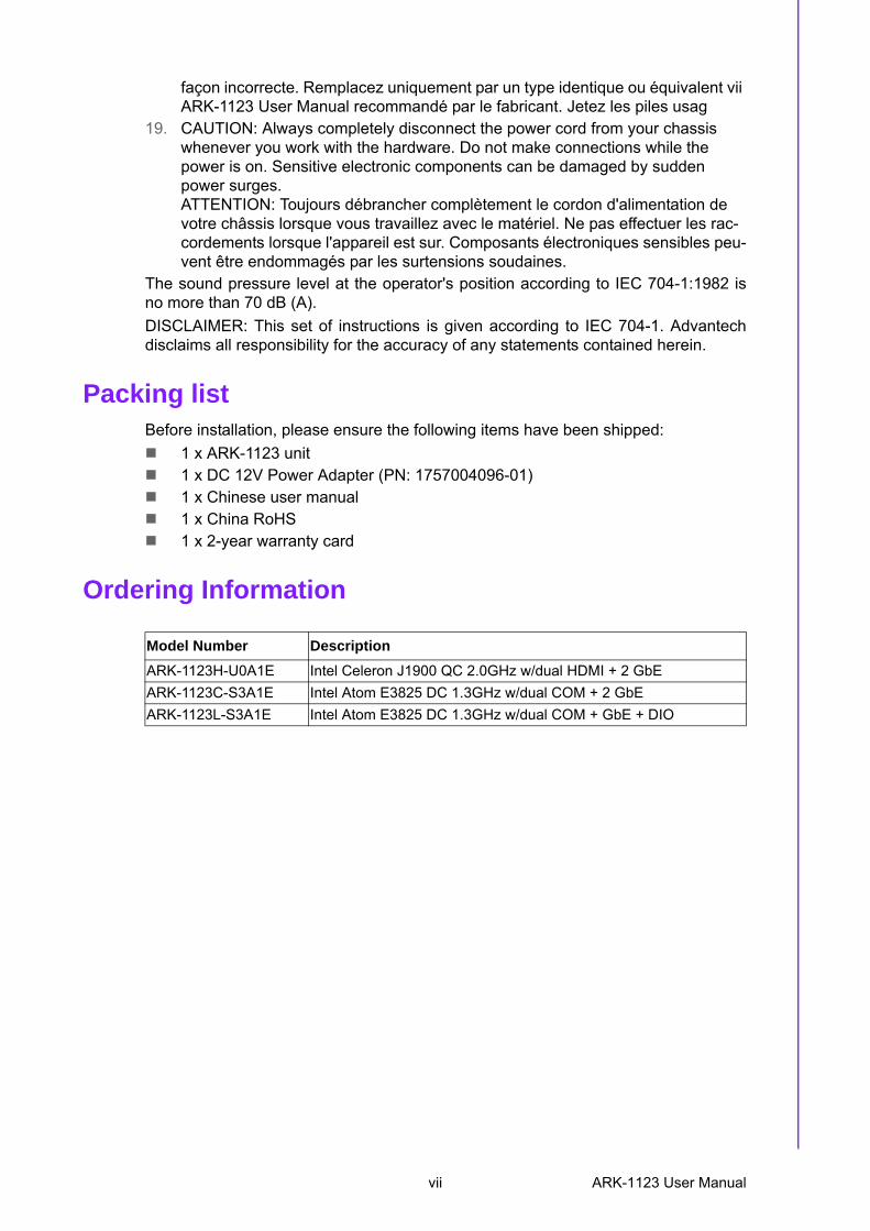
Packing listBefore installation, please ensure the following items have been shipped:
1 x ARK-1123 unit 1 x DC 12V Power Adapter (PN: 1757004096-01) 1 x Chinese user manual 1 x China RoHS 1 x 2-year warranty card
Ordering Information
Model Number Description
ARK-1123H-U0A1E Intel Celeron J1900 QC 2.0GHz w/dual HDMI + 2 GbE
ARK-1123C-S3A1E Intel Atom E3825 DC 1.3GHz w/dual COM + 2 GbE
ARK-1123L-S3A1E Intel Atom E3825 DC 1.3GHz w/dual COM + GbE + DIO
vii ARK-1123 User Manual
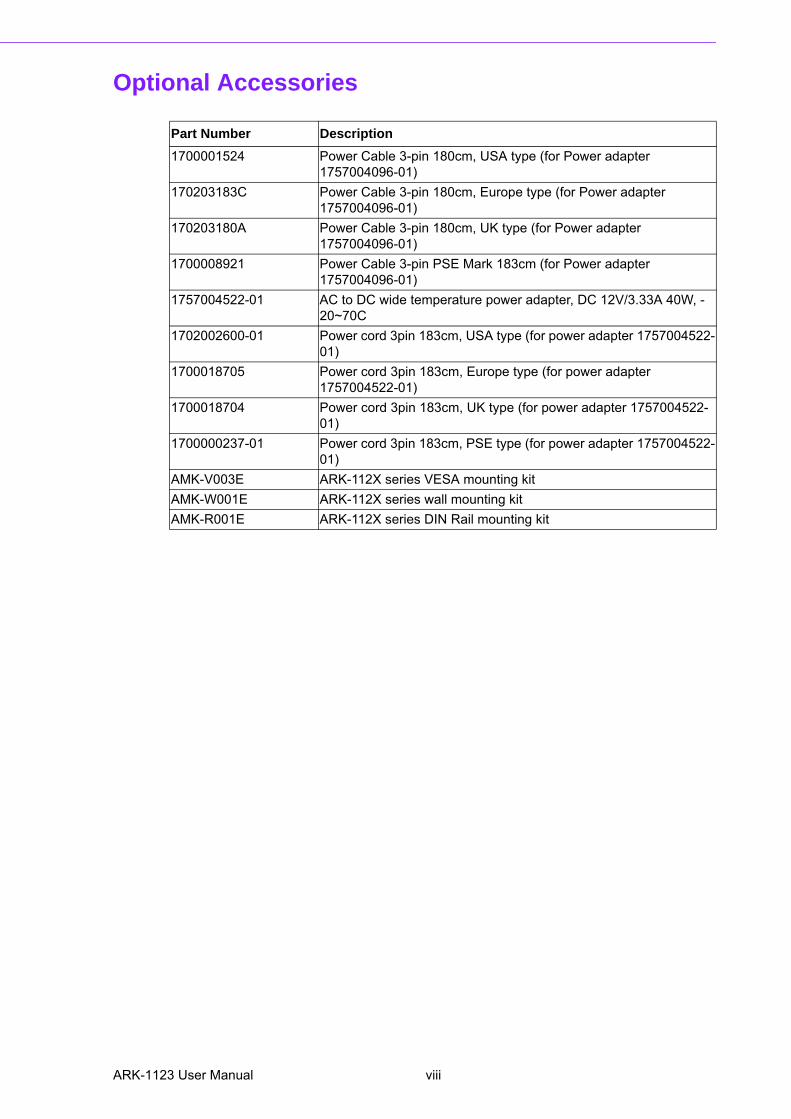
Optional Accessories
Part Number Description
1700001524 Power Cable 3-pin 180cm, USA type (for Power adapter 1757004096-01)
170203183C Power Cable 3-pin 180cm, Europe type (for Power adapter 1757004096-01)
170203180A Power Cable 3-pin 180cm, UK type (for Power adapter 1757004096-01)
1700008921 Power Cable 3-pin PSE Mark 183cm (for Power adapter 1757004096-01)
1757004522-01 AC to DC wide temperature power adapter, DC 12V/3.33A 40W, -20~70C
1702002600-01 Power cord 3pin 183cm, USA type (for power adapter 1757004522-01)
1700018705 Power cord 3pin 183cm, Europe type (for power adapter 1757004522-01)
1700018704 Power cord 3pin 183cm, UK type (for power adapter 1757004522-01)
1700000237-01 Power cord 3pin 183cm, PSE type (for power adapter 1757004522-01)
AMK-V003E ARK-112X series VESA mounting kit
AMK-W001E ARK-112X series wall mounting kit
AMK-R001E ARK-112X series DIN Rail mounting kit
ARK-1123 User Manual viii
Contents
Chapter 1 General Introduction ...........................11.1 Introduction ............................................................................................... 21.2 Features .................................................................................................... 21.3 Specifications ............................................................................................ 2
1.3.1 General ......................................................................................... 21.3.2 Display .......................................................................................... 31.3.3 Ethernet ........................................................................................ 31.3.4 Power Consumption...................................................................... 31.3.5 Power Requirement ...................................................................... 3
1.4 Environmental Specifications .................................................................... 31.5 Mechanical Specifications......................................................................... 4
1.5.1 ARK-1123H Dimensions ............................................................... 4Figure 1.1 ARK-1123H mechanical dimension drawing .............. 4
1.5.2 ARK-1123C Dimensions ............................................................... 5Figure 1.2 ARK-1123C mechanical dimension drawing .............. 5
1.5.3 ARK-1123L Dimensions................................................................ 5Figure 1.3 ARK-1123L mechanical dimension drawing............... 5
Chapter 2 Hardware Installation ..........................72.1 Jumpers .................................................................................................... 8
2.1.1 Jumper Description ....................................................................... 82.1.2 Jumper list..................................................................................... 8
Table 2.1: Jumper List ................................................................. 82.1.3 Jumper Settings ............................................................................ 8
Table 2.2: J1: LCD Power/Auto Power on................................... 82.2 ARK-1123 I/O Indication ........................................................................... 9
Figure 2.1 ARK-1123H front view ................................................ 9Figure 2.2 ARK-1123H rear view................................................. 9Figure 2.3 ARK-1123C front view .............................................. 10Figure 2.4 ARK-1123C rear view............................................... 10Figure 2.5 ARK-1123C front view .............................................. 10Figure 2.6 ARK-1123C rear view............................................... 11
2.3 ARK-1123H External I/O Connectors...................................................... 112.3.1 Power ON/OFF Button................................................................ 11
Figure 2.7 Power ON/OFF Button ............................................. 112.3.2 Power Input Connector ............................................................... 11
Figure 2.8 Power Input Connector............................................. 112.3.3 Ethernet Connector (LAN) .......................................................... 12
Figure 2.9 Ethernet Connector .................................................. 12Table 2.3: Ethernet Connector Pin Assignments....................... 12
2.3.4 USB Connectors ......................................................................... 13Figure 2.10USB Connector......................................................... 13Table 2.4: USB Connector Pin Assignments............................. 13
2.3.5 Audio Connector ......................................................................... 13Figure 2.11Audio Connector....................................................... 13Table 2.5: DIO Connector Pin Assignments.............................. 13
2.3.6 COM Connector .......................................................................... 14Figure 2.12COM Port Connector ................................................ 14Table 2.6: COM Connector Pin Assignments............................ 14
2.3.7 HDMI Connector ......................................................................... 14Figure 2.13HDMI Connector....................................................... 14Table 2.7: HDMI / Display Port Connector Pin Assignments..... 15
2.3.8 HDD LED Indicator ..................................................................... 15
ix ARK-1123 User Manual
2.4 ARK-1123C External I/O Connectors ..................................................... 152.4.1 Power ON/OFF Button................................................................ 15
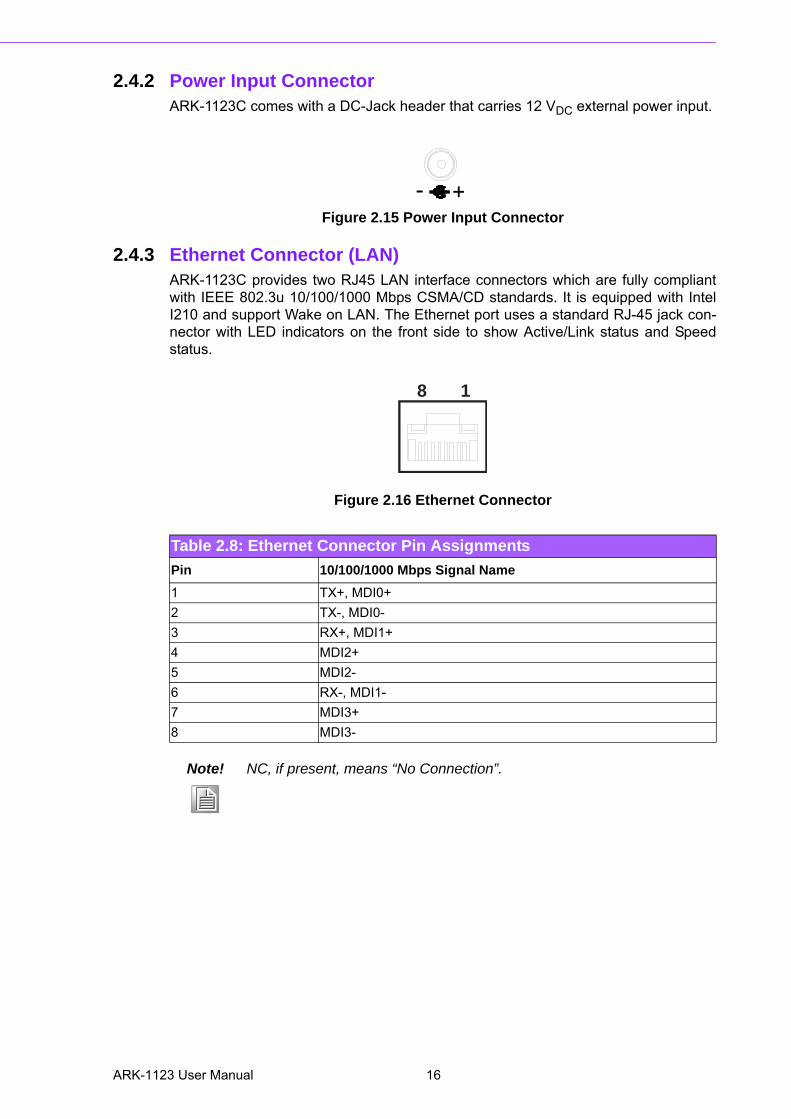
Figure 2.14Power ON/OFF Button ............................................. 152.4.2 Power Input Connector ............................................................... 16
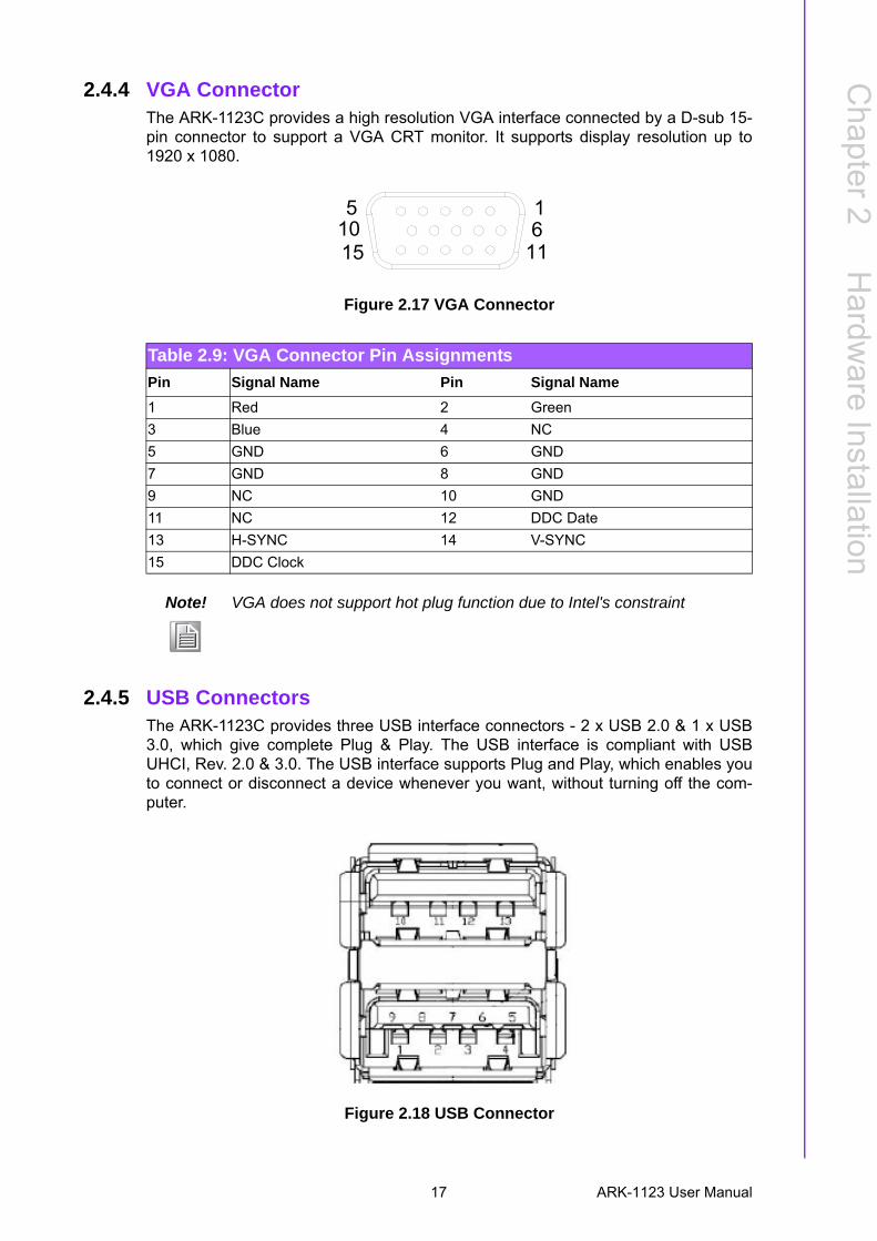
Figure 2.15Power Input Connector............................................. 162.4.3 Ethernet Connector (LAN) .......................................................... 16
Figure 2.16Ethernet Connector .................................................. 16Table 2.8: Ethernet Connector Pin Assignments ...................... 16
2.4.4 VGA Connector........................................................................... 17Figure 2.17VGA Connector ........................................................ 17Table 2.9: VGA Connector Pin Assignments ............................ 17
2.4.5 USB Connectors ......................................................................... 17Figure 2.18USB Connector ........................................................ 17Table 2.10:USB Connector Pin Assignments............................. 18
2.4.6 Audio Connector ......................................................................... 18Figure 2.19Audio Connector....................................................... 18Table 2.11:Audio Connector Pin Assignments........................... 18
2.4.7 COM Connector.......................................................................... 18Figure 2.20COM Port Connector................................................ 18Table 2.12:COM Connector Pin Assignments............................ 18
2.4.8 HDD LED Indicator ..................................................................... 192.5 ARK-1123L External I/O Connectors ...................................................... 19
2.5.1 Power ON/OFF Button................................................................ 19Figure 2.21Power ON/OFF Button ............................................. 19
2.5.2 Power Input Connector ............................................................... 19Figure 2.22Power Input Connector............................................. 19
2.5.3 Ethernet Connector (LAN) .......................................................... 20Figure 2.23Ethernet Connector .................................................. 20Table 2.13:Ethernet Connector Pin Assignments ...................... 20
2.5.4 VGA Connector........................................................................... 20Figure 2.24VGA Connector ........................................................ 20Table 2.14:VGA Connector Pin Assignments ............................ 20
2.5.5 USB Connectors ......................................................................... 21Figure 2.25USB Connector ........................................................ 21Table 2.15:USB Connector Pin Assignments............................. 21
2.5.6 Audio Connector ......................................................................... 22Figure 2.26Audio Connector....................................................... 22Table 2.16:Audio Connector Pin Assignments........................... 22
2.5.7 COM Connector.......................................................................... 22Figure 2.27COM Port Connector................................................ 22Table 2.17:COM Connector Pin Assignments............................ 22
2.5.8 DIO Connector............................................................................ 23Table 2.18:DIO Connector Pin Assignments.............................. 23
2.5.9 HDD LED Indicator ..................................................................... 232.6 Peripheral Installation ............................................................................. 24
2.6.1 HDD Installation.......................................................................... 242.6.2 mSATA HD Installation ............................................................... 262.6.3 RAM Installation.......................................................................... 27
Chapter 3 BIOS Settings .................................... 293.1 BIOS Setup ............................................................................................. 303.2 Entering Setup ........................................................................................ 31
3.2.1 Main Setup.................................................................................. 313.2.2 Advanced BIOS Features Setup................................................. 323.2.3 Chipset Configuration ................................................................. 453.2.4 Security....................................................................................... 543.2.5 Boot ............................................................................................ 553.2.6 Save & Exit ................................................................................. 56
ARK-1123 User Manual x

Appendix A WDT & GPIO Sample Code ...............57A.1 Watchdog Timer Sample Code ............................................................... 58
xi ARK-1123 User Manual

ARK-1123 User Manual xii
Chapter 1
1 General IntroductionThis chapter gives background information on ARK-1123.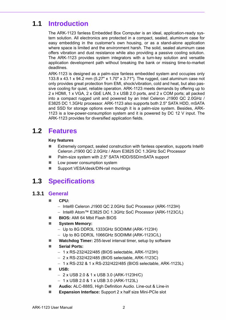
1.1 IntroductionThe ARK-1123 fanless Embedded Box Computer is an ideal, application-ready sys-tem solution. All electronics are protected in a compact, sealed, aluminum case foreasy embedding in the customer's own housing, or as a stand-alone applicationwhere space is limited and the environment harsh. The solid, sealed aluminum caseoffers vibration and dust resistance while also providing a passive cooling solution.The ARK-1123 provides system integrators with a turn-key solution and versatileapplication development path without breaking the bank or missing time-to-marketdeadlines.
ARK-1123 is designed as a palm-size fanless embedded system and occupies only133.8 x 43.1 x 94.2 mm (5.27" x 1.70" x 3.71"). The rugged, cast aluminum case notonly provides great protection from EMI, shock/vibration, cold and heat, but also pas-sive cooling for quiet, reliable operation. ARK-1123 meets demands by offering up to2 x HDMI, 1 x VGA, 2 x GbE LAN, 3 x USB 2.0 ports, and 2 x COM ports; all packedinto a compact rugged unit and powered by an Intel Celeron J1900 QC 2.0GHz /E3825 DC 1.3GHz processor. ARK-1123 also supports both 2.5" SATA HDD, mSATAand SSD for storage options even though it is a palm-size system. Besides, ARK-1123 is a low-power-consumption system and it is powered by DC 12 V input. TheARK-1123 provides for diversified application fields.
1.2 FeaturesKey features
Extremely compact, sealed construction with fanless operation, supports Intel® Celeron J1900 QC 2.0GHz / Atom E3825 DC 1.3GHz SoC Processor
Palm-size system with 2.5" SATA HDD/SSD/mSATA support Low power consumption system Support VESA/desk/DIN-rail mountings
1.3 Specifications
1.3.1 General CPU:
– Intel® Celeron J1900 QC 2.0GHz SoC Processor (ARK-1123H)– Intel® Atom™ E3825 DC 1.3GHz SoC Processor (ARK-1123C/L)
BIOS: AMI 64 Mbit Flash BIOS System Memory:
– Up to 8G DDR3L 1333GHz SODIMM (ARK-1123H)– Up to 8G DDR3L 1066GHz SODIMM (ARK-1123C/L)
Watchdog Timer: 255-level interval timer, setup by software Serial Ports:
– 1 x RS-232/422/485 (BIOS selectable, ARK-1123H)– 2 x RS-232/422/485 (BIOS selectable, ARK-1123C)– 1 x RS-232 & 1 x RS-232/422/485 (BIOS selectable, ARK-1123L)
USB: – 2 x USB 2.0 & 1 x USB 3.0 (ARK-1123H/C)– 1 x USB 2.0 & 1 x USB 3.0 (ARK-1123L)
Audio: ALC-888S, High Definition Audio. Line-out & Line-in Expansion Interface: Support 2 x half size Mini-PCIe slot
ARK-1123 User Manual 2
Chapter 1
GeneralIntroduction
– 1 x Full-size Mini PCIe, support WLAN or WWAN module– 1 x Half-size Mini PCIe, support Half-size mSATA module
Storage:– Supports SSD or 1 x 2.5" SATAIlI HDD 7 mm height only for ARK-1123C/L– Supports H/S mSATA storage device (Suggest to assembly by CTOS or T-
Part due to complex installation for ARK-1123H & C)– DIO: 1 x DIO (ARK-1123L)
1.3.2 Display Chipset: Intel® Atom SoC integrated Graphic Engine:
– DirectX* 11.1, OGL 3.0, OCL 1.1, OGL ES 2.0– Encode: H264, MPEG2/4, VC1, WMV9– Decode: H264, MPEG2
VGA: Supports up to 1920 x 1200 at 60 Hz (ARK-1123C/L)** VGA does not support hot plug function due to Intel's constraint
HDMI: Supports up to 1920 x 1080 at 60 Hz (ARK-1123H)** HDMI does not support hot plug function due to Intel's constraint** No audio function on HDMI 2 due to Intel's constraint
1.3.3 Ethernet Chipset: Intel I210 Speed: 10/100/1000 Mbps, support Wake on LAN Interface: Up to 2 x RJ45 (ARK-1123H/C) Standard: Compliant with IEEE 802.3, IEEE 802.3u, IEEE 802.3x, IEEE 8023y,
IEEE 802.ab.
1.3.4 Power Consumption Input Voltage: DC 12V Power Adapter: AC to DC, DC12 V/3 A, 36 W with lockable design
1.3.5 Power Requirement Power Input: Single DC 12V RTC battery: 3 V/210 mAh
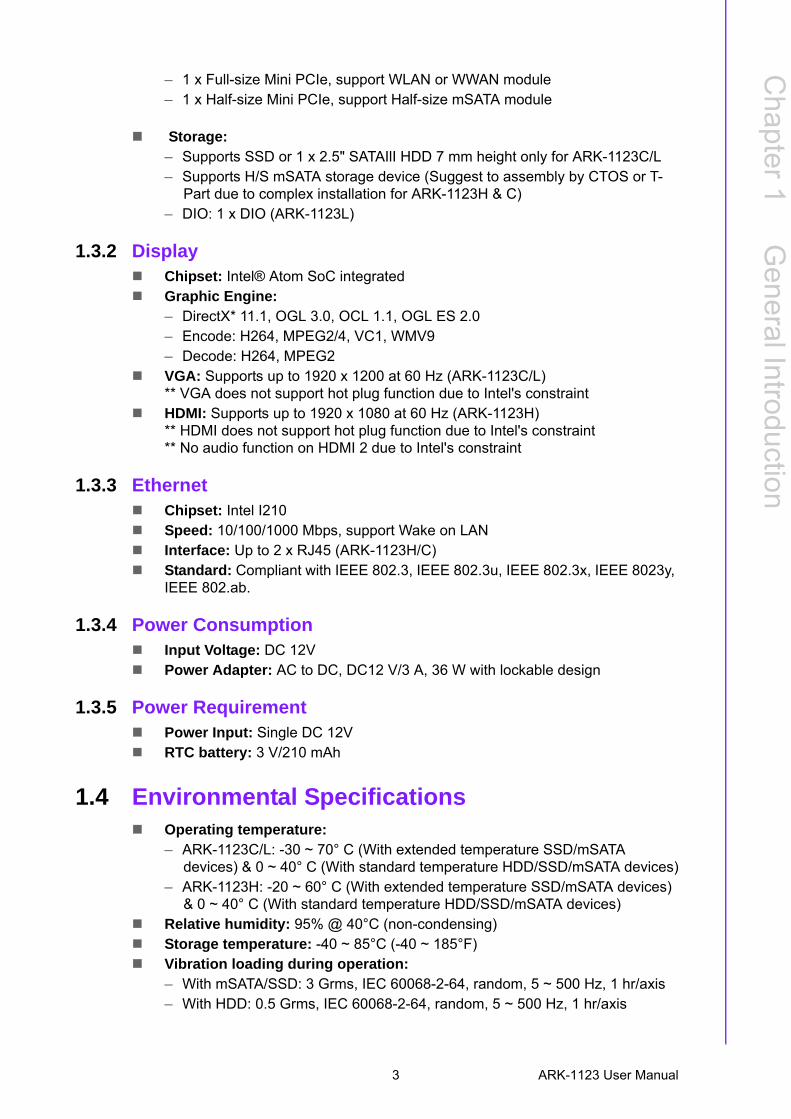
1.4 Environmental Specifications Operating temperature:
– ARK-1123C/L: -30 ~ 70° C (With extended temperature SSD/mSATA devices) & 0 ~ 40° C (With standard temperature HDD/SSD/mSATA devices)
– ARK-1123H: -20 ~ 60° C (With extended temperature SSD/mSATA devices) & 0 ~ 40° C (With standard temperature HDD/SSD/mSATA devices)
Relative humidity: 95% @ 40°C (non-condensing) Storage temperature: -40 ~ 85°C (-40 ~ 185°F) Vibration loading during operation:
– With mSATA/SSD: 3 Grms, IEC 60068-2-64, random, 5 ~ 500 Hz, 1 hr/axis– With HDD: 0.5 Grms, IEC 60068-2-64, random, 5 ~ 500 Hz, 1 hr/axis
3 ARK-1123 User Manual
Shock during operation: – With mSATA/SSD: 30 G, IEC 60068-2-27, half sine, 11 ms duration– With HDD: 10 G, IEC 60068-2-27, half sine, 11 ms duration
Safety: UL,CB,CCC,BSMI EMC: CE, FCC Class A, BSMI, CCC
1.5 Mechanical Specifications
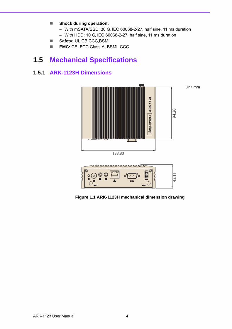
1.5.1 ARK-1123H Dimensions
Figure 1.1 ARK-1123H mechanical dimension drawing
Unit:mm
ARK-1123 User Manual 4
Chapter 1
GeneralIntroduction
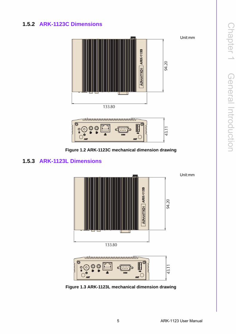
1.5.2 ARK-1123C Dimensions
Figure 1.2 ARK-1123C mechanical dimension drawing
1.5.3 ARK-1123L Dimensions
Figure 1.3 ARK-1123L mechanical dimension drawing
Unit:mm
Unit:mm
5 ARK-1123 User Manual

ARK-1123 User Manual 6
Chapter 2
2 Hardware InstallationThis chapter introduces external IO and the installation of ARK-1123 Hardware.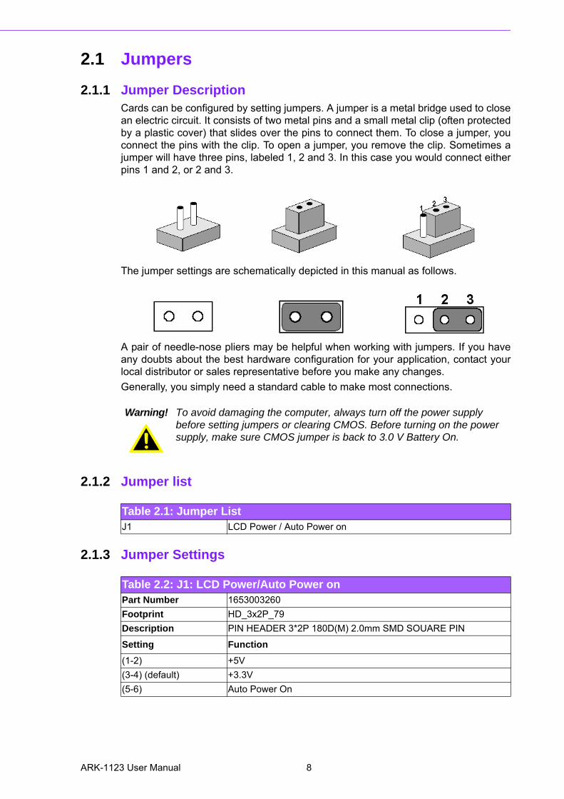
2.1 Jumpers
2.1.1 Jumper DescriptionCards can be configured by setting jumpers. A jumper is a metal bridge used to closean electric circuit. It consists of two metal pins and a small metal clip (often protectedby a plastic cover) that slides over the pins to connect them. To close a jumper, youconnect the pins with the clip. To open a jumper, you remove the clip. Sometimes ajumper will have three pins, labeled 1, 2 and 3. In this case you would connect eitherpins 1 and 2, or 2 and 3.
The jumper settings are schematically depicted in this manual as follows.
A pair of needle-nose pliers may be helpful when working with jumpers. If you haveany doubts about the best hardware configuration for your application, contact yourlocal distributor or sales representative before you make any changes.
Generally, you simply need a standard cable to make most connections.
2.1.2 Jumper list
2.1.3 Jumper Settings
Warning! To avoid damaging the computer, always turn off the power supply before setting jumpers or clearing CMOS. Before turning on the power supply, make sure CMOS jumper is back to 3.0 V Battery On.
Table 2.1: Jumper ListJ1 LCD Power / Auto Power on
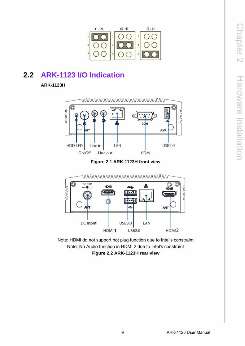
Table 2.2: J1: LCD Power/Auto Power onPart Number 1653003260
Footprint HD_3x2P_79
Description PIN HEADER 3*2P 180D(M) 2.0mm SMD SOUARE PIN
Setting Function
(1-2) +5V
(3-4) (default) +3.3V
(5-6) Auto Power On
ARK-1123 User Manual 8
Chapter 2
Hardw
areInstallation
2.2 ARK-1123 I/O IndicationARK-1123H
Figure 2.1 ARK-1123H front view
Note: HDMI do not support hot plug function due to Intel's constraint
Note: No Audio function in HDMI 2 due to Intel's constraint
Figure 2.2 ARK-1123H rear view
9 ARK-1123 User Manual
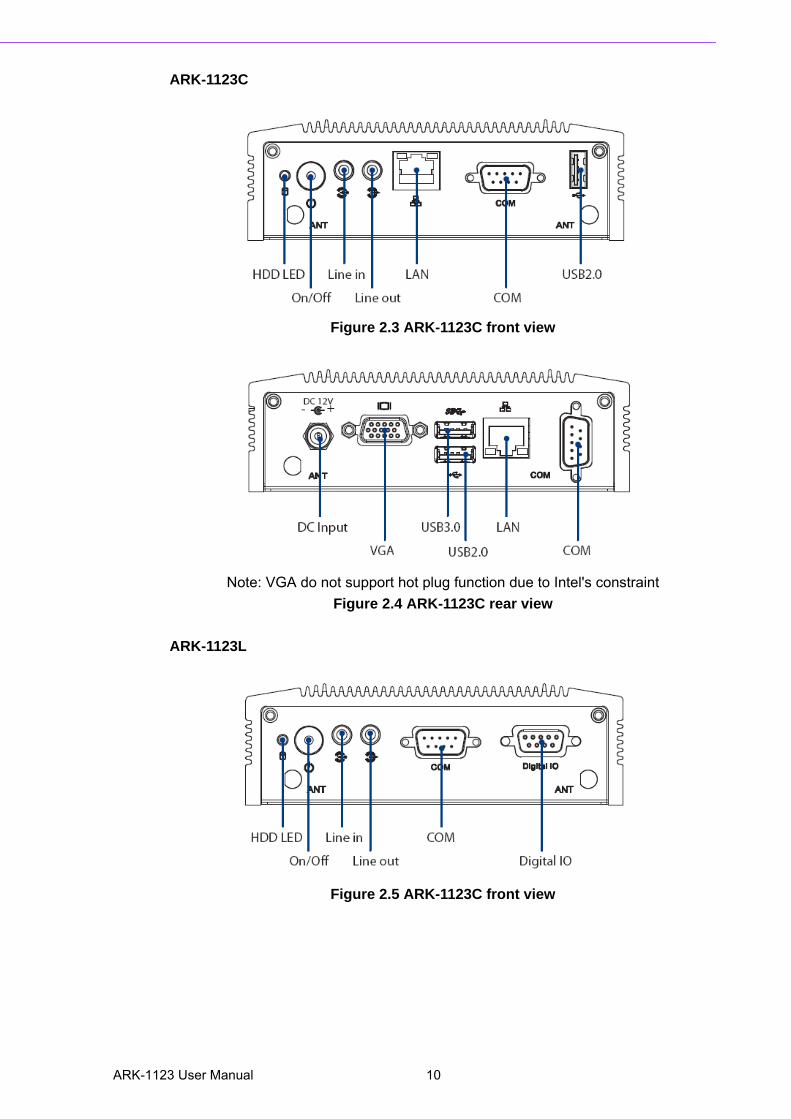
ARK-1123C
Figure 2.3 ARK-1123C front view
Note: VGA do not support hot plug function due to Intel's constraint
Figure 2.4 ARK-1123C rear view
ARK-1123L
Figure 2.5 ARK-1123C front view
ARK-1123 User Manual 10
Chapter 2
Hardw
areInstallation
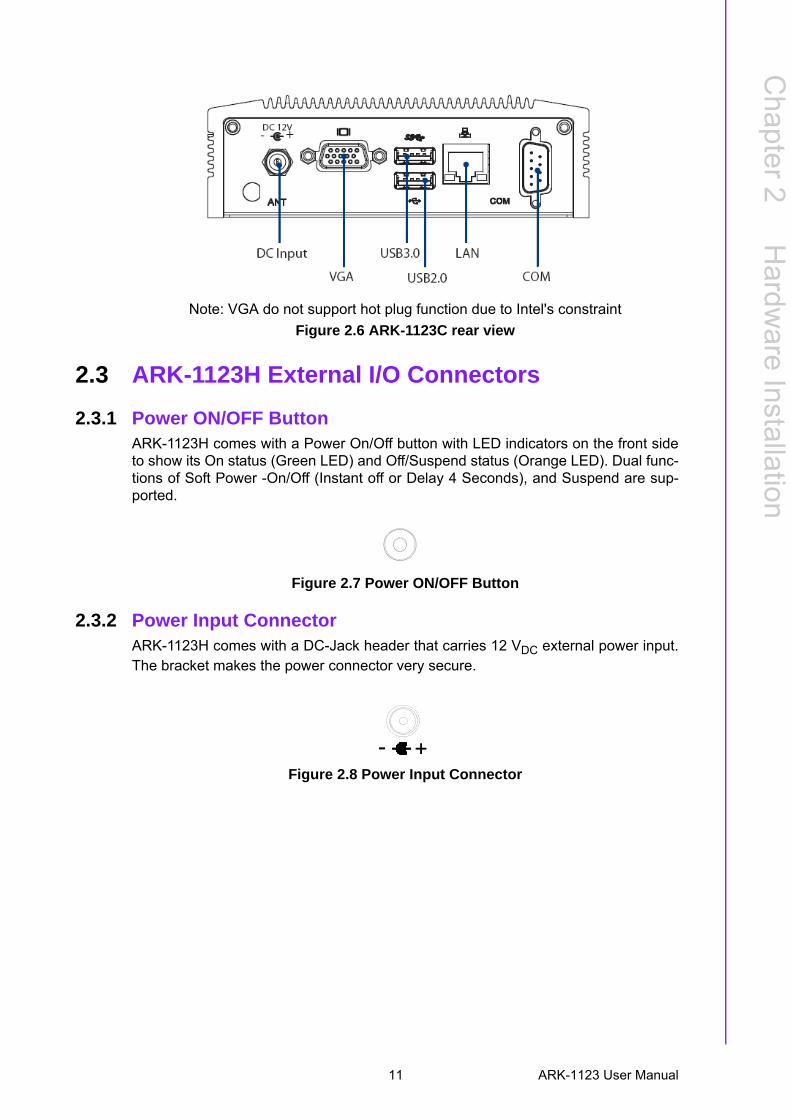
Note: VGA do not support hot plug function due to Intel's constraint
Figure 2.6 ARK-1123C rear view
2.3 ARK-1123H External I/O Connectors
2.3.1 Power ON/OFF ButtonARK-1123H comes with a Power On/Off button with LED indicators on the front sideto show its On status (Green LED) and Off/Suspend status (Orange LED). Dual func-tions of Soft Power -On/Off (Instant off or Delay 4 Seconds), and Suspend are sup-ported.
Figure 2.7 Power ON/OFF Button
2.3.2 Power Input ConnectorARK-1123H comes with a DC-Jack header that carries 12 VDC external power input.The bracket makes the power connector very secure.
Figure 2.8 Power Input Connector
11 ARK-1123 User Manual
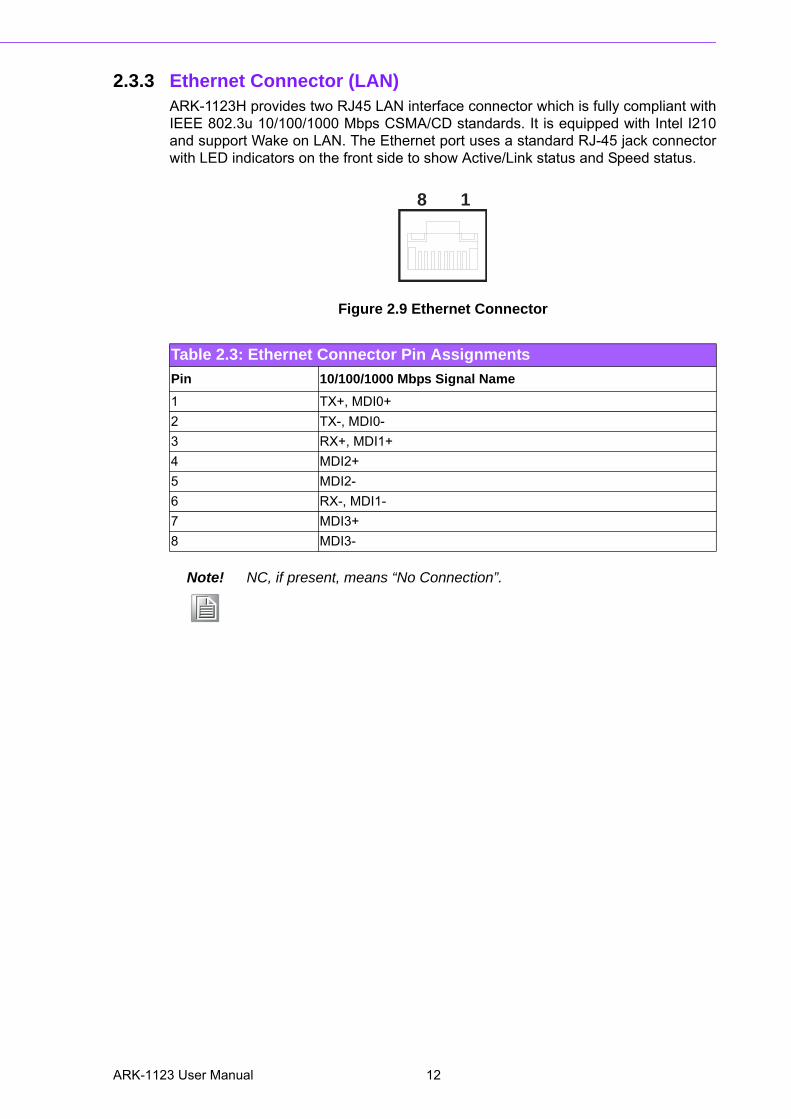
2.3.3 Ethernet Connector (LAN)ARK-1123H provides two RJ45 LAN interface connector which is fully compliant withIEEE 802.3u 10/100/1000 Mbps CSMA/CD standards. It is equipped with Intel I210and support Wake on LAN. The Ethernet port uses a standard RJ-45 jack connectorwith LED indicators on the front side to show Active/Link status and Speed status.
Figure 2.9 Ethernet Connector
Table 2.3: Ethernet Connector Pin Assignments
Pin 10/100/1000 Mbps Signal Name
1 TX+, MDI0+
2 TX-, MDI0-
3 RX+, MDI1+
4 MDI2+
5 MDI2-
6 RX-, MDI1-
7 MDI3+
8 MDI3-
Note! NC, if present, means “No Connection”.
18
ARK-1123 User Manual 12
Chapter 2
Hardw
areInstallation
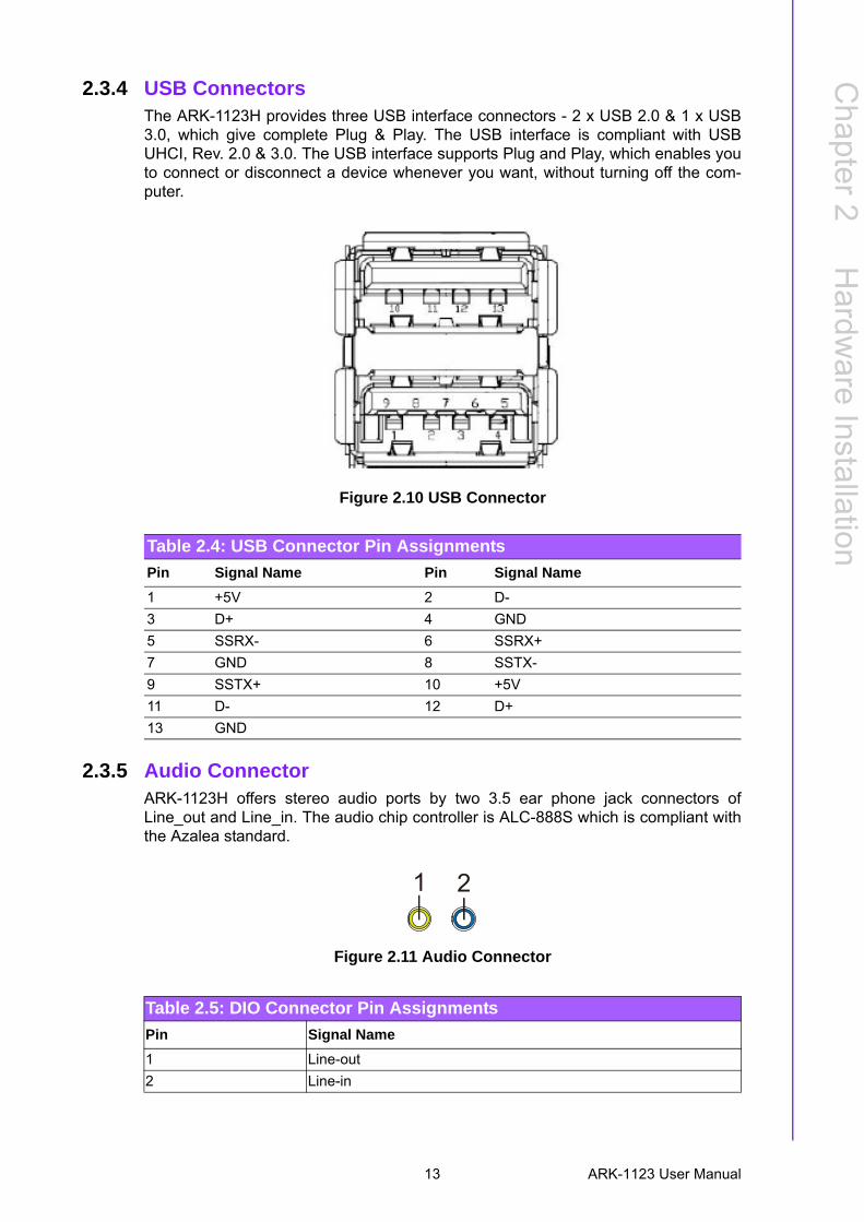
2.3.4 USB ConnectorsThe ARK-1123H provides three USB interface connectors - 2 x USB 2.0 & 1 x USB3.0, which give complete Plug & Play. The USB interface is compliant with USBUHCI, Rev. 2.0 & 3.0. The USB interface supports Plug and Play, which enables youto connect or disconnect a device whenever you want, without turning off the com-puter.
Figure 2.10 USB Connector
2.3.5 Audio Connector ARK-1123H offers stereo audio ports by two 3.5 ear phone jack connectors ofLine_out and Line_in. The audio chip controller is ALC-888S which is compliant withthe Azalea standard.
Figure 2.11 Audio Connector
Table 2.4: USB Connector Pin Assignments
Pin Signal Name Pin Signal Name
1 +5V 2 D-
3 D+ 4 GND
5 SSRX- 6 SSRX+
7 GND 8 SSTX-
9 SSTX+ 10 +5V
11 D- 12 D+
13 GND
Table 2.5: DIO Connector Pin Assignments
Pin Signal Name
1 Line-out
2 Line-in
21
13 ARK-1123 User Manual
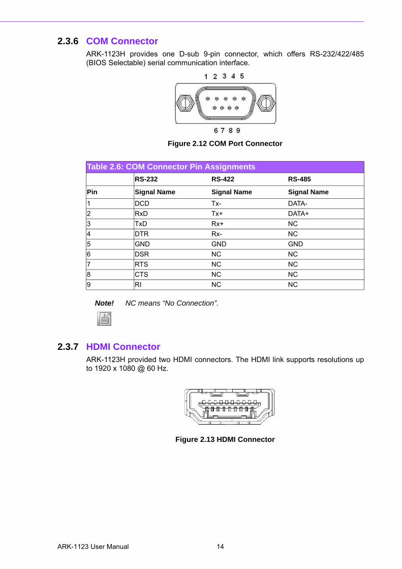
2.3.6 COM ConnectorARK-1123H provides one D-sub 9-pin connector, which offers RS-232/422/485(BIOS Selectable) serial communication interface.
Figure 2.12 COM Port Connector
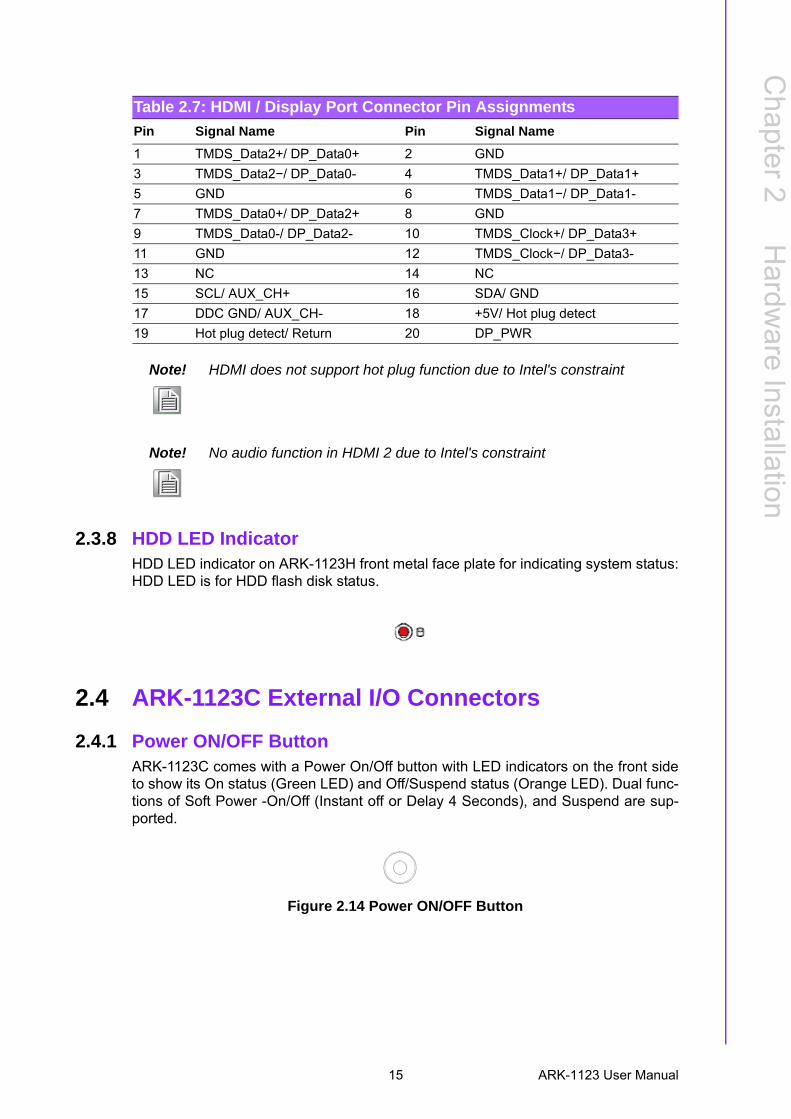
2.3.7 HDMI ConnectorARK-1123H provided two HDMI connectors. The HDMI link supports resolutions upto 1920 x 1080 @ 60 Hz.
Figure 2.13 HDMI Connector
Table 2.6: COM Connector Pin Assignments
RS-232 RS-422 RS-485
Pin Signal Name Signal Name Signal Name
1 DCD Tx- DATA-
2 RxD Tx+ DATA+
3 TxD Rx+ NC
4 DTR Rx- NC
5 GND GND GND
6 DSR NC NC
7 RTS NC NC
8 CTS NC NC
9 RI NC NC
Note! NC means “No Connection”.
ARK-1123 User Manual 14
Chapter 2
Hardw
areInstallation
2.3.8 HDD LED IndicatorHDD LED indicator on ARK-1123H front metal face plate for indicating system status:HDD LED is for HDD flash disk status.
2.4 ARK-1123C External I/O Connectors
2.4.1 Power ON/OFF ButtonARK-1123C comes with a Power On/Off button with LED indicators on the front sideto show its On status (Green LED) and Off/Suspend status (Orange LED). Dual func-tions of Soft Power -On/Off (Instant off or Delay 4 Seconds), and Suspend are sup-ported.
Figure 2.14 Power ON/OFF Button
Table 2.7: HDMI / Display Port Connector Pin Assignments
Pin Signal Name Pin Signal Name
1 TMDS_Data2+/ DP_Data0+ 2 GND
3 TMDS_Data2−/ DP_Data0- 4 TMDS_Data1+/ DP_Data1+
5 GND 6 TMDS_Data1−/ DP_Data1-
7 TMDS_Data0+/ DP_Data2+ 8 GND
9 TMDS_Data0-/ DP_Data2- 10 TMDS_Clock+/ DP_Data3+
11 GND 12 TMDS_Clock−/ DP_Data3-
13 NC 14 NC
15 SCL/ AUX_CH+ 16 SDA/ GND
17 DDC GND/ AUX_CH- 18 +5V/ Hot plug detect
19 Hot plug detect/ Return 20 DP_PWR
Note! HDMI does not support hot plug function due to Intel's constraint
Note! No audio function in HDMI 2 due to Intel's constraint
15 ARK-1123 User Manual
2.4.2 Power Input ConnectorARK-1123C comes with a DC-Jack header that carries 12 VDC external power input.
Figure 2.15 Power Input Connector
2.4.3 Ethernet Connector (LAN)ARK-1123C provides two RJ45 LAN interface connectors which are fully compliantwith IEEE 802.3u 10/100/1000 Mbps CSMA/CD standards. It is equipped with IntelI210 and support Wake on LAN. The Ethernet port uses a standard RJ-45 jack con-nector with LED indicators on the front side to show Active/Link status and Speedstatus.
Figure 2.16 Ethernet Connector
Table 2.8: Ethernet Connector Pin Assignments
Pin 10/100/1000 Mbps Signal Name
1 TX+, MDI0+
2 TX-, MDI0-
3 RX+, MDI1+
4 MDI2+
5 MDI2-
6 RX-, MDI1-
7 MDI3+
8 MDI3-
Note! NC, if present, means “No Connection”.
18
ARK-1123 User Manual 16
Chapter 2
Hardw
areInstallation
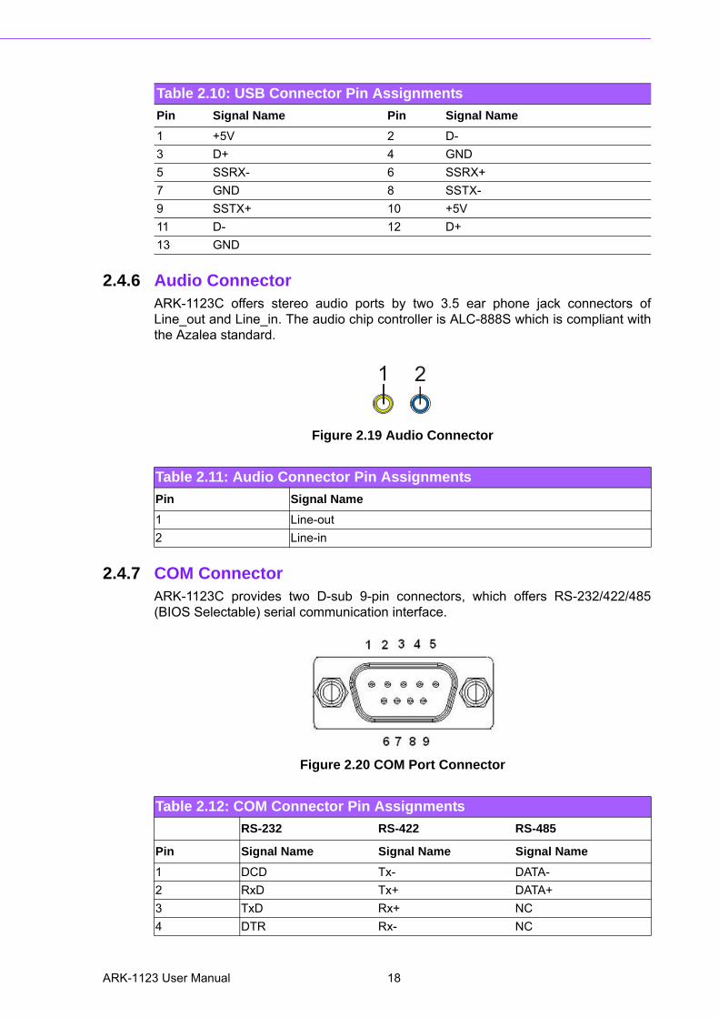
2.4.4 VGA ConnectorThe ARK-1123C provides a high resolution VGA interface connected by a D-sub 15-pin connector to support a VGA CRT monitor. It supports display resolution up to1920 x 1080.
Figure 2.17 VGA Connector
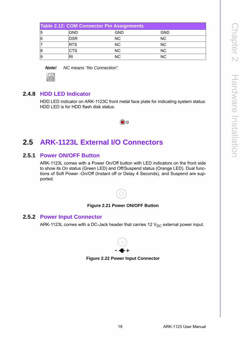
2.4.5 USB ConnectorsThe ARK-1123C provides three USB interface connectors - 2 x USB 2.0 & 1 x USB3.0, which give complete Plug & Play. The USB interface is compliant with USBUHCI, Rev. 2.0 & 3.0. The USB interface supports Plug and Play, which enables youto connect or disconnect a device whenever you want, without turning off the com-puter.
Figure 2.18 USB Connector
Table 2.9: VGA Connector Pin Assignments
Pin Signal Name Pin Signal Name
1 Red 2 Green
3 Blue 4 NC
5 GND 6 GND
7 GND 8 GND
9 NC 10 GND
11 NC 12 DDC Date
13 H-SYNC 14 V-SYNC
15 DDC Clock
Note! VGA does not support hot plug function due to Intel's constraint
156
111015
17 ARK-1123 User Manual
2.4.6 Audio Connector ARK-1123C offers stereo audio ports by two 3.5 ear phone jack connectors ofLine_out and Line_in. The audio chip controller is ALC-888S which is compliant withthe Azalea standard.
Figure 2.19 Audio Connector
2.4.7 COM ConnectorARK-1123C provides two D-sub 9-pin connectors, which offers RS-232/422/485(BIOS Selectable) serial communication interface.
Figure 2.20 COM Port Connector
Table 2.10: USB Connector Pin Assignments
Pin Signal Name Pin Signal Name
1 +5V 2 D-
3 D+ 4 GND
5 SSRX- 6 SSRX+
7 GND 8 SSTX-
9 SSTX+ 10 +5V
11 D- 12 D+
13 GND
Table 2.11: Audio Connector Pin Assignments
Pin Signal Name
1 Line-out
2 Line-in
21
Table 2.12: COM Connector Pin Assignments
RS-232 RS-422 RS-485
Pin Signal Name Signal Name Signal Name
1 DCD Tx- DATA-
2 RxD Tx+ DATA+
3 TxD Rx+ NC
4 DTR Rx- NC
ARK-1123 User Manual 18
Chapter 2
Hardw
areInstallation
2.4.8 HDD LED IndicatorHDD LED indicator on ARK-1123C front metal face plate for indicating system status:HDD LED is for HDD flash disk status.
2.5 ARK-1123L External I/O Connectors
2.5.1 Power ON/OFF ButtonARK-1123L comes with a Power On/Off button with LED indicators on the front sideto show its On status (Green LED) and Off/Suspend status (Orange LED). Dual func-tions of Soft Power -On/Off (Instant off or Delay 4 Seconds), and Suspend are sup-ported.
Figure 2.21 Power ON/OFF Button
2.5.2 Power Input ConnectorARK-1123L comes with a DC-Jack header that carries 12 VDC external power input.
Figure 2.22 Power Input Connector
5 GND GND GND
6 DSR NC NC
7 RTS NC NC
8 CTS NC NC
9 RI NC NC
Note! NC means “No Connection”.
Table 2.12: COM Connector Pin Assignments
19 ARK-1123 User Manual
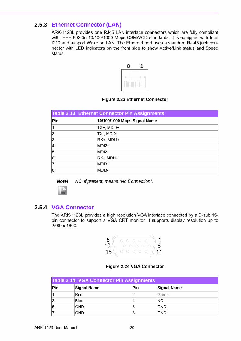
2.5.3 Ethernet Connector (LAN)ARK-1123L provides one RJ45 LAN interface connectors which are fully compliantwith IEEE 802.3u 10/100/1000 Mbps CSMA/CD standards. It is equipped with IntelI210 and support Wake on LAN. The Ethernet port uses a standard RJ-45 jack con-nector with LED indicators on the front side to show Active/Link status and Speedstatus.
Figure 2.23 Ethernet Connector
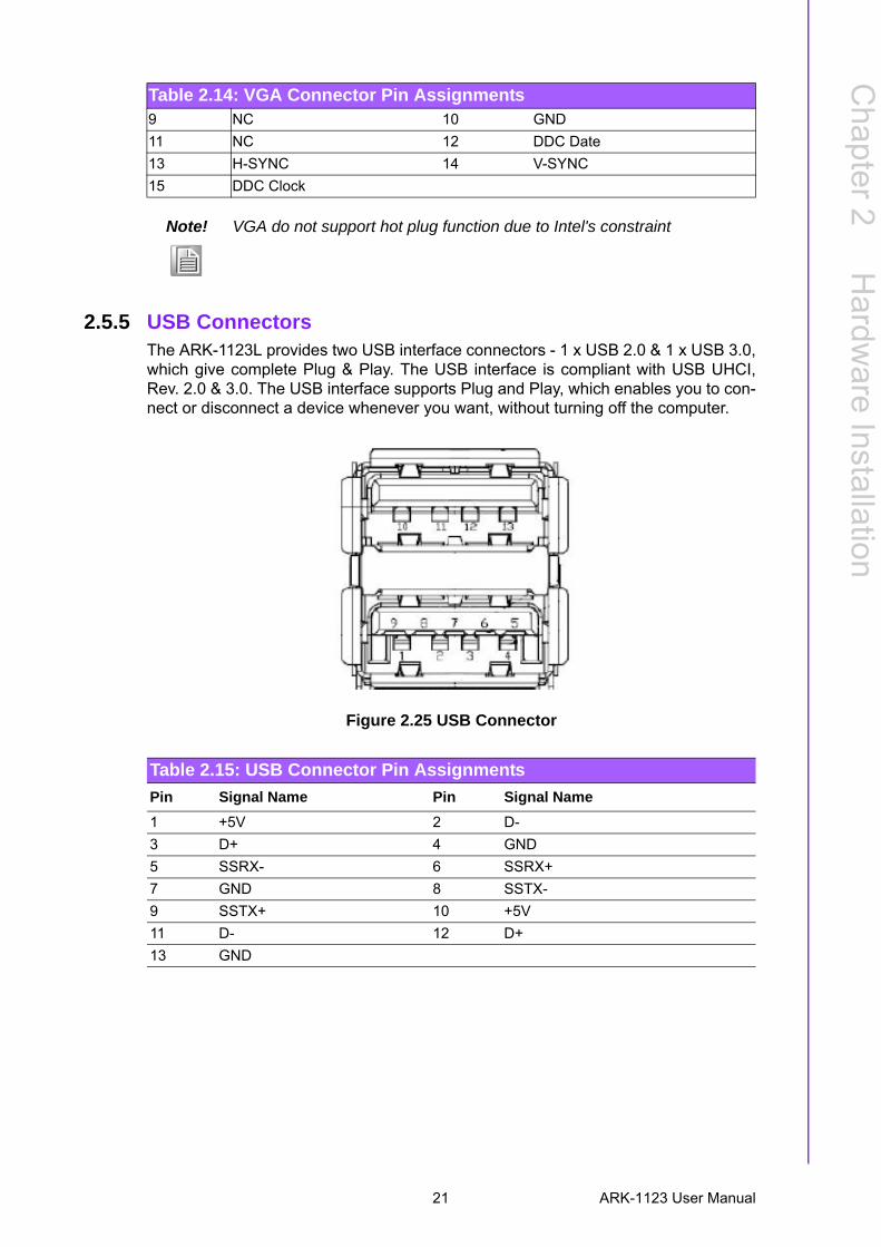
2.5.4 VGA ConnectorThe ARK-1123L provides a high resolution VGA interface connected by a D-sub 15-pin connector to support a VGA CRT monitor. It supports display resolution up to2560 x 1600.
Figure 2.24 VGA Connector
Table 2.13: Ethernet Connector Pin Assignments
Pin 10/100/1000 Mbps Signal Name
1 TX+, MDI0+
2 TX-, MDI0-
3 RX+, MDI1+
4 MDI2+
5 MDI2-
6 RX-, MDI1-
7 MDI3+
8 MDI3-
Note! NC, if present, means “No Connection”.
18
Table 2.14: VGA Connector Pin Assignments
Pin Signal Name Pin Signal Name
1 Red 2 Green
3 Blue 4 NC
5 GND 6 GND
7 GND 8 GND
156
111015
ARK-1123 User Manual 20
Chapter 2
Hardw
areInstallation
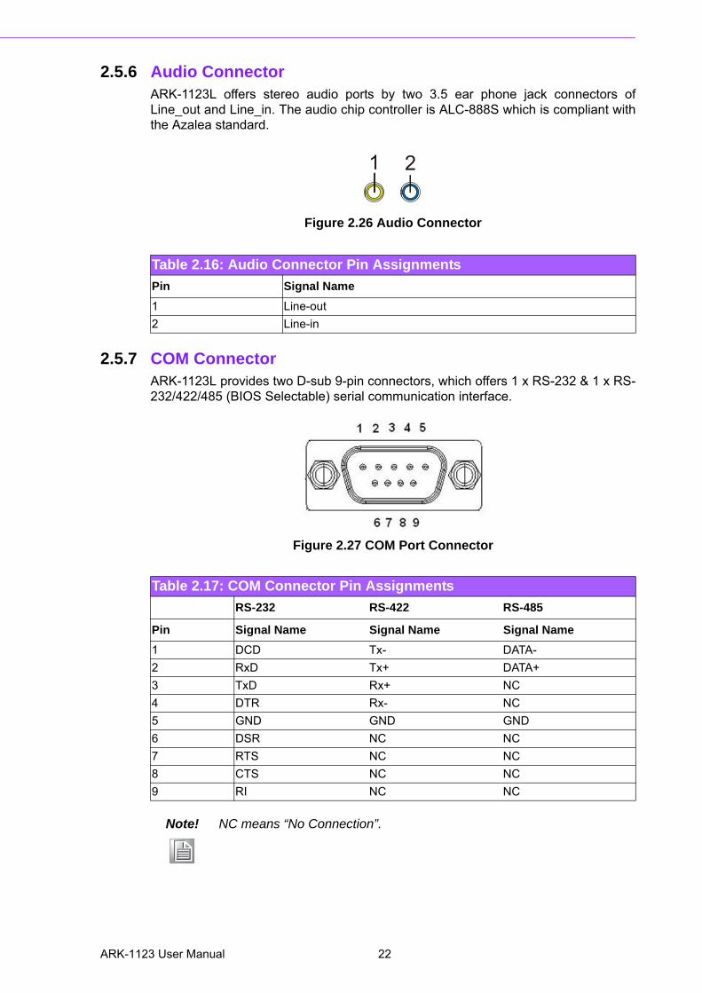
2.5.5 USB ConnectorsThe ARK-1123L provides two USB interface connectors - 1 x USB 2.0 & 1 x USB 3.0,which give complete Plug & Play. The USB interface is compliant with USB UHCI,Rev. 2.0 & 3.0. The USB interface supports Plug and Play, which enables you to con-nect or disconnect a device whenever you want, without turning off the computer.
Figure 2.25 USB Connector
9 NC 10 GND
11 NC 12 DDC Date
13 H-SYNC 14 V-SYNC
15 DDC Clock
Note! VGA do not support hot plug function due to Intel's constraint
Table 2.14: VGA Connector Pin Assignments
Table 2.15: USB Connector Pin Assignments
Pin Signal Name Pin Signal Name
1 +5V 2 D-
3 D+ 4 GND
5 SSRX- 6 SSRX+
7 GND 8 SSTX-
9 SSTX+ 10 +5V
11 D- 12 D+
13 GND
21 ARK-1123 User Manual
2.5.6 Audio Connector ARK-1123L offers stereo audio ports by two 3.5 ear phone jack connectors ofLine_out and Line_in. The audio chip controller is ALC-888S which is compliant withthe Azalea standard.
Figure 2.26 Audio Connector
2.5.7 COM ConnectorARK-1123L provides two D-sub 9-pin connectors, which offers 1 x RS-232 & 1 x RS-232/422/485 (BIOS Selectable) serial communication interface.
Figure 2.27 COM Port Connector
Table 2.16: Audio Connector Pin Assignments
Pin Signal Name
1 Line-out
2 Line-in
21
Table 2.17: COM Connector Pin Assignments
RS-232 RS-422 RS-485
Pin Signal Name Signal Name Signal Name
1 DCD Tx- DATA-
2 RxD Tx+ DATA+
3 TxD Rx+ NC
4 DTR Rx- NC
5 GND GND GND
6 DSR NC NC
7 RTS NC NC
8 CTS NC NC
9 RI NC NC
Note! NC means “No Connection”.
ARK-1123 User Manual 22
Chapter 2
Hardw
areInstallation
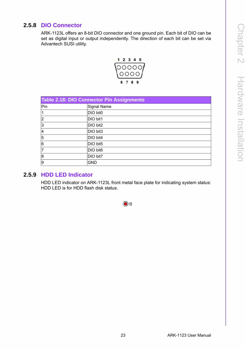
2.5.8 DIO ConnectorARK-1123L offers an 8-bit DIO connector and one ground pin. Each bit of DIO can beset as digital input or output independently. The direction of each bit can be set viaAdvantech SUSI utility.
2.5.9 HDD LED IndicatorHDD LED indicator on ARK-1123L front metal face plate for indicating system status:HDD LED is for HDD flash disk status.
Table 2.18: DIO Connector Pin AssignmentsPin Signal Name
1 DIO bit0
2 DIO bit1
3 DIO bit2
4 DIO bit3
5 DIO bit4
6 DIO bit5
7 DIO bit6
8 DIO bit7
9 GND
23 ARK-1123 User Manual
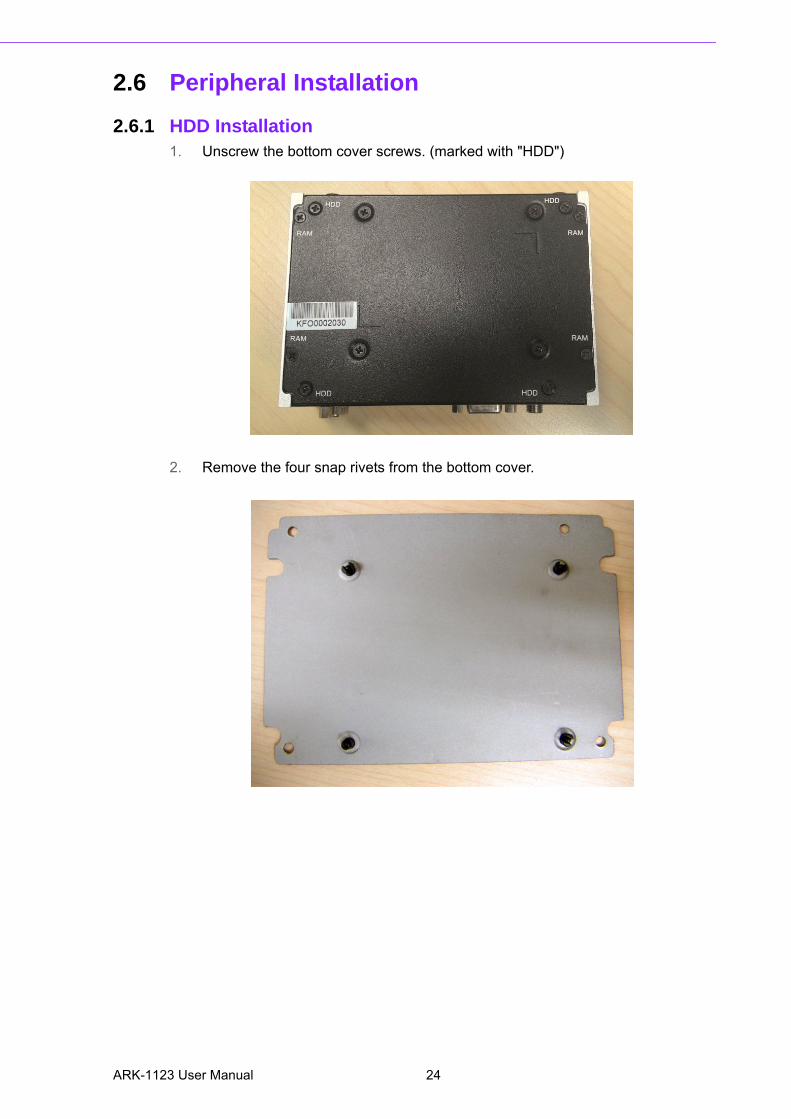
2.6 Peripheral Installation
2.6.1 HDD Installation1. Unscrew the bottom cover screws. (marked with "HDD")
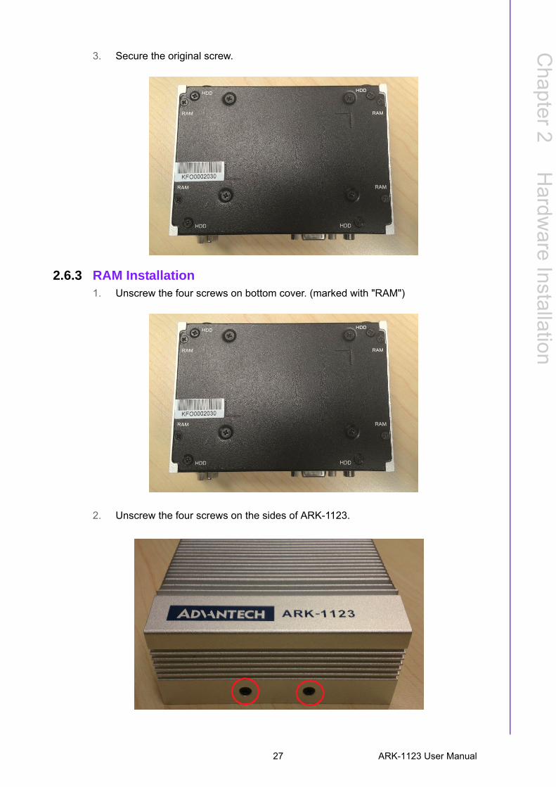
2. Remove the four snap rivets from the bottom cover.
ARK-1123 User Manual 24

Chapter 2
Hardw
areInstallation
3. Secure 2.5" SATA HDD onto the bottom cover. The screws are in the accessory box.
4. Connect SATA signal and power cable to the 2.5" SATA HDD.
5. Secure the bottom cover in its original position.
25 ARK-1123 User Manual

2.6.2 mSATA HD Installation** Below installation is for ARK-1123L only. For ARK-1123H & ARK-1123C, wesuggest to install by CTOS due to complex installation with H/S mSATA.
1. Unscrew the bottom cover screws (Marked “HDD”).
2. Insert mSTAT storage into the slot and secure the screw to fix the mSATA stor-age.
ARK-1123 User Manual 26
Chapter 2
Hardw
areInstallation
3. Secure the original screw.
2.6.3 RAM Installation1. Unscrew the four screws on bottom cover. (marked with "RAM")
2. Unscrew the four screws on the sides of ARK-1123.
27 ARK-1123 User Manual
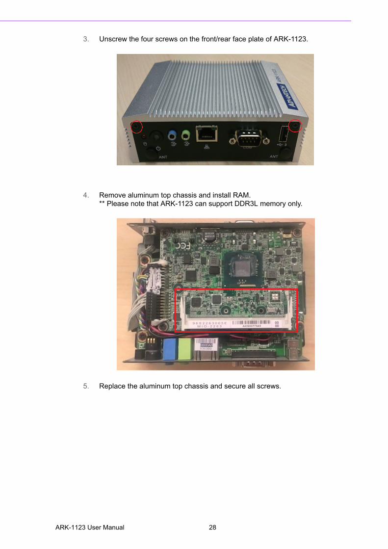
3. Unscrew the four screws on the front/rear face plate of ARK-1123.
4. Remove aluminum top chassis and install RAM.** Please note that ARK-1123 can support DDR3L memory only.
5. Replace the aluminum top chassis and secure all screws.
ARK-1123 User Manual 28
Chapter 3
3 BIOS Settings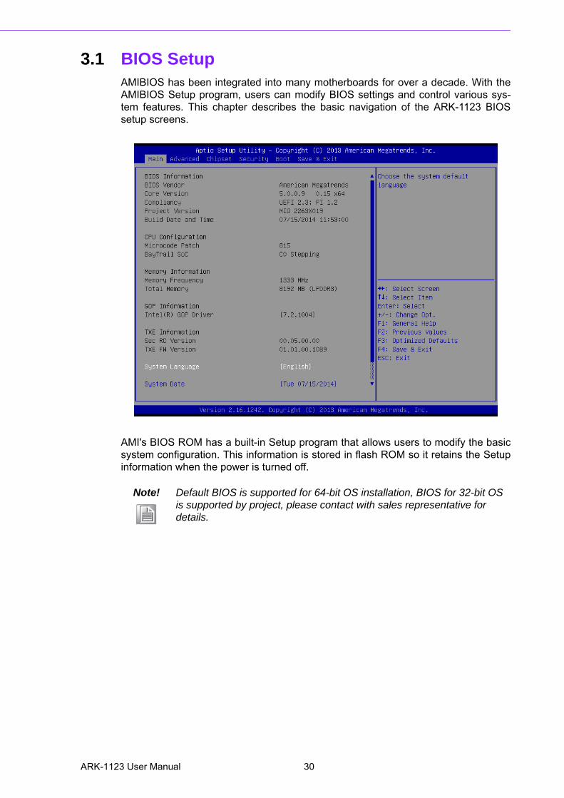
3.1 BIOS SetupAMIBIOS has been integrated into many motherboards for over a decade. With theAMIBIOS Setup program, users can modify BIOS settings and control various sys-tem features. This chapter describes the basic navigation of the ARK-1123 BIOSsetup screens.
AMI's BIOS ROM has a built-in Setup program that allows users to modify the basicsystem configuration. This information is stored in flash ROM so it retains the Setupinformation when the power is turned off.
Note! Default BIOS is supported for 64-bit OS installation, BIOS for 32-bit OS is supported by project, please contact with sales representative for details.
ARK-1123 User Manual 30
Chapter 3
BIO
S S
ettings
3.2 Entering SetupTurn on the computer and check for the -patch" code. If there is a number assignedto the patch code, it means that the BIOS supports your CPU. If there is no numberassigned to the patch code, please contact an Advantech application engineer toobtain an up-to-date patch code file. This will ensure that your CPU's system status isvalid. After ensuring that you have a number assigned to the patch code, press<DEL> and you will immediately be allowed to enter Setup.
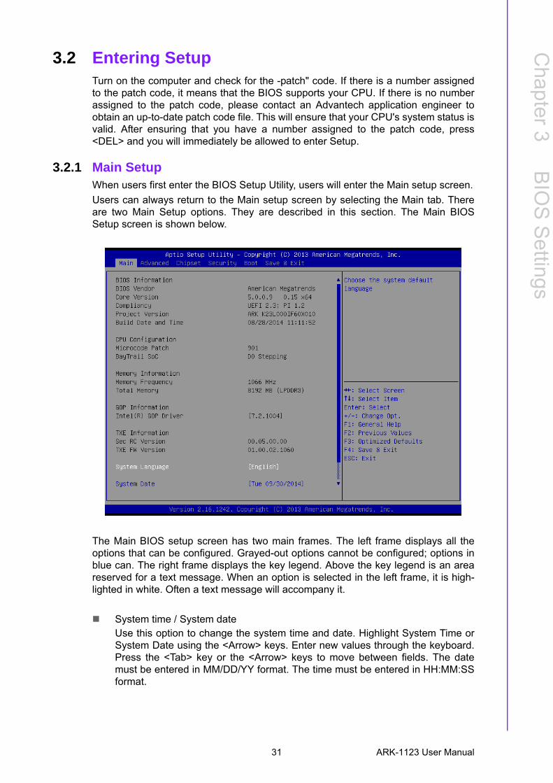
3.2.1 Main SetupWhen users first enter the BIOS Setup Utility, users will enter the Main setup screen.
Users can always return to the Main setup screen by selecting the Main tab. Thereare two Main Setup options. They are described in this section. The Main BIOSSetup screen is shown below.
The Main BIOS setup screen has two main frames. The left frame displays all theoptions that can be configured. Grayed-out options cannot be configured; options inblue can. The right frame displays the key legend. Above the key legend is an areareserved for a text message. When an option is selected in the left frame, it is high-lighted in white. Often a text message will accompany it.
System time / System dateUse this option to change the system time and date. Highlight System Time orSystem Date using the <Arrow> keys. Enter new values through the keyboard.Press the <Tab> key or the <Arrow> keys to move between fields. The datemust be entered in MM/DD/YY format. The time must be entered in HH:MM:SSformat.
31 ARK-1123 User Manual
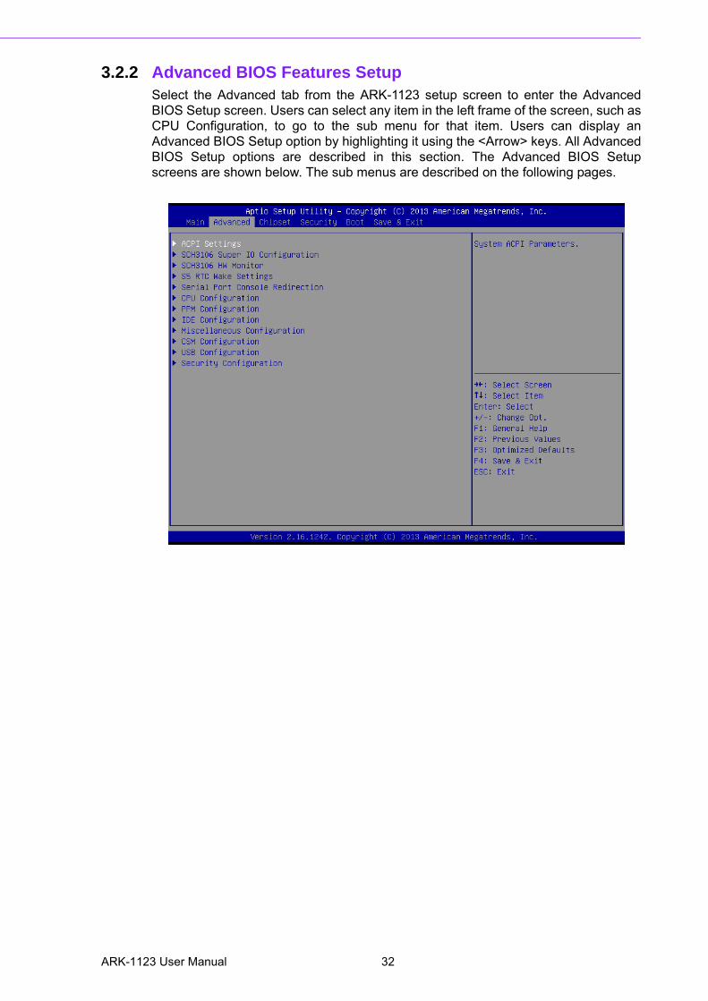
3.2.2 Advanced BIOS Features SetupSelect the Advanced tab from the ARK-1123 setup screen to enter the AdvancedBIOS Setup screen. Users can select any item in the left frame of the screen, such asCPU Configuration, to go to the sub menu for that item. Users can display anAdvanced BIOS Setup option by highlighting it using the <Arrow> keys. All AdvancedBIOS Setup options are described in this section. The Advanced BIOS Setupscreens are shown below. The sub menus are described on the following pages.
ARK-1123 User Manual 32
Chapter 3
BIO
S S
ettings
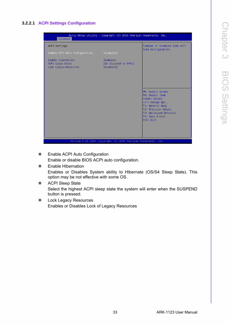
3.2.2.1 ACPI Settings Configuration
Enable ACPI Auto ConfigurationEnable or disable BIOS ACPI auto configuration.
Enable HibernationEnables or Disables System ability to Hibernate (OS/S4 Sleep State). Thisoption may be not effective with some OS.
ACPI Sleep StateSelect the highest ACPI sleep state the system will enter when the SUSPENDbutton is pressed.
Lock Legacy ResourcesEnables or Disables Lock of Legacy Resources
33 ARK-1123 User Manual
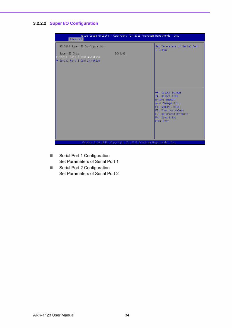
3.2.2.2 Super I/O Configuration
Serial Port 1 Configuration Set Parameters of Serial Port 1
Serial Port 2 Configuration Set Parameters of Serial Port 2
ARK-1123 User Manual 34
Chapter 3
BIO
S S
ettings
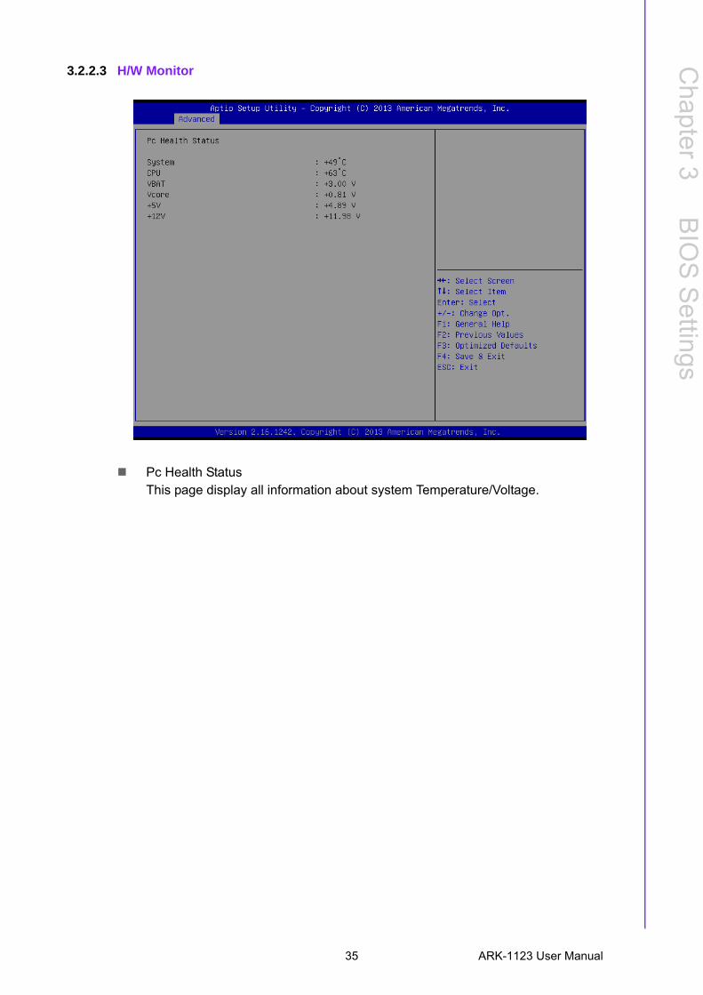
3.2.2.3 H/W Monitor
Pc Health StatusThis page display all information about system Temperature/Voltage.
35 ARK-1123 User Manual
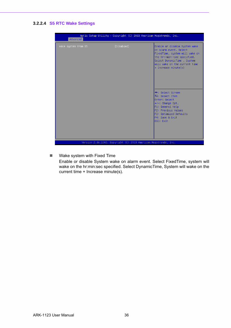
3.2.2.4 S5 RTC Wake Settings
Wake system with Fixed TimeEnable or disable System wake on alarm event. Select FixedTime, system willwake on the hr:min:sec specified. Select DynamicTime, System will wake on thecurrent time + Increase minute(s).
ARK-1123 User Manual 36
Chapter 3
BIO
S S
ettings
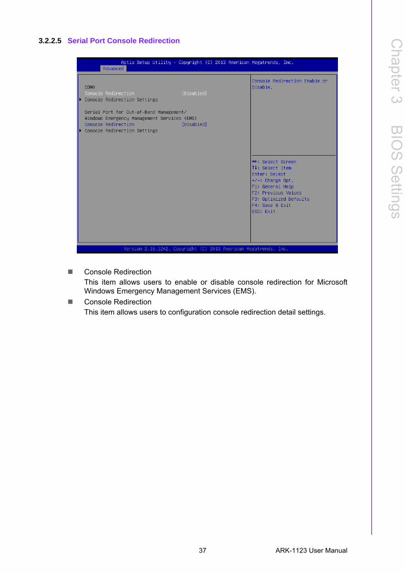
3.2.2.5 Serial Port Console Redirection
Console RedirectionThis item allows users to enable or disable console redirection for MicrosoftWindows Emergency Management Services (EMS).
Console RedirectionThis item allows users to configuration console redirection detail settings.
37 ARK-1123 User Manual
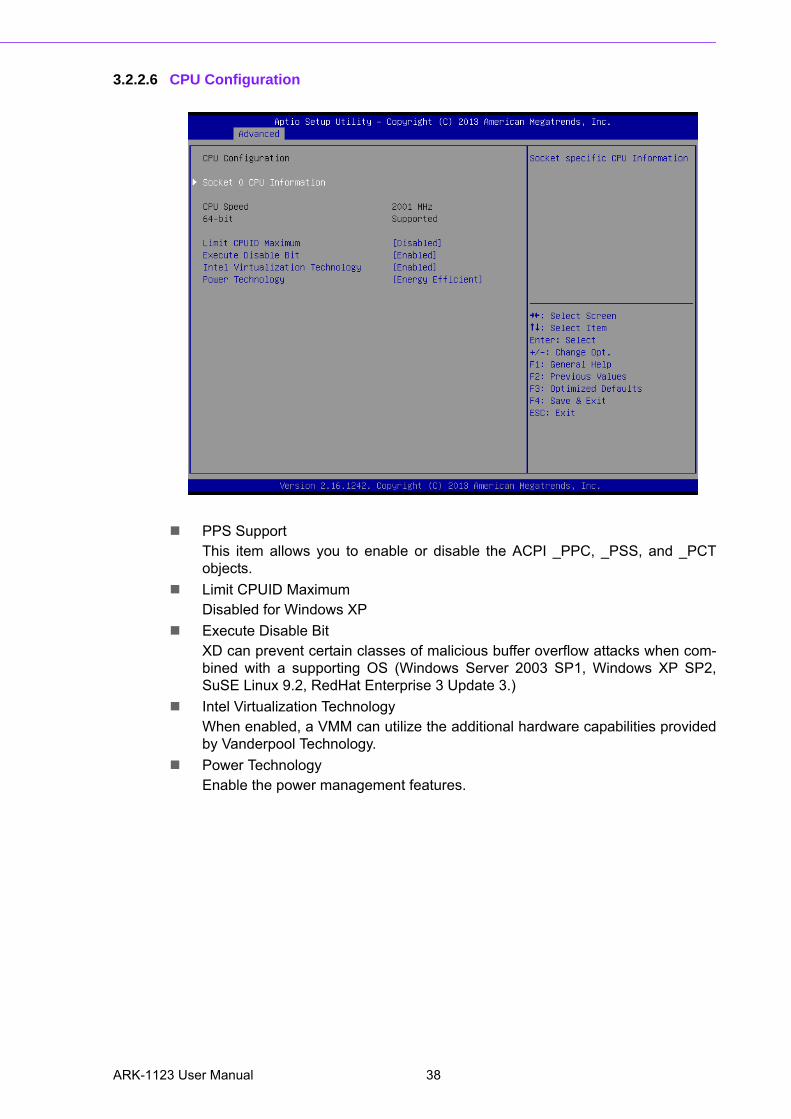
3.2.2.6 CPU Configuration
PPS SupportThis item allows you to enable or disable the ACPI _PPC, _PSS, and _PCTobjects.
Limit CPUID MaximumDisabled for Windows XP
Execute Disable BitXD can prevent certain classes of malicious buffer overflow attacks when com-bined with a supporting OS (Windows Server 2003 SP1, Windows XP SP2,SuSE Linux 9.2, RedHat Enterprise 3 Update 3.)
Intel Virtualization TechnologyWhen enabled, a VMM can utilize the additional hardware capabilities providedby Vanderpool Technology.
Power TechnologyEnable the power management features.
ARK-1123 User Manual 38
Chapter 3
BIO
S S
ettings
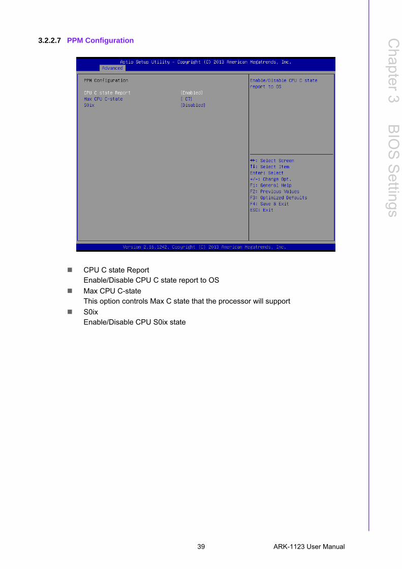
3.2.2.7 PPM Configuration
CPU C state ReportEnable/Disable CPU C state report to OS
Max CPU C-stateThis option controls Max C state that the processor will support
S0ixEnable/Disable CPU S0ix state
39 ARK-1123 User Manual
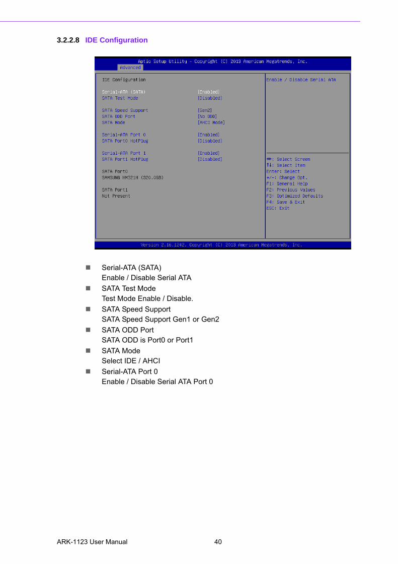
3.2.2.8 IDE Configuration
Serial-ATA (SATA)Enable / Disable Serial ATA
SATA Test ModeTest Mode Enable / Disable.
SATA Speed SupportSATA Speed Support Gen1 or Gen2
SATA ODD PortSATA ODD is Port0 or Port1
SATA ModeSelect IDE / AHCI
Serial-ATA Port 0Enable / Disable Serial ATA Port 0
ARK-1123 User Manual 40
Chapter 3
BIO
S S
ettings
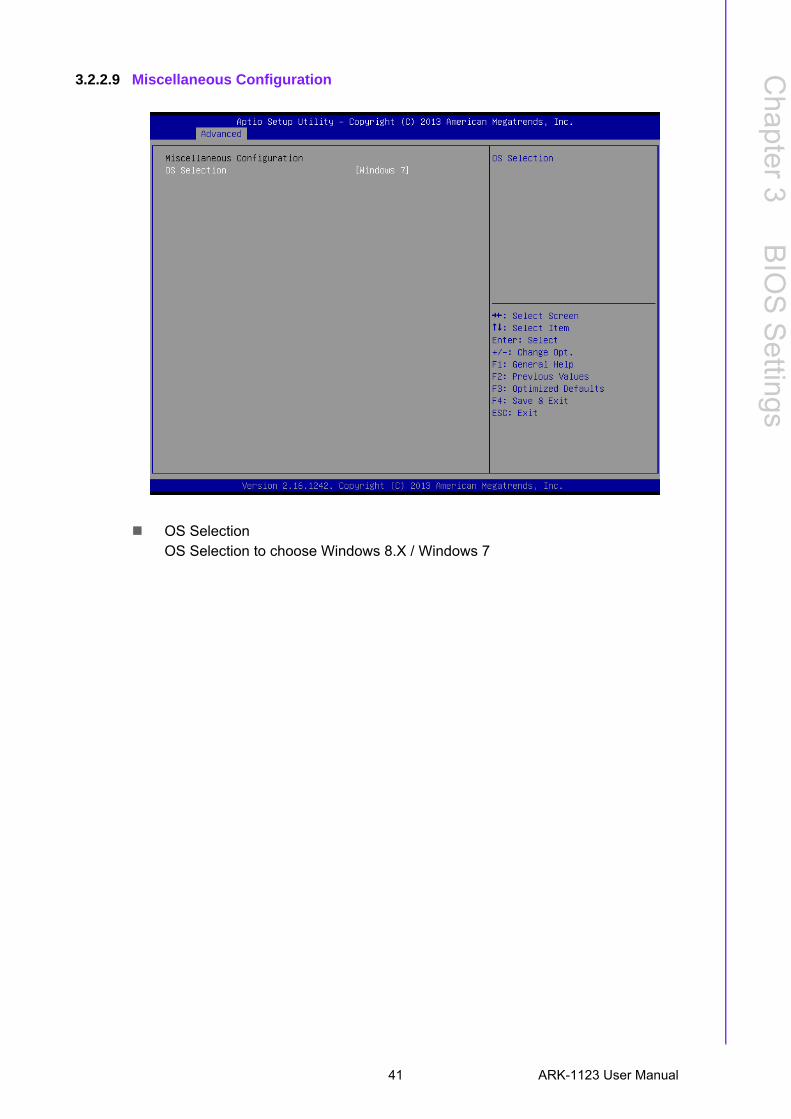
3.2.2.9 Miscellaneous Configuration
OS SelectionOS Selection to choose Windows 8.X / Windows 7
41 ARK-1123 User Manual
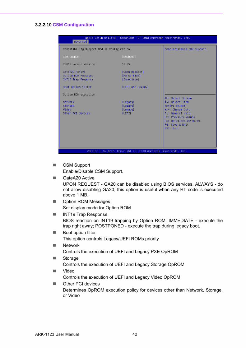
3.2.2.10 CSM Configuration
CSM SupportEnable/Disable CSM Support.
GateA20 ActiveUPON REQUEST - GA20 can be disabled using BIOS services. ALWAYS - donot allow disabling GA20; this option is useful when any RT code is executedabove 1 MB.
Option ROM MessagesSet display mode for Option ROM
INT19 Trap ResponseBIOS reaction on INT19 trapping by Option ROM: IMMEDIATE - execute thetrap right away; POSTPONED - execute the trap during legacy boot.
Boot option filterThis option controls Legacy/UEFI ROMs priority
NetworkControls the execution of UEFI and Legacy PXE OpROM
StorageControls the execution of UEFI and Legacy Storage OpROM
VideoControls the execution of UEFI and Legacy Video OpROM
Other PCI devicesDetermines OpROM execution policy for devices other than Network, Storage,or Video
ARK-1123 User Manual 42
Chapter 3
BIO
S S
ettings
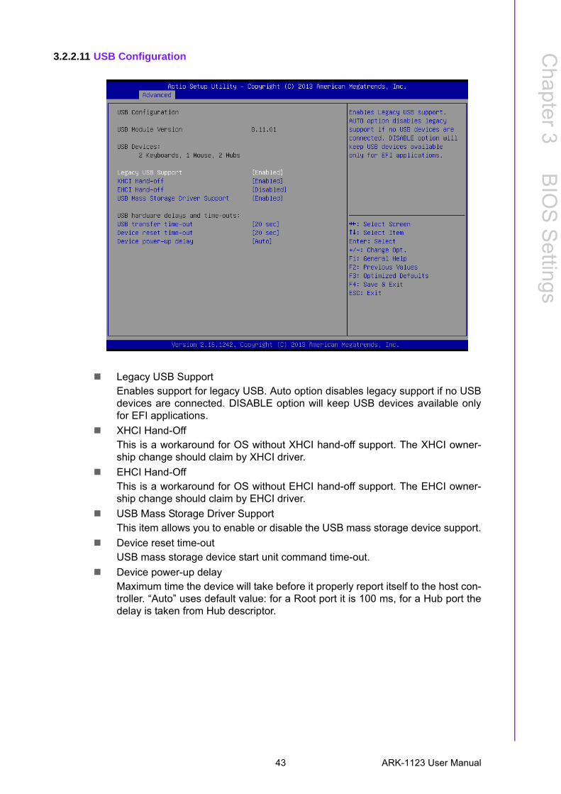
3.2.2.11 USB Configuration
Legacy USB SupportEnables support for legacy USB. Auto option disables legacy support if no USBdevices are connected. DISABLE option will keep USB devices available onlyfor EFI applications.
XHCI Hand-OffThis is a workaround for OS without XHCI hand-off support. The XHCI owner-ship change should claim by XHCI driver.
EHCI Hand-OffThis is a workaround for OS without EHCI hand-off support. The EHCI owner-ship change should claim by EHCI driver.
USB Mass Storage Driver SupportThis item allows you to enable or disable the USB mass storage device support.
Device reset time-outUSB mass storage device start unit command time-out.
Device power-up delayMaximum time the device will take before it properly report itself to the host con-troller. “Auto” uses default value: for a Root port it is 100 ms, for a Hub port thedelay is taken from Hub descriptor.
43 ARK-1123 User Manual
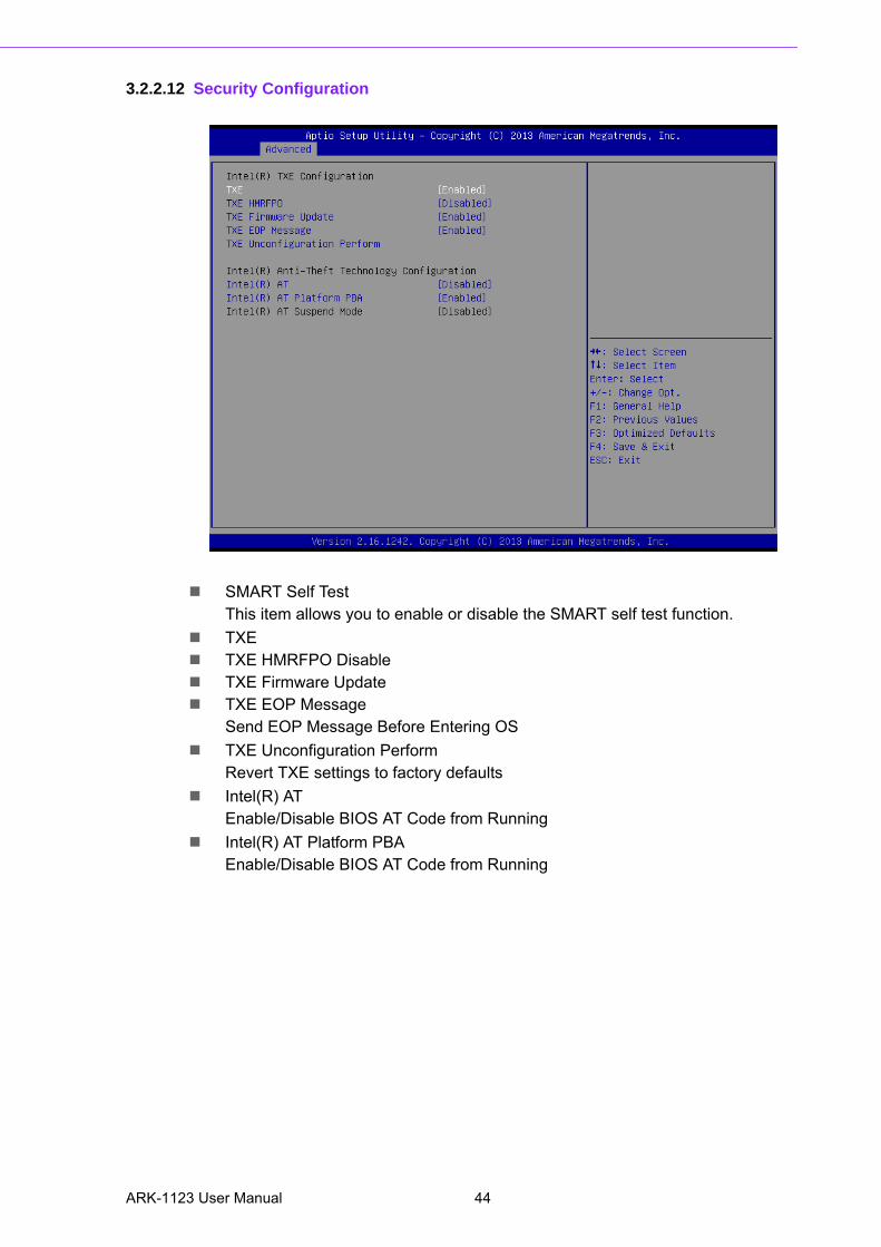
3.2.2.12 Security Configuration
SMART Self Test This item allows you to enable or disable the SMART self test function.
TXE TXE HMRFPO Disable TXE Firmware Update TXE EOP Message
Send EOP Message Before Entering OS
TXE Unconfiguration PerformRevert TXE settings to factory defaults
Intel(R) ATEnable/Disable BIOS AT Code from Running
Intel(R) AT Platform PBAEnable/Disable BIOS AT Code from Running
ARK-1123 User Manual 44
Chapter 3
BIO
S S
ettings
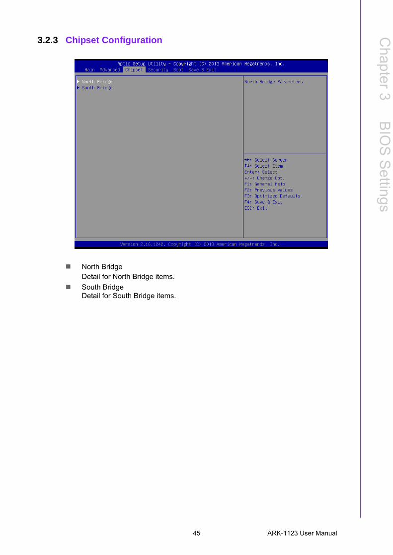
3.2.3 Chipset Configuration
North BridgeDetail for North Bridge items.
South BridgeDetail for South Bridge items.
45 ARK-1123 User Manual
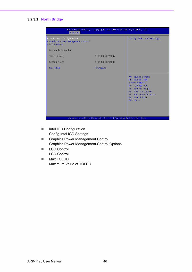
3.2.3.1 North Bridge
Intel IGD ConfigurationConfig Intel IGD Settings.
Graphics Power Management ControlGraphics Power Management Control Options
LCD ControlLCD Control
Max TOLUDMaximum Value of TOLUD
ARK-1123 User Manual 46
Chapter 3
BIO
S S
ettings
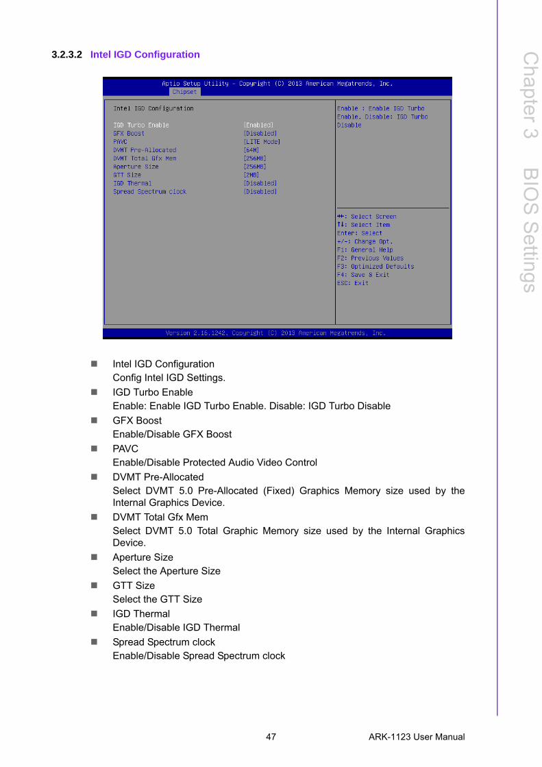
3.2.3.2 Intel IGD Configuration
Intel IGD ConfigurationConfig Intel IGD Settings.
IGD Turbo EnableEnable: Enable IGD Turbo Enable. Disable: IGD Turbo Disable
GFX BoostEnable/Disable GFX Boost
PAVCEnable/Disable Protected Audio Video Control
DVMT Pre-AllocatedSelect DVMT 5.0 Pre-Allocated (Fixed) Graphics Memory size used by theInternal Graphics Device.
DVMT Total Gfx MemSelect DVMT 5.0 Total Graphic Memory size used by the Internal GraphicsDevice.
Aperture SizeSelect the Aperture Size
GTT SizeSelect the GTT Size
IGD ThermalEnable/Disable IGD Thermal
Spread Spectrum clockEnable/Disable Spread Spectrum clock
47 ARK-1123 User Manual
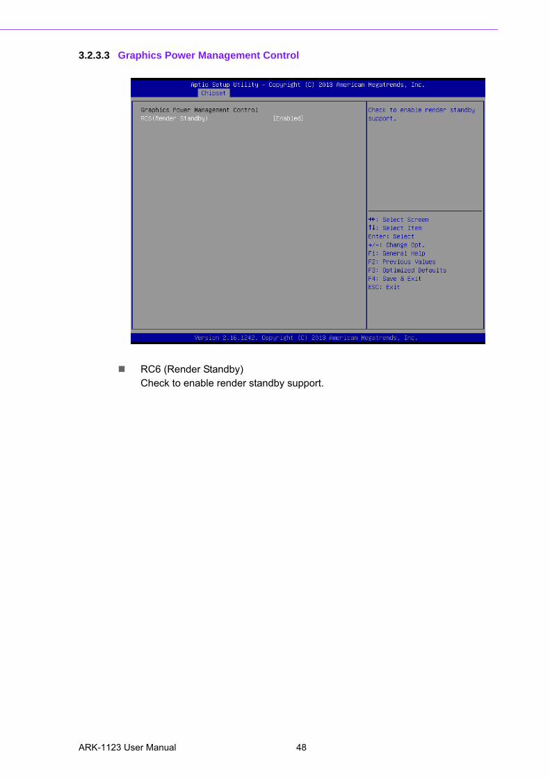
3.2.3.3 Graphics Power Management Control
RC6 (Render Standby)Check to enable render standby support.
ARK-1123 User Manual 48
Chapter 3
BIO
S S
ettings
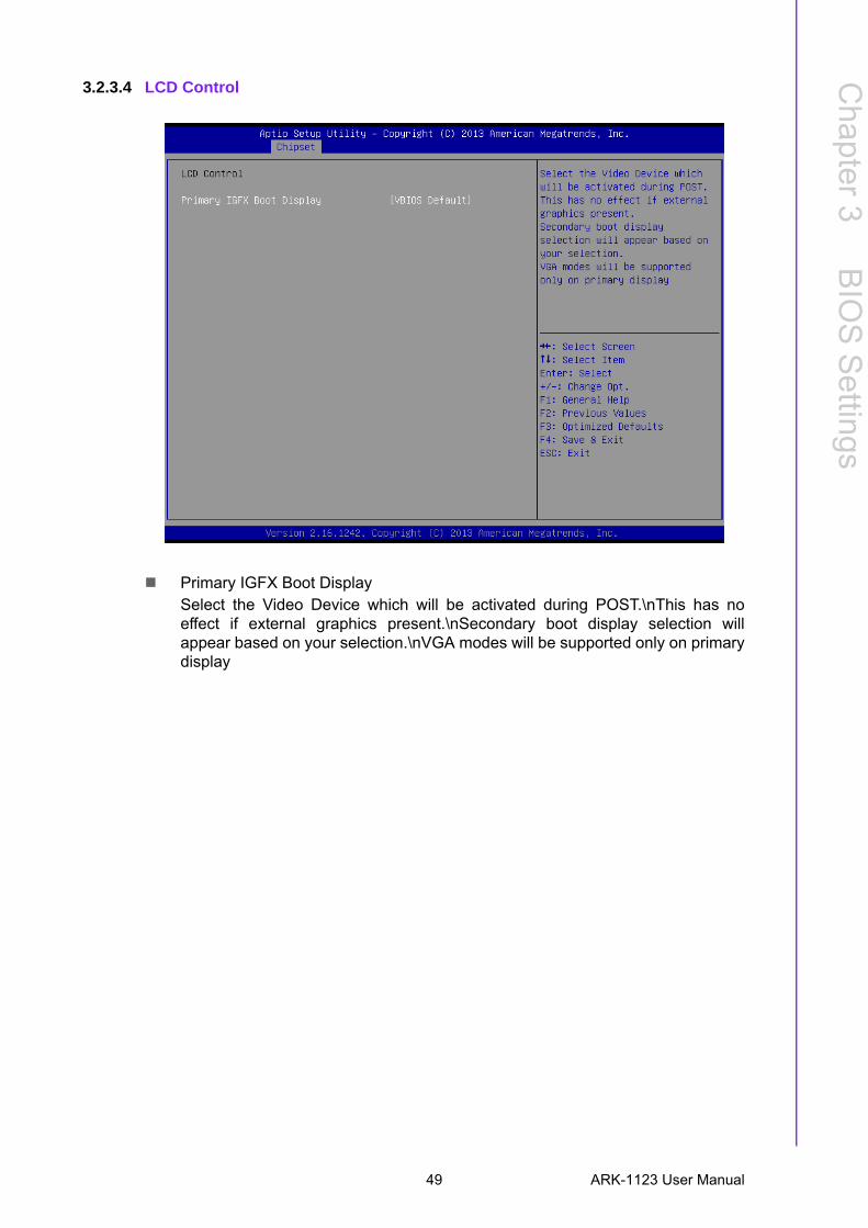
3.2.3.4 LCD Control
Primary IGFX Boot DisplaySelect the Video Device which will be activated during POST.\nThis has noeffect if external graphics present.\nSecondary boot display selection willappear based on your selection.\nVGA modes will be supported only on primarydisplay
49 ARK-1123 User Manual
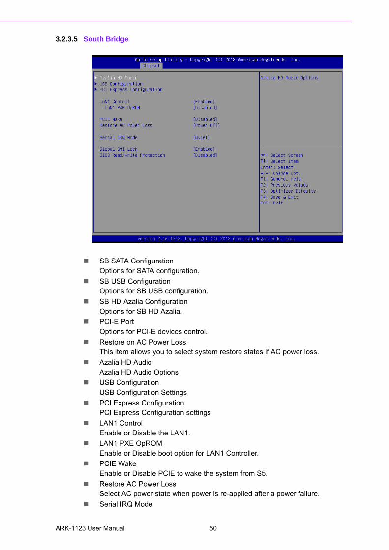
3.2.3.5 South Bridge
SB SATA ConfigurationOptions for SATA configuration.
SB USB ConfigurationOptions for SB USB configuration.
SB HD Azalia ConfigurationOptions for SB HD Azalia.
PCI-E PortOptions for PCI-E devices control.
Restore on AC Power LossThis item allows you to select system restore states if AC power loss.
Azalia HD AudioAzalia HD Audio Options
USB ConfigurationUSB Configuration Settings
PCI Express ConfigurationPCI Express Configuration settings
LAN1 ControlEnable or Disable the LAN1.
LAN1 PXE OpROMEnable or Disable boot option for LAN1 Controller.
PCIE WakeEnable or Disable PCIE to wake the system from S5.
Restore AC Power LossSelect AC power state when power is re-applied after a power failure.
Serial IRQ Mode
ARK-1123 User Manual 50
Chapter 3
BIO
S S
ettings
Configure Serial IRQ Mode.
Global SMI LockEnable or Disable SMI lock.
BIOS Read/Write ProtectionEnable or Disable BIOS SPI region read/write protect.
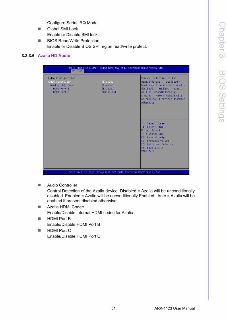
3.2.3.6 Azalia HD Audio
Audio ControllerControl Detection of the Azalia device. Disabled = Azalia will be unconditionallydisabled. Enabled = Azalia will be unconditionally Enabled. Auto = Azalia will beenabled if present disabled otherwise.
Azalia HDMI CodecEnable/Disable internal HDMI codec for Azalia
HDMI Port BEnable/Disable HDMI Port B
HDMI Port CEnable/Disable HDMI Port C
51 ARK-1123 User Manual
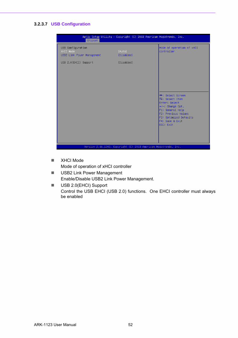
3.2.3.7 USB Configuration
XHCI ModeMode of operation of xHCI controller
USB2 Link Power ManagementEnable/Disable USB2 Link Power Management.
USB 2.0(EHCI) SupportControl the USB EHCI (USB 2.0) functions. One EHCI controller must alwaysbe enabled
ARK-1123 User Manual 52
Chapter 3
BIO
S S
ettings
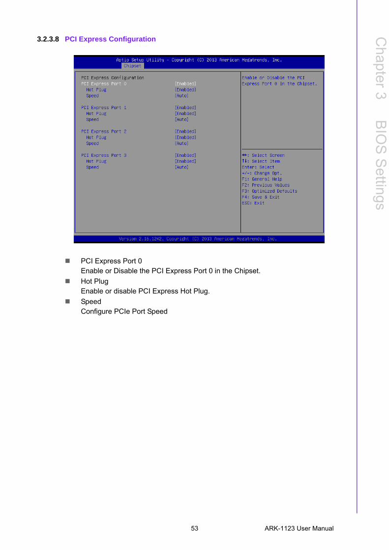
3.2.3.8 PCI Express Configuration
PCI Express Port 0Enable or Disable the PCI Express Port 0 in the Chipset.
Hot PlugEnable or disable PCI Express Hot Plug.
SpeedConfigure PCIe Port Speed
53 ARK-1123 User Manual
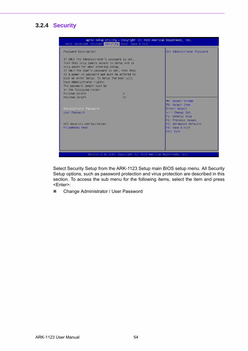
3.2.4 Security
Select Security Setup from the ARK-1123 Setup main BIOS setup menu. All SecuritySetup options, such as password protection and virus protection are described in thissection. To access the sub menu for the following items, select the item and press<Enter>:
Change Administrator / User Password
ARK-1123 User Manual 54
Chapter 3
BIO
S S
ettings
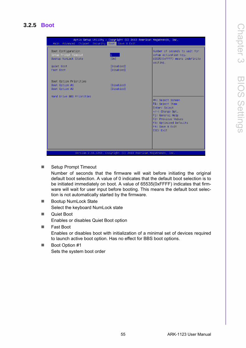
3.2.5 Boot
Setup Prompt TimeoutNumber of seconds that the firmware will wait before initiating the originaldefault boot selection. A value of 0 indicates that the default boot selection is tobe initiated immediately on boot. A value of 65535(0xFFFF) indicates that firm-ware will wait for user input before booting. This means the default boot selec-tion is not automatically started by the firmware.
Bootup NumLock StateSelect the keyboard NumLock state
Quiet BootEnables or disables Quiet Boot option
Fast BootEnables or disables boot with initialization of a minimal set of devices requiredto launch active boot option. Has no effect for BBS boot options.
Boot Option #1Sets the system boot order
55 ARK-1123 User Manual
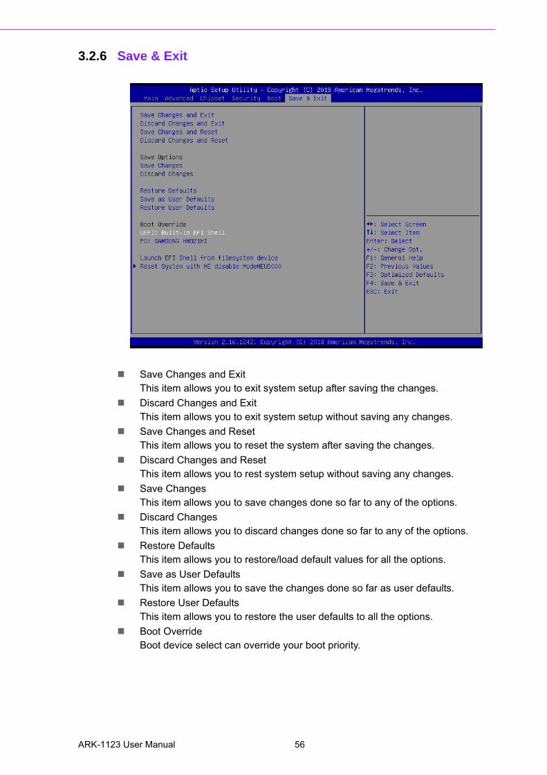
3.2.6 Save & Exit
Save Changes and ExitThis item allows you to exit system setup after saving the changes.
Discard Changes and ExitThis item allows you to exit system setup without saving any changes.
Save Changes and ResetThis item allows you to reset the system after saving the changes.
Discard Changes and ResetThis item allows you to rest system setup without saving any changes.
Save ChangesThis item allows you to save changes done so far to any of the options.
Discard ChangesThis item allows you to discard changes done so far to any of the options.
Restore DefaultsThis item allows you to restore/load default values for all the options.
Save as User DefaultsThis item allows you to save the changes done so far as user defaults.
Restore User DefaultsThis item allows you to restore the user defaults to all the options.
Boot OverrideBoot device select can override your boot priority.
ARK-1123 User Manual 56

Appendix A
A WDT & GPIO Sample Code
A.1 Watchdog Timer Sample CodeWatchdog function:
;The SCH3114 Runtime base I/O address is A00h
;Setting WatchDog time value location at offset 66h
;If set value "0", it is mean disable WatchDog function.
Superio_GPIO_Port = A00h
mov dx,Superio_GPIO_Port + 66h
mov al,00h
out dx,al
.model small
.486p
.stack 256
.data
SCH3114_IO EQU A00h
.code
org 100h
.STARTup
;====================================================
;47H
;enable WDT function bit [0]=0Ch
;====================================================
mov dx,SCH3114_IO + 47h
mov al,0Ch
out dx,al
;====================================================
;65H
;bit [1:0]=Reserved
;bit [6:2]Reserve=00000
;bit [7] WDT time-out Value Units Select
;Minutes=0 (default) Seconds=1
;====================================================
mov dx,SCH3114_IO + 65h ;
mov al,080h
out dx,al
;====================================================
;66H
;WDT timer time-out value
;bit[7:0]=0~255
;====================================================
mov dx,SCH3114_IO + 66h
mov al,01h
out dx,al
;====================================================
;bit[0] status bit R/W
;WD timeout occurred =1
ARK-1123 User Manual 58
Appendix A
WD
T &
GP
IOS
ample
Code
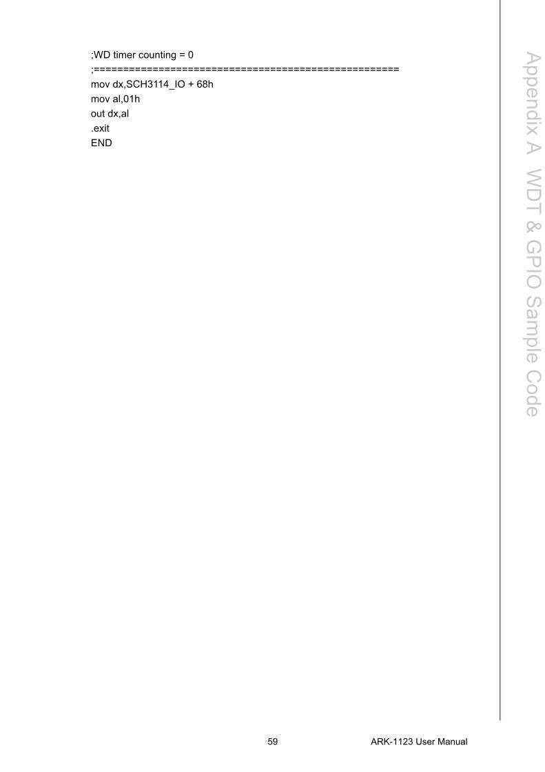
;WD timer counting = 0
;====================================================
mov dx,SCH3114_IO + 68h
mov al,01h
out dx,al
.exit
END
59 ARK-1123 User Manual

ARK-1123 User Manual 60

www.advantech.comPlease verify specifications before quoting. This guide is intended for referencepurpOS only.All product specifications are subject to change without notice.No part of this publication may be reproduced in any form or by any means,electronic, photocopying, recording or otherwise, without prior written permis-sion of the publisher.All brand and product names are trademarks or registered trademarks of theirrespective companies.© Advantech Co., Ltd. 2014


![Family guy cast-1123[1].jpg](https://img.pdfslide.us/doc/110x75/55a5bc271a28abd2368b4649/family-guy-cast-11231jpg.jpg)