Embed Size (px)
Citation preview

User Manual
APAX-5620
XScale CPU Module

CopyrightThe documentation and the software included with this product are copyrighted 2013by Advantech Co., Ltd. All rights are reserved. Advantech Co., Ltd. reserves the rightto make improvements in the products described in this manual at any time withoutnotice. No part of this manual may be reproduced, copied, translated or transmittedin any form or by any means without the prior written permission of Advantech Co.,Ltd. Information provided in this manual is intended to be accurate and reliable. How-ever, Advantech Co., Ltd. assumes no responsibility for its use, nor for any infringe-ments of the rights of third parties, which may result from its use.
AcknowledgementsIntel and Pentium are trademarks of Intel Corporation.
Microsoft Windows and MS-DOS are registered trademarks of Microsoft Corp.
All other product names or trademarks are properties of their respective owners.
Product Warranty (2 years)Advantech warrants to you, the original purchaser, that each of its products will befree from defects in materials and workmanship for two years from the date of pur-chase.
This warranty does not apply to any products which have been repaired or altered bypersons other than repair personnel authorized by Advantech, or which have beensubject to misuse, abuse, accident or improper installation. Advantech assumes noliability under the terms of this warranty as a consequence of such events.
Because of Advantech’s high quality-control standards and rigorous testing, most ofour customers never need to use our repair service. If an Advantech product is defec-tive, it will be repaired or replaced at no charge during the warranty period. For out-of-warranty repairs, you will be billed according to the cost of replacement materials,service time and freight. Please consult your dealer for more details.
If you think you have a defective product, follow these steps:
1. Collect all the information about the problem encountered. (For example, CPU speed, Advantech products used, other hardware and software used, etc.) Note anything abnormal and list any onscreen messages you get when the problem occurs.
2. Call your dealer and describe the problem. Please have your manual, product, and any helpful information readily available.
3. If your product is diagnosed as defective, obtain an RMA (return merchandize authorization) number from your dealer. This allows us to process your return more quickly.
4. Carefully pack the defective product, a fully-completed Repair and Replacement Order Card and a photocopy proof of purchase date (such as your sales receipt) in a shippable container. A product returned without proof of the purchase date is not eligible for warranty service.
5. Write the RMA number visibly on the outside of the package and ship it prepaid to your dealer.
Edition 1.4
Printed in Taiwan October 2013
APAX-5620 User Manual ii

Declaration of Conformity
CE
This product has passed the CE test for environmental specifications when shieldedcables are used for external wiring. We recommend the use of shielded cables. Thiskind of cable is available from Advantech. Please contact your local supplier forordering information.
FCC Class A
Note: This equipment has been tested and found to comply with the limits for a ClassA digital device, pursuant to part 15 of the FCC Rules. These limits are designed toprovide reasonable protection against harmful interference when the equipment isoperated in a commercial environment. This equipment generates, uses, and canradiate radio frequency energy and, if not installed and used in accordance with theinstruction manual, may cause harmful interference to radio communications. Opera-tion of this equipment in a residential area is likely to cause harmful interference inwhich case the user will be required to correct the interference at his own expense.
Technical Support and Assistance1. Visit the Advantech web site at www.advantech.com/support where you can find
the latest information about the product.2. Contact your distributor, sales representative, or Advantech's customer service
center for technical support if you need additional assistance. Please have the following information ready before you call:– Product name and serial number– Description of your peripheral attachments– Description of your software (OS, version, application software, etc.)– A complete description of the problem– The exact wording of any error messages
Safety Precaution - Static ElectricityFollow these simple precautions to protect yourself from harm and the products fromdamage.
To avoid electrical shock, always disconnect the power from your PC chassis before you work on it. Don't touch any components on the CPU card or other cards while the PC is on.
Disconnect power before making any configuration changes. The sudden rush ofpower as you connect a jumper or install a card may damage sensitive electroniccomponents.
iii APAX-5620 User Manual

Safety Instructions1. Read these safety instructions carefully.2. Keep this User Manual for later reference.3. Disconnect this equipment from any AC outlet before cleaning. Use a damp
cloth. Do not use liquid or spray detergents for cleaning.4. For plug-in equipment, the power outlet socket must be located near the equip-
ment and must be easily accessible.5. Keep this equipment away from humidity.6. Put this equipment on a reliable surface during installation. Dropping it or letting
it fall may cause damage.7. The openings on the enclosure are for air convection. Protect the equipment
from overheating. DO NOT COVER THE OPENINGS.8. Make sure the voltage of the power source is correct before connecting the
equipment to the power outlet.9. Position the power cord so that people cannot step on it. Do not place anything
over the power cord.10. All cautions and warnings on the equipment should be noted.11. If the equipment is not used for a long time, disconnect it from the power source
to avoid damage by transient overvoltage.12. Never pour any liquid into an opening. This may cause fire or electrical shock.13. Never open the equipment. For safety reasons, the equipment should be
opened only by qualified service personnel.14. If one of the following situations arises, get the equipment checked by service
personnel:15. The power cord or plug is damaged.16. Liquid has penetrated into the equipment.17. The equipment has been exposed to moisture.18. The equipment does not work well, or you cannot get it to work according to the
user's manual.19. The equipment has been dropped and damaged.20. The equipment has obvious signs of breakage.21. DO NOT LEAVE THIS EQUIPMENT IN AN ENVIRONMENT WHERE THE
STORAGE TEMPERATURE MAY GO BELOW -20° C (-4° F) OR ABOVE 60° C (140° F). THIS COULD DAMAGE THE EQUIPMENT. THE EQUIPMENT SHOULD BE IN A CONTROLLED ENVIRONMENT.
22. CAUTION: DANGER OF EXPLOSION IF BATTERY IS INCORRECTLY REPLACED. REPLACE ONLY WITH THE SAME OR EQUIVALENT TYPE RECOMMENDED BY THE MANUFACTURER, DISCARD USED BATTERIES ACCORDING TO THE MANUFACTURER'S INSTRUCTIONS.
23. The sound pressure level at the operator's position according to IEC 704-1:1982 is no more than 70 dB (A).
DISCLAIMER: This set of instructions is given according to IEC 704-1. Advantechdisclaims all responsibility for the accuracy of any statements contained herein.
APAX-5620 User Manual iv

Chapter 1 Overview...............................................11.1 Introduction ............................................................................................... 21.2 System Architecture .................................................................................. 31.3 Features .................................................................................................... 5
1.3.1 Battery Backup RAM..................................................................... 51.3.2 CF Slot for Data Storage............................................................... 61.3.3 VGA Display.................................................................................. 61.3.4 USB Port ....................................................................................... 71.3.5 Ethernet Port................................................................................. 81.3.6 RS-485 & CAN Bus Communication Ability .................................. 91.3.7 Terminal Resistor Settings.......................................................... 101.3.8 Controller ID Settings.................................................................. 101.3.9 Real-Time Clock (RTC)............................................................... 10
Chapter 2 Product Specifications......................112.1 CPU Modules .......................................................................................... 12
2.1.1 APAX-5620 ................................................................................. 122.1.2 APAX-5620 Dimensions ............................................................. 13
2.2 Power Supply Modules ........................................................................... 142.2.1 APAX-5343E............................................................................... 14
Chapter 3 Mechanical Installation .....................153.1 Mounting ................................................................................................ 16
3.1.1 DIN-rail Mounting ........................................................................ 163.1.2 Wall (Panel) Mounting................................................................. 18
Chapter 4 Error Handling and Diagnostics.......254.1 Error Handling and Diagnostics .............................................................. 26A.1 RS-485 Network ..................................................................................... 28A.2 Basic Network Layout ............................................................................. 28
A.2.1 Line Termination ......................................................................... 30Figure A.1 Signal Distortion ....................................................... 30Figure A.2 Termination Resistor Locations ................................ 30
A.3 RS-485 Data Flow Control ...................................................................... 32Figure A.3 RS-485 Data Flow Control with RTS ........................ 32
v APAX-5620 User Manual

APAX-5620 User Manual vi

Chapter 1
1 Overview
1.1 IntroductionAPAX-5620 is a compact controller (CPU module) with XScale PXA270 CPU andWindows CE.NET operating system. By connecting with different APAX-5000 I/Omodules, APAX-5620 can execute control tasks for various industrial control andautomation applications.
Due to the low power consumption, APAX-5620 doesn't require any fan in the mech-anism, giving better reliability. The operating system is installed in the internal flash.Therefore, no extra external HD or CF is required for the operating system and appli-cation programs. Besides, APAX-5620 provides an internal CF slot for data storage.
Advantech provides two versions of the APAX-5620:
APAX-5620CE: It performs as a standalone controller when it connects with APAX-5000 I/O modules. Through built-in utility, programmers can configure related hard-ware settings for the APAX-5000 I/O modules. Then, programmers can build theirown application programs by Advantech .NET class libraries to control APAX-5000 I/O modules under Microsoft Visual Studio .NET programming environment.
APAX-5620KW: It can be operated in two ways. The first way is that APAX-5620KWcan be a standalone controller, just like APAX-5620CE, when it connects with APAX-5000 I/O modules. The difference is that APAX-5620KW programming environmentis KW MultiProg, which is IEC-61131-3 softlogic programming tool that PLC program-mers are familiar with. KW MultiProg supports Instruction List (IL), Structure Text(ST), Function Block Diagram (FBD), Sequential Function Chart (SFC) and LadderDiagram (LD).
After programmers complete their program, it can be downloaded to APAX-5620KW,and the built-in KW ProConOS kernel will execute the control program. KW MultiProgand ProConOS feature real-time I/O control performance (guaranteed executiontime), which is very important for many control applications. Since APAX-5620KW isequipped with the KW softlogic environment, it becomes a Programmable Automa-tion Controller (PAC).
The second operation way for APAX-5620KW is that it can work with other CPU mod-ules, such as APAX-5570XPE/5571XPE. Combining APAX-5620KW with anotherCPU module provides dual CPU architecture to the control system. For this kind ofarchitecture, APAX-5620 focuses on the I/O control for APAX-5000 I/O modules, fea-turing real-time control performance; while another CPU module (usually with higherCPU grade) executes other tasks which needs higher computing ability, such as HMI/SCADA, database, communication, recipe, etc. If that CPU module has anythingwrong and become hang, APAX-5620KW can continue executing the I/O controltasks, and this ensures the system reliability.
Note! Please refer to APAX-5620 software manual for how to configure the hardware and program under Microsoft Visual Studio .NET or KW MultiProg.
APAX-5620 User Manual 2

Chapter 1
Overview
APAX-5620 provides two serial (RS-485) ports, two CAN ports, and two ethernetports to communicate with other devices. Programmers can leverage the communi-cation ability through Modbus/RTU master/slave and Modbus/TCP server/client.APAX-5620 also provides one VGA port and one USB port, so it can be connected toAdvantech Industrial Monitor (FPM) or standard monitor with VGA input. Touch func-tionality is connected via USB. Besides, devices such as mouse, keyboard, massstorage can be connected via the USB interface.
1.2 System ArchitectureAPAX-5620CE and APAX-5620KW can play as standalone controller. It needs to beinserted on the APAX-5002 backplane to get power. By assembling with other APAX-5000 I/O modules by backplanes, APAX-5620 can communicate with other APAX-5000 I/O modules through the backplanes Refer to Section 3.1 for the assemblyoperation.
As described in previous section, APAX-5620KW can also work with another CPUmodule to deliver dual CPU architecture. Take APAX-5570XPE/5571XPE as exam-ple, APAX-5620KW inserted on one of the PCI slot on APAX-5570XPE/XPE can getpower from APAX-5570XPE/5571XPE (We strongly suggest inserting APAX-5620KW on the first slot to have better ventilation.) Then, APAX-5620KW can com-municate with other stacked APAX-5000 I/O modules through the backplanes.
Note! With expansion port on backplanes, users can build a remote expansion architecture, remaining fast local-bus data transmission speed. Refer to Section 3.1.1 for how to build remote expansion.
Warning! If there are multiple controllers (including couplers) in the same system, be SURE all these controller have different controller ID. (APAX-557x use utility to configure its controller ID, while APAX-5620 uses the switch to define the controller ID)
3 APAX-5620 User Manual

APAX-5620 supports backup function. To leverage this functionality, two CPU mod-ules (controllers), with the same control program, are installed in one system. Afterboth controllers are enabled to have backup function, the APAX-5000 system willautomatically delegate one of the two controllers as the master controller.
The master controller will run the control program to execute the control process,while another controller (the backup controller) is put on standby. The master control-ler will periodically send living message to the backup controller. If the backup con-troller dose not receive living message from master controller over 500 milliseconds,it will automatically become master controller and take the control responsibility andrestarts the control process execution. The maximum operation time for the backupcontroller to become master controller (the take over time) won't be greater than 1.5second.
Changing master controller means there is something wrong for the previous mastercontroller. Therefore, engineers can check or change the previous master controllerwith a new one and enable it to have backup functionality, becoming a secondbackup controller. Then if the new master controller fails again, the second backupcontroller will automatically take the control responsibility.
This mechanism ensures the control system will continuously run the control pro-cess. And the system won’t be stopped even if controller fails.
Note! If there are more than two controllers (including couplers) in one system, the real-time performance of the I/O process at less than 1 millisecond cannot be guaranteed.
Warning! When there are more than two controllers in one system, only one controller is allowed to control I/O modules. For other controllers and couplers, they can ONLY perform read operations.
APAX-5620 User Manual 4
Chapter 1
Overview
1.3 Features
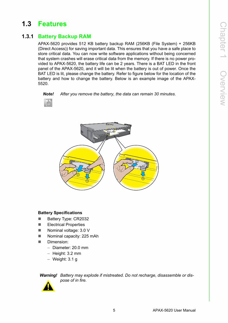
1.3.1 Battery Backup RAM APAX-5620 provides 512 KB battery backup RAM (256KB (File System) + 256KB(Direct Access)) for saving important data. This ensures that you have a safe place tostore critical data. You can now write software applications without being concernedthat system crashes will erase critical data from the memory. If there is no power pro-vided to APAX-5620, the battery life can be 2 years. There is a BAT LED in the frontpanel of the APAX-5620, and it will be lit when the battery is out of power. Once theBAT LED is lit, please change the battery. Refer to figure below for the location of thebattery and how to change the battery. Below is an example image of the APAX-5520.
Battery Specifications
Battery Type: CR2032 Electrical Properties Nominal voltage: 3.0 V Nominal capacity: 225 mAh Dimension:
– Diameter: 20.0 mm– Height: 3.2 mm– Weight: 3.1 g
Note! After you remove the battery, the data can remain 30 minutes.
Warning! Battery may explode if mistreated. Do not recharge, disassemble or dis-pose of in fire.
5 APAX-5620 User Manual

1.3.2 CF Slot for Data StorageAPAX-5620 has built-in Microsoft Windows CE.NET operating system. The operatingsystem is installed in the flash. Your application program will also be stored on theflash. However, we strongly suggest not saving data to the flash. Repeat reading andwriting will serious damage the flash life. APAX-5620 delivers an internal CF slot fordata storage. It only supports FAT, and the CF card size can be up to 1 GB. Refer tofigure below for the location of CF slot and how to insert/plug CF.
1.3.3 VGA Display APAX-5620 provides VGA controller for a high resolution interface. It supports 640 x480 @ 16 bpp. The VGA port delivers standard DB-15 connector. The VGA displayfunctionality can be disabled by the DIP switch on the PCB board. Refer to figurebelow for the location of the DIP switch and VGA port pin assignments.
DIP Switch Settings(SW3) VGA Function
Enabled
Disabled
APAX-5620 User Manual 6

Chapter 1
Overview
1.3.4 USB PortThe APAX-5620 provides one connectors of USB interfaces. The USB interface com-plies with USB EHCI, Rev. 1.1 compliant. The USB socket is type A socket (miniUSB). In order to connect with many other USB devices, APAX-5620 provides exter-nal transfer cable to transfer mini USB to standard USB in the accessory.
Pin Assignment Description
1 Red Analog Red Output
2 Green Analog Green Output
3 Blue Analog Blue Output
4 N/C not used
5 GND Ground
6 GND Ground
7 GND Ground
8 GND Ground
9 N/C not used
10 GND Ground
11 N/C not used
12 N/C not used
13 H-Sync Analog Horizontal Sync
14 V-Sync Analog Vertial Sync
15 N/C not used
Note! For APAX-5620CE, the default setting for the DIP switch is VGA display enabled. For APAX-5620KW, the default setting for the DIP switch is VGA display disabled. If you enable the VGA port and wants to run your own application programs on APAX-5620KW, be very careful since bad program may cause a system crash owing to memory leakage.
5
15
1
11
10 6
Pin Assignment Description
1 VBUS Power(+5V)
2 D- Data-
3 D+ Data +
4 GND Ground
7 APAX-5620 User Manual

1.3.5 Ethernet PortThe APAX-5620 is equipped with one Ethernet port which is fully compliant with IEEE802.3u 10/100Mbpst. The Ethernet port provides a standard RJ-45 with upper leftLED indicator on the front side showing Link/Activity (Off: Not Link, Green and Flash:Link and Activity), and lower left LED indicator showing LAN speed (Orange: 100Mbps, Off: 10 Mbps). Refer to figure below for Ethernet port pin assignment.
Pin Assignment Description
1 TD + Transmit +
2 TD - Transmit -
3 RD + Receive +
4 N/C not used
5 N/C not used
6 RD - Receive -
7 N/C not used
8 N/C not used
Note! The Ethernet port is only used in LAN, not for connection to telecommu-nication circuits.
APAX-5620 User Manual 8

Chapter 1
Overview
1.3.6 RS-485 & CAN Bus Communication AbilityAPAX-5620 delivers one isolated RS-485 serial communication interface port to con-nect with other devices. APAX-5620 RS-485 interface supports auto data flow controlfunctionality: it automatically detects the direction of incoming data and switches itstransmission direction accordingly. So no handshaking signal (e.g. RTS signal) isnecessary. This lets you conveniently build an RS-485 network with just two wires.
APAX-5620 provides 2-ports CAN bus communication interface as well, so that cus-tomers can control the CAN devices through them.
A terminal resistor is needed for long distance transmission or device matching.
Pin Assignment Description
1 CAN1H CAN1H
2 CAN1L CAN1L
3 IGND Ground
4 CAN2H CAN2H
5 CAN2L CAN2L
6 IGND Ground
7 N/C Reserved
8 DATA0+ DATA0+
9 DATA0- DATA0-
10 IGND Ground
11 DATA1+ DATA1+
12 DATA1- DATA1-
13 IGND Ground
Note! Refer to Appendix A for more detailed information about RS-485 communication.
9 APAX-5620 User Manual

1.3.7 Terminal Resistor Settings
1.3.8 Controller ID SettingsAPAX-5620 supports backup function and it has to be configured to the different IDaddress. For ID setting, please see below.
1.3.9 Real-Time Clock (RTC)APAX-5620 delivers built-in real-time clock, which programmers can use it in theirapplication programs. When the power is loss, the RTC can still run using the powerfrom battery which has been described in section 1.3.1.
Pin ON OFF
1 120 Ohm for CAN1 None
2 120 Ohm for CAN2 None
3 300Ohm for DATA0 None
4 300Ohm for DATA1 None
Note! For CAN bus communication, it will be better to add the terminal resistor at one side for transmission stability.
ID Address Settings(SW1) ID Address
ID:0
ID:1
APAX-5620 User Manual 10

Chapter 2
2 Product Specifications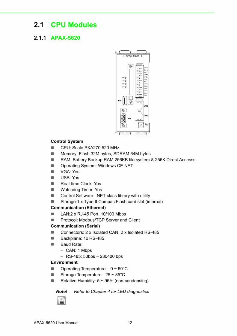
2.1 CPU Modules
2.1.1 APAX-5620
Control System
CPU: Scale PXA270 520 MHz Memory: Flash 32M bytes, SDRAM 64M bytes RAM: Battery Backup RAM 256KB file system & 256K Direct Accesss Operating System: Windows CE.NET VGA: Yes USB: Yes Real-time Clock: Yes Watchdog Timer: Yes Control Software: .NET class library with utility Storage:1 x Type II CompactFlash card slot (internal)Communication (Ethernet)
LAN:2 x RJ-45 Port, 10/100 Mbps Protocol: Modbus/TCP Server and ClientCommunication (Serial)
Connectors: 2 x Isolated CAN, 2 x Isolated RS-485 Backplane: 1x RS-485 Baud Rate:
– CAN: 1 Mbps– RS-485: 50bps ~ 230400 bps
Environment
Operating Temperature: 0 ~ 60°C Storage Temperature: -25 ~ 85°C Relative Humidity: 5 ~ 95% (non-condensing)
Note! Refer to Chapter 4 for LED diagnostics
APAX-5620 User Manual 12
Chapter 2
ProductS
pecifications
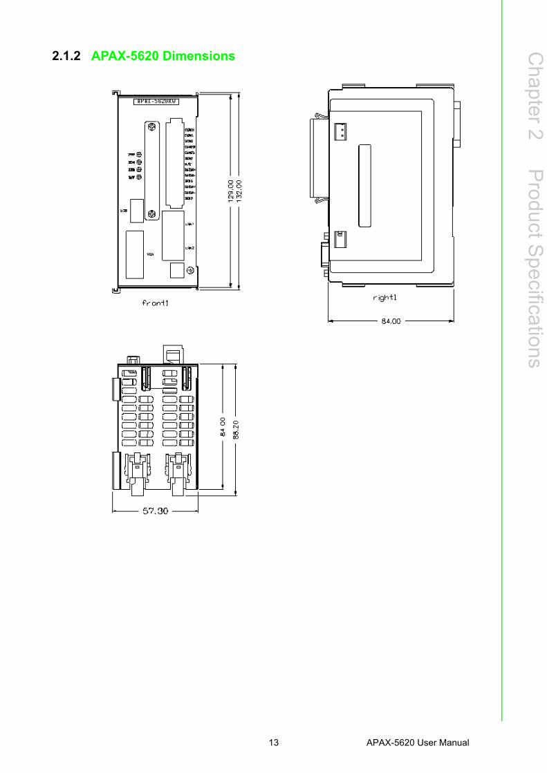
2.1.2 APAX-5620 Dimensions
13 APAX-5620 User Manual
2.2 Power Supply Modules
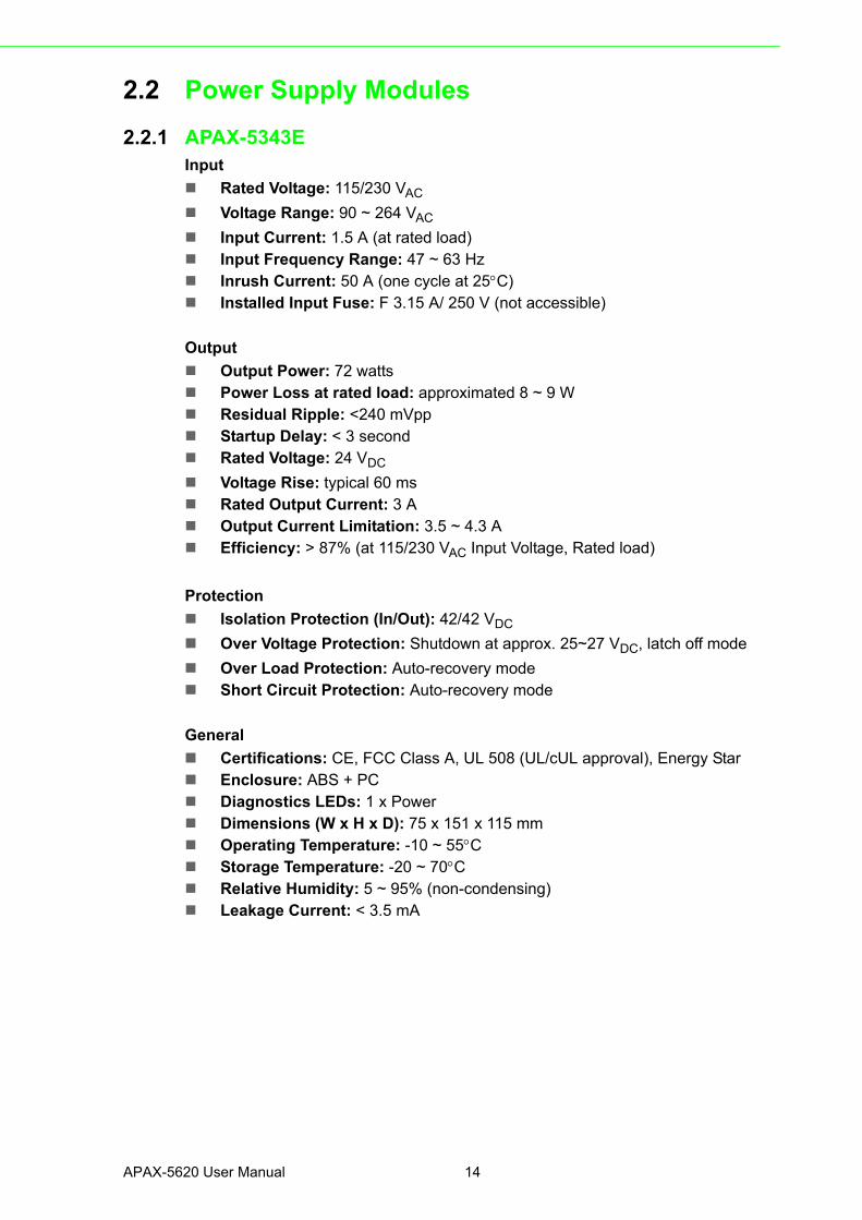
2.2.1 APAX-5343EInput
Rated Voltage: 115/230 VAC
Voltage Range: 90 ~ 264 VAC
Input Current: 1.5 A (at rated load) Input Frequency Range: 47 ~ 63 Hz Inrush Current: 50 A (one cycle at 25C) Installed Input Fuse: F 3.15 A/ 250 V (not accessible)
Output
Output Power: 72 watts Power Loss at rated load: approximated 8 ~ 9 W Residual Ripple: <240 mVpp Startup Delay: < 3 second Rated Voltage: 24 VDC
Voltage Rise: typical 60 ms Rated Output Current: 3 A Output Current Limitation: 3.5 ~ 4.3 A Efficiency: > 87% (at 115/230 VAC Input Voltage, Rated load)
Protection
Isolation Protection (In/Out): 42/42 VDC
Over Voltage Protection: Shutdown at approx. 25~27 VDC, latch off mode
Over Load Protection: Auto-recovery mode Short Circuit Protection: Auto-recovery mode
General
Certifications: CE, FCC Class A, UL 508 (UL/cUL approval), Energy Star Enclosure: ABS + PC Diagnostics LEDs: 1 x Power Dimensions (W x H x D): 75 x 151 x 115 mm Operating Temperature: -10 ~ 55C Storage Temperature: -20 ~ 70C Relative Humidity: 5 ~ 95% (non-condensing) Leakage Current: < 3.5 mA
APAX-5620 User Manual 14

Chapter 3
3 Mechanical Installation
3.1 Mounting
3.1.1 DIN-rail MountingAPAX-5620 module can be mounted through backplane to the following DIN rails: 35x 7.5 mm or 35 x 15 mm. Below are the procedures for the DIN-rail mounting.
Step 1: Pull down the DIN-rail lock at the back of APAX-5002 backplane.
Step 2: Attach the APAX-5002 backplane on the DIN rail.
Step 3: Repeat Step 1 ~ Step 2 until necessary APAX-5002 backplanes are allattached on the DIN rail.
Note! When the total number of APAX-5620 and APAX-5000 I/O modules is odd, you can use APAX-5001 (1-slot backplane) as the last backplane in the system. And the procedure to attach APAX-5001 on the DIN rail is similar as APAX-5002
APAX-5620 User Manual 16
Chapter 3
MechanicalInstallation
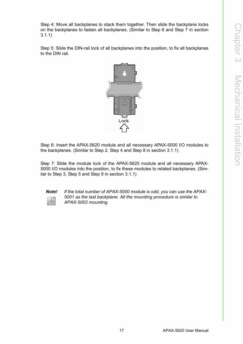
Step 4: Move all backplanes to stack them together. Then slide the backplane lockson the backplanes to fasten all backplanes. (Similar to Step 6 and Step 7 in section3.1.1)
Step 5: Slide the DIN-rail lock of all backplanes into the position, to fix all backplanesto the DIN rail.
Step 6: Insert the APAX-5620 module and all necessary APAX-5000 I/O modules tothe backplanes. (Similar to Step 2, Step 4 and Step 8 in section 3.1.1)
Step 7: Slide the module lock of the APAX-5620 module and all necessary APAX-5000 I/O modules into the position, to fix these modules to related backplanes. (Sim-ilar to Step 3, Step 5 and Step 9 in section 3.1.1)
Note! If the total number of APAX-5000 module is odd, you can use the APAX-5001 as the last backplane. All the mounting procedure is similar to APAX-5002 mounting.
17 APAX-5620 User Manual
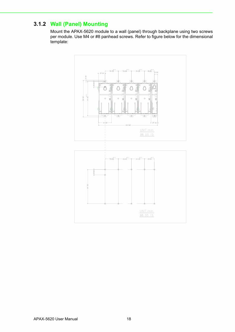
3.1.2 Wall (Panel) MountingMount the APAX-5620 module to a wall (panel) through backplane using two screwsper module. Use M4 or #8 panhead screws. Refer to figure below for the dimensionaltemplate:
APAX-5620 User Manual 18

Chapter 3
MechanicalInstallation
3.1.2.1 Wall (panel) mounting methodStep 1: Pull down the DIN-rail lock at the back of the first APAX-5002 backplane.
Step 2: Hang the APAX-5002 backplane onto the screw on the wall (panel). Thescrew for APAX-5002 to hang should be special-designed. We have provided it inaccessory.
19 APAX-5620 User Manual
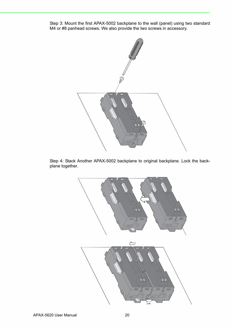
Step 3: Mount the first APAX-5002 backplane to the wall (panel) using two standardM4 or #8 panhead screws. We also provide the two screws in accessory.
Step 4: Stack Another APAX-5002 backplane to original backplane. Lock the back-plane together.
APAX-5620 User Manual 20

Chapter 3
MechanicalInstallation
Step 5: Mount that APAX-5002 backplane to the wall (panel) using two standard M4or #8 panhead screws.
Step 6: Repeat Step 4 ~ Step 5 until all necessary APAX-5002 backplane arescrewed on the wall (panel).
Note! When the total number of APAX-5620 and APAX-5000 I/O modules is odd, you can use APAX-5001 (1-slot backplane) as the last backplane in the system. The procedure to screw APAX-5001 on the wall (panel) is similar as APAX-5002.
21 APAX-5620 User Manual

Step 7: Insert APAX-5620 and all necessary APAX-5000 I/O modules to the back-planes. (Similar to Step 2, Step 4 and Step 8 in section 3.1.1)
Step 8: Lock APAX-5620 and all necessary APAX-5000 I/O module to the backplaneby pull down the buckle. (Similar to Step 3, Step 5 and Step 9 in section 3.1.1)
Warning! APAX-5620 will generate a significant heat, which is dissipated via a passive ventilation system. This system requires the unit to be mounted correctly. In order to have better ventilation, no matter DIN-rail or wall mounting is adopt, remember to locate APAX-5620 at the first slot on the first backplane. Besides, APAX-5620 and all APAX-5000 I/O mod-ules should be placed vertically. (Refer to figure below)
APAX-5620 User Manual 22

Chapter 3
MechanicalInstallation
We suggest remaining enough clearance space from enclosure walls and adjacentequipment. No closer than 50 mm (2 in.) apart on all sides, as shown below. This pro-vides ventilation and makes assembly easier.
23 APAX-5620 User Manual

APAX-5620 User Manual 24

Chapter 4
4 Error Handling and Diagnostics
4.1 Error Handling and DiagnosticsThere are four LED for diagnostics on the front panel of APAX-5620. Below are themeanings for the 4 LEDs:
PWR: When the APAX-5620 is powered, this LED will be lit (Green) RUN: Programmer can use software to define when this LED is lit. (Green) ERR: Programmer can use software to define when this LED is lit. (Orange) BAT: When the battery is out of power, this LED will be lit (Orange). Once this
LED is lit, you need to change the battery. Refer to Section 1.3.1 for how to change the battery.
Note! For APAX-5620KW, If you download KW program to it and select to run the program, the RUN LED will flash to notice the program is running.
APAX-5620 User Manual 26

Appendix A
A RS-485 Network
A.1 RS-485 Network EIA RS-485 is industry's most widely used bidirectional, balanced transmission linestandard. It is specifically developed for industrial multi-drop systems that should beable to transmit and receive data at high rates or over long distances.
The specifications of the EIA RS-485 protocol are as follows:
- Max line length per segment: 1200 meters (4000 feet)
- Throughput of 10 Mbaud and beyond
- Differential transmission (balanced lines) with high resistance against noise
- Maximum 32 nodes per segment
- Bi-directional master-slave communication over a single set of twisted pair cables
- Parallel connected nodes, true multi-drop
ADAM modules are fully isolated and use just a single set of twisted pair wires tosend and receive! Since the nodes are connected in parallel they can be freely dis-connected from the host without affecting the functioning of the remaining nodes. Inindustry shielded twisted pair is preferable due to the high noise ratio of the environ-ment.
When nodes communicate through the network, no sending conflicts can occur sincea simple command/response sequence is used. There is always one initiator (with noaddress) and many slaves (with address). In this case the master is a personal com-puter that is connected with its serial, RS-232, port to an ADAM RS-232/RS-485 con-verter. The slaves are the ADAM I/O modules. When modules are not transmittingdata, they are in listen mode. The host computer initiates a command/responsesequence with one of the modules. Commands normally contain the address of themodule the host wants to communicate with. The module with the matching addresscarries out the command and sends its response to the host.
A.2 Basic Network Layout Multi-drop RS-485 implies that there are two main wires in a segment. The con-nected modules tap from these two lines with so called drop cables. Thus all connec-tions are parallel and connecting or disconnecting of a node doesn't affect thenetwork as a whole. Since ADAM modules use the RS-485 standard, and use anASCII-based commands set, they can connect and communicate with all ASCII-based computers and terminals. The basic layouts that can be used for an RS-485network are:
Daisy Chain
The last module of a segment is a repeater. It is directly connected to the main-wiresthereby ending the first segment and starting the next segment. Up to 32 address-able modules can be daisy chained. This limitation is a physical one. When usingmore modules per segment the IC driver current rapidly decreases, causing commu-nication errors. Totally the network can hold up to 256 addressable modules. The lim-itation for this number is the two number hexadecimal address codes that know 256combinations. The ADAM converter, ADAM repeaters and the host computer are nonaddressable units and therefore are not included in these numbers.
APAX-5620 Manual 28

Appendix A
RS
-485N
etwork
Star Layout
In this scheme the repeaters are connected to drop-down cables from the main wiresof the first segment. A tree structure is the result. This scheme is not recommendedwhen using long lines since it will cause a serious amount of signal distortion due to asignal reflection in a several line endings.
Random
This is a combination of daisy chain and hierarchical structure.
29 APAX-5620 Manual

A.2.1 Line Termination Each discontinuity in impedance causes reflections and distortion. When an imped-ance discontinuity occurs in the transmission line the immediate effect is signalreflection. This will lead to signal distortion. Specially at line ends this mismatchcauses problems. To eliminate this discontinuity terminate the line with a resistor.
Figure A.1 Signal Distortion
The value of the resistor should be a close as possible to the characteristic imped-ance of the line. Although receiver devices add some resistance to the whole of thetransmission line, normally it is sufficient to the resistor impedance should equal thecharacteristic impedance of the line.
Example: Each input of the receivers has a nominal input impedance of 18 kW feed-ing into a diode transistor- resistor biasing network that is equivalent to an 18 kWinput resistor tied to a common mode voltage of 2.4 V. It is this configuration whichprovides the large common range of the receiver required for RS-485 systems.
Figure A.2 Termination Resistor Locations
APAX-5620 Manual 30

Appendix A
RS
-485N
etwork
Because each input is biased to 2.4 V, the nominal common mode voltage of bal-anced RS-485 systems, the 18 kW on the input can be taken as being in seriesacross the input of each individual receiver.
If thirty of these receivers are put closely together at the end of the transmission line,they will tend to react as thirty 36kW resistors in parallel with the termination resistor.The overall effective resistance will need to be close to the characteristics of the line.
The effective parallel receiver resistance RP will therefore be equal to:
RP = 36 x 103/30 = 1200 W
While the termination receptor RT will equal:
RT = RO / [1 - RO/RP]
Thus for a line with a characteristic impedance of 100 W resistor, the terminationresistor RT should be:
RT = 100/[1 - 100/1200] = 110 W
Since this value lies within 10% of the line characteristic impedance, thus as alreadystated above the line termination resistor RT will normally equal the characteristicimpedance ZO.
The star connection causes a multitude of these discontinuities since there are sev-eral transmission lines and is therefore not recommend.
Note! The recommended wiring method that causes a minimum amount of reflection is daisy chaining where all receivers tap from one transmis-sion line and needs to be terminated only twice.
31 APAX-5620 Manual

A.3 RS-485 Data Flow Control The RS-485 standard uses a single pair of wires to send and receive data. This linesharing requires some method to control the direction of the data flow. RTS (RequestTo Sent) and CTS (Clear To Sent) are the most commonly used method.
Figure A.3 RS-485 Data Flow Control with RTS
Intelligent RS-485 Control (auto data flow)
Devices with auto data flow feature are equipped with an I/O circuit which can auto-matically sense the direction of the data flow. No handshaking with the host (likeRTS, Request to Send) is necessary to receive data and forward it in the correctdirection. You can use any software written for half-duplex RS-232 with an ADAMnetwork without modification. The RS-485 control is completely transparent to theuser.
APAX-5620 Manual 32