Embed Size (px)
Citation preview

www.buffalotech.com
User Manual - AirStation WHR-HP-AG108
High Power Dual A + G Smart Wireless Router
v1.3

�
Table of Contents
Introduction . . . . . . . . . . . . . . . . . . . . . . . . . . . . . . . . . . . . . . . . . . . . . . . . . . . . 5Basic Setup . . . . . . . . . . . . . . . . . . . . . . . . . . . . . . . . . . . . . . . 6AOSS . . . . . . . . . . . . . . . . . . . . . . . . . . . . . . . . . . . . . . . . . . . . . . . . . 12Bridge/AP Mode . . . . . . . . . . . . . . . . . . . . . . . . . . . . . . . . . . . . . . 14AirStation Configuration Utility . . . . . . . . . . . . . . . . . . . . . . . . 17 Home . . . . . . . . . . . . . . . . . . . . . . . . . . . . . . . . . . . . . . . . 17 Port Mapping . . . . . . . . . . . . . . . . . . . . . . . . . . . 18 Firewall . . . . . . . . . . . . . . . . . . . . . . . . . . . 19 Windows (MSN) Messenger. . . . . . . . . . . . . . . . . . 20 Encryption . . . . . . . . . . . . . . . . . . . . . . . . . . . 21 Wireless Channel . . . . . . . . . . . . . . . . . . . . . . . . . . . 22 Firmware Update . . . . . . . . . . . . . . . . . . . . . . . . 23 Internet Connection Reset . . . . . . . . . . . . . . . . . . . . . 24
Advanced Tab . . . . . . . . . . . . . . . . . . . . . . . . . . . 25
WAN Configuration . . . . . . . . . . . . . . . . . . . . . . . . . . . . . 26
WAN port . . . . . . . . . . . . . . . . . . . . . . . . . . . . . 26
PPPoE. . . . . . . . . . . . . . . . . . . . . . . . . . . . . . . 27
LAN Configuration . . . . . . . . . . . . . . . . . . . . . . . . . . . . . . . . . 28
LAN Port . . . . . . . . . . . . . . . . . . . . . . . . 28
DHCP Server . . . . . . . . . . . . . . . . . . . . . 29

�
Table of Contents
Manual Assignment of IP Address . . . 30
Network Configuration. . . . . . . . . . . . . . . . . . . . . 31
Route information . . . . . . . . . . . . . . . . . . . . 31
Address Translation . . . . . . . . . . . . . . . . 33
IP Filter . . . . . . . . . . . . . . . . . . . . . . 35
Intrusion Detector . . . . . . . . . . . . . . . . . 38
UPnP . . . . . . . . . . . . . . . . . . . . . . . . . . . 39
Wireless Configuration . . . . . . . . . . . . . . . . . . . . . . . . 40
AOSS. . . . . . . . . . . . . . . . . . . . . . . . . 40
802.11a . . . . . . . . . . . . . . . . . . . . . . 41
Basic . . . . . . . . . . . . . . . . . . . . . . 41
Security . . . . . . . . . . . . . . . . . 42
802.11g . . . . . . . . . . . . . . . . . . . . . . 43
Basic . . . . . . . . . . . . . . . . . . . . . . 43
Security . . . . . . . . . . . . . . . . . 44
MAC access limit . . . . . . . . . . . . . . . . . . . . . . . . 45
Admin Configuration . . . . . . . . . . . . . . . . . . . 46
Password . . . . . . . . . . . . . . . . . . . 47
�
Table of Contents
Date/NTP . . . . . . . . . . . . . . . . . . . . . . . . . . . . 48
Syslog Transfer . . . . . . . . . . . . . . . . . . . . . . . . 49
Save/Load Configuration . . . . . . . . . . . . 50
Initialize/Reboot . . . . . . . . . . . . . . . . . . . . . . . . . . . 51 Firmware Update. . . . . . . . . . . . . . . . . . . . . . 52 Diagnostic. . . . . . . . . . . . . . . . . . . . . . . . . . . . . . . . . . . . . . . . 53 System Information. . . . . . . . . . . . . . . . . . . . . . 53 Log Info. . . . . . . . . . . . . . . . . . . . . . . . . . . 54 Packets Info. . . . . . . . . . . . . . . . . . . . . . . . . 55 Client Monitor. . . . . . . . . . . . . . . . . . . . . . 56 Ping Test. . . . . . . . . . . . . . . . . . . . . . 57Connecting to an existing network. . . . . . . . . . . . . . . . . . . . . . 58Antenna. . . . . . . . . . . . . . . . . . . . . . . . . . . . . . . . . . . . . . . 59
Specifications . . . . . . . . . . . . . . . . . . . . . . . . . . . . . . . . . . . 60Troubleshooting . . . . . . . . . . . . . . . . . . . . . . . . . . . . . 62Glossary . . . . . . . . . . . . . . . . . . . . . . . . . . . . . . . . . . . . . . . . . . . . . . . . . . . . 65FCC Information . . . . . . . . . . . . . . . . . . . . . . . . . . . . . . . . . . . . 72Warranty Information. . . . . . . . . . . . . . . . . . . . . 86Contact Information . . . . . . . . . . . . . . . . . . . . . . . . . . . . . . . . 87

�
Congratulations on your purchase! The AirStation High Power Combo A + G Wireless Router provides two separate wireless networks at the same time, one on the 2.4ghz 802.11g fre-quency and another on the 5ghz 802.11a frequency.
System Requirements• A high-speed (Broadband) Internet connection or existing local area connection.• A computer with a network connection (wired or wireless) and a good web browser. The
screenshots in this manual were taken with Firefox, but Netscape and Internet Explorer are also supported in versions 4.5 or later, and Safari 1.0 and later is supported with Macintosh OS X 10.2 and later.
AirStation WHR-HP-AG108 Package Contents• WHR-HP-AG108 Base Station• Antenna• AC adapter and power cable• CAT5 LAN cable • Utility CD with Manual• Quick Setup Guides• Warranty Statement
Introduction

�
Begin by finding a good place to set up your router/access point. Some things to consider:
• You’ll need to be able to plug your internet connection into it, so it should go within reach of the LAN cable from your DSL or Cable modem. You’ll also want a power outlet nearby.
• Keep the access point as central in your work area as possible. Signal strength and speed fall off with distance.
• Higher is often better. For instance, set it up on the top shelf of a bookcase rather than the bottom one, if possible.
Screw the antenna into the top of your AirStation. It will probably work best if you orient it to point straight up.
Basic Setup
�
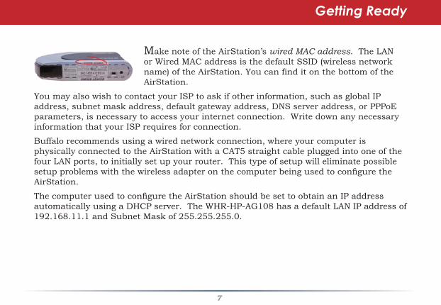
Make note of the AirStation’s wired MAC address. The LAN or Wired MAC address is the default SSID (wireless network name) of the AirStation. You can find it on the bottom of the AirStation.
You may also wish to contact your ISP to ask if other information, such as global IP address, subnet mask address, default gateway address, DNS server address, or PPPoE parameters, is necessary to access your internet connection. Write down any necessary information that your ISP requires for connection.
Buffalo recommends using a wired network connection, where your computer is physically connected to the AirStation with a CAT5 straight cable plugged into one of the four LAN ports, to initially set up your router. This type of setup will eliminate possible setup problems with the wireless adapter on the computer being used to configure the AirStation.
The computer used to configure the AirStation should be set to obtain an IP address automatically using a DHCP server. The WHR-HP-AG108 has a default LAN IP address of 192.168.11.1 and Subnet Mask of 255.255.255.0.
Getting Ready
�
1. Power down the Cable or DSL modem and the computer which will be used to configure the AirStation router.
2. Plug the Cable or DSL’s LAN Ethernet cable into the AirStation’s WAN port. Initially, you may need to unplug this cable from your computer, hub or other router.
3. Plug the provided Ethernet cable into a LAN port on the AirStation and plug the other end into your computer’s Ethernet adapter (NIC). If you plan to initially configure the AirStation wirelessly (not recommended), you may skip this step.
4. Power on your cable or DSL modem and wait one full minute, then power on the AirStation router and wait one full minute, and finally power on the computer which will be used to configure the AirStation. If the red DIAG light on the AirStation is lit or flashing after several minutes of being powered on, please consult Buffalo Technology Technical Support.
Connecting your AirStation
�
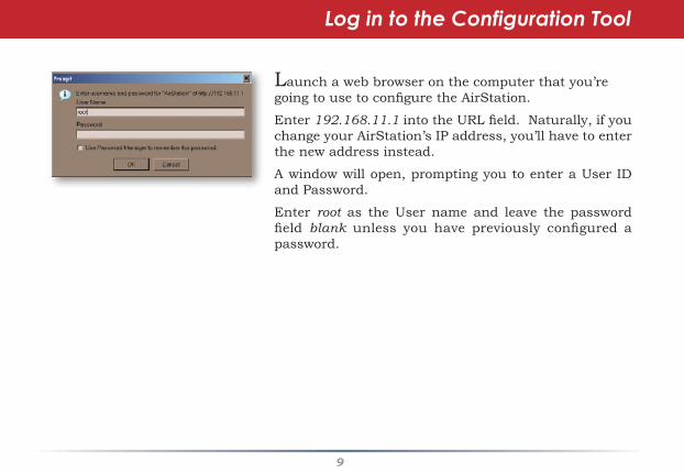
Launch a web browser on the computer that you’re going to use to configure the AirStation.
Enter 192.168.11.1 into the URL field. Naturally, if you change your AirStation’s IP address, you’ll have to enter the new address instead.
A window will open, prompting you to enter a User ID and Password.
Enter root as the User name and leave the password field blank unless you have previously configured a password.
Log in to the Configuration Tool
10
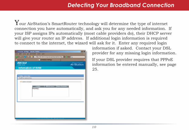
Your AirStation’s SmartRouter technology will determine the type of internet connection you have automatically, and ask you for any needed information. If your ISP assigns IPs automatically (most cable providers do), their DHCP server will give your router an IP address. If additional login information is required to connect to the internet, the wizard will ask for it. Enter any required login
Detecting Your Broadband Connection
information if asked. Contact your DSL provider for any missing login information.
If your DSL provider requires that PPPoE information be entered manually, see page 25.

11
This is the opening page of your AirStation’s configuration tool. You can always get to it from within the configuration screens by clicking on Home. From here, you can configure port mapping for your internet games, turn on UPnP for Windows (MSN) Messenger, configure your Firewall, setup Encryption, choose your Wireless channel, Enable IPv6, update your AirStation’s firmware, and reset your Internet connection’s configuration. As you explore the configuration tool, you
can usually get context sensitive help by clicking on the Help link at the top right of the page.
To go to Advanced Settings (page 25), click on the Advanced tab. To get the system information you need to set up a wireless client that doesn’t support AOSS, click on the System Info tab. See page 17 for more on Home.
Home
1�
AOSS
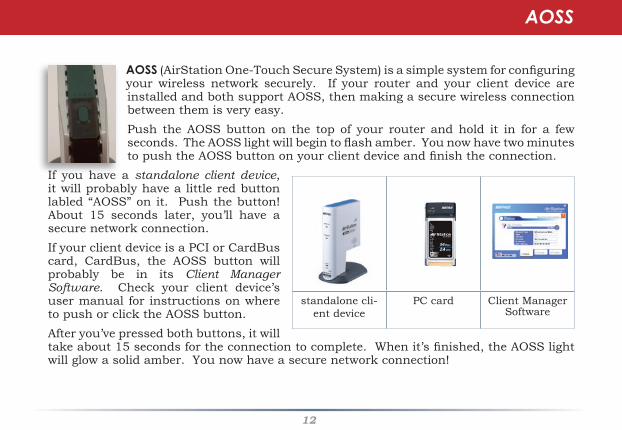
AOSS (AirStation One-Touch Secure System) is a simple system for configuring your wireless network securely. If your router and your client device are installed and both support AOSS, then making a secure wireless connection between them is very easy.Push the AOSS button on the top of your router and hold it in for a few seconds. The AOSS light will begin to flash amber. You now have two minutes to push the AOSS button on your client device and finish the connection.
If you have a standalone client device, it will probably have a little red button labled “AOSS” on it. Push the button! About 15 seconds later, you’ll have a secure network connection. If your client device is a PCI or CardBus card, CardBus, the AOSS button will probably be in its Client Manager Software. Check your client device’s user manual for instructions on where to push or click the AOSS button.After you’ve pressed both buttons, it will take about 15 seconds for the connection to complete. When it’s finished, the AOSS light will glow a solid amber. You now have a secure network connection!
standalone cli-ent device
PC card Client ManagerSoftware
AOSS
1�
Some things to keep in mind
• Only one AOSS wireless client adapter can be configured with the AOSS router at a time. The buttons will need to be re-pressed to connect each additional AOSS wireless client adapter.
• It is not necessary to AOSS client devices that have already been configured via AOSS, unless significant changes have been made to the wireless network.
• Do not attempt to configure two separate AOSS networks at the same time, as it may cause undesired configurations.
• If an undesired client has connected via AOSS, it can be disconnected from within the WHR-HP-AG108’s advanced configuration menus.
AOSS Notes
1�
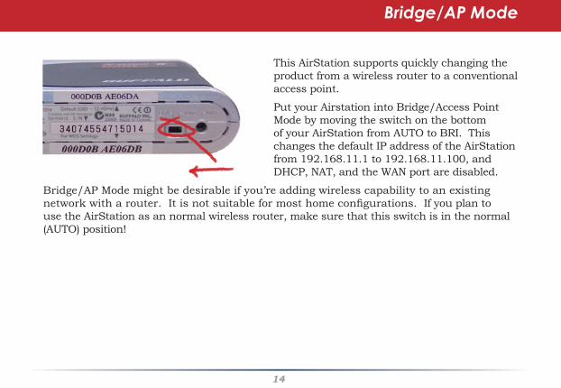
This AirStation supports quickly changing the product from a wireless router to a conventional access point.
Put your Airstation into Bridge/Access Point Mode by moving the switch on the bottom of your AirStation from AUTO to BRI. This changes the default IP address of the AirStation from 192.168.11.1 to 192.168.11.100, and DHCP, NAT, and the WAN port are disabled.
Bridge/AP Mode might be desirable if you’re adding wireless capability to an existing network with a router. It is not suitable for most home configurations. If you plan to use the AirStation as an normal wireless router, make sure that this switch is in the normal (AUTO) position!
Bridge/AP Mode
1�
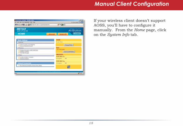
If your wireless client doesn’t support AOSS, you’ll have to configure it manually. From the Home page, click on the System Info tab.
Manual Client Configuration
1�
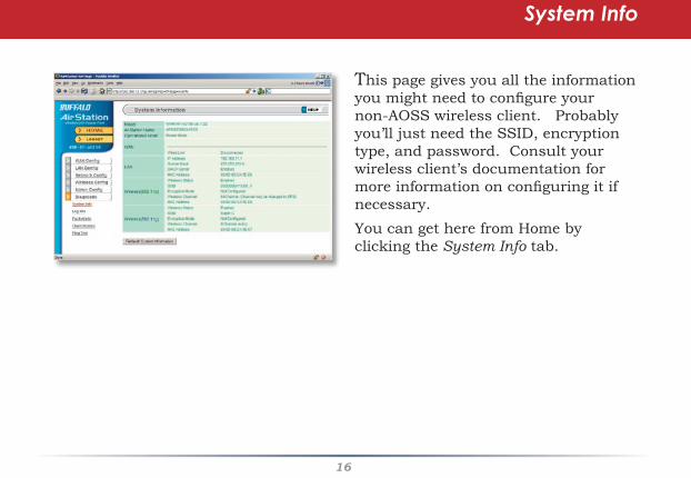
This page gives you all the information you might need to configure your non-AOSS wireless client. Probably you’ll just need the SSID, encryption type, and password. Consult your wireless client’s documentation for more information on configuring it if necessary.You can get here from Home by clicking the System Info tab.
System Info

1�
AirStation Configuration Tool (Home)
When you first open your AirStation Configuration Tool, it will take you to Home (see also page 11). From Home, you can configure port mapping for your internet games, set UPnP for Windows (MSN) Messenger, configure your firewall, setup encryption, choose your wireless channel, enable IPv6, update your AirStation’s firmware, and reset your Internet Connection’s configuration. Clicking the Advanced tab gives you access to all of the AirStation’s configuration tools.You can get back to Home from anywhere in the management tool by clicking on the Home button at the top left of the screen.Let’s begin exploring advanced settings by clicking on Internet Games (Port Mapping).

1�
Internet Games (Port Mapping)
Select any ports that need to be opened for your internet games to function correctly. Consult your game’s documentation for more information on what ports need to be configured.
1�
Firewall/Intrusion Detector
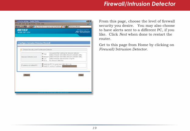
From this page, choose the level of firewall security you desire. You may also choose to have alerts sent to a different PC, if you like. Click Next when done to restart the router.
Get to this page from Home by clicking on Firewall/Intrusion Detector.
�0
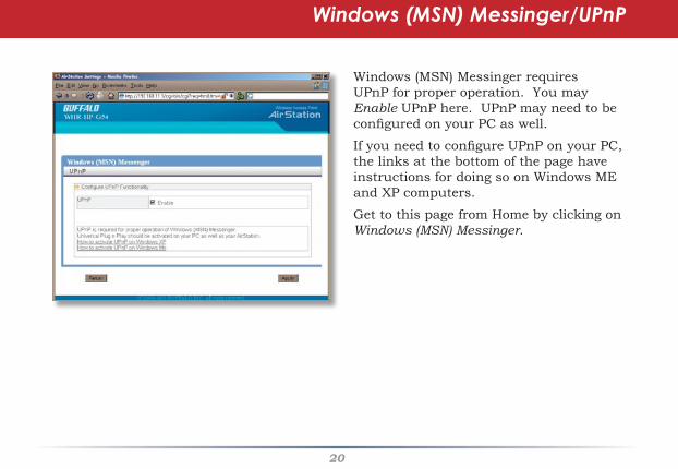
Windows (MSN) Messinger/UPnP
Windows (MSN) Messinger requires UPnP for proper operation. You may Enable UPnP here. UPnP may need to be configured on your PC as well.
If you need to configure UPnP on your PC, the links at the bottom of the page have instructions for doing so on Windows ME and XP computers.
Get to this page from Home by clicking on Windows (MSN) Messinger.

�1
Wireless Encryption
This page is available from Home by selecting Wireless Encryption. Here, you can manually select the type of wireless encryption you’d like to use. Please select the band you wish to configure, a, g, or both the same. Your AirStation supports three different encryption schemes; choose the best one that all your clients support.
Virtually all wireless clients support WEP. It’s a lot better than nothing.
TKIP is much more secure than WEP, but slower.
AES is even more secure than TKIP, and the fastest of all. Highly recommended if all of your wireless clients support it.
Note that TKIP and AES are forms of WPA, and may be referred to by that name in your wireless client’s documentation.

��
This page is available from Home by selecting Wireless channel. With Auto Channel selected, your AirStation will choose the best channel available. Auto Channel is available on both the a and g band and is the recommended setting if you are unaware of which channel will be optimal for your wireless network.This page also includes tips for avoiding channel interference.
Wireless Channel

��
This page is available from Home by selecting Firmware update. Use Browse to select your firmware update file, and then click on Apply. Firmware update may take several minutes to complete. Don’t power down your AirStation until the diag LED has gone out.
Firmware Update
��
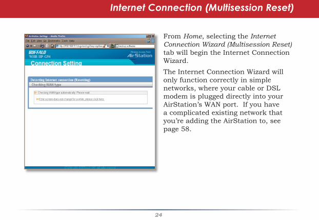
Internet Connection (Multisession Reset)
From Home, selecting the Internet Connection Wizard (Multisession Reset) tab will begin the Internet Connection Wizard.The Internet Connection Wizard will only function correctly in simple networks, where your cable or DSL modem is plugged directly into your AirStation’s WAN port. If you have a complicated existing network that you’re adding the AirStation to, see page 58.

��
Advanced Settings
Advanced Settings lets you configure every element of your AirStation. Get to Advanced Settings from Home by clicking the Advanced Tab. You may return to Home by clicking on the yellow > Home link in the top left corner.
Click Help in the top right corner for more information about any of the pages in Advanced Settings.To begin, click on WAN Config. The first page in WAN Config, WAN Port, will open.
��
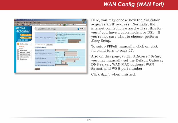
WAN Config (WAN Port)
Here, you may choose how the AirStation acquires an IP address. Normally, the internet connection wizard will set this for you if you have a cablemodem or DSL. If you’re not sure what to choose, perform Easy Setup.
To setup PPPoE manually, click on click here and turn to page 27.
Also on this page, under Advanced Setup, you may manually set the Default Gateway, DNS server, WAN MAC address, WAN format, and WEB port number.
Click Apply when finished.

��
PPPoE
Many DSL connections require a PPPoE Connection in order to log in to an internet connection. Normally, the Easy Detection Wizard will help you configure that, but you may manually configure one here. Consult your ISP for more information on correctly configuring your PPPoE connection.
To add a new PPPoE connection, click Edit Connection List. To choose your preferred connection, click on Edit Preferred Connection List.
��
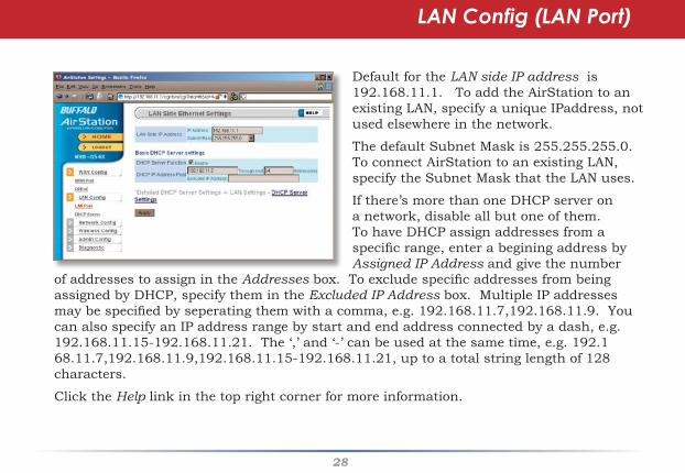
LAN Config (LAN Port)
Default for the LAN side IP address is 192.168.11.1. To add the AirStation to an existing LAN, specify a unique IPaddress, not used elsewhere in the network.
The default Subnet Mask is 255.255.255.0. To connect AirStation to an existing LAN, specify the Subnet Mask that the LAN uses.
If there’s more than one DHCP server on a network, disable all but one of them. To have DHCP assign addresses from a specific range, enter a begining address by Assigned IP Address and give the number
of addresses to assign in the Addresses box. To exclude specific addresses from being assigned by DHCP, specify them in the Excluded IP Address box. Multiple IP addresses may be specified by seperating them with a comma, e.g. 192.168.11.7,192.168.11.9. You can also specify an IP address range by start and end address connected by a dash, e.g. 192.168.11.15-192.168.11.21. The ‘,’ and ‘-’ can be used at the same time, e.g. 192.168.11.7,192.168.11.9,192.168.11.15-192.168.11.21, up to a total string length of 128 characters.
Click the Help link in the top right corner for more information.
��
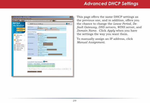
Advanced DHCP Settings
This page offers the same DHCP settings as the previous one, and in addition, offers you the chance to change the Lease Period, De-fault Gateway, DNS servers, WINS server, and Domain Name. Click Apply when you have the settings the way you want them.
To manually assign an IP address, click Manual Assignment.
�0
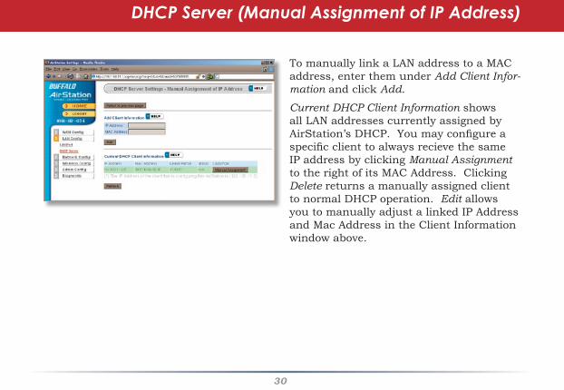
To manually link a LAN address to a MAC address, enter them under Add Client Infor-mation and click Add.
Current DHCP Client Information shows all LAN addresses currently assigned by AirStation’s DHCP. You may configure a specific client to always recieve the same IP address by clicking Manual Assignment to the right of its MAC Address. Clicking Delete returns a manually assigned client to normal DHCP operation. Edit allows you to manually adjust a linked IP Address and Mac Address in the Client Information window above.
DHCP Server (Manual Assignment of IP Address)

�1
By default, the AirStation receives RIP (Route Information Protocol) informa-tion only from your local network, and doesn’t broadcast RIP at all. For large, complicated network configurations, you may wish to modify this behavior. Click Apply when you have your desired configuration.
Lower on the page, routing information is displayed. Click Edit Routing Informa-tion to add a new route manually.
Network Config (Route Info)
��
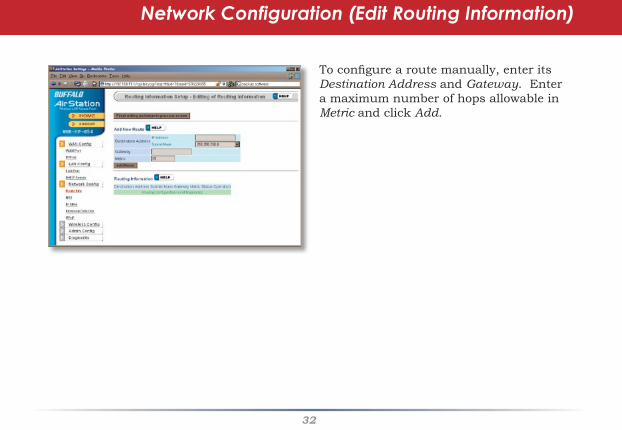
To configure a route manually, enter its Destination Address and Gateway. Enter a maximum number of hops allowable in Metric and click Add.
Network Configuration (Edit Routing Information)

��
NAT
You may disable Network Address Translation and IPsec passthrough by unchecking the appropriate Enable boxes. If you have a DMZ, enter its IP address in the IP Address of DMZ box. Incoming packets containing no recognizable destination port information will be redirected to the DMZ’s IP address.
IPv6 pass through can also be enabled here. This feature should only be enabled if instructed to do so by a network administrator or your ISP.
Click Apply when done.
To set a NAT table entry manually, click Edit NAT Table.
��
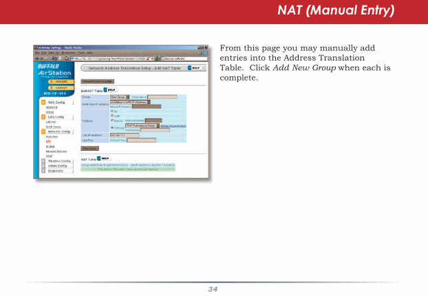
NAT (Manual Entry)
From this page you may manually add entries into the Address Translation Table. Click Add New Group when each is complete.

��
Your AirStation comes pre-configured with basic rules. You may choose which of these to use by clicking on Add/Delete Basic Rules and turning to page 36.
To make a custom rule, click on Configure IP Filter (page 37).
IP Filter

��
Get here by clicking on Add/Delete Basic Rules (see page 35). You may choose which of AirStation’s preconfigured basic rules are enabled or disabled. Active rules are displayed with a green background, and disabled rules are shown in red. Choose the rules you want to use by clicking under Operation. When your choices are complete, click on Initialize.
IP Filter (Add/Delete Basic Rules)

��
Clicking on Configure IP Filter from the IP filter page (page 35) will bring you to this page, where you can make your own rules. Click Add Rule when you have each rule configured the way you want it.
IP Filter (Configure IP Filter)

��
Network Configuration (Intrusion Detector)
To enable intrusion detector, choose Enable or Enable (Apply packet filter rules) from the Intrusion Detector drop-down box. If packet filter rules are applied, packets will be filtered with packet filter rules before Intrusion Detector is applied.
Blocking IP spoofing blocks packets from devices using an IP address that is not their own.
In the Threshold Value box, enter the number of times an event has to occur before you receive notification.
To configure your email alerts, enter your email address and mail server information. You may make up a sender email address,
such as “[email protected]”. Alert emails will appear to come from this address.
Intrusion detector also blocks unauthorized access attempts and suspicious traffic from WAN-side devices (the internet).
��
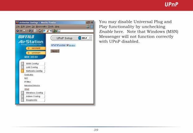
You may disable Universal Plug and Play functionality by unchecking Enable here. Note that Windows (MSN) Messenger will not function correctly with UPnP disabled.
UPnP
�0
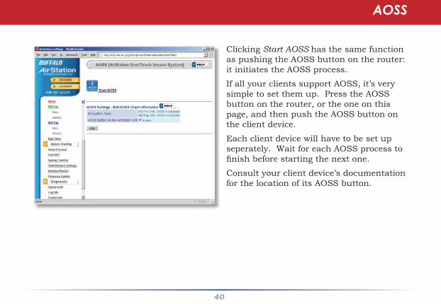
Clicking Start AOSS has the same function as pushing the AOSS button on the router: it initiates the AOSS process.
If all your clients support AOSS, it’s very simple to set them up. Press the AOSS button on the router, or the one on this page, and then push the AOSS button on the client device.
Each client device will have to be set up seperately. Wait for each AOSS process to finish before starting the next one.
Consult your client device’s documentation for the location of its AOSS button.
AOSS

�1
The SSID or network name can be changed by entering a custom SSID and pressing the Apply button.
Be careful changing the settings under “Advanced Settings”. It’s safe to experiment with different SuperAG settings, but don’t change the other advanced settings unless you have a reason to do so.
SuperAG technology uses channel bonding to maximize data throughput. The enhanced performance is only available to computer or wireless devices that have a
compatible SuperA or SuperG card, like the Buffalo High Power Dual A + G Wireless USB 2.0 Adapter. SuperAG mode allows wireless network speeds up to 108* Mbps. Use with compression is recommended to use SuperAG on A band. To use SuperAG on G band, see page 43.
802.11a (Basic)

��
Buffalo recommends that you choose the strongest form of encryption that’s supported by all your client devices.
• WEP is a lot better than nothing, and almost every wireless device ever made supports it.
• TKIP is slower than WEP but much more secure.
• AES is the most secure of all, and the quickest as well. Use it if you can.
Setting the key renewal period too short can decrease network performance.
802.11a (Security)
By default, the AirStation broadcasts its SSID. This makes it easier for clients to connect to the AirStation. To disable broadcasting, uncheck this box.
Privacy Seperator prevents wireless clients from being able to browse each other’s computers. Check Enable to turn it on.

��
If you have a mixed mode network, with both 802.11b and 802.11g clients, it’s recommended that you check 11g protection to ensure that slower 11b clients don’t hog all available bandwidth.
Choosing Auto for Wireless mode lets both 802.11b and 802.11g clients connect to the network. If you would prefer to allow only one or the other, you have those options as well.
Be careful changing settings under “Advanced Settings”. 802.11g Protection and SuperAG settings are safe to experiment with, but don’t change the other advanced settings unless you have a reason to do so.
SuperAG technology uses channel bonding to maximize data throughput. The enhanced performance is only available to computer or wireless devices that have a compatible SuperA or SuperG card, like the Buffalo High Power Dual A + G Wireless USB 2.0 Adapter. SuperAG mode allows wireless network speeds up to 108* Mbps. Use with compression is recommended to use SuperAG on G band.
802.11g (Basic)

��
Buffalo recommends that you choose the strongest form of encryption that’s supported by all your client devices.
• WEP is a lot better than nothing, and almost every wireless device ever made supports it.
• TKIP is slower than WEP but much more secure.
• AES is the most secure of all, and the quickest as well. Use it if you can.
Setting the key renewal period too short can decrease network performance.
802.11g (Security)
By default, the AirStation broadcasts its SSID. This makes it easier for clients to connect to the AirStation. To disable broadcasting, uncheck this box.
Privacy Seperator prevents wireless clients from being able to browse each other’s computers. Check Enable to turn it on.
��
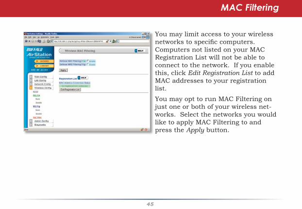
MAC Filtering
You may limit access to your wireless networks to specific computers. Computers not listed on your MAC Registration List will not be able to connect to the network. If you enable this, click Edit Registration List to add MAC addresses to your registration list.You may opt to run MAC Filtering on just one or both of your wireless net-works. Select the networks you would like to apply MAC Filtering to and press the Apply button.
��
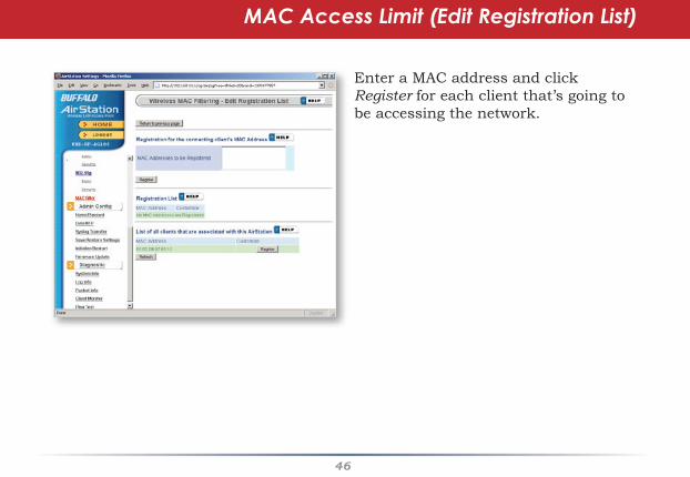
MAC Access Limit (Edit Registration List)
Advanced SettingsEnter a MAC address and click Register for each client that’s going to be accessing the network.

��
Here, you can change your AirStation’s name on your network and the administrator password. The name of the administrator account is fixed as “root”. If you have many AirStations on your network, having clear, descriptive names for each can make them much easier to administrate.
Admin Configuration (Name/Password)
��
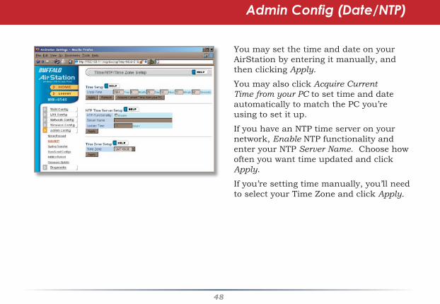
You may set the time and date on your AirStation by entering it manually, and then clicking Apply.
You may also click Acquire Current Time from your PC to set time and date automatically to match the PC you’re using to set it up.
If you have an NTP time server on your network, Enable NTP functionality and enter your NTP Server Name. Choose how often you want time updated and click Apply.
If you’re setting time manually, you’ll need to select your Time Zone and click Apply.
Admin Config (Date/NTP)
��
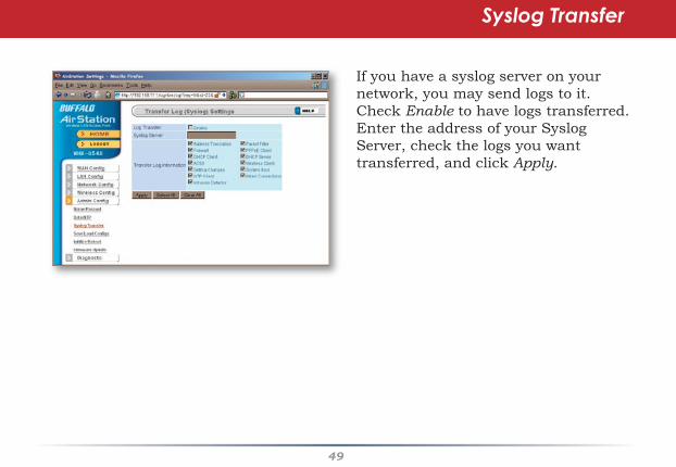
If you have a syslog server on your network, you may send logs to it. Check Enable to have logs transferred. Enter the address of your Syslog Server, check the logs you want transferred, and click Apply.
Syslog Transfer
�0
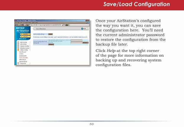
Once your AirStation’s configured the way you want it, you can save the configuration here. You’ll need the current administrator password to restore the configuration from the backup file later.Click Help at the top right corner of the page for more information on backing up and recovering system configuration files.
Save/Load Configuration
�1
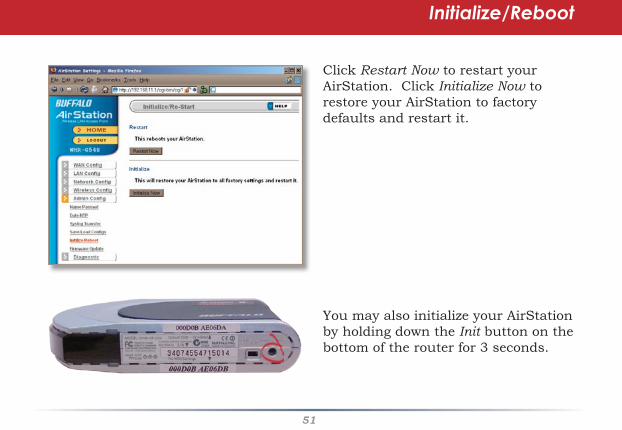
Click Restart Now to restart your AirStation. Click Initialize Now to restore your AirStation to factory defaults and restart it.
You may also initialize your AirStation by holding down the Init button on the bottom of the router for 3 seconds.
Initialize/Reboot

��
Click Browse to select your firmware update file. Then, click the Firmware Update button to update firmware.
Firmware Update may take several minutes to complete. Do not power down the router until Firmware Update is finished and the diag light on the front of the router has stopped blinking.
When available, updated firmware may be downloaded from www.buffalotech.com.
Firmware Update

��
The System Information page lists all the setup information for your AirStation. It can be very handy for setting up clients that don’t support AOSS.
System Information
��
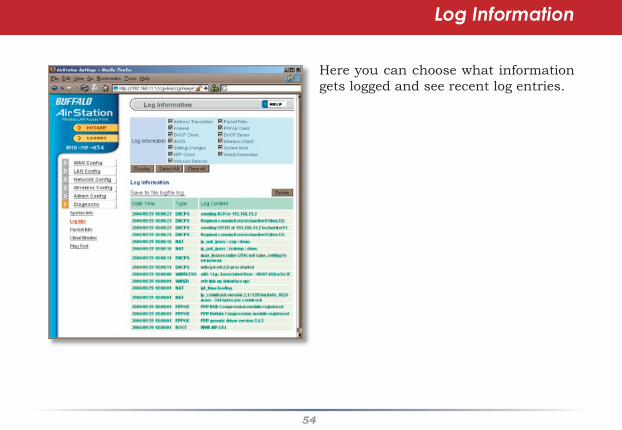
Here you can choose what information gets logged and see recent log entries.
Log Information
��
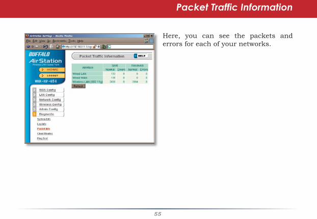
Here, you can see the packets and errors for each of your networks.
Packet Traffic Information

��
Client Monitor shows you a list of all clients currently connected to the wireless network.
Client Monitor
��
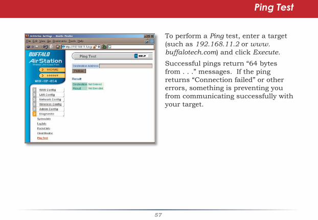
To perform a Ping test, enter a target (such as 192.168.11.2 or www.buffalotech.com) and click Execute.
Successful pings return “64 bytes from . . .” messages. If the ping returns “Connection failed” or other errors, something is preventing you from communicating successfully with your target.
Ping Test
��
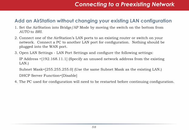
Connecting to a Preexisting Network
Add an AirStation without changing your existing LAN configuration1. Set the AirStation into Bridge/AP Mode by moving the switch on the bottom from
AUTO to BRI.
2. Connect one of the AirStation’s LAN ports to an existing router or switch on your network. Connect a PC to another LAN port for configuration. Nothing should be plugged into the WAN port.
3. Open LAN Settings - LAN Port Settings and configure the following settings:
IP Address =[192.168.11.1] (Specify an unused network address from the existing LAN.)
Subnet Mask=[255.255.255.0] (Use the same Subnet Mask as the existing LAN.)
DHCP Server Function=[Disable]
4. The PC used for configuration will need to be restarted before continuing configuration.

��
The WHR-HP-AG108’s external antenna will usually give the best performance if oriented to point straight up. If your AirStation is resting on its side, use the antenna’s swivel and twist function to orient it pointed upward.
Antenna
�0
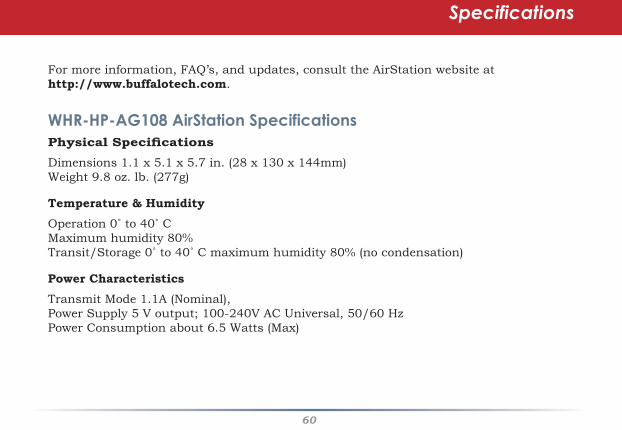
For more information, FAQ’s, and updates, consult the AirStation website at http://www.buffalotech.com.
WHR-HP-AG108 AirStation SpecificationsPhysical Specifications Dimensions 1.1 x 5.1 x 5.7 in. (28 x 130 x 144mm)Weight 9.8 oz. lb. (277g)
Temperature & Humidity Operation 0˚ to 40˚ C Maximum humidity 80%Transit/Storage 0˚ to 40˚ C maximum humidity 80% (no condensation)
Power CharacteristicsTransmit Mode 1.1A (Nominal), Power Supply 5 V output; 100-240V AC Universal, 50/60 HzPower Consumption about 6.5 Watts (Max)
Specifications
�1
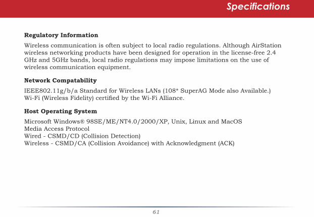
Regulatory InformationWireless communication is often subject to local radio regulations. Although AirStation wireless networking products have been designed for operation in the license-free 2.4 GHz and 5GHz bands, local radio regulations may impose limitations on the use of wireless communication equipment.
Network CompatabilityIEEE802.11g/b/a Standard for Wireless LANs (108* SuperAG Mode also Available.) Wi-Fi (Wireless Fidelity) certified by the Wi-Fi Alliance.
Host Operating SystemMicrosoft Windows® 98SE/ME/NT4.0/2000/XP, Unix, Linux and MacOSMedia Access ProtocolWired - CSMD/CD (Collision Detection) Wireless - CSMD/CA (Collision Avoidance) with Acknowledgment (ACK)
Specifications
��
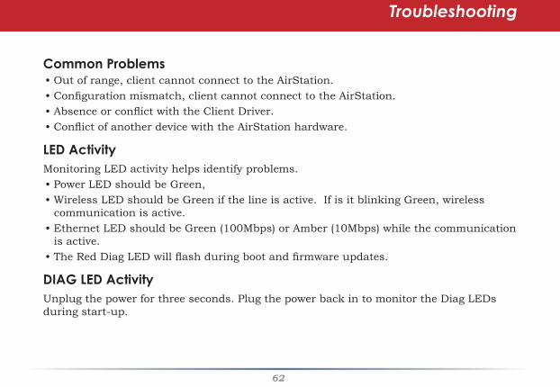
Common Problems• Out of range, client cannot connect to the AirStation.• Configuration mismatch, client cannot connect to the AirStation.• Absence or conflict with the Client Driver.• Conflict of another device with the AirStation hardware.
LED ActivityMonitoring LED activity helps identify problems. • Power LED should be Green,• Wireless LED should be Green if the line is active. If is it blinking Green, wireless
communication is active.• Ethernet LED should be Green (100Mbps) or Amber (10Mbps) while the communication
is active. • The Red Diag LED will flash during boot and firmware updates.
DIAG LED ActivityUnplug the power for three seconds. Plug the power back in to monitor the Diag LEDs during start-up.
Troubleshooting
��
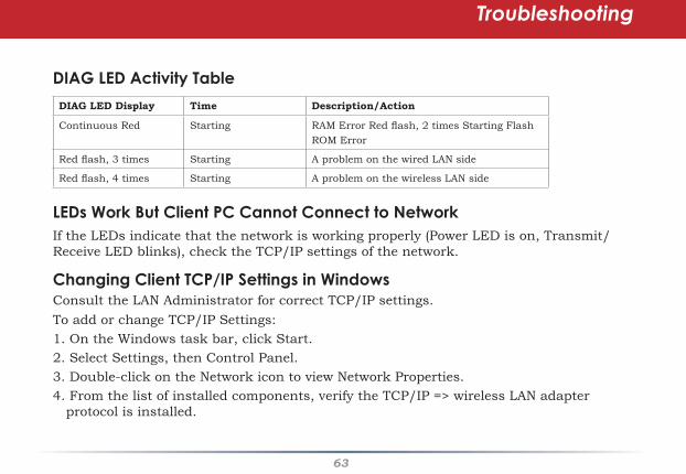
DIAG LED Activity Table
DIAG LED Display Time Description/Action
Continuous Red Starting RAM Error Red flash, 2 times Starting Flash ROM Error
Red flash, 3 times Starting A problem on the wired LAN side
Red flash, 4 times Starting A problem on the wireless LAN side
LEDs Work But Client PC Cannot Connect to Network If the LEDs indicate that the network is working properly (Power LED is on, Transmit/Receive LED blinks), check the TCP/IP settings of the network.
Changing Client TCP/IP Settings in WindowsConsult the LAN Administrator for correct TCP/IP settings. To add or change TCP/IP Settings:1. On the Windows task bar, click Start.2. Select Settings, then Control Panel.3. Double-click on the Network icon to view Network Properties.4. From the list of installed components, verify the TCP/IP => wireless LAN adapter
protocol is installed.
Troubleshooting

��
• If the wireless adapter protocol is not yet installed, click the Add button and select the TCP/IP protocol from the list. Refer to Windows Help for more information.
• If the wireless adapter protocol is installed, select the protocol and click the Properties button. Verify that the parameters match the settings provided by your LAN Administrator. Make changes if necessary, and click OK.
5. If prompted, restart your computer.
Other ProblemsPlease refer to www.buffalotech.com for further reference materials.
Troubleshooting
��
10BaseT: 802.3 based Ethernet network that uses UTP (Unshielded twisted pair) cable and a star topology. 10 Mbps data tansmission speed.
100BaseT: 802.3 based Ethernet network that uses UTP (Unshielded twisted pair) cable and a star topology. 100 Mbps data tansmission speed.
1000BaseT: 802.3 based Ethernet network that uses UTP (Unshielded twisted pair) cable and a star topology. 1000 Mbps data tansmission speed.
802.1x: The standard for wireless LAN authentication used between an AP and a client. 802.1x with EAP will initiate key handling.
Access Point: A hardware device that acts as a communication hub for Clients (users of wireless devices) to connect to a wired LAN.
Ad-Hoc Network: A network based on peer-to-peer communication rather than a router, switch, or hub.
Bandwidth: The transmission capacity of a computer or a communication channel, usually stated in Megabits per second (Mbps).
Bridge: A device which forwards traffic between network segments with a common network layer address, based on data link layer information.
Client: A PC, workstation, or other device that connects to a network wirelessly through an Access Point.
Cross-Over Cable: A UTP cable that has its transmit and receive pair crossed to allow communications between two devices.
Default Gateway: The IP Address of either the nearest router or server for the LAN.
Glossary
��
Destination Address: The address portion of a packet that identifies the intended recipient station.
DHCP (Dynamic Host Configuration Protocol): Based on BOOTP, it uses a pool of IP addresses, which it assigns to each device connected to it, and retrieves the address when the device becomes dormant for a period of time.
DNS (Domain Name System): System used to map readable machine names into IP addresses.
Driver: Software that interfaces a computer with a specific hardware device.
Dynamic IP Address: An IP address that is automatically assigned to a client station in a TCP/IP network, typically by a DHCP server.
Ethernet: The most widely used architecture for Local Area Networks (LANs). It is a shared-media network architecture. The IEEE 802.3 standard details its functionality.
Ethernet cable: A wire similar to telephone cable that carries signals between Ethernet devices. It is designed to connect a single device’s NIC to a router, switch, or hub. See also Crossover cable.
File and Print Sharing: A Microsoft application that allows computers on a network to share files and printers.
Firmware: Computer programming instructions that are stored in a read-only memory unit rather than being implemented through software.
Frame: A fixed block of data, transmitted as a single entity. Also referred to as a packet.
Glossary
��
Full-Duplex: To transmit on the same channel in both directions simultaneously.
Half-duplex: To transmit on the same channel in both directions, one direction at a time.
Hub: A device which allows connection of computers and other devices to form a LAN.
IEEE (Institute of Electrical and Electronics Engineers): The professional organization which promotes development of electronics technology.
IP (Internet Protocol) Address: A unique 32-binary-digit number that identifies each sender or receiver of information sent in packets.
Infrastructure: A wireless network or other small network in which the wireless network devices are made a part of the network through the Access Point.
ISP (Internet Service Provider): A company that provides access to the Internet and other related services.
IV (Initialization Vector): The header section of an encrypted message packet.
LAN (Local Area Network): A group of computers and peripheral devices connected to share resources.
LED (Light Emitting Diode): The lights on a hardware device representing the activity through the ports.
MAC (Medium Access Control) Address: The unique number that distinguishes every network interface card.
Mbps (Mega Bits Per Second): A measurement of millions of bits per second.
MDI/X (Media Dependent Interface/Cross-over): Port on a network hub or switch that crosses the incoming transmit lines with the outgoing receive lines.
Glossary

��
PCMCIA (Personal Computer Memory Card International Association) Card: Removable module that adds features to a portable computer.
Peer-to-peer: This simple network is formed by connecting computers directly, without use of routers or hubs. A crossover cable is plugged into an Ethernet port in each computer, connecting them directly.
Ping (Packet Internet Groper): An Internet utility used to determine whether a particular IP address is accessable.
Plug and Play: Hardware that, once physically installed, finishes its installation automatically and may immediately be used, as opposed to hardware that requires further manual configuration.
PoE (Power over Ethernet): A mechanism to send DC power to a device using a CAT5 Ethernet cable.
MHz (MegaHertz): One million cycles per second.
NAT (Network Address Translation): An internet standard that enables a LAN to use one set of IP addresses for internal traffic and a second set for external traffic.
NIC (Network Interface Card): An expansion card connected to a computer so the computer can be connected to a network.
Packet: A block of data that is transferred as a single unit, also called a frame or a block.
Packet Filtering: Discarding unwanted network traffic based on its originating address or its type.
PCI (Peripheral Component Interconnect): A bus that is connected directly to the CPU.
Glossary

��
PPPoE (Point-to-Point Protocol over Ethernet): A specification for connecting users on an Ethernet line to the Internet through a common broadband medium.
Protocol: A standard way of exchanging information between computers.
RADIUS (Remote Authentication Dial In User Service): A server that issues authentication keys to clients.
RAM (Random Access Memory): Non-permanent memory.
Repeater Hub: A device that collects, strengthens and transmits information to all connected devices, allowing the network to be extended to accommodate additional workstations. See also Bridge.
RC4: The encryption algorithm used by WEP.
RJ-45 connector: An 8-pin connector used between a twisted pair cable and a data transmission device.
ROM (Read Only Memory): Memory hardware that allows fast access to permanently stored data but prevents addition to or modification of the data.
Router: A device in a network that handles message transfer between computers. Similar to a hub, but with added functionality and efficiency.
Roaming: The ability to use a wireless device while moving from one access point to another without losing the connection.
Server: Any computer that makes files or peripheral devices available to users of the network and has a resident Network OS.
SMTP (Simple Mail Transfer Protocol): The protocol used to define and deliver electronic mail (E-mail) from one location to another.
Glossary
�0
SNMP (Simple Network Management Protocol: An application layer protocol that outlines the formal structure for communication among network devices.
Static IP Address: A permanent IP address is assigned to a node in a TCP/IP network. Also known as global IP.
STP (Shielded Twisted Pair): Twisted Pair cable wrapped in a metal sheath to provide extra protection from external interfering signals.
Subnet Mask: An eight-byte address divided into 4 parts separated by periods.
TCP/IP (Transmission Control Protocol/Internet Protocol: Protocol used by computers when communicating across the Internet or Intranet.
TKIP (Temporal Key Integrity Protocol): An encryption method replacing WEP. TKIP uses random IV and frequent key exchanges.
Topology: The shape of a LAN (Local Area Network) or other communications system.
Twisted Pair: Cable that comprises 2 or more pair of insulated wires twisted together.
UDP (User Datagram Protocol): A communication method (protocol) that offers a limited amount of service when messages are exchanged between computers in a network. UDP is used as an alternative to TCP/IP.
Uplink: Link to the next level up in a communication hierarchy.
UTP (Unshielded Twisted Pair) cable: Two or more unshielded wires twisted together to form a cable.
WAN (Wide Area Network): A networking system covering a wide geographical area.
Glossary
�1
WEP (Wired Equivalent Privacy): A security protocol for wireless local area networks defined in the 802.11b standard, using a 64 bit or 128 bit key. WEP was designed to provide the same level of security as that of a wired LAN. However, it has been found that WEP is not as secure as once believed.
Web Browser: A software program that allows viewing of web pages.
Wi-Fi (Wireless Fidelity): An organization that tests and assures interoperability among WLAN devices.
Wire Speed: The maximum speed at which a given packet can be transferred using Ethernet and Fast Ethernet standard specifications.
WLAN (Wireless LAN): A LAN topology using wireless devices.
VPN (Virtual Private Network): A security method to connect remote LAN users to a corporate LAN system.
Glossary

��
NoticeThis equipment has been tested and found to comply with the limits for a Class B digital device, pursuant to part 15 of the FCC Rules. These limits are designed to provide reasonable protection against harmful interference in a residential installation.This equipment generates, uses and can radiate radio frequency energy and, if not installed and used in accordance with the instructions, may cause harmful interference to radio communications. However, there is no guarantee that interference will not occur in a particular installation. If this equipment does cause harmful interference to radio or television reception, which can be determined by turning the equipment off and on, the user is encouraged to try to correct the interference by one or more of the following measures:•Reorient or relocate the receiving antenna.•Increase the separation between the equipment and receiver.•Connect the equipment into an outlet on a circuit different from that to which the receiver is connected.
•Consult the dealer or an experienced radio/TV technician for help.This device complies with Part 15 of the FCC Rules. Operation is subject to the following two conditions: (1) this device may not cause harmful interference, and (2) this device must accept any interference received, including interference that may cause undesired operation. In accordance with FCC regulation, BUFFALO has limited the WHR-HP-AG108 to operation on channels 1-11 by USA specific firmware.FCC Warning Changes or modifications not expressly approved by the party responsible for compliance could void the user’s authority to operate the equipment.
FCC RF Radiation Exposure StatementThis equipment complies with FCC radiation exposure limits set forth for uncontrolled
FCC / CE Information
��
equipment and meets the FCC radio frequency (RF) Exposure Guidelines in Supplement C to OET65. This equipment should be installed and operated with at least 20cm and more between the radiator and person’s body (excluding extremities: hands, wrists, feet and legs). This transmitter must not be co-located or operating in conjunction with any other antenna or transmitter.
SafetyThis equipment is designed with the utmost care for the safety of those who install and use it. However, special attention must be paid to the dangers of electric shock and static electricity when working with electrical equipment. All guidelines of this manual and of the computer manufacturer must therefore be allowed at all times to ensure the safe use of the equipment.EU Countries intended for useThe ETSI version of this device is intended for home and office use in Austria, Belgium, Denmark, Finland, France (with Frequency channel restrictions), Germany, Greece, Iceland, Ireland, Italy, Luxembourg, Norway, The Netherlands, Portugal, Spain, Sweden, Switzerland and United Kingdom. The ETSI version of this device is also authorized for use in EFTA member states Iceland, Liechtenstein, Norway and Switzerland.
EU Countries not intended for use
None.
Potential restrictive useFrance: Only channels 10,11,12, and 13.
FCC / CE Information
��
Federal Communication Commission Declaration of Conformity ( DoC ) StatementModel No: WHR-HP-AG108AirStation High Power Dual A+G SmartRouter
Buffalo Inc. 15, Shibata Hondori 4-chromeMinami-ku, Nagoya 457-8520Japan01181-52-241-7980
This equipment has been tested and found to comply with the limits for a Class B digitaldevice, pursuant to Part 15 of the FCC rules. These limits are designed to provide reasonableprotection against harmful interference in a residential installation. This equipment generates,uses, and can radiate radio frequency energy and, if not installed and used in accordance withthe instructions, may cause harmful interference to radio communications. However, there isno guarantee that interference will not occur in a particular installation. If this equipmentdoes cause harmful interference to radio or television reception, which can be determined byturning the equipment off and on, the user is encouraged to try to correct the interference by
��
one or more of the following measures:• Reorient or relocate the receiving antenna.• Increase the separation between the equipment and receiver.• Connect the equipment into an outlet on a circuit different from that to which the receiveris connected. • Consult the dealer or an experienced radio/TV technician for help.This device complies with Part 15 of the FCC Rules. Operation is subject to the followingtwo conditions: (1) This device may not cause harmful interference, and (2) This devicemust accept any interference received, including interference that may cause undesiredoperation.Caution:Any changes or modifications not expressly approved by the party responsible for productcompliance could void the user’s authority to operate the equipment.Within the 5.15-to-5.25-GHz band, UNII devices are restricted to indoor operations to reduceany potential for harmful interference to co-channel Mobile Satellite Systems (MSS) operationsCaution: Exposure to radio frequency radiation ( below is for mobile device )To comply with FCC RF exposure compliance requirements, a separation distance of at least20 cm must be maintained between the antenna of this device and all persons. This devicemust not be co-located or operating in conjunction with any other antenna or transmitter.

��
Caution Exposure to radio frequency radiation (below is for portable device)To comply with FCC RF exposure compliance requirements, this device must not be colocatedor operating in conjunction with any other antenna or transmitter.b. Industry Canada PortionCanada Regulatory Compliance StatementThis Class B digital apparatus complies with Canadian ICES-003.Cet appareil numériqué de la classe B est conformé à la norme NMB-003 duCanada.For Customers in CanadaThis device complies with RSS 210 of Industry Canada (IC).Operation is subject to the following two conditions:(1) this device may not cause interference, and(2) this device must accept any interference, including interference that may cause undesiredoperation of this device.L’ utilisation de ce dispositif est autorisée seulement aux conditions suivantes :(1) il ne doit pas produire de brouillage et(2) l’ utilisateur du dispositif doit étre prêt à accepter tout brouillage radioélectrique reçu,même si ce brouillage est susceptible de compromettre le fonctionnement du dispositif.
��
Caution: Within the 5.15-to-5.25-GHz band, UNII devices are restricted to indoor operations to reduce any potential for harmful interference to co-channel Mobile Satellite Systems (MSS) operations
Exposure to radio frequency radiation (below statement applied to mobile or portable device)The installer of this radio equipment must ensure that the antenna is located or pointed suchthat it does not emit RF field in excess of Health Canada limits for the general population;consult Safety Code 6, obtainable from Health Canada’s website at www.hc-sc.gc.ca/rpb.
c. EU PortionEuropean Community Declaration of Conformity with Regard to the R&TTE Directive1999/5/ECThe following standards were applied: (Omni)• Radio: EN 300-328 v1.6.1 (2.4-GHz operation)• EN 301-893 v1.2.3 (5-GHz operation)• EMC: EN 301.489-1 v1.4.1, EN 301.489-17 v1.2.1• Safety: IEC 60950 ( 1999 3rd Edition with Amend. 1,2,3,4 ) & EN 60950 ( 2000 )The following CE mark is affixed to the device:
��
Note: This equipment is intended to be used in all EU and EFTA countries. Outdoor use maybe restricted to certain frequencies and/or may require a license for operation. For moredetails, contact your customer service representative.To comply with RF exposure compliance requirements, a separation distance of at least 20cm must be maintained between the antenna of this device and all persons. This device mustnot be co-located or operating in conjunction with any other antenna or transmitter.Member States shall ensure that the manufacturer or the person responsible for placing theapparatus on the market provides information for the user on the intended use of theapparatus, together with the declaration of conformity to the essential requirements. Where itconcerns radio equipment, such information shall be sufficient to identify on the packagingand the instructions for use of the apparatus the Member States or the geographical areawithin a Member State where the equipment is intended to be used and shall alert the user bythe marking on the apparatus referred to in Annex VII, paragraph 5, to potential restrictionsor requirements for authorization of use of the radio equipment in certain Member States.

��
Declaration of Conformity with Regard to the R&TTE Directive 1999/5/ECČesky[Czech]Buffalo Technology Inc. tímto prohlašuje, že tento AirStation WHR-HP-AG108 je ve shodě se základními
požadavky a dalšími příslušnými ustanoveními směrnice 1999/5/ES.Dansk[Danish]Undertegnede Buffalo Technology Inc. erklærer herved, at følgende udstyr AirStation WHR-HP-AG108
overholder de væsentlige krav og øvrige relevante krav i direktiv 1999/5/EF.Deutsch[German]Hiermit erklärt Buffalo Technology Inc. dass sich das Gerät AirStation WHR-HP-AG108 in
Übereinstimmung mit den grundlegenden Anforderungen und den übrigen einschlägigen Bestimmungen der Richtlinie
1999/5/EG befindet.Eesti[Estonian]Käesolevaga kinnitab Buffalo Technology Inc. seadme AirStation WHR-HP-AG108 vastavust direktiivi
1999/5/EÜ põhinõuetele ja nimetatud direktiivist tulenevatele teistele asjakohastele sätetele.English Hereby, Buffalo Technology Inc. declares that this AirStation WHR-HP-AG108 is in compliance

�0
with the essential requirements and other relevant provisions of Directive 1999/5/EC.Español[Spanish]Por medio de la presente Buffalo Technology Inc. declara que el AirStation WHR-HP-AG108 cumple con
los requisitos esenciales y cualesquiera otras disposiciones aplicables o exigibles de la Directiva1999/5/CE.Ελληνική[Greek]ΜΕ ΤΗΝ ΠΑΡΟΥΣΑ Buffalo Technology Inc. ΔΗΛΩΝΕΙ ΟΤΙ AirStation WHR-HP-AG108
ΣΥΜΜΟΡΦΩΝΕΤΑΙ ΠΡΟΣ ΤΙΣ ΟΥΣΙΩΔΕΙΣ ΑΠΑΙΤΗΣΕΙΣ ΚΑΙ ΤΙΣ ΛΟΙΠΕΣ ΣΧΕΤΙΚΕΣ ΔΙΑΤΑΞΕΙΣ ΤΗΣ ΟΔΗΓΙΑΣ 1999/5/ΕΚ.
Français[French]Par la présente Buffalo Technology Inc. déclare que l’appareil AirStation WHR-HP-AG108 est conforme
aux exigences essentielles et aux autres dispositions pertinentes de la directive 1999/5/CE.Italiano[Italian]Con la presente Buffalo Technology Inc. dichiara che questo AirStation WHR-HP-AG108 è conforme
ai requisiti essenziali ed alle altre disposizioni pertinenti stabilite dalla direttiva 1999/5/CE.

�1
Latviski[Latvian]Ar šo Buffalo Technology Inc. deklarē, ka AirStation WHR-HP-AG108 atbilst Direktīvas 1999/5/EK
būtiskajām prasībām un citiem ar to saistītajiem noteikumiem.Lietuvių[Lithuanian]Šiuo Buffalo Technology Inc. deklaruoja, kad šis AirStation WHR-HP-AG108 atitinka esminius
reikalavimus ir kitas1999/5/EB Direktyvos nuostatas.Nederlands[Dutch]Hierbij verklaart Buffalo Technology Inc. dat het toestel AirStation WHR-HP-AG108 in overeenstemming
is met de essentiële eisen en de andere relevante bepalingen van richtlijn 1999/5/EG.Malti[Maltese]Hawnhekk, Buffalo Technology Inc. , jiddikjara li dan AirStation WHR-HP-AG108 jikkonforma mal-
ħtiġijiet essenzjali u ma provvedimenti oħrajn relevanti li hemm fid-Dirrettiva 1999/5/EC.Magyar[Hungarian]Alulírott, Buffalo Technology Inc. nyilatkozom, hogy a AirStation WHR-HP-AG108 megfelel a vonatkozó

��
alapvetõ követelményeknek és az 1999/5/EC irányelv egyéb elõírásainak.Polski[Polish]Niniejszym, Buffalo Technology Inc. , deklaruję, że AirStation WHR-HP-AG108 spełnia wymagania
zasadnicze oraz stosowne postanowienia zawarte Dyrektywie 1999/5/EC.Português[Portuguese]Buffalo Technology Inc. declara que este AirStation WHR-HP-AG108 está conforme com os requisitos
essenciais e outras disposições da Directiva 1999/5/CE.Slovensko[Slovenian]Buffalo Technology Inc. izjavlja, da je ta AirStation WHR-HP-AG108 v skladu z bistvenimi zahtevami
in ostalimi relevantnimi določili direktive 1999/5/ES.Slovensky[Slovak]Buffalo Technology Inc. týmto vyhlasuje, že AirStation WHR-HP-AG108 spĺňa základné požiadavky
a všetky príslušné ustanovenia Smernice 1999/5/ES.Suomi[Finnish]Buffalo Technology Inc. vakuuttaa täten että AirStation WHR-HP-AG108 tyyppinen laite on direktiivin
��
1999/5/EY oleellisten vaatimusten ja sitä koskevien direktiivin muiden ehtojen mukainen.Svenska[Swedish]Härmed intygar Buffalo Technology Inc. att denna AirStation WHR-HP-AG108 står I överensstämmelse
med de väsentliga egenskapskrav och övriga relevanta bestämmelser som framgår av direktiv 1999/5/EG.

��
��
* 54 Mbps is the maximum wireless signal rate derived from IEEE Standard 802.11a and 802.11g specifications. 108 Mbps is the maximum wireless signal rate derived from using channel bonding technology when used with supported devices. Actual data throughput will vary depending upon network conditions and environmental factors, including volume of network traffic, building materials and construction, and network overhead.
54/108* Disclaimer

��
Warranty Information
Buffalo Technology (Melco Inc.) products come with a two-year limited warranty from the date of purchase. Buffalo Technology (Melco Inc.) warrants to the original purchaser the product; good operating condition for the warranty period. This warranty does not include non-Buffalo Technology (Melco Inc.) installed components. If the Buffalo product malfunctions during the warranty period, Buffalo Technology/(Melco Inc.) will, replace the unit, provided the unit has not been subjected to misuse, abuse, or non-Buffalo Technology/(Melco Inc.) authorized alteration, modifications or repair.
All expressed and implied warranties for the Buffalo Technology (Melco Inc) product line including, but not limited to, the warranties of merchantability and fitness of a particular purpose are limited in duration to the above period.
Under no circumstances shall Buffalo Technology/(Melco Inc.) be liable in any way to the user for damages, including any lost profits, lost savings or other incidental or consequential damages arising out of the use of, or inability to use the Buffalo products.
In no event shall Buffalo Technology/(Melco Inc.) liability exceed the price paid for the product from direct, indirect, special, incidental, or consequential damages resulting from the use of the product, its accompanying software, or its documentation. Buffalo Technology/(Melco Inc.) does not offer refunds for any product.
@ 2003-2006 Buffalo Technology (Melco, Inc.)

��
Contact Information
Buffalo Technology (USA), Inc.4030 West Braker Lane, Suite 120Austin, TX 78759-5319
GENERAL INQUIRIES Monday through Friday 8:30am-5:30pm CSTDirect: 512-794-8533 | Toll-free: 800-456-9799 | Fax: 512-794-8520 | Email: [email protected]
TECHNICAL SUPPORT North American Technical Support by phone is available 24 hours a day, 7 days a week. (USA and Canada). Toll-free: (866) 752-6210 | Email: [email protected]

��
Buffalo Technology (Europe), Inc.176 Buckingham Avenue,Slough, Berkshire, SL1 4RDUnited Kingdom
GENERAL INQUIRIES Email: [email protected]
TECHNICAL SUPPORT Technical Support in Europe is available between the hours of 9am-6pm (GMT) Monday to Thursday and 9am-4:30pm (GMT) Friday for this product. Customers in Europe can obtain Technical Support using the following information:
E-mail: [email protected] | Web: www.buffalo-technology.com
Contact Information