Embed Size (px)
Citation preview
SmartLogger1000
User Manual
Issue 09
Date 2016-08-15
HUAWEI TECHNOLOGIES CO., LTD.
Issue 09 (2016-08-15) Huawei Proprietary and Confidential
Copyright © Huawei Technologies Co., Ltd.
i
Copyright © Huawei Technologies Co., Ltd. 2016. All rights reserved.
No part of this document may be reproduced or transmitted in any form or by any means without prior
written consent of Huawei Technologies Co., Ltd.
Trademarks and Permissions
and other Huawei trademarks are trademarks of Huawei Technologies Co., Ltd.
All other trademarks and trade names mentioned in this document are the property of their respective
holders.
Notice
The purchased products, services and features are stipulated by the contract made between Huawei and
the customer. All or part of the products, services and features described in this document may not be
within the purchase scope or the usage scope. Unless otherwise specified in the contract, all statements,
information, and recommendations in this document are provided "AS IS" without warranties, guarantees or
representations of any kind, either express or implied.
The information in this document is subject to change without notice. Every effort has been made in the
preparation of this document to ensure accuracy of the contents, but all statements, information, and
recommendations in this document do not constitute a warranty of any kind, express or implied.
Huawei Technologies Co., Ltd.
Address: Huawei Industrial Base
Bantian, Longgang
Shenzhen 518129
People's Republic of China
Website: http://www.huawei.com
Email: [email protected]
SmartLogger1000
User Manual About This Document
Issue 09 (2016-08-15) Huawei Proprietary and Confidential
Copyright © Huawei Technologies Co., Ltd.
ii
About This Document
Overview
This document describes the SmartLogger1000 (SmartLogger) in terms of installation,
electrical connections, system operation and maintenance, and troubleshooting measures. Get
familiar with the functions and features of the SmartLogger, and read safety precautions
before installing and operating the SmartLogger.
You can print the document. Store the paper copies properly for future use. You can also
download the latest documents from http://support.huawei.com/carrier/.
Intended Audience
This document is intended for photovoltaic (PV) plant operators and qualified electrical
technical personnel.
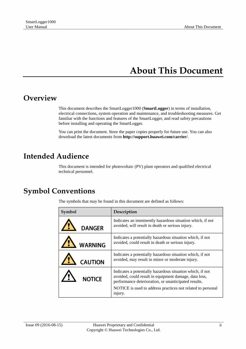
Symbol Conventions
The symbols that may be found in this document are defined as follows:
Symbol Description
Indicates an imminently hazardous situation which, if not
avoided, will result in death or serious injury.
Indicates a potentially hazardous situation which, if not
avoided, could result in death or serious injury.
Indicates a potentially hazardous situation which, if not
avoided, may result in minor or moderate injury.
Indicates a potentially hazardous situation which, if not
avoided, could result in equipment damage, data loss,
performance deterioration, or unanticipated results.
NOTICE is used to address practices not related to personal
injury.
SmartLogger1000
User Manual About This Document
Issue 09 (2016-08-15) Huawei Proprietary and Confidential
Copyright © Huawei Technologies Co., Ltd.
iii
Symbol Description
Calls attention to important information, best practices and
tips.
NOTE is used to address information not related to personal
injury, equipment damage, and environment deterioration.
Change History
Changes between document issues are cumulative. The latest document issue contains all the
changes made in earlier issues.
Issue 09 (2016-08-15)
Added 3.6 Installing the RS485 signal SPD .
Added 4.2 Connecting the PE Cable for the RS485 Signal SPD.
Added 4.3 Connecting the RS485 Signal SPD.
Updated 4.4.1 Connecting the SmartLogger to the SUN2000.
Updated 4.4.2 Connecting the SmartLogger to the SUN8000.
Updated 4.5 Connecting to an EMI.
Updated 4.7 Connecting to an AC Combiner Box.
Updated 4.9 Connecting an Ethernet Network Cable.
Added 6.2.4 Sending a Reset Command to the Inverter.
Added 6.2.32 Resetting the System.
Added 7.11.7 Querying the Inverter Tracking System.
Added 7.11.9 Setting the Inverter LVRT Characteristic Curve.
Added 7.19 IEC103 Devices.
Issue 08 (2015-08-20)
Added 6.2.28 Exporting All Files.
Added 6.2.29 Importing All Files.
Added 7.31 Setting Modbus TCP Parameters.
Issue 07 (2015-01-20)
Added 4.10 Connecting to a PID.
Added PLC information query and parameter settings.
Added PID information query and parameter settings.
Added Custom Devices information query and parameter settings.
SmartLogger1000
User Manual About This Document
Issue 09 (2016-08-15) Huawei Proprietary and Confidential
Copyright © Huawei Technologies Co., Ltd.
iv
Added 7.43 Onsite Test.
Updated 7.44 Device management.
Issue 06 (2014-09-20)
Added 4.7 Connecting to an AC Combiner Box.
Added 6.2.9 Querying AC Combiner Box Information.
Added 6.2.10 Setting Feature Parameters for an AC Combiner Box.
Added 7.5 Querying the Power Station Running Information.
Added 7.13.2 Querying the Performance Data of a Power Meter.
Added 7.32 Setting IEC103 Parameters.
Issue 05 (2014-05-20)
Added 4.6 Connecting the SmartLogger to a Power Meter.
Added 6.2.6 Querying Master SmartLogger Information.
Added 6.2.7 Querying Slave SmartLogger Information.
Added 6.2.8 Querying Power Meter Information.
Added 6.2.20 Setting SmartLogger Contrast.
Added Batch Power-On/Off.
Added 7.3 WebUI Layout.
Added 7.10.1 Querying the Master SmartLogger Running Information.
Added 7.10.2 Querying the Active Alarms of the Master SmartLogger.
Added 7.10.3 Querying the Slave SmartLogger Running Information.
Added 7.29 Setting Power Meter Parameters.
Added 8.2 Application Scenarios.
Added 9.3 Alarms.
Issue 04 (2013-12-01)
This is the fourth official release.
Added Server+Client mode as a NetEco parameter in 6.2.23 Setting Communications
Parameters.
Added address assignments in 6.2.30 Managing Devices.
Added the setting of USB parameters in 7.36.2 Setting USB Parameters.
Updated parts of the web user interface (WebUI).
Issue 03 (2013-09-10)
This issue is the third official release.
SmartLogger1000
User Manual About This Document
Issue 09 (2016-08-15) Huawei Proprietary and Confidential
Copyright © Huawei Technologies Co., Ltd.
v
Compared with the second official release, this document updates some operations and figures
for the LCD and WebUI.
Issue 02 (2013-06-06)
This issue is the second official release.
Issue 01 (2013-04-25)
This issue is the first official release.
Compared with the original draft, this document updates some operations and figures for the
LCD and WebUI.
SmartLogger1000
User Manual Contents
Issue 09 (2016-08-15) Huawei Proprietary and Confidential
Copyright © Huawei Technologies Co., Ltd.
vi
Contents
About This Document .................................................................................................................... ii
1 Safety Precautions ......................................................................................................................... 1
1.1 Precautions .................................................................................................................................................................... 1
1.2 Symbols ........................................................................................................................................................................ 2
2 Overview ......................................................................................................................................... 3
2.1 Product Introduction ..................................................................................................................................................... 3
2.2 Appearance ................................................................................................................................................................... 5
2.3 Monitoring Panel .......................................................................................................................................................... 8
2.4 Typical Cable Connection Scenarios .......................................................................................................................... 11
2.4.1 Scenarios with the Communication Box .................................................................................................................. 11
2.4.2 Scenarios Without the Communication Box ............................................................................................................ 15
3 Installation.................................................................................................................................... 19
3.1 Installation Process ..................................................................................................................................................... 19
3.2 Checking Before Installation ...................................................................................................................................... 21
3.3 Preparing Tools ........................................................................................................................................................... 22
3.4 Determining the Installation Position ......................................................................................................................... 24
3.5 Installing the SmartLogger ......................................................................................................................................... 25
3.5.1 Installing the SmartLogger on a Desk ..................................................................................................................... 25
3.5.2 Mounting the SmartLogger on a Wall ...................................................................................................................... 26
3.5.3 Mounting the SmartLogger Along a Guide Rail ...................................................................................................... 27
3.6 Installing the RS485 signal SPD ................................................................................................................................. 29
4 Electrical Connections ................................................................................................................ 31
4.1 Connection Description .............................................................................................................................................. 31
4.2 Connecting the PE Cable for the RS485 Signal SPD ................................................................................................. 32
4.3 Connecting the RS485 Signal SPD ............................................................................................................................. 33
4.4 Connecting the SmartLogger to Inverters ................................................................................................................... 36
4.4.1 Connecting the SmartLogger to the SUN2000 ........................................................................................................ 36
4.4.2 Connecting the SmartLogger to the SUN8000 ........................................................................................................ 42
4.4.3 Connecting Multiple Inverters to the SmartLogger ................................................................................................. 45
4.5 Connecting to an EMI ................................................................................................................................................. 46
4.6 Connecting the SmartLogger to a Power Meter .......................................................................................................... 48
SmartLogger1000
User Manual Contents
Issue 09 (2016-08-15) Huawei Proprietary and Confidential
Copyright © Huawei Technologies Co., Ltd.
vii
4.7 Connecting to an AC Combiner Box .......................................................................................................................... 49
4.8 Connecting to a PLC ................................................................................................................................................... 51
4.9 Connecting an Ethernet Network Cable ..................................................................................................................... 53
4.10 Connecting to a PID .................................................................................................................................................. 54
4.11 Connecting the SmartLogger to a Ripple Control Receiver ...................................................................................... 55
5 System Operation ........................................................................................................................ 58
5.1 Power-on Process ........................................................................................................................................................ 58
5.2 Setting Initialization Parameters ................................................................................................................................. 59
6 User Interface ............................................................................................................................... 62
6.1 Monitoring Menu Hierarchy ....................................................................................................................................... 62
6.2 Monitoring Operations ................................................................................................................................................ 64
6.2.1 Querying Power Station Information ....................................................................................................................... 64
6.2.2 Querying Inverter Information ................................................................................................................................. 69
6.2.3 Manually Powering On or Off the Inverter on the monitoring panel ....................................................................... 72
6.2.4 Sending a Reset Command to the Inverter ............................................................................................................... 74
6.2.5 Querying Information about the EMI ...................................................................................................................... 76
6.2.6 Querying Master SmartLogger Information ............................................................................................................ 78
6.2.7 Querying Slave SmartLogger Information .............................................................................................................. 80
6.2.8 Querying Power Meter Information ......................................................................................................................... 81
6.2.9 Querying AC Combiner Box Information ............................................................................................................... 83
6.2.10 Setting Feature Parameters for an AC Combiner Box ........................................................................................... 85
6.2.11 Querying PLC Information .................................................................................................................................... 87
6.2.12 Sending a Reset Command to the PLC .................................................................................................................. 90
6.2.13 Querying PID Information ..................................................................................................................................... 92
6.2.14 Setting the PID Module Feature Parameters .......................................................................................................... 94
6.2.15 Manually Powering On or Off the PID on the monitoring panel ........................................................................... 98
6.2.16 Querying Custom Device Information ................................................................................................................. 101
6.2.17 Querying Alarm Records ..................................................................................................................................... 102
6.2.18 Setting the System Language ............................................................................................................................... 106
6.2.19 Setting System Time Parameters ......................................................................................................................... 107
6.2.20 Setting SmartLogger Contrast.............................................................................................................................. 109
6.2.21 Setting the Currency and Currency Factor ........................................................................................................... 111
6.2.22 Changing a Password ........................................................................................................................................... 113
6.2.23 Setting Communications Parameters ................................................................................................................... 116
6.2.24 Restoring Factory Settings ................................................................................................................................... 120
6.2.25 Downloading Data Using a USB Flash Drive ..................................................................................................... 122
6.2.26 Upgrading Firmware by Using a USB Flash Drive ............................................................................................. 123
6.2.27 Batch Upgrade ..................................................................................................................................................... 126
6.2.28 Exporting All Files ............................................................................................................................................... 128
6.2.29 Importing All Files ............................................................................................................................................... 130
6.2.30 Managing Devices ............................................................................................................................................... 131
SmartLogger1000
User Manual Contents
Issue 09 (2016-08-15) Huawei Proprietary and Confidential
Copyright © Huawei Technologies Co., Ltd.
viii
6.2.31 Clearing Data ....................................................................................................................................................... 141
6.2.32 Resetting the System ............................................................................................................................................ 143
6.2.33 Querying Product Information ............................................................................................................................. 145
7 Web User Interface.................................................................................................................... 146
7.1 Preparations for Login .............................................................................................................................................. 146
7.2 Logging In to the WebUI .......................................................................................................................................... 155
7.3 WebUI Layout ........................................................................................................................................................... 156
7.4 WebUI Menu ............................................................................................................................................................. 158
7.5 Querying the Power Station Running Information ................................................................................................... 161
7.6 Querying Current Active Alarms in the System ........................................................................................................ 162
7.7 Querying System Electric Energy Yields .................................................................................................................. 163
7.8 Querying System Performance Data ......................................................................................................................... 167
7.9 Querying Device Running Information .................................................................................................................... 169
7.10 SmartLogger ........................................................................................................................................................... 170
7.10.1 Querying the Master SmartLogger Running Information .................................................................................... 170
7.10.2 Querying the Active Alarms of the Master SmartLogger .................................................................................... 171
7.10.3 Querying the Slave SmartLogger Running Information ...................................................................................... 172
7.11 Inverters .................................................................................................................................................................. 173
7.11.1 Querying Running Information of Inverters ........................................................................................................ 173
7.11.2 Manually Sending Powering On/Off Instructions to an Inverter ......................................................................... 174
7.11.3 Querying the Active Alarms of an Inverter .......................................................................................................... 174
7.11.4 Querying the Performance Data of an Inverter .................................................................................................... 175
7.11.5 Querying the Electric Energy Yield of Inverters .................................................................................................. 178
7.11.6 Setting the Running Parameters of an Inverter .................................................................................................... 181
7.11.7 Querying the Inverter Tracking System ............................................................................................................... 184
7.11.8 Setting the Power Grid Standard Code for an Inverter ........................................................................................ 185
7.11.9 Setting the Inverter LVRT Characteristic Curve .................................................................................................. 187
7.12 EMI ......................................................................................................................................................................... 189
7.12.1 Querying the EMI Running Information ............................................................................................................. 189
7.12.2 Querying the Performance Data of an EMI ......................................................................................................... 189
7.13 Power Meter............................................................................................................................................................ 192
7.13.1 Viewing the Power Meter Running Information .................................................................................................. 192
7.13.2 Querying the Performance Data of a Power Meter .............................................................................................. 192
7.14 DL/T645 Power Meter ............................................................................................................................................ 195
7.14.1 Querying the DL/T645 Power Meter Running Information ................................................................................ 195
7.14.2 Querying the DL/T645 Power Meter Performance Data ..................................................................................... 195
7.14.3 Setting DL/T645 Power Meter Running Parameters ........................................................................................... 198
7.15 AC Combiner Box .................................................................................................................................................. 198
7.15.1 Querying Running Information of an AC Combiner Box .................................................................................... 198
7.15.2 Querying the Active Alarms of an AC Combiner Box ......................................................................................... 199
7.15.3 Querying the Performance Data of an AC Combiner Box ................................................................................... 200
SmartLogger1000
User Manual Contents
Issue 09 (2016-08-15) Huawei Proprietary and Confidential
Copyright © Huawei Technologies Co., Ltd.
ix
7.15.4 Setting Running Parameters for an AC Combiner Box ....................................................................................... 202
7.16 PLC ......................................................................................................................................................................... 204
7.16.1 Querying the Running Information of a PLC ...................................................................................................... 204
7.16.2 Setting Running Parameters for a PLC ................................................................................................................ 204
7.16.3 Setting the PLC STA List ..................................................................................................................................... 205
7.16.4 Managing PLC ESNs ........................................................................................................................................... 206
7.17 PID Module ............................................................................................................................................................ 206
7.17.1 Querying PID Module Running Information ....................................................................................................... 206
7.17.2 Querying PID Module Active Alarms .................................................................................................................. 207
7.17.3 Querying the PID Module Performance Data ...................................................................................................... 208
7.17.4 Setting the PID Module Running Parameters ...................................................................................................... 210
7.18 Custom Devices ...................................................................................................................................................... 213
7.18.1 Querying Running Information of Custom Devices ............................................................................................ 213
7.18.2 Querying Teleindication Information ................................................................................................................... 213
7.18.3 Querying Telemetering Information .................................................................................................................... 214
7.18.4 Setting Telecontrol Parameters ............................................................................................................................ 215
7.18.5 Setting Teleadjust Parameters .............................................................................................................................. 215
7.19 IEC103 Devices ...................................................................................................................................................... 216
7.19.1 Querying IEC103 Device Running Information .................................................................................................. 216
7.19.2 Querying the IEC103 Device Teleindication Information ................................................................................... 217
7.19.3 Querying the IEC103 Device Telemetering Information ..................................................................................... 218
7.19.4 Setting the IEC103 Device Telecontrol Parameters ............................................................................................. 218
7.19.5 Setting the IEC103 Device Teleadjust Parameters ............................................................................................... 219
7.20 Querying Historical Alarms .................................................................................................................................... 220
7.21 Querying Operation Logs ....................................................................................................................................... 221
7.22 Exporting Data ........................................................................................................................................................ 222
7.23 Set the Data and Time ............................................................................................................................................. 225
7.24 Setting Plant Information ........................................................................................................................................ 226
7.25 Setting Currency Parameters................................................................................................................................... 227
7.26 Setting Ethernet Parameters .................................................................................................................................... 228
7.27 Setting RS485 Parameters ...................................................................................................................................... 229
7.28 Setting EMI Parameters .......................................................................................................................................... 230
7.29 Setting Power Meter Parameters ............................................................................................................................. 232
7.30 Setting NetEco Parameters ..................................................................................................................................... 234
7.31 Setting Modbus TCP Parameters ............................................................................................................................ 235
7.32 Setting IEC103 Parameters ..................................................................................................................................... 236
7.33 Setting IEC104 Parameters ..................................................................................................................................... 237
7.34 Setting FTP Parameters ........................................................................................................................................... 238
7.35 Setting Email Parameters ........................................................................................................................................ 239
7.36 Port Settings ............................................................................................................................................................ 240
7.36.1 Setting DO Parameters......................................................................................................................................... 241
7.36.2 Setting USB Parameters ....................................................................................................................................... 244
SmartLogger1000
User Manual Contents
Issue 09 (2016-08-15) Huawei Proprietary and Confidential
Copyright © Huawei Technologies Co., Ltd.
x
7.37 Dry contact remote shutdown ................................................................................................................................. 245
7.38 Firmware Upgrade .................................................................................................................................................. 247
7.39 Viewing Product Information ................................................................................................................................. 249
7.40 Security Settings ..................................................................................................................................................... 249
7.41 System Reset ........................................................................................................................................................... 250
7.42 Exporting Device Logs ........................................................................................................................................... 251
7.43 Onsite Test .............................................................................................................................................................. 252
7.44 Device management ................................................................................................................................................ 254
7.44.1 Connecting a Device ............................................................................................................................................ 254
7.44.2 Device Name ....................................................................................................................................................... 256
7.44.3 Exporting Parameters ........................................................................................................................................... 257
7.44.4 Resetting Alarms .................................................................................................................................................. 258
8 Grid Dispatch ............................................................................................................................. 260
8.1 Power Grid Dispatching Modes ................................................................................................................................ 260
8.1.1 Active Power Control............................................................................................................................................. 260
8.1.2 Reactive Power Control ......................................................................................................................................... 261
8.2 Application Scenarios ............................................................................................................................................... 262
8.2.1 Local Dispatching .................................................................................................................................................. 262
8.2.2 Dry Contact Dispatching ....................................................................................................................................... 268
8.2.3 AI/DI Scheduling ................................................................................................................................................... 271
8.2.4 Communication Scheduling ................................................................................................................................... 276
9 Maintenance ............................................................................................................................... 279
9.1 Daily Maintenance .................................................................................................................................................... 279
9.2 Troubleshooting ........................................................................................................................................................ 279
9.3 Alarms ....................................................................................................................................................................... 281
10 Disposing of the SmartLogger .............................................................................................. 287
11 Technical Specifications ........................................................................................................ 288
A Monitoring User List ............................................................................................................... 290
B Acronyms and Abbreviations ................................................................................................ 291
SmartLogger1000
User Manual 1 Safety Precautions
Issue 09 (2016-08-15) Huawei Proprietary and Confidential
Copyright © Huawei Technologies Co., Ltd.
1
1 Safety Precautions
Read the safety precautions carefully. Otherwise, human injury and equipment damage may
occur.
1.1 Precautions
This topic describes the precautions for installing and operating the SmartLogger.
Personnel Requirements Only qualified and trained electrical technicians are allowed to install and operate the
SmartLogger.
Operation personnel should understand the composition and working principles of the
PV grid-tied power generating system and local regulations.
Read this document thoroughly before operations. Huawei shall not be liable for any
consequence caused by violation of the storage, transportation, installation, and operation
regulations specified in this document.
Identification Protection The signs on the SmartLogger shell specify important information about secure
operations. Do not damage the signs.
The nameplate attached to the bottom of the SmartLogger lists the SmartLogger
parameters. Do not damage the nameplate.
Installation Before installing the SmartLogger, ensure that it is not connected or energized.
Install the SmartLogger in well-ventilated environments to ensure system performance.
Ensure that the heat dissipation holes of the SmartLogger are not blocked.
SmartLogger1000
User Manual 1 Safety Precautions
Issue 09 (2016-08-15) Huawei Proprietary and Confidential
Copyright © Huawei Technologies Co., Ltd.
2
Do not move the components inside the shelf except for the wiring terminals at the
bottom.
Operation
Strictly comply with the safety precautions in this document and associated documents to
operate the SmartLogger.
When operating the SmartLogger, follow local laws and regulations.
Maintenance and Replacement A faulty SmartLogger requires overall maintenance. Contact the dealer if any fault
occurs in the SmartLogger shelf.
Maintain the SmartLogger after you get familiar with this document and tools and testing
equipment are available.
When maintaining the SmartLogger, wear ESD gloves and comply with ESD
precautions.
1.2 Symbols
The following table describes all symbols on the SmartLogger.
Symbol Name Meaning
CE certification label This product complies with
the Conformite Europeenne
(CE) certification
standards.
VCCI certification label This product complies with
Voluntary Control Council
for Interference by
Information Technology
Equipment (VCCI)
certification standards.
Environmentally friendly
use period (EFUP) label
This product does not
pollute the environment
during a specified period.
EU waste electrical and
electronic equipment
(WEEE) label
Do not dispose of the
SmartLogger as household
garbage. For details about
how to deal with the
undesirable SmartLogger,
refer to 10 Disposing of the
SmartLogger.
SmartLogger1000
User Manual 2 Overview
Issue 09 (2016-08-15) Huawei Proprietary and Confidential
Copyright © Huawei Technologies Co., Ltd.
3
2 Overview
This topic describes the SmartLogger in terms of functions, networking applications, product
features, appearance, and the monitoring panel.
2.1 Product Introduction
This section describes the SmartLogger in terms of functions, networking applications, and
product features.
Functions
The SmartLogger is dedicated for monitoring and managing the PV power generating system.
It converges all ports, converts protocols, collects and stores data, and centrally monitors and
maintains the PV power generating system.
Networking
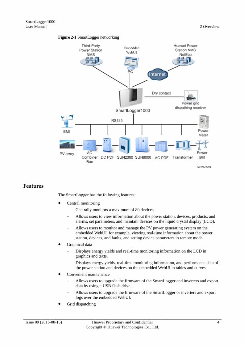
The SmartLogger applies to a PV system.
It can monitor Huawei inverters, AC combiner boxes, PID, and other devices.
It supports third-party devices such as inverters, environment monitoring instruments,
AC combiner boxes, box-type transformers, and smart meters that use the standard
Modbus protocol or provide RS485 ports.
It can simultaneously connect to the Huawei and third-party network management
systems by using the Modbus-TCP and IEC104 protocols.
It can connect to a multi-functional power meter over DLT645.
The SmartLogger networking is shown in Figure 2-1.
SmartLogger1000
User Manual 2 Overview
Issue 09 (2016-08-15) Huawei Proprietary and Confidential
Copyright © Huawei Technologies Co., Ltd.
4
Figure 2-1 SmartLogger networking
Features
The SmartLogger has the following features:
Central monitoring
− Centrally monitors a maximum of 80 devices.
− Allows users to view information about the power station, devices, products, and
alarms, set parameters, and maintain devices on the liquid crystal display (LCD).
− Allows users to monitor and manage the PV power generating system on the
embedded WebUI, for example, viewing real-time information about the power
station, devices, and faults, and setting device parameters in remote mode.
Graphical data
− Displays energy yields and real-time monitoring information on the LCD in
graphics and texts.
− Displays energy yields, real-time monitoring information, and performance data of
the power station and devices on the embedded WebUI in tables and curves.
Convenient maintenance
− Allows users to upgrade the firmware of the SmartLogger and inverters and export
data by using a USB flash drive.
− Allows users to upgrade the firmware of the SmartLogger or inverters and export
logs over the embedded WebUI.
Grid dispatching
SmartLogger1000
User Manual 2 Overview
Issue 09 (2016-08-15) Huawei Proprietary and Confidential
Copyright © Huawei Technologies Co., Ltd.
5
Supports power grid dispatching: active power reduction and reactive power
compensation.
Intelligent management
− Automatically scans and identifies Huawei inverters and AC combiner boxes and
supports protocol conversion for third-party devices
− Supports access from third-party devices that use the standard Modbus-RTU
protocol.
− Automatically assigns RS485 addresses to the connected inverters and allows for
adjusting RS485 addresses based on device sequence numbers to facilitate remote
configuration and maintenance.
− Supports remote setting of inverter parameters and synchronizes the parameters of
one inverter to other inverters in batches.
Remote maintenance
− Supports connection to Huawei NetEco and a third-party network management
system (NMS) simultaneously using Modbus-TCP and IEC104 to remotely manage
all devices.
− Allows users to access a third-party NMS over the File Transfer Protocol (FTP).
− Sends energy yield and fault information to users by emails.
2.2 Appearance
This topic describes the SmartLogger in terms of its appearance and specifications.
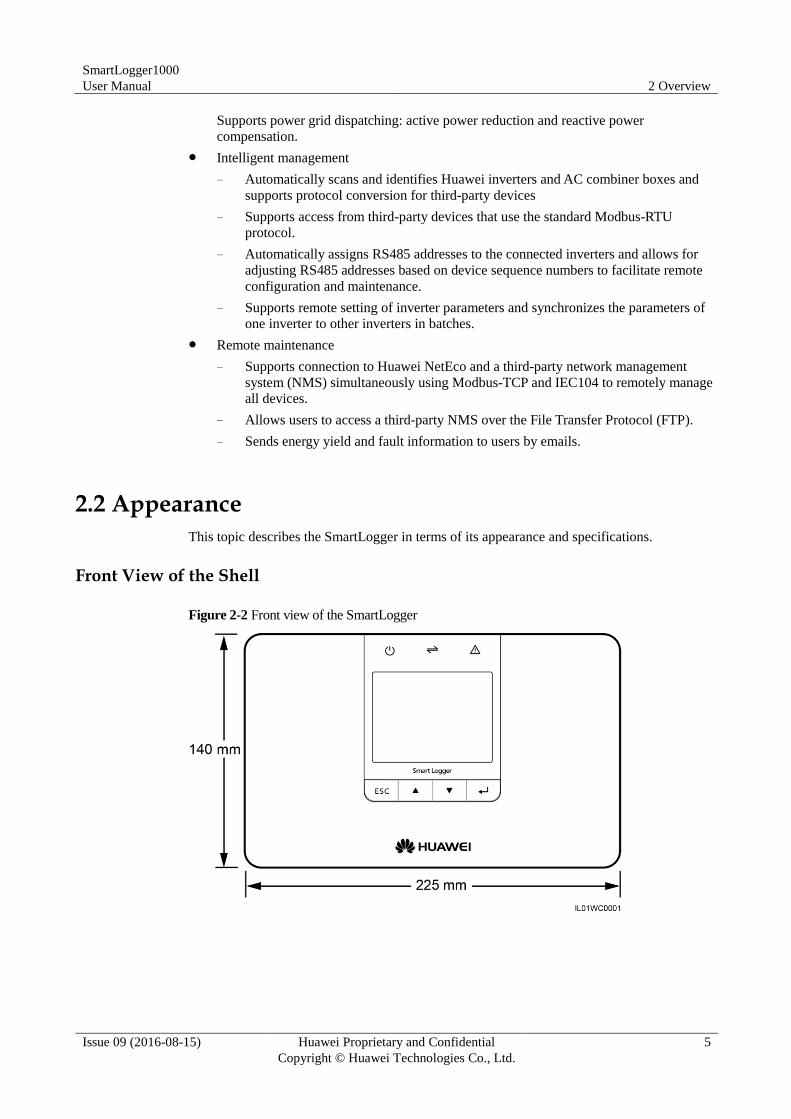
Front View of the Shell
Figure 2-2 Front view of the SmartLogger
SmartLogger1000
User Manual 2 Overview
Issue 09 (2016-08-15) Huawei Proprietary and Confidential
Copyright © Huawei Technologies Co., Ltd.
6
The LCD on the SmartLogger monitoring panel displays information about the power site, devices,
alarms, and products. This topic describes how to set parameters and maintain devices over the
monitoring panel.
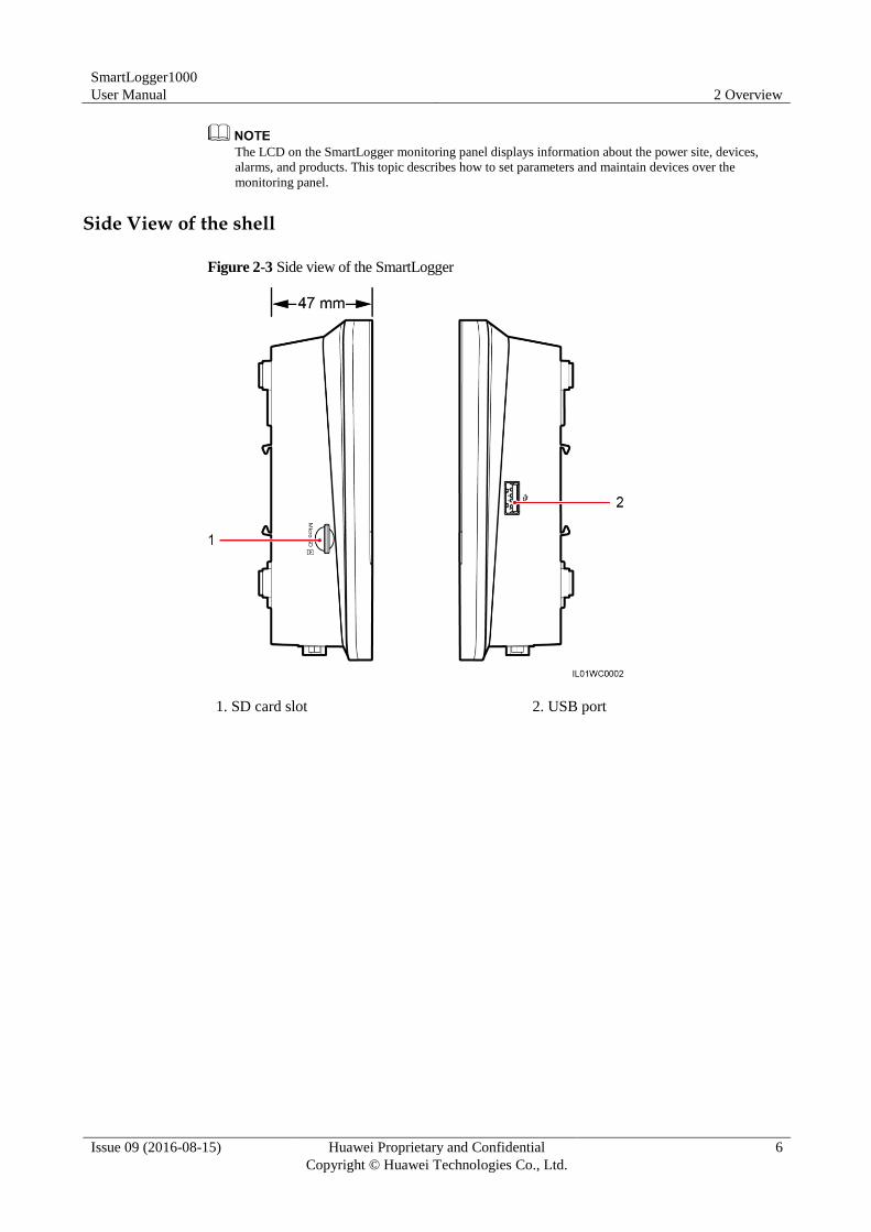
Side View of the shell
Figure 2-3 Side view of the SmartLogger
1. SD card slot 2. USB port
SmartLogger1000
User Manual 2 Overview
Issue 09 (2016-08-15) Huawei Proprietary and Confidential
Copyright © Huawei Technologies Co., Ltd.
7
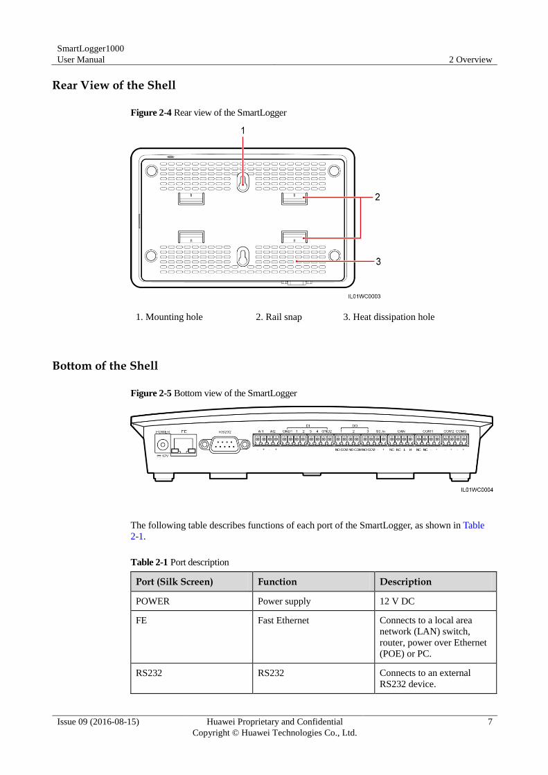
Rear View of the Shell
Figure 2-4 Rear view of the SmartLogger
1. Mounting hole 2. Rail snap 3. Heat dissipation hole
Bottom of the Shell
Figure 2-5 Bottom view of the SmartLogger
The following table describes functions of each port of the SmartLogger, as shown in Table
2-1.
Table 2-1 Port description
Port (Silk Screen) Function Description
POWER Power supply 12 V DC
FE Fast Ethernet Connects to a local area
network (LAN) switch,
router, power over Ethernet
(POE) or PC.
RS232 RS232 Connects to an external
RS232 device.
SmartLogger1000
User Manual 2 Overview
Issue 09 (2016-08-15) Huawei Proprietary and Confidential
Copyright © Huawei Technologies Co., Ltd.
8
Port (Silk Screen) Function Description
AI Analog input 4–20 mA and 0–20 mA
current input (active),
reserved.
DI Digital input Connects to a dry contact
input.
DO Digital output Relay output
S0.In Connects to a pulse output
power meter
Reserved
CAN CAN Reserved
COM1-COM3 RS485 Supports three RS485 ports
that can connect to devices
such as the inverter and
environmental monitoring
instrument (EMI).
2.3 Monitoring Panel
This topic describes the monitoring panel, including an LCD, indicators, buttons, and the
default page.
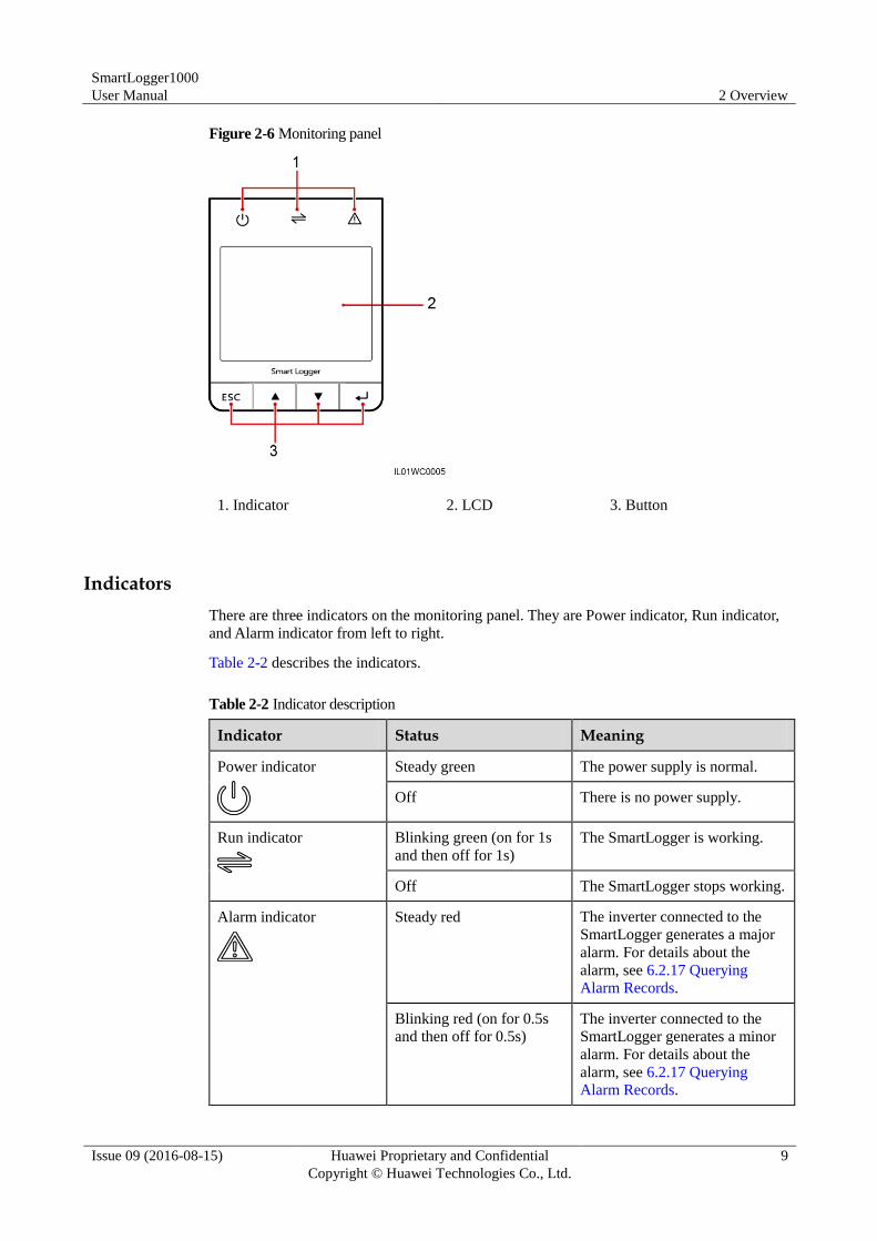
Monitoring panel
The monitoring panel provides one LCD, three indicators, and four buttons, as shown in
Figure 2-6.
SmartLogger1000
User Manual 2 Overview
Issue 09 (2016-08-15) Huawei Proprietary and Confidential
Copyright © Huawei Technologies Co., Ltd.
9
Figure 2-6 Monitoring panel
1. Indicator 2. LCD 3. Button
Indicators
There are three indicators on the monitoring panel. They are Power indicator, Run indicator,
and Alarm indicator from left to right.
Table 2-2 describes the indicators.
Table 2-2 Indicator description
Indicator Status Meaning
Power indicator
Steady green The power supply is normal.
Off There is no power supply.
Run indicator
Blinking green (on for 1s
and then off for 1s)
The SmartLogger is working.
Off The SmartLogger stops working.
Alarm indicator
Steady red The inverter connected to the
SmartLogger generates a major
alarm. For details about the
alarm, see 6.2.17 Querying
Alarm Records.
Blinking red (on for 0.5s
and then off for 0.5s)
The inverter connected to the
SmartLogger generates a minor
alarm. For details about the
alarm, see 6.2.17 Querying Alarm Records.
SmartLogger1000
User Manual 2 Overview
Issue 09 (2016-08-15) Huawei Proprietary and Confidential
Copyright © Huawei Technologies Co., Ltd.
10
Indicator Status Meaning
Blinking red (on for 1s and
then off for 4s)
The inverter connected to the
SmartLogger generates a
warning. For details about the
warning, see 6.2.17 Querying
Alarm Records.
Off The inverter connected to the
SmartLogger is working
normally.
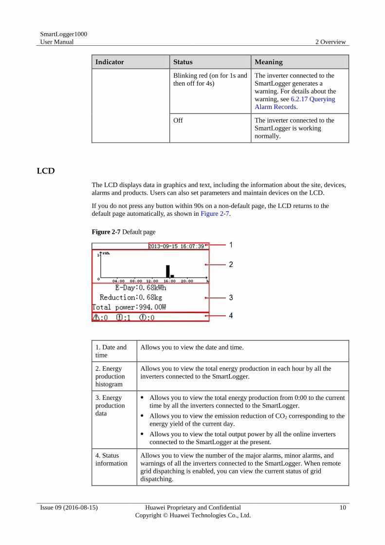
LCD
The LCD displays data in graphics and text, including the information about the site, devices,
alarms and products. Users can also set parameters and maintain devices on the LCD.
If you do not press any button within 90s on a non-default page, the LCD returns to the
default page automatically, as shown in Figure 2-7.
Figure 2-7 Default page
1. Date and
time
Allows you to view the date and time.
2. Energy
production
histogram
Allows you to view the total energy production in each hour by all the
inverters connected to the SmartLogger.
3. Energy
production
data
Allows you to view the total energy production from 0:00 to the current
time by all the inverters connected to the SmartLogger.
Allows you to view the emission reduction of CO2 corresponding to the
energy yield of the current day.
Allows you to view the total output power by all the online inverters
connected to the SmartLogger at the present.
4. Status
information
Allows you to view the number of the major alarms, minor alarms, and
warnings of all the inverters connected to the SmartLogger. When remote
grid dispatching is enabled, you can view the current status of grid
dispatching.
SmartLogger1000
User Manual 2 Overview
Issue 09 (2016-08-15) Huawei Proprietary and Confidential
Copyright © Huawei Technologies Co., Ltd.
11
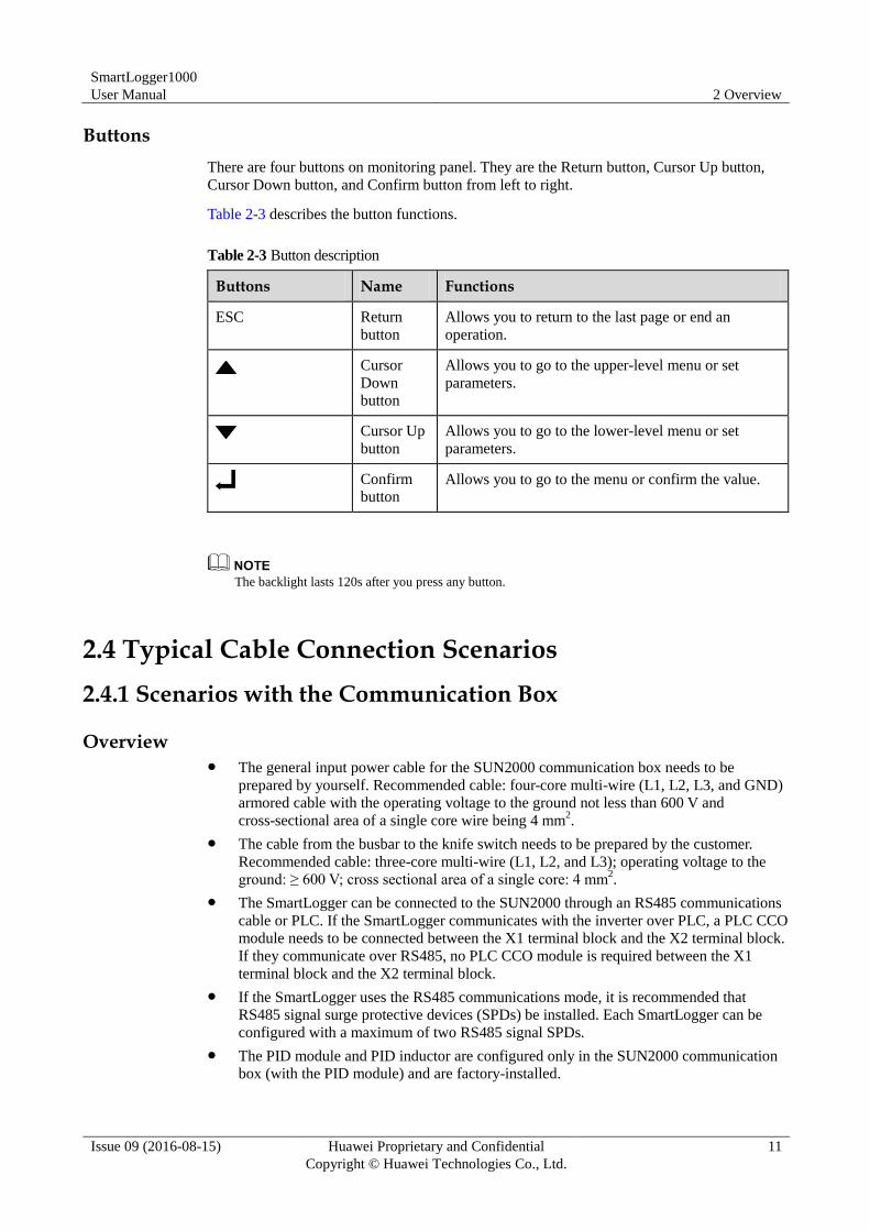
Buttons
There are four buttons on monitoring panel. They are the Return button, Cursor Up button,
Cursor Down button, and Confirm button from left to right.
Table 2-3 describes the button functions.
Table 2-3 Button description
Buttons Name Functions
ESC Return
button
Allows you to return to the last page or end an
operation.
Cursor
Down
button
Allows you to go to the upper-level menu or set
parameters.
Cursor Up
button
Allows you to go to the lower-level menu or set
parameters.
Confirm
button Allows you to go to the menu or confirm the value.
The backlight lasts 120s after you press any button.
2.4 Typical Cable Connection Scenarios
2.4.1 Scenarios with the Communication Box
Overview The general input power cable for the SUN2000 communication box needs to be
prepared by yourself. Recommended cable: four-core multi-wire (L1, L2, L3, and GND)
armored cable with the operating voltage to the ground not less than 600 V and
cross-sectional area of a single core wire being 4 mm2.
The cable from the busbar to the knife switch needs to be prepared by the customer.
Recommended cable: three-core multi-wire (L1, L2, and L3); operating voltage to the
ground: ≥ 600 V; cross sectional area of a single core: 4 mm2.
The SmartLogger can be connected to the SUN2000 through an RS485 communications
cable or PLC. If the SmartLogger communicates with the inverter over PLC, a PLC CCO
module needs to be connected between the X1 terminal block and the X2 terminal block.
If they communicate over RS485, no PLC CCO module is required between the X1
terminal block and the X2 terminal block.
If the SmartLogger uses the RS485 communications mode, it is recommended that
RS485 signal surge protective devices (SPDs) be installed. Each SmartLogger can be
configured with a maximum of two RS485 signal SPDs.
The PID module and PID inductor are configured only in the SUN2000 communication
box (with the PID module) and are factory-installed.
SmartLogger1000
User Manual 2 Overview
Issue 09 (2016-08-15) Huawei Proprietary and Confidential
Copyright © Huawei Technologies Co., Ltd.
12
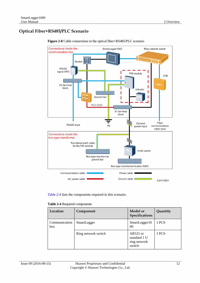
Optical Fiber+RS485/PLC Scenario
Figure 2-8 Cable connections in the optical fiber+RS485/PLC scenario
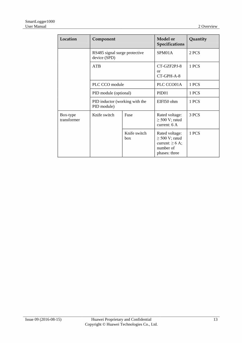
Table 2-4 lists the components required in this scenario.
Table 2-4 Required components
Location Component Model or Specifications
Quantity
Communication
box
SmartLogger SmartLogger10
00
1 PCS
Ring network switch AR531 or
standard 1 U
ring network
switch
1 PCS
SmartLogger1000
User Manual 2 Overview
Issue 09 (2016-08-15) Huawei Proprietary and Confidential
Copyright © Huawei Technologies Co., Ltd.
13
Location Component Model or Specifications
Quantity
RS485 signal surge protective
device (SPD)
SPM01A 2 PCS
ATB CT-GZF2PJ-8
or
CT-GPH-A-8
1 PCS
PLC CCO module PLC CCO01A 1 PCS
PID module (optional) PID01 1 PCS
PID inductor (working with the
PID module)
EIFI50 ohm 1 PCS
Box-type
transformer
Knife switch Fuse Rated voltage:
≥ 500 V; rated
current: 6 A
3 PCS
Knife switch
box
Rated voltage:
≥ 500 V; rated
current: ≥ 6 A;
number of
phases: three
1 PCS
SmartLogger1000
User Manual 2 Overview
Issue 09 (2016-08-15) Huawei Proprietary and Confidential
Copyright © Huawei Technologies Co., Ltd.
14
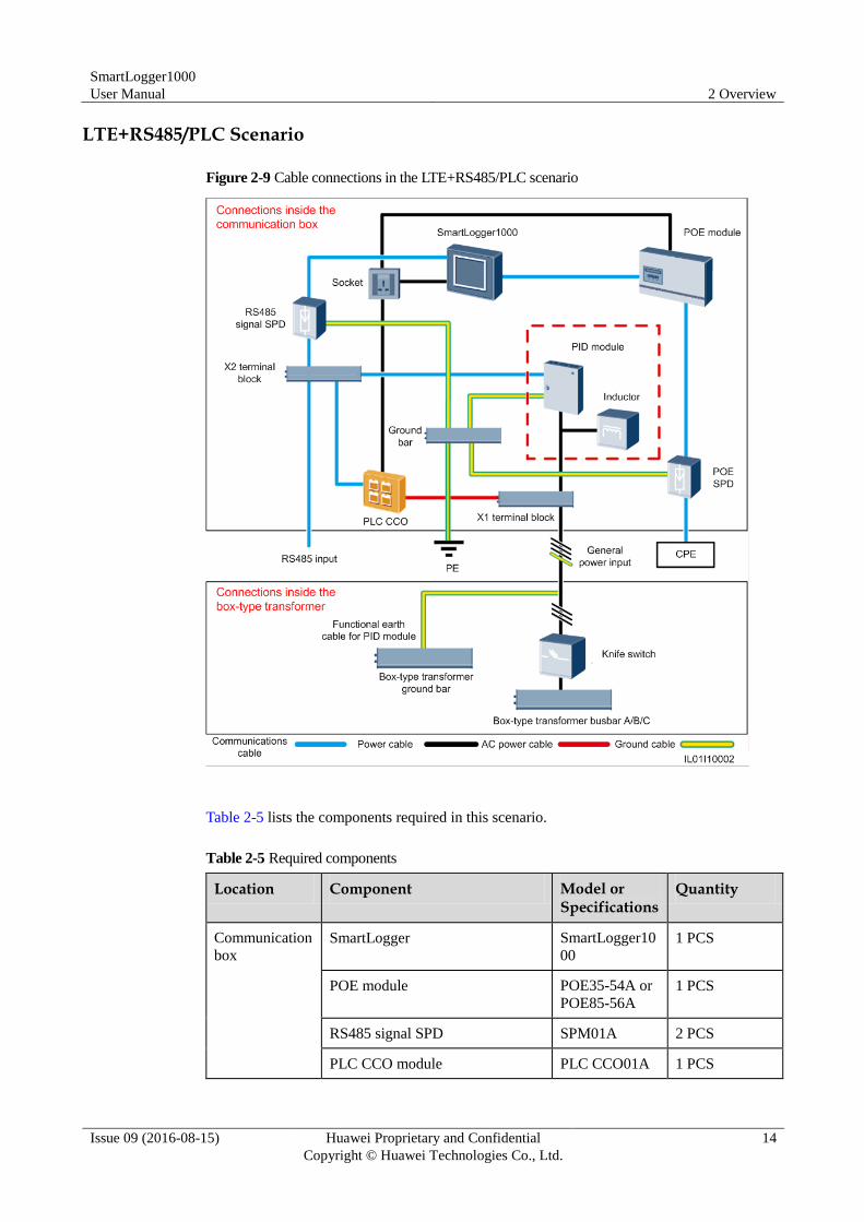
LTE+RS485/PLC Scenario
Figure 2-9 Cable connections in the LTE+RS485/PLC scenario
Table 2-5 lists the components required in this scenario.
Table 2-5 Required components
Location Component Model or Specifications
Quantity
Communication
box
SmartLogger SmartLogger10
00
1 PCS
POE module POE35-54A or
POE85-56A
1 PCS
RS485 signal SPD SPM01A 2 PCS
PLC CCO module PLC CCO01A 1 PCS
SmartLogger1000
User Manual 2 Overview
Issue 09 (2016-08-15) Huawei Proprietary and Confidential
Copyright © Huawei Technologies Co., Ltd.
15
Location Component Model or Specifications
Quantity
PID module (optional) PID01 1 PCS
PID inductor (working with the
PID module)
EIFI50ohm 1 PCS
POE SPD POE-2A 1 PCS
Box-type
transformer
Knife switch Fuse Rated voltage:
≥ 500 V; rated
current: 6 A
3 PCS
Knife switch
box
Rated voltage:
≥ 500 V; rated
current: ≥ 6 A;
number of
phases: three
1 PCS
Outside the
communication
box and
box-type
transformer
CPE N/A 1 PCS
2.4.2 Scenarios Without the Communication Box
Overview The cable from the busbar to the knife switch needs to be prepared by yourself.
Recommended cable: three-core multi-wire (L1, L2, and L3) cable with the operating
voltage to the ground not less than 600 V and the cross sectional area of a single core
wire being 4 mm2.
The cable from the knife switch to the miniature circuit breaker (MCB) needs to be
prepared by yourself. Recommended cable: three-core multi-wire (L1, L2, and L3) cable
with the operating voltage to the ground not less than 600 V and the cross sectional area
of a single core wire being 4 mm2.
If the SmartLogger communicates with the inverter over PLC, a PLC CCO module needs
to be connected. If they communicate over RS485, no PLC CCO module is required.
SmartLogger1000
User Manual 2 Overview
Issue 09 (2016-08-15) Huawei Proprietary and Confidential
Copyright © Huawei Technologies Co., Ltd.
16
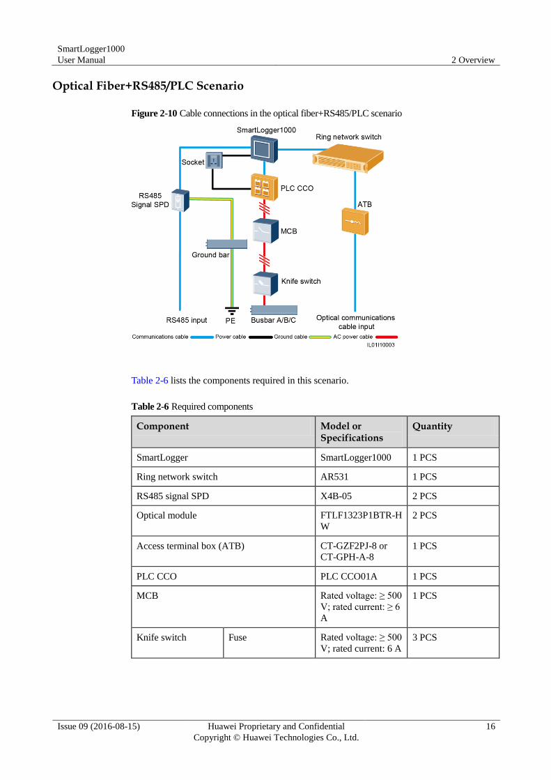
Optical Fiber+RS485/PLC Scenario
Figure 2-10 Cable connections in the optical fiber+RS485/PLC scenario
Table 2-6 lists the components required in this scenario.
Table 2-6 Required components
Component Model or Specifications
Quantity
SmartLogger SmartLogger1000 1 PCS
Ring network switch AR531 1 PCS
RS485 signal SPD X4B-05 2 PCS
Optical module FTLF1323P1BTR-H
W
2 PCS
Access terminal box (ATB) CT-GZF2PJ-8 or
CT-GPH-A-8 1 PCS
PLC CCO PLC CCO01A 1 PCS
MCB Rated voltage: ≥ 500
V; rated current: ≥ 6
A
1 PCS
Knife switch Fuse Rated voltage: ≥ 500
V; rated current: 6 A
3 PCS
SmartLogger1000
User Manual 2 Overview
Issue 09 (2016-08-15) Huawei Proprietary and Confidential
Copyright © Huawei Technologies Co., Ltd.
17
Component Model or Specifications
Quantity
Knife switch box Rated voltage: ≥ 500
V; rated current: ≥ 6
A; number of
phases: three
1 PCS
Socket Matching with the
power adapter
1 PCS
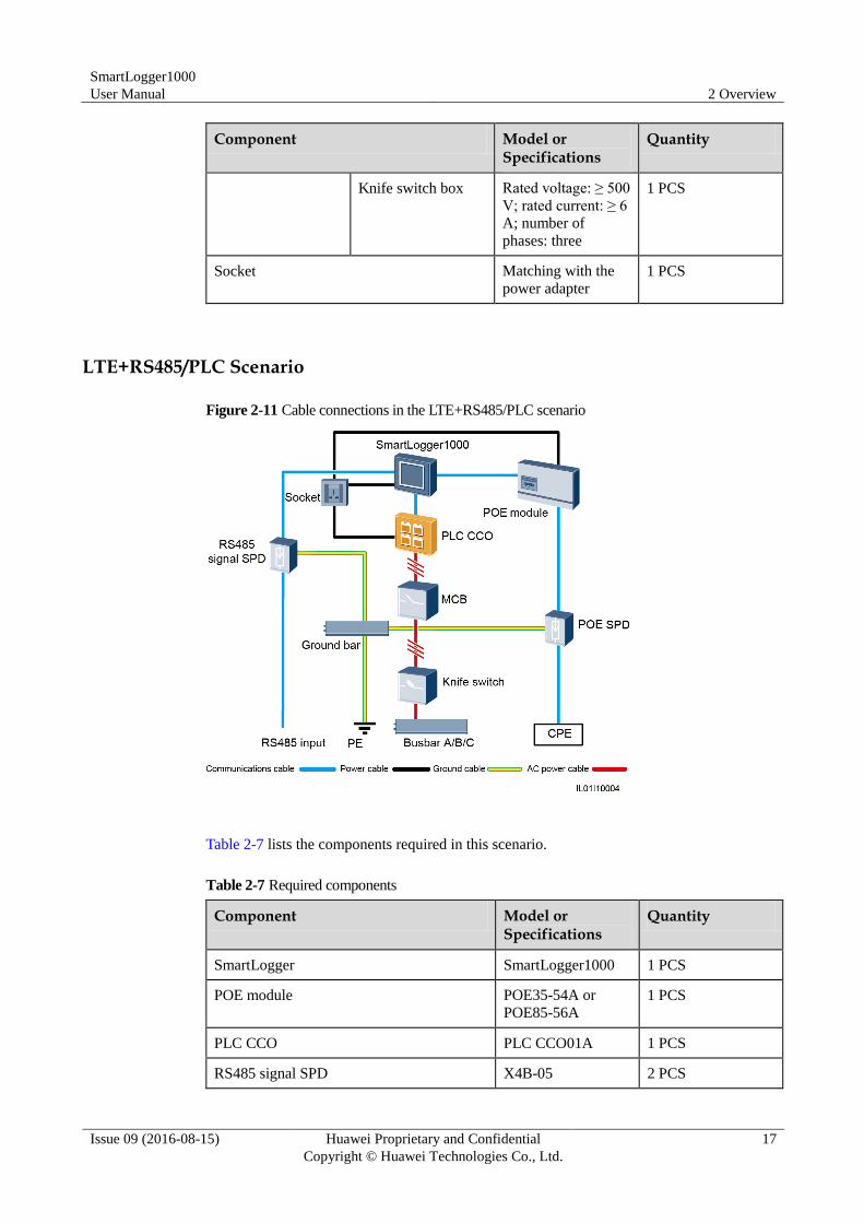
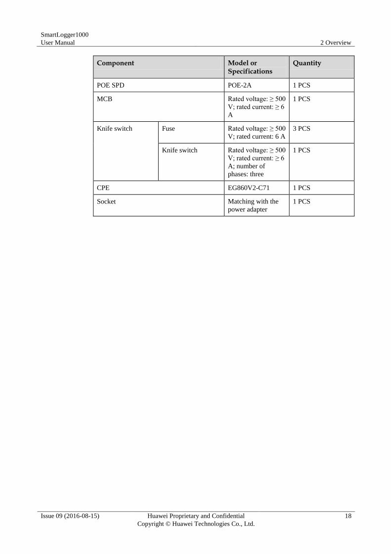
LTE+RS485/PLC Scenario
Figure 2-11 Cable connections in the LTE+RS485/PLC scenario
Table 2-7 lists the components required in this scenario.
Table 2-7 Required components
Component Model or Specifications
Quantity
SmartLogger SmartLogger1000 1 PCS
POE module POE35-54A or
POE85-56A
1 PCS
PLC CCO PLC CCO01A 1 PCS
RS485 signal SPD X4B-05 2 PCS
SmartLogger1000
User Manual 2 Overview
Issue 09 (2016-08-15) Huawei Proprietary and Confidential
Copyright © Huawei Technologies Co., Ltd.
18
Component Model or Specifications
Quantity
POE SPD POE-2A 1 PCS
MCB Rated voltage: ≥ 500
V; rated current: ≥ 6
A
1 PCS
Knife switch Fuse Rated voltage: ≥ 500
V; rated current: 6 A
3 PCS
Knife switch Rated voltage: ≥ 500
V; rated current: ≥ 6
A; number of
phases: three
1 PCS
CPE EG860V2-C71 1 PCS
Socket Matching with the
power adapter
1 PCS
SmartLogger1000
User Manual 3 Installation
Issue 09 (2016-08-15) Huawei Proprietary and Confidential
Copyright © Huawei Technologies Co., Ltd.
19
3 Installation
This topic describes how to install the SmartLogger.
Context
Install the SmartLogger in an appropriate position and surface.
Do not store the SmartLogger in areas with flammable or explosive materials.
Do not install the SmartLogger on flammable building materials.
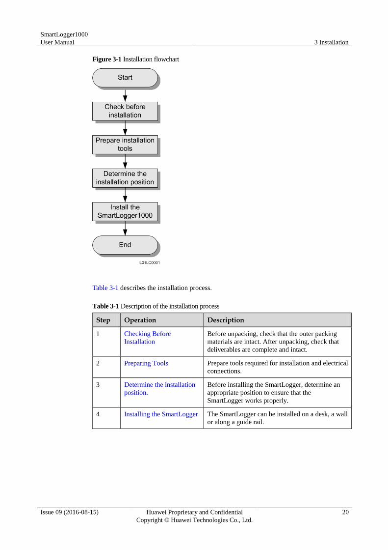
3.1 Installation Process
This topic describes the SmartLogger installation process.
The SmartLogger installation process is shown in Figure 3-1.
SmartLogger1000
User Manual 3 Installation
Issue 09 (2016-08-15) Huawei Proprietary and Confidential
Copyright © Huawei Technologies Co., Ltd.
20
Figure 3-1 Installation flowchart
Table 3-1 describes the installation process.
Table 3-1 Description of the installation process
Step Operation Description
1 Checking Before
Installation
Before unpacking, check that the outer packing
materials are intact. After unpacking, check that
deliverables are complete and intact.
2 Preparing Tools Prepare tools required for installation and electrical
connections.
3 Determine the installation
position.
Before installing the SmartLogger, determine an
appropriate position to ensure that the
SmartLogger works properly.
4 Installing the SmartLogger The SmartLogger can be installed on a desk, a wall
or along a guide rail.
SmartLogger1000
User Manual 3 Installation
Issue 09 (2016-08-15) Huawei Proprietary and Confidential
Copyright © Huawei Technologies Co., Ltd.
21
3.2 Checking Before Installation
Checking Outer Packing Materials
Check the outer packing materials for damage before unpack the SmartLogger, such as holes
and cracks. If any damage is found, do not unpack the SmartLogger and contact the dealer as
soon as possible.
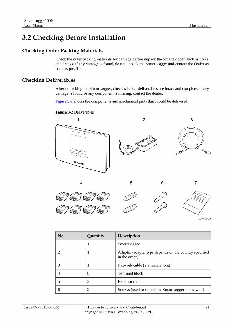
Checking Deliverables
After unpacking the SmartLogger, check whether deliverables are intact and complete. If any
damage is found or any component is missing, contact the dealer.
Figure 3-2 shows the components and mechanical parts that should be delivered.
Figure 3-2 Deliverables
No. Quantity Description
1 1 SmartLogger
2 1 Adapter (adapter type depends on the country specified
in the order)
3 1 Network cable (2.2 meters long)
4 8 Terminal block
5 2 Expansion tube
6 2 Screws (used to secure the SmartLogger to the wall)
SmartLogger1000
User Manual 3 Installation
Issue 09 (2016-08-15) Huawei Proprietary and Confidential
Copyright © Huawei Technologies Co., Ltd.
22
No. Quantity Description
7 1 Auxiliary documents
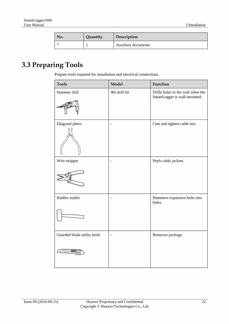
3.3 Preparing Tools
Prepare tools required for installation and electrical connections.
Tools Model Function
Hammer drill
Ф6 drill bit Drills holes in the wall when the
SmartLogger is wall-mounted.
Diagonal pliers
- Cuts and tighten cable ties.
Wire stripper
- Peels cable jackets.
Rubber mallet
- Hammers expansion bolts into
holes.
Guarded blade utility knife
- Removes package.
SmartLogger1000
User Manual 3 Installation
Issue 09 (2016-08-15) Huawei Proprietary and Confidential
Copyright © Huawei Technologies Co., Ltd.
23
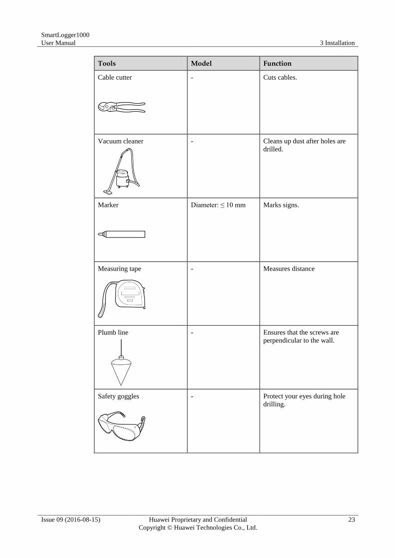
Tools Model Function
Cable cutter
- Cuts cables.
Vacuum cleaner
- Cleans up dust after holes are
drilled.
Marker
Diameter: ≤ 10 mm Marks signs.
Measuring tape
- Measures distance
Plumb line
- Ensures that the screws are
perpendicular to the wall.
Safety goggles
- Protect your eyes during hole
drilling.
SmartLogger1000
User Manual 3 Installation
Issue 09 (2016-08-15) Huawei Proprietary and Confidential
Copyright © Huawei Technologies Co., Ltd.
24
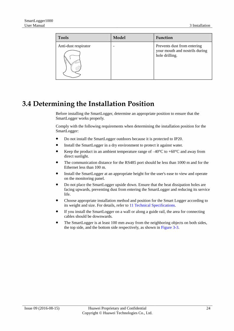
Tools Model Function
Anti-dust respirator
- Prevents dust from entering
your mouth and nostrils during
hole drilling.
3.4 Determining the Installation Position
Before installing the SmartLogger, determine an appropriate position to ensure that the
SmartLogger works properly.
Comply with the following requirements when determining the installation position for the
SmartLogger:
Do not install the SmartLogger outdoors because it is protected to IP20.
Install the SmartLogger in a dry environment to protect it against water.
Keep the product in an ambient temperature range of –40°C to +60°C and away from
direct sunlight.
The communication distance for the RS485 port should be less than 1000 m and for the
Ethernet less than 100 m.
Install the SmartLogger at an appropriate height for the user's ease to view and operate
on the monitoring panel.
Do not place the SmartLogger upside down. Ensure that the heat dissipation holes are
facing upwards, preventing dust from entering the SmartLogger and reducing its service
life.
Choose appropriate installation method and position for the Smart Logger according to
its weight and size. For details, refer to 11 Technical Specifications.
If you install the SmartLogger on a wall or along a guide rail, the area for connecting
cables should be downwards.
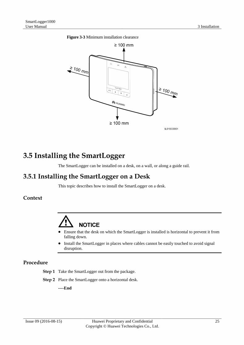
The SmartLogger is at least 100 mm away from the neighboring objects on both sides,
the top side, and the bottom side respectively, as shown in Figure 3-3.
SmartLogger1000
User Manual 3 Installation
Issue 09 (2016-08-15) Huawei Proprietary and Confidential
Copyright © Huawei Technologies Co., Ltd.
25
Figure 3-3 Minimum installation clearance
3.5 Installing the SmartLogger
The SmartLogger can be installed on a desk, on a wall, or along a guide rail.
3.5.1 Installing the SmartLogger on a Desk
This topic describes how to install the SmartLogger on a desk.
Context
Ensure that the desk on which the SmartLogger is installed is horizontal to prevent it from
falling down.
Install the SmartLogger in places where cables cannot be easily touched to avoid signal
disruption.
Procedure
Step 1 Take the SmartLogger out from the package.
Step 2 Place the SmartLogger onto a horizontal desk.
----End
SmartLogger1000
User Manual 3 Installation
Issue 09 (2016-08-15) Huawei Proprietary and Confidential
Copyright © Huawei Technologies Co., Ltd.
26
3.5.2 Mounting the SmartLogger on a Wall
This topic describes how to mount the SmartLogger on a wall.
Context
Install the SmartLogger on a solid and smooth wall to ensure that it can be secured on the
wall.
Before hanging the SmartLogger on the screws, secure the expansion tubes and screws
into the wall.
Procedure
Step 1 Install the expansion tubes and screws.
If you need to use a ladder to install the SmartLogger on a high position, keep balance to
protect yourself from falling down.
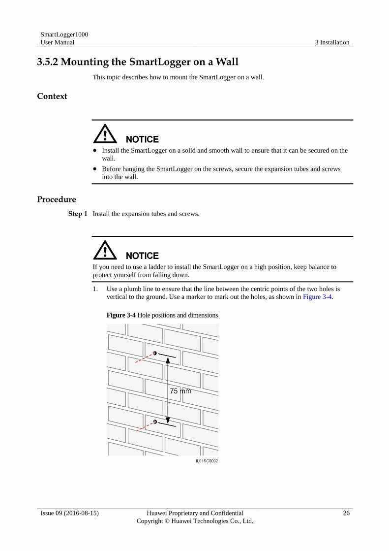
1. Use a plumb line to ensure that the line between the centric points of the two holes is
vertical to the ground. Use a marker to mark out the holes, as shown in Figure 3-4.
Figure 3-4 Hole positions and dimensions
SmartLogger1000
User Manual 3 Installation
Issue 09 (2016-08-15) Huawei Proprietary and Confidential
Copyright © Huawei Technologies Co., Ltd.
27
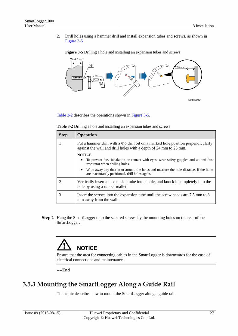
2. Drill holes using a hammer drill and install expansion tubes and screws, as shown in
Figure 3-5.
Figure 3-5 Drilling a hole and installing an expansion tubes and screws
Table 3-2 describes the operations shown in Figure 3-5.
Table 3-2 Drilling a hole and installing an expansion tubes and screws
Step Operation
1 Put a hammer drill with a Ф6 drill bit on a marked hole position perpendicularly
against the wall and drill holes with a depth of 24 mm to 25 mm.
NOTICE
To prevent dust inhalation or contact with eyes, wear safety goggles and an anti-dust
respirator when drilling holes.
Wipe away any dust in or around the holes and measure the hole distance. If the holes
are inaccurately positioned, drill holes again.
2 Vertically insert an expansion tube into a hole, and knock it completely into the
hole by using a rubber mallet.
3 Insert the screws into the expansion tube until the screw heads are 7.5 mm to 8
mm away from the wall.
Step 2 Hang the SmartLogger onto the secured screws by the mounting holes on the rear of the
SmartLogger.
Ensure that the area for connecting cables in the SmartLogger is downwards for the ease of
electrical connections and maintenance.
----End
3.5.3 Mounting the SmartLogger Along a Guide Rail
This topic describes how to mount the SmartLogger along a guide rail.
SmartLogger1000
User Manual 3 Installation
Issue 09 (2016-08-15) Huawei Proprietary and Confidential
Copyright © Huawei Technologies Co., Ltd.
28
Context
The guide rails are not delivered together with the SmartLogger. If you need to mount the
SmartLogger along a guide rail, prepare a 35 mm wide guide rail.
Choose a guide rail with appropriate lengths to ensure that the SmartLogger can be
secured along it.
Secure the guide rail before mounting the SmartLogger.
Procedure
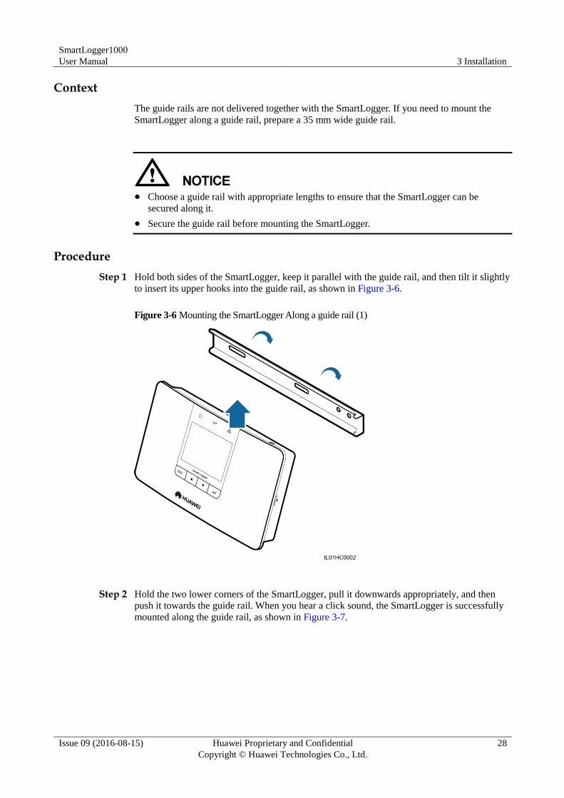
Step 1 Hold both sides of the SmartLogger, keep it parallel with the guide rail, and then tilt it slightly
to insert its upper hooks into the guide rail, as shown in Figure 3-6.
Figure 3-6 Mounting the SmartLogger Along a guide rail (1)
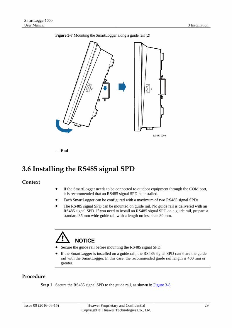
Step 2 Hold the two lower corners of the SmartLogger, pull it downwards appropriately, and then
push it towards the guide rail. When you hear a click sound, the SmartLogger is successfully
mounted along the guide rail, as shown in Figure 3-7.
SmartLogger1000
User Manual 3 Installation
Issue 09 (2016-08-15) Huawei Proprietary and Confidential
Copyright © Huawei Technologies Co., Ltd.
29
Figure 3-7 Mounting the SmartLogger along a guide rail (2)
----End
3.6 Installing the RS485 signal SPD
Context If the SmartLogger needs to be connected to outdoor equipment through the COM port,
it is recommended that an RS485 signal SPD be installed.
Each SmartLogger can be configured with a maximum of two RS485 signal SPDs.
The RS485 signal SPD can be mounted on guide rail. No guide rail is delivered with an
RS485 signal SPD. If you need to install an RS485 signal SPD on a guide rail, prepare a
standard 35 mm wide guide rail with a length no less than 80 mm.
Secure the guide rail before mounting the RS485 signal SPD.
If the SmartLogger is installed on a guide rail, the RS485 signal SPD can share the guide
rail with the SmartLogger. In this case, the recommended guide rail length is 400 mm or
greater.
Procedure
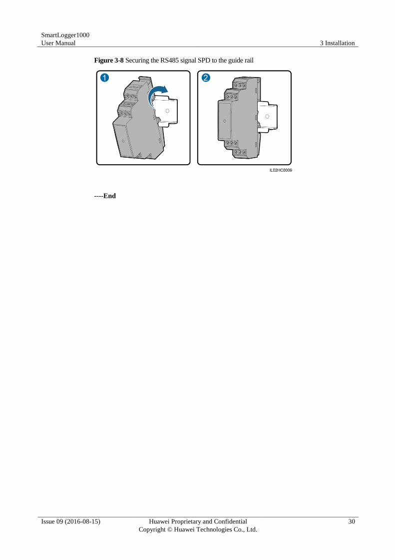
Step 1 Secure the RS485 signal SPD to the guide rail, as shown in Figure 3-8.
SmartLogger1000
User Manual 3 Installation
Issue 09 (2016-08-15) Huawei Proprietary and Confidential
Copyright © Huawei Technologies Co., Ltd.
30
Figure 3-8 Securing the RS485 signal SPD to the guide rail
----End
SmartLogger1000
User Manual 4 Electrical Connections
Issue 09 (2016-08-15) Huawei Proprietary and Confidential
Copyright © Huawei Technologies Co., Ltd.
31
4 Electrical Connections
This topic describes how to connect the SmartLogger to the inverters, environmental
monitoring instrument, and PCs.
Context
Ensure that all cables are connected and secured.
Do not connect a power adapter to the SmartLogger before the cable connections are
complete because the SmartLogger has no startup button.
4.1 Connection Description
Port Description
For the bottom view of the SmartLogger and port description, see Bottom of the Shell in 2.2
Appearance.
Device Connection Description
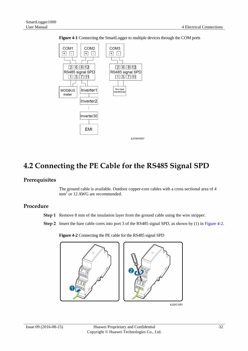
Figure 4-1 shows the recommended method for connecting the SmartLogger to multiple
devices through the COM ports. For details, see 4.3 Connecting the RS485 Signal SPD–4.10
Connecting to a PID.
SmartLogger1000
User Manual 4 Electrical Connections
Issue 09 (2016-08-15) Huawei Proprietary and Confidential
Copyright © Huawei Technologies Co., Ltd.
32
Figure 4-1 Connecting the SmartLogger to multiple devices through the COM ports
4.2 Connecting the PE Cable for the RS485 Signal SPD
Prerequisites
The ground cable is available. Outdoor copper-core cables with a cross sectional area of 4
mm2 or 12 AWG are recommended.
Procedure
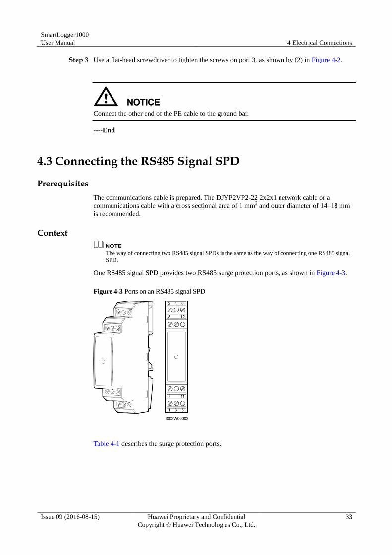
Step 1 Remove 8 mm of the insulation layer from the ground cable using the wire stripper.
Step 2 Insert the bare cable cores into port 3 of the RS485 signal SPD, as shown by (1) in Figure 4-2.
Figure 4-2 Connecting the PE cable for the RS485 signal SPD
SmartLogger1000
User Manual 4 Electrical Connections
Issue 09 (2016-08-15) Huawei Proprietary and Confidential
Copyright © Huawei Technologies Co., Ltd.
33
Step 3 Use a flat-head screwdriver to tighten the screws on port 3, as shown by (2) in Figure 4-2.
Connect the other end of the PE cable to the ground bar.
----End
4.3 Connecting the RS485 Signal SPD
Prerequisites
The communications cable is prepared. The DJYP2VP2-22 2x2x1 network cable or a
communications cable with a cross sectional area of 1 mm2 and outer diameter of 14–18 mm
is recommended.
Context
The way of connecting two RS485 signal SPDs is the same as the way of connecting one RS485 signal
SPD.
One RS485 signal SPD provides two RS485 surge protection ports, as shown in Figure 4-3.
Figure 4-3 Ports on an RS485 signal SPD
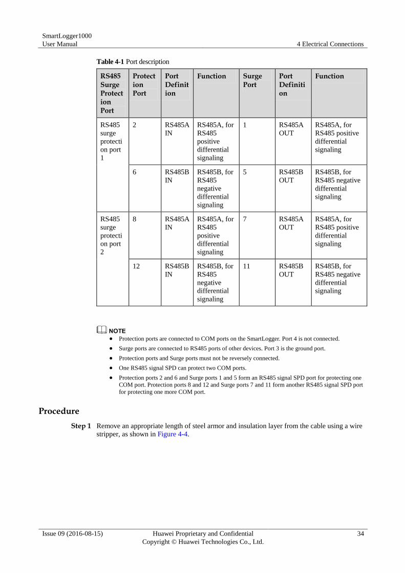
Table 4-1 describes the surge protection ports.
SmartLogger1000
User Manual 4 Electrical Connections
Issue 09 (2016-08-15) Huawei Proprietary and Confidential
Copyright © Huawei Technologies Co., Ltd.
34
Table 4-1 Port description
RS485 Surge Protection Port
Protection Port
Port Definition
Function Surge Port
Port Definition
Function
RS485
surge
protecti
on port
1
2 RS485A
IN
RS485A, for
RS485
positive
differential
signaling
1 RS485A
OUT
RS485A, for
RS485 positive
differential
signaling
6 RS485B
IN
RS485B, for
RS485
negative
differential
signaling
5 RS485B
OUT
RS485B, for
RS485 negative
differential
signaling
RS485
surge
protecti
on port
2
8 RS485A
IN
RS485A, for
RS485
positive
differential
signaling
7 RS485A
OUT
RS485A, for
RS485 positive
differential
signaling
12 RS485B
IN
RS485B, for
RS485
negative
differential
signaling
11 RS485B
OUT
RS485B, for
RS485 negative
differential
signaling
Protection ports are connected to COM ports on the SmartLogger. Port 4 is not connected.
Surge ports are connected to RS485 ports of other devices. Port 3 is the ground port.
Protection ports and Surge ports must not be reversely connected.
One RS485 signal SPD can protect two COM ports.
Protection ports 2 and 6 and Surge ports 1 and 5 form an RS485 signal SPD port for protecting one
COM port. Protection ports 8 and 12 and Surge ports 7 and 11 form another RS485 signal SPD port
for protecting one more COM port.
Procedure
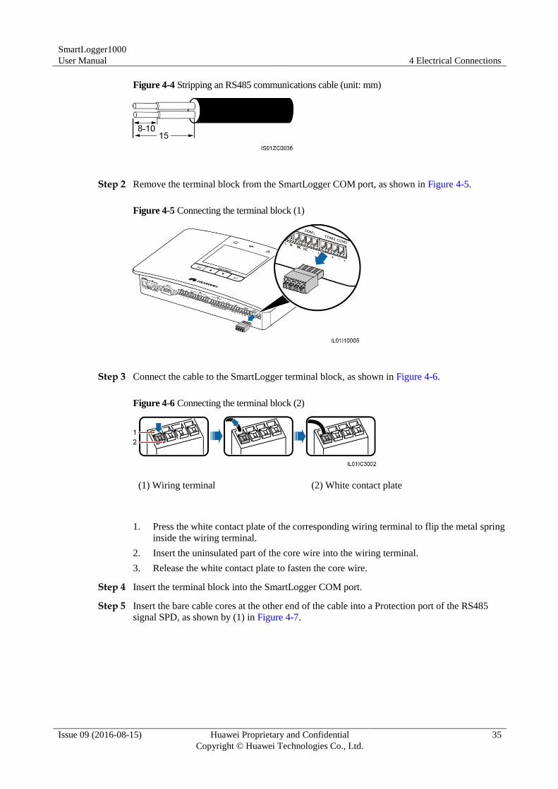
Step 1 Remove an appropriate length of steel armor and insulation layer from the cable using a wire
stripper, as shown in Figure 4-4.
SmartLogger1000
User Manual 4 Electrical Connections
Issue 09 (2016-08-15) Huawei Proprietary and Confidential
Copyright © Huawei Technologies Co., Ltd.
35
Figure 4-4 Stripping an RS485 communications cable (unit: mm)
Step 2 Remove the terminal block from the SmartLogger COM port, as shown in Figure 4-5.
Figure 4-5 Connecting the terminal block (1)
Step 3 Connect the cable to the SmartLogger terminal block, as shown in Figure 4-6.
Figure 4-6 Connecting the terminal block (2)
(1) Wiring terminal (2) White contact plate
1. Press the white contact plate of the corresponding wiring terminal to flip the metal spring
inside the wiring terminal.
2. Insert the uninsulated part of the core wire into the wiring terminal.
3. Release the white contact plate to fasten the core wire.
Step 4 Insert the terminal block into the SmartLogger COM port.
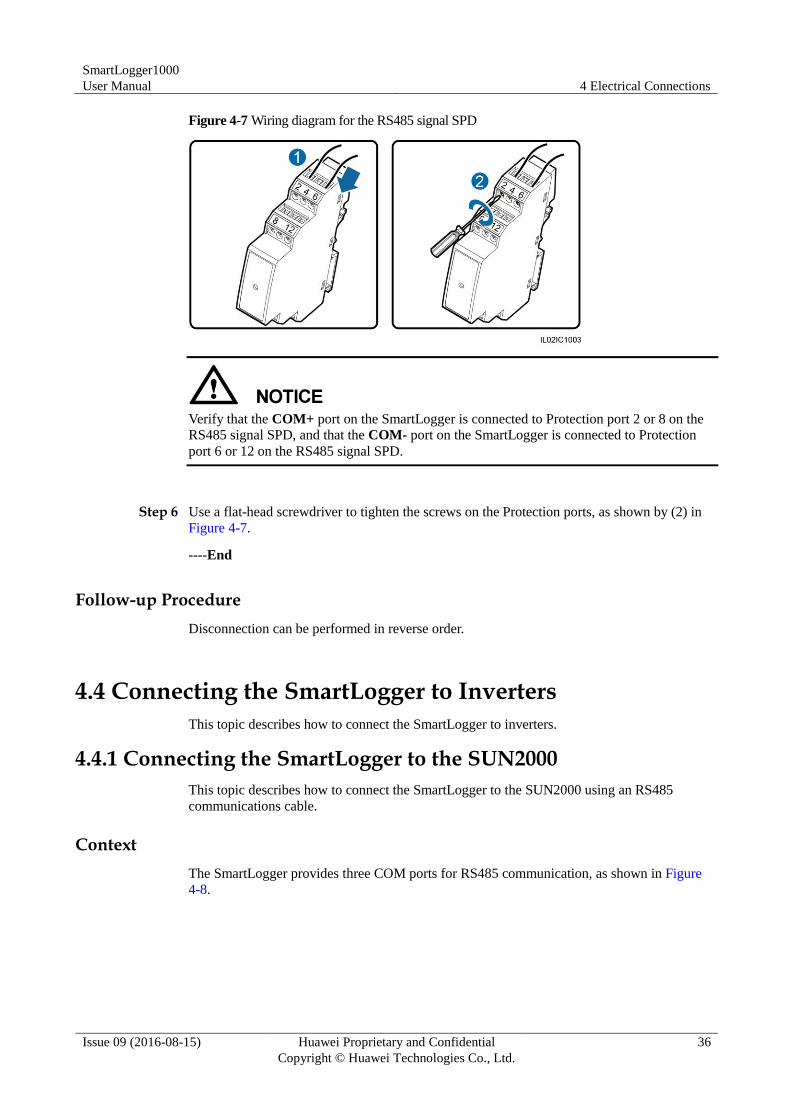
Step 5 Insert the bare cable cores at the other end of the cable into a Protection port of the RS485
signal SPD, as shown by (1) in Figure 4-7.
SmartLogger1000
User Manual 4 Electrical Connections
Issue 09 (2016-08-15) Huawei Proprietary and Confidential
Copyright © Huawei Technologies Co., Ltd.
36
Figure 4-7 Wiring diagram for the RS485 signal SPD
Verify that the COM+ port on the SmartLogger is connected to Protection port 2 or 8 on the
RS485 signal SPD, and that the COM- port on the SmartLogger is connected to Protection
port 6 or 12 on the RS485 signal SPD.
Step 6 Use a flat-head screwdriver to tighten the screws on the Protection ports, as shown by (2) in
Figure 4-7.
----End
Follow-up Procedure
Disconnection can be performed in reverse order.
4.4 Connecting the SmartLogger to Inverters
This topic describes how to connect the SmartLogger to inverters.
4.4.1 Connecting the SmartLogger to the SUN2000
This topic describes how to connect the SmartLogger to the SUN2000 using an RS485
communications cable.
Context
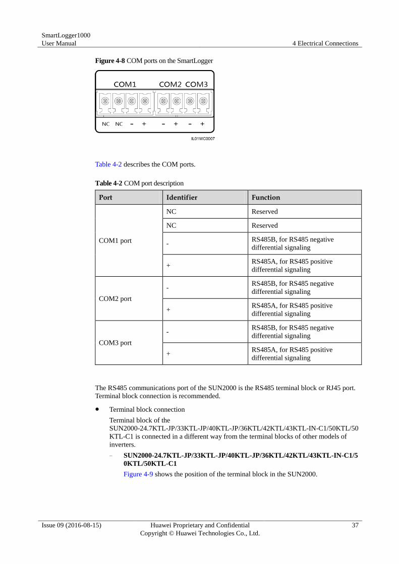
The SmartLogger provides three COM ports for RS485 communication, as shown in Figure
4-8.
SmartLogger1000
User Manual 4 Electrical Connections
Issue 09 (2016-08-15) Huawei Proprietary and Confidential
Copyright © Huawei Technologies Co., Ltd.
37
Figure 4-8 COM ports on the SmartLogger
Table 4-2 describes the COM ports.
Table 4-2 COM port description
Port Identifier Function
COM1 port
NC Reserved
NC Reserved
- RS485B, for RS485 negative
differential signaling
+ RS485A, for RS485 positive
differential signaling
COM2 port
- RS485B, for RS485 negative
differential signaling
+ RS485A, for RS485 positive
differential signaling
COM3 port
- RS485B, for RS485 negative
differential signaling
+ RS485A, for RS485 positive
differential signaling
The RS485 communications port of the SUN2000 is the RS485 terminal block or RJ45 port.
Terminal block connection is recommended.
Terminal block connection
Terminal block of the
SUN2000-24.7KTL-JP/33KTL-JP/40KTL-JP/36KTL/42KTL/43KTL-IN-C1/50KTL/50
KTL-C1 is connected in a different way from the terminal blocks of other models of
inverters.
− SUN2000-24.7KTL-JP/33KTL-JP/40KTL-JP/36KTL/42KTL/43KTL-IN-C1/5
0KTL/50KTL-C1
Figure 4-9 shows the position of the terminal block in the SUN2000.
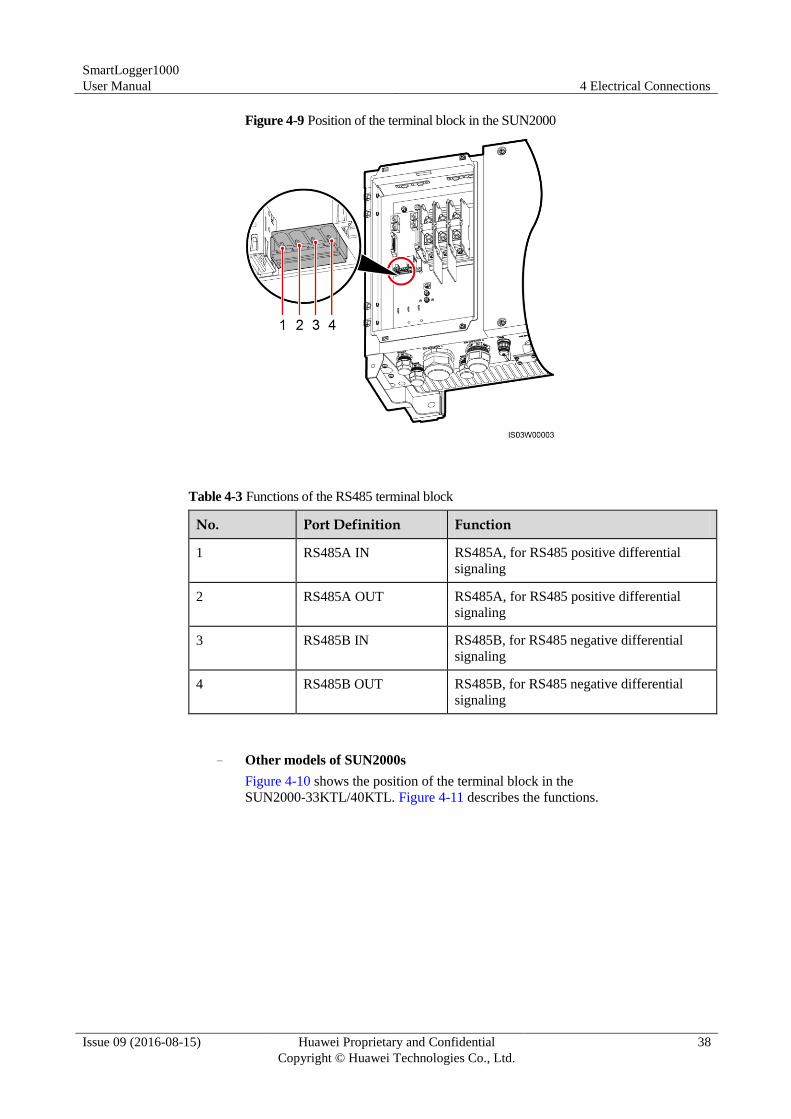
SmartLogger1000
User Manual 4 Electrical Connections
Issue 09 (2016-08-15) Huawei Proprietary and Confidential
Copyright © Huawei Technologies Co., Ltd.
38
Figure 4-9 Position of the terminal block in the SUN2000
Table 4-3 Functions of the RS485 terminal block
No. Port Definition Function
1 RS485A IN RS485A, for RS485 positive differential
signaling
2 RS485A OUT RS485A, for RS485 positive differential
signaling
3 RS485B IN RS485B, for RS485 negative differential
signaling
4 RS485B OUT RS485B, for RS485 negative differential
signaling
− Other models of SUN2000s
Figure 4-10 shows the position of the terminal block in the
SUN2000-33KTL/40KTL. Figure 4-11 describes the functions.
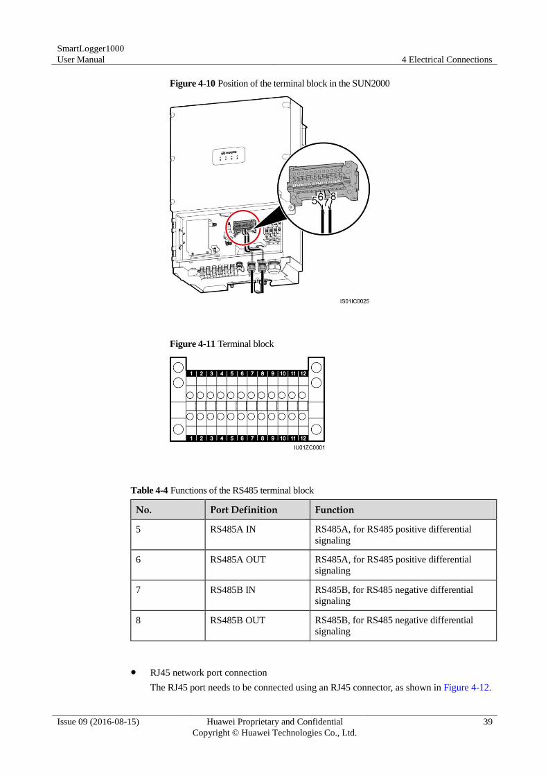
SmartLogger1000
User Manual 4 Electrical Connections
Issue 09 (2016-08-15) Huawei Proprietary and Confidential
Copyright © Huawei Technologies Co., Ltd.
39
Figure 4-10 Position of the terminal block in the SUN2000
Figure 4-11 Terminal block
Table 4-4 Functions of the RS485 terminal block
No. Port Definition Function
5 RS485A IN RS485A, for RS485 positive differential
signaling
6 RS485A OUT RS485A, for RS485 positive differential
signaling
7 RS485B IN RS485B, for RS485 negative differential
signaling
8 RS485B OUT RS485B, for RS485 negative differential
signaling
RJ45 network port connection
The RJ45 port needs to be connected using an RJ45 connector, as shown in Figure 4-12.
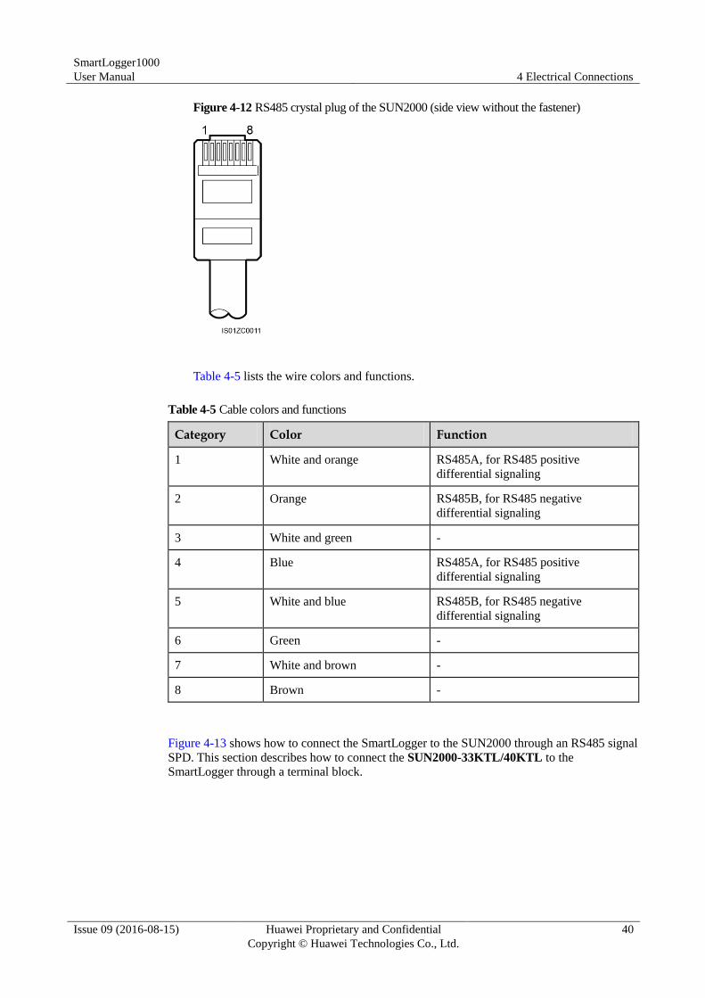
SmartLogger1000
User Manual 4 Electrical Connections
Issue 09 (2016-08-15) Huawei Proprietary and Confidential
Copyright © Huawei Technologies Co., Ltd.
40
Figure 4-12 RS485 crystal plug of the SUN2000 (side view without the fastener)
Table 4-5 lists the wire colors and functions.
Table 4-5 Cable colors and functions
Category Color Function
1 White and orange RS485A, for RS485 positive
differential signaling
2 Orange RS485B, for RS485 negative
differential signaling
3 White and green -
4 Blue RS485A, for RS485 positive
differential signaling
5 White and blue RS485B, for RS485 negative
differential signaling
6 Green -
7 White and brown -
8 Brown -
Figure 4-13 shows how to connect the SmartLogger to the SUN2000 through an RS485 signal
SPD. This section describes how to connect the SUN2000-33KTL/40KTL to the
SmartLogger through a terminal block.
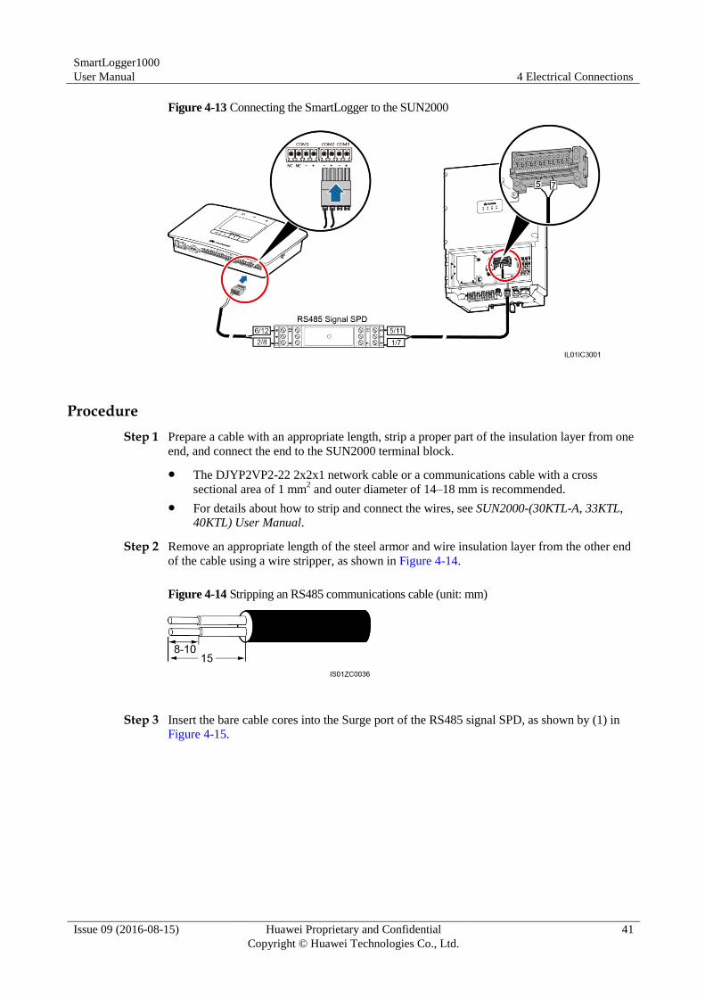
SmartLogger1000
User Manual 4 Electrical Connections
Issue 09 (2016-08-15) Huawei Proprietary and Confidential
Copyright © Huawei Technologies Co., Ltd.
41
Figure 4-13 Connecting the SmartLogger to the SUN2000
Procedure
Step 1 Prepare a cable with an appropriate length, strip a proper part of the insulation layer from one
end, and connect the end to the SUN2000 terminal block.
The DJYP2VP2-22 2x2x1 network cable or a communications cable with a cross
sectional area of 1 mm2 and outer diameter of 14–18 mm is recommended.
For details about how to strip and connect the wires, see SUN2000-(30KTL-A, 33KTL, 40KTL) User Manual.
Step 2 Remove an appropriate length of the steel armor and wire insulation layer from the other end
of the cable using a wire stripper, as shown in Figure 4-14.
Figure 4-14 Stripping an RS485 communications cable (unit: mm)
Step 3 Insert the bare cable cores into the Surge port of the RS485 signal SPD, as shown by (1) in
Figure 4-15.
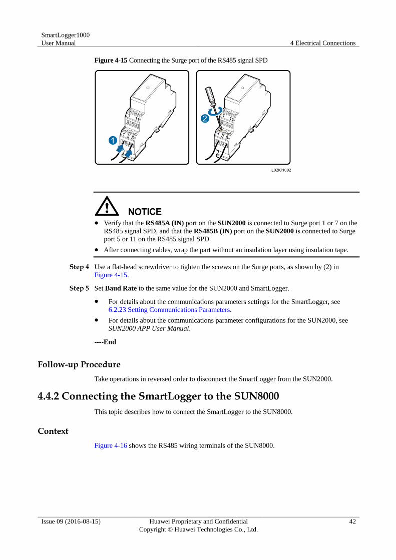
SmartLogger1000
User Manual 4 Electrical Connections
Issue 09 (2016-08-15) Huawei Proprietary and Confidential
Copyright © Huawei Technologies Co., Ltd.
42
Figure 4-15 Connecting the Surge port of the RS485 signal SPD
Verify that the RS485A (IN) port on the SUN2000 is connected to Surge port 1 or 7 on the
RS485 signal SPD, and that the RS485B (IN) port on the SUN2000 is connected to Surge
port 5 or 11 on the RS485 signal SPD.
After connecting cables, wrap the part without an insulation layer using insulation tape.
Step 4 Use a flat-head screwdriver to tighten the screws on the Surge ports, as shown by (2) in
Figure 4-15.
Step 5 Set Baud Rate to the same value for the SUN2000 and SmartLogger.
For details about the communications parameters settings for the SmartLogger, see
6.2.23 Setting Communications Parameters.
For details about the communications parameter configurations for the SUN2000, see
SUN2000 APP User Manual.
----End
Follow-up Procedure
Take operations in reversed order to disconnect the SmartLogger from the SUN2000.
4.4.2 Connecting the SmartLogger to the SUN8000
This topic describes how to connect the SmartLogger to the SUN8000.
Context
Figure 4-16 shows the RS485 wiring terminals of the SUN8000.
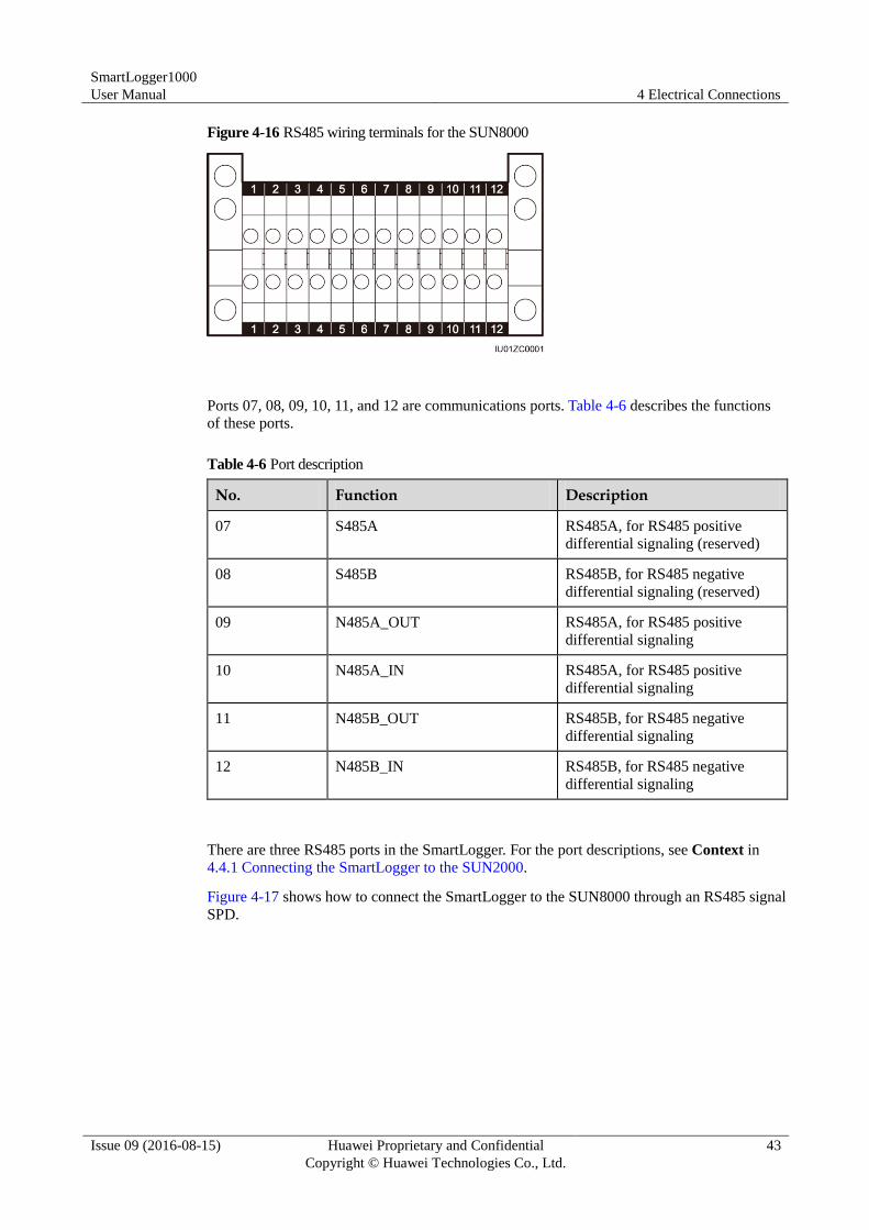
SmartLogger1000
User Manual 4 Electrical Connections
Issue 09 (2016-08-15) Huawei Proprietary and Confidential
Copyright © Huawei Technologies Co., Ltd.
43
Figure 4-16 RS485 wiring terminals for the SUN8000
Ports 07, 08, 09, 10, 11, and 12 are communications ports. Table 4-6 describes the functions
of these ports.
Table 4-6 Port description
No. Function Description
07 S485A RS485A, for RS485 positive
differential signaling (reserved)
08 S485B RS485B, for RS485 negative
differential signaling (reserved)
09 N485A_OUT RS485A, for RS485 positive
differential signaling
10 N485A_IN RS485A, for RS485 positive
differential signaling
11 N485B_OUT RS485B, for RS485 negative
differential signaling
12 N485B_IN RS485B, for RS485 negative
differential signaling
There are three RS485 ports in the SmartLogger. For the port descriptions, see Context in
4.4.1 Connecting the SmartLogger to the SUN2000.
Figure 4-17 shows how to connect the SmartLogger to the SUN8000 through an RS485 signal
SPD.
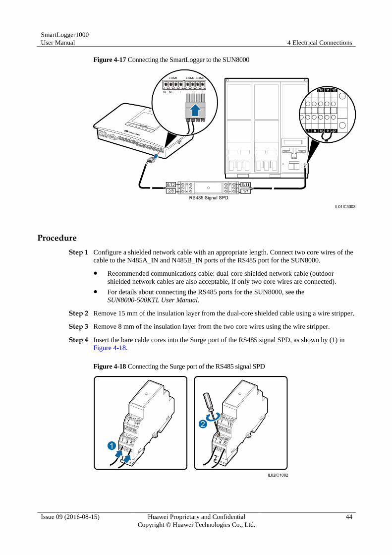
SmartLogger1000
User Manual 4 Electrical Connections
Issue 09 (2016-08-15) Huawei Proprietary and Confidential
Copyright © Huawei Technologies Co., Ltd.
44
Figure 4-17 Connecting the SmartLogger to the SUN8000
Procedure
Step 1 Configure a shielded network cable with an appropriate length. Connect two core wires of the
cable to the N485A_IN and N485B_IN ports of the RS485 port for the SUN8000.
Recommended communications cable: dual-core shielded network cable (outdoor
shielded network cables are also acceptable, if only two core wires are connected).
For details about connecting the RS485 ports for the SUN8000, see the
SUN8000-500KTL User Manual.
Step 2 Remove 15 mm of the insulation layer from the dual-core shielded cable using a wire stripper.
Step 3 Remove 8 mm of the insulation layer from the two core wires using the wire stripper.
Step 4 Insert the bare cable cores into the Surge port of the RS485 signal SPD, as shown by (1) in
Figure 4-18.
Figure 4-18 Connecting the Surge port of the RS485 signal SPD
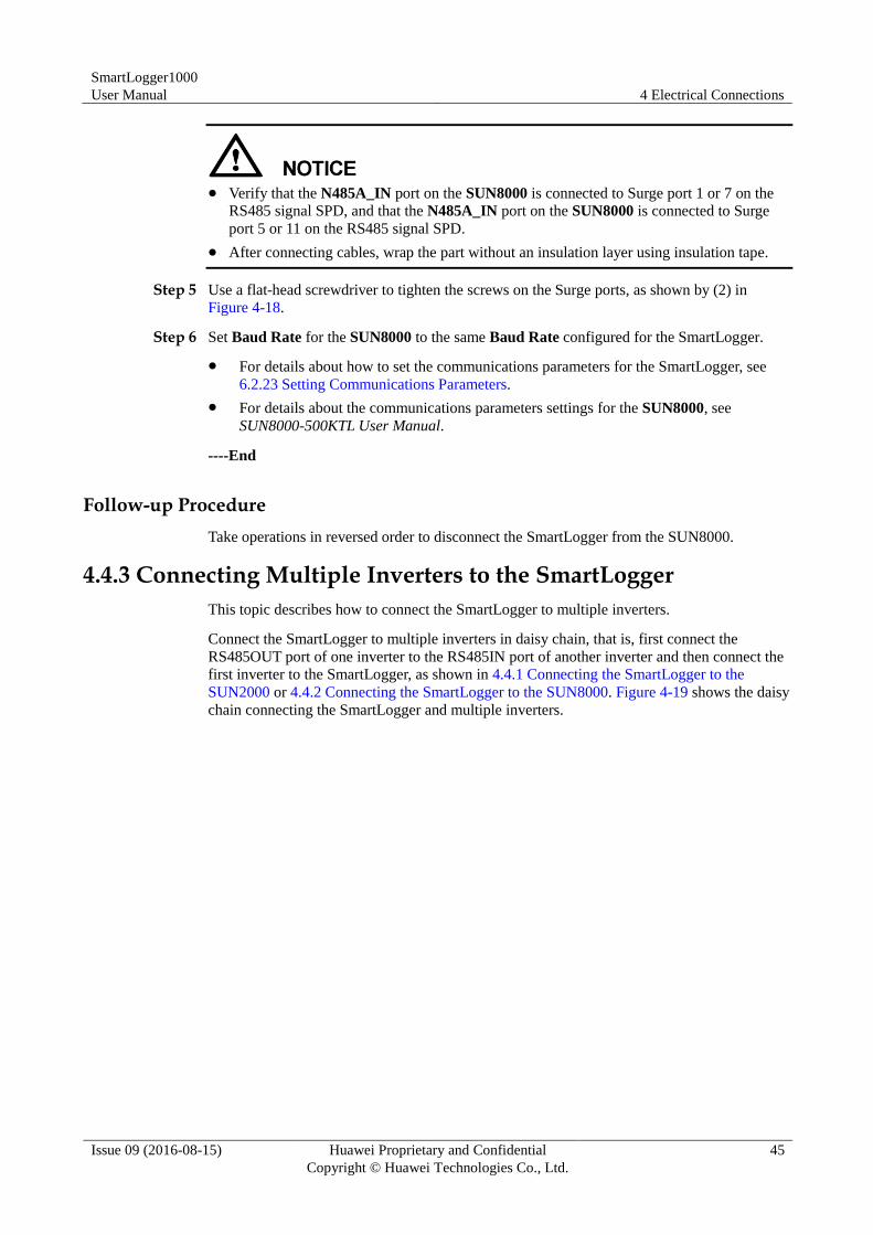
SmartLogger1000
User Manual 4 Electrical Connections
Issue 09 (2016-08-15) Huawei Proprietary and Confidential
Copyright © Huawei Technologies Co., Ltd.
45
Verify that the N485A_IN port on the SUN8000 is connected to Surge port 1 or 7 on the
RS485 signal SPD, and that the N485A_IN port on the SUN8000 is connected to Surge
port 5 or 11 on the RS485 signal SPD.
After connecting cables, wrap the part without an insulation layer using insulation tape.
Step 5 Use a flat-head screwdriver to tighten the screws on the Surge ports, as shown by (2) in
Figure 4-18.
Step 6 Set Baud Rate for the SUN8000 to the same Baud Rate configured for the SmartLogger.
For details about how to set the communications parameters for the SmartLogger, see
6.2.23 Setting Communications Parameters.
For details about the communications parameters settings for the SUN8000, see
SUN8000-500KTL User Manual.
----End
Follow-up Procedure
Take operations in reversed order to disconnect the SmartLogger from the SUN8000.
4.4.3 Connecting Multiple Inverters to the SmartLogger
This topic describes how to connect the SmartLogger to multiple inverters.
Connect the SmartLogger to multiple inverters in daisy chain, that is, first connect the
RS485OUT port of one inverter to the RS485IN port of another inverter and then connect the
first inverter to the SmartLogger, as shown in 4.4.1 Connecting the SmartLogger to the
SUN2000 or 4.4.2 Connecting the SmartLogger to the SUN8000. Figure 4-19 shows the daisy
chain connecting the SmartLogger and multiple inverters.
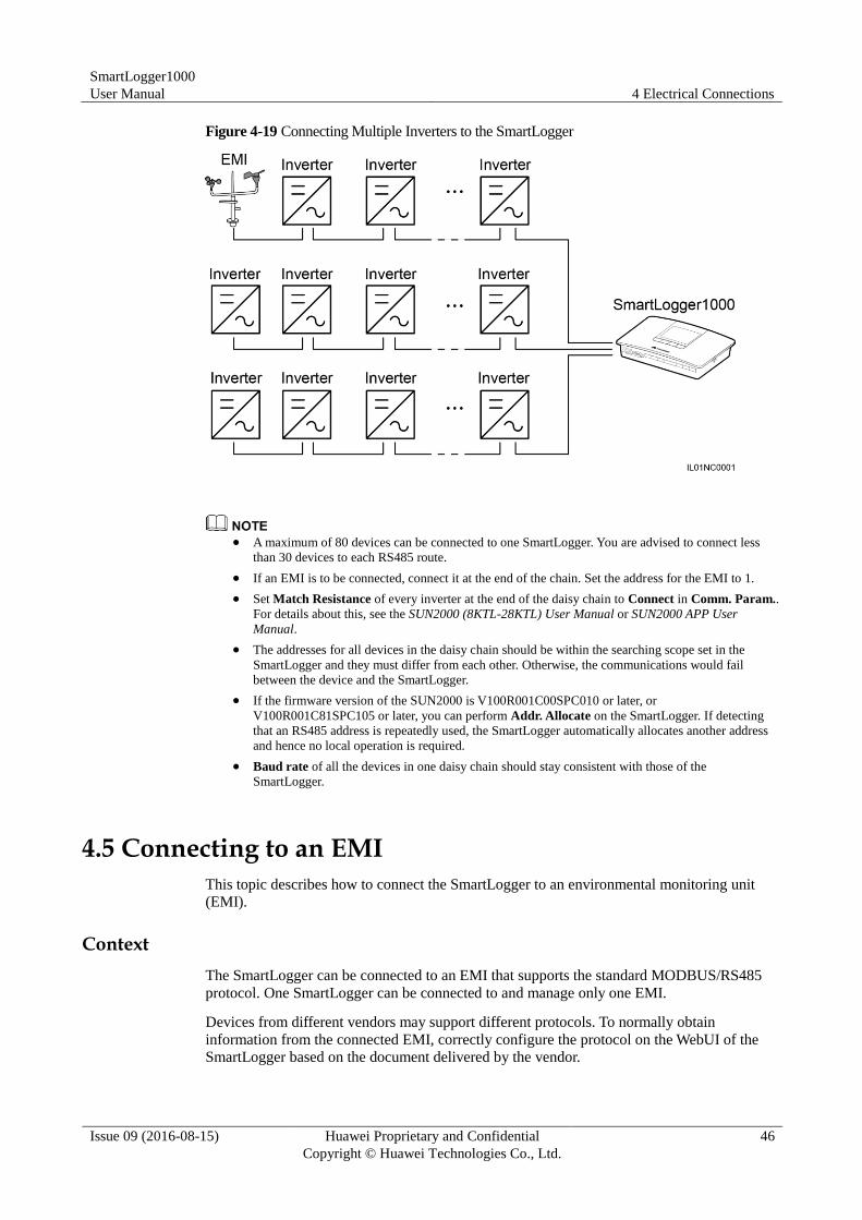
SmartLogger1000
User Manual 4 Electrical Connections
Issue 09 (2016-08-15) Huawei Proprietary and Confidential
Copyright © Huawei Technologies Co., Ltd.
46
Figure 4-19 Connecting Multiple Inverters to the SmartLogger
A maximum of 80 devices can be connected to one SmartLogger. You are advised to connect less
than 30 devices to each RS485 route.
If an EMI is to be connected, connect it at the end of the chain. Set the address for the EMI to 1.
Set Match Resistance of every inverter at the end of the daisy chain to Connect in Comm. Param..
For details about this, see the SUN2000 (8KTL-28KTL) User Manual or SUN2000 APP User
Manual.
The addresses for all devices in the daisy chain should be within the searching scope set in the
SmartLogger and they must differ from each other. Otherwise, the communications would fail
between the device and the SmartLogger.
If the firmware version of the SUN2000 is V100R001C00SPC010 or later, or
V100R001C81SPC105 or later, you can perform Addr. Allocate on the SmartLogger. If detecting
that an RS485 address is repeatedly used, the SmartLogger automatically allocates another address
and hence no local operation is required.
Baud rate of all the devices in one daisy chain should stay consistent with those of the
SmartLogger.
4.5 Connecting to an EMI
This topic describes how to connect the SmartLogger to an environmental monitoring unit
(EMI).
Context
The SmartLogger can be connected to an EMI that supports the standard MODBUS/RS485
protocol. One SmartLogger can be connected to and manage only one EMI.
Devices from different vendors may support different protocols. To normally obtain
information from the connected EMI, correctly configure the protocol on the WebUI of the
SmartLogger based on the document delivered by the vendor.
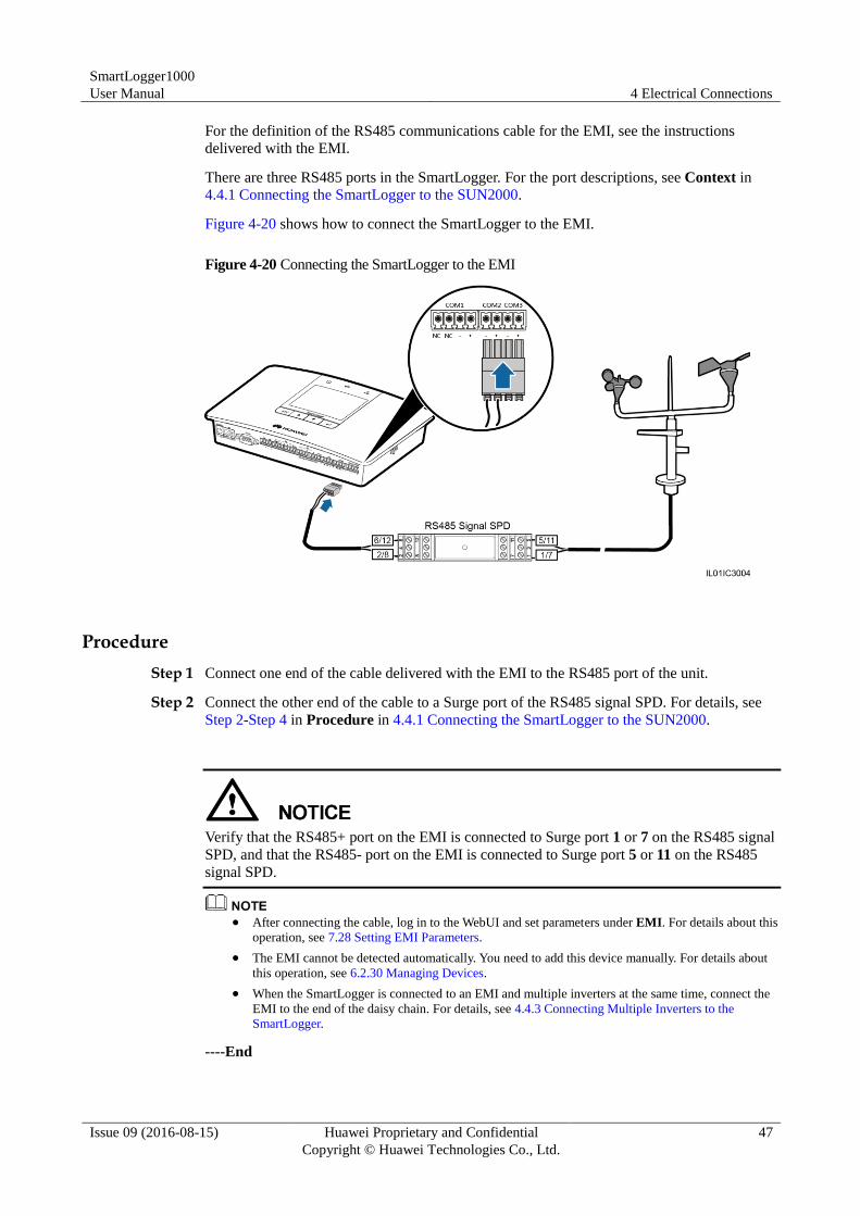
SmartLogger1000
User Manual 4 Electrical Connections
Issue 09 (2016-08-15) Huawei Proprietary and Confidential
Copyright © Huawei Technologies Co., Ltd.
47
For the definition of the RS485 communications cable for the EMI, see the instructions
delivered with the EMI.
There are three RS485 ports in the SmartLogger. For the port descriptions, see Context in
4.4.1 Connecting the SmartLogger to the SUN2000.
Figure 4-20 shows how to connect the SmartLogger to the EMI.
Figure 4-20 Connecting the SmartLogger to the EMI
Procedure
Step 1 Connect one end of the cable delivered with the EMI to the RS485 port of the unit.
Step 2 Connect the other end of the cable to a Surge port of the RS485 signal SPD. For details, see
Step 2-Step 4 in Procedure in 4.4.1 Connecting the SmartLogger to the SUN2000.
Verify that the RS485+ port on the EMI is connected to Surge port 1 or 7 on the RS485 signal
SPD, and that the RS485- port on the EMI is connected to Surge port 5 or 11 on the RS485
signal SPD.
After connecting the cable, log in to the WebUI and set parameters under EMI. For details about this
operation, see 7.28 Setting EMI Parameters.
The EMI cannot be detected automatically. You need to add this device manually. For details about
this operation, see 6.2.30 Managing Devices.
When the SmartLogger is connected to an EMI and multiple inverters at the same time, connect the
EMI to the end of the daisy chain. For details, see 4.4.3 Connecting Multiple Inverters to the
SmartLogger.
----End
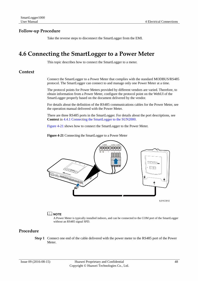
SmartLogger1000
User Manual 4 Electrical Connections
Issue 09 (2016-08-15) Huawei Proprietary and Confidential
Copyright © Huawei Technologies Co., Ltd.
48
Follow-up Procedure
Take the reverse steps to disconnect the SmartLogger from the EMI.
4.6 Connecting the SmartLogger to a Power Meter
This topic describes how to connect the SmartLogger to a meter.
Context
Connect the SmartLogger to a Power Meter that complies with the standard MODBUS/RS485
protocol. The SmartLogger can connect to and manage only one Power Meter at a time.
The protocol points for Power Meters provided by different vendors are varied. Therefore, to
obtain information from a Power Meter, configure the protocol point on the WebUI of the
SmartLogger properly based on the document delivered by the vendor.
For details about the definition of the RS485 communications cables for the Power Meter, see
the operation manual delivered with the Power Meter.
There are three RS485 ports in the SmartLogger. For details about the port descriptions, see
Context in 4.4.1 Connecting the SmartLogger to the SUN2000.
Figure 4-21 shows how to connect the SmartLogger to the Power Meter.
Figure 4-21 Connecting the SmartLogger to a Power Meter
A Power Meter is typically installed indoors, and can be connected to the COM port of the SmartLogger
without an RS485 signal SPD.
Procedure
Step 1 Connect one end of the cable delivered with the power meter to the RS485 port of the Power
Meter.
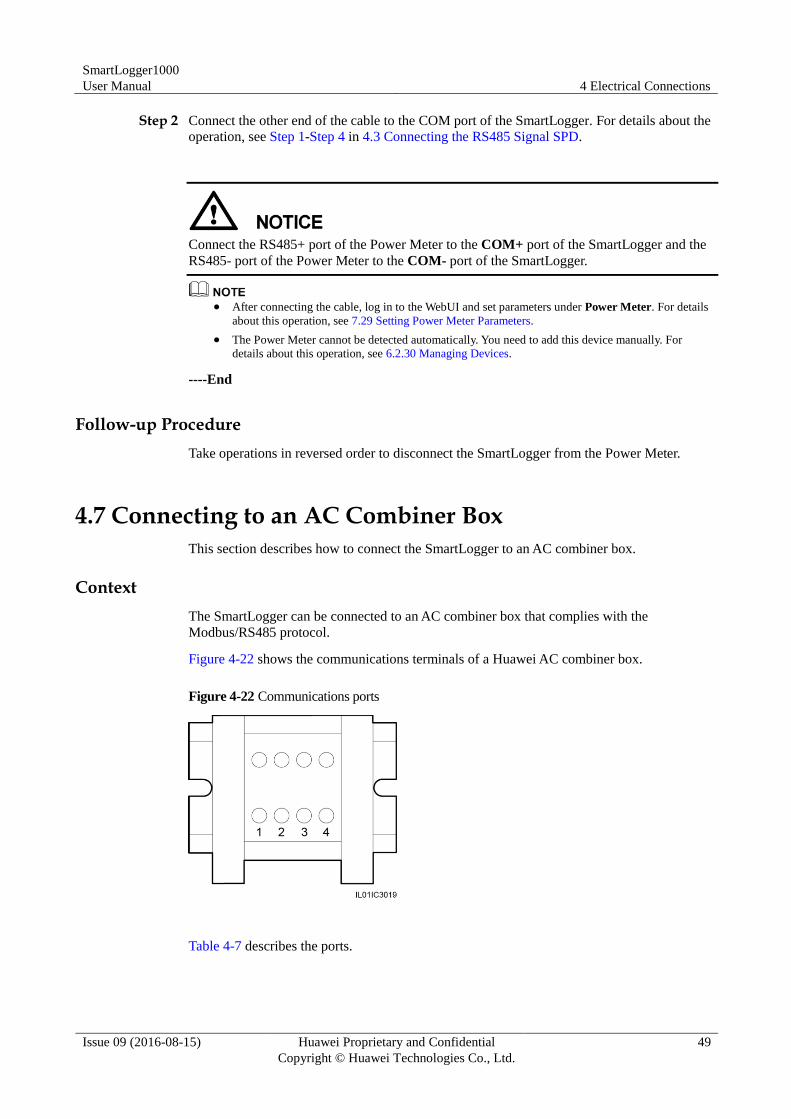
SmartLogger1000
User Manual 4 Electrical Connections
Issue 09 (2016-08-15) Huawei Proprietary and Confidential
Copyright © Huawei Technologies Co., Ltd.
49
Step 2 Connect the other end of the cable to the COM port of the SmartLogger. For details about the
operation, see Step 1-Step 4 in 4.3 Connecting the RS485 Signal SPD.
Connect the RS485+ port of the Power Meter to the COM+ port of the SmartLogger and the
RS485- port of the Power Meter to the COM- port of the SmartLogger.
After connecting the cable, log in to the WebUI and set parameters under Power Meter. For details
about this operation, see 7.29 Setting Power Meter Parameters.
The Power Meter cannot be detected automatically. You need to add this device manually. For
details about this operation, see 6.2.30 Managing Devices.
----End
Follow-up Procedure
Take operations in reversed order to disconnect the SmartLogger from the Power Meter.
4.7 Connecting to an AC Combiner Box
This section describes how to connect the SmartLogger to an AC combiner box.
Context
The SmartLogger can be connected to an AC combiner box that complies with the
Modbus/RS485 protocol.
Figure 4-22 shows the communications terminals of a Huawei AC combiner box.
Figure 4-22 Communications ports
Table 4-7 describes the ports.
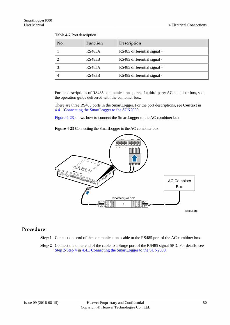
SmartLogger1000
User Manual 4 Electrical Connections
Issue 09 (2016-08-15) Huawei Proprietary and Confidential
Copyright © Huawei Technologies Co., Ltd.
50
Table 4-7 Port description
No. Function Description
1 RS485A RS485 differential signal +
2 RS485B RS485 differential signal -
3 RS485A RS485 differential signal +
4 RS485B RS485 differential signal -
For the descriptions of RS485 communications ports of a third-party AC combiner box, see
the operation guide delivered with the combiner box.
There are three RS485 ports in the SmartLogger. For the port descriptions, see Context in
4.4.1 Connecting the SmartLogger to the SUN2000.
Figure 4-23 shows how to connect the SmartLogger to the AC combiner box.
Figure 4-23 Connecting the SmartLogger to the AC combiner box
Procedure
Step 1 Connect one end of the communications cable to the RS485 port of the AC combiner box.
Step 2 Connect the other end of the cable to a Surge port of the RS485 signal SPD. For details, see
Step 2-Step 4 in 4.4.1 Connecting the SmartLogger to the SUN2000.
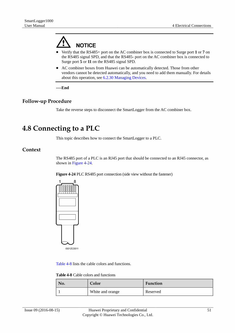
SmartLogger1000
User Manual 4 Electrical Connections
Issue 09 (2016-08-15) Huawei Proprietary and Confidential
Copyright © Huawei Technologies Co., Ltd.
51
Verify that the RS485+ port on the AC combiner box is connected to Surge port 1 or 7 on
the RS485 signal SPD, and that the RS485- port on the AC combiner box is connected to
Surge port 5 or 11 on the RS485 signal SPD.
AC combiner boxes from Huawei can be automatically detected. Those from other
vendors cannot be detected automatically, and you need to add them manually. For details
about this operation, see 6.2.30 Managing Devices.
----End
Follow-up Procedure
Take the reverse steps to disconnect the SmartLogger from the AC combiner box.
4.8 Connecting to a PLC
This topic describes how to connect the SmartLogger to a PLC.
Context
The RS485 port of a PLC is an RJ45 port that should be connected to an RJ45 connector, as
shown in Figure 4-24.
Figure 4-24 PLC RS485 port connection (side view without the fastener)
Table 4-8 lists the cable colors and functions.
Table 4-8 Cable colors and functions
No. Color Function
1 White and orange Reserved
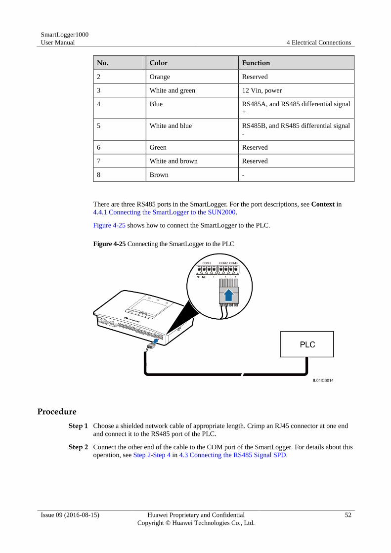
SmartLogger1000
User Manual 4 Electrical Connections
Issue 09 (2016-08-15) Huawei Proprietary and Confidential
Copyright © Huawei Technologies Co., Ltd.
52
No. Color Function
2 Orange Reserved
3 White and green 12 Vin, power
4 Blue RS485A, and RS485 differential signal
+
5 White and blue RS485B, and RS485 differential signal
-
6 Green Reserved
7 White and brown Reserved
8 Brown -
There are three RS485 ports in the SmartLogger. For the port descriptions, see Context in
4.4.1 Connecting the SmartLogger to the SUN2000.
Figure 4-25 shows how to connect the SmartLogger to the PLC.
Figure 4-25 Connecting the SmartLogger to the PLC
Procedure
Step 1 Choose a shielded network cable of appropriate length. Crimp an RJ45 connector at one end
and connect it to the RS485 port of the PLC.
Step 2 Connect the other end of the cable to the COM port of the SmartLogger. For details about this
operation, see Step 2-Step 4 in 4.3 Connecting the RS485 Signal SPD.
SmartLogger1000
User Manual 4 Electrical Connections
Issue 09 (2016-08-15) Huawei Proprietary and Confidential
Copyright © Huawei Technologies Co., Ltd.
53
Connect the RS485+ port of the PLC to the COM+ port of the SmartLogger and connect
the RS485- port of the PLC to the COM- port of the SmartLogger.
The PLC cannot be detected automatically. You need to add this device manually. For
details about this operation, see 6.2.30 Managing Devices.
The Huawei PLC supports auto-negotiation of baud rate 9600 bps/115200 bps. If the PLC
networking is used, you are advised to set Baud rate to 115200bps for the RS485 ports of
the SmartLogger to achieve better communication performance.
----End
Follow-up Procedure
Take the reverse steps to disconnect the SmartLogger from the PLC.
4.9 Connecting an Ethernet Network Cable
Context
The SmartLogger can be connected to an Ethernet switch, router, or POE module. It can also
be connected to the Ethernet electrical port of a PC directly or through a hub. Select the
connection device based on the actual networking scenario.
Procedure
Step 1 Connect one end of the delivered network cable to the Ethernet electrical port of a device.
If the delivered cable is too short, pay attention to the following when preparing a cable:
Select CAT 5E or a higher-class shielded network cable.
It is suggested that the cable length is less than or equal to 100 meters.
Step 2 Connect the other end of the network cable to the FE port of the SmartLogger, as shown in
Figure 4-26.
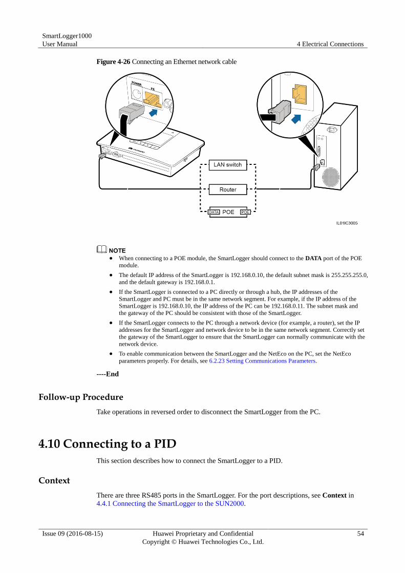
SmartLogger1000
User Manual 4 Electrical Connections
Issue 09 (2016-08-15) Huawei Proprietary and Confidential
Copyright © Huawei Technologies Co., Ltd.
54
Figure 4-26 Connecting an Ethernet network cable
When connecting to a POE module, the SmartLogger should connect to the DATA port of the POE
module.
The default IP address of the SmartLogger is 192.168.0.10, the default subnet mask is 255.255.255.0,
and the default gateway is 192.168.0.1.
If the SmartLogger is connected to a PC directly or through a hub, the IP addresses of the
SmartLogger and PC must be in the same network segment. For example, if the IP address of the
SmartLogger is 192.168.0.10, the IP address of the PC can be 192.168.0.11. The subnet mask and
the gateway of the PC should be consistent with those of the SmartLogger.
If the SmartLogger connects to the PC through a network device (for example, a router), set the IP
addresses for the SmartLogger and network device to be in the same network segment. Correctly set
the gateway of the SmartLogger to ensure that the SmartLogger can normally communicate with the
network device.
To enable communication between the SmartLogger and the NetEco on the PC, set the NetEco
parameters properly. For details, see 6.2.23 Setting Communications Parameters.
----End
Follow-up Procedure
Take operations in reversed order to disconnect the SmartLogger from the PC.
4.10 Connecting to a PID
This section describes how to connect the SmartLogger to a PID.
Context
There are three RS485 ports in the SmartLogger. For the port descriptions, see Context in
4.4.1 Connecting the SmartLogger to the SUN2000.
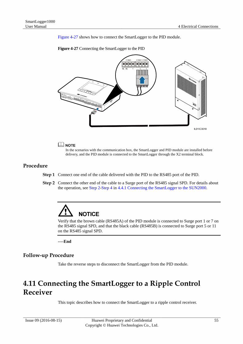
SmartLogger1000
User Manual 4 Electrical Connections
Issue 09 (2016-08-15) Huawei Proprietary and Confidential
Copyright © Huawei Technologies Co., Ltd.
55
Figure 4-27 shows how to connect the SmartLogger to the PID module.
Figure 4-27 Connecting the SmartLogger to the PID
In the scenarios with the communication box, the SmartLogger and PID module are installed before
delivery, and the PID module is connected to the SmartLogger through the X2 terminal block.
Procedure
Step 1 Connect one end of the cable delivered with the PID to the RS485 port of the PID.
Step 2 Connect the other end of the cable to a Surge port of the RS485 signal SPD. For details about
the operation, see Step 2-Step 4 in 4.4.1 Connecting the SmartLogger to the SUN2000.
Verify that the brown cable (RS485A) of the PID module is connected to Surge port 1 or 7 on
the RS485 signal SPD, and that the black cable (RS485B) is connected to Surge port 5 or 11
on the RS485 signal SPD.
----End
Follow-up Procedure
Take the reverse steps to disconnect the SmartLogger from the PID module.
4.11 Connecting the SmartLogger to a Ripple Control Receiver
This topic describes how to connect the SmartLogger to a ripple control receiver.
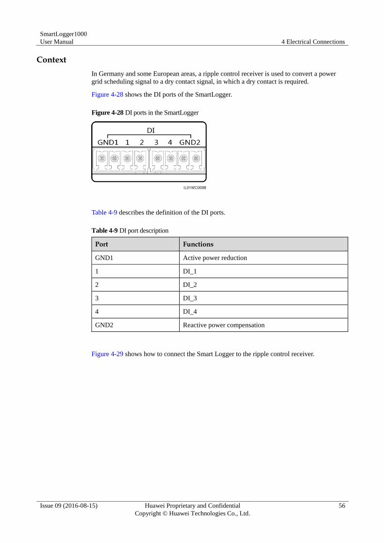
SmartLogger1000
User Manual 4 Electrical Connections
Issue 09 (2016-08-15) Huawei Proprietary and Confidential
Copyright © Huawei Technologies Co., Ltd.
56
Context
In Germany and some European areas, a ripple control receiver is used to convert a power
grid scheduling signal to a dry contact signal, in which a dry contact is required.
Figure 4-28 shows the DI ports of the SmartLogger.
Figure 4-28 DI ports in the SmartLogger
Table 4-9 describes the definition of the DI ports.
Table 4-9 DI port description
Port Functions
GND1 Active power reduction
1 DI_1
2 DI_2
3 DI_3
4 DI_4
GND2 Reactive power compensation
Figure 4-29 shows how to connect the Smart Logger to the ripple control receiver.
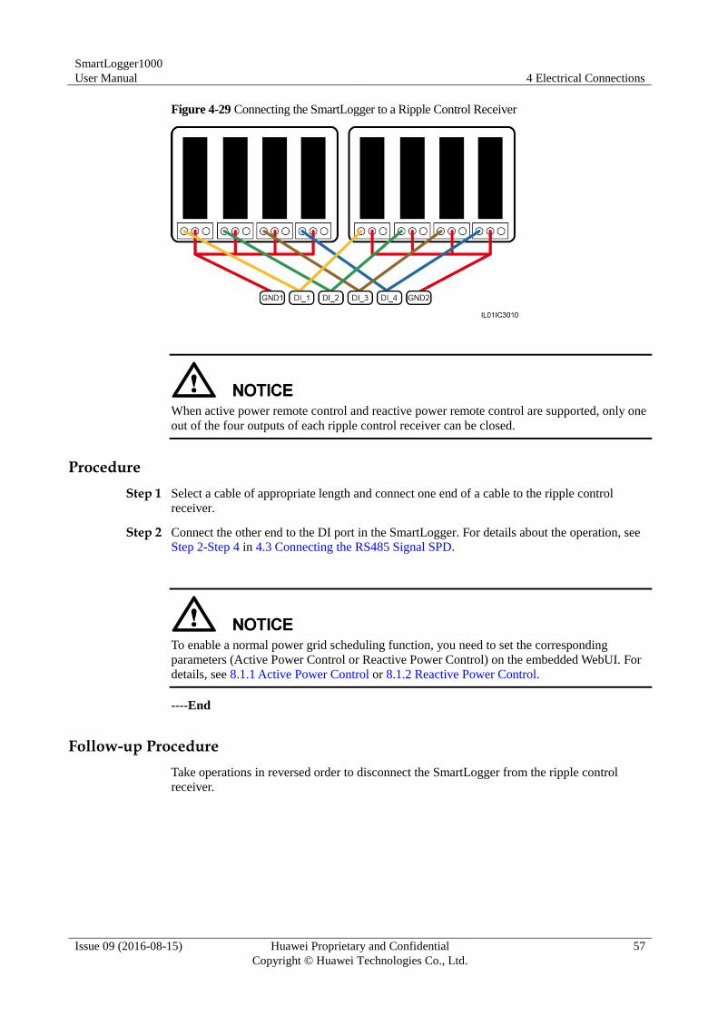
SmartLogger1000
User Manual 4 Electrical Connections
Issue 09 (2016-08-15) Huawei Proprietary and Confidential
Copyright © Huawei Technologies Co., Ltd.
57
Figure 4-29 Connecting the SmartLogger to a Ripple Control Receiver
When active power remote control and reactive power remote control are supported, only one
out of the four outputs of each ripple control receiver can be closed.
Procedure
Step 1 Select a cable of appropriate length and connect one end of a cable to the ripple control
receiver.
Step 2 Connect the other end to the DI port in the SmartLogger. For details about the operation, see
Step 2-Step 4 in 4.3 Connecting the RS485 Signal SPD.
To enable a normal power grid scheduling function, you need to set the corresponding
parameters (Active Power Control or Reactive Power Control) on the embedded WebUI. For
details, see 8.1.1 Active Power Control or 8.1.2 Reactive Power Control.
----End
Follow-up Procedure
Take operations in reversed order to disconnect the SmartLogger from the ripple control
receiver.
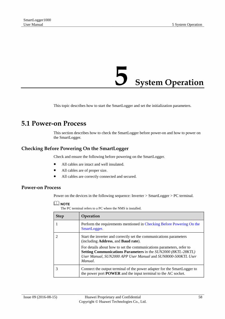
SmartLogger1000
User Manual 5 System Operation
Issue 09 (2016-08-15) Huawei Proprietary and Confidential
Copyright © Huawei Technologies Co., Ltd.
58
5 System Operation
This topic describes how to start the SmartLogger and set the initialization parameters.
5.1 Power-on Process
This section describes how to check the SmartLogger before power-on and how to power on
the SmartLogger.
Checking Before Powering On the SmartLogger
Check and ensure the following before powering on the SmartLogger.
All cables are intact and well insulated.
All cables are of proper size.
All cables are correctly connected and secured.
Power-on Process
Power on the devices in the following sequence: Inverter > SmartLogger > PC terminal.
The PC terminal refers to a PC where the NMS is installed.
Step Operation
1 Perform the requirements mentioned in Checking Before Powering On the
SmartLogger.
2 Start the inverter and correctly set the communications parameters
(including Address, and Baud rate).
For details about how to set the communications parameters, refer to
Setting Communications Parameters in the SUN2000 (8KTL-28KTL)
User Manual, SUN2000 APP User Manual and SUN8000-500KTL User Manual.
3 Connect the output terminal of the power adapter for the SmartLogger to
the power port POWER and the input terminal to the AC socket.
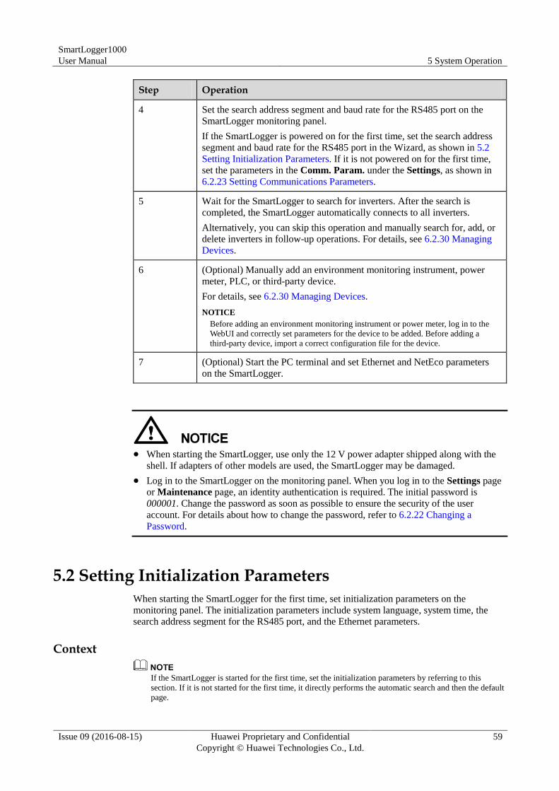
SmartLogger1000
User Manual 5 System Operation
Issue 09 (2016-08-15) Huawei Proprietary and Confidential
Copyright © Huawei Technologies Co., Ltd.
59
Step Operation
4 Set the search address segment and baud rate for the RS485 port on the
SmartLogger monitoring panel.
If the SmartLogger is powered on for the first time, set the search address
segment and baud rate for the RS485 port in the Wizard, as shown in 5.2
Setting Initialization Parameters. If it is not powered on for the first time,
set the parameters in the Comm. Param. under the Settings, as shown in
6.2.23 Setting Communications Parameters.
5 Wait for the SmartLogger to search for inverters. After the search is
completed, the SmartLogger automatically connects to all inverters.
Alternatively, you can skip this operation and manually search for, add, or
delete inverters in follow-up operations. For details, see 6.2.30 Managing
Devices.
6 (Optional) Manually add an environment monitoring instrument, power
meter, PLC, or third-party device.
For details, see 6.2.30 Managing Devices.
NOTICE
Before adding an environment monitoring instrument or power meter, log in to the
WebUI and correctly set parameters for the device to be added. Before adding a
third-party device, import a correct configuration file for the device.
7 (Optional) Start the PC terminal and set Ethernet and NetEco parameters
on the SmartLogger.
When starting the SmartLogger, use only the 12 V power adapter shipped along with the
shell. If adapters of other models are used, the SmartLogger may be damaged.
Log in to the SmartLogger on the monitoring panel. When you log in to the Settings page
or Maintenance page, an identity authentication is required. The initial password is
000001. Change the password as soon as possible to ensure the security of the user
account. For details about how to change the password, refer to 6.2.22 Changing a
Password.
5.2 Setting Initialization Parameters
When starting the SmartLogger for the first time, set initialization parameters on the
monitoring panel. The initialization parameters include system language, system time, the
search address segment for the RS485 port, and the Ethernet parameters.
Context
If the SmartLogger is started for the first time, set the initialization parameters by referring to this
section. If it is not started for the first time, it directly performs the automatic search and then the default
page.
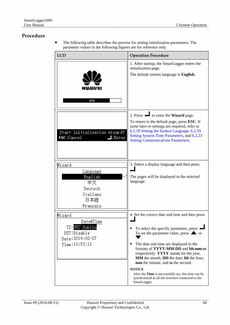
SmartLogger1000
User Manual 5 System Operation
Issue 09 (2016-08-15) Huawei Proprietary and Confidential
Copyright © Huawei Technologies Co., Ltd.
60
Procedure The following table describes the process for setting initialization parameters. The
parameter values in the following figures are for reference only.
LCD Operation Procedure
1. After startup, the SmartLogger enters the
initialization page.
The default system language is English.
2. Press to enter the Wizard page.
To return to the default page, press ESC. If
some later re-settings are required, refer to
6.2.18 Setting the System Language, 6.2.19
Setting System Time Parameters, and 6.2.23
Setting Communications Parameters.
3. Select a display language and then press
.
The pages will be displayed in the selected
language.
4. Set the correct date and time and then press
.
To select the specific parameter, press .
To set the parameter value, press or
.
The date and time are displayed in the
formats of YYYY-MM-DD and hh:mm:ss
respectively. YYYY stands for the year,
MM the month, DD the date, hh the hour,
mm the minute, and ss the second.
NOTICE
After the Time is successfully set, this time can be
synchronized in all the inverters connected to the
SmartLogger.
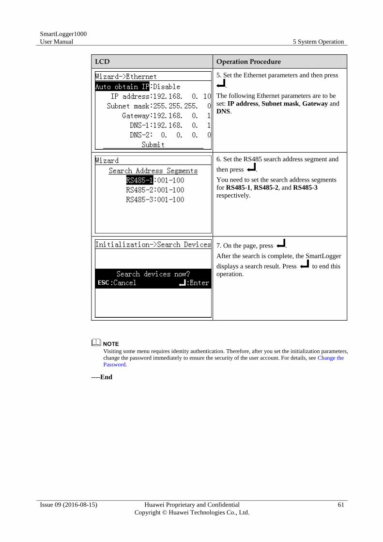
SmartLogger1000
User Manual 5 System Operation
Issue 09 (2016-08-15) Huawei Proprietary and Confidential
Copyright © Huawei Technologies Co., Ltd.
61
LCD Operation Procedure
5. Set the Ethernet parameters and then press
.
The following Ethernet parameters are to be
set: IP address, Subnet mask, Gateway and
DNS.
6. Set the RS485 search address segment and
then press .
You need to set the search address segments
for RS485-1, RS485-2, and RS485-3
respectively.
7. On the page, press .
After the search is complete, the SmartLogger
displays a search result. Press to end this
operation.
Visiting some menu requires identity authentication. Therefore, after you set the initialization parameters,
change the password immediately to ensure the security of the user account. For details, see Change the
Password.
----End
SmartLogger1000
User Manual 6 User Interface
Issue 09 (2016-08-15) Huawei Proprietary and Confidential
Copyright © Huawei Technologies Co., Ltd.
62
6 User Interface
This topic describes the monitoring menu and operations.
Context
Figures provided in this chapter correspond to the SUN2000 V100R001C95SPC108 version.
The data in the figures provided in this document are for reference only.
6.1 Monitoring Menu Hierarchy
This topic describes the monitoring menu hierarchy, which allows you to perform operations
conveniently.
Figure 6-1 shows the monitoring menu hierarchy.
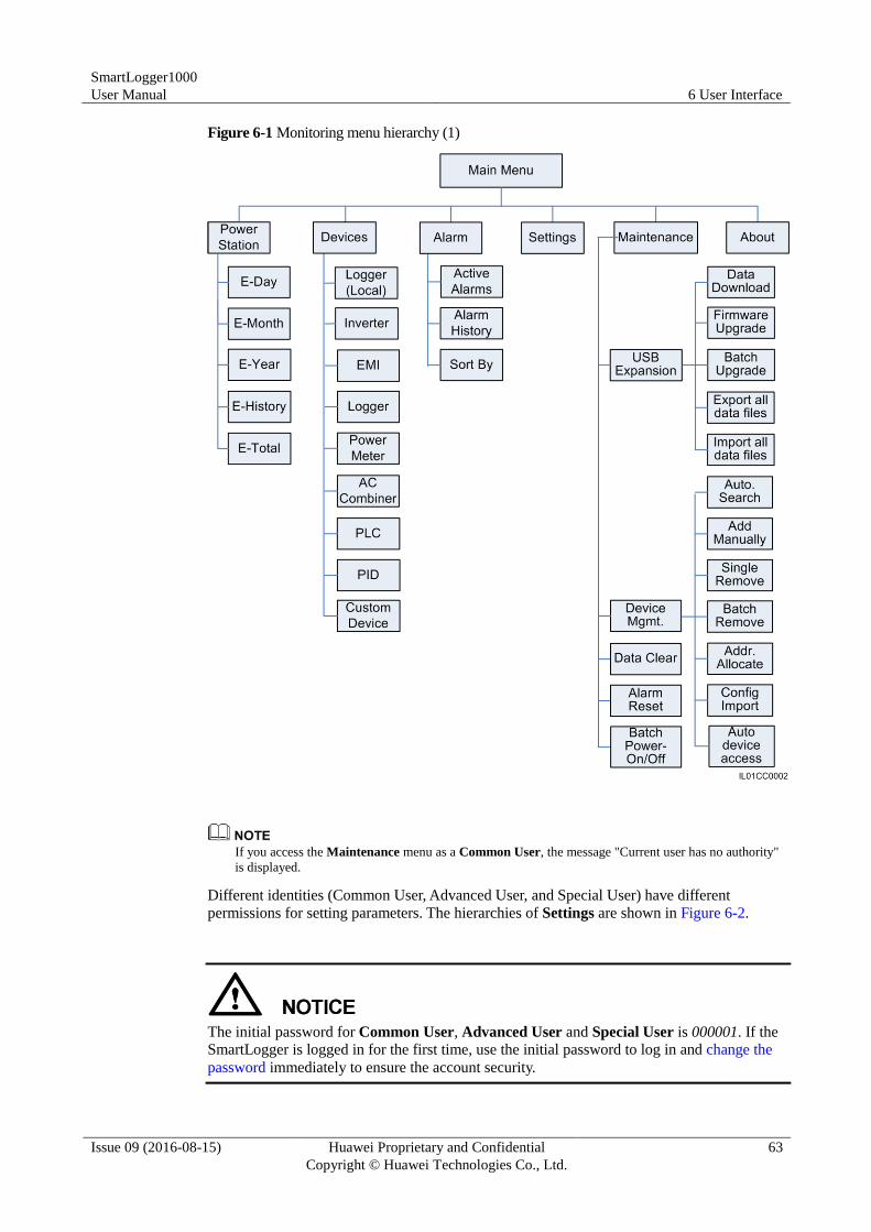
SmartLogger1000
User Manual 6 User Interface
Issue 09 (2016-08-15) Huawei Proprietary and Confidential
Copyright © Huawei Technologies Co., Ltd.
63
Figure 6-1 Monitoring menu hierarchy (1)
If you access the Maintenance menu as a Common User, the message "Current user has no authority"
is displayed.
Different identities (Common User, Advanced User, and Special User) have different
permissions for setting parameters. The hierarchies of Settings are shown in Figure 6-2.
The initial password for Common User, Advanced User and Special User is 000001. If the
SmartLogger is logged in for the first time, use the initial password to log in and change the
password immediately to ensure the account security.
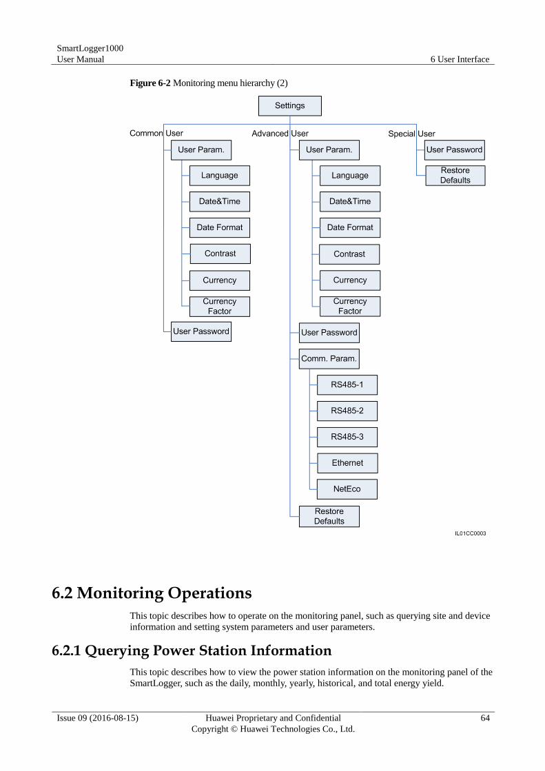
SmartLogger1000
User Manual 6 User Interface
Issue 09 (2016-08-15) Huawei Proprietary and Confidential
Copyright © Huawei Technologies Co., Ltd.
64
Figure 6-2 Monitoring menu hierarchy (2)
6.2 Monitoring Operations
This topic describes how to operate on the monitoring panel, such as querying site and device
information and setting system parameters and user parameters.
6.2.1 Querying Power Station Information
This topic describes how to view the power station information on the monitoring panel of the
SmartLogger, such as the daily, monthly, yearly, historical, and total energy yield.
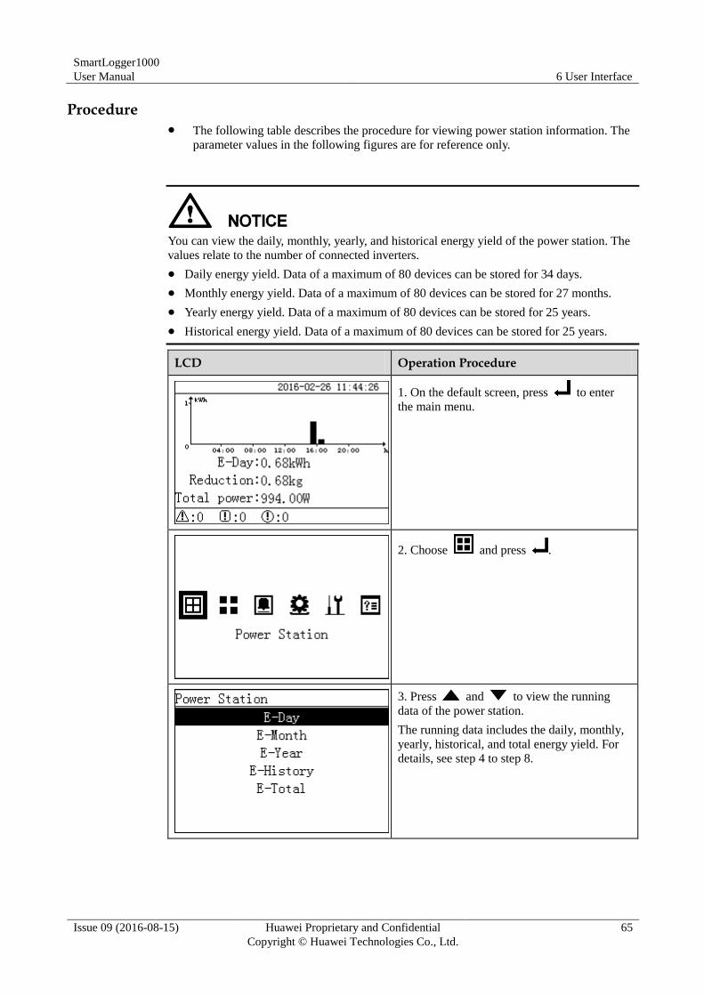
SmartLogger1000
User Manual 6 User Interface
Issue 09 (2016-08-15) Huawei Proprietary and Confidential
Copyright © Huawei Technologies Co., Ltd.
65
Procedure The following table describes the procedure for viewing power station information. The
parameter values in the following figures are for reference only.
You can view the daily, monthly, yearly, and historical energy yield of the power station. The
values relate to the number of connected inverters.
Daily energy yield. Data of a maximum of 80 devices can be stored for 34 days.
Monthly energy yield. Data of a maximum of 80 devices can be stored for 27 months.
Yearly energy yield. Data of a maximum of 80 devices can be stored for 25 years.
Historical energy yield. Data of a maximum of 80 devices can be stored for 25 years.
LCD Operation Procedure
1. On the default screen, press to enter
the main menu.
2. Choose and press .
3. Press and to view the running
data of the power station.
The running data includes the daily, monthly,
yearly, historical, and total energy yield. For
details, see step 4 to step 8.
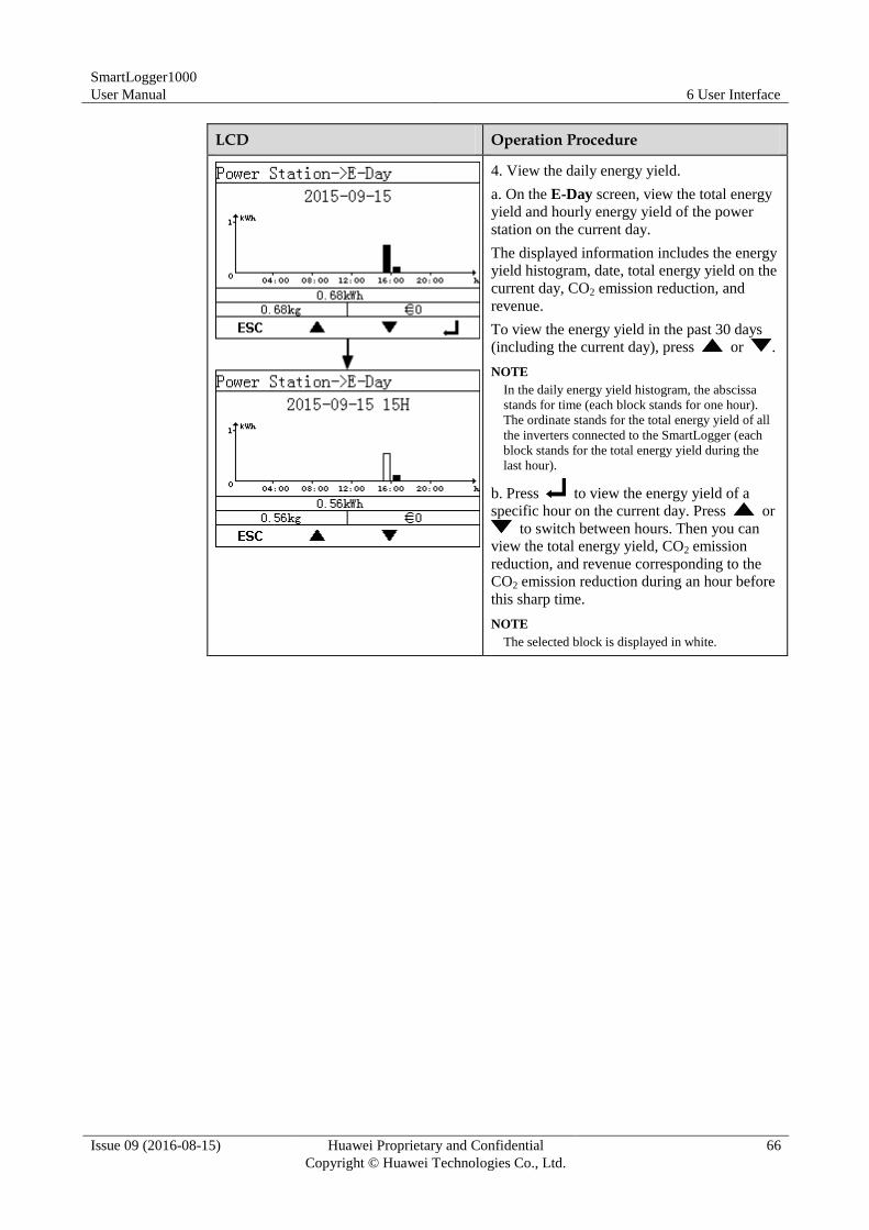
SmartLogger1000
User Manual 6 User Interface
Issue 09 (2016-08-15) Huawei Proprietary and Confidential
Copyright © Huawei Technologies Co., Ltd.
66
LCD Operation Procedure
4. View the daily energy yield.
a. On the E-Day screen, view the total energy
yield and hourly energy yield of the power
station on the current day.
The displayed information includes the energy
yield histogram, date, total energy yield on the
current day, CO2 emission reduction, and
revenue.
To view the energy yield in the past 30 days
(including the current day), press or .
NOTE
In the daily energy yield histogram, the abscissa
stands for time (each block stands for one hour).
The ordinate stands for the total energy yield of all
the inverters connected to the SmartLogger (each
block stands for the total energy yield during the
last hour).
b. Press to view the energy yield of a
specific hour on the current day. Press or
to switch between hours. Then you can
view the total energy yield, CO2 emission
reduction, and revenue corresponding to the
CO2 emission reduction during an hour before
this sharp time.
NOTE
The selected block is displayed in white.
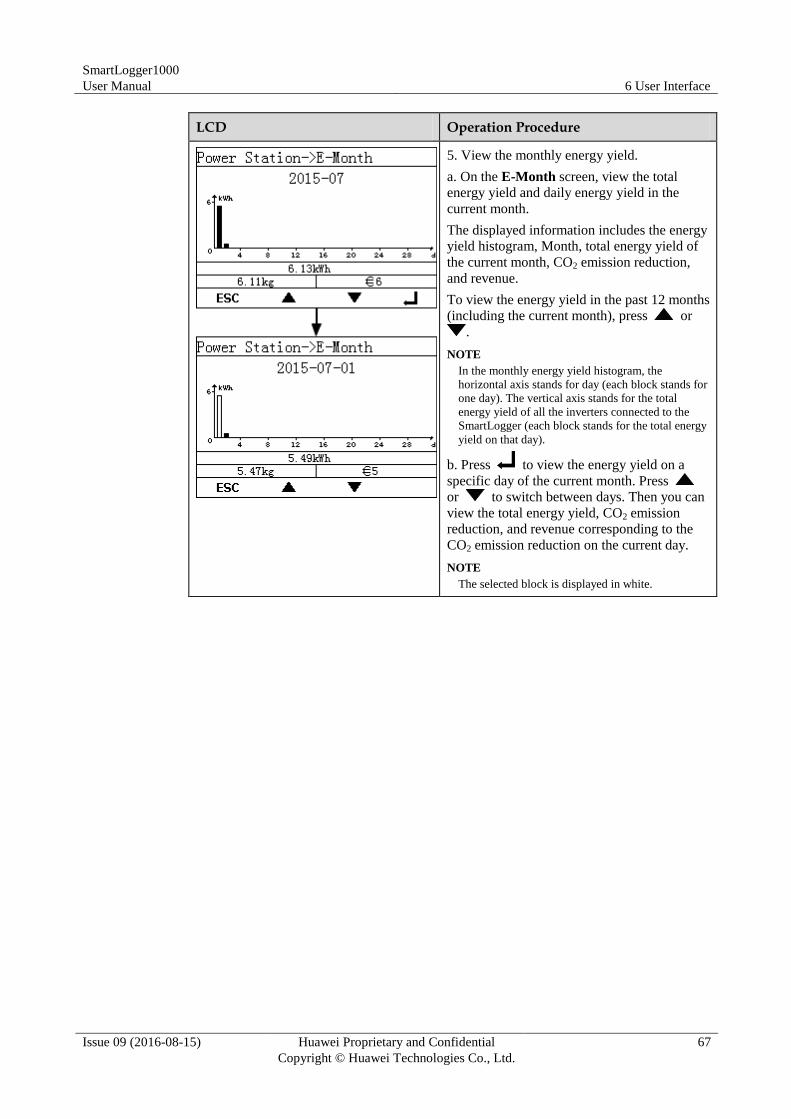
SmartLogger1000
User Manual 6 User Interface
Issue 09 (2016-08-15) Huawei Proprietary and Confidential
Copyright © Huawei Technologies Co., Ltd.
67
LCD Operation Procedure
5. View the monthly energy yield.
a. On the E-Month screen, view the total
energy yield and daily energy yield in the
current month.
The displayed information includes the energy
yield histogram, Month, total energy yield of
the current month, CO2 emission reduction,
and revenue.
To view the energy yield in the past 12 months
(including the current month), press or
.
NOTE
In the monthly energy yield histogram, the
horizontal axis stands for day (each block stands for
one day). The vertical axis stands for the total
energy yield of all the inverters connected to the
SmartLogger (each block stands for the total energy
yield on that day).
b. Press to view the energy yield on a
specific day of the current month. Press
or to switch between days. Then you can
view the total energy yield, CO2 emission
reduction, and revenue corresponding to the
CO2 emission reduction on the current day.
NOTE
The selected block is displayed in white.
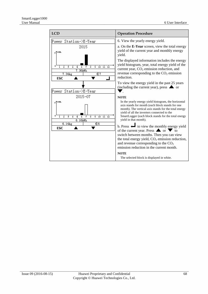
SmartLogger1000
User Manual 6 User Interface
Issue 09 (2016-08-15) Huawei Proprietary and Confidential
Copyright © Huawei Technologies Co., Ltd.
68
LCD Operation Procedure
6. View the yearly energy yield.
a. On the E-Year screen, view the total energy
yield of the current year and monthly energy
yield.
The displayed information includes the energy
yield histogram, year, total energy yield of the
current year, CO2 emission reduction, and
revenue corresponding to the CO2 emission
reduction.
To view the energy yield in the past 25 years
(including the current year), press or
.
NOTE
In the yearly energy yield histogram, the horizontal
axis stands for month (each block stands for one
month). The vertical axis stands for the total energy
yield of all the inverters connected to the
SmartLogger (each block stands for the total energy
yield in that month).
b. Press to view the monthly energy yield
of the current year. Press or to
switch between months. Then you can view
the total energy yield, CO2 emission reduction,
and revenue corresponding to the CO2
emission reduction in the current month.
NOTE
The selected block is displayed in white.
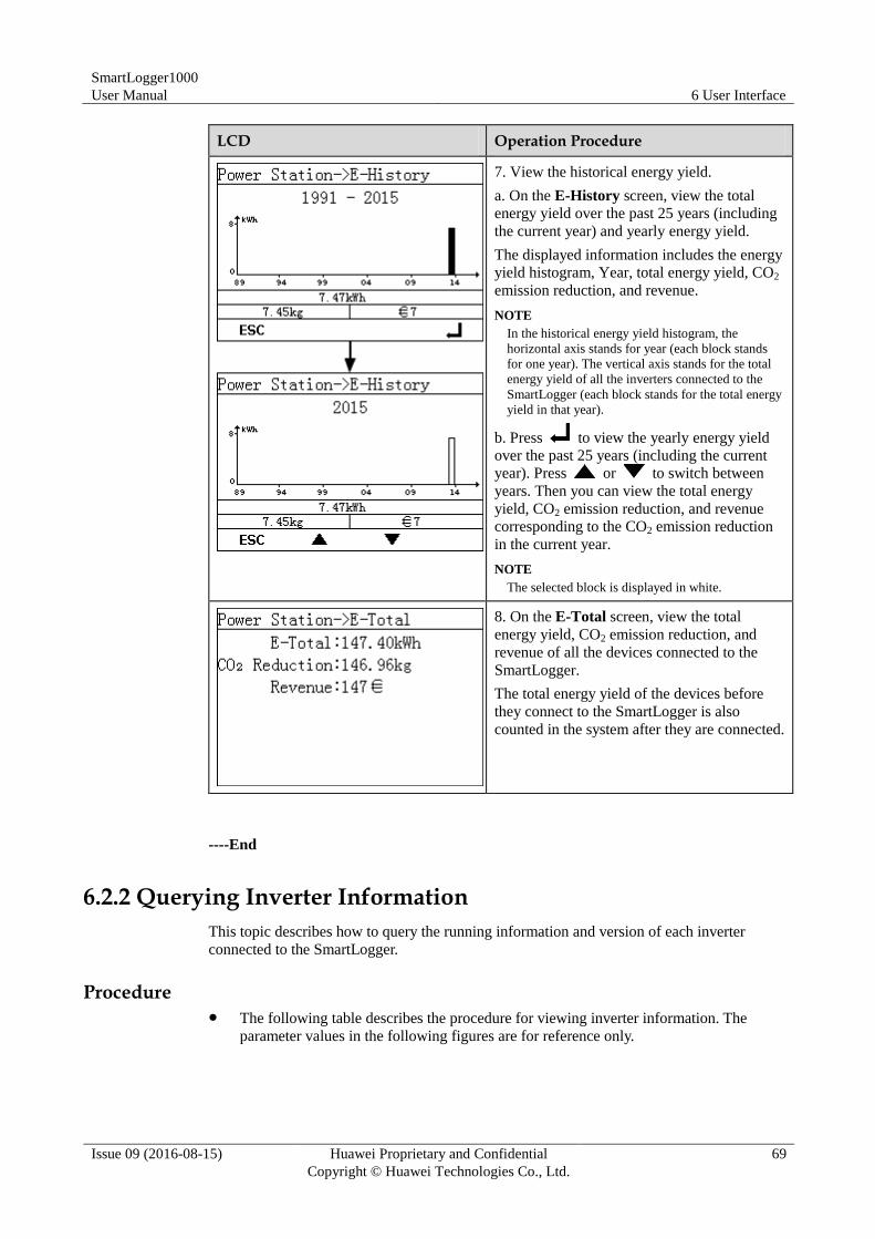
SmartLogger1000
User Manual 6 User Interface
Issue 09 (2016-08-15) Huawei Proprietary and Confidential
Copyright © Huawei Technologies Co., Ltd.
69
LCD Operation Procedure
7. View the historical energy yield.
a. On the E-History screen, view the total
energy yield over the past 25 years (including
the current year) and yearly energy yield.
The displayed information includes the energy
yield histogram, Year, total energy yield, CO2
emission reduction, and revenue.
NOTE
In the historical energy yield histogram, the
horizontal axis stands for year (each block stands
for one year). The vertical axis stands for the total
energy yield of all the inverters connected to the
SmartLogger (each block stands for the total energy
yield in that year).
b. Press to view the yearly energy yield
over the past 25 years (including the current
year). Press or to switch between
years. Then you can view the total energy
yield, CO2 emission reduction, and revenue
corresponding to the CO2 emission reduction
in the current year.
NOTE
The selected block is displayed in white.
8. On the E-Total screen, view the total
energy yield, CO2 emission reduction, and
revenue of all the devices connected to the
SmartLogger.
The total energy yield of the devices before
they connect to the SmartLogger is also
counted in the system after they are connected.
----End
6.2.2 Querying Inverter Information
This topic describes how to query the running information and version of each inverter
connected to the SmartLogger.
Procedure The following table describes the procedure for viewing inverter information. The
parameter values in the following figures are for reference only.
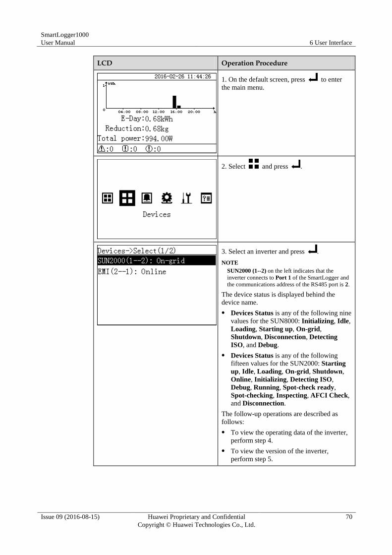
SmartLogger1000
User Manual 6 User Interface
Issue 09 (2016-08-15) Huawei Proprietary and Confidential
Copyright © Huawei Technologies Co., Ltd.
70
LCD Operation Procedure
1. On the default screen, press to enter
the main menu.
2. Select and press .
3. Select an inverter and press .
NOTE
SUN2000 (1--2) on the left indicates that the
inverter connects to Port 1 of the SmartLogger and
the communications address of the RS485 port is 2.
The device status is displayed behind the
device name.
Devices Status is any of the following nine
values for the SUN8000: Initializing, Idle,
Loading, Starting up, On-grid,
Shutdown, Disconnection, Detecting
ISO, and Debug.
Devices Status is any of the following
fifteen values for the SUN2000: Starting
up, Idle, Loading, On-grid, Shutdown,
Online, Initializing, Detecting ISO,
Debug, Running, Spot-check ready,
Spot-checking, Inspecting, AFCI Check,
and Disconnection.
The follow-up operations are described as
follows:
To view the operating data of the inverter,
perform step 4.
To view the version of the inverter,
perform step 5.
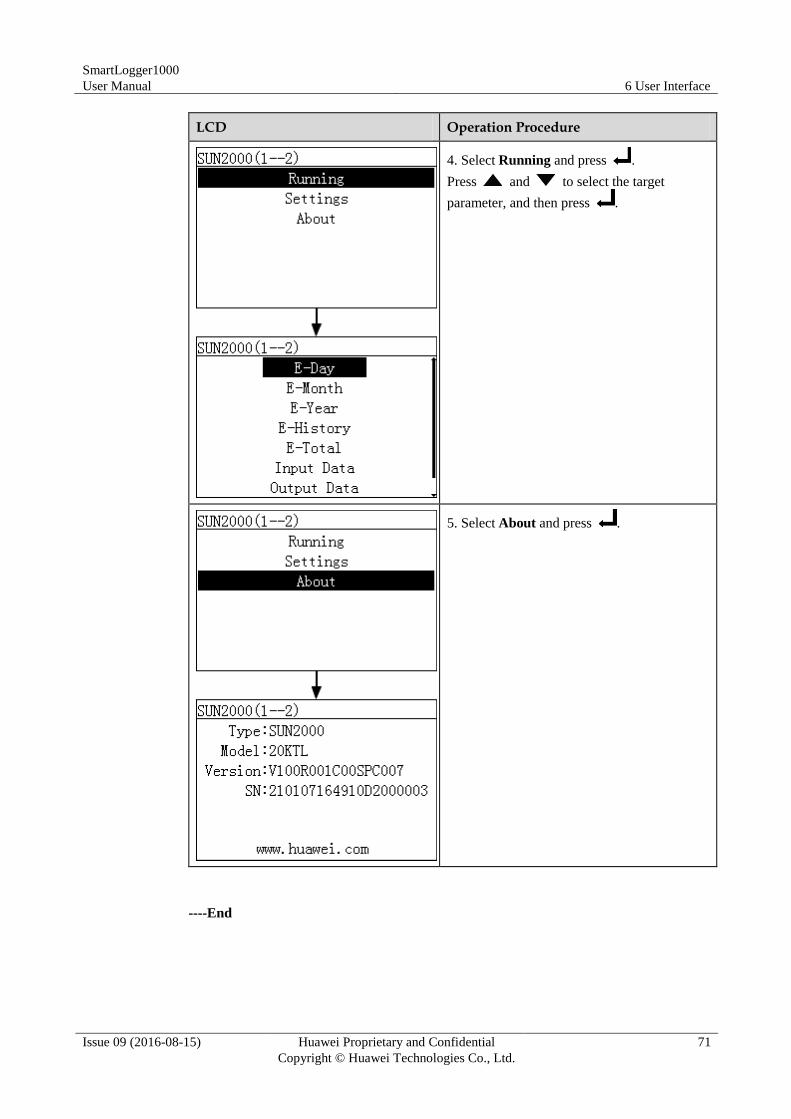
SmartLogger1000
User Manual 6 User Interface
Issue 09 (2016-08-15) Huawei Proprietary and Confidential
Copyright © Huawei Technologies Co., Ltd.
71
LCD Operation Procedure
4. Select Running and press .
Press and to select the target
parameter, and then press .
5. Select About and press .
----End
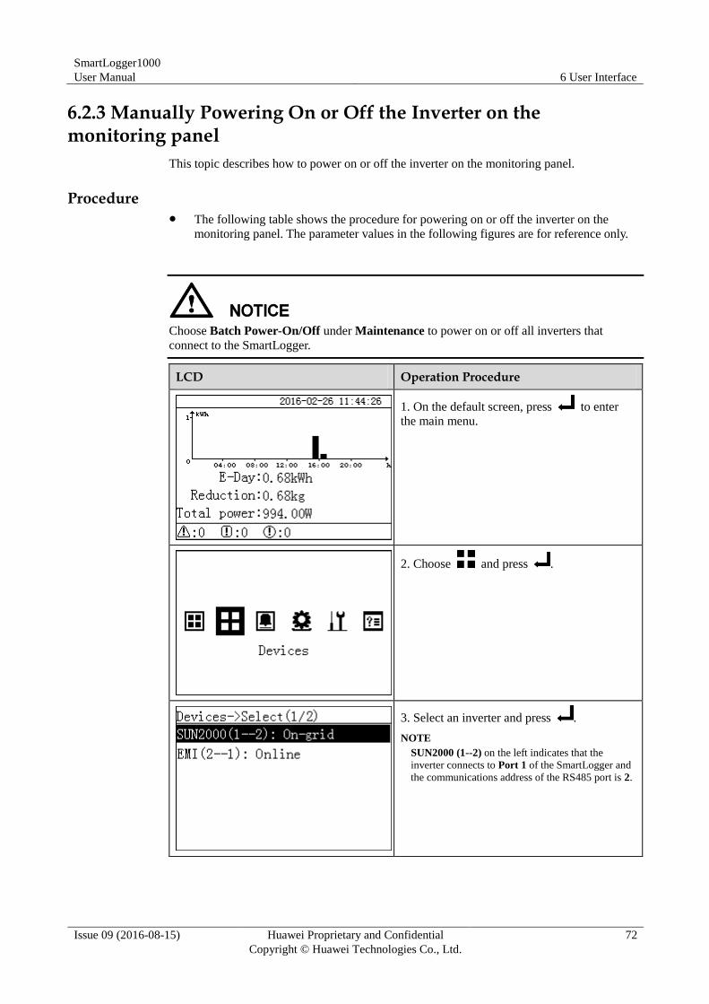
SmartLogger1000
User Manual 6 User Interface
Issue 09 (2016-08-15) Huawei Proprietary and Confidential
Copyright © Huawei Technologies Co., Ltd.
72
6.2.3 Manually Powering On or Off the Inverter on the monitoring panel
This topic describes how to power on or off the inverter on the monitoring panel.
Procedure The following table shows the procedure for powering on or off the inverter on the
monitoring panel. The parameter values in the following figures are for reference only.
Choose Batch Power-On/Off under Maintenance to power on or off all inverters that
connect to the SmartLogger.
LCD Operation Procedure
1. On the default screen, press to enter
the main menu.
2. Choose and press .
3. Select an inverter and press .
NOTE
SUN2000 (1--2) on the left indicates that the
inverter connects to Port 1 of the SmartLogger and
the communications address of the RS485 port is 2.
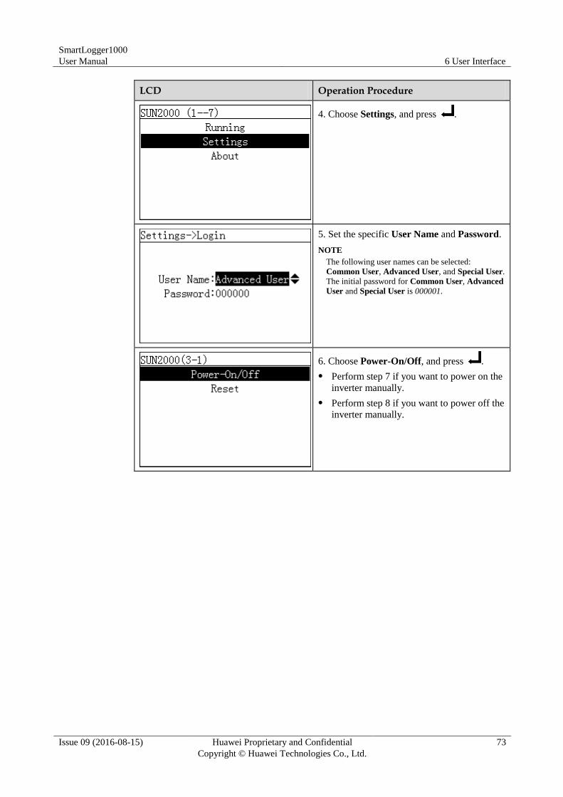
SmartLogger1000
User Manual 6 User Interface
Issue 09 (2016-08-15) Huawei Proprietary and Confidential
Copyright © Huawei Technologies Co., Ltd.
73
LCD Operation Procedure
4. Choose Settings, and press .
5. Set the specific User Name and Password.
NOTE
The following user names can be selected:
Common User, Advanced User, and Special User.
The initial password for Common User, Advanced
User and Special User is 000001.
6. Choose Power-On/Off, and press .
Perform step 7 if you want to power on the
inverter manually.
Perform step 8 if you want to power off the
inverter manually.
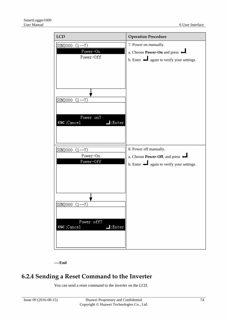
SmartLogger1000
User Manual 6 User Interface
Issue 09 (2016-08-15) Huawei Proprietary and Confidential
Copyright © Huawei Technologies Co., Ltd.
74
LCD Operation Procedure
7. Power on manually.
a. Choose Power-On and press .
b. Enter again to verify your settings.
8. Power off manually.
a. Choose Power-Off, and press .
b. Enter again to verify your settings.
----End
6.2.4 Sending a Reset Command to the Inverter
You can send a reset command to the inverter on the LCD.
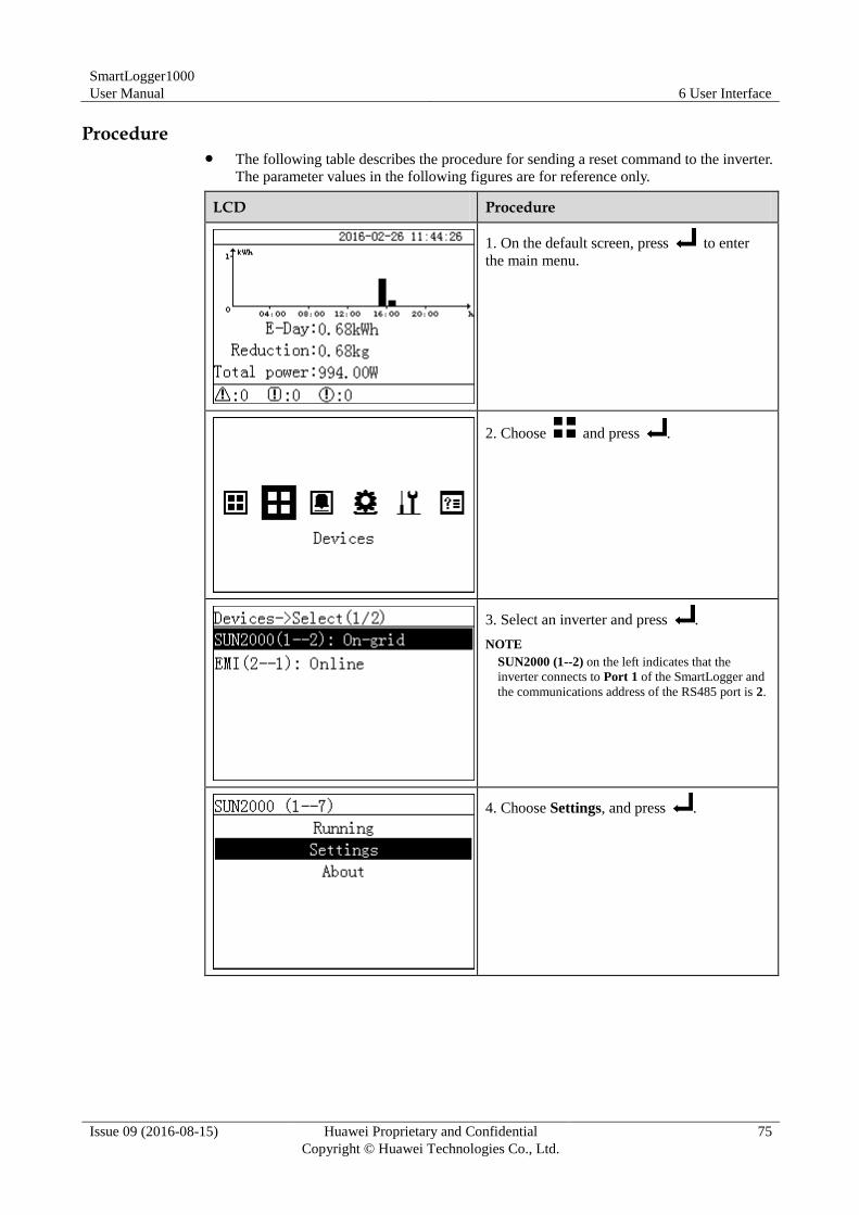
SmartLogger1000
User Manual 6 User Interface
Issue 09 (2016-08-15) Huawei Proprietary and Confidential
Copyright © Huawei Technologies Co., Ltd.
75
Procedure The following table describes the procedure for sending a reset command to the inverter.
The parameter values in the following figures are for reference only.
LCD Procedure
1. On the default screen, press to enter
the main menu.
2. Choose and press .
3. Select an inverter and press .
NOTE
SUN2000 (1--2) on the left indicates that the
inverter connects to Port 1 of the SmartLogger and
the communications address of the RS485 port is 2.
4. Choose Settings, and press .
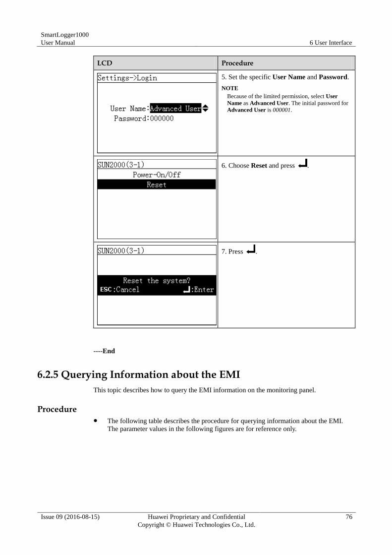
SmartLogger1000
User Manual 6 User Interface
Issue 09 (2016-08-15) Huawei Proprietary and Confidential
Copyright © Huawei Technologies Co., Ltd.
76
LCD Procedure
5. Set the specific User Name and Password.
NOTE
Because of the limited permission, select User
Name as Advanced User. The initial password for
Advanced User is 000001.
6. Choose Reset and press .
7. Press .
----End
6.2.5 Querying Information about the EMI
This topic describes how to query the EMI information on the monitoring panel.
Procedure The following table describes the procedure for querying information about the EMI.
The parameter values in the following figures are for reference only.
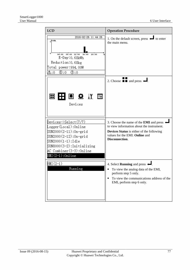
SmartLogger1000
User Manual 6 User Interface
Issue 09 (2016-08-15) Huawei Proprietary and Confidential
Copyright © Huawei Technologies Co., Ltd.
77
LCD Operation Procedure
1. On the default screen, press to enter
the main menu.
2. Choose and press .
3. Choose the name of the EMI and press
to view information about the instrument.
Devices Status is either of the following
values for the EMI: Online and
Disconnection.
4. Select Running and press .
To view the analog data of the EMI,
perform step 5 only.
To view the communications address of the
EMI, perform step 6 only.
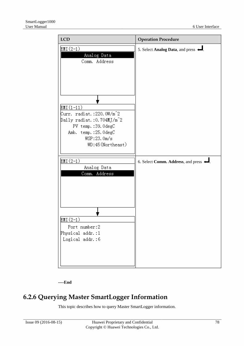
SmartLogger1000
User Manual 6 User Interface
Issue 09 (2016-08-15) Huawei Proprietary and Confidential
Copyright © Huawei Technologies Co., Ltd.
78
LCD Operation Procedure
5. Select Analog Data, and press .
6. Select Comm. Address, and press .
----End
6.2.6 Querying Master SmartLogger Information
This topic describes how to query Master SmartLogger information.
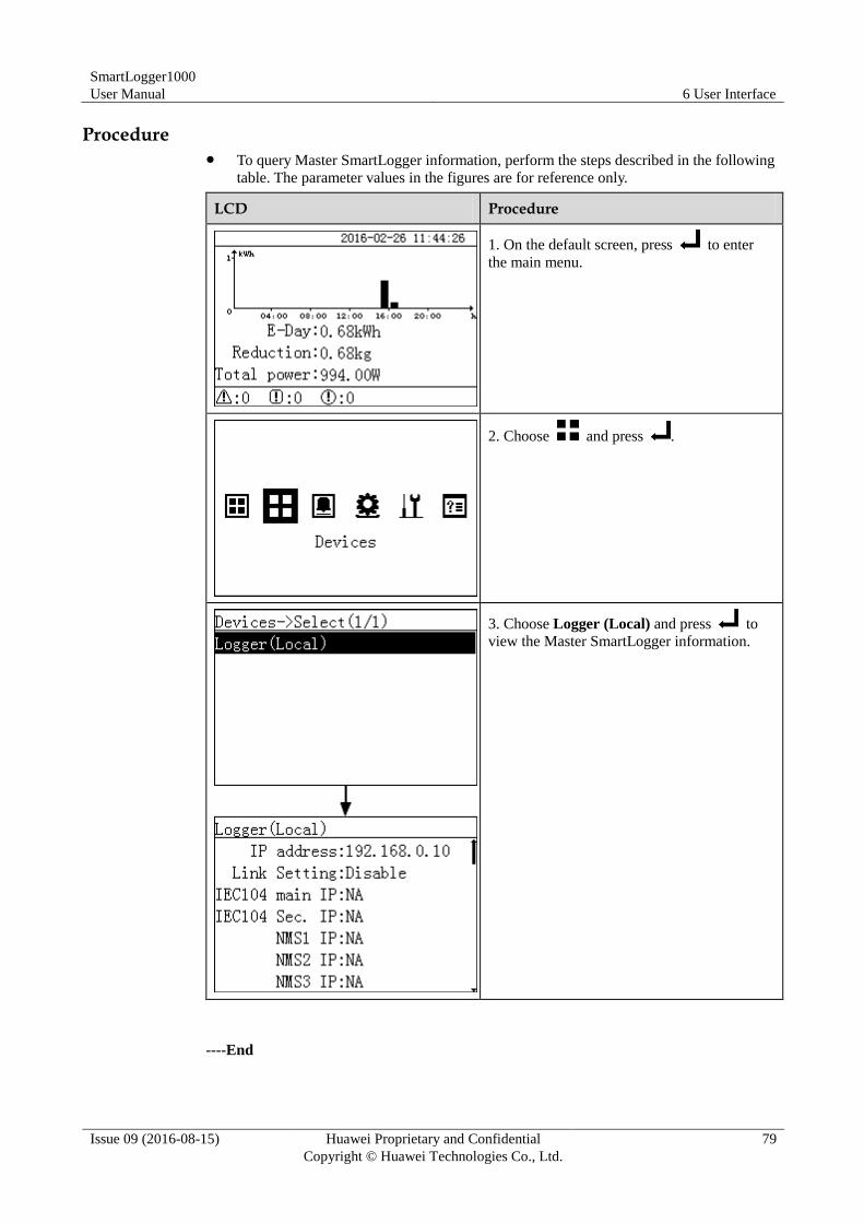
SmartLogger1000
User Manual 6 User Interface
Issue 09 (2016-08-15) Huawei Proprietary and Confidential
Copyright © Huawei Technologies Co., Ltd.
79
Procedure To query Master SmartLogger information, perform the steps described in the following
table. The parameter values in the figures are for reference only.
LCD Procedure
1. On the default screen, press to enter
the main menu.
2. Choose and press .
3. Choose Logger (Local) and press to
view the Master SmartLogger information.
----End
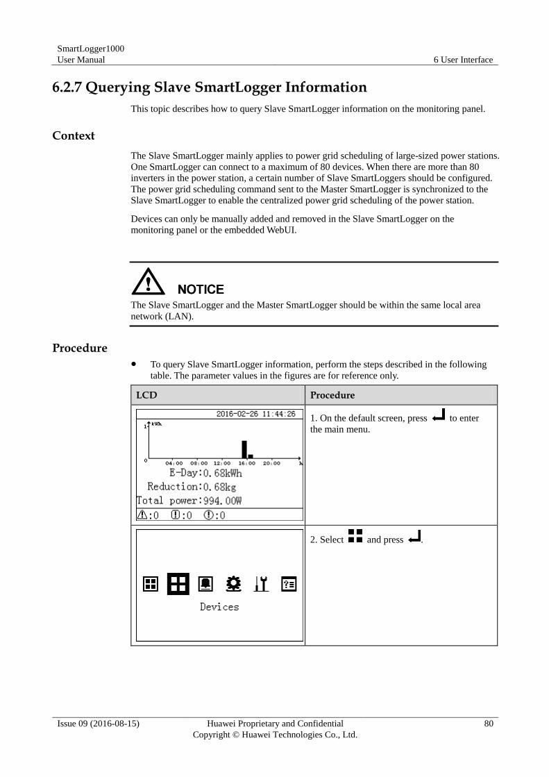
SmartLogger1000
User Manual 6 User Interface
Issue 09 (2016-08-15) Huawei Proprietary and Confidential
Copyright © Huawei Technologies Co., Ltd.
80
6.2.7 Querying Slave SmartLogger Information
This topic describes how to query Slave SmartLogger information on the monitoring panel.
Context
The Slave SmartLogger mainly applies to power grid scheduling of large-sized power stations.
One SmartLogger can connect to a maximum of 80 devices. When there are more than 80
inverters in the power station, a certain number of Slave SmartLoggers should be configured.
The power grid scheduling command sent to the Master SmartLogger is synchronized to the
Slave SmartLogger to enable the centralized power grid scheduling of the power station.
Devices can only be manually added and removed in the Slave SmartLogger on the
monitoring panel or the embedded WebUI.
The Slave SmartLogger and the Master SmartLogger should be within the same local area
network (LAN).
Procedure To query Slave SmartLogger information, perform the steps described in the following
table. The parameter values in the figures are for reference only.
LCD Procedure
1. On the default screen, press to enter
the main menu.
2. Select and press .
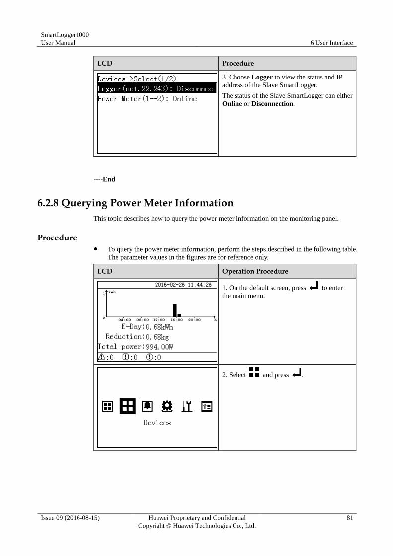
SmartLogger1000
User Manual 6 User Interface
Issue 09 (2016-08-15) Huawei Proprietary and Confidential
Copyright © Huawei Technologies Co., Ltd.
81
LCD Procedure
3. Choose Logger to view the status and IP
address of the Slave SmartLogger.
The status of the Slave SmartLogger can either
Online or Disconnection.
----End
6.2.8 Querying Power Meter Information
This topic describes how to query the power meter information on the monitoring panel.
Procedure To query the power meter information, perform the steps described in the following table.
The parameter values in the figures are for reference only.
LCD Operation Procedure
1. On the default screen, press to enter
the main menu.
2. Select and press .
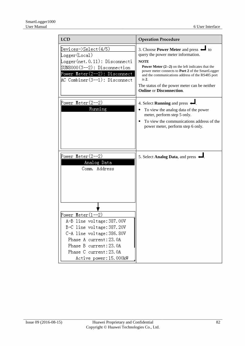
SmartLogger1000
User Manual 6 User Interface
Issue 09 (2016-08-15) Huawei Proprietary and Confidential
Copyright © Huawei Technologies Co., Ltd.
82
LCD Operation Procedure
3. Choose Power Meter and press to
query the power meter information.
NOTE
Power Meter (2--2) on the left indicates that the
power meter connects to Port 2 of the SmartLogger
and the communications address of the RS485 port
is 2.
The status of the power meter can be neither
Online or Disconnection.
4. Select Running and press .
To view the analog data of the power
meter, perform step 5 only.
To view the communications address of the
power meter, perform step 6 only.
5. Select Analog Data, and press .
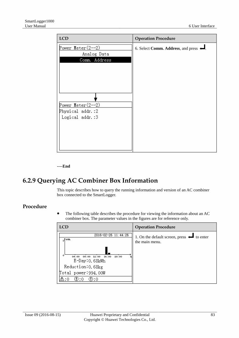
SmartLogger1000
User Manual 6 User Interface
Issue 09 (2016-08-15) Huawei Proprietary and Confidential
Copyright © Huawei Technologies Co., Ltd.
83
LCD Operation Procedure
6. Select Comm. Address, and press .
----End
6.2.9 Querying AC Combiner Box Information
This topic describes how to query the running information and version of an AC combiner
box connected to the SmartLogger.
Procedure The following table describes the procedure for viewing the information about an AC
combiner box. The parameter values in the figures are for reference only.
LCD Operation Procedure
1. On the default screen, press to enter
the main menu.
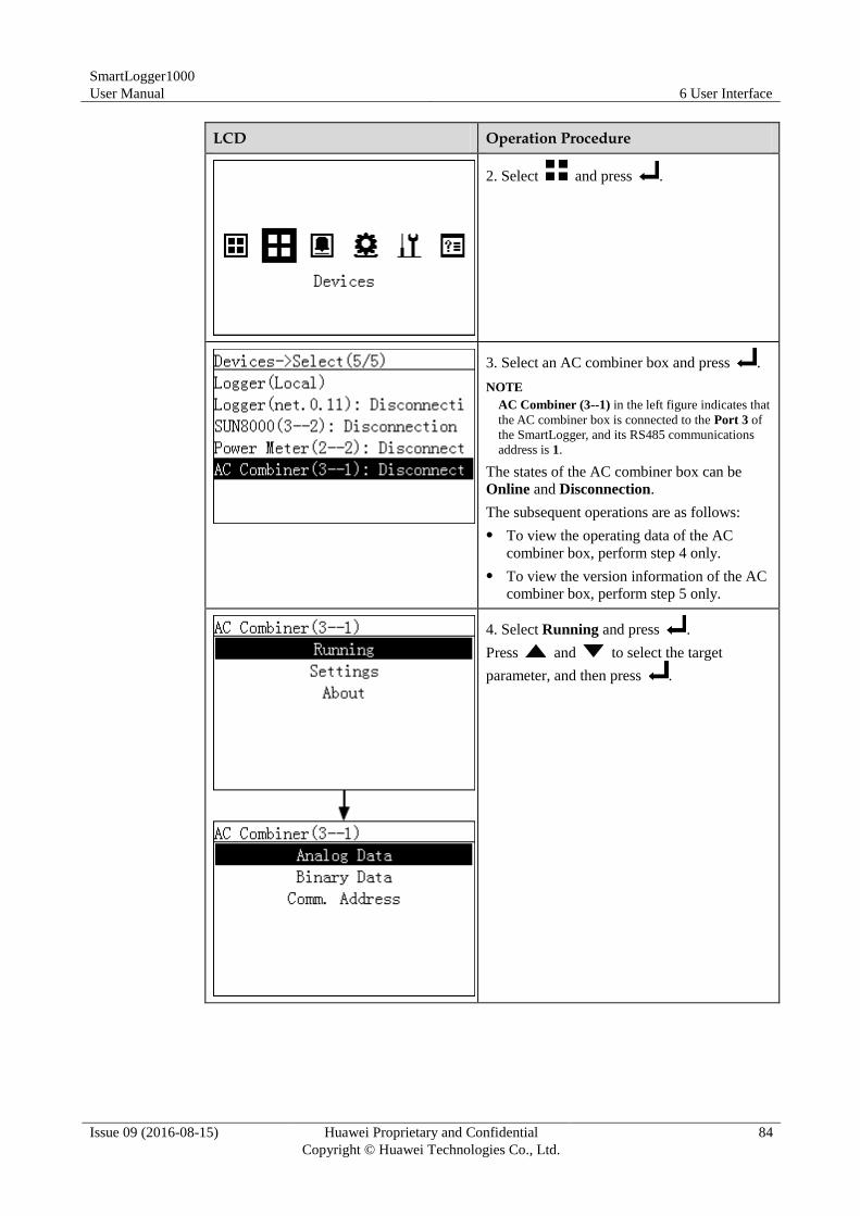
SmartLogger1000
User Manual 6 User Interface
Issue 09 (2016-08-15) Huawei Proprietary and Confidential
Copyright © Huawei Technologies Co., Ltd.
84
LCD Operation Procedure
2. Select and press .
3. Select an AC combiner box and press .
NOTE
AC Combiner (3--1) in the left figure indicates that
the AC combiner box is connected to the Port 3 of
the SmartLogger, and its RS485 communications
address is 1.
The states of the AC combiner box can be
Online and Disconnection.
The subsequent operations are as follows:
To view the operating data of the AC
combiner box, perform step 4 only.
To view the version information of the AC
combiner box, perform step 5 only.
4. Select Running and press .
Press and to select the target
parameter, and then press .
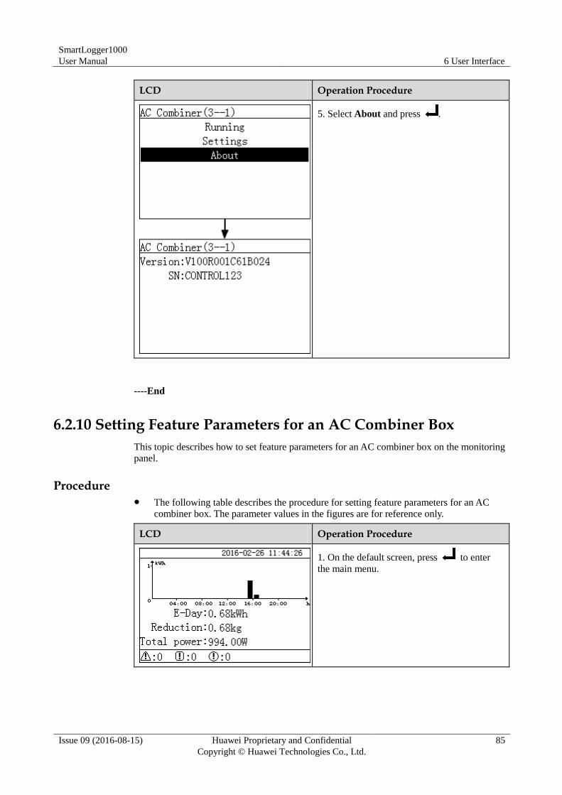
SmartLogger1000
User Manual 6 User Interface
Issue 09 (2016-08-15) Huawei Proprietary and Confidential
Copyright © Huawei Technologies Co., Ltd.
85
LCD Operation Procedure
5. Select About and press .
----End
6.2.10 Setting Feature Parameters for an AC Combiner Box
This topic describes how to set feature parameters for an AC combiner box on the monitoring
panel.
Procedure The following table describes the procedure for setting feature parameters for an AC
combiner box. The parameter values in the figures are for reference only.
LCD Operation Procedure
1. On the default screen, press to enter
the main menu.
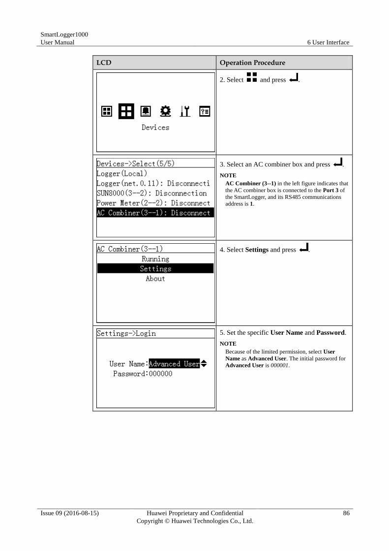
SmartLogger1000
User Manual 6 User Interface
Issue 09 (2016-08-15) Huawei Proprietary and Confidential
Copyright © Huawei Technologies Co., Ltd.
86
LCD Operation Procedure
2. Select and press .
3. Select an AC combiner box and press .
NOTE
AC Combiner (3--1) in the left figure indicates that
the AC combiner box is connected to the Port 3 of
the SmartLogger, and its RS485 communications
address is 1.
4. Select Settings and press .
5. Set the specific User Name and Password.
NOTE
Because of the limited permission, select User
Name as Advanced User. The initial password for
Advanced User is 000001.
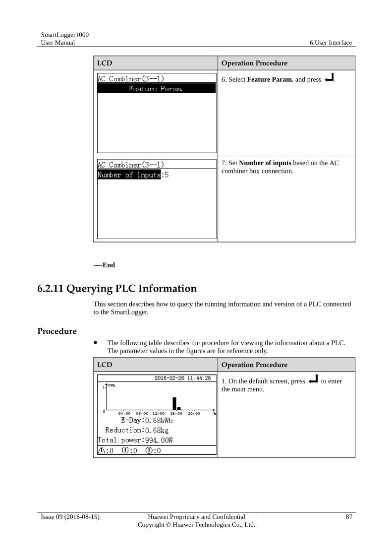
SmartLogger1000
User Manual 6 User Interface
Issue 09 (2016-08-15) Huawei Proprietary and Confidential
Copyright © Huawei Technologies Co., Ltd.
87
LCD Operation Procedure
6. Select Feature Param. and press .
7. Set Number of inputs based on the AC
combiner box connection.
----End
6.2.11 Querying PLC Information
This section describes how to query the running information and version of a PLC connected
to the SmartLogger.
Procedure The following table describes the procedure for viewing the information about a PLC.
The parameter values in the figures are for reference only.
LCD Operation Procedure
1. On the default screen, press to enter
the main menu.
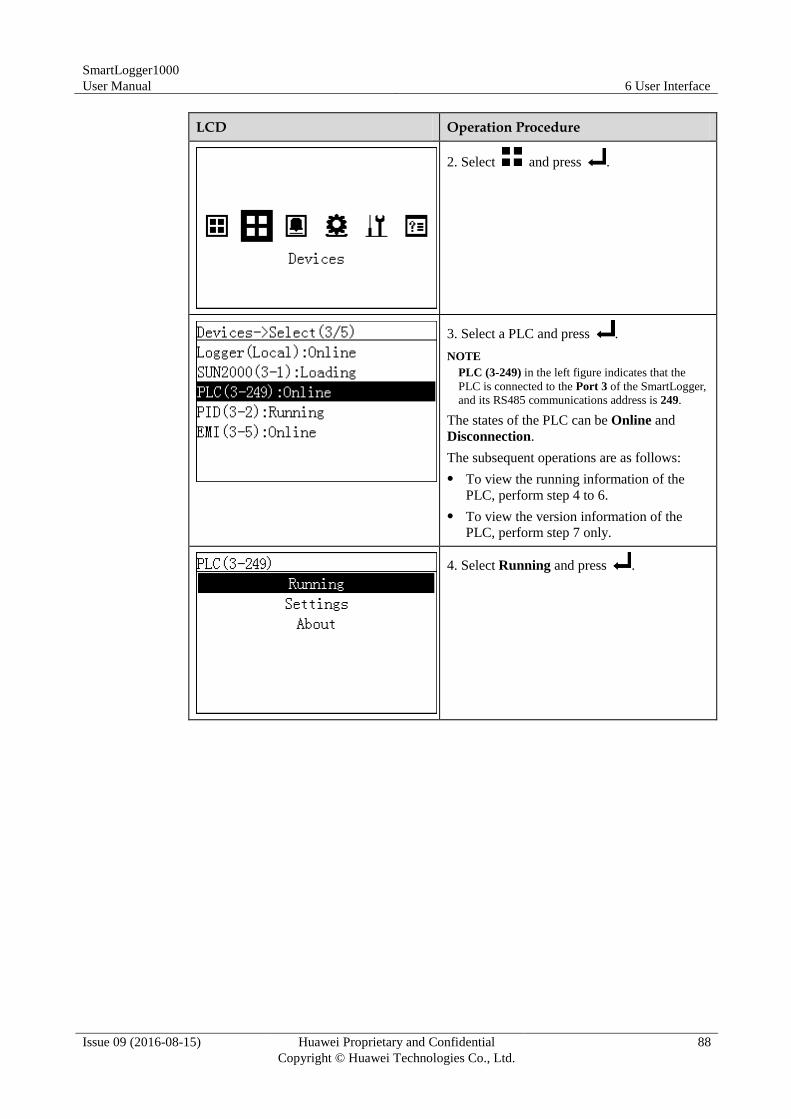
SmartLogger1000
User Manual 6 User Interface
Issue 09 (2016-08-15) Huawei Proprietary and Confidential
Copyright © Huawei Technologies Co., Ltd.
88
LCD Operation Procedure
2. Select and press .
3. Select a PLC and press .
NOTE
PLC (3-249) in the left figure indicates that the
PLC is connected to the Port 3 of the SmartLogger,
and its RS485 communications address is 249.
The states of the PLC can be Online and
Disconnection.
The subsequent operations are as follows:
To view the running information of the
PLC, perform step 4 to 6.
To view the version information of the
PLC, perform step 7 only.
4. Select Running and press .
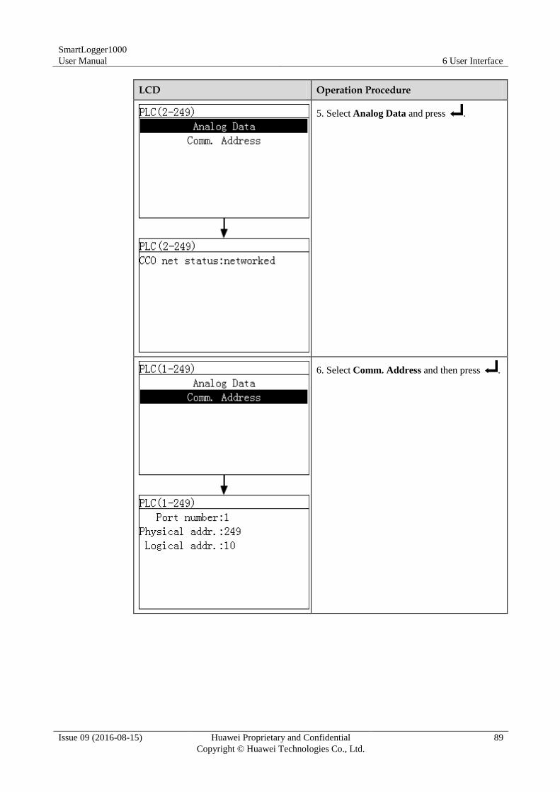
SmartLogger1000
User Manual 6 User Interface
Issue 09 (2016-08-15) Huawei Proprietary and Confidential
Copyright © Huawei Technologies Co., Ltd.
89
LCD Operation Procedure
5. Select Analog Data and press .
6. Select Comm. Address and then press .
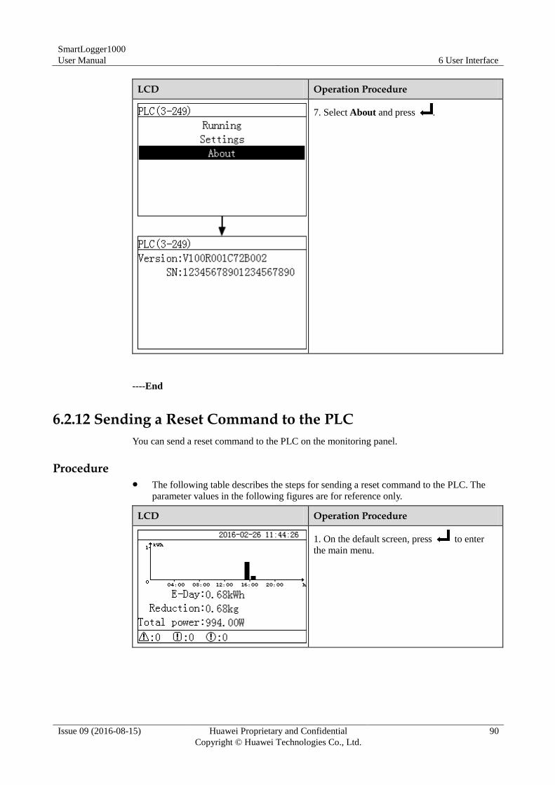
SmartLogger1000
User Manual 6 User Interface
Issue 09 (2016-08-15) Huawei Proprietary and Confidential
Copyright © Huawei Technologies Co., Ltd.
90
LCD Operation Procedure
7. Select About and press .
----End
6.2.12 Sending a Reset Command to the PLC
You can send a reset command to the PLC on the monitoring panel.
Procedure The following table describes the steps for sending a reset command to the PLC. The
parameter values in the following figures are for reference only.
LCD Operation Procedure
1. On the default screen, press to enter
the main menu.

SmartLogger1000
User Manual 6 User Interface
Issue 09 (2016-08-15) Huawei Proprietary and Confidential
Copyright © Huawei Technologies Co., Ltd.
91
LCD Operation Procedure
2. Choose and press .
3. Select a PLC and press .
NOTE
PLC (3-249) in the left figure indicates that the
PLC is connected to the Port 3 of the SmartLogger,
and its RS485 communications address is 249.
4. Select Settings and press .
5. Set the specific User Name and Password.
NOTE
Because of the limited permission, select User
Name as Advanced User. The initial password for
Advanced User is 000001.
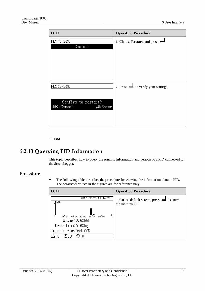
SmartLogger1000
User Manual 6 User Interface
Issue 09 (2016-08-15) Huawei Proprietary and Confidential
Copyright © Huawei Technologies Co., Ltd.
92
LCD Operation Procedure
6. Choose Restart, and press .
7. Press to verify your settings.
----End
6.2.13 Querying PID Information
This topic describes how to query the running information and version of a PID connected to
the SmartLogger.
Procedure The following table describes the procedure for viewing the information about a PID.
The parameter values in the figures are for reference only.
LCD Operation Procedure
1. On the default screen, press to enter
the main menu.
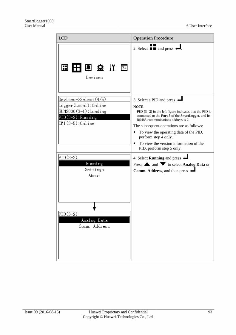
SmartLogger1000
User Manual 6 User Interface
Issue 09 (2016-08-15) Huawei Proprietary and Confidential
Copyright © Huawei Technologies Co., Ltd.
93
LCD Operation Procedure
2. Select and press .
3. Select a PID and press .
NOTE
PID (3--2) in the left figure indicates that the PID is
connected to the Port 3 of the SmartLogger, and its
RS485 communications address is 2.
The subsequent operations are as follows:
To view the operating data of the PID,
perform step 4 only.
To view the version information of the
PID, perform step 5 only.
4. Select Running and press .
Press and to select Analog Data or
Comm. Address, and then press .
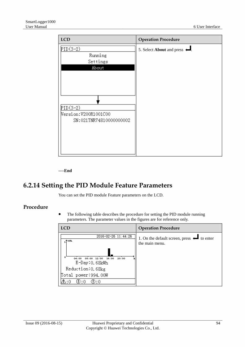
SmartLogger1000
User Manual 6 User Interface
Issue 09 (2016-08-15) Huawei Proprietary and Confidential
Copyright © Huawei Technologies Co., Ltd.
94
LCD Operation Procedure
5. Select About and press .
----End
6.2.14 Setting the PID Module Feature Parameters
You can set the PID module Feature parameters on the LCD.
Procedure The following table describes the procedure for setting the PID module running
parameters. The parameter values in the figures are for reference only.
LCD Operation Procedure
1. On the default screen, press to enter
the main menu.
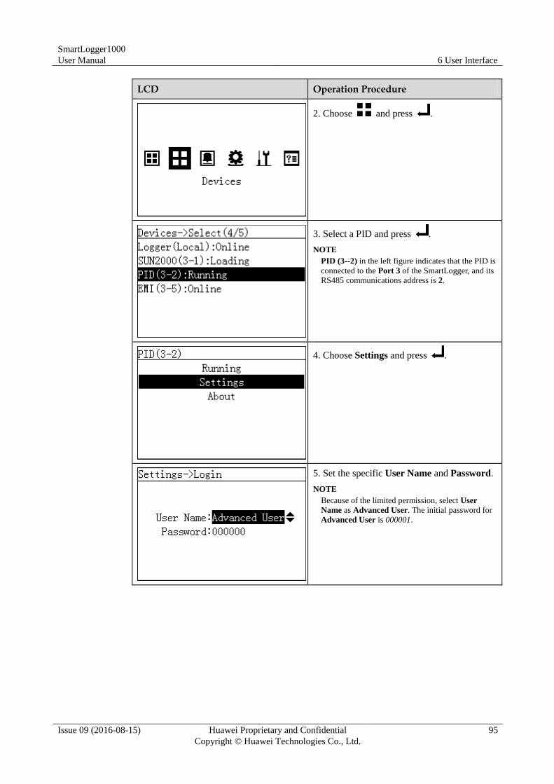
SmartLogger1000
User Manual 6 User Interface
Issue 09 (2016-08-15) Huawei Proprietary and Confidential
Copyright © Huawei Technologies Co., Ltd.
95
LCD Operation Procedure
2. Choose and press .
3. Select a PID and press .
NOTE
PID (3--2) in the left figure indicates that the PID is
connected to the Port 3 of the SmartLogger, and its
RS485 communications address is 2.
4. Choose Settings and press .
5. Set the specific User Name and Password.
NOTE
Because of the limited permission, select User
Name as Advanced User. The initial password for
Advanced User is 000001.
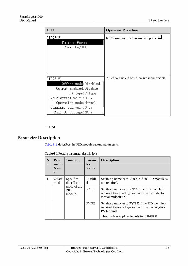
SmartLogger1000
User Manual 6 User Interface
Issue 09 (2016-08-15) Huawei Proprietary and Confidential
Copyright © Huawei Technologies Co., Ltd.
96
LCD Operation Procedure
6. Choose Feature Param. and press .
7. Set parameters based on site requirements.
----End
Parameter Description
Table 6-1 describes the PID module feature parameters.
Table 6-1 Feature parameter descriptions
No.
Parameter Name
Function Parameter Value
Description
1 Offset
mode
Specifies
the offset
mode of the
PID
module.
Disable
d
Set this parameter to Disable if the PID module is
not required.
N/PE Set this parameter to N/PE if the PID module is
required to use voltage output from the inductor
virtual midpoint N.
PV/PE Set this parameter to PV/PE if the PID module is
required to use voltage output from the negative
PV terminal.
This mode is applicable only to SUN8000.
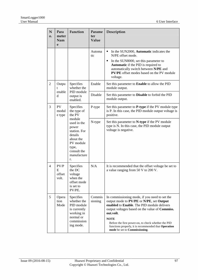
SmartLogger1000
User Manual 6 User Interface
Issue 09 (2016-08-15) Huawei Proprietary and Confidential
Copyright © Huawei Technologies Co., Ltd.
97
No.
Parameter Name
Function Parameter Value
Description
Automa
tic
In the SUN2000, Automatic indicates the
N/PE offset mode.
In the SUN8000, set this parameter to
Automatic if the PID is required to
automatically switch between N/PE and
PV/PE offset modes based on the PV module
voltage.
2 Outpu
t
enable
d
Specifies
whether the
PID module
output is
enabled.
Enable Set this parameter to Enable to allow the PID
module output.
Disable Set this parameter to Disable to forbid the PID
module output.
3 PV
modul
e type
Specifies
the type of
the PV
module
used in the
power
station. For
details
about the
PV module
type,
consult the
manufacture
r.
P-type Set this parameter to P-type if the PV module type
is P. In this case, the PID module output voltage is
positive.
N-type Set this parameter to N-type if the PV module
type is N. In this case, the PID module output
voltage is negative.
4 PV/P
E
offset
volt.
Specifies
the DC
voltage
when the
offset mode
is set to
PV/PE.
N/A It is recommended that the offset voltage be set to
a value ranging from 50 V to 200 V.
5 Opera
tion
Mode
Specifies
whether the
PID module
is currently
working in
normal or
commission
ing mode.
Commis
sioning
In commissioning mode, if you need to set the
output mode to PV/PE or N/PE, set Output
enabled to Enable. The PID module delivers
output voltages based on the value of Commiss.
out.volt.
NOTE
Before the first power-on, to check whether the PID
functions properly, it is recommended that Operation
mode be set to Commissioning.
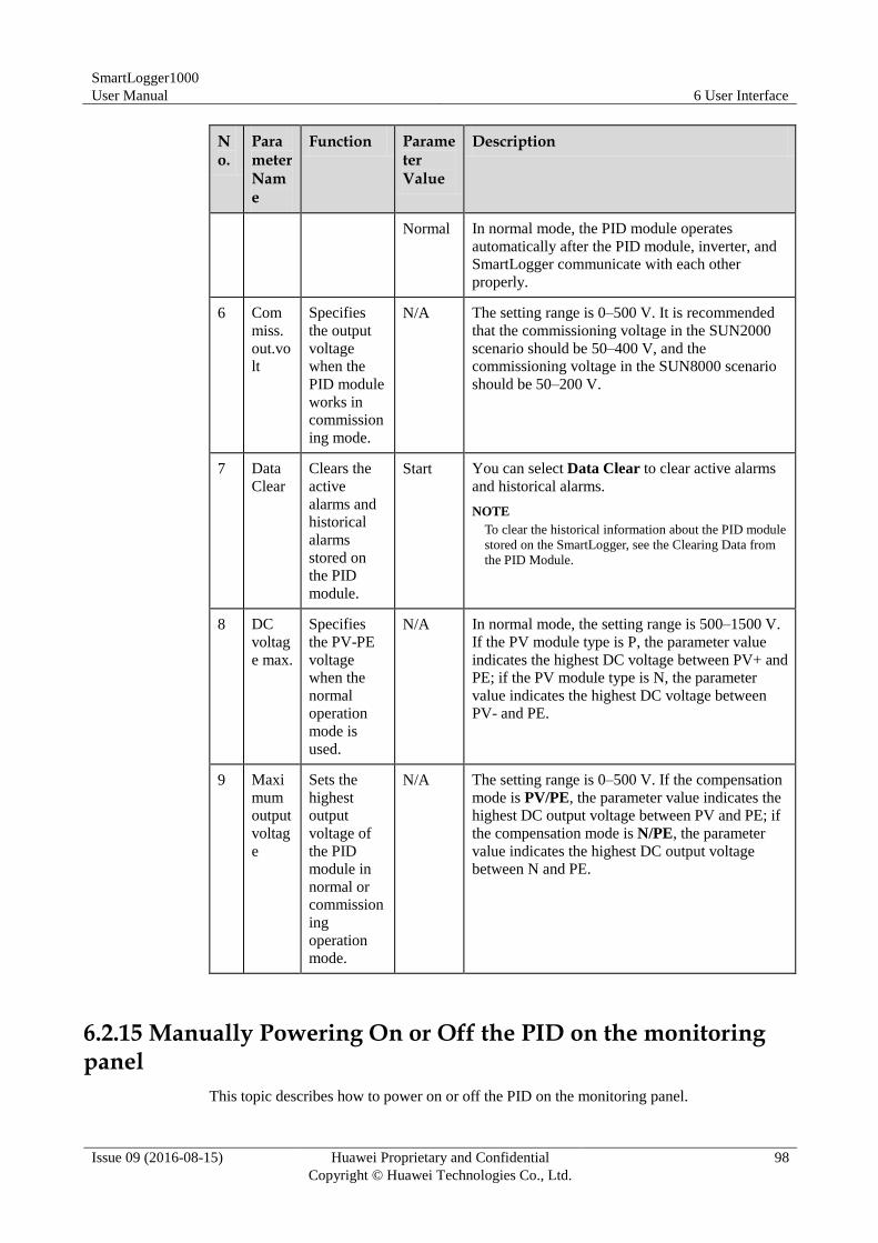
SmartLogger1000
User Manual 6 User Interface
Issue 09 (2016-08-15) Huawei Proprietary and Confidential
Copyright © Huawei Technologies Co., Ltd.
98
No.
Parameter Name
Function Parameter Value
Description
Normal In normal mode, the PID module operates
automatically after the PID module, inverter, and
SmartLogger communicate with each other
properly.
6 Com
miss.
out.vo
lt
Specifies
the output
voltage
when the
PID module
works in
commission
ing mode.
N/A The setting range is 0–500 V. It is recommended
that the commissioning voltage in the SUN2000
scenario should be 50–400 V, and the
commissioning voltage in the SUN8000 scenario
should be 50–200 V.
7 Data
Clear
Clears the
active
alarms and
historical
alarms
stored on
the PID
module.
Start You can select Data Clear to clear active alarms
and historical alarms.
NOTE
To clear the historical information about the PID module
stored on the SmartLogger, see the Clearing Data from
the PID Module.
8 DC
voltag
e max.
Specifies
the PV-PE
voltage
when the
normal
operation
mode is
used.
N/A In normal mode, the setting range is 500–1500 V.
If the PV module type is P, the parameter value
indicates the highest DC voltage between PV+ and
PE; if the PV module type is N, the parameter
value indicates the highest DC voltage between
PV- and PE.
9 Maxi
mum
output
voltag
e
Sets the
highest
output
voltage of
the PID
module in
normal or
commission
ing
operation
mode.
N/A The setting range is 0–500 V. If the compensation
mode is PV/PE, the parameter value indicates the
highest DC output voltage between PV and PE; if
the compensation mode is N/PE, the parameter
value indicates the highest DC output voltage
between N and PE.
6.2.15 Manually Powering On or Off the PID on the monitoring panel
This topic describes how to power on or off the PID on the monitoring panel.
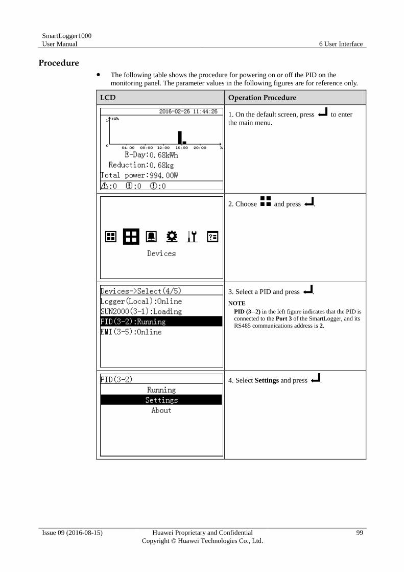
SmartLogger1000
User Manual 6 User Interface
Issue 09 (2016-08-15) Huawei Proprietary and Confidential
Copyright © Huawei Technologies Co., Ltd.
99
Procedure The following table shows the procedure for powering on or off the PID on the
monitoring panel. The parameter values in the following figures are for reference only.
LCD Operation Procedure
1. On the default screen, press to enter
the main menu.
2. Choose and press .
3. Select a PID and press .
NOTE
PID (3--2) in the left figure indicates that the PID is
connected to the Port 3 of the SmartLogger, and its
RS485 communications address is 2.
4. Select Settings and press .
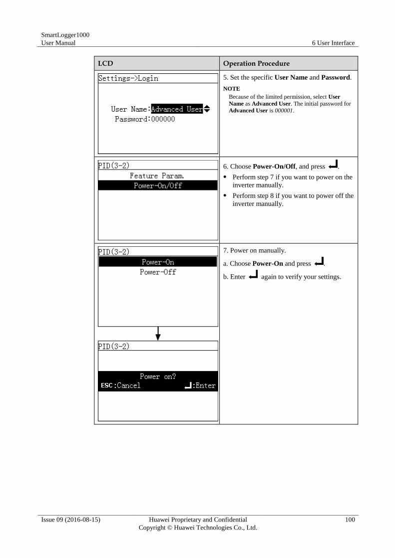
SmartLogger1000
User Manual 6 User Interface
Issue 09 (2016-08-15) Huawei Proprietary and Confidential
Copyright © Huawei Technologies Co., Ltd.
100
LCD Operation Procedure
5. Set the specific User Name and Password.
NOTE
Because of the limited permission, select User
Name as Advanced User. The initial password for
Advanced User is 000001.
6. Choose Power-On/Off, and press .
Perform step 7 if you want to power on the
inverter manually.
Perform step 8 if you want to power off the
inverter manually.
7. Power on manually.
a. Choose Power-On and press .
b. Enter again to verify your settings.
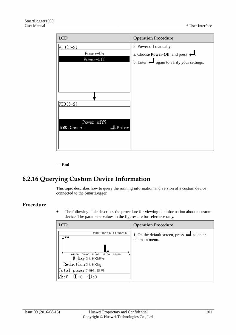
SmartLogger1000
User Manual 6 User Interface
Issue 09 (2016-08-15) Huawei Proprietary and Confidential
Copyright © Huawei Technologies Co., Ltd.
101
LCD Operation Procedure
8. Power off manually.
a. Choose Power-Off, and press .
b. Enter again to verify your settings.
----End
6.2.16 Querying Custom Device Information
This topic describes how to query the running information and version of a custom device
connected to the SmartLogger.
Procedure The following table describes the procedure for viewing the information about a custom
device. The parameter values in the figures are for reference only.
LCD Operation Procedure
1. On the default screen, press to enter
the main menu.
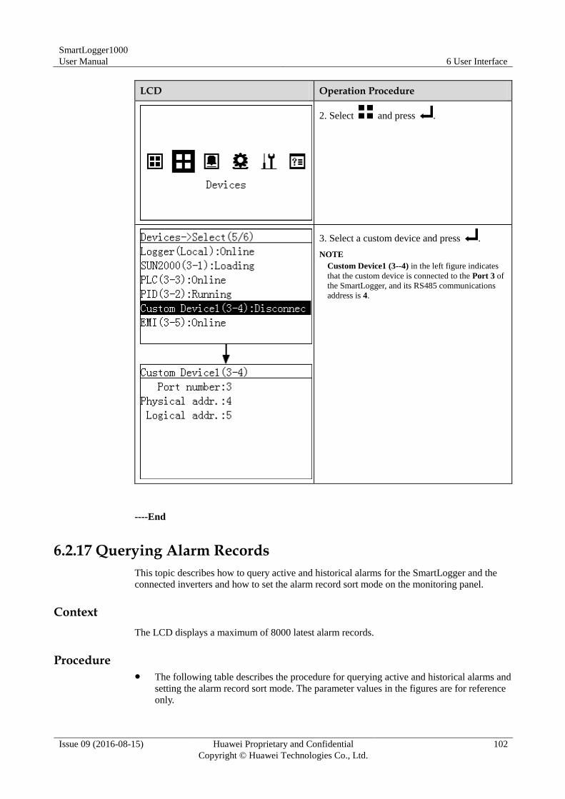
SmartLogger1000
User Manual 6 User Interface
Issue 09 (2016-08-15) Huawei Proprietary and Confidential
Copyright © Huawei Technologies Co., Ltd.
102
LCD Operation Procedure
2. Select and press .
3. Select a custom device and press .
NOTE
Custom Device1 (3--4) in the left figure indicates
that the custom device is connected to the Port 3 of
the SmartLogger, and its RS485 communications
address is 4.
----End
6.2.17 Querying Alarm Records
This topic describes how to query active and historical alarms for the SmartLogger and the
connected inverters and how to set the alarm record sort mode on the monitoring panel.
Context
The LCD displays a maximum of 8000 latest alarm records.
Procedure The following table describes the procedure for querying active and historical alarms and
setting the alarm record sort mode. The parameter values in the figures are for reference
only.
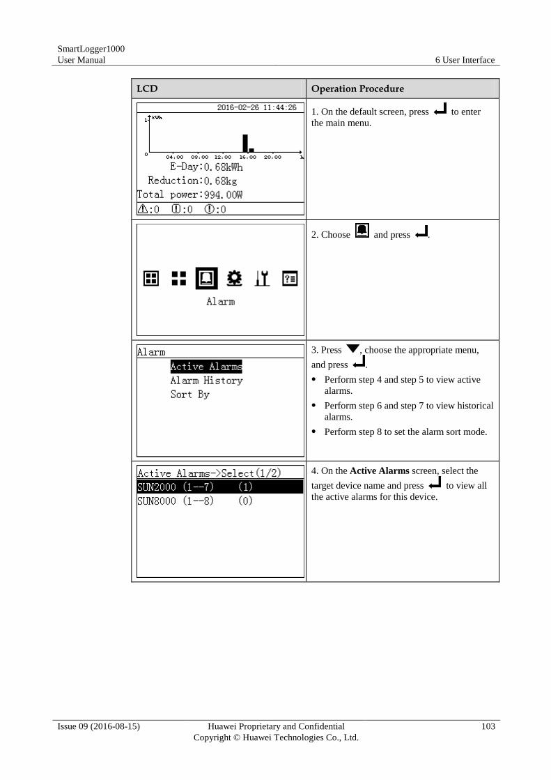
SmartLogger1000
User Manual 6 User Interface
Issue 09 (2016-08-15) Huawei Proprietary and Confidential
Copyright © Huawei Technologies Co., Ltd.
103
LCD Operation Procedure
1. On the default screen, press to enter
the main menu.
2. Choose and press .
3. Press , choose the appropriate menu,
and press .
Perform step 4 and step 5 to view active
alarms.
Perform step 6 and step 7 to view historical
alarms.
Perform step 8 to set the alarm sort mode.
4. On the Active Alarms screen, select the
target device name and press to view all
the active alarms for this device.
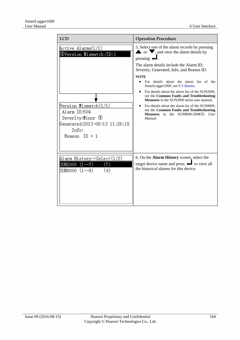
SmartLogger1000
User Manual 6 User Interface
Issue 09 (2016-08-15) Huawei Proprietary and Confidential
Copyright © Huawei Technologies Co., Ltd.
104
LCD Operation Procedure
5. Select one of the alarm records by pressing
or , and view the alarm details by
pressing .
The alarm details include the Alarm ID,
Severity, Generated, Info, and Reason ID.
NOTE
For details about the alarm list of the
SmartLogger1000, see 9.3 Alarms.
For details about the alarm list of the SUN2000,
see the Common Faults and Troubleshooting
Measures in the SUN2000 series user manual.
For details about the alarm list of the SUN8000,
see the Common Faults and Troubleshooting
Measures in the SUN8000-500KTL User
Manual.
6. On the Alarm History screen, select the
target device name and press to view all
the historical alarms for this device.
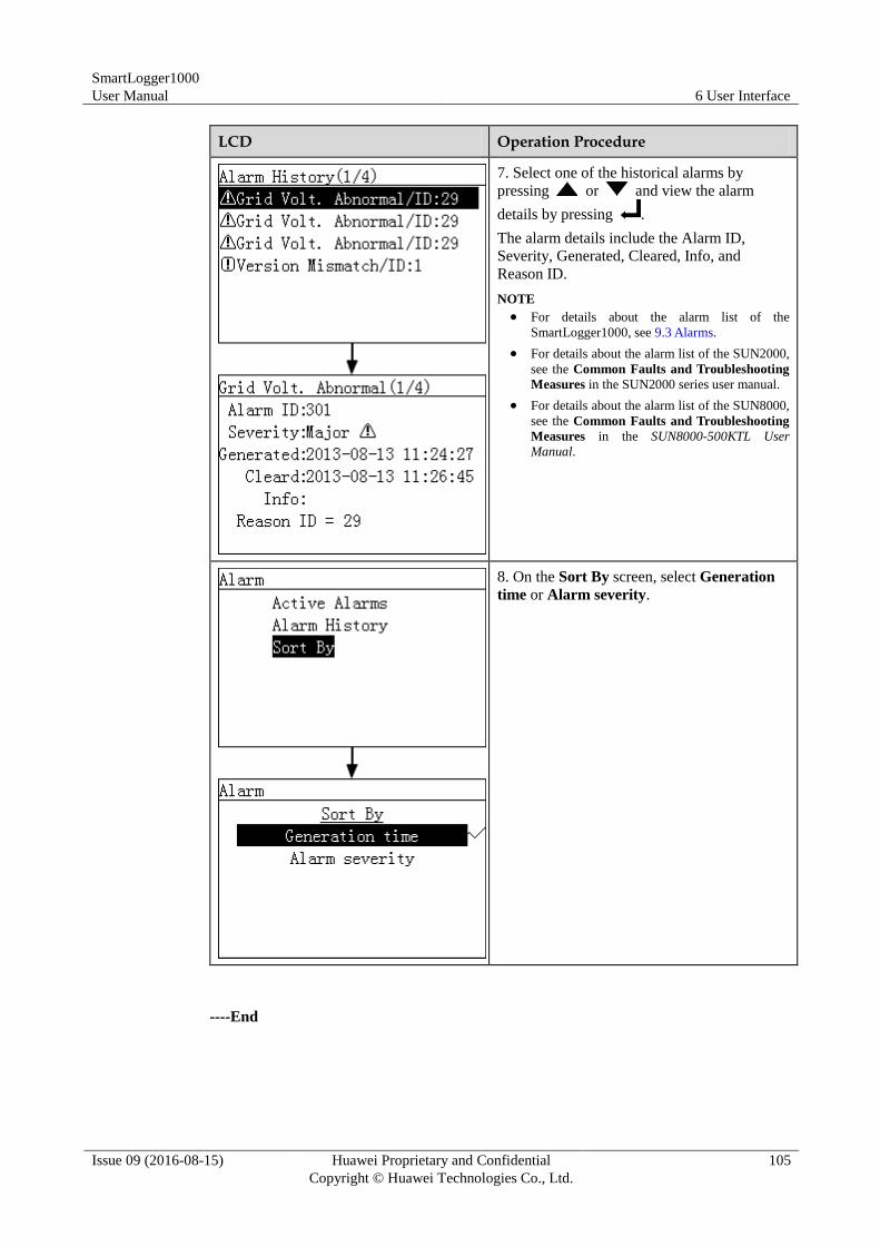
SmartLogger1000
User Manual 6 User Interface
Issue 09 (2016-08-15) Huawei Proprietary and Confidential
Copyright © Huawei Technologies Co., Ltd.
105
LCD Operation Procedure
7. Select one of the historical alarms by
pressing or and view the alarm
details by pressing .
The alarm details include the Alarm ID,
Severity, Generated, Cleared, Info, and
Reason ID.
NOTE
For details about the alarm list of the
SmartLogger1000, see 9.3 Alarms.
For details about the alarm list of the SUN2000,
see the Common Faults and Troubleshooting
Measures in the SUN2000 series user manual.
For details about the alarm list of the SUN8000,
see the Common Faults and Troubleshooting
Measures in the SUN8000-500KTL User
Manual.
8. On the Sort By screen, select Generation
time or Alarm severity.
----End
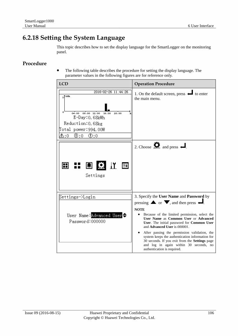
SmartLogger1000
User Manual 6 User Interface
Issue 09 (2016-08-15) Huawei Proprietary and Confidential
Copyright © Huawei Technologies Co., Ltd.
106
6.2.18 Setting the System Language
This topic describes how to set the display language for the SmartLogger on the monitoring
panel.
Procedure The following table describes the procedure for setting the display language. The
parameter values in the following figures are for reference only.
LCD Operation Procedure
1. On the default screen, press to enter
the main menu.
2. Choose and press .
3. Specify the User Name and Password by
pressing or , and then press .
NOTE
Because of the limited permission, select the
User Name as Common User or Advanced
User. The initial password for Common User
and Advanced User is 000001.
After passing the permission validation, the
system keeps the authentication information for
30 seconds. If you exit from the Settings page
and log in again within 30 seconds, no
authentication is required.
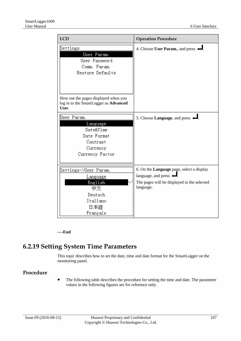
SmartLogger1000
User Manual 6 User Interface
Issue 09 (2016-08-15) Huawei Proprietary and Confidential
Copyright © Huawei Technologies Co., Ltd.
107
LCD Operation Procedure
Here use the pages displayed when you
log in to the SmartLogger as Advanced
User.
4. Choose User Param., and press .
5. Choose Language, and press .
6. On the Language page, select a display
language, and press .
The pages will be displayed in the selected
language.
----End
6.2.19 Setting System Time Parameters
This topic describes how to set the date, time and date format for the SmartLogger on the
monitoring panel.
Procedure The following table describes the procedure for setting the time and date. The parameter
values in the following figures are for reference only.
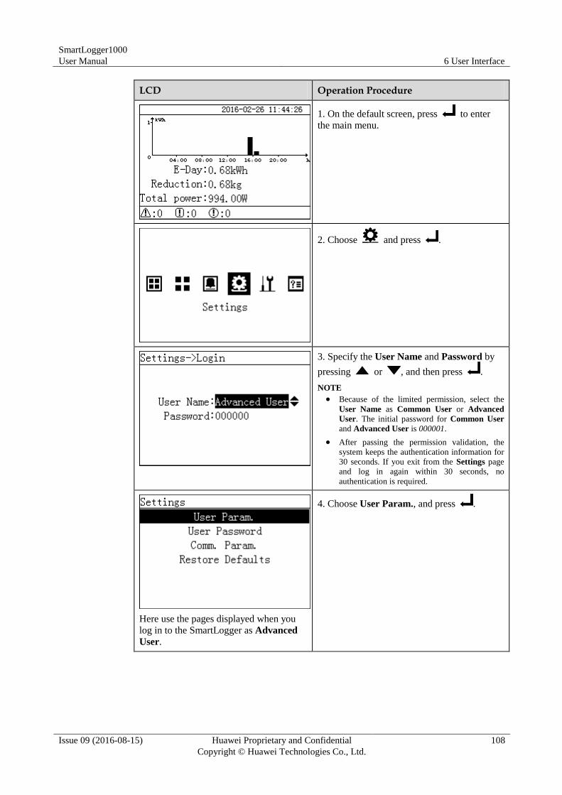
SmartLogger1000
User Manual 6 User Interface
Issue 09 (2016-08-15) Huawei Proprietary and Confidential
Copyright © Huawei Technologies Co., Ltd.
108
LCD Operation Procedure
1. On the default screen, press to enter
the main menu.
2. Choose and press .
3. Specify the User Name and Password by
pressing or , and then press .
NOTE
Because of the limited permission, select the
User Name as Common User or Advanced
User. The initial password for Common User
and Advanced User is 000001.
After passing the permission validation, the
system keeps the authentication information for
30 seconds. If you exit from the Settings page
and log in again within 30 seconds, no
authentication is required.
Here use the pages displayed when you
log in to the SmartLogger as Advanced
User.
4. Choose User Param., and press .
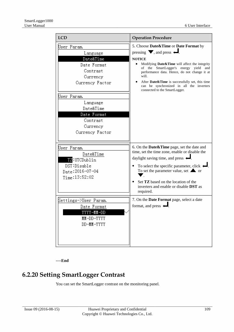
SmartLogger1000
User Manual 6 User Interface
Issue 09 (2016-08-15) Huawei Proprietary and Confidential
Copyright © Huawei Technologies Co., Ltd.
109
LCD Operation Procedure
5. Choose Date&Time or Date Format by
pressing , and press .
NOTICE
Modifying Date&Time will affect the integrity
of the SmartLogger's energy yield and
performance data. Hence, do not change it at
will.
After Date&Time is successfully set, this time
can be synchronized in all the inverters
connected to the SmartLogger.
6. On the Date&Time page, set the date and
time, set the time zone, enable or disable the
daylight saving time, and press .
To select the specific parameter, click .
To set the parameter value, set or
.
Set TZ based on the location of the
inverters and enable or disable DST as
required.
7. On the Date Format page, select a date
format, and press .
----End
6.2.20 Setting SmartLogger Contrast
You can set the SmartLogger contrast on the monitoring panel.
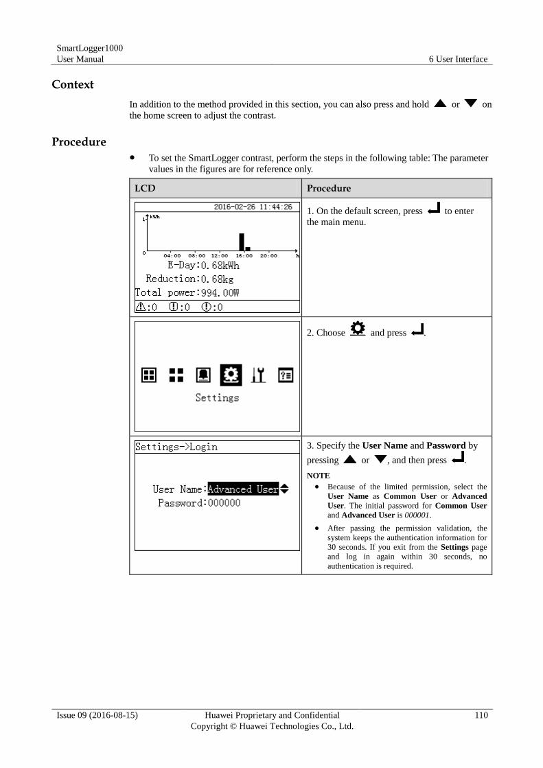
SmartLogger1000
User Manual 6 User Interface
Issue 09 (2016-08-15) Huawei Proprietary and Confidential
Copyright © Huawei Technologies Co., Ltd.
110
Context
In addition to the method provided in this section, you can also press and hold or on
the home screen to adjust the contrast.
Procedure To set the SmartLogger contrast, perform the steps in the following table: The parameter
values in the figures are for reference only.
LCD Procedure
1. On the default screen, press to enter
the main menu.
2. Choose and press .
3. Specify the User Name and Password by
pressing or , and then press .
NOTE
Because of the limited permission, select the
User Name as Common User or Advanced
User. The initial password for Common User
and Advanced User is 000001.
After passing the permission validation, the
system keeps the authentication information for
30 seconds. If you exit from the Settings page
and log in again within 30 seconds, no
authentication is required.
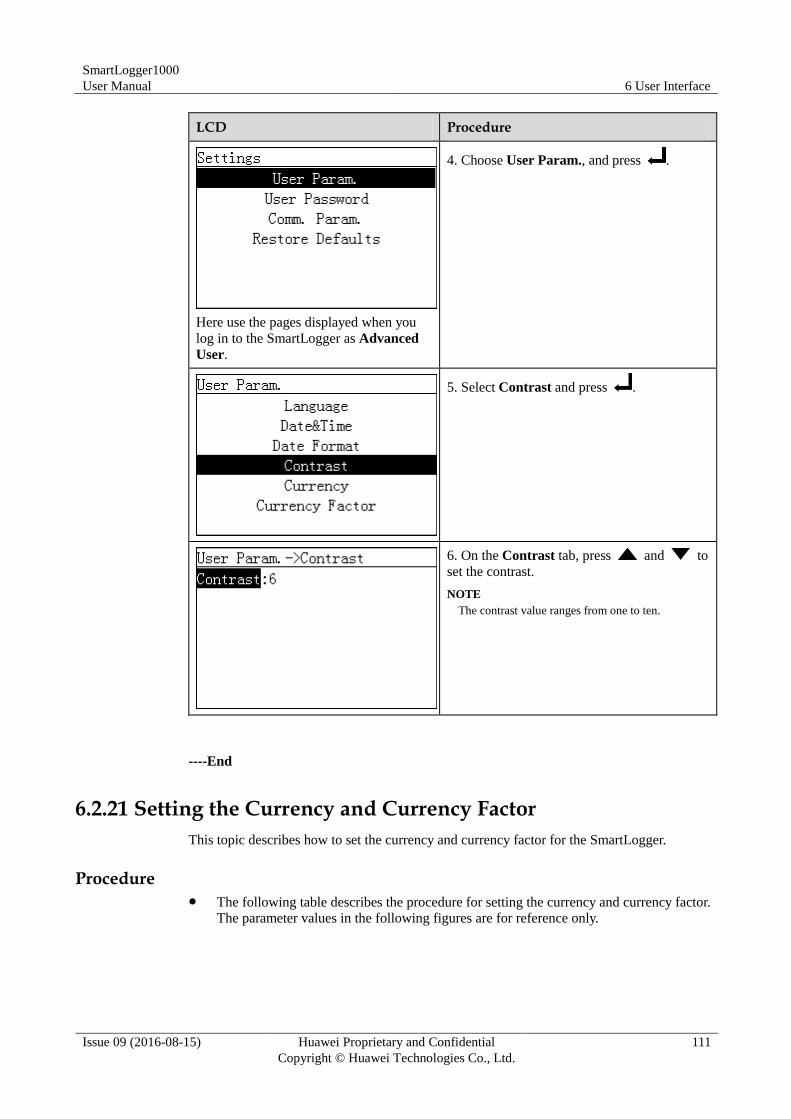
SmartLogger1000
User Manual 6 User Interface
Issue 09 (2016-08-15) Huawei Proprietary and Confidential
Copyright © Huawei Technologies Co., Ltd.
111
LCD Procedure
Here use the pages displayed when you
log in to the SmartLogger as Advanced
User.
4. Choose User Param., and press .
5. Select Contrast and press .
6. On the Contrast tab, press and to
set the contrast.
NOTE
The contrast value ranges from one to ten.
----End
6.2.21 Setting the Currency and Currency Factor
This topic describes how to set the currency and currency factor for the SmartLogger.
Procedure The following table describes the procedure for setting the currency and currency factor.
The parameter values in the following figures are for reference only.
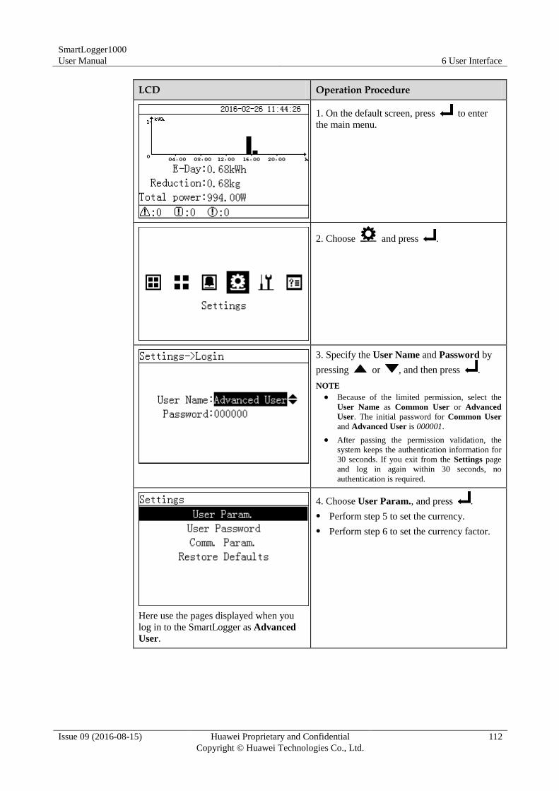
SmartLogger1000
User Manual 6 User Interface
Issue 09 (2016-08-15) Huawei Proprietary and Confidential
Copyright © Huawei Technologies Co., Ltd.
112
LCD Operation Procedure
1. On the default screen, press to enter
the main menu.
2. Choose and press .
3. Specify the User Name and Password by
pressing or , and then press .
NOTE
Because of the limited permission, select the
User Name as Common User or Advanced
User. The initial password for Common User
and Advanced User is 000001.
After passing the permission validation, the
system keeps the authentication information for
30 seconds. If you exit from the Settings page
and log in again within 30 seconds, no
authentication is required.
Here use the pages displayed when you
log in to the SmartLogger as Advanced
User.
4. Choose User Param., and press .
Perform step 5 to set the currency.
Perform step 6 to set the currency factor.
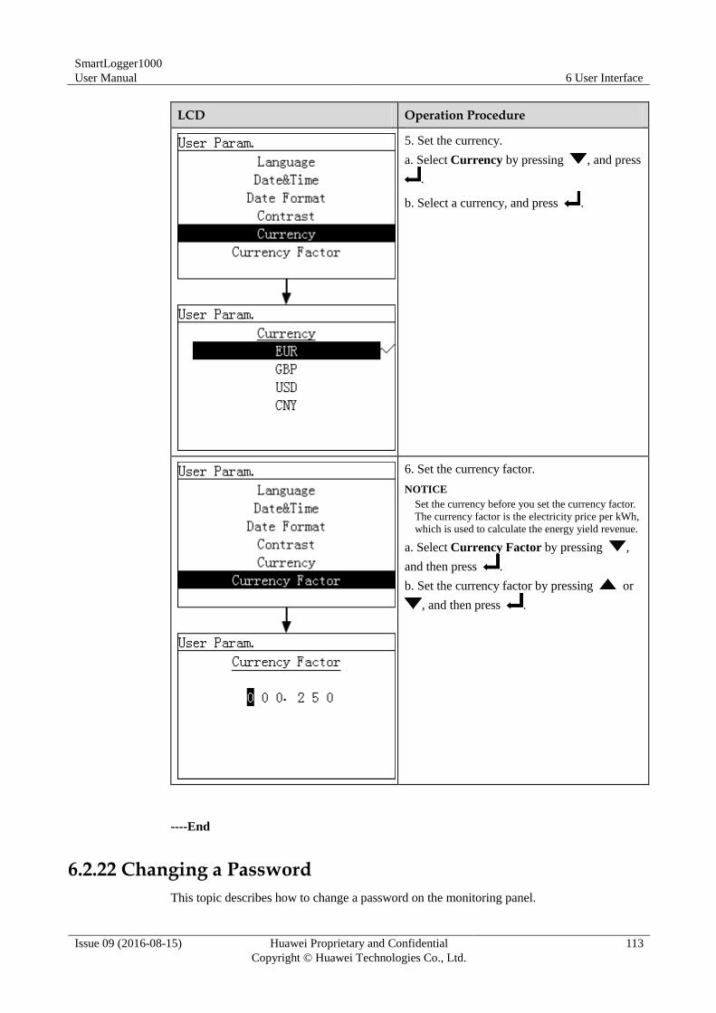
SmartLogger1000
User Manual 6 User Interface
Issue 09 (2016-08-15) Huawei Proprietary and Confidential
Copyright © Huawei Technologies Co., Ltd.
113
LCD Operation Procedure
5. Set the currency.
a. Select Currency by pressing , and press
.
b. Select a currency, and press .
6. Set the currency factor.
NOTICE
Set the currency before you set the currency factor.
The currency factor is the electricity price per kWh,
which is used to calculate the energy yield revenue.
a. Select Currency Factor by pressing ,
and then press .
b. Set the currency factor by pressing or
, and then press .
----End
6.2.22 Changing a Password
This topic describes how to change a password on the monitoring panel.
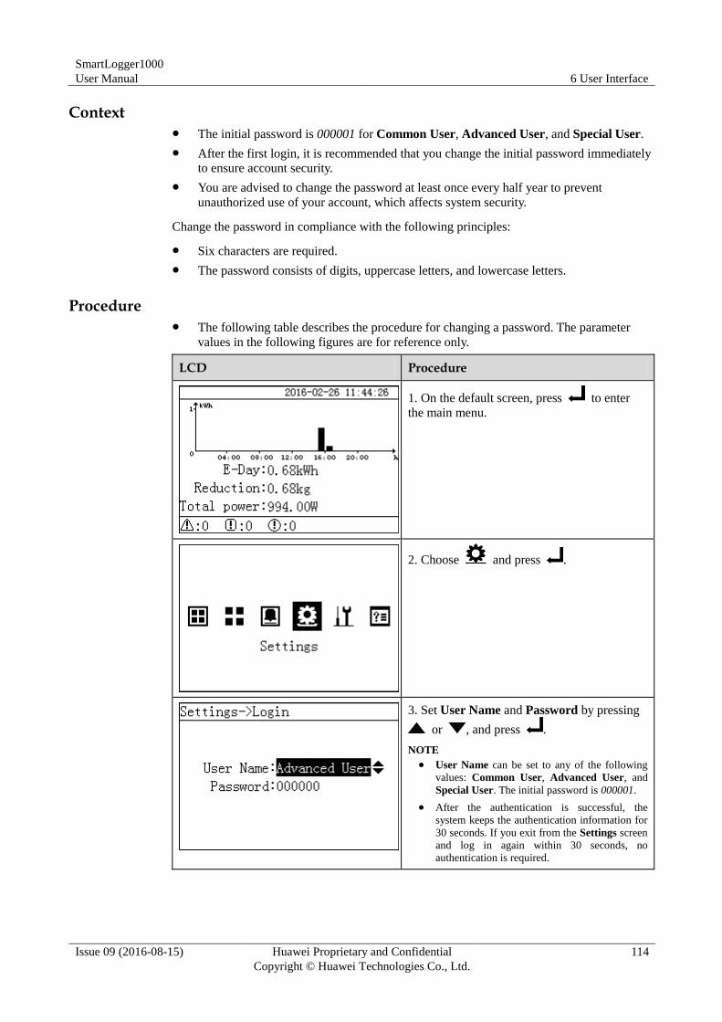
SmartLogger1000
User Manual 6 User Interface
Issue 09 (2016-08-15) Huawei Proprietary and Confidential
Copyright © Huawei Technologies Co., Ltd.
114
Context The initial password is 000001 for Common User, Advanced User, and Special User.
After the first login, it is recommended that you change the initial password immediately
to ensure account security.
You are advised to change the password at least once every half year to prevent
unauthorized use of your account, which affects system security.
Change the password in compliance with the following principles:
Six characters are required.
The password consists of digits, uppercase letters, and lowercase letters.
Procedure The following table describes the procedure for changing a password. The parameter
values in the following figures are for reference only.
LCD Procedure
1. On the default screen, press to enter
the main menu.
2. Choose and press .
3. Set User Name and Password by pressing
or , and press .
NOTE
User Name can be set to any of the following
values: Common User, Advanced User, and
Special User. The initial password is 000001.
After the authentication is successful, the
system keeps the authentication information for
30 seconds. If you exit from the Settings screen
and log in again within 30 seconds, no
authentication is required.
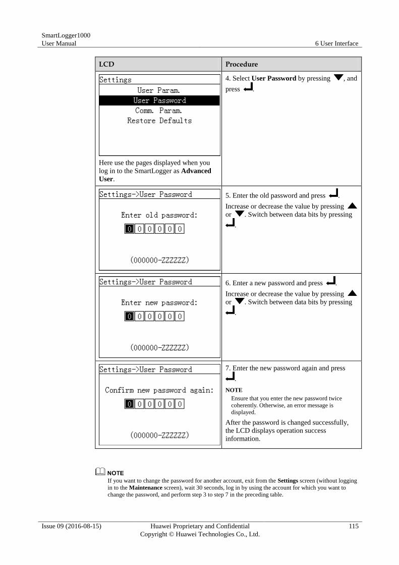
SmartLogger1000
User Manual 6 User Interface
Issue 09 (2016-08-15) Huawei Proprietary and Confidential
Copyright © Huawei Technologies Co., Ltd.
115
LCD Procedure
Here use the pages displayed when you
log in to the SmartLogger as Advanced
User.
4. Select User Password by pressing , and
press .
5. Enter the old password and press .
Increase or decrease the value by pressing
or . Switch between data bits by pressing
.
6. Enter a new password and press .
Increase or decrease the value by pressing
or . Switch between data bits by pressing
.
7. Enter the new password again and press
.
NOTE
Ensure that you enter the new password twice
coherently. Otherwise, an error message is
displayed.
After the password is changed successfully,
the LCD displays operation success
information.
If you want to change the password for another account, exit from the Settings screen (without logging
in to the Maintenance screen), wait 30 seconds, log in by using the account for which you want to
change the password, and perform step 3 to step 7 in the preceding table.
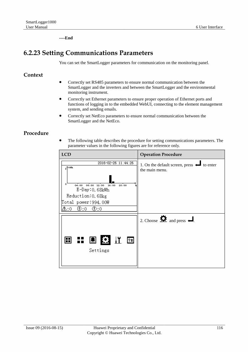
SmartLogger1000
User Manual 6 User Interface
Issue 09 (2016-08-15) Huawei Proprietary and Confidential
Copyright © Huawei Technologies Co., Ltd.
116
----End
6.2.23 Setting Communications Parameters
You can set the SmartLogger parameters for communication on the monitoring panel.
Context Correctly set RS485 parameters to ensure normal communication between the
SmartLogger and the inverters and between the SmartLogger and the environmental
monitoring instrument.
Correctly set Ethernet parameters to ensure proper operation of Ethernet ports and
functions of logging in to the embedded WebUI, connecting to the element management
system, and sending emails.
Correctly set NetEco parameters to ensure normal communication between the
SmartLogger and the NetEco.
Procedure The following table describes the procedure for setting communications parameters. The
parameter values in the following figures are for reference only.
LCD Operation Procedure
1. On the default screen, press to enter
the main menu.
2. Choose and press .
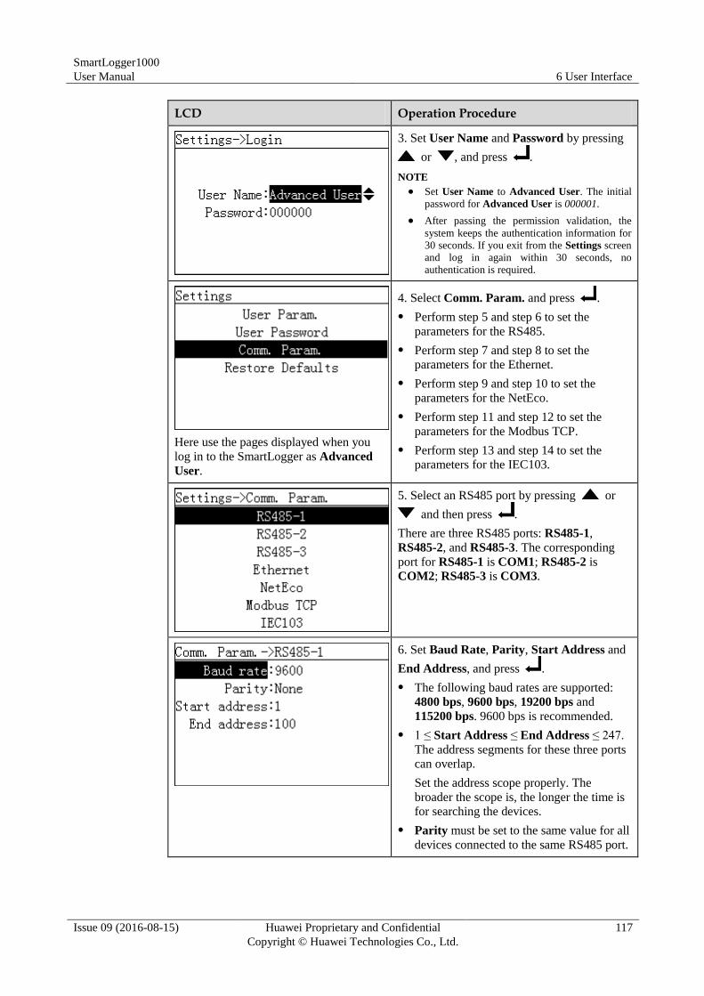
SmartLogger1000
User Manual 6 User Interface
Issue 09 (2016-08-15) Huawei Proprietary and Confidential
Copyright © Huawei Technologies Co., Ltd.
117
LCD Operation Procedure
3. Set User Name and Password by pressing
or , and press .
NOTE
Set User Name to Advanced User. The initial
password for Advanced User is 000001.
After passing the permission validation, the
system keeps the authentication information for
30 seconds. If you exit from the Settings screen
and log in again within 30 seconds, no
authentication is required.
Here use the pages displayed when you
log in to the SmartLogger as Advanced
User.
4. Select Comm. Param. and press .
Perform step 5 and step 6 to set the
parameters for the RS485.
Perform step 7 and step 8 to set the
parameters for the Ethernet.
Perform step 9 and step 10 to set the
parameters for the NetEco.
Perform step 11 and step 12 to set the
parameters for the Modbus TCP.
Perform step 13 and step 14 to set the
parameters for the IEC103.
5. Select an RS485 port by pressing or
and then press .
There are three RS485 ports: RS485-1,
RS485-2, and RS485-3. The corresponding
port for RS485-1 is COM1; RS485-2 is
COM2; RS485-3 is COM3.
6. Set Baud Rate, Parity, Start Address and
End Address, and press .
The following baud rates are supported:
4800 bps, 9600 bps, 19200 bps and
115200 bps. 9600 bps is recommended.
1 ≤ Start Address ≤ End Address ≤ 247.
The address segments for these three ports
can overlap.
Set the address scope properly. The
broader the scope is, the longer the time is
for searching the devices.
Parity must be set to the same value for all
devices connected to the same RS485 port.
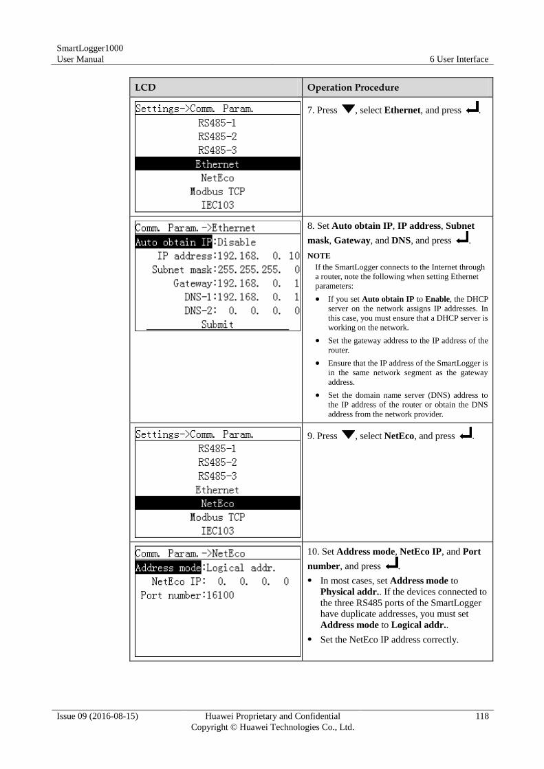
SmartLogger1000
User Manual 6 User Interface
Issue 09 (2016-08-15) Huawei Proprietary and Confidential
Copyright © Huawei Technologies Co., Ltd.
118
LCD Operation Procedure
7. Press , select Ethernet, and press .
8. Set Auto obtain IP, IP address, Subnet
mask, Gateway, and DNS, and press .
NOTE
If the SmartLogger connects to the Internet through
a router, note the following when setting Ethernet
parameters:
If you set Auto obtain IP to Enable, the DHCP
server on the network assigns IP addresses. In
this case, you must ensure that a DHCP server is
working on the network.
Set the gateway address to the IP address of the
router.
Ensure that the IP address of the SmartLogger is
in the same network segment as the gateway
address.
Set the domain name server (DNS) address to
the IP address of the router or obtain the DNS
address from the network provider.
9. Press , select NetEco, and press .
10. Set Address mode, NetEco IP, and Port
number, and press .
In most cases, set Address mode to
Physical addr.. If the devices connected to
the three RS485 ports of the SmartLogger
have duplicate addresses, you must set
Address mode to Logical addr..
Set the NetEco IP address correctly.
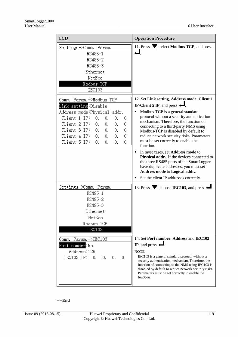
SmartLogger1000
User Manual 6 User Interface
Issue 09 (2016-08-15) Huawei Proprietary and Confidential
Copyright © Huawei Technologies Co., Ltd.
119
LCD Operation Procedure
11. Press , select Modbus TCP, and press
.
12. Set Link setting, Address mode, Client 1
IP-Client 5 IP, and press .
Modbus-TCP is a general standard
protocol without a security authentication
mechanism. Therefore, the function of
connecting to a third-party NMS using
Modbus-TCP is disabled by default to
reduce network security risks. Parameters
must be set correctly to enable the
function.
In most cases, set Address mode to
Physical addr.. If the devices connected to
the three RS485 ports of the SmartLogger
have duplicate addresses, you must set
Address mode to Logical addr..
Set the client IP addresses correctly.
13. Press , choose IEC103, and press .
14. Set Port number, Address and IEC103
IP, and press .
NOTE
IEC103 is a general standard protocol without a
security authentication mechanism. Therefore, the
function of connecting to the NMS using IEC103 is
disabled by default to reduce network security risks.
Parameters must be set correctly to enable the
function.
----End
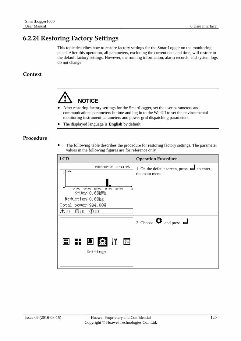
SmartLogger1000
User Manual 6 User Interface
Issue 09 (2016-08-15) Huawei Proprietary and Confidential
Copyright © Huawei Technologies Co., Ltd.
120
6.2.24 Restoring Factory Settings
This topic describes how to restore factory settings for the SmartLogger on the monitoring
panel. After this operation, all parameters, excluding the current date and time, will restore to
the default factory settings. However, the running information, alarm records, and system logs
do not change.
Context
After restoring factory settings for the SmartLogger, set the user parameters and
communications parameters in time and log in to the WebUI to set the environmental
monitoring instrument parameters and power grid dispatching parameters.
The displayed language is English by default.
Procedure The following table describes the procedure for restoring factory settings. The parameter
values in the following figures are for reference only.
LCD Operation Procedure
1. On the default screen, press to enter
the main menu.
2. Choose and press .
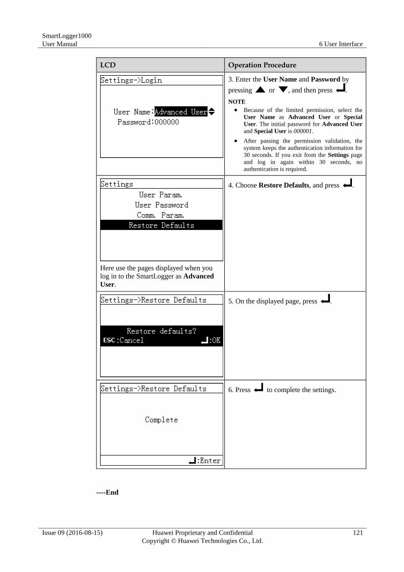
SmartLogger1000
User Manual 6 User Interface
Issue 09 (2016-08-15) Huawei Proprietary and Confidential
Copyright © Huawei Technologies Co., Ltd.
121
LCD Operation Procedure
3. Enter the User Name and Password by
pressing or , and then press .
NOTE
Because of the limited permission, select the
User Name as Advanced User or Special
User. The initial password for Advanced User
and Special User is 000001.
After passing the permission validation, the
system keeps the authentication information for
30 seconds. If you exit from the Settings page
and log in again within 30 seconds, no
authentication is required.
Here use the pages displayed when you
log in to the SmartLogger as Advanced
User.
4. Choose Restore Defaults, and press .
5. On the displayed page, press .
6. Press to complete the settings.
----End
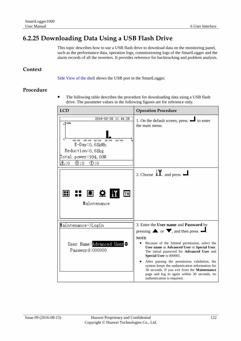
SmartLogger1000
User Manual 6 User Interface
Issue 09 (2016-08-15) Huawei Proprietary and Confidential
Copyright © Huawei Technologies Co., Ltd.
122
6.2.25 Downloading Data Using a USB Flash Drive
This topic describes how to use a USB flash drive to download data on the monitoring panel,
such as the performance data, operation logs, commissioning logs of the SmartLogger and the
alarm records of all the inverters. It provides reference for backtracking and problem analysis.
Context
Side View of the shell shows the USB port in the SmartLogger.
Procedure The following table describes the procedure for downloading data using a USB flash
drive. The parameter values in the following figures are for reference only.
LCD Operation Procedure
1. On the default screen, press to enter
the main menu.
2. Choose and press .
3. Enter the User name and Password by
pressing or , and then press .
NOTE
Because of the limited permission, select the
User name as Advanced User or Special User.
The initial password for Advanced User and
Special User is 000001.
After passing the permission validation, the
system keeps the authentication information for
30 seconds. If you exit from the Maintenance
page and log in again within 30 seconds, no
authentication is required.
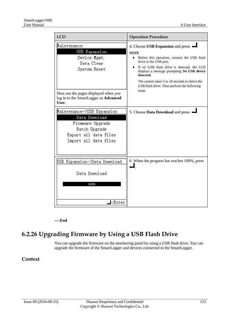
SmartLogger1000
User Manual 6 User Interface
Issue 09 (2016-08-15) Huawei Proprietary and Confidential
Copyright © Huawei Technologies Co., Ltd.
123
LCD Operation Procedure
Here use the pages displayed when you
log in to the SmartLogger as Advanced
User.
4. Choose USB Expansion and press .
NOTE
Before this operation, connect the USB flash
drive to the USB port.
If no USB flash drive is detected, the LCD
displays a message prompting No USB device
detected.
The system takes 5 to 10 seconds to detect the
USB flash drive. Then perform the following
steps.
5. Choose Data Download and press .
6. When the progress bar reaches 100%, press
.
----End
6.2.26 Upgrading Firmware by Using a USB Flash Drive
You can upgrade the firmware on the monitoring panel by using a USB flash drive. You can
upgrade the firmware of the SmartLogger and devices connected to the SmartLogger.
Context
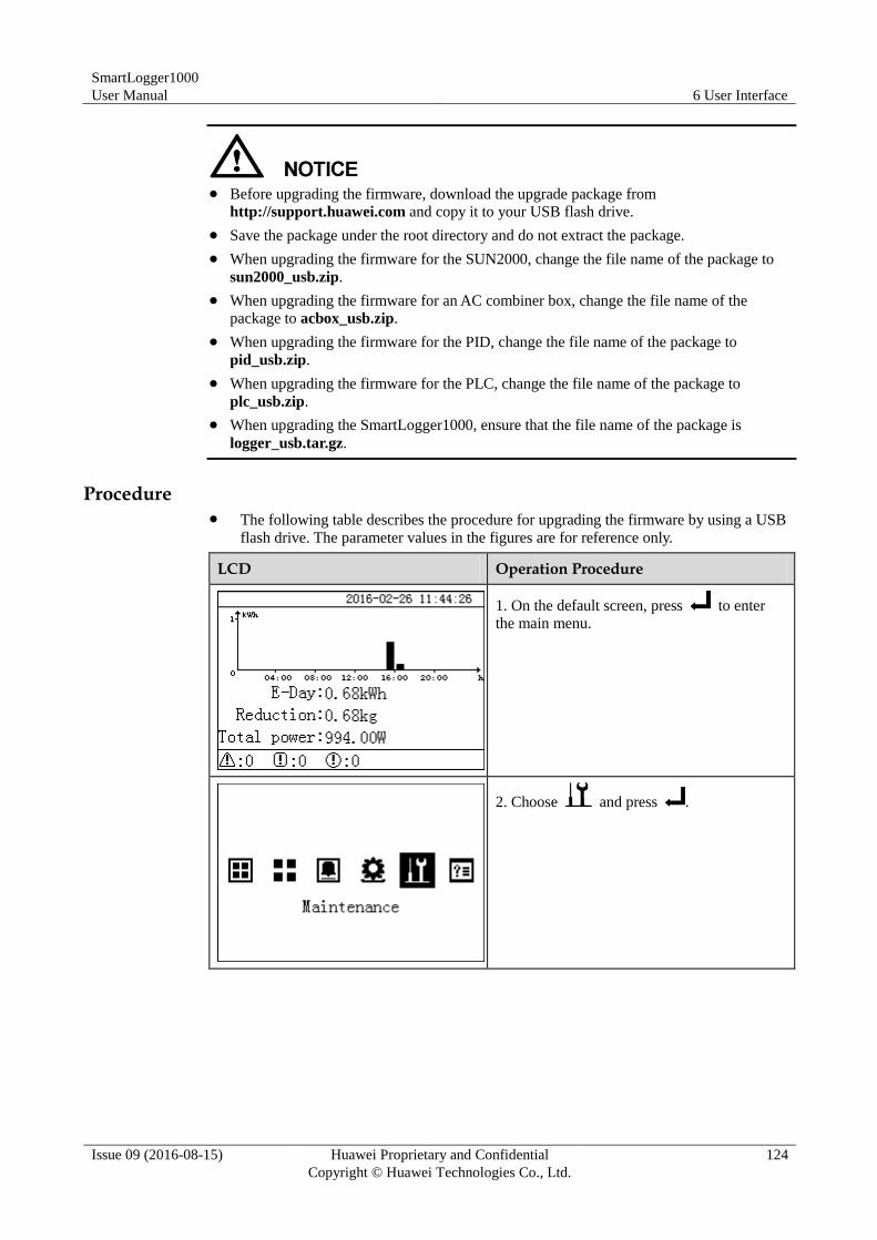
SmartLogger1000
User Manual 6 User Interface
Issue 09 (2016-08-15) Huawei Proprietary and Confidential
Copyright © Huawei Technologies Co., Ltd.
124
Before upgrading the firmware, download the upgrade package from
http://support.huawei.com and copy it to your USB flash drive.
Save the package under the root directory and do not extract the package.
When upgrading the firmware for the SUN2000, change the file name of the package to
sun2000_usb.zip.
When upgrading the firmware for an AC combiner box, change the file name of the
package to acbox_usb.zip.
When upgrading the firmware for the PID, change the file name of the package to
pid_usb.zip.
When upgrading the firmware for the PLC, change the file name of the package to
plc_usb.zip.
When upgrading the SmartLogger1000, ensure that the file name of the package is
logger_usb.tar.gz.
Procedure The following table describes the procedure for upgrading the firmware by using a USB
flash drive. The parameter values in the figures are for reference only.
LCD Operation Procedure
1. On the default screen, press to enter
the main menu.
2. Choose and press .
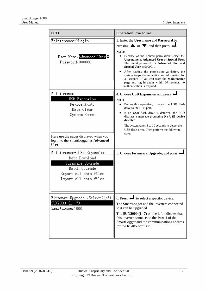
SmartLogger1000
User Manual 6 User Interface
Issue 09 (2016-08-15) Huawei Proprietary and Confidential
Copyright © Huawei Technologies Co., Ltd.
125
LCD Operation Procedure
3. Enter the User name and Password by
pressing or , and then press .
NOTE
Because of the limited permission, select the
User name as Advanced User or Special User.
The initial password for Advanced User and
Special User is 000001.
After passing the permission validation, the
system keeps the authentication information for
30 seconds. If you exit from the Maintenance
page and log in again within 30 seconds, no
authentication is required.
Here use the pages displayed when you
log in to the SmartLogger as Advanced
User.
4. Choose USB Expansion and press .
NOTE
Before this operation, connect the USB flash
drive to the USB port.
If no USB flash drive is detected, the LCD
displays a message prompting No USB device
detected.
The system takes 5 to 10 seconds to detect the
USB flash drive. Then perform the following
steps.
5. Choose Firmware Upgrade, and press .
6. Press to select a specific device.
The SmartLogger and the inverters connected
to it can be upgraded.
The SUN2000 (1--7) on the left indicates that
this inverter connects to the Port 1 of the
SmartLogger and the communications address
for the RS485 port is 7.
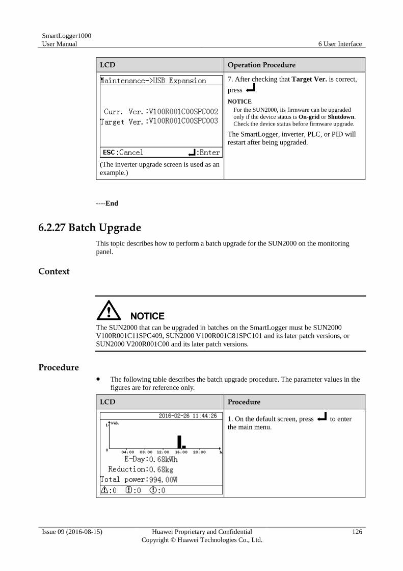
SmartLogger1000
User Manual 6 User Interface
Issue 09 (2016-08-15) Huawei Proprietary and Confidential
Copyright © Huawei Technologies Co., Ltd.
126
LCD Operation Procedure
(The inverter upgrade screen is used as an
example.)
7. After checking that Target Ver. is correct,
press .
NOTICE
For the SUN2000, its firmware can be upgraded
only if the device status is On-grid or Shutdown.
Check the device status before firmware upgrade.
The SmartLogger, inverter, PLC, or PID will
restart after being upgraded.
----End
6.2.27 Batch Upgrade
This topic describes how to perform a batch upgrade for the SUN2000 on the monitoring
panel.
Context
The SUN2000 that can be upgraded in batches on the SmartLogger must be SUN2000
V100R001C11SPC409, SUN2000 V100R001C81SPC101 and its later patch versions, or
SUN2000 V200R001C00 and its later patch versions.
Procedure The following table describes the batch upgrade procedure. The parameter values in the
figures are for reference only.
LCD Procedure
1. On the default screen, press to enter
the main menu.
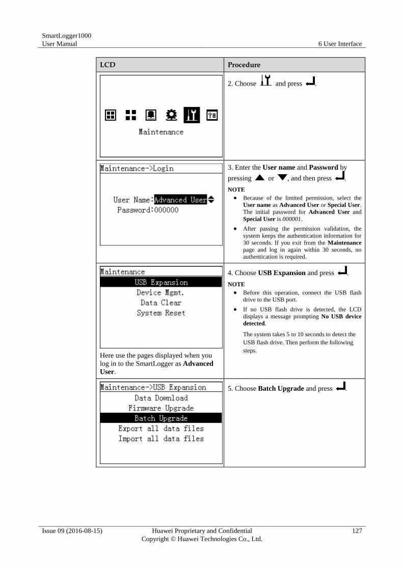
SmartLogger1000
User Manual 6 User Interface
Issue 09 (2016-08-15) Huawei Proprietary and Confidential
Copyright © Huawei Technologies Co., Ltd.
127
LCD Procedure
2. Choose and press .
3. Enter the User name and Password by
pressing or , and then press .
NOTE
Because of the limited permission, select the
User name as Advanced User or Special User.
The initial password for Advanced User and
Special User is 000001.
After passing the permission validation, the
system keeps the authentication information for
30 seconds. If you exit from the Maintenance
page and log in again within 30 seconds, no
authentication is required.
Here use the pages displayed when you
log in to the SmartLogger as Advanced
User.
4. Choose USB Expansion and press .
NOTE
Before this operation, connect the USB flash
drive to the USB port.
If no USB flash drive is detected, the LCD
displays a message prompting No USB device
detected.
The system takes 5 to 10 seconds to detect the
USB flash drive. Then perform the following
steps.
5. Choose Batch Upgrade and press .
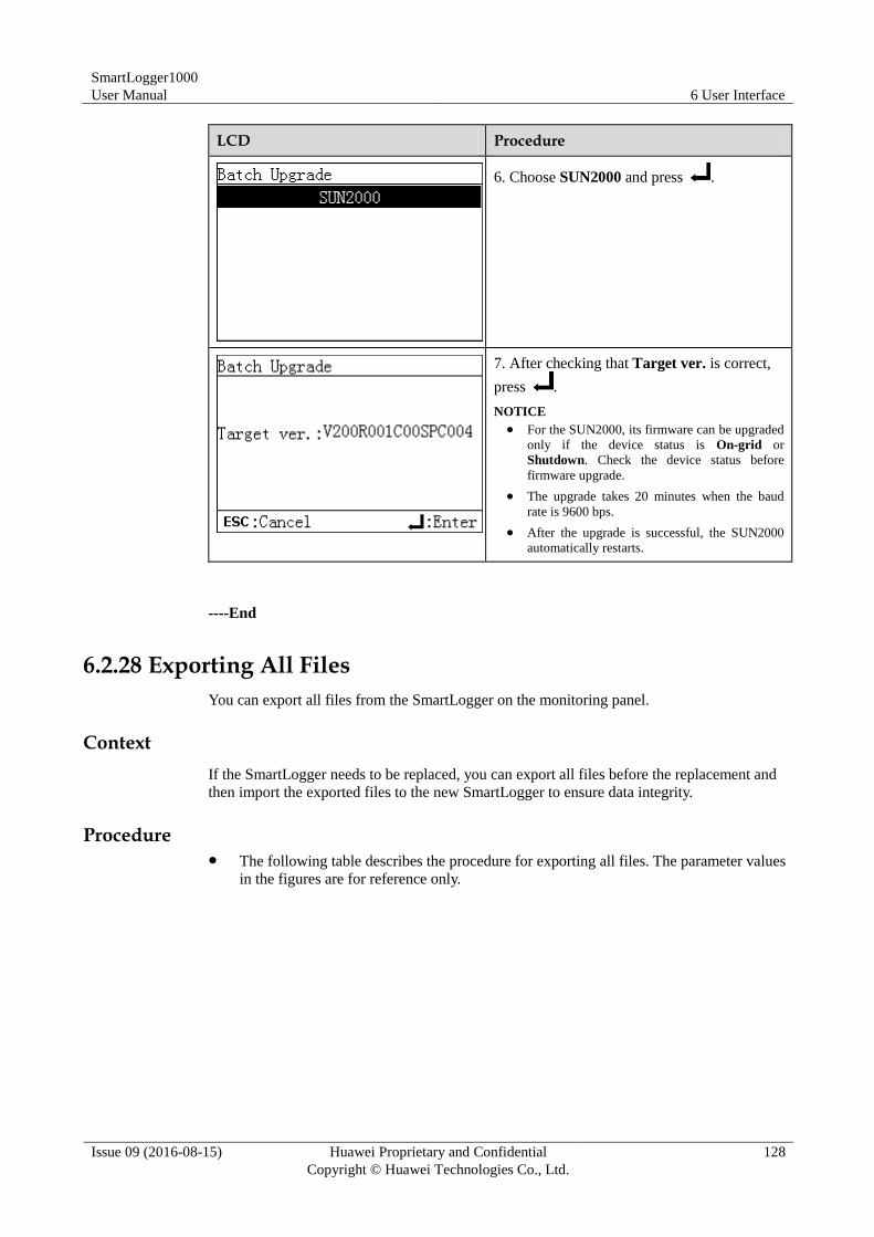
SmartLogger1000
User Manual 6 User Interface
Issue 09 (2016-08-15) Huawei Proprietary and Confidential
Copyright © Huawei Technologies Co., Ltd.
128
LCD Procedure
6. Choose SUN2000 and press .
7. After checking that Target ver. is correct,
press .
NOTICE
For the SUN2000, its firmware can be upgraded
only if the device status is On-grid or
Shutdown. Check the device status before
firmware upgrade.
The upgrade takes 20 minutes when the baud
rate is 9600 bps.
After the upgrade is successful, the SUN2000
automatically restarts.
----End
6.2.28 Exporting All Files
You can export all files from the SmartLogger on the monitoring panel.
Context
If the SmartLogger needs to be replaced, you can export all files before the replacement and
then import the exported files to the new SmartLogger to ensure data integrity.
Procedure The following table describes the procedure for exporting all files. The parameter values
in the figures are for reference only.
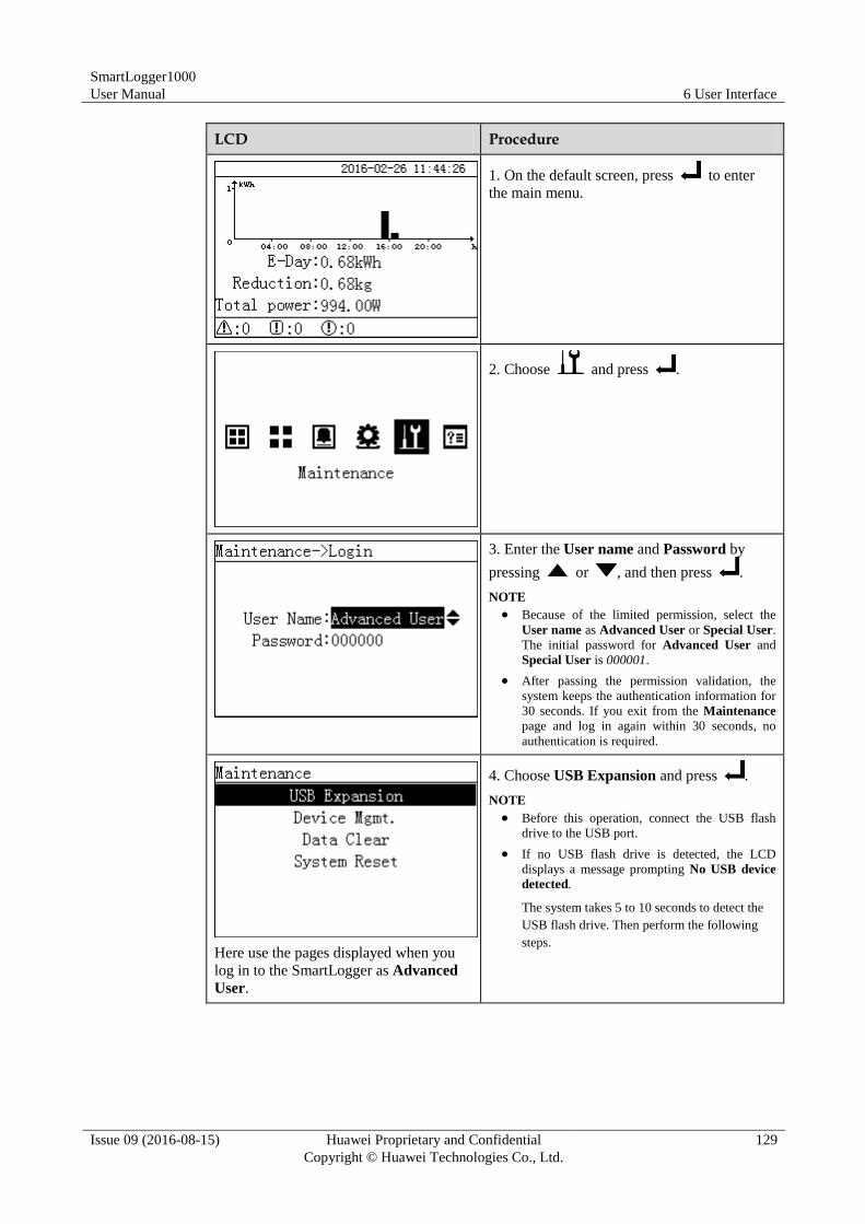
SmartLogger1000
User Manual 6 User Interface
Issue 09 (2016-08-15) Huawei Proprietary and Confidential
Copyright © Huawei Technologies Co., Ltd.
129
LCD Procedure
1. On the default screen, press to enter
the main menu.
2. Choose and press .
3. Enter the User name and Password by
pressing or , and then press .
NOTE
Because of the limited permission, select the
User name as Advanced User or Special User.
The initial password for Advanced User and
Special User is 000001.
After passing the permission validation, the
system keeps the authentication information for
30 seconds. If you exit from the Maintenance
page and log in again within 30 seconds, no
authentication is required.
Here use the pages displayed when you
log in to the SmartLogger as Advanced
User.
4. Choose USB Expansion and press .
NOTE
Before this operation, connect the USB flash
drive to the USB port.
If no USB flash drive is detected, the LCD
displays a message prompting No USB device
detected.
The system takes 5 to 10 seconds to detect the
USB flash drive. Then perform the following
steps.
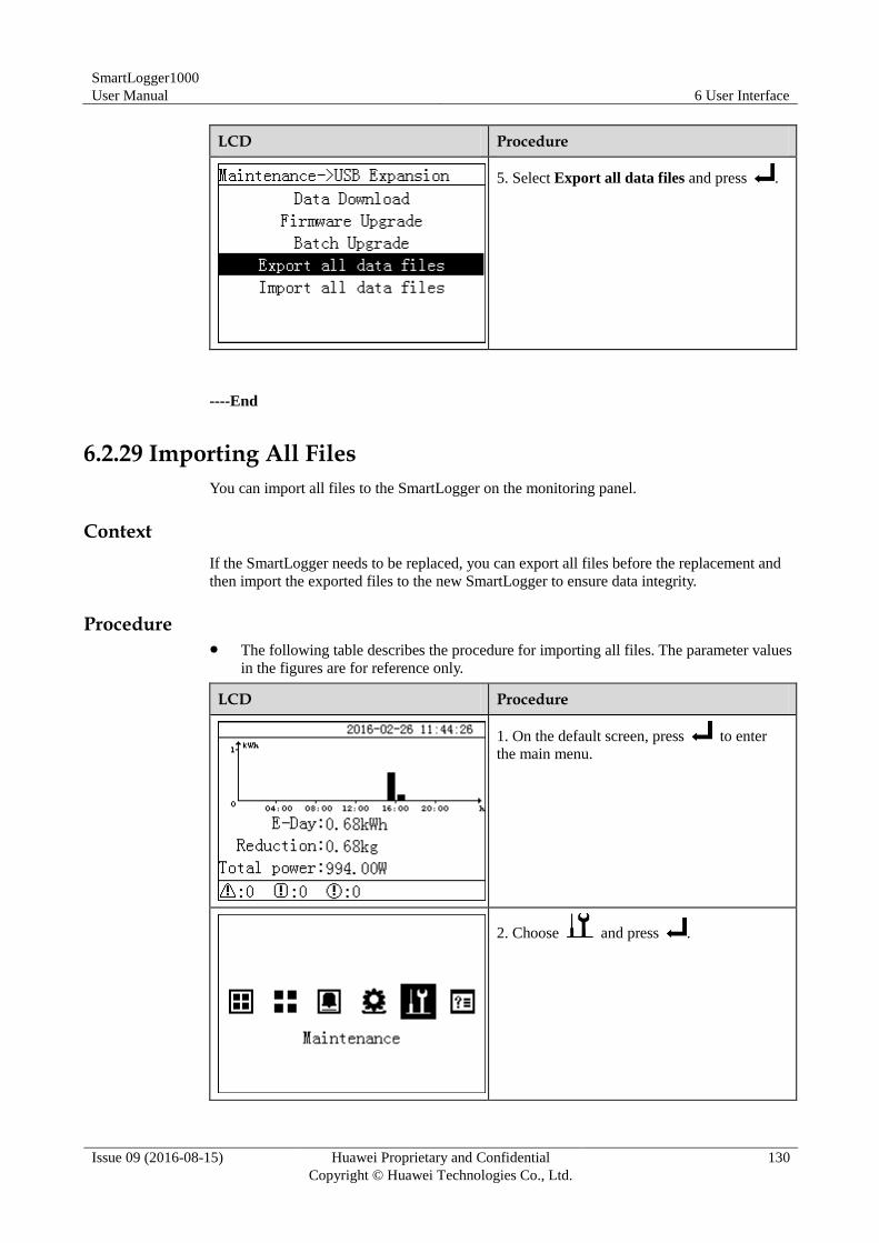
SmartLogger1000
User Manual 6 User Interface
Issue 09 (2016-08-15) Huawei Proprietary and Confidential
Copyright © Huawei Technologies Co., Ltd.
130
LCD Procedure
5. Select Export all data files and press .
----End
6.2.29 Importing All Files
You can import all files to the SmartLogger on the monitoring panel.
Context
If the SmartLogger needs to be replaced, you can export all files before the replacement and
then import the exported files to the new SmartLogger to ensure data integrity.
Procedure The following table describes the procedure for importing all files. The parameter values
in the figures are for reference only.
LCD Procedure
1. On the default screen, press to enter
the main menu.
2. Choose and press .
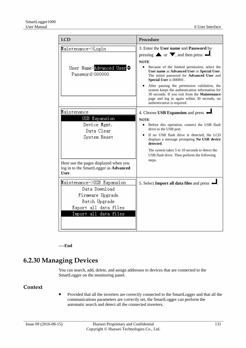
SmartLogger1000
User Manual 6 User Interface
Issue 09 (2016-08-15) Huawei Proprietary and Confidential
Copyright © Huawei Technologies Co., Ltd.
131
LCD Procedure
3. Enter the User name and Password by
pressing or , and then press .
NOTE
Because of the limited permission, select the
User name as Advanced User or Special User.
The initial password for Advanced User and
Special User is 000001.
After passing the permission validation, the
system keeps the authentication information for
30 seconds. If you exit from the Maintenance
page and log in again within 30 seconds, no
authentication is required.
Here use the pages displayed when you
log in to the SmartLogger as Advanced
User.
4. Choose USB Expansion and press .
NOTE
Before this operation, connect the USB flash
drive to the USB port.
If no USB flash drive is detected, the LCD
displays a message prompting No USB device
detected.
The system takes 5 to 10 seconds to detect the
USB flash drive. Then perform the following
steps.
5. Select Import all data files and press .
----End
6.2.30 Managing Devices
You can search, add, delete, and assign addresses to devices that are connected to the
SmartLogger on the monitoring panel.
Context Provided that all the inverters are correctly connected to the SmartLogger and that all the
communications parameters are correctly set, the SmartLogger can perform the
automatic search and detect all the connected inverters.
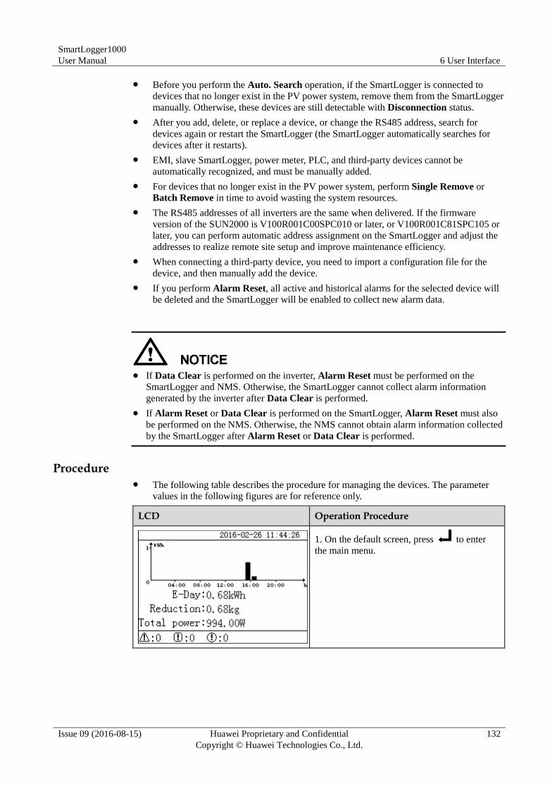
SmartLogger1000
User Manual 6 User Interface
Issue 09 (2016-08-15) Huawei Proprietary and Confidential
Copyright © Huawei Technologies Co., Ltd.
132
Before you perform the Auto. Search operation, if the SmartLogger is connected to
devices that no longer exist in the PV power system, remove them from the SmartLogger
manually. Otherwise, these devices are still detectable with Disconnection status.
After you add, delete, or replace a device, or change the RS485 address, search for
devices again or restart the SmartLogger (the SmartLogger automatically searches for
devices after it restarts).
EMI, slave SmartLogger, power meter, PLC, and third-party devices cannot be
automatically recognized, and must be manually added.
For devices that no longer exist in the PV power system, perform Single Remove or
Batch Remove in time to avoid wasting the system resources.
The RS485 addresses of all inverters are the same when delivered. If the firmware
version of the SUN2000 is V100R001C00SPC010 or later, or V100R001C81SPC105 or
later, you can perform automatic address assignment on the SmartLogger and adjust the
addresses to realize remote site setup and improve maintenance efficiency.
When connecting a third-party device, you need to import a configuration file for the
device, and then manually add the device.
If you perform Alarm Reset, all active and historical alarms for the selected device will
be deleted and the SmartLogger will be enabled to collect new alarm data.
If Data Clear is performed on the inverter, Alarm Reset must be performed on the
SmartLogger and NMS. Otherwise, the SmartLogger cannot collect alarm information
generated by the inverter after Data Clear is performed.
If Alarm Reset or Data Clear is performed on the SmartLogger, Alarm Reset must also
be performed on the NMS. Otherwise, the NMS cannot obtain alarm information collected
by the SmartLogger after Alarm Reset or Data Clear is performed.
Procedure The following table describes the procedure for managing the devices. The parameter
values in the following figures are for reference only.
LCD Operation Procedure
1. On the default screen, press to enter
the main menu.
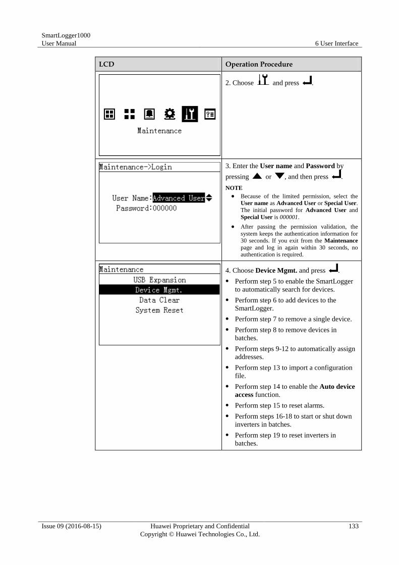
SmartLogger1000
User Manual 6 User Interface
Issue 09 (2016-08-15) Huawei Proprietary and Confidential
Copyright © Huawei Technologies Co., Ltd.
133
LCD Operation Procedure
2. Choose and press .
3. Enter the User name and Password by
pressing or , and then press .
NOTE
Because of the limited permission, select the
User name as Advanced User or Special User.
The initial password for Advanced User and
Special User is 000001.
After passing the permission validation, the
system keeps the authentication information for
30 seconds. If you exit from the Maintenance
page and log in again within 30 seconds, no
authentication is required.
4. Choose Device Mgmt. and press .
Perform step 5 to enable the SmartLogger
to automatically search for devices.
Perform step 6 to add devices to the
SmartLogger.
Perform step 7 to remove a single device.
Perform step 8 to remove devices in
batches.
Perform steps 9-12 to automatically assign
addresses.
Perform step 13 to import a configuration
file.
Perform step 14 to enable the Auto device
access function.
Perform step 15 to reset alarms.
Perform steps 16-18 to start or shut down
inverters in batches.
Perform step 19 to reset inverters in
batches.
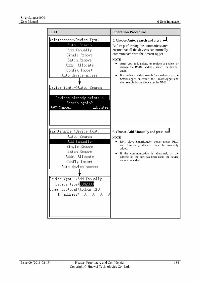
SmartLogger1000
User Manual 6 User Interface
Issue 09 (2016-08-15) Huawei Proprietary and Confidential
Copyright © Huawei Technologies Co., Ltd.
134
LCD Operation Procedure
5. Choose Auto. Search and press .
Before performing the automatic search,
ensure that all the devices can normally
communicate with the SmartLogger.
NOTE
After you add, delete, or replace a device, or
change the RS485 address, search for devices
again.
If a device is added, search for the device on the
SmartLogger or restart the SmartLogger and
then search for the device on the NMS.
6. Choose Add Manually and press .
NOTE
EMI, slave SmartLogger, power meter, PLC,
and third-party devices must be manually
added.
If the communication is abnormal, or the
address on the port has been used, the device
cannot be added.
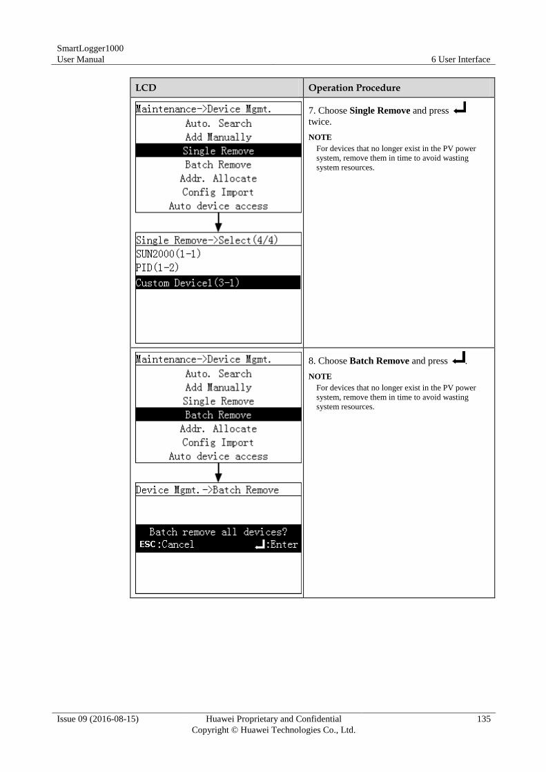
SmartLogger1000
User Manual 6 User Interface
Issue 09 (2016-08-15) Huawei Proprietary and Confidential
Copyright © Huawei Technologies Co., Ltd.
135
LCD Operation Procedure
7. Choose Single Remove and press
twice.
NOTE
For devices that no longer exist in the PV power
system, remove them in time to avoid wasting
system resources.
8. Choose Batch Remove and press .
NOTE
For devices that no longer exist in the PV power
system, remove them in time to avoid wasting
system resources.
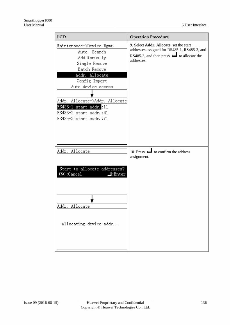
SmartLogger1000
User Manual 6 User Interface
Issue 09 (2016-08-15) Huawei Proprietary and Confidential
Copyright © Huawei Technologies Co., Ltd.
136
LCD Operation Procedure
9. Select Addr. Allocate, set the start
addresses assigned for RS485-1, RS485-2, and
RS485-3, and then press to allocate the
addresses.
10. Press to confirm the address
assignment.
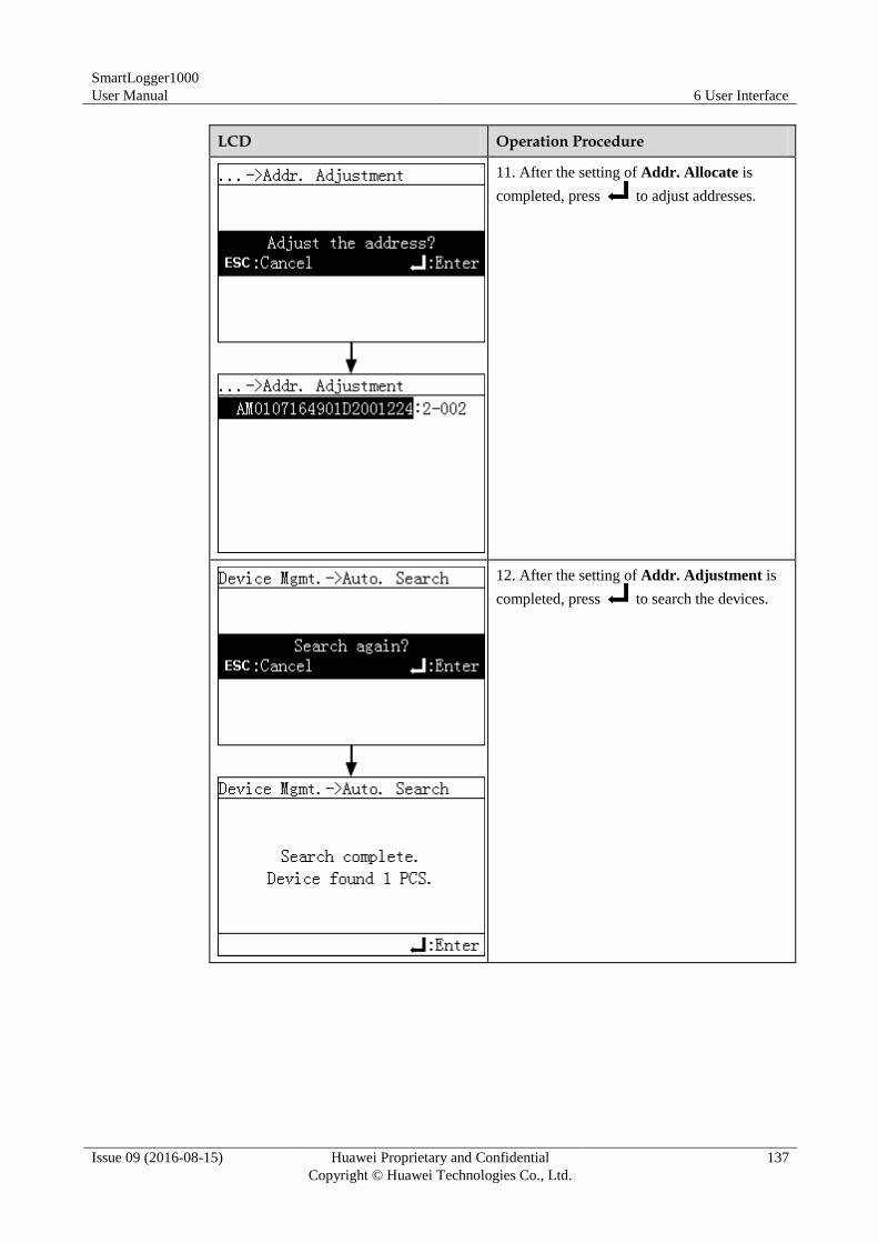
SmartLogger1000
User Manual 6 User Interface
Issue 09 (2016-08-15) Huawei Proprietary and Confidential
Copyright © Huawei Technologies Co., Ltd.
137
LCD Operation Procedure
11. After the setting of Addr. Allocate is
completed, press to adjust addresses.
12. After the setting of Addr. Adjustment is
completed, press to search the devices.
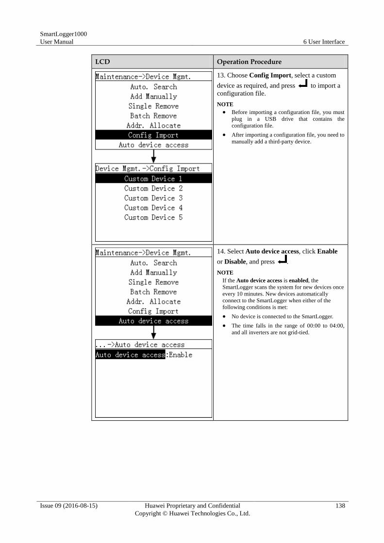
SmartLogger1000
User Manual 6 User Interface
Issue 09 (2016-08-15) Huawei Proprietary and Confidential
Copyright © Huawei Technologies Co., Ltd.
138
LCD Operation Procedure
13. Choose Config Import, select a custom
device as required, and press to import a
configuration file.
NOTE
Before importing a configuration file, you must
plug in a USB drive that contains the
configuration file.
After importing a configuration file, you need to
manually add a third-party device.
14. Select Auto device access, click Enable
or Disable, and press .
NOTE
If the Auto device access is enabled, the
SmartLogger scans the system for new devices once
every 10 minutes. New devices automatically
connect to the SmartLogger when either of the
following conditions is met:
No device is connected to the SmartLogger.
The time falls in the range of 00:00 to 04:00,
and all inverters are not grid-tied.
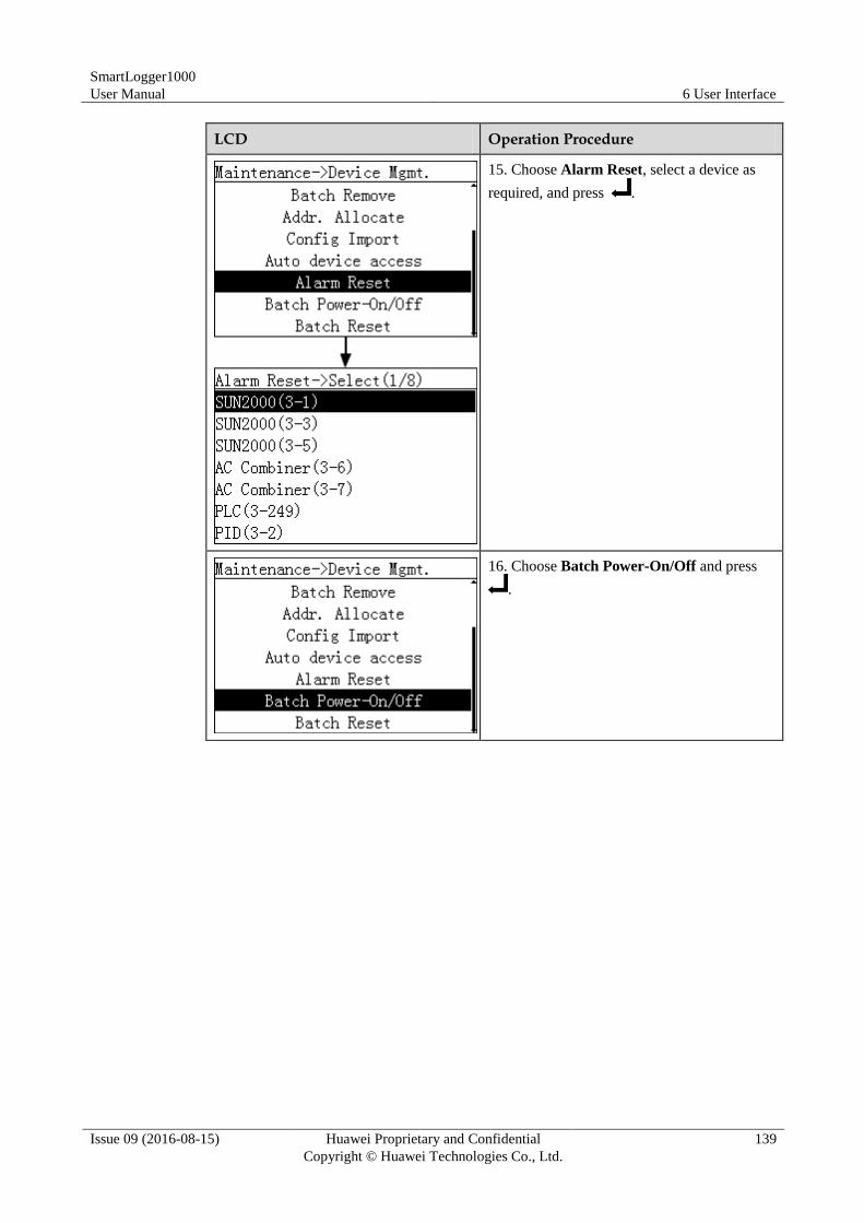
SmartLogger1000
User Manual 6 User Interface
Issue 09 (2016-08-15) Huawei Proprietary and Confidential
Copyright © Huawei Technologies Co., Ltd.
139
LCD Operation Procedure
15. Choose Alarm Reset, select a device as
required, and press .
16. Choose Batch Power-On/Off and press
.
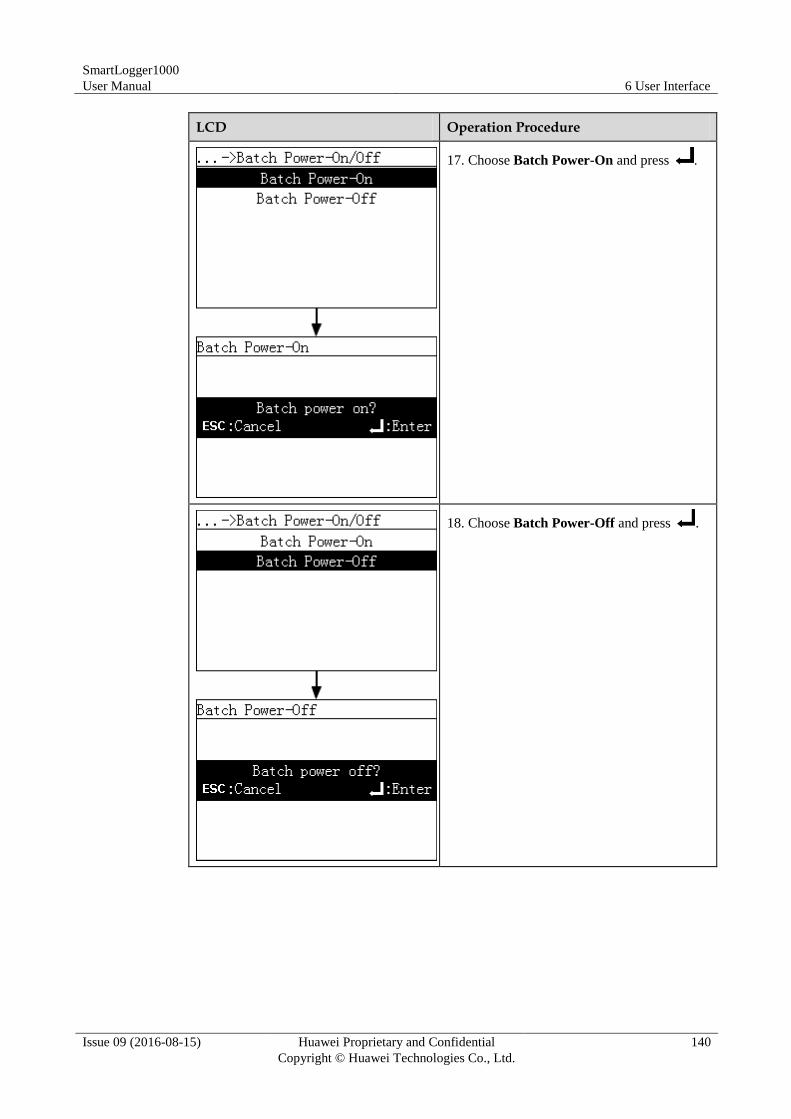
SmartLogger1000
User Manual 6 User Interface
Issue 09 (2016-08-15) Huawei Proprietary and Confidential
Copyright © Huawei Technologies Co., Ltd.
140
LCD Operation Procedure
17. Choose Batch Power-On and press .
18. Choose Batch Power-Off and press .
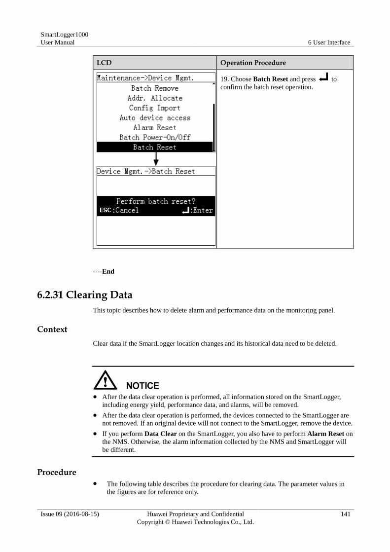
SmartLogger1000
User Manual 6 User Interface
Issue 09 (2016-08-15) Huawei Proprietary and Confidential
Copyright © Huawei Technologies Co., Ltd.
141
LCD Operation Procedure
19. Choose Batch Reset and press to
confirm the batch reset operation.
----End
6.2.31 Clearing Data
This topic describes how to delete alarm and performance data on the monitoring panel.
Context
Clear data if the SmartLogger location changes and its historical data need to be deleted.
After the data clear operation is performed, all information stored on the SmartLogger,
including energy yield, performance data, and alarms, will be removed.
After the data clear operation is performed, the devices connected to the SmartLogger are
not removed. If an original device will not connect to the SmartLogger, remove the device.
If you perform Data Clear on the SmartLogger, you also have to perform Alarm Reset on
the NMS. Otherwise, the alarm information collected by the NMS and SmartLogger will
be different.
Procedure The following table describes the procedure for clearing data. The parameter values in
the figures are for reference only.
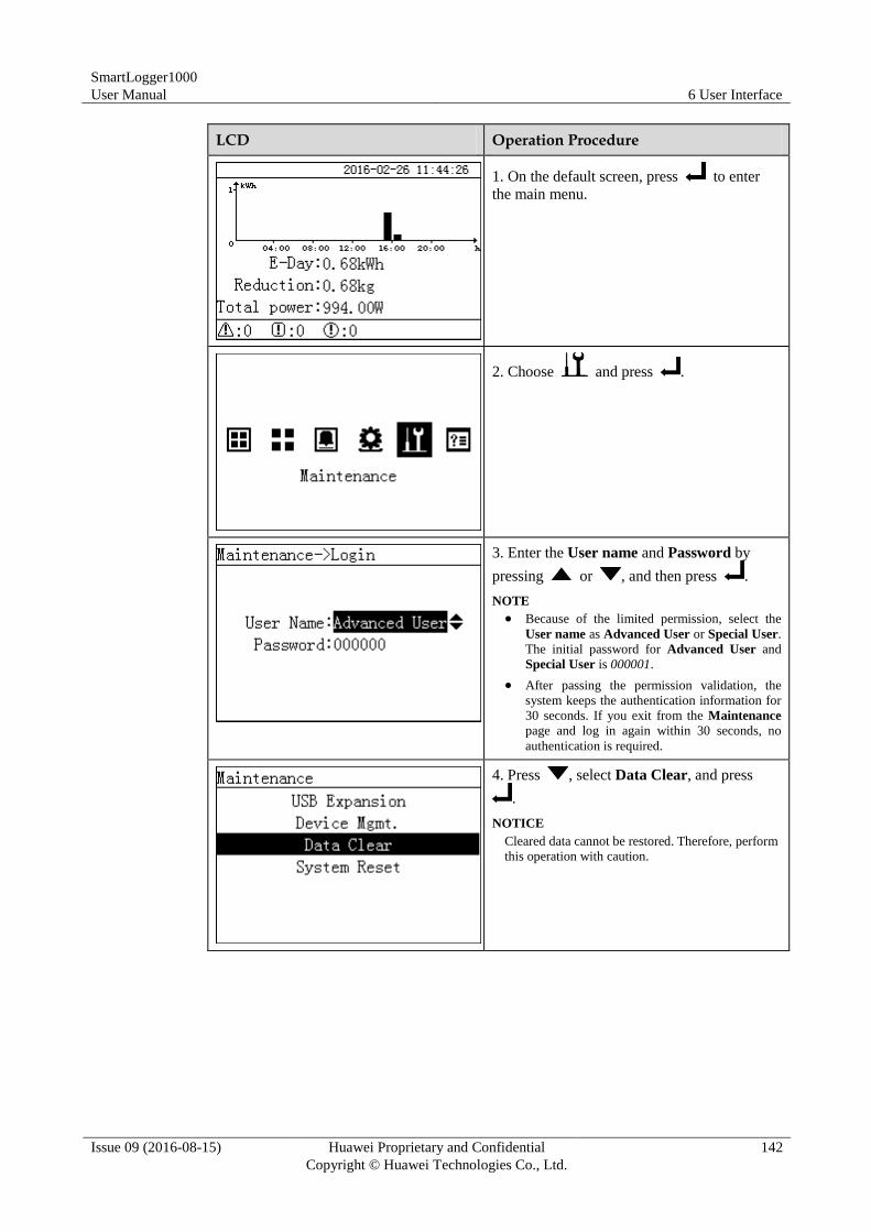
SmartLogger1000
User Manual 6 User Interface
Issue 09 (2016-08-15) Huawei Proprietary and Confidential
Copyright © Huawei Technologies Co., Ltd.
142
LCD Operation Procedure
1. On the default screen, press to enter
the main menu.
2. Choose and press .
3. Enter the User name and Password by
pressing or , and then press .
NOTE
Because of the limited permission, select the
User name as Advanced User or Special User.
The initial password for Advanced User and
Special User is 000001.
After passing the permission validation, the
system keeps the authentication information for
30 seconds. If you exit from the Maintenance
page and log in again within 30 seconds, no
authentication is required.
4. Press , select Data Clear, and press
.
NOTICE
Cleared data cannot be restored. Therefore, perform
this operation with caution.
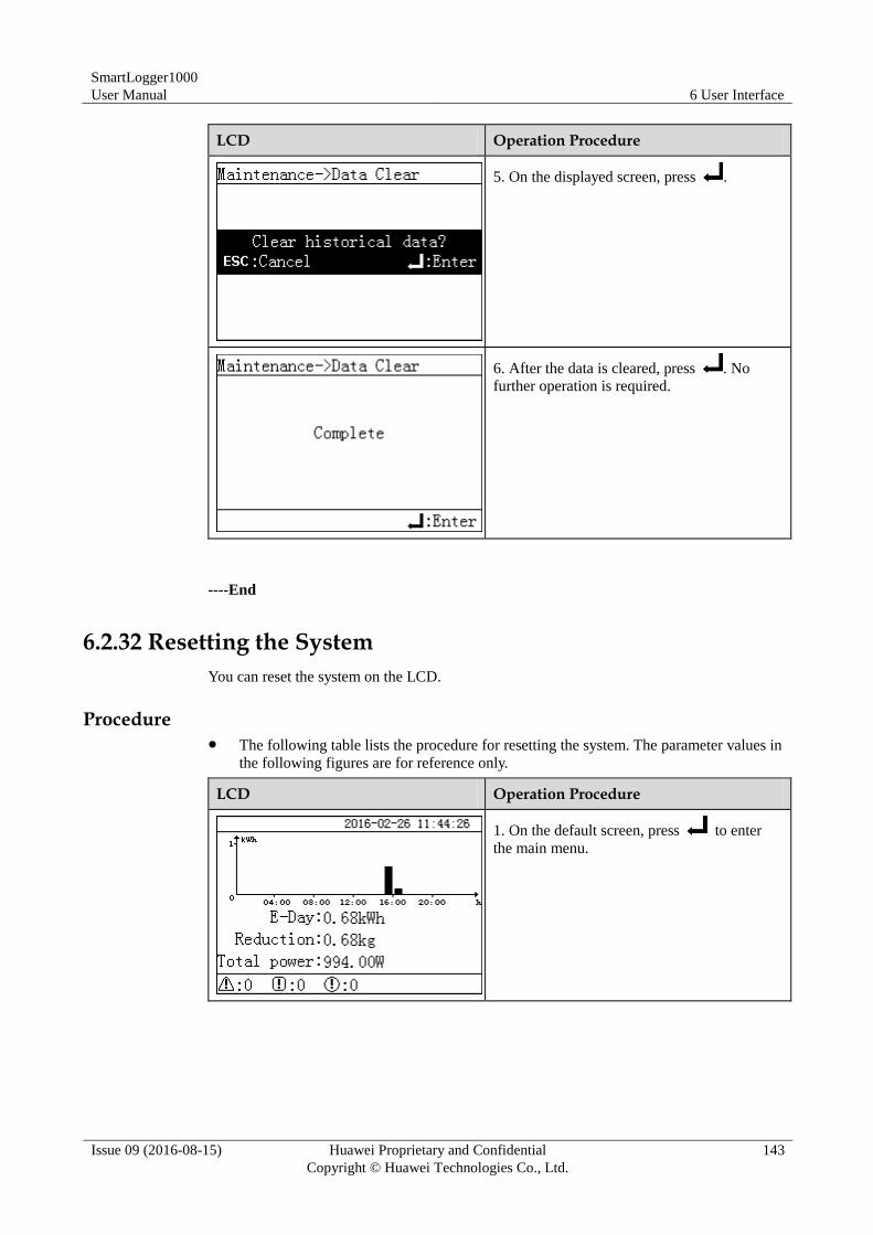
SmartLogger1000
User Manual 6 User Interface
Issue 09 (2016-08-15) Huawei Proprietary and Confidential
Copyright © Huawei Technologies Co., Ltd.
143
LCD Operation Procedure
5. On the displayed screen, press .
6. After the data is cleared, press . No
further operation is required.
----End
6.2.32 Resetting the System
You can reset the system on the LCD.
Procedure The following table lists the procedure for resetting the system. The parameter values in
the following figures are for reference only.
LCD Operation Procedure
1. On the default screen, press to enter
the main menu.
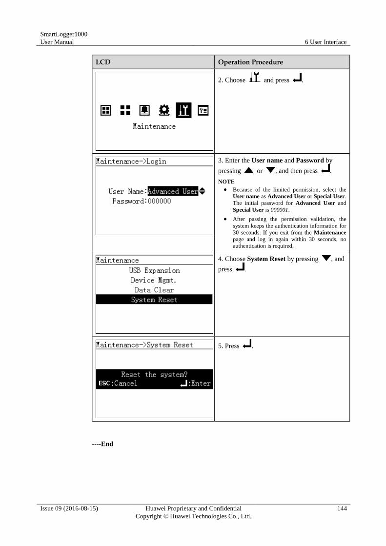
SmartLogger1000
User Manual 6 User Interface
Issue 09 (2016-08-15) Huawei Proprietary and Confidential
Copyright © Huawei Technologies Co., Ltd.
144
LCD Operation Procedure
2. Choose and press .
3. Enter the User name and Password by
pressing or , and then press .
NOTE
Because of the limited permission, select the
User name as Advanced User or Special User.
The initial password for Advanced User and
Special User is 000001.
After passing the permission validation, the
system keeps the authentication information for
30 seconds. If you exit from the Maintenance
page and log in again within 30 seconds, no
authentication is required.
4. Choose System Reset by pressing , and
press .
5. Press .
----End
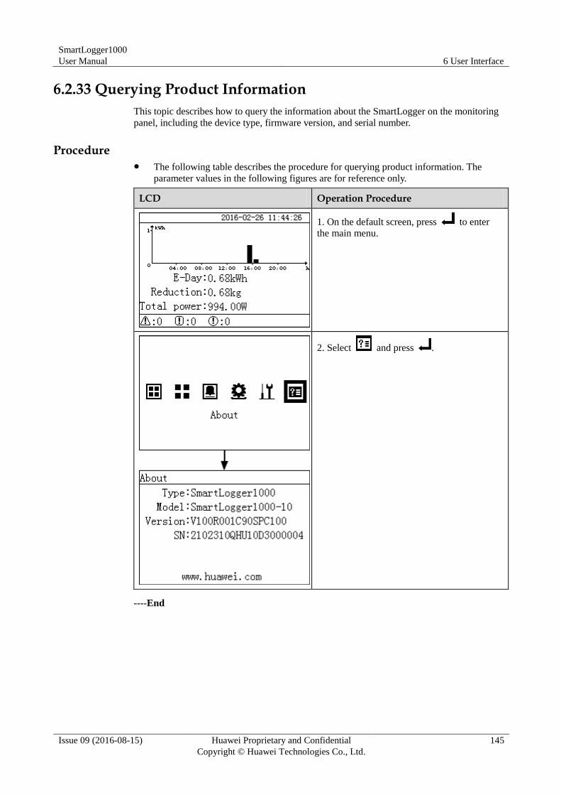
SmartLogger1000
User Manual 6 User Interface
Issue 09 (2016-08-15) Huawei Proprietary and Confidential
Copyright © Huawei Technologies Co., Ltd.
145
6.2.33 Querying Product Information
This topic describes how to query the information about the SmartLogger on the monitoring
panel, including the device type, firmware version, and serial number.
Procedure The following table describes the procedure for querying product information. The
parameter values in the following figures are for reference only.
LCD Operation Procedure
1. On the default screen, press to enter
the main menu.
2. Select and press .
----End
SmartLogger1000
User Manual 7 Web User Interface
Issue 09 (2016-08-15) Huawei Proprietary and Confidential
Copyright © Huawei Technologies Co., Ltd.
146
7 Web User Interface
This topic describes how to log in to the Web user interface (WebUI) and the WEB menu, and
set parameters and maintain devices on the WebUI.
Context
Figures provided in this chapter correspond to the SUN2000 V100R001C95SPC108 version.
The data in the figures provided in this document are for reference only.
7.1 Preparations for Login
Operating Environment
The running environment for the WebUI should meet the following requirements:
Operating system: Windows.
Browser: Internet Explorer 8 to Internet Explorer 11, Firefox17 to Firefox39, and
CHROME41 to CHROME45 (Windows 7).
Minimum resolution: 1024 x 768.
For Internet Explorer 8.0, the recommended release is 8.0.7601.17514 or later.
For Internet Explorer 10, the compatible mode is recommended.
Setting the IP Address
Correctly set the IP address, subnet mask, and gateway for the SmartLogger, PC, and network
devices.
Setting the LAN
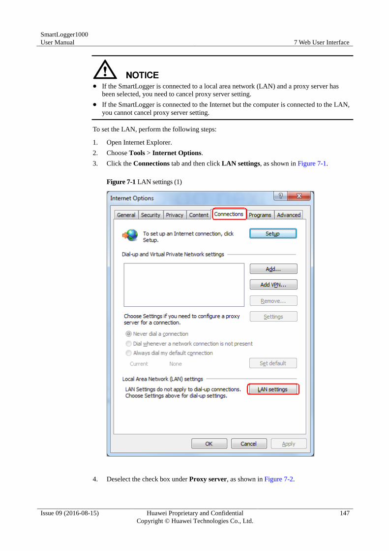
SmartLogger1000
User Manual 7 Web User Interface
Issue 09 (2016-08-15) Huawei Proprietary and Confidential
Copyright © Huawei Technologies Co., Ltd.
147
If the SmartLogger is connected to a local area network (LAN) and a proxy server has
been selected, you need to cancel proxy server setting.
If the SmartLogger is connected to the Internet but the computer is connected to the LAN,
you cannot cancel proxy server setting.
To set the LAN, perform the following steps:
1. Open Internet Explorer.
2. Choose Tools > Internet Options.
3. Click the Connections tab and then click LAN settings, as shown in Figure 7-1.
Figure 7-1 LAN settings (1)
4. Deselect the check box under Proxy server, as shown in Figure 7-2.
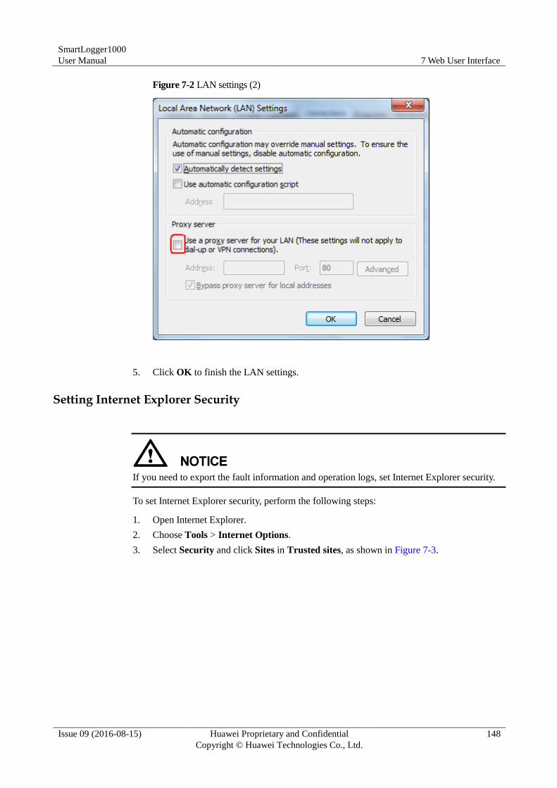
SmartLogger1000
User Manual 7 Web User Interface
Issue 09 (2016-08-15) Huawei Proprietary and Confidential
Copyright © Huawei Technologies Co., Ltd.
148
Figure 7-2 LAN settings (2)
5. Click OK to finish the LAN settings.
Setting Internet Explorer Security
If you need to export the fault information and operation logs, set Internet Explorer security.
To set Internet Explorer security, perform the following steps:
1. Open Internet Explorer.
2. Choose Tools > Internet Options.
3. Select Security and click Sites in Trusted sites, as shown in Figure 7-3.
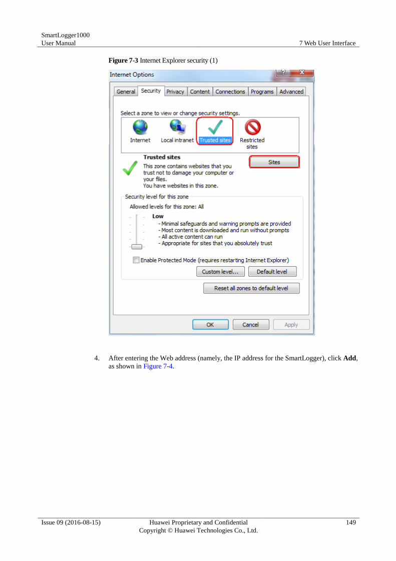
SmartLogger1000
User Manual 7 Web User Interface
Issue 09 (2016-08-15) Huawei Proprietary and Confidential
Copyright © Huawei Technologies Co., Ltd.
149
Figure 7-3 Internet Explorer security (1)
4. After entering the Web address (namely, the IP address for the SmartLogger), click Add,
as shown in Figure 7-4.
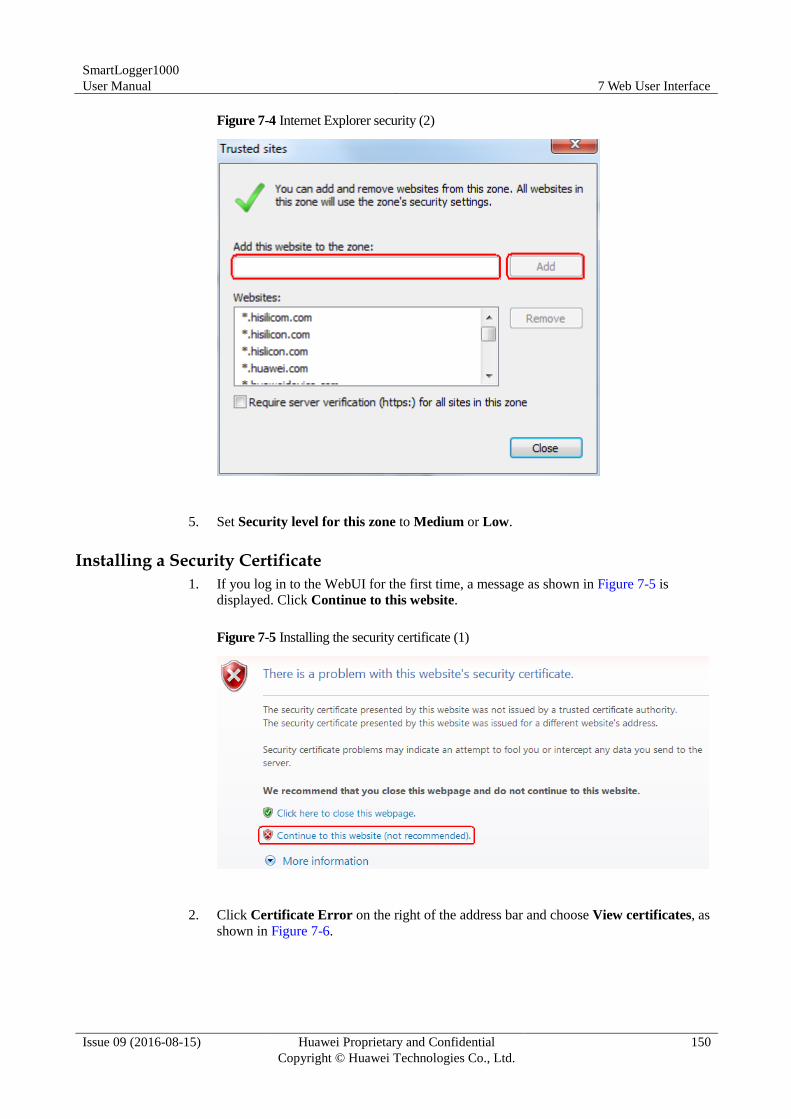
SmartLogger1000
User Manual 7 Web User Interface
Issue 09 (2016-08-15) Huawei Proprietary and Confidential
Copyright © Huawei Technologies Co., Ltd.
150
Figure 7-4 Internet Explorer security (2)
5. Set Security level for this zone to Medium or Low.
Installing a Security Certificate
1. If you log in to the WebUI for the first time, a message as shown in Figure 7-5 is
displayed. Click Continue to this website.
Figure 7-5 Installing the security certificate (1)
2. Click Certificate Error on the right of the address bar and choose View certificates, as
shown in Figure 7-6.
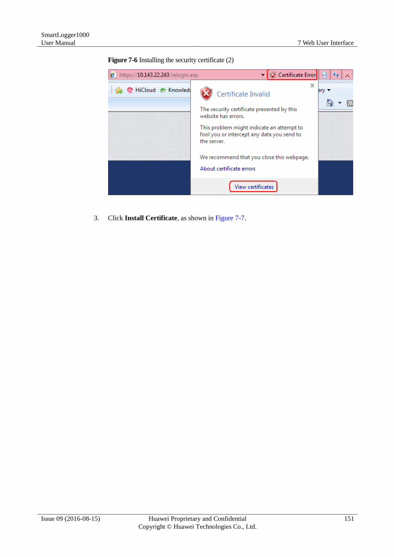
SmartLogger1000
User Manual 7 Web User Interface
Issue 09 (2016-08-15) Huawei Proprietary and Confidential
Copyright © Huawei Technologies Co., Ltd.
151
Figure 7-6 Installing the security certificate (2)
3. Click Install Certificate, as shown in Figure 7-7.
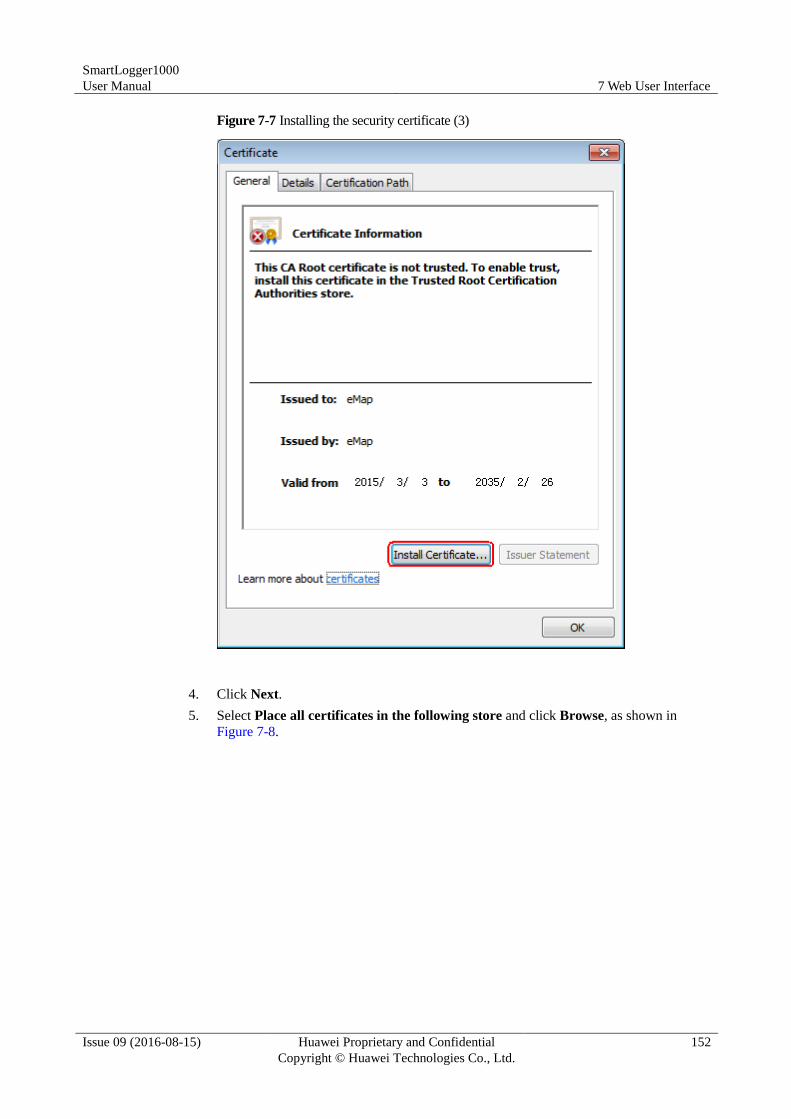
SmartLogger1000
User Manual 7 Web User Interface
Issue 09 (2016-08-15) Huawei Proprietary and Confidential
Copyright © Huawei Technologies Co., Ltd.
152
Figure 7-7 Installing the security certificate (3)
4. Click Next.
5. Select Place all certificates in the following store and click Browse, as shown in
Figure 7-8.
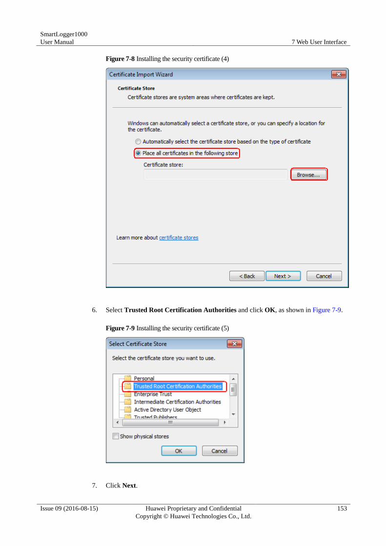
SmartLogger1000
User Manual 7 Web User Interface
Issue 09 (2016-08-15) Huawei Proprietary and Confidential
Copyright © Huawei Technologies Co., Ltd.
153
Figure 7-8 Installing the security certificate (4)
6. Select Trusted Root Certification Authorities and click OK, as shown in Figure 7-9.
Figure 7-9 Installing the security certificate (5)
7. Click Next.
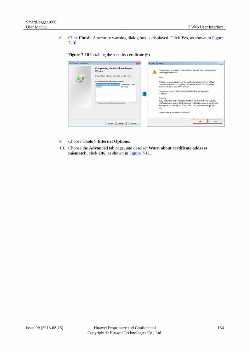
SmartLogger1000
User Manual 7 Web User Interface
Issue 09 (2016-08-15) Huawei Proprietary and Confidential
Copyright © Huawei Technologies Co., Ltd.
154
8. Click Finish. A security warning dialog box is displayed. Click Yes, as shown in Figure
7-10.
Figure 7-10 Installing the security certificate (6)
9. Choose Tools > Internet Options.
10. Choose the Advanced tab page, and deselect Warn about certificate address
mismatch, click OK, as shown in Figure 7-11.
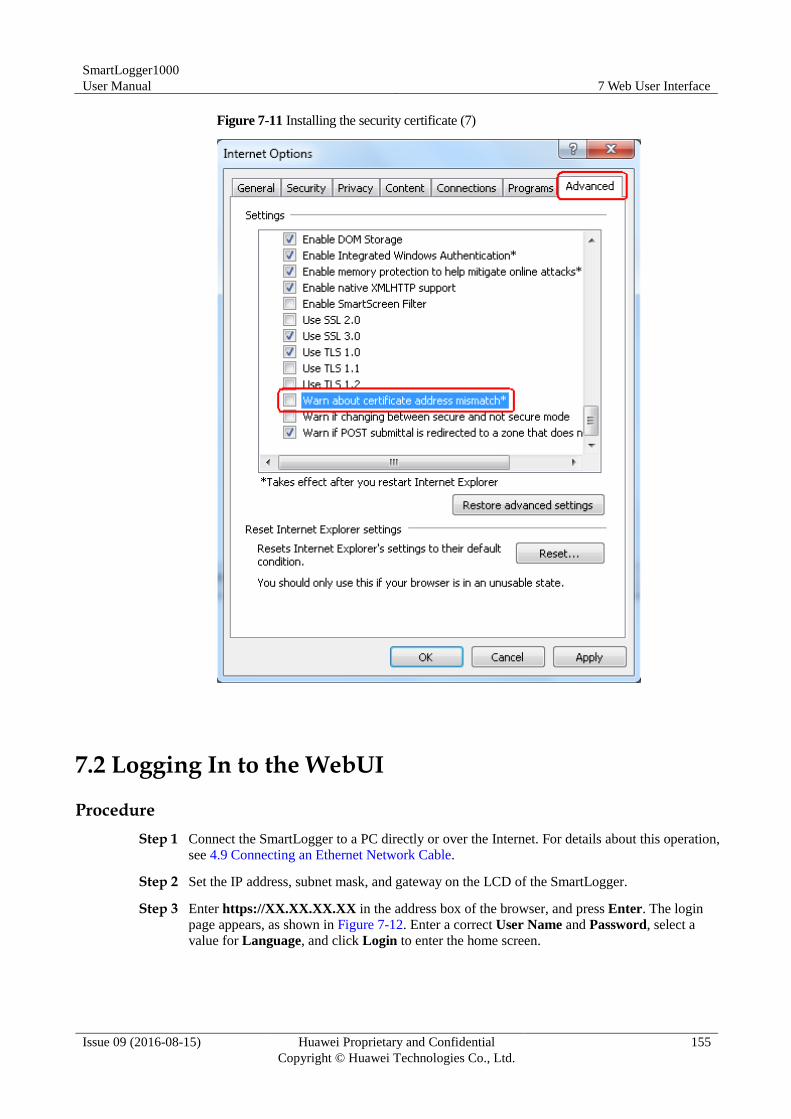
SmartLogger1000
User Manual 7 Web User Interface
Issue 09 (2016-08-15) Huawei Proprietary and Confidential
Copyright © Huawei Technologies Co., Ltd.
155
Figure 7-11 Installing the security certificate (7)
7.2 Logging In to the WebUI
Procedure
Step 1 Connect the SmartLogger to a PC directly or over the Internet. For details about this operation,
see 4.9 Connecting an Ethernet Network Cable.
Step 2 Set the IP address, subnet mask, and gateway on the LCD of the SmartLogger.
Step 3 Enter https://XX.XX.XX.XX in the address box of the browser, and press Enter. The login
page appears, as shown in Figure 7-12. Enter a correct User Name and Password, select a
value for Language, and click Login to enter the home screen.
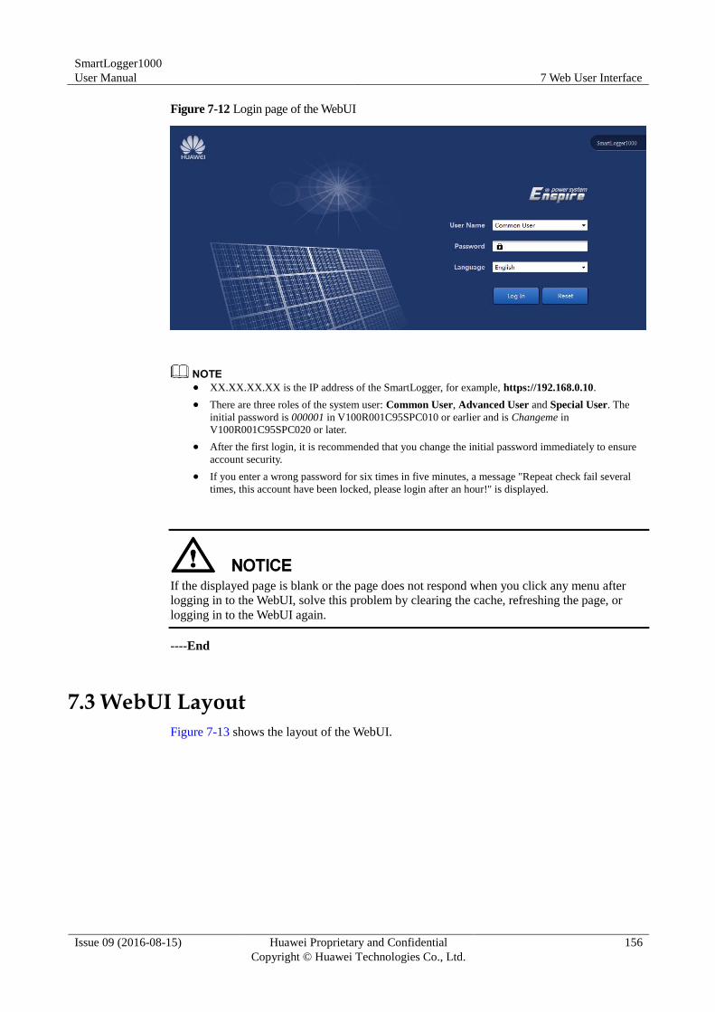
SmartLogger1000
User Manual 7 Web User Interface
Issue 09 (2016-08-15) Huawei Proprietary and Confidential
Copyright © Huawei Technologies Co., Ltd.
156
Figure 7-12 Login page of the WebUI
XX.XX.XX.XX is the IP address of the SmartLogger, for example, https://192.168.0.10.
There are three roles of the system user: Common User, Advanced User and Special User. The
initial password is 000001 in V100R001C95SPC010 or earlier and is Changeme in
V100R001C95SPC020 or later.
After the first login, it is recommended that you change the initial password immediately to ensure
account security.
If you enter a wrong password for six times in five minutes, a message "Repeat check fail several
times, this account have been locked, please login after an hour!" is displayed.
If the displayed page is blank or the page does not respond when you click any menu after
logging in to the WebUI, solve this problem by clearing the cache, refreshing the page, or
logging in to the WebUI again.
----End
7.3 WebUI Layout
Figure 7-13 shows the layout of the WebUI.
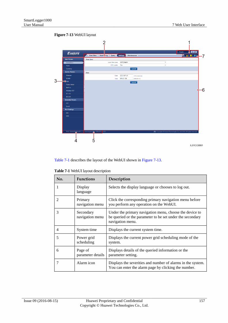
SmartLogger1000
User Manual 7 Web User Interface
Issue 09 (2016-08-15) Huawei Proprietary and Confidential
Copyright © Huawei Technologies Co., Ltd.
157
Figure 7-13 WebUI layout
Table 7-1 describes the layout of the WebUI shown in Figure 7-13.
Table 7-1 WebUI layout description
No. Functions Description
1 Display
language
Selects the display language or chooses to log out.
2 Primary
navigation menu
Click the corresponding primary navigation menu before
you perform any operation on the WebUI.
3 Secondary
navigation menu
Under the primary navigation menu, choose the device to
be queried or the parameter to be set under the secondary
navigation menu.
4 System time Displays the current system time.
5 Power grid
scheduling
Displays the current power grid scheduling mode of the
system.
6 Page of
parameter details
Displays details of the queried information or the
parameter setting.
7 Alarm icon Displays the severities and number of alarms in the system.
You can enter the alarm page by clicking the number.
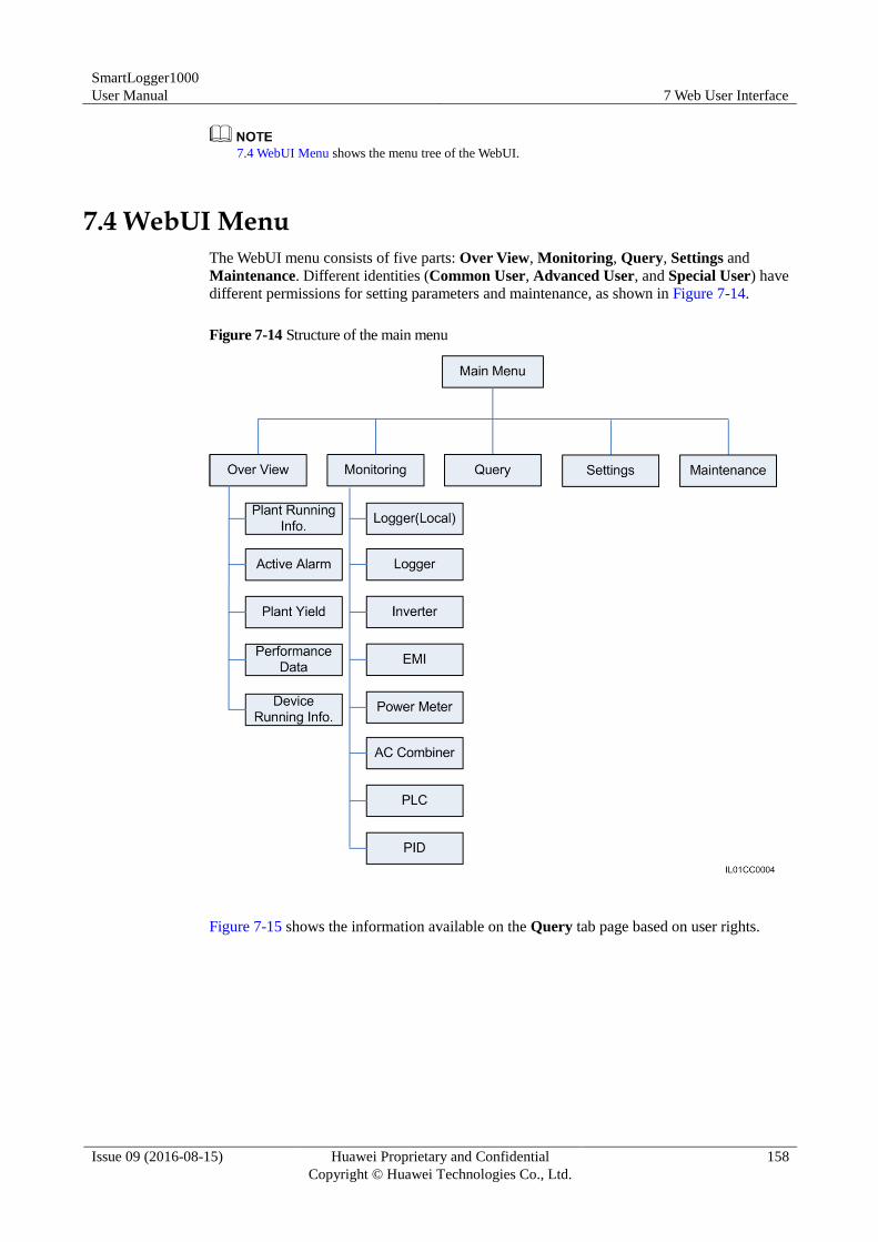
SmartLogger1000
User Manual 7 Web User Interface
Issue 09 (2016-08-15) Huawei Proprietary and Confidential
Copyright © Huawei Technologies Co., Ltd.
158
7.4 WebUI Menu shows the menu tree of the WebUI.
7.4 WebUI Menu
The WebUI menu consists of five parts: Over View, Monitoring, Query, Settings and
Maintenance. Different identities (Common User, Advanced User, and Special User) have
different permissions for setting parameters and maintenance, as shown in Figure 7-14.
Figure 7-14 Structure of the main menu
Figure 7-15 shows the information available on the Query tab page based on user rights.
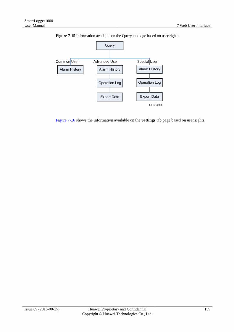
SmartLogger1000
User Manual 7 Web User Interface
Issue 09 (2016-08-15) Huawei Proprietary and Confidential
Copyright © Huawei Technologies Co., Ltd.
159
Figure 7-15 Information available on the Query tab page based on user rights
Figure 7-16 shows the information available on the Settings tab page based on user rights.
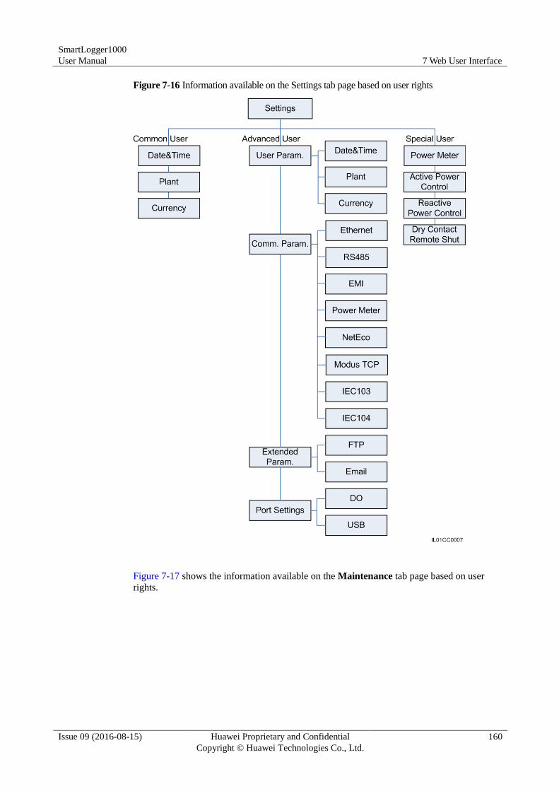
SmartLogger1000
User Manual 7 Web User Interface
Issue 09 (2016-08-15) Huawei Proprietary and Confidential
Copyright © Huawei Technologies Co., Ltd.
160
Figure 7-16 Information available on the Settings tab page based on user rights
Figure 7-17 shows the information available on the Maintenance tab page based on user
rights.
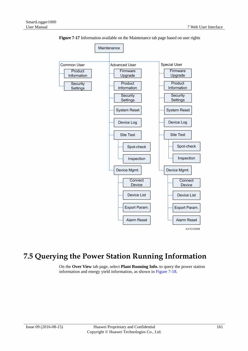
SmartLogger1000
User Manual 7 Web User Interface
Issue 09 (2016-08-15) Huawei Proprietary and Confidential
Copyright © Huawei Technologies Co., Ltd.
161
Figure 7-17 Information available on the Maintenance tab page based on user rights
7.5 Querying the Power Station Running Information
On the Over View tab page, select Plant Running Info. to query the power station
information and energy yield information, as shown in Figure 7-18.
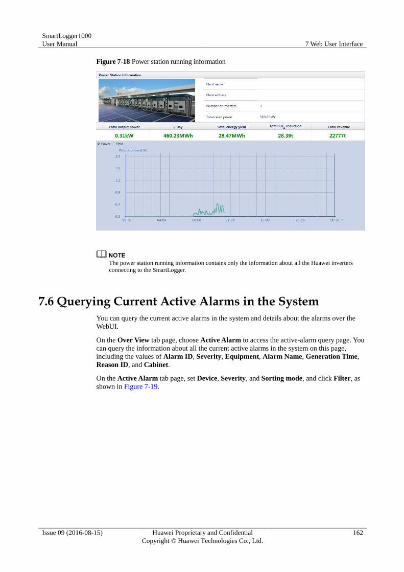
SmartLogger1000
User Manual 7 Web User Interface
Issue 09 (2016-08-15) Huawei Proprietary and Confidential
Copyright © Huawei Technologies Co., Ltd.
162
Figure 7-18 Power station running information
The power station running information contains only the information about all the Huawei inverters
connecting to the SmartLogger.
7.6 Querying Current Active Alarms in the System
You can query the current active alarms in the system and details about the alarms over the
WebUI.
On the Over View tab page, choose Active Alarm to access the active-alarm query page. You
can query the information about all the current active alarms in the system on this page,
including the values of Alarm ID, Severity, Equipment, Alarm Name, Generation Time,
Reason ID, and Cabinet.
On the Active Alarm tab page, set Device, Severity, and Sorting mode, and click Filter, as
shown in Figure 7-19.
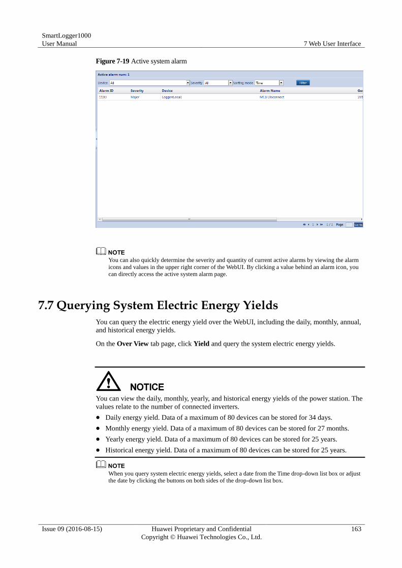
SmartLogger1000
User Manual 7 Web User Interface
Issue 09 (2016-08-15) Huawei Proprietary and Confidential
Copyright © Huawei Technologies Co., Ltd.
163
Figure 7-19 Active system alarm
You can also quickly determine the severity and quantity of current active alarms by viewing the alarm
icons and values in the upper right corner of the WebUI. By clicking a value behind an alarm icon, you
can directly access the active system alarm page.
7.7 Querying System Electric Energy Yields
You can query the electric energy yield over the WebUI, including the daily, monthly, annual,
and historical energy yields.
On the Over View tab page, click Yield and query the system electric energy yields.
You can view the daily, monthly, yearly, and historical energy yields of the power station. The
values relate to the number of connected inverters.
Daily energy yield. Data of a maximum of 80 devices can be stored for 34 days.
Monthly energy yield. Data of a maximum of 80 devices can be stored for 27 months.
Yearly energy yield. Data of a maximum of 80 devices can be stored for 25 years.
Historical energy yield. Data of a maximum of 80 devices can be stored for 25 years.
When you query system electric energy yields, select a date from the Time drop-down list box or adjust
the date by clicking the buttons on both sides of the drop-down list box.
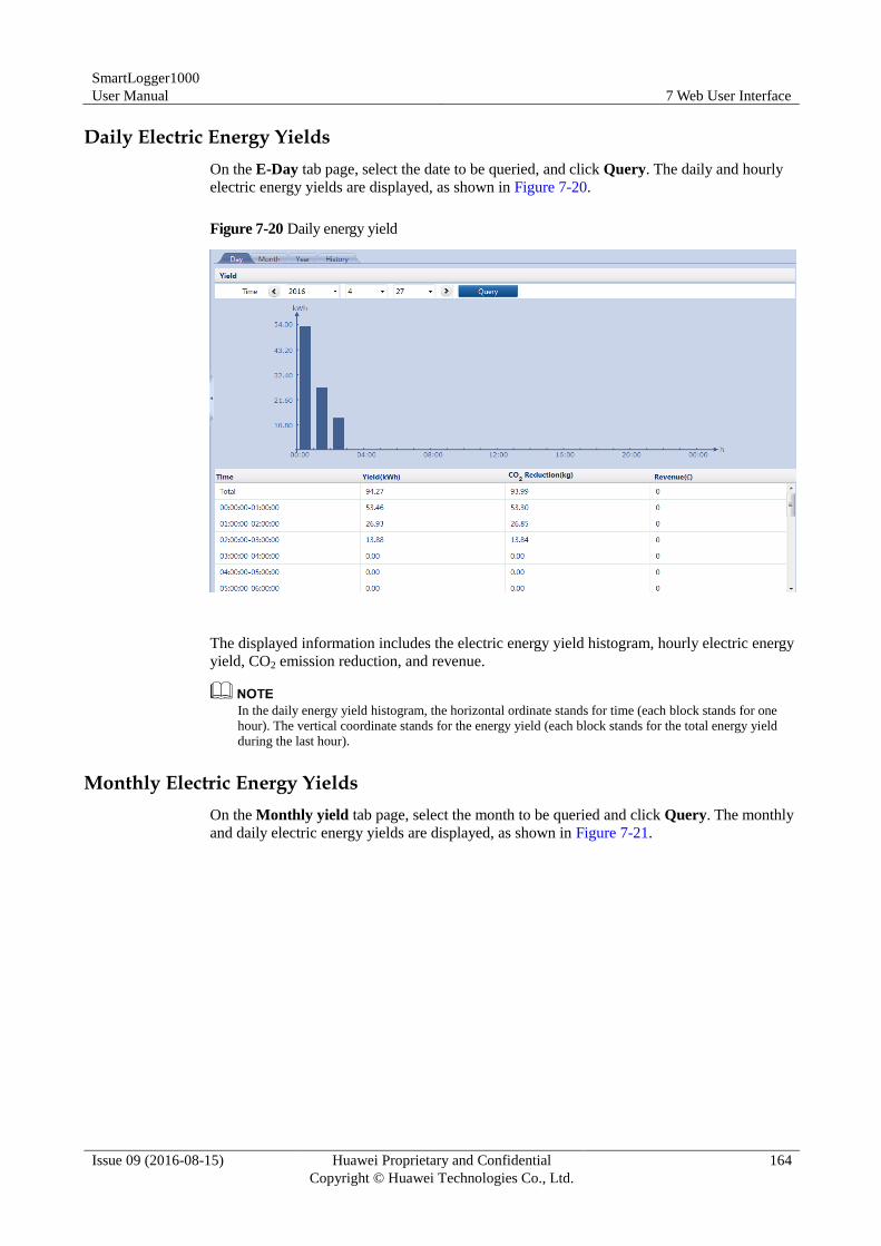
SmartLogger1000
User Manual 7 Web User Interface
Issue 09 (2016-08-15) Huawei Proprietary and Confidential
Copyright © Huawei Technologies Co., Ltd.
164
Daily Electric Energy Yields
On the E-Day tab page, select the date to be queried, and click Query. The daily and hourly
electric energy yields are displayed, as shown in Figure 7-20.
Figure 7-20 Daily energy yield
The displayed information includes the electric energy yield histogram, hourly electric energy
yield, CO2 emission reduction, and revenue.
In the daily energy yield histogram, the horizontal ordinate stands for time (each block stands for one
hour). The vertical coordinate stands for the energy yield (each block stands for the total energy yield
during the last hour).
Monthly Electric Energy Yields
On the Monthly yield tab page, select the month to be queried and click Query. The monthly
and daily electric energy yields are displayed, as shown in Figure 7-21.
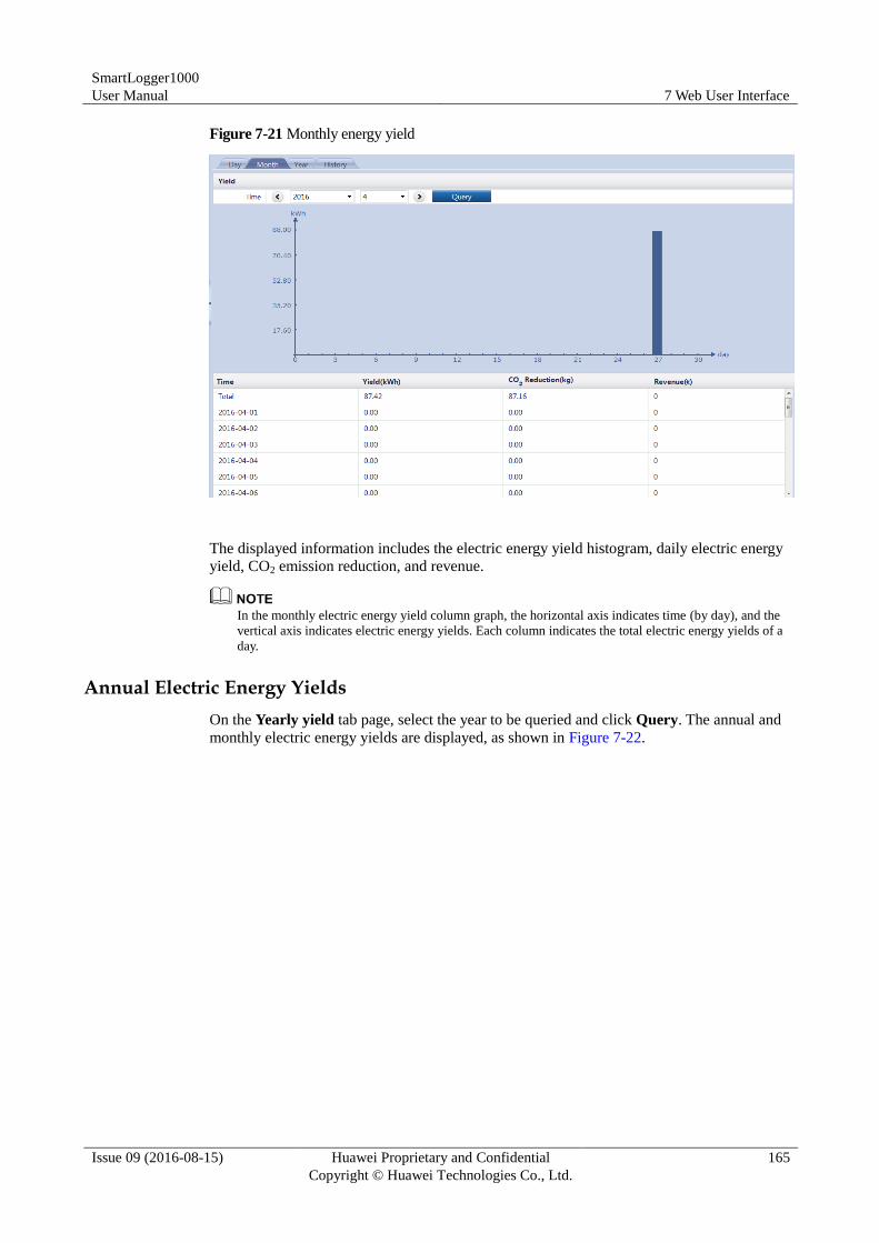
SmartLogger1000
User Manual 7 Web User Interface
Issue 09 (2016-08-15) Huawei Proprietary and Confidential
Copyright © Huawei Technologies Co., Ltd.
165
Figure 7-21 Monthly energy yield
The displayed information includes the electric energy yield histogram, daily electric energy
yield, CO2 emission reduction, and revenue.
In the monthly electric energy yield column graph, the horizontal axis indicates time (by day), and the
vertical axis indicates electric energy yields. Each column indicates the total electric energy yields of a
day.
Annual Electric Energy Yields
On the Yearly yield tab page, select the year to be queried and click Query. The annual and
monthly electric energy yields are displayed, as shown in Figure 7-22.
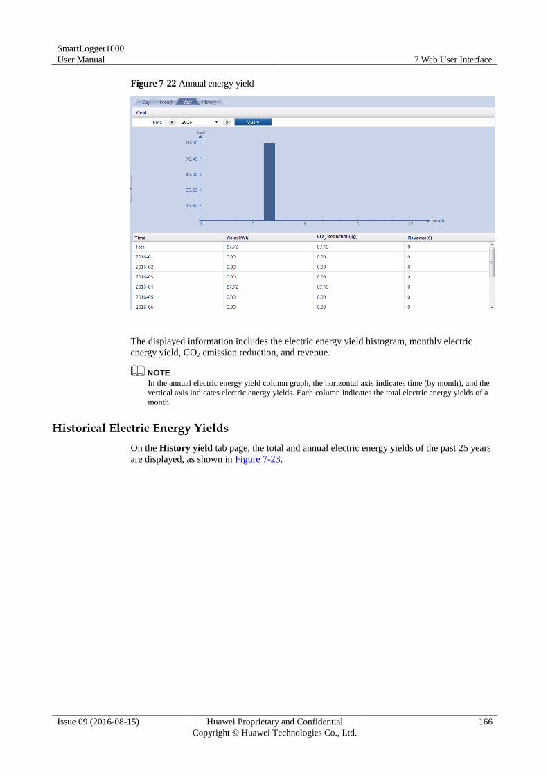
SmartLogger1000
User Manual 7 Web User Interface
Issue 09 (2016-08-15) Huawei Proprietary and Confidential
Copyright © Huawei Technologies Co., Ltd.
166
Figure 7-22 Annual energy yield
The displayed information includes the electric energy yield histogram, monthly electric
energy yield, CO2 emission reduction, and revenue.
In the annual electric energy yield column graph, the horizontal axis indicates time (by month), and the
vertical axis indicates electric energy yields. Each column indicates the total electric energy yields of a
month.
Historical Electric Energy Yields
On the History yield tab page, the total and annual electric energy yields of the past 25 years
are displayed, as shown in Figure 7-23.
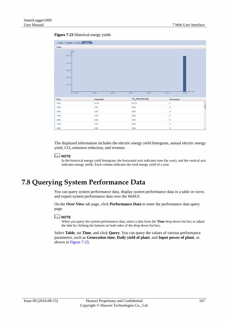
SmartLogger1000
User Manual 7 Web User Interface
Issue 09 (2016-08-15) Huawei Proprietary and Confidential
Copyright © Huawei Technologies Co., Ltd.
167
Figure 7-23 Historical energy yields
The displayed information includes the electric energy yield histogram, annual electric energy
yield, CO2 emission reduction, and revenue.
In the historical energy yield histogram, the horizontal axis indicates time (by year), and the vertical axis
indicates energy yields. Each column indicates the total energy yield of a year.
7.8 Querying System Performance Data
You can query system performance data, display system performance data in a table or curve,
and export system performance data over the WebUI.
On the Over View tab page, click Performance Data to enter the performance data query
page.
When you query the system performance data, select a date from the Time drop-down list box or adjust
the date by clicking the buttons on both sides of the drop-down list box.
Select Table, set Time, and click Query. You can query the values of various performance
parameters, such as Generation time, Daily yield of plant, and Input power of plant, as
shown in Figure 7-25.
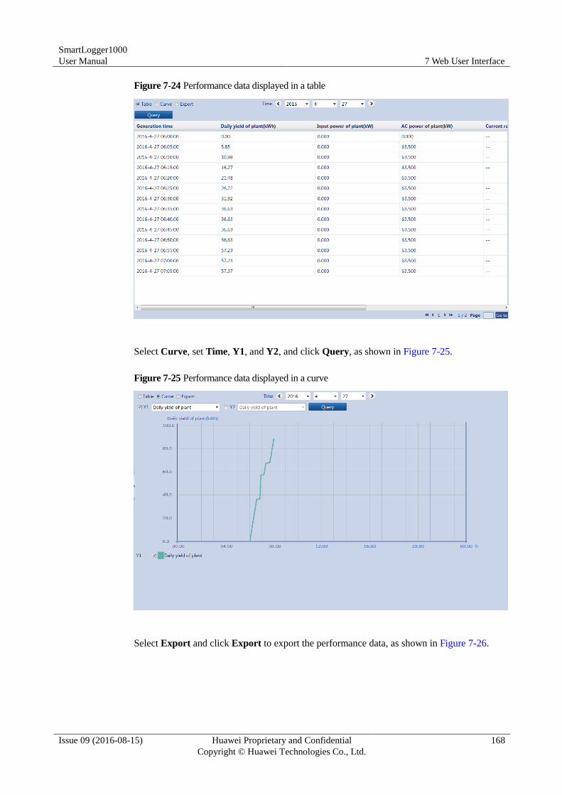
SmartLogger1000
User Manual 7 Web User Interface
Issue 09 (2016-08-15) Huawei Proprietary and Confidential
Copyright © Huawei Technologies Co., Ltd.
168
Figure 7-24 Performance data displayed in a table
Select Curve, set Time, Y1, and Y2, and click Query, as shown in Figure 7-25.
Figure 7-25 Performance data displayed in a curve
Select Export and click Export to export the performance data, as shown in Figure 7-26.
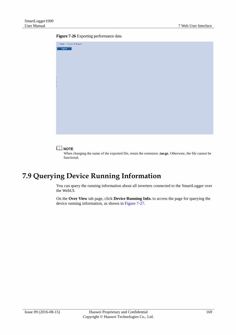
SmartLogger1000
User Manual 7 Web User Interface
Issue 09 (2016-08-15) Huawei Proprietary and Confidential
Copyright © Huawei Technologies Co., Ltd.
169
Figure 7-26 Exporting performance data
When changing the name of the exported file, retain the extension .tar.gz. Otherwise, the file cannot be
functional.
7.9 Querying Device Running Information
You can query the running information about all inverters connected to the SmartLogger over
the WebUI.
On the Over View tab page, click Device Running Info. to access the page for querying the
device running information, as shown in Figure 7-27.
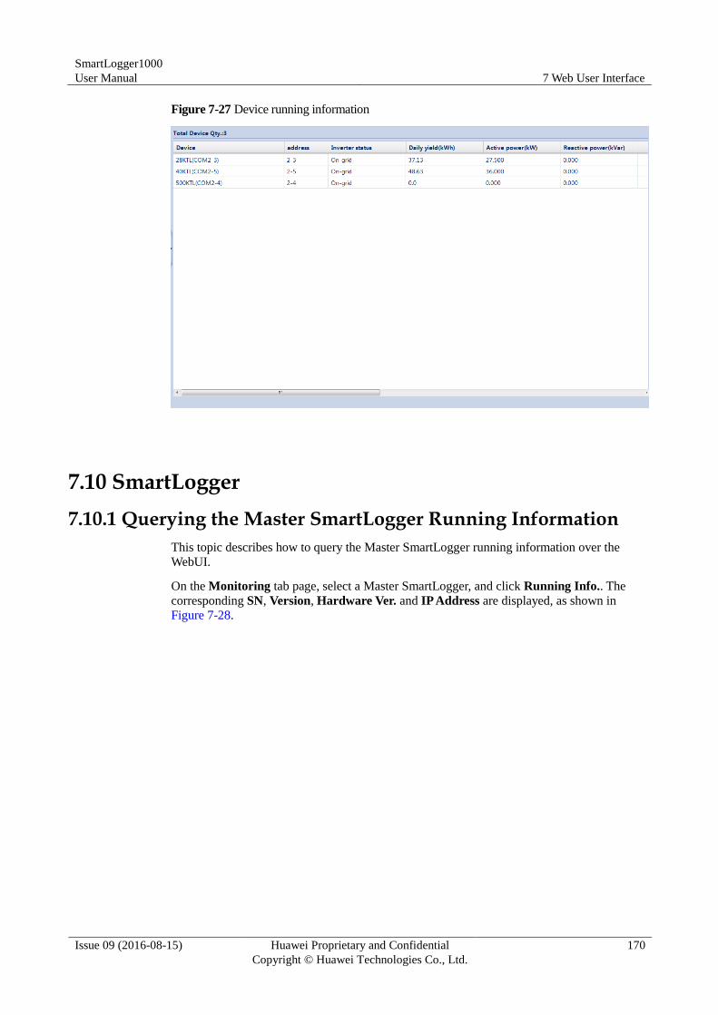
SmartLogger1000
User Manual 7 Web User Interface
Issue 09 (2016-08-15) Huawei Proprietary and Confidential
Copyright © Huawei Technologies Co., Ltd.
170
Figure 7-27 Device running information
7.10 SmartLogger
7.10.1 Querying the Master SmartLogger Running Information
This topic describes how to query the Master SmartLogger running information over the
WebUI.
On the Monitoring tab page, select a Master SmartLogger, and click Running Info.. The
corresponding SN, Version, Hardware Ver. and IP Address are displayed, as shown in
Figure 7-28.
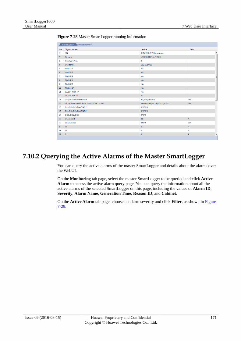
SmartLogger1000
User Manual 7 Web User Interface
Issue 09 (2016-08-15) Huawei Proprietary and Confidential
Copyright © Huawei Technologies Co., Ltd.
171
Figure 7-28 Master SmartLogger running information
7.10.2 Querying the Active Alarms of the Master SmartLogger
You can query the active alarms of the master SmartLogger and details about the alarms over
the WebUI.
On the Monitoring tab page, select the master SmartLogger to be queried and click Active
Alarm to access the active alarm query page. You can query the information about all the
active alarms of the selected SmartLogger on this page, including the values of Alarm ID,
Severity, Alarm Name, Generation Time, Reason ID, and Cabinet.
On the Active Alarm tab page, choose an alarm severity and click Filter, as shown in Figure
7-29.
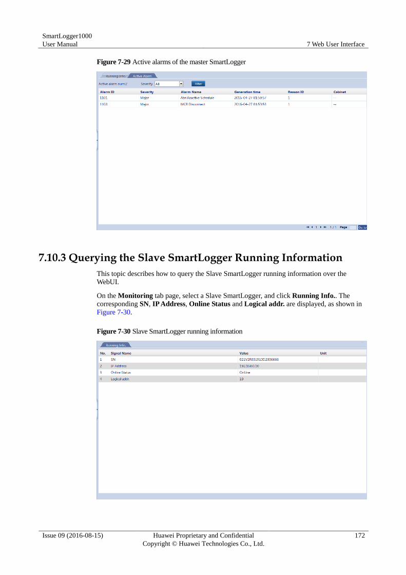
SmartLogger1000
User Manual 7 Web User Interface
Issue 09 (2016-08-15) Huawei Proprietary and Confidential
Copyright © Huawei Technologies Co., Ltd.
172
Figure 7-29 Active alarms of the master SmartLogger
7.10.3 Querying the Slave SmartLogger Running Information
This topic describes how to query the Slave SmartLogger running information over the
WebUI.
On the Monitoring tab page, select a Slave SmartLogger, and click Running Info.. The
corresponding SN, IP Address, Online Status and Logical addr. are displayed, as shown in
Figure 7-30.
Figure 7-30 Slave SmartLogger running information
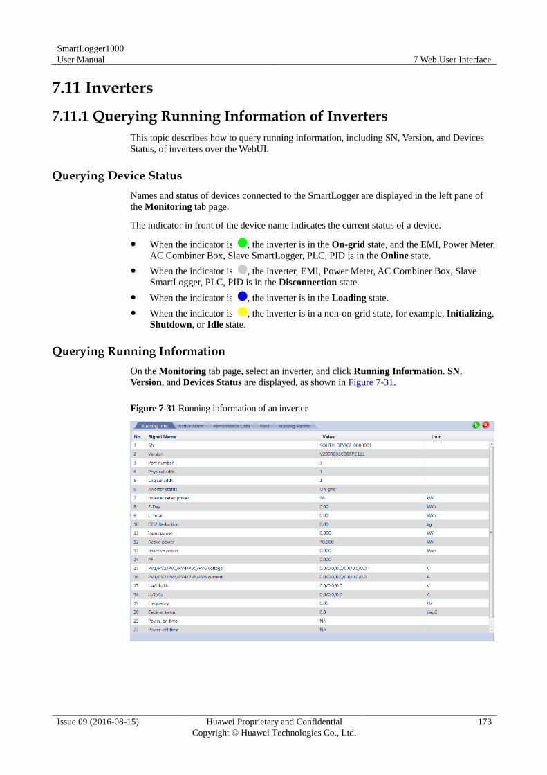
SmartLogger1000
User Manual 7 Web User Interface
Issue 09 (2016-08-15) Huawei Proprietary and Confidential
Copyright © Huawei Technologies Co., Ltd.
173
7.11 Inverters
7.11.1 Querying Running Information of Inverters
This topic describes how to query running information, including SN, Version, and Devices
Status, of inverters over the WebUI.
Querying Device Status
Names and status of devices connected to the SmartLogger are displayed in the left pane of
the Monitoring tab page.
The indicator in front of the device name indicates the current status of a device.
When the indicator is , the inverter is in the On-grid state, and the EMI, Power Meter,
AC Combiner Box, Slave SmartLogger, PLC, PID is in the Online state.
When the indicator is , the inverter, EMI, Power Meter, AC Combiner Box, Slave
SmartLogger, PLC, PID is in the Disconnection state.
When the indicator is , the inverter is in the Loading state.
When the indicator is , the inverter is in a non-on-grid state, for example, Initializing,
Shutdown, or Idle state.
Querying Running Information
On the Monitoring tab page, select an inverter, and click Running Information. SN,
Version, and Devices Status are displayed, as shown in Figure 7-31.
Figure 7-31 Running information of an inverter
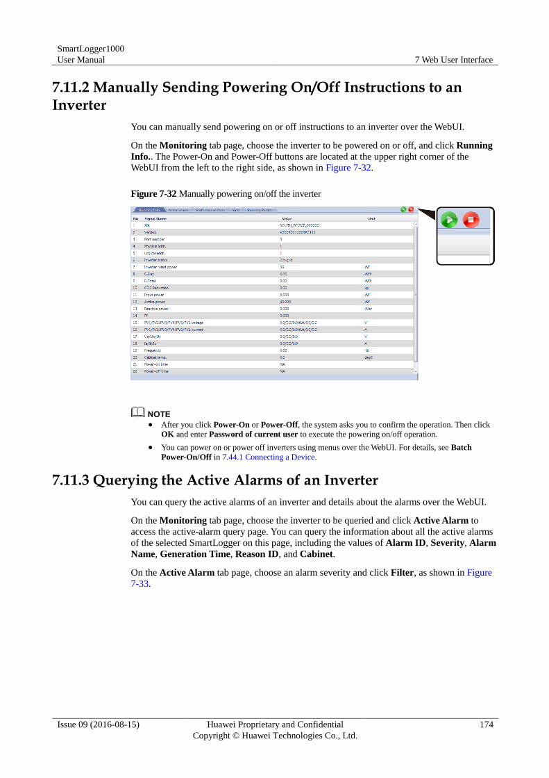
SmartLogger1000
User Manual 7 Web User Interface
Issue 09 (2016-08-15) Huawei Proprietary and Confidential
Copyright © Huawei Technologies Co., Ltd.
174
7.11.2 Manually Sending Powering On/Off Instructions to an Inverter
You can manually send powering on or off instructions to an inverter over the WebUI.
On the Monitoring tab page, choose the inverter to be powered on or off, and click Running
Info.. The Power-On and Power-Off buttons are located at the upper right corner of the
WebUI from the left to the right side, as shown in Figure 7-32.
Figure 7-32 Manually powering on/off the inverter
After you click Power-On or Power-Off, the system asks you to confirm the operation. Then click
OK and enter Password of current user to execute the powering on/off operation.
You can power on or power off inverters using menus over the WebUI. For details, see Batch
Power-On/Off in 7.44.1 Connecting a Device.
7.11.3 Querying the Active Alarms of an Inverter
You can query the active alarms of an inverter and details about the alarms over the WebUI.
On the Monitoring tab page, choose the inverter to be queried and click Active Alarm to
access the active-alarm query page. You can query the information about all the active alarms
of the selected SmartLogger on this page, including the values of Alarm ID, Severity, Alarm
Name, Generation Time, Reason ID, and Cabinet.
On the Active Alarm tab page, choose an alarm severity and click Filter, as shown in Figure
7-33.
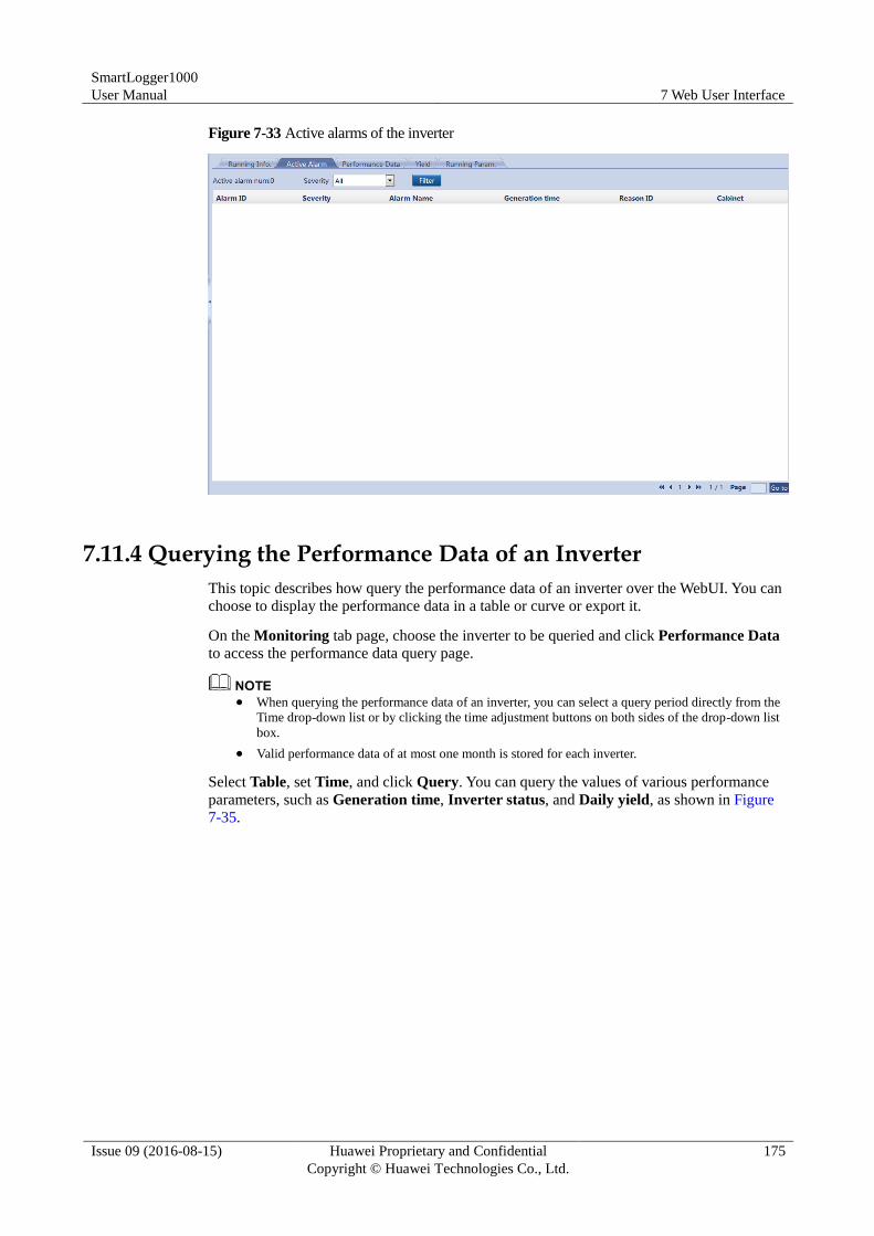
SmartLogger1000
User Manual 7 Web User Interface
Issue 09 (2016-08-15) Huawei Proprietary and Confidential
Copyright © Huawei Technologies Co., Ltd.
175
Figure 7-33 Active alarms of the inverter
7.11.4 Querying the Performance Data of an Inverter
This topic describes how query the performance data of an inverter over the WebUI. You can
choose to display the performance data in a table or curve or export it.
On the Monitoring tab page, choose the inverter to be queried and click Performance Data
to access the performance data query page.
When querying the performance data of an inverter, you can select a query period directly from the
Time drop-down list or by clicking the time adjustment buttons on both sides of the drop-down list
box.
Valid performance data of at most one month is stored for each inverter.
Select Table, set Time, and click Query. You can query the values of various performance
parameters, such as Generation time, Inverter status, and Daily yield, as shown in Figure
7-35.
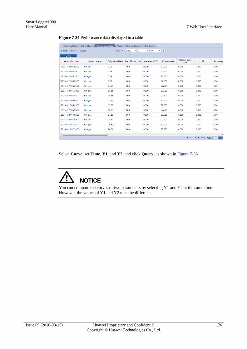
SmartLogger1000
User Manual 7 Web User Interface
Issue 09 (2016-08-15) Huawei Proprietary and Confidential
Copyright © Huawei Technologies Co., Ltd.
176
Figure 7-34 Performance data displayed in a table
Select Curve, set Time, Y1, and Y2, and click Query, as shown in Figure 7-35.
You can compare the curves of two parameters by selecting Y1 and Y2 at the same time.
However, the values of Y1 and Y2 must be different.
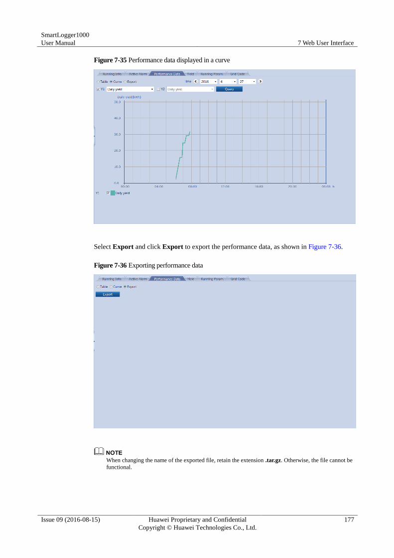
SmartLogger1000
User Manual 7 Web User Interface
Issue 09 (2016-08-15) Huawei Proprietary and Confidential
Copyright © Huawei Technologies Co., Ltd.
177
Figure 7-35 Performance data displayed in a curve
Select Export and click Export to export the performance data, as shown in Figure 7-36.
Figure 7-36 Exporting performance data
When changing the name of the exported file, retain the extension .tar.gz. Otherwise, the file cannot be
functional.
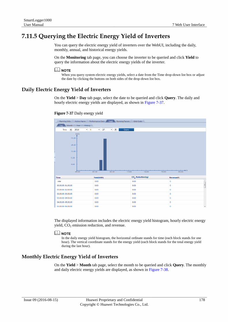
SmartLogger1000
User Manual 7 Web User Interface
Issue 09 (2016-08-15) Huawei Proprietary and Confidential
Copyright © Huawei Technologies Co., Ltd.
178
7.11.5 Querying the Electric Energy Yield of Inverters
You can query the electric energy yield of inverters over the WebUI, including the daily,
monthly, annual, and historical energy yields.
On the Monitoring tab page, you can choose the inverter to be queried and click Yield to
query the information about the electric energy yields of the inverter.
When you query system electric energy yields, select a date from the Time drop-down list box or adjust
the date by clicking the buttons on both sides of the drop-down list box.
Daily Electric Energy Yield of Inverters
On the Yield > Day tab page, select the date to be queried and click Query. The daily and
hourly electric energy yields are displayed, as shown in Figure 7-37.
Figure 7-37 Daily energy yield
The displayed information includes the electric energy yield histogram, hourly electric energy
yield, CO2 emission reduction, and revenue.
In the daily energy yield histogram, the horizontal ordinate stands for time (each block stands for one
hour). The vertical coordinate stands for the energy yield (each block stands for the total energy yield
during the last hour).
Monthly Electric Energy Yield of Inverters
On the Yield > Month tab page, select the month to be queried and click Query. The monthly
and daily electric energy yields are displayed, as shown in Figure 7-38.
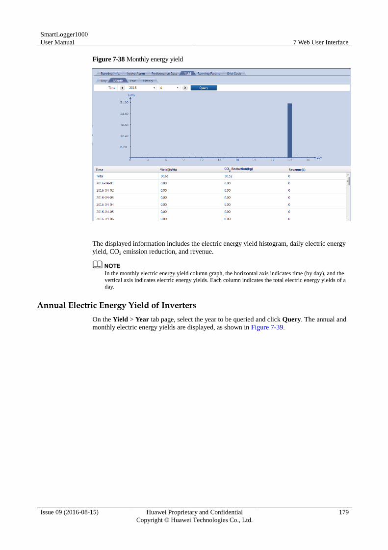
SmartLogger1000
User Manual 7 Web User Interface
Issue 09 (2016-08-15) Huawei Proprietary and Confidential
Copyright © Huawei Technologies Co., Ltd.
179
Figure 7-38 Monthly energy yield
The displayed information includes the electric energy yield histogram, daily electric energy
yield, CO2 emission reduction, and revenue.
In the monthly electric energy yield column graph, the horizontal axis indicates time (by day), and the
vertical axis indicates electric energy yields. Each column indicates the total electric energy yields of a
day.
Annual Electric Energy Yield of Inverters
On the Yield > Year tab page, select the year to be queried and click Query. The annual and
monthly electric energy yields are displayed, as shown in Figure 7-39.
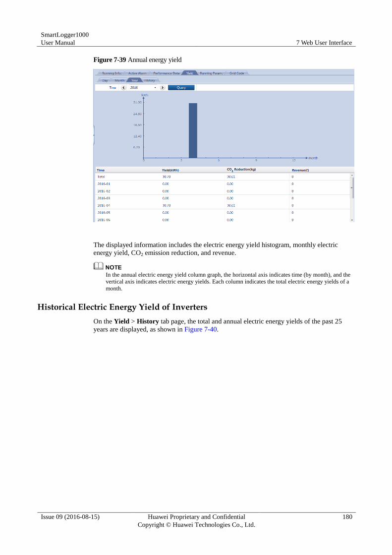
SmartLogger1000
User Manual 7 Web User Interface
Issue 09 (2016-08-15) Huawei Proprietary and Confidential
Copyright © Huawei Technologies Co., Ltd.
180
Figure 7-39 Annual energy yield
The displayed information includes the electric energy yield histogram, monthly electric
energy yield, CO2 emission reduction, and revenue.
In the annual electric energy yield column graph, the horizontal axis indicates time (by month), and the
vertical axis indicates electric energy yields. Each column indicates the total electric energy yields of a
month.
Historical Electric Energy Yield of Inverters
On the Yield > History tab page, the total and annual electric energy yields of the past 25
years are displayed, as shown in Figure 7-40.
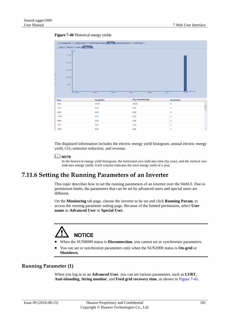
SmartLogger1000
User Manual 7 Web User Interface
Issue 09 (2016-08-15) Huawei Proprietary and Confidential
Copyright © Huawei Technologies Co., Ltd.
181
Figure 7-40 Historical energy yields
The displayed information includes the electric energy yield histogram, annual electric energy
yield, CO2 emission reduction, and revenue.
In the historical energy yield histogram, the horizontal axis indicates time (by year), and the vertical axis
indicates energy yields. Each column indicates the total energy yield of a year.
7.11.6 Setting the Running Parameters of an Inverter
This topic describes how to set the running parameters of an inverter over the WebUI. Due to
permission limits, the parameters that can be set by advanced users and special users are
different.
On the Monitoring tab page, choose the inverter to be set and click Running Param. to
access the running parameter setting page. Because of the limited permission, select User
name as Advanced User or Special User.
When the SUN8000 status is Disconnection, you cannot set or synchronize parameters.
You can set or synchronize parameters only when the SUN2000 status is On-grid or
Shutdown.
Running Parameter (1)
When you log in as an Advanced User, you can set various parameters, such as LVRT,
Anti-islanding, String monitor, and Feed grid recovery time, as shown in Figure 7-41.
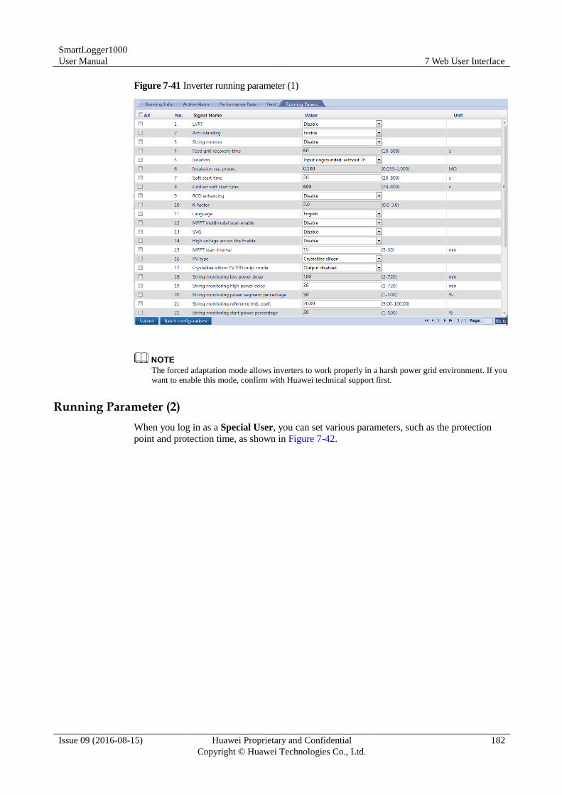
SmartLogger1000
User Manual 7 Web User Interface
Issue 09 (2016-08-15) Huawei Proprietary and Confidential
Copyright © Huawei Technologies Co., Ltd.
182
Figure 7-41 Inverter running parameter (1)
The forced adaptation mode allows inverters to work properly in a harsh power grid environment. If you
want to enable this mode, confirm with Huawei technical support first.
Running Parameter (2)
When you log in as a Special User, you can set various parameters, such as the protection
point and protection time, as shown in Figure 7-42.
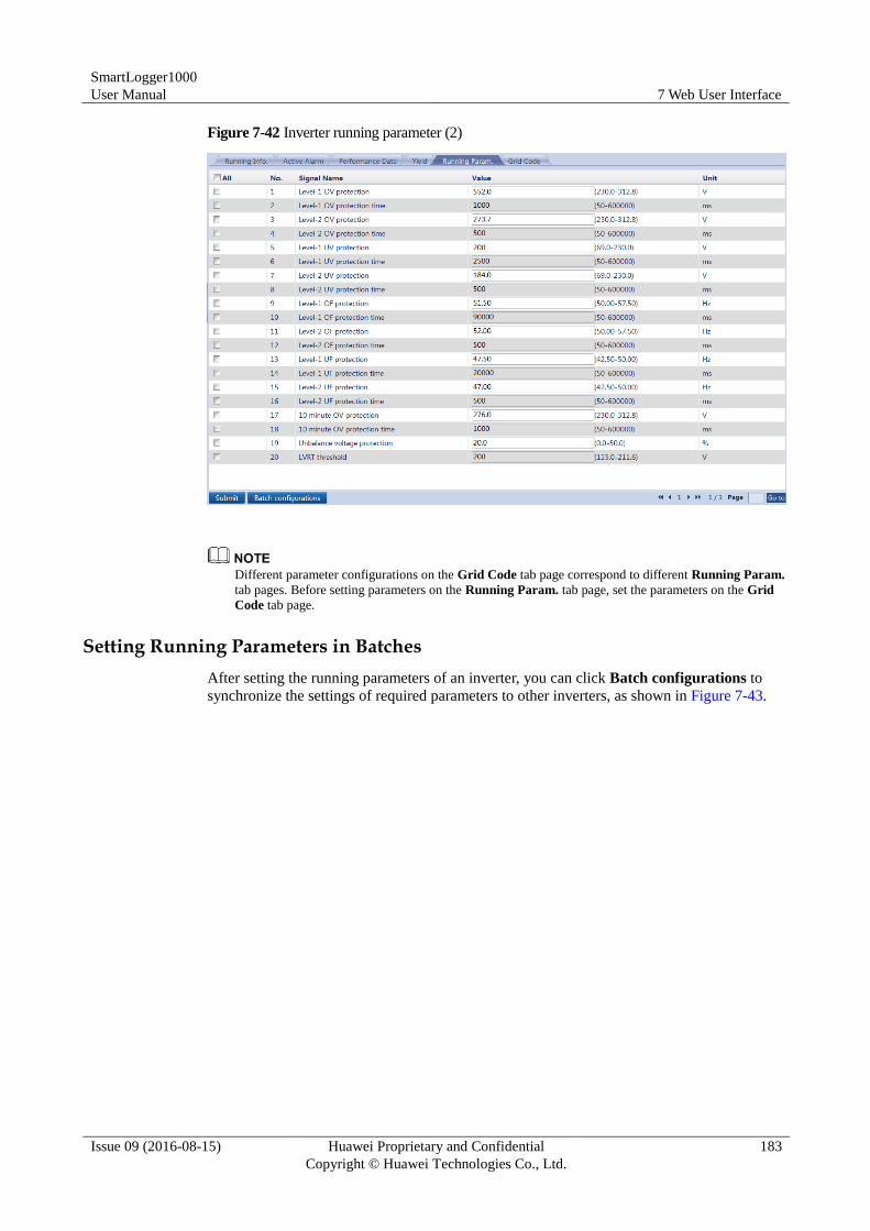
SmartLogger1000
User Manual 7 Web User Interface
Issue 09 (2016-08-15) Huawei Proprietary and Confidential
Copyright © Huawei Technologies Co., Ltd.
183
Figure 7-42 Inverter running parameter (2)
Different parameter configurations on the Grid Code tab page correspond to different Running Param.
tab pages. Before setting parameters on the Running Param. tab page, set the parameters on the Grid
Code tab page.
Setting Running Parameters in Batches
After setting the running parameters of an inverter, you can click Batch configurations to
synchronize the settings of required parameters to other inverters, as shown in Figure 7-43.
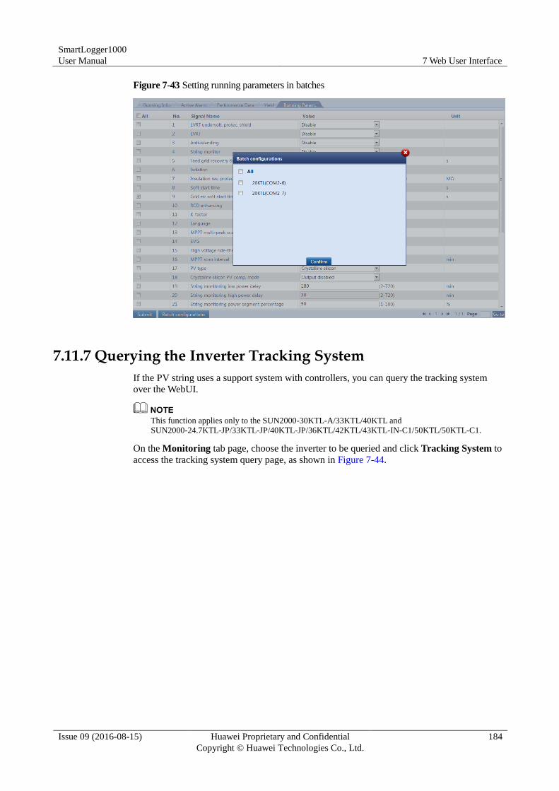
SmartLogger1000
User Manual 7 Web User Interface
Issue 09 (2016-08-15) Huawei Proprietary and Confidential
Copyright © Huawei Technologies Co., Ltd.
184
Figure 7-43 Setting running parameters in batches
7.11.7 Querying the Inverter Tracking System
If the PV string uses a support system with controllers, you can query the tracking system
over the WebUI.
This function applies only to the SUN2000-30KTL-A/33KTL/40KTL and
SUN2000-24.7KTL-JP/33KTL-JP/40KTL-JP/36KTL/42KTL/43KTL-IN-C1/50KTL/50KTL-C1.
On the Monitoring tab page, choose the inverter to be queried and click Tracking System to
access the tracking system query page, as shown in Figure 7-44.
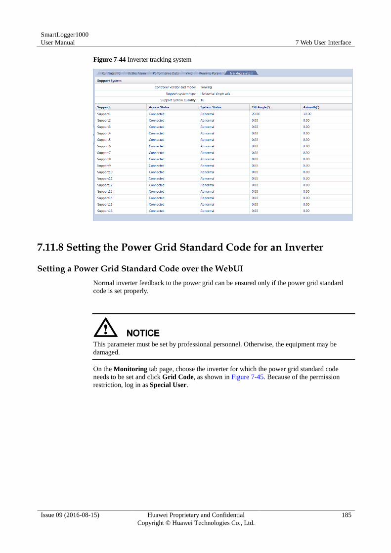
SmartLogger1000
User Manual 7 Web User Interface
Issue 09 (2016-08-15) Huawei Proprietary and Confidential
Copyright © Huawei Technologies Co., Ltd.
185
Figure 7-44 Inverter tracking system
7.11.8 Setting the Power Grid Standard Code for an Inverter
Setting a Power Grid Standard Code over the WebUI
Normal inverter feedback to the power grid can be ensured only if the power grid standard
code is set properly.
This parameter must be set by professional personnel. Otherwise, the equipment may be
damaged.
On the Monitoring tab page, choose the inverter for which the power grid standard code
needs to be set and click Grid Code, as shown in Figure 7-45. Because of the permission
restriction, log in as Special User.
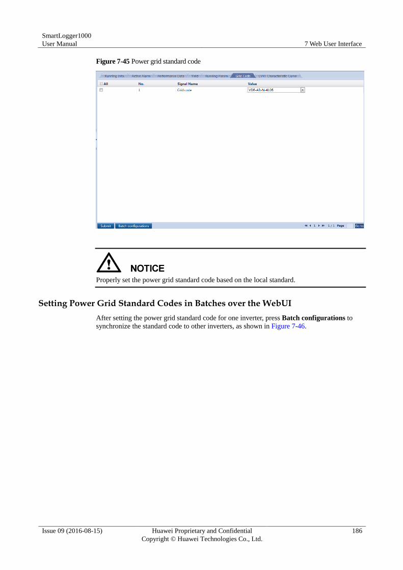
SmartLogger1000
User Manual 7 Web User Interface
Issue 09 (2016-08-15) Huawei Proprietary and Confidential
Copyright © Huawei Technologies Co., Ltd.
186
Figure 7-45 Power grid standard code
Properly set the power grid standard code based on the local standard.
Setting Power Grid Standard Codes in Batches over the WebUI
After setting the power grid standard code for one inverter, press Batch configurations to
synchronize the standard code to other inverters, as shown in Figure 7-46.
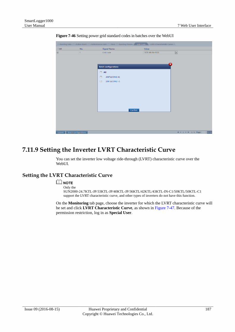
SmartLogger1000
User Manual 7 Web User Interface
Issue 09 (2016-08-15) Huawei Proprietary and Confidential
Copyright © Huawei Technologies Co., Ltd.
187
Figure 7-46 Setting power grid standard codes in batches over the WebUI
7.11.9 Setting the Inverter LVRT Characteristic Curve
You can set the inverter low voltage ride-through (LVRT) characteristic curve over the
WebUI.
Setting the LVRT Characteristic Curve
Only the
SUN2000-24.7KTL-JP/33KTL-JP/40KTL-JP/36KTL/42KTL/43KTL-IN-C1/50KTL/50KTL-C1
support the LVRT characteristic curve, and other types of inverters do not have this function.
On the Monitoring tab page, choose the inverter for which the LVRT characteristic curve will
be set and click LVRT Characteristic Curve, as shown in Figure 7-47. Because of the
permission restriction, log in as Special User.
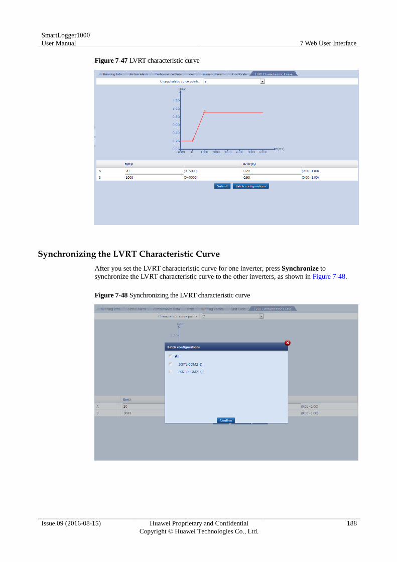
SmartLogger1000
User Manual 7 Web User Interface
Issue 09 (2016-08-15) Huawei Proprietary and Confidential
Copyright © Huawei Technologies Co., Ltd.
188
Figure 7-47 LVRT characteristic curve
Synchronizing the LVRT Characteristic Curve
After you set the LVRT characteristic curve for one inverter, press Synchronize to
synchronize the LVRT characteristic curve to the other inverters, as shown in Figure 7-48.
Figure 7-48 Synchronizing the LVRT characteristic curve
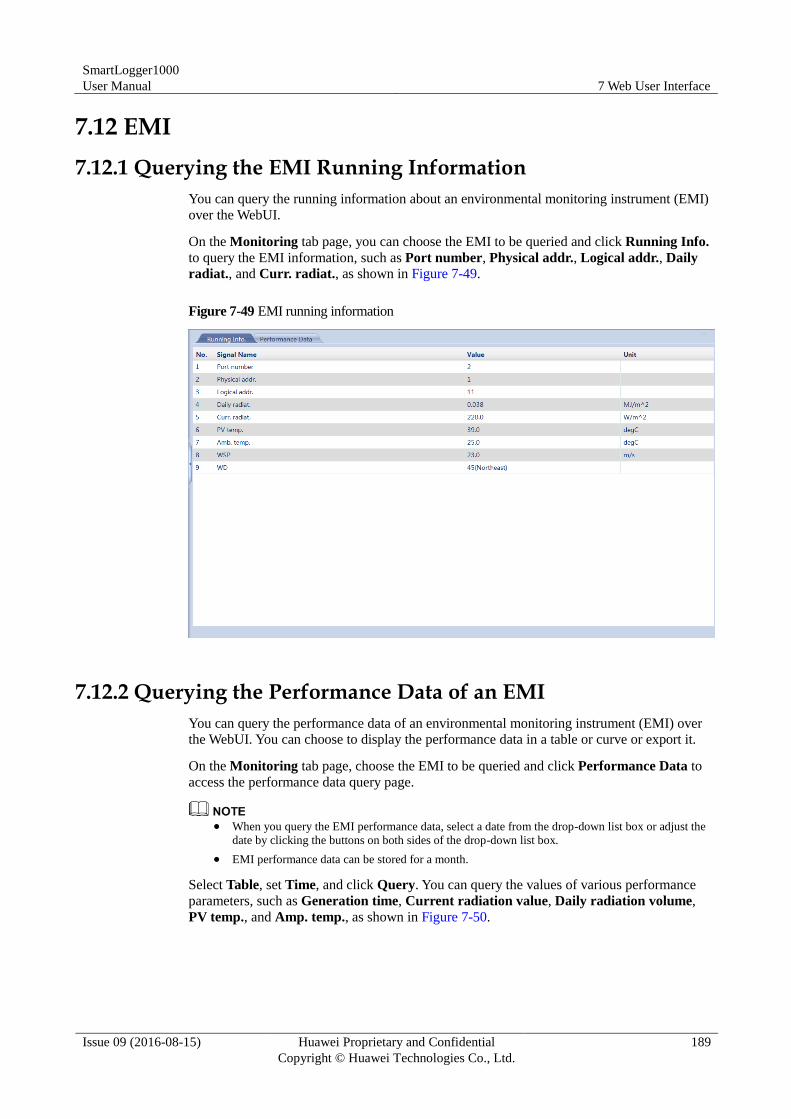
SmartLogger1000
User Manual 7 Web User Interface
Issue 09 (2016-08-15) Huawei Proprietary and Confidential
Copyright © Huawei Technologies Co., Ltd.
189
7.12 EMI
7.12.1 Querying the EMI Running Information
You can query the running information about an environmental monitoring instrument (EMI)
over the WebUI.
On the Monitoring tab page, you can choose the EMI to be queried and click Running Info.
to query the EMI information, such as Port number, Physical addr., Logical addr., Daily
radiat., and Curr. radiat., as shown in Figure 7-49.
Figure 7-49 EMI running information
7.12.2 Querying the Performance Data of an EMI
You can query the performance data of an environmental monitoring instrument (EMI) over
the WebUI. You can choose to display the performance data in a table or curve or export it.
On the Monitoring tab page, choose the EMI to be queried and click Performance Data to
access the performance data query page.
When you query the EMI performance data, select a date from the drop-down list box or adjust the
date by clicking the buttons on both sides of the drop-down list box.
EMI performance data can be stored for a month.
Select Table, set Time, and click Query. You can query the values of various performance
parameters, such as Generation time, Current radiation value, Daily radiation volume,
PV temp., and Amp. temp., as shown in Figure 7-50.
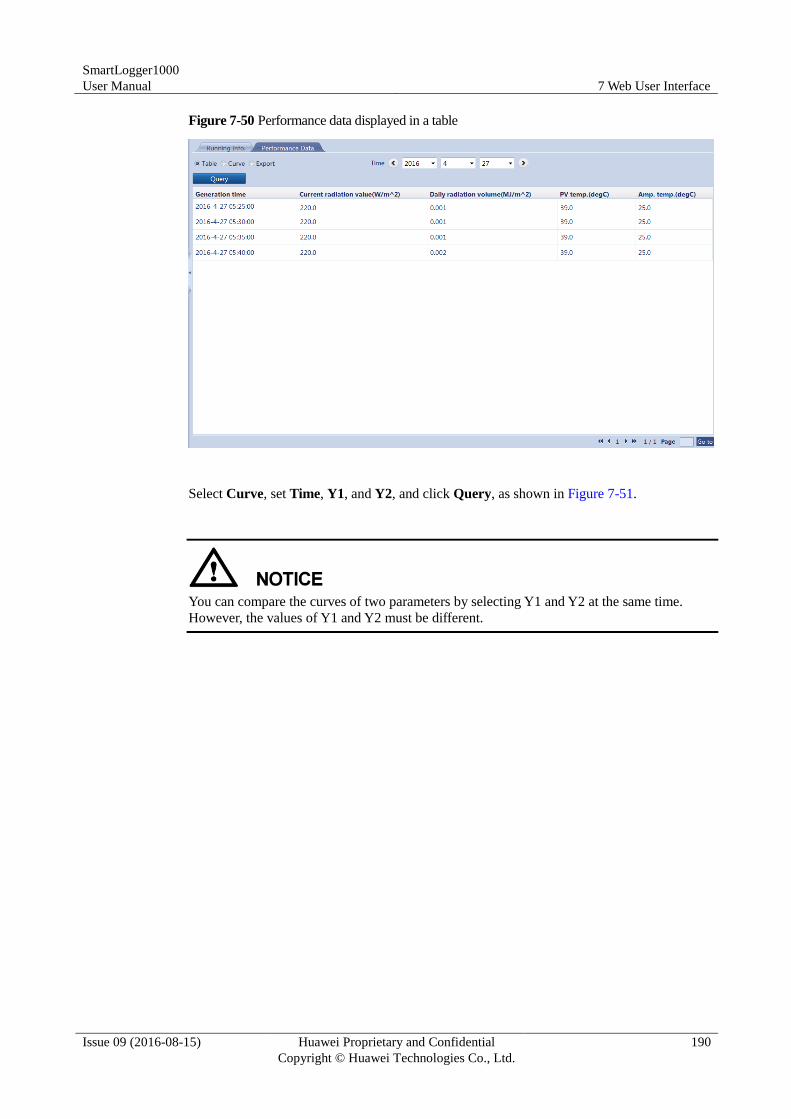
SmartLogger1000
User Manual 7 Web User Interface
Issue 09 (2016-08-15) Huawei Proprietary and Confidential
Copyright © Huawei Technologies Co., Ltd.
190
Figure 7-50 Performance data displayed in a table
Select Curve, set Time, Y1, and Y2, and click Query, as shown in Figure 7-51.
You can compare the curves of two parameters by selecting Y1 and Y2 at the same time.
However, the values of Y1 and Y2 must be different.
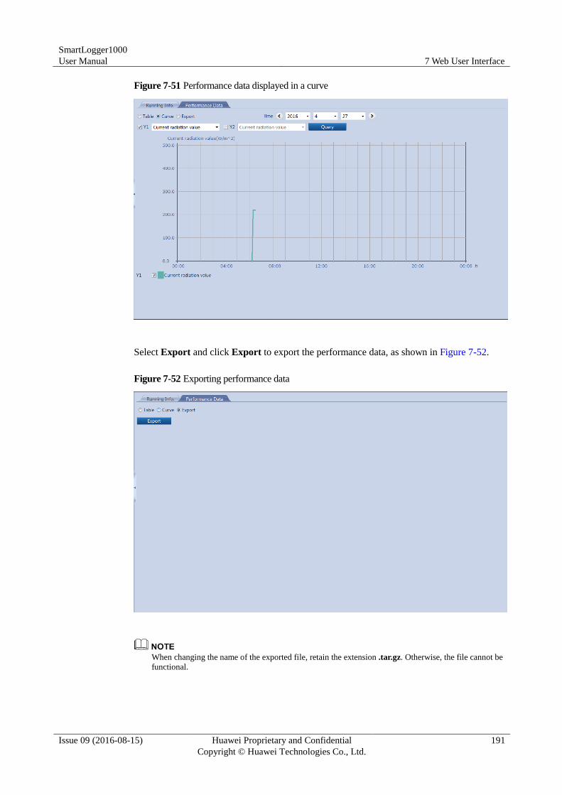
SmartLogger1000
User Manual 7 Web User Interface
Issue 09 (2016-08-15) Huawei Proprietary and Confidential
Copyright © Huawei Technologies Co., Ltd.
191
Figure 7-51 Performance data displayed in a curve
Select Export and click Export to export the performance data, as shown in Figure 7-52.
Figure 7-52 Exporting performance data
When changing the name of the exported file, retain the extension .tar.gz. Otherwise, the file cannot be
functional.
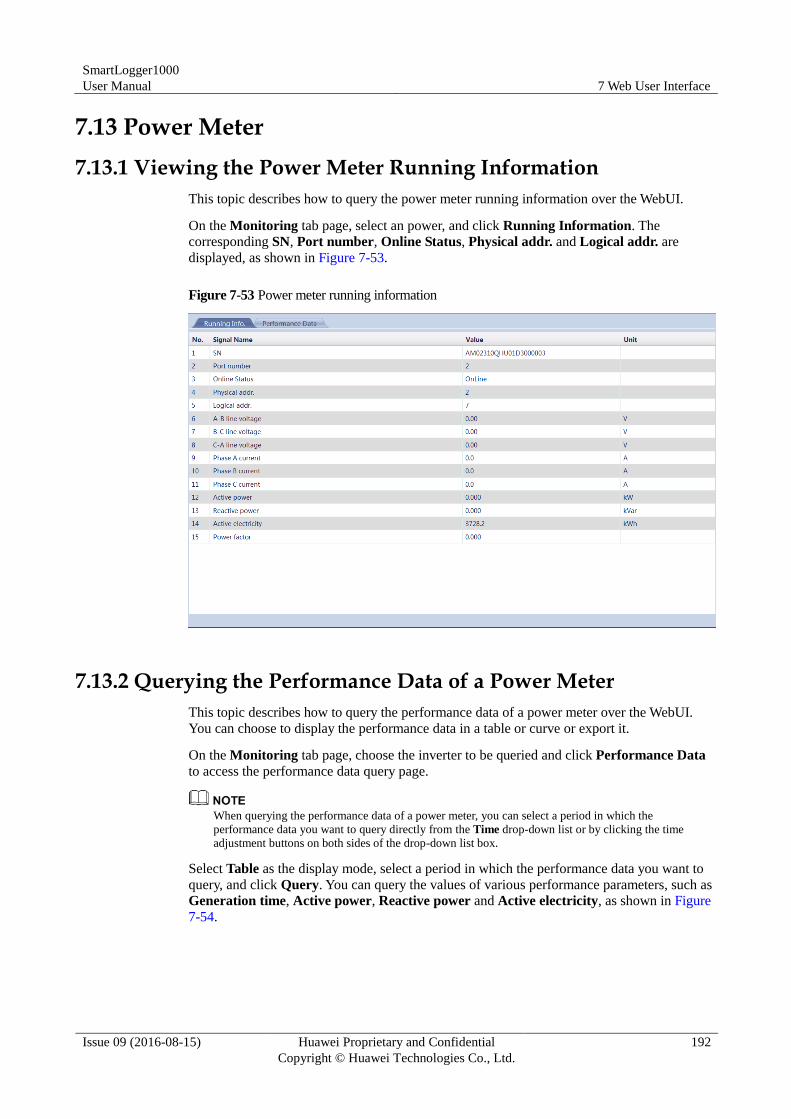
SmartLogger1000
User Manual 7 Web User Interface
Issue 09 (2016-08-15) Huawei Proprietary and Confidential
Copyright © Huawei Technologies Co., Ltd.
192
7.13 Power Meter
7.13.1 Viewing the Power Meter Running Information
This topic describes how to query the power meter running information over the WebUI.
On the Monitoring tab page, select an power, and click Running Information. The
corresponding SN, Port number, Online Status, Physical addr. and Logical addr. are
displayed, as shown in Figure 7-53.
Figure 7-53 Power meter running information
7.13.2 Querying the Performance Data of a Power Meter
This topic describes how to query the performance data of a power meter over the WebUI.
You can choose to display the performance data in a table or curve or export it.
On the Monitoring tab page, choose the inverter to be queried and click Performance Data
to access the performance data query page.
When querying the performance data of a power meter, you can select a period in which the
performance data you want to query directly from the Time drop-down list or by clicking the time
adjustment buttons on both sides of the drop-down list box.
Select Table as the display mode, select a period in which the performance data you want to
query, and click Query. You can query the values of various performance parameters, such as
Generation time, Active power, Reactive power and Active electricity, as shown in Figure
7-54.
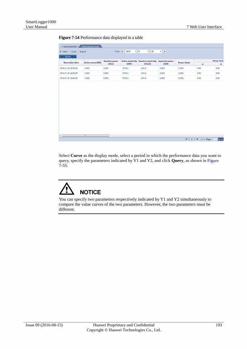
SmartLogger1000
User Manual 7 Web User Interface
Issue 09 (2016-08-15) Huawei Proprietary and Confidential
Copyright © Huawei Technologies Co., Ltd.
193
Figure 7-54 Performance data displayed in a table
Select Curve as the display mode, select a period in which the performance data you want to
query, specify the parameters indicated by Y1 and Y2, and click Query, as shown in Figure
7-55.
You can specify two parameters respectively indicated by Y1 and Y2 simultaneously to
compare the value curves of the two parameters. However, the two parameters must be
different.
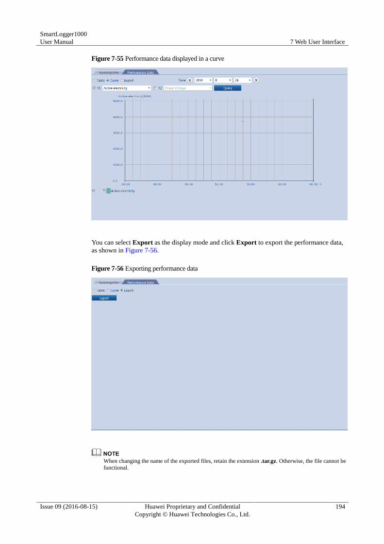
SmartLogger1000
User Manual 7 Web User Interface
Issue 09 (2016-08-15) Huawei Proprietary and Confidential
Copyright © Huawei Technologies Co., Ltd.
194
Figure 7-55 Performance data displayed in a curve
You can select Export as the display mode and click Export to export the performance data,
as shown in Figure 7-56.
Figure 7-56 Exporting performance data
When changing the name of the exported files, retain the extension .tar.gz. Otherwise, the file cannot be
functional.
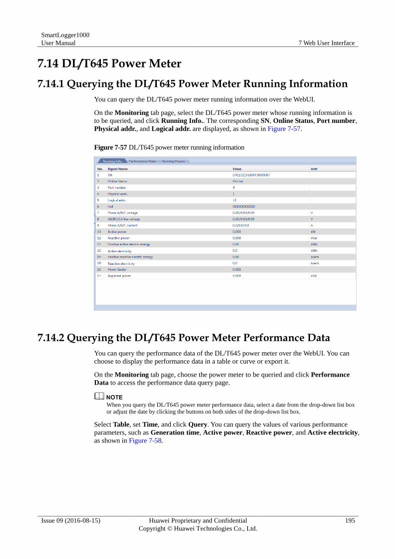
SmartLogger1000
User Manual 7 Web User Interface
Issue 09 (2016-08-15) Huawei Proprietary and Confidential
Copyright © Huawei Technologies Co., Ltd.
195
7.14 DL/T645 Power Meter
7.14.1 Querying the DL/T645 Power Meter Running Information
You can query the DL/T645 power meter running information over the WebUI.
On the Monitoring tab page, select the DL/T645 power meter whose running information is
to be queried, and click Running Info.. The corresponding SN, Online Status, Port number,
Physical addr., and Logical addr. are displayed, as shown in Figure 7-57.
Figure 7-57 DL/T645 power meter running information
7.14.2 Querying the DL/T645 Power Meter Performance Data
You can query the performance data of the DL/T645 power meter over the WebUI. You can
choose to display the performance data in a table or curve or export it.
On the Monitoring tab page, choose the power meter to be queried and click Performance
Data to access the performance data query page.
When you query the DL/T645 power meter performance data, select a date from the drop-down list box
or adjust the date by clicking the buttons on both sides of the drop-down list box.
Select Table, set Time, and click Query. You can query the values of various performance
parameters, such as Generation time, Active power, Reactive power, and Active electricity,
as shown in Figure 7-58.
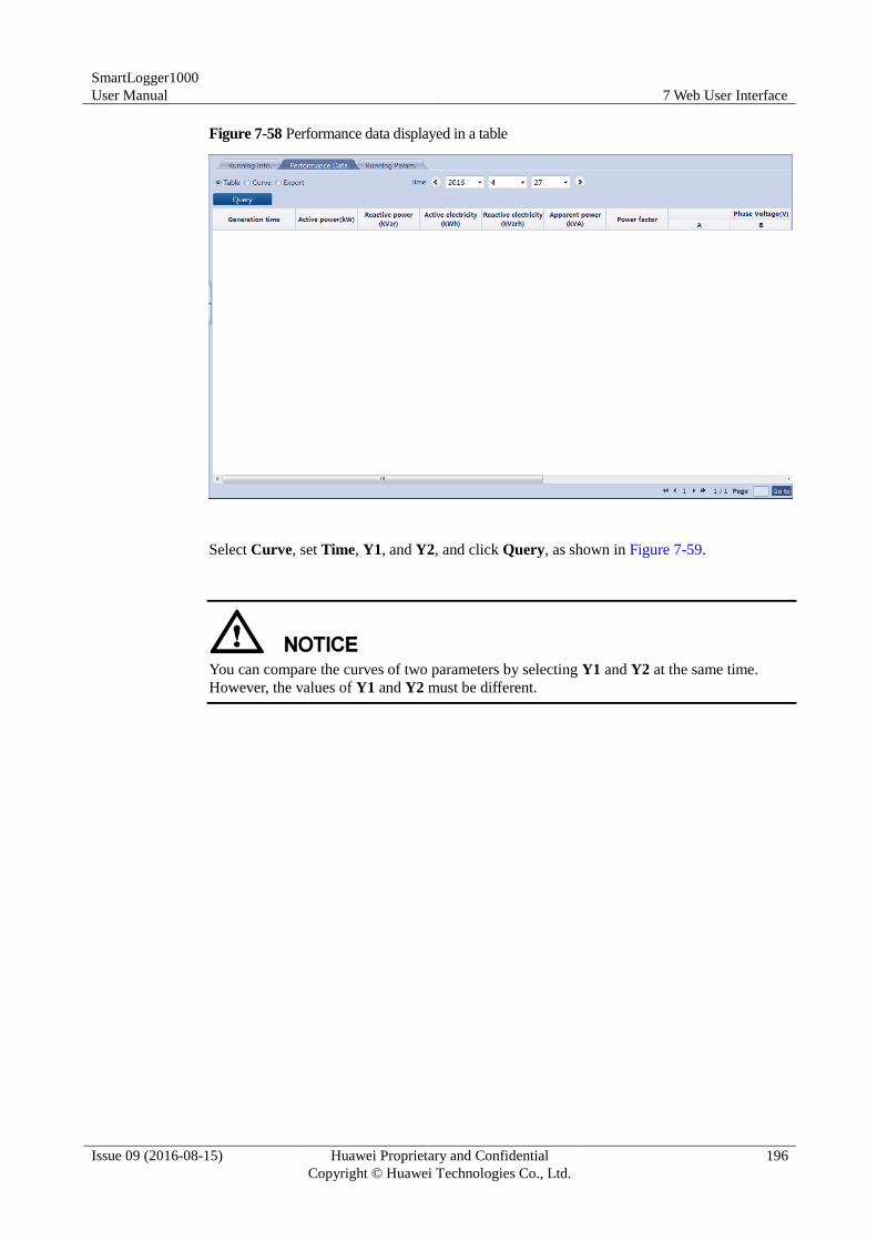
SmartLogger1000
User Manual 7 Web User Interface
Issue 09 (2016-08-15) Huawei Proprietary and Confidential
Copyright © Huawei Technologies Co., Ltd.
196
Figure 7-58 Performance data displayed in a table
Select Curve, set Time, Y1, and Y2, and click Query, as shown in Figure 7-59.
You can compare the curves of two parameters by selecting Y1 and Y2 at the same time.
However, the values of Y1 and Y2 must be different.
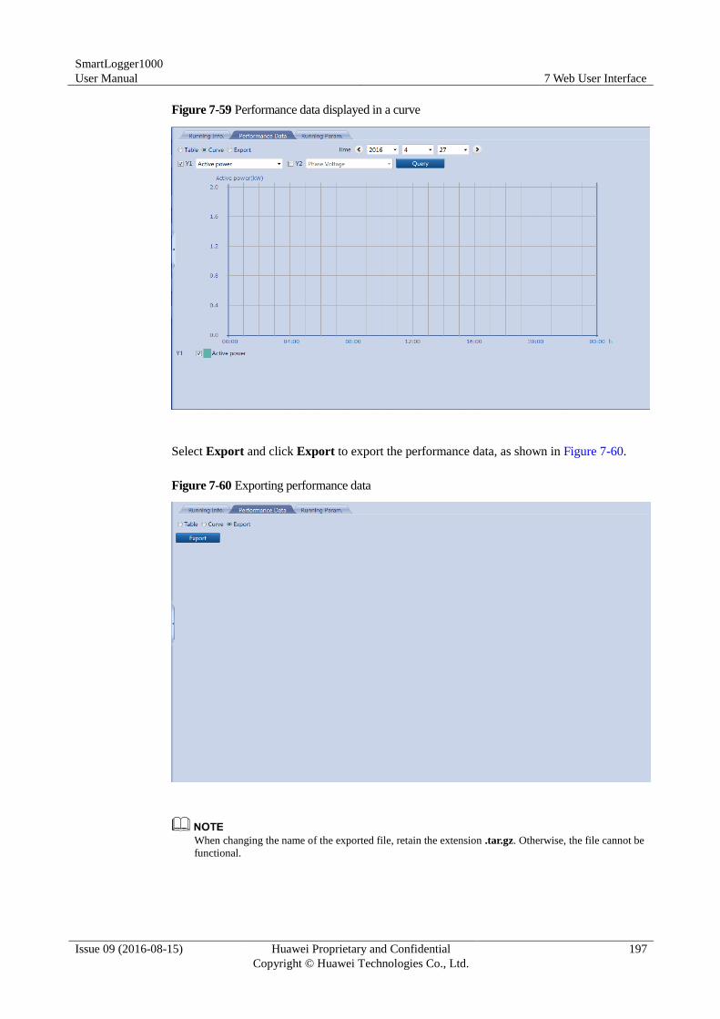
SmartLogger1000
User Manual 7 Web User Interface
Issue 09 (2016-08-15) Huawei Proprietary and Confidential
Copyright © Huawei Technologies Co., Ltd.
197
Figure 7-59 Performance data displayed in a curve
Select Export and click Export to export the performance data, as shown in Figure 7-60.
Figure 7-60 Exporting performance data
When changing the name of the exported file, retain the extension .tar.gz. Otherwise, the file cannot be
functional.
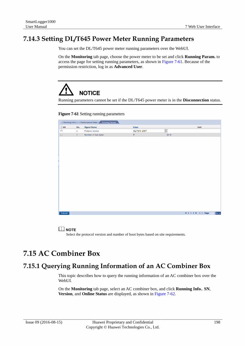
SmartLogger1000
User Manual 7 Web User Interface
Issue 09 (2016-08-15) Huawei Proprietary and Confidential
Copyright © Huawei Technologies Co., Ltd.
198
7.14.3 Setting DL/T645 Power Meter Running Parameters
You can set the DL/T645 power meter running parameters over the WebUI.
On the Monitoring tab page, choose the power meter to be set and click Running Param. to
access the page for setting running parameters, as shown in Figure 7-61. Because of the
permission restriction, log in as Advanced User.
Running parameters cannot be set if the DL/T645 power meter is in the Disconnection status.
Figure 7-61 Setting running parameters
Select the protocol version and number of boot bytes based on site requirements.
7.15 AC Combiner Box
7.15.1 Querying Running Information of an AC Combiner Box
This topic describes how to query the running information of an AC combiner box over the
WebUI.
On the Monitoring tab page, select an AC combiner box, and click Running Info.. SN,
Version, and Online Status are displayed, as shown in Figure 7-62.
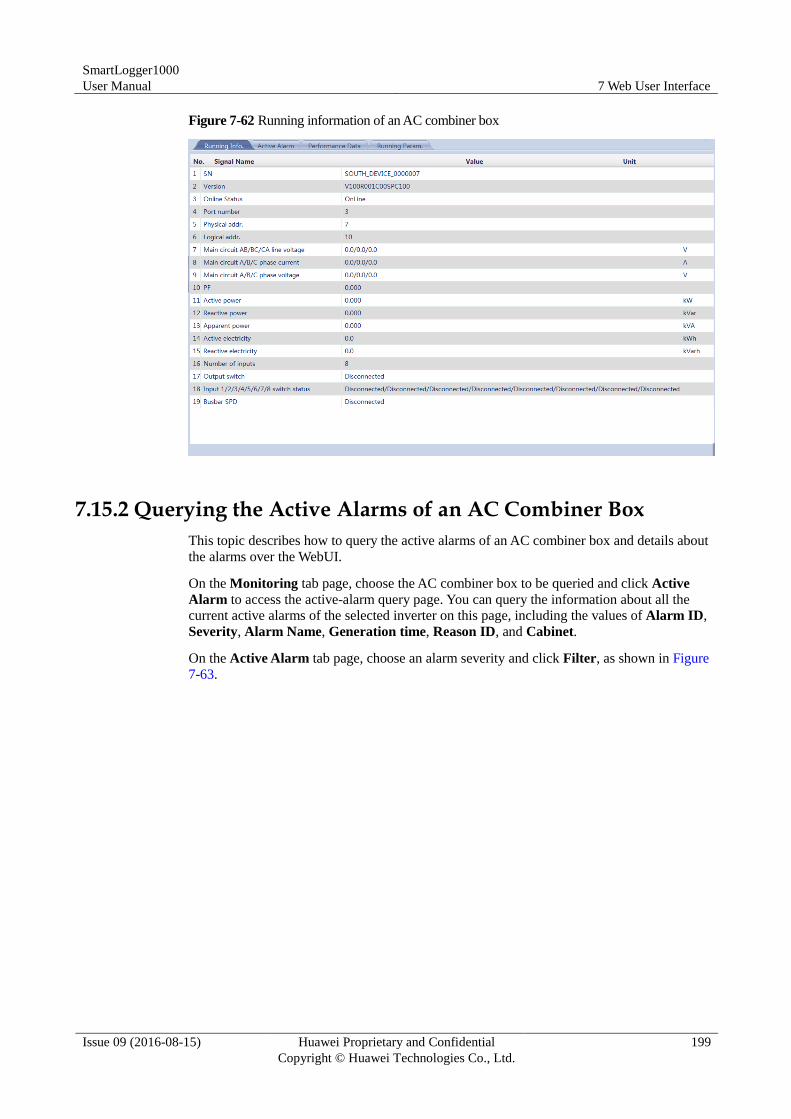
SmartLogger1000
User Manual 7 Web User Interface
Issue 09 (2016-08-15) Huawei Proprietary and Confidential
Copyright © Huawei Technologies Co., Ltd.
199
Figure 7-62 Running information of an AC combiner box
7.15.2 Querying the Active Alarms of an AC Combiner Box
This topic describes how to query the active alarms of an AC combiner box and details about
the alarms over the WebUI.
On the Monitoring tab page, choose the AC combiner box to be queried and click Active
Alarm to access the active-alarm query page. You can query the information about all the
current active alarms of the selected inverter on this page, including the values of Alarm ID,
Severity, Alarm Name, Generation time, Reason ID, and Cabinet.
On the Active Alarm tab page, choose an alarm severity and click Filter, as shown in Figure
7-63.
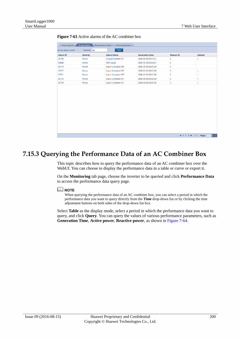
SmartLogger1000
User Manual 7 Web User Interface
Issue 09 (2016-08-15) Huawei Proprietary and Confidential
Copyright © Huawei Technologies Co., Ltd.
200
Figure 7-63 Active alarms of the AC combiner box
7.15.3 Querying the Performance Data of an AC Combiner Box
This topic describes how to query the performance data of an AC combiner box over the
WebUI. You can choose to display the performance data in a table or curve or export it.
On the Monitoring tab page, choose the inverter to be queried and click Performance Data
to access the performance data query page.
When querying the performance data of an AC combiner box, you can select a period in which the
performance data you want to query directly from the Time drop-down list or by clicking the time
adjustment buttons on both sides of the drop-down list box.
Select Table as the display mode, select a period in which the performance data you want to
query, and click Query. You can query the values of various performance parameters, such as
Generation Time, Active power, Reactive power, as shown in Figure 7-64.
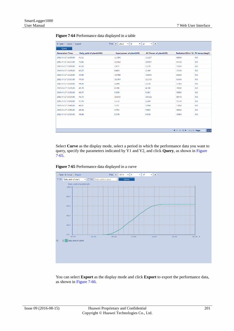
SmartLogger1000
User Manual 7 Web User Interface
Issue 09 (2016-08-15) Huawei Proprietary and Confidential
Copyright © Huawei Technologies Co., Ltd.
201
Figure 7-64 Performance data displayed in a table
Select Curve as the display mode, select a period in which the performance data you want to
query, specify the parameters indicated by Y1 and Y2, and click Query, as shown in Figure
7-65.
Figure 7-65 Performance data displayed in a curve
You can select Export as the display mode and click Export to export the performance data,
as shown in Figure 7-66.
SmartLogger1000
User Manual 7 Web User Interface
Issue 09 (2016-08-15) Huawei Proprietary and Confidential
Copyright © Huawei Technologies Co., Ltd.
202
Figure 7-66 Exporting performance data
When changing the name of the exported files, retain the extension .tar.gz. Otherwise, the file cannot be
functional.
7.15.4 Setting Running Parameters for an AC Combiner Box
This topic describes how to set running parameters for an AC combiner box over the WebUI.
On the Monitoring tab page, choose the AC combiner box to be set and click Running
Param.. The page for setting running parameters is displayed, as shown in Figure 7-67.
Because of the limited permission, select User name as Advanced User.
You cannot set or synchronize running parameters for an AC combiner box in Disconnection
state.
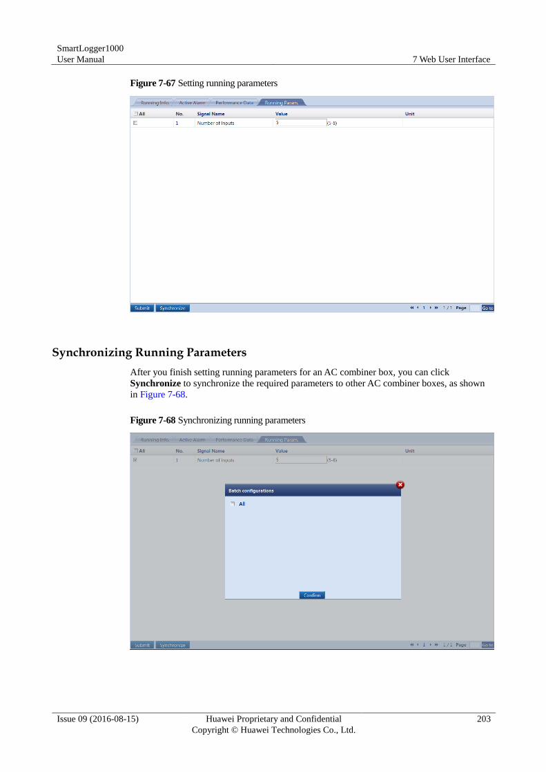
SmartLogger1000
User Manual 7 Web User Interface
Issue 09 (2016-08-15) Huawei Proprietary and Confidential
Copyright © Huawei Technologies Co., Ltd.
203
Figure 7-67 Setting running parameters
Synchronizing Running Parameters
After you finish setting running parameters for an AC combiner box, you can click
Synchronize to synchronize the required parameters to other AC combiner boxes, as shown
in Figure 7-68.
Figure 7-68 Synchronizing running parameters
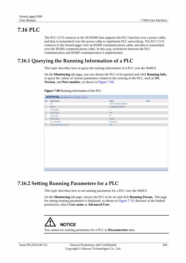
SmartLogger1000
User Manual 7 Web User Interface
Issue 09 (2016-08-15) Huawei Proprietary and Confidential
Copyright © Huawei Technologies Co., Ltd.
204
7.16 PLC
The PLC CCO connects to the SUN2000 that supports the PLC function over a power cable,
and data is transmitted over the power cable to implement PLC networking. The PLC CCO
connects to the SmartLogger over an RS485 communications cable, and data is transmitted
over the RS485 communications cable. In this way, switchover between the PLC
communication and RS485 communication is implemented.
7.16.1 Querying the Running Information of a PLC
This topic describes how to query the running information of a PLC over the WeBUI.
On the Monitoring tab page, you can choose the PLC to be queried and click Running Info.
to query the values of various parameters related to the running of the PLC, such as SN,
Version, and Port number, as shown in Figure 7-69.
Figure 7-69 Running information of the PLC
7.16.2 Setting Running Parameters for a PLC
This topic describes how to set running parameters for a PLC over the WebUI.
On the Monitoring tab page, choose the PLC to be set and click Running Param.. The page
for setting running parameters is displayed, as shown in Figure 7-70. Because of the limited
permission, select User name as Advanced User.
You cannot set running parameters for a PLC in Disconnection state.
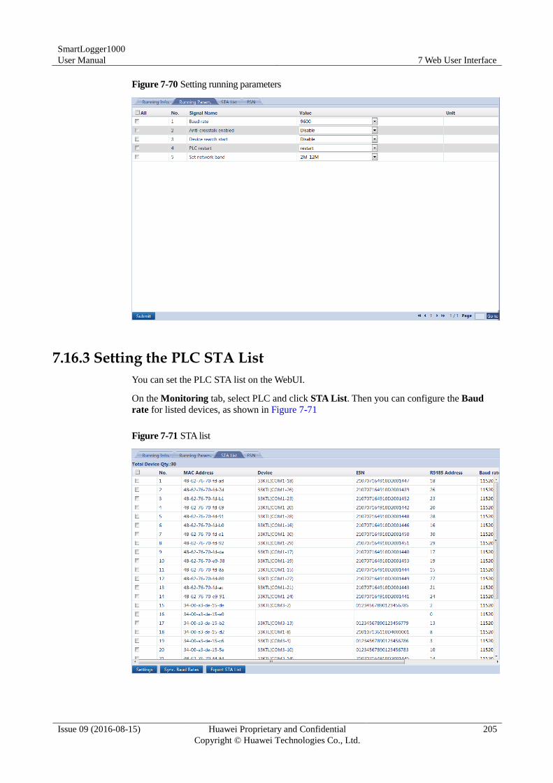
SmartLogger1000
User Manual 7 Web User Interface
Issue 09 (2016-08-15) Huawei Proprietary and Confidential
Copyright © Huawei Technologies Co., Ltd.
205
Figure 7-70 Setting running parameters
7.16.3 Setting the PLC STA List
You can set the PLC STA list on the WebUI.
On the Monitoring tab, select PLC and click STA List. Then you can configure the Baud
rate for listed devices, as shown in Figure 7-71
Figure 7-71 STA list
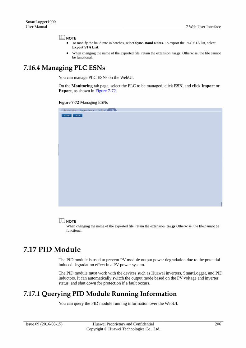
SmartLogger1000
User Manual 7 Web User Interface
Issue 09 (2016-08-15) Huawei Proprietary and Confidential
Copyright © Huawei Technologies Co., Ltd.
206
To modify the baud rate in batches, select Sync. Baud Rates. To export the PLC STA list, select
Export STA List.
When changing the name of the exported file, retain the extension .tar.gz. Otherwise, the file cannot
be functional.
7.16.4 Managing PLC ESNs
You can manage PLC ESNs on the WebUI.
On the Monitoring tab page, select the PLC to be managed, click ESN, and click Import or
Export, as shown in Figure 7-72.
Figure 7-72 Managing ESNs
When changing the name of the exported file, retain the extension .tar.gz Otherwise, the file cannot be
functional.
7.17 PID Module
The PID module is used to prevent PV module output power degradation due to the potential
induced degradation effect in a PV power system.
The PID module must work with the devices such as Huawei inverters, SmartLogger, and PID
inductors. It can automatically switch the output mode based on the PV voltage and inverter
status, and shut down for protection if a fault occurs.
7.17.1 Querying PID Module Running Information
You can query the PID module running information over the WebUI.
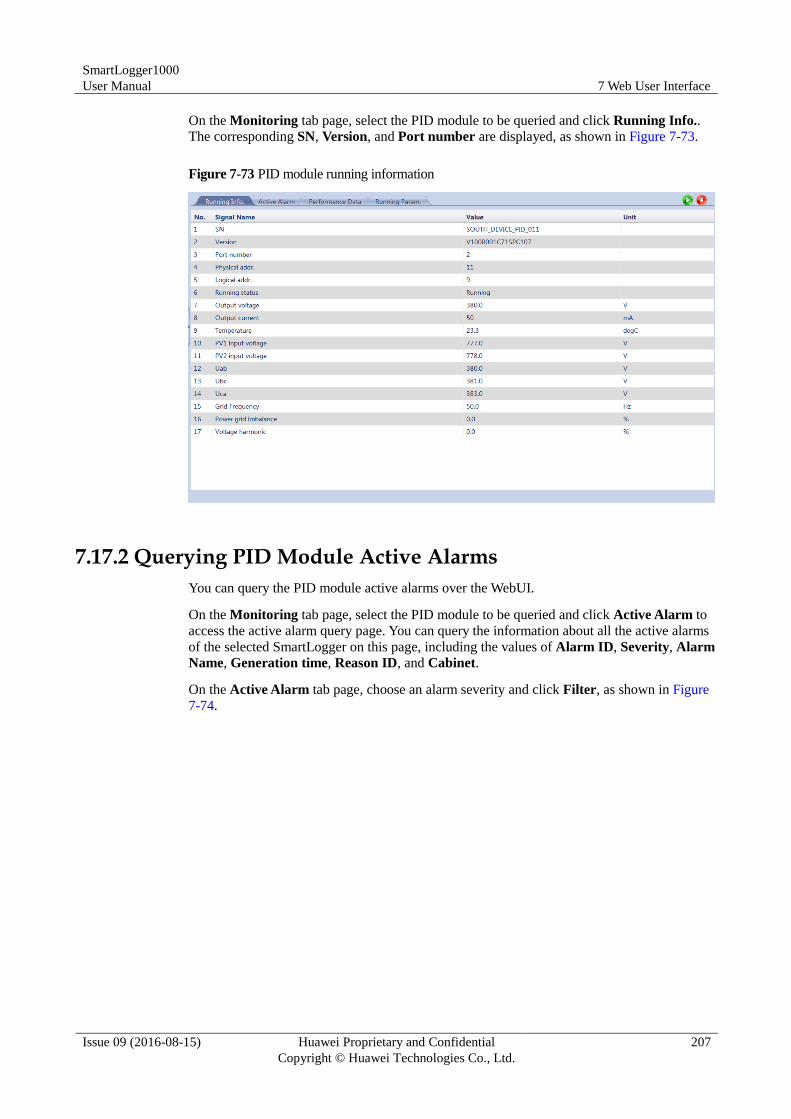
SmartLogger1000
User Manual 7 Web User Interface
Issue 09 (2016-08-15) Huawei Proprietary and Confidential
Copyright © Huawei Technologies Co., Ltd.
207
On the Monitoring tab page, select the PID module to be queried and click Running Info..
The corresponding SN, Version, and Port number are displayed, as shown in Figure 7-73.
Figure 7-73 PID module running information
7.17.2 Querying PID Module Active Alarms
You can query the PID module active alarms over the WebUI.
On the Monitoring tab page, select the PID module to be queried and click Active Alarm to
access the active alarm query page. You can query the information about all the active alarms
of the selected SmartLogger on this page, including the values of Alarm ID, Severity, Alarm
Name, Generation time, Reason ID, and Cabinet.
On the Active Alarm tab page, choose an alarm severity and click Filter, as shown in Figure
7-74.
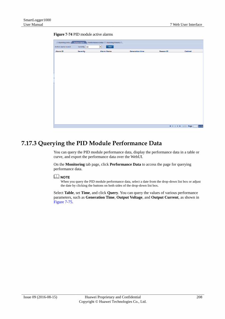
SmartLogger1000
User Manual 7 Web User Interface
Issue 09 (2016-08-15) Huawei Proprietary and Confidential
Copyright © Huawei Technologies Co., Ltd.
208
Figure 7-74 PID module active alarms
7.17.3 Querying the PID Module Performance Data
You can query the PID module performance data, display the performance data in a table or
curve, and export the performance data over the WebUI.
On the Monitoring tab page, click Performance Data to access the page for querying
performance data.
When you query the PID module performance data, select a date from the drop-down list box or adjust
the date by clicking the buttons on both sides of the drop-down list box.
Select Table, set Time, and click Query. You can query the values of various performance
parameters, such as Generation Time, Output Voltage, and Output Current, as shown in
Figure 7-75.
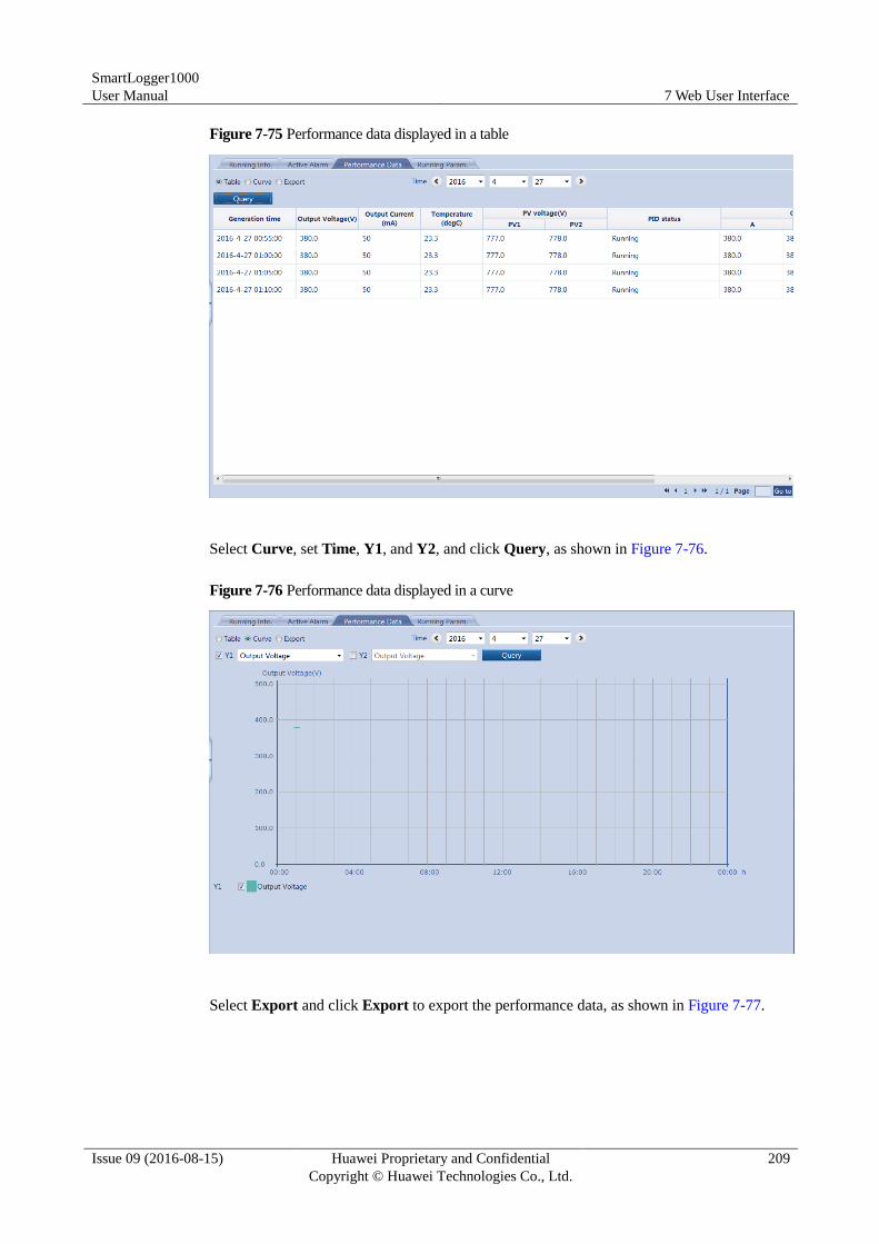
SmartLogger1000
User Manual 7 Web User Interface
Issue 09 (2016-08-15) Huawei Proprietary and Confidential
Copyright © Huawei Technologies Co., Ltd.
209
Figure 7-75 Performance data displayed in a table
Select Curve, set Time, Y1, and Y2, and click Query, as shown in Figure 7-76.
Figure 7-76 Performance data displayed in a curve
Select Export and click Export to export the performance data, as shown in Figure 7-77.
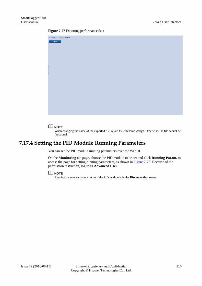
SmartLogger1000
User Manual 7 Web User Interface
Issue 09 (2016-08-15) Huawei Proprietary and Confidential
Copyright © Huawei Technologies Co., Ltd.
210
Figure 7-77 Exporting performance data
When changing the name of the exported file, retain the extension .tar.gz. Otherwise, the file cannot be
functional.
7.17.4 Setting the PID Module Running Parameters
You can set the PID module running parameters over the WebUI.
On the Monitoring tab page, choose the PID module to be set and click Running Param. to
access the page for setting running parameters, as shown in Figure 7-78. Because of the
permission restriction, log in as Advanced User.
Running parameters cannot be set if the PID module is in the Disconnection status.
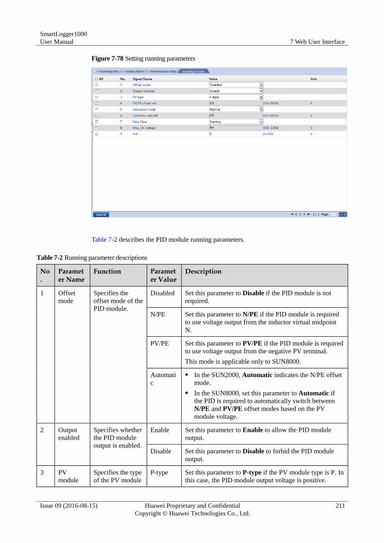
SmartLogger1000
User Manual 7 Web User Interface
Issue 09 (2016-08-15) Huawei Proprietary and Confidential
Copyright © Huawei Technologies Co., Ltd.
211
Figure 7-78 Setting running parameters
Table 7-2 describes the PID module running parameters.
Table 7-2 Running parameter descriptions
No.
Parameter Name
Function Parameter Value
Description
1 Offset
mode
Specifies the
offset mode of the
PID module.
Disabled Set this parameter to Disable if the PID module is not
required.
N/PE Set this parameter to N/PE if the PID module is required
to use voltage output from the inductor virtual midpoint
N.
PV/PE Set this parameter to PV/PE if the PID module is required
to use voltage output from the negative PV terminal.
This mode is applicable only to SUN8000.
Automati
c
In the SUN2000, Automatic indicates the N/PE offset
mode.
In the SUN8000, set this parameter to Automatic if
the PID is required to automatically switch between
N/PE and PV/PE offset modes based on the PV
module voltage.
2 Output
enabled
Specifies whether
the PID module
output is enabled.
Enable Set this parameter to Enable to allow the PID module
output.
Disable Set this parameter to Disable to forbid the PID module
output.
3 PV
module
Specifies the type
of the PV module P-type Set this parameter to P-type if the PV module type is P. In
this case, the PID module output voltage is positive.
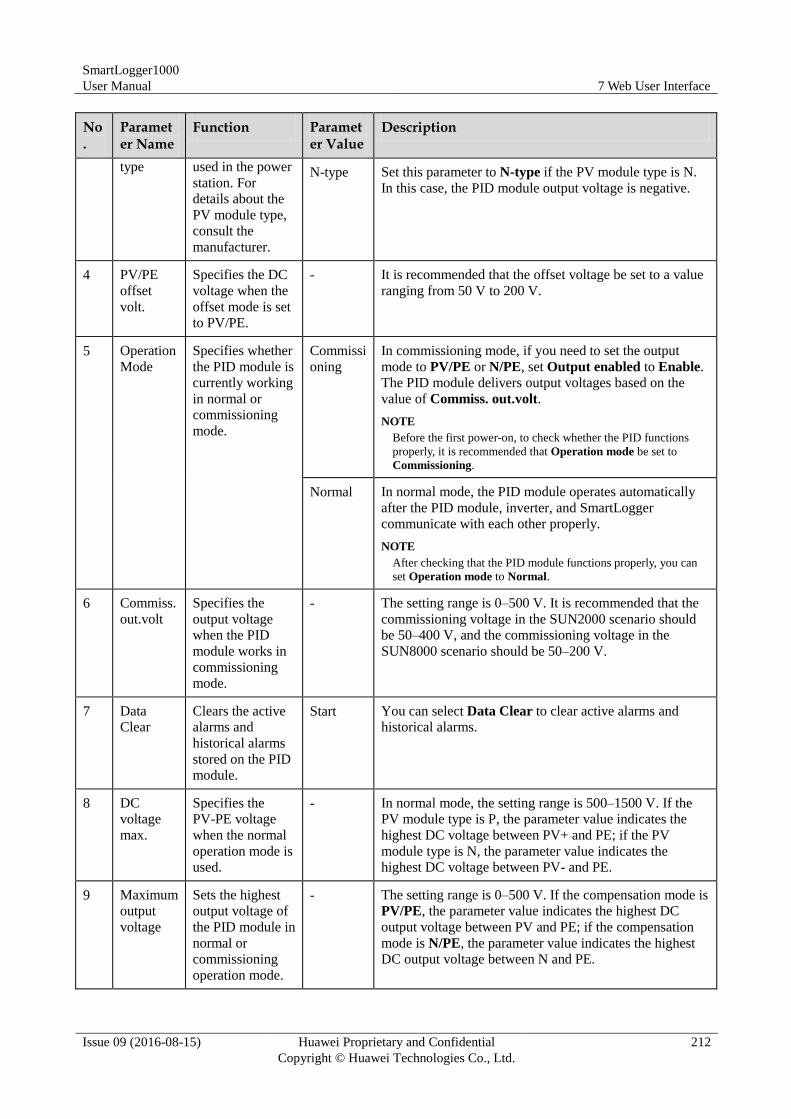
SmartLogger1000
User Manual 7 Web User Interface
Issue 09 (2016-08-15) Huawei Proprietary and Confidential
Copyright © Huawei Technologies Co., Ltd.
212
No.
Parameter Name
Function Parameter Value
Description
type used in the power
station. For
details about the
PV module type,
consult the
manufacturer.
N-type Set this parameter to N-type if the PV module type is N.
In this case, the PID module output voltage is negative.
4 PV/PE
offset
volt.
Specifies the DC
voltage when the
offset mode is set
to PV/PE.
- It is recommended that the offset voltage be set to a value
ranging from 50 V to 200 V.
5 Operation
Mode
Specifies whether
the PID module is
currently working
in normal or
commissioning
mode.
Commissi
oning
In commissioning mode, if you need to set the output
mode to PV/PE or N/PE, set Output enabled to Enable.
The PID module delivers output voltages based on the
value of Commiss. out.volt.
NOTE
Before the first power-on, to check whether the PID functions
properly, it is recommended that Operation mode be set to
Commissioning.
Normal In normal mode, the PID module operates automatically
after the PID module, inverter, and SmartLogger
communicate with each other properly.
NOTE
After checking that the PID module functions properly, you can
set Operation mode to Normal.
6 Commiss.
out.volt
Specifies the
output voltage
when the PID
module works in
commissioning
mode.
- The setting range is 0–500 V. It is recommended that the
commissioning voltage in the SUN2000 scenario should
be 50–400 V, and the commissioning voltage in the
SUN8000 scenario should be 50–200 V.
7 Data
Clear
Clears the active
alarms and
historical alarms
stored on the PID
module.
Start You can select Data Clear to clear active alarms and
historical alarms.
8 DC
voltage
max.
Specifies the
PV-PE voltage
when the normal
operation mode is
used.
- In normal mode, the setting range is 500–1500 V. If the
PV module type is P, the parameter value indicates the
highest DC voltage between PV+ and PE; if the PV
module type is N, the parameter value indicates the
highest DC voltage between PV- and PE.
9 Maximum
output
voltage
Sets the highest
output voltage of
the PID module in
normal or
commissioning
operation mode.
- The setting range is 0–500 V. If the compensation mode is
PV/PE, the parameter value indicates the highest DC
output voltage between PV and PE; if the compensation
mode is N/PE, the parameter value indicates the highest
DC output voltage between N and PE.
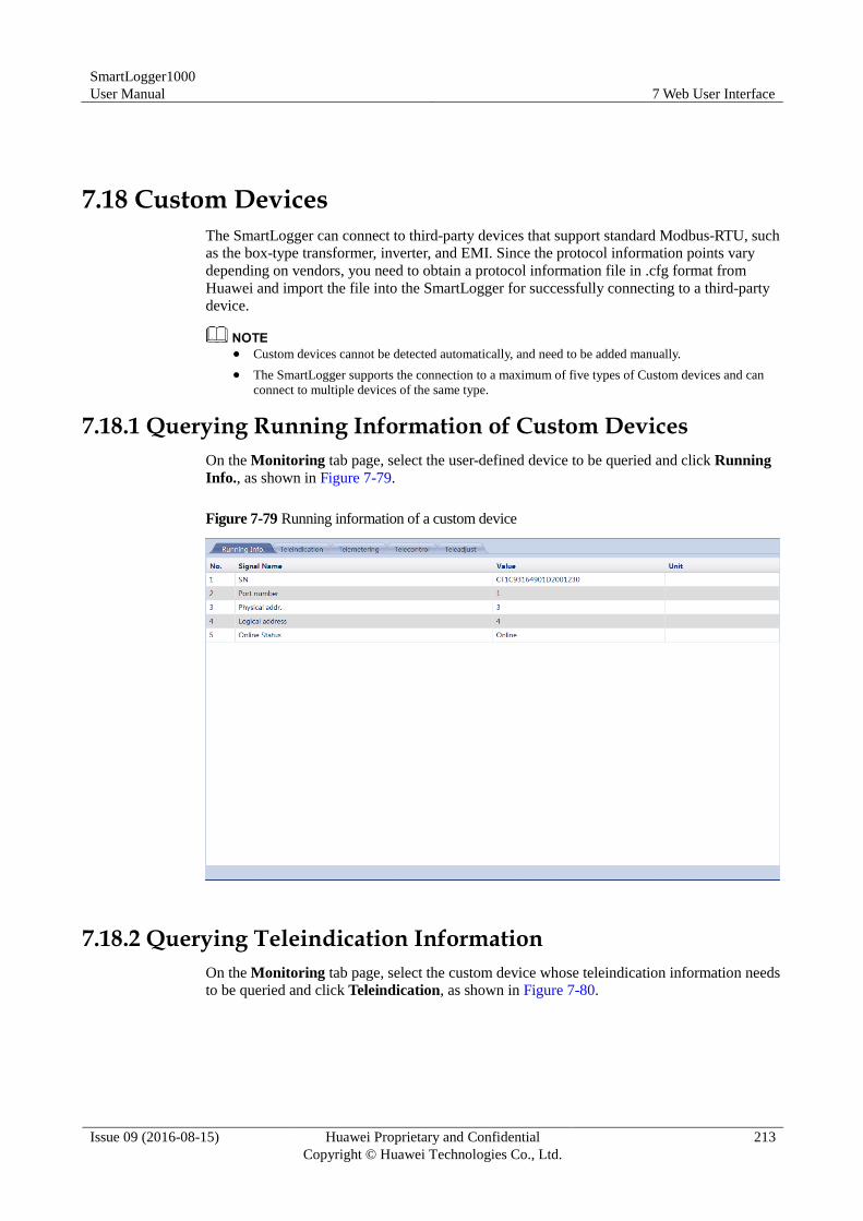
SmartLogger1000
User Manual 7 Web User Interface
Issue 09 (2016-08-15) Huawei Proprietary and Confidential
Copyright © Huawei Technologies Co., Ltd.
213
7.18 Custom Devices
The SmartLogger can connect to third-party devices that support standard Modbus-RTU, such
as the box-type transformer, inverter, and EMI. Since the protocol information points vary
depending on vendors, you need to obtain a protocol information file in .cfg format from
Huawei and import the file into the SmartLogger for successfully connecting to a third-party
device.
Custom devices cannot be detected automatically, and need to be added manually.
The SmartLogger supports the connection to a maximum of five types of Custom devices and can
connect to multiple devices of the same type.
7.18.1 Querying Running Information of Custom Devices
On the Monitoring tab page, select the user-defined device to be queried and click Running
Info., as shown in Figure 7-79.
Figure 7-79 Running information of a custom device
7.18.2 Querying Teleindication Information
On the Monitoring tab page, select the custom device whose teleindication information needs
to be queried and click Teleindication, as shown in Figure 7-80.
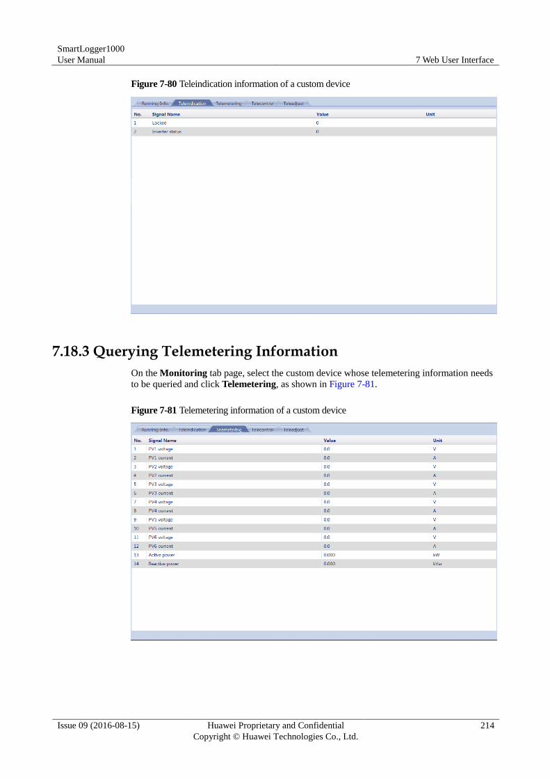
SmartLogger1000
User Manual 7 Web User Interface
Issue 09 (2016-08-15) Huawei Proprietary and Confidential
Copyright © Huawei Technologies Co., Ltd.
214
Figure 7-80 Teleindication information of a custom device
7.18.3 Querying Telemetering Information
On the Monitoring tab page, select the custom device whose telemetering information needs
to be queried and click Telemetering, as shown in Figure 7-81.
Figure 7-81 Telemetering information of a custom device
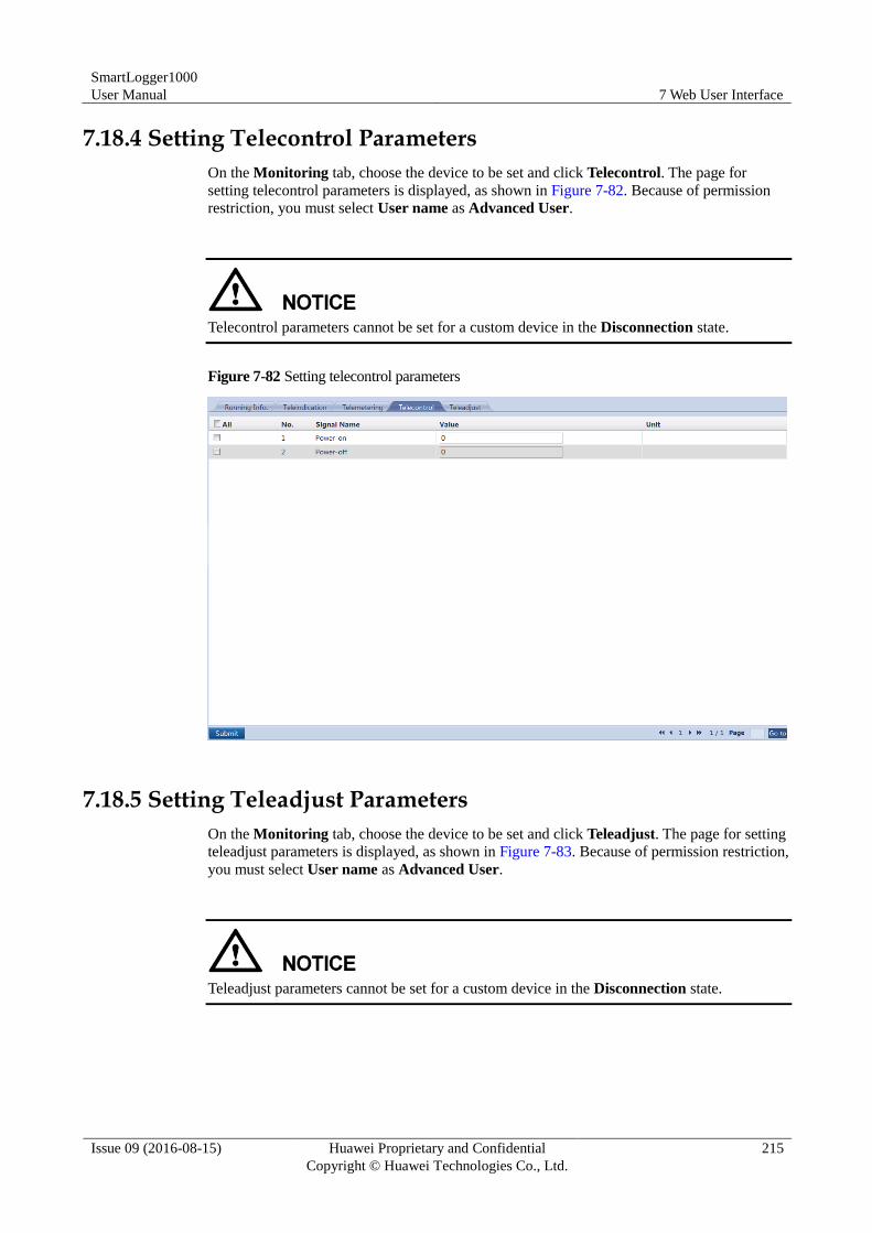
SmartLogger1000
User Manual 7 Web User Interface
Issue 09 (2016-08-15) Huawei Proprietary and Confidential
Copyright © Huawei Technologies Co., Ltd.
215
7.18.4 Setting Telecontrol Parameters
On the Monitoring tab, choose the device to be set and click Telecontrol. The page for
setting telecontrol parameters is displayed, as shown in Figure 7-82. Because of permission
restriction, you must select User name as Advanced User.
Telecontrol parameters cannot be set for a custom device in the Disconnection state.
Figure 7-82 Setting telecontrol parameters
7.18.5 Setting Teleadjust Parameters
On the Monitoring tab, choose the device to be set and click Teleadjust. The page for setting
teleadjust parameters is displayed, as shown in Figure 7-83. Because of permission restriction,
you must select User name as Advanced User.
Teleadjust parameters cannot be set for a custom device in the Disconnection state.
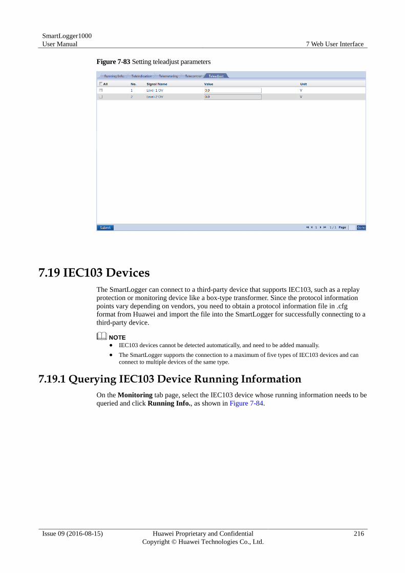
SmartLogger1000
User Manual 7 Web User Interface
Issue 09 (2016-08-15) Huawei Proprietary and Confidential
Copyright © Huawei Technologies Co., Ltd.
216
Figure 7-83 Setting teleadjust parameters
7.19 IEC103 Devices
The SmartLogger can connect to a third-party device that supports IEC103, such as a replay
protection or monitoring device like a box-type transformer. Since the protocol information
points vary depending on vendors, you need to obtain a protocol information file in .cfg
format from Huawei and import the file into the SmartLogger for successfully connecting to a
third-party device.
IEC103 devices cannot be detected automatically, and need to be added manually.
The SmartLogger supports the connection to a maximum of five types of IEC103 devices and can
connect to multiple devices of the same type.
7.19.1 Querying IEC103 Device Running Information
On the Monitoring tab page, select the IEC103 device whose running information needs to be
queried and click Running Info., as shown in Figure 7-84.
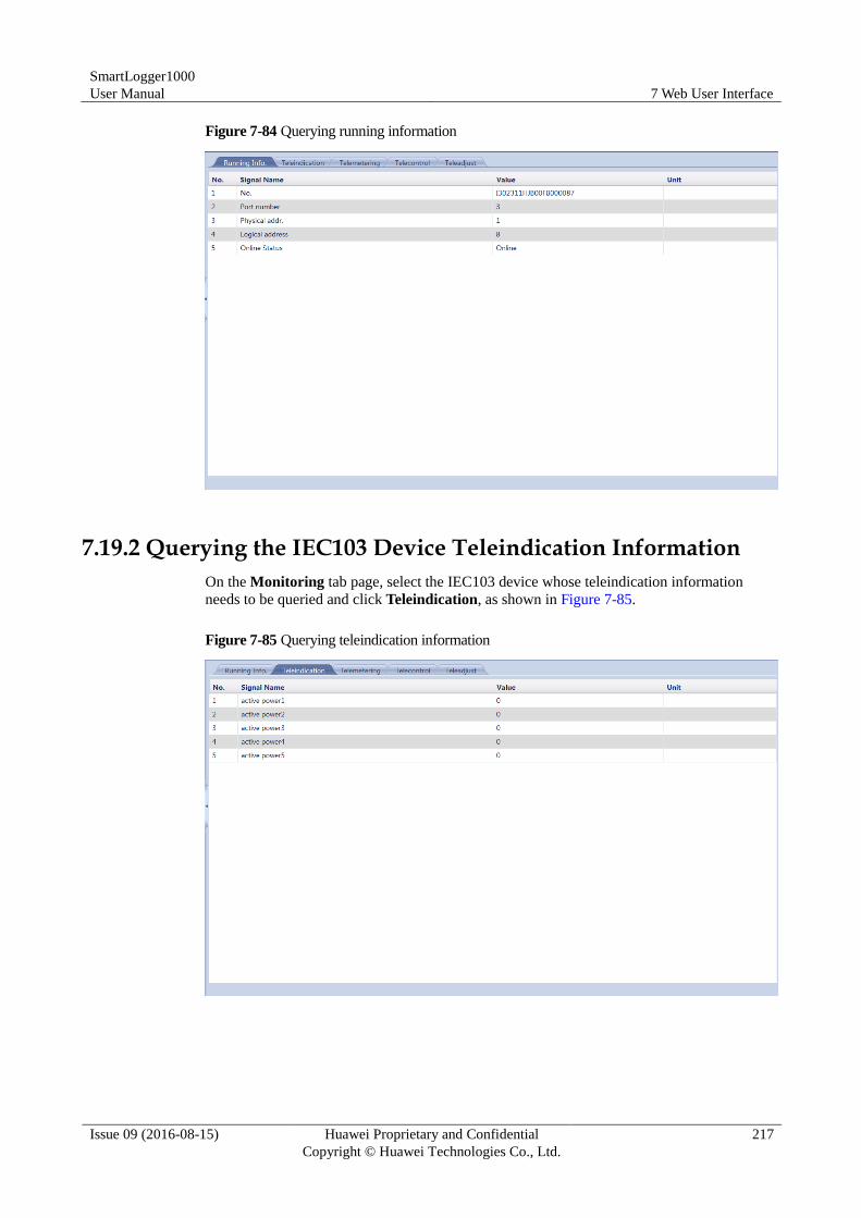
SmartLogger1000
User Manual 7 Web User Interface
Issue 09 (2016-08-15) Huawei Proprietary and Confidential
Copyright © Huawei Technologies Co., Ltd.
217
Figure 7-84 Querying running information
7.19.2 Querying the IEC103 Device Teleindication Information
On the Monitoring tab page, select the IEC103 device whose teleindication information
needs to be queried and click Teleindication, as shown in Figure 7-85.
Figure 7-85 Querying teleindication information
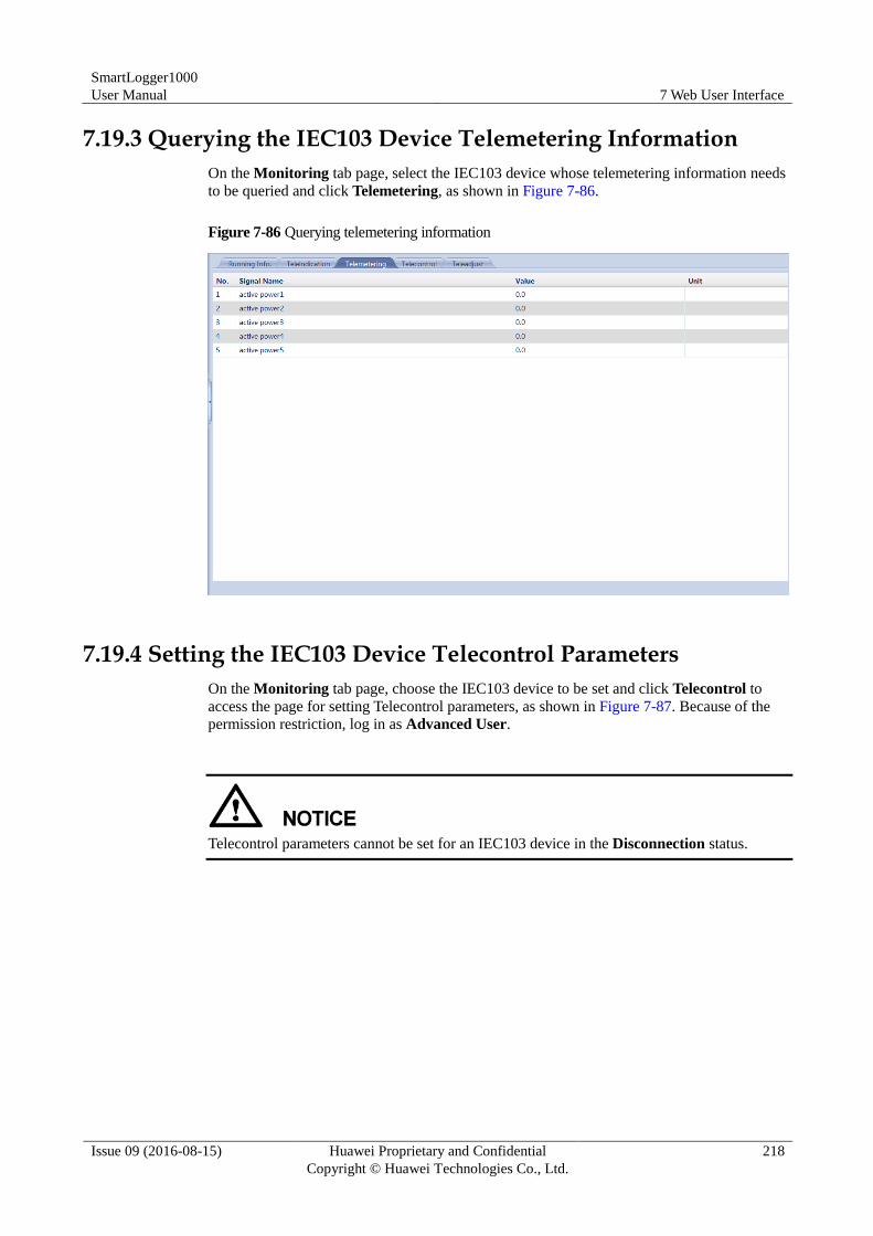
SmartLogger1000
User Manual 7 Web User Interface
Issue 09 (2016-08-15) Huawei Proprietary and Confidential
Copyright © Huawei Technologies Co., Ltd.
218
7.19.3 Querying the IEC103 Device Telemetering Information
On the Monitoring tab page, select the IEC103 device whose telemetering information needs
to be queried and click Telemetering, as shown in Figure 7-86.
Figure 7-86 Querying telemetering information
7.19.4 Setting the IEC103 Device Telecontrol Parameters
On the Monitoring tab page, choose the IEC103 device to be set and click Telecontrol to
access the page for setting Telecontrol parameters, as shown in Figure 7-87. Because of the
permission restriction, log in as Advanced User.
Telecontrol parameters cannot be set for an IEC103 device in the Disconnection status.
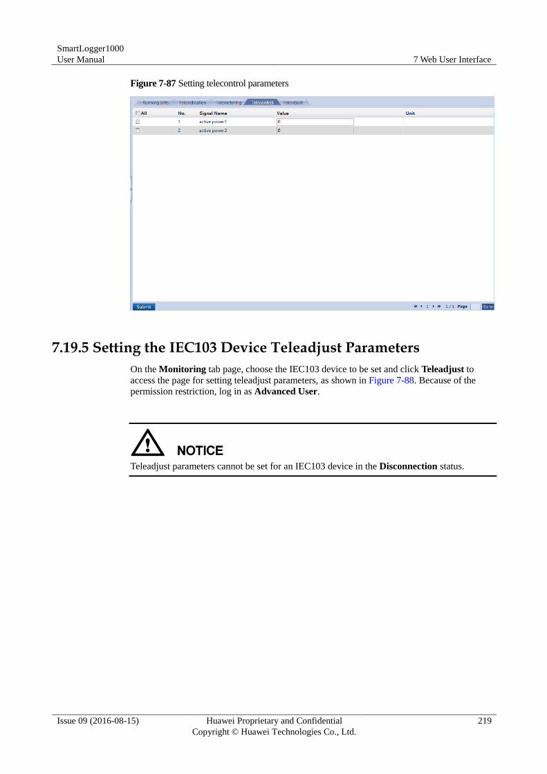
SmartLogger1000
User Manual 7 Web User Interface
Issue 09 (2016-08-15) Huawei Proprietary and Confidential
Copyright © Huawei Technologies Co., Ltd.
219
Figure 7-87 Setting telecontrol parameters
7.19.5 Setting the IEC103 Device Teleadjust Parameters
On the Monitoring tab page, choose the IEC103 device to be set and click Teleadjust to
access the page for setting teleadjust parameters, as shown in Figure 7-88. Because of the
permission restriction, log in as Advanced User.
Teleadjust parameters cannot be set for an IEC103 device in the Disconnection status.
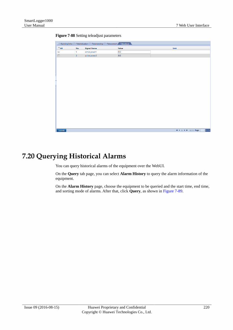
SmartLogger1000
User Manual 7 Web User Interface
Issue 09 (2016-08-15) Huawei Proprietary and Confidential
Copyright © Huawei Technologies Co., Ltd.
220
Figure 7-88 Setting teleadjust parameters
7.20 Querying Historical Alarms
You can query historical alarms of the equipment over the WebUI.
On the Query tab page, you can select Alarm History to query the alarm information of the
equipment.
On the Alarm History page, choose the equipment to be queried and the start time, end time,
and sorting mode of alarms. After that, click Query, as shown in Figure 7-89.
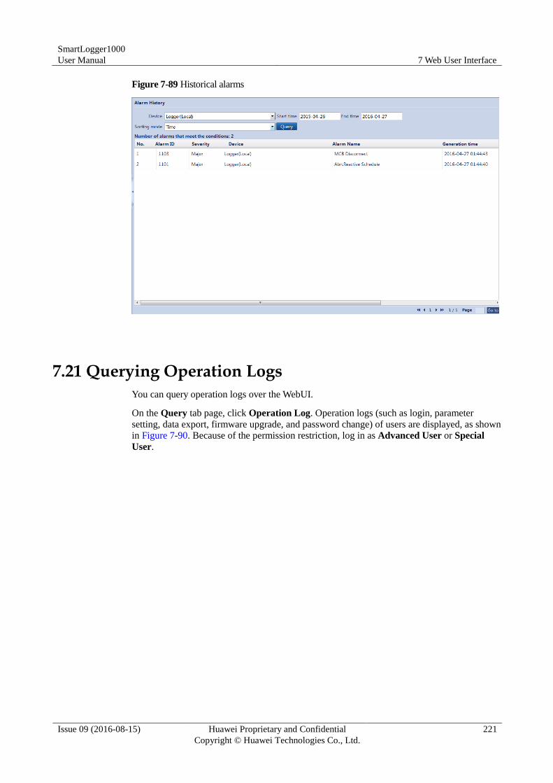
SmartLogger1000
User Manual 7 Web User Interface
Issue 09 (2016-08-15) Huawei Proprietary and Confidential
Copyright © Huawei Technologies Co., Ltd.
221
Figure 7-89 Historical alarms
7.21 Querying Operation Logs
You can query operation logs over the WebUI.
On the Query tab page, click Operation Log. Operation logs (such as login, parameter
setting, data export, firmware upgrade, and password change) of users are displayed, as shown
in Figure 7-90. Because of the permission restriction, log in as Advanced User or Special
User.

SmartLogger1000
User Manual 7 Web User Interface
Issue 09 (2016-08-15) Huawei Proprietary and Confidential
Copyright © Huawei Technologies Co., Ltd.
222
Figure 7-90 Operation log
7.22 Exporting Data
This topic describes how to export historical alarms, energy yield, operation logs and grid
dispatching logs over the WebUI.
Exporting Data
In the Export Data window, you can export Alarm History, Yield, Operation Log, Grid
Dispatching or All in CSV format, as shown in Figure 7-91. Because of the limited
permission, select the User name as Advanced User or Special User.
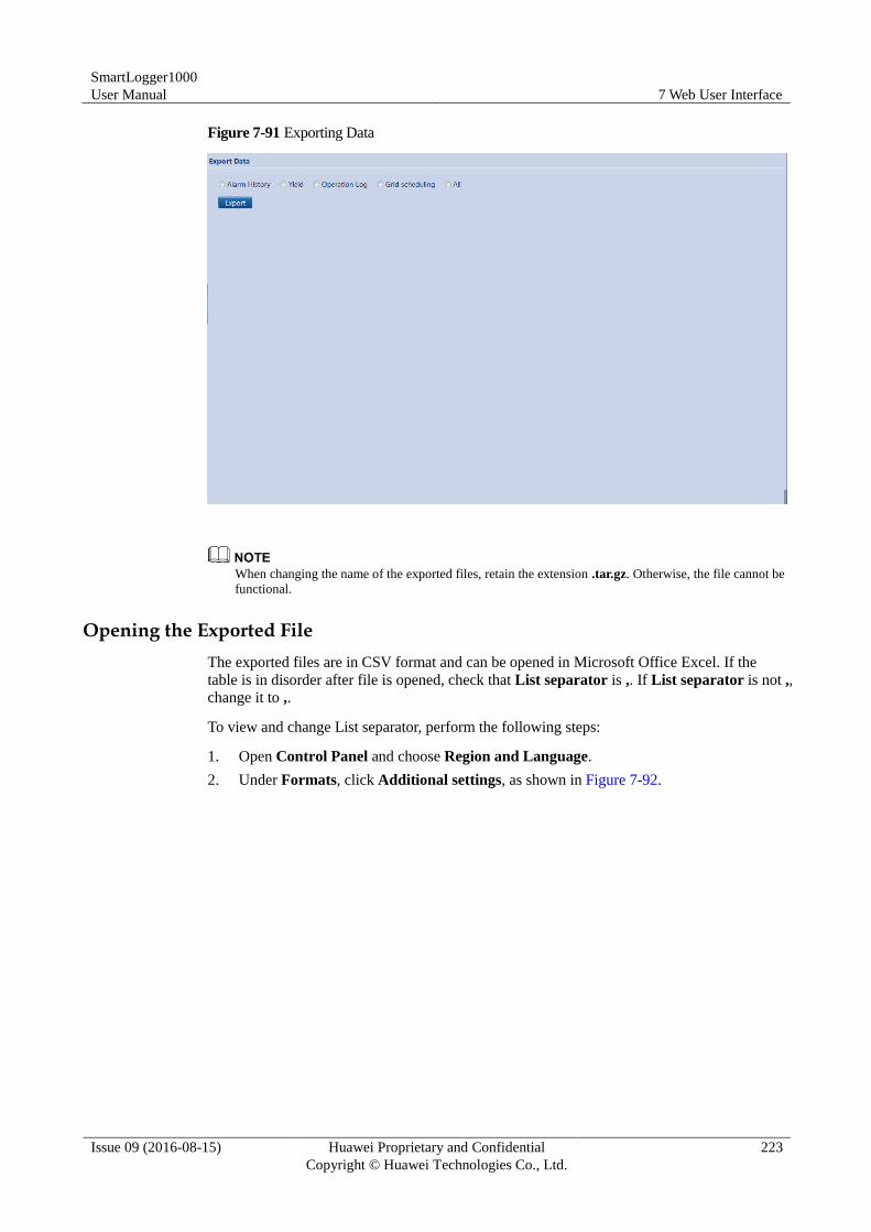
SmartLogger1000
User Manual 7 Web User Interface
Issue 09 (2016-08-15) Huawei Proprietary and Confidential
Copyright © Huawei Technologies Co., Ltd.
223
Figure 7-91 Exporting Data
When changing the name of the exported files, retain the extension .tar.gz. Otherwise, the file cannot be
functional.
Opening the Exported File
The exported files are in CSV format and can be opened in Microsoft Office Excel. If the
table is in disorder after file is opened, check that List separator is ,. If List separator is not ,,
change it to ,.
To view and change List separator, perform the following steps:
1. Open Control Panel and choose Region and Language.
2. Under Formats, click Additional settings, as shown in Figure 7-92.
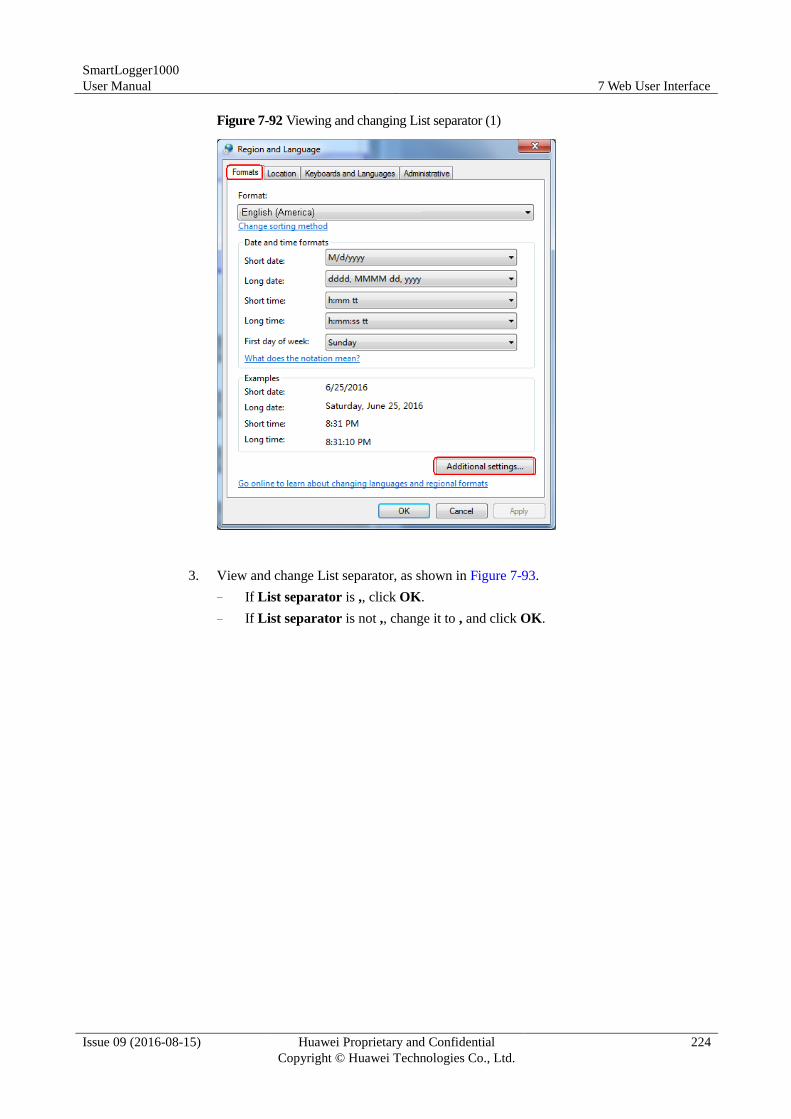
SmartLogger1000
User Manual 7 Web User Interface
Issue 09 (2016-08-15) Huawei Proprietary and Confidential
Copyright © Huawei Technologies Co., Ltd.
224
Figure 7-92 Viewing and changing List separator (1)
3. View and change List separator, as shown in Figure 7-93.
− If List separator is ,, click OK.
− If List separator is not ,, change it to , and click OK.
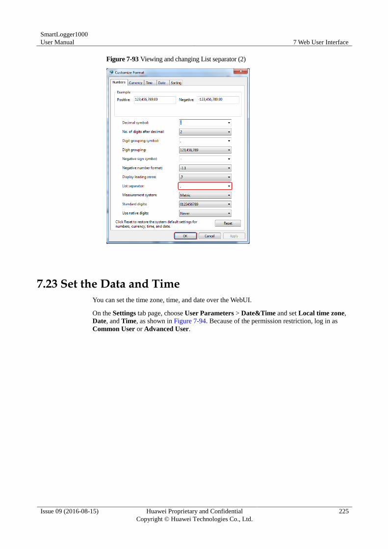
SmartLogger1000
User Manual 7 Web User Interface
Issue 09 (2016-08-15) Huawei Proprietary and Confidential
Copyright © Huawei Technologies Co., Ltd.
225
Figure 7-93 Viewing and changing List separator (2)
7.23 Set the Data and Time
You can set the time zone, time, and date over the WebUI.
On the Settings tab page, choose User Parameters > Date&Time and set Local time zone,
Date, and Time, as shown in Figure 7-94. Because of the permission restriction, log in as
Common User or Advanced User.
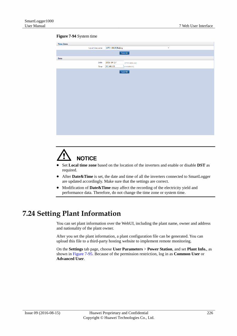
SmartLogger1000
User Manual 7 Web User Interface
Issue 09 (2016-08-15) Huawei Proprietary and Confidential
Copyright © Huawei Technologies Co., Ltd.
226
Figure 7-94 System time
Set Local time zone based on the location of the inverters and enable or disable DST as
required.
After Date&Time is set, the date and time of all the inverters connected to SmartLogger
are updated accordingly. Make sure that the settings are correct.
Modification of Date&Time may affect the recording of the electricity yield and
performance data. Therefore, do not change the time zone or system time.
7.24 Setting Plant Information
You can set plant information over the WebUI, including the plant name, owner and address
and nationality of the plant owner.
After you set the plant information, a plant configuration file can be generated. You can
upload this file to a third-party hosting website to implement remote monitoring.
On the Settings tab page, choose User Parameters > Power Station, and set Plant Info., as
shown in Figure 7-95. Because of the permission restriction, log in as Common User or
Advanced User.
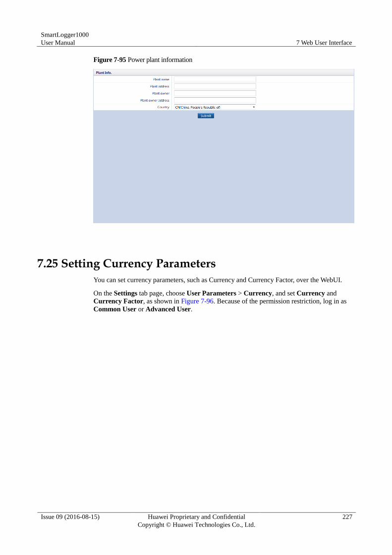
SmartLogger1000
User Manual 7 Web User Interface
Issue 09 (2016-08-15) Huawei Proprietary and Confidential
Copyright © Huawei Technologies Co., Ltd.
227
Figure 7-95 Power plant information
7.25 Setting Currency Parameters
You can set currency parameters, such as Currency and Currency Factor, over the WebUI.
On the Settings tab page, choose User Parameters > Currency, and set Currency and
Currency Factor, as shown in Figure 7-96. Because of the permission restriction, log in as
Common User or Advanced User.
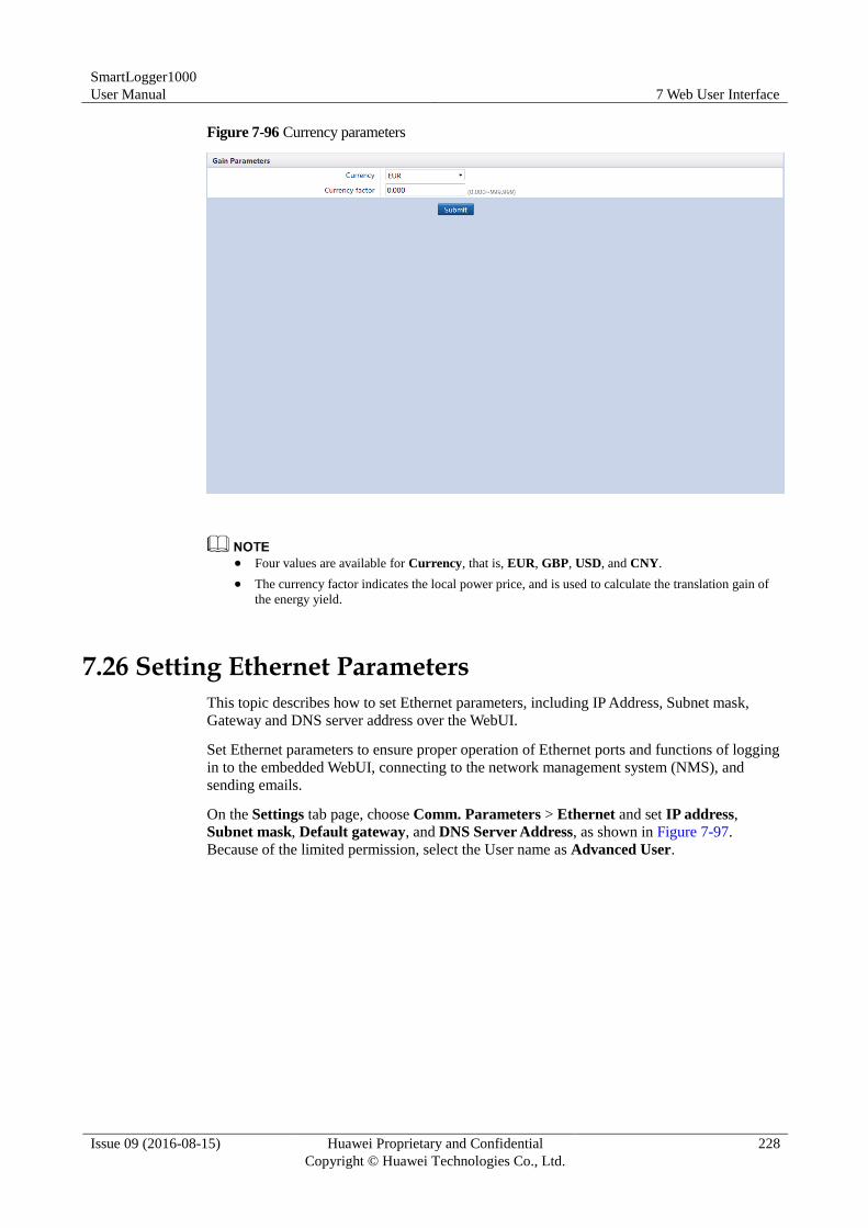
SmartLogger1000
User Manual 7 Web User Interface
Issue 09 (2016-08-15) Huawei Proprietary and Confidential
Copyright © Huawei Technologies Co., Ltd.
228
Figure 7-96 Currency parameters
Four values are available for Currency, that is, EUR, GBP, USD, and CNY.
The currency factor indicates the local power price, and is used to calculate the translation gain of
the energy yield.
7.26 Setting Ethernet Parameters
This topic describes how to set Ethernet parameters, including IP Address, Subnet mask,
Gateway and DNS server address over the WebUI.
Set Ethernet parameters to ensure proper operation of Ethernet ports and functions of logging
in to the embedded WebUI, connecting to the network management system (NMS), and
sending emails.
On the Settings tab page, choose Comm. Parameters > Ethernet and set IP address,
Subnet mask, Default gateway, and DNS Server Address, as shown in Figure 7-97.
Because of the limited permission, select the User name as Advanced User.
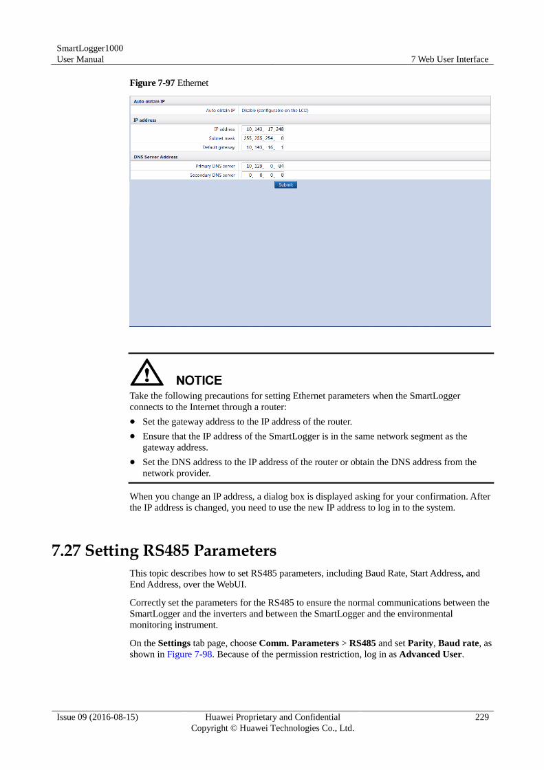
SmartLogger1000
User Manual 7 Web User Interface
Issue 09 (2016-08-15) Huawei Proprietary and Confidential
Copyright © Huawei Technologies Co., Ltd.
229
Figure 7-97 Ethernet
Take the following precautions for setting Ethernet parameters when the SmartLogger
connects to the Internet through a router:
Set the gateway address to the IP address of the router.
Ensure that the IP address of the SmartLogger is in the same network segment as the
gateway address.
Set the DNS address to the IP address of the router or obtain the DNS address from the
network provider.
When you change an IP address, a dialog box is displayed asking for your confirmation. After
the IP address is changed, you need to use the new IP address to log in to the system.
7.27 Setting RS485 Parameters
This topic describes how to set RS485 parameters, including Baud Rate, Start Address, and
End Address, over the WebUI.
Correctly set the parameters for the RS485 to ensure the normal communications between the
SmartLogger and the inverters and between the SmartLogger and the environmental
monitoring instrument.
On the Settings tab page, choose Comm. Parameters > RS485 and set Parity, Baud rate, as
shown in Figure 7-98. Because of the permission restriction, log in as Advanced User.
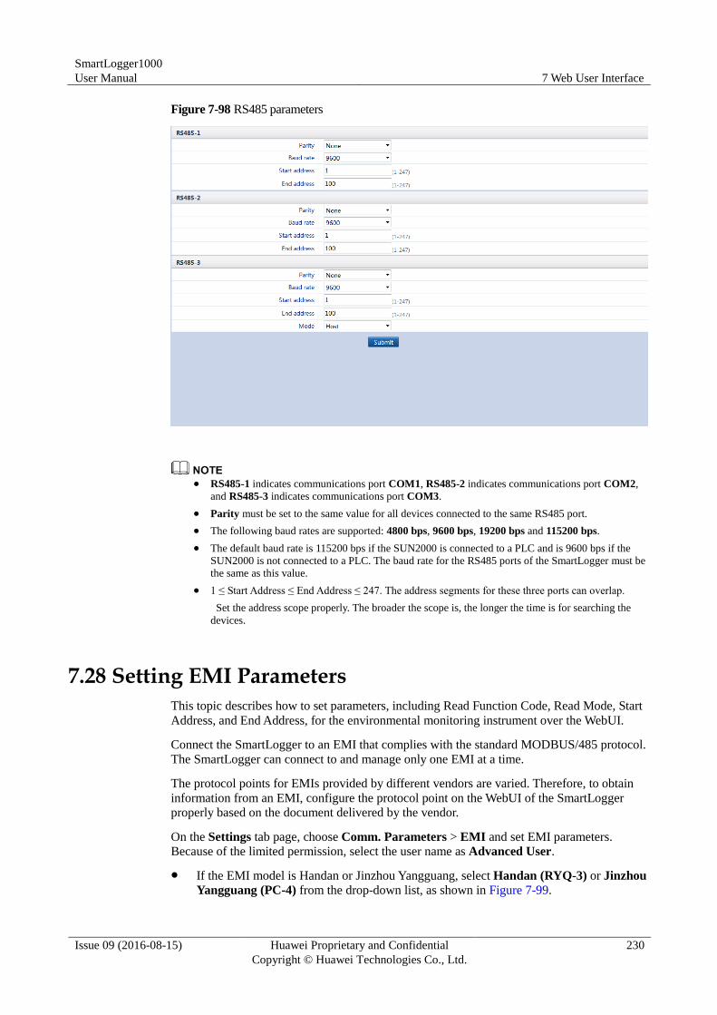
SmartLogger1000
User Manual 7 Web User Interface
Issue 09 (2016-08-15) Huawei Proprietary and Confidential
Copyright © Huawei Technologies Co., Ltd.
230
Figure 7-98 RS485 parameters
RS485-1 indicates communications port COM1, RS485-2 indicates communications port COM2,
and RS485-3 indicates communications port COM3.
Parity must be set to the same value for all devices connected to the same RS485 port.
The following baud rates are supported: 4800 bps, 9600 bps, 19200 bps and 115200 bps.
The default baud rate is 115200 bps if the SUN2000 is connected to a PLC and is 9600 bps if the
SUN2000 is not connected to a PLC. The baud rate for the RS485 ports of the SmartLogger must be
the same as this value.
1 ≤ Start Address ≤ End Address ≤ 247. The address segments for these three ports can overlap.
Set the address scope properly. The broader the scope is, the longer the time is for searching the
devices.
7.28 Setting EMI Parameters
This topic describes how to set parameters, including Read Function Code, Read Mode, Start
Address, and End Address, for the environmental monitoring instrument over the WebUI.
Connect the SmartLogger to an EMI that complies with the standard MODBUS/485 protocol.
The SmartLogger can connect to and manage only one EMI at a time.
The protocol points for EMIs provided by different vendors are varied. Therefore, to obtain
information from an EMI, configure the protocol point on the WebUI of the SmartLogger
properly based on the document delivered by the vendor.
On the Settings tab page, choose Comm. Parameters > EMI and set EMI parameters.
Because of the limited permission, select the user name as Advanced User.
If the EMI model is Handan or Jinzhou Yangguang, select Handan (RYQ-3) or Jinzhou
Yangguang (PC-4) from the drop-down list, as shown in Figure 7-99.
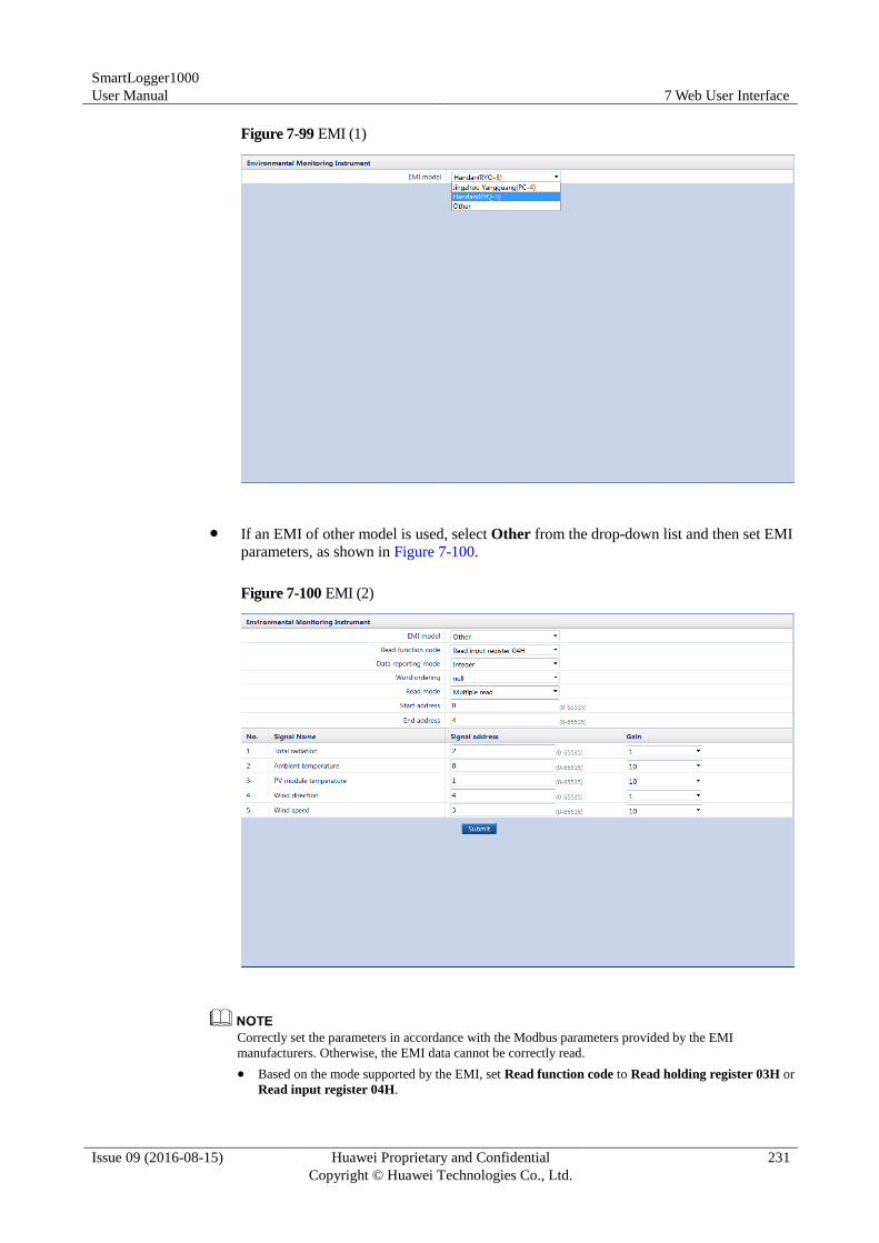
SmartLogger1000
User Manual 7 Web User Interface
Issue 09 (2016-08-15) Huawei Proprietary and Confidential
Copyright © Huawei Technologies Co., Ltd.
231
Figure 7-99 EMI (1)
If an EMI of other model is used, select Other from the drop-down list and then set EMI
parameters, as shown in Figure 7-100.
Figure 7-100 EMI (2)
Correctly set the parameters in accordance with the Modbus parameters provided by the EMI
manufacturers. Otherwise, the EMI data cannot be correctly read.
Based on the mode supported by the EMI, set Read function code to Read holding register 03H or
Read input register 04H.
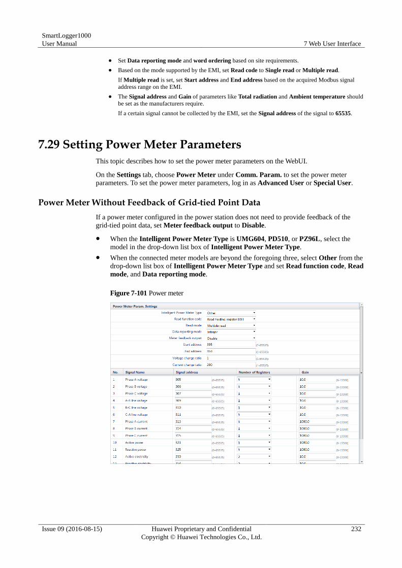
SmartLogger1000
User Manual 7 Web User Interface
Issue 09 (2016-08-15) Huawei Proprietary and Confidential
Copyright © Huawei Technologies Co., Ltd.
232
Set Data reporting mode and word ordering based on site requirements.
Based on the mode supported by the EMI, set Read code to Single read or Multiple read.
If Multiple read is set, set Start address and End address based on the acquired Modbus signal
address range on the EMI.
The Signal address and Gain of parameters like Total radiation and Ambient temperature should
be set as the manufacturers require.
If a certain signal cannot be collected by the EMI, set the Signal address of the signal to 65535.
7.29 Setting Power Meter Parameters
This topic describes how to set the power meter parameters on the WebUI.
On the Settings tab, choose Power Meter under Comm. Param. to set the power meter
parameters. To set the power meter parameters, log in as Advanced User or Special User.
Power Meter Without Feedback of Grid-tied Point Data
If a power meter configured in the power station does not need to provide feedback of the
grid-tied point data, set Meter feedback output to Disable.
When the Intelligent Power Meter Type is UMG604, PD510, or PZ96L, select the
model in the drop-down list box of Intelligent Power Meter Type.
When the connected meter models are beyond the foregoing three, select Other from the
drop-down list box of Intelligent Power Meter Type and set Read function code, Read
mode, and Data reporting mode.
Figure 7-101 Power meter
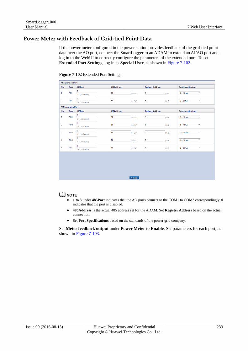
SmartLogger1000
User Manual 7 Web User Interface
Issue 09 (2016-08-15) Huawei Proprietary and Confidential
Copyright © Huawei Technologies Co., Ltd.
233
Power Meter with Feedback of Grid-tied Point Data
If the power meter configured in the power station provides feedback of the grid-tied point
data over the AO port, connect the SmartLogger to an ADAM to extend an AI/AO port and
log in to the WebUI to correctly configure the parameters of the extended port. To set
Extended Port Settings, log in as Special User, as shown in Figure 7-102.
Figure 7-102 Extended Port Settings
1 to 3 under 485Port indicates that the AO ports connect to the COM1 to COM3 correspondingly. 0
indicates that the port is disabled.
485Address is the actual 485 address set for the ADAM. Set Register Address based on the actual
connection.
Set Port Specifications based on the standards of the power grid company.
Set Meter feedback output under Power Meter to Enable. Set parameters for each port, as
shown in Figure 7-103.
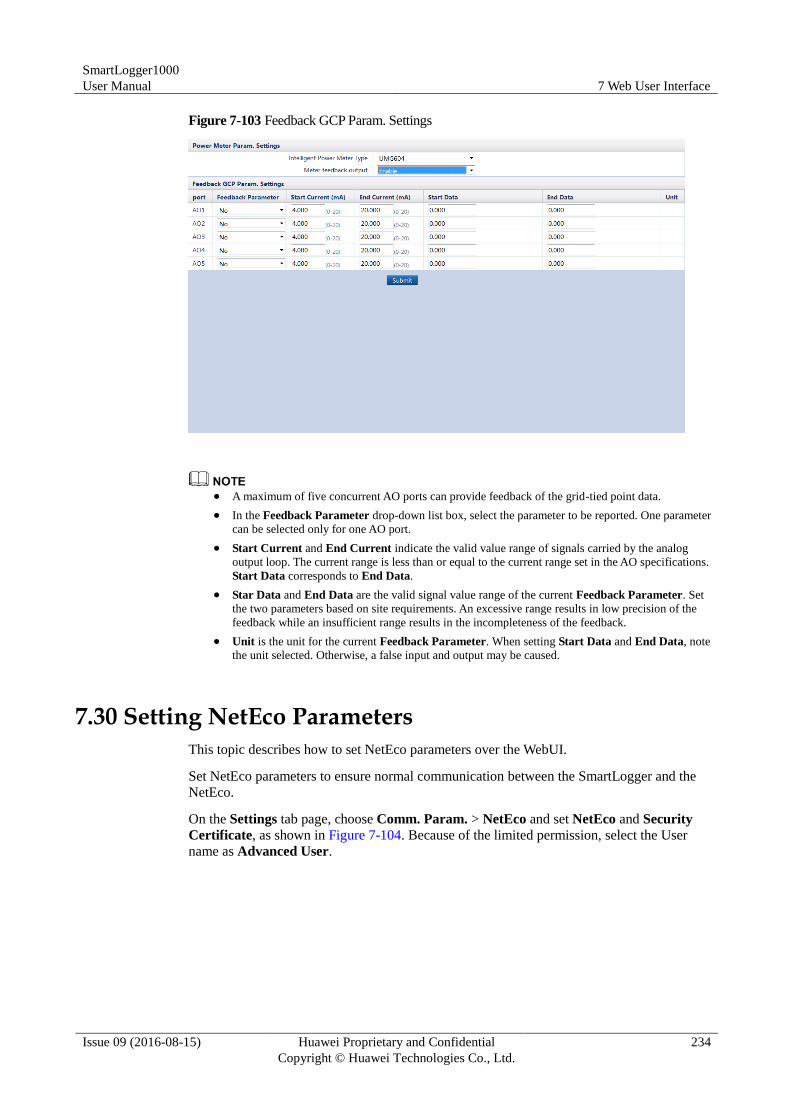
SmartLogger1000
User Manual 7 Web User Interface
Issue 09 (2016-08-15) Huawei Proprietary and Confidential
Copyright © Huawei Technologies Co., Ltd.
234
Figure 7-103 Feedback GCP Param. Settings
A maximum of five concurrent AO ports can provide feedback of the grid-tied point data.
In the Feedback Parameter drop-down list box, select the parameter to be reported. One parameter
can be selected only for one AO port.
Start Current and End Current indicate the valid value range of signals carried by the analog
output loop. The current range is less than or equal to the current range set in the AO specifications.
Start Data corresponds to End Data.
Star Data and End Data are the valid signal value range of the current Feedback Parameter. Set
the two parameters based on site requirements. An excessive range results in low precision of the
feedback while an insufficient range results in the incompleteness of the feedback.
Unit is the unit for the current Feedback Parameter. When setting Start Data and End Data, note
the unit selected. Otherwise, a false input and output may be caused.
7.30 Setting NetEco Parameters
This topic describes how to set NetEco parameters over the WebUI.
Set NetEco parameters to ensure normal communication between the SmartLogger and the
NetEco.
On the Settings tab page, choose Comm. Param. > NetEco and set NetEco and Security
Certificate, as shown in Figure 7-104. Because of the limited permission, select the User
name as Advanced User.
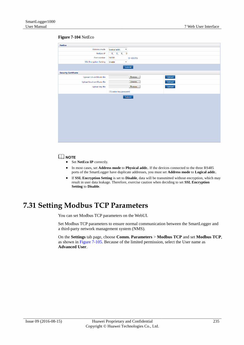
SmartLogger1000
User Manual 7 Web User Interface
Issue 09 (2016-08-15) Huawei Proprietary and Confidential
Copyright © Huawei Technologies Co., Ltd.
235
Figure 7-104 NetEco
Set NetEco IP correctly.
In most cases, set Address mode to Physical addr.. If the devices connected to the three RS485
ports of the SmartLogger have duplicate addresses, you must set Address mode to Logical addr..
If SSL Encryption Setting is set to Disable, data will be transmitted without encryption, which may
result in user data leakage. Therefore, exercise caution when deciding to set SSL Encryption
Setting to Disable.
7.31 Setting Modbus TCP Parameters
You can set Modbus TCP parameters on the WebUI.
Set Modbus TCP parameters to ensure normal communication between the SmartLogger and
a third-party network management system (NMS).
On the Settings tab page, choose Comm. Parameters > Modbus TCP and set Modbus TCP,
as shown in Figure 7-105. Because of the limited permission, select the User name as
Advanced User.
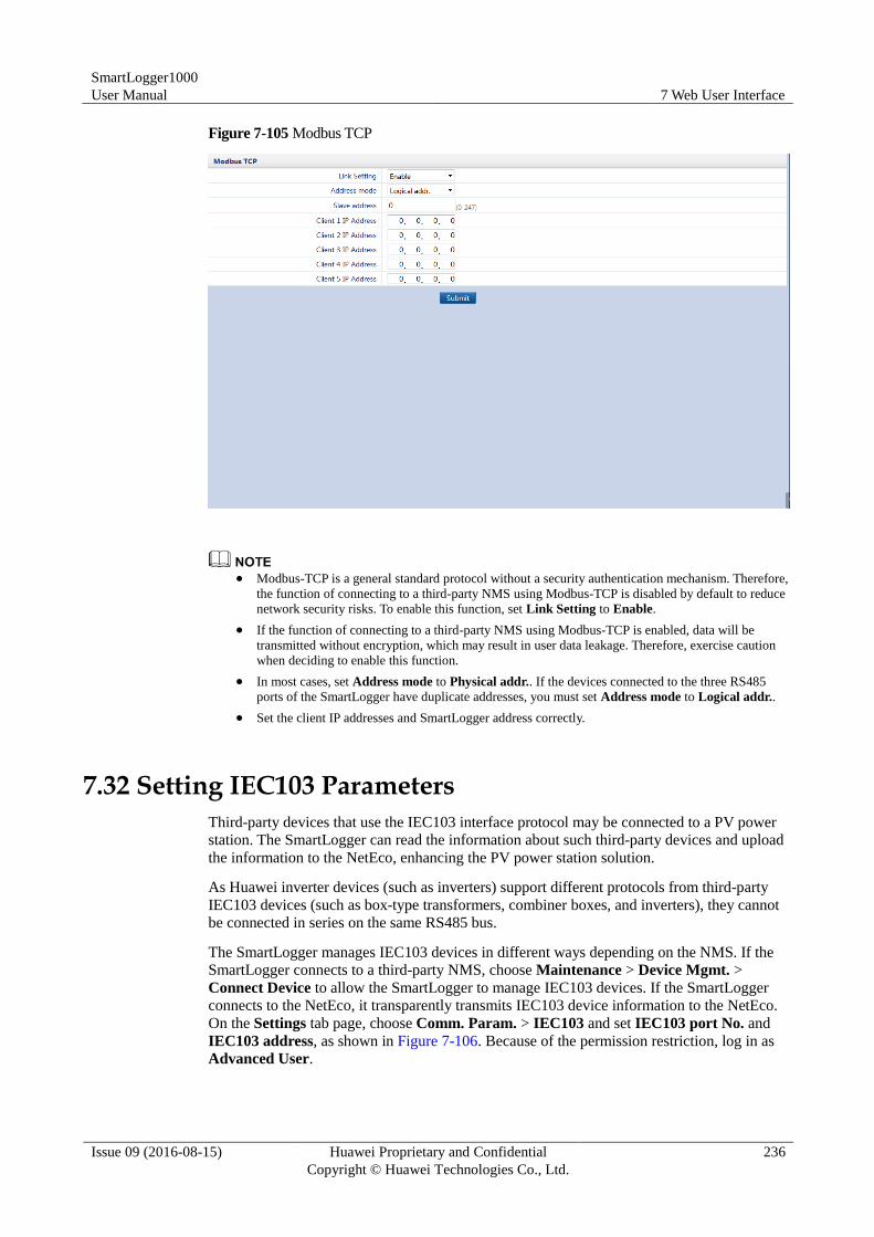
SmartLogger1000
User Manual 7 Web User Interface
Issue 09 (2016-08-15) Huawei Proprietary and Confidential
Copyright © Huawei Technologies Co., Ltd.
236
Figure 7-105 Modbus TCP
Modbus-TCP is a general standard protocol without a security authentication mechanism. Therefore,
the function of connecting to a third-party NMS using Modbus-TCP is disabled by default to reduce
network security risks. To enable this function, set Link Setting to Enable.
If the function of connecting to a third-party NMS using Modbus-TCP is enabled, data will be
transmitted without encryption, which may result in user data leakage. Therefore, exercise caution
when deciding to enable this function.
In most cases, set Address mode to Physical addr.. If the devices connected to the three RS485
ports of the SmartLogger have duplicate addresses, you must set Address mode to Logical addr..
Set the client IP addresses and SmartLogger address correctly.
7.32 Setting IEC103 Parameters
Third-party devices that use the IEC103 interface protocol may be connected to a PV power
station. The SmartLogger can read the information about such third-party devices and upload
the information to the NetEco, enhancing the PV power station solution.
As Huawei inverter devices (such as inverters) support different protocols from third-party
IEC103 devices (such as box-type transformers, combiner boxes, and inverters), they cannot
be connected in series on the same RS485 bus.
The SmartLogger manages IEC103 devices in different ways depending on the NMS. If the
SmartLogger connects to a third-party NMS, choose Maintenance > Device Mgmt. >
Connect Device to allow the SmartLogger to manage IEC103 devices. If the SmartLogger
connects to the NetEco, it transparently transmits IEC103 device information to the NetEco.
On the Settings tab page, choose Comm. Param. > IEC103 and set IEC103 port No. and
IEC103 address, as shown in Figure 7-106. Because of the permission restriction, log in as
Advanced User.
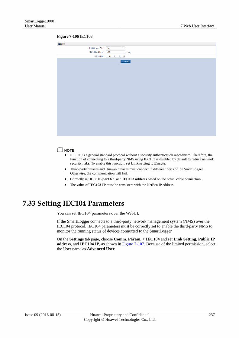
SmartLogger1000
User Manual 7 Web User Interface
Issue 09 (2016-08-15) Huawei Proprietary and Confidential
Copyright © Huawei Technologies Co., Ltd.
237
Figure 7-106 IEC103
IEC103 is a general standard protocol without a security authentication mechanism. Therefore, the
function of connecting to a third-party NMS using IEC103 is disabled by default to reduce network
security risks. To enable this function, set Link setting to Enable.
Third-party devices and Huawei devices must connect to different ports of the SmartLogger.
Otherwise, the communication will fail.
Correctly set IEC103 port No. and IEC103 address based on the actual cable connection.
The value of IEC103 IP must be consistent with the NetEco IP address.
7.33 Setting IEC104 Parameters
You can set IEC104 parameters over the WebUI.
If the SmartLogger connects to a third-party network management system (NMS) over the
IEC104 protocol, IEC104 parameters must be correctly set to enable the third-party NMS to
monitor the running status of devices connected to the SmartLogger.
On the Settings tab page, choose Comm. Param. > IEC104 and set Link Setting, Public IP
address, and IEC104 IP, as shown in Figure 7-107. Because of the limited permission, select
the User name as Advanced User.
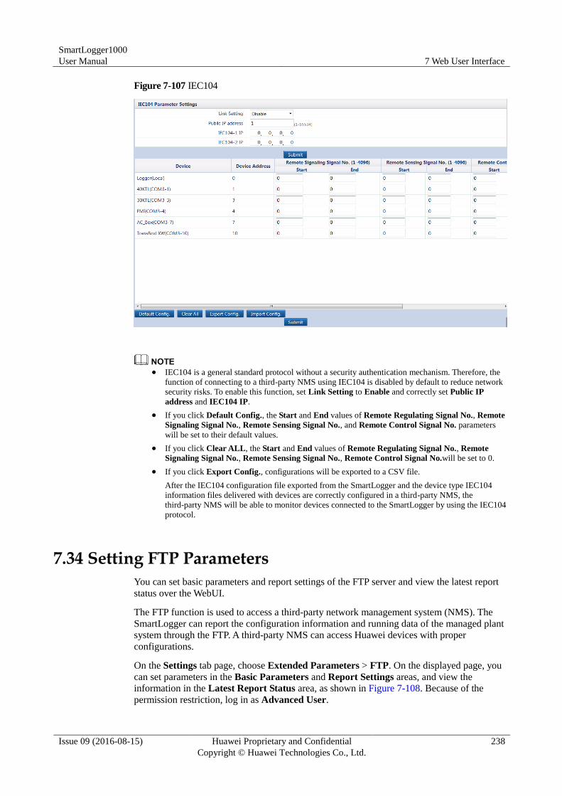
SmartLogger1000
User Manual 7 Web User Interface
Issue 09 (2016-08-15) Huawei Proprietary and Confidential
Copyright © Huawei Technologies Co., Ltd.
238
Figure 7-107 IEC104
IEC104 is a general standard protocol without a security authentication mechanism. Therefore, the
function of connecting to a third-party NMS using IEC104 is disabled by default to reduce network
security risks. To enable this function, set Link Setting to Enable and correctly set Public IP
address and IEC104 IP.
If you click Default Config., the Start and End values of Remote Regulating Signal No., Remote
Signaling Signal No., Remote Sensing Signal No., and Remote Control Signal No. parameters
will be set to their default values.
If you click Clear ALL, the Start and End values of Remote Regulating Signal No., Remote
Signaling Signal No., Remote Sensing Signal No., Remote Control Signal No.will be set to 0.
If you click Export Config., configurations will be exported to a CSV file.
After the IEC104 configuration file exported from the SmartLogger and the device type IEC104
information files delivered with devices are correctly configured in a third-party NMS, the
third-party NMS will be able to monitor devices connected to the SmartLogger by using the IEC104
protocol.
7.34 Setting FTP Parameters
You can set basic parameters and report settings of the FTP server and view the latest report
status over the WebUI.
The FTP function is used to access a third-party network management system (NMS). The
SmartLogger can report the configuration information and running data of the managed plant
system through the FTP. A third-party NMS can access Huawei devices with proper
configurations.
On the Settings tab page, choose Extended Parameters > FTP. On the displayed page, you
can set parameters in the Basic Parameters and Report Settings areas, and view the
information in the Latest Report Status area, as shown in Figure 7-108. Because of the
permission restriction, log in as Advanced User.
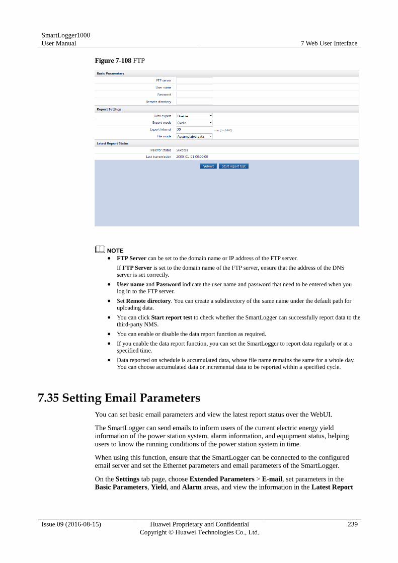
SmartLogger1000
User Manual 7 Web User Interface
Issue 09 (2016-08-15) Huawei Proprietary and Confidential
Copyright © Huawei Technologies Co., Ltd.
239
Figure 7-108 FTP
FTP Server can be set to the domain name or IP address of the FTP server.
If FTP Server is set to the domain name of the FTP server, ensure that the address of the DNS
server is set correctly.
User name and Password indicate the user name and password that need to be entered when you
log in to the FTP server.
Set Remote directory. You can create a subdirectory of the same name under the default path for
uploading data.
You can click Start report test to check whether the SmartLogger can successfully report data to the
third-party NMS.
You can enable or disable the data report function as required.
If you enable the data report function, you can set the SmartLogger to report data regularly or at a
specified time.
Data reported on schedule is accumulated data, whose file name remains the same for a whole day.
You can choose accumulated data or incremental data to be reported within a specified cycle.
7.35 Setting Email Parameters
You can set basic email parameters and view the latest report status over the WebUI.
The SmartLogger can send emails to inform users of the current electric energy yield
information of the power station system, alarm information, and equipment status, helping
users to know the running conditions of the power station system in time.
When using this function, ensure that the SmartLogger can be connected to the configured
email server and set the Ethernet parameters and email parameters of the SmartLogger.
On the Settings tab page, choose Extended Parameters > E-mail, set parameters in the
Basic Parameters, Yield, and Alarm areas, and view the information in the Latest Report
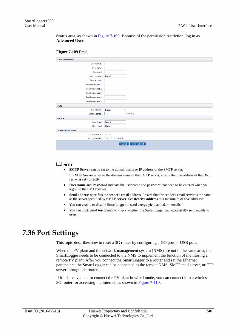
SmartLogger1000
User Manual 7 Web User Interface
Issue 09 (2016-08-15) Huawei Proprietary and Confidential
Copyright © Huawei Technologies Co., Ltd.
240
Status area, as shown in Figure 7-109. Because of the permission restriction, log in as
Advanced User.
Figure 7-109 Email
SMTP Server can be set to the domain name or IP address of the SMTP server.
If SMTP Server is set to the domain name of the SMTP server, ensure that the address of the DNS
server is set correctly.
User name and Password indicate the user name and password that need to be entered when you
log in to the SMTP server.
Send address specifies the sender's email address. Ensure that the sender's email server is the same
as the server specified by SMTP server. Set Receive address to a maximum of five addresses.
You can enable or disable SmartLogger to send energy yield and alarm emails.
You can click Send test Email to check whether the SmartLogger can successfully send emails to
users.
7.36 Port Settings
This topic describes how to reset a 3G router by configuring a DO port or USB port.
When the PV plant and the network management system (NMS) are not in the same area, the
SmartLogger needs to be connected to the NMS to implement the function of monitoring a
remote PV plant. After you connect the SmartLogger to a router and set the Ethernet
parameters, the SmartLogger can be connected to the remote NMS, SMTP mail server, or FTP
server through the router.
If it is inconvenient to connect the PV plant in wired mode, you can connect it to a wireless
3G router for accessing the Internet, as shown in Figure 7-110.
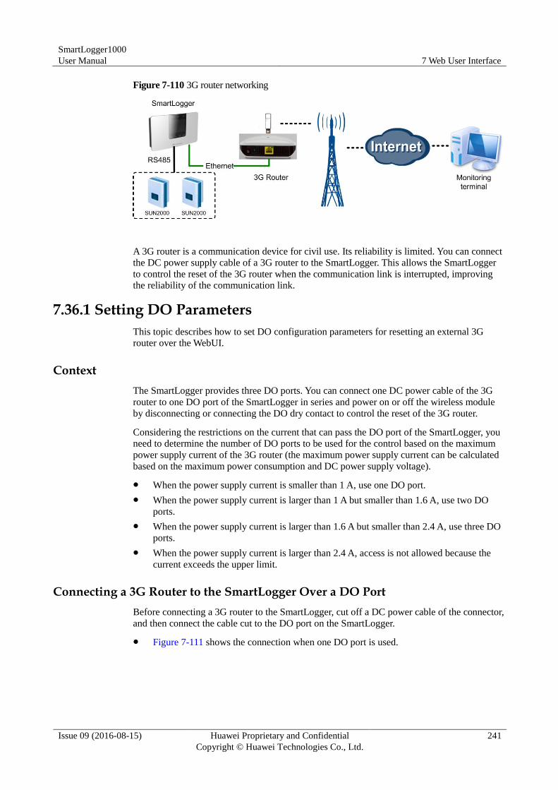
SmartLogger1000
User Manual 7 Web User Interface
Issue 09 (2016-08-15) Huawei Proprietary and Confidential
Copyright © Huawei Technologies Co., Ltd.
241
Figure 7-110 3G router networking
A 3G router is a communication device for civil use. Its reliability is limited. You can connect
the DC power supply cable of a 3G router to the SmartLogger. This allows the SmartLogger
to control the reset of the 3G router when the communication link is interrupted, improving
the reliability of the communication link.
7.36.1 Setting DO Parameters
This topic describes how to set DO configuration parameters for resetting an external 3G
router over the WebUI.
Context
The SmartLogger provides three DO ports. You can connect one DC power cable of the 3G
router to one DO port of the SmartLogger in series and power on or off the wireless module
by disconnecting or connecting the DO dry contact to control the reset of the 3G router.
Considering the restrictions on the current that can pass the DO port of the SmartLogger, you
need to determine the number of DO ports to be used for the control based on the maximum
power supply current of the 3G router (the maximum power supply current can be calculated
based on the maximum power consumption and DC power supply voltage).
When the power supply current is smaller than 1 A, use one DO port.
When the power supply current is larger than 1 A but smaller than 1.6 A, use two DO
ports.
When the power supply current is larger than 1.6 A but smaller than 2.4 A, use three DO
ports.
When the power supply current is larger than 2.4 A, access is not allowed because the
current exceeds the upper limit.
Connecting a 3G Router to the SmartLogger Over a DO Port
Before connecting a 3G router to the SmartLogger, cut off a DC power cable of the connector,
and then connect the cable cut to the DO port on the SmartLogger.
Figure 7-111 shows the connection when one DO port is used.
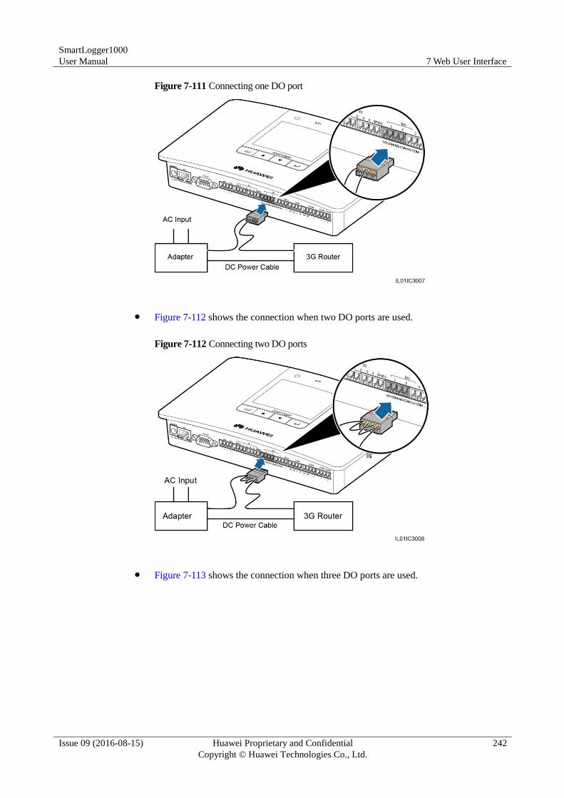
SmartLogger1000
User Manual 7 Web User Interface
Issue 09 (2016-08-15) Huawei Proprietary and Confidential
Copyright © Huawei Technologies Co., Ltd.
242
Figure 7-111 Connecting one DO port
Figure 7-112 shows the connection when two DO ports are used.
Figure 7-112 Connecting two DO ports
Figure 7-113 shows the connection when three DO ports are used.
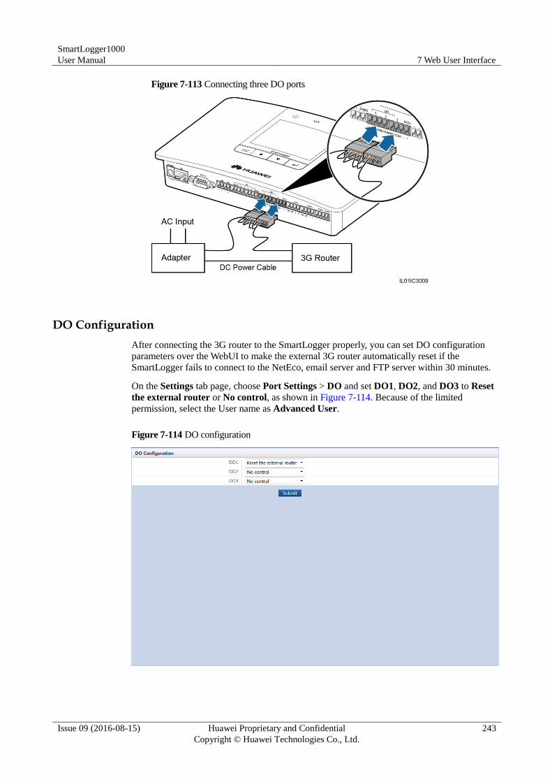
SmartLogger1000
User Manual 7 Web User Interface
Issue 09 (2016-08-15) Huawei Proprietary and Confidential
Copyright © Huawei Technologies Co., Ltd.
243
Figure 7-113 Connecting three DO ports
DO Configuration
After connecting the 3G router to the SmartLogger properly, you can set DO configuration
parameters over the WebUI to make the external 3G router automatically reset if the
SmartLogger fails to connect to the NetEco, email server and FTP server within 30 minutes.
On the Settings tab page, choose Port Settings > DO and set DO1, DO2, and DO3 to Reset
the external router or No control, as shown in Figure 7-114. Because of the limited
permission, select the User name as Advanced User.
Figure 7-114 DO configuration
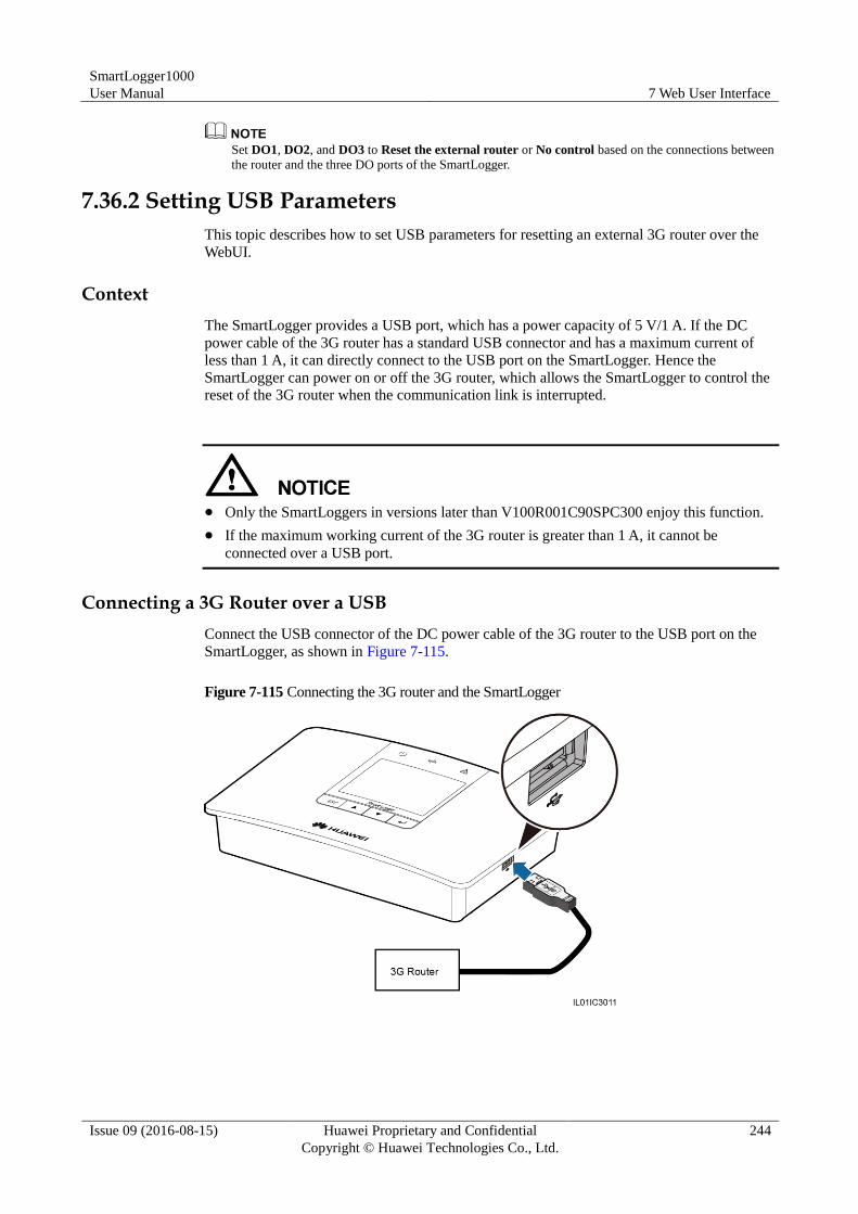
SmartLogger1000
User Manual 7 Web User Interface
Issue 09 (2016-08-15) Huawei Proprietary and Confidential
Copyright © Huawei Technologies Co., Ltd.
244
Set DO1, DO2, and DO3 to Reset the external router or No control based on the connections between
the router and the three DO ports of the SmartLogger.
7.36.2 Setting USB Parameters
This topic describes how to set USB parameters for resetting an external 3G router over the
WebUI.
Context
The SmartLogger provides a USB port, which has a power capacity of 5 V/1 A. If the DC
power cable of the 3G router has a standard USB connector and has a maximum current of
less than 1 A, it can directly connect to the USB port on the SmartLogger. Hence the
SmartLogger can power on or off the 3G router, which allows the SmartLogger to control the
reset of the 3G router when the communication link is interrupted.
Only the SmartLoggers in versions later than V100R001C90SPC300 enjoy this function.
If the maximum working current of the 3G router is greater than 1 A, it cannot be
connected over a USB port.
Connecting a 3G Router over a USB
Connect the USB connector of the DC power cable of the 3G router to the USB port on the
SmartLogger, as shown in Figure 7-115.
Figure 7-115 Connecting the 3G router and the SmartLogger
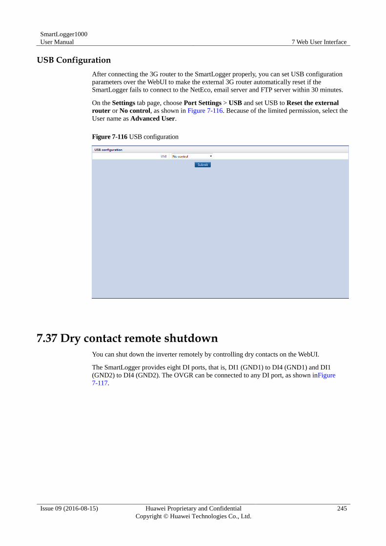
SmartLogger1000
User Manual 7 Web User Interface
Issue 09 (2016-08-15) Huawei Proprietary and Confidential
Copyright © Huawei Technologies Co., Ltd.
245
USB Configuration
After connecting the 3G router to the SmartLogger properly, you can set USB configuration
parameters over the WebUI to make the external 3G router automatically reset if the
SmartLogger fails to connect to the NetEco, email server and FTP server within 30 minutes.
On the Settings tab page, choose Port Settings > USB and set USB to Reset the external
router or No control, as shown in Figure 7-116. Because of the limited permission, select the
User name as Advanced User.
Figure 7-116 USB configuration
7.37 Dry contact remote shutdown
You can shut down the inverter remotely by controlling dry contacts on the WebUI.
The SmartLogger provides eight DI ports, that is, DI1 (GND1) to DI4 (GND1) and DI1
(GND2) to DI4 (GND2). The OVGR can be connected to any DI port, as shown inFigure
7-117.
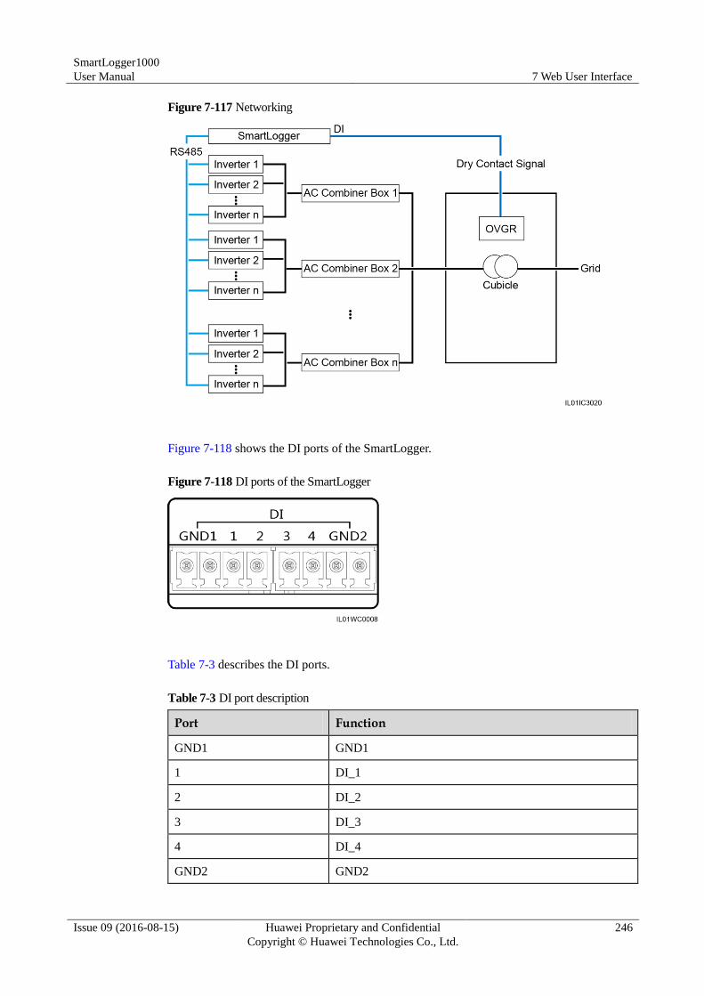
SmartLogger1000
User Manual 7 Web User Interface
Issue 09 (2016-08-15) Huawei Proprietary and Confidential
Copyright © Huawei Technologies Co., Ltd.
246
Figure 7-117 Networking
Figure 7-118 shows the DI ports of the SmartLogger.
Figure 7-118 DI ports of the SmartLogger
Table 7-3 describes the DI ports.
Table 7-3 DI port description
Port Function
GND1 GND1
1 DI_1
2 DI_2
3 DI_3
4 DI_4
GND2 GND2
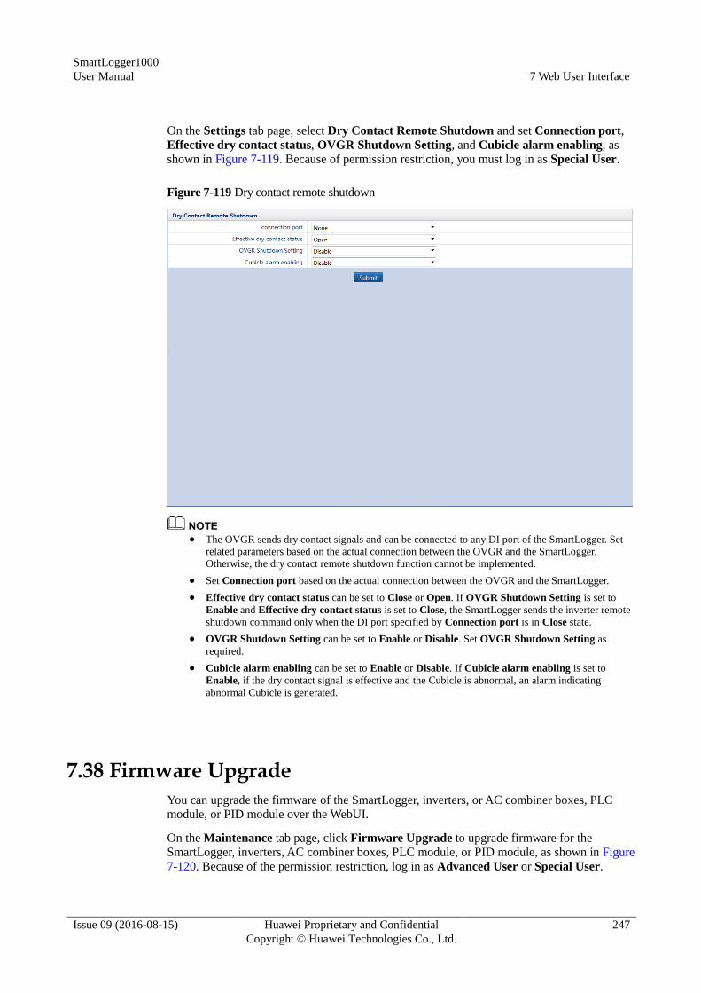
SmartLogger1000
User Manual 7 Web User Interface
Issue 09 (2016-08-15) Huawei Proprietary and Confidential
Copyright © Huawei Technologies Co., Ltd.
247
On the Settings tab page, select Dry Contact Remote Shutdown and set Connection port,
Effective dry contact status, OVGR Shutdown Setting, and Cubicle alarm enabling, as
shown in Figure 7-119. Because of permission restriction, you must log in as Special User.
Figure 7-119 Dry contact remote shutdown
The OVGR sends dry contact signals and can be connected to any DI port of the SmartLogger. Set
related parameters based on the actual connection between the OVGR and the SmartLogger.
Otherwise, the dry contact remote shutdown function cannot be implemented.
Set Connection port based on the actual connection between the OVGR and the SmartLogger.
Effective dry contact status can be set to Close or Open. If OVGR Shutdown Setting is set to
Enable and Effective dry contact status is set to Close, the SmartLogger sends the inverter remote
shutdown command only when the DI port specified by Connection port is in Close state.
OVGR Shutdown Setting can be set to Enable or Disable. Set OVGR Shutdown Setting as
required.
Cubicle alarm enabling can be set to Enable or Disable. If Cubicle alarm enabling is set to
Enable, if the dry contact signal is effective and the Cubicle is abnormal, an alarm indicating
abnormal Cubicle is generated.
7.38 Firmware Upgrade
You can upgrade the firmware of the SmartLogger, inverters, or AC combiner boxes, PLC
module, or PID module over the WebUI.
On the Maintenance tab page, click Firmware Upgrade to upgrade firmware for the
SmartLogger, inverters, AC combiner boxes, PLC module, or PID module, as shown in Figure
7-120. Because of the permission restriction, log in as Advanced User or Special User.
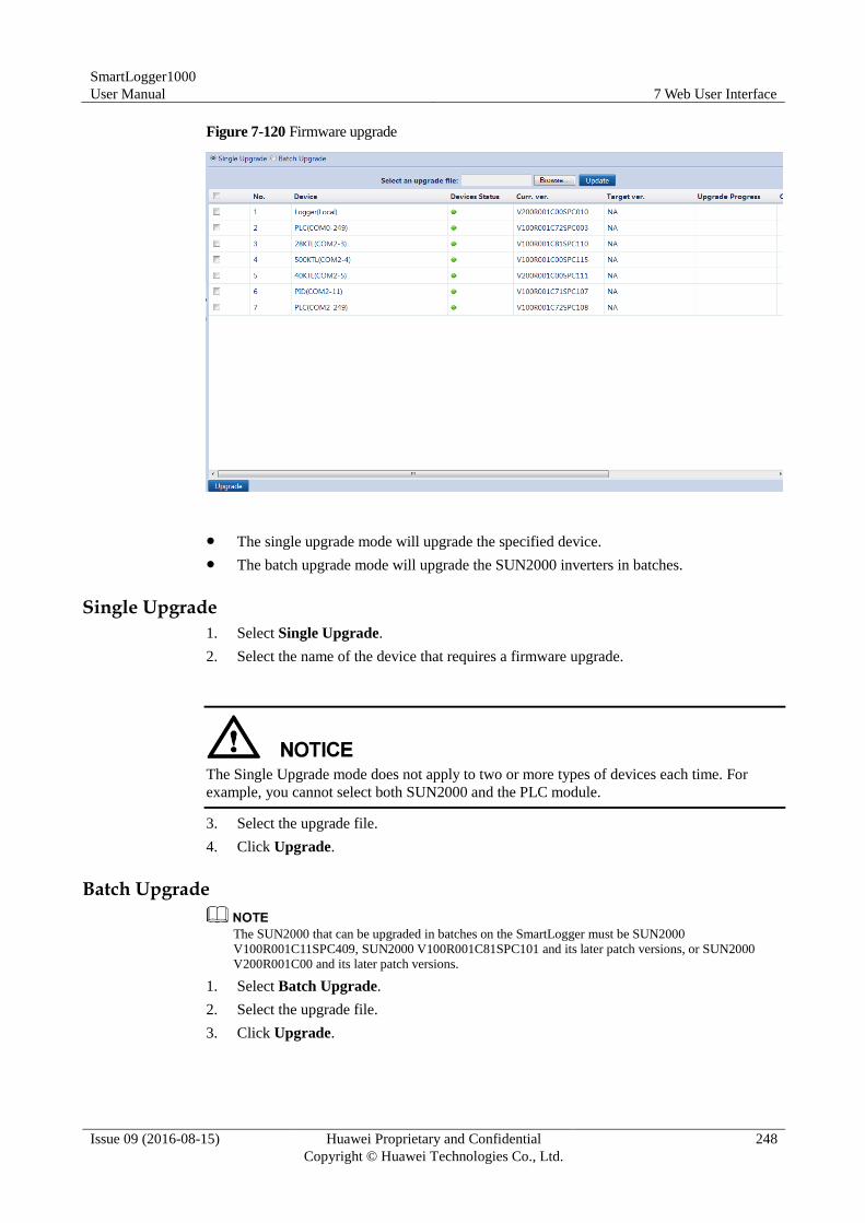
SmartLogger1000
User Manual 7 Web User Interface
Issue 09 (2016-08-15) Huawei Proprietary and Confidential
Copyright © Huawei Technologies Co., Ltd.
248
Figure 7-120 Firmware upgrade
The single upgrade mode will upgrade the specified device.
The batch upgrade mode will upgrade the SUN2000 inverters in batches.
Single Upgrade
1. Select Single Upgrade.
2. Select the name of the device that requires a firmware upgrade.
The Single Upgrade mode does not apply to two or more types of devices each time. For
example, you cannot select both SUN2000 and the PLC module.
3. Select the upgrade file.
4. Click Upgrade.
Batch Upgrade
The SUN2000 that can be upgraded in batches on the SmartLogger must be SUN2000
V100R001C11SPC409, SUN2000 V100R001C81SPC101 and its later patch versions, or SUN2000
V200R001C00 and its later patch versions.
1. Select Batch Upgrade.
2. Select the upgrade file.
3. Click Upgrade.
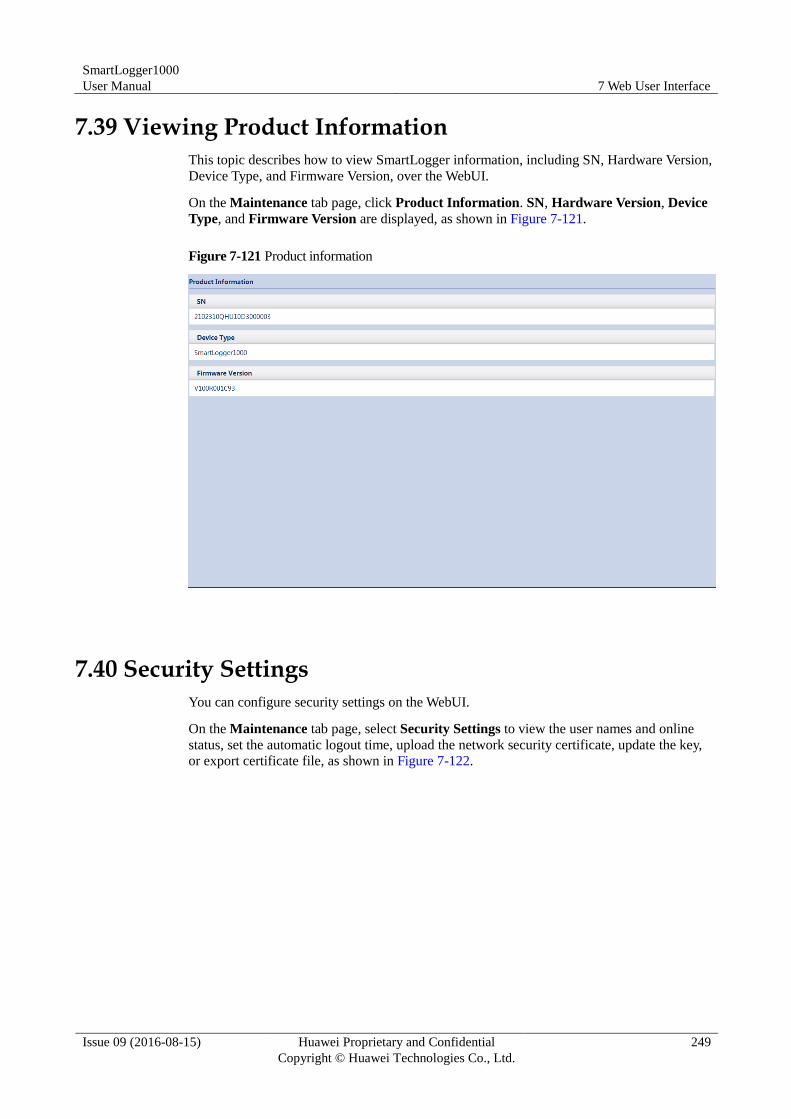
SmartLogger1000
User Manual 7 Web User Interface
Issue 09 (2016-08-15) Huawei Proprietary and Confidential
Copyright © Huawei Technologies Co., Ltd.
249
7.39 Viewing Product Information
This topic describes how to view SmartLogger information, including SN, Hardware Version,
Device Type, and Firmware Version, over the WebUI.
On the Maintenance tab page, click Product Information. SN, Hardware Version, Device
Type, and Firmware Version are displayed, as shown in Figure 7-121.
Figure 7-121 Product information
7.40 Security Settings
You can configure security settings on the WebUI.
On the Maintenance tab page, select Security Settings to view the user names and online
status, set the automatic logout time, upload the network security certificate, update the key,
or export certificate file, as shown in Figure 7-122.
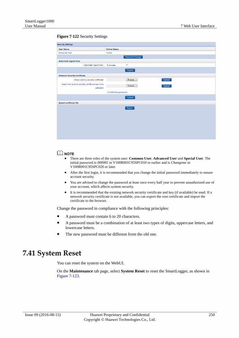
SmartLogger1000
User Manual 7 Web User Interface
Issue 09 (2016-08-15) Huawei Proprietary and Confidential
Copyright © Huawei Technologies Co., Ltd.
250
Figure 7-122 Security Settings
There are three roles of the system user: Common User, Advanced User and Special User. The
initial password is 000001 in V100R001C95SPC010 or earlier and is Changeme in
V100R001C95SPC020 or later.
After the first login, it is recommended that you change the initial password immediately to ensure
account security.
You are advised to change the password at least once every half year to prevent unauthorized use of
your account, which affects system security.
It is recommended that the existing network security certificate and key (if available) be used. If a
network security certificate is not available, you can export the root certificate and import the
certificate to the browser.
Change the password in compliance with the following principles:
A password must contain 6 to 20 characters.
A password must be a combination of at least two types of digits, uppercase letters, and
lowercase letters.
The new password must be different from the old one.
7.41 System Reset
You can reset the system on the WebUI.
On the Maintenance tab page, select System Reset to reset the SmartLogger, as shown in
Figure 7-123.
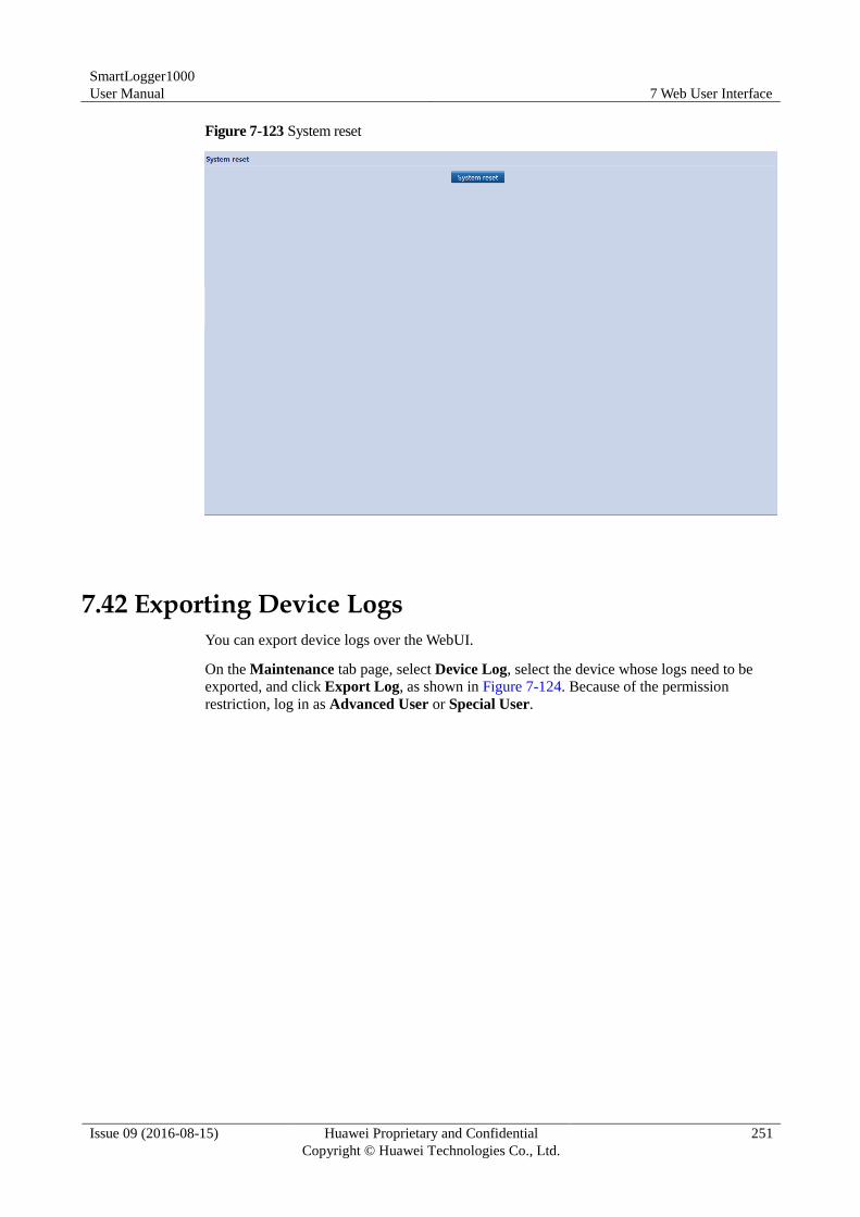
SmartLogger1000
User Manual 7 Web User Interface
Issue 09 (2016-08-15) Huawei Proprietary and Confidential
Copyright © Huawei Technologies Co., Ltd.
251
Figure 7-123 System reset
7.42 Exporting Device Logs
You can export device logs over the WebUI.
On the Maintenance tab page, select Device Log, select the device whose logs need to be
exported, and click Export Log, as shown in Figure 7-124. Because of the permission
restriction, log in as Advanced User or Special User.
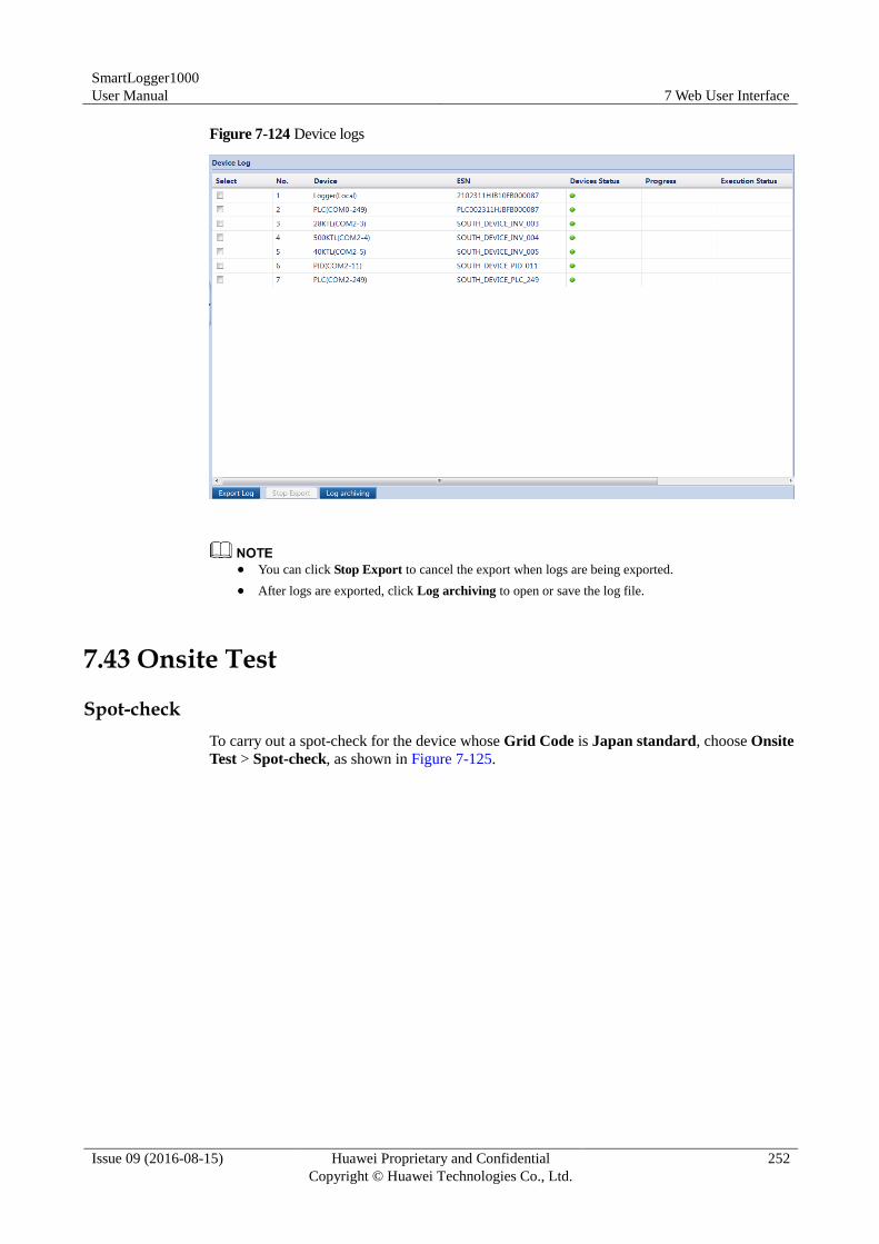
SmartLogger1000
User Manual 7 Web User Interface
Issue 09 (2016-08-15) Huawei Proprietary and Confidential
Copyright © Huawei Technologies Co., Ltd.
252
Figure 7-124 Device logs
You can click Stop Export to cancel the export when logs are being exported.
After logs are exported, click Log archiving to open or save the log file.
7.43 Onsite Test
Spot-check
To carry out a spot-check for the device whose Grid Code is Japan standard, choose Onsite
Test > Spot-check, as shown in Figure 7-125.
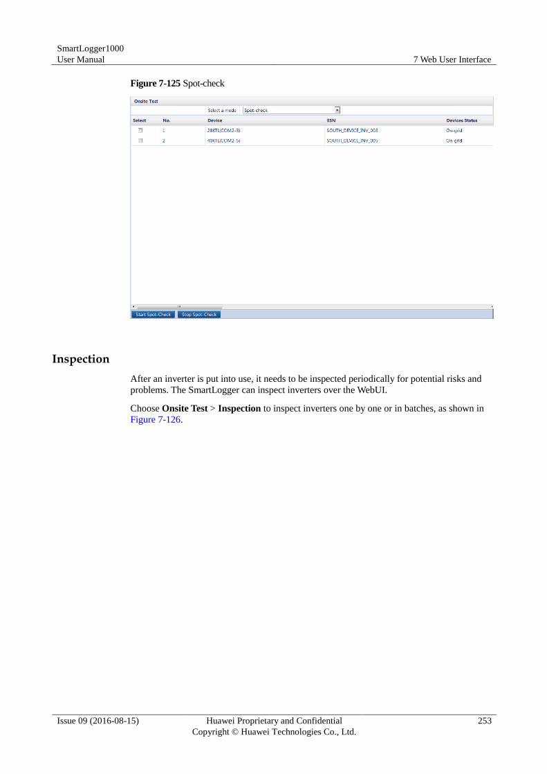
SmartLogger1000
User Manual 7 Web User Interface
Issue 09 (2016-08-15) Huawei Proprietary and Confidential
Copyright © Huawei Technologies Co., Ltd.
253
Figure 7-125 Spot-check
Inspection
After an inverter is put into use, it needs to be inspected periodically for potential risks and
problems. The SmartLogger can inspect inverters over the WebUI.
Choose Onsite Test > Inspection to inspect inverters one by one or in batches, as shown in
Figure 7-126.
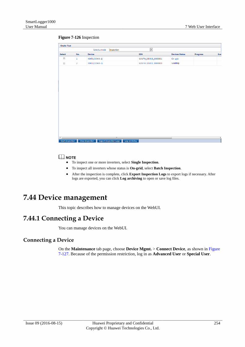
SmartLogger1000
User Manual 7 Web User Interface
Issue 09 (2016-08-15) Huawei Proprietary and Confidential
Copyright © Huawei Technologies Co., Ltd.
254
Figure 7-126 Inspection
To inspect one or more inverters, select Single Inspection.
To inspect all inverters whose status is On-grid, select Batch Inspection.
After the inspection is complete, click Export Inspection Logs to export logs if necessary. After
logs are exported, you can click Log archiving to open or save log files.
7.44 Device management
This topic describes how to manage devices on the WebUI.
7.44.1 Connecting a Device
You can manage devices on the WebUI.
Connecting a Device
On the Maintenance tab page, choose Device Mgmt. > Connect Device, as shown in Figure
7-127. Because of the permission restriction, log in as Advanced User or Special User.
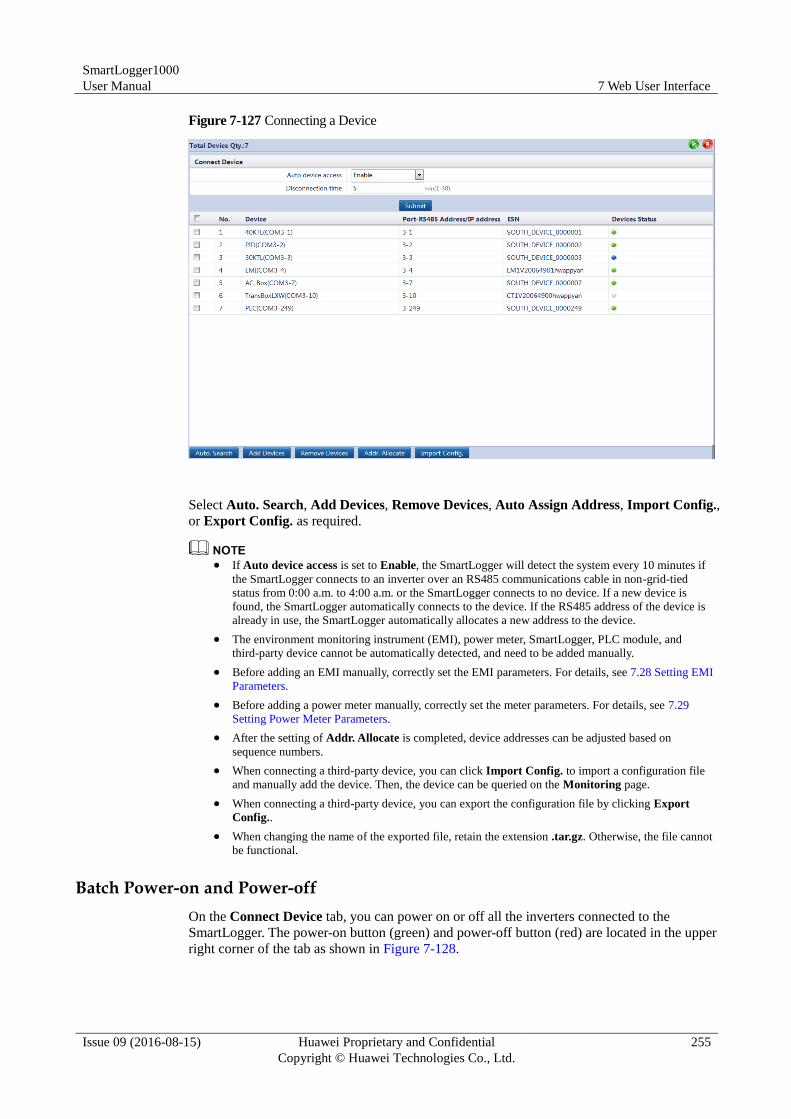
SmartLogger1000
User Manual 7 Web User Interface
Issue 09 (2016-08-15) Huawei Proprietary and Confidential
Copyright © Huawei Technologies Co., Ltd.
255
Figure 7-127 Connecting a Device
Select Auto. Search, Add Devices, Remove Devices, Auto Assign Address, Import Config.,
or Export Config. as required.
If Auto device access is set to Enable, the SmartLogger will detect the system every 10 minutes if
the SmartLogger connects to an inverter over an RS485 communications cable in non-grid-tied
status from 0:00 a.m. to 4:00 a.m. or the SmartLogger connects to no device. If a new device is
found, the SmartLogger automatically connects to the device. If the RS485 address of the device is
already in use, the SmartLogger automatically allocates a new address to the device.
The environment monitoring instrument (EMI), power meter, SmartLogger, PLC module, and
third-party device cannot be automatically detected, and need to be added manually.
Before adding an EMI manually, correctly set the EMI parameters. For details, see 7.28 Setting EMI
Parameters.
Before adding a power meter manually, correctly set the meter parameters. For details, see 7.29
Setting Power Meter Parameters.
After the setting of Addr. Allocate is completed, device addresses can be adjusted based on
sequence numbers.
When connecting a third-party device, you can click Import Config. to import a configuration file
and manually add the device. Then, the device can be queried on the Monitoring page.
When connecting a third-party device, you can export the configuration file by clicking Export
Config..
When changing the name of the exported file, retain the extension .tar.gz. Otherwise, the file cannot
be functional.
Batch Power-on and Power-off
On the Connect Device tab, you can power on or off all the inverters connected to the
SmartLogger. The power-on button (green) and power-off button (red) are located in the upper
right corner of the tab as shown in Figure 7-128.
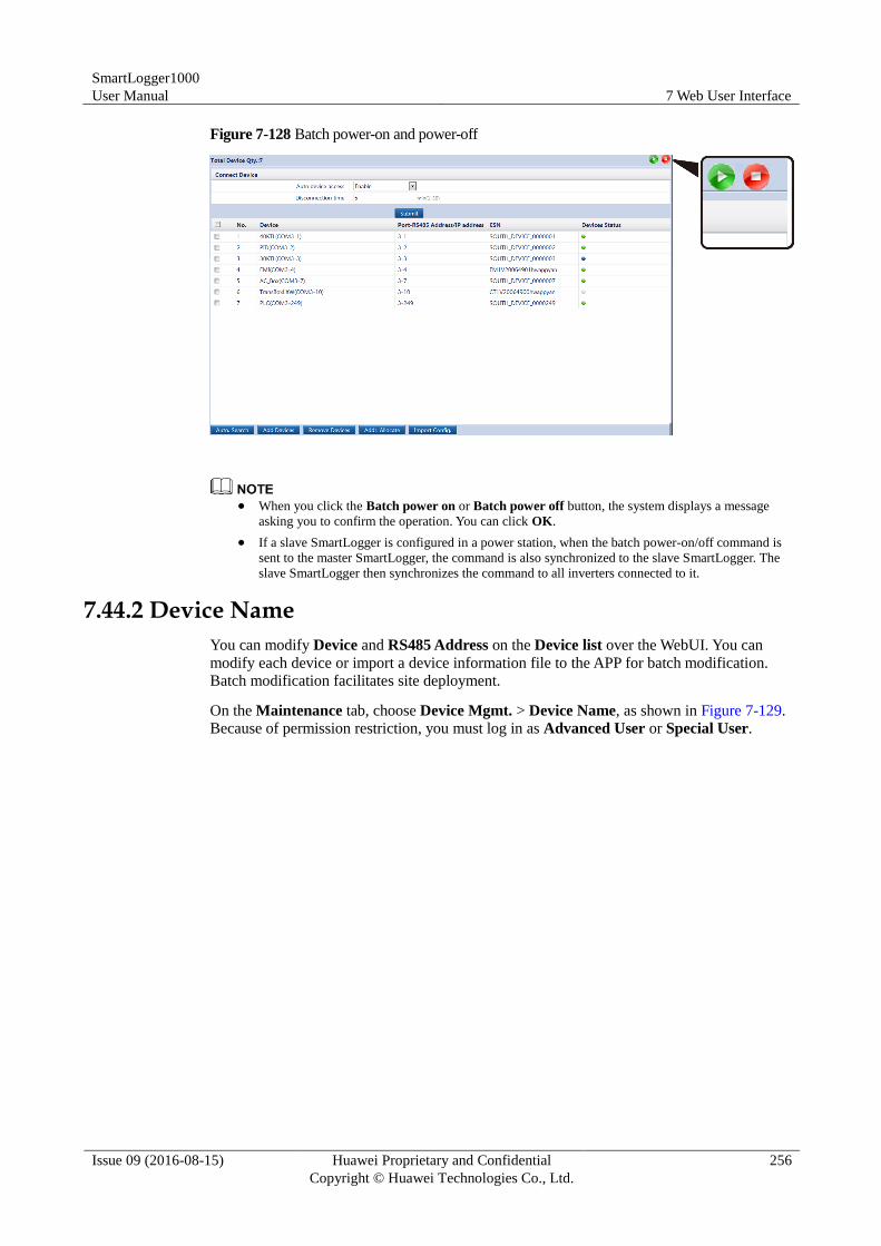
SmartLogger1000
User Manual 7 Web User Interface
Issue 09 (2016-08-15) Huawei Proprietary and Confidential
Copyright © Huawei Technologies Co., Ltd.
256
Figure 7-128 Batch power-on and power-off
When you click the Batch power on or Batch power off button, the system displays a message
asking you to confirm the operation. You can click OK.
If a slave SmartLogger is configured in a power station, when the batch power-on/off command is
sent to the master SmartLogger, the command is also synchronized to the slave SmartLogger. The
slave SmartLogger then synchronizes the command to all inverters connected to it.
7.44.2 Device Name
You can modify Device and RS485 Address on the Device list over the WebUI. You can
modify each device or import a device information file to the APP for batch modification.
Batch modification facilitates site deployment.
On the Maintenance tab, choose Device Mgmt. > Device Name, as shown in Figure 7-129.
Because of permission restriction, you must log in as Advanced User or Special User.
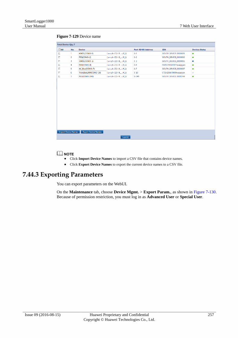
SmartLogger1000
User Manual 7 Web User Interface
Issue 09 (2016-08-15) Huawei Proprietary and Confidential
Copyright © Huawei Technologies Co., Ltd.
257
Figure 7-129 Device name
Click Import Device Names to import a CSV file that contains device names.
Click Export Device Names to export the current device names to a CSV file.
7.44.3 Exporting Parameters
You can export parameters on the WebUI.
On the Maintenance tab, choose Device Mgmt. > Export Param., as shown in Figure 7-130.
Because of permission restriction, you must log in as Advanced User or Special User.
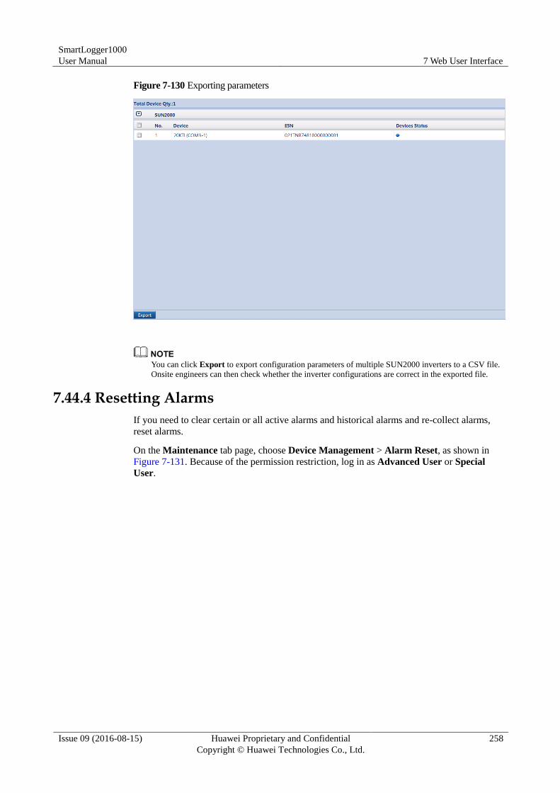
SmartLogger1000
User Manual 7 Web User Interface
Issue 09 (2016-08-15) Huawei Proprietary and Confidential
Copyright © Huawei Technologies Co., Ltd.
258
Figure 7-130 Exporting parameters
You can click Export to export configuration parameters of multiple SUN2000 inverters to a CSV file.
Onsite engineers can then check whether the inverter configurations are correct in the exported file.
7.44.4 Resetting Alarms
If you need to clear certain or all active alarms and historical alarms and re-collect alarms,
reset alarms.
On the Maintenance tab page, choose Device Management > Alarm Reset, as shown in
Figure 7-131. Because of the permission restriction, log in as Advanced User or Special
User.
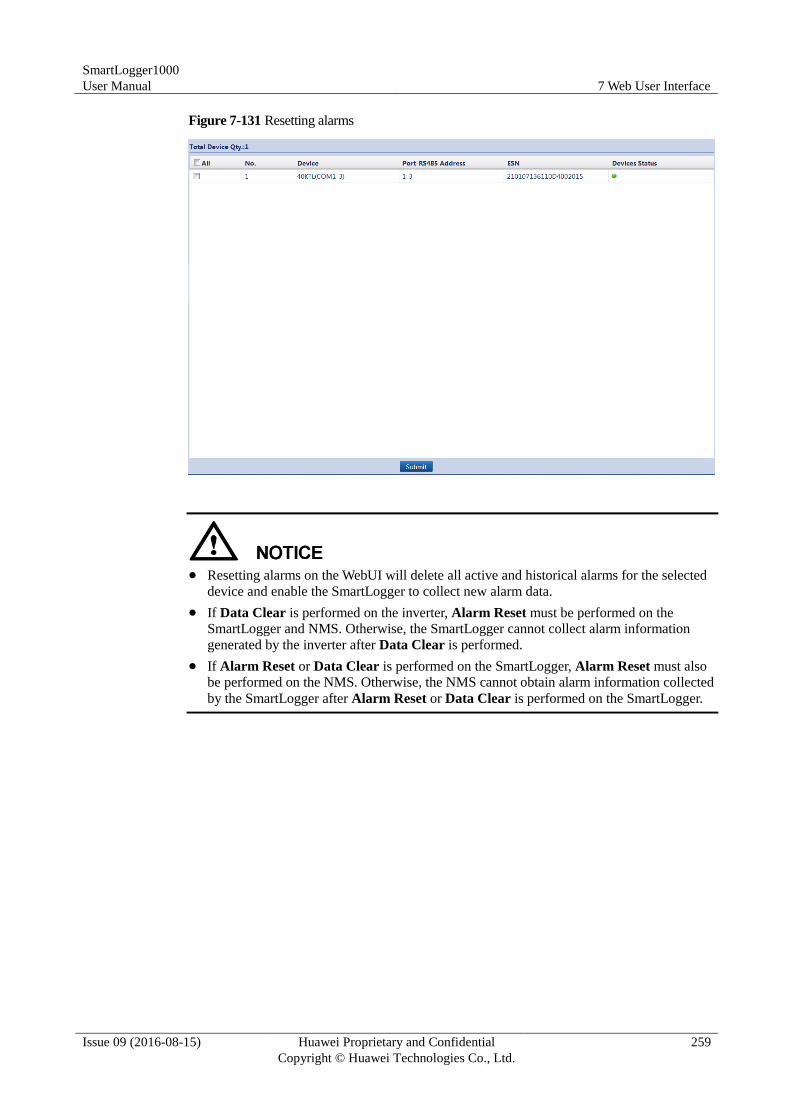
SmartLogger1000
User Manual 7 Web User Interface
Issue 09 (2016-08-15) Huawei Proprietary and Confidential
Copyright © Huawei Technologies Co., Ltd.
259
Figure 7-131 Resetting alarms
Resetting alarms on the WebUI will delete all active and historical alarms for the selected
device and enable the SmartLogger to collect new alarm data.
If Data Clear is performed on the inverter, Alarm Reset must be performed on the
SmartLogger and NMS. Otherwise, the SmartLogger cannot collect alarm information
generated by the inverter after Data Clear is performed.
If Alarm Reset or Data Clear is performed on the SmartLogger, Alarm Reset must also
be performed on the NMS. Otherwise, the NMS cannot obtain alarm information collected
by the SmartLogger after Alarm Reset or Data Clear is performed on the SmartLogger.
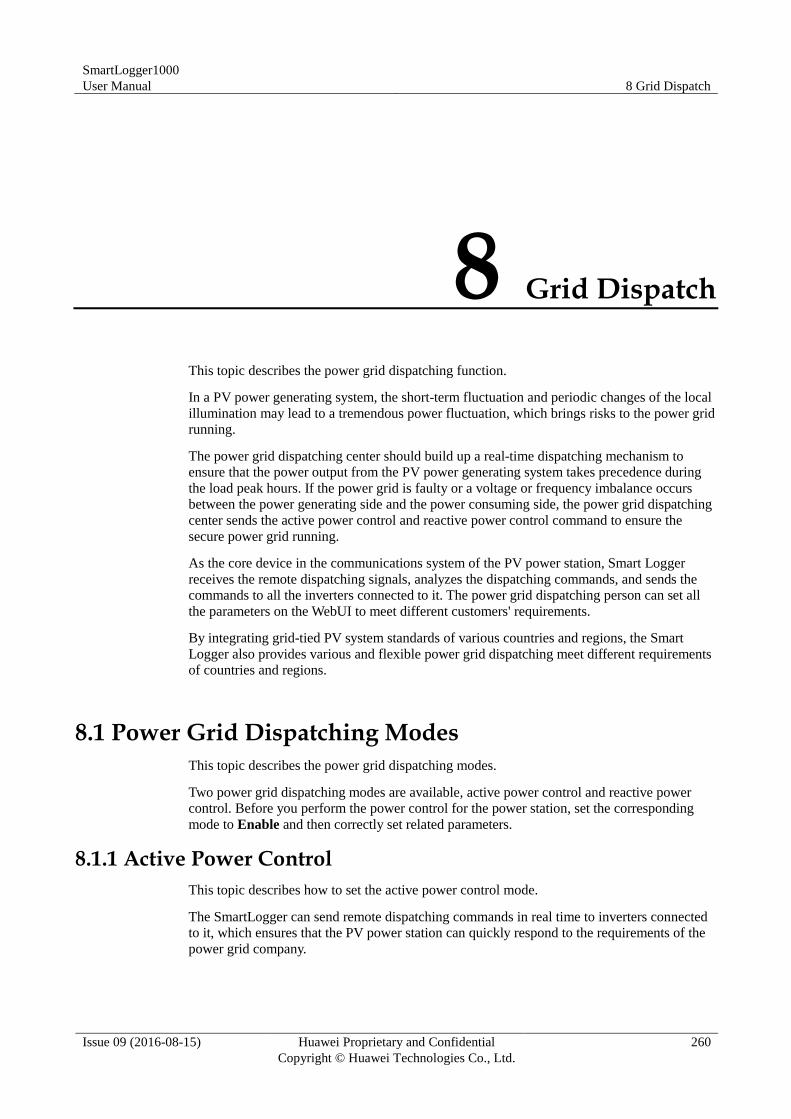
SmartLogger1000
User Manual 8 Grid Dispatch
Issue 09 (2016-08-15) Huawei Proprietary and Confidential
Copyright © Huawei Technologies Co., Ltd.
260
8 Grid Dispatch
This topic describes the power grid dispatching function.
In a PV power generating system, the short-term fluctuation and periodic changes of the local
illumination may lead to a tremendous power fluctuation, which brings risks to the power grid
running.
The power grid dispatching center should build up a real-time dispatching mechanism to
ensure that the power output from the PV power generating system takes precedence during
the load peak hours. If the power grid is faulty or a voltage or frequency imbalance occurs
between the power generating side and the power consuming side, the power grid dispatching
center sends the active power control and reactive power control command to ensure the
secure power grid running.
As the core device in the communications system of the PV power station, Smart Logger
receives the remote dispatching signals, analyzes the dispatching commands, and sends the
commands to all the inverters connected to it. The power grid dispatching person can set all
the parameters on the WebUI to meet different customers' requirements.
By integrating grid-tied PV system standards of various countries and regions, the Smart
Logger also provides various and flexible power grid dispatching meet different requirements
of countries and regions.
8.1 Power Grid Dispatching Modes
This topic describes the power grid dispatching modes.
Two power grid dispatching modes are available, active power control and reactive power
control. Before you perform the power control for the power station, set the corresponding
mode to Enable and then correctly set related parameters.
8.1.1 Active Power Control
This topic describes how to set the active power control mode.
The SmartLogger can send remote dispatching commands in real time to inverters connected
to it, which ensures that the PV power station can quickly respond to the requirements of the
power grid company.
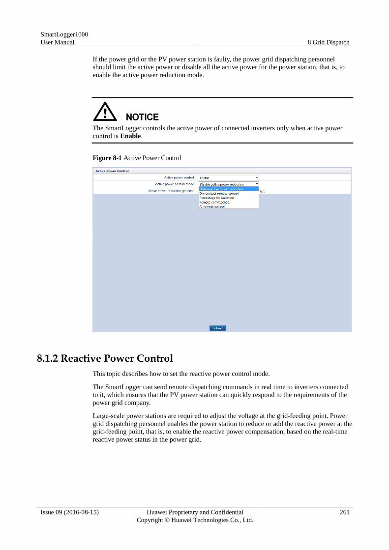
SmartLogger1000
User Manual 8 Grid Dispatch
Issue 09 (2016-08-15) Huawei Proprietary and Confidential
Copyright © Huawei Technologies Co., Ltd.
261
If the power grid or the PV power station is faulty, the power grid dispatching personnel
should limit the active power or disable all the active power for the power station, that is, to
enable the active power reduction mode.
The SmartLogger controls the active power of connected inverters only when active power
control is Enable.
Figure 8-1 Active Power Control
8.1.2 Reactive Power Control
This topic describes how to set the reactive power control mode.
The SmartLogger can send remote dispatching commands in real time to inverters connected
to it, which ensures that the PV power station can quickly respond to the requirements of the
power grid company.
Large-scale power stations are required to adjust the voltage at the grid-feeding point. Power
grid dispatching personnel enables the power station to reduce or add the reactive power at the
grid-feeding point, that is, to enable the reactive power compensation, based on the real-time
reactive power status in the power grid.
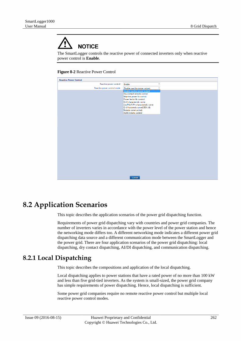
SmartLogger1000
User Manual 8 Grid Dispatch
Issue 09 (2016-08-15) Huawei Proprietary and Confidential
Copyright © Huawei Technologies Co., Ltd.
262
The SmartLogger controls the reactive power of connected inverters only when reactive
power control is Enable.
Figure 8-2 Reactive Power Control
8.2 Application Scenarios
This topic describes the application scenarios of the power grid dispatching function.
Requirements of power grid dispatching vary with countries and power grid companies. The
number of inverters varies in accordance with the power level of the power station and hence
the networking mode differs too. A different networking mode indicates a different power grid
dispatching data source and a different communication mode between the SmartLogger and
the power grid. There are four application scenarios of the power grid dispatching: local
dispatching, dry contact dispatching, AI/DI dispatching, and communication dispatching.
8.2.1 Local Dispatching
This topic describes the compositions and application of the local dispatching.
Local dispatching applies to power stations that have a rated power of no more than 100 kW
and less than five grid-tied inverters. As the system is small-sized, the power grid company
has simple requirements of power dispatching. Hence, local dispatching is sufficient.
Some power grid companies require no remote reactive power control but multiple local
reactive power control modes.
SmartLogger1000
User Manual 8 Grid Dispatch
Issue 09 (2016-08-15) Huawei Proprietary and Confidential
Copyright © Huawei Technologies Co., Ltd.
263
You can set the power control modes on the WebUI based on the actual output features. The
SmartLogger continuously controls the power output of the inverters based on the user
setting.
Figure 8-3 shows the networking application of the local dispatching.
Figure 8-3 Local dispatching
Active Power Control
The SmartLogger provides simplified local active power percentage configuration as well as
the local power control automation, that is, to automatically adjust the active power reduction
percentage in different periods of the day.
If the inverters are allowed to run overloaded, set Active Power Control Mode to
Disable active power reduction.
This function takes effect only when Active Power Control is set to Enable.
If the maximum power output of the inverters should be controlled, set Active Power
Control Mode to Percentage fix limitation.
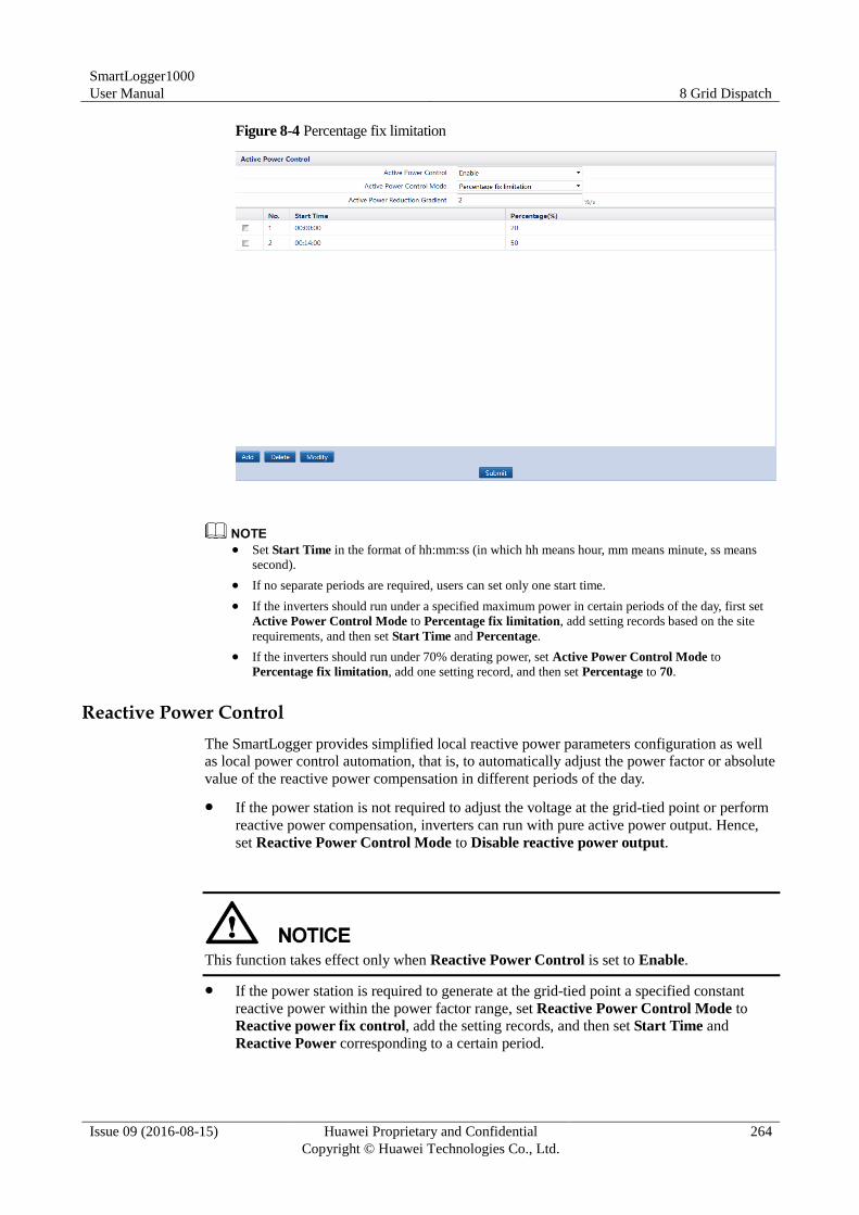
SmartLogger1000
User Manual 8 Grid Dispatch
Issue 09 (2016-08-15) Huawei Proprietary and Confidential
Copyright © Huawei Technologies Co., Ltd.
264
Figure 8-4 Percentage fix limitation
Set Start Time in the format of hh:mm:ss (in which hh means hour, mm means minute, ss means
second).
If no separate periods are required, users can set only one start time.
If the inverters should run under a specified maximum power in certain periods of the day, first set
Active Power Control Mode to Percentage fix limitation, add setting records based on the site
requirements, and then set Start Time and Percentage.
If the inverters should run under 70% derating power, set Active Power Control Mode to
Percentage fix limitation, add one setting record, and then set Percentage to 70.
Reactive Power Control
The SmartLogger provides simplified local reactive power parameters configuration as well
as local power control automation, that is, to automatically adjust the power factor or absolute
value of the reactive power compensation in different periods of the day.
If the power station is not required to adjust the voltage at the grid-tied point or perform
reactive power compensation, inverters can run with pure active power output. Hence,
set Reactive Power Control Mode to Disable reactive power output.
This function takes effect only when Reactive Power Control is set to Enable.
If the power station is required to generate at the grid-tied point a specified constant
reactive power within the power factor range, set Reactive Power Control Mode to
Reactive power fix control, add the setting records, and then set Start Time and
Reactive Power corresponding to a certain period.
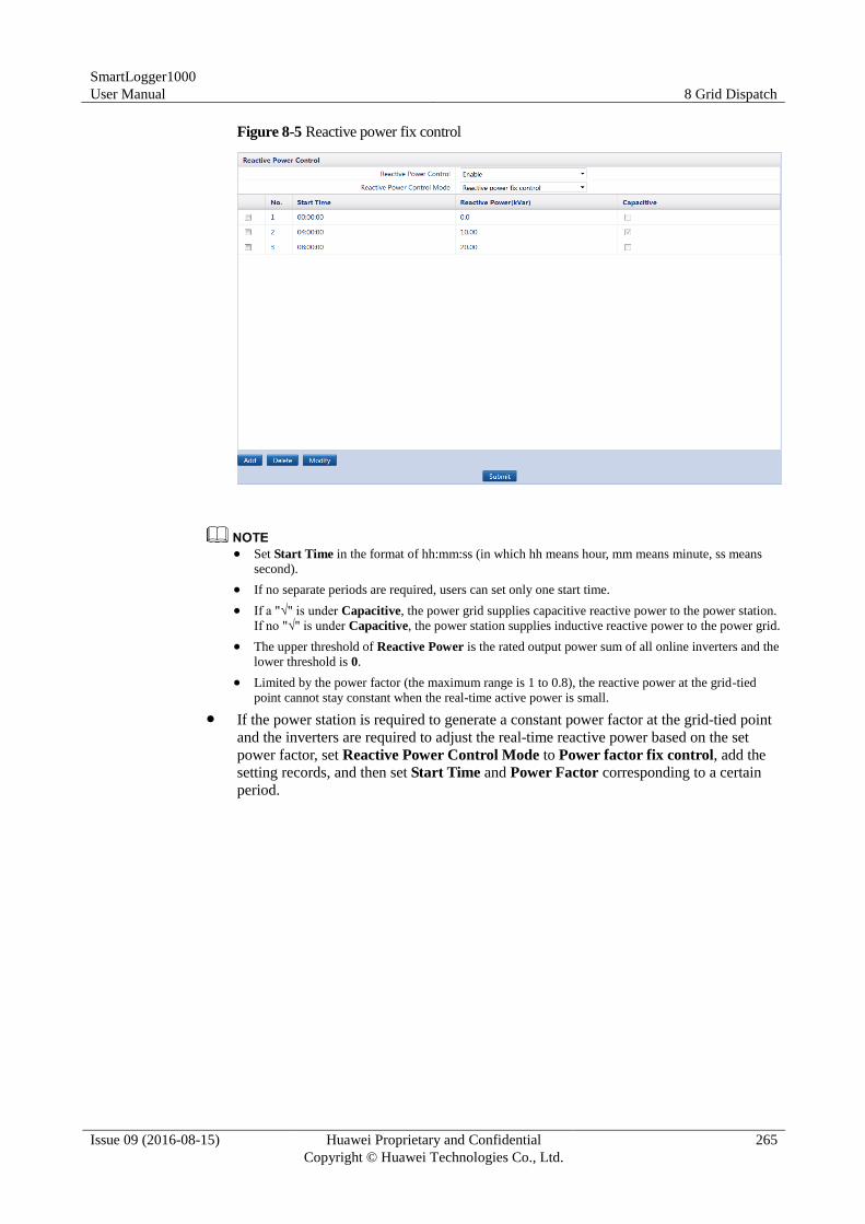
SmartLogger1000
User Manual 8 Grid Dispatch
Issue 09 (2016-08-15) Huawei Proprietary and Confidential
Copyright © Huawei Technologies Co., Ltd.
265
Figure 8-5 Reactive power fix control
Set Start Time in the format of hh:mm:ss (in which hh means hour, mm means minute, ss means
second).
If no separate periods are required, users can set only one start time.
If a "√" is under Capacitive, the power grid supplies capacitive reactive power to the power station.
If no "√" is under Capacitive, the power station supplies inductive reactive power to the power grid.
The upper threshold of Reactive Power is the rated output power sum of all online inverters and the
lower threshold is 0.
Limited by the power factor (the maximum range is 1 to 0.8), the reactive power at the grid-tied
point cannot stay constant when the real-time active power is small.
If the power station is required to generate a constant power factor at the grid-tied point
and the inverters are required to adjust the real-time reactive power based on the set
power factor, set Reactive Power Control Mode to Power factor fix control, add the
setting records, and then set Start Time and Power Factor corresponding to a certain
period.
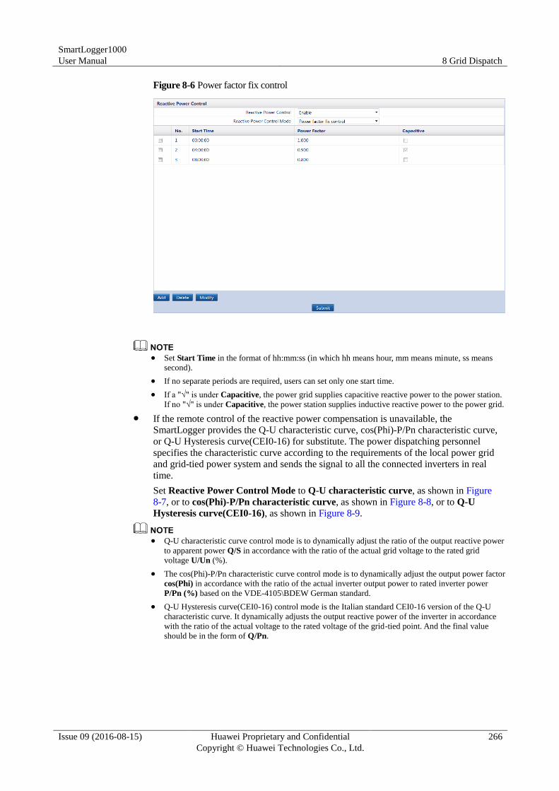
SmartLogger1000
User Manual 8 Grid Dispatch
Issue 09 (2016-08-15) Huawei Proprietary and Confidential
Copyright © Huawei Technologies Co., Ltd.
266
Figure 8-6 Power factor fix control
Set Start Time in the format of hh:mm:ss (in which hh means hour, mm means minute, ss means
second).
If no separate periods are required, users can set only one start time.
If a "√" is under Capacitive, the power grid supplies capacitive reactive power to the power station.
If no "√" is under Capacitive, the power station supplies inductive reactive power to the power grid.
If the remote control of the reactive power compensation is unavailable, the
SmartLogger provides the Q-U characteristic curve, cos(Phi)-P/Pn characteristic curve,
or Q-U Hysteresis curve(CEI0-16) for substitute. The power dispatching personnel
specifies the characteristic curve according to the requirements of the local power grid
and grid-tied power system and sends the signal to all the connected inverters in real
time.
Set Reactive Power Control Mode to Q-U characteristic curve, as shown in Figure
8-7, or to cos(Phi)-P/Pn characteristic curve, as shown in Figure 8-8, or to Q-U
Hysteresis curve(CEI0-16), as shown in Figure 8-9.
Q-U characteristic curve control mode is to dynamically adjust the ratio of the output reactive power
to apparent power Q/S in accordance with the ratio of the actual grid voltage to the rated grid
voltage U/Un (%).
The cos(Phi)-P/Pn characteristic curve control mode is to dynamically adjust the output power factor
cos(Phi) in accordance with the ratio of the actual inverter output power to rated inverter power
P/Pn (%) based on the VDE-4105\BDEW German standard.
Q-U Hysteresis curve(CEI0-16) control mode is the Italian standard CEI0-16 version of the Q-U
characteristic curve. It dynamically adjusts the output reactive power of the inverter in accordance
with the ratio of the actual voltage to the rated voltage of the grid-tied point. And the final value
should be in the form of Q/Pn.
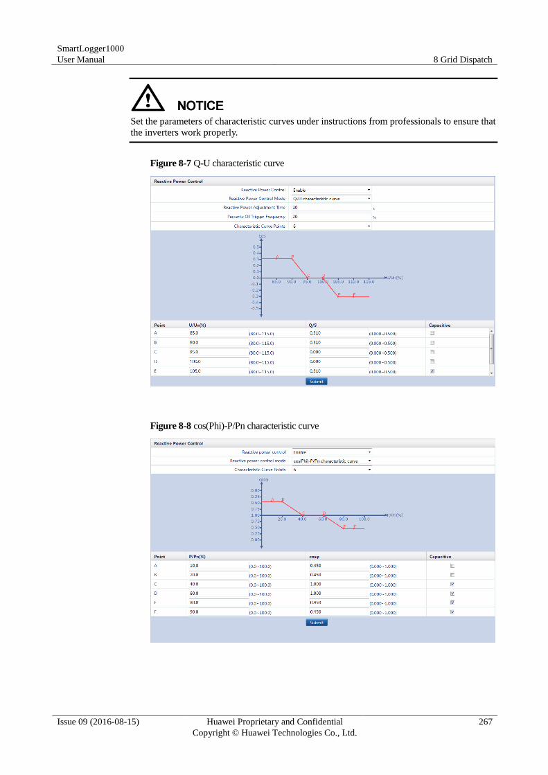
SmartLogger1000
User Manual 8 Grid Dispatch
Issue 09 (2016-08-15) Huawei Proprietary and Confidential
Copyright © Huawei Technologies Co., Ltd.
267
Set the parameters of characteristic curves under instructions from professionals to ensure that
the inverters work properly.
Figure 8-7 Q-U characteristic curve
Figure 8-8 cos(Phi)-P/Pn characteristic curve
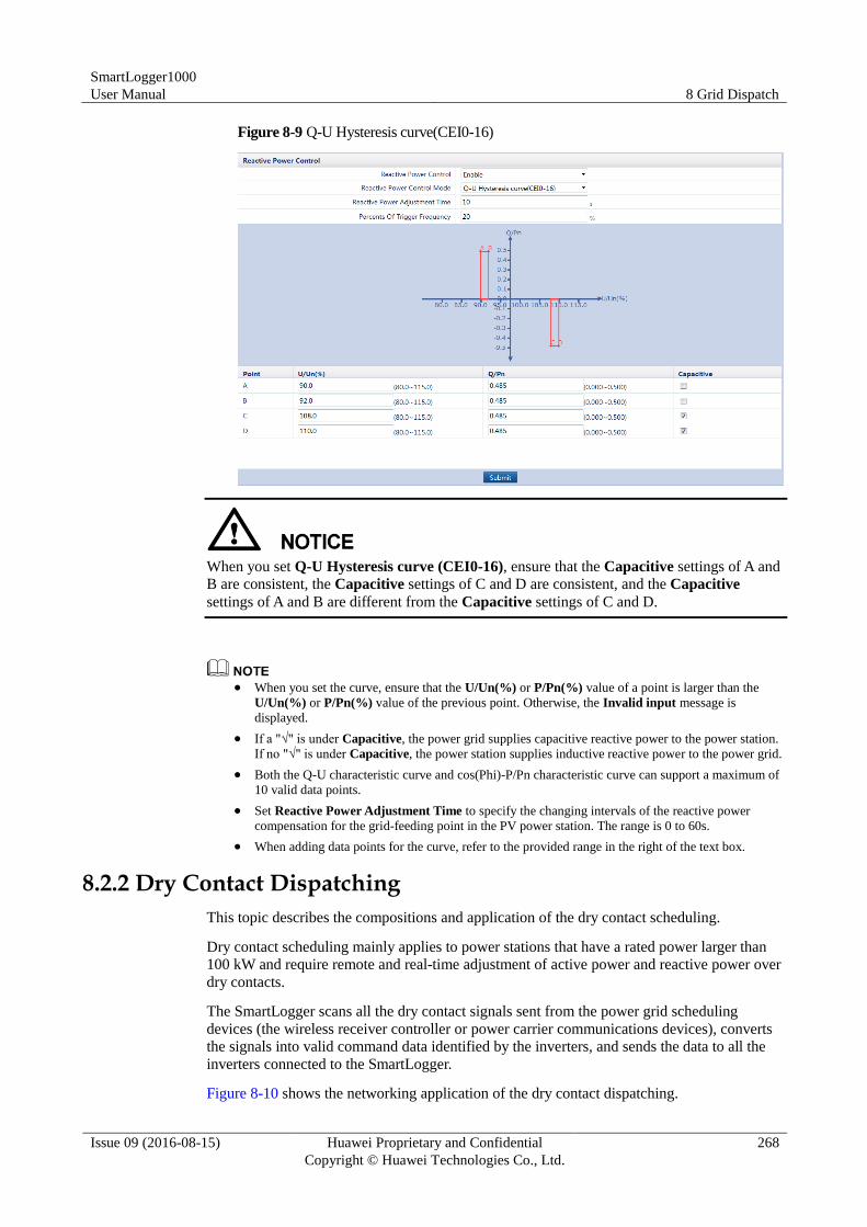
SmartLogger1000
User Manual 8 Grid Dispatch
Issue 09 (2016-08-15) Huawei Proprietary and Confidential
Copyright © Huawei Technologies Co., Ltd.
268
Figure 8-9 Q-U Hysteresis curve(CEI0-16)
When you set Q-U Hysteresis curve (CEI0-16), ensure that the Capacitive settings of A and
B are consistent, the Capacitive settings of C and D are consistent, and the Capacitive
settings of A and B are different from the Capacitive settings of C and D.
When you set the curve, ensure that the U/Un(%) or P/Pn(%) value of a point is larger than the
U/Un(%) or P/Pn(%) value of the previous point. Otherwise, the Invalid input message is
displayed.
If a "√" is under Capacitive, the power grid supplies capacitive reactive power to the power station.
If no "√" is under Capacitive, the power station supplies inductive reactive power to the power grid.
Both the Q-U characteristic curve and cos(Phi)-P/Pn characteristic curve can support a maximum of
10 valid data points.
Set Reactive Power Adjustment Time to specify the changing intervals of the reactive power
compensation for the grid-feeding point in the PV power station. The range is 0 to 60s.
When adding data points for the curve, refer to the provided range in the right of the text box.
8.2.2 Dry Contact Dispatching
This topic describes the compositions and application of the dry contact scheduling.
Dry contact scheduling mainly applies to power stations that have a rated power larger than
100 kW and require remote and real-time adjustment of active power and reactive power over
dry contacts.
The SmartLogger scans all the dry contact signals sent from the power grid scheduling
devices (the wireless receiver controller or power carrier communications devices), converts
the signals into valid command data identified by the inverters, and sends the data to all the
inverters connected to the SmartLogger.
Figure 8-10 shows the networking application of the dry contact dispatching.
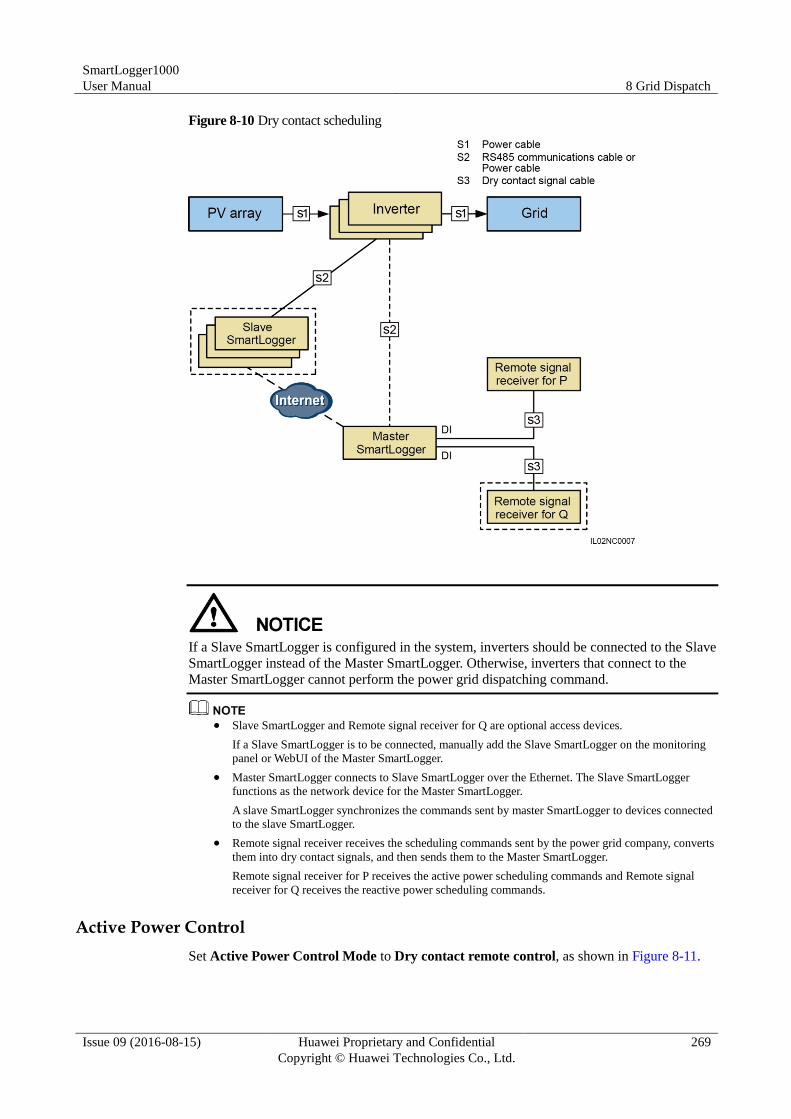
SmartLogger1000
User Manual 8 Grid Dispatch
Issue 09 (2016-08-15) Huawei Proprietary and Confidential
Copyright © Huawei Technologies Co., Ltd.
269
Figure 8-10 Dry contact scheduling
If a Slave SmartLogger is configured in the system, inverters should be connected to the Slave
SmartLogger instead of the Master SmartLogger. Otherwise, inverters that connect to the
Master SmartLogger cannot perform the power grid dispatching command.
Slave SmartLogger and Remote signal receiver for Q are optional access devices.
If a Slave SmartLogger is to be connected, manually add the Slave SmartLogger on the monitoring
panel or WebUI of the Master SmartLogger.
Master SmartLogger connects to Slave SmartLogger over the Ethernet. The Slave SmartLogger
functions as the network device for the Master SmartLogger.
A slave SmartLogger synchronizes the commands sent by master SmartLogger to devices connected
to the slave SmartLogger.
Remote signal receiver receives the scheduling commands sent by the power grid company, converts
them into dry contact signals, and then sends them to the Master SmartLogger.
Remote signal receiver for P receives the active power scheduling commands and Remote signal
receiver for Q receives the reactive power scheduling commands.
Active Power Control
Set Active Power Control Mode to Dry contact remote control, as shown in Figure 8-11.
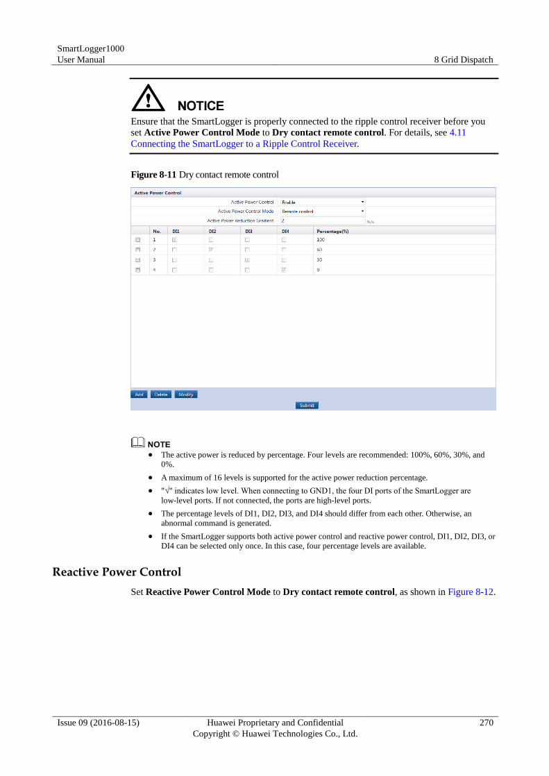
SmartLogger1000
User Manual 8 Grid Dispatch
Issue 09 (2016-08-15) Huawei Proprietary and Confidential
Copyright © Huawei Technologies Co., Ltd.
270
Ensure that the SmartLogger is properly connected to the ripple control receiver before you
set Active Power Control Mode to Dry contact remote control. For details, see 4.11
Connecting the SmartLogger to a Ripple Control Receiver.
Figure 8-11 Dry contact remote control
The active power is reduced by percentage. Four levels are recommended: 100%, 60%, 30%, and
0%.
A maximum of 16 levels is supported for the active power reduction percentage.
"√" indicates low level. When connecting to GND1, the four DI ports of the SmartLogger are
low-level ports. If not connected, the ports are high-level ports.
The percentage levels of DI1, DI2, DI3, and DI4 should differ from each other. Otherwise, an
abnormal command is generated.
If the SmartLogger supports both active power control and reactive power control, DI1, DI2, DI3, or
DI4 can be selected only once. In this case, four percentage levels are available.
Reactive Power Control
Set Reactive Power Control Mode to Dry contact remote control, as shown in Figure 8-12.
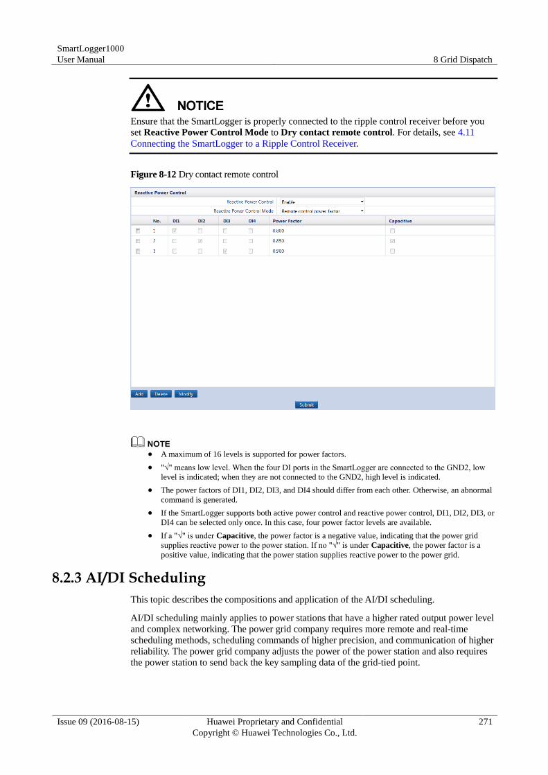
SmartLogger1000
User Manual 8 Grid Dispatch
Issue 09 (2016-08-15) Huawei Proprietary and Confidential
Copyright © Huawei Technologies Co., Ltd.
271
Ensure that the SmartLogger is properly connected to the ripple control receiver before you
set Reactive Power Control Mode to Dry contact remote control. For details, see 4.11
Connecting the SmartLogger to a Ripple Control Receiver.
Figure 8-12 Dry contact remote control
A maximum of 16 levels is supported for power factors.
"√" means low level. When the four DI ports in the SmartLogger are connected to the GND2, low
level is indicated; when they are not connected to the GND2, high level is indicated.
The power factors of DI1, DI2, DI3, and DI4 should differ from each other. Otherwise, an abnormal
command is generated.
If the SmartLogger supports both active power control and reactive power control, DI1, DI2, DI3, or
DI4 can be selected only once. In this case, four power factor levels are available.
If a "√" is under Capacitive, the power factor is a negative value, indicating that the power grid
supplies reactive power to the power station. If no "√" is under Capacitive, the power factor is a
positive value, indicating that the power station supplies reactive power to the power grid.
8.2.3 AI/DI Scheduling
This topic describes the compositions and application of the AI/DI scheduling.
AI/DI scheduling mainly applies to power stations that have a higher rated output power level
and complex networking. The power grid company requires more remote and real-time
scheduling methods, scheduling commands of higher precision, and communication of higher
reliability. The power grid company adjusts the power of the power station and also requires
the power station to send back the key sampling data of the grid-tied point.
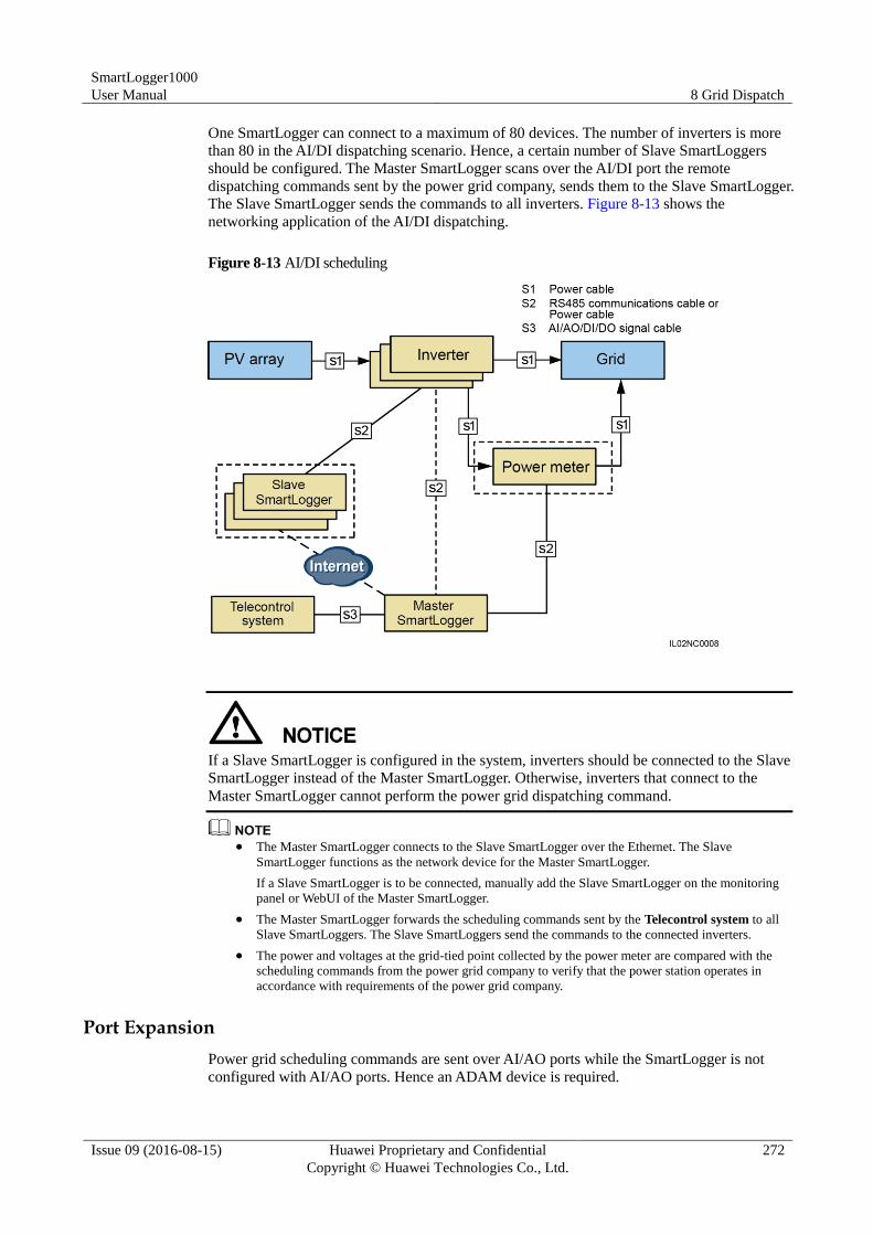
SmartLogger1000
User Manual 8 Grid Dispatch
Issue 09 (2016-08-15) Huawei Proprietary and Confidential
Copyright © Huawei Technologies Co., Ltd.
272
One SmartLogger can connect to a maximum of 80 devices. The number of inverters is more
than 80 in the AI/DI dispatching scenario. Hence, a certain number of Slave SmartLoggers
should be configured. The Master SmartLogger scans over the AI/DI port the remote
dispatching commands sent by the power grid company, sends them to the Slave SmartLogger.
The Slave SmartLogger sends the commands to all inverters. Figure 8-13 shows the
networking application of the AI/DI dispatching.
Figure 8-13 AI/DI scheduling
If a Slave SmartLogger is configured in the system, inverters should be connected to the Slave
SmartLogger instead of the Master SmartLogger. Otherwise, inverters that connect to the
Master SmartLogger cannot perform the power grid dispatching command.
The Master SmartLogger connects to the Slave SmartLogger over the Ethernet. The Slave
SmartLogger functions as the network device for the Master SmartLogger.
If a Slave SmartLogger is to be connected, manually add the Slave SmartLogger on the monitoring
panel or WebUI of the Master SmartLogger.
The Master SmartLogger forwards the scheduling commands sent by the Telecontrol system to all
Slave SmartLoggers. The Slave SmartLoggers send the commands to the connected inverters.
The power and voltages at the grid-tied point collected by the power meter are compared with the
scheduling commands from the power grid company to verify that the power station operates in
accordance with requirements of the power grid company.
Port Expansion
Power grid scheduling commands are sent over AI/AO ports while the SmartLogger is not
configured with AI/AO ports. Hence an ADAM device is required.
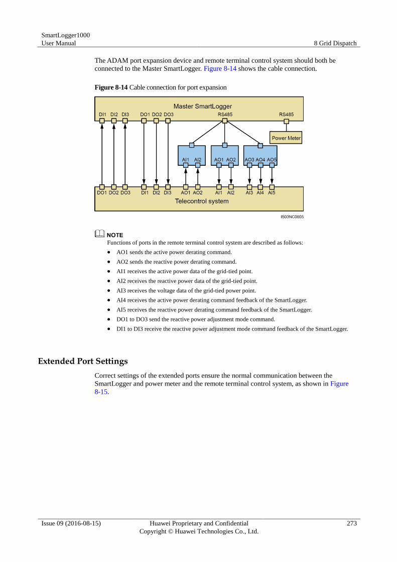
SmartLogger1000
User Manual 8 Grid Dispatch
Issue 09 (2016-08-15) Huawei Proprietary and Confidential
Copyright © Huawei Technologies Co., Ltd.
273
The ADAM port expansion device and remote terminal control system should both be
connected to the Master SmartLogger. Figure 8-14 shows the cable connection.
Figure 8-14 Cable connection for port expansion
Functions of ports in the remote terminal control system are described as follows:
AO1 sends the active power derating command.
AO2 sends the reactive power derating command.
AI1 receives the active power data of the grid-tied point.
AI2 receives the reactive power data of the grid-tied point.
AI3 receives the voltage data of the grid-tied power point.
AI4 receives the active power derating command feedback of the SmartLogger.
AI5 receives the reactive power derating command feedback of the SmartLogger.
DO1 to DO3 send the reactive power adjustment mode command.
DI1 to DI3 receive the reactive power adjustment mode command feedback of the SmartLogger.
Extended Port Settings
Correct settings of the extended ports ensure the normal communication between the
SmartLogger and power meter and the remote terminal control system, as shown in Figure
8-15.
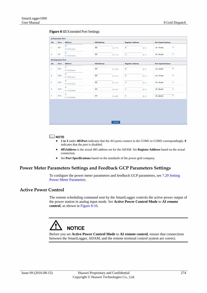
SmartLogger1000
User Manual 8 Grid Dispatch
Issue 09 (2016-08-15) Huawei Proprietary and Confidential
Copyright © Huawei Technologies Co., Ltd.
274
Figure 8-15 Extended Port Settings
1 to 3 under 485Port indicates that the AO ports connect to the COM1 to COM3 correspondingly. 0
indicates that the port is disabled.
485Address is the actual 485 address set for the ADAM. Set Register Address based on the actual
connection.
Set Port Specifications based on the standards of the power grid company.
Power Meter Parameters Settings and Feedback GCP Parameters Settings
To configure the power meter parameters and feedback GCP parameters, see 7.29 Setting
Power Meter Parameters.
Active Power Control
The remote scheduling command sent by the SmartLogger controls the active power output of
the power station in analog input mode. Set Active Power Control Mode to AI remote
control, as shown in Figure 8-16.
Before you set Active Power Control Mode to AI remote control, ensure that connections
between the SmartLogger, ADAM, and the remote terminal control system are correct.
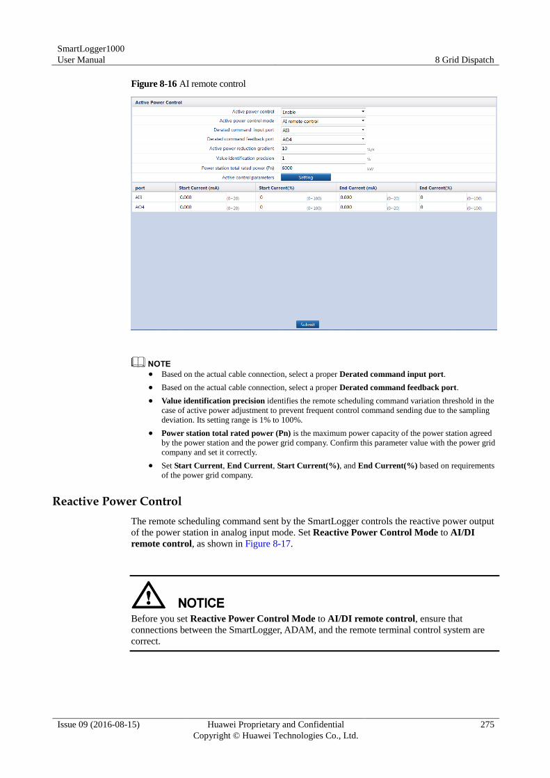
SmartLogger1000
User Manual 8 Grid Dispatch
Issue 09 (2016-08-15) Huawei Proprietary and Confidential
Copyright © Huawei Technologies Co., Ltd.
275
Figure 8-16 AI remote control
Based on the actual cable connection, select a proper Derated command input port.
Based on the actual cable connection, select a proper Derated command feedback port.
Value identification precision identifies the remote scheduling command variation threshold in the
case of active power adjustment to prevent frequent control command sending due to the sampling
deviation. Its setting range is 1% to 100%.
Power station total rated power (Pn) is the maximum power capacity of the power station agreed
by the power station and the power grid company. Confirm this parameter value with the power grid
company and set it correctly.
Set Start Current, End Current, Start Current(%), and End Current(%) based on requirements
of the power grid company.
Reactive Power Control
The remote scheduling command sent by the SmartLogger controls the reactive power output
of the power station in analog input mode. Set Reactive Power Control Mode to AI/DI
remote control, as shown in Figure 8-17.
Before you set Reactive Power Control Mode to AI/DI remote control, ensure that
connections between the SmartLogger, ADAM, and the remote terminal control system are
correct.
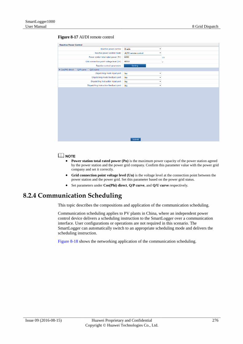
SmartLogger1000
User Manual 8 Grid Dispatch
Issue 09 (2016-08-15) Huawei Proprietary and Confidential
Copyright © Huawei Technologies Co., Ltd.
276
Figure 8-17 AI/DI remote control
Power station total rated power (Pn) is the maximum power capacity of the power station agreed
by the power station and the power grid company. Confirm this parameter value with the power grid
company and set it correctly.
Grid connection point voltage level (Un) is the voltage level at the connection point between the
power station and the power grid. Set this parameter based on the power grid status.
Set parameters under Cos(Phi) direct, Q/P curve, and Q/U curve respectively.
8.2.4 Communication Scheduling
This topic describes the compositions and application of the communication scheduling.
Communication scheduling applies to PV plants in China, where an independent power
control device delivers a scheduling instruction to the SmartLogger over a communication
interface. User configurations or operations are not required in this scenario. The
SmartLogger can automatically switch to an appropriate scheduling mode and delivers the
scheduling instruction.
Figure 8-18 shows the networking application of the communication scheduling.
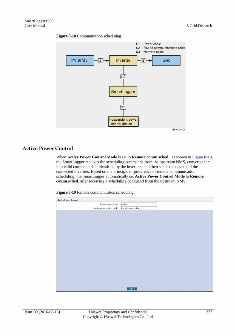
SmartLogger1000
User Manual 8 Grid Dispatch
Issue 09 (2016-08-15) Huawei Proprietary and Confidential
Copyright © Huawei Technologies Co., Ltd.
277
Figure 8-18 Communication scheduling
Active Power Control
When Active Power Control Mode is set to Remote comm.sched., as shown in Figure 8-19,
the SmartLogger receives the scheduling commands from the upstream NMS, converts them
into valid command data identified by the inverters, and then sends the data to all the
connected inverters. Based on the principle of preference of remote communication
scheduling, the SmartLogger automatically set Active Power Control Mode to Remote
comm.sched. after receiving a scheduling command from the upstream NMS.
Figure 8-19 Remote communication scheduling
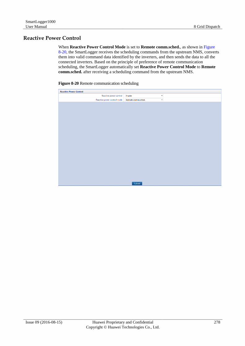
SmartLogger1000
User Manual 8 Grid Dispatch
Issue 09 (2016-08-15) Huawei Proprietary and Confidential
Copyright © Huawei Technologies Co., Ltd.
278
Reactive Power Control
When Reactive Power Control Mode is set to Remote comm.sched., as shown in Figure
8-20, the SmartLogger receives the scheduling commands from the upstream NMS, converts
them into valid command data identified by the inverters, and then sends the data to all the
connected inverters. Based on the principle of preference of remote communication
scheduling, the SmartLogger automatically set Reactive Power Control Mode to Remote
comm.sched. after receiving a scheduling command from the upstream NMS.
Figure 8-20 Remote communication scheduling
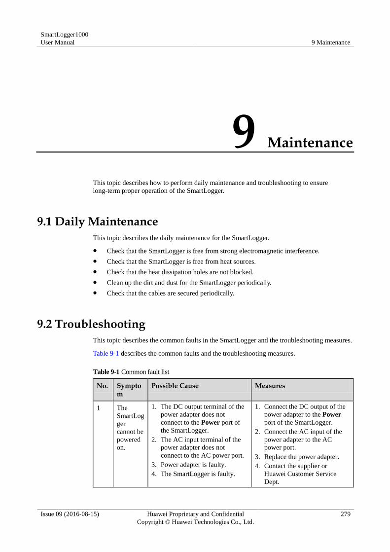
SmartLogger1000
User Manual 9 Maintenance
Issue 09 (2016-08-15) Huawei Proprietary and Confidential
Copyright © Huawei Technologies Co., Ltd.
279
9 Maintenance
This topic describes how to perform daily maintenance and troubleshooting to ensure
long-term proper operation of the SmartLogger.
9.1 Daily Maintenance
This topic describes the daily maintenance for the SmartLogger.
Check that the SmartLogger is free from strong electromagnetic interference.
Check that the SmartLogger is free from heat sources.
Check that the heat dissipation holes are not blocked.
Clean up the dirt and dust for the SmartLogger periodically.
Check that the cables are secured periodically.
9.2 Troubleshooting
This topic describes the common faults in the SmartLogger and the troubleshooting measures.
Table 9-1 describes the common faults and the troubleshooting measures.
Table 9-1 Common fault list
No. Symptom
Possible Cause Measures
1 The
SmartLog
ger
cannot be
powered
on.
1. The DC output terminal of the
power adapter does not
connect to the Power port of
the SmartLogger.
2. The AC input terminal of the
power adapter does not
connect to the AC power port.
3. Power adapter is faulty.
4. The SmartLogger is faulty.
1. Connect the DC output of the
power adapter to the Power
port of the SmartLogger.
2. Connect the AC input of the
power adapter to the AC
power port.
3. Replace the power adapter.
4. Contact the supplier or
Huawei Customer Service
Dept.
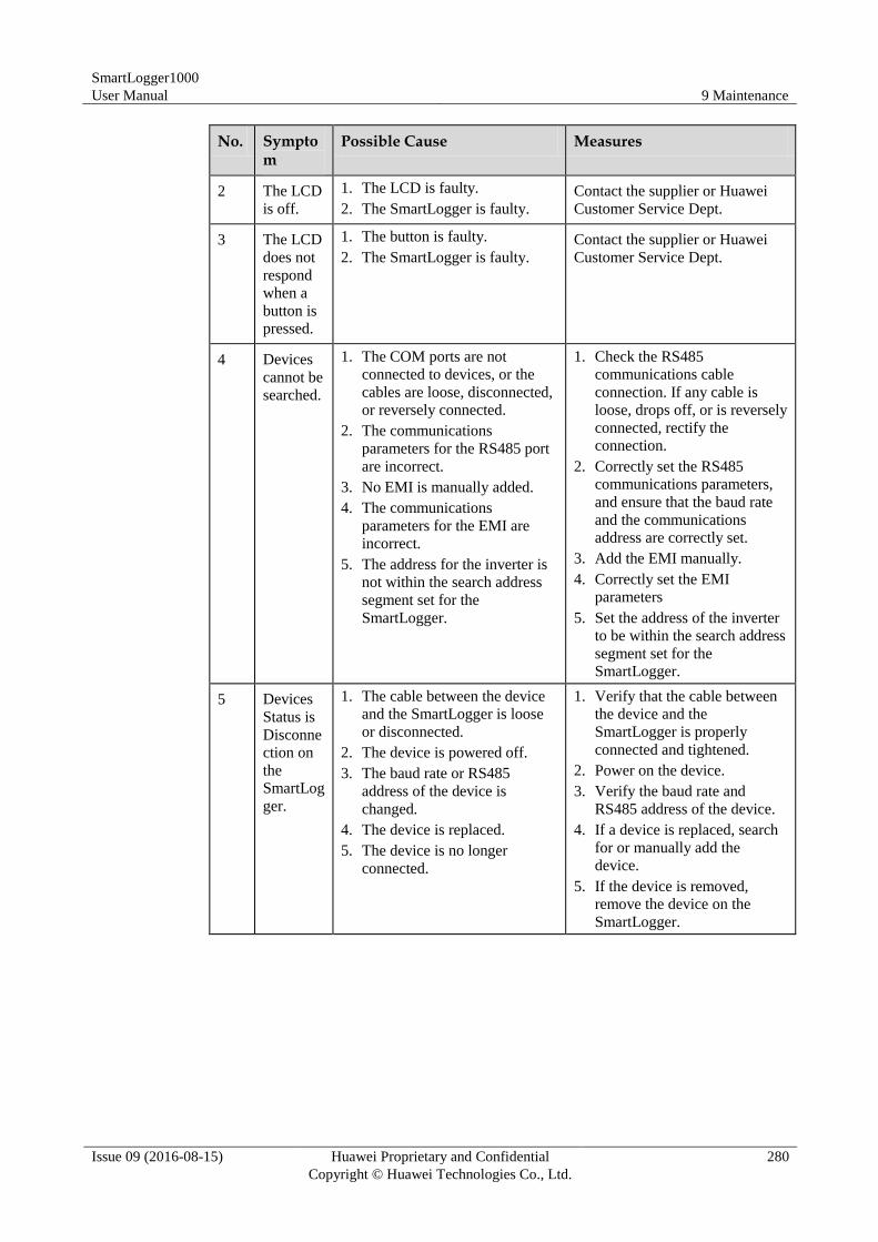
SmartLogger1000
User Manual 9 Maintenance
Issue 09 (2016-08-15) Huawei Proprietary and Confidential
Copyright © Huawei Technologies Co., Ltd.
280
No. Symptom
Possible Cause Measures
2 The LCD
is off.
1. The LCD is faulty.
2. The SmartLogger is faulty.
Contact the supplier or Huawei
Customer Service Dept.
3 The LCD
does not
respond
when a
button is
pressed.
1. The button is faulty.
2. The SmartLogger is faulty.
Contact the supplier or Huawei
Customer Service Dept.
4 Devices
cannot be
searched.
1. The COM ports are not
connected to devices, or the
cables are loose, disconnected,
or reversely connected.
2. The communications
parameters for the RS485 port
are incorrect.
3. No EMI is manually added.
4. The communications
parameters for the EMI are
incorrect.
5. The address for the inverter is
not within the search address
segment set for the
SmartLogger.
1. Check the RS485
communications cable
connection. If any cable is
loose, drops off, or is reversely
connected, rectify the
connection.
2. Correctly set the RS485
communications parameters,
and ensure that the baud rate
and the communications
address are correctly set.
3. Add the EMI manually.
4. Correctly set the EMI
parameters
5. Set the address of the inverter
to be within the search address
segment set for the
SmartLogger.
5 Devices
Status is
Disconne
ction on
the
SmartLog
ger.
1. The cable between the device
and the SmartLogger is loose
or disconnected.
2. The device is powered off.
3. The baud rate or RS485
address of the device is
changed.
4. The device is replaced.
5. The device is no longer
connected.
1. Verify that the cable between
the device and the
SmartLogger is properly
connected and tightened.
2. Power on the device.
3. Verify the baud rate and
RS485 address of the device.
4. If a device is replaced, search
for or manually add the
device.
5. If the device is removed,
remove the device on the
SmartLogger.
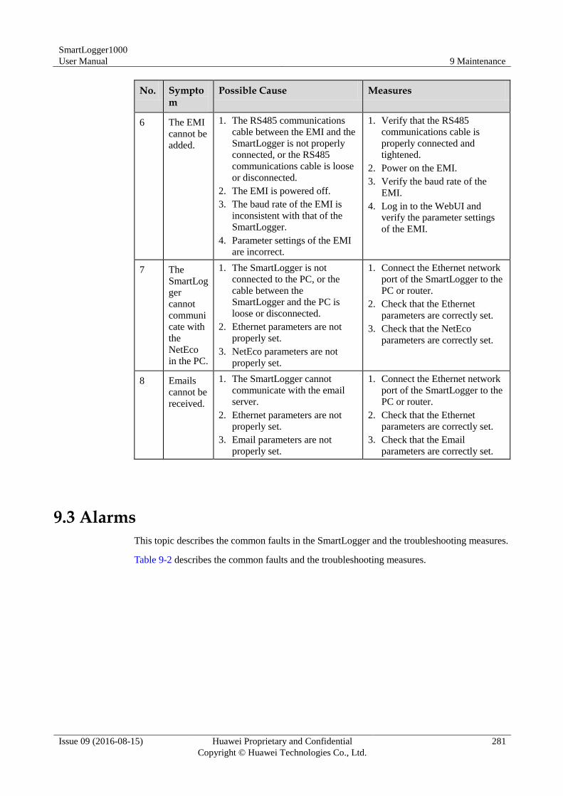
SmartLogger1000
User Manual 9 Maintenance
Issue 09 (2016-08-15) Huawei Proprietary and Confidential
Copyright © Huawei Technologies Co., Ltd.
281
No. Symptom
Possible Cause Measures
6 The EMI
cannot be
added.
1. The RS485 communications
cable between the EMI and the
SmartLogger is not properly
connected, or the RS485
communications cable is loose
or disconnected.
2. The EMI is powered off.
3. The baud rate of the EMI is
inconsistent with that of the
SmartLogger.
4. Parameter settings of the EMI
are incorrect.
1. Verify that the RS485
communications cable is
properly connected and
tightened.
2. Power on the EMI.
3. Verify the baud rate of the
EMI.
4. Log in to the WebUI and
verify the parameter settings
of the EMI.
7 The
SmartLog
ger
cannot
communi
cate with
the
NetEco
in the PC.
1. The SmartLogger is not
connected to the PC, or the
cable between the
SmartLogger and the PC is
loose or disconnected.
2. Ethernet parameters are not
properly set.
3. NetEco parameters are not
properly set.
1. Connect the Ethernet network
port of the SmartLogger to the
PC or router.
2. Check that the Ethernet
parameters are correctly set.
3. Check that the NetEco
parameters are correctly set.
8 Emails
cannot be
received.
1. The SmartLogger cannot
communicate with the email
server.
2. Ethernet parameters are not
properly set.
3. Email parameters are not
properly set.
1. Connect the Ethernet network
port of the SmartLogger to the
PC or router.
2. Check that the Ethernet
parameters are correctly set.
3. Check that the Email
parameters are correctly set.
9.3 Alarms
This topic describes the common faults in the SmartLogger and the troubleshooting measures.
Table 9-2 describes the common faults and the troubleshooting measures.
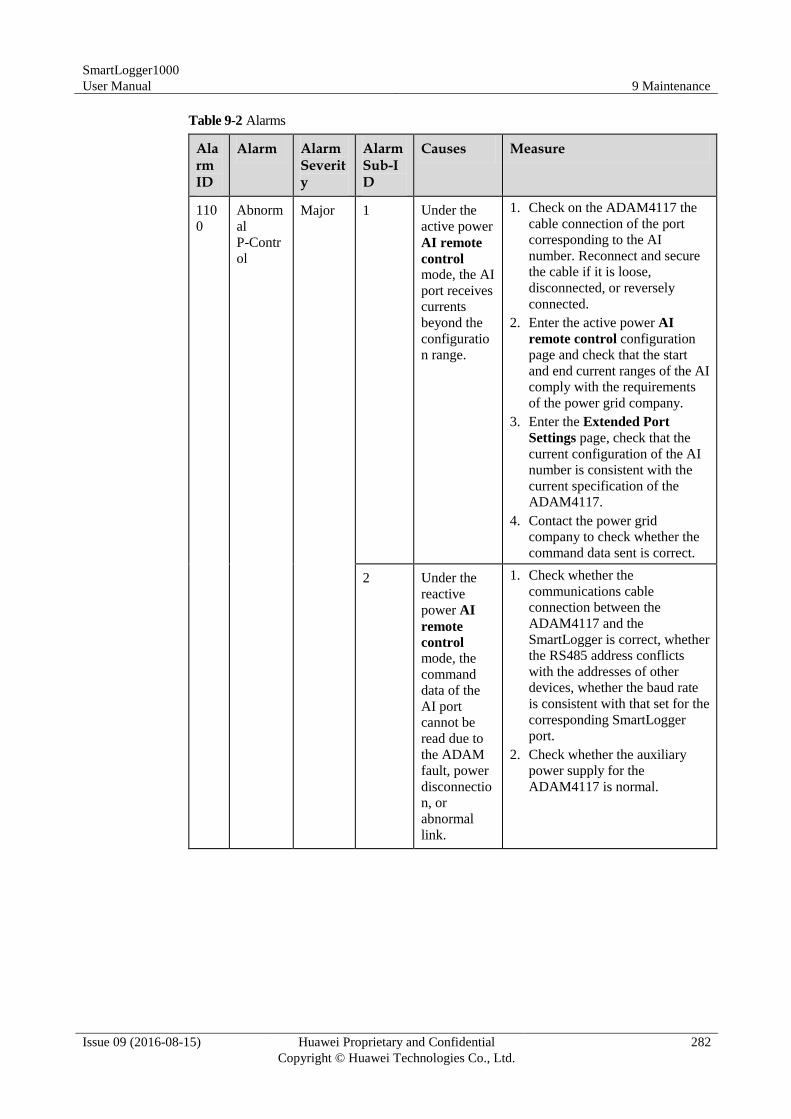
SmartLogger1000
User Manual 9 Maintenance
Issue 09 (2016-08-15) Huawei Proprietary and Confidential
Copyright © Huawei Technologies Co., Ltd.
282
Table 9-2 Alarms
Alarm ID
Alarm Alarm Severity
Alarm Sub-ID
Causes Measure
110
0
Abnorm
al
P-Contr
ol
Major 1 Under the
active power
AI remote
control mode, the AI
port receives
currents
beyond the
configuratio
n range.
1. Check on the ADAM4117 the
cable connection of the port
corresponding to the AI
number. Reconnect and secure
the cable if it is loose,
disconnected, or reversely
connected.
2. Enter the active power AI
remote control configuration
page and check that the start
and end current ranges of the AI
comply with the requirements
of the power grid company.
3. Enter the Extended Port
Settings page, check that the
current configuration of the AI
number is consistent with the
current specification of the
ADAM4117.
4. Contact the power grid
company to check whether the
command data sent is correct.
2 Under the
reactive
power AI
remote
control mode, the
command
data of the
AI port
cannot be
read due to
the ADAM
fault, power
disconnectio
n, or
abnormal
link.
1. Check whether the
communications cable
connection between the
ADAM4117 and the
SmartLogger is correct, whether
the RS485 address conflicts
with the addresses of other
devices, whether the baud rate
is consistent with that set for the
corresponding SmartLogger
port.
2. Check whether the auxiliary
power supply for the
ADAM4117 is normal.
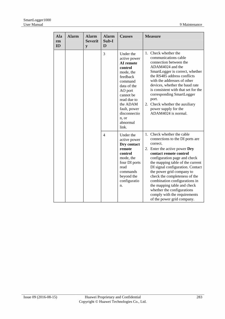
SmartLogger1000
User Manual 9 Maintenance
Issue 09 (2016-08-15) Huawei Proprietary and Confidential
Copyright © Huawei Technologies Co., Ltd.
283
Alarm ID
Alarm Alarm Severity
Alarm Sub-ID
Causes Measure
3 Under the
active power
AI remote
control mode, the
feedback
command
data of the
AO port
cannot be
read due to
the ADAM
fault, power
disconnectio
n, or
abnormal
link.
1. Check whether the
communications cable
connection between the
ADAM4024 and the
SmartLogger is correct, whether
the RS485 address conflicts
with the addresses of other
devices, whether the baud rate
is consistent with that set for the
corresponding SmartLogger
port.
2. Check whether the auxiliary
power supply for the
ADAM4024 is normal.
4 Under the
active power
Dry contact
remote
control mode, the
four DI ports
read
commands
beyond the
configuratio
n.
1. Check whether the cable
connections to the DI ports are
correct.
2. Enter the active power Dry
contact remote control configuration page and check
the mapping table of the current
DI signal configuration. Contact
the power grid company to
check the completeness of the
combination configurations in
the mapping table and check
whether the configurations
comply with the requirements
of the power grid company.
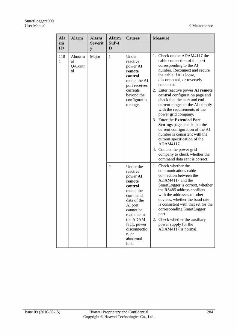
SmartLogger1000
User Manual 9 Maintenance
Issue 09 (2016-08-15) Huawei Proprietary and Confidential
Copyright © Huawei Technologies Co., Ltd.
284
Alarm ID
Alarm Alarm Severity
Alarm Sub-ID
Causes Measure
110
1
Abnorm
al
Q-Contr
ol
Major 1 Under
reactive
power AI
remote
control mode, the AI
port receives
currents
beyond the
configuratio
n range.
1. Check on the ADAM4117 the
cable connection of the port
corresponding to the AI
number. Reconnect and secure
the cable if it is loose,
disconnected, or reversely
connected.
2. Enter reactive power AI remote
control configuration page and
check that the start and end
current ranges of the AI comply
with the requirements of the
power grid company.
3. Enter the Extended Port
Settings page, check that the
current configuration of the AI
number is consistent with the
current specification of the
ADAM4117.
4. Contact the power grid
company to check whether the
command data sent is correct.
2 Under the
reactive
power AI
remote
control mode, the
command
data of the
AI port
cannot be
read due to
the ADAM
fault, power
disconnectio
n, or
abnormal
link.
1. Check whether the
communications cable
connection between the
ADAM4117 and the
SmartLogger is correct, whether
the RS485 address conflicts
with the addresses of other
devices, whether the baud rate
is consistent with that set for the
corresponding SmartLogger
port.
2. Check whether the auxiliary
power supply for the
ADAM4117 is normal.
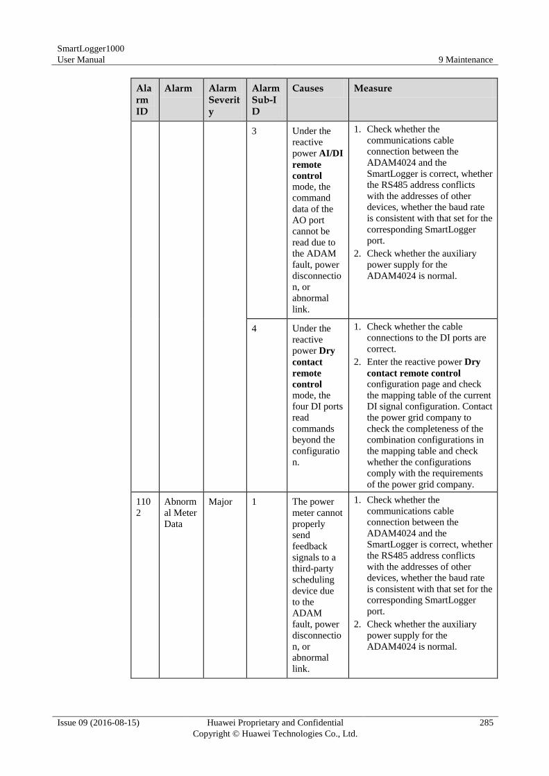
SmartLogger1000
User Manual 9 Maintenance
Issue 09 (2016-08-15) Huawei Proprietary and Confidential
Copyright © Huawei Technologies Co., Ltd.
285
Alarm ID
Alarm Alarm Severity
Alarm Sub-ID
Causes Measure
3 Under the
reactive
power AI/DI
remote
control mode, the
command
data of the
AO port
cannot be
read due to
the ADAM
fault, power
disconnectio
n, or
abnormal
link.
1. Check whether the
communications cable
connection between the
ADAM4024 and the
SmartLogger is correct, whether
the RS485 address conflicts
with the addresses of other
devices, whether the baud rate
is consistent with that set for the
corresponding SmartLogger
port.
2. Check whether the auxiliary
power supply for the
ADAM4024 is normal.
4 Under the
reactive
power Dry
contact
remote
control mode, the
four DI ports
read
commands
beyond the
configuratio
n.
1. Check whether the cable
connections to the DI ports are
correct.
2. Enter the reactive power Dry
contact remote control configuration page and check
the mapping table of the current
DI signal configuration. Contact
the power grid company to
check the completeness of the
combination configurations in
the mapping table and check
whether the configurations
comply with the requirements
of the power grid company.
110
2
Abnorm
al Meter
Data
Major 1 The power
meter cannot
properly
send
feedback
signals to a
third-party
scheduling
device due
to the
ADAM
fault, power
disconnectio
n, or
abnormal
link.
1. Check whether the
communications cable
connection between the
ADAM4024 and the
SmartLogger is correct, whether
the RS485 address conflicts
with the addresses of other
devices, whether the baud rate
is consistent with that set for the
corresponding SmartLogger
port.
2. Check whether the auxiliary
power supply for the
ADAM4024 is normal.
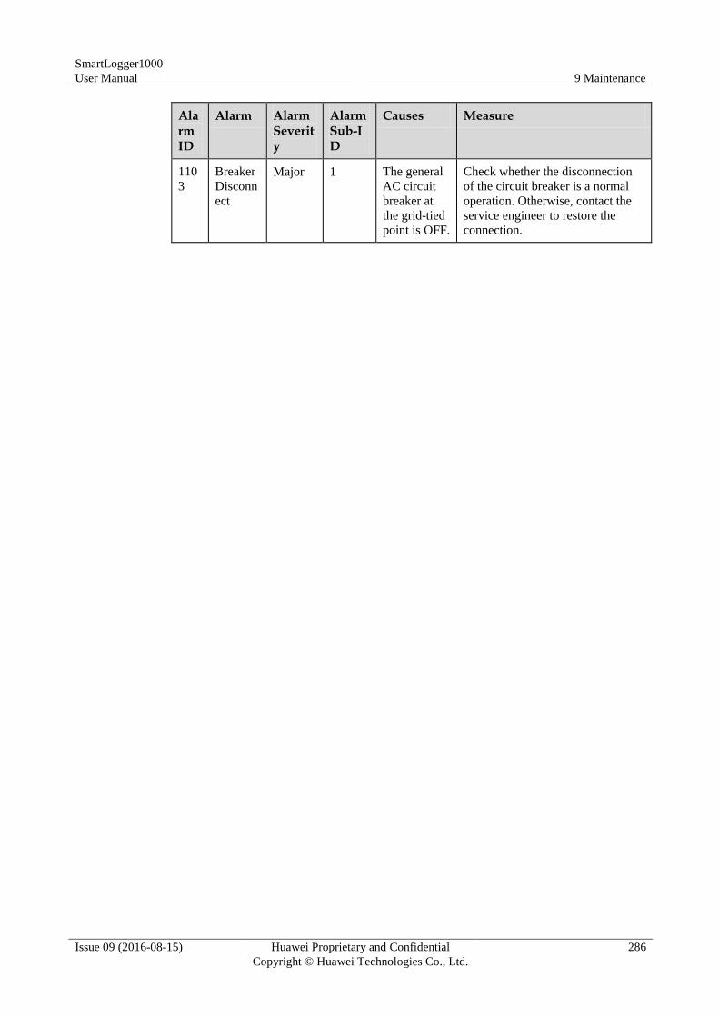
SmartLogger1000
User Manual 9 Maintenance
Issue 09 (2016-08-15) Huawei Proprietary and Confidential
Copyright © Huawei Technologies Co., Ltd.
286
Alarm ID
Alarm Alarm Severity
Alarm Sub-ID
Causes Measure
110
3
Breaker
Disconn
ect
Major 1 The general
AC circuit
breaker at
the grid-tied
point is OFF.
Check whether the disconnection
of the circuit breaker is a normal
operation. Otherwise, contact the
service engineer to restore the
connection.
SmartLogger1000
User Manual 10 Disposing of the SmartLogger
Issue 09 (2016-08-15) Huawei Proprietary and Confidential
Copyright © Huawei Technologies Co., Ltd.
287
10 Disposing of the SmartLogger
This topic describes how to dispose the SmartLogger.
If the service life of the SmartLogger expires, dispose of the SmartLogger according to the
local disposal act for waste electric appliances.
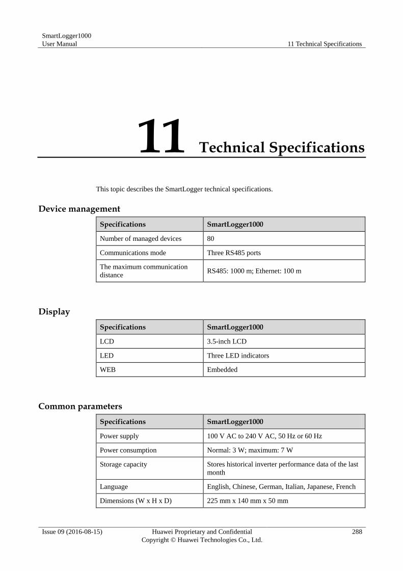
SmartLogger1000
User Manual 11 Technical Specifications
Issue 09 (2016-08-15) Huawei Proprietary and Confidential
Copyright © Huawei Technologies Co., Ltd.
288
11 Technical Specifications
This topic describes the SmartLogger technical specifications.
Device management
Specifications SmartLogger1000
Number of managed devices 80
Communications mode Three RS485 ports
The maximum communication
distance RS485: 1000 m; Ethernet: 100 m
Display
Specifications SmartLogger1000
LCD 3.5-inch LCD
LED Three LED indicators
WEB Embedded
Common parameters
Specifications SmartLogger1000
Power supply 100 V AC to 240 V AC, 50 Hz or 60 Hz
Power consumption Normal: 3 W; maximum: 7 W
Storage capacity Stores historical inverter performance data of the last
month
Language English, Chinese, German, Italian, Japanese, French
Dimensions (W x H x D) 225 mm x 140 mm x 50 mm
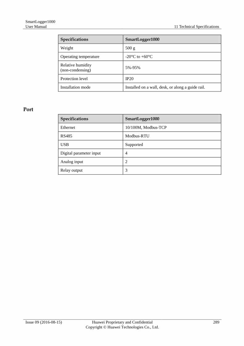
SmartLogger1000
User Manual 11 Technical Specifications
Issue 09 (2016-08-15) Huawei Proprietary and Confidential
Copyright © Huawei Technologies Co., Ltd.
289
Specifications SmartLogger1000
Weight 500 g
Operating temperature -20°C to +60°C
Relative humidity
(non-condensing) 5%-95%
Protection level IP20
Installation mode Installed on a wall, desk, or along a guide rail.
Port
Specifications SmartLogger1000
Ethernet 10/100M, Modbus-TCP
RS485 Modbus-RTU
USB Supported
Digital parameter input 4
Analog input 2
Relay output 3
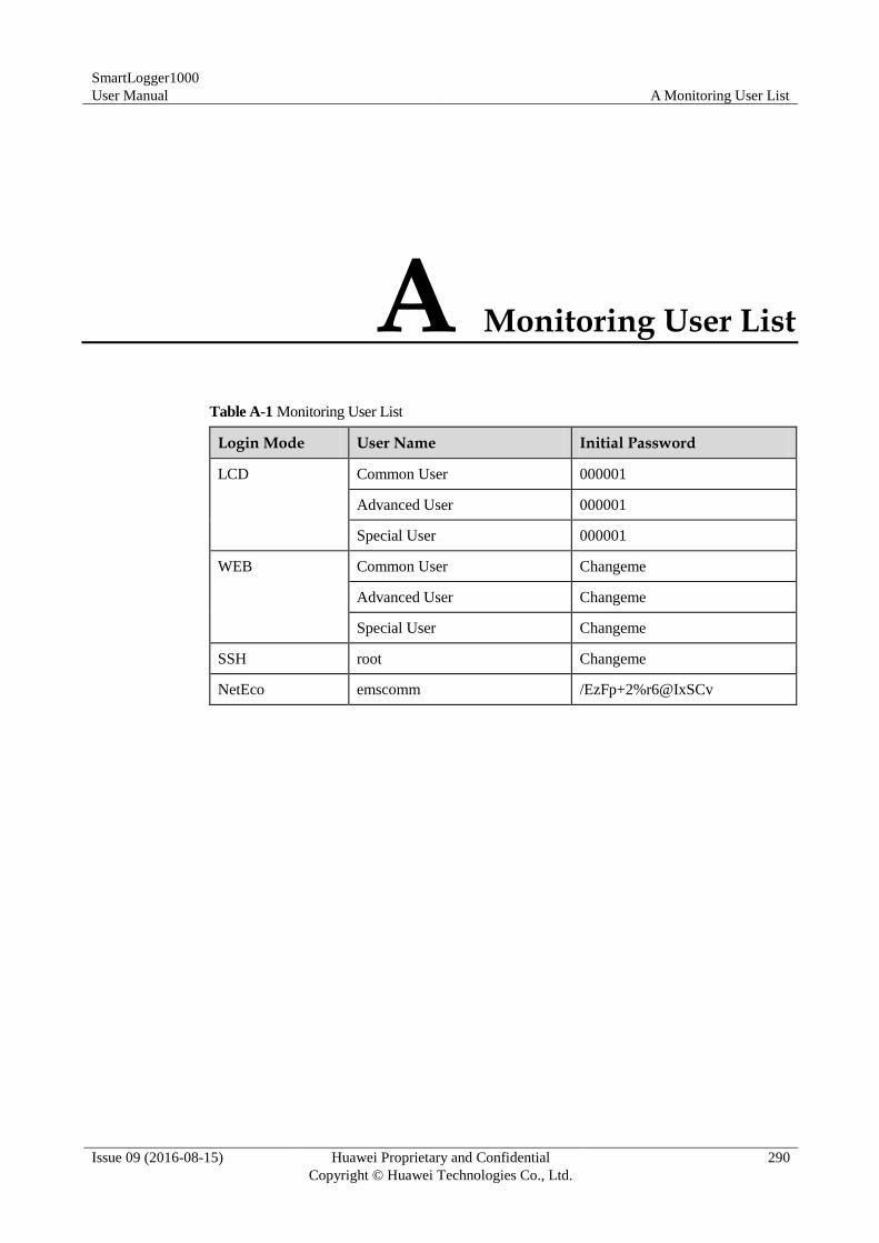
SmartLogger1000
User Manual A Monitoring User List
Issue 09 (2016-08-15) Huawei Proprietary and Confidential
Copyright © Huawei Technologies Co., Ltd.
290
A Monitoring User List
Table A-1 Monitoring User List
Login Mode User Name Initial Password
LCD Common User 000001
Advanced User 000001
Special User 000001
WEB Common User Changeme
Advanced User Changeme
Special User Changeme
SSH root Changeme
NetEco emscomm /EzFp+2%r6@IxSCv
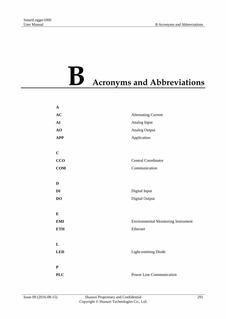
SmartLogger1000
User Manual B Acronyms and Abbreviations
Issue 09 (2016-08-15) Huawei Proprietary and Confidential
Copyright © Huawei Technologies Co., Ltd.
291
B Acronyms and Abbreviations
A
AC Alternating Current
AI Analog Input
AO Analog Output
APP Application
C
CCO Central Coordinator
COM Communication
D
DI Digital Input
DO Digital Output
E
EMI Environmental Monitoring Instrument
ETH Ethernet
L
LED Light-emitting Diode
P
PLC Power Line Communication
SmartLogger1000
User Manual B Acronyms and Abbreviations
Issue 09 (2016-08-15) Huawei Proprietary and Confidential
Copyright © Huawei Technologies Co., Ltd.
292
R
RSTP Rapid Spanning Tree Protocol
S
SFP Small Form-factor Pluggable
SPD Surge Protective Device
STA Station
STP Spanning Tree Protocol
W
WEEE Waste Electrical and Electronic Equipment