Embed Size (px)
Citation preview
1
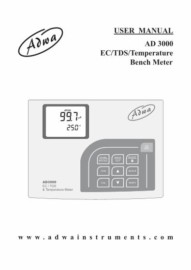
USER MANUAL
AD 3000 EC/TDS/Temperature Bench Meter
w w w . a d w a i n s t r u m e n t s . c o m
2
Dear Customer,Thank you for choosing an Adwa product. Please readcarefully this manual before starting operations.This instrument is in compliance with the EMC directive2004/108/EC and its standards, and Low VoltageDirective 2006/95/EC and its standards for electricalequipments.For more technical information, please e-mail us [email protected].
3
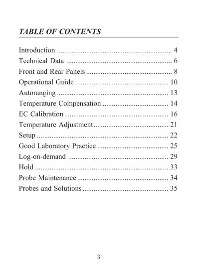
Introduction ............................................................... 4Technical Data .......................................................... 6Front and Rear Panels ............................................... 8Operational Guide ................................................... 10Autoranging ............................................................. 13Temperature Compensation .................................... 14EC Calibration ......................................................... 16Temperature Adjustment ......................................... 21Setup ........................................................................ 22Good Laboratory Practice ....................................... 25Log-on-demand ....................................................... 29Hold ......................................................................... 33Probe Maintenance .................................................. 34Probes and Solutions ............................................... 35
TABLE OF CONTENTS
4
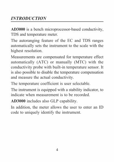
AD3000 is a bench microprocessor-based conductivity,TDS and temperature meter.The autoranging feature of the EC and TDS rangesautomatically sets the instrument to the scale with thehighest resolution.Measurements are compensated for temperature effectautomatically (ATC) or manually (MTC) with theconductivity probe with built-in temperature sensor. Itis also possible to disable the temperature compensationand measure the actual conductivity.The temperature coefficient is user selectable.The instrument is equipped with a stability indicator, toindicate when measurement is to be recorded.AD3000 includes also GLP capability.In addition, the meter allows the user to enter an IDcode to uniquely identify the instrument.
INTRODUCTION
5
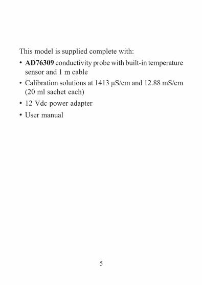
This model is supplied complete with:• AD76309 conductivity probe with built-in temperature
sensor and 1 m cable• Calibration solutions at 1413 μS/cm and 12.88 mS/cm
(20 ml sachet each)• 12 Vdc power adapter• User manual
6
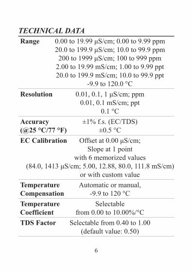
TECHNICAL DATARange 0.00 to 19.99 μS/cm; 0.00 to 9.99 ppm
20.0 to 199.9 μS/cm; 10.0 to 99.9 ppm200 to 1999 μS/cm; 100 to 999 ppm
2.00 to 19.99 mS/cm; 1.00 to 9.99 ppt20.0 to 199.9 mS/cm; 10.0 to 99.9 ppt
-9.9 to 120.0 °CResolution 0.01, 0.1, 1 μS/cm; ppm
0.01, 0.1 mS/cm; ppt0.1 °C
Accuracy ±1% f.s. (EC/TDS)(@25 °C/77 °F) ±0.5 °CEC Calibration Offset at 0.00 μS/cm;
Slope at 1 pointwith 6 memorized values
(84.0, 1413 μS/cm; 5.00, 12.88, 80.0, 111.8 mS/cm)or with custom value
Temperature Automatic or manual,Compensation -9.9 to 120 °CTemperature SelectableCoefficient from 0.00 to 10.00%/°CTDS Factor Selectable from 0.40 to 1.00
(default value: 0.50)
7
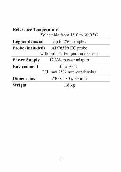
Reference TemperatureSelectable from 15.0 to 30.0 °C
Log-on-demand Up to 250 samplesProbe (included) AD76309 EC probe
with built-in temperature sensorPower Supply 12 Vdc power adapterEnvironment 0 to 50 °C
RH max 95% non-condensingDimensions 230 x 180 x 50 mmWeight 1.8 kg
8
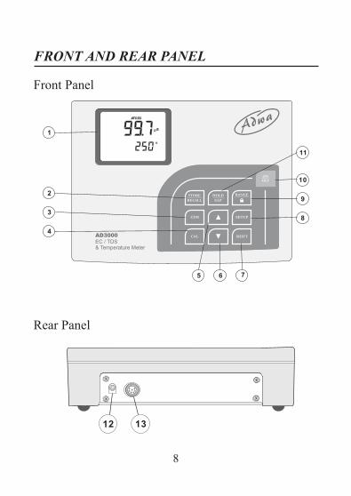
Front Panel
Rear Panel
FRONT AND REAR PANEL
9
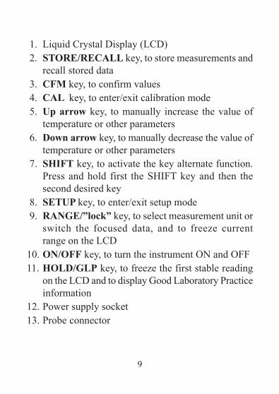
1. Liquid Crystal Display (LCD)2. STORE/RECALL key, to store measurements and
recall stored data3. CFM key, to confirm values4. CAL key, to enter/exit calibration mode5. Up arrow key, to manually increase the value of
temperature or other parameters6. Down arrow key, to manually decrease the value of
temperature or other parameters7. SHIFT key, to activate the key alternate function.
Press and hold first the SHIFT key and then thesecond desired key
8. SETUP key, to enter/exit setup mode9. RANGE/”lock” key, to select measurement unit or
switch the focused data, and to freeze currentrange on the LCD
10. ON/OFF key, to turn the instrument ON and OFF11. HOLD/GLP key, to freeze the first stable reading
on the LCD and to display Good Laboratory Practiceinformation
12. Power supply socket13. Probe connector
10
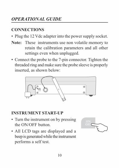
CONNECTIONS• Plug the 12 Vdc adapter into the power supply socket.Note: These instruments use non volatile memory to
retain the calibration parameters and all othersettings even when unplugged.
• Connect the probe to the 7-pin connector. Tighten thethreaded ring and make sure the probe sleeve is properlyinserted, as shown below:
INSTRUMENT START-UP• Turn the instrument on by pressing
the ON/OFF button.• All LCD tags are displayed and a
beep is generated while the instrumentperforms a self test.
OPERATIONAL GUIDE
11
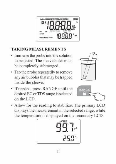
TAKING MEASUREMENTS• Immerse the probe into the solution
to be tested. The sleeve holes mustbe completely submerged.
• Tap the probe repeatedly to removeany air bubbles that may be trappedinside the sleeve.
• If needed, press RANGE until thedesired EC or TDS range is selectedon the LCD.
• Allow for the reading to stabilize. The primary LCDdisplays the measurement in the selected range, whilethe temperature is displayed on the secondary LCD.
12
Notes:• If the meter displays only dashes "----", the reading
is out of range.• If the stability indicator (hourglass symbol) blinks,
the reading is not stable.• Make sure the meter is calibrated before taking
measurements.• If measurements are taken successively in different
samples, for accurate reading it is recommendedto rinse the probe thoroughly with deionizedwater before immersing it into the sample.
• TDS reading is obtained by multiplying the ECreading by the TDS factor, which has a defaultvalue of 0.50. It is possible to change the TDSfactor within the 0.40 to 1.00 range by enteringsetup mode and selecting the "tdS" item (see“Setup” section for details).
13
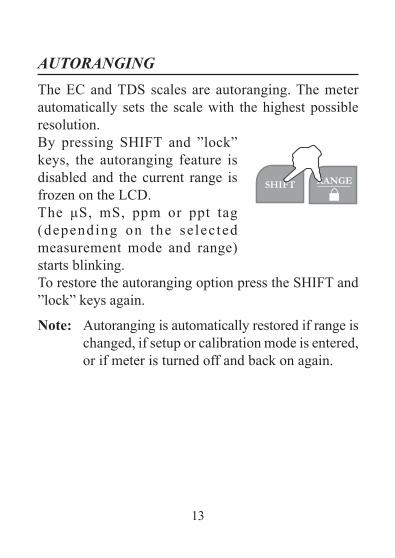
AUTORANGINGThe EC and TDS scales are autoranging. The meterautomatically sets the scale with the highest possibleresolution.By pressing SHIFT and ”lock”keys, the autoranging feature isdisabled and the current range isfrozen on the LCD.The μS, mS, ppm or ppt tag(depending on the se lectedmeasurement mode and range)starts blinking.To restore the autoranging option press the SHIFT and”lock” keys again.
Note: Autoranging is automatically restored if range ischanged, if setup or calibration mode is entered,or if meter is turned off and back on again.
14
TEMPERATURE COMPENSATION
Three options are available for temperature compensation:1. Automatic (ATC): the EC probe features a built-in
temperature sensor, which provides the temperaturereading to automatically compensate the EC/TDSmeasurement (from -9.9 to 120.0°C), also using theselected reference temperature.
2. Manual (MTC): the temperature value can be manuallyset using the arrow keys. The compensation is referencedto the selected reference temperature. While in MTCmode, the °C tag blinks on the secondary LCD.
3. No compensation (NOTC): the temperature is nottaken into account. The reading displayed on the pri-mary LCD is the actual EC or TDS value.
Notes:• The default compensation mode is ATC.• Temperature compensation setting can be accessed
by entering the setup mode and selecting the"tcE" item (see “Setup” section for details).
15
• If the temperature compensation is active,measurements are compensated using thetemperature coefficient (default value 1.90 %/°C).To change the temperature coefficient, enter thesetup mode and select the “tc” item (see “Setup”section for details).
• If the temperature reading is out of the -9.9 to120.0 °C interval and the ATC option is selected,the temperature full scale value will be displayed,together with the °C tag blinking. No temperaturecompensation will be performed.
• The reference temperature can be set from 15to 30 °C. When the reference temperature ischanged, the temperature coefficient must bemanually adjusted by the user.For example, if α is the coefficient with referencetemperature of 25 °C, if changing the temperatureto 20 °C, the new coefficient can be calculatedwith the following formula:
β=α/(1-α/20)If α=1.90%/°C, then β=2.10%/°C.
• Always set reference temperature to 25 °Cwhen measuring TDS.
16
EC CALIBRATION
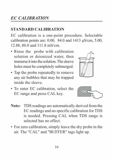
STANDARD CALIBRATIONEC calibration is a one-point procedure. Selectablecalibration points are: 0.00, 84.0 and 1413 μS/cm, 5.00,12.88, 80.0 and 111.8 mS/cm.• Rinse the probe with calibration
solution or deionized water, thenimmerse it into the solution. The sleeveholes must be completely submerged.
• Tap the probe repeatedly to removeany air bubbles that may be trappedinside the sleeve.
• To enter EC calibration, select theEC range and press CAL key.
Note: TDS readings are automatically derived from theEC readings and no specific calibration for TDSis needed. Pressing CAL when TDS range isselected has no effect.
• For zero calibration, simply leave the dry probe in theair. The "CAL" and "BUFFER" tags light up.
17
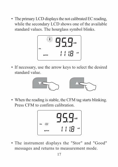
• The primary LCD displays the not calibrated EC reading,while the secondary LCD shows one of the availablestandard values. The hourglass symbol blinks.
• If necessary, use the arrow keys to select the desiredstandard value.
• When the reading is stable, the CFM tag starts blinking.Press CFM to confirm calibration.
• The instrument displays the "Stor" and "Good"messages and returns to measurement mode.
18
Notes:• If the temperature is out of range, the "WRONG
BUFFER TEMP" message blinks on the LCD. If thereading is too far from the expected value, "WRONGBUFFER" blinks.
• For best results choose a standard value for calibrationclose to the sample to be measured.
• During standard calibration the meter uses 1.90%/°Ccompensation coefficient . If the setup item "tc" hasbeen set to different value, when exiting calibrationmode, the displayed valued on the upper LCD mightbe different from the nominal standard value.
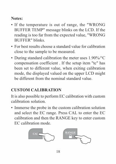
CUSTOM CALIBRATIONIt is also possible to perform EC calibration with customcalibration solution.• Immerse the probe in the custom calibration solution
and select the EC range. Press CAL to enter the ECcalibration and then the RANGE key to enter customEC calibration mode.
19
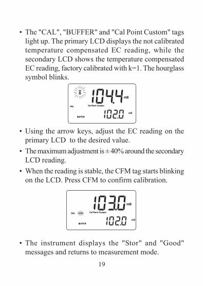
• The "CAL", "BUFFER" and "Cal Point Custom" tagslight up. The primary LCD displays the not calibratedtemperature compensated EC reading, while thesecondary LCD shows the temperature compensatedEC reading, factory calibrated with k=1. The hourglasssymbol blinks.
• Using the arrow keys, adjust the EC reading on theprimary LCD to the desired value.
• The maximum adjustment is ± 40% around the secondaryLCD reading.
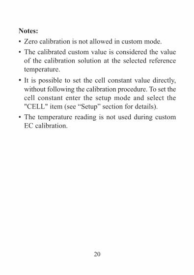
• When the reading is stable, the CFM tag starts blinkingon the LCD. Press CFM to confirm calibration.
• The instrument displays the "Stor" and "Good"messages and returns to measurement mode.
20
Notes:• Zero calibration is not allowed in custom mode.• The calibrated custom value is considered the value
of the calibration solution at the selected referencetemperature.
• It is possible to set the cell constant value directly,without following the calibration procedure. To set thecell constant enter the setup mode and select the"CELL" item (see “Setup” section for details).
• The temperature reading is not used during customEC calibration.
21
TEMPERATURE ADJUSTMENT
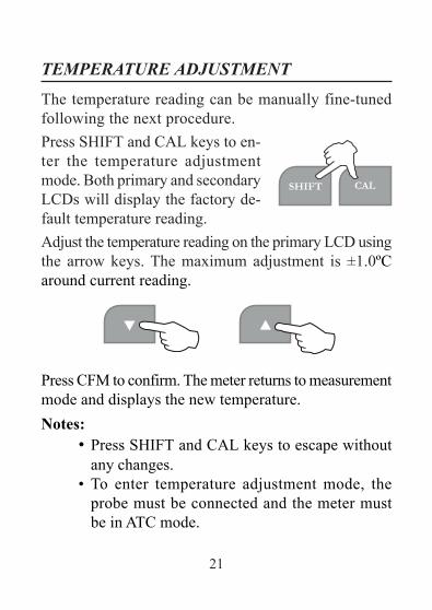
The temperature reading can be manually fine-tunedfollowing the next procedure.Press SHIFT and CAL keys to en-ter the temperature adjustmentmode. Both primary and secondaryLCDs will display the factory de-fault temperature reading.Adjust the temperature reading on the primary LCD usingthe arrow keys. The maximum adjustment is ±1.0ºCaround current reading.
Press CFM to confirm. The meter returns to measurementmode and displays the new temperature.Notes:
• Press SHIFT and CAL keys to escape withoutany changes.
• To enter temperature adjustment mode, theprobe must be connected and the meter mustbe in ATC mode.
22
SETUP
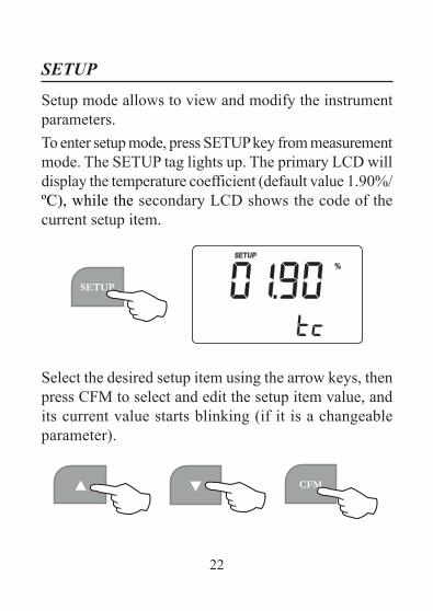
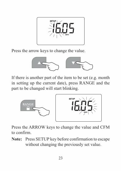
Setup mode allows to view and modify the instrumentparameters.To enter setup mode, press SETUP key from measurementmode. The SETUP tag lights up. The primary LCD willdisplay the temperature coefficient (default value 1.90%/ºC), while the secondary LCD shows the code of thecurrent setup item.
Select the desired setup item using the arrow keys, thenpress CFM to select and edit the setup item value, andits current value starts blinking (if it is a changeableparameter).
23
Press the arrow keys to change the value.
If there is another part of the item to be set (e.g. monthin setting up the current date), press RANGE and thepart to be changed will start blinking.
Press the ARROW keys to change the value and CFMto confirm.Note: Press SETUP key before confirmation to escape
without changing the previously set value.
24
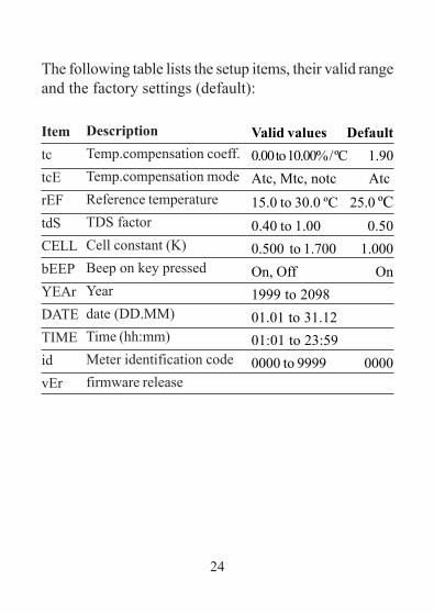
The following table lists the setup items, their valid rangeand the factory settings (default):
ItemtctcErEFtdSCELLbEEPYEArDATETIMEidvEr
DescriptionTemp.compensation coeff.Temp.compensation modeReference temperatureTDS factorCell constant (K)Beep on key pressedYeardate (DD.MM)Time (hh:mm)Meter identification codefirmware release
Valid values Default0.00 to 10.00% / ºC 1.90Atc, Mtc, notc Atc
15.0 to 30.0 ºC 25.0 ºC0.40 to 1.00 0.500.500 to 1.700 1.000On, Off On1999 to 209801.01 to 31.1201:01 to 23:590000 to 9999 0000
25
GOOD LABORATORY PRACTICE
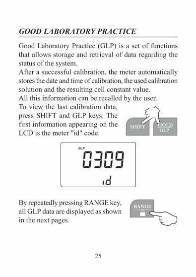
Good Laboratory Practice (GLP) is a set of functionsthat allows storage and retrieval of data regarding thestatus of the system.After a successful calibration, the meter automaticallystores the date and time of calibration, the used calibrationsolution and the resulting cell constant value.All this information can be recalled by the user.To view the last calibration data,press SHIFT and GLP keys. Thefirst information appearing on theLCD is the meter "id" code.
By repeatedly pressing RANGE key,all GLP data are displayed as shownin the next pages.
26
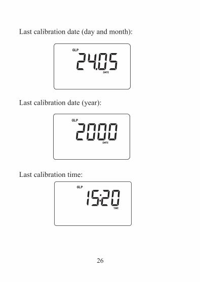
Last calibration date (day and month):
Last calibration date (year):
Last calibration time:
27
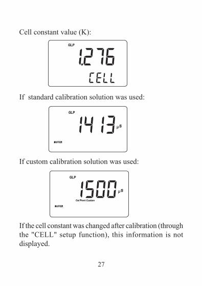
Cell constant value (K):
If standard calibration solution was used:
If custom calibration solution was used:
If the cell constant was changed after calibration (throughthe "CELL" setup function), this information is notdisplayed.
28
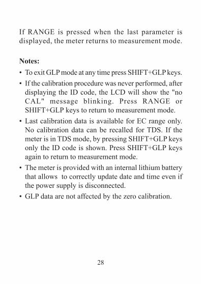
If RANGE is pressed when the last parameter isdisplayed, the meter returns to measurement mode.
Notes:• To exit GLP mode at any time press SHIFT+GLP keys.• If the calibration procedure was never performed, after
displaying the ID code, the LCD will show the "noCAL" message blinking. Press RANGE orSHIFT+GLP keys to return to measurement mode.
• Last calibration data is available for EC range only.No calibration data can be recalled for TDS. If themeter is in TDS mode, by pressing SHIFT+GLP keysonly the ID code is shown. Press SHIFT+GLP keysagain to return to measurement mode.
• The meter is provided with an internal lithium batterythat allows to correctly update date and time even ifthe power supply is disconnected.
• GLP data are not affected by the zero calibration.
29
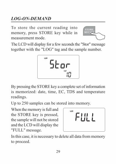
LOG-ON-DEMAND
To store the current reading intomemory, press STORE key while inmeasurement mode.The LCD will display for a few seconds the "Stor" messagetogether with the "LOG" tag and the sample number.
By pressing the STORE key a complete set of informationis memorized: date, time, EC, TDS and temperaturereadings.Up to 250 samples can be stored into memory.When the memory is full andthe STORE key is pressed,the sample will not be storedand the LCD will display the"FULL" message.In this case, it is necessary to delete all data from memoryto proceed.
30
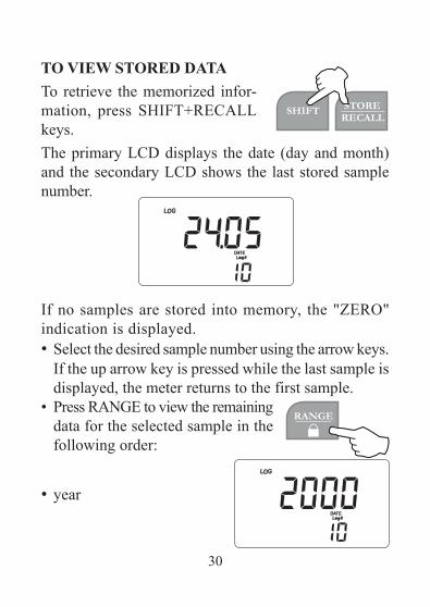
TO VIEW STORED DATATo retrieve the memorized infor-mation, press SHIFT+RECALLkeys.The primary LCD displays the date (day and month)and the secondary LCD shows the last stored samplenumber.
If no samples are stored into memory, the "ZERO"indication is displayed.• Select the desired sample number using the arrow keys.
If the up arrow key is pressed while the last sample isdisplayed, the meter returns to the first sample.
• Press RANGE to view the remainingdata for the selected sample in thefollowing order:
• year
31
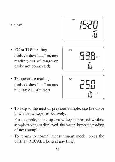
• time
• EC or TDS reading(only dashes "----" meansreading out of range orprobe not connected)
• Temperature reading(only dashes "----" meansreading out of range)
• To skip to the next or previous sample, use the up ordown arrow keys respectively.For example, if the up arrow key is pressed while asample reading is displayed, the meter shows the readingof next sample.
• To return to normal measurement mode, press theSHIFT+RECALL keys at any time.
32
TO DELETE STORED DATAThe meter allows to delete a single sample or all thememory at one time.To delete a single sample proceed as follows:• Enter the viewing stored data mode and select the
desired sample number.• Press the HOLD key. "dEL" and
"CFM" will start blinking.• Press CFM to confirm deletion.Note: Press HOLD key again to escape without
deleting data. When scrolling through storeddata, if a deleted sample is selected, the meterwill display the "nuLL" message.
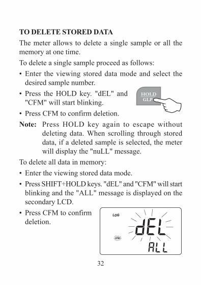
To delete all data in memory:• Enter the viewing stored data mode.• Press SHIFT+HOLD keys. "dEL" and "CFM" will start
blinking and the "ALL" message is displayed on thesecondary LCD.
• Press CFM to confirmdeletion.
33
Note: Press SHIFT+HOLD keys to escape withoutdeleting data.If no samples are stored in memory and a deletionis attempted, the meter shows the "Zero" messageand then returns to measurement mode.
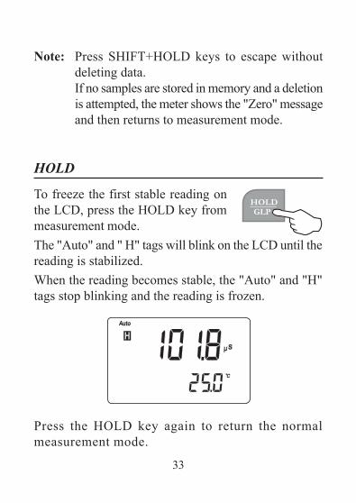
To freeze the first stable reading onthe LCD, press the HOLD key frommeasurement mode.The "Auto" and " H" tags will blink on the LCD until thereading is stabilized.When the reading becomes stable, the "Auto" and "H"tags stop blinking and the reading is frozen.
Press the HOLD key again to return the normalmeasurement mode.
HOLD
34
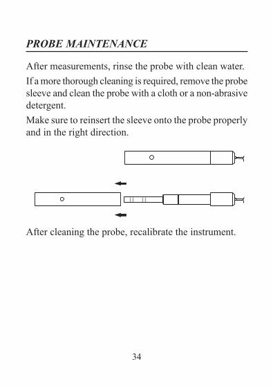
PROBE MAINTENANCE
After measurements, rinse the probe with clean water.If a more thorough cleaning is required, remove the probesleeve and clean the probe with a cloth or a non-abrasivedetergent.Make sure to reinsert the sleeve onto the probe properlyand in the right direction.
After cleaning the probe, recalibrate the instrument.
35
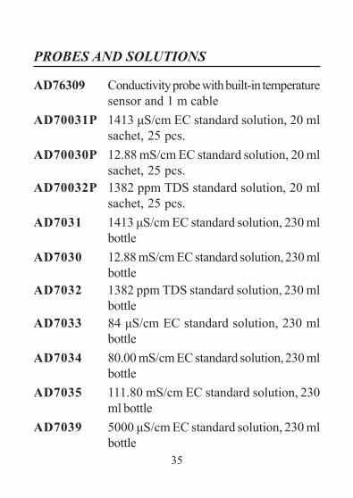
PROBES AND SOLUTIONS
AD76309 Conductivity probe with built-in temperaturesensor and 1 m cable
AD70031P 1413 μS/cm EC standard solution, 20 mlsachet, 25 pcs.
AD70030P 12.88 mS/cm EC standard solution, 20 mlsachet, 25 pcs.
AD70032P 1382 ppm TDS standard solution, 20 mlsachet, 25 pcs.
AD7031 1413 μS/cm EC standard solution, 230 mlbottle
AD7030 12.88 mS/cm EC standard solution, 230 mlbottle
AD7032 1382 ppm TDS standard solution, 230 mlbottle
AD7033 84 μS/cm EC standard solution, 230 mlbottle
AD7034 80.00 mS/cm EC standard solution, 230 mlbottle
AD7035 111.80 mS/cm EC standard solution, 230ml bottle
AD7039 5000 μS/cm EC standard solution, 230 mlbottle
36
MANAD3000 09/14
ADWA INSTRUMENTS Kft.Alsókikötõ sor 11, 6726 Szeged, Hungary
Tel. +36 62 317 878Fax +36 62 550 610
e-mail: [email protected]