Embed Size (px)
Citation preview
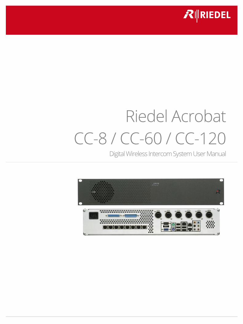
Riedel Acrobat CC-8 / CC-60 / CC-120
Digital Wireless Intercom System User Manual
User Manual Acrobat CC-8 / CC-60 / CC-120 V4.2
2
Harmonised standards applied
Directive 1999/5/EC: Radio and Telecommunication Terminal Equipment
EN 50385:2002 EMF EN 60950-1:2006 Safety
EN 55022:2006+A1:2007 ClassB EMC, Emission ITE Residential Environment EN 61000-6-2:2005 EMC, Immunity in industrial area
EN 301 406 V1.5.1 DECT Access EN 301 489-1 V1.8.1 EMC & Radio spectrum Matters for radio Equipment
EN 301 489-6 V1.3.1 EMC & Radio spectrum Matters for radio Equipment (DECT Equipment)
Other standards or national regulations: FCC CFR 47, P.15 Class B Radio frequency devices, radiated Emission
This device complies with Part 15 of the FCC rules and with RSS-210 of Industry Canada.
Operation is subject to the following two conditions:
1. this device may not cause harmful interference, and 2. this device must accept any interference received, including interference that may cause undesired operation.
3. Changes or modifications made to this equipment not expressly approved by Riedel may void the FCC authorization to operate this equipment. This device is tested and fulfils the Radio Standards Specification RSS-213 Issue 2.
This device complies with FCC Part 15 Subpart D, unlicensed personal communication devices. Frequency band: 1920-1930 MHz.
Type of Modulation: multi carrier time division multiple access with Digital modulation (GFSK). Number of channels: 5 RF Channels, 5x12=60TDMA Duplex channels.
Antenna information: 2 permanent attached antennas, no external connector. RF Power: max. +20,5dBm.
NOTE: This equipment has been tested and found to comply with the limits for a Class B digital device, pursuant to Part 15 of the FCC Rules. These limits are designed to
provide reasonable protection against harmful interference in a residential installation. This equipment generates, uses and can radiate radio frequency energy and, if not installed and used in accordance with the instructions, may cause harmful interference to radio communications. However, there is no guarantee that interference will not occur in a particular installation. If this equipment does cause harmful interference to radio or television reception, which can be determined by turning the equipment off
and on, the user is encouraged to try to correct the interference by one or more of the following measures: • Reorient or relocate the receiving antenna.
• Increase the separation between the equipment and receiver. • Connect the equipment into an outlet on a circuit different from that to which the receiver is connected.
• Consult the dealer or an experienced radio/TV technician for help. Radiofrequency radiation exposure Information:
This equipment complies with FCC radiation exposure limits set forth for an uncontrolled environment. This equipment should be installed and operated with minimum distance of 20 cm between the radiator and your body. This transmitter must not be co-located or operating in conjunction with any other antenna or transmitter.
© 2014 Riedel Communications GmbH & Co KG. All rights reserved. Under the copyright laws, this manual may not be copied, in whole or in part, without the written consent of Riedel. Every effort has been made to ensure that the information in this manual is accurate. Riedel is not responsible for printing or clerical errors. All trademarks are the property of their respective owners.
User Manual Acrobat CC-8 / CC-60 / CC-120 V4.2
3
CONTENT 1 Safety Information ...............................................................................................................................................5
1.1 Explanations of Symbols................................................................................................................................................................ 5 1.1.1 Danger .................................................................................................................................................................................. 5 1.1.2 Warning ................................................................................................................................................................................ 5 1.1.3 Caution ................................................................................................................................................................................. 5 1.1.4 Hint........................................................................................................................................................................................ 5
1.2 Service .............................................................................................................................................................................................. 6 1.3 Voltage ............................................................................................................................................................................................. 6 1.4 Environment.................................................................................................................................................................................... 6 1.5 Battery Safety .................................................................................................................................................................................. 7 1.6 CE Declaration of Conformity........................................................................................................................................................ 7 1.7 Disposal............................................................................................................................................................................................ 7
2 Introduction ..........................................................................................................................................................8 2.1 General............................................................................................................................................................................................. 8 2.2 Terminology..................................................................................................................................................................................... 8 2.3 Document Scope............................................................................................................................................................................. 8 2.4 Network Concept ............................................................................................................................................................................ 9 2.5 Overview of reserved networks .................................................................................................................................................... 9 2.6 Synchronization via Ethernet (acc. IEEE1588)............................................................................................................................10 2.7 WBM (Web Based Management) related issues.......................................................................................................................13
2.7.1 Supported Web Browser ..................................................................................................................................................13 2.7.2 General WBM issues .........................................................................................................................................................13 2.7.3 Simultaneous WBM sessions ...........................................................................................................................................13 2.7.4 Marking changed values...................................................................................................................................................13 2.7.5 Sorting of Tables................................................................................................................................................................14
2.8 Partition concept of Cell Antenna and Cell Controller .............................................................................................................14 2.9 Releasenotes .................................................................................................................................................................................14 2.10 System limits .................................................................................................................................................................................14
3 User elements.....................................................................................................................................................15 3.1 ACROBAT CC-8...............................................................................................................................................................................15
3.1.1 User Elements front ..........................................................................................................................................................15 3.1.2 User Elements rear............................................................................................................................................................16
3.2 ACROBAT CC-60 / CC-120.............................................................................................................................................................21 3.2.1 User Elements Front .........................................................................................................................................................21 3.2.2 User Elements Rear...........................................................................................................................................................22 3.2.3 Ethernet connectors "Gb1", "Gb2" (Pos. 6).....................................................................................................................23 3.2.4 MADI boards (Pos. 7).........................................................................................................................................................23 3.2.5 Ethernet Cabling instructions ..........................................................................................................................................23 3.2.6 MADI cabling instructions ................................................................................................................................................23
3.3 ACROBAT CA-6...............................................................................................................................................................................24 3.3.1 User elements front ..........................................................................................................................................................24 3.3.2 User elements rear ...........................................................................................................................................................24 3.3.3 PoE Connector ...................................................................................................................................................................25
3.4 Factory reset of Cell Antenna ......................................................................................................................................................25 3.5 LED States of Cell Antenna ..........................................................................................................................................................26
4 Quick Start Cell Controller (Example CC-8)......................................................................................................27 4.1 Quick start overview.....................................................................................................................................................................27 4.2 Example Configuration ................................................................................................................................................................28 4.3 Prepare and connect hardware ..................................................................................................................................................28 4.4 Maintenance PC ............................................................................................................................................................................29 4.5 Cell Controller initial access.........................................................................................................................................................29 4.6 IP (Infrastructure) network ..........................................................................................................................................................30 4.7 Devices/DECT network .................................................................................................................................................................31 4.8 Load license file.............................................................................................................................................................................32 4.9 Scan devices ..................................................................................................................................................................................34 4.10 Audio board...................................................................................................................................................................................35 4.11 Acrobat Cell Antenna....................................................................................................................................................................36
4.11.1 General ...............................................................................................................................................................................36 4.11.2 Synchronization.................................................................................................................................................................37
4.12 Wireless Beltpacks ........................................................................................................................................................................38 4.13 Partyline Configuration (Beltpack)..............................................................................................................................................40 4.14 Partyline Configuration (Audioboard users)..............................................................................................................................41 4.15 System services (Automatic start)...............................................................................................................................................43 4.16 "Quick Start" Completion.............................................................................................................................................................43 4.17 Further steps .................................................................................................................................................................................44
4.17.1 Radio frequency site survey.............................................................................................................................................44 4.17.2 Synchronization implementation....................................................................................................................................44
User Manual Acrobat CC-8 / CC-60 / CC-120 V4.2
4
5 Configuration reference ....................................................................................................................................45 5.1 WBM overview...............................................................................................................................................................................45
5.1.1 Different WBM modes ......................................................................................................................................................45 5.1.2 Features in WBM mode Riedel Admin ............................................................................................................................45 5.1.3 WBM related differences CC-8 / CC-60/CC-120 .............................................................................................................45 5.1.4 Login to WBM.....................................................................................................................................................................46 5.1.5 General objects..................................................................................................................................................................48 5.1.6 Changing values.................................................................................................................................................................49
5.2 "Administration" Configuration ..................................................................................................................................................50 5.2.1 Frame Configuration.........................................................................................................................................................51 5.2.2 Frame Program Info..........................................................................................................................................................54
5.3 "Network/Gateways" Configuration ...........................................................................................................................................56 5.3.1 Gateway configuration .....................................................................................................................................................57 5.3.2 Network configuration......................................................................................................................................................57
5.4 "Partylines" Configuration ...........................................................................................................................................................60 5.5 "Devices" Configuration ...............................................................................................................................................................62
5.5.1 Configuration Page "Devices - Base"...............................................................................................................................63 5.5.2 Configuration Page "Devices - Beltpack" ........................................................................................................................64 5.5.3 Configuration Page "Devices - Audioboard" ..................................................................................................................66 5.5.4 Configuration Page "Devices - Sync" ...............................................................................................................................67 5.5.5 Configuration Page "Devices - About" ............................................................................................................................68 5.5.6 Configuration Page "Devices - Debug" (Advanced mode)............................................................................................70 5.5.7 General Device configuration ..........................................................................................................................................70
5.6 "Debugging" Configuration..........................................................................................................................................................74 5.7 "Status" Configuration..................................................................................................................................................................77
5.7.1 General Status Information..............................................................................................................................................78 5.7.2 Configuration Page "Status - Modules 1" .......................................................................................................................78 5.7.3 Configuration Page "Status - Modules 2" .......................................................................................................................81 5.7.4 Configuration Page "Status - Calls Dect" ........................................................................................................................83 5.7.5 Configuration Page "Status - RSSI" ..................................................................................................................................85
5.8 "System" Configuration................................................................................................................................................................87 6 Configuration techniques and technologies ...................................................................................................88
6.1 Technologies..................................................................................................................................................................................88 6.1.1 CC-60/CC-120 MADI Channel assignment......................................................................................................................88 6.1.2 SNMP...................................................................................................................................................................................89 6.1.3 SNMP - Configuration Options ........................................................................................................................................90 6.1.4 Implementation Details ....................................................................................................................................................90 6.1.5 SNMP MIB tree...................................................................................................................................................................90 6.1.6 SNMP Trap Tree.................................................................................................................................................................91
6.2 Ethernet Synchronization (acc. IEEE1588) .................................................................................................................................93 6.2.1 Timezone Support.............................................................................................................................................................94
7 Troubleshooting / FAQ.......................................................................................................................................95 7.1 DECT ...............................................................................................................................................................................................95
7.1.1 Cell Antenna is not found using "Scan" ..........................................................................................................................95 7.2 Audioboard at CC-8 ......................................................................................................................................................................95
7.2.1 No Audio data from / to Audioboard..............................................................................................................................95 8 Appendix .............................................................................................................................................................96
8.1 Configuration hints for Web Browser ........................................................................................................................................96 8.1.1 Mozilla Firefox....................................................................................................................................................................96 8.1.2 Microsoft Internet Explorer..............................................................................................................................................96
9 Maintenance Recommendations......................................................................................................................97 9.1 General...........................................................................................................................................................................................97 9.2 Daily................................................................................................................................................................................................97 9.3 Weekly ............................................................................................................................................................................................97 9.4 Monthly ..........................................................................................................................................................................................97 9.5 Yearly..............................................................................................................................................................................................97 9.6 Other ..............................................................................................................................................................................................97
10 Service .................................................................................................................................................................98
User Manual Acrobat CC-8 / CC-60 / CC-120 V4.2
5
1 Safety Information
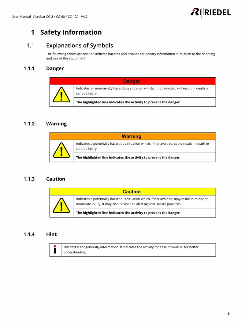
1.1 Explanations of Symbols The following tables are used to indicate hazards and provide cautionary information in relation to the handling and use of the equipment.
1.1.1 Danger
Danger Indicates an imminently hazardous situation which, if not avoided, will result in death or serious injury.
The highlighted line indicates the activity to prevent the danger.
1.1.2 Warning
Warning Indicates a potentially hazardous situation which, if not avoided, could result in death or serious injury.
The highlighted line indicates the activity to prevent the danger.
1.1.3 Caution
Caution Indicates a potentially hazardous situation which, if not avoided, may result in minor or moderate injury. It may also be used to alert against unsafe practices.
The highlighted line indicates the activity to prevent the danger.
1.1.4 Hint
This text is for generally information. It indicates the activity for ease of work or for better understanding.
User Manual Acrobat CC-8 / CC-60 / CC-120 V4.2
6
1.2 Service • All service has to be undertaken ONLY by qualified service personnel. • There are no user serviceable parts inside the device. • Never attempt to modify the equipment components for any reason.
Caution
All adjustments have been done at the factory before the shipment of the devices. No maintenance is required and no user serviceable parts are inside the module.
1.3 Voltage • Ensure that the supply voltage available at the installation site meets the voltage range of the equipment. • The power cable should only be connected to a correctly grounded source. • Do not use any adapters. • Never bypass a ground contact. • Only use the power cables provided with the equipment. • The power cord must be rated for the product and for the voltage and current marked on the product’s label. • When you remove a power cable never pull on the cable itself but on the connector. A damaged cable could
lead to shocks or burns. • Only use extension cords that are 3 poled and grounded. The power cables are equipped with 3 pole
connectors in order to minimize the risk of an electric shock.
Danger
Non-observance can lead to electrical shock. Do not open the chassis.
1.4 Environment • Never place the mainframe in an area of high dust particles or humidity. • Operating temperature of the system: -5°C – +50°C. • Never place containers with any liquids on top of the mainframe. • If the equipment has been exposed to a cold environment and transferred to a warm environment,
condensation may form inside the housing. Wait at least 6 hours before applying any power to the equipment.
User Manual Acrobat CC-8 / CC-60 / CC-120 V4.2
7
1.5 Battery Safety The device is fitted with the following battery: Lithium battery CR2032. Use only the original Lithium battery!
Warning Risk of explosion if battery is replaced by any other incorrect type. Do not short circuit. May explode it disposed in fire.
Dispose of used batteries according to the instructions. Do not expose to high storage temperatures above 60°C (140°F).
1.6 CE Declaration of Conformity
The Acrobat devices conform to the EU guideline 1999 / 5 / EEC as attested by the CE mark.
FCC ID: AY3-BSIP1US IC: 267AQ-BSIP1US
1.7 Disposal Disposal of old Electrical & Electric Equipment (Applicable throughout the European Union and other European countries with separate collection programs)
This symbol, found on your product or on its packaging, indicates that this product should not be treated as household waste when you wish to dispose of it. Instead, it should be handed over to an applicable collection point for the recycling of electrical and electronic equipment. By ensuring this product is disposed of correctly, you will help prevent potential negative consequences to the environment and human health, which could otherwise be caused by inappropriate disposal of this product. The recycling of materials will help to conserve natural resources. For more detailed information about the recycling of this product please contact your local city office.
User Manual Acrobat CC-8 / CC-60 / CC-120 V4.2
8
2 Introduction
2.1 General Thank you for choosing a Riedel product. This Manual describes the Installation, Configuration and Operation of the Riedel Acrobat CC-8 / CC-60 / CC-120 Digital Wireless Intercom system. For further information about the Acrobat hardware please contact your local distributor or the Riedel headquarters in Wuppertal.
2.2 Terminology • The term BSIP (Base Station IP) is used as a synonym for an Acrobat CA-6 Cell Antenna. • The term Beltpack and Wdpl are used as a synonym for an Acrobat WB-2 Wireless Beltpack. • The term IWU (InterWorking Unit), Acrobat CC or CC is used as a synonym for a Cell Controller (CC-8, CC-60
and CC-120). • The term Acrobat is used as a synonym for the whole Acrobat Digital Wireless Intercom system.
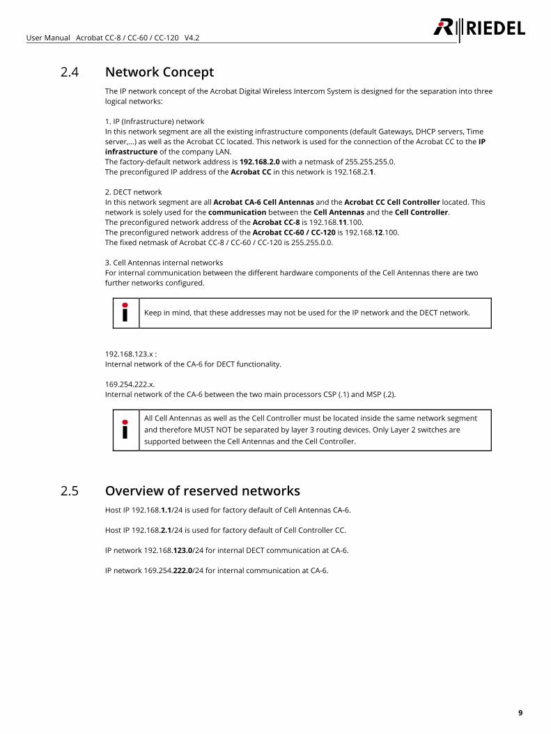
2.3 Document Scope This document describes all platforms of the Acrobat Digital Wireless Intercom system: • Acrobat CC-8 • Acrobat CC-60 • Acrobat CC-120 Feature comparison:
Product Max. WB-2 Max. CA-6 Remarks Acrobat CC-8 18 35 Built-in Audioboard, GPIO and 4 port PoE Switch
Acrobat CC-60 60 100
Acrobat CC-120 100 100
Unless otherwise noted, the instructions in this document refer to all three platforms.
User Manual Acrobat CC-8 / CC-60 / CC-120 V4.2
9
2.4 Network Concept The IP network concept of the Acrobat Digital Wireless Intercom System is designed for the separation into three logical networks: 1. IP (Infrastructure) network In this network segment are all the existing infrastructure components (default Gateways, DHCP servers, Time server,...) as well as the Acrobat CC located. This network is used for the connection of the Acrobat CC to the IP infrastructure of the company LAN. The factory-default network address is 192.168.2.0 with a netmask of 255.255.255.0. The preconfigured IP address of the Acrobat CC in this network is 192.168.2.1. 2. DECT network In this network segment are all Acrobat CA-6 Cell Antennas and the Acrobat CC Cell Controller located. This network is solely used for the communication between the Cell Antennas and the Cell Controller. The preconfigured network address of the Acrobat CC-8 is 192.168.11.100. The preconfigured network address of the Acrobat CC-60 / CC-120 is 192.168.12.100. The fixed netmask of Acrobat CC-8 / CC-60 / CC-120 is 255.255.0.0. 3. Cell Antennas internal networks For internal communication between the different hardware components of the Cell Antennas there are two further networks configured.
Keep in mind, that these addresses may not be used for the IP network and the DECT network.
192.168.123.x : Internal network of the CA-6 for DECT functionality. 169.254.222.x. Internal network of the CA-6 between the two main processors CSP (.1) and MSP (.2).
All Cell Antennas as well as the Cell Controller must be located inside the same network segment and therefore MUST NOT be separated by layer 3 routing devices. Only Layer 2 switches are supported between the Cell Antennas and the Cell Controller.
2.5 Overview of reserved networks Host IP 192.168.1.1/24 is used for factory default of Cell Antennas CA-6. Host IP 192.168.2.1/24 is used for factory default of Cell Controller CC. IP network 192.168.123.0/24 for internal DECT communication at CA-6. IP network 169.254.222.0/24 for internal communication at CA-6.
User Manual Acrobat CC-8 / CC-60 / CC-120 V4.2
10
2.6 Synchronization via Ethernet (acc. IEEE1588) Using synchronization via Ethernet, great demands are made on the Ethernet characteristics like symmetry, packet loss, delay, jitter (variance of delay), … Therefore special requirements regarding the Ethernet components (especially the Ethernet switches used) have to be considered. Exceeding of limits (especially of jitter) will lead to loss of synchronization, which will finally lead to a resynchronization process. During this process the belonging Cell Antennas are unable to establish an audio connection. Synchronization topology The Synchronization according Ethernet solely uses a star shaped topology. Maximally one Cell Antenna serves a Synchronization Master (Sync Master), all other Cell Antennas which participate at the synchronization serve as Synchronization Slaves (Sync Slave). Resynchronization The DECT functionality of all CA-6, which are configured as IEEE1588 Sync Slaves, depends on the availability of the IEEE1588 Sync Master. If the Sync Master is not functional (e. g not Online due to Ethernet problems), the DECT functionality of all IEEE1588 sync slave CA-6 will go down. During this time no audio connections are possible. General requirements on the Ethernet system The usage of a dedicated VLAN at the Cell Controller for Infrastructure and DECT network is mandatory. The CoS value of the DECT VLAN must be assigned to the highest priority in the network switch. All participating switches have to be configured in a way that the VLAN of the DECT network has to be assigned the highest priority. Further details regarding Ethernet Synchronization according IEEE1588 may be found in chapter “6.2 Ethernet Synchronization (acc. IEEE1588)” on page 93. Only premium class switches, which fulfill the requirements regarding Ethernet synchronization according IEEE1588, are supported. Following switches are already tested and can be used: • 24-port PoE Layer2 switch from D-Link; e.g. - DES-1228P, DES-3028P, DGS-1224TP • 24-port PoE Layer2 switch from Hewlett Packard (HP ProCurve Series), e.g. - 2626-PWR, 2650-PWR • Enterasys Switch B3G124 (1Gbit) • Enterasys Switch B5G124 • Cisco Catalyst 3560 • Cisco Catalyst 2960-48PST-L (48 PoE ports) • Cisco Small Business Pro ESW 500 (all switch ports used for CA-6 were configured as "others") • Cisco SG 300-28P • Cisco SG 500-28P Riedel gained unsuccessful experience with the following switch model: • Netgear FS1008 • Allnet
If the customer use Layer3 switches, the L3 function of the relevant switch ports have to be deactivated.
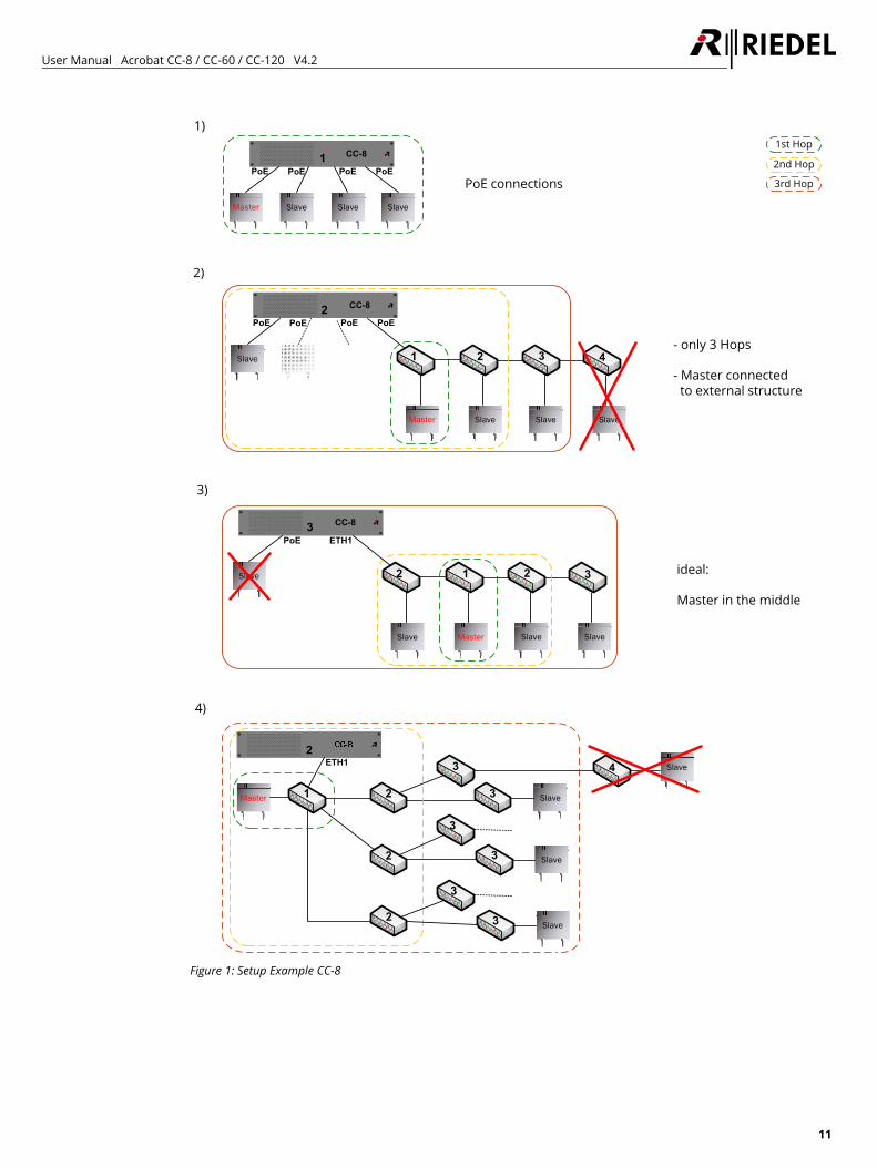
A maximum number of three cascaded Ethernet switches are supported between the Sync Master (SM) and a Sync Slave (SS) CA-6. Please notice that the CC-8 already contains one switch behind the PoE ports. Also this switch counts as a hop, if used. The graphics on the next pages illustrate different network setups limited by the three hops rule.
User Manual Acrobat CC-8 / CC-60 / CC-120 V4.2
11
Slave
3
1)
4)
Master Slave
CC-8
Slave Slave
1st Hop
2nd Hop
3rd Hop
1
Master Slave
Slave
1
2
2 3
4
2
2
3
Slave3
3
Slave3
3
Master
2)
Slave
SlaveSlave Slave
1 2 3 4
CC-82PoE PoE
Slave- only 3 Hops
- Master connected to external structure
PoE connections
Slave
3)
Slave
SlaveMaster
2 1 2
CC-83PoE ETH1
ideal:
Master in the middle
ETH1
PoE PoE
PoE PoE PoE PoE
Figure 1: Setup Example CC-8
User Manual Acrobat CC-8 / CC-60 / CC-120 V4.2
12
CC-60/120
CC-60/120
CC-60/120
Slave
3
1)
3)
1st Hop
2nd Hop
3rd Hop
Master Slave
Slave
1 2 3
4
2
2
3
Slave3
3
Slave3
3
Master SlaveSlave Slave
1 2 3 4 - only 3 Hops
- Master connected to external structure
Slave
2)
SlaveMaster
2 1 2 ideal:
Master in the middle
Configuration Port only
Configuration Port only
Configuration Port only
Gb 1 Gb 2
Gb 1 Gb 2
Gb 1 Gb 2
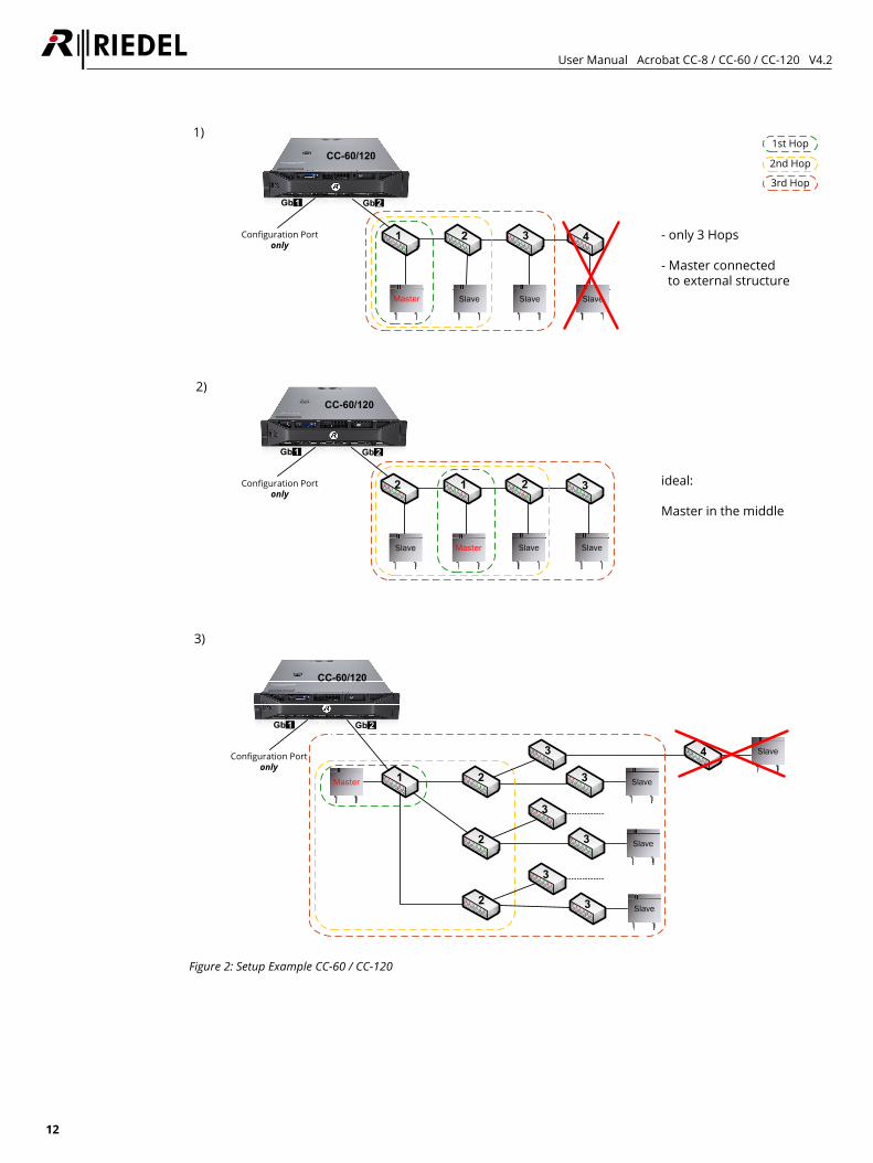
Figure 2: Setup Example CC-60 / CC-120
User Manual Acrobat CC-8 / CC-60 / CC-120 V4.2
13
2.7 WBM (Web Based Management) related issues 2.7.1 Supported Web Browser
Supported Web Browsers are: • Mozilla Firefox Versions 2.x … 10.x • Microsoft Internet Explorer Version 6.x … 8.x For details refer to chapter "8.1 Configuration hints for Web Browser“ on page 96.
2.7.2 General WBM issues • Valid values are 0-9, a-z, A-Z, "-", "_", "#", "*", "/", "(", ")", "<", ">". Other characters may prevent the system
services from running correctly. • Don’t configure names for objects with more than 20 Characters. • Changing of IP addresses of Cell Antenna - after changes have been applied, a manual [Sync] and [Scan] has to
be applied to show the new values • Configuration and firmware files must not include spaces in their filenames
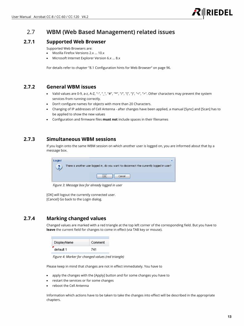
2.7.3 Simultaneous WBM sessions If you login onto the same WBM session on which another user is logged on, you are informed about that by a message box.
Figure 3: Message box for already logged in user
[OK] will logout the currently connected user. [Cancel] Go back to the Login dialog.
2.7.4 Marking changed values Changed values are marked with a red triangle at the top left corner of the corresponding field. But you have to leave the current field for changes to come in effect (via TAB key or mouse).
Figure 4: Marker for changed values (red triangle)
Please keep in mind that changes are not in effect immediately. You have to • apply the changes with the [Apply] button and for some changes you have to • restart the services or for some changes • reboot the Cell Antenna Information which actions have to be taken to take the changes into effect will be described in the appropriate chapters.
User Manual Acrobat CC-8 / CC-60 / CC-120 V4.2
14
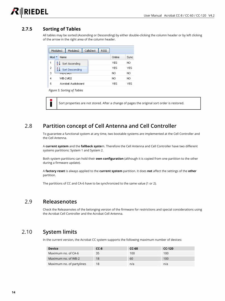
2.7.5 Sorting of Tables All tables may be sorted (Ascending or Descending) by either double-clicking the column header or by left clicking of the arrow in the right area of the column header.
Figure 5: Sorting of Tables
Sort properties are not stored. After a change of pages the original sort order is restored.
2.8 Partition concept of Cell Antenna and Cell Controller To guarantee a functional system at any time, two bootable systems are implemented at the Cell Controller and the Cell Antenna. A current system and the fallback system. Therefore the Cell Antenna and Cell Controller have two different systems partitions: System 1 and System 2. Both system partitions can hold their own configuration (although it is copied from one partition to the other during a firmware update). A factory reset is always applied to the current system partition. It does not affect the settings of the other partition. The partitions of CC and CA-6 have to be synchronized to the same value (1 or 2).
2.9 Releasenotes Check the Releasenotes of the belonging version of the firmware for restrictions and special considerations using the Acrobat Cell Controller and the Acrobat Cell Antenna.
2.10 System limits In the current version, the Acrobat CC system supports the following maximum number of devices:
Device CC-8 CC-60 CC-120 Maximum no. of CA-6 35 100 100
Maximum no. of WB-2 18 60 100
Maximum no. of partylines 18 n/a n/a
User Manual Acrobat CC-8 / CC-60 / CC-120 V4.2
15
3 User elements
3.1 ACROBAT CC-8 3.1.1 User Elements front
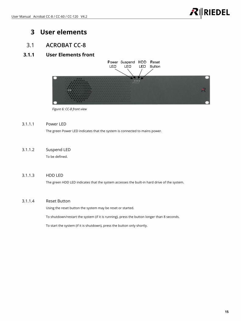
Figure 6: CC-8 front view
3.1.1.1 Power LED The green Power LED indicates that the system is connected to mains power.
3.1.1.2 Suspend LED To be defined.
3.1.1.3 HDD LED The green HDD LED indicates that the system accesses the built-in hard drive of the system.
3.1.1.4 Reset Button Using the reset button the system may be reset or started. To shutdown/restart the system (if it is running), press the button longer than 8 seconds. To start the system (if it is shutdown), press the button only shortly.
User Manual Acrobat CC-8 / CC-60 / CC-120 V4.2
16
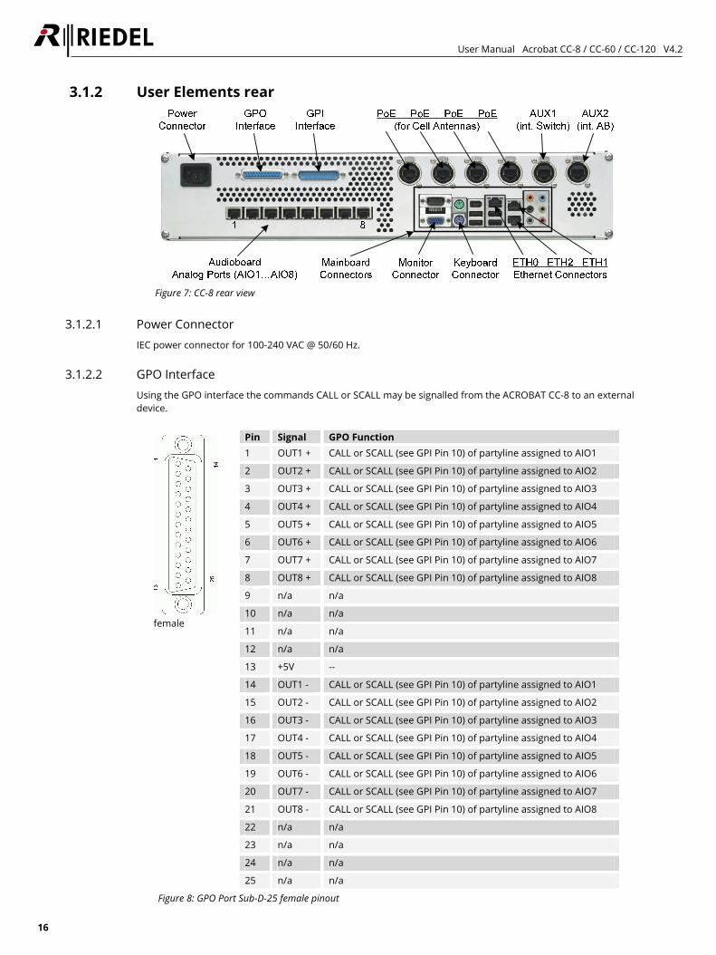
3.1.2 User Elements rear
Figure 7: CC-8 rear view
3.1.2.1 Power Connector IEC power connector for 100-240 VAC @ 50/60 Hz.
3.1.2.2 GPO Interface Using the GPO interface the commands CALL or SCALL may be signalled from the ACROBAT CC-8 to an external device.
female
Pin Signal GPO Function 1 OUT1 + CALL or SCALL (see GPI Pin 10) of partyline assigned to AIO1
2 OUT2 + CALL or SCALL (see GPI Pin 10) of partyline assigned to AIO2
3 OUT3 + CALL or SCALL (see GPI Pin 10) of partyline assigned to AIO3
4 OUT4 + CALL or SCALL (see GPI Pin 10) of partyline assigned to AIO4
5 OUT5 + CALL or SCALL (see GPI Pin 10) of partyline assigned to AIO5
6 OUT6 + CALL or SCALL (see GPI Pin 10) of partyline assigned to AIO6
7 OUT7 + CALL or SCALL (see GPI Pin 10) of partyline assigned to AIO7
8 OUT8 + CALL or SCALL (see GPI Pin 10) of partyline assigned to AIO8
9 n/a n/a
10 n/a n/a
11 n/a n/a
12 n/a n/a
13 +5V --
14 OUT1 - CALL or SCALL (see GPI Pin 10) of partyline assigned to AIO1
15 OUT2 - CALL or SCALL (see GPI Pin 10) of partyline assigned to AIO2
16 OUT3 - CALL or SCALL (see GPI Pin 10) of partyline assigned to AIO3
17 OUT4 - CALL or SCALL (see GPI Pin 10) of partyline assigned to AIO4
18 OUT5 - CALL or SCALL (see GPI Pin 10) of partyline assigned to AIO5
19 OUT6 - CALL or SCALL (see GPI Pin 10) of partyline assigned to AIO6
20 OUT7 - CALL or SCALL (see GPI Pin 10) of partyline assigned to AIO7
21 OUT8 - CALL or SCALL (see GPI Pin 10) of partyline assigned to AIO8
22 n/a n/a
23 n/a n/a
24 n/a n/a
25 n/a n/a
Figure 8: GPO Port Sub-D-25 female pinout
User Manual Acrobat CC-8 / CC-60 / CC-120 V4.2
17
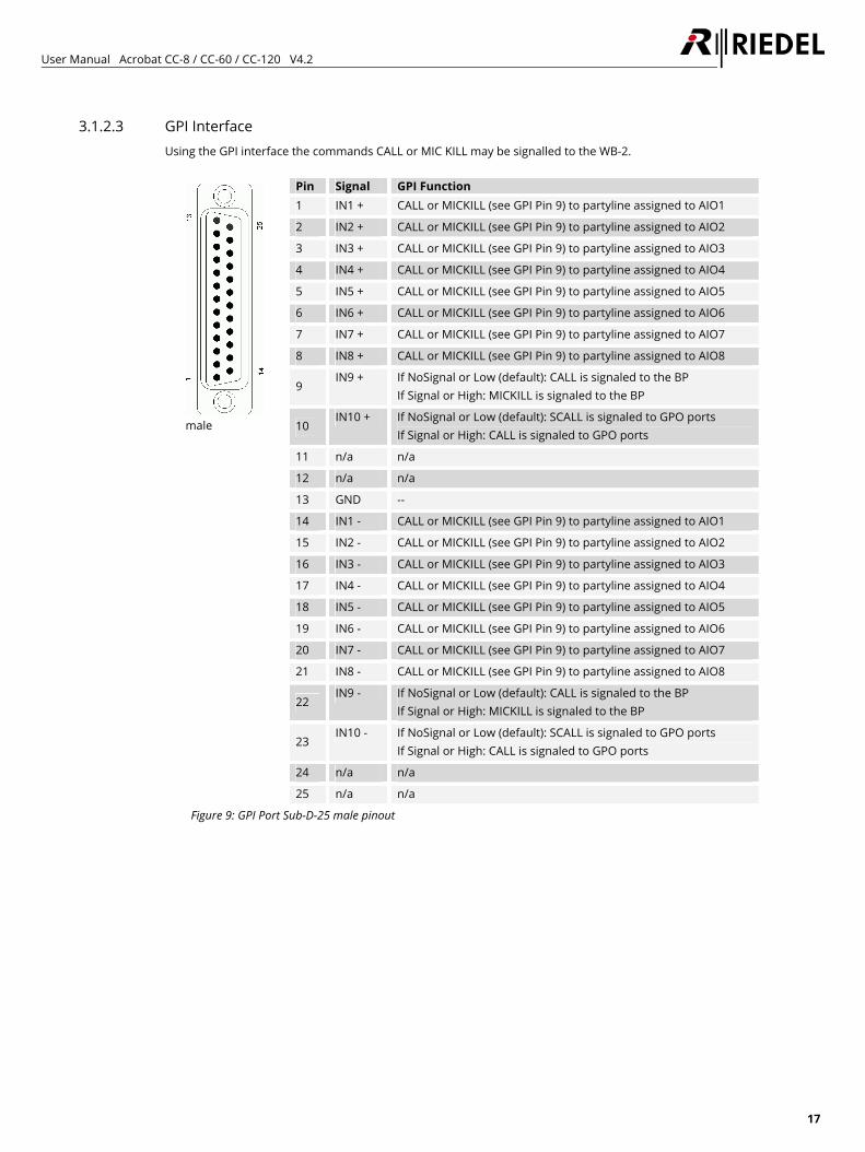
3.1.2.3 GPI Interface Using the GPI interface the commands CALL or MIC KILL may be signalled to the WB-2.
male
Pin Signal GPI Function 1 IN1 + CALL or MICKILL (see GPI Pin 9) to partyline assigned to AIO1
2 IN2 + CALL or MICKILL (see GPI Pin 9) to partyline assigned to AIO2
3 IN3 + CALL or MICKILL (see GPI Pin 9) to partyline assigned to AIO3
4 IN4 + CALL or MICKILL (see GPI Pin 9) to partyline assigned to AIO4
5 IN5 + CALL or MICKILL (see GPI Pin 9) to partyline assigned to AIO5
6 IN6 + CALL or MICKILL (see GPI Pin 9) to partyline assigned to AIO6
7 IN7 + CALL or MICKILL (see GPI Pin 9) to partyline assigned to AIO7
8 IN8 + CALL or MICKILL (see GPI Pin 9) to partyline assigned to AIO8
9 IN9 + If NoSignal or Low (default): CALL is signaled to the BP
If Signal or High: MICKILL is signaled to the BP
10 IN10 + If NoSignal or Low (default): SCALL is signaled to GPO ports
If Signal or High: CALL is signaled to GPO ports
11 n/a n/a
12 n/a n/a
13 GND --
14 IN1 - CALL or MICKILL (see GPI Pin 9) to partyline assigned to AIO1
15 IN2 - CALL or MICKILL (see GPI Pin 9) to partyline assigned to AIO2
16 IN3 - CALL or MICKILL (see GPI Pin 9) to partyline assigned to AIO3
17 IN4 - CALL or MICKILL (see GPI Pin 9) to partyline assigned to AIO4
18 IN5 - CALL or MICKILL (see GPI Pin 9) to partyline assigned to AIO5
19 IN6 - CALL or MICKILL (see GPI Pin 9) to partyline assigned to AIO6
20 IN7 - CALL or MICKILL (see GPI Pin 9) to partyline assigned to AIO7
21 IN8 - CALL or MICKILL (see GPI Pin 9) to partyline assigned to AIO8
22 IN9 - If NoSignal or Low (default): CALL is signaled to the BP
If Signal or High: MICKILL is signaled to the BP
23 IN10 - If NoSignal or Low (default): SCALL is signaled to GPO ports
If Signal or High: CALL is signaled to GPO ports
24 n/a n/a
25 n/a n/a
Figure 9: GPI Port Sub-D-25 male pinout
User Manual Acrobat CC-8 / CC-60 / CC-120 V4.2
18
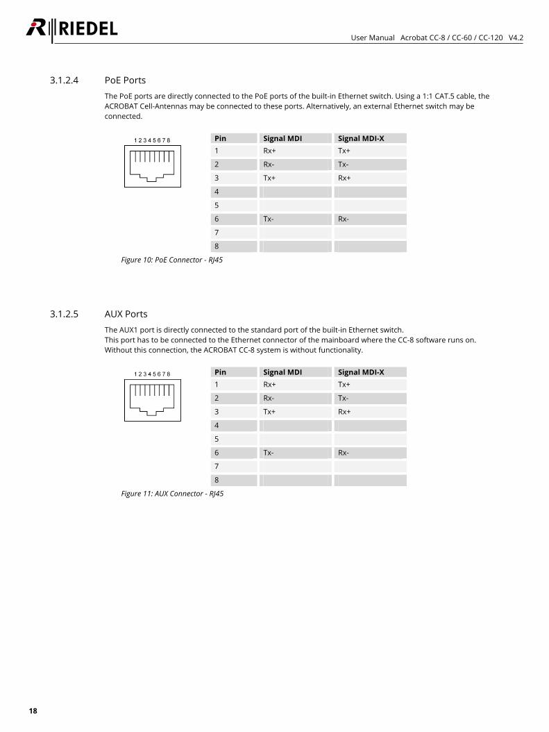
3.1.2.4 PoE Ports The PoE ports are directly connected to the PoE ports of the built-in Ethernet switch. Using a 1:1 CAT.5 cable, the ACROBAT Cell-Antennas may be connected to these ports. Alternatively, an external Ethernet switch may be connected.
Pin Signal MDI Signal MDI-X 1 Rx+ Tx+
2 Rx- Tx-
3 Tx+ Rx+
4
5
6 Tx- Rx-
7
8
Figure 10: PoE Connector - RJ45
3.1.2.5 AUX Ports The AUX1 port is directly connected to the standard port of the built-in Ethernet switch. This port has to be connected to the Ethernet connector of the mainboard where the CC-8 software runs on. Without this connection, the ACROBAT CC-8 system is without functionality.
Pin Signal MDI Signal MDI-X 1 Rx+ Tx+
2 Rx- Tx-
3 Tx+ Rx+
4
5
6 Tx- Rx-
7
8
Figure 11: AUX Connector - RJ45
User Manual Acrobat CC-8 / CC-60 / CC-120 V4.2
19
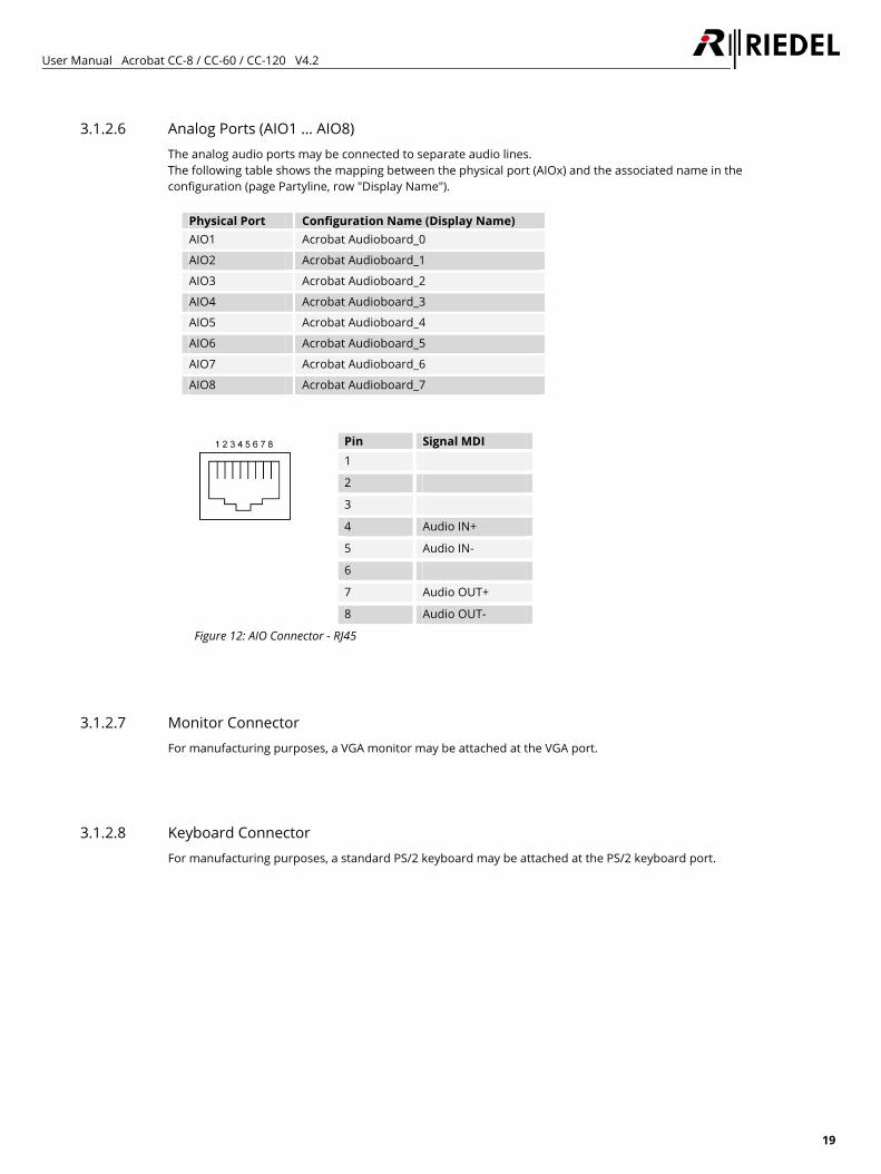
3.1.2.6 Analog Ports (AIO1 … AIO8) The analog audio ports may be connected to separate audio lines. The following table shows the mapping between the physical port (AIOx) and the associated name in the configuration (page Partyline, row "Display Name").
Physical Port Configuration Name (Display Name) AIO1 Acrobat Audioboard_0
AIO2 Acrobat Audioboard_1
AIO3 Acrobat Audioboard_2
AIO4 Acrobat Audioboard_3
AIO5 Acrobat Audioboard_4
AIO6 Acrobat Audioboard_5
AIO7 Acrobat Audioboard_6
AIO8 Acrobat Audioboard_7
Pin Signal MDI 1
2
3
4 Audio IN+
5 Audio IN-
6
7 Audio OUT+
8 Audio OUT-
Figure 12: AIO Connector - RJ45
3.1.2.7 Monitor Connector For manufacturing purposes, a VGA monitor may be attached at the VGA port.
3.1.2.8 Keyboard Connector For manufacturing purposes, a standard PS/2 keyboard may be attached at the PS/2 keyboard port.
User Manual Acrobat CC-8 / CC-60 / CC-120 V4.2
20
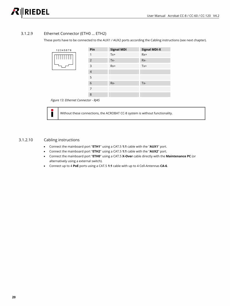
3.1.2.9 Ethernet Connector (ETH0 … ETH2) These ports have to be connected to the AUX1 / AUX2 ports according the Cabling instructions (see next chapter).
Pin Signal MDI Signal MDI-X 1 Tx+ Rx+
2 Tx- Rx-
3 Rx+ Tx+
4
5
6 Rx- Tx-
7
8
Figure 13: Ethernet Connector - RJ45
Without these connections, the ACROBAT CC-8 system is without functionality.
3.1.2.10 Cabling instructions • Connect the mainboard port "ETH1" using a CAT.5 1:1 cable with the "AUX1" port. • Connect the mainboard port "ETH2" using a CAT.5 1:1 cable with the "AUX2" port. • Connect the mainboard port "ETH0" using a CAT.5 X-Over cable directly with the Maintenance PC (or
alternatively using a external switch). • Connect up to 4 PoE ports using a CAT.5 1:1 cable with up to 4 Cell-Antennas CA-6.
User Manual Acrobat CC-8 / CC-60 / CC-120 V4.2
21
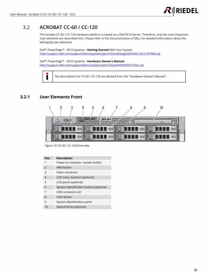
3.2 ACROBAT CC-60 / CC-120 The Acrobat CC-60 / CC-120 hardware platform is based on a Dell R510 Server. Therefore, only the most important User elements are described here. Please refer to the Documentation of DELL for detailed information about the belonging user elements. Dell™ PowerEdge™ - R510 Systems - Getting Started With Your System http://support.dell.com/support/edocs/systems/per510/multilang/GSG/DAO_BCC/3YPMN.zip Dell™ PowerEdge™ - R510 Systems - Hardware Owner’s Manual http://support.dell.com/support/edocs/systems/per510/en/HOM/PDF/510en.zip
The descriptions for CC-60 / CC-120 are derived from the "Hardware Owner’s Manual".
3.2.1 User Elements Front
Figure 14: CC-60 / CC-120 front view
Pos. Description 1 Power-on indicator / power button
2 NMI button
3 Video connector
4 LCD menu buttons (optional)
5 LCD panel (optional)
6 System identification button (optional)
7 USB connectors (2)
8 Hard drives
9 System identification panel
10 Optical drive (optional)
User Manual Acrobat CC-8 / CC-60 / CC-120 V4.2
22
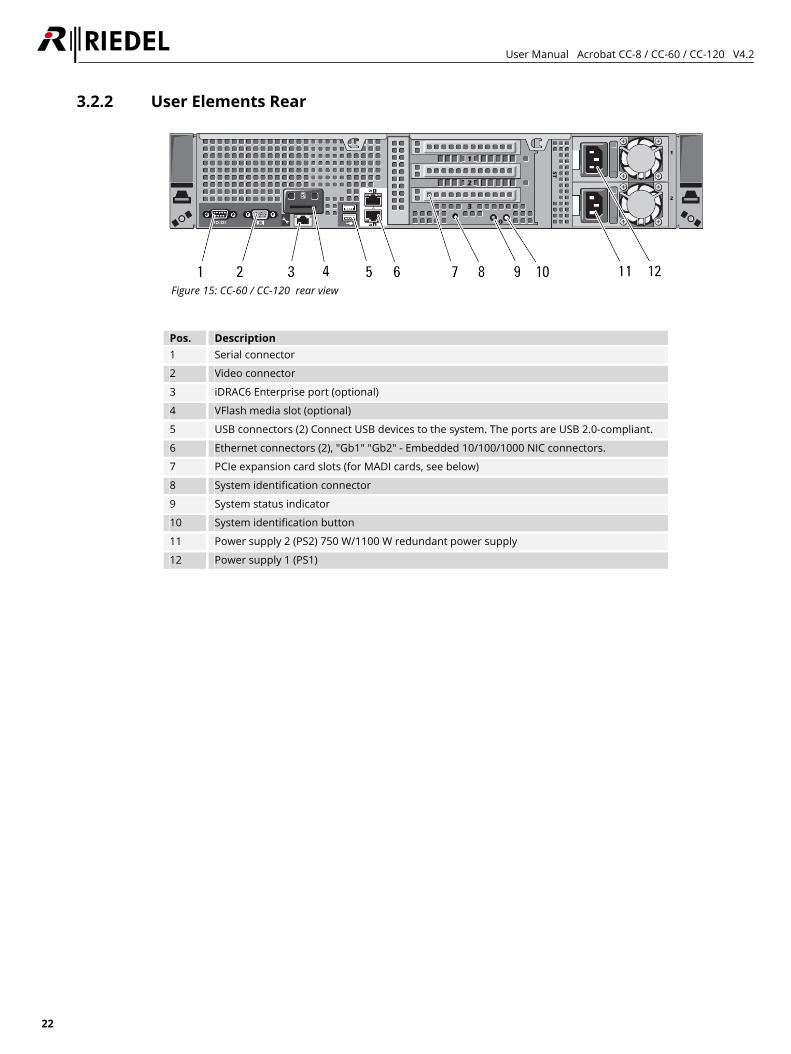
3.2.2 User Elements Rear
Figure 15: CC-60 / CC-120 rear view
Pos. Description 1 Serial connector
2 Video connector
3 iDRAC6 Enterprise port (optional)
4 VFlash media slot (optional)
5 USB connectors (2) Connect USB devices to the system. The ports are USB 2.0-compliant.
6 Ethernet connectors (2), "Gb1" "Gb2" - Embedded 10/100/1000 NIC connectors.
7 PCIe expansion card slots (for MADI cards, see below)
8 System identification connector
9 System status indicator
10 System identification button
11 Power supply 2 (PS2) 750 W/1100 W redundant power supply
12 Power supply 1 (PS1)
User Manual Acrobat CC-8 / CC-60 / CC-120 V4.2
23
3.2.3 Ethernet connectors "Gb1", "Gb2" (Pos. 6) These ports have to be connected to the maintenance PC and to a network switch according the Cabling instructions (see next chapter).
Without these connections, the ACROBAT CC-60 / 120 system is without functionality.
3.2.4 MADI boards (Pos. 7) The Acrobat CC-60 is equipped with one MADI card. This card has to be installed in PCIe expansion slot No. 2 (see figure above, Pos. "7"). The Acrobat CC-120 is equipped with two MADI cards. These cards have to be installed in PCIe expansion slots No. 1 and No. 2 (see figure above, Pos. "7").
3.2.5 Ethernet Cabling instructions The cabling depends on the configuration of the option "Switch ports" (refer to chapter 5.3.2 Network configuration on page 57). • Connect the "Gb1" port using a CAT.5 X-Over cable directly with the Maintenance PC (or alternatively using
1:1 cable to an external switch port which is assigned to the VLAN of the Infrastructure network). • Connect the "Gb2" port using a CAT.5 1:1 cable to an external switch port which is assigned to the VLAN of the
DECT network. For setup scenarios refer to Figure 2: Setup Example CC-60 / CC-120 on page 12. For detailed setup scenarios refer to the “Acrobat Installation and Planning Guide”.
3.2.6 MADI cabling instructions Connect the MADI connectors to the Artist system using appropriate fiber or Coax cables according your needs. Crossconnect the cables, e.g at Acrobat CC connect "Rx" to "Tx" side at Artist and vice versa. For detailed MADI setup scenarios refer to the “Acrobat Installation and Planning Guide”.
User Manual Acrobat CC-8 / CC-60 / CC-120 V4.2
24
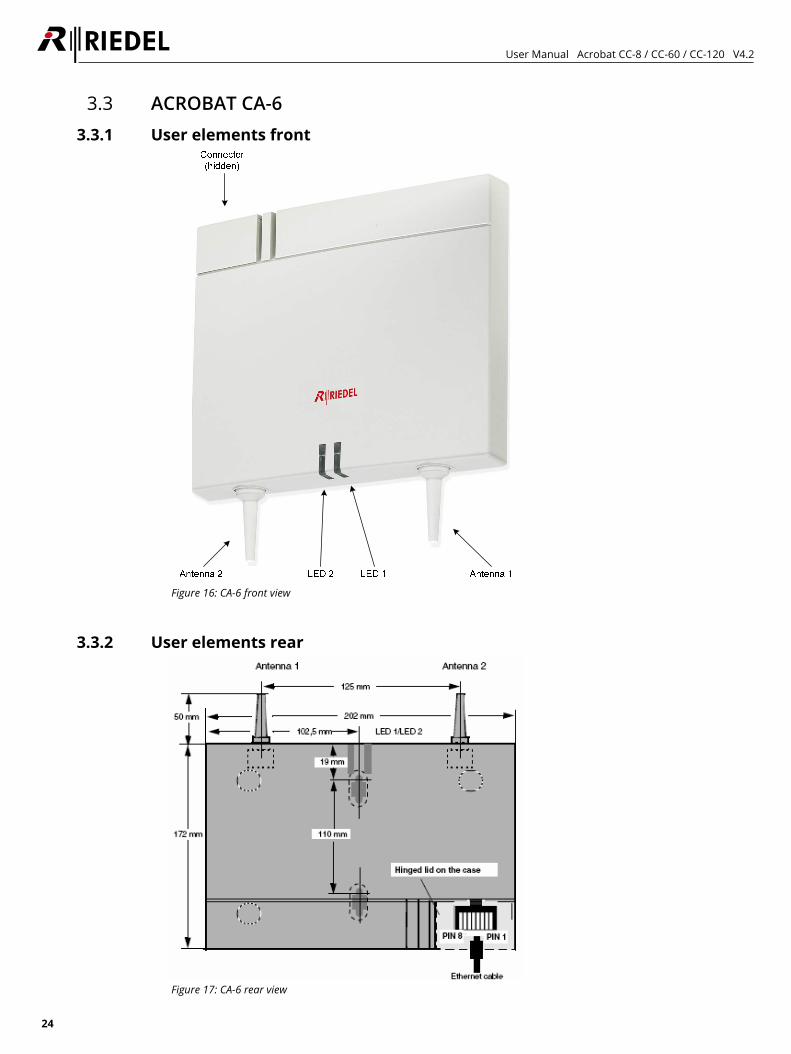
3.3 ACROBAT CA-6 3.3.1 User elements front
Figure 16: CA-6 front view
3.3.2 User elements rear
Figure 17: CA-6 rear view
User Manual Acrobat CC-8 / CC-60 / CC-120 V4.2
25
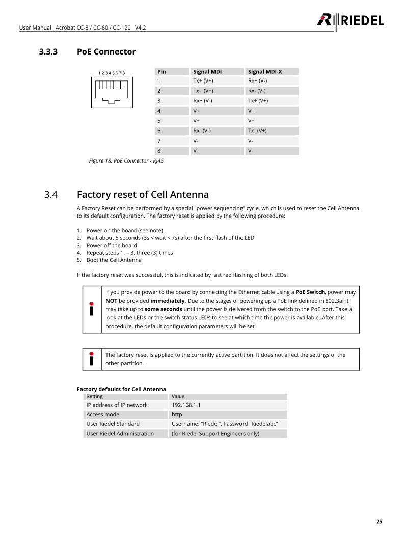
3.3.3 PoE Connector
Pin Signal MDI Signal MDI-X 1 Tx+ (V+) Rx+ (V-)
2 Tx- (V+) Rx- (V-)
3 Rx+ (V-) Tx+ (V+)
4 V+ V+
5 V+ V+
6 Rx- (V-) Tx- (V+)
7 V- V-
8 V- V-
Figure 18: PoE Connector - RJ45
3.4 Factory reset of Cell Antenna A Factory Reset can be performed by a special "power sequencing" cycle, which is used to reset the Cell Antenna to its default configuration. The factory reset is applied by the following procedure: 1. Power on the board (see note) 2. Wait about 5 seconds (3s < wait < 7s) after the first flash of the LED 3. Power off the board 4. Repeat steps 1. – 3. three (3) times 5. Boot the Cell Antenna If the factory reset was successful, this is indicated by fast red flashing of both LEDs.
If you provide power to the board by connecting the Ethernet cable using a PoE Switch, power may NOT be provided immediately. Due to the stages of powering up a PoE link defined in 802.3af it may take up to some seconds until the power is delivered from the switch to the PoE port. Take a look at the LEDs or the switch status LEDs to see at which time the power is available. After this procedure, the default configuration parameters will be set.
The factory reset is applied to the currently active partition. It does not affect the settings of the other partition.
Factory defaults for Cell Antenna
Setting Value
IP address of IP network 192.168.1.1
Access mode http
User Riedel Standard Username: "Riedel", Password "Riedelabc"
User Riedel Administration (for Riedel Support Engineers only)
User Manual Acrobat CC-8 / CC-60 / CC-120 V4.2
26
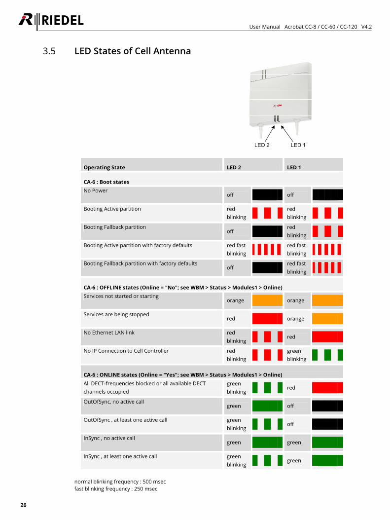
3.5 LED States of Cell Antenna
LED 1LED 2
Operating State LED 2 LED 1
CA-6 : Boot states No Power
off █████ off █████Booting Active partition red
blinking █ █ █ red blinking █ █ █
Booting Fallback partition off █████ red
blinking █ █ █Booting Active partition with factory defaults red fast
blinking ▌▌▌▌▌red fast blinking ▌▌▌▌▌
Booting Fallback partition with factory defaults off █████ red fast
blinking ▌▌▌▌▌
CA-6 : OFFLINE states (Online = "No"; see WBM > Status > Modules1 > Online) Services not started or starting
orange █████ orange █████Services are being stopped
red █████ orange █████No Ethernet LAN link red
blinking █ █ █ red █████No IP Connection to Cell Controller red
blinking █ █ █ green blinking █ █ █
CA-6 : ONLINE states (Online = "Yes"; see WBM > Status > Modules1 > Online) All DECT-frequencies blocked or all available DECT channels occupied
green blinking █ █ █ red █████
OutOfSync, no active call green █████ off █████
OutOfSync , at least one active call green blinking █ █ █ off █████
InSync , no active call green █████ green █████
InSync , at least one active call green blinking █ █ █ green █████
normal blinking frequency : 500 msec fast blinking frequency : 250 msec
User Manual Acrobat CC-8 / CC-60 / CC-120 V4.2
27
4 Quick Start Cell Controller (Example CC-8) The quick start chapter describes the initial operation of the Acrobat Digital Wireless Intercom system for a first functional test including the necessary configuration. The "Quick Start" assumes the availability of: • one Acrobat CC-8 Cell Controller, • two Acrobat CA-6 Cell Antennas, • two Acrobat WB-2 Wireless Beltpacks • a Maintenance PC (Windows XP based) with an administration account (if the ip configuration has to be
adapted) and • for each device connected a CAT.5 1:1 cable or 1 CAT.5 Cross-Over cable • a license file (voip-capi.lic) for the Acrobat Digital Wireless Intercom system which includes a unique DECT
SystemId (SystemAri) and the DECT frequency setting. Copy this file to the maintenance PC. • optionally, if using more components, a functional PoE network switch, (alternatively a standard switch and
Power injectors). Please read the corresponding chapter in the detailed manual parts if you need further information regarding any step of the "Quick Start". The following conditions apply for the Quick Start: • For the quick start it is assumed that no VLAN functionality is needed. • No special DECT functionality is configured (Antenna diversity,...). • It is assumed that a CC-8 - which is resetted to factory defaults - is used.
4.1 Quick start overview 1. Prepare and connect hardware 2. Configuration of Acrobat CC-8 Cell Controller 3. Configuration of IP (Infrastructure) network 4. Configuration of DECT network 5. Configuration of system services 6. Scan devices 7. Configuration of Audio board 8. Configuration of Acrobat CA-6 Cell Antennas 9. Configuration of Acrobat WB-2 Wireless Beltpacks 10. Configuration of Partylines (Beltpacks) 11. Configuration of Partylines (Audioboard users)
User Manual Acrobat CC-8 / CC-60 / CC-120 V4.2
28
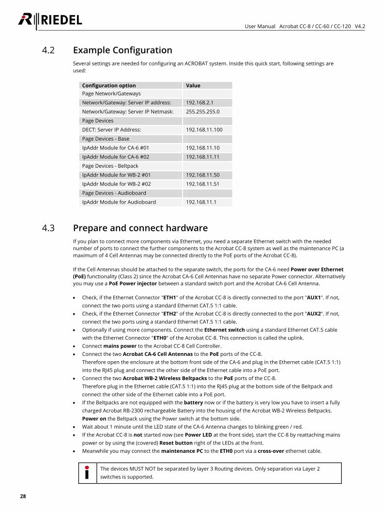
4.2 Example Configuration Several settings are needed for configuring an ACROBAT system. Inside this quick start, following settings are used:
Configuration option Value Page Network/Gateways
Network/Gateway: Server IP address: 192.168.2.1
Network/Gateway: Server IP Netmask: 255.255.255.0
Page Devices
DECT: Server IP Address: 192.168.11.100
Page Devices - Base
IpAddr Module for CA-6 #01 192.168.11.10
IpAddr Module for CA-6 #02 192.168.11.11
Page Devices - Beltpack
IpAddr Module for WB-2 #01 192.168.11.50
IpAddr Module for WB-2 #02 192.168.11.51
Page Devices - Audioboard
IpAddr Module for Audioboard 192.168.11.1
4.3 Prepare and connect hardware If you plan to connect more components via Ethernet, you need a separate Ethernet switch with the needed number of ports to connect the further components to the Acrobat CC-8 system as well as the maintenance PC (a maximum of 4 Cell Antennas may be connected directly to the PoE ports of the Acrobat CC-8). If the Cell Antennas should be attached to the separate switch, the ports for the CA-6 need Power over Ethernet (PoE) functionality (Class 2) since the Acrobat CA-6 Cell Antennas have no separate Power connector. Alternatively you may use a PoE Power injector between a standard switch port and the Acrobat CA-6 Cell Antenna. • Check, if the Ethernet Connector "ETH1" of the Acrobat CC-8 is directly connected to the port "AUX1". If not,
connect the two ports using a standard Ethernet CAT.5 1:1 cable. • Check, if the Ethernet Connector "ETH2" of the Acrobat CC-8 is directly connected to the port "AUX2". If not,
connect the two ports using a standard Ethernet CAT.5 1:1 cable. • Optionally if using more components. Connect the Ethernet switch using a standard Ethernet CAT.5 cable
with the Ethernet Connector "ETH0" of the Acrobat CC-8. This connection is called the uplink. • Connect mains power to the Acrobat CC-8 Cell Controller. • Connect the two Acrobat CA-6 Cell Antennas to the PoE ports of the CC-8.
Therefore open the enclosure at the bottom front side of the CA-6 and plug in the Ethernet cable (CAT.5 1:1) into the RJ45 plug and connect the other side of the Ethernet cable into a PoE port.
• Connect the two Acrobat WB-2 Wireless Beltpacks to the PoE ports of the CC-8. Therefore plug in the Ethernet cable (CAT.5 1:1) into the RJ45 plug at the bottom side of the Beltpack and connect the other side of the Ethernet cable into a PoE port.
• If the Beltpacks are not equipped with the battery now or if the battery is very low you have to insert a fully charged Acrobat RB-2300 rechargeable Battery into the housing of the Acrobat WB-2 Wireless Beltpacks. Power on the Beltpack using the Power switch at the bottom side.
• Wait about 1 minute until the LED state of the CA-6 Antenna changes to blinking green / red. • If the Acrobat CC-8 is not started now (see Power LED at the front side), start the CC-8 by reattaching mains
power or by using the (covered) Reset button right of the LEDs at the front. • Meanwhile you may connect the maintenance PC to the ETH0 port via a cross-over ethernet cable.
The devices MUST NOT be separated by layer 3 Routing devices. Only separation via Layer 2 switches is supported.
User Manual Acrobat CC-8 / CC-60 / CC-120 V4.2
29
4.4 Maintenance PC The Acrobat CC-8 is accessible via its factory default IP address 192.168.2.1. To access the web configuration interface you have to configure an IP address in the network 192.168.2.0/255.255.255.0, e.g. 192.168.2.101 on your maintenance PC.
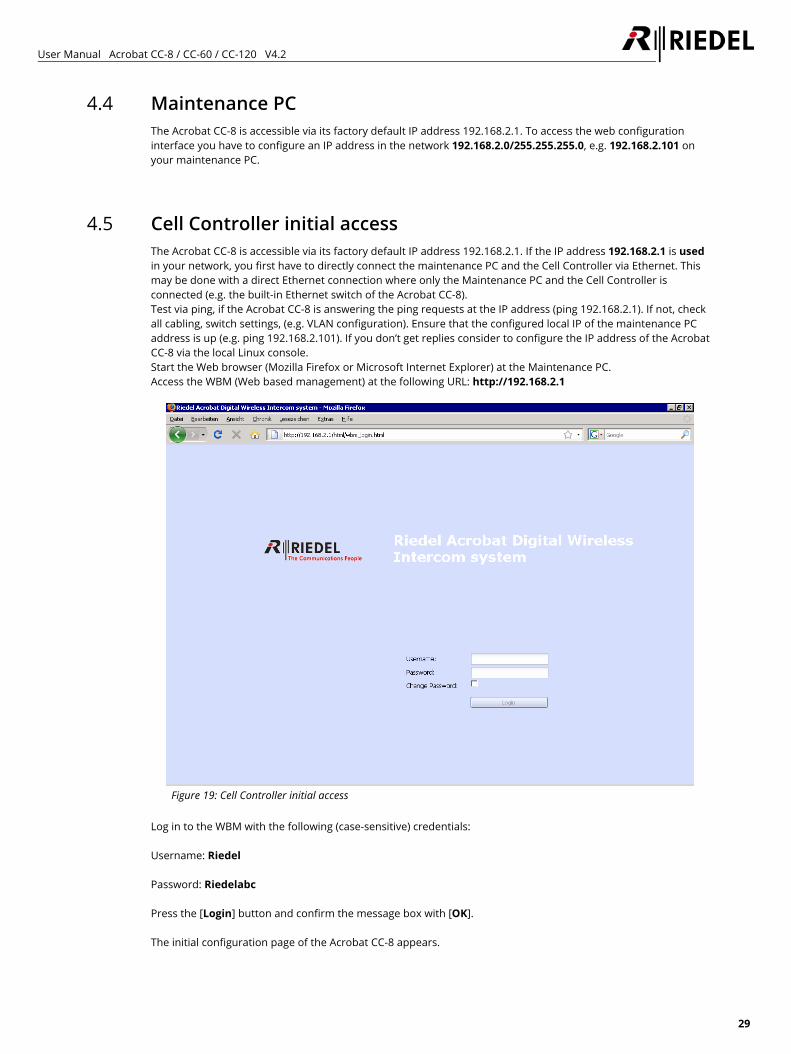
4.5 Cell Controller initial access The Acrobat CC-8 is accessible via its factory default IP address 192.168.2.1. If the IP address 192.168.2.1 is used in your network, you first have to directly connect the maintenance PC and the Cell Controller via Ethernet. This may be done with a direct Ethernet connection where only the Maintenance PC and the Cell Controller is connected (e.g. the built-in Ethernet switch of the Acrobat CC-8). Test via ping, if the Acrobat CC-8 is answering the ping requests at the IP address (ping 192.168.2.1). If not, check all cabling, switch settings, (e.g. VLAN configuration). Ensure that the configured local IP of the maintenance PC address is up (e.g. ping 192.168.2.101). If you don’t get replies consider to configure the IP address of the Acrobat CC-8 via the local Linux console. Start the Web browser (Mozilla Firefox or Microsoft Internet Explorer) at the Maintenance PC. Access the WBM (Web based management) at the following URL: http://192.168.2.1
Figure 19: Cell Controller initial access
Log in to the WBM with the following (case-sensitive) credentials: Username: Riedel Password: Riedelabc Press the [Login] button and confirm the message box with [OK]. The initial configuration page of the Acrobat CC-8 appears.
User Manual Acrobat CC-8 / CC-60 / CC-120 V4.2
30
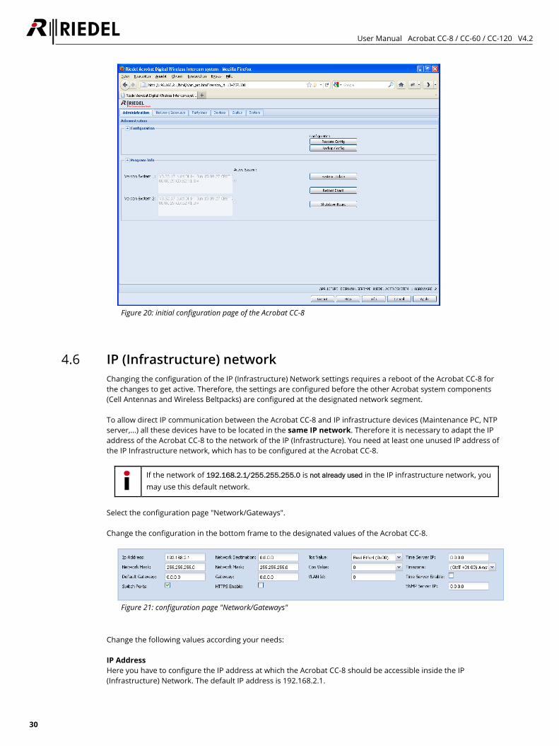
Figure 20: initial configuration page of the Acrobat CC-8
4.6 IP (Infrastructure) network Changing the configuration of the IP (Infrastructure) Network settings requires a reboot of the Acrobat CC-8 for the changes to get active. Therefore, the settings are configured before the other Acrobat system components (Cell Antennas and Wireless Beltpacks) are configured at the designated network segment. To allow direct IP communication between the Acrobat CC-8 and IP infrastructure devices (Maintenance PC, NTP server,...) all these devices have to be located in the same IP network. Therefore it is necessary to adapt the IP address of the Acrobat CC-8 to the network of the IP (Infrastructure). You need at least one unused IP address of the IP Infrastructure network, which has to be configured at the Acrobat CC-8.
If the network of 192.168.2.1/255.255.255.0 is not already used in the IP infrastructure network, you may use this default network.
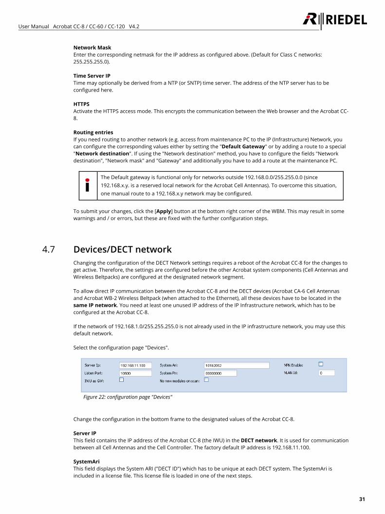
Select the configuration page "Network/Gateways". Change the configuration in the bottom frame to the designated values of the Acrobat CC-8.
Figure 21: configuration page "Network/Gateways"
Change the following values according your needs: IP Address Here you have to configure the IP address at which the Acrobat CC-8 should be accessible inside the IP (Infrastructure) Network. The default IP address is 192.168.2.1.
User Manual Acrobat CC-8 / CC-60 / CC-120 V4.2
31
Network Mask Enter the corresponding netmask for the IP address as configured above. (Default for Class C networks: 255.255.255.0). Time Server IP Time may optionally be derived from a NTP (or SNTP) time server. The address of the NTP server has to be configured here. HTTPS Activate the HTTPS access mode. This encrypts the communication between the Web browser and the Acrobat CC-8. Routing entries If you need routing to another network (e.g. access from maintenance PC to the IP (Infrastructure) Network, you can configure the corresponding values either by setting the "Default Gateway" or by adding a route to a special "Network destination". If using the "Network destination" method, you have to configure the fields "Network destination", "Network mask" and "Gateway" and additionally you have to add a route at the maintenance PC.
The Default gateway is functional only for networks outside 192.168.0.0/255.255.0.0 (since 192.168.x.y. is a reserved local network for the Acrobat Cell Antennas). To overcome this situation, one manual route to a 192.168.x.y network may be configured.
To submit your changes, click the [Apply] button at the bottom right corner of the WBM. This may result in some warnings and / or errors, but these are fixed with the further configuration steps.
4.7 Devices/DECT network Changing the configuration of the DECT Network settings requires a reboot of the Acrobat CC-8 for the changes to get active. Therefore, the settings are configured before the other Acrobat system components (Cell Antennas and Wireless Beltpacks) are configured at the designated network segment. To allow direct IP communication between the Acrobat CC-8 and the DECT devices (Acrobat CA-6 Cell Antennas and Acrobat WB-2 Wireless Beltpack (when attached to the Ethernet), all these devices have to be located in the same IP network. You need at least one unused IP address of the IP Infrastructure network, which has to be configured at the Acrobat CC-8. If the network of 192.168.1.0/255.255.255.0 is not already used in the IP infrastructure network, you may use this default network. Select the configuration page "Devices".
Figure 22: configuration page "Devices"
Change the configuration in the bottom frame to the designated values of the Acrobat CC-8. Server IP This field contains the IP address of the Acrobat CC-8 (the IWU) in the DECT network. It is used for communication between all Cell Antennas and the Cell Controller. The factory default IP address is 192.168.11.100. SystemAri This field displays the System ARI ("DECT ID") which has to be unique at each DECT system. The SystemAri is included in a license file. This license file is loaded in one of the next steps.
User Manual Acrobat CC-8 / CC-60 / CC-120 V4.2
32
IWU as GW Activate this option to use the Acrobat CC-8 as a router to the Cell Antennas.
Using the option "IWU as GW" enables the routing (IP forwarding) between the IP (Infrastructure) Network and the DECT Network. This ensures access to the network in which the Cell Antennas are located, without having an IP address (in the DECT network) configured at the maintenance PC. Additionally you have to add a route at the maintenance PC.
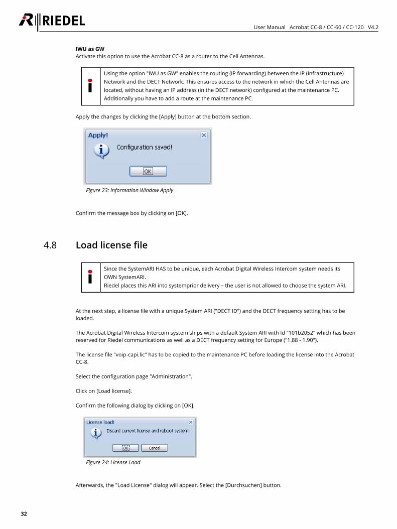
Apply the changes by clicking the [Apply] button at the bottom section.
Figure 23: Information Window Apply
Confirm the message box by clicking on [OK].
4.8 Load license file
Since the SystemARI HAS to be unique, each Acrobat Digital Wireless Intercom system needs its OWN SystemARI. Riedel places this ARI into systemprior delivery – the user is not allowed to choose the system ARI.
At the next step, a license file with a unique System ARI ("DECT ID") and the DECT frequency setting has to be loaded. The Acrobat Digital Wireless Intercom system ships with a default System ARI with Id "101b2052" which has been reserved for Riedel communications as well as a DECT frequency setting for Europe ("1.88 - 1.90"). The license file "voip-capi.lic" has to be copied to the maintenance PC before loading the license into the Acrobat CC-8. Select the configuration page "Administration". Click on [Load license]. Confirm the following dialog by clicking on [OK].
Figure 24: License Load
Afterwards, the "Load License" dialog will appear. Select the [Durchsuchen] button.
User Manual Acrobat CC-8 / CC-60 / CC-120 V4.2
33
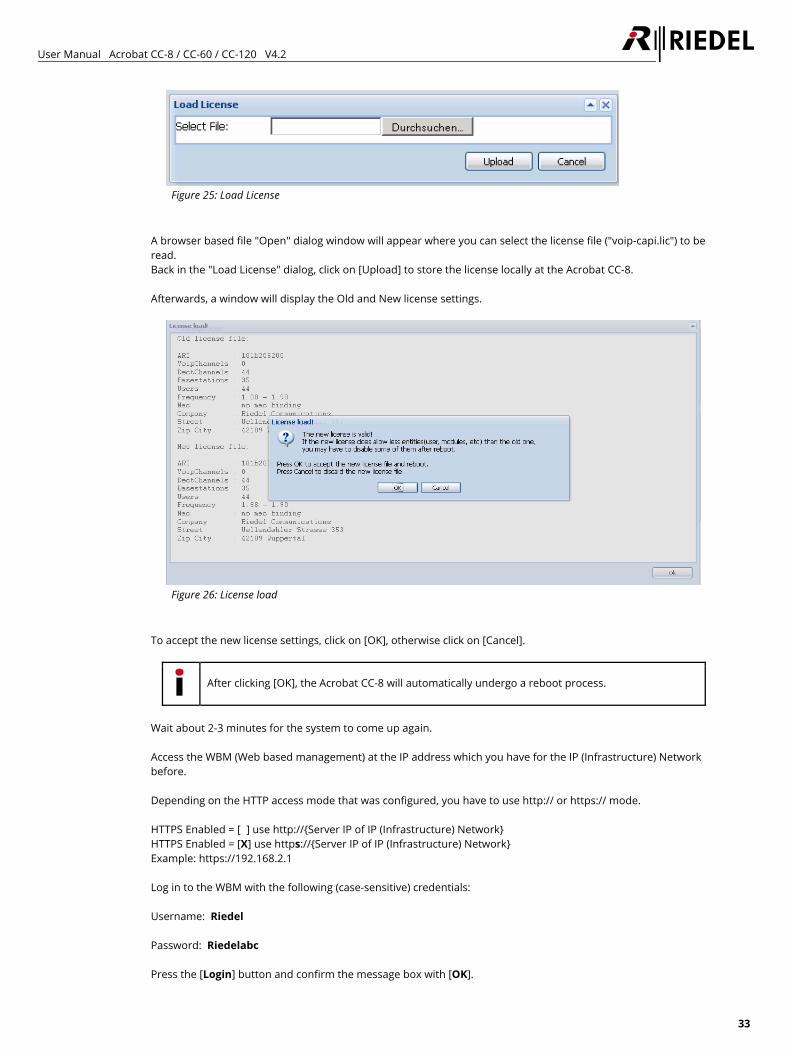
Figure 25: Load License
A browser based file "Open" dialog window will appear where you can select the license file ("voip-capi.lic") to be read. Back in the "Load License" dialog, click on [Upload] to store the license locally at the Acrobat CC-8. Afterwards, a window will display the Old and New license settings.
Figure 26: License load
To accept the new license settings, click on [OK], otherwise click on [Cancel].
After clicking [OK], the Acrobat CC-8 will automatically undergo a reboot process.
Wait about 2-3 minutes for the system to come up again. Access the WBM (Web based management) at the IP address which you have for the IP (Infrastructure) Network before. Depending on the HTTP access mode that was configured, you have to use http:// or https:// mode. HTTPS Enabled = [ ] use http://{Server IP of IP (Infrastructure) Network} HTTPS Enabled = [X] use https://{Server IP of IP (Infrastructure) Network} Example: https://192.168.2.1 Log in to the WBM with the following (case-sensitive) credentials: Username: Riedel Password: Riedelabc Press the [Login] button and confirm the message box with [OK].
User Manual Acrobat CC-8 / CC-60 / CC-120 V4.2
34
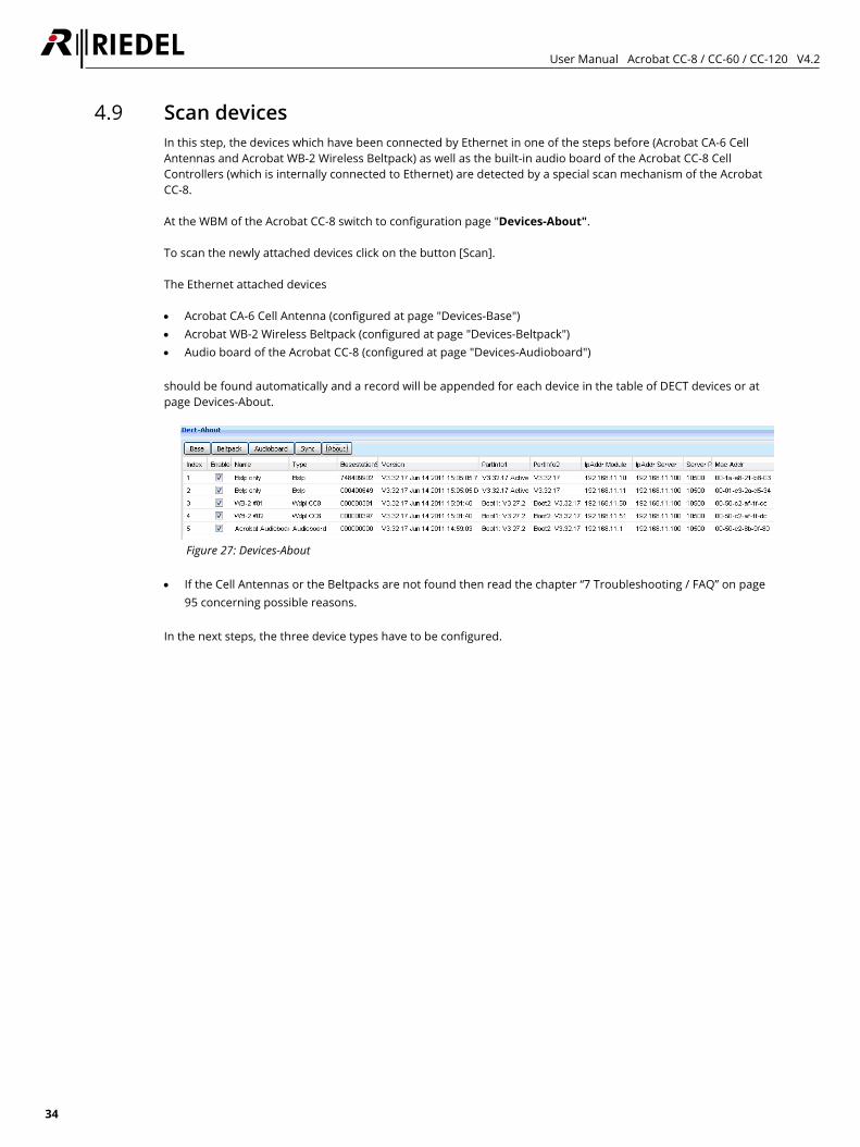
4.9 Scan devices In this step, the devices which have been connected by Ethernet in one of the steps before (Acrobat CA-6 Cell Antennas and Acrobat WB-2 Wireless Beltpack) as well as the built-in audio board of the Acrobat CC-8 Cell Controllers (which is internally connected to Ethernet) are detected by a special scan mechanism of the Acrobat CC-8. At the WBM of the Acrobat CC-8 switch to configuration page "Devices-About". To scan the newly attached devices click on the button [Scan]. The Ethernet attached devices • Acrobat CA-6 Cell Antenna (configured at page "Devices-Base") • Acrobat WB-2 Wireless Beltpack (configured at page "Devices-Beltpack") • Audio board of the Acrobat CC-8 (configured at page "Devices-Audioboard") should be found automatically and a record will be appended for each device in the table of DECT devices or at page Devices-About.
Figure 27: Devices-About
• If the Cell Antennas or the Beltpacks are not found then read the chapter “7 Troubleshooting / FAQ” on page
95 concerning possible reasons. In the next steps, the three device types have to be configured.
User Manual Acrobat CC-8 / CC-60 / CC-120 V4.2
35
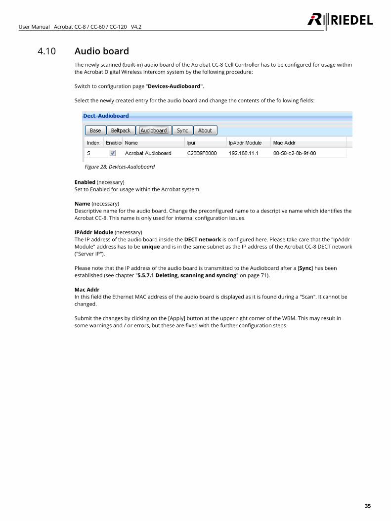
4.10 Audio board The newly scanned (built-in) audio board of the Acrobat CC-8 Cell Controller has to be configured for usage within the Acrobat Digital Wireless Intercom system by the following procedure: Switch to configuration page "Devices-Audioboard". Select the newly created entry for the audio board and change the contents of the following fields:
Figure 28: Devices-Audioboard
Enabled (necessary) Set to Enabled for usage within the Acrobat system. Name (necessary) Descriptive name for the audio board. Change the preconfigured name to a descriptive name which identifies the Acrobat CC-8. This name is only used for internal configuration issues. IPAddr Module (necessary) The IP address of the audio board inside the DECT network is configured here. Please take care that the "IpAddr Module" address has to be unique and is in the same subnet as the IP address of the Acrobat CC-8 DECT network ("Server IP"). Please note that the IP address of the audio board is transmitted to the Audioboard after a [Sync] has been established (see chapter "5.5.7.1 Deleting, scanning and syncing" on page 71). Mac Addr In this field the Ethernet MAC address of the audio board is displayed as it is found during a "Scan". It cannot be changed. Submit the changes by clicking on the [Apply] button at the upper right corner of the WBM. This may result in some warnings and / or errors, but these are fixed with the further configuration steps.
User Manual Acrobat CC-8 / CC-60 / CC-120 V4.2
36
4.11 Acrobat Cell Antenna 4.11.1 General
The newly scanned Cell Antennas have to be configured for usage within the Acrobat Digital Wireless Intercom system. If the Cell Antennas are not found please read the chapter "7 Troubleshooting / FAQ" on page 95 concerning possible reasons.
It is assumed that the first Cell Antenna is the synchronization master for the Over-Air synchronization of the second Cell Antenna.
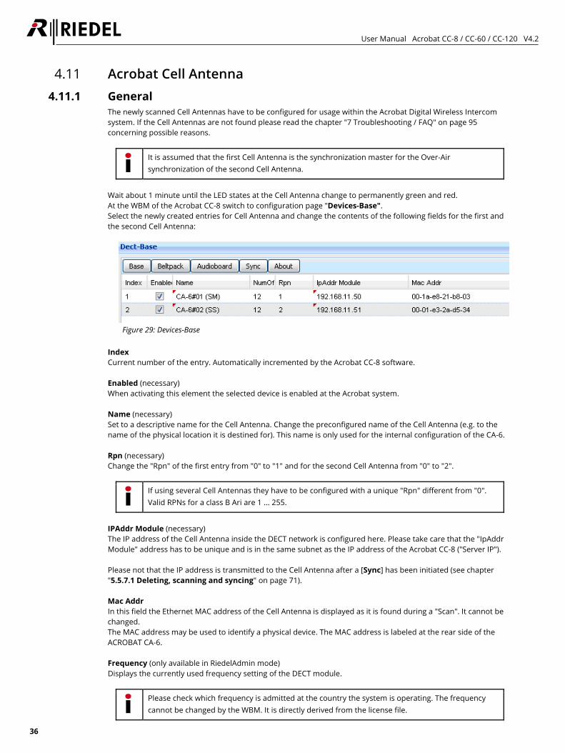
Wait about 1 minute until the LED states at the Cell Antenna change to permanently green and red. At the WBM of the Acrobat CC-8 switch to configuration page "Devices-Base". Select the newly created entries for Cell Antenna and change the contents of the following fields for the first and the second Cell Antenna:
Figure 29: Devices-Base
Index Current number of the entry. Automatically incremented by the Acrobat CC-8 software. Enabled (necessary) When activating this element the selected device is enabled at the Acrobat system. Name (necessary) Set to a descriptive name for the Cell Antenna. Change the preconfigured name of the Cell Antenna (e.g. to the name of the physical location it is destined for). This name is only used for the internal configuration of the CA-6. Rpn (necessary) Change the "Rpn" of the first entry from "0" to "1" and for the second Cell Antenna from "0" to "2".
If using several Cell Antennas they have to be configured with a unique "Rpn" different from "0". Valid RPNs for a class B Ari are 1 ... 255.
IPAddr Module (necessary) The IP address of the Cell Antenna inside the DECT network is configured here. Please take care that the "IpAddr Module" address has to be unique and is in the same subnet as the IP address of the Acrobat CC-8 ("Server IP"). Please not that the IP address is transmitted to the Cell Antenna after a [Sync] has been initiated (see chapter "5.5.7.1 Deleting, scanning and syncing" on page 71). Mac Addr In this field the Ethernet MAC address of the Cell Antenna is displayed as it is found during a "Scan". It cannot be changed. The MAC address may be used to identify a physical device. The MAC address is labeled at the rear side of the ACROBAT CA-6. Frequency (only available in RiedelAdmin mode) Displays the currently used frequency setting of the DECT module.
Please check which frequency is admitted at the country the system is operating. The frequency cannot be changed by the WBM. It is directly derived from the license file.
User Manual Acrobat CC-8 / CC-60 / CC-120 V4.2
37
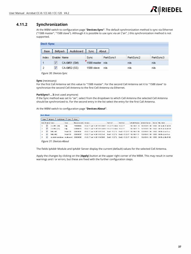
4.11.2 Synchronization At the WBM switch to configuration page "Devices-Sync". The default synchronization method is sync via Ethernet ("1588 master", "1588 slave"). Although it is possible to use sync via air ("air", ) this synchronization method is not supported.
Figure 30: Devices-Sync
Sync (necessary) For the first Cell Antenna set this value to "1588 master". For the second Cell Antenna set it to "1588 slave" to synchronize the second Cell Antenna to the first Cell Antenna via Ethernet. ParkSync1 .. 3 (not used anymore) If the Sync method was set to "air", select from the dropdown to which Cell Antenna the selected Cell Antenna should be synchronized to. For the second entry in the list select the entry for the first Call Antenna. At the WBM switch to configuration page "Devices-About".
Figure 31: Devices-About
The fields IpAddr Module and IpAddr Server display the current (default) values for the selected Cell Antenna. Apply the changes by clicking on the [Apply] button at the upper right corner of the WBM. This may result in some warnings and / or errors, but these are fixed with the further configuration steps.
User Manual Acrobat CC-8 / CC-60 / CC-120 V4.2
38
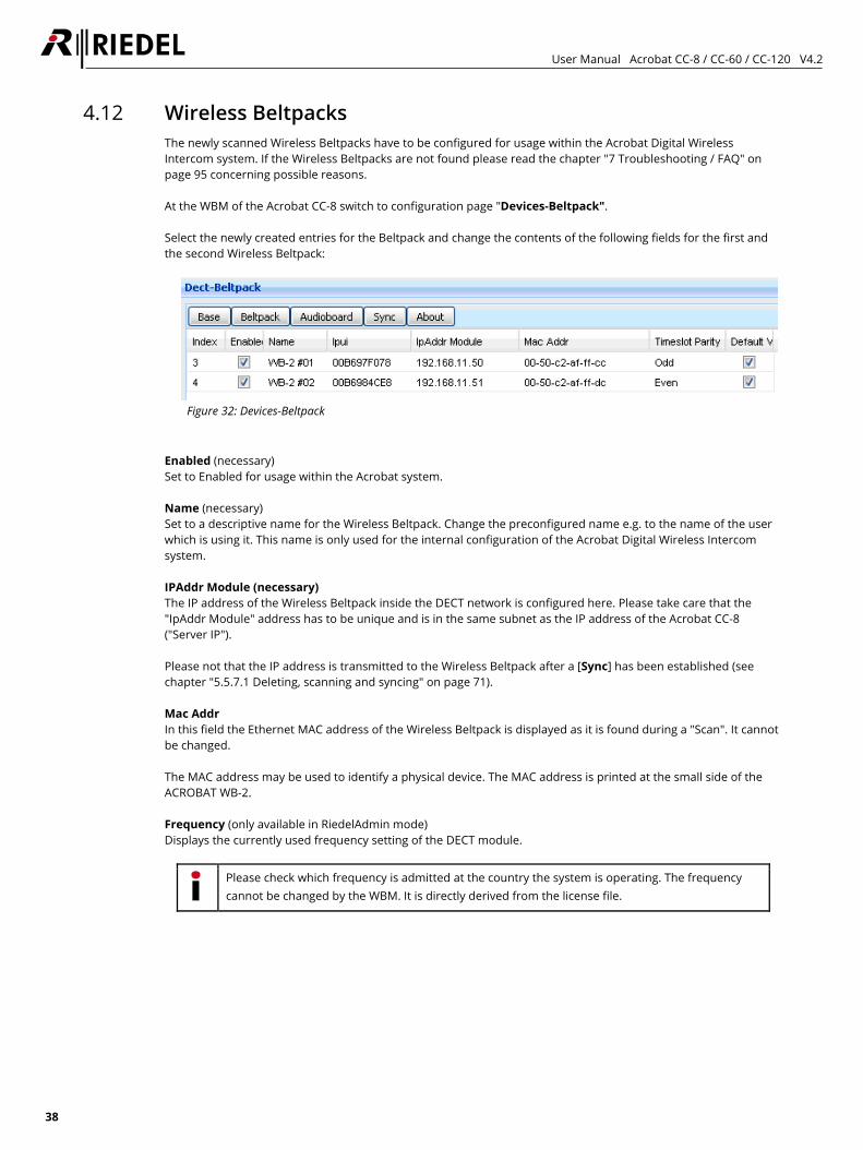
4.12 Wireless Beltpacks The newly scanned Wireless Beltpacks have to be configured for usage within the Acrobat Digital Wireless Intercom system. If the Wireless Beltpacks are not found please read the chapter "7 Troubleshooting / FAQ" on page 95 concerning possible reasons. At the WBM of the Acrobat CC-8 switch to configuration page "Devices-Beltpack". Select the newly created entries for the Beltpack and change the contents of the following fields for the first and the second Wireless Beltpack:
Figure 32: Devices-Beltpack
Enabled (necessary) Set to Enabled for usage within the Acrobat system. Name (necessary) Set to a descriptive name for the Wireless Beltpack. Change the preconfigured name e.g. to the name of the user which is using it. This name is only used for the internal configuration of the Acrobat Digital Wireless Intercom system. IPAddr Module (necessary) The IP address of the Wireless Beltpack inside the DECT network is configured here. Please take care that the "IpAddr Module" address has to be unique and is in the same subnet as the IP address of the Acrobat CC-8 ("Server IP"). Please not that the IP address is transmitted to the Wireless Beltpack after a [Sync] has been established (see chapter "5.5.7.1 Deleting, scanning and syncing" on page 71). Mac Addr In this field the Ethernet MAC address of the Wireless Beltpack is displayed as it is found during a "Scan". It cannot be changed. The MAC address may be used to identify a physical device. The MAC address is printed at the small side of the ACROBAT WB-2. Frequency (only available in RiedelAdmin mode) Displays the currently used frequency setting of the DECT module.
Please check which frequency is admitted at the country the system is operating. The frequency cannot be changed by the WBM. It is directly derived from the license file.
User Manual Acrobat CC-8 / CC-60 / CC-120 V4.2
39
CTR6 This option is needed for special testing option used with US frequencies. The default setting is disabled. Leave this option disabled. Timeslot Parity This value determines, if the corresponding Beltpack is working with odd or even DECT timeslots. To achieve good efficiency of the available DECT timeslots, configure half of the configured Beltpacks to use even timeslots, the other half to use odd timeslots. Regardless of this setting (even or odd), all WB-2 are able to communicate among each other if they are assigned to the same partyline. Default value Some settings of the WB-2 may only be changed locally at the WB-2 service menu. To reset these settings to default values, this option has to be Enabled.
The corresponding WB-2 has to be attached to the Ethernet for the settings to become active.
For details of default values, refer to the corresponding section at the User Manual of the WB-2. Apply the changes by clicking on the [Apply] button at the upper right corner of the WBM. This may result in some warnings and / or errors, but these are fixed with the further configuration steps. To submit all the changes to the Wireless Beltpack, the changes have to be transmitted to the devices. This process is established using the [Sync] button. During the synchronization process, the Wireless Beltpacks will receive their configuration values from the Cell Controller. Confirm the message box by clicking on [OK]. The following process will transfer the new settings to the Wireless Beltpack. Therefore, the Wireless Beltpacks will be rebooted automatically by the Acrobat CC-8. Wait about 1 minute until the Wireless Beltpacks are started completely.
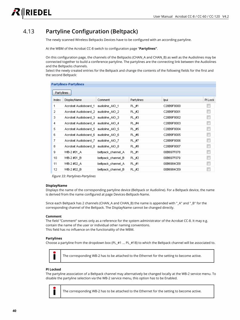
User Manual Acrobat CC-8 / CC-60 / CC-120 V4.2
40
4.13 Partyline Configuration (Beltpack) The newly scanned Wireless Beltpacks Devices have to be configured with an according partyline. At the WBM of the Acrobat CC-8 switch to configuration page "Partylines". On this configuration page, the channels of the Beltpacks (CHAN_A and CHAN_B) as well as the Audiolines may be connected together to build a conference partyline. The partylines are the connecting link between the Audiolines and the Beltpacks channels. Select the newly created entries for the Beltpack and change the contents of the following fields for the first and the second Beltpack:
Figure 33: Partylines-Partylines
DisplayName Displays the name of the corresponding partyline device (Beltpack or Audioline). For a Beltpack device, the name is derived from the name configured at page Devices-Beltpack-Name. Since each Beltpack has 2 channels (CHAN_A and CHAN_B) the name is appended with "_A" and "_B" for the corresponding channel of the Beltpack. The DisplayName cannot be changed directly. Comment The field "Comment" serves only as a reference for the system administrator of the Acrobat CC-8. It may e.g. contain the name of the user or individual other naming conventions. This field has no influence on the functionality of the WBM. Partylines Choose a partyline from the dropdown box (PL_#1 ... PL_#18) to which the Beltpack channel will be associated to.
The corresponding WB-2 has to be attached to the Ethernet for the setting to become active.
Pl Locked The partyline association of a Beltpack channel may alternatively be changed locally at the WB-2 service menu. To disable the partyline selection via the WB-2 service menu, this option has to be Enabled.
The corresponding WB-2 has to be attached to the Ethernet for the setting to become active.
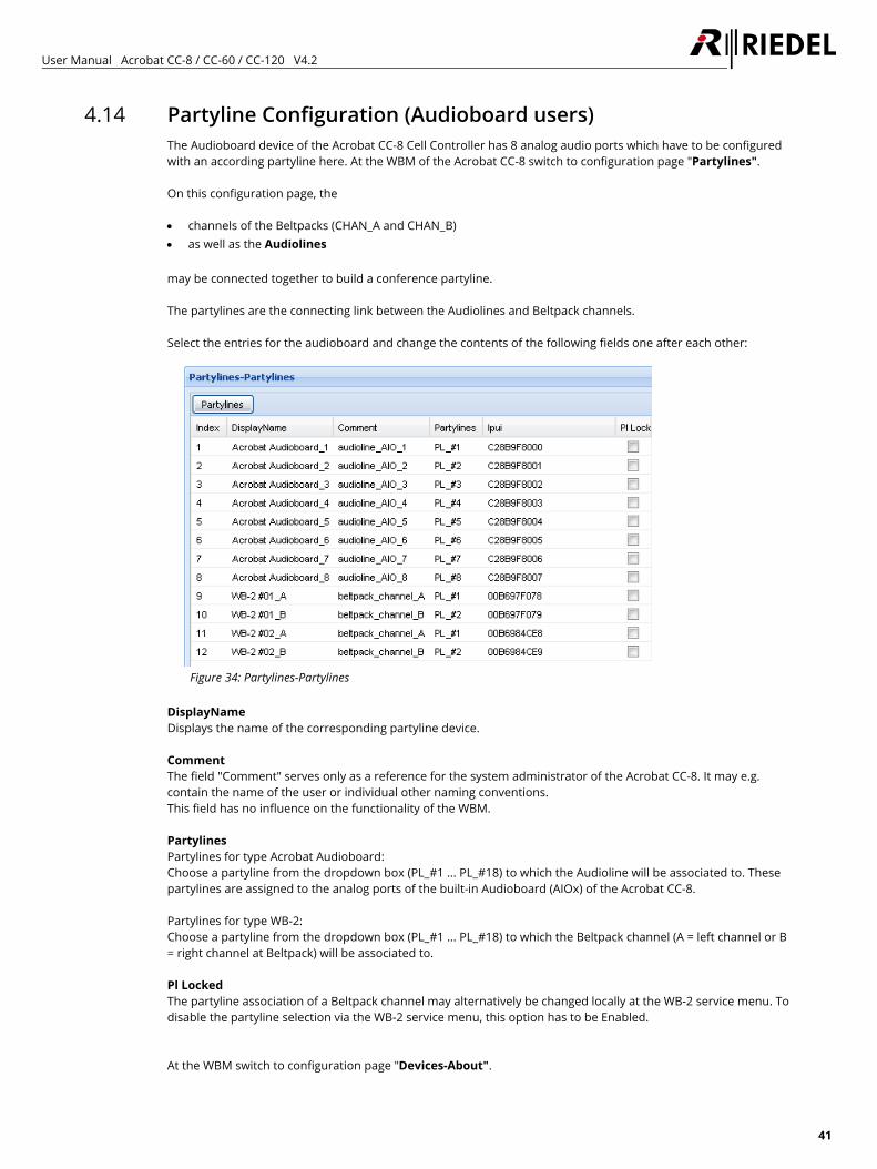
User Manual Acrobat CC-8 / CC-60 / CC-120 V4.2
41
4.14 Partyline Configuration (Audioboard users) The Audioboard device of the Acrobat CC-8 Cell Controller has 8 analog audio ports which have to be configured with an according partyline here. At the WBM of the Acrobat CC-8 switch to configuration page "Partylines". On this configuration page, the • channels of the Beltpacks (CHAN_A and CHAN_B) • as well as the Audiolines may be connected together to build a conference partyline. The partylines are the connecting link between the Audiolines and Beltpack channels. Select the entries for the audioboard and change the contents of the following fields one after each other:
Figure 34: Partylines-Partylines
DisplayName Displays the name of the corresponding partyline device. Comment The field "Comment" serves only as a reference for the system administrator of the Acrobat CC-8. It may e.g. contain the name of the user or individual other naming conventions. This field has no influence on the functionality of the WBM. Partylines Partylines for type Acrobat Audioboard: Choose a partyline from the dropdown box (PL_#1 ... PL_#18) to which the Audioline will be associated to. These partylines are assigned to the analog ports of the built-in Audioboard (AIOx) of the Acrobat CC-8. Partylines for type WB-2: Choose a partyline from the dropdown box (PL_#1 ... PL_#18) to which the Beltpack channel (A = left channel or B = right channel at Beltpack) will be associated to. Pl Locked The partyline association of a Beltpack channel may alternatively be changed locally at the WB-2 service menu. To disable the partyline selection via the WB-2 service menu, this option has to be Enabled. At the WBM switch to configuration page "Devices-About".
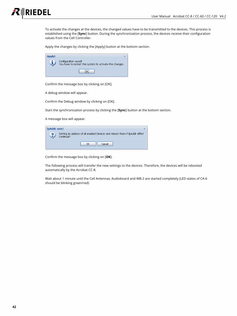
User Manual Acrobat CC-8 / CC-60 / CC-120 V4.2
42
To activate the changes at the devices, the changed values have to be transmitted to the devices. This process is established using the [Sync] button. During the synchronization process, the devices receive their configuration values from the Cell Controller. Apply the changes by clicking the [Apply] button at the bottom section.
Confirm the message box by clicking on [OK]. A debug window will appear. Confirm the Debug window by clicking on [OK]. Start the synchronization process by clicking the [Sync] button at the bottom section. A message box will appear.
Confirm the message box by clicking on [OK]. The following process will transfer the new settings to the devices. Therefore, the devices will be rebooted automatically by the Acrobat CC-8. Wait about 1 minute until the Cell Antennas, Audioboard and WB-2 are started completely (LED states of CA-6 should be blinking green/red)
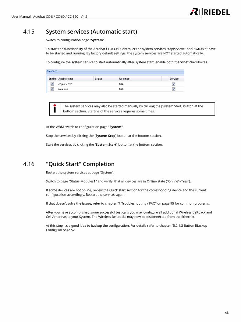
User Manual Acrobat CC-8 / CC-60 / CC-120 V4.2
43
4.15 System services (Automatic start) Switch to configuration page "System". To start the functionality of the Acrobat CC-8 Cell Controller the system services "capisrv.exe" and "iwu.exe" have to be started and running. By factory default settings, the system services are NOT started automatically. To configure the system service to start automatically after system start, enable both "Service" checkboxes.
The system services may also be started manually by clicking the [System Start] button at the bottom section. Starting of the services requires some times.
At the WBM switch to configuration page "System". Stop the services by clicking the [System Stop] button at the bottom section. Start the services by clicking the [System Start] button at the bottom section.
4.16 "Quick Start" Completion Restart the system services at page "System". Switch to page "Status-Modules1" and verify, that all devices are in Online state ("Online"="Yes"). If some devices are not online, review the Quick start section for the corresponding device and the current configuration accordingly. Restart the services again. If that doesn’t solve the issues, refer to chapter “7 Troubleshooting / FAQ” on page 95 for common problems. After you have accomplished some successful test calls you may configure all additional Wireless Beltpack and Cell Antennas to your System. The Wireless Beltpacks may now be disconnected from the Ethernet. At this step it’s a good idea to backup the configuration. For details refer to chapter "5.2.1.3 Button [Backup Config]"on page 52.
User Manual Acrobat CC-8 / CC-60 / CC-120 V4.2
44
4.17 Further steps
4.17.1 Radio frequency site survey A radio frequency site survey has to be performed. Within this step, also the synchronization concept has to be designed, implemented and tested.
4.17.2 Synchronization implementation The synchronization implementation should be part of the radio frequency site survey. For details of synchronization refer to chapter “2.6 Synchronization via Ethernet (acc. IEEE1588)” on page 10.
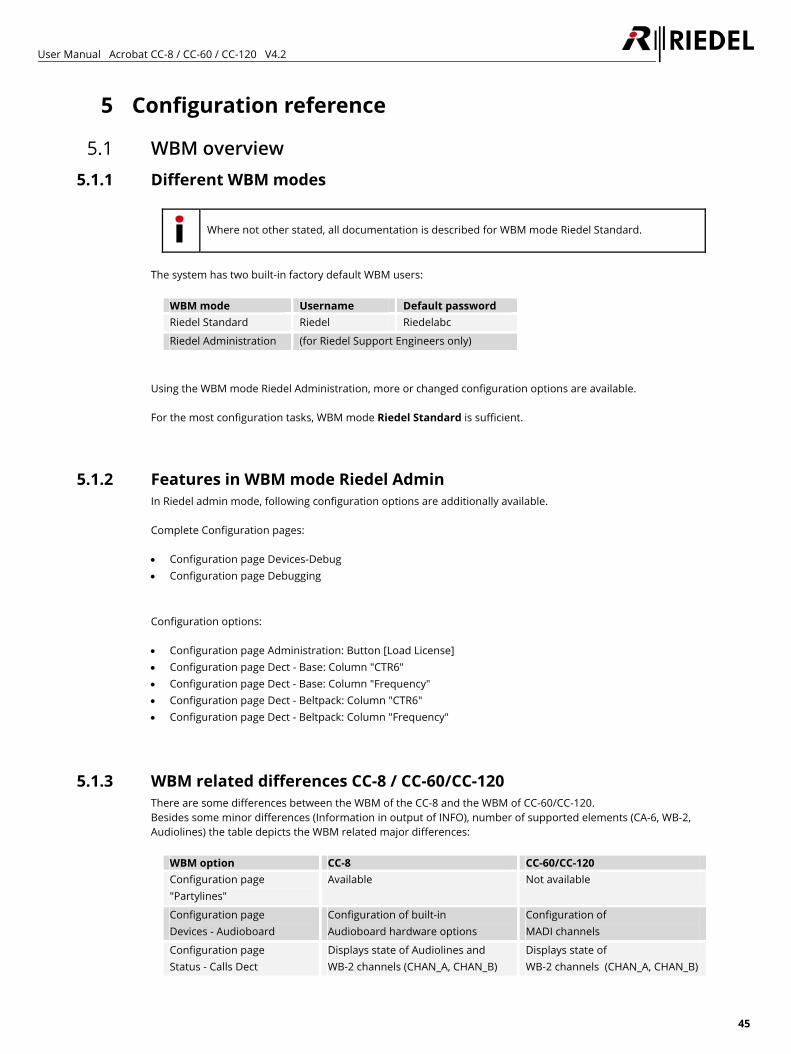
User Manual Acrobat CC-8 / CC-60 / CC-120 V4.2
45
5 Configuration reference
5.1 WBM overview 5.1.1 Different WBM modes
Where not other stated, all documentation is described for WBM mode Riedel Standard.
The system has two built-in factory default WBM users:
WBM mode Username Default password Riedel Standard Riedel Riedelabc
Riedel Administration (for Riedel Support Engineers only)
Using the WBM mode Riedel Administration, more or changed configuration options are available. For the most configuration tasks, WBM mode Riedel Standard is sufficient.
5.1.2 Features in WBM mode Riedel Admin In Riedel admin mode, following configuration options are additionally available. Complete Configuration pages: • Configuration page Devices-Debug • Configuration page Debugging Configuration options: • Configuration page Administration: Button [Load License] • Configuration page Dect - Base: Column "CTR6" • Configuration page Dect - Base: Column "Frequency" • Configuration page Dect - Beltpack: Column "CTR6" • Configuration page Dect - Beltpack: Column "Frequency"
5.1.3 WBM related differences CC-8 / CC-60/CC-120 There are some differences between the WBM of the CC-8 and the WBM of CC-60/CC-120. Besides some minor differences (Information in output of INFO), number of supported elements (CA-6, WB-2, Audiolines) the table depicts the WBM related major differences:
WBM option CC-8 CC-60/CC-120 Configuration page "Partylines"
Available Not available
Configuration page Devices - Audioboard
Configuration of built-in Audioboard hardware options
Configuration of MADI channels
Configuration page Status - Calls Dect
Displays state of Audiolines and WB-2 channels (CHAN_A, CHAN_B)
Displays state of WB-2 channels (CHAN_A, CHAN_B)
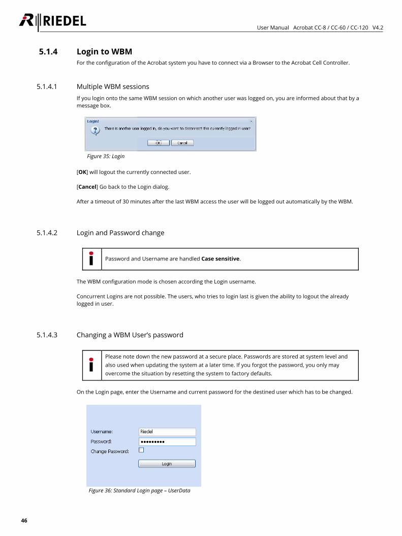
User Manual Acrobat CC-8 / CC-60 / CC-120 V4.2
46
5.1.4 Login to WBM For the configuration of the Acrobat system you have to connect via a Browser to the Acrobat Cell Controller.
5.1.4.1 Multiple WBM sessions If you login onto the same WBM session on which another user was logged on, you are informed about that by a message box.
Figure 35: Login
[OK] will logout the currently connected user. [Cancel] Go back to the Login dialog. After a timeout of 30 minutes after the last WBM access the user will be logged out automatically by the WBM.
5.1.4.2 Login and Password change
Password and Username are handled Case sensitive.
The WBM configuration mode is chosen according the Login username. Concurrent Logins are not possible. The users, who tries to login last is given the ability to logout the already logged in user.
5.1.4.3 Changing a WBM User’s password
Please note down the new password at a secure place. Passwords are stored at system level and also used when updating the system at a later time. If you forgot the password, you only may overcome the situation by resetting the system to factory defaults.
On the Login page, enter the Username and current password for the destined user which has to be changed.
Figure 36: Standard Login page – UserData
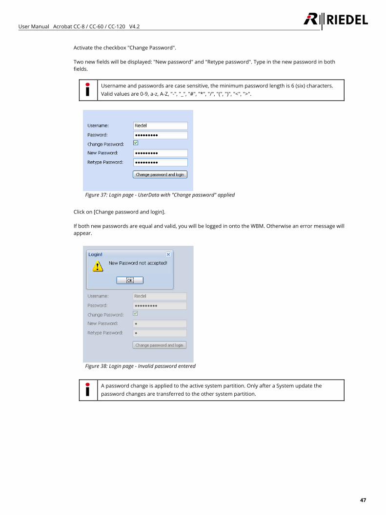
User Manual Acrobat CC-8 / CC-60 / CC-120 V4.2
47
Activate the checkbox "Change Password". Two new fields will be displayed: "New password" and "Retype password". Type in the new password in both fields.
Username and passwords are case sensitive, the minimum password length is 6 (six) characters. Valid values are 0-9, a-z, A-Z, "-", "_", "#", "*", "/", "(", ")", "<", ">".
Figure 37: Login page - UserData with "Change password" applied
Click on [Change password and login]. If both new passwords are equal and valid, you will be logged in onto the WBM. Otherwise an error message will appear.
Figure 38: Login page - Invalid password entered
A password change is applied to the active system partition. Only after a System update the password changes are transferred to the other system partition.
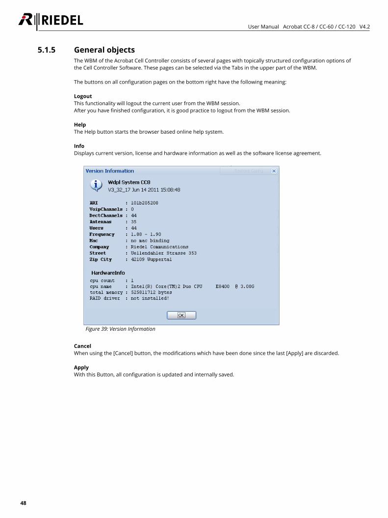
User Manual Acrobat CC-8 / CC-60 / CC-120 V4.2
48
5.1.5 General objects The WBM of the Acrobat Cell Controller consists of several pages with topically structured configuration options of the Cell Controller Software. These pages can be selected via the Tabs in the upper part of the WBM. The buttons on all configuration pages on the bottom right have the following meaning: Logout This functionality will logout the current user from the WBM session. After you have finished configuration, it is good practice to logout from the WBM session. Help The Help button starts the browser based online help system. Info Displays current version, license and hardware information as well as the software license agreement.
Figure 39: Version Information
Cancel When using the [Cancel] button, the modifications which have been done since the last [Apply] are discarded. Apply With this Button, all configuration is updated and internally saved.
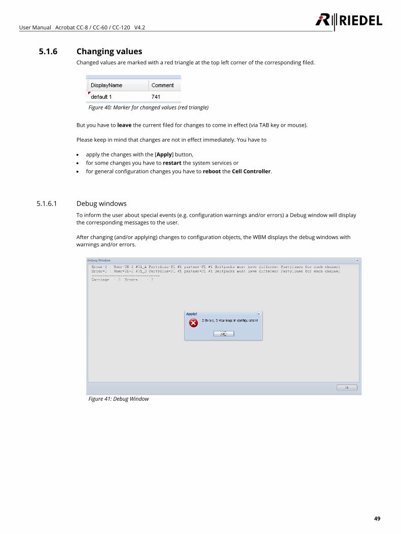
User Manual Acrobat CC-8 / CC-60 / CC-120 V4.2
49
5.1.6 Changing values Changed values are marked with a red triangle at the top left corner of the corresponding filed.
Figure 40: Marker for changed values (red triangle)
But you have to leave the current filed for changes to come in effect (via TAB key or mouse). Please keep in mind that changes are not in effect immediately. You have to • apply the changes with the [Apply] button, • for some changes you have to restart the system services or • for general configuration changes you have to reboot the Cell Controller.
5.1.6.1 Debug windows To inform the user about special events (e.g. configuration warnings and/or errors) a Debug window will display the corresponding messages to the user. After changing (and/or applying) changes to configuration objects, the WBM displays the debug windows with warnings and/or errors.
Figure 41: Debug Window
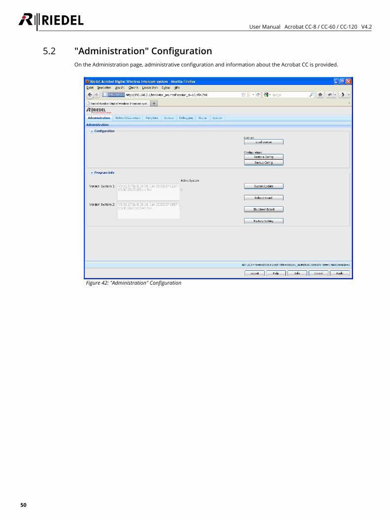
User Manual Acrobat CC-8 / CC-60 / CC-120 V4.2
50
5.2 "Administration" Configuration On the Administration page, administrative configuration and information about the Acrobat CC is provided.
Figure 42: "Administration" Configuration
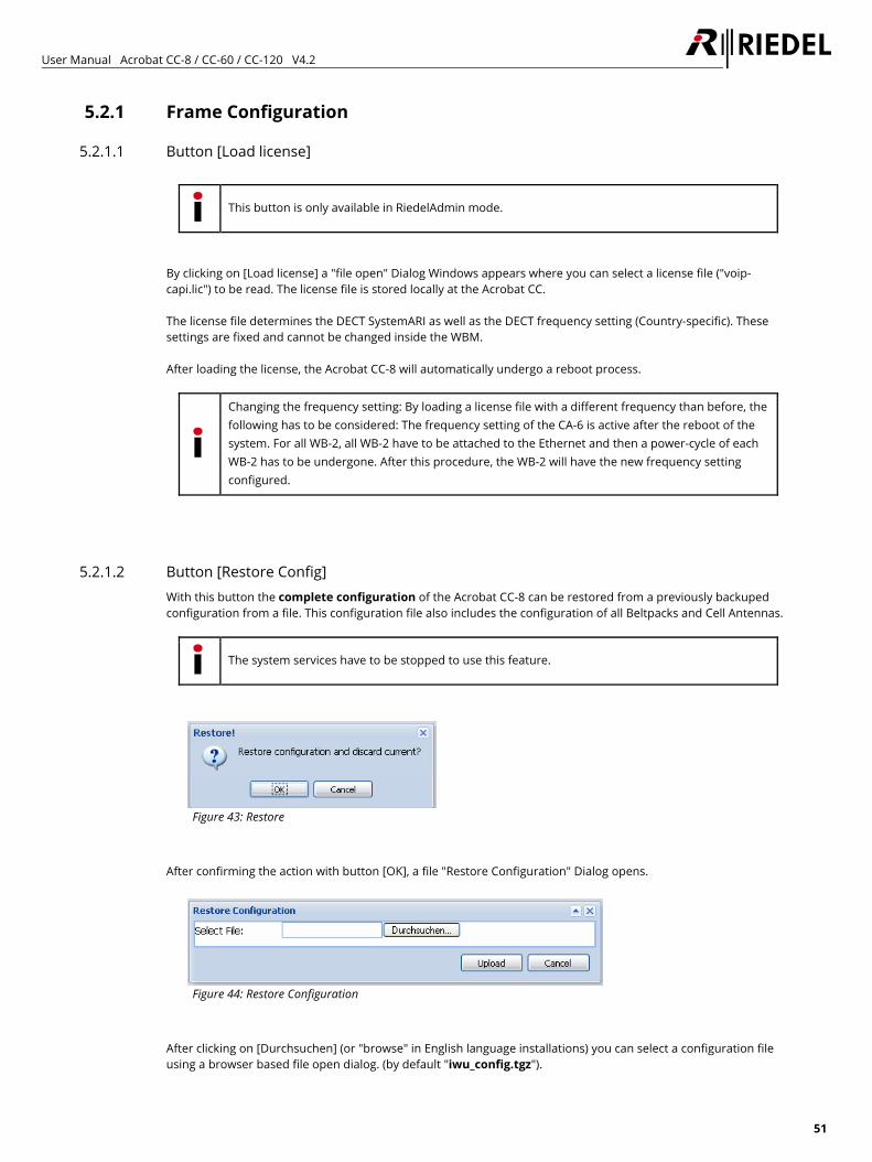
User Manual Acrobat CC-8 / CC-60 / CC-120 V4.2
51
5.2.1 Frame Configuration
5.2.1.1 Button [Load license]
This button is only available in RiedelAdmin mode.
By clicking on [Load license] a "file open" Dialog Windows appears where you can select a license file ("voip-capi.lic") to be read. The license file is stored locally at the Acrobat CC. The license file determines the DECT SystemARI as well as the DECT frequency setting (Country-specific). These settings are fixed and cannot be changed inside the WBM. After loading the license, the Acrobat CC-8 will automatically undergo a reboot process.
Changing the frequency setting: By loading a license file with a different frequency than before, the following has to be considered: The frequency setting of the CA-6 is active after the reboot of the system. For all WB-2, all WB-2 have to be attached to the Ethernet and then a power-cycle of each WB-2 has to be undergone. After this procedure, the WB-2 will have the new frequency setting configured.
5.2.1.2 Button [Restore Config] With this button the complete configuration of the Acrobat CC-8 can be restored from a previously backuped configuration from a file. This configuration file also includes the configuration of all Beltpacks and Cell Antennas.
The system services have to be stopped to use this feature.
Figure 43: Restore
After confirming the action with button [OK], a file "Restore Configuration" Dialog opens.
Figure 44: Restore Configuration
After clicking on [Durchsuchen] (or "browse" in English language installations) you can select a configuration file using a browser based file open dialog. (by default "iwu_config.tgz").
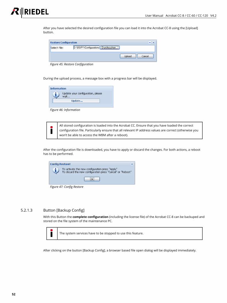
User Manual Acrobat CC-8 / CC-60 / CC-120 V4.2
52
After you have selected the desired configuration file you can load it into the Acrobat CC-8 using the [Upload] button.
Figure 45: Restore Configuration
During the upload process, a message box with a progress bar will be displayed.
Figure 46: Information
All stored configuration is loaded into the Acrobat CC. Ensure that you have loaded the correct configuration file. Particularly ensure that all relevant IP address values are correct (otherwise you won’t be able to access the WBM after a reboot).
After the configuration file is downloaded, you have to apply or discard the changes. For both actions, a reboot has to be performed.
Figure 47: Config Restore
5.2.1.3 Button [Backup Config] With this Button the complete configuration (including the license file) of the Acrobat CC-8 can be backuped and stored on the file system of the maintenance PC.
The system services have to be stopped to use this feature.
After clicking on the button [Backup Config], a browser based file open dialog will be displayed immediately.
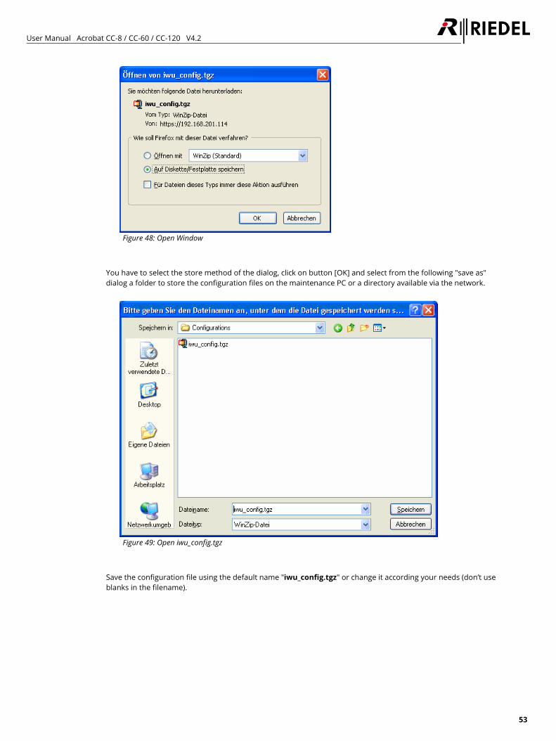
User Manual Acrobat CC-8 / CC-60 / CC-120 V4.2
53
Figure 48: Open Window
You have to select the store method of the dialog, click on button [OK] and select from the following "save as" dialog a folder to store the configuration files on the maintenance PC or a directory available via the network.
Figure 49: Open iwu_config.tgz
Save the configuration file using the default name "iwu_config.tgz" or change it according your needs (don’t use blanks in the filename).
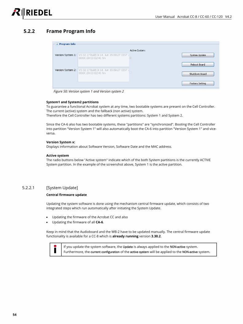
User Manual Acrobat CC-8 / CC-60 / CC-120 V4.2
54
5.2.2 Frame Program Info
Figure 50: Version system 1 and Version system 2
System1 and System2 partitions To guarantee a functional Acrobat system at any time, two bootable systems are present on the Cell Controller. The current (active) system and the fallback (non active) system. Therefore the Cell Controller has two different systems partitions: System 1 and System 2. Since the CA-6 also has two bootable systems, these "partitions" are "synchronized". Booting the Cell Controller into partition "Version System 1" will also automatically boot the CA-6 into partition "Version System 1" and vice-versa. Version System x: Displays information about Software Version, Software Date and the MAC address. Active system The radio buttons below "Active system" indicate which of the both System partitions is the currently ACTIVE System partition. In the example of the screenshot above, System 1 is the active partition.
5.2.2.1 [System Update] Central firmware update Updating the system software is done using the mechanism central firmware update, which consists of two integrated steps which run automatically after initiating the System Update. • Updating the firmware of the Acrobat CC and also • Updating the firmware of all CA-6. Keep in mind that the Audioboard and the WB-2 have to be updated manually. The central firmware update functionality is available for a CC-8 which is already running version 3.30.2.
If you update the system software, the Update is always applied to the NON-active system. Furthermore, the current configuration of the active system will be applied to the NON-active system.
User Manual Acrobat CC-8 / CC-60 / CC-120 V4.2
55
Partition synchronization If an update is started if Partition 1 of the Acrobat CC is the active partition, the Update will be applied to non-active partition 2 in this case. The update mechanism also starts the updates for all activated CA-6 into the same Partition 2. If one or several CA-6 have a "wrong" active partition (the active partition fifers from the active partition of the Acrobat CC), a message box will inform about that. In this case, no update is applied to these CA-6 and therefore they "stay" in their current partition. After the update is finished, the Acrobat CC has to be rebooted with the other partition marked as Boot system. All active CA-6 will also be rebooted automatically and switch their partition to the new active partition number if necessary. If later the partition of the Acrobat CC will be changed (e.g. after an update), all CA-6 will also switch their partition. This ensures a reliable fallback scenario (e.g. to the last version) for the whole installation (CC and CA-6).
To synchronize the CC-8 and all CA-6, simply apply a System update twice. This will force all components into the same partition.
Downgrade A downgrade is not fully supported. In need of a downgrade, a factory reset is applied automatically. Please refer to the delivered release notes of the new version for details of the update process. Update instructions 1. Please create a backup of the old configuration (Page Registration - [Backup Config]. 2. Ensure that you have a firmware file of the old version available (in case of a necessary downgrade). 3. Start with the update for the Acrobat CC. After the process has finished check at page Devices-About- PartInfo1 and PartInfo2 if all CA-6 already are updated successfully. Wait until all CA-6 are updated correctly (Version displayed in PartInfo1 resp. PartInfo2 should be unequal "n/a"). 4. Reboot the CC with the other (inactive) partition where the update has been applied to. Therefore select page Administration. Toggle the Radio Button "Boot System" from the partition which was marked active (see radio button "Active System") to the opposite partition. [Apply] the change and select [Reboot Board] to reboot the whole Acrobat CC system. 5. Apply the update to all other devices (Audioboard and WB-2) and reboot them. 6. Restart the services at the Acrobat CC.
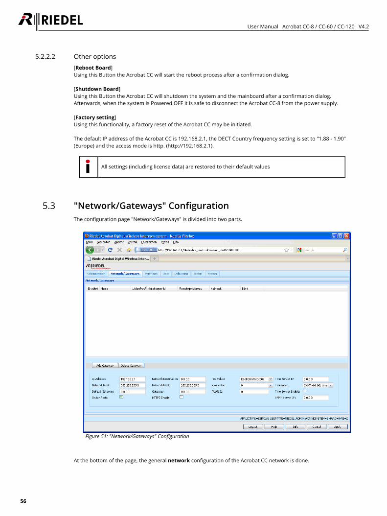
User Manual Acrobat CC-8 / CC-60 / CC-120 V4.2
56
5.2.2.2 Other options [Reboot Board] Using this Button the Acrobat CC will start the reboot process after a confirmation dialog. [Shutdown Board] Using this Button the Acrobat CC will shutdown the system and the mainboard after a confirmation dialog. Afterwards, when the system is Powered OFF it is safe to disconnect the Acrobat CC-8 from the power supply. [Factory setting] Using this functionality, a factory reset of the Acrobat CC may be initiated. The default IP address of the Acrobat CC is 192.168.2.1, the DECT Country frequency setting is set to "1.88 - 1.90" (Europe) and the access mode is http. (http://192.168.2.1).
All settings (including license data) are restored to their default values
5.3 "Network/Gateways" Configuration The configuration page "Network/Gateways" is divided into two parts.
Figure 51: "Network/Gateways" Configuration
At the bottom of the page, the general network configuration of the Acrobat CC network is done.
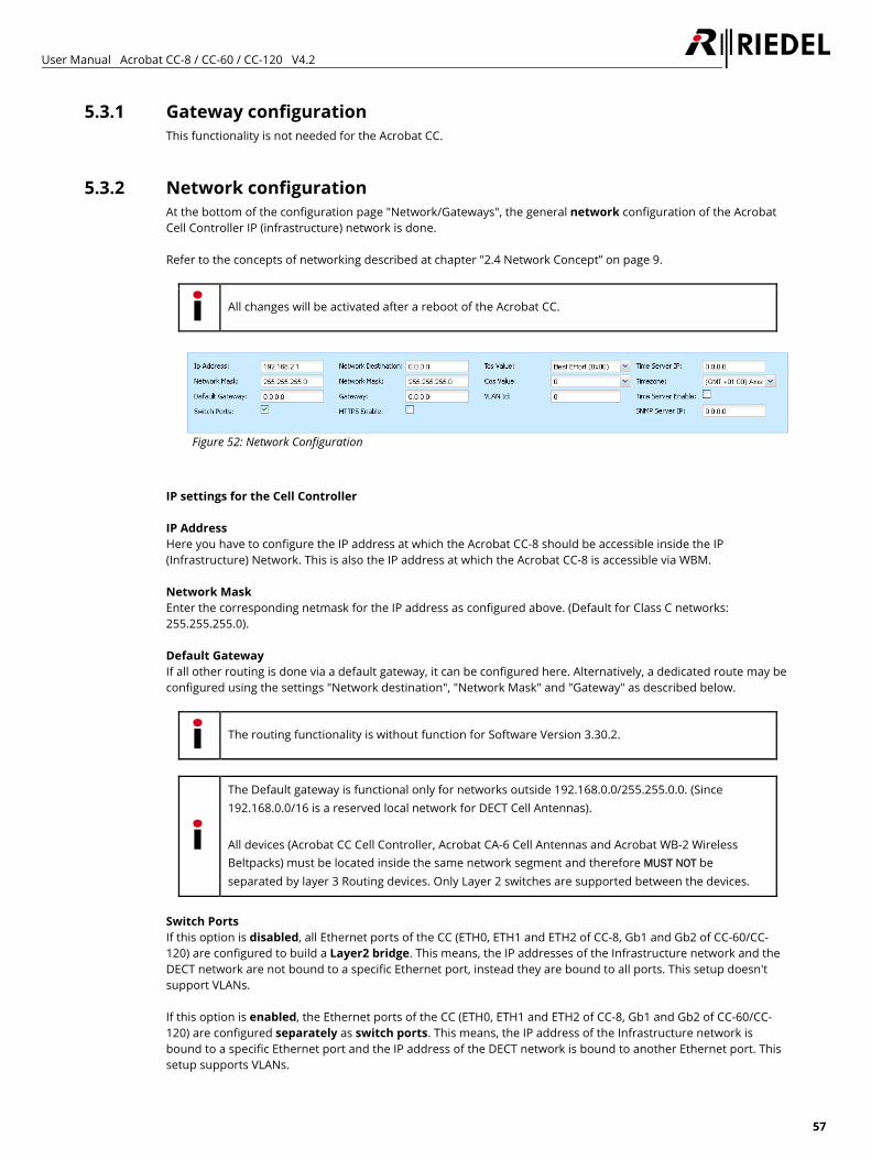
User Manual Acrobat CC-8 / CC-60 / CC-120 V4.2
57
5.3.1 Gateway configuration This functionality is not needed for the Acrobat CC.
5.3.2 Network configuration At the bottom of the configuration page "Network/Gateways", the general network configuration of the Acrobat Cell Controller IP (infrastructure) network is done. Refer to the concepts of networking described at chapter "2.4 Network Concept” on page 9.
All changes will be activated after a reboot of the Acrobat CC.
Figure 52: Network Configuration
IP settings for the Cell Controller IP Address Here you have to configure the IP address at which the Acrobat CC-8 should be accessible inside the IP (Infrastructure) Network. This is also the IP address at which the Acrobat CC-8 is accessible via WBM. Network Mask Enter the corresponding netmask for the IP address as configured above. (Default for Class C networks: 255.255.255.0). Default Gateway If all other routing is done via a default gateway, it can be configured here. Alternatively, a dedicated route may be configured using the settings "Network destination", "Network Mask" and "Gateway" as described below.
The routing functionality is without function for Software Version 3.30.2.
The Default gateway is functional only for networks outside 192.168.0.0/255.255.0.0. (Since 192.168.0.0/16 is a reserved local network for DECT Cell Antennas). All devices (Acrobat CC Cell Controller, Acrobat CA-6 Cell Antennas and Acrobat WB-2 Wireless Beltpacks) must be located inside the same network segment and therefore MUST NOT be separated by layer 3 Routing devices. Only Layer 2 switches are supported between the devices.
Switch Ports If this option is disabled, all Ethernet ports of the CC (ETH0, ETH1 and ETH2 of CC-8, Gb1 and Gb2 of CC-60/CC-120) are configured to build a Layer2 bridge. This means, the IP addresses of the Infrastructure network and the DECT network are not bound to a specific Ethernet port, instead they are bound to all ports. This setup doesn't support VLANs. If this option is enabled, the Ethernet ports of the CC (ETH0, ETH1 and ETH2 of CC-8, Gb1 and Gb2 of CC-60/CC-120) are configured separately as switch ports. This means, the IP address of the Infrastructure network is bound to a specific Ethernet port and the IP address of the DECT network is bound to another Ethernet port. This setup supports VLANs.
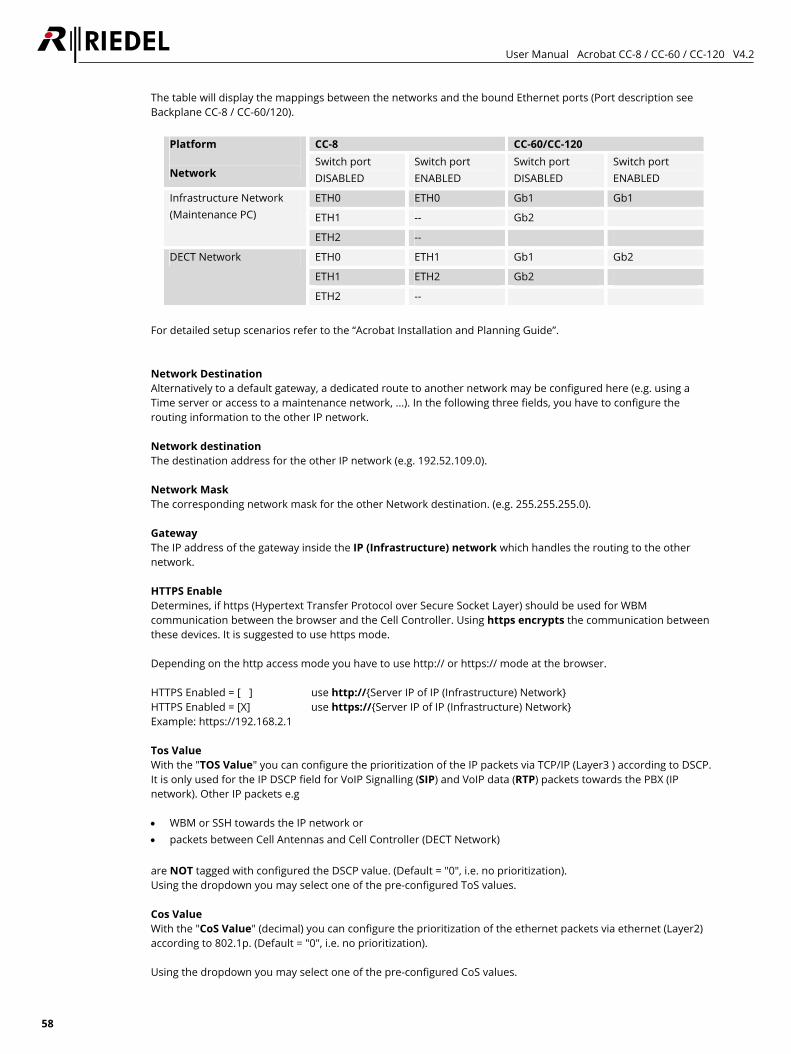
User Manual Acrobat CC-8 / CC-60 / CC-120 V4.2
58
The table will display the mappings between the networks and the bound Ethernet ports (Port description see Backplane CC-8 / CC-60/120).
CC-8 CC-60/CC-120 Platform Network
Switch port DISABLED
Switch port ENABLED
Switch port DISABLED
Switch port ENABLED
ETH0 ETH0 Gb1 Gb1
ETH1 -- Gb2
Infrastructure Network (Maintenance PC)
ETH2 --
ETH0 ETH1 Gb1 Gb2
ETH1 ETH2 Gb2
DECT Network
ETH2 --
For detailed setup scenarios refer to the “Acrobat Installation and Planning Guide”. Network Destination Alternatively to a default gateway, a dedicated route to another network may be configured here (e.g. using a Time server or access to a maintenance network, ...). In the following three fields, you have to configure the routing information to the other IP network. Network destination The destination address for the other IP network (e.g. 192.52.109.0). Network Mask The corresponding network mask for the other Network destination. (e.g. 255.255.255.0). Gateway The IP address of the gateway inside the IP (Infrastructure) network which handles the routing to the other network. HTTPS Enable Determines, if https (Hypertext Transfer Protocol over Secure Socket Layer) should be used for WBM communication between the browser and the Cell Controller. Using https encrypts the communication between these devices. It is suggested to use https mode. Depending on the http access mode you have to use http:// or https:// mode at the browser. HTTPS Enabled = [ ] use http://{Server IP of IP (Infrastructure) Network} HTTPS Enabled = [X] use https://{Server IP of IP (Infrastructure) Network} Example: https://192.168.2.1 Tos Value With the "TOS Value" you can configure the prioritization of the IP packets via TCP/IP (Layer3 ) according to DSCP. It is only used for the IP DSCP field for VoIP Signalling (SIP) and VoIP data (RTP) packets towards the PBX (IP network). Other IP packets e.g • WBM or SSH towards the IP network or • packets between Cell Antennas and Cell Controller (DECT Network) are NOT tagged with configured the DSCP value. (Default = "0", i.e. no prioritization). Using the dropdown you may select one of the pre-configured ToS values. Cos Value With the "CoS Value" (decimal) you can configure the prioritization of the ethernet packets via ethernet (Layer2) according to 802.1p. (Default = "0", i.e. no prioritization). Using the dropdown you may select one of the pre-configured CoS values.
User Manual Acrobat CC-8 / CC-60 / CC-120 V4.2
59
VLAN Id The corresponding VLAN Id (according IEEE 802.1q) is configured here. If VLANs are used (value unequal to "0"), the switch port connected with the Acrobat CC has to be configured to tag the Ethernet frames. VLAN configuration is activated, if the VLAN Id is configured to a valid VLAN Id unequal to 0. If VLAN is activated, the Cell Controller sends and expects to receive tagged Ethernet packets. Therefore the switch port to which the CC is connected to, has to be configured to tag the Ethernet frames with the VLAN Ids. Tagging has to be established for the VLAN Id of the IP (Infrastructure) network (this VLAN Id) AND for the VLAN Id of the DECT network. All Ethernet frames towards the IP (Infrastructure) network between the CC and the Ethernet switch are tagged with the configured VLAN Id configured for the Infrastructure network (option "VLAN Id" at page Network/Gateways - this option). All Ethernet frames towards the DECT network between the Cell Controller and the Ethernet switch are tagged with the configured VLAN Id configured for the DECT network (option "VLAN Id" at page DECT). Please take account of the correlating VLAN configuration of the DECT network at chapter "5.5.7.2 General configuration options" on page 72. Time Server IP Exact time information may be derived from a NTP (or SNTP) time server. The IP address of the Time Server is configured here. If a time server is not configured correctly and cannot be contacted, the local time of the PC mainboard of the Acrobat CC will be used. Timezone If using a Time Server, the Timezone has to be configured according the physical location of the Acrobat Digital Wireless Intercom system (country). Since NTP is always using UTC time, the local time has to be calculated against the time zone information to get correct current Local time. Time Server Enable Enables the usage of the Time Server. SNMP Server IP Using this option, an IP address of a SNMP server may be configured here to which SNMP traps are being send. For details refer to chapter "6.1.2 SNMP" on page 89.
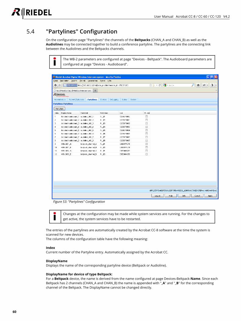
User Manual Acrobat CC-8 / CC-60 / CC-120 V4.2
60
5.4 "Partylines" Configuration On the configuration page "Partylines" the channels of the Beltpacks (CHAN_A and CHAN_B) as well as the Audiolines may be connected together to build a conference partyline. The partylines are the connecting link between the Audiolines and the Beltpacks channels.
The WB-2 parameters are configured at page "Devices - Beltpack". The Audioboard parameters are configured at page "Devices - Audioboard".
Figure 53: "Partylines" Configuration
Changes at the configuration may be made while system services are running. For the changes to get active, the system services have to be restarted.
The entries of the partylines are automatically created by the Acrobat CC-8 software at the time the system is scanned for new devices. The columns of the configuration table have the following meaning: Index Current number of the Partyline entry. Automatically assigned by the Acrobat CC. DisplayName Displays the name of the corresponding partyline device (Beltpack or Audioline). DisplayName for device of type Beltpack: For a Beltpack device, the name is derived from the name configured at page Devices-Beltpack-Name. Since each Beltpack has 2 channels (CHAN_A and CHAN_B) the name is appended with "_A" and "_B" for the corresponding channel of the Beltpack. The DisplayName cannot be changed directly.
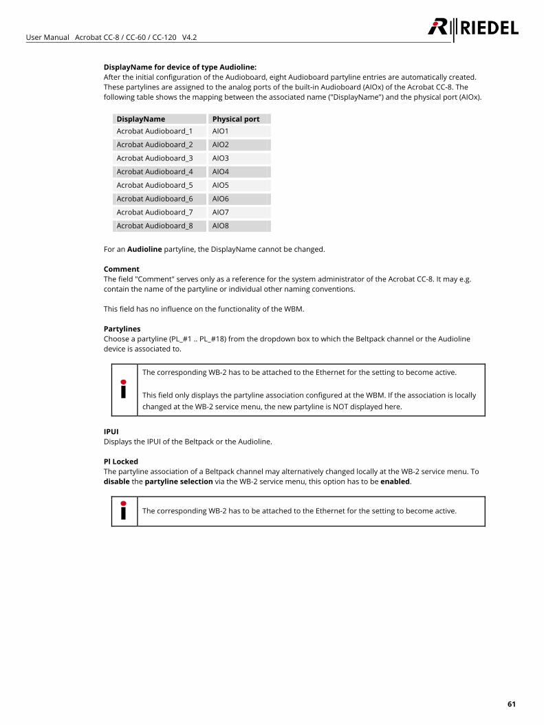
User Manual Acrobat CC-8 / CC-60 / CC-120 V4.2
61
DisplayName for device of type Audioline: After the initial configuration of the Audioboard, eight Audioboard partyline entries are automatically created. These partylines are assigned to the analog ports of the built-in Audioboard (AIOx) of the Acrobat CC-8. The following table shows the mapping between the associated name ("DisplayName") and the physical port (AIOx).
DisplayName Physical port Acrobat Audioboard_1 AIO1
Acrobat Audioboard_2 AIO2
Acrobat Audioboard_3 AIO3
Acrobat Audioboard_4 AIO4
Acrobat Audioboard_5 AIO5
Acrobat Audioboard_6 AIO6
Acrobat Audioboard_7 AIO7
Acrobat Audioboard_8 AIO8
For an Audioline partyline, the DisplayName cannot be changed. Comment The field "Comment" serves only as a reference for the system administrator of the Acrobat CC-8. It may e.g. contain the name of the partyline or individual other naming conventions. This field has no influence on the functionality of the WBM. Partylines Choose a partyline (PL_#1 .. PL_#18) from the dropdown box to which the Beltpack channel or the Audioline device is associated to.
The corresponding WB-2 has to be attached to the Ethernet for the setting to become active. This field only displays the partyline association configured at the WBM. If the association is locally changed at the WB-2 service menu, the new partyline is NOT displayed here.
IPUI Displays the IPUI of the Beltpack or the Audioline. Pl Locked The partyline association of a Beltpack channel may alternatively changed locally at the WB-2 service menu. To disable the partyline selection via the WB-2 service menu, this option has to be enabled.
The corresponding WB-2 has to be attached to the Ethernet for the setting to become active.

User Manual Acrobat CC-8 / CC-60 / CC-120 V4.2
62
5.5 "Devices" Configuration On the main configuration page "Devices" the hardware configuration of the • Acrobat CA-6 Cell Antenna, the • Acrobat WB-2 Wireless Beltpacks and the • Acrobat CC-8 Audioboard is accomplished. This page contains the sub configuration pages "Base", "Beltpack", "Audioboard", "Sync", "About". and (only in RiedelAdmin mode) "Debug".
Figure 54: "Devices" Configuration
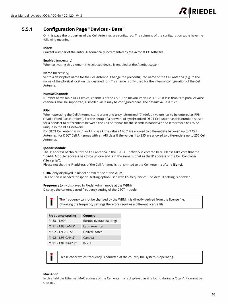
User Manual Acrobat CC-8 / CC-60 / CC-120 V4.2
63
5.5.1 Configuration Page "Devices - Base" On this page the properties of the Cell Antennas are configured. The columns of the configuration table have the following meaning: Index Current number of the entry. Automatically incremented by the Acrobat CC software. Enabled (necessary) When activating this element the selected device is enabled at the Acrobat system. Name (necessary) Set to a descriptive name for the Cell Antenna. Change the preconfigured name of the Cell Antenna (e.g. to the name of the physical location it is destined for). This name is only used for the internal configuration of the Cell Antenna. NumOfChannels Number of available DECT (voice) channels of the CA-6. The maximum value is "12". If less than "12" parallel voice channels shall be supported, a smaller value may be configured here. The default value is "12". RPN When operating the Cell Antenna stand alone and unsynchronized "0" (default value) has to be entered as RPN ("Radio Fixed Part Number"). For the setup of a network of synchronized DECT Cell Antennas this number is used for a handset to differentiate between the Cell Antennas for the seamless handover and it therefore has to be unique in the DECT network. For DECT Cell Antennas with an ARI class A the values 1 to 7 are allowed to differentiate between up to 7 Cell Antennas, for DECT Cell Antennas with an ARI class B the values 1 to 255 are allowed to differentiate up to 255 Cell Antennas. IpAddr Module The IP address of choice for the Cell Antenna in the IP-DECT network is entered here. Please take care that the "IpAddr Module" address has to be unique and is in the same subnet as the IP address of the Cell Controller ("Server Ip"). Please not that the IP address of the Cell Antenna is transmitted to the Cell Antenna after a [Sync]. CTR6 (only displayed in Riedel Admin mode at the WBM) This option is needed for special testing option used with US frequencies. The default setting is disabled. Frequency (only displayed in Riedel Admin mode at the WBM) Displays the currently used frequency setting of the DECT module.
The frequency cannot be changed by the WBM. It is directly derived from the license file. Changing the frequency settings therefore requires a different license file.
Frequency setting Country "1.88 - 1.90" Europe (Default setting)
"1.91 - 1.93 LAM S" Latin America
"1.92 - 1.93 US S" United States
"1.92 - 1.93 CAN S" Canada
"1.91 - 1.92 BRAZ S" Brazil
Please check which frequency is admitted at the country the system is operating.
Mac Addr In this field the Ethernet MAC address of the Cell Antenna is displayed as it is found during a "Scan". It cannot be changed.
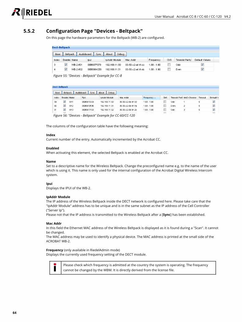
User Manual Acrobat CC-8 / CC-60 / CC-120 V4.2
64
5.5.2 Configuration Page "Devices - Beltpack" On this page the hardware parameters for the Beltpack (WB-2) are configured.
Figure 55: "Devices - Beltpack" Example for CC-8
Figure 56: "Devices - Beltpack" Example for CC-60/CC-120
The columns of the configuration table have the following meaning: Index Current number of the entry. Automatically incremented by the Acrobat CC. Enabled When activating this element, the selected Beltpack is enabled at the Acrobat CC. Name Set to a descriptive name for the Wireless Beltpack. Change the preconfigured name e.g. to the name of the user which is using it. This name is only used for the internal configuration of the Acrobat Digital Wireless Intercom system. Ipui Displays the IPUI of the WB-2. IpAddr Module The IP address of the Wireless Beltpack inside the DECT network is configured here. Please take care that the "IpAddr Module" address has to be unique and is in the same subnet as the IP address of the Cell Controller ("Server Ip"). Please not that the IP address is transmitted to the Wireless Beltpack after a [Sync] has been established. Mac Addr In this field the Ethernet MAC address of the Wireless Beltpack is displayed as it is found during a "Scan". It cannot be changed. The MAC address may be used to identify a physical device. The MAC address is printed at the small side of the ACROBAT WB-2. Frequency (only available in RiedelAdmin mode) Displays the currently used frequency setting of the DECT module.
Please check which frequency is admitted at the country the system is operating. The frequency cannot be changed by the WBM. It is directly derived from the license file.
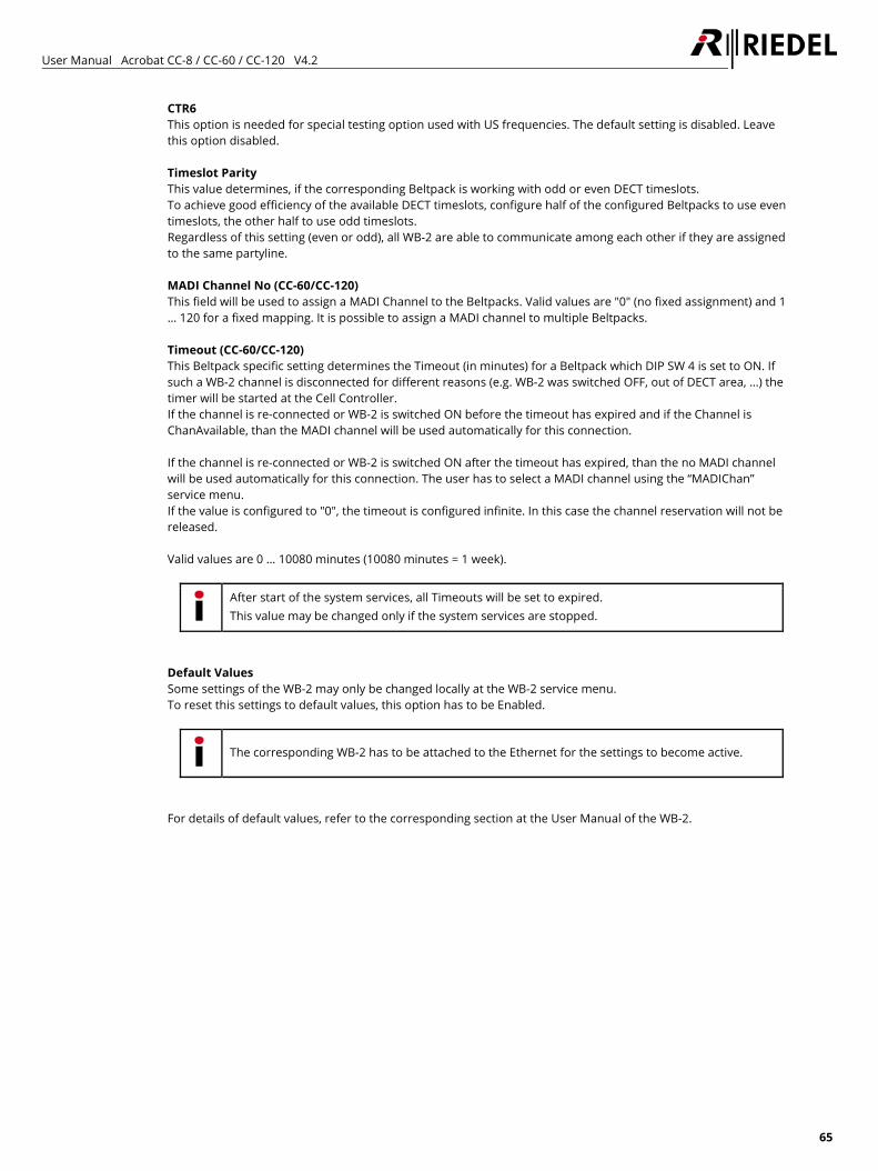
User Manual Acrobat CC-8 / CC-60 / CC-120 V4.2
65
CTR6 This option is needed for special testing option used with US frequencies. The default setting is disabled. Leave this option disabled. Timeslot Parity This value determines, if the corresponding Beltpack is working with odd or even DECT timeslots. To achieve good efficiency of the available DECT timeslots, configure half of the configured Beltpacks to use even timeslots, the other half to use odd timeslots. Regardless of this setting (even or odd), all WB-2 are able to communicate among each other if they are assigned to the same partyline. MADI Channel No (CC-60/CC-120) This field will be used to assign a MADI Channel to the Beltpacks. Valid values are "0" (no fixed assignment) and 1 … 120 for a fixed mapping. It is possible to assign a MADI channel to multiple Beltpacks. Timeout (CC-60/CC-120) This Beltpack specific setting determines the Timeout (in minutes) for a Beltpack which DIP SW 4 is set to ON. If such a WB-2 channel is disconnected for different reasons (e.g. WB-2 was switched OFF, out of DECT area, …) the timer will be started at the Cell Controller. If the channel is re-connected or WB-2 is switched ON before the timeout has expired and if the Channel is ChanAvailable, than the MADI channel will be used automatically for this connection. If the channel is re-connected or WB-2 is switched ON after the timeout has expired, than the no MADI channel will be used automatically for this connection. The user has to select a MADI channel using the “MADIChan” service menu. If the value is configured to "0", the timeout is configured infinite. In this case the channel reservation will not be released. Valid values are 0 … 10080 minutes (10080 minutes = 1 week).
After start of the system services, all Timeouts will be set to expired. This value may be changed only if the system services are stopped.
Default Values Some settings of the WB-2 may only be changed locally at the WB-2 service menu. To reset this settings to default values, this option has to be Enabled.
The corresponding WB-2 has to be attached to the Ethernet for the settings to become active.
For details of default values, refer to the corresponding section at the User Manual of the WB-2.
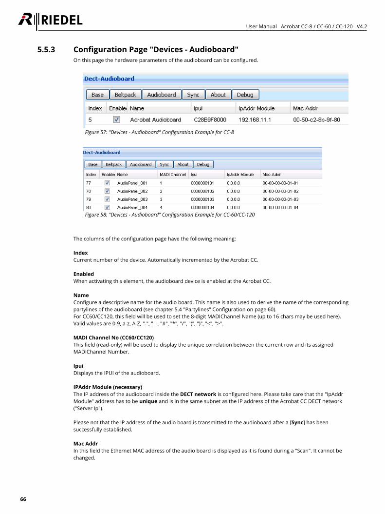
User Manual Acrobat CC-8 / CC-60 / CC-120 V4.2
66
5.5.3 Configuration Page "Devices - Audioboard" On this page the hardware parameters of the audioboard can be configured.
Figure 57: "Devices - Audioboard" Configuration Example for CC-8
Figure 58: "Devices - Audioboard" Configuration Example for CC-60/CC-120
The columns of the configuration page have the following meaning: Index Current number of the device. Automatically incremented by the Acrobat CC. Enabled When activating this element, the audioboard device is enabled at the Acrobat CC. Name Configure a descriptive name for the audio board. This name is also used to derive the name of the corresponding partylines of the audioboard (see chapter 5.4 "Partylines" Configuration on page 60). For CC60/CC120, this field will be used to set the 8-digit MADIChannel Name (up to 16 chars may be used here). Valid values are 0-9, a-z, A-Z, "-", "_", "#", "*", "/", "(", ")", "<", ">". MADI Channel No (CC60/CC120) This field (read-only) will be used to display the unique correlation between the current row and its assigned MADIChannel Number. Ipui Displays the IPUI of the audioboard. IPAddr Module (necessary) The IP address of the audioboard inside the DECT network is configured here. Please take care that the "IpAddr Module" address has to be unique and is in the same subnet as the IP address of the Acrobat CC DECT network ("Server Ip"). Please not that the IP address of the audio board is transmitted to the audioboard after a [Sync] has been successfully established. Mac Addr In this field the Ethernet MAC address of the audio board is displayed as it is found during a "Scan". It cannot be changed.
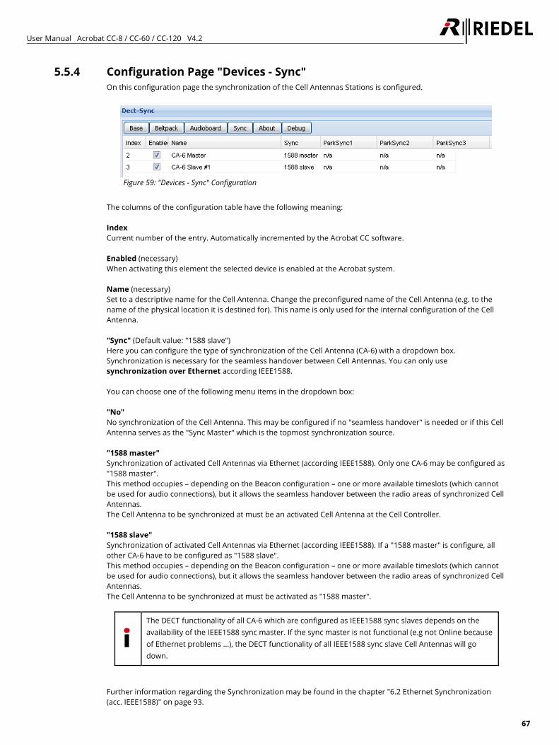
User Manual Acrobat CC-8 / CC-60 / CC-120 V4.2
67
5.5.4 Configuration Page "Devices - Sync" On this configuration page the synchronization of the Cell Antennas Stations is configured.
Figure 59: "Devices - Sync" Configuration
The columns of the configuration table have the following meaning: Index Current number of the entry. Automatically incremented by the Acrobat CC software. Enabled (necessary) When activating this element the selected device is enabled at the Acrobat system. Name (necessary) Set to a descriptive name for the Cell Antenna. Change the preconfigured name of the Cell Antenna (e.g. to the name of the physical location it is destined for). This name is only used for the internal configuration of the Cell Antenna. "Sync" (Default value: "1588 slave") Here you can configure the type of synchronization of the Cell Antenna (CA-6) with a dropdown box. Synchronization is necessary for the seamless handover between Cell Antennas. You can only use synchronization over Ethernet according IEEE1588. You can choose one of the following menu items in the dropdown box: "No" No synchronization of the Cell Antenna. This may be configured if no "seamless handover" is needed or if this Cell Antenna serves as the "Sync Master" which is the topmost synchronization source. "1588 master" Synchronization of activated Cell Antennas via Ethernet (according IEEE1588). Only one CA-6 may be configured as "1588 master". This method occupies – depending on the Beacon configuration – one or more available timeslots (which cannot be used for audio connections), but it allows the seamless handover between the radio areas of synchronized Cell Antennas. The Cell Antenna to be synchronized at must be an activated Cell Antenna at the Cell Controller. "1588 slave" Synchronization of activated Cell Antennas via Ethernet (according IEEE1588). If a "1588 master" is configure, all other CA-6 have to be configured as "1588 slave". This method occupies – depending on the Beacon configuration – one or more available timeslots (which cannot be used for audio connections), but it allows the seamless handover between the radio areas of synchronized Cell Antennas. The Cell Antenna to be synchronized at must be activated as "1588 master".
The DECT functionality of all CA-6 which are configured as IEEE1588 sync slaves depends on the availability of the IEEE1588 sync master. If the sync master is not functional (e.g not Online because of Ethernet problems …), the DECT functionality of all IEEE1588 sync slave Cell Antennas will go down.
Further information regarding the Synchronization may be found in the chapter "6.2 Ethernet Synchronization (acc. IEEE1588)" on page 93.
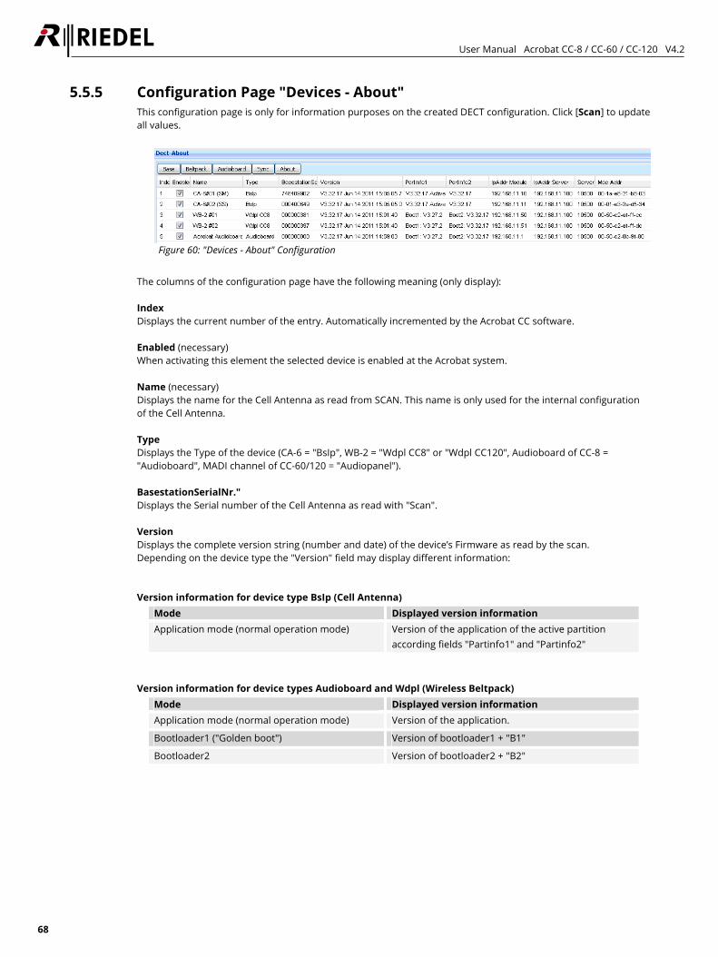
User Manual Acrobat CC-8 / CC-60 / CC-120 V4.2
68
5.5.5 Configuration Page "Devices - About" This configuration page is only for information purposes on the created DECT configuration. Click [Scan] to update all values.
Figure 60: "Devices - About" Configuration
The columns of the configuration page have the following meaning (only display): Index Displays the current number of the entry. Automatically incremented by the Acrobat CC software. Enabled (necessary) When activating this element the selected device is enabled at the Acrobat system. Name (necessary) Displays the name for the Cell Antenna as read from SCAN. This name is only used for the internal configuration of the Cell Antenna. Type Displays the Type of the device (CA-6 = "BsIp", WB-2 = "Wdpl CC8" or "Wdpl CC120", Audioboard of CC-8 = "Audioboard", MADI channel of CC-60/120 = "Audiopanel"). BasestationSerialNr." Displays the Serial number of the Cell Antenna as read with "Scan". Version Displays the complete version string (number and date) of the device’s Firmware as read by the scan. Depending on the device type the "Version" field may display different information: Version information for device type BsIp (Cell Antenna)
Mode Displayed version information Application mode (normal operation mode) Version of the application of the active partition
according fields "Partinfo1" and "Partinfo2"
Version information for device types Audioboard and Wdpl (Wireless Beltpack)
Mode Displayed version information Application mode (normal operation mode) Version of the application.
Bootloader1 ("Golden boot") Version of bootloader1 + "B1"
Bootloader2 Version of bootloader2 + "B2"
User Manual Acrobat CC-8 / CC-60 / CC-120 V4.2
69
PartInfo1 Displays the short version string (number) of the device’s Firmware as read by the scan. Depending on the device type the "PartInfo1" field may display different information:
DeviceType Displayed information of "PartInfo1" BsIp (Cell Antenna) Version of the application of Partition1
Audioboard Version of bootloader1 (Boot1)
Wdpl (Beltpack) Version of bootloader1 (Boot1)
PartInfo2 Displays the short version string (number) of the device’s Firmware as read by the scan. Depending on the device type the "PartInfo2" field may display different information:
DeviceType Displayed information of "PartInfo2" BsIp (Cell Antenna) Version of the application of Partition2
Audioboard Version of bootloader2 (Boot2)
Wdpl (Beltpack) Version of bootloader2 (Boot2)
IpAddr Module IP address of the device, as read with "Scan".
If this Ip address differs from the configured IP address (IpAddr Module) on page Device-Base, Device - Audioboard or Device-Beltpack, a SYNC process has to be established, which transfers the settings of the device configured at the CC towards the device.
IpAddr Server IP address of the DECT Server IP (DECT network) read with "Scan".
If this Ip address differs from the configured IP address (IpAddr Module) on page Device-Base, Device - Audioboard or Device-Beltpack, a SYNC process has to be established, which transfers the settings of the device configured at the CC towards the device.
Server Port Broad Displays the IP port of the device (see option "ListenPort" on WBM page "Devices") on which the Acrobat CC communicates with the device as read from the device by "Scan". Mac Addr MAC Address of the device as read from the device Station with "Scan".
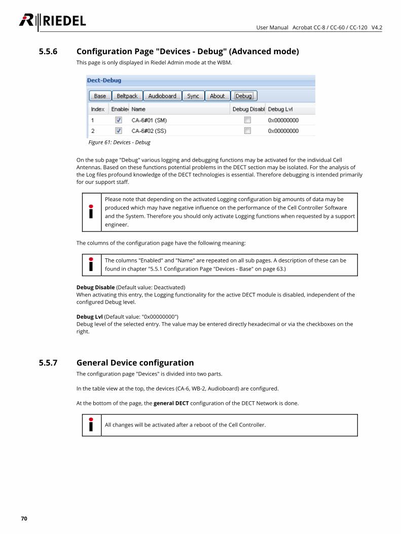
User Manual Acrobat CC-8 / CC-60 / CC-120 V4.2
70
5.5.6 Configuration Page "Devices - Debug" (Advanced mode) This page is only displayed in Riedel Admin mode at the WBM.
Figure 61: Devices - Debug
On the sub page "Debug" various logging and debugging functions may be activated for the individual Cell Antennas. Based on these functions potential problems in the DECT section may be isolated. For the analysis of the Log files profound knowledge of the DECT technologies is essential. Therefore debugging is intended primarily for our support staff.
Please note that depending on the activated Logging configuration big amounts of data may be produced which may have negative influence on the performance of the Cell Controller Software and the System. Therefore you should only activate Logging functions when requested by a support engineer.
The columns of the configuration page have the following meaning:
The columns "Enabled" and "Name" are repeated on all sub pages. A description of these can be found in chapter "5.5.1 Configuration Page "Devices - Base" on page 63.)
Debug Disable (Default value: Deactivated) When activating this entry, the Logging functionality for the active DECT module is disabled, independent of the configured Debug level. Debug Lvl (Default value: "0x00000000") Debug level of the selected entry. The value may be entered directly hexadecimal or via the checkboxes on the right.
5.5.7 General Device configuration The configuration page "Devices" is divided into two parts. In the table view at the top, the devices (CA-6, WB-2, Audioboard) are configured. At the bottom of the page, the general DECT configuration of the DECT Network is done.
All changes will be activated after a reboot of the Cell Controller.
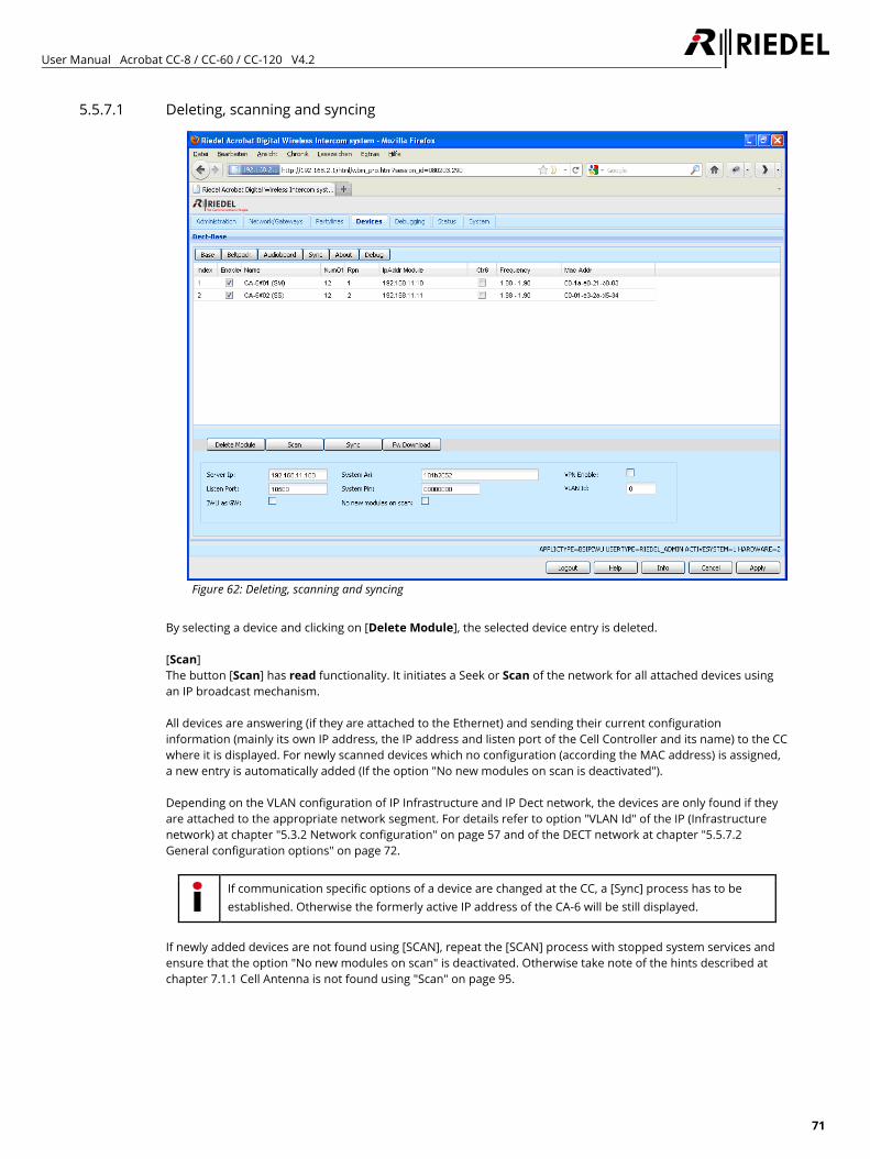
User Manual Acrobat CC-8 / CC-60 / CC-120 V4.2
71
5.5.7.1 Deleting, scanning and syncing
Figure 62: Deleting, scanning and syncing
By selecting a device and clicking on [Delete Module], the selected device entry is deleted. [Scan] The button [Scan] has read functionality. It initiates a Seek or Scan of the network for all attached devices using an IP broadcast mechanism. All devices are answering (if they are attached to the Ethernet) and sending their current configuration information (mainly its own IP address, the IP address and listen port of the Cell Controller and its name) to the CC where it is displayed. For newly scanned devices which no configuration (according the MAC address) is assigned, a new entry is automatically added (If the option "No new modules on scan is deactivated"). Depending on the VLAN configuration of IP Infrastructure and IP Dect network, the devices are only found if they are attached to the appropriate network segment. For details refer to option "VLAN Id" of the IP (Infrastructure network) at chapter "5.3.2 Network configuration" on page 57 and of the DECT network at chapter "5.5.7.2 General configuration options" on page 72.
If communication specific options of a device are changed at the CC, a [Sync] process has to be established. Otherwise the formerly active IP address of the CA-6 will be still displayed.
If newly added devices are not found using [SCAN], repeat the [SCAN] process with stopped system services and ensure that the option "No new modules on scan" is deactivated. Otherwise take note of the hints described at chapter 7.1.1 Cell Antenna is not found using "Scan" on page 95.
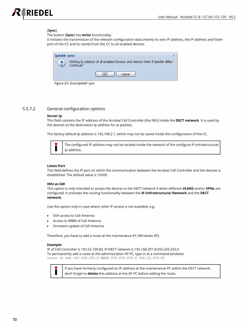
User Manual Acrobat CC-8 / CC-60 / CC-120 V4.2
72
[Sync] The button [Sync] has write functionality. It initiates the transmission of the relevant configuration data (mainly its own IP address, the IP address and listen port of the CC and its name) from the CC to all enabled devices.
Figure 63: Scan/IpAddr sync
5.5.7.2 General configuration options Server Ip This field contains the IP address of the Acrobat Cell Controller (the IWU) inside the DECT network. It is used by the devices as the destination ip address for ip packets. The factory default Ip address is 192.168.2.1, which may not be saved inside the configuration of the CC.
The configured IP address may not be located inside the network of the configure IP (Infrastructure) Ip address.
Listen Port This field defines the IP port on which the communication between the Acrobat Cell Controller and the devices is established. The default value is 10500. IWU as GW This option is only intended to access the devices in the DECT network if when different VLANS and/or VPNs are configured. It activates the routing functionality between the IP (Infrastructure) Network and the DECT network. Use this option only in case where other IP access is not available, e.g. • SSH access to Cell Antenna • Access to WBM of Cell Antenna • Firmware update of Cell Antenna Therefore, you have to add a route at the maintenance PC (Windows XP): Example: IP of Cell Controller is 192.52.109.83, IP-DECT network is 192.168.201.0/255.255.255.0 To permanently add a route at the administration XP PC, type in at a command windows: route -p add 192.168.201.0 MASK 255.255.255.0 192.52.109.83
If you have formerly configured an IP address at the maintenance PC within the DECT network, don’t forget to delete this address at the XP PC before adding the route.
User Manual Acrobat CC-8 / CC-60 / CC-120 V4.2
73
SystemAri In this field the System ARI (DECT ID) which has to be unique at each DECT system has to be configured. The SystemAri is provided by the system implementor. Supported System Ari’s are Class A and ClassB Ari. The SystemAri is part of the license file and is therefore not changeable directly. SystemPIN The "PIN" is a 8-digit number and it is needed for the registration of the WB-2 at the CC. It is preconfigured with "00000000" and may be configured system wide here. No new modules on scan If this option is activated, no new devices (audioboard, Cell Antenna and Beltpack) are added to the corresponding configuration pages of the WBM. The default value is disabled. VPN Enable This option enables the encryption of data communication (signalling and voice data) between the CC and all CA-6. Encryption is realised by using an IPSEC connection in transport mode using static keys.
Some system relevant functions (e.g. SCAN and SYNC) are transmitted unencrypted.
VLAN Id The corresponding VLAN Id (according IEEE 802.1q) for the DECT network is configured here.
Regardless of the value configured here, a CA-6 is not able to handle tagged Ethernet packets. This is due to the fact that a CA-6 has no local console access and therefore may not be accessible anymore if VLAN is not configured correctly. For this reason, the Switchport - at which a CA-6 is attached to - has to be configured untagged and assigned the VLAN Id configured here. For details refer to option "Vlan Id" of the Infrastructure network at chapter 5.3 "Network/Gateways" Configuration on page 56.
All Ethernet frames towards the IP (Infrastructure) network between the CC and the Ethernet switch are tagged with the configured VLAN Id configured for the Infrastructure network (option VLAN Id" at page Network/Gateways). All Ethernet frames towards the DECT network between the CC and the Ethernet switch are tagged with the configured VLAN Id configured for the DECT network (option "VLAN Id" at page DECT - this option). Please take account of the correlating VLAN configuration of the IP (Infrastructure) network at chapter 5.3 "Network/Gateways" Configuration on page 56.
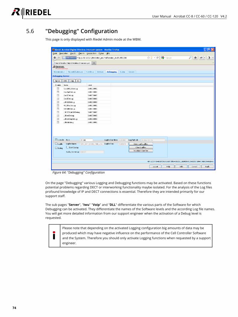
User Manual Acrobat CC-8 / CC-60 / CC-120 V4.2
74
5.6 "Debugging" Configuration This page is only displayed with Riedel Admin mode at the WBM.
Figure 64: "Debugging" Configuration
On the page "Debugging" various Logging and Debugging functions may be activated. Based on these functions potential problems regarding DECT or interworking functionality maybe isolated. For the analysis of the Log files profound knowledge of IP and DECT connections is essential. Therefore they are intended primarily for our support staff. The sub pages "Server", "Iwu" "Voip" and "DLL" differentiate the various parts of the Software for which Debugging can be activated. They differentiate the names of the Software levels and the according Log file names. You will get more detailed information from our support engineer when the activation of a Debug level is requested.
Please note that depending on the activated Logging configuration big amounts of data may be produced which may have negative influence on the performance of the Cell Controller Software and the System. Therefore you should only activate Logging functions when requested by a support engineer.
User Manual Acrobat CC-8 / CC-60 / CC-120 V4.2
75
The options of the table have the following meaning: Disable (Default value: Deactivated) When activating this entry the logging functionality for the selected entry is disabled, independent of the configured Debug level. Name (fixed) Preconfigured descriptive name of the Software level for which the Debug level is valid. You will get more detailed information from our support engineer when the activation of a Debug level is requested. Level (Default value: "0x00000000") Debug level of the selected entry. The value may be entered directly hexadecimal or via the checkboxes on the right. The options of the lower part of the configuration page have the following meaning: Console (Checkbox and entry) By activating this entry the Debugging functionality via the Console application is enabled. The entry contains the associated UDP port number for Remote Debugging. Logfile By activating this entry the Debug output is written to the associated Log files. You may choose exclusively between Option Logfile or Syslog. Logfilename This entry shows the name format of the Log file created. Syslog By activating this entry the Debug output is written to the associated Sylog server. You may choose exclusively between Option Logfile or Syslog. Debugging messages are logged to a configurable syslog daemon with Facility="LOCAL1" and SEVERTIY Level="ALERT". Syslog Server IP The IP address of the syslog server is configured here. Logfile Size Total Displays the limit of the maximum allocated disk space in bytes for all log files (stored in the "Log Path") here. A process checks periodically if the total size is reached. If the limit is reached the oldest Log Files are deleted to free up disk space. Logfile Size Displays the limit of the maximum file size in bytes of a single logfile here. As soon as this size is reached the log output is continued in a new file. LogPath All Displays the LogPath the files are stored on the Cell Controller.
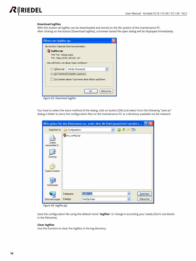
User Manual Acrobat CC-8 / CC-60 / CC-120 V4.2
76
Download logfiles With this button all logfiles can be downloaded and stored on the file system of the maintenance PC. After clicking on the button [Download logfiles], a browser based file open dialog will be displayed immediately.
Figure 65: Download logfiles
You have to select the store method of the dialog, click on button [OK] and select from the following "save as" dialog a folder to store the configuration files on the maintenance PC or a directory available via the network.
Figure 66: logfiles.tgz
Save the configuration file using the default name "logfiles" or change it according your needs (Don’t use blanks in the filename). Clear logfiles Use this function to clear the logfiles in the log directory.
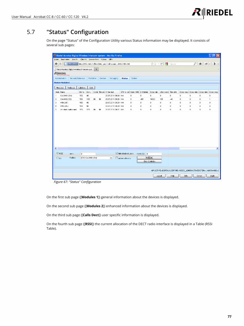
User Manual Acrobat CC-8 / CC-60 / CC-120 V4.2
77
5.7 "Status" Configuration On the page "Status" of the Configuration Utility various Status information may be displayed. It consists of several sub pages:
Figure 67: "Status" Configuration
On the first sub page ([Modules 1]) general information about the devices is displayed. On the second sub page ([Modules 2]) enhanced information about the devices is displayed. On the third sub page ([Calls Dect]) user specific information is displayed. On the fourth sub page ([RSSI]) the current allocation of the DECT radio interface is displayed in a Table (RSSI Table).
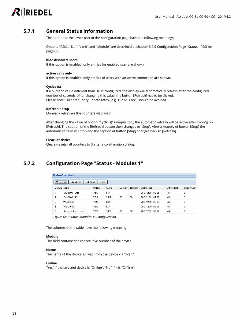
User Manual Acrobat CC-8 / CC-60 / CC-120 V4.2
78
5.7.1 General Status Information The options at the lower part of the configuration page have the following meanings: Options "RSSI", "Db", "Limit" and "Module" are described at chapter 5.7.5 Configuration Page "Status - RSSI"on page 85. hide disabled users If this option is enabled, only entries for enabled user are shown. active calls only If this option is enabled, only entries of users with an active connection are shown. Cycles (s) If a numeric value different than "0" is configured, the display will automatically refresh after the configured number of seconds. After changing this value, the button [Refresh] has to be clicked. Please note: High frequency update rates ( e.g. 1, 2 or 3 sec.) should be avoided. Refresh / Stop Manually refreshes the counters displayed. After changing the value of option "Cycle (s)" unequal to 0, the automatic refresh will be active after clicking on [Refresh]. The caption of the [Refresh] button then changes to "Stop]. After a reapply of button [Stop] the automatic refresh will stop and the caption of button [Stop] changes back to [Refresh]. Clear Statistics Clears (resets) all counters to 0 after a confirmation dialog.
5.7.2 Configuration Page "Status - Modules 1"
Figure 68: "Status-Modules 1" Configuration
The columns of the table have the following meaning: Module This field contains the consecutive number of the device. Name The name of the device as read from the device via "Scan". Online "Yes" if the selected device is "Online", "No" if it is "Offline".
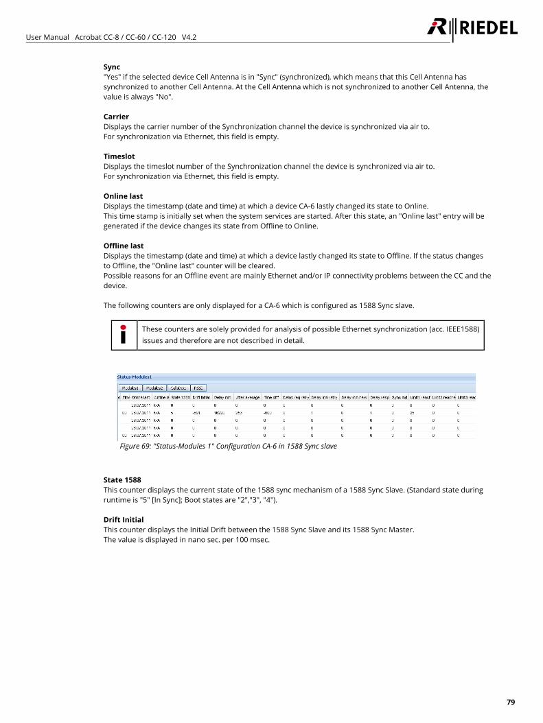
User Manual Acrobat CC-8 / CC-60 / CC-120 V4.2
79
Sync "Yes" if the selected device Cell Antenna is in "Sync" (synchronized), which means that this Cell Antenna has synchronized to another Cell Antenna. At the Cell Antenna which is not synchronized to another Cell Antenna, the value is always "No". Carrier Displays the carrier number of the Synchronization channel the device is synchronized via air to. For synchronization via Ethernet, this field is empty. Timeslot Displays the timeslot number of the Synchronization channel the device is synchronized via air to. For synchronization via Ethernet, this field is empty. Online last Displays the timestamp (date and time) at which a device CA-6 lastly changed its state to Online. This time stamp is initially set when the system services are started. After this state, an "Online last" entry will be generated if the device changes its state from Offline to Online. Offline last Displays the timestamp (date and time) at which a device lastly changed its state to Offline. If the status changes to Offline, the "Online last" counter will be cleared. Possible reasons for an Offline event are mainly Ethernet and/or IP connectivity problems between the CC and the device. The following counters are only displayed for a CA-6 which is configured as 1588 Sync slave.
These counters are solely provided for analysis of possible Ethernet synchronization (acc. IEEE1588) issues and therefore are not described in detail.
Figure 69: "Status-Modules 1" Configuration CA-6 in 1588 Sync slave
State 1588 This counter displays the current state of the 1588 sync mechanism of a 1588 Sync Slave. (Standard state during runtime is "5" [In Sync]; Boot states are "2","3", "4"). Drift Initial This counter displays the Initial Drift between the 1588 Sync Slave and its 1588 Sync Master. The value is displayed in nano sec. per 100 msec.
User Manual Acrobat CC-8 / CC-60 / CC-120 V4.2
80
Delay min This counter displays the minimum sync delay (in nano sec.) of the current 1588 Sync Slave to its 1588 Sync Master. This value corresponds to the one-way delay time of a 1588 Sync Slave to its 1588 Sync Master between all switch hops. More number of switch hops between a 1588 Sync Slave and its 1588 Sync Master will increase this value. Jitter average This counter displays the average jitter (in nano sec.) of the current 1588 Sync Slave to its 1588 Sync Master. Time diff This counter displays the current time difference or offset (in nano sec.) of the current 1588 Sync Slave to its 1588 Sync Master. Delay req retry This counter displays how often an incomplete DELAY_REQ cycle was detected. Delay min retry This counter displays how often a retry to gather the absolute time difference was established. Delay min new This counter displays how often a retry to gather the absolute time difference with a new calculated Delay min window was established. Delay resp miss This counter displays how often a missing DELAY_RESP message was detected. Sync ind miss This counter displays how often a missing SYNC_IND message was detected. Limit1 reached This counter displays how often a short term absolute time difference in a range smaller than 1000 nano sec. was detected. Limit2 reached This counter displays how often a short term absolute time difference in a range between 1000 and 5000 nano sec was detected. Limit3 reached This counter displays how often a short term absolute time difference in a range between 5000 and 20000 nano sec. was detected. If this period was detected over a time period of longer than 50 seconds, the 1588 Slave will go OutOfSync and a resynchronization process for this CA-6 will be initiated.
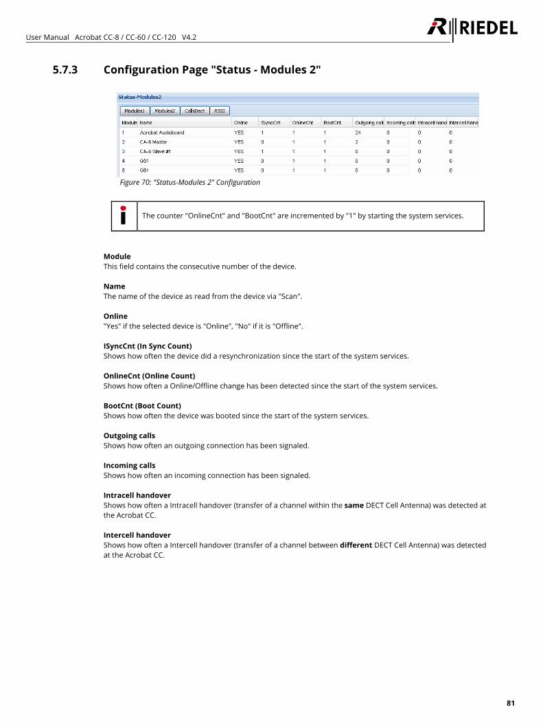
User Manual Acrobat CC-8 / CC-60 / CC-120 V4.2
81
5.7.3 Configuration Page "Status - Modules 2"
Figure 70: "Status-Modules 2" Configuration
The counter "OnlineCnt" and "BootCnt" are incremented by "1" by starting the system services.
Module This field contains the consecutive number of the device. Name The name of the device as read from the device via "Scan". Online "Yes" if the selected device is "Online", "No" if it is "Offline". ISyncCnt (In Sync Count) Shows how often the device did a resynchronization since the start of the system services. OnlineCnt (Online Count) Shows how often a Online/Offline change has been detected since the start of the system services. BootCnt (Boot Count) Shows how often the device was booted since the start of the system services. Outgoing calls Shows how often an outgoing connection has been signaled. Incoming calls Shows how often an incoming connection has been signaled. Intracell handover Shows how often a Intracell handover (transfer of a channel within the same DECT Cell Antenna) was detected at the Acrobat CC. Intercell handover Shows how often a Intercell handover (transfer of a channel between different DECT Cell Antenna) was detected at the Acrobat CC.
User Manual Acrobat CC-8 / CC-60 / CC-120 V4.2
82
Roaming This counter displays how often a roaming event (change of a Cell Antenna without an active connection) was detected at the CA-6.
Handover events (Intercell handover during an active call) are not considered by this counter. These events are handles by counter "Intercell handover".
Ovl 70 This counter displays how often the CA-6 has allocated equal or more than 70 % of the available channels. This counter doesn't consider the separation into equal and odd timeslots. For a standard configuration of a CA-6 with 12 calls (see configuration option "NumOfChannel" at chapter 5.5.1 Configuration Page "Devices - Base" on page 63) per CA-6 the counter is triggered if 9 calls are active on the DECT side. Ovl 100 This counter displays how often the CA-6 has allocated 100 % of the available channels. This counter doesn't consider the separation into equal and odd timeslots. For a standard configuration of a CA-6 with 12 calls (see configuration option "NumOfChannel" at chapter 5.5.1 Configuration Page "Devices - Base" on page 63) per CA-6 the counter is triggered if 12 calls are active on the DECT side.
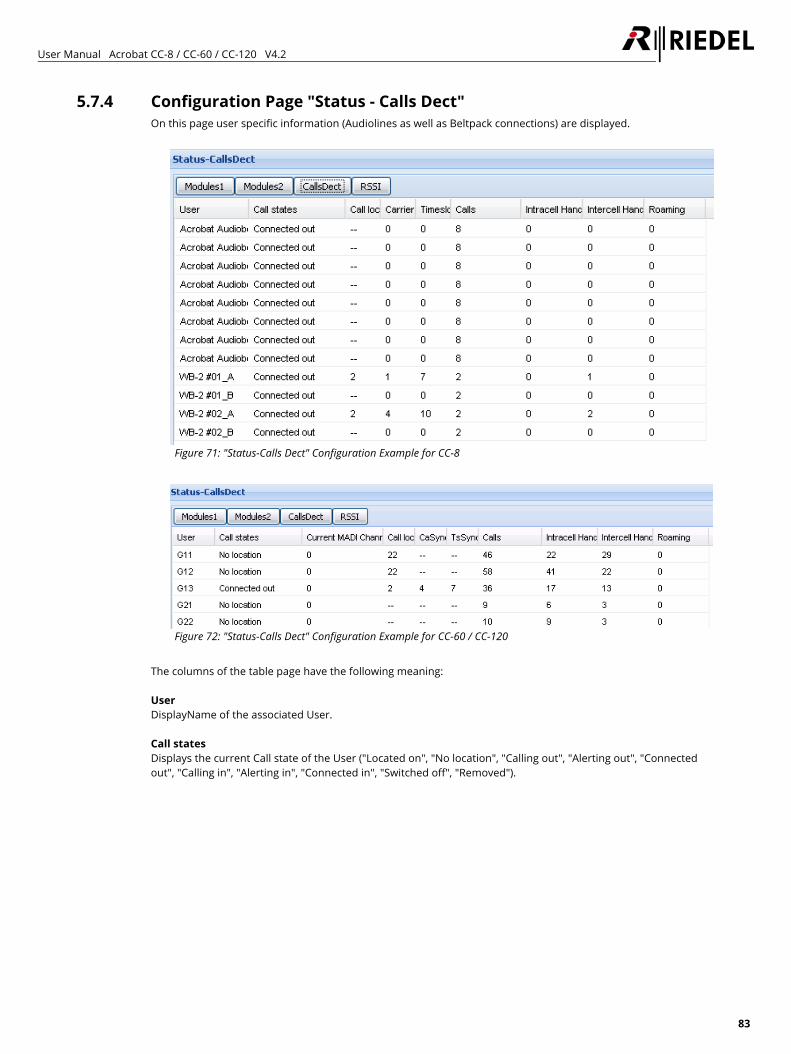
User Manual Acrobat CC-8 / CC-60 / CC-120 V4.2
83
5.7.4 Configuration Page "Status - Calls Dect" On this page user specific information (Audiolines as well as Beltpack connections) are displayed.
Figure 71: "Status-Calls Dect" Configuration Example for CC-8
Figure 72: "Status-Calls Dect" Configuration Example for CC-60 / CC-120
The columns of the table page have the following meaning: User DisplayName of the associated User. Call states Displays the current Call state of the User ("Located on", "No location", "Calling out", "Alerting out", "Connected out", "Calling in", "Alerting in", "Connected in", "Switched off", "Removed").
User Manual Acrobat CC-8 / CC-60 / CC-120 V4.2
84
Current MADI Channel (CC60/CC120) This field displays the current MADI Channel number which is assigned to the Beltpack. Normally, if the value is >0, the value is equal to the used MADI Chan. The value "0" has a special meaning (No fixed MADIChannel assignment for Beltpack, Channel not selected or Timeout expired). If a WB-2 is switched on with DIP-SW4=ON, the value will be set to "0" (Since no MADI channel may be assigned). If the Beltpack has been assigned a valid channel and the Beltpack is connected, the value will change to the number of the current used MADI Channel for this Beltpack. If the Beltpack was switched off or is not reachable, the timer (Devices > Beltpack > "Timeout") will be started. If the timer is not expired, the last MADI Chan will already be displayed. After expiration of the timer, the value will be set to "0". If a WB-2 is switched ON with DIP-SW4=OFF, the value will be set to the configured MADI Channel for this Beltpack if the channel is available. Otherwise, the value will be set to "0". After Restart of the system services, the configured MADI Channel from Devices > Audioboard > MADIChannel will be displayed here. Call located Displays the number (Index) of the Cell Antenna on which the current/last call was located on. Carrier Carrier number on which the connection for User "DisplayName" is active. Timeslot Timeslot number on which the connection for User "DisplayName" is active. Calls Number of DECT (voice) channels of the CA-6. The maximum value is "12". If less than "12" parallel voice channels shall be supported, a smaller value may be configured here. The default value is "12". Intracell handover Shows how often a Intracell handover (transfer of a channel within the same DECT Cell Antenna) was detected at the Acrobat CC. Intercell handover Shows how often a Intercell handover (transfer of a channel between different DECT Cell Antenna) was detected at the Acrobat CC. Roaming This counter displays how often a roaming event (change of a Cell Antenna without an active connection) was established for the current Beltpack.
Handover events (Intercell handover during an active call) are not considered by this counter. These events are handles by counter "Intercell handover".
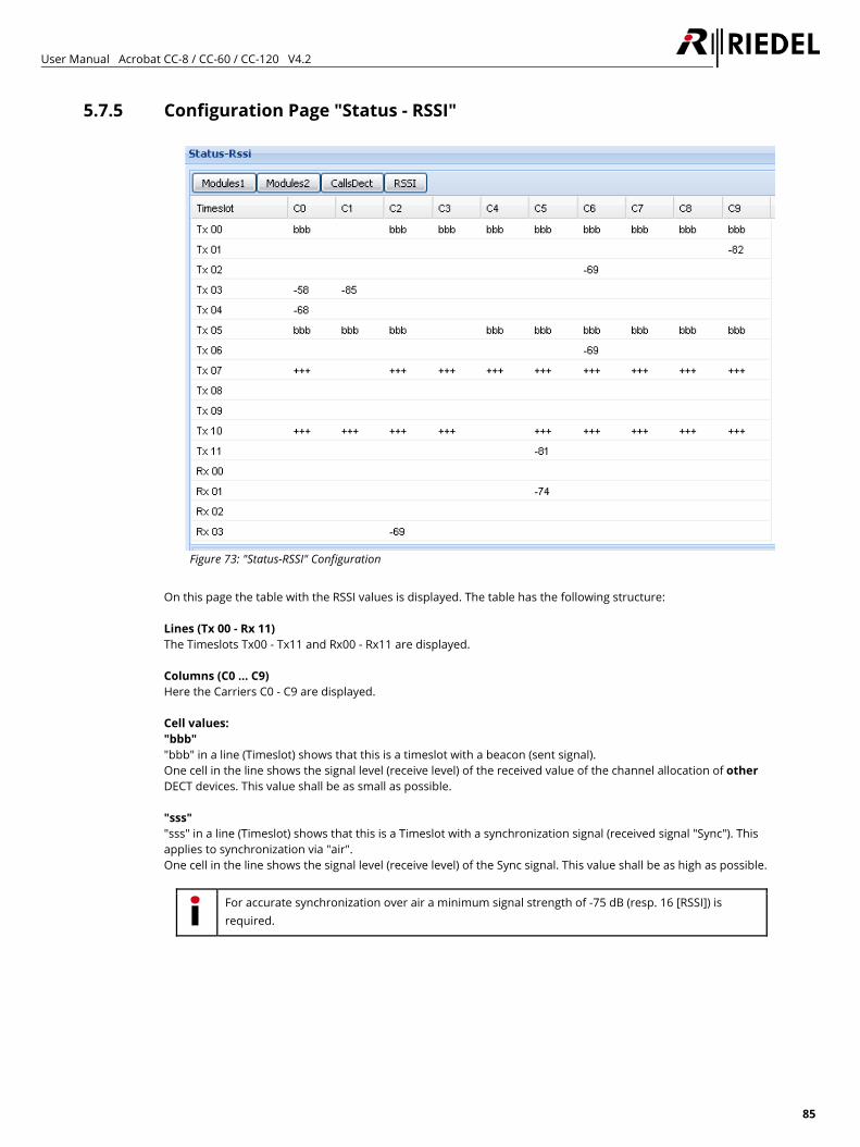
User Manual Acrobat CC-8 / CC-60 / CC-120 V4.2
85
5.7.5 Configuration Page "Status - RSSI"
Figure 73: "Status-RSSI" Configuration
On this page the table with the RSSI values is displayed. The table has the following structure: Lines (Tx 00 - Rx 11) The Timeslots Tx00 - Tx11 and Rx00 - Rx11 are displayed. Columns (C0 … C9) Here the Carriers C0 - C9 are displayed. Cell values: "bbb" "bbb" in a line (Timeslot) shows that this is a timeslot with a beacon (sent signal). One cell in the line shows the signal level (receive level) of the received value of the channel allocation of other DECT devices. This value shall be as small as possible. "sss" "sss" in a line (Timeslot) shows that this is a Timeslot with a synchronization signal (received signal "Sync"). This applies to synchronization via "air". One cell in the line shows the signal level (receive level) of the Sync signal. This value shall be as high as possible.
For accurate synchronization over air a minimum signal strength of -75 dB (resp. 16 [RSSI]) is required.
User Manual Acrobat CC-8 / CC-60 / CC-120 V4.2
86
"+++" "+++" in a line (Timeslot) shows that this is a Timeslot with a voice channel (unidirectional) signal (the Timeslot number of the Rx channel is Tx Channel + 12). One cell in a "Tx" line shows the value of the used Carrier for the voice channel. One cell in a "Rx" line shows the receive level of the Cell Antenna in relation to the active call. "<value>" Shows the current value (Receive resp. Send signal of the Rx resp. Tx Timeslot) depending on the configuration of "RSSI", "Db" and "Limit". Value ranges: minimal value (corresponds to poor reception quality): -85 dB (resp. 9 [RSSI]) maximum value (corresponds to good reception quality): -50 dB (resp. 31 [RSSI]) Values outside a “bbb”, “sss”, or “+++” line display the signal level (receive level) of other DECT devices. The number of values as well as their value itself shall be as small as possible. The options at the lower part of the configuration page have the following meanings: "RSSI" The values displayed in the RSSI table are RSSI values. "Db" The values displayed in the RSSI table are Db values. "Limit" Here you can configure a minimum value. Only values bigger (in the case of "Db" only values smaller) than "Limit" are displayed in the RSSI table. Normally the following default values are used: RSSI: "9" Db: "-85" "Module " Here you may select the Cell Antenna which values are displayed at the table.
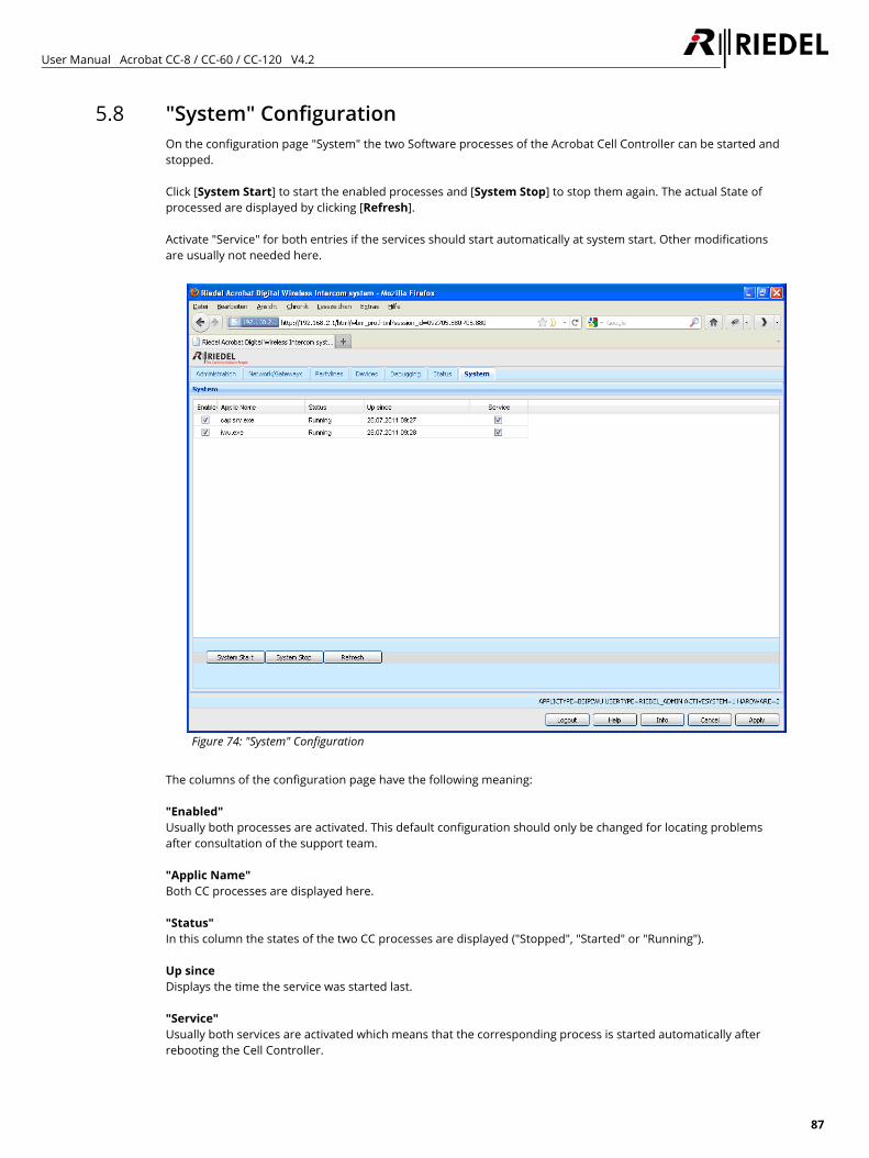
User Manual Acrobat CC-8 / CC-60 / CC-120 V4.2
87
5.8 "System" Configuration On the configuration page "System" the two Software processes of the Acrobat Cell Controller can be started and stopped. Click [System Start] to start the enabled processes and [System Stop] to stop them again. The actual State of processed are displayed by clicking [Refresh]. Activate "Service" for both entries if the services should start automatically at system start. Other modifications are usually not needed here.
Figure 74: "System" Configuration
The columns of the configuration page have the following meaning: "Enabled" Usually both processes are activated. This default configuration should only be changed for locating problems after consultation of the support team. "Applic Name" Both CC processes are displayed here. "Status" In this column the states of the two CC processes are displayed ("Stopped", "Started" or "Running"). Up since Displays the time the service was started last. "Service" Usually both services are activated which means that the corresponding process is started automatically after rebooting the Cell Controller.
User Manual Acrobat CC-8 / CC-60 / CC-120 V4.2
88
6 Configuration techniques and technologies
6.1 Technologies 6.1.1 CC-60/CC-120 MADI Channel assignment
For Acrobat CC-60/CC-120 systems, each WB-2 has to be assigned a MADI Channel. This may be accomplished by using one of two different technologies.
6.1.1.1 MADI Channel assignment by Administator (WBM) This method may be used if the Administrator of the Acrobat system is responsible for the assignment of MADI channels to Beltpacks. To activate this method, DIP-SW4 at the Beltpack has to be set to OFF and a MADI channel has to be assigned by WBM (page Devices > Beltpack > "MadiChannelNo").
6.1.1.2 MADI Channel assignment at WB-2 by User This method may be used if the Beltpack users are responsible for the assignment of a MADI channel to their Beltpack. To activate this method, DIP-SW4 at the Beltpack has to be set to ON and a MADI channel has to be assigned by using the WB-2 service menu “MADIChan”.
6.1.1.3 General
6.1.1.3.1 Formal description of WB-2 boot phase 1. Pre-condition: WB-2 was registered successfully and is operational, system services are running, WB-2 is switched OFF. WB-2 is being switched ON or is reentering the DECT area. 2. WB-2 is signaling its DIP-SW4 state to the Cell Controller. 3. Cell Controller checks if last assigned MADIChannel of the WB-2 is free (ChanAvailable) or occupied by another WB-2 (ChanOccupied) or not configured (NoChanConfigured). 4. Cell Controller sends the assigned MADIChannelNo and its current state (ChanAvailable, ChanOccupied, NoChanConfigured) back to the WB-2. 5.1 ChanAvailable The Beltpack will be started directly with OperatingDisplay. Available chans are those who are enabled and are not connected to a MADI channel. 5.2 ChanOccupied The Beltpack will be started with display message ChanOccupied and stays connected by DECT. 5.3 NoChanConfigured The Beltpack will be started with display message NoChanConfigured.
User Manual Acrobat CC-8 / CC-60 / CC-120 V4.2
89
6.1.1.4 Implementation of DIP SW 4 The Status of DIP SW 4 is needed for two issues: 1. If set to ON, the service menu "MADIChannel" is available, otherwise this service menu is not available 2. If set to ON, the timeout detection for the Beltpack at the CC will be enabled. In this case, if a MADI channel is configured for the Beltpack, this channel is reserved for this Beltpack for a period of time (see parameter Devices > Beltpack > "Timeout") after the channel was disconnected (e.g. WB-2 was switched OFF, out of DECT area, …). Keep in mind, that this channel is not exclusively reserved for the Beltpack. Another WB-2 may occupy this channel during the timeout period. If set to OFF, no Timer will be used for a Beltpack which channel is disconnected for different reasons (e.g. WB-2 was switched OFF, out of DECT area, …) -> see parameter Devices > Beltpack > Timeout.
Further details may be found in the User Manual of WB-2.
6.1.1.4.1 Hints Under normal conditions (DIP-SW4 of all WB-2 are configured uniquely, Channels are assigned uniquely to Beltpacks) all WB-2 will retrieve a “ChannelState” which will result to a functional WB-2. IF DIP-SW4 is set to OFF at all WB-2, all WB-2 will receive a “ChanAvailable”. IF DIP-SW4 is set to ON at all WB-2, the WB-2 will receive a “ChanAvailable”, “ChanOccupied” or “NoChanConfigured”. Mixing the DIP4 mode may lead to situations where a WB-2 (with DIP-SW4 set to OFF) may have no system functionality after Power-ON. In this case the DIP-mode for this WB-2 has to be set to ON or a valid channel has to be assigned at the WBM.
6.1.2 SNMP SNMP (Simple Network Management Protocol) is used by the ACROBAT system mainly to detect overload situations and failure situations of the system. These may be queried by a SNMP Server (SNMP MIB - Management Information Base) or may be signaled by the Cell Controller via SNMP Trap. Furthermore, the MIBs and traps of the OS (LINUX - openwrt) may be used - but are provided "as is". The implementation uses SNMP version 2 with fixed ports. For the ACROBAT system, a specific MIB file is available. The name of the used MIB is "ACROBAT-MIB". The Cell Controller of the Acrobat system provides besides SNMP values and tables (which may be queried with a SNMP manager) also SNMP traps which are signaled to a SNMP management system (which IP address has to be configured in the WBM of the Cell Controller). Since a lot of data has to be queried by the Cell Controller for each SNMP request, this will lead to a high system load of the Cell Controller, a special mechanism was implemented to refresh the tables only if needed. Therefore, a specific SNMP value has to be queried by the SNMP management system to trigger the actualization of the SNMP tables by the Cell Controller.
User Manual Acrobat CC-8 / CC-60 / CC-120 V4.2
90
6.1.3 SNMP - Configuration Options Page Network / Gateways SNMP Server IP Using this option, an IP address of a SNMP server may be configured here to which SNMP traps are being send.
The SNMP Server has to be located inside the Infrastructure Network.
6.1.4 Implementation Details The SNMP MIBs provide statistical data of the Cell Controller (one table per day) to retrieve them by SNMP queries. A maximum of 14 statistical tables for the last 14 days are stored. Therefore one table holds the data for the current time period (current day), the other tables provide data for the last 13 days. The naming conventions of the SNMP values according the OID (Object Identifier) is composed as follows: The table with the current period of time is assigned the relative OID .1. The table of the last day is assigned the relative OID .2. The table of the day before yesterday is assigned the relative OID .3, …
6.1.5 SNMP MIB tree The "Root-OID" is assigned the OID 1.3.6.1.4.1.36378. All ACROBAT-MIBS are located below the OID {Root-OID}.1.n
6.1.5.1 SNMP Table definition
Value Type Description From Text Date/time/reason of start of the current MIB table
To Text Date/time/reason of stop of the current MIB table
RPN Text RPN of the associated Device (if applicable)
MAC Text MAC address of the associated Device (if applicable)
Name Text Name of the associated Device
OVL70 Text This counter indicates how often 70% or more of the available channels of the associated CA-6 had been occupied. 1)
OVL100 Text This counter indicates how often 100% of the available channels of the associated CA-6 had been occupied 1)
Roaming Text This counter indicates how often a roaming process (location event of a handset without an active connection) have been indicated at the associated CA-6. 2)
1) These counters were developed for normal telephony scenarios and don't consider the separation into equal and odd timeslots. 2) This counter was developed for normal telephony scenarios and is without effect in the ACROBAT system.
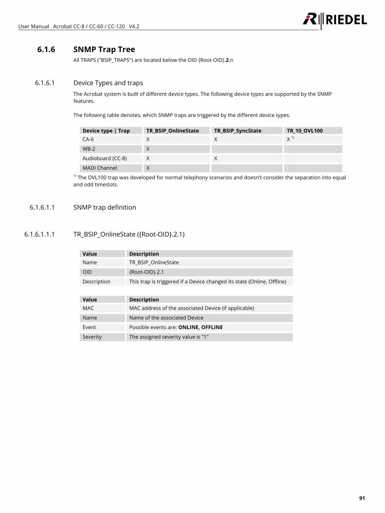
User Manual Acrobat CC-8 / CC-60 / CC-120 V4.2
91
6.1.6 SNMP Trap Tree All TRAPS ("BSIP_TRAPS") are located below the OID {Root-OID}.2.n
6.1.6.1 Device Types and traps The Acrobat system is built of different device types. The following device types are supported by the SNMP features. The following table denotes, which SNMP traps are triggered by the different device types.
Device type | Trap TR_BSIP_OnlineState TR_BSIP_SyncState TR_10_OVL100 CA-6 X X X 1)
WB-2 X
Audioboard (CC-8) X X
MADI Channel X 1) The OVL100 trap was developed for normal telephony scenarios and doesn't consider the separation into equal and odd timeslots.
6.1.6.1.1 SNMP trap definition
6.1.6.1.1.1 TR_BSIP_OnlineState ({Root-OID}.2.1)
Value Description Name TR_BSIP_OnlineState
OID {Root-OID}.2.1
Description This trap is triggered if a Device changed its state (Online, Offline)
Value Description MAC MAC address of the associated Device (if applicable)
Name Name of the associated Device
Event Possible events are: ONLINE, OFFLINE
Severity The assigned severity value is "1"
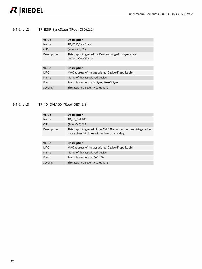
User Manual Acrobat CC-8 / CC-60 / CC-120 V4.2
92
6.1.6.1.1.2 TR_BSIP_SyncState ({Root-OID}.2.2)
Value Description Name TR_BSIP_SyncState
OID {Root-OID}.2.2
Description This trap is triggered if a Device changed its sync state (InSync, OutOfSync)
Value Description MAC MAC address of the associated Device (if applicable)
Name Name of the associated Device
Event Possible events are: InSync, OutOfSync
Severity The assigned severity value is "2"
6.1.6.1.1.3 TR_10_OVL100 ({Root-OID}.2.3)
Value Description Name TR_10_OVL100
OID {Root-OID}.2.3
Description This trap is triggered, if the OVL100 counter has been triggered for more than 10 times within the current day.
Value Description MAC MAC address of the associated Device (if applicable)
Name Name of the associated Device
Event Possible events are: OVL100
Severity The assigned severity value is "3"
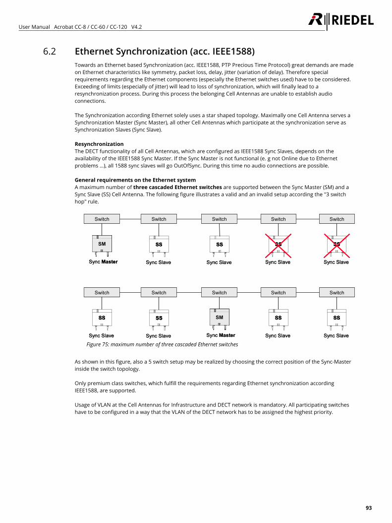
User Manual Acrobat CC-8 / CC-60 / CC-120 V4.2
93
6.2 Ethernet Synchronization (acc. IEEE1588) Towards an Ethernet based Synchronization (acc. IEEE1588, PTP Precious Time Protocol) great demands are made on Ethernet characteristics like symmetry, packet loss, delay, jitter (variation of delay). Therefore special requirements regarding the Ethernet components (especially the Ethernet switches used) have to be considered. Exceeding of limits (especially of jitter) will lead to loss of synchronization, which will finally lead to a resynchronization process. During this process the belonging Cell Antennas are unable to establish audio connections. The Synchronization according Ethernet solely uses a star shaped topology. Maximally one Cell Antenna serves a Synchronization Master (Sync Master), all other Cell Antennas which participate at the synchronization serve as Synchronization Slaves (Sync Slave). Resynchronization The DECT functionality of all Cell Antennas, which are configured as IEEE1588 Sync Slaves, depends on the availability of the IEEE1588 Sync Master. If the Sync Master is not functional (e. g not Online due to Ethernet problems …), all 1588 sync slaves will go OutOfSync. During this time no audio connections are possible. General requirements on the Ethernet system A maximum number of three cascaded Ethernet switches are supported between the Sync Master (SM) and a Sync Slave (SS) Cell Antenna. The following figure illustrates a valid and an invalid setup according the "3 switch hop" rule.
Switch Switch Switch SwitchSwitch
Sync Slave
SS
Sync Slave
SSSS
Sync Master
SM
Sync Master
SMSM
Sync Slave
SS
Sync Slave
SSSS
Sync Slave
SS
Sync Slave
SSSS
Sync Slave
SS
Sync Slave
SSSS
Switch Switch Switch SwitchSwitch
Sync Slave
SS
Sync Slave
SSSS
Sync Master
SM
Sync Master
SMSM
Sync Slave
SS
Sync Slave
SSSS
Sync Slave
SS
Sync Slave
SSSS
Sync Slave
SS
Sync Slave
SSSS
Figure 75: maximum number of three cascaded Ethernet switches
As shown in this figure, also a 5 switch setup may be realized by choosing the correct position of the Sync-Master inside the switch topology. Only premium class switches, which fulfill the requirements regarding Ethernet synchronization according IEEE1588, are supported. Usage of VLAN at the Cell Antennas for Infrastructure and DECT network is mandatory. All participating switches have to be configured in a way that the VLAN of the DECT network has to be assigned the highest priority.
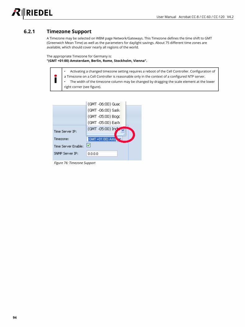
User Manual Acrobat CC-8 / CC-60 / CC-120 V4.2
94
6.2.1 Timezone Support A Timezone may be selected on WBM page Network/Gateways. This Timezone defines the time shift to GMT (Greenwich Mean Time) as well as the parameters for daylight savings. About 75 different time zones are available, which should cover nearly all regions of the world. The appropriate Timezone for Germany is: "(GMT +01:00) Amsterdam, Berlin, Rome, Stockholm, Vienna".
• Activating a changed timezone setting requires a reboot of the Cell Controller. Configuration of a Timezone on a Cell Controller is reasonable only in the context of a configured NTP server. • The width of the timezone column may be changed by dragging the scale element at the lower right corner (see figure).
Figure 76: Timezone Support
User Manual Acrobat CC-8 / CC-60 / CC-120 V4.2
95
7 Troubleshooting / FAQ
7.1 DECT
7.1.1 Cell Antenna is not found using "Scan" Please check the following: • Is the "missing" Cell Antenna connected with the network cable (LED states of the CA-6 OK)? • Is the network cable connected at a PoE Port of the CC-8? • Is the network cable connected to a PoE Ethernet Switch?
Please check the Status LEDs at the relevant PoE Ports of the Ethernet Switch. Please check if the power at the relevant PoE Port is enabled.
• Is the network cable connected to a Power Injector and an Ethernet Switch without PoE functionality? Please check the Status LEDs of the Power Injector.
• The Cell Antennas must be located in the same Ethernet segment as the Cell Controller. These devices cannot operate in different Ethernet segments connected via an IP Router.
• VLAN configuration issues • Newly added Cell Antennas are not recognized and displayed by SCAN during running system services. Stop
the system services and repeat the SCAN. • Check, if option "No new modules on scan" is activated
7.2 Audioboard at CC-8
7.2.1 No Audio data from / to Audioboard The configuration (assignment of Audiochannels / Partyline / Beltpack) is OK, but no voice from/to Audioboard may be heard at the Beltpacks. Possible reason: The Audioboard has to be in sync with the CA-6. This synchronization is done via Ethernet sync acc. IEEE 1588. If no CA-6 is configured for "1588 master", the audioboard will not be able to go "InSync".
User Manual Acrobat CC-8 / CC-60 / CC-120 V4.2
96
8 Appendix
8.1 Configuration hints for Web Browser
8.1.1 Mozilla Firefox Mozilla Firefox Versions 2.x, … 10.x are supported. Firefox versions 2.x and 3.0.x are not actively tested, but should work. The minimum supported screen resolution the Browser is running on is 1024×768.
8.1.2 Microsoft Internet Explorer The following versions of Microsoft Internet Explorer are supported: • Version 6.x • Version 7.x • Version 8.x The minimum supported screen resolution the Browser is running on is 1024x768. Depending of the security settings of MS IE, the IP address of the Cell Controller has to be added to the list of Trusted sites (Tools - Internet options - Security - Trusted sites). This comes in effect when Backing up a configuration file of the Cell Controller. If the security settings are not valid, the configuration file will not be downloaded and the WBM session will be closed. For IE7 there is an issue one some installations when backing up the configuration. After initiating the backup process, the information panel will be displayed and afterwards you are logged out from the WBM. To overcome this situation, you have to change the following settings in IE7: 1. Choose Tools – Internet-Options - Security 2. Select the appropriate zone in which the Cell Controller is located (e.g. "Trusted sites") and select [Custom
level] 3. In the outline view browse to "Downloads" and change the setting of "Automatic prompting for file
downloads" from Disabled to Enabled
IE9 is not officially supported already. The "Compatibilty mode" has to be activated; otherwise, only a blank screen will be displayed by IE9 after Login to WBM.
User Manual Acrobat CC-8 / CC-60 / CC-120 V4.2
97
9 Maintenance Recommendations Following points are strongly recommended to prevent malfunction of the system.
9.1 General • Check if all fans are running. • Check the Sync state of the Cell Antennas.
9.2 Daily None
9.3 Weekly None
9.4 Monthly • Check and set system time (if no Time Server is configured).
9.5 Yearly None
9.6 Other • Every two years all batteries should be checked for voltage.
User Manual Acrobat CC-8 / CC-60 / CC-120 V4.2
98
10 Service If you have any further questions, we offer comprehensive customer service options for this product including:
• Telephone service • E-mail service • Skype Service • Fax service • Configuration support • Trainings • Repairs
Your primary point of contact for any service issues is your local dealer. In addition, Riedel Customer Service in Wuppertal, Germany is also available to assist you.
Telephone: +49 (0) 202 292 9400 (Monday - Friday, 8am – 5pm, Central European Time) Fax: +49 (0) 202 292 9419 Skype: riedel.communications.service Or use the contact form on our website: www.riedel.net > Company > Riedel Communications > Contact > Wuppertal (Headquarters)
For repairs, please contact your local dealer. Your dealer will be able to help process your repair as fast as possible and/or arrange for the delivery of spare parts. The address for repairs sent directly to Riedel Communications GmbH is:
Riedel Communications GmbH & Co KG - Repairs - Uellendahler Str. 353 D-42109 Wuppertal Germany
Please add a completed repair form to all your repairs. The form can be found at the Riedel website: www.riedel.net > Company > Services > Support > Contact

User Manual Acrobat CC-8 / CC-60 / CC-120 V4.2
99
NOTES

www.riedel.netRiedel Communications GmbH & Co. KG | Uellendahler Str. 353 | 42109 Wuppertal | Germany