Embed Size (px)
Citation preview
USER MANUAL Evolve® 512 Delta
ii57-619-001 Rev A2 ©2016 Photometrics. All rights reserved.
Evolve® 512 Delta User Manual
© Copyright 2016 Photometrics
3440 East Britannia Drive
Tucson, Arizona 85706
Tel: +1 520.889.9933
Fax: +1 520.295.0299
All rights reserved. No part of this publication may be reproduced by any means without the written permission of
Photometrics.
Acrobat and Reader are registered trademarks of Adobe Systems Incorporated in the United States and/or other countries.
Photometrics, PVCAM, and Evolve are registered trademarks of Roper Scientific, Inc.
Intel Core is a trademark of Intel Corporation in the U.S. and/or other countries.
Windows is a registered trademark of Microsoft Corporation in the United States and/or other countries.
Other brand and product names are the trademarks or registered trademarks of their respective owners and manufacturers.
The information in this publication is believed to be accurate as of the publication release date. However, Photometrics does
not assume any responsibility for any consequences including any damages resulting from the use thereof. The information
contained herein is subject to change without notice. Revision of this publication may be issued to incorporate such change.
iii57-619-001 Rev A2 ©2016 Photometrics. All rights reserved.
Evolve® 512 Delta User Manual
LIMITED WARRANTY
Photometrics (“Photometrics,” us,” “we,” “our”) makes the following limited warranties. These limited warranties
extend to the original purchaser (“You”, “you”) only and no other purchaser or transferee. We have complete
control over all warranties and may alter or terminate any or all warranties at any time we deem necessary.
Basic Limited Two (2) Year Warranty
Photometrics warrants this product against substantial defects in materials and/or workmanship for a period of
up to two (2) years after shipment. During this period, Photometrics will repair the product or, at its sole option,
repair or replace any defective part without charge to you. You must deliver the entire product to the Photometrics
factory or, at our option, to a factory-authorized service center. You are responsible for the shipping costs to return
the product. International customers should contact their local Photometrics-authorized representative/distributor
for repair information and assistance, or visit our technical support page at www.photometrics.com.
Limited One (1) Year Warranty on Refurbished or Discontinued Products
Photometrics warrants, with the exception of the CCD imaging device (which carries NO WARRANTIES EXPRESS
OR IMPLIED), this product against defects in materials or workmanship for a period of up to one (1) year after
shipment. During this period, Photometrics will repair or replace, at its sole option, any defective parts, without
charge to you. You must deliver the entire product to the Photometrics factory or, at our option, a factory-
authorized service center. You are responsible for the shipping costs to return the product to Photometrics.
International customers should contact their local Photometrics representative/distributor for repair information
and assistance or visit our technical support page at www.photometrics.com
Normal Wear Item Disclaimer
Photometrics does not warrant certain items against defect due to normal wear and tear. These items include
internal and external shutters, cables, and connectors. These items carry no warranty, expressed or implied.
Vacuum Integrity Lifetime Warranty
Photometrics warrants the vacuum integrity of all our products for a period of up to sixty (60) months from the
date of shipment. We warrant that the detector head will maintain the factory-set operating temperature without
the requirement for customer pumping. Should the detector experience a Vacuum Integrity failure at anytime
within sixty (60) months from the date of delivery all parts and labor needed to restore the vacuum integrity will
be covered by us. Responsibility for shipping charges is as described above under our Basic Limited Two (2) Year
Warranty.
iv57-619-001 Rev A2 ©2016 Photometrics. All rights reserved.
Evolve® 512 Delta User Manual
Software Limited Warranty
Photometrics warrants all of our manufactured software discs to be free from substantial defects in materials and/
or workmanship under normal use for a period of one (1) year from shipment. Photometrics does not warrant that
the function of the software will meet your requirements or that operation will be uninterrupted or error free. You
assume responsibility for selecting the software to achieve your intended results and for the use and results obtained
from the software. In addition, during the one (1) year limited warranty, the original purchaser is entitled to receive
free version upgrades. Version upgrades supplied free of charge will be in the form of a download from the Internet.
Those customers who do not have access to the Internet may obtain the version upgrades on a CD ROM from our
factory for an incidental shipping and handling charge. See Item 12 in the following section of this warranty (“Your
Responsibility”) for more information.
Owner’s Manual and Troubleshooting
You should read the owner’s manual thoroughly before operating this product. In the unlikely event that you
should encounter difficulty operating this product, the owner’s manual should be consulted before contacting
the Photometrics technical support staff or authorized service representative for assistance. If you have consulted
the owner’s manual and the problem still persists, please contact the Photometrics technical support staff or our
authorized service representative. See Item 12 in the following section of this warranty (“Your Responsibility”) for
more information.
Your Responsibility
The above Limited Warranties are subject to the following terms and conditions:
You must retain your bill of sale (invoice) and present it upon request for service and repairs or provide other proof of
purchase satisfactory to Photometrics.
You must notify the Photometrics factory service center within thirty (30) days after you have taken delivery of a
product or part that you believe to be defective. With the exception of customers who claim a “technical issue” with
the operation of the product or part, all invoices must be paid in full in accordance with the terms of sale. Failure to
pay invoices when due may result in the interruption and/or cancellation of your two (2) year limited warranty and/
or any other warranty, expressed or implied.
All warranty service must be made by the Photometrics factory or, at our option, an authorized service center.
Before products or parts can be returned for service you must contact the Photometrics factory and receive a return
authorization number (RMA). Products or parts returned for service without a return authorization evidenced by an
RMA will be sent back freight collect.
These warranties are effective only if purchased from the Photometrics factory or one of our authorized
manufacturer’s representatives or distributors.
Unless specified in the original purchase agreement, Photometrics is not responsible for installation, setup, or
disassembly at the customer’s location.

v57-619-001 Rev A2 ©2016 Photometrics. All rights reserved.
Evolve® 512 Delta User Manual
Warranties extend only to defects in materials or workmanship as limited above and do not extend to any product
or part which has:
• been lost or discarded by you;
• been damaged as a result of misuse, improper installation, faulty or inadequate maintenance, or failure to follow instructions furnished by us;
• had serial numbers removed, altered, defaced, or rendered illegible;
• been subjected to improper or unauthorized repair; or
• been damaged due to fire, flood, radiation, or other “acts of God” or other contingencies beyond the control of Photometrics.
After the warranty period has expired, you may contact the Photometrics factory or a Photometrics-authorized
representative for repair information and/or extended warranty plans.
Physically damaged units or units that have been modified are not acceptable for repair in or out of warranty and
will be returned as received.
All warranties implied by state law or non-U.S. laws, including the implied warranties of merchantability and fitness
for a particular purpose, are expressly limited to the duration of the limited warranties set forth above. With the
exception of any warranties implied by state law or non-U.S. laws, as hereby limited, the forgoing warranty is
exclusive and in lieu of all other warranties, guarantees, agreements, and similar obligations of manufacturer or
seller with respect to the repair or replacement of any parts. In no event shall Photometrics’ liability exceed the cost
of the repair or replacement of the defective product or part.
This limited warranty gives you specific legal rights and you may also have other rights that may vary from state
to state and from country to country. Some states and countries do not allow limitations on how long an implied
warranty lasts, when an action may be brought, or the exclusion or limitation of incidental or consequential
damages, so the above provisions may not apply to you.
When contacting us for technical support or service assistance, please refer to the Photometrics factory of purchase,
contact your authorized Photometrics representative or reseller, or visit our technical support page at www.
photometrics.com.
U. S. Government Restricted Rights
The software and documentation are provided with Restricted Rights. Use, duplication, or disclosure by the
Government is subject to restrictions as set forth in subparagraph (c)(1)(ii) of the Rights in Technical Data and
Computer Software clause at DFARS 252.227-7013 or subparagraphs (c)(1) and (2) of the Commercial Computer
Software-Restricted Rights at 48 CFR 52.227-19, as applicable. Contractor/manufacturer is Photometrics, 3440 East
Britannia Drive, Tucson, AZ 85706.
This license is effective until terminated. It will terminate upon the conditions set forth above or if you fail to comply
with any term hereof. Upon termination, you agree that the software and accompanying materials, and all copies
thereof, will be destroyed. This agreement is governed by the laws of the State of Arizona. You acknowledge that you
have read this agreement, you understand it, you agree to be bound by its terms, and that this is the complete and
exclusive statement of the agreement between you and Photometrics regarding the software.
vi57-619-001 Rev A2 ©2016 Photometrics. All rights reserved.
Evolve® 512 Delta User Manual
vii57-619-001 Rev A2 ©2016 Photometrics. All rights reserved.
Evolve® 512 Delta User Manual
Overview ........................................................................................................................ 1About This Manual .......................................................................................................................... 1Precautions ...................................................................................................................................... 1Environmental Requirements ........................................................................................................... 2Storage Requirements ..................................................................................................................... 2Microscopes, Lenses, and Tripods ................................................................................................... 2Repairs ........................................................................................................................................... 2Cleaning ......................................................................................................................................... 2
System Installation ........................................................................................................... 3Introduction .................................................................................................................................... 3Software Compatibility Requirements ............................................................................................. 3Host Computer Requirements ......................................................................................................... 4Multiple Cameras ........................................................................................................................... 4Software Installation ....................................................................................................................... 4Installing the FireWire Interface Card ............................................................................................. 4Connecting Your Evolve 512 Delta Camera...................................................................................... 5
Technology Overview ................................................................................................... 6Introduction .................................................................................................................................... 6EMCCD Sensor Structure ................................................................................................................ 6EM Gain and Low Light Detection .................................................................................................. 6
Optimizing the EM Gain Setting ..................................................................................................... 7Tradeoffs with EM Gain .................................................................................................................. 7
Operating Features ......................................................................................................... 8Introduction .................................................................................................................................... 8Operating Frequencies .................................................................................................................... 8Gain States ..................................................................................................................................... 8Offset (Bias) ................................................................................................................................... 8Binning ........................................................................................................................................... 9Non-Overlap Mode ........................................................................................................................ 9Overlap Mode (Simultaneous Exposure-Readout) ......................................................................... 10Triggered Operation ..................................................................................................................... 11Shutter Signal Behavior ................................................................................................................. 11Trigger First Mode ........................................................................................................................ 11Strobe Mode ................................................................................................................................ 13Bulb Mode .................................................................................................................................... 14
Table of Contents
viii57-619-001 Rev A2 ©2016 Photometrics. All rights reserved.
Evolve® 512 Delta User Manual
SMART Streaming ........................................................................................................................ 15Rapid-Cal®.................................................................................................................................... 15Evolve 512 Delta Application Examples ......................................................................................... 17Application Settings Summary ....................................................................................................... 17
Troubleshooting ............................................................................................................ 18System Does Not Boot Normally ................................................................................................... 18New Hardware Found Dialog Box Does Not Appear ..................................................................... 18Images Not Displayed ................................................................................................................... 19Camera Running Too Warm ......................................................................................................... 19PVCAM Error Message Appears ................................................................................................... 19Lengthy Pauses During Imaging ................................................................................................... 19
Basic Specifications ....................................................................................................... 20Evolve 512 Delta Front/Side Views ............................................................................................... 20Camera Weight ............................................................................................................................ 20CCD Specifications ....................................................................................................................... 20Connectors .................................................................................................................................... 21Power Connector Pinout ............................................................................................................... 21I/O Connector Pinout ................................................................................................................... 22Power Supply Specifications .......................................................................................................... 23
Evolve LC with Ambient Cooler .................................................................................... 24
Index .............................................................................................................................. 25
157-619-001 Rev A2 ©2016 Photometrics. All rights reserved.
Evolve® 512 Delta User Manual
Chapter 1.
Overview
The Evolve 512 Delta User Manual is divided into five chapters. It is suggested that you
read the entire manual before operating the camera in order to ensure proper use. The
chapter contents are briefly described below.
Note: The information in these chapters applies only to the Evolve 512
Delta and is currently not applicable to any other Photometrics camera.
• System Installation — Instructions for connecting your Evolve 512 Delta camera to your computer via the Evolve FireWire interface card.
• Technology Overview —A basic overview of EMCCD camera technology and its benefits for low-light imaging.
• Operating Features — Discusses Evolve 512 Delta features and how to optimize them for speed, sensitivity, and use the different trigger modes.
• Troubleshooting — Provides answers to camera system problems.
• Basic Specifications — Provides specifications for Evolve 512 Delta system components.
Precautions The CCD and other system electronics are extremely sensitive to electrostatic discharge
(ESD). To avoid permanently damaging the system, please observe the following
precautions:
• If you are using high-voltage equipment (such as an arc lamp) with your camera system, be sure to turn the camera power on last and power the camera off first.
• Never connect or disconnect any cable while the system is powered on.
• Although you should switch off the camera’s power before disconnecting any camera system cable, you do not need to power off your computer to detach the cables.
• Use caution when triggering high-current switching devices (such as an arc lamp) near your system. The CCD can be permanently damaged by transient voltage spikes. If electrically noisy devices are present, an isolated, conditioned power line or dedicated isolation transformer is highly recommended.
• Always leave one inch of space around the camera’s external cooling fins for airflow.
About This Manual
257-619-001 Rev A2 ©2016 Photometrics. All rights reserved.
Evolve® 512 Delta User Manual
Environmental Requirements
• Never open the camera. There are no user-serviceable parts inside the Evolve 512 Delta camera. Opening the camera voids the warranty.
• Use only the FireWire interface card, cables, and power supply designated for this camera system. Using non-Evolve cables, FireWire interface cards, or power supplies may result in permanent damage to your system.
• Do not use a C-mount lens with optics that extend behind the lens flange.
Storage Requirements
Store the Evolve 512 Delta camera system in its original containers. To protect the
system from excessive heat, cold, and moisture, store at an ambient temperature
between -20°C and 60°C with a relative humidity of 0% to 90%, noncondensing.
The Evolve 512 Delta camera system should be operated in a clean, dry environment.
The camera system’s ambient operating temperature is 0°C to 30°C with 80% relative
humidity, non-condensing.
Microscopes, Lenses, and
Tripods
Repairs The Evolve 512 Delta camera system contains no user-serviceable parts. Repairs must
be done by Photometrics. Should your camera system need repair, contact Photometrics
Customer Service. Please save the original packing materials so you can safely ship the
camera system to another location or return it for repairs if necessary.
Note: Do not open the camera. Opening the Evolve 512 Delta camera
voids the warranty.
The camera has a standard threaded video mount and can be mounted to any
microscope that accepts a standard C-mount adapter. The camera also allows you to
install any lens that is compatible with a standard threaded video mount as long as its
optics do not extend behind the flange of the lens. The Evolve 512 Delta camera can be
mounted to a tripod using the tripod mounting attachment located on the sides of the
camera.
Cleaning Clean exterior surfaces of the camera with a dry, lint-free cloth. To remove stains,
contact Photometrics Customer Service. To clean the camera’s imaging window, use
only a filtered compressed-air source. Hand-held cans are not recommended, as they
may spray propellant onto the window. Do not touch the window.
357-619-001 Rev A2 ©2016 Photometrics. All rights reserved.
Evolve® 512 Delta User Manual
Chapter 2.
System Installation
Introduction Your Evolve 512 Delta camera system has the following hardware components:
• Camera head
• FireWire interface card
• Data cable
• Power supply with power cord
• USB installation drive
• Quick installation guide
Evolve 512 Delta system components are linked by the FireWire data cable and
controlled by your host computer system. All of these hardware components should be
included with your shipment. Keep all the original packing materials so you can safely
ship the Evolve 512 Delta system to another location or return it for service if necessary.
If you have any difficulty with any step of the instructions, call Photometrics Customer
Service.
Carefully review the Precautions section in the previous chapter before
performing any of the procedures outlined here. Again, use only an
Evolve data cable and an Evolve FireWire interface card with your Evolve
512 Delta camera. Using a different cable or interface card may result in
permanent damage to your system.
Software Compatibility Requirements
The Evolve 512 Delta package includes the PVCAM drivers designed to allow you
to use this camera with a variety of third party imaging software - To see a list of
supported software, visit the Photometrics website.
The latest version of PVCAM is recommended for use with the Evolve Delta software –
unless there is a preferred version required by the third party software.
457-619-001 Rev A2 ©2016 Photometrics. All rights reserved.
Evolve® 512 Delta User Manual
Host Computer Requirements
Multiple Cameras
PVCAM supports multiple open cameras. In order to use this function, it must also be
supported by your imaging software.
If your imaging software supports multiple cameras, there must be a separate Firewire
interface card for each camera.
The host computer (PC) for your Evolve 512 Delta camera must meet the following
minimum requirements:
• Windows® 7 Professional operating system
• Intel® Core™ i5 processor
• 4 GB of RAM (or greater)
• Open USB port or internet access to install the driver
• At least one PCI-Express interface slot for the FireWire interface card
Software Installation
An Installation Guide appropriate to your system is included as an insert with the
camera system. This guide provides step-by-step instructions for installing the camera
interface software and the application software for Windows-based computers.
Additional instructions are included for installing a FireWire interface card in your
computer and capturing images.
The Photometrics CD-ROM contains the following files:
• Manuals directory — contains user manuals in PDF format.
• WinOS directory — contains the files for installing on a Windows PC.
Installing the FireWire
Interface Card
You will be using an Evolve FireWire interface card to allow the camera to communicate
with your computer.
After installing the interface card, continue to Connecting Your Evolve 512 Delta
Camera.
557-619-001 Rev A2 ©2016 Photometrics. All rights reserved.
Evolve® 512 Delta User Manual
Connecting Your Evolve 512 Delta
Camera
The following connectors are located on the side of the Evolve 512 Delta camera:
• DATA connector: Type 1, 6-pin IEEE-1394a (FireWire) connector for data transfer
• POWER connector: 25-pin, Dsub connector for camera power (see POWER Connector Pinout section in Chapter 6 for details)
• Power button: Turns the camera on and off.
The following connector is located on the power supply of the Evolve 512 Delta camera:
• I/O connector: Hirose HR10A-10R-10S, 10-pin connector for hardware triggering input/output control signals (see I/O Connector Pinout, Chapter 6).
• To connect your Evolve 512 Delta camera
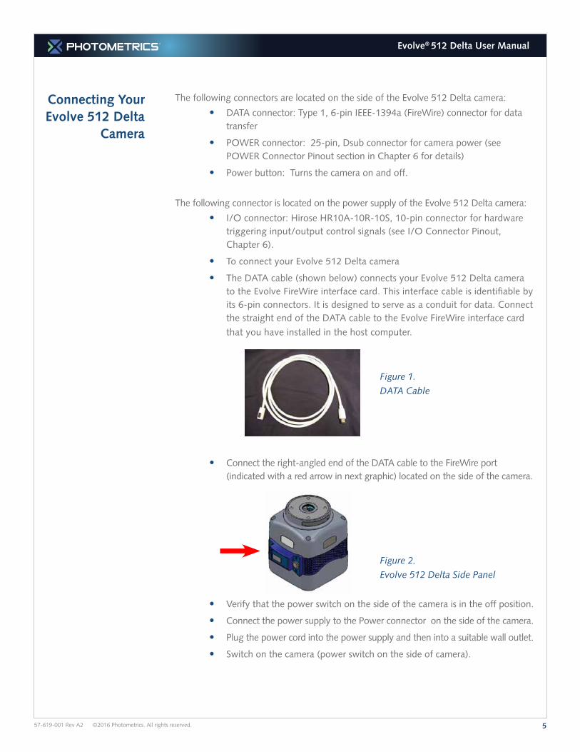
• The DATA cable (shown below) connects your Evolve 512 Delta camera to the Evolve FireWire interface card. This interface cable is identifiable by its 6-pin connectors. It is designed to serve as a conduit for data. Connect the straight end of the DATA cable to the Evolve FireWire interface card
that you have installed in the host computer.
Figure 1.
DATA Cable
• Connect the right-angled end of the DATA cable to the FireWire port (indicated with a red arrow in next graphic) located on the side of the camera.
Figure 2.
Evolve 512 Delta Side Panel
• Verify that the power switch on the side of the camera is in the off position.
• Connect the power supply to the Power connector on the side of the camera.
• Plug the power cord into the power supply and then into a suitable wall outlet.
• Switch on the camera (power switch on the side of camera).
657-619-001 Rev A2 ©2016 Photometrics. All rights reserved.
Evolve® 512 Delta User Manual
Chapter 3.
Technology Overview
EMCCD Sensor Structure
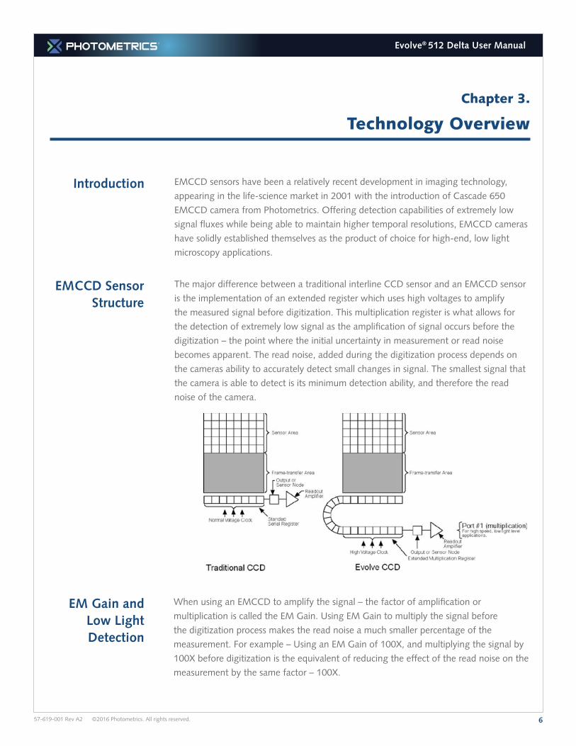
The major difference between a traditional interline CCD sensor and an EMCCD sensor
is the implementation of an extended register which uses high voltages to amplify
the measured signal before digitization. This multiplication register is what allows for
the detection of extremely low signal as the amplification of signal occurs before the
digitization – the point where the initial uncertainty in measurement or read noise
becomes apparent. The read noise, added during the digitization process depends on
the cameras ability to accurately detect small changes in signal. The smallest signal that
the camera is able to detect is its minimum detection ability, and therefore the read
noise of the camera.
EMCCD sensors have been a relatively recent development in imaging technology,
appearing in the life-science market in 2001 with the introduction of Cascade 650
EMCCD camera from Photometrics. Offering detection capabilities of extremely low
signal fluxes while being able to maintain higher temporal resolutions, EMCCD cameras
have solidly established themselves as the product of choice for high-end, low light
microscopy applications.
Introduction
EM Gain and Low Light Detection
When using an EMCCD to amplify the signal – the factor of amplification or
multiplication is called the EM Gain. Using EM Gain to multiply the signal before
the digitization process makes the read noise a much smaller percentage of the
measurement. For example – Using an EM Gain of 100X, and multiplying the signal by
100X before digitization is the equivalent of reducing the effect of the read noise on the
measurement by the same factor – 100X.
757-619-001 Rev A2 ©2016 Photometrics. All rights reserved.
Evolve® 512 Delta User Manual
Optimizing the EM Gain Setting
It has been experimentally determined that the read-noise of an EMCCD camera
asymptotically approaches ~0.2 electrons – and as such, maximizing the detection
capability of the camera depends on getting as close to this point as possible. A good
rule of thumb is to take the read noise specification for a camera – available on the
datasheet – and multiply this number by 4X or 5X and use this value as your EM Gain
setting. In most situations, an EM Gain of 350X or more is rarely required.
There are other benefits to setting the EM Gain to this value and not higher – the
reduction of clock induced charge which will show up in your images as single pixel
events or speckles, extending the performance of your EM Gain (discussed below), and
maximizing the dynamic range.
Tradeoffs with EM Gain
Using EM Gain allows for the detection of extremely low signal levels, but there are a
few tradeoffs in imaging performance that have to be made. Firstly – the multiplication
process is inherently a stochastic process and therefore there is an additional amount of
uncertainty added to your measurements due to the slightly varying nature of the EM
Gain multiplication performance. This additional uncertainty is called the Excess Noise
Factor – the amount that the shot noise affects the image are increased. This Excess
Noise Factor has experimentally been determined to be equal to √2 or ~1.4. All noise
factors (shot noise, dark current noise) except read noise are increased by this factor.
Another tradeoff is the generation of Background Events or Clock Induced Charge. Due
to the higher voltages required during the clocking of the sensor, spurious charge may
be generated along the way. Normally, this would not be an issue due to it being easily
covered up by the read noise of the sensor – but when a sensor is able to detect signals
as low as an electron – it becomes apparent in the images very quickly. By using a
lower amount of EM Gain, the amount of background events is minimized. The Evolve
platform of EMCCD cameras has been designed to keep the background events as low
as possible.
The e2V CCD97 sensor used in the Evolve 512 Delta camera has demonstrated that
over time and with extended use, the performance of the EM Gain multiplication drops.
To maintain the expected levels of performance the EM Gain needs to be recalibrated
by adjusting the voltage levels being applied to the EM Gain circuitry. The Evolve
512 Delta camera offers the fastest EM Gain calibration system on the market with
RapidCAL.
The use of EM Gain lowers the effective read noise of the camera, and brings the
minimum detection limit to the lowest possible limit. This directly correlates to the ability
to detect extremely low signal fluxes with the camera.
857-619-001 Rev A2 ©2016 Photometrics. All rights reserved.
Evolve® 512 Delta User Manual
Introduction
Operating Frequencies
The Evolve 512 Delta camera has two operating frequencies or speeds: 20MHz and
10MHz. The 20MHz speed is the most optimized, delivering the highest frame rates
while maintaining the lowest noise performance – which delivers the best Signal to
Noise imaging quality while providing the highest temporal resolution balance.
The 10MHz speed is included primarily for experimental scenarios where the temporal
resolution is not as critical and provides better noise performance than the faster speed.
This section will explain the different modes of operation for the Evolve 512 Delta,
other features, and the best modes to optimize your imaging performance.
Gain States
Offset (Bias) CCD cameras are typically designed to produce a certain level of offset (also known as
bias) when no light is present and the exposure time is set to zero (0). Typically, the
user subtracts an offset (bias) from the sample image for quantitative measurement.
Since the offset can change based on several factors such as multiplication gain, speed,
etc., it is recommended that a fresh offset (bias) image be taken with the same settings
as the sample image and then be subtracted from the sample image.
The Evolve 512 Delta has an automatically adjusting offset switch. When a speed/gain
setting is altered, the bias valve is kept as close to a pre-selected offset as possible. This
enhances the quantitative stability of the camera.
The factor of conversion of the detected signal to digital units or intensities reported by
the camera is defined as the camera’s Gain. It is defined as a ratio of electrons/ADU.
The Evolve 512 Delta has two Gain states, each offering a gain conversion factor
optimized for a different performance benefit. Gain state 1 is designed for use with 2x2
binning and offers a higher dynamic range while Gain state 2 offers better intensity
resolution and better noise performance, and is the ideal imaging mode for the majority
of applications. It is optimized to saturate the single-pixel full well of the sensor at
the maximum 16-bit intensity levels. The exact values of the conversion gains for
each camera are provided to you on a Certificate of Performance, supplied with every
camera, listing the gain, noise, and other key specifications of the camera.
Chapter 4.
Operating Features
957-619-001 Rev A2 ©2016 Photometrics. All rights reserved.
Evolve® 512 Delta User Manual
Binning Binning (combining pixels into one super pixel) allows you to increase the sensitivity and
frame rate. On the other hand, binning reduces spatial resolution. The Evolve 512 Delta
allows binning of 1x1, 2x2, 4x4, and 8x8.
Non-Overlap Mode
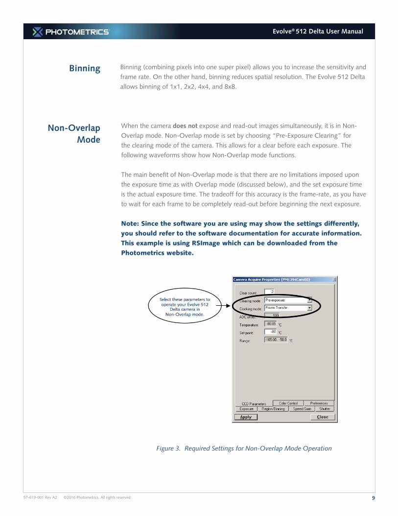
When the camera does not expose and read-out images simultaneously, it is in Non-
Overlap mode. Non-Overlap mode is set by choosing “Pre-Exposure Clearing” for
the clearing mode of the camera. This allows for a clear before each exposure. The
following waveforms show how Non-Overlap mode functions.
The main benefit of Non-Overlap mode is that there are no limitations imposed upon
the exposure time as with Overlap mode (discussed below), and the set exposure time
is the actual exposure time. The tradeoff for this accuracy is the frame-rate, as you have
to wait for each frame to be completely read-out before beginning the next exposure.
Note: Since the software you are using may show the settings differently,
you should refer to the software documentation for accurate information.
This example is using RSImage which can be downloaded from the
Photometrics website.
Figure 3. Required Settings for Non-Overlap Mode Operation
1057-619-001 Rev A2 ©2016 Photometrics. All rights reserved.
Evolve® 512 Delta User Manual
Overlap Mode (Simultaneous
Exposure-Readout)
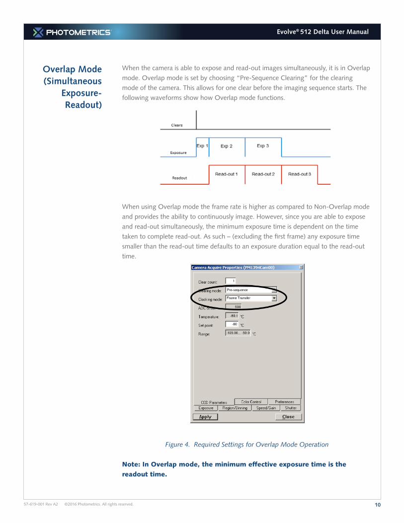
When the camera is able to expose and read-out images simultaneously, it is in Overlap
mode. Overlap mode is set by choosing “Pre-Sequence Clearing” for the clearing
mode of the camera. This allows for one clear before the imaging sequence starts. The
following waveforms show how Overlap mode functions.
When using Overlap mode the frame rate is higher as compared to Non-Overlap mode
and provides the ability to continuously image. However, since you are able to expose
and read-out simultaneously, the minimum exposure time is dependent on the time
taken to complete read-out. As such – (excluding the first frame) any exposure time
smaller than the read-out time defaults to an exposure duration equal to the read-out
time.
Figure 4. Required Settings for Overlap Mode Operation
Note: In Overlap mode, the minimum effective exposure time is the
readout time.
1157-619-001 Rev A2 ©2016 Photometrics. All rights reserved.
Evolve® 512 Delta User Manual
Triggered Operation
The Evolve 512 Delta camera offers several methods of integration with external
trigger devices, such as shutters or laser illumination sources. Each camera has a 10-
pin, Hirose HR10A I/O connector (pinout functions are described in Chapter 5) on
the power supply for trigger input/out and various TTL input and output operations. A
special cable is available from Photometrics to access primary signals such as “Trigger
input,” “Expose out,” “Frame readout,” and “Shutter out.” In the default mode, the
camera triggers on the rising edge of a TTL signal. Evolve 512 Delta cameras support
the trigger modes described in the next sections.
The types of triggering supported by the Evolve Delta cameras are:
• Trigger First Mode (Overlap/Non Overlap)
• Strobe Mode (Overlap/Non Overlap)
• Bulb Mode (Non Overlap)
• The waveform behavior is shown for the following signal:
• Trigger In
• Trigger Ready
• Camera Expose
• Read-out
Shutter Signal Behavior
There are 5 shutter behavior modes that are available:
• Open Never – Shutter is always closed.
• Open Pre-Exposure – Open before every exposure, closed when not exposing.
• Open Pre-Sequence – Open before start of sequence, closed at end of sequence
• Open Pre-Trigger – Causes shutter to open before external trigger is received. In non-triggered mode, operates as “Open Pre-Exposure”
• Open No Change – Sends no signals to open or close the shutter
Trigger First Mode
In trigger first mode, the camera requires one trigger to begin the acquisition of a
stream of images. Once the trigger is received, the camera runs using its internal timed
mode, independent of any future triggers. It is possible to run this triggering mode in
either Overlap Mode or Non-Overlap Mode.
1257-619-001 Rev A2 ©2016 Photometrics. All rights reserved.
Evolve® 512 Delta User Manual
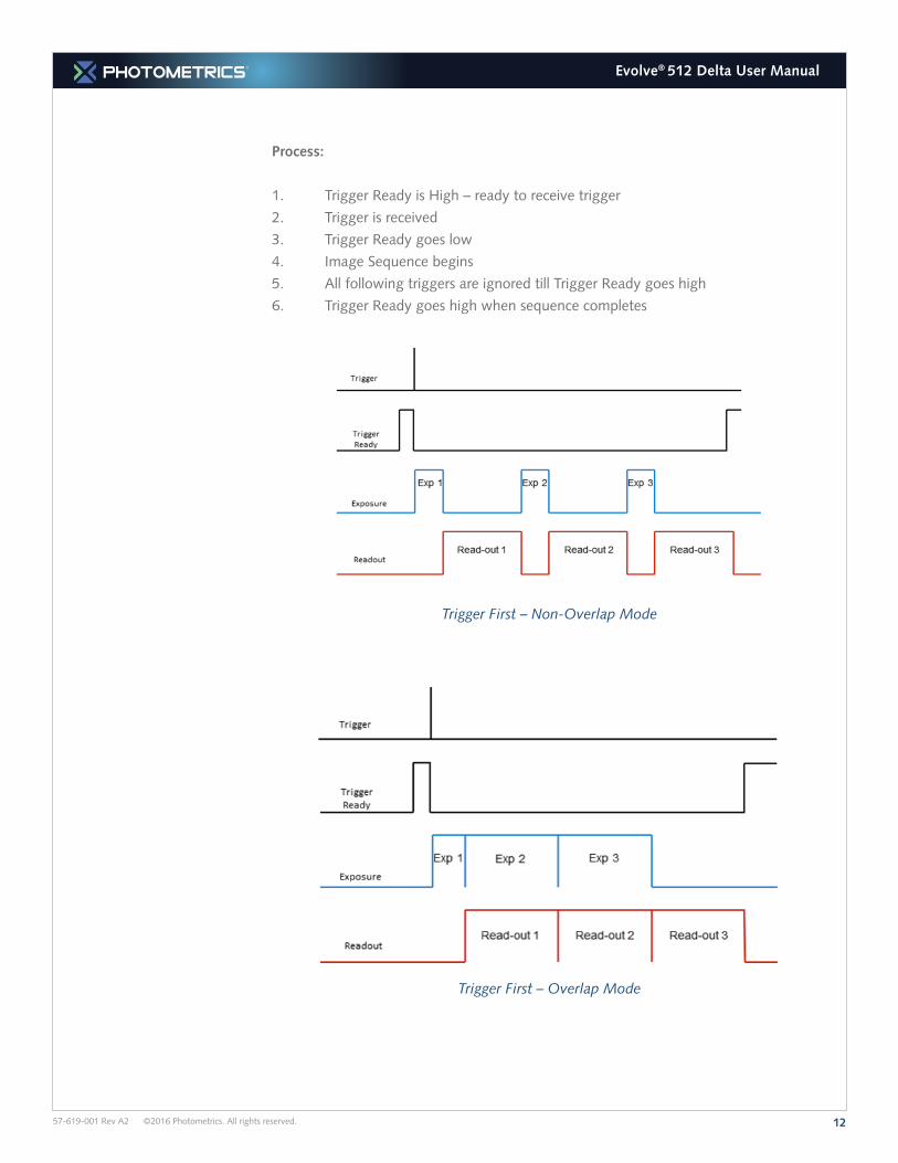
Process:
1. Trigger Ready is High – ready to receive trigger
2. Trigger is received
3. Trigger Ready goes low
4. Image Sequence begins
5. All following triggers are ignored till Trigger Ready goes high
6. Trigger Ready goes high when sequence completes
Trigger First – Non-Overlap Mode
Trigger First – Overlap Mode
1357-619-001 Rev A2 ©2016 Photometrics. All rights reserved.
Evolve® 512 Delta User Manual
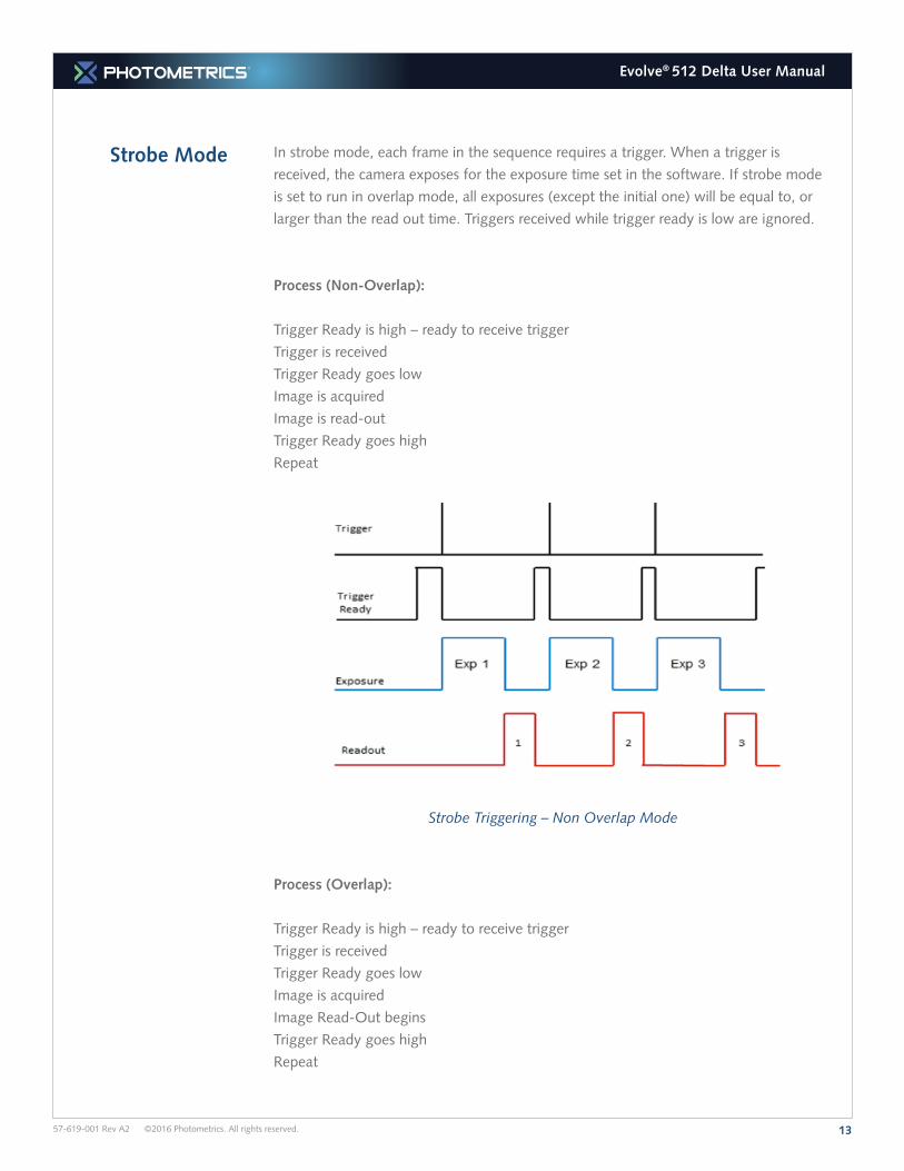
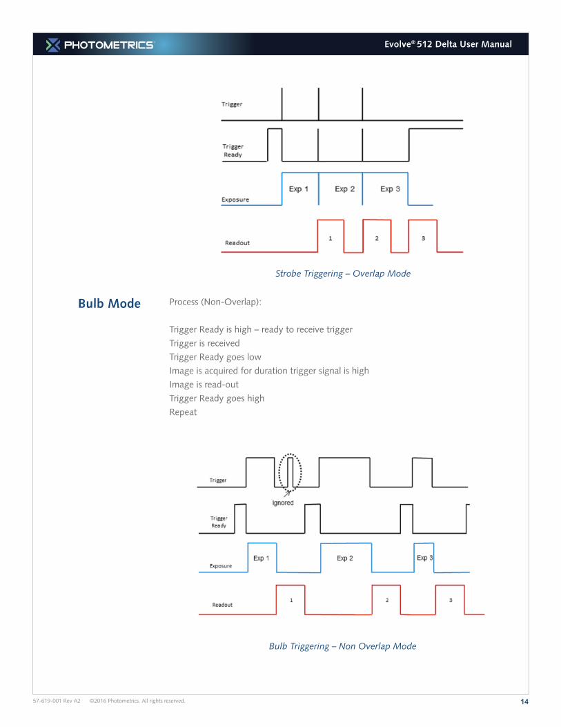
Strobe Mode In strobe mode, each frame in the sequence requires a trigger. When a trigger is
received, the camera exposes for the exposure time set in the software. If strobe mode
is set to run in overlap mode, all exposures (except the initial one) will be equal to, or
larger than the read out time. Triggers received while trigger ready is low are ignored.
Process (Non-Overlap):
Trigger Ready is high – ready to receive trigger
Trigger is received
Trigger Ready goes low
Image is acquired
Image is read-out
Trigger Ready goes high
Repeat
Strobe Triggering – Non Overlap Mode
Process (Overlap):
Trigger Ready is high – ready to receive trigger
Trigger is received
Trigger Ready goes low
Image is acquired
Image Read-Out begins
Trigger Ready goes high
Repeat
1457-619-001 Rev A2 ©2016 Photometrics. All rights reserved.
Evolve® 512 Delta User Manual
Bulb Mode Process (Non-Overlap):
Trigger Ready is high – ready to receive trigger
Trigger is received
Trigger Ready goes low
Image is acquired for duration trigger signal is high
Image is read-out
Trigger Ready goes high
Repeat
Bulb Triggering – Non Overlap Mode
Strobe Triggering – Overlap Mode
1557-619-001 Rev A2 ©2016 Photometrics. All rights reserved.
Evolve® 512 Delta User Manual
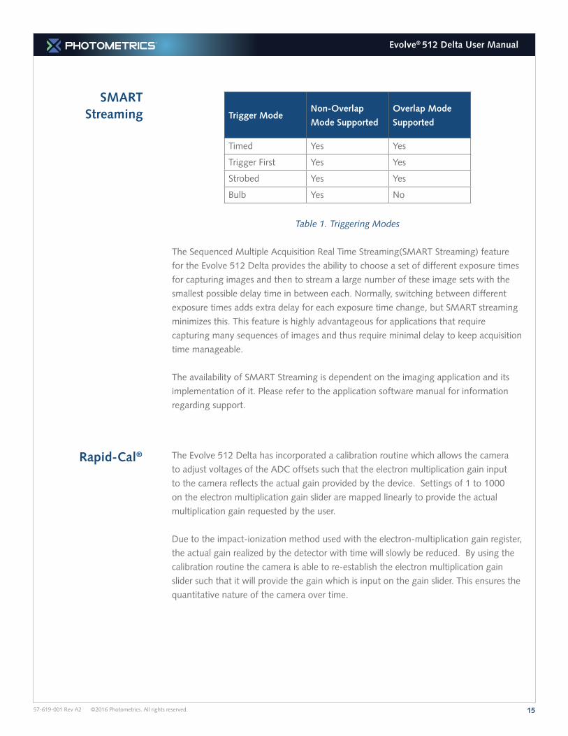
SMART Streaming Trigger Mode
Non-Overlap
Mode Supported
Overlap Mode
Supported
Timed Yes Yes
Trigger First Yes Yes
Strobed Yes Yes
Bulb Yes No
Table 1. Triggering Modes
The Sequenced Multiple Acquisition Real Time Streaming(SMART Streaming) feature
for the Evolve 512 Delta provides the ability to choose a set of different exposure times
for capturing images and then to stream a large number of these image sets with the
smallest possible delay time in between each. Normally, switching between different
exposure times adds extra delay for each exposure time change, but SMART streaming
minimizes this. This feature is highly advantageous for applications that require
capturing many sequences of images and thus require minimal delay to keep acquisition
time manageable.
The availability of SMART Streaming is dependent on the imaging application and its
implementation of it. Please refer to the application software manual for information
regarding support.
Rapid-Cal®
The Evolve 512 Delta has incorporated a calibration routine which allows the camera
to adjust voltages of the ADC offsets such that the electron multiplication gain input
to the camera reflects the actual gain provided by the device. Settings of 1 to 1000
on the electron multiplication gain slider are mapped linearly to provide the actual
multiplication gain requested by the user.
Due to the impact-ionization method used with the electron-multiplication gain register,
the actual gain realized by the detector with time will slowly be reduced. By using the
calibration routine the camera is able to re-establish the electron multiplication gain
slider such that it will provide the gain which is input on the gain slider. This ensures the
quantitative nature of the camera over time.
1657-619-001 Rev A2 ©2016 Photometrics. All rights reserved.
Evolve® 512 Delta User Manual
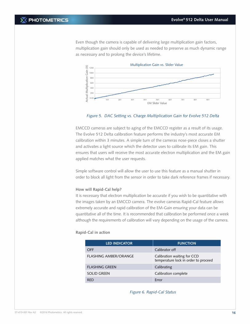
Even though the camera is capable of delivering large multiplication gain factors,
multiplication gain should only be used as needed to preserve as much dynamic range
as necessary and to prolong the device’s lifetime.
1 101 201 301 401 501 601 701 801 901
1200
1000
800
600
400
200
0.00
Act
ual M
ultip
licat
ion
Gai
n (X
) Multiplication Gain vs. Slider Value
EM Slider Value
Figure 5. DAC Setting vs. Charge Multiplication Gain for Evolve 512 Delta
EMCCD cameras are subject to aging of the EMCCD register as a result of its usage.
The Evolve 512 Delta calibration feature performs the industry’s most accurate EM
calibration within 3 minutes. A simple turn of the cameras nose-piece closes a shutter
and activates a light source which the detector uses to calibrate its EM gain. This
ensures that users will receive the most accurate electron multiplication and the EM gain
applied matches what the user requests.
Simple software control will allow the user to use this feature as a manual shutter in
order to block all light from the sensor in order to take dark reference frames if necessary.
How will Rapid-Cal help?
It is necessary that electron multiplication be accurate if you wish to be quantitative with
the images taken by an EMCCD camera. The evolve cameras Rapid-Cal feature allows
extremely accurate and rapid calibration of the EM-Gain ensuring your data can be
quantitative all of the time. It is recommended that calibration be performed once a week
although the requirements of calibration will vary depending on the usage of the camera.
Rapid-Cal in action
LED INDICATOR FUNCTION
OFF Calibrator off
FLASHING AMBER/ORANGE Calibration waiting for CCD temperature lock in order to proceed
FLASHING GREEN Calibrating
SOLID GREEN Calibration complete
RED Error
Figure 6. Rapid-Cal Status
1757-619-001 Rev A2 ©2016 Photometrics. All rights reserved.
Evolve® 512 Delta User Manual
Evolve 512 Delta Application
Examples
Example 1:
“I would like to acquire a large stack of single-molecule images to generate my
super-resolution data. My light level is fairly low and I want to optimize the frame
rate of the camera.”
For this application, select the 20MHz camera speed. In addition, the camera should
be operated in “Overlap mode”. This can be achieved by setting the camera clearing
mode to “Pre-sequence”. If desired, choose a sub-region (ROI) and/or binning to
further increase the frame rate. Finally, on-chip multiplication gain should be used at
approximately 300X to boost the signal level and achieve a high signal-to-noise ratio.
Example 2:
“My application requires precise control of the exposure time (less than the readout
time) and I want to operate the camera in the most sensitive mode possible.”
For better imaging characteristics, select the speed to be 10 MHz. Use on-chip
multiplication gain for increased sensitivity. To achieve an exposure time less than
readout time, use Non-Overlap mode and set the clearing mode to “Pre-exposure” .
Application Settings
Summary
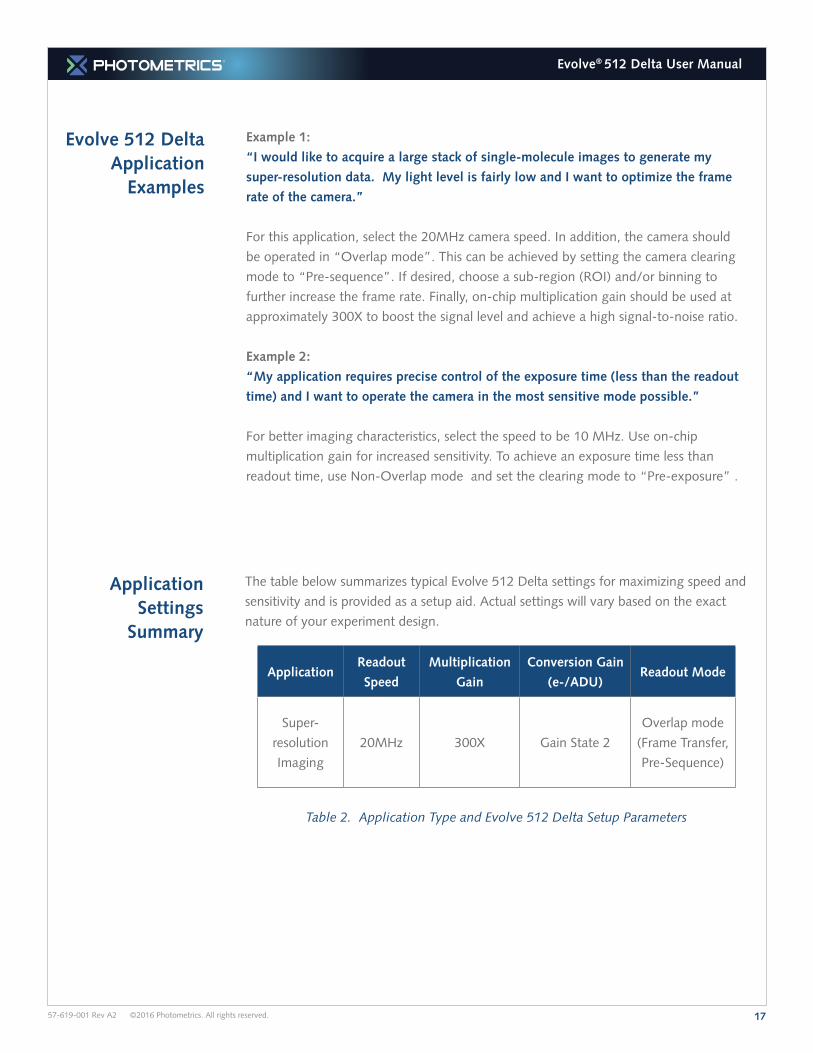
The table below summarizes typical Evolve 512 Delta settings for maximizing speed and
sensitivity and is provided as a setup aid. Actual settings will vary based on the exact
nature of your experiment design.
ApplicationReadout
Speed
Multiplication
Gain
Conversion Gain
(e-/ADU)Readout Mode
Super-
resolution
Imaging
20MHz 300X Gain State 2
Overlap mode
(Frame Transfer,
Pre-Sequence)
Table 2. Application Type and Evolve 512 Delta Setup Parameters
1857-619-001 Rev A2 ©2016 Photometrics. All rights reserved.
Evolve® 512 Delta User Manual
System Does Not Boot Normally
New Hardware Found Dialog Box Does Not
Appear
If the New Hardware Found dialog box does not appear after installing a new interface
card to your computer and booting Windows 7:
• Check to make sure that the new interface card is inserted in an expansion slot according to your computer manufacturer’s instructions and that the Evolve 512 Delta system’s CD-ROM disc is in the host computer’s CD drive.
• It is possible that there is a conflict between the new interface card and a previously installed expansion card. With the computer’s power turned off, remove any previously installed expansion cards that your system does not need to function. (If you are unsure which cards can be safely removed, call Photometrics Customer Service.) Then turn your computer back on.
• If the New Hardware Found dialog box still does not appear, contact Photometrics Customer Service.
If your operating system does not boot normally after you have installed an interface
card, try installing the new card in another open slot. If this does not work, turn off your
computer and remove the newly installed interface card. Turn your computer back on. If
your system boots normally, there is probably an interrupt conflict between a previously
installed expansion card and the interface card that you are installing. If you need
assistance resolving the interrupt conflict, contact Photometrics Customer Service.
Chapter 5.
Troubleshooting
If you have any difficulty while troubleshooting, or do not see your camera
system’s symptoms listed here, contact Photometrics Customer Service.
1957-619-001 Rev A2 ©2016 Photometrics. All rights reserved.
Evolve® 512 Delta User Manual
Images Not Displayed
Camera Running Too Warm
It is normal for the camera to be slightly warm to the touch while in operation.
However, if the camera is more than slightly warm to the touch (and at least one inch of
space has been left around the external cooling fins for airflow), switch off the camera
immediately and contact Photometrics Customer Service.
If no images appear:
• Confirm that the camera switch is set to on.
• Confirm that the Evolve 512 Delta camera is selected in your imaging software application.
• Power off the camera and the host computer and check all system connections (particularly the DATA and power cables). Restart.
• Confirm that operating system is set for at least 64k colors (16 bits).
• Confirm that the camera is operational by taking an image with a standard C-mount lens attached to your Evolve 512 Delta. Using normal room lighting, place the camera on a table about 3 meters away from an object and acquire an image.
If the problem persists, contact Photometrics Customer Service.
PVCAM Error Message Appears
Lengthy Pauses During Imaging
If you notice lengthy pauses marked by a lot of disk activity while imaging:
• Close any other programs that may be running.
• Install more physical memory (RAM) in your computer system.
If a PVCAM error message appears, note the message’s number code and contact
Photometrics Customer Service.
2057-619-001 Rev A2 ©2016 Photometrics. All rights reserved.
Evolve® 512 Delta User Manual
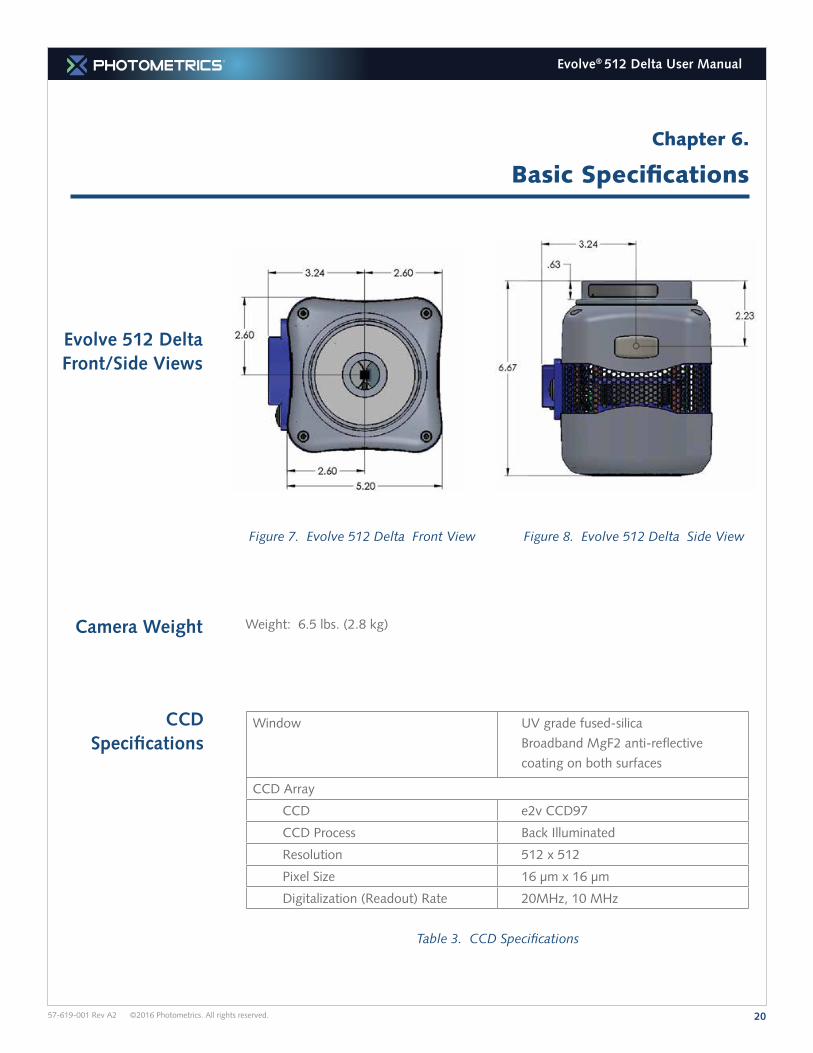
Evolve 512 Delta Front/Side Views
Camera Weight Weight: 6.5 lbs. (2.8 kg)
Figure 7. Evolve 512 Delta Front View Figure 8. Evolve 512 Delta Side View
CCD Specifications
Window UV grade fused-silica
Broadband MgF2 anti-reflective
coating on both surfaces
CCD Array
CCD e2v CCD97
CCD Process Back Illuminated
Resolution 512 x 512
Pixel Size 16 µm x 16 µm
Digitalization (Readout) Rate 20MHz, 10 MHz
Table 3. CCD Specifications
Chapter 6.
Basic Specifications
2157-619-001 Rev A2 ©2016 Photometrics. All rights reserved.
Evolve® 512 Delta User Manual
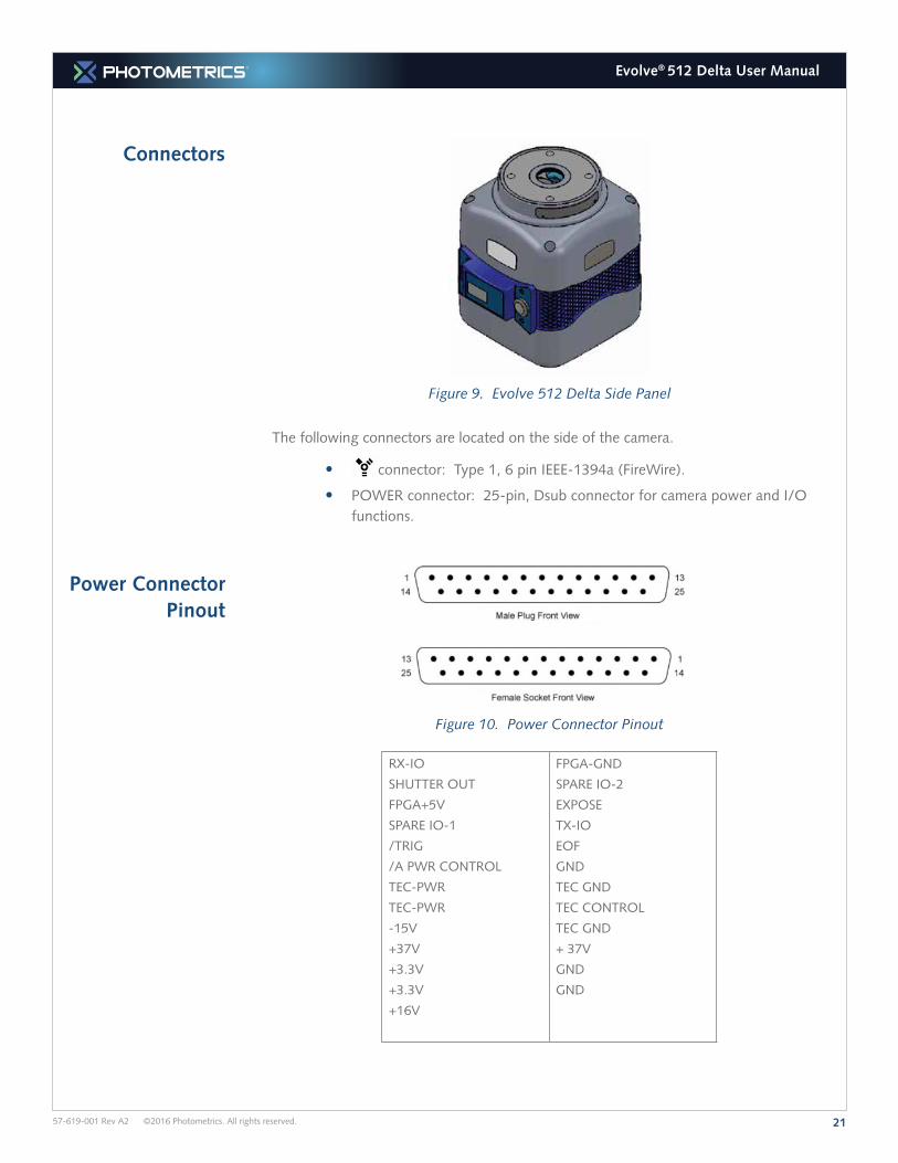
Connectors
Power Connector Pinout
Figure 10. Power Connector Pinout
RX-IO
SHUTTER OUT
FPGA+5V
SPARE IO-1
/TRIG
/A PWR CONTROL
TEC-PWR
TEC-PWR
-15V
+37V
+3.3V
+3.3V
+16V
FPGA-GND
SPARE IO-2
EXPOSE
TX-IO
EOF
GND
TEC GND
TEC CONTROL
TEC GND
+ 37V
GND
GND
Figure 9. Evolve 512 Delta Side Panel
The following connectors are located on the side of the camera.
• connector: Type 1, 6 pin IEEE-1394a (FireWire).
• POWER connector: 25-pin, Dsub connector for camera power and I/O functions.
2257-619-001 Rev A2 ©2016 Photometrics. All rights reserved.
Evolve® 512 Delta User Manual
I/O Connector Pinout
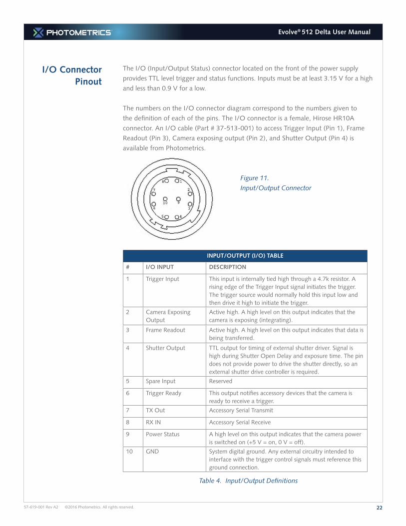
The I/O (Input/Output Status) connector located on the front of the power supply
provides TTL level trigger and status functions. Inputs must be at least 3.15 V for a high
and less than 0.9 V for a low.
The numbers on the I/O connector diagram correspond to the numbers given to
the definition of each of the pins. The I/O connector is a female, Hirose HR10A
connector. An I/O cable (Part # 37-513-001) to access Trigger Input (Pin 1), Frame
Readout (Pin 3), Camera exposing output (Pin 2), and Shutter Output (Pin 4) is
available from Photometrics.
Figure 11.
Input/Output Connector
INPUT/OUTPUT (I/O) TABLE
# I/O INPUT DESCRIPTION
1 Trigger Input This input is internally tied high through a 4.7k resistor. A rising edge of the Trigger Input signal initiates the trigger. The trigger source would normally hold this input low and then drive it high to initiate the trigger.
2 Camera Exposing Output
Active high. A high level on this output indicates that the camera is exposing (integrating).
3 Frame Readout Active high. A high level on this output indicates that data is being transferred.
4 Shutter Output TTL output for timing of external shutter driver. Signal is high during Shutter Open Delay and exposure time. The pin does not provide power to drive the shutter directly, so an external shutter drive controller is required.
5 Spare Input Reserved
6 Trigger Ready This output notifies accessory devices that the camera is ready to receive a trigger.
7 TX Out Accessory Serial Transmit
8 RX IN Accessory Serial Receive
9 Power Status A high level on this output indicates that the camera power is switched on (+5 V = on, 0 V = off).
10 GND System digital ground. Any external circuitry intended to interface with the trigger control signals must reference this ground connection.
Table 4. Input/Output Definitions
2357-619-001 Rev A2 ©2016 Photometrics. All rights reserved.
Evolve® 512 Delta User Manual
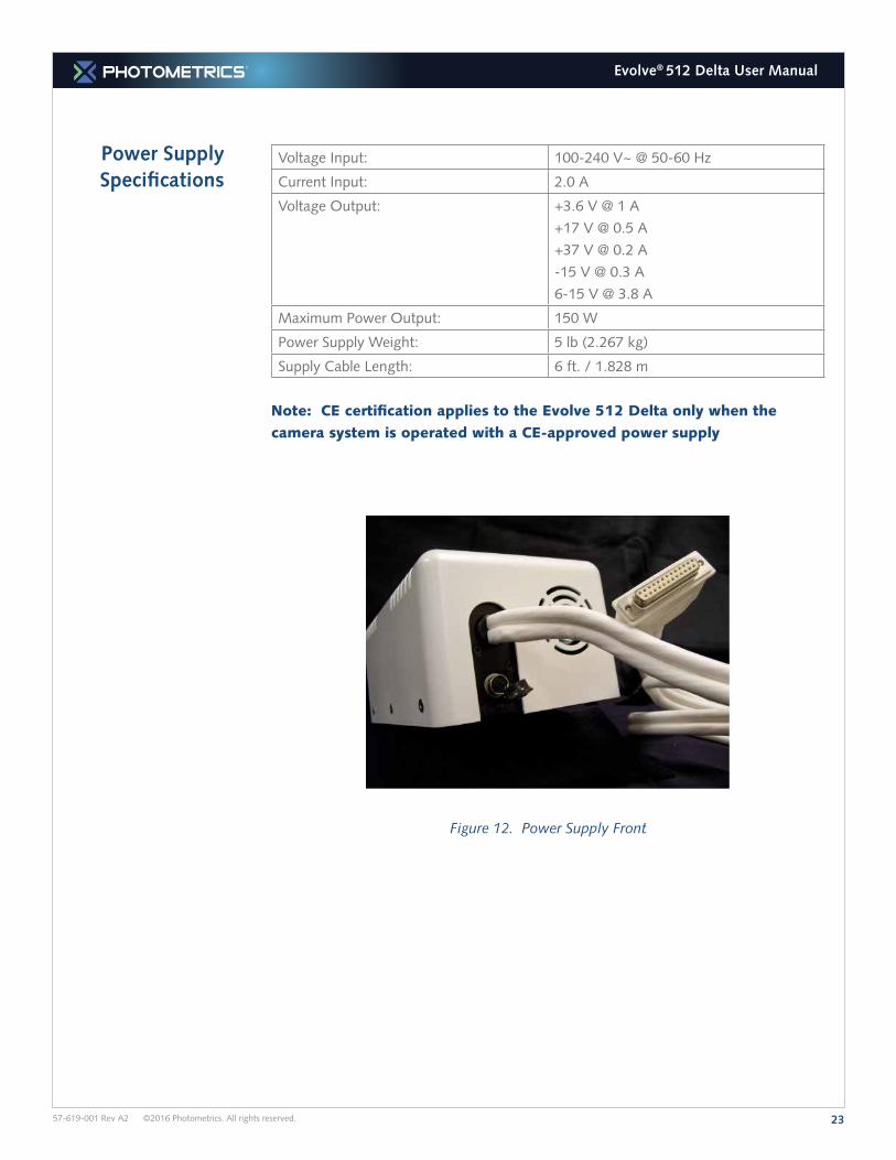
Power Supply Specifications
Voltage Input: 100-240 V~ @ 50-60 Hz
Current Input: 2.0 A
Voltage Output: +3.6 V @ 1 A
+17 V @ 0.5 A
+37 V @ 0.2 A
-15 V @ 0.3 A
6-15 V @ 3.8 A
Maximum Power Output: 150 W
Power Supply Weight: 5 lb (2.267 kg)
Supply Cable Length: 6 ft. / 1.828 m
Note: CE certification applies to the Evolve 512 Delta only when the
camera system is operated with a CE-approved power supply
Figure 12. Power Supply Front
2457-619-001 Rev A2 ©2016 Photometrics. All rights reserved.
Evolve® 512 Delta User Manual
Appendix
Evolve LC with Ambient Cooler
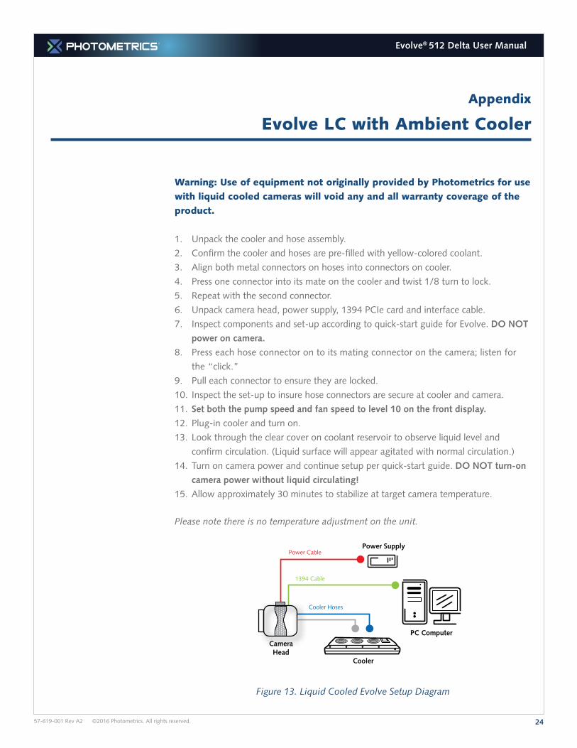
Warning: Use of equipment not originally provided by Photometrics for use
with liquid cooled cameras will void any and all warranty coverage of the
product.
1. Unpack the cooler and hose assembly.
2. Confirm the cooler and hoses are pre-filled with yellow-colored coolant.
3. Align both metal connectors on hoses into connectors on cooler.
4. Press one connector into its mate on the cooler and twist 1/8 turn to lock.
5. Repeat with the second connector.
6. Unpack camera head, power supply, 1394 PCIe card and interface cable.
7. Inspect components and set-up according to quick-start guide for Evolve. DO NOT
power on camera.
8. Press each hose connector on to its mating connector on the camera; listen for
the “click.”
9. Pull each connector to ensure they are locked.
10. Inspect the set-up to insure hose connectors are secure at cooler and camera.
11. Set both the pump speed and fan speed to level 10 on the front display.
12. Plug-in cooler and turn on.
13. Look through the clear cover on coolant reservoir to observe liquid level and
confirm circulation. (Liquid surface will appear agitated with normal circulation.)
14. Turn on camera power and continue setup per quick-start guide. DO NOT turn-on
camera power without liquid circulating!
15. Allow approximately 30 minutes to stabilize at target camera temperature.
Please note there is no temperature adjustment on the unit.
Power Supply
PC Computer
Cooler
Power Cable
1394 Cable
Cooler Hoses
CameraHead
Figure 13. Liquid Cooled Evolve Setup Diagram
2557-619-001 Rev A2 ©2016 Photometrics. All rights reserved.
Evolve® 512 Delta User Manual
INDEX
AApplication Settings, 17
BBinning, 9Bulb Mode, 14
CCCD Specifications, 20Cleaning, 2Connectors, 21
EEMCCD Sensor Structure, 6EM Gain, 6Environmental Requirements, 2Evolve Liquid Cooled, 24
FFireWire, 4
GGain States, 8
HHost Computer, 4
II/O Connector Pinout, 22
LLenses, 2Low Light Detection, 6
MMicroscopes, 2Multiple Cameras, 4
NNon-Overlap Mode, 9
OOffset (Bias), 8Operating Frequencies, 8Overlap Mode, 10
PPower Connector Pinout, 21Power Supply, 23PVCAM Error, 19
RRapid-Cal, 15Repairs, 2
SShutter Signal Behavior, 11SMART Streaming, 15Software Installation, 4Storage Requirements, 2Strobe Mode, 13
TTriggered Operation, 11Trigger First Mode, 11Tripods, 2
WWarranty, iii
2657-619-001 Rev A2 ©2016 Photometrics. All rights reserved.
Evolve® 512 Delta User Manual
www.photometrics.com
Main Phone: +1 520.889.9933
Support: +1 604.530.5800 / +1 800.874.9789