Embed Size (px)
Citation preview

User Manual
REF 1067236
1067235JH 12/3/09

For Technical Support and Customer Service, contact:
USA and Canada: 1-800-345-6443 or 1-724-387-4000 Respironics Europe, Africa, Middle East: +33-1-47-52-30-00 Respironics Asia Pacific: +852-3194-2280 Facsimile: +1-724-387-5012
USA Respironics California, Inc. 2271 Cosmos Court Carlsbad, CA 92011
Email and web addresses: [email protected] [email protected] www.philips.com\healthcare
Authorized European Representative: Respironics Deutschland GmbH Gewerbestrasse 17 D-82211 Herrsching Germany +49 8152 93060
© 2009 Koninklijke Philips Electronics N.V. All rights reserved.
This work is protected under Title 17 of the United States copyright code and is the sole property of Philips Respironics. No part of this document may be copied or otherwise reproduced, or stored in any electronic information retrieval system, except as specifically permitted under United States copyright law, without the prior written consent of Philips Respironics.

Table of Contents
i
Chapter 1. Introduction....................................................................................................................................... 1
Package Contents .................................................................................................................1
Intended Use ..........................................................................................................................2
Warnings and Cautions ......................................................................................................3
Warnings .........................................................................................................................3
Cautions ..........................................................................................................................8
Notes ..............................................................................................................................10
Contraindications ...............................................................................................................11
System Overview ................................................................................................................11
Symbols ..................................................................................................................................12
Front Panel ...................................................................................................................12
Rear and Side Panels .................................................................................................12
Chapter 2. System Description ........................................................................................................................15
Front Panel Features ..........................................................................................................15
Buttons ..........................................................................................................................15
Visual Indicators .........................................................................................................16
Display Screen .............................................................................................................16
Side and Rear Panel Features .........................................................................................17
Chapter 3. Modes, Features, and Alarms......................................................................................................19
Therapy Modes ....................................................................................................................19
Breath Types.................................................................................................................20
Therapy Mode Table .................................................................................................21
Volume Control Ventilation Therapy Modes ....................................................27
Trilogy 202user manual
Table of Contents
Trilogy 202 user manual
ii
Therapy Mode Features ...................................................................................................30
Flex Comfort Feature ................................................................................................30
Ramp ..............................................................................................................................31
Rise Time .......................................................................................................................32
AVAPS Feature .............................................................................................................32
Flow Pattern Types ....................................................................................................34
Sigh Feature .................................................................................................................35
Dual Prescription Feature .......................................................................................36
Triggering ....................................................................................................................36
BTPS Compensation..................................................................................................41
Ventilator Alarms ................................................................................................................41
Loss of Power Alarm ..................................................................................................41
Ventilator Inoperative Alarm .................................................................................41
Ventilator Service Required Alarm .......................................................................41
Check Circuit Alarm ..................................................................................................42
Low Circuit Leak Alarm ...........................................................................................42
High Expiratory Pressure Alarm ...........................................................................42
Low Expiratory Pressure Alarm ............................................................................42
High Internal Oxygen Alarm .................................................................................42
High Oxygen Flow .....................................................................................................43
Low Oxygen Flow ......................................................................................................43
High Oxygen Inlet Pressure ....................................................................................43
Low Oxygen Inlet Pressure .....................................................................................43
Circuit Disconnect Alarm ........................................................................................43
Apnea Alarm ...............................................................................................................44
High Vte Alarm ............................................................................................................44
Low Vte Alarm ............................................................................................................44
High Vti Alarm .............................................................................................................44
Low Vti Alarm .............................................................................................................45
Table of Contents
iii
High Respiratory Rate Alarm .................................................................................45
Low Respiratory Rate Alarm ..................................................................................45
High Inspiratory Pressure Alarm ..........................................................................45
Low Inspiratory Pressure Alarm ...........................................................................46
High Minute Ventilation Alarm ............................................................................46
Low Minute Ventilation Alarm ..............................................................................46
Low Battery Alarm .....................................................................................................46
High Temperature Alarm .......................................................................................47
Replace Detachable Battery Alarm ......................................................................47
Ventilator Service Recommended Alarm ..........................................................47
AC Power Disconnected Alarm .............................................................................48
Keypad Stuck Alarm .................................................................................................48
Battery Discharging Stopped due to Temperature Info Message ............48
Battery Not Charging due to Temperature Info Message ..........................48
Battery Not Charging Info Message ....................................................................48
Check External Battery Info Message .................................................................49
Battery Depleted Info Message ...........................................................................49
External Battery Disconnected Info Message ..................................................49
Detachable Battery Disconnected Info Message ...........................................49
Start On Battery Info Message ..............................................................................49
Card Error Info Message .........................................................................................49
Chapter 4. Ventilator Setup ...............................................................................................................................51
Position the Device ............................................................................................................52
Install the Air Filter .............................................................................................................52
Supply Power to the Device............................................................................................52
Using AC Power ..........................................................................................................52
Using DC Power ..........................................................................................................54
Device Power Source Indicators ...........................................................................58
Battery Disposal..........................................................................................................60
First Time Use ..............................................................................................................60
Trilogy 202 user manual
iv
Connect the Breathing Circuit to the Ventilator ......................................................60
Connect a Water Trap .......................................................................................................64
Connecting Oxygen ...........................................................................................................64
Installing an O2 Inlet Connector ..........................................................................64
Connect the Remote Alarm (Optional) .......................................................................65
Chapter 5. Viewing and Changing Settings ................................................................................................67
Keypad Lock Feature .........................................................................................................67
Accessing the Setting Screens .......................................................................................68
Full Menu Access Mode ...........................................................................................68
Accessing the Startup and Monitor Screens ............................................................70
Monitor Screen Indicators ......................................................................................72
On-Screen Button Panel ..........................................................................................77
Navigating the Menu Screens ........................................................................................77
Changing and Viewing Settings in Full Menu Access Mode ...............................78
Changing the Device Settings and Alarms .......................................................79
Viewing and Changing Options Menu Items ..................................................93
Viewing the Alarm Log ............................................................................................97
Viewing the Event Log .............................................................................................98
Viewing Device Information ..................................................................................99
Updating Prescriptions Using the SD Card ............................................................ 100
Changing and Viewing Settings in Limited Menu Access Mode .................... 104
Activating a Primary or Secondary Prescription .......................................... 105
Viewing and Changing My Settings Menu Items ........................................ 106
Connecting the Ventilator to the Patient ................................................................ 108
Chapter 6. Ventilator Alarms ..........................................................................................................................109
Audible and Visual Alarm Indicators ......................................................................... 110
Alarm LED Indicators ............................................................................................. 110
Audible Indicators .................................................................................................. 111
Alarm Messages ...................................................................................................... 112
Remote Alarm .......................................................................................................... 114
Table of Contents
v
Audio Pause and Alarm Reset Features ................................................................... 115
Audio Pause .............................................................................................................. 115
Alarm Reset ............................................................................................................... 115
Alarm Volume Control ........................................................................................... 116
What to Do When An Alarm Occurs .......................................................................... 116
Alarm Summary Table .................................................................................................... 117
Chapter 7. Cleaning and Maintenance .......................................................................................................123
Cleaning the Ventilator .................................................................................................. 123
Cleaning and Replacing the Air Inlet Filter ............................................................. 124
Cleaning the Patient Circuit ......................................................................................... 125
Reusable Circuit Cleaning Instructions .......................................................... 125
Preventive Maintenance ............................................................................................... 126
Chapter 8. Troubleshooting ............................................................................................................................127Chapter 9. Accessories ......................................................................................................................................131
Adding a Humidifier ....................................................................................................... 131
Adding Supplemental Oxygen to the Device ....................................................... 131
Oxygen Blending Module Warnings ................................................................ 132
Fixed Flow Oxygen Warnings ............................................................................. 132
Using a Remote Alarm Unit.......................................................................................... 133
Using a Nurse Call System ............................................................................................ 134
Using a Secure Digital (SD) Card ................................................................................ 134
Using the Philips Respironics DirectView Software ............................................ 135
Chapter 10. System Checkout Procedures ................................................................................................137
Tools Required .................................................................................................................. 137
Visual Inspection .............................................................................................................. 138
Initial Setup ........................................................................................................................ 138
Settings and Alarms Tests ............................................................................................. 138
Battery Function Verification ....................................................................................... 148
Alarm and Event Log Clean-Up .................................................................................. 149
Results ................................................................................................................................. 150

Trilogy 202 user manual
vi
Chapter 11. Technical Specifications ...........................................................................................................151Chapter 12. Glossary .........................................................................................................................................155Chapter 13. EMC Information ........................................................................................................................161Index ........................................................................................................................................................................165Limited Warranty .................................................................................................................................................169
Chapter 1 Introduction
1
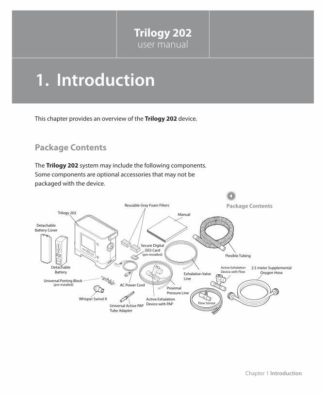
This chapter provides an overview of the Trilogy 202 device.
Package Contents
The Trilogy 202 system may include the following components. Some components are optional accessories that may not be packaged with the device.
Manual
AC Power Cord
Flexible Tubing
Universal Porting Block
Reusable Gray Foam Filters
Secure Digital(SD) Card
(pre-installed)
DetachableBattery
Active ExhalationDevice with PAP
(pre-installed)
Exhalation ValveLine
Trilogy 202
Proximal Pressure Line
Whisper Swivel II
Active ExhalationDevice with Flow
Flow SensorUniversal Active PAP Tube Adapter
2.5 meter Supplemental Oxygen Hose
DetachableBattery Cover
Package Contents
Trilogy 202user manual
1. Introduction
Trilogy 202 user manual
2
Intended Use
The Philips Respironics Trilogy 202 system provides continuous or intermittent ventilatory support for the care of individuals who require mechanical ventilation with or without air/oxygen blending. Trilogy 202 is intended for pediatric through adult patients weighing at least 5 kg (11 lbs.).
The device is intended to be used in hospitals and institutions, and for portable applications such as wheelchairs and gurneys only when in an institutional setting. It may be used for both invasive and non-invasive ventilation. It is not intended to be used as a transport ventilator.
The system is recommended to be used only with various combinations of Philips Respironics-approved patient circuit accessories, such as patient interface devices, humidifiers, water traps, and circuit tubing.
Chapter 1 Introduction
3
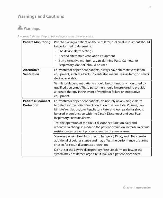
Warnings and Cautions
Warnings
A warning indicates the possibility of injury to the user or operator.
Patient Monitoring Prior to placing a patient on the ventilator, a clinical assessment should be performed to determine:
The device alarm settings •Needed alternative ventilation equipment •If an alternative monitor (i.e., an alarming Pulse Oximeter or •Respiratory Monitor) should be used
Alternative Ventilation
For ventilator dependent patients, always have alternate ventilation equipment, such as a back-up ventilator, manual resuscitator, or similar device, available.
Ventilator dependant patients should be continuously monitored by qualified personnel. These personnel should be prepared to provide alternate therapy in the event of ventilator failure or inoperative equipment.
Patient Disconnect Protection
For ventilator dependent patients, do not rely on any single alarm to detect a circuit disconnect condition. The Low Tidal Volume, Low Minute Ventilation, Low Respiratory Rate, and Apnea alarms should be used in conjunction with the Circuit Disconnect and Low Peak Inspiratory Pressure alarms.
Test the operation of the circuit disconnect function daily and whenever a change is made to the patient circuit. An increase in circuit resistance can prevent proper operation of some alarms.
Speaking valves, Heat Moisture Exchangers (HMEs), and filters create additional circuit resistance and may affect the performance of alarms chosen for circuit disconnect protection.
Do not set the Low Peak Inspiratory Pressure alarm too low, or the system may not detect large circuit leaks or a patient disconnect.
Trilogy 202 user manual
4
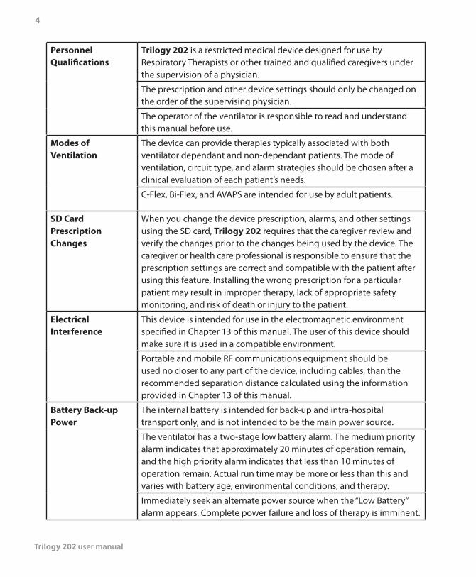
Personnel Qualifications
Trilogy 202 is a restricted medical device designed for use by Respiratory Therapists or other trained and qualified caregivers under the supervision of a physician.
The prescription and other device settings should only be changed on the order of the supervising physician.
The operator of the ventilator is responsible to read and understand this manual before use.
Modes of Ventilation
The device can provide therapies typically associated with both ventilator dependant and non-dependant patients. The mode of ventilation, circuit type, and alarm strategies should be chosen after a clinical evaluation of each patient’s needs.
C-Flex, Bi-Flex, and AVAPS are intended for use by adult patients.
SD Card Prescription Changes
When you change the device prescription, alarms, and other settings using the SD card, Trilogy 202 requires that the caregiver review and verify the changes prior to the changes being used by the device. The caregiver or health care professional is responsible to ensure that the prescription settings are correct and compatible with the patient after using this feature. Installing the wrong prescription for a particular patient may result in improper therapy, lack of appropriate safety monitoring, and risk of death or injury to the patient.
Electrical Interference
This device is intended for use in the electromagnetic environment specified in Chapter 13 of this manual. The user of this device should make sure it is used in a compatible environment.
Portable and mobile RF communications equipment should be used no closer to any part of the device, including cables, than the recommended separation distance calculated using the information provided in Chapter 13 of this manual.
Battery Back-up Power
The internal battery is intended for back-up and intra-hospital transport only, and is not intended to be the main power source.
The ventilator has a two-stage low battery alarm. The medium priority alarm indicates that approximately 20 minutes of operation remain, and the high priority alarm indicates that less than 10 minutes of operation remain. Actual run time may be more or less than this and varies with battery age, environmental conditions, and therapy.
Immediately seek an alternate power source when the “Low Battery” alarm appears. Complete power failure and loss of therapy is imminent.
Chapter 1 Introduction
5
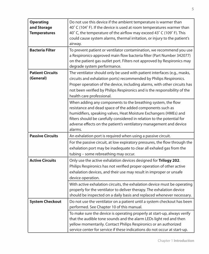
Operating and Storage Temperatures
Do not use this device if the ambient temperature is warmer than 40˚ C (104˚ F). If the device is used at room temperatures warmer than 40˚ C, the temperature of the airflow may exceed 43˚ C (109˚ F). This could cause system alarms, thermal irritation, or injury to the patient’s airway.
Bacteria Filter To prevent patient or ventilator contamination, we recommend you use a Respironics-approved main flow bacteria filter (Part Number 342077) on the patient gas outlet port. Filters not approved by Respironics may degrade system performance.
Patient Circuits (General)
The ventilator should only be used with patient interfaces (e.g., masks, circuits and exhalation ports) recommended by Philips Respironics. Proper operation of the device, including alarms, with other circuits has not been verified by Philips Respironics and is the responsibility of the health care professional.
When adding any components to the breathing system, the flow resistance and dead space of the added components such as humidifiers, speaking valves, Heat Moisture Exchangers (HMEs) and filters should be carefully considered in relation to the potential for adverse effects on the patient’s ventilatory management and device alarms.
Passive Circuits An exhalation port is required when using a passive circuit.
For the passive circuit, at low expiratory pressures, the flow through the exhalation port may be inadequate to clear all exhaled gas from the tubing – some rebreathing may occur.
Active Circuits Only use the active exhalation devices designed for Trilogy 202. Philips Respironics has not verified proper operation of other active exhalation devices, and their use may result in improper or unsafe device operation.
With active exhalation circuits, the exhalation device must be operating properly for the ventilator to deliver therapy. The exhalation device should be inspected on a daily basis and replaced whenever necessary.
System Checkout Do not use the ventilator on a patient until a system checkout has been performed. See Chapter 10 of this manual.
To make sure the device is operating properly at start-up, always verify that the audible tone sounds and the alarm LEDs light red and then yellow momentarily. Contact Philips Respironics or an authorized service center for service if these indications do not occur at start-up.
Trilogy 202 user manual
6
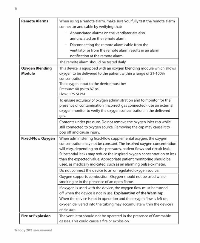
Remote Alarms When using a remote alarm, make sure you fully test the remote alarm connector and cable by verifying that:
Annunciated alarms on the ventilator are also –annunciated on the remote alarm.
Disconnecting the remote alarm cable from the –ventilator or from the remote alarm results in an alarm notification at the remote alarm.
The remote alarm should be tested daily.
Oxygen Blending Module
This device is equipped with an oxygen blending module which allows oxygen to be delivered to the patient within a range of 21-100% concentration. The oxygen input to the device must be: Pressure: 40 psi to 87 psiFlow: 175 SLPM
To ensure accuracy of oxygen administration and to monitor for the presence of contamination (incorrect gas connected), use an external oxygen monitor to verify the oxygen concentration in the delivered gas.
Contents under pressure. Do not remove the oxygen inlet cap while still connected to oxygen source. Removing the cap may cause it to pop off and cause injury.
Fixed-Flow Oxygen When administering fixed-flow supplemental oxygen, the oxygen concentration may not be constant. The inspired oxygen concentration will vary, depending on the pressures, patient flows and circuit leak. Substantial leaks may reduce the inspired oxygen concentration to less than the expected value. Appropriate patient monitoring should be used, as medically indicated, such as an alarming pulse oximeter.
Do not connect the device to an unregulated oxygen source.
Oxygen supports combustion. Oxygen should not be used while smoking or in the presence of an open flame.
If oxygen is used with the device, the oxygen flow must be turned off when the device is not in use. Explanation of the Warning: When the device is not in operation and the oxygen flow is left on, oxygen delivered into the tubing may accumulate within the device’s enclosure.
Fire or Explosion The ventilator should not be operated in the presence of flammable gasses. This could cause a fire or explosion.
Chapter 1 Introduction
7
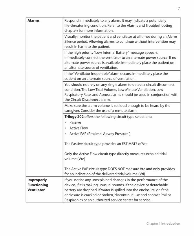
Alarms Respond immediately to any alarm. It may indicate a potentially life-threatening condition. Refer to the Alarms and Troubleshooting chapters for more information.
Visually monitor the patient and ventilator at all times during an Alarm Silence period. Allowing alarms to continue without intervention may result in harm to the patient.
If the high priority “Low Internal Battery” message appears, immediately connect the ventilator to an alternate power source. If no alternate power source is available, immediately place the patient on an alternate source of ventilation.
If the “Ventilator Inoperable” alarm occurs, immediately place the patient on an alternate source of ventilation.
You should not rely on any single alarm to detect a circuit disconnect condition. The Low Tidal Volume, Low Minute Ventilation, Low Respiratory Rate, and Apnea alarms should be used in conjunction with the Circuit Disconnect alarm.
Make sure the alarm volume is set loud enough to be heard by the caregiver. Consider the use of a remote alarm.
Trilogy 202 offers the following circuit type selections:Passive •Active Flow •Active PAP (Proximal Airway Pressure ) •
The Passive circuit type provides an ESTIMATE of Vte.
Only the Active Flow circuit type directly measures exhaled tidal volume (Vte).
The Active PAP circuit type DOES NOT measure Vte and only provides for an indication of the delivered tidal volume (Vti).
Improperly Functioning Ventilator
If you notice any unexplained changes in the performance of the device, if it is making unusual sounds, if the device or detachable battery are dropped, if water is spilled into the enclosure, or if the enclosure is cracked or broken, discontinue use and contact Philips Respironics or an authorized service center for service.
Trilogy 202 user manual
8
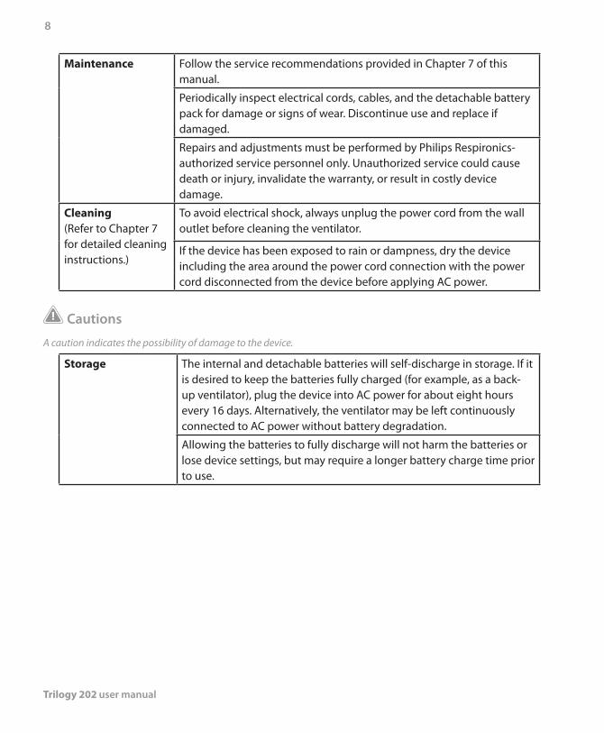
Maintenance Follow the service recommendations provided in Chapter 7 of this manual.
Periodically inspect electrical cords, cables, and the detachable battery pack for damage or signs of wear. Discontinue use and replace if damaged.
Repairs and adjustments must be performed by Philips Respironics-authorized service personnel only. Unauthorized service could cause death or injury, invalidate the warranty, or result in costly device damage.
Cleaning(Refer to Chapter 7 for detailed cleaning instructions.)
To avoid electrical shock, always unplug the power cord from the wall outlet before cleaning the ventilator.
If the device has been exposed to rain or dampness, dry the device including the area around the power cord connection with the power cord disconnected from the device before applying AC power.
Cautions
A caution indicates the possibility of damage to the device.
Storage The internal and detachable batteries will self-discharge in storage. If it is desired to keep the batteries fully charged (for example, as a back-up ventilator), plug the device into AC power for about eight hours every 16 days. Alternatively, the ventilator may be left continuously connected to AC power without battery degradation.
Allowing the batteries to fully discharge will not harm the batteries or lose device settings, but may require a longer battery charge time prior to use.
Chapter 1 Introduction
9
Operating and Storage Temperatures
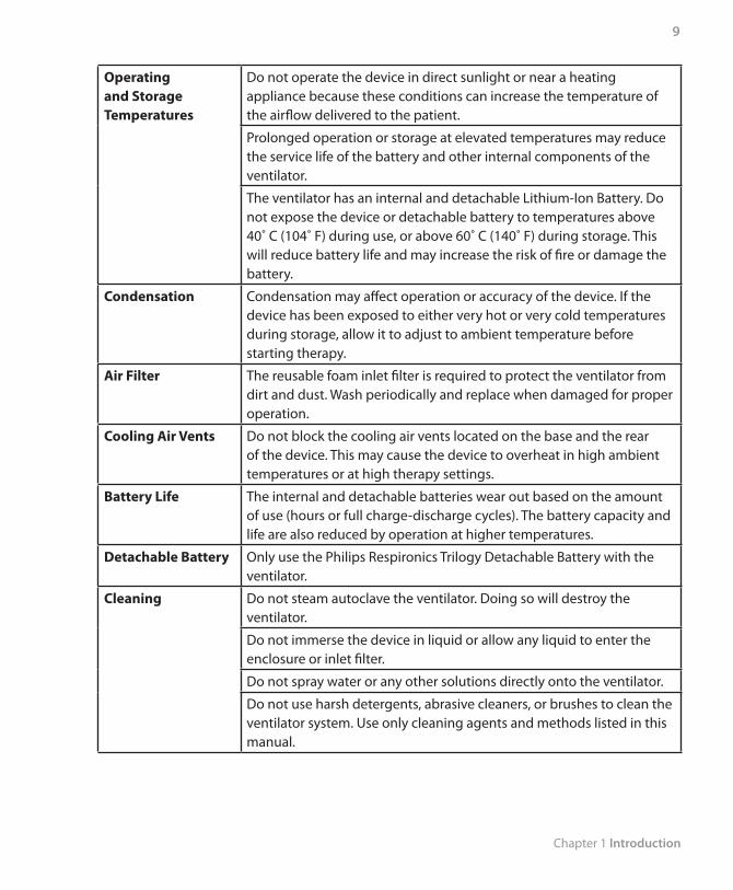
Do not operate the device in direct sunlight or near a heating appliance because these conditions can increase the temperature of the airflow delivered to the patient.
Prolonged operation or storage at elevated temperatures may reduce the service life of the battery and other internal components of the ventilator.
The ventilator has an internal and detachable Lithium-Ion Battery. Do not expose the device or detachable battery to temperatures above 40˚ C (104˚ F) during use, or above 60˚ C (140˚ F) during storage. This will reduce battery life and may increase the risk of fire or damage the battery.
Condensation Condensation may affect operation or accuracy of the device. If the device has been exposed to either very hot or very cold temperatures during storage, allow it to adjust to ambient temperature before starting therapy.
Air Filter The reusable foam inlet filter is required to protect the ventilator from dirt and dust. Wash periodically and replace when damaged for proper operation.
Cooling Air Vents Do not block the cooling air vents located on the base and the rear of the device. This may cause the device to overheat in high ambient temperatures or at high therapy settings.
Battery Life The internal and detachable batteries wear out based on the amount of use (hours or full charge-discharge cycles). The battery capacity and life are also reduced by operation at higher temperatures.
Detachable Battery Only use the Philips Respironics Trilogy Detachable Battery with the ventilator.
Cleaning Do not steam autoclave the ventilator. Doing so will destroy the ventilator.
Do not immerse the device in liquid or allow any liquid to enter the enclosure or inlet filter.
Do not spray water or any other solutions directly onto the ventilator.
Do not use harsh detergents, abrasive cleaners, or brushes to clean the ventilator system. Use only cleaning agents and methods listed in this manual.
Trilogy 202 user manual
10
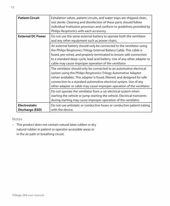
Patient Circuit Exhalation valves, patient circuits, and water traps are shipped clean, not sterile. Cleaning and disinfection of these parts should follow individual institution processes and conform to guidelines provided by Philips Respironics with each accessory.
External DC Power Do not use the same external battery to operate both the ventilator and any other equipment such as power chairs.
An external battery should only be connected to the ventilator using the Philips Respironics Trilogy External Battery Cable. This cable is fused, pre-wired, and properly terminated to ensure safe connection to a standard deep-cycle, lead acid battery. Use of any other adapter or cable may cause improper operation of the ventilator.
The ventilator should only be connected to an automotive electrical system using the Philips Respironics Trilogy Automotive Adapter (when available). This adapter is fused, filtered, and designed for safe connection to a standard automotive electrical system. Use of any other adapter or cable may cause improper operation of the ventilator.
Do not operate the ventilator from a car electrical system when starting the vehicle or jump-starting the vehicle. Electrical transients during starting may cause improper operation of the ventilator.
Electrostatic Discharge (ESD)
Do not use antistatic or conductive hoses or conductive patient tubing with the device.
NotesThis product does not contain natural latex rubber or dry •natural rubber in patient or operator accessible areas or in the air path or breathing circuit.
Chapter 1 Introduction
11
Contraindications
If the patient has any of the following conditions, consult their health care professional before using the device in a non-invasive mode:
Inability to maintain a patent airway or adequately clear •secretions
At risk for aspiration of gastric contents •Diagnosed with acute sinusitis or otitis media •Epistaxis, causing pulmonary aspiration of blood •Hypotension •
System Overview
This ventilator provides both pressure control and volume modes of therapy. The device can provide non-invasive or invasive ventilation. It can be used to provide total therapy to patients as they progress from non-invasive to invasive ventilation.
When prescribed, the device provides numerous special features to help make patient therapy more comfortable. For example, the ramp function allows you to lower the pressure when trying to fall asleep. The air pressure will gradually increase until the prescription pressure is reached. Additionally, the Flex comfort feature provides increased pressure relief during the expiratory phase of breathing.
The ventilator can be operated using several different power sources, including an internal Lithium-Ion battery. This battery is automatically used when the detachable Lithium-Ion battery pack, external Lead Acid battery, or AC power are not available.
This ventilator is equipped with an oxygen blending module which allows oxygen to be delivered to the patient within a range of 21% to 100% concentration.
Trilogy 202 user manual
12
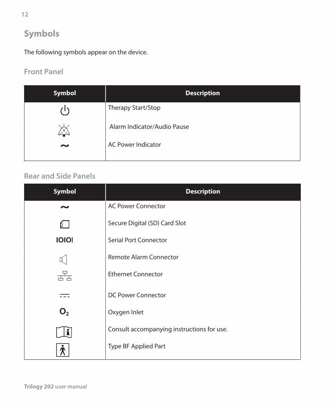
Symbols
The following symbols appear on the device.
Front Panel
Symbol Description
Therapy Start/Stop
Alarm Indicator/Audio Pause
~ AC Power Indicator
Rear and Side Panels
Symbol Description
~ AC Power Connector
Secure Digital (SD) Card Slot
Serial Port Connector
Remote Alarm Connector
Ethernet Connector
DC Power Connector
O2 Oxygen Inlet
Consult accompanying instructions for use.
Type BF Applied Part
Chapter 1 Introduction
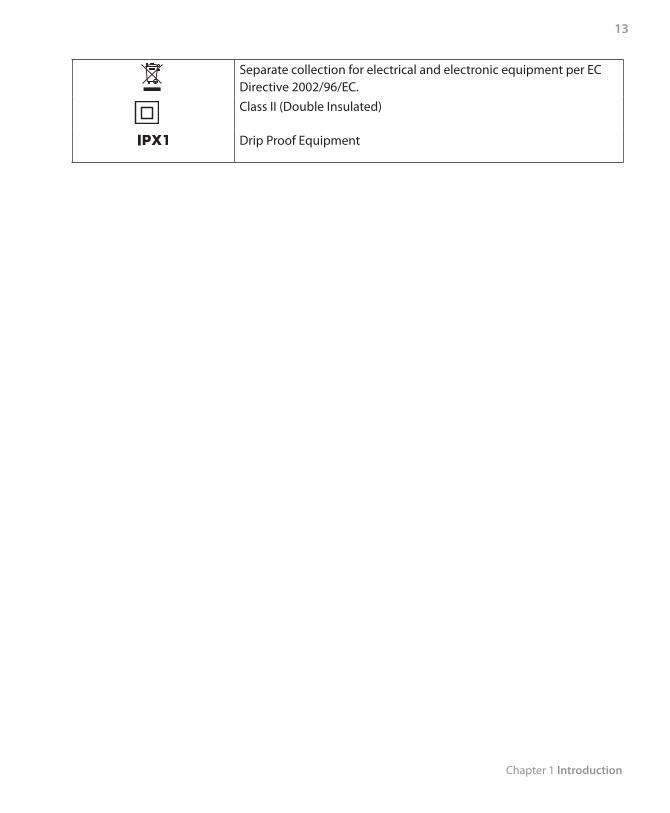
13
Separate collection for electrical and electronic equipment per EC Directive 2002/96/EC.Class II (Double Insulated)
Drip Proof Equipment

Trilogy 202 user manual
14
Chapter 2 System Description
15
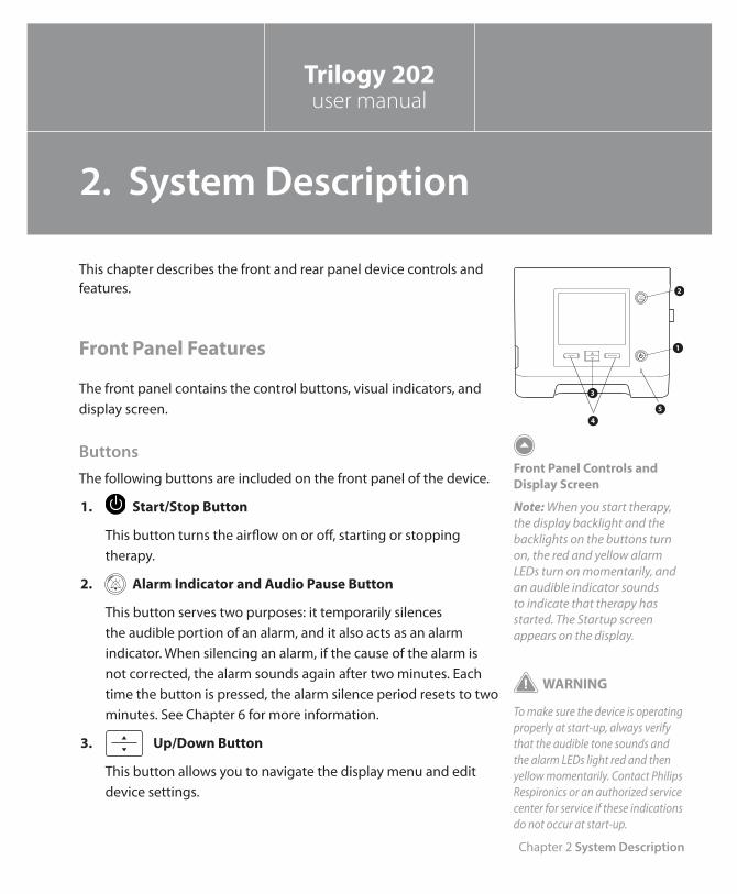
This chapter describes the front and rear panel device controls and features.
Front Panel Features
The front panel contains the control buttons, visual indicators, and display screen.
ButtonsThe following buttons are included on the front panel of the device.
1. Start/Stop Button
This button turns the airflow on or off, starting or stopping therapy.
2. Alarm Indicator and Audio Pause Button
This button serves two purposes: it temporarily silences the audible portion of an alarm, and it also acts as an alarm indicator. When silencing an alarm, if the cause of the alarm is not corrected, the alarm sounds again after two minutes. Each time the button is pressed, the alarm silence period resets to two minutes. See Chapter 6 for more information.
3. Up/Down Button
This button allows you to navigate the display menu and edit device settings.
1
2
4
5
3
Front Panel Controls and Display Screen
Note: When you start therapy, the display backlight and the backlights on the buttons turn on, the red and yellow alarm LEDs turn on momentarily, and an audible indicator sounds to indicate that therapy has started. The Startup screen appears on the display.
WARNING
To make sure the device is operating properly at start-up, always verify that the audible tone sounds and the alarm LEDs light red and then yellow momentarily. Contact Philips Respironics or an authorized service center for service if these indications do not occur at start-up.
Trilogy 202user manual
2. System Description
Trilogy 202 user manual
16
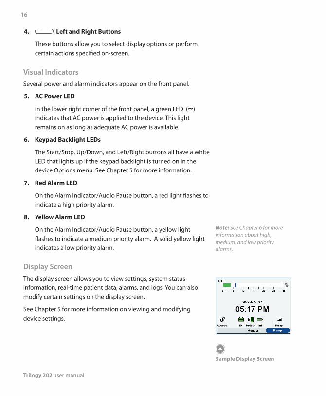
4. Left and Right Buttons
These buttons allow you to select display options or perform certain actions specified on-screen.
Visual IndicatorsSeveral power and alarm indicators appear on the front panel.
5. AC Power LED
In the lower right corner of the front panel, a green LED (~) indicates that AC power is applied to the device. This light remains on as long as adequate AC power is available.
6. Keypad Backlight LEDs
The Start/Stop, Up/Down, and Left/Right buttons all have a white LED that lights up if the keypad backlight is turned on in the device Options menu. See Chapter 5 for more information.
7. Red Alarm LED
On the Alarm Indicator/Audio Pause button, a red light flashes to indicate a high priority alarm.
8. Yellow Alarm LED
On the Alarm Indicator/Audio Pause button, a yellow light flashes to indicate a medium priority alarm. A solid yellow light indicates a low priority alarm.
Display ScreenThe display screen allows you to view settings, system status information, real-time patient data, alarms, and logs. You can also modify certain settings on the display screen.
See Chapter 5 for more information on viewing and modifying device settings.
Note: See Chapter 6 for more information about high, medium, and low priority alarms.
Sample Display Screen
Chapter 2 System Description
17
1
2
3
Right Side Panel
5
4
Left Side Panel
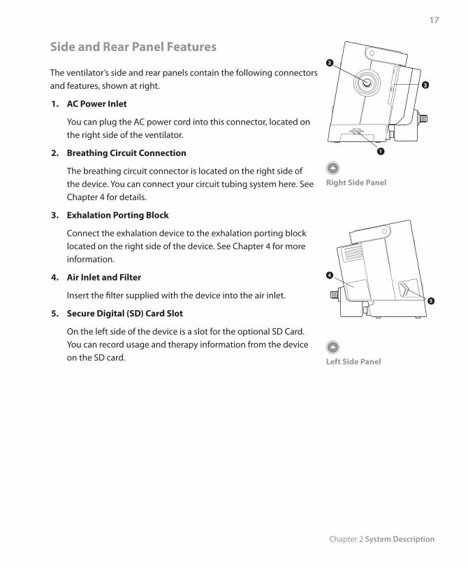
Side and Rear Panel Features
The ventilator’s side and rear panels contain the following connectors and features, shown at right.
1. AC Power Inlet
You can plug the AC power cord into this connector, located on the right side of the ventilator.
2. Breathing Circuit Connection
The breathing circuit connector is located on the right side of the device. You can connect your circuit tubing system here. See Chapter 4 for details.
3. Exhalation Porting Block
Connect the exhalation device to the exhalation porting block located on the right side of the device. See Chapter 4 for more information.
4. Air Inlet and Filter
Insert the filter supplied with the device into the air inlet.
5. Secure Digital (SD) Card Slot
On the left side of the device is a slot for the optional SD Card. You can record usage and therapy information from the device on the SD card.
Trilogy 202 user manual
18
106 8 97
11
12
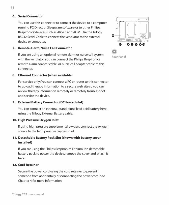
Rear Panel
6. Serial Connector
You can use this connector to connect the device to a computer running PC Direct or Sleepware software or to other Philips Respironics’ devices such as Alice 5 and AOM. Use the Trilogy RS232 Serial Cable to connect the ventilator to the external device or computer.
7. Remote Alarm/Nurse Call Connector
If you are using an optional remote alarm or nurse call system with the ventilator, you can connect the Philips Respironics remote alarm adapter cable or nurse call adapter cable to this connector.
8. Ethernet Connector (when available)
For service only: You can connect a PC or router to this connector to upload therapy information to a secure web site so you can review therapy information remotely or remotely troubleshoot and service the device.
9. External Battery Connector (DC Power Inlet)
You can connect an external, stand-alone lead acid battery here, using the Trilogy External Battery cable.
10. High Pressure Oxygen Inlet
If using high pressure supplemental oxygen, connect the oxygen source to the high pressure oxygen inlet.
11. Detachable Battery Pack Slot (shown with battery cover installed)
If you are using the Philips Respironics Lithium-Ion detachable battery pack to power the device, remove the cover and attach it here.
12. Cord Retainer
Secure the power cord using the cord retainer to prevent someone from accidentally disconnecting the power cord. See Chapter 4 for more information.
Chapter 3 Modes, Features, and Alarms
19
Therapy Modes
The device provides Pressure Control Ventilation (PCV) and Volume Control Ventilation (VCV) for non-invasive and invasive patients.
Pressure Control ventilation delivers a prescribed pressure to the patient according to set breath rate and set inspiration time parameters. This means that each breath is controlled so that a prescribed amount of pressure is delivered to the patient. The device offers six different Pressure Control modes of operation:
CPAP – Continuous Positive Airway Pressure •S – Spontaneous Ventilation •S/T – Spontaneous/Timed Ventilation •T – Timed Ventilation •PC – Pressure Control Ventilation •PC-SIMV – Pressure Controlled Synchronized Intermittent •Mandatory Ventilation
Volume Control ventilation delivers a prescribed inspired tidal volume to the patient according to set breath rate and set inspiratory time parameters. This means that each breath is controlled so that a prescribed tidal volume is delivered to the patient. The device offers three different Volume Control modes of operation:
AC – Assist Control Ventilation •CV – Control Ventilation •SIMV – Synchronized Intermittent Mandatory Ventilation •
Trilogy 202user manual
3. Modes, Features, and Alarms
Trilogy 202 user manual
20
Breath TypesThere are four breath types that apply to the Volume Control and Pressure Control ventilation therapy modes:
Spontaneous •Mandatory •Assisted •Sigh •
Spontaneous Breath
A Spontaneous breath is triggered by the patient. Breaths are initiated by the patient’s inhalation effort, and air delivery is controlled based on the current pressure or volume setting. Breaths are terminated by either the ventilator settings or by the patient’s exhalation effort, depending on the mode selected.
Mandatory Breath
A Mandatory breath (or machine breath) is completely controlled by the ventilator. The ventilator controls both the beginning (triggering) and end (cycling) of the inspiratory phase.
Assisted Breath
An Assisted breath is controlled by both the patient and the ventilator. Breaths are initiated by the patient’s effort and air delivery is controlled by the current pressure or volume settings. Volume Assisted breaths will deliver the prescribed Tidal Volume within the prescribed Inspiratory Time. Pressure Assisted breaths will deliver the prescribed Inspiratory Pressure for the prescribed Inspiratory Time. Breaths are terminated when the Inspiratory Time setting has been reached.
Sigh
A Sigh breath is a breath where 150% of the prescribed volume is delivered. The device will deliver this breath once every 100 Mandatory or Assist breaths when the Sigh setting is enabled. Sigh breaths are only available in volume modes of ventilation.
Chapter 3 Modes, Features, and Alarms
21
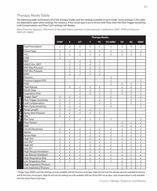
Therapy Mode TableThe following table summarizes all of the therapy modes and the settings available in each mode. Some settings in the table are dependent upon other settings. For instance, if the circuit type is set to Active with Flow, then the Flow Trigger Sensitivity, Leak Compensation, and Flow Cycle settings will display.
Note: Pressure Support, referred to in the table below and later in this manual, is defined as IPAP - EPAP or Pressure - PEEP (PC-SIMV).
Therapy Modes
CPAP S S/T T PC PC-SIMV CV AC SIMV
Dual Prescription √ √ √ √ √ √ √ √ √
Ther
apy
Para
met
ers
Circuit Type √ √ √ √ √ √ √ √ √FiO2 √ √ √ √ √ √ √ √ √CPAP √IPAP √ √ √ √AVAPS (On, Off)* √ √ √ √IPAP Max Pressure √ √ √ √IPAP Min Pressure √ √ √ √EPAP √ √ √ √Pressure √Pressure Support (PS) √ √PEEP √ √ √ √Tidal Volume √ √ √ √ √ √ √Breath Rate √ √ √ √ √ √ √Inspiratory Time √ √ √ √ √ √ √Trigger Type* √ √ √ √ √ √ √Flow Trigger Sensitivity √ √ √ √ √ √ √Leak Compensation √ √ √ √ √ √ √Flow Cycle Sensitivity √ √ √ √ √Ramp Length √ √ √ √ √Ramp Start Pressure √ √ √ √ √Flex * √ √Rise Time √ √ √ √ √ √Flow Pattern √ √ √Sigh √ √ √Circuit Disconnect √ √ √ √ √ √ √ √ √Apnea √ √ √ √ √ √ √ √ √Apnea Rate √ √ √ √ √ √ √ √High Vte* √ √ √ √ √ √ √ √ √Low Vte* √ √ √ √ √ √ √ √ √High Vti* √ √ √ √ √ √ √ √ √Low Vti* √ √ √ √ √ √ √ √ √High Minute Ventilation √ √ √ √ √ √ √ √ √Low Minute Ventilation √ √ √ √ √ √ √ √ √High Respiratory Rate √ √ √ √ √ √ √ √ √Low Respiratory Rate √ √ √ √ √ √ √ √ √High Inspiratory Pressure √ √ √Low Inspiratory Pressure √ √ √
* Trigger Type, AVAPS, and Flex settings are only available with the Passive circuit type. High Vte and Low Vte settings are only available for Passive and Active Flow circuit types. High Vti and Low Vti settings are only available with the Active PAP circuit type. Leak compensation is only available with the Active Flow circuit type.
Trilogy 202 user manual
22
Pressure Control Ventilation Therapy Modes
Pressure Control ventilation modes deliver a prescribed pressure to the patient.
Continuous Positive Airway Pressure (CPAP) Mode
In the Continuous Positive Airway Pressure (CPAP) mode, the device delivers a continuous pressure to the patient at all times. All breaths in this mode are Spontaneous breaths.
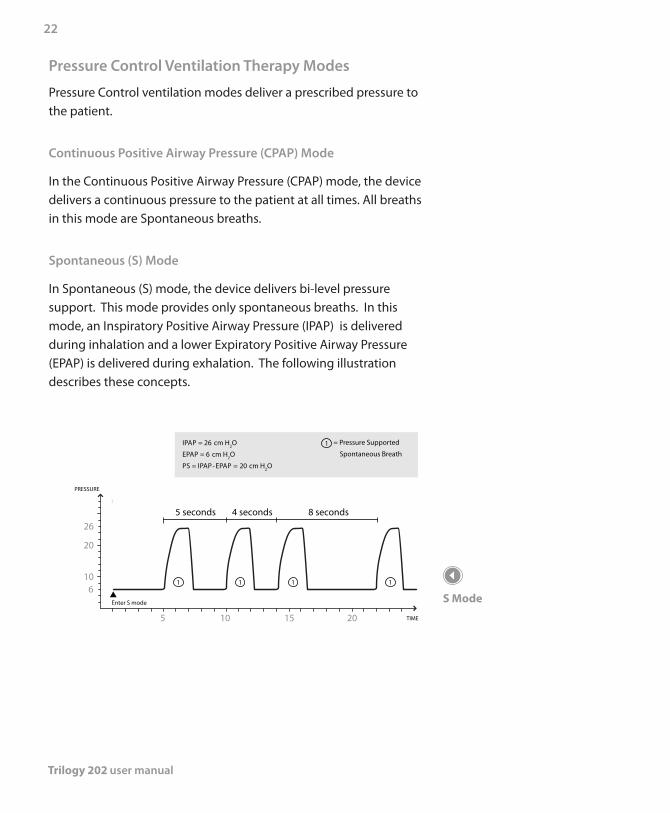
Spontaneous (S) Mode
In Spontaneous (S) mode, the device delivers bi-level pressure support. This mode provides only spontaneous breaths. In this mode, an Inspiratory Positive Airway Pressure (IPAP) is delivered during inhalation and a lower Expiratory Positive Airway Pressure (EPAP) is delivered during exhalation. The following illustration describes these concepts.
IPAP = 26 cm H2O
EPAP = 6 cm H2O
PS = IPAP-EPAP = 20 cm H2O
5 10 15 20
610
20
26
1 1 1
1
1
5 seconds 4 seconds 8 seconds
= Pressure Supported
Spontaneous Breath
Enter S mode
PRESSURE
TIME
S Mode
Chapter 3 Modes, Features, and Alarms
23
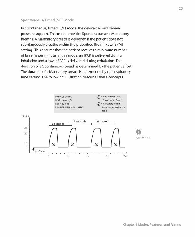
Spontaneous/Timed (S/T) Mode
In Spontaneous/Timed (S/T) mode, the device delivers bi-level pressure support. This mode provides Spontaneous and Mandatory breaths. A Mandatory breath is delivered if the patient does not spontaneously breathe within the prescribed Breath Rate (BPM) setting. This ensures that the patient receives a minimum number of breaths per minute. In this mode, an IPAP is delivered during inhalation and a lower EPAP is delivered during exhalation. The duration of a Spontaneous breath is determined by the patient effort. The duration of a Mandatory breath is determined by the inspiratory time setting. The following illustration describes these concepts.
= Pressure Supported
Spontaneous Breath
= Mandatory Breath
(note longer inspiratory
time)
IPAP = 26 cm H2O
EPAP = 6 cm H2O
Rate = 10 BPM
PS = IPAP-EPAP = 20 cm H2O
1 1
1
12
2
610
20
26
Enter S/T mode
5 10 15 20
PRESSURE
6 seconds
TIME
6 seconds 6 seconds
S/T Mode
Trilogy 202 user manual
24
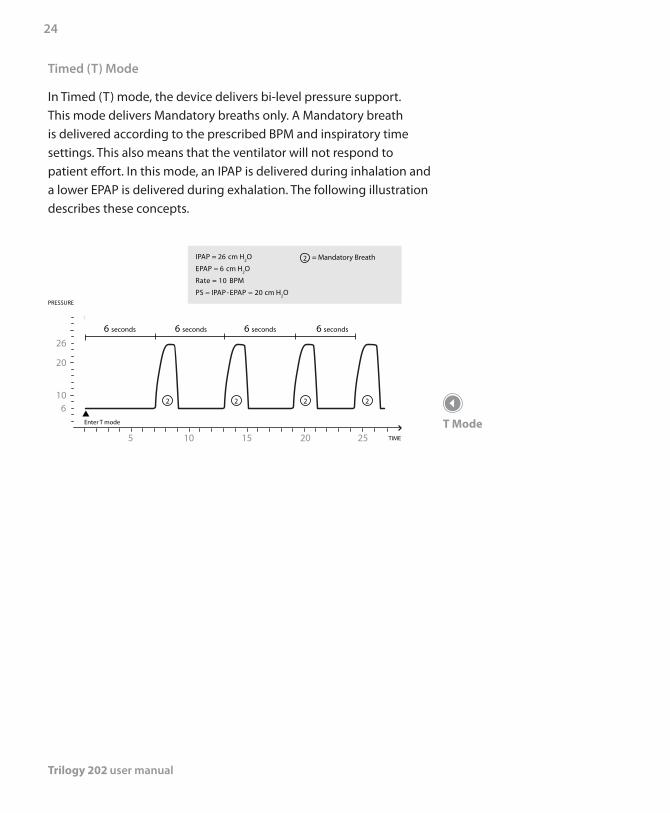
Timed (T) Mode
In Timed (T) mode, the device delivers bi-level pressure support. This mode delivers Mandatory breaths only. A Mandatory breath is delivered according to the prescribed BPM and inspiratory time settings. This also means that the ventilator will not respond to patient effort. In this mode, an IPAP is delivered during inhalation and a lower EPAP is delivered during exhalation. The following illustration describes these concepts.
IPAP = 26 cm H2O
EPAP = 6 cm H2O
Rate = 10 BPM
PS = IPAP-EPAP = 20 cm H2O
6 seconds 6 seconds 6 seconds 6 seconds
2 2 226
10
20
26
= Mandatory Breath2
Enter T mode
5 10 15 20 25
PRESSURE
TIME
T Mode
Chapter 3 Modes, Features, and Alarms
25
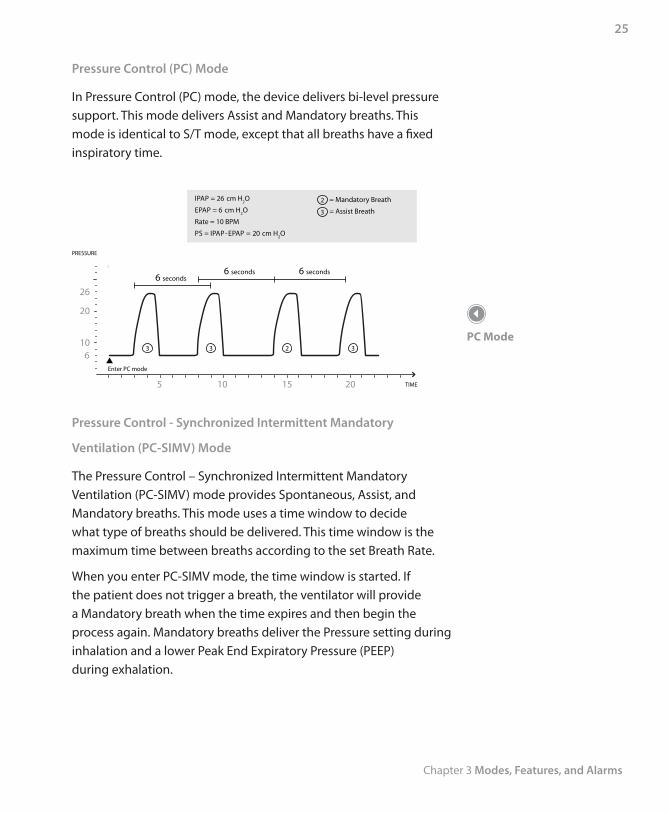
Pressure Control (PC) Mode
In Pressure Control (PC) mode, the device delivers bi-level pressure support. This mode delivers Assist and Mandatory breaths. This mode is identical to S/T mode, except that all breaths have a fixed inspiratory time.
= Mandatory Breath
= Assist Breath
IPAP = 26 cm H2O
EPAP = 6 cm H2O
Rate = 10 BPM
PS = IPAP-EPAP = 20 cm H2O
3 3
3
3 2
2
610
20
26
Enter PC mode
5 10 15 20
PRESSURE
TIME
6 seconds6 seconds 6 seconds
Pressure Control - Synchronized Intermittent Mandatory
Ventilation (PC-SIMV) Mode
The Pressure Control – Synchronized Intermittent Mandatory Ventilation (PC-SIMV) mode provides Spontaneous, Assist, and Mandatory breaths. This mode uses a time window to decide what type of breaths should be delivered. This time window is the maximum time between breaths according to the set Breath Rate.
When you enter PC-SIMV mode, the time window is started. If the patient does not trigger a breath, the ventilator will provide a Mandatory breath when the time expires and then begin the process again. Mandatory breaths deliver the Pressure setting during inhalation and a lower Peak End Expiratory Pressure (PEEP) during exhalation.
PC Mode
Trilogy 202 user manual
26
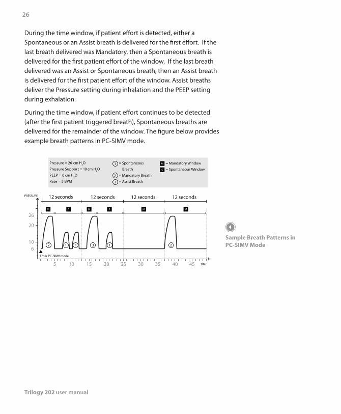
During the time window, if patient effort is detected, either a Spontaneous or an Assist breath is delivered for the first effort. If the last breath delivered was Mandatory, then a Spontaneous breath is delivered for the first patient effort of the window. If the last breath delivered was an Assist or Spontaneous breath, then an Assist breath is delivered for the first patient effort of the window. Assist breaths deliver the Pressure setting during inhalation and the PEEP setting during exhalation.
During the time window, if patient effort continues to be detected (after the first patient triggered breath), Spontaneous breaths are delivered for the remainder of the window. The figure below provides example breath patterns in PC-SIMV mode.
12 seconds
23
3
111
Pressure = 26 cm H2O
Pressure Support = 10 cm H2O
PEEP = 6 cm H2O
Rate = 5 BPM
= Spontaneous
Breath
= Mandatory Breath
= Assist Breath
= Mandatory Window
= Spontaneous Window
1
2
5 10 15 20 25 30 35 40 45
610
20
26
Enter PC-SIMV mode
M
M MM M
S
S S
PRESSURE
TIME
12 seconds 12 seconds 12 seconds
2
Sample Breath Patterns in PC-SIMV Mode
Chapter 3 Modes, Features, and Alarms
27
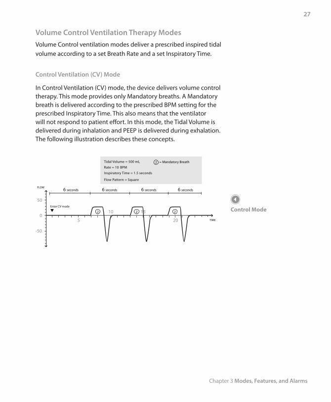
Volume Control Ventilation Therapy ModesVolume Control ventilation modes deliver a prescribed inspired tidal volume according to a set Breath Rate and a set Inspiratory Time.
Control Ventilation (CV) Mode
In Control Ventilation (CV) mode, the device delivers volume control therapy. This mode provides only Mandatory breaths. A Mandatory breath is delivered according to the prescribed BPM setting for the prescribed Inspiratory Time. This also means that the ventilator will not respond to patient effort. In this mode, the Tidal Volume is delivered during inhalation and PEEP is delivered during exhalation. The following illustration describes these concepts.
-50
50
0
Enter CV mode
2 2 2
Tidal Volume = 500 mL
Rate = 10 BPM
Inspiratory Time = 1.5 seconds
Flow Pattern = Square
= Mandatory Breath2
5
15 10
20
FLOW
TIME
6 seconds 6 seconds6 seconds 6 seconds
Control Mode
Trilogy 202 user manual
28
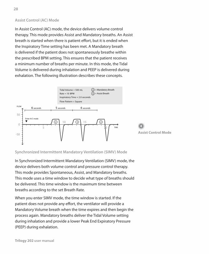
Assist Control (AC) Mode
In Assist Control (AC) mode, the device delivers volume control therapy. This mode provides Assist and Mandatory breaths. An Assist breath is started when there is patient effort, but it is ended when the Inspiratory Time setting has been met. A Mandatory breath is delivered if the patient does not spontaneously breathe within the prescribed BPM setting. This ensures that the patient receives a minimum number of breaths per minute. In this mode, the Tidal Volume is delivered during inhalation and PEEP is delivered during exhalation. The following illustration describes these concepts.
-50
50
0
Enter A/C mode
2 3 2
Tidal Volume = 500 mL
Rate = 10 BPM
Inspiratory Time = 2.0 seconds
Flow Pattern = Square
5
15 10
20
FLOW
TIME
= Mandatory Breath
= Assist Breath3
2
6 seconds6 seconds 5 seconds
Synchronized Intermittent Mandatory Ventilation (SIMV) Mode
In Synchronized Intermittent Mandatory Ventilation (SIMV) mode, the device delivers both volume control and pressure control therapy. This mode provides Spontaneous, Assist, and Mandatory breaths. This mode uses a time window to decide what type of breaths should be delivered. This time window is the maximum time between breaths according to the set Breath Rate.
When you enter SIMV mode, the time window is started. If the patient does not provide any effort, the ventilator will provide a Mandatory Volume breath when the time expires and then begin the process again. Mandatory breaths deliver the Tidal Volume setting during inhalation and provide a lower Peak End Expiratory Pressure (PEEP) during exhalation.
Assist Control Mode
Chapter 3 Modes, Features, and Alarms
29
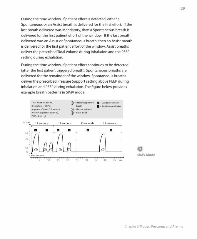
During the time window, if patient effort is detected, either a Spontaneous or an Assist breath is delivered for the first effort. If the last breath delivered was Mandatory, then a Spontaneous breath is delivered for the first patient effort of the window. If the last breath delivered was an Assist or Spontaneous breath, then an Assist breath is delivered for the first patient effort of the window. Assist breaths deliver the prescribed Tidal Volume during inhalation and the PEEP setting during exhalation.
During the time window, if patient effort continues to be detected (after the first patient triggered breath), Spontaneous breaths are delivered for the remainder of the window. Spontaneous breaths deliver the prescribed Pressure Support setting above PEEP during inhalation and PEEP during exhalation. The figure below provides example breath patterns in SIMV mode.
12 seconds12 seconds12 seconds12 seconds
23
3
111
Tidal Volume = 500 mL
Breath Rate = 5 BPM
Inspiratory Time = 3.0 seconds
Pressure Support = 10 cm H2O
PEEP= 6 cm H2O
= Pressure Supported
Breath
= Mandatory Breath
= Assist Breath
= Mandatory Window
= Spontaneous Window
1
2
5 10 15 20 25 30 35 40 45
610
20
26
Enter SIMV mode
M
M MM M
S
S S
PRESSURE
TIME
2
SIMV Mode
Trilogy 202 user manual
30
Therapy Mode Features
The device has several additional features that enhance patient comfort.
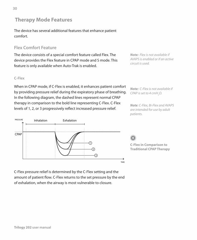
Flex Comfort FeatureThe device consists of a special comfort feature called Flex. The device provides the Flex feature in CPAP mode and S mode. This feature is only available when Auto-Trak is enabled.
C-Flex
When in CPAP mode, if C-Flex is enabled, it enhances patient comfort by providing pressure relief during the expiratory phase of breathing. In the following diagram, the dashed lines represent normal CPAP therapy in comparison to the bold line representing C-Flex. C-Flex levels of 1, 2, or 3 progressively reflect increased pressure relief.
PRESSURE
CPAP
TIME
3
1
2
Inhalation Exhalation
C-Flex pressure relief is determined by the C-Flex setting and the amount of patient flow. C-Flex returns to the set pressure by the end of exhalation, when the airway is most vulnerable to closure.
Note: Flex is not available if AVAPS is enabled or if an active circuit is used.
Note: C-Flex is not available if CPAP is set to 4 cmH2O.
Note: C-Flex, Bi-Flex and AVAPS are intended for use by adult patients.
C-Flex in Comparison to Traditional CPAP Therapy
Chapter 3 Modes, Features, and Alarms
31
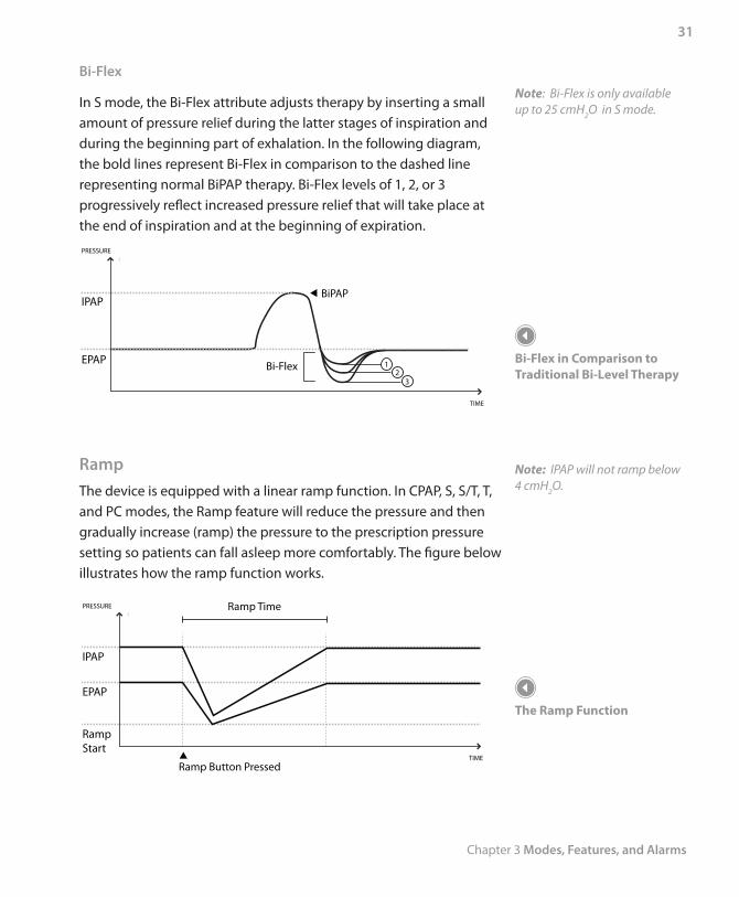
Bi-Flex
In S mode, the Bi-Flex attribute adjusts therapy by inserting a small amount of pressure relief during the latter stages of inspiration and during the beginning part of exhalation. In the following diagram, the bold lines represent Bi-Flex in comparison to the dashed line representing normal BiPAP therapy. Bi-Flex levels of 1, 2, or 3 progressively reflect increased pressure relief that will take place at the end of inspiration and at the beginning of expiration.
PRESSURE
IPAP
EPAP
TIME
BiPAP
Bi-Flex3
12
RampThe device is equipped with a linear ramp function. In CPAP, S, S/T, T, and PC modes, the Ramp feature will reduce the pressure and then gradually increase (ramp) the pressure to the prescription pressure setting so patients can fall asleep more comfortably. The figure below illustrates how the ramp function works.
TIME
Note: Bi-Flex is only available up to 25 cmH2O in S mode.
Bi-Flex in Comparison to Traditional Bi-Level Therapy
Note: IPAP will not ramp below 4 cmH2O.
The Ramp Function
Trilogy 202 user manual
32
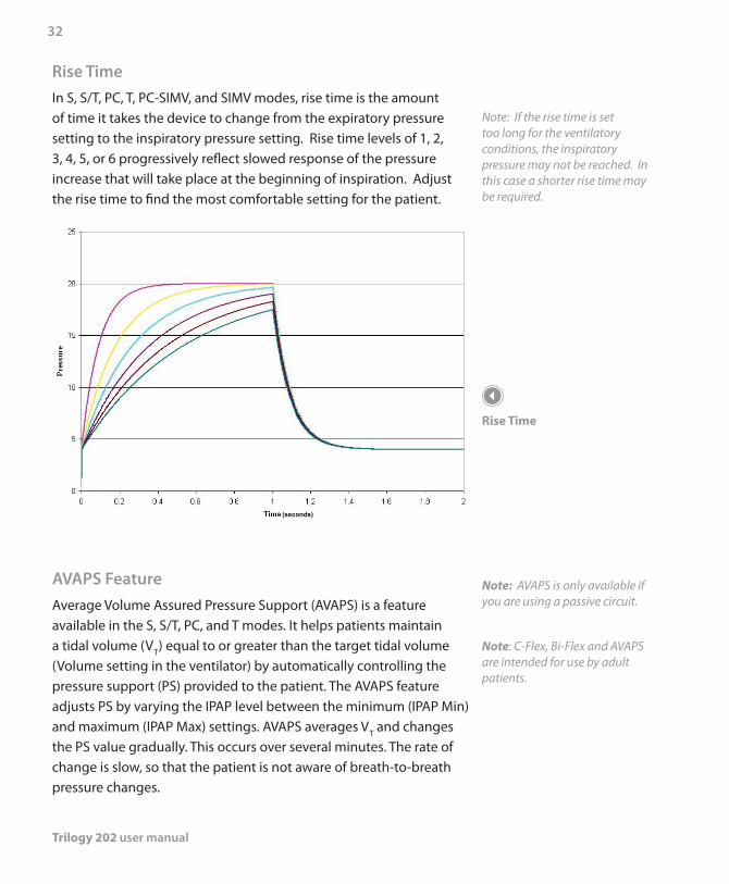
Rise TimeIn S, S/T, PC, T, PC-SIMV, and SIMV modes, rise time is the amount of time it takes the device to change from the expiratory pressure setting to the inspiratory pressure setting. Rise time levels of 1, 2, 3, 4, 5, or 6 progressively reflect slowed response of the pressure increase that will take place at the beginning of inspiration. Adjust the rise time to find the most comfortable setting for the patient.
(seconds)
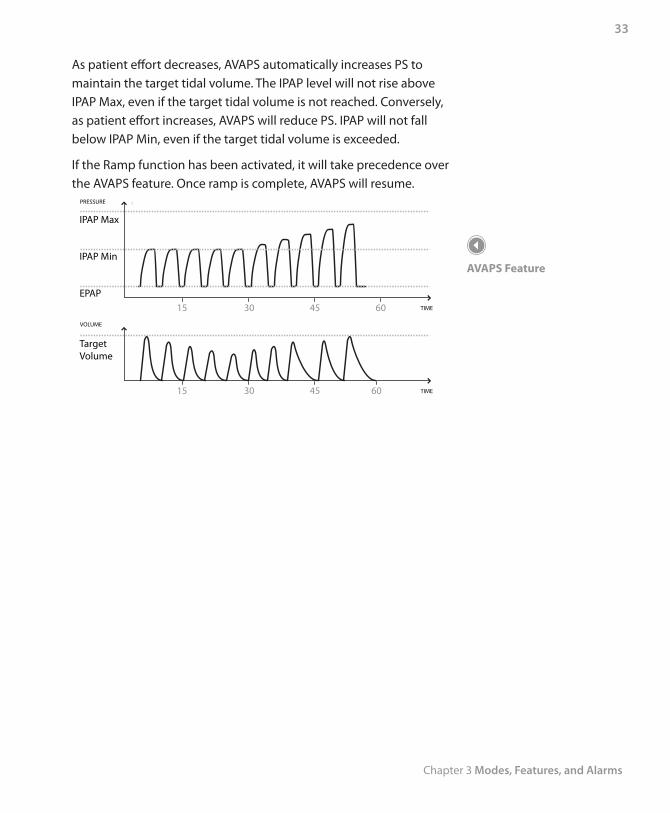
AVAPS FeatureAverage Volume Assured Pressure Support (AVAPS) is a feature available in the S, S/T, PC, and T modes. It helps patients maintain a tidal volume (VT) equal to or greater than the target tidal volume (Volume setting in the ventilator) by automatically controlling the pressure support (PS) provided to the patient. The AVAPS feature adjusts PS by varying the IPAP level between the minimum (IPAP Min) and maximum (IPAP Max) settings. AVAPS averages VT and changes the PS value gradually. This occurs over several minutes. The rate of change is slow, so that the patient is not aware of breath-to-breath pressure changes.
Note: If the rise time is set too long for the ventilatory conditions, the inspiratory pressure may not be reached. In this case a shorter rise time may be required.
Rise Time
Note: AVAPS is only available if you are using a passive circuit.
Note: C-Flex, Bi-Flex and AVAPS are intended for use by adult patients.
Chapter 3 Modes, Features, and Alarms
33
As patient effort decreases, AVAPS automatically increases PS to maintain the target tidal volume. The IPAP level will not rise above IPAP Max, even if the target tidal volume is not reached. Conversely, as patient effort increases, AVAPS will reduce PS. IPAP will not fall below IPAP Min, even if the target tidal volume is exceeded.
If the Ramp function has been activated, it will take precedence over the AVAPS feature. Once ramp is complete, AVAPS will resume.
IPAP Max
IPAP Min
EPAPTIME15 30 45 60
TIME15 30 45 60
PRESSURE
TargetVolume
VOLUME
AVAPS Feature
Trilogy 202 user manual
34
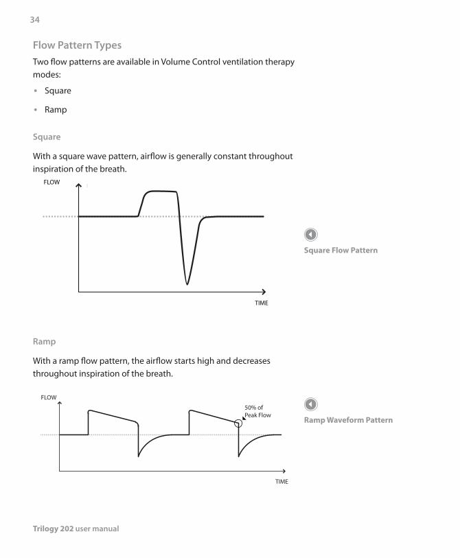
Flow Pattern TypesTwo flow patterns are available in Volume Control ventilation therapy modes:
Square •
Ramp •
Square
With a square wave pattern, airflow is generally constant throughout inspiration of the breath.
FLOW
TIME
Ramp
With a ramp flow pattern, the airflow starts high and decreases throughout inspiration of the breath.
50% of Peak Flow
FLOW
TIME
Square Flow Pattern
Ramp Waveform Pattern
Chapter 3 Modes, Features, and Alarms
35
For the active circuit in volume modes, peak flow is required to be a minimum of 20 l/min. The wave form may be flattened when the combination of Inspiratory Time and Tidal Volume set points would result in a flow of less than 20 l/min. Therefore, for some settings, a Ramp flow pattern may provide a pattern that more closely resembles a Square flow pattern.
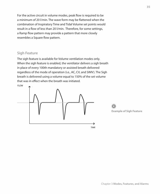
Sigh FeatureThe sigh feature is available for Volume ventilation modes only.When the sigh feature is enabled, the ventilator delivers a sigh breath in place of every 100th mandatory or assisted breath delivered regardless of the mode of operation (i.e., AC, CV, and SIMV). The Sigh breath is delivered using a volume equal to 150% of the set volume that was in effect when the breath was initiated. FLOW
TIME
Example of Sigh Feature
Trilogy 202 user manual
36
Dual Prescription FeatureThe device provides a dual prescription feature that allows you to enter a primary prescription and a secondary prescription for the patient if needed. For example, you can set a primary daytime prescription and secondary nighttime prescription. See Chapter 5 for more information on the dual prescription feature.
Triggering The device can be set to trigger breaths using the Auto-Trak or Flow Trigger sensitivity features.
Digital Auto-Trak Sensitivity
An important characteristic of the device is its ability to recognize and compensate for unintentional leaks in the system and to automatically adjust its trigger and cycle algorithms to maintain optimum performance in the presence of leaks. This feature is known as Digital Auto-Trak Sensitivity. The following sections examine this function in detail by describing the leak tolerance function and sensitivity.
Leak Tolerance
A microprocessor monitors the total flow of the patient circuit and calculates patient flow values.
A. Leak Estimation: Average and Parabolic
The device uses two leak estimation algorithms. A conservation of mass algorithm is used to compute the average leak for a given pressure support relationship. This average leak is used when large leak variations are present in the system. Average leak is a high estimate during EPAP pressure and a low estimate during IPAP pressure. A better leak estimate, enabled by the digital system, is the parabolic leak algorithm. Parabolic leak is proportional to the square of the patient pressure; therefore, the leak estimate is correlated to the changing patient pressure. Both algorithms include unintentional circuit leak and are averaged over several breaths.
Note: Both prescriptions must use the same circuit type.
Note: Auto-Trak is only available if you are using a passive circuit.
Chapter 3 Modes, Features, and Alarms
37
B. Patient Flow
The total circuit flow is comprised of the circuit leak and the patient flow. The calculated patient flow is the total flow minus the circuit leak. Patient flow is a primary input into the triggering and cycling mechanisms.
Auto-Trak Sensitivity
An essential feature of the device while operating in all modes is its ability to effectively sense spontaneous breathing efforts, which causes the ventilator to trigger to inspiration and cycle to expiration. Because no preset sensitivity threshold can assure patient and machine synchrony with changing breathing efforts and circuit leaks, the device continuously tracks patient breathing patterns and automatically adjusts sensitivity thresholds to ensure optimum sensitivity as breathing patterns change or as circuit leaks change. The algorithms used to ensure optimum sensitivity are the Volume Trigger, Shape Signal, Spontaneous Expiratory Threshold (SET), Flow Reversal, Maximum IPAP Time, and Volume Control Cycle.
Volume Trigger (Expiration to Inspiration):
The volume trigger is one method used to trigger inspiration during spontaneous breathing in all modes except T and CV. The volume trigger threshold is 6 ml of accumulated patient inspiratory volume. When patient effort generates inspiratory flow causing 6 ml of volume, inspiration is triggered.
Trilogy 202 user manual
38
Shape Trigger/Shape Cycle (Expiration to Inspiration) (Inspiration to Expiration):
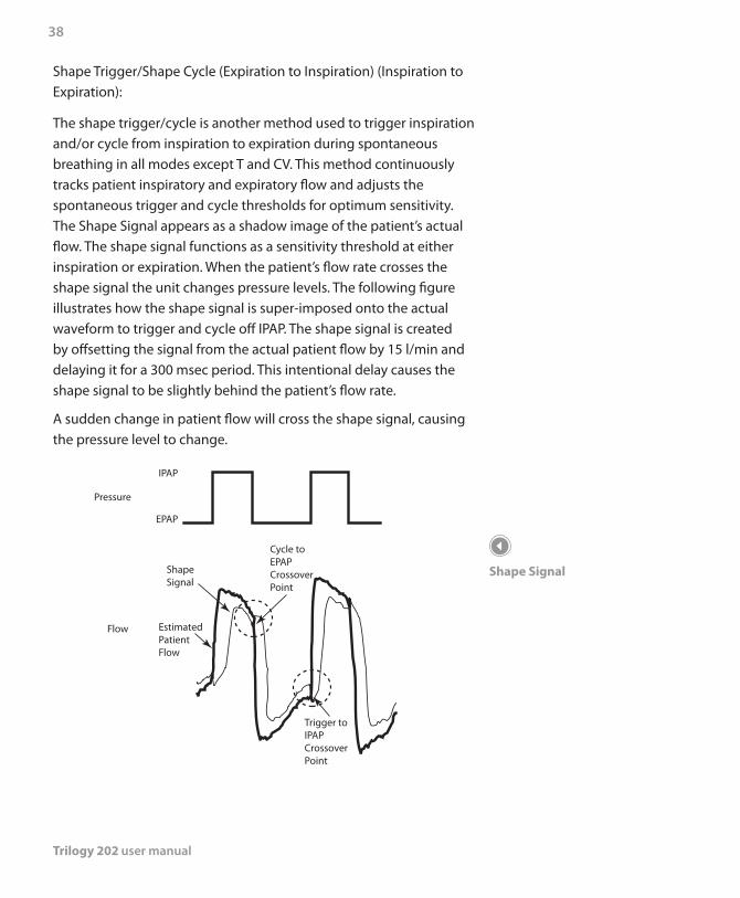
The shape trigger/cycle is another method used to trigger inspiration and/or cycle from inspiration to expiration during spontaneous breathing in all modes except T and CV. This method continuously tracks patient inspiratory and expiratory flow and adjusts the spontaneous trigger and cycle thresholds for optimum sensitivity. The Shape Signal appears as a shadow image of the patient’s actual flow. The shape signal functions as a sensitivity threshold at either inspiration or expiration. When the patient’s flow rate crosses the shape signal the unit changes pressure levels. The following figure illustrates how the shape signal is super-imposed onto the actual waveform to trigger and cycle off IPAP. The shape signal is created by offsetting the signal from the actual patient flow by 15 l/min and delaying it for a 300 msec period. This intentional delay causes the shape signal to be slightly behind the patient’s flow rate.
A sudden change in patient flow will cross the shape signal, causing the pressure level to change.
Pressure
Flow
IPAP
EPAP
ShapeSignal
EstimatedPatientFlow
Trigger toIPAPCrossoverPoint
Cycle toEPAPCrossoverPoint
Shape Signal
Chapter 3 Modes, Features, and Alarms
39
Tracking the patient’s flow pattern with the Shape Signal provides a sensitive mechanism to trigger to inspiration or cycle to expiration in response to changing breathing patterns and circuit leaks.
Spontaneous Expiratory Threshold (Inspiration to Expiration):
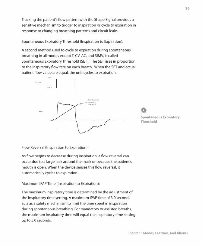
A second method used to cycle to expiration during spontaneous breathing in all modes except T, CV, AC, and SIMV, is called Spontaneous Expiratory Threshold (SET). The SET rises in proportion to the inspiratory flow rate on each breath. When the SET and actual patient flow value are equal, the unit cycles to expiration.
Pressure
Flow
IPAP
EPAP
SpontaneousExpiratoryThreshold
Flow Reversal (Inspiration to Expiration):
As flow begins to decrease during inspiration, a flow reversal can occur due to a large leak around the mask or because the patient’s mouth is open. When the device senses this flow reversal, it automatically cycles to expiration.
Maximum IPAP Time (Inspiration to Expiration):
The maximum inspiratory time is determined by the adjustment of the Inspiratory time setting. A maximum IPAP time of 3.0 seconds acts as a safety mechanism to limit the time spent in inspiration during spontaneous breathing. For mandatory or assisted breaths, the maximum inspiratory time will equal the Inspiratory time setting up to 5.0 seconds.
Spontaneous Expiratory Threshold
Trilogy 202 user manual
40
Volume Control Cycle (Inspiration to Expiration) (Only available during Volume Control Therapy)
An Inspiratory Time setpoint limits the time spent in inspiration during breathing in all modes. Once the time limit is reached, the unit automatically cycles to expiration.
Flow Trigger
Flow trigger provides a manual setting that allows for breath initiation and termination based on a set flow trigger sensitivity and flow cycle sensitivity.
Flow Trigger Sensitivity (Expiration to Inspiration):
The flow trigger initiates when the patient’s inspiratory effort creates a flow equal to or greater than the flow trigger sensitivity setting. The method of the flow trigger is dependent upon the circuit type that is chosen.
Leak Compensation:
When using the Passive Circuit configuration, compensation for both the intentional and unintentional leak is included in the triggering method.
When using the Active PAP Circuit configuration, leak compensation is not available.
When using the Active Flow Circuit configuration, flow trigger with leak compensation may be enabled. The default setting when using the Active Flow Circuit is Leak Compensation On. The clinician has the option to turn off leak compensation; however, unintentional leak will not be compensated. Both options measure the flow at the proximal flow sensor.
Flow Cycle Sensitivity (Inspiration to Expiration):
This cycling method is only active if the Flow Trigger has been selected for the Trigger Type. As flow begins to decrease during inspiration, if the patient flow is less than the flow cycle sensitivity setting, the device will cycle to expiration.
For example: if the flow cycle sensitivity setting is set to 25%, when the flow has decreased by 25% of the peak flow, the device will cycle to the EPAP/PEEP level.
Note: Enabling Leak Compensation when using the Active Flow Circuit configuration only affects triggering and does not affect tidal volume delivery or Vte measurement.
Chapter 3 Modes, Features, and Alarms
41
BTPS CompensationAll flows and volumes used in Trilogy are expressed in BTPS - Body Temperature atmospheric Pressure Saturated with H2O.
All pressures are expressed relative to atmospheric pressure.
Ventilator Alarms
This section describes all of the ventilator alarms and informational messages in order of priority, from high priority alarms to low priority alarms and finally informational messages. Refer to Chapter 6 for more information on alarms.
Loss of Power AlarmThis is a high priority alarm. It may occur when a complete power failure has occurred and power was lost while the device was providing therapy. This may happen if the internal battery was the only power source in use and was completely depleted.
Ventilator Inoperative AlarmThis is a high priority alarm. It occurs when the ventilator detects an internal error or a condition that may affect therapy. The device will shut down if the cause of the failure indicates that the device cannot deliver therapy safely. If the device can deliver therapy at a limited level, the device will continue to deliver limited therapy.
Ventilator Service Required AlarmThis is a high priority alarm. It occurs when the device cannot perform to specification, a backup safety feature is compromised, or the delivery of therapy is compromised. The device continues to operate (possibly in a reduced capacity mode). If the problem is not corrected, the device will generate a reminder message once per hour until the issue is corrected. Additionally, if therapy is stopped, a reminder message will immediately appear when therapy is turned on again.
Trilogy 202 user manual
42
Check Circuit Alarm This is a high priority alarm. It occurs when the device detects a problem with the patient circuit, such as pinched or detached tubing, water condensation in the proximal pressure lines, or problems with the active exhalation device.
Low Circuit Leak Alarm This is a high priority alarm that only occurs with the passive circuit. It occurs when the system detects a problem with the leak device in the passive circuit.
High Expiratory Pressure Alarm This is a high priority alarm. It occurs when the delivered pressure exceeds the target patient pressure during the expiratory phase by 5 cmH2O. This may be due to pinched tubing or the patient having a fast breath rate. The device continues to operate. The alarm will automatically terminate when the delivered pressure comes within 5 cmH2O of the target patient pressure during the expiratory phase.
Low Expiratory Pressure Alarm This is a high priority alarm. It occurs when the delivered pressure is 5 cmH2O or more below the target patient pressure during the expiratory phase. The device continues to operate. The alarm will automatically terminate when the delivered pressure comes within 5 cmH2O of the target patient pressure during the expiratory phase.
High Internal Oxygen Alarm This is a high priority alarm. It occurs when there is a leak in the internal air delivery system that allows oxygen to build up inside the device. The alarm is generated when the internal oxygen concentration reaches 5% above ambient levels.
Chapter 3 Modes, Features, and Alarms
43
High Oxygen FlowThis is a high priority alarm. It occurs when the concentration of oxygen from the device is 10% above the FiO2 set point for more than 30 seconds. This could be caused by a problem with the output of the oxygen source.
Low Oxygen FlowThis is a high priority alarm. It occurs when the concentration of oxygen from the device is 10% below the FiO2 set point for more than 30 seconds. This could be caused by the oxygen source being disconnected from the device, an occlusion in the tubing from the oxygen source to the device, or a problem with the output of the oxygen source.
High Oxygen Inlet PressureThis is a high priority alarm. It occurs when the pressure of the oxygen from the source measures greater than 87 psi.
Low Oxygen Inlet PressureThis is a high priority alarm. It occurs when the pressure of the oxygen from the oxygen source measures less than 40 psi. This could be caused by the oxygen source being disconnected from the device, an occlusion in the tubing from the oxygen source to the device, or a problem with the output of the oxygen source.
Circuit Disconnect AlarmThis is a high priority alarm. It occurs when the breathing circuit is disconnected or has a large leak. The device continues to operate. The alarm will automatically terminate when the leak is fixed for 6 seconds and breaths are delivered again.
WARNINGYou should not rely on any single alarm to detect a circuit disconnect condition. The Low Tidal Volume, Low Minute Ventilation, Low Respiratory Rate, and Apnea alarms should be used in conjunction with the Circuit Disconnect alarm. The Apnea alarm is only intended for spontaneously breathing patients.
Trilogy 202 user manual
44
Apnea Alarm This is a high priority alarm. It occurs when the patient has not triggered a breath within the time specified in the apnea alarm setting. The device continues to operate. The alarm will automatically terminate when two consecutive patient breaths are detected that meet the apnea alarm time setting.
High Vte Alarm
This is a high priority alarm. It occurs when the estimated exhaled tidal volume is greater than the High Vte alarm setting for three consecutive breaths. The device continues to operate. The alarm will automatically terminate when a breath occurs in which the exhaled tidal volume does not reach the High Vte alarm setting.
Low Vte Alarm This is a high priority alarm. It occurs when the estimated exhaled tidal volume is lower than the Low Vte alarm setting for three consecutive breaths. The device continues to operate. The alarm will automatically terminate when a breath occurs in which the exhaled tidal volume exceeds the Low Vte alarm setting.
When AVAPS is on, this alarm will occur when the calculated tidal volume is less than 90% of the target tidal volume setting. The alarm will automatically terminate when a breath occurs in which the exhaled tidal volume is equal or greater to 90% of the target tidal volume setting.
High Vti Alarm
This is a high priority alarm. It occurs when the delivered tidal volume is greater than the High Vti alarm setting for three consecutive breaths. The device continues to operate. The alarm will automatically terminate when a breath occurs in which the delivered tidal volume does not reach the High Vti alarm setting.
Chapter 3 Modes, Features, and Alarms
45
Low Vti Alarm This is a high priority alarm. It occurs when the delivered tidal volume is less than the Low Vti alarm setting for three consecutive breaths. The device continues to operate. The alarm will automatically terminate when a breath occurs in which the delivered tidal volume exceeds the Low Vti alarm setting.
High Respiratory Rate AlarmThis is a high priority alarm. It occurs when the respiratory rate is greater than the High Respiratory Rate alarm setting. The device continues to operate. The alarm will automatically terminate when the measured respiratory rate is less than the High Respiratory Rate alarm setting.
Low Respiratory Rate Alarm This is a high priority alarm. It occurs when the respiratory rate is less than the Low Respiratory Rate alarm setting. The device continues to operate. The alarm will automatically terminate when the measured respiratory rate is greater than the Low Respiratory Rate alarm setting.
High Inspiratory Pressure Alarm This alarm occurs in several stages and escalates from an audible beep for the first two occurrences to a high priority alarm if the problem continues. It is detected differently for volume and pressure therapy modes.
For volume modes, the alarm will sound if the measured patient pressure exceeds the High Inspiratory Pressure setting specified by the clinician. The alarm will automatically terminate when the peak inspiratory pressure is less than or equal to the High Inspiratory Pressure alarm setting.
For pressure modes, the alarm occurs when the delivered pressure exceeds the target patient pressure by 5 cmH2O or more during the inspiratory phase. The device will automatically cycle to the expiratory phase and continue to operate. The alarm will automatically terminate when the delivered pressure falls within 5 cmH2O of the target patient pressure during the inspiratory phase.
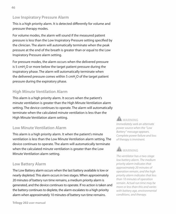
Trilogy 202 user manual
46
Low Inspiratory Pressure Alarm This is a high priority alarm. It is detected differently for volume and pressure therapy modes.
For volume modes, the alarm will sound if the measured patient pressure is less than the Low Inspiratory Pressure setting specified by the clinician. The alarm will automatically terminate when the peak pressure at the end of the breath is greater than or equal to the Low Inspiratory Pressure alarm setting.
For pressure modes, the alarm occurs when the delivered pressure is 5 cmH2O or more below the target patient pressure during the inspiratory phase. The alarm will automatically terminate when the delivered pressure comes within 5 cmH2O of the target patient pressure during the expiratory phase.
High Minute Ventilation Alarm This alarm is a high priority alarm. It occurs when the patient’s minute ventilation is greater than the High Minute Ventilation alarm setting. The device continues to operate. The alarm will automatically terminate when the calculated minute ventilation is less than the High Minute Ventilation alarm setting.
Low Minute Ventilation AlarmThis alarm is a high priority alarm. It when the patient’s minute ventilation is less than the Low Minute Ventilation alarm setting. The device continues to operate. The alarm will automatically terminate when the calculated minute ventilation is greater than the Low Minute Ventilation alarm setting.
Low Battery Alarm
The Low Battery alarm occurs when the last battery available is low or nearly depleted. This alarm occurs in two stages. When approximately 20 minutes of battery run time remains, a medium priority alarm is generated, and the device continues to operate. If no action is taken and the battery continues to deplete, the alarm escalates to a high priority alarm when approximately 10 minutes of battery run time remains.
WARNING Immediately seek an alternate power source when the “Low Battery” message appears. Complete power failure and loss of therapy is imminent.
WARNING
The ventilator has a two-stage low battery alarm. The medium priority alarm indicates that approximately 20 minutes of operation remain, and the high priority alarm indicates that less than 10 minutes of operation remain. Actual run time may be more or less than this and varies with battery age, environmental conditions, and therapy.
Chapter 3 Modes, Features, and Alarms
47
High Temperature Alarm This alarm occurs when the estimated patient airstream temperature or the ventilator internal temperature is too high. The alarm occurs in several stages. The ventilator continues to operate. Internal fans are started when the medium priority alarm is generated. If the condition causing the high temperature is not corrected and the temperature continues to rise, the alarm will escalate to the high priority alarm.
Replace Detachable Battery Alarm
The Replace Detachable Battery alarm occurs when the detachable battery is nearing the end of its useful life or a failure in the detachable battery that prevents it from charging or discharging has been detected.
The alarm occurs in several stages, from low to high priority. The device continues to operate when the alarm is the low priority alarm. If the alarm is reset without removing the battery, the alarm will be regenerated once every hour until the detachable battery is removed. The device continues to operate, the detachable battery is not used, and the power source is switched to the next available power source if the alarm is the high priority alarm.
Ventilator Service Recommended Alarm
This is a medium priority alarm. It occurs when the device has detected an error, but the error will not affect device performance or safety. The device continues to operate. Therapy and safety are not compromised. If the problem is not corrected, the device will generate a reminder message once per day, or whenever power is cycled, until the issue is corrected. Additionally, if the device is powered off, a reminder message will immediately appear when the device is turned on again.
Trilogy 202 user manual
48
AC Power Disconnected Alarm
This is a medium priority alarm. It occurs when the AC power source was lost, and the device has switched to an alternate power source (either a detachable or external battery, if connected, or the internal battery if no other source is available). The device continues to operate. If AC power returns, the ventilator will beep, but no message will appear on the display.
Keypad Stuck Alarm This is a low priority alarm. It occurs when one of the device buttons becomes stuck in the down (‘selected’) position, inside the case of the device.
Battery Discharging Stopped due to Temperature
Info MessageThis info message occurs when the detachable or internal battery becomes overheated while providing power for the device. The device continues to operate unless you are using an internal battery and have no other available power source. The battery is not used and the power source is switched to the next available power source.
Battery Not Charging due to Temperature Info Message This info message occurs when the detachable or internal battery becomes too hot while charging or the device was in too cold an environment before charging started. The device continues to operate. Battery charging stops until the battery cools or warms sufficiently.
Battery Not Charging Info Message
This info message occurs when the device has detected an error condition with the battery that prevents it from accepting a charge. The device continues to operate. Battery charging stops.
Chapter 3 Modes, Features, and Alarms
49
Check External Battery Info Message This info message occurs when a bad connection exists to the external battery or the external battery failed. The device continues to operate using power from the detachable battery, if available, or the internal battery.
Battery Depleted Info Message This info message occurs when the affected battery is fully depleted. The device continues to operate using the next available power source.
External Battery Disconnected Info Message
This info message occurs when the external battery power source is lost and the device has switched to an alternate power source (either a detachable battery, if connected, or the internal battery if no other source is available). If external battery power returns, the ventilator will beep, but no message will appear on the display.
Detachable Battery Disconnected Info MessageThis info message occurs when the detachable battery power source is lost and the device has switched to an alternate power source (the internal battery if no other source is available). If detachable battery power returns, the ventilator will beep, but no message will appear on the display.
Start On Battery Info MessageThis info message indicates that the ventilator has started on battery power and no AC power is available. The device operator should verify that this is what is wanted.
Card Error Info Message This info message occurs when an unusable SD card is inserted into the ventilator. The device continues to operate but data cannot be logged onto the SD card.

Trilogy 202 user manual
50
Chapter 4 Ventilator Setup
51
This chapter provides instructions on how to assemble the ventilator. It includes the following setup information:
Properly positioning the device •Installing the air filter •Supplying power to the device •Connecting the breathing circuit •Connecting a water trap (optional) •Connecting a remote alarm (optional) •
WARNING
Ventilator dependant patients should be continuously monitored by qualified personnel. These personnel should be prepared to provide alternate therapy in the event of ventilator failure or inoperative equipment.
WARNING
Do not use the ventilator on a patient until a system checkout has been performed. See Chapter 10 of this manual.
WARNING
For ventilator dependent patients, always have alternate ventilation equipment, such as a back-up ventilator, manual resuscitator, or similar device, available.
CAUTION
Do not operate the ventilator at temperatures below 5° C (41° F) or above 40° C (104° F).
Trilogy 202user manual
4. Ventilator Setup
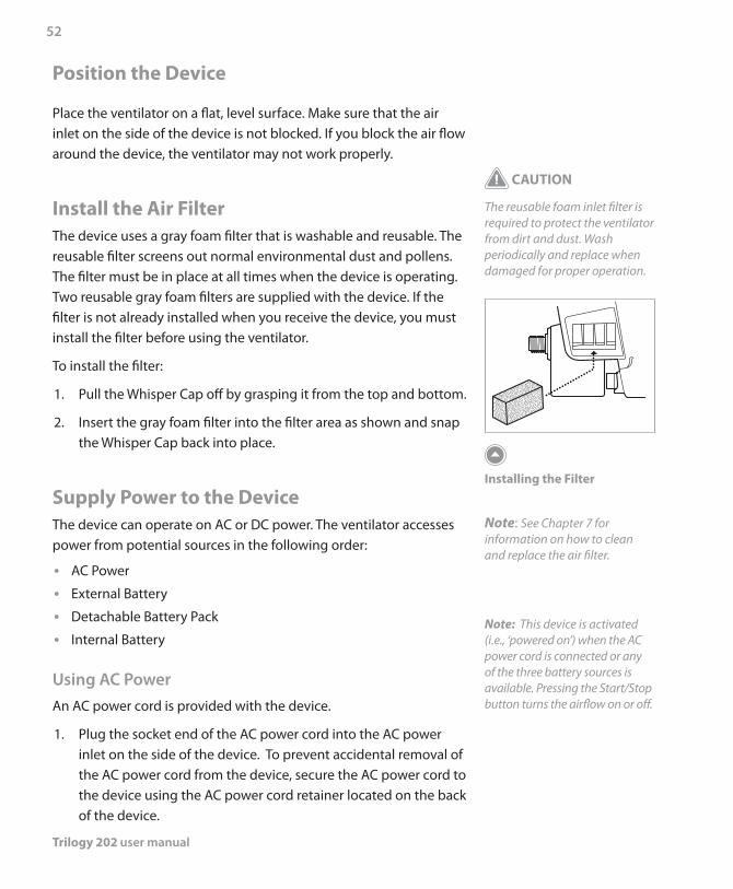
Trilogy 202 user manual
52
Position the Device
Place the ventilator on a flat, level surface. Make sure that the air inlet on the side of the device is not blocked. If you block the air flow around the device, the ventilator may not work properly.
Install the Air FilterThe device uses a gray foam filter that is washable and reusable. The reusable filter screens out normal environmental dust and pollens. The filter must be in place at all times when the device is operating. Two reusable gray foam filters are supplied with the device. If the filter is not already installed when you receive the device, you must install the filter before using the ventilator.
To install the filter:
1. Pull the Whisper Cap off by grasping it from the top and bottom.
2. Insert the gray foam filter into the filter area as shown and snap the Whisper Cap back into place.
Supply Power to the DeviceThe device can operate on AC or DC power. The ventilator accesses power from potential sources in the following order:
AC Power •External Battery •Detachable Battery Pack •Internal Battery •
Using AC PowerAn AC power cord is provided with the device.
1. Plug the socket end of the AC power cord into the AC power inlet on the side of the device. To prevent accidental removal of the AC power cord from the device, secure the AC power cord to the device using the AC power cord retainer located on the back of the device.
CAUTION
The reusable foam inlet filter is required to protect the ventilator from dirt and dust. Wash periodically and replace when damaged for proper operation.
Installing the Filter
Note: See Chapter 7 for information on how to clean and replace the air filter.
Note: This device is activated (i.e., ‘powered on’) when the AC power cord is connected or any of the three battery sources is available. Pressing the Start/Stop button turns the airflow on or off.
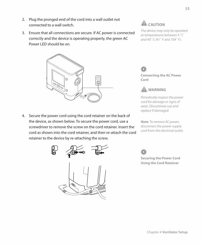
Chapter 4 Ventilator Setup
53
CAUTIONThe device may only be operated at temperatures between 5˚ C and 40˚ C (41˚ F and 104˚ F).
Connecting the AC Power Cord
WARNING
Periodically inspect the power cord for damage or signs of wear. Discontinue use and replace if damaged.
Note: To remove AC power, disconnect the power supply cord from the electrical outlet.
Securing the Power Cord Using the Cord Retainer
2. Plug the pronged end of the cord into a wall outlet not connected to a wall switch.
3. Ensure that all connections are secure. If AC power is connected correctly and the device is operating properly, the green AC Power LED should be on.
4. Secure the power cord using the cord retainer on the back of the device, as shown below. To secure the power cord, use a screwdriver to remove the screw on the cord retainer. Insert the cord as shown into the cord retainer, and then re-attach the cord retainer to the device by re-attaching the screw.
Trilogy 202 user manual
54
CAUTIONDo not use the same external battery to operate both the ventilator and any other equipment such as power chairs.
CAUTION
An external battery should only be connected to the ventilator using the Respironics Trilogy External Battery Cable. This cable is fused, pre-wired and properly terminated to ensure safe connection to a standard deep cycle lead acid battery. Use of any other adapter or cable may cause improper operation of the ventilator.
Using DC PowerYou can operate the ventilator using an external battery, detachable battery, or the internal battery.
External Battery
The ventilator can operate from a 12 VDC deep cycle marine-type (lead acid) battery using the Philips Respironics Trilogy External Battery Cable. This cable is pre-wired and properly terminated to ensure safe connection of an external battery to the ventilator. Battery operating time depends on the characteristics of the battery and usage of the device.
Due to a variety of factors, including battery chemistry, battery age, and use profile, the capacity of the external battery as shown on the device display is only an estimate of the actual remaining capacity.
Refer to the instructions supplied with the Philips Respironics Trilogy External Battery Cable for detailed information on how to operate the device using an external battery.
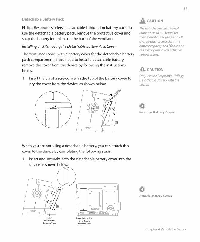
Chapter 4 Ventilator Setup
55
Detachable Battery Pack
Philips Respironics offers a detachable Lithium-Ion battery pack. To use the detachable battery pack, remove the protective cover and snap the battery into place on the back of the ventilator.
Installing and Removing the Detachable Battery Pack Cover
The ventilator comes with a battery cover for the detachable battery pack compartment. If you need to install a detachable battery, remove the cover from the device by following the instructions below.
1. Insert the tip of a screwdriver in the top of the battery cover to pry the cover from the device, as shown below.
When you are not using a detachable battery, you can attach this cover to the device by completing the following steps:
1. Insert and securely latch the detachable battery cover into the device as shown below.
Properly InstalledDetachable
Battery Cover
InsertDetachable
Battery Cover
CAUTION
The detachable and internal batteries wear out based on the amount of use (hours or full charge-discharge cycles). The battery capacity and life are also reduced by operation at higher temperatures.
CAUTION
Only use the Respironics Trilogy Detachable Battery with the device.
Remove Battery Cover
Attach Battery Cover
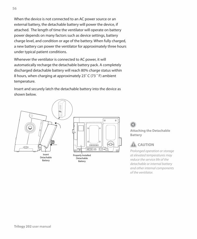
Trilogy 202 user manual
56
When the device is not connected to an AC power source or an external battery, the detachable battery will power the device, if attached. The length of time the ventilator will operate on battery power depends on many factors such as device settings, battery charge level, and condition or age of the battery. When fully charged, a new battery can power the ventilator for approximately three hours under typical patient conditions.
Whenever the ventilator is connected to AC power, it will automatically recharge the detachable battery pack. A completely discharged detachable battery will reach 80% charge status within 8 hours, when charging at approximately 23˚ C (73 ˚ F) ambient temperature.
Insert and securely latch the detachable battery into the device as shown below.
Properly InstalledDetachable
Battery
InsertDetachable
Battery
Attaching the Detachable Battery
CAUTION
Prolonged operation or storage at elevated temperatures may reduce the service life of the detachable or internal battery and other internal components of the ventilator.
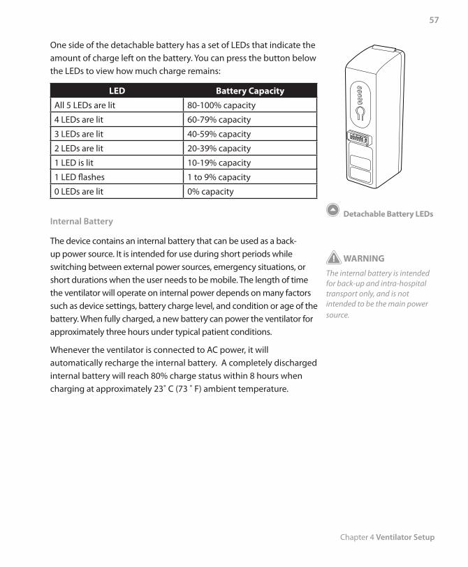
Chapter 4 Ventilator Setup
57
One side of the detachable battery has a set of LEDs that indicate the amount of charge left on the battery. You can press the button below the LEDs to view how much charge remains:
LED Battery Capacity
All 5 LEDs are lit 80-100% capacity
4 LEDs are lit 60-79% capacity
3 LEDs are lit 40-59% capacity
2 LEDs are lit 20-39% capacity
1 LED is lit 10-19% capacity
1 LED flashes 1 to 9% capacity
0 LEDs are lit 0% capacity
Internal Battery
The device contains an internal battery that can be used as a back-up power source. It is intended for use during short periods while switching between external power sources, emergency situations, or short durations when the user needs to be mobile. The length of time the ventilator will operate on internal power depends on many factors such as device settings, battery charge level, and condition or age of the battery. When fully charged, a new battery can power the ventilator for approximately three hours under typical patient conditions.
Whenever the ventilator is connected to AC power, it will automatically recharge the internal battery. A completely discharged internal battery will reach 80% charge status within 8 hours when charging at approximately 23˚ C (73 ˚ F) ambient temperature.
Detachable Battery LEDs
WARNING
The internal battery is intended for back-up and intra-hospital transport only, and is not intended to be the main power source.
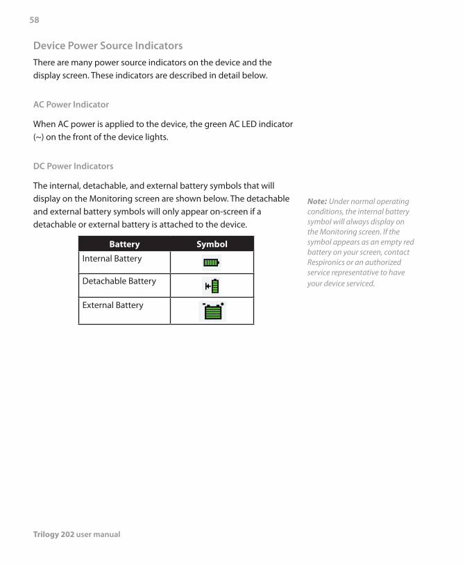
Trilogy 202 user manual
58
Device Power Source IndicatorsThere are many power source indicators on the device and the display screen. These indicators are described in detail below.
AC Power Indicator
When AC power is applied to the device, the green AC LED indicator (~) on the front of the device lights.
DC Power Indicators
The internal, detachable, and external battery symbols that will display on the Monitoring screen are shown below. The detachable and external battery symbols will only appear on-screen if a detachable or external battery is attached to the device.
Battery Symbol
Internal Battery
Detachable Battery
External Battery
Note: Under normal operating conditions, the internal battery symbol will always display on the Monitoring screen. If the symbol appears as an empty red battery on your screen, contact Respironics or an authorized service representative to have your device serviced.
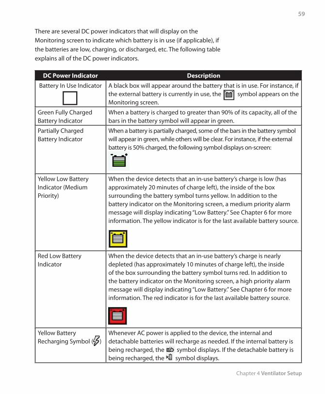
Chapter 4 Ventilator Setup
59
There are several DC power indicators that will display on the Monitoring screen to indicate which battery is in use (if applicable), if the batteries are low, charging, or discharged, etc. The following table explains all of the DC power indicators.
DC Power Indicator Description
Battery In Use Indicator A black box will appear around the battery that is in use. For instance, if the external battery is currently in use, the symbol appears on the Monitoring screen.
Green Fully Charged Battery Indicator
When a battery is charged to greater than 90% of its capacity, all of the bars in the battery symbol will appear in green.
Partially Charged Battery Indicator
When a battery is partially charged, some of the bars in the battery symbol will appear in green, while others will be clear. For instance, if the external battery is 50% charged, the following symbol displays on-screen:
Yellow Low Battery Indicator (Medium Priority)
When the device detects that an in-use battery’s charge is low (has approximately 20 minutes of charge left), the inside of the box surrounding the battery symbol turns yellow. In addition to the battery indicator on the Monitoring screen, a medium priority alarm message will display indicating “Low Battery.” See Chapter 6 for more information. The yellow indicator is for the last available battery source.
Red Low Battery Indicator
When the device detects that an in-use battery’s charge is nearly depleted (has approximately 10 minutes of charge left), the inside of the box surrounding the battery symbol turns red. In addition to the battery indicator on the Monitoring screen, a high priority alarm message will display indicating “Low Battery.” See Chapter 6 for more information. The red indicator is for the last available battery source.
Yellow Battery Recharging Symbol ( )
Whenever AC power is applied to the device, the internal and detachable batteries will recharge as needed. If the internal battery is being recharged, the symbol displays. If the detachable battery is being recharged, the symbol displays.
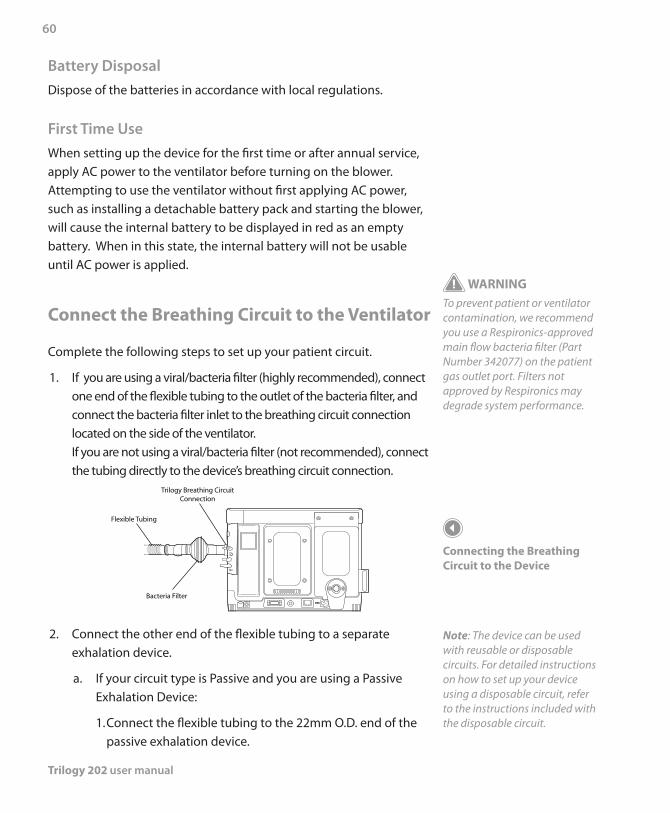
Trilogy 202 user manual
60
Battery DisposalDispose of the batteries in accordance with local regulations.
First Time UseWhen setting up the device for the first time or after annual service, apply AC power to the ventilator before turning on the blower. Attempting to use the ventilator without first applying AC power, such as installing a detachable battery pack and starting the blower, will cause the internal battery to be displayed in red as an empty battery. When in this state, the internal battery will not be usable until AC power is applied.
Connect the Breathing Circuit to the Ventilator
Complete the following steps to set up your patient circuit.
1. If you are using a viral/bacteria filter (highly recommended), connect one end of the flexible tubing to the outlet of the bacteria filter, and connect the bacteria filter inlet to the breathing circuit connection located on the side of the ventilator. If you are not using a viral/bacteria filter (not recommended), connect the tubing directly to the device’s breathing circuit connection.
Bacteria Filter
Flexible Tubing
Trilogy Breathing CircuitConnection
2. Connect the other end of the flexible tubing to a separate exhalation device.
a. If your circuit type is Passive and you are using a Passive Exhalation Device:
1. Connect the flexible tubing to the 22mm O.D. end of the passive exhalation device.
WARNINGTo prevent patient or ventilator contamination, we recommend you use a Respironics-approved main flow bacteria filter (Part Number 342077) on the patient gas outlet port. Filters not approved by Respironics may degrade system performance.
Connecting the Breathing Circuit to the Device
Note: The device can be used with reusable or disposable circuits. For detailed instructions on how to set up your device using a disposable circuit, refer to the instructions included with the disposable circuit.
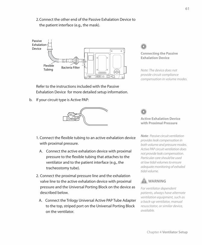
Chapter 4 Ventilator Setup
61
2. Connect the other end of the Passive Exhalation Device to the patient interface (e.g., the mask).
FlexibleTubing
PassiveExhalationDevice
Bacteria Filter
Refer to the instructions included with the Passive Exhalation Device for more detailed setup information.
b. If your circuit type is Active PAP:
1. Connect the flexible tubing to an active exhalation device with proximal pressure.
A. Connect the active exhalation device with proximal pressure to the flexible tubing that attaches to the ventilator and to the patient interface (e.g., the tracheostomy tube).
2. Connect the proximal pressure line and the exhalation valve line to the active exhalation device with proximal pressure and the Universal Porting Block on the device as described below.
A. Connect the Trilogy Universal Active PAP Tube Adapter to the top, striped port on the Universal Porting Block on the ventilator.
Connecting the Passive Exhalation Device
Note: The device does not provide circuit compliance compensation in volume modes.
Active Exhalation Device with Proximal Pressure
Note: Passive circuit ventilation provides leak compensation in both volume and pressure modes. Active PAP circuit ventilation does not provide leak compensation. Particular care should be used at low tidal volumes to ensure adequate monitoring of exhaled tidal volume.
WARNING
For ventilator dependent patients, always have alternate ventilation equipment, such as a back-up ventilator, manual resuscitator, or similar device, available.
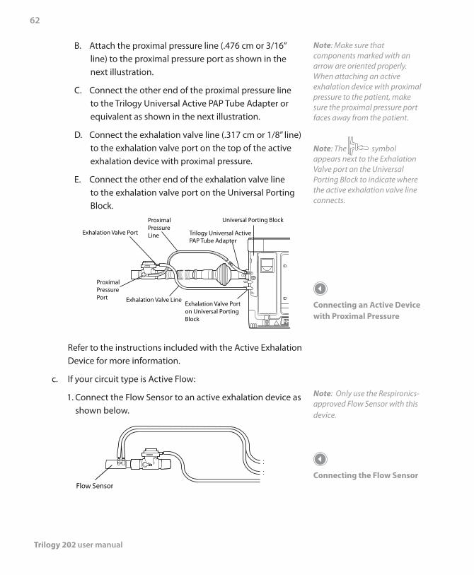
Trilogy 202 user manual
62
B. Attach the proximal pressure line (.476 cm or 3/16” line) to the proximal pressure port as shown in the next illustration.
C. Connect the other end of the proximal pressure line to the Trilogy Universal Active PAP Tube Adapter or equivalent as shown in the next illustration.
D. Connect the exhalation valve line (.317 cm or 1/8” line) to the exhalation valve port on the top of the active exhalation device with proximal pressure.
E. Connect the other end of the exhalation valve line to the exhalation valve port on the Universal Porting Block.
Universal Porting Block
Exhalation Valve Line
Exhalation Valve Port
Proximal PressureLine
Proximal PressurePort
Exhalation Valve Porton Universal Porting Block
Trilogy Universal Active PAP Tube Adapter
Refer to the instructions included with the Active Exhalation Device for more information.
c. If your circuit type is Active Flow:
1. Connect the Flow Sensor to an active exhalation device as shown below.
Flow Sensor
Note: Make sure that components marked with an arrow are oriented properly. When attaching an active exhalation device with proximal pressure to the patient, make sure the proximal pressure port faces away from the patient.
Note: The symbol appears next to the Exhalation Valve port on the Universal Porting Block to indicate where the active exhalation valve line connects.
Connecting an Active Device with Proximal Pressure
Note: Only use the Respironics-approved Flow Sensor with this device.
Connecting the Flow Sensor
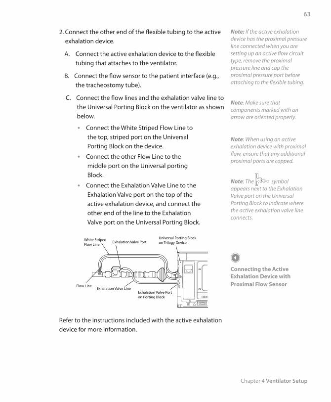
Chapter 4 Ventilator Setup
63
2. Connect the other end of the flexible tubing to the active exhalation device.
A. Connect the active exhalation device to the flexible tubing that attaches to the ventilator.
B. Connect the flow sensor to the patient interface (e.g., the tracheostomy tube).
C. Connect the flow lines and the exhalation valve line to the Universal Porting Block on the ventilator as shown below.
Connect the White Striped Flow Line to •the top, striped port on the Universal Porting Block on the device.
Connect the other Flow Line to the •middle port on the Universal porting Block.
Connect the Exhalation Valve Line to the •Exhalation Valve port on the top of the active exhalation device, and connect the other end of the line to the Exhalation Valve port on the Universal Porting Block.
Exhalation Valve LineFlow Line
Exhalation Valve Porton Porting Block
Universal Porting Blockon Trilogy Device
White StripedFlow Line
Exhalation Valve Port
Refer to the instructions included with the active exhalation device for more information.
Note: If the active exhalation device has the proximal pressure line connected when you are setting up an active flow circuit type, remove the proximal pressure line and cap the proximal pressure port before attaching to the flexible tubing.
Note: Make sure that components marked with an arrow are oriented properly.
Note: When using an active exhalation device with proximal flow, ensure that any additional proximal ports are capped.
Note: The symbol appears next to the Exhalation Valve port on the Universal Porting Block to indicate where the active exhalation valve line connects.
Connecting the Active Exhalation Device with Proximal Flow Sensor
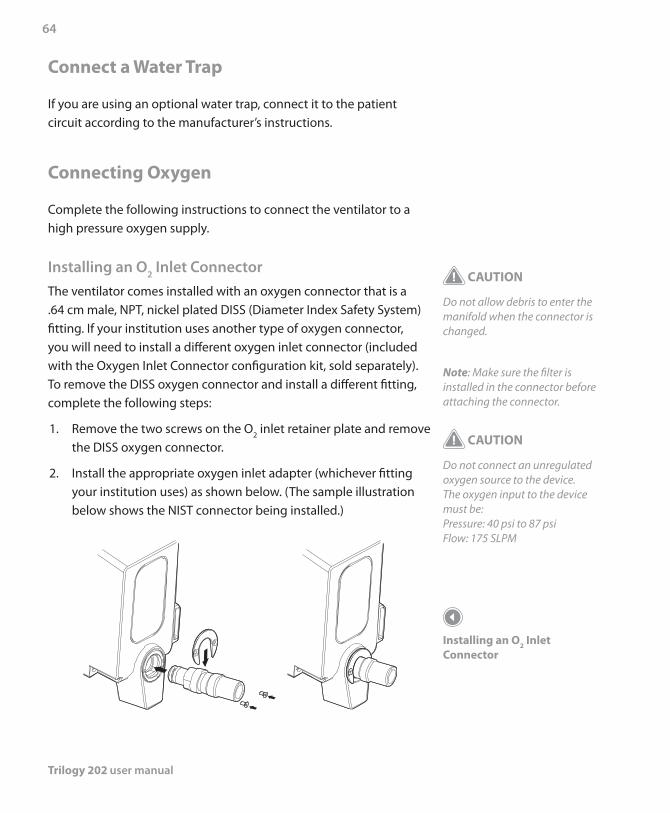
Trilogy 202 user manual
64
Connect a Water Trap
If you are using an optional water trap, connect it to the patient circuit according to the manufacturer’s instructions.
Connecting Oxygen
Complete the following instructions to connect the ventilator to a high pressure oxygen supply.
Installing an O2 Inlet ConnectorThe ventilator comes installed with an oxygen connector that is a .64 cm male, NPT, nickel plated DISS (Diameter Index Safety System) fitting. If your institution uses another type of oxygen connector, you will need to install a different oxygen inlet connector (included with the Oxygen Inlet Connector configuration kit, sold separately). To remove the DISS oxygen connector and install a different fitting, complete the following steps:
1. Remove the two screws on the O2 inlet retainer plate and remove the DISS oxygen connector.
2. Install the appropriate oxygen inlet adapter (whichever fitting your institution uses) as shown below. (The sample illustration below shows the NIST connector being installed.)
CAUTION
Do not allow debris to enter the manifold when the connector is changed.
Note: Make sure the filter is installed in the connector before attaching the connector.
CAUTION
Do not connect an unregulated oxygen source to the device. The oxygen input to the device must be: Pressure: 40 psi to 87 psi Flow: 175 SLPM
Installing an O2 Inlet Connector
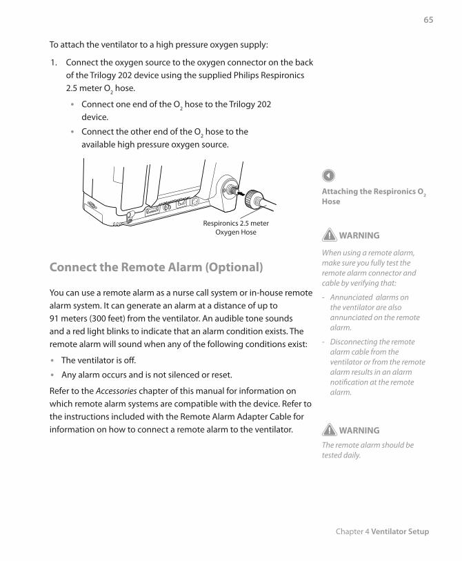
Chapter 4 Ventilator Setup
65
To attach the ventilator to a high pressure oxygen supply:
1. Connect the oxygen source to the oxygen connector on the back of the Trilogy 202 device using the supplied Philips Respironics 2.5 meter O2 hose.
Connect one end of the O • 2 hose to the Trilogy 202 device.
Connect the other end of the O • 2 hose to the available high pressure oxygen source.
Respironics 2.5 meter Oxygen Hose
Connect the Remote Alarm (Optional)
You can use a remote alarm as a nurse call system or in-house remote alarm system. It can generate an alarm at a distance of up to 91 meters (300 feet) from the ventilator. An audible tone sounds and a red light blinks to indicate that an alarm condition exists. The remote alarm will sound when any of the following conditions exist:
The ventilator is off. •Any alarm occurs and is not silenced or reset. •
Refer to the Accessories chapter of this manual for information on which remote alarm systems are compatible with the device. Refer to the instructions included with the Remote Alarm Adapter Cable for information on how to connect a remote alarm to the ventilator.
Attaching the Respironics O2 Hose
WARNING
When using a remote alarm, make sure you fully test the remote alarm connector and cable by verifying that:
- Annunciated alarms on the ventilator are also annunciated on the remote alarm.
- Disconnecting the remote alarm cable from the ventilator or from the remote alarm results in an alarm notification at the remote alarm.
WARNING
The remote alarm should be tested daily.

Trilogy 202 user manual
66
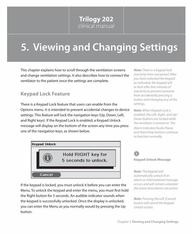
Chapter 5 Viewing and Changing Settings
67
This chapter explains how to scroll through the ventilation screens and change ventilation settings. It also describes how to connect the ventilator to the patient once the settings are complete.
Keypad Lock Feature
There is a Keypad Lock feature that users can enable from the Options menu. It is intended to prevent accidental changes to device settings. This feature will lock the navigation keys (Up, Down, Left, and Right keys). If the Keypad Lock is enabled, a Keypad Unlock message will display on the bottom of the screen any time you press one of the navigation keys, as shown below.
If the keypad is locked, you must unlock it before you can enter the Menu. To unlock the keypad and enter the menu, you must first hold the Right button for 5 seconds. An audible indicator sounds when the keypad is successfully unlocked. Once the display is unlocked, you can enter the Menu as you normally would by pressing the Up button.
Note: There is a keypad lock inactivity time-out period. After you have unlocked the keypad as indicated, the keypad will re-lock after five minutes of inactivity to prevent someone from accidentally pressing a button and changing any of the settings.
Note: When Keypad Lock is enabled, the Left, Right, and Up/Down buttons are locked while the ventilator is turned on. The Alarm Indicator/Audio Pause and Start/Stop buttons continue to function normally.
Keypad Unlock Message
Note: The keypad will automatically unlock if an alarm or informational message occurs and will remain unlocked the entire time alarms are active.
Note: Pressing the Left (Cancel) button will cancel the Keypad Unlock action.
Trilogy 202clinical manual
5. Viewing and Changing Settings
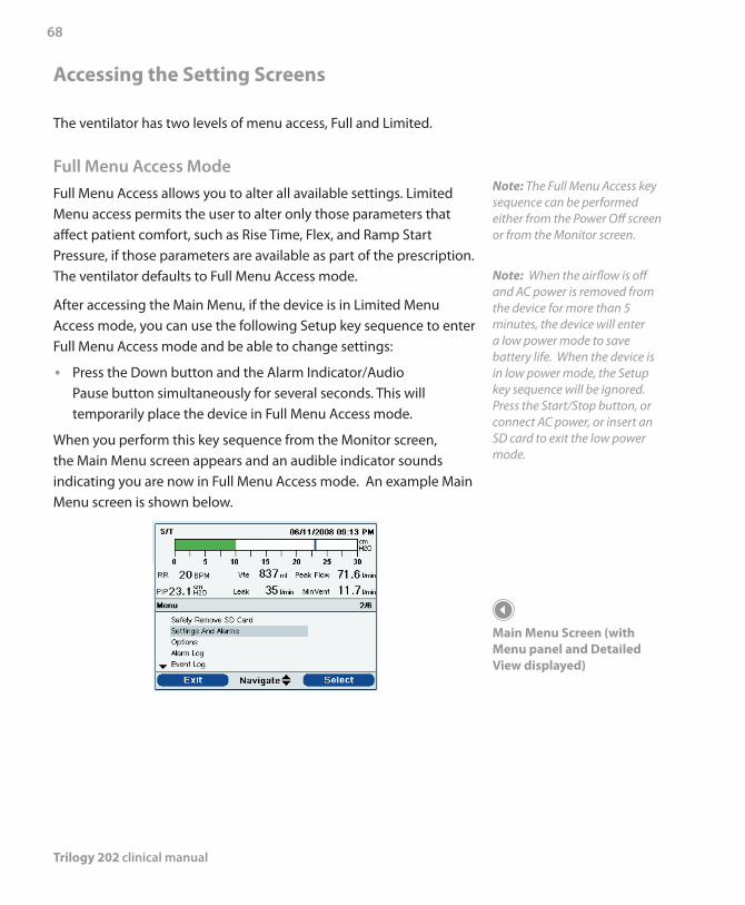
Trilogy 202 clinical manual
68
Accessing the Setting Screens
The ventilator has two levels of menu access, Full and Limited.
Full Menu Access ModeFull Menu Access allows you to alter all available settings. Limited Menu access permits the user to alter only those parameters that affect patient comfort, such as Rise Time, Flex, and Ramp Start Pressure, if those parameters are available as part of the prescription. The ventilator defaults to Full Menu Access mode.
After accessing the Main Menu, if the device is in Limited Menu Access mode, you can use the following Setup key sequence to enter Full Menu Access mode and be able to change settings:
Press the Down button and the • Alarm Indicator/Audio Pause button simultaneously for several seconds. This will temporarily place the device in Full Menu Access mode.
When you perform this key sequence from the Monitor screen, the Main Menu screen appears and an audible indicator sounds indicating you are now in Full Menu Access mode. An example Main Menu screen is shown below.
Note: The Full Menu Access key sequence can be performed either from the Power Off screen or from the Monitor screen.
Note: When the airflow is off and AC power is removed from the device for more than 5 minutes, the device will enter a low power mode to save battery life. When the device is in low power mode, the Setup key sequence will be ignored. Press the Start/Stop button, or connect AC power, or insert an SD card to exit the low power mode.
Main Menu Screen (with Menu panel and Detailed View displayed)
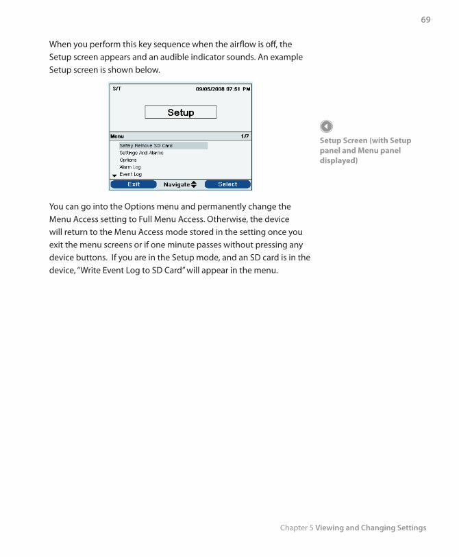
Chapter 5 Viewing and Changing Settings
69
When you perform this key sequence when the airflow is off, the Setup screen appears and an audible indicator sounds. An example Setup screen is shown below.
You can go into the Options menu and permanently change the Menu Access setting to Full Menu Access. Otherwise, the device will return to the Menu Access mode stored in the setting once you exit the menu screens or if one minute passes without pressing any device buttons. If you are in the Setup mode, and an SD card is in the device, “Write Event Log to SD Card” will appear in the menu.
Setup Screen (with Setup panel and Menu panel displayed)
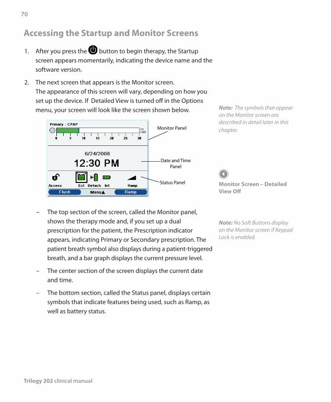
Trilogy 202 clinical manual
70
Accessing the Startup and Monitor Screens
1. After you press the button to begin therapy, the Startup screen appears momentarily, indicating the device name and the software version.
2. The next screen that appears is the Monitor screen. The appearance of this screen will vary, depending on how you set up the device. If Detailed View is turned off in the Options menu, your screen will look like the screen shown below.
Monitor Panel
Date and TimePanel
Status Panel
– The top section of the screen, called the Monitor panel, shows the therapy mode and, if you set up a dual prescription for the patient, the Prescription indicator appears, indicating Primary or Secondary prescription. The patient breath symbol also displays during a patient-triggered breath, and a bar graph displays the current pressure level.
– The center section of the screen displays the current date and time.
– The bottom section, called the Status panel, displays certain symbols that indicate features being used, such as Ramp, as well as battery status.
Note: The symbols that appear on the Monitor screen are described in detail later in this chapter.
Monitor Screen – Detailed View Off
Note: No Soft Buttons display on the Monitor screen if Keypad Lock is enabled.
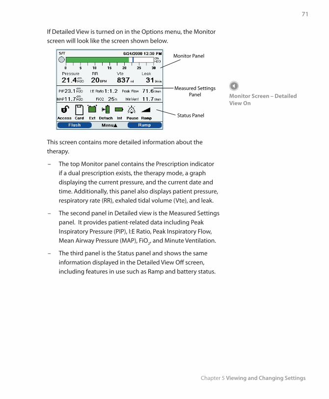
Chapter 5 Viewing and Changing Settings
71
Monitor Screen – Detailed View On
If Detailed View is turned on in the Options menu, the Monitor screen will look like the screen shown below.
Monitor Panel
Measured SettingsPanel
Status Panel
This screen contains more detailed information about the therapy.
– The top Monitor panel contains the Prescription indicator if a dual prescription exists, the therapy mode, a graph displaying the current pressure, and the current date and time. Additionally, this panel also displays patient pressure, respiratory rate (RR), exhaled tidal volume (Vte), and leak.
– The second panel in Detailed view is the Measured Settings panel. It provides patient-related data including Peak Inspiratory Pressure (PIP), I:E Ratio, Peak Inspiratory Flow, Mean Airway Pressure (MAP), FiO2, and Minute Ventilation.
– The third panel is the Status panel and shows the same information displayed in the Detailed View Off screen, including features in use such as Ramp and battery status.
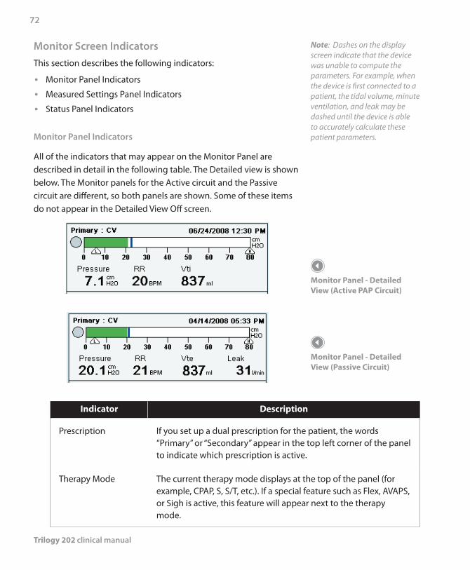
Trilogy 202 clinical manual
72
Monitor Screen IndicatorsThis section describes the following indicators:
Monitor Panel Indicators •Measured Settings Panel Indicators •Status Panel Indicators •
Monitor Panel Indicators
All of the indicators that may appear on the Monitor Panel are described in detail in the following table. The Detailed view is shown below. The Monitor panels for the Active circuit and the Passive circuit are different, so both panels are shown. Some of these items do not appear in the Detailed View Off screen.
Indicator Description
Prescription If you set up a dual prescription for the patient, the words “Primary” or “Secondary” appear in the top left corner of the panel to indicate which prescription is active.
Therapy Mode The current therapy mode displays at the top of the panel (for example, CPAP, S, S/T, etc.). If a special feature such as Flex, AVAPS, or Sigh is active, this feature will appear next to the therapy mode.
Note: Dashes on the display screen indicate that the device was unable to compute the parameters. For example, when the device is first connected to a patient, the tidal volume, minute ventilation, and leak may be dashed until the device is able to accurately calculate these patient parameters.
Monitor Panel - Detailed View (Active PAP Circuit)
Monitor Panel - Detailed View (Passive Circuit)
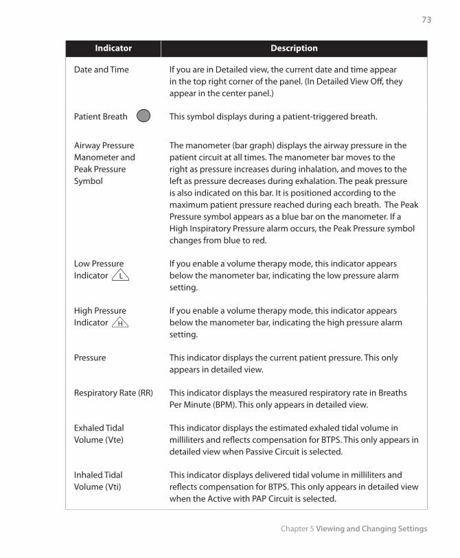
Chapter 5 Viewing and Changing Settings
73
Indicator Description
Date and Time If you are in Detailed view, the current date and time appear in the top right corner of the panel. (In Detailed View Off, they appear in the center panel.)
Patient Breath This symbol displays during a patient-triggered breath.
Airway Pressure Manometer and Peak Pressure Symbol
The manometer (bar graph) displays the airway pressure in the patient circuit at all times. The manometer bar moves to the right as pressure increases during inhalation, and moves to the left as pressure decreases during exhalation. The peak pressure is also indicated on this bar. It is positioned according to the maximum patient pressure reached during each breath. The Peak Pressure symbol appears as a blue bar on the manometer. If a High Inspiratory Pressure alarm occurs, the Peak Pressure symbol changes from blue to red.
Low Pressure Indicator L
If you enable a volume therapy mode, this indicator appears below the manometer bar, indicating the low pressure alarm setting.
High Pressure Indicator H
If you enable a volume therapy mode, this indicator appears below the manometer bar, indicating the high pressure alarm setting.
Pressure This indicator displays the current patient pressure. This only appears in detailed view.
Respiratory Rate (RR) This indicator displays the measured respiratory rate in Breaths Per Minute (BPM). This only appears in detailed view.
Exhaled Tidal Volume (Vte)
This indicator displays the estimated exhaled tidal volume in milliliters and reflects compensation for BTPS. This only appears in detailed view when Passive Circuit is selected.
Inhaled Tidal Volume (Vti)
This indicator displays delivered tidal volume in milliliters and reflects compensation for BTPS. This only appears in detailed view when the Active with PAP Circuit is selected.
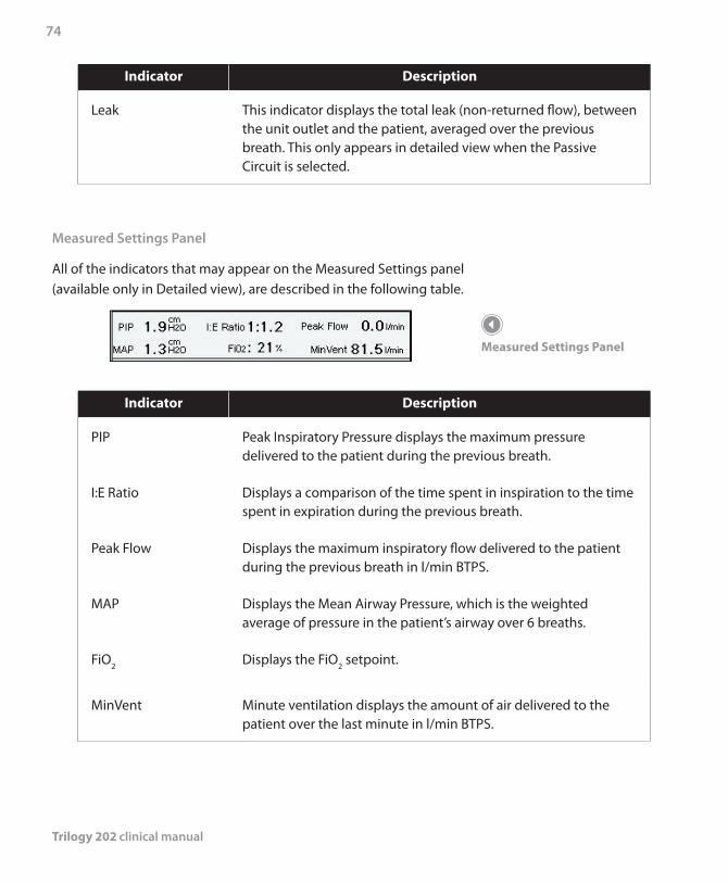
Trilogy 202 clinical manual
74
Indicator Description
Leak This indicator displays the total leak (non-returned flow), between the unit outlet and the patient, averaged over the previous breath. This only appears in detailed view when the Passive Circuit is selected.
Measured Settings Panel
All of the indicators that may appear on the Measured Settings panel (available only in Detailed view), are described in the following table.
Indicator Description
PIP Peak Inspiratory Pressure displays the maximum pressure delivered to the patient during the previous breath.
I:E Ratio Displays a comparison of the time spent in inspiration to the time spent in expiration during the previous breath.
Peak Flow Displays the maximum inspiratory flow delivered to the patient during the previous breath in l/min BTPS.
MAP Displays the Mean Airway Pressure, which is the weighted average of pressure in the patient’s airway over 6 breaths.
FiO2 Displays the FiO2 setpoint.
MinVent Minute ventilation displays the amount of air delivered to the patient over the last minute in l/min BTPS.
Measured Settings Panel
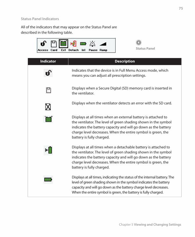
Chapter 5 Viewing and Changing Settings
75
Status Panel Indicators
All of the indicators that may appear on the Status Panel are described in the following table.
Indicator Description
Indicates that the device is in Full Menu Access mode, which means you can adjust all prescription settings.
Displays when a Secure Digital (SD) memory card is inserted in the ventilator.
Displays when the ventilator detects an error with the SD card.
Displays at all times when an external battery is attached to the ventilator. The level of green shading shown in the symbol indicates the battery capacity and will go down as the battery charge level decreases. When the entire symbol is green, the battery is fully charged.
Displays at all times when a detachable battery is attached to the ventilator. The level of green shading shown in the symbol indicates the battery capacity and will go down as the battery charge level decreases. When the entire symbol is green, the battery is fully charged.
Displays at all times, indicating the status of the internal battery. The level of green shading shown in the symbol indicates the battery capacity and will go down as the battery charge level decreases. When the entire symbol is green, the battery is fully charged.
Status Panel
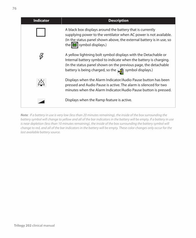
Trilogy 202 clinical manual
76
Indicator Description
A black box displays around the battery that is currently supplying power to the ventilator when AC power is not available. (In the status panel shown above, the external battery is in use, so the symbol displays.)
A yellow lightning bolt symbol displays with the Detachable or Internal battery symbol to indicate when the battery is charging. (In the status panel shown on the previous page, the detachable battery is being charged, so the symbol displays.)
Displays when the Alarm Indicator/Audio Pause button has been pressed and Audio Pause is active. The alarm is silenced for two minutes when the Alarm Indicator/Audio Pause button is pressed.
Displays when the Ramp feature is active.
Note: If a battery in use is very low (less than 20 minutes remaining), the inside of the box surrounding the battery symbol will change to yellow and all of the bar indicators in the battery will be empty. If a battery in use is near depletion (less than 10 minutes remaining), the inside of the box surrounding the battery symbol will change to red, and all of the bar indicators in the battery will be empty. These color changes only occur for the last available battery source.
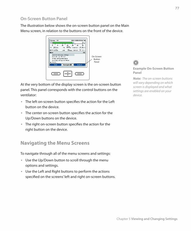
Chapter 5 Viewing and Changing Settings
77
On-Screen Button PanelThe illustration below shows the on-screen button panel on the Main Menu screen, in relation to the buttons on the front of the device.
On-Screen ButtonPanel
At the very bottom of the display screen is the on-screen button panel. This panel corresponds with the control buttons on the ventilator:
The left on-screen button specifies the action for the Left •button on the device.
The center on-screen button specifies the action for the •Up/Down buttons on the device.
The right on-screen button specifies the action for the •right button on the device.
Navigating the Menu Screens
To navigate through all of the menu screens and settings:
Use the Up/Down button to scroll through the menu •options and settings.
Use the Left and Right buttons to perform the actions •specified on the screens’ left and right on-screen buttons.
Example On-Screen Button Panel
Note: The on-screen buttons will vary depending on which screen is displayed and what settings are enabled on your device.
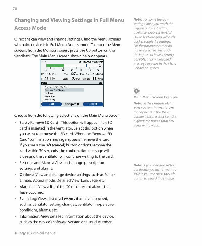
Trilogy 202 clinical manual
78
Changing and Viewing Settings in Full Menu Access Mode
Clinicians can view and change settings using the Menu screens when the device is in Full Menu Access mode. To enter the Menu screens from the Monitor screen, press the Up button on the ventilator. The Main Menu screen shown below appears.
Choose from the following selections on the Main Menu screen:
Safely Remove SD Card - This option will appear if an SD •card is inserted in the ventilator. Select this option when you want to remove the SD card. When the “Remove SD Card” confirmation message appears, remove the card. If you press the left (cancel) button or don’t remove the card within 30 seconds, the confirmation message will close and the ventilator will continue writing to the card.
Settings and Alarms: View and change prescription •settings and alarms.
Options: View and change device settings, such as Full or •Limited Access mode, Detailed View, Language, etc.
Alarm Log: View a list of the 20 most recent alarms that •have occurred.
Event Log: View a list of all events that have occurred, •such as ventilator setting changes, ventilator inoperative conditions, alarms, etc.
Information: View detailed information about the device, •such as the device’s software version and serial number.
Note: For some therapy settings, once you reach the highest or lowest setting available, pressing the Up/ Down button again will cycle back through the settings. For the parameters that do not wrap, when you reach the highest or lowest setting possible, a “Limit Reached” message appears in the Menu Banner on-screen.
Main Menu Screen Example
Note: In the example Main Menu screen shown, the 2/6 that appears in the Menu banner indicates that item 2 is highlighted from a total of 6 items in the menu.
Note: If you change a setting but decide you do not want to save it, you can press the Left button to cancel the change.
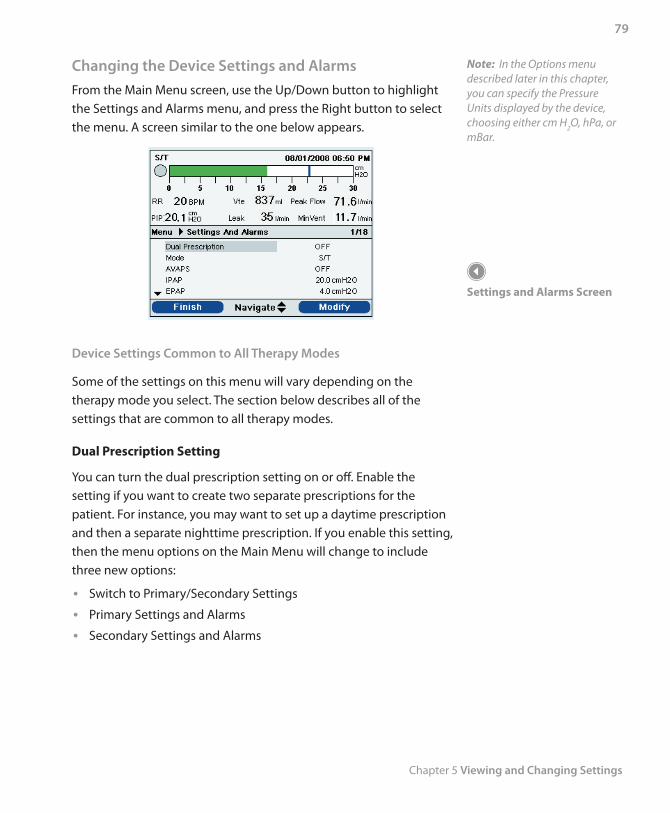
Chapter 5 Viewing and Changing Settings
79
Changing the Device Settings and AlarmsFrom the Main Menu screen, use the Up/Down button to highlight the Settings and Alarms menu, and press the Right button to select the menu. A screen similar to the one below appears.
Device Settings Common to All Therapy Modes
Some of the settings on this menu will vary depending on the therapy mode you select. The section below describes all of the settings that are common to all therapy modes.
Dual Prescription Setting
You can turn the dual prescription setting on or off. Enable the setting if you want to create two separate prescriptions for the patient. For instance, you may want to set up a daytime prescription and then a separate nighttime prescription. If you enable this setting, then the menu options on the Main Menu will change to include three new options:
Switch to Primary/Secondary Settings •Primary Settings and Alarms •Secondary Settings and Alarms •
Settings and Alarms Screen
Note: In the Options menu described later in this chapter, you can specify the Pressure Units displayed by the device, choosing either cm H2O, hPa, or mBar.
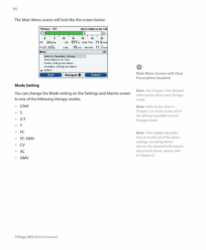
Trilogy 202 clinical manual
80
Main Menu Screen with Dual Prescription Enabled
Note: See Chapter 3 for detailed information about each therapy mode.
Note: Refer to the chart in Chapter 3 to easily review all of the settings available in each therapy mode.
Note: This chapter describes how to enable all of the device settings, including device alarms. For detailed information about each alarm, please refer to Chapter 6.
The Main Menu screen will look like the screen below.
Mode Setting
You can change the Mode setting on the Settings and Alarms screen to one of the following therapy modes:
CPAP •S •S/T •T •PC •PC-SIMV •CV •AC •SIMV •
Chapter 5 Viewing and Changing Settings
81
Circuit Type
There are three circuit types you can select:
Passive •Active PAP •Active Flow •
The Passive circuit type uses a passive exhalation device. The Active PAP circuit type uses an active exhalation device with a proximal air pressure sensing connection. The Active Flow circuit type uses an active exhalation device with a proximal flow sensor.
When using the Passive circuit, the ventilator displays estimated patient pressures based on the resistance of the standard patient circuit (passive exhalation device with 1.8 meter tubing). Adding accessories to the patient circuit (humidifier, water trap, etc.) may cause an increase in circuit resistance and cause the device to display slightly higher pressures than what is actually delivered to the patient.
With the Active PAP or Active Flow circuit type selected, patient pressure is measured directly and is not affected by any change in circuit resistance.
The Passive circuit provides leak compensation. When using the Passive circuit in Volume Ventilation, the set Vti is delivered to the patient above the calculated circuit and cuff (or mask) leak. This is different from traditional active circuit ventilation where the cuff (or mask) leak reduces the tidal volume delivered to the patient. Volume ventilation with the Passive circuit delivers an inspiratory tidal volume close to the device setting regardless of leak; this should be considered when transitioning a patient from an active to a passive circuit. With a Passive circuit, Vte is estimated based on the calculated sum of circuit and cuff (or mask) leak.
The Active Flow circuit monitors proximal flow and proximal pressure. When using the Active Flow circuit configuration, flow trigger with leak compensation may be enabled. The default setting when using the Active Flow Circuit is Leak Compensation On. The clinician has the option to turn off leak compensation; however, unintentional leak will not be compensated. Both options measure the flow at the proximal flow sensor. Leak compensation is not available in the Active with PAP circuit configuration.
Note: To change the circuit type, you must be in the Setup screen with the airflow turned off. See the Full Menu Access Mode section for more information.
Note: When the Circuit Type setting is set to Passive Circuit, all Ramp Start Pressure settings in all modes will maintain the minimum range.
Note: When the Circuit Type setting is set to Active PAP or Active Flow, the Flex and AVAPS features are unavailable.
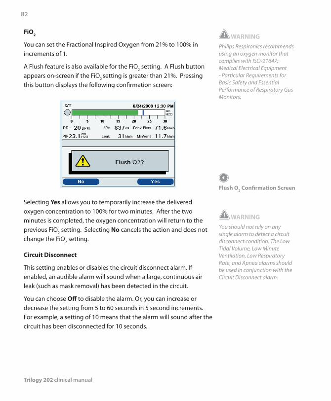
Trilogy 202 clinical manual
82
WARNINGPhilips Respironics recommends using an oxygen monitor that complies with ISO-21647; Medical Electrical Equipment - Particular Requirements for Basic Safety and Essential Performance of Respiratory Gas Monitors.
Flush O2 Confirmation Screen
WARNINGYou should not rely on any single alarm to detect a circuit disconnect condition. The Low Tidal Volume, Low Minute Ventilation, Low Respiratory Rate, and Apnea alarms should be used in conjunction with the Circuit Disconnect alarm.
FiO2
You can set the Fractional Inspired Oxygen from 21% to 100% in increments of 1.
A Flush feature is also available for the FiO2 setting. A Flush button appears on-screen if the FiO2 setting is greater than 21%. Pressing this button displays the following confirmation screen:
Selecting Yes allows you to temporarily increase the delivered oxygen concentration to 100% for two minutes. After the two minutes is completed, the oxygen concentration will return to the previous FiO2 setting. Selecting No cancels the action and does not change the FiO2 setting.
Circuit Disconnect
This setting enables or disables the circuit disconnect alarm. If enabled, an audible alarm will sound when a large, continuous air leak (such as mask removal) has been detected in the circuit.
You can choose Off to disable the alarm. Or, you can increase or decrease the setting from 5 to 60 seconds in 5 second increments. For example, a setting of 10 means that the alarm will sound after the circuit has been disconnected for 10 seconds.
Chapter 5 Viewing and Changing Settings
83
Apnea
This setting enables or disables the apnea alarm. If enabled, an audible alarm will sound when an apnea is detected.
You can choose Off to disable the alarm. Or, you can increase or decrease the setting from 10 to 60 seconds in 5 second increments. For example, a setting of 10 means that the alarm will sound if the time between spontaneous breaths exceeds 10 seconds.
Low Vte
This setting enables or disables the Low Vte alarm. The alarm activates when the estimated exhaled tidal volume is less than or equal to this setting. You can choose Off to disable this alarm, or you can increase or decrease the setting from 40 ml to 2000 ml in 5 ml increments. It cannot be set higher than the High Vte setting.
When AVAPS is On, the alarm activates when the calculated tidal volume is less than 90% of the target tidal volume setting. This alarm can be set to on or off.
High Vte
This setting enables or disables the High Vte alarm. The alarm activates when the estimated exhaled tidal volume is greater than or equal to this setting. You can choose Off to disable this alarm, or you can increase or decrease the setting from 50 ml to 2000 ml in 5 ml increments. It cannot be set lower than the Low Tidal Volume setting, except to be turned off.
Low Vti
This setting enables or disables the Low Vti alarm. The alarm activates when the measured inhaled tidal volume is less than or equal to this setting. You can choose Off to disable this alarm, or you can increase or decrease the setting from 40 ml to 2000 ml in 5 ml increments. It cannot be set higher than the High Vti setting.
Note: The High and Low Vte alarms are available when the Passive or Active Flow Circuit is selected.
Note: The High and Low Vti alarms are only available when the Active PAP Circuit is selected.
Trilogy 202 clinical manual
84
High Vti
This setting enables or disables the High Vti alarm. The alarm activates when the measured inhaled tidal volume is greater than or equal to this setting. You can choose Off to disable this alarm, or you can increase or decrease the setting from 40 ml to 2000 ml in 5 ml increments. It cannot be set lower than the Low Vti setting, except to be turned off.
Low Minute Ventilation
This setting enables or disables the Low Minute Ventilation alarm. The alarm activates when the calculated minute ventilation is less than or equal to this setting. You can choose Off to disable this alarm, or you can increase or decrease the setting from 1 l/min to 99 l/min in 1 l/min increments. It cannot be set higher than the High Minute Ventilation.
High Minute Ventilation
This setting enables or disables the High Minute Ventilation alarm. The alarm activates when the calculated minute ventilation reaches or exceeds this setting. You can choose Off to disable this alarm, or you can increase or decrease the setting from 1 l/min to 99 l/min in 1 l/min increments. It cannot be set lower than the Low Minute Ventilation setting except to be turned off.
Low Respiratory Rate
This setting enables or disables the Low Respiratory Rate alarm. The alarm activates when the measured respiratory rate is less than or equal to this setting. You can choose Off to disable this alarm, or you can increase or decrease the setting from 4 BPM to 80 BPM in 1 BPM increments. It cannot be set higher than the High Respiratory Rate.
High Respiratory Rate
This setting enables or disables the High Respiratory Rate alarm. The alarm activates when the measured respiratory rate reaches or exceeds this setting. You can choose Off to disable this alarm, or you can increase or decrease the setting from 4 BPM to 80 BPM in 1 BPM increments. It cannot be set lower than the Low Respiratory Rate except to be turned off.
Chapter 5 Viewing and Changing Settings
85
Low Inspiratory Pressure
This setting configures the Low Inspiratory Pressure alarm. It is only user-settable in CV, AC, and SIMV modes. It cannot be set lower than PEEP + 2 cmH2O or higher than the High Inspiratory Pressure. For passive circuits, you can increase or decrease the Low Inspiratory Pressure from 6 to 40 cmH2O in increments of 1 cmH2O. For active circuits, you can increase or decrease the setting from 2 to 40 cmH2O in increments of 1 cmH2O. For pressure modes, this alarm is not user-settable.
High Inspiratory Pressure
This setting enables or disables the High Inspiratory Pressure alarm. It is only user-settable in CV, AC, and SIMV modes. The High Inspiratory Pressure cannot be set lower than the Low Inspiratory Pressure. You can increase or decrease the High Inspiratory Pressure from 10 to 80 cmH2O in increments of 1 cmH2O. For pressure modes, this alarm is not user-settable.
Additional Settings Specific to Therapy Modes
The Settings and Alarms menu also contains many additional settings specific to the various therapy modes. The specific settings for each therapy mode are described below.
Continuous Positive Airway Pressure (CPAP) Mode
In addition to the general settings described in the previous section of this manual, you can also set the following settings in CPAP mode.
1. CPAP
You can increase or decrease the CPAP pressure setting from 4 to 20 cmH2O in increments of 1.
Note: If the CPAP pressure is set to 4 (the minimum setting), the Ramp Length setting will be unavailable.
Trilogy 202 clinical manual
86
Note: Trigger Type is not available when an Active PAP or Active Flow circuit is selected. Flow trigger is the triggering method used for Active PAP and Active Flow circuits.
Note: Flow Trigger with leak compensation is only available if the Active Flow circuit is selected.
Note: Enabling Leak Compensation when using the Active Flow Circuit configuration only affects triggering and does not affect tidal volume delivery or Vte measurement.
Note: Auto-Trak is only available if the Passive Circuit is selected.
2. Trigger Type
The device can be set to trigger breaths based on automatic flow thresholds or specific flow settings. You can select Auto-Trak or Flow Trigger as the Trigger Type. When Auto-Trak is selected, the Auto-Trak trigger initiates based on automatic flow thresholds. When Trigger Type is set to Flow Trigger, Flow Trigger Sensitivity Leak Compensation, and Flow Cycle Sensitivity become active, and the trigger initiates based on the Flow Trigger Sensitivity setting.
3. Flow Trigger Sensitivity
If you set the Trigger Type to Flow Trigger, the Flow Trigger Sensitivity setting displays. You can increase or decrease the setting from 1 to 9 l/min in 1 l/min increments.
The flow trigger initiates when the patient’s inspiratory effort creates a flow equal to or greater than the flow sensitivity setting.
4. Leak Compensation
If you are using an Active Flow circuit, you can turn Leak Compensation On or Off.
5. Flow Cycle Sensitivity
If you set the Trigger Type to Flow Trigger, the Flow Cycle Sensitivity setting displays. You can increase or decrease the setting from 10 to 90 percent (%) in 1% increments.
As flow begins to decrease during inspiration, if the patient flow is less that the flow cycle set point, the device will cycle to expiration. For example: if the flow cycle is set to 25%, when the flow has decreased by 25% of the peak flow, the device will cycle to the EPAP/PEEP level.
6. Ramp Length
The Ramp Length allows you to set the ramp time. You can disable Ramp by selecting Off, or you can increase or decrease the Ramp Length setting from 5 to 45 minutes in 5-minute increments.
Chapter 5 Viewing and Changing Settings
87
7. Ramp Start Pressure
You can increase or decrease the ramp start pressure in increments of 1 from 4 cmH2O to the CPAP pressure setting. The patient also has access to this setting, unless the ramp length is set to Off.
8. Flex
You can enable or disable the Flex setting. Off disables the setting. To enable the setting, set Flex to 1, 2, or 3. The Flex feature is not available when using an active circuit type.
Spontaneous (S) Mode
The following settings, described in the CPAP mode section of this chapter, also are available in S mode:
Flex •Trigger Type •Flow Trigger Sensitivity •Flow Cycle Sensitivity •Ramp Length •Ramp Start Pressure •
In addition to those settings, the settings below are also available in S/T mode.
1. AVAPS
AVAPS is only available if Flex is not enabled.
You can disable AVAPS by selecting Off, or you can enable AVAPS by selecting On. If you select Off, the IPAP setting displays. If you select On, the IPAP Max Pressure and IPAP Min Pressure display.
Note: The Ramp Start Pressure setting will not display if the Ramp Length is set to Off or if the CPAP pressure is set to 4 cmH2O.
Note: Ramp Start Pressure is less than or equal to CPAP - 1 cmH2O in CPAP mode.
Note: In CPAP mode, Flex is only available when CPAP is greater than 4 cmH2O.
Note: In S mode, Flex is only available when EPAP is greater than or equal to 4 cmH2O and IPAP is less than or equal to 25 cmH2O.
Note: Flex is only available when Auto-Trak is enabled.
Note: Ramp is not available in the Passive Circuit when IPAP = EPAP = 4 cmH2O or when IPAP Min = EPAP = 4 cmH2O.
Note: Ramp Start Pressure is less than or equal to EPAP - 1 cmH2O in S, S/T, T, and PC modes.
Note: Ramp Start Pressure is greater than or equal to 0 cmH2O when the circuit type is Active PAP or Active Flow in S, S/T, T, and PC modes.
Note: Ramp Start Pressure is greater than or equal to 4 cmH2O when the circuit type is Passive in S, S/T, T, and PC modes.
Note: AVAPS is only available if the Passive Circuit is selected.
Trilogy 202 clinical manual
88
Note: IPAP, IPAP Max, or IPAP Min cannot be set to more than 30 cmH2O above EPAP.
Note: EPAP cannot be set to more than 30 cmH2O below IPAP, IPAP Max, or IPAP Min.
Note: In CV, AC, and SIMV modes, the tidal volume setting is limited by the Inspiratory Time, to maintain the system’s minimum and maximum peak flows.
2. IPAP
The IPAP setting displays if AVAPS is Off. You can increase or decrease the Inspiratory Positive Airway Pressure (IPAP) from 4 to 50 cmH2O in increments of 1. IPAP is limited to a maximum of 25 cmH2O when Flex is enabled. You cannot set the IPAP setting lower than the EPAP setting.
3. IPAP Max Pressure
The IPAP Max Pressure setting displays if AVAPS is enabled. You can increase or decrease the setting from 4 to 50 cmH2O in increments of 1. The IPAP Max Pressure must be equal to or greater than the IPAP Min value.
4. IPAP Min Pressure
The IPAP Min Pressure setting displays if AVAPS is enabled. You can increase or decrease the setting from 4 to 50 cmH2O in increments of 1. The IPAP Min Pressure must be equal to or greater than the EPAP value, and it must be less than or equal to the IPAP Max Pressure.
5. EPAP
You can increase or decrease the Expiratory Positive Airway Pressure (EPAP) from 4 to 25 cmH2O in increments of 1. For active circuits, EPAP can be set to zero.
When AVAPS is disabled, the EPAP setting must be less than or equal to the IPAP setting. When AVAPS is enabled, the EPAP pressure must be less than or equal to the IPAP Min Pressure.
6. Tidal Volume
The Tidal Volume setting displays if AVAPS is enabled. You can increase or decrease the setting from 50 to 2000 ml in 5 ml increments. Use this setting to establish the target volume of gas which the ventilator will produce and deliver during each Spontaneous breath.
Chapter 5 Viewing and Changing Settings
89
7. Rise Time
You can adjust the rise time to find the most comfortable setting for the patient. Increase or decrease the setting from 1 to 6 until you find the right setting. The rise time levels from 1 to 6 progressively reflect slowed response of the pressure increase that will take place at the beginning of inspiration.
8. Apnea Rate
If the Apnea alarm is enabled, you can set the Apnea Rate from 4 to 60 BPM in 1 BPM increments. In S mode, the Apnea Rate is greater than or equal to 1:2 I:E ratio.
Spontaneous/Timed (S/T) Mode
All of the settings described in the S Mode section are also available in S/T mode, except for the Flex setting. In addition to those settings, the settings below are also available in S/T mode.
1. Breath Rate
In AC mode, you can increase or decrease the Breath Rate setting from 0 to 60 BPM, while in all other modes, you can increase or decrease the setting from 1 to 60 BPM in 1 BPM increments. Use the Breath Rate setting to establish the minimum rate of mandatory breaths that the ventilator will deliver per minute.
2. Inspiratory Time
You can adjust the Inspiratory Time setting from 0.3 to 5.0 seconds in 0.1 second increments. Inspiratory Time is the duration for the inspiratory phase of a mandatory breath.
Timed (T) Mode
All of the settings available in S/T mode are available in T mode, except for the Trigger Type setting. Please refer to the descriptions in the S and S/T Mode sections of this chapter for detailed information on the T mode settings.
Note: The Rise Time setting only displays if Flex is disabled. If Flex is enabled, the device will use a rise time of 3.
Note: In S/T, T, PC, PC-SIMV, SIMV, CV, and AC modes, the Apnea Rate is greater than or equal to the Breath Rate and is limited by the current Inspiratory Time setting to maintain a minimum 1:1 I:E ratio.
Note: In volume modes, the Breath Rate range is limited by the current Inspiratory Time setting to maintain a minimum 1:1 I:E ratio.
Note: In pressure modes, the inspiratory time range is limited by the current Breath Rate setting to maintain a minimum 1:1 I:E ratio.
Note: In volume modes, the inspiratory time range is limited by the current Tidal Volume and Breath Rate settings to maintain a minimum 1:1 I:E ratio and the system’s minimum and maximum peak flow.
Trilogy 202 clinical manual
90
Note: In PC-SIMV mode, you cannot set up Pressure Support for Mandatory and Assist breaths (Pressure - PEEP) greater than 30 cmH2O.
Note: The Pressure Support and PEEP settings together cannot exceed 50 cmH2O.
Pressure Control (PC) Mode
All of the settings available in S/T mode are available in PC mode, except for the Flow Cycle Sensitivity setting (when Flow Trigger is enabled). Please refer to the descriptions in the S and S/T Mode sections of this chapter for detailed information on the PC mode settings.
Pressure Control Synchronized Intermittent Mandatory Ventilation
(PC-SIMV) Mode
The following settings, described in the S and S/T mode sections of this chapter, also are available in PC-SIMV mode:
Breath Rate •Inspiratory Time •Trigger Type •Flow Trigger Sensitivity (if Trigger Type is set to Flow •Trigger)
Flow Cycle Sensitivity (if Trigger Type is set to Flow •Trigger)
Rise Time •In addition to these, the following settings are also available in PC-SIMV mode.
1. Pressure
You can increase or decrease the Pressure setting from 4 to 50 cmH2O in increments of 1. This is the pressure the ventilator will deliver during the inspiratory phase of a mandatory or assist breath.
2. Pressure Support
You can increase or decrease the Pressure Support setting from 0 to 30 cmH2O in increments of 1. This is the pressure support the ventilator will deliver during the inspiratory phase of a Spontaneous breath.
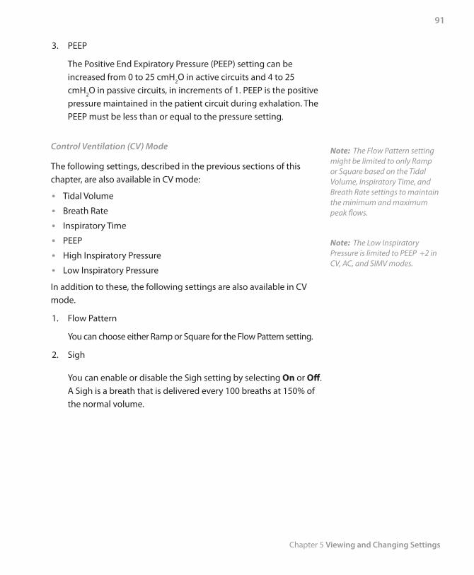
Chapter 5 Viewing and Changing Settings
91
3. PEEP
The Positive End Expiratory Pressure (PEEP) setting can be increased from 0 to 25 cmH2O in active circuits and 4 to 25 cmH2O in passive circuits, in increments of 1. PEEP is the positive pressure maintained in the patient circuit during exhalation. The PEEP must be less than or equal to the pressure setting.
Control Ventilation (CV) Mode
The following settings, described in the previous sections of this chapter, are also available in CV mode:
Tidal Volume •Breath Rate •Inspiratory Time •PEEP •High Inspiratory Pressure •Low Inspiratory Pressure •
In addition to these, the following settings are also available in CV mode.
1. Flow Pattern
You can choose either Ramp or Square for the Flow Pattern setting.
2. Sigh
You can enable or disable the Sigh setting by selecting On or Off. A Sigh is a breath that is delivered every 100 breaths at 150% of the normal volume.
Note: The Flow Pattern setting might be limited to only Ramp or Square based on the Tidal Volume, Inspiratory Time, and Breath Rate settings to maintain the minimum and maximum peak flows.
Note: The Low Inspiratory Pressure is limited to PEEP +2 in CV, AC, and SIMV modes.
Trilogy 202 clinical manual
92
Assist Control (AC) Mode
The AC mode contains the following settings described in the S, S/T, PC-SIMV, and CV mode sections in this chapter. Please refer to the descriptions in those sections for detailed information.
Tidal Volume •Breath Rate •Inspiratory Time •Flow Pattern •PEEP •Trigger Type •Flow Trigger Sensitivity •Sigh •High Inspiratory Pressure •Low Inspiratory Pressure •
Synchronized Intermittent Mandatory Ventilation (SIMV) Mode
The SIMV mode contains the following settings described in the S, S/T, PC-SIMV, and CV mode sections in this chapter. Please refer to the descriptions in those sections for detailed information.
Tidal Volume •Breath Rate •Inspiratory Time •Pressure Support •Flow Pattern •PEEP •Trigger Type •Sigh •Rise Time •High Inspiratory Pressure •Low Inspiratory Pressure •
Note: Flow Cycle Sensitivity is not available in AC mode.
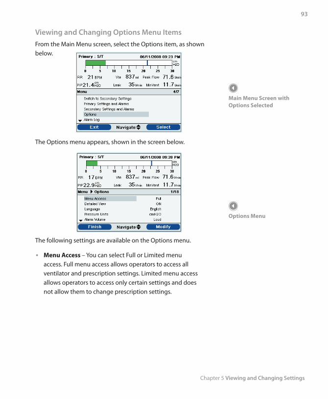
Chapter 5 Viewing and Changing Settings
93
Viewing and Changing Options Menu ItemsFrom the Main Menu screen, select the Options item, as shown below.
The Options menu appears, shown in the screen below.
The following settings are available on the Options menu.
• Menu Access – You can select Full or Limited menu access. Full menu access allows operators to access all ventilator and prescription settings. Limited menu access allows operators to access only certain settings and does not allow them to change prescription settings.
Main Menu Screen with Options Selected
Options Menu
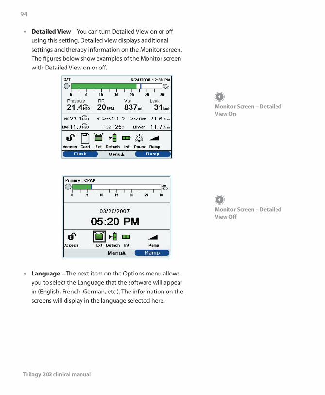
Trilogy 202 clinical manual
94
• Detailed View – You can turn Detailed View on or off using this setting. Detailed view displays additional settings and therapy information on the Monitor screen. The figures below show examples of the Monitor screen with Detailed View on or off.
• Language – The next item on the Options menu allows you to select the Language that the software will appear in (English, French, German, etc.). The information on the screens will display in the language selected here.
Monitor Screen – Detailed View On
Monitor Screen – Detailed View Off
Chapter 5 Viewing and Changing Settings
95
• Pressure Units – The next item allows you to select the pressure units that will display on the screens. You can choose either:
- cm H2O
- hPa
- mBar
All pressure units on the screens will display in the unit of measure selected here.
• Alarm Volume – You can adjust the volume of the device alarms using this setting. Select either Loud or Soft as the alarm volume options.
• Keypad Lock – You can enable or disable the Keypad Lock feature, which is described in detail earlier in this chapter. Enabling the Keypad Lock feature can prevent someone from accidentally pressing a button and changing any of the settings. Select On to enable the feature or Off to disable it.
• Keypad Backlight – The next item you can set is the Keypad Backlight. You can turn the backlight On or Off using this setting. Whenever you press the button to begin therapy, the keypad backlight temporarily lights up. Once therapy is being provided, the keypad will be lit according to this Keypad Backlight setting. If the setting is On, the backlight remains on while therapy is provided. If the setting is Off, the backlight remains off while therapy is provided.
• LCD Brightness – The LCD display is lit by a backlight. The backlight turns on when the initial Startup screen displays. You can adjust the brightness of the LCD backlight from 1 – 10, with 1 being the dimmest setting and 10 being the brightest.
WARNING
Make sure the alarm volume is set loud enough to be heard by the caregiver. Consider the use of a remote alarm.
Trilogy 202 clinical manual
96
• Screen Saver – You can change the screen saver to reduce power consumption or dim the screen in a dark room. You can choose the following settings:
- Off: No screen saver displays and the LCD backlight remains lit at your brightness setting.
- Breath: The display appears as a black screen, with only the patient breath indicator and manometer visible.
- Black: The display’s backlight is turned off and the display is black with no information visible.
- Dim: The display’s backlight is decreased, so that the display is still visible but not as bright.
If enabled, the screen saver will display after 5 minutes of no keypad activity. Pressing any button on the device will exit the screen saver. And, any alarm or informational message will also exit the screen saver.
• Date Format – You can choose either mm/dd/yyyy or dd/mm/yyyy as the date format that will display on the device screens.
• Time Format – You can choose to display either an AM/PM time format or 24 Hour time format (for example, 2:49 PM or 14:49).
Month • – The month defaults to the current month. The adjustable range is from 1 (January) – 12 (December).
Day • – The day defaults to the current day. The adjustable range is from 1 – 31. The maximum value is based on the selected month.
Year • – The year defaults to the current year. The adjustable range is from 2000 – 2099.
Hour • – The hour defaults to the current hour. The adjustable range is from 12 AM – 12 PM or 0-23, depending on the selected Time Format.
Note: Setting the screen saver to Black allows the device to run for a longer period of time on battery power.
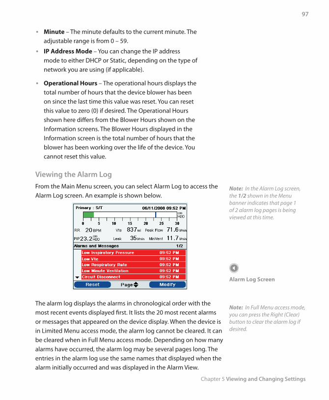
Chapter 5 Viewing and Changing Settings
97
Minute • – The minute defaults to the current minute. The adjustable range is from 0 – 59.
• IP Address Mode – You can change the IP address mode to either DHCP or Static, depending on the type of network you are using (if applicable).
• Operational Hours – The operational hours displays the total number of hours that the device blower has been on since the last time this value was reset. You can reset this value to zero (0) if desired. The Operational Hours shown here differs from the Blower Hours shown on the Information screens. The Blower Hours displayed in the Information screen is the total number of hours that the blower has been working over the life of the device. You cannot reset this value.
Viewing the Alarm LogFrom the Main Menu screen, you can select Alarm Log to access the Alarm Log screen. An example is shown below.
The alarm log displays the alarms in chronological order with the most recent events displayed first. It lists the 20 most recent alarms or messages that appeared on the device display. When the device is in Limited Menu access mode, the alarm log cannot be cleared. It can be cleared when in Full Menu access mode. Depending on how many alarms have occurred, the alarm log may be several pages long. The entries in the alarm log use the same names that displayed when the alarm initially occurred and was displayed in the Alarm View.
Note: In the Alarm Log screen, the 1/2 shown in the Menu banner indicates that page 1 of 2 alarm log pages is being viewed at this time.
Alarm Log Screen
Note: In Full Menu access mode, you can press the Right (Clear) button to clear the alarm log if desired.
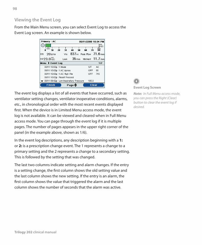
Trilogy 202 clinical manual
98
Viewing the Event LogFrom the Main Menu screen, you can select Event Log to access the Event Log screen. An example is shown below.
The event log displays a list of all events that have occurred, such as ventilator setting changes, ventilator inoperative conditions, alarms, etc., in chronological order with the most recent events displayed first. When the device is in Limited Menu access mode, the event log is not available. It can be viewed and cleared when in Full Menu access mode. You can page through the event log if it is multiple pages. The number of pages appears in the upper right corner of the panel (in the example above, shown as 1/6).
In the event log descriptions, any description beginning with a 1: or 2: is a prescription change event. The 1 represents a change to a primary setting and the 2 represents a change to a secondary setting. This is followed by the setting that was changed.
The last two columns indicate setting and alarm changes. If the entry is a setting change, the first column shows the old setting value and the last column shows the new setting. If the entry is an alarm, the first column shows the value that triggered the alarm and the last column shows the number of seconds that the alarm was active.
Event Log Screen
Note: In Full Menu access mode, you can press the Right (Clear) button to clear the event log if desired.
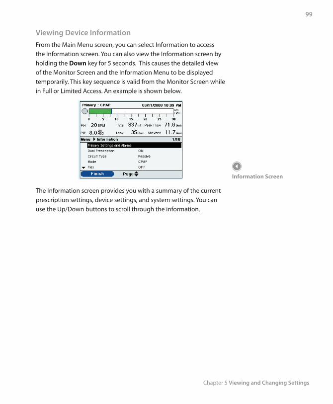
Chapter 5 Viewing and Changing Settings
99
Viewing Device InformationFrom the Main Menu screen, you can select Information to access the Information screen. You can also view the Information screen by holding the Down key for 5 seconds. This causes the detailed view of the Monitor Screen and the Information Menu to be displayed temporarily. This key sequence is valid from the Monitor Screen while in Full or Limited Access. An example is shown below.
The Information screen provides you with a summary of the current prescription settings, device settings, and system settings. You can use the Up/Down buttons to scroll through the information.
Information Screen
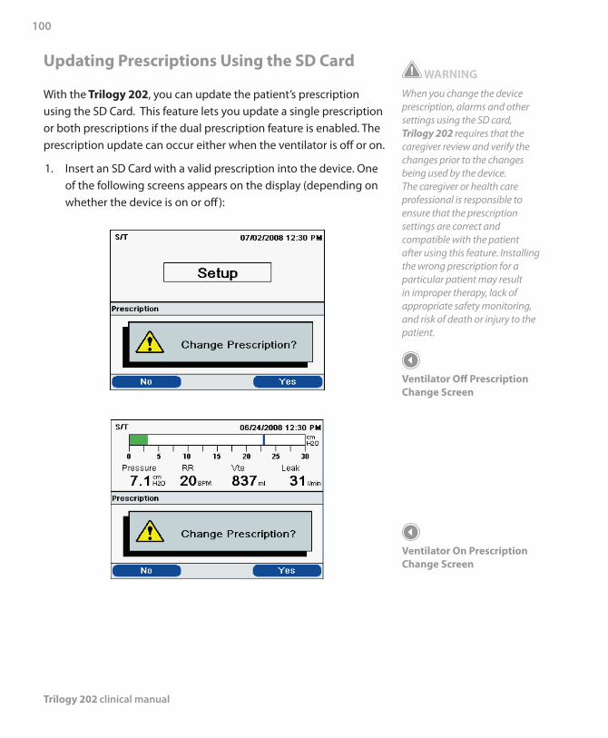
Trilogy 202 clinical manual
100
Updating Prescriptions Using the SD Card
With the Trilogy 202, you can update the patient’s prescription using the SD Card. This feature lets you update a single prescription or both prescriptions if the dual prescription feature is enabled. The prescription update can occur either when the ventilator is off or on.
1. Insert an SD Card with a valid prescription into the device. One of the following screens appears on the display (depending on whether the device is on or off):
WARNING
When you change the device prescription, alarms and other settings using the SD card, Trilogy 202 requires that the caregiver review and verify the changes prior to the changes being used by the device. The caregiver or health care professional is responsible to ensure that the prescription settings are correct and compatible with the patient after using this feature. Installing the wrong prescription for a particular patient may result in improper therapy, lack of appropriate safety monitoring, and risk of death or injury to the patient.
Ventilator Off Prescription Change Screen
Ventilator On Prescription Change Screen
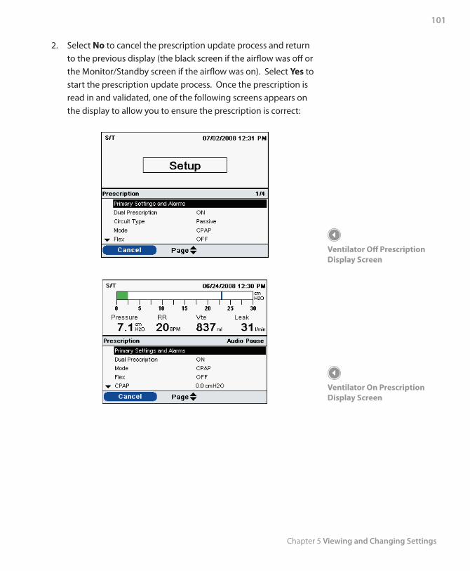
Chapter 5 Viewing and Changing Settings
101
2. Select No to cancel the prescription update process and return to the previous display (the black screen if the airflow was off or the Monitor/Standby screen if the airflow was on). Select Yes to start the prescription update process. Once the prescription is read in and validated, one of the following screens appears on the display to allow you to ensure the prescription is correct:
Ventilator Off Prescription Display Screen
Ventilator On Prescription Display Screen
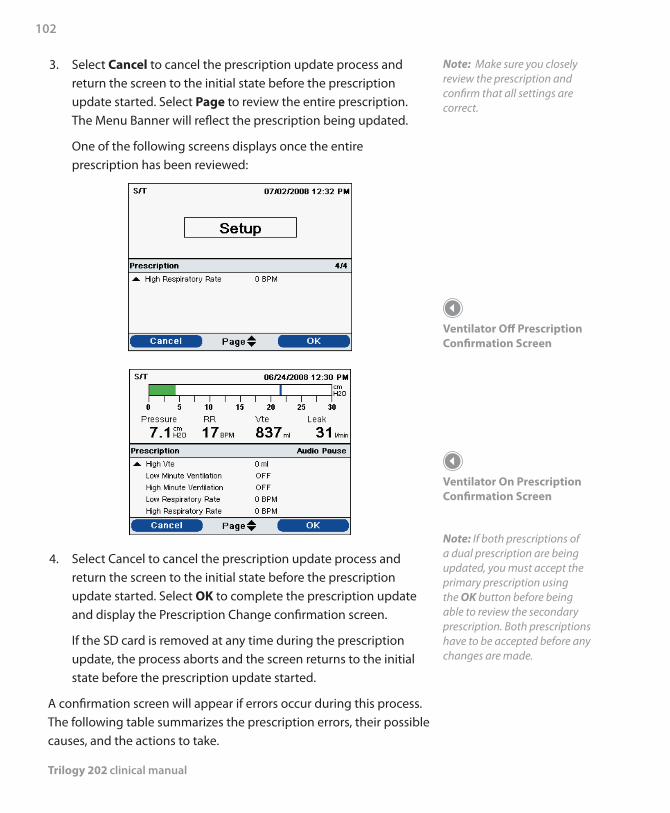
Trilogy 202 clinical manual
102
3. Select Cancel to cancel the prescription update process and return the screen to the initial state before the prescription update started. Select Page to review the entire prescription. The Menu Banner will reflect the prescription being updated.
One of the following screens displays once the entire prescription has been reviewed:
4. Select Cancel to cancel the prescription update process and return the screen to the initial state before the prescription update started. Select OK to complete the prescription update and display the Prescription Change confirmation screen.
If the SD card is removed at any time during the prescription update, the process aborts and the screen returns to the initial state before the prescription update started.
A confirmation screen will appear if errors occur during this process. The following table summarizes the prescription errors, their possible causes, and the actions to take.
Note: Make sure you closely review the prescription and confirm that all settings are correct.
Ventilator Off Prescription Confirmation Screen
Ventilator On Prescription Confirmation Screen
Note: If both prescriptions of a dual prescription are being updated, you must accept the primary prescription using the OK button before being able to review the secondary prescription. Both prescriptions have to be accepted before any changes are made.
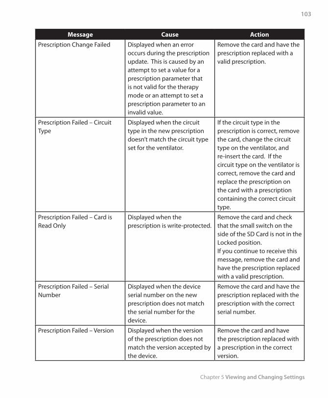
Chapter 5 Viewing and Changing Settings
103
Message Cause Action
Prescription Change Failed Displayed when an error occurs during the prescription update. This is caused by an attempt to set a value for a prescription parameter that is not valid for the therapy mode or an attempt to set a prescription parameter to an invalid value.
Remove the card and have the prescription replaced with a valid prescription.
Prescription Failed – Circuit Type
Displayed when the circuit type in the new prescription doesn’t match the circuit type set for the ventilator.
If the circuit type in the prescription is correct, remove the card, change the circuit type on the ventilator, and re-insert the card. If the circuit type on the ventilator is correct, remove the card and replace the prescription on the card with a prescription containing the correct circuit type.
Prescription Failed – Card is Read Only
Displayed when the prescription is write-protected.
Remove the card and check that the small switch on the side of the SD Card is not in the Locked position.If you continue to receive this message, remove the card and have the prescription replaced with a valid prescription.
Prescription Failed – Serial Number
Displayed when the device serial number on the new prescription does not match the serial number for the device.
Remove the card and have the prescription replaced with the prescription with the correct serial number.
Prescription Failed – Version Displayed when the version of the prescription does not match the version accepted by the device.
Remove the card and have the prescription replaced with a prescription in the correct version.
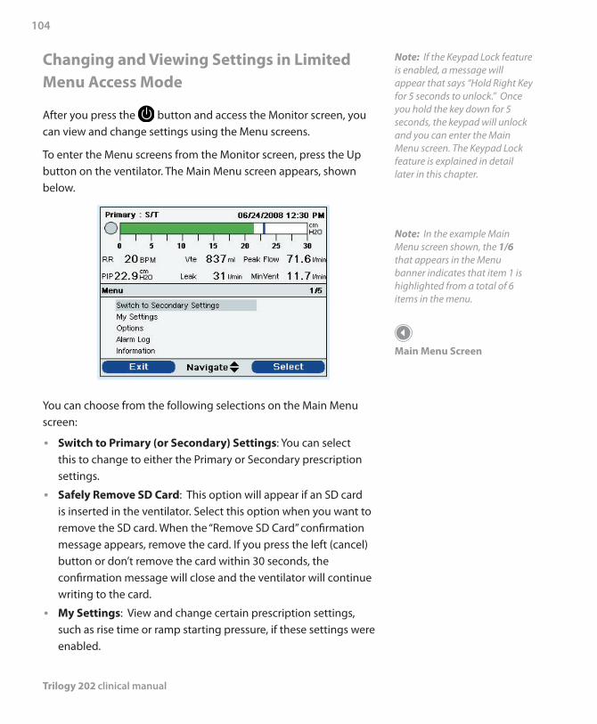
Trilogy 202 clinical manual
104
Changing and Viewing Settings in Limited Menu Access Mode
After you press the button and access the Monitor screen, you can view and change settings using the Menu screens.
To enter the Menu screens from the Monitor screen, press the Up button on the ventilator. The Main Menu screen appears, shown below.
You can choose from the following selections on the Main Menu screen:
Switch to Primary (or Secondary) Settings • : You can select this to change to either the Primary or Secondary prescription settings.
Safely Remove SD Card • : This option will appear if an SD card is inserted in the ventilator. Select this option when you want to remove the SD card. When the “Remove SD Card” confirmation message appears, remove the card. If you press the left (cancel) button or don’t remove the card within 30 seconds, the confirmation message will close and the ventilator will continue writing to the card.
My Settings • : View and change certain prescription settings, such as rise time or ramp starting pressure, if these settings were enabled.
Note: If the Keypad Lock feature is enabled, a message will appear that says “Hold Right Key for 5 seconds to unlock.” Once you hold the key down for 5 seconds, the keypad will unlock and you can enter the Main Menu screen. The Keypad Lock feature is explained in detail later in this chapter.
Note: In the example Main Menu screen shown, the 1/6 that appears in the Menu banner indicates that item 1 is highlighted from a total of 6 items in the menu.
Main Menu Screen
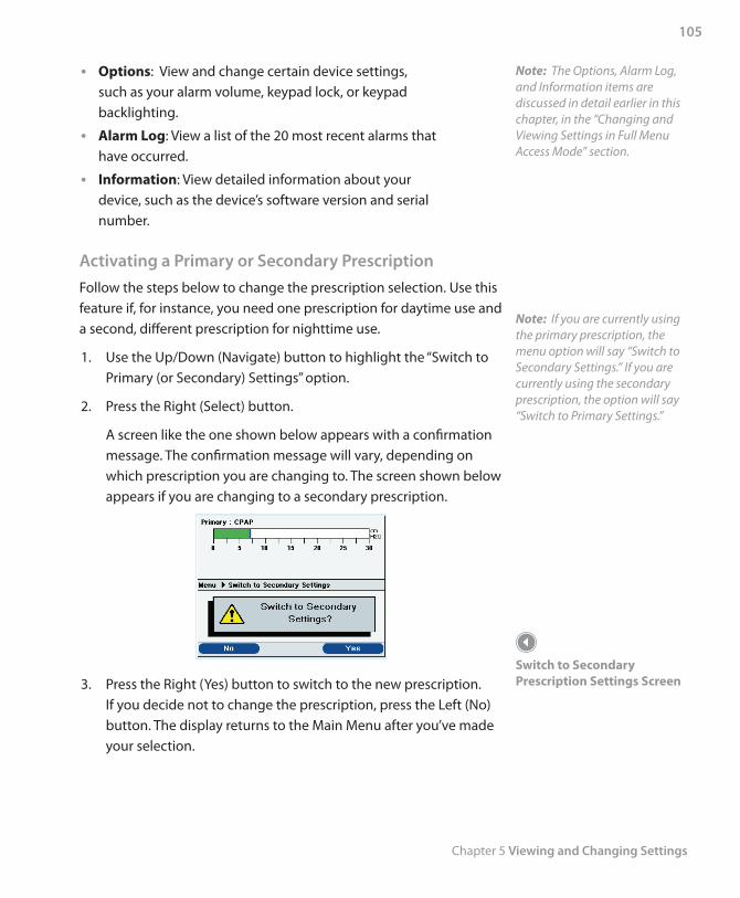
Chapter 5 Viewing and Changing Settings
105
Options • : View and change certain device settings, such as your alarm volume, keypad lock, or keypad backlighting.
Alarm Log • : View a list of the 20 most recent alarms that have occurred.
Information • : View detailed information about your device, such as the device’s software version and serial number.
Activating a Primary or Secondary PrescriptionFollow the steps below to change the prescription selection. Use this feature if, for instance, you need one prescription for daytime use and a second, different prescription for nighttime use.
1. Use the Up/Down (Navigate) button to highlight the “Switch to Primary (or Secondary) Settings” option.
2. Press the Right (Select) button.
A screen like the one shown below appears with a confirmation message. The confirmation message will vary, depending on which prescription you are changing to. The screen shown below appears if you are changing to a secondary prescription.
3. Press the Right (Yes) button to switch to the new prescription. If you decide not to change the prescription, press the Left (No) button. The display returns to the Main Menu after you’ve made your selection.
Note: The Options, Alarm Log, and Information items are discussed in detail earlier in this chapter, in the “Changing and Viewing Settings in Full Menu Access Mode” section.
Note: If you are currently using the primary prescription, the menu option will say “Switch to Secondary Settings.” If you are currently using the secondary prescription, the option will say “Switch to Primary Settings.”
Switch to Secondary Prescription Settings Screen
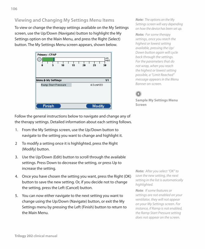
Trilogy 202 clinical manual
106
Viewing and Changing My Settings Menu ItemsTo view or change the therapy settings available on the My Settings screen, use the Up/Down (Navigate) button to highlight the My Settings option on the Main Menu, and press the Right (Select) button. The My Settings Menu screen appears, shown below.
Follow the general instructions below to navigate and change any of the therapy settings. Detailed information about each setting follows.
1. From the My Settings screen, use the Up/Down button to navigate to the setting you want to change and highlight it.
2 To modify a setting once it is highlighted, press the Right (Modify) button.
3. Use the Up/Down (Edit) button to scroll through the available settings. Press Down to decrease the setting, or press Up to increase the setting.
4. Once you have chosen the setting you want, press the Right (OK) button to save the new setting. Or, if you decide not to change the setting, press the Left (Cancel) button.
5. You can now either navigate to the next setting you want to change using the Up/Down (Navigate) button, or exit the My Settings menu by pressing the Left (Finish) button to return to the Main Menu.
Note: The options on the My Settings screen will vary depending on how the device has been set up.
Note: For some therapy settings, once you reach the highest or lowest setting available, pressing the Up/ Down button again will cycle back through the settings. For the parameters that do not wrap, when you reach the highest or lowest setting possible, a “Limit Reached” message appears in the Menu Banner on-screen.
Sample My Settings Menu Screen
Note: After you select “OK” to save the new setting, the next setting in the list is automatically highlighted.
Note: If some features or settings are not enabled on your ventilator, they will not appear on your My Settings screen. For instance, if Ramp is not enabled, the Ramp Start Pressure setting does not appear on the screen.
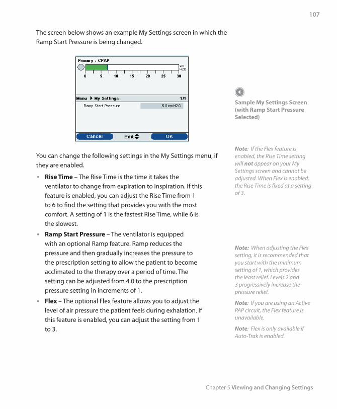
Chapter 5 Viewing and Changing Settings
107
The screen below shows an example My Settings screen in which the Ramp Start Pressure is being changed.
You can change the following settings in the My Settings menu, if they are enabled.
• Rise Time – The Rise Time is the time it takes the ventilator to change from expiration to inspiration. If this feature is enabled, you can adjust the Rise Time from 1 to 6 to find the setting that provides you with the most comfort. A setting of 1 is the fastest Rise Time, while 6 is the slowest.
• Ramp Start Pressure – The ventilator is equipped with an optional Ramp feature. Ramp reduces the pressure and then gradually increases the pressure to the prescription setting to allow the patient to become acclimated to the therapy over a period of time. The setting can be adjusted from 4.0 to the prescription pressure setting in increments of 1.
• Flex – The optional Flex feature allows you to adjust the level of air pressure the patient feels during exhalation. If this feature is enabled, you can adjust the setting from 1 to 3.
Sample My Settings Screen (with Ramp Start Pressure Selected)
Note: If the Flex feature is enabled, the Rise Time setting will not appear on your My Settings screen and cannot be adjusted. When Flex is enabled, the Rise Time is fixed at a setting of 3.
Note: When adjusting the Flex setting, it is recommended that you start with the minimum setting of 1, which provides the least relief. Levels 2 and 3 progressively increase the pressure relief.
Note: If you are using an Active PAP circuit, the Flex feature is unavailable.
Note: Flex is only available if Auto-Trak is enabled.
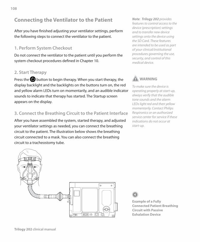
Trilogy 202 clinical manual
108
Connecting the Ventilator to the Patient
After you have finished adjusting your ventilator settings, perform the following steps to connect the ventilator to the patient.
1. Perform System CheckoutDo not connect the ventilator to the patient until you perform the system checkout procedures defined in Chapter 10.
2. Start TherapyPress the button to begin therapy. When you start therapy, the display backlight and the backlights on the buttons turn on, the red and yellow alarm LEDs turn on momentarily, and an audible indicator sounds to indicate that therapy has started. The Startup screen appears on the display.
3. Connect the Breathing Circuit to the Patient InterfaceAfter you have assembled the system, started therapy, and adjusted your ventilator settings as needed, you can connect the breathing circuit to the patient. The illustration below shows the breathing circuit connected to a mask. You can also connect the breathing circuit to a tracheostomy tube.
Note: Trilogy 202 provides features to control access to the device (prescription) settings and to transfer new device settings onto the device using the SD Card. These features are intended to be used as part of your clinical/institutional procedures governing the use, security, and control of this medical device.
WARNING
To make sure the device is operating properly at start-up, always verify that the audible tone sounds and the alarm LEDs light red and then yellow momentarily. Contact Philips Respironics or an authorized service center for service if these indications do not occur at start-up.
Example of a Fully Connected Patient Breathing Circuit with Passive Exhalation Device
Chapter 6 Ventilator Alarms
109
This chapter describes the ventilator alarms and what you should do if an alarm occurs.
There are three types of alarms:
High Priority – Require immediate response by the •operator
Medium Priority – Require prompt response by the •operator
Low Priority – Require operator awareness. These alarms •alert you to a change in the ventilator status.
Additionally, the ventilator also displays informational messages and confirmation alerts that notify you of conditions that need attention but do not qualify as alarm conditions.
Note: If multiple alarms occur at the same time, all alarms are processed and displayed, but the alarms are ordered first by priority and then by occurrence, with the newest, highest priority alarms at the top of the list. The alarm precedence is in the following order: high priority, medium priority, low priority, and informational messages.
Note: Not all alarms are available in every therapy mode; some alarms are mode-dependent.
Trilogy 202clinical manual
6. Ventilator Alarms
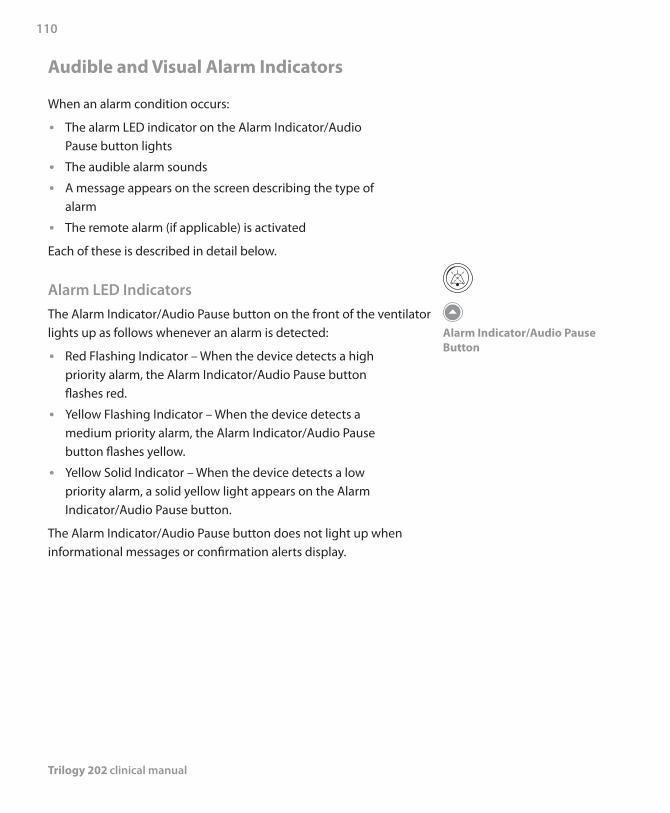
Trilogy 202 clinical manual
110
Audible and Visual Alarm Indicators
When an alarm condition occurs:
The alarm LED indicator on the Alarm Indicator/Audio •Pause button lights
The audible alarm sounds •A message appears on the screen describing the type of •alarm
The remote alarm (if applicable) is activated •Each of these is described in detail below.
Alarm LED IndicatorsThe Alarm Indicator/Audio Pause button on the front of the ventilator lights up as follows whenever an alarm is detected:
Red Flashing Indicator – When the device detects a high •priority alarm, the Alarm Indicator/Audio Pause button flashes red.
Yellow Flashing Indicator – When the device detects a •medium priority alarm, the Alarm Indicator/Audio Pause button flashes yellow.
Yellow Solid Indicator – When the device detects a low •priority alarm, a solid yellow light appears on the Alarm Indicator/Audio Pause button.
The Alarm Indicator/Audio Pause button does not light up when informational messages or confirmation alerts display.
Alarm Indicator/Audio Pause Button
Chapter 6 Ventilator Alarms
111
Note: For the alarm indicators noted throughout this manual, each “dot” represents an audible beep.
Audible IndicatorsAn audible indicator sounds whenever a power failure or a high, medium, or low priority alarm is detected. Additionally, an audible indicator sounds for informational messages and to confirm that certain actions have occurred (for example, when an SD card is inserted or removed from the device).
Ventilator Inoperative Audible Indicator – When a •ventilator inoperative alarm occurs, a continuous audible alarm sounds. The alarm descriptions later in this chapter display this indicator as:
Power Failure Audible Indicator – When a power failure •occurs, a series of beeps sounds in a 1 beep pattern, repeating one second on, then one second off. The alarm descriptions later in this chapter display this indicator as: • •
High Priority Audible Indicator – When a high priority •alarm is detected, a series of beeps sound in the following pattern, which is repeated twice: 3 beeps, a pause, and then 2 more beeps. This indicator continues until the cause of the alarm is corrected or the audible alarm is paused. The alarm descriptions later in this chapter display this indicator as: • • • • • • • • • •Medium Priority Audible Indicator – When a medium •priority alarm is detected, a series of beeps sound in a 3-beep pattern. This pattern repeats until the cause of the alarm is corrected or the audible alarm is paused. The alarm descriptions later in this chapter display this indicator as: • • •Low Priority Audible Indicator – When a low priority •alarm is detected, a series of beeps sound in a 2-beep pattern. This pattern repeats until the cause of the alarm is corrected or the audible alarm is paused. The alarm descriptions later in this chapter display this indicator as: • •
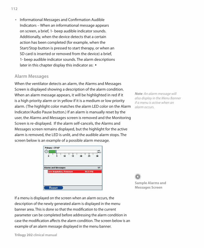
Trilogy 202 clinical manual
112
Informational Messages and Confirmation Audible •Indicators – When an informational message appears on screen, a brief, 1- beep audible indicator sounds. Additionally, when the device detects that a certain action has been completed (for example, when the Start/Stop button is pressed to start therapy, or when an SD card is inserted or removed from the device) a brief, 1- beep audible indicator sounds. The alarm descriptions later in this chapter display this indicator as: •
Alarm MessagesWhen the ventilator detects an alarm, the Alarms and Messages Screen is displayed showing a description of the alarm condition. When an alarm message appears, it will be highlighted in red if it is a high priority alarm or in yellow if it is a medium or low priority alarm. (The highlight color matches the alarm LED color on the Alarm Indicator/Audio Pause button.) If an alarm is manually reset by the user, the Alarms and Messages screen is removed and the Monitoring Screen is re-displayed. If the alarm self-cancels, the Alarms and Messages screen remains displayed, but the highlight for the active alarm is removed, the LED is unlit, and the audible alarm stops. The screen below is an example of a possible alarm message.
If a menu is displayed on the screen when an alarm occurs, the description of the newly generated alarm is displayed in the menu banner area. This is done so that the modification to the current parameter can be completed before addressing the alarm condition in case the modification affects the alarm condition. The screen below is an example of an alarm message displayed in the menu banner.
Note: An alarm message will also display in the Menu Banner if a menu is active when an alarm occurs.
Sample Alarms and Messages Screen
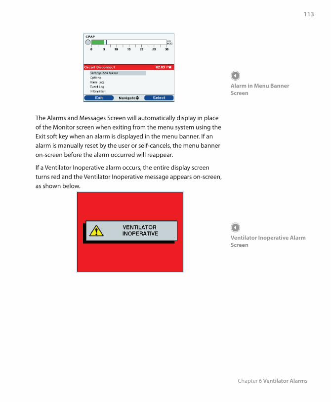
Chapter 6 Ventilator Alarms
113
The Alarms and Messages Screen will automatically display in place of the Monitor screen when exiting from the menu system using the Exit soft key when an alarm is displayed in the menu banner. If an alarm is manually reset by the user or self-cancels, the menu banner on-screen before the alarm occurred will reappear.
If a Ventilator Inoperative alarm occurs, the entire display screen turns red and the Ventilator Inoperative message appears on-screen, as shown below.
Alarm in Menu Banner Screen
Ventilator Inoperative Alarm Screen

Trilogy 202 clinical manual
114
To turn the ventilator off from a Ventilator Inoperative condition, use the normal power off sequence. When the Start/Stop button is selected, the following screen will display.
Select the Right button (Yes) to turn the ventilator off and stop the audible alarm. Selecting the Left button (No) will return the screen to the Ventilator Inoperative Alarm Screen without silencing the audible alarm.
Remote AlarmWhen the ventilator detects an alarm condition, if you are using a remote alarm system, a signal is sent from the ventilator to activate the remote alarm. The Remote Alarm is discussed in Chapter 4.
Ventilator Inoperative Power Off Screen
Chapter 6 Ventilator Alarms
115
Audio Pause and Alarm Reset Features
This section describes the Audio Pause and Alarm Reset features.
Audio PauseWhen an alarm occurs, you can temporarily silence the audible indicator by pressing the Alarm Indicator/Audio Pause button. The alarm is silenced for two minutes and then will sound again if the cause of the alarm has not been corrected. Each time the Alarm Indicator/Audio Pause button is pressed, the alarm silence period resets to two minutes.
When Audio Pause is active, the Alarm Indicator/Audio Pause symbol ( ) appears if you are on the Monitor screen. Additionally, an “Audio Pause” message displays in the menu banner on the Alarm Display screen.
You can ‘pre-silence’ alarms that have not yet occurred by pressing the Alarm Indicator/Audio Pause button while no alarms are active. Then, if an alarm occurs, the audible indicator does not sound until the Audio Pause time limit has expired. The LED and display will still show the alarm, but the audible alarm will not sound.
Alarm ResetThe Reset button is used to clear the currently active alarm(s) from the display and stop the LED and audible alarm indicator. This button should be selected after the situation causing the alarm(s) has been corrected. All active alarms are cancelled and alarm detection is restarted when this button is selected.
The ventilator self-cancels certain alarms if the cause of the alarm is corrected, shutting off the alarm LED, the audible alarm, and the alarm background color. However, the alarm text remains on the screen. You can manually reset an alarm by pressing the Left button (Reset). The Audio Pause function is cancelled if the alarm is manually reset.
Trilogy 202 clinical manual
116
Alarm Volume ControlAs explained in Chapter 5, you can adjust the Alarm Volume from the Options menu. You can select Loud or Soft, depending on your preference. The dB range of the alarms is from 47 dB to 92 dB.
What to Do When An Alarm Occurs
Complete the following steps when an alarm occurs:
1. Whenever an alarm occurs, first always observe the patient and ensure that adequate ventilation and oxygenation (if appropriate) are available.
2. Look at the alarm indicators and listen to the audible alarm sound. Note the color of the Alarm Indicator/Audio Pause button (red or yellow) and whether the LED is solid or flashing.
3. Look at the display to check the alarm message that appears on-screen and whether it is highlighted in red or yellow.
4. Press the Alarm Indicator/Audio Pause button to temporarily silence the audible alarm. A visual indicator displays if you are on the Monitor screen ( ), or an “Audio Pause” message appears in the menu banner on the Alarm Display screen.
5. Look up the alarm in the alarm descriptions later in this chapter to determine the source of the alarm and the appropriate action.
WARNING
Make sure the alarm volume is set loud enough to be heard by the caregiver. Consider the use of a remote alarm.
WARNINGYou should not rely on any single alarm to detect a circuit disconnect condition. The Low Tidal Volume, Low Minute Ventilation, Low Respiratory Rate, and Apnea alarms should be used in conjunction with the Circuit Disconnect alarm.
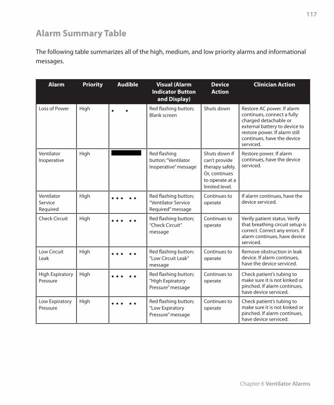
Chapter 6 Ventilator Alarms
117
Alarm Summary Table
The following table summarizes all of the high, medium, and low priority alarms and informational messages.
Alarm Priority Audible Visual (Alarm Indicator Button
and Display)
Device Action
Clinician Action
Loss of Power High • • Red flashing button; Blank screen
Shuts down Restore AC power. If alarm continues, connect a fully charged detachable or external battery to device to restore power. If alarm still continues, have the device serviced.
Ventilator Inoperative
High Red flashing button; “Ventilator Inoperative” message
Shuts down if can’t provide therapy safely. Or, continues to operate at a limited level.
Restore power. If alarm continues, have the device serviced.
Ventilator Service Required
High • • • • • Red flashing button; “Ventilator Service Required” message
Continues to operate
If alarm continues, have the device serviced.
Check Circuit High • • • • • Red flashing button; “Check Circuit” message
Continues to operate
Verify patient status. Verify that breathing circuit setup is correct. Correct any errors. If alarm continues, have device serviced.
Low Circuit Leak
High • • • • • Red flashing button; “Low Circuit Leak” message
Continues to operate
Remove obstruction in leak device. If alarm continues, have the device serviced.
High Expiratory Pressure
High • • • • • Red flashing button; “High Expiratory Pressure” message
Continues to operate
Check patient’s tubing to make sure it is not kinked or pinched. If alarm continues, have device serviced.
Low Expiratory Pressure
High • • • • • Red flashing button; “Low Expiratory Pressure” message
Continues to operate
Check patient’s tubing to make sure it is not kinked or pinched. If alarm continues, have device serviced.
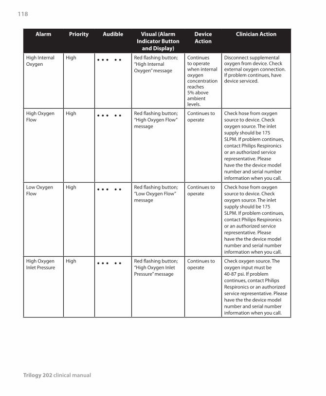
Trilogy 202 clinical manual
118
Alarm Priority Audible Visual (Alarm Indicator Button
and Display)
Device Action
Clinician Action
High Internal Oxygen
High • • • • • Red flashing button; “High Internal Oxygen” message
Continues to operate when internal oxygen concentration reaches 5% above ambient levels.
Disconnect supplemental oxygen from device. Check external oxygen connection. If problem continues, have device serviced.
High Oxygen Flow
High • • • • • Red flashing button; “High Oxygen Flow” message
Continues to operate
Check hose from oxygen source to device. Check oxygen source. The inlet supply should be 175 SLPM. If problem continues, contact Philips Respironics or an authorized service representative. Please have the the device model number and serial number information when you call.
Low Oxygen Flow
High • • • • • Red flashing button; “Low Oxygen Flow” message
Continues to operate
Check hose from oxygen source to device. Check oxygen source. The inlet supply should be 175 SLPM. If problem continues, contact Philips Respironics or an authorized service representative. Please have the the device model number and serial number information when you call.
High Oxygen Inlet Pressure
High • • • • • Red flashing button; “High Oxygen Inlet Pressure” message
Continues to operate
Check oxygen source. The oxygen input must be 40-87 psi. If problem continues, contact Philips Respironics or an authorized service representative. Please have the the device model number and serial number information when you call.
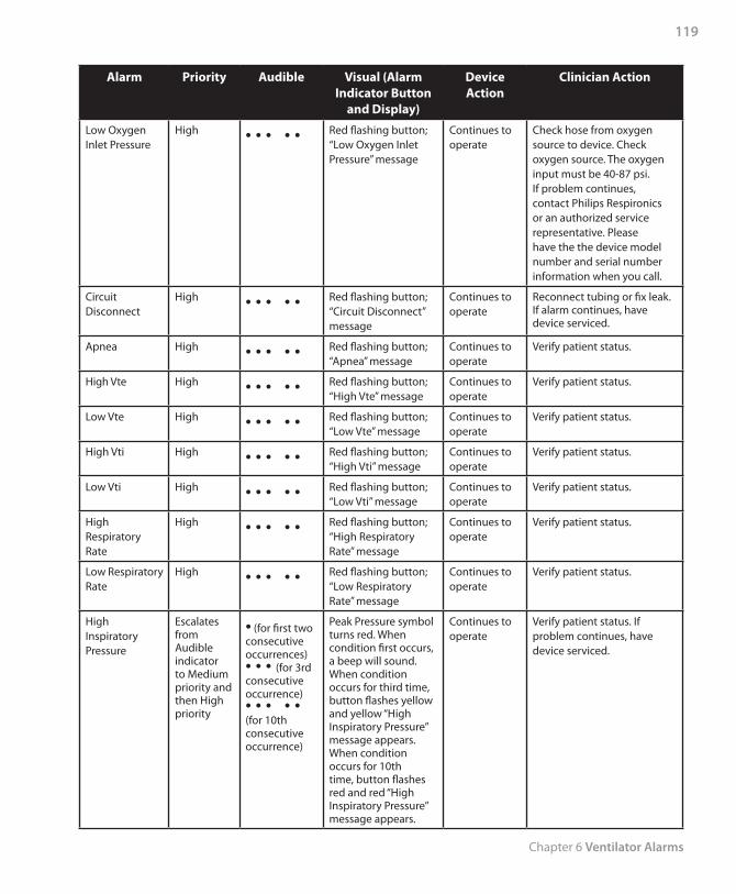
Chapter 6 Ventilator Alarms
119
Alarm Priority Audible Visual (Alarm Indicator Button
and Display)
Device Action
Clinician Action
Low Oxygen Inlet Pressure
High • • • • • Red flashing button; “Low Oxygen Inlet Pressure” message
Continues to operate
Check hose from oxygen source to device. Check oxygen source. The oxygen input must be 40-87 psi. If problem continues, contact Philips Respironics or an authorized service representative. Please have the the device model number and serial number information when you call.
Circuit Disconnect
High • • • • • Red flashing button; “Circuit Disconnect” message
Continues to operate
Reconnect tubing or fix leak. If alarm continues, have device serviced.
Apnea High • • • • • Red flashing button; “Apnea” message
Continues to operate
Verify patient status.
High Vte High • • • • • Red flashing button; “High Vte” message
Continues to operate
Verify patient status.
Low Vte High • • • • • Red flashing button; “Low Vte” message
Continues to operate
Verify patient status.
High Vti High • • • • • Red flashing button; “High Vti” message
Continues to operate
Verify patient status.
Low Vti High • • • • • Red flashing button; “Low Vti” message
Continues to operate
Verify patient status.
High Respiratory Rate
High • • • • • Red flashing button; “High Respiratory Rate” message
Continues to operate
Verify patient status.
Low Respiratory Rate
High • • • • • Red flashing button; “Low Respiratory Rate” message
Continues to operate
Verify patient status.
High Inspiratory Pressure
Escalates from Audible indicator to Medium priority and then High priority
• (for first two consecutive occurrences) • • • (for 3rd consecutive occurrence) • • • • • (for 10th consecutive occurrence)
Peak Pressure symbol turns red. When condition first occurs, a beep will sound. When condition occurs for third time, button flashes yellow and yellow “High Inspiratory Pressure” message appears. When condition occurs for 10th time, button flashes red and red “High Inspiratory Pressure” message appears.
Continues to operate
Verify patient status. If problem continues, have device serviced.
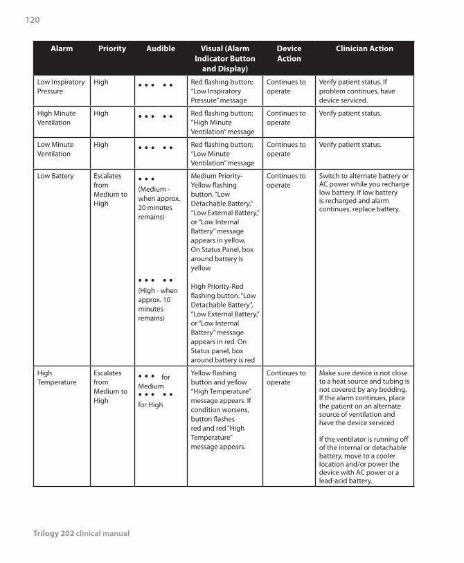
Trilogy 202 clinical manual
120
Alarm Priority Audible Visual (Alarm Indicator Button
and Display)
Device Action
Clinician Action
Low Inspiratory Pressure
High • • • • • Red flashing button; “Low Inspiratory Pressure” message
Continues to operate
Verify patient status. If problem continues, have device serviced.
High Minute Ventilation
High • • • • • Red flashing button; “High Minute Ventilation” message
Continues to operate
Verify patient status.
Low Minute Ventilation
High • • • • • Red flashing button; “Low Minute Ventilation” message
Continues to operate
Verify patient status.
Low Battery Escalates from Medium to High
• • • (Medium - when approx. 20 minutes remains)
• • • • • (High - when approx. 10 minutes remains)
Medium Priority-Yellow flashing button. “Low Detachable Battery,“ “Low External Battery,” or “Low Internal Battery” message appears in yellow, On Status Panel, box around battery is yellow
High Priority-Red flashing button. “Low Detachable Battery”, “Low External Battery,” or “Low Internal Battery” message appears in red. On Status panel, box around battery is red
Continues to operate
Switch to alternate battery or AC power while you recharge low battery. If low battery is recharged and alarm continues, replace battery.
High Temperature
Escalates from Medium to High
• • • for Medium • • • • • for High
Yellow flashing button and yellow “High Temperature” message appears. If condition worsens, button flashes red and red “High Temperature” message appears.
Continues to operate
Make sure device is not close to a heat source and tubing is not covered by any bedding. If the alarm continues, place the patient on an alternate source of ventilation and have the device serviced
If the ventilator is running off of the internal or detachable battery, move to a cooler location and/or power the device with AC power or a lead-acid battery.
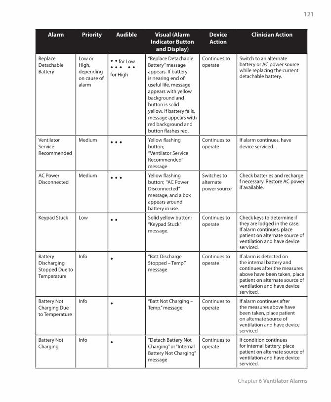
Chapter 6 Ventilator Alarms
121
Alarm Priority Audible Visual (Alarm Indicator Button
and Display)
Device Action
Clinician Action
Replace Detachable Battery
Low or High, depending on cause of alarm
• • for Low• • • • • for High
“Replace Detachable Battery” message appears. If battery is nearing end of useful life, message appears with yellow background and button is solid yellow. If battery fails, message appears with red background and button flashes red.
Continues to operate
Switch to an alternate battery or AC power source while replacing the current detachable battery.
Ventilator Service Recommended
Medium • • • Yellow flashing button; “Ventilator Service Recommended” message
Continues to operate
If alarm continues, have device serviced.
AC Power Disconnected
Medium • • • Yellow flashing button; “AC Power Disconnected” message, and a box appears around battery in use.
Switches to alternate power source
Check batteries and recharge f necessary. Restore AC power if available.
Keypad Stuck Low • • Solid yellow button; “Keypad Stuck” message.
Continues to operate
Check keys to determine if they are lodged in the case. If alarm continues, place patient on alternate source of ventilation and have device serviced.
Battery Discharging Stopped Due to Temperature
Info • “Batt Discharge Stopped – Temp.” message
Continues to operate
If alarm is detected on the internal battery and continues after the measures above have been taken, place patient on alternate source of ventilation and have device serviced.
Battery Not Charging Due to Temperature
Info • “Batt Not Charging – Temp.” message
Continues to operate
If alarm continues after the measures above have been taken, place patient on alternate source of ventilation and have device serviced
Battery Not Charging
Info • “Detach Battery Not Charging” or “Internal Battery Not Charging” message
Continues to operate
If condition continues for internal battery, place patient on alternate source of ventilation and have device serviced.
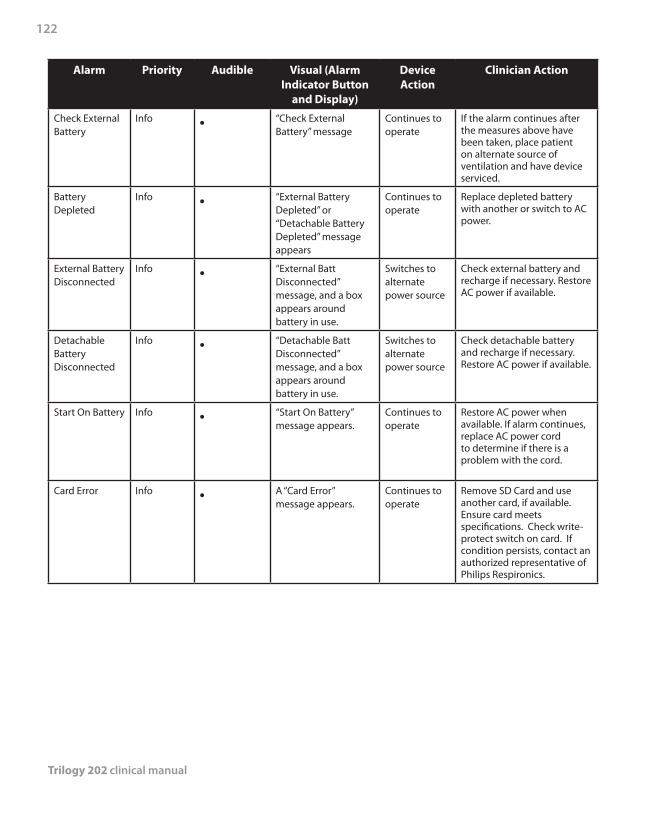
Trilogy 202 clinical manual
122
Alarm Priority Audible Visual (Alarm Indicator Button
and Display)
Device Action
Clinician Action
Check External Battery
Info • “Check External Battery” message
Continues to operate
If the alarm continues after the measures above have been taken, place patient on alternate source of ventilation and have device serviced.
Battery Depleted
Info • “External Battery Depleted” or “Detachable Battery Depleted” message appears
Continues to operate
Replace depleted battery with another or switch to AC power.
External Battery Disconnected
Info • “External Batt Disconnected” message, and a box appears around battery in use.
Switches to alternate power source
Check external battery and recharge if necessary. Restore AC power if available.
Detachable Battery Disconnected
Info • “Detachable Batt Disconnected” message, and a box appears around battery in use.
Switches to alternate power source
Check detachable battery and recharge if necessary. Restore AC power if available.
Start On Battery Info • “Start On Battery” message appears.
Continues to operate
Restore AC power when available. If alarm continues, replace AC power cord to determine if there is a problem with the cord.
Card Error Info • A “Card Error” message appears.
Continues to operate
Remove SD Card and use another card, if available. Ensure card meets specifications. Check write-protect switch on card. If condition persists, contact an authorized representative of Philips Respironics.
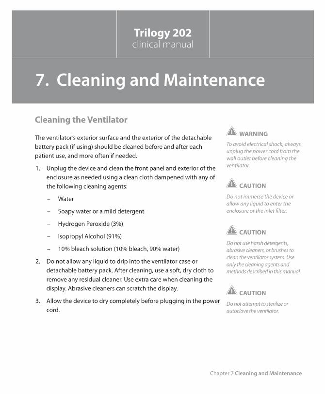
Chapter 7 Cleaning and Maintenance
123
Cleaning the Ventilator
The ventilator’s exterior surface and the exterior of the detachable battery pack (if using) should be cleaned before and after each patient use, and more often if needed.
1. Unplug the device and clean the front panel and exterior of the enclosure as needed using a clean cloth dampened with any of the following cleaning agents:
– Water
– Soapy water or a mild detergent
– Hydrogen Peroxide (3%)
– Isopropyl Alcohol (91%)
– 10% bleach solution (10% bleach, 90% water)
2. Do not allow any liquid to drip into the ventilator case or detachable battery pack. After cleaning, use a soft, dry cloth to remove any residual cleaner. Use extra care when cleaning the display. Abrasive cleaners can scratch the display.
3. Allow the device to dry completely before plugging in the power cord.
WARNING
To avoid electrical shock, always unplug the power cord from the wall outlet before cleaning the ventilator.
CAUTION
Do not immerse the device or allow any liquid to enter the enclosure or the inlet filter.
CAUTION
Do not use harsh detergents, abrasive cleaners, or brushes to clean the ventilator system. Use only the cleaning agents and methods described in this manual.
CAUTION
Do not attempt to sterilize or autoclave the ventilator.
Trilogy 202clinical manual
7. Cleaning and Maintenance
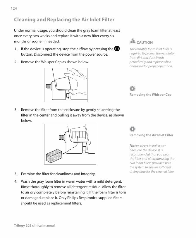
Trilogy 202 clinical manual
124
Cleaning and Replacing the Air Inlet Filter
Under normal usage, you should clean the gray foam filter at least once every two weeks and replace it with a new filter every six months or sooner if needed.
1. If the device is operating, stop the airflow by pressing the button. Disconnect the device from the power source.
2. Remove the Whisper Cap as shown below.
3. Remove the filter from the enclosure by gently squeezing the filter in the center and pulling it away from the device, as shown below.
3. Examine the filter for cleanliness and integrity.
4. Wash the gray foam filter in warm water with a mild detergent. Rinse thoroughly to remove all detergent residue. Allow the filter to air dry completely before reinstalling it. If the foam filter is torn or damaged, replace it. Only Philips Respironics-supplied filters should be used as replacement filters.
CAUTION
The reusable foam inlet filter is required to protect the ventilator from dirt and dust. Wash periodically and replace when damaged for proper operation.
Removing the Whisper Cap
Removing the Air Inlet Filter
Note: Never install a wet filter into the device. It is recommended that you clean the filter and alternate using the two foam filters provided with the system to ensure sufficient drying time for the cleaned filter.
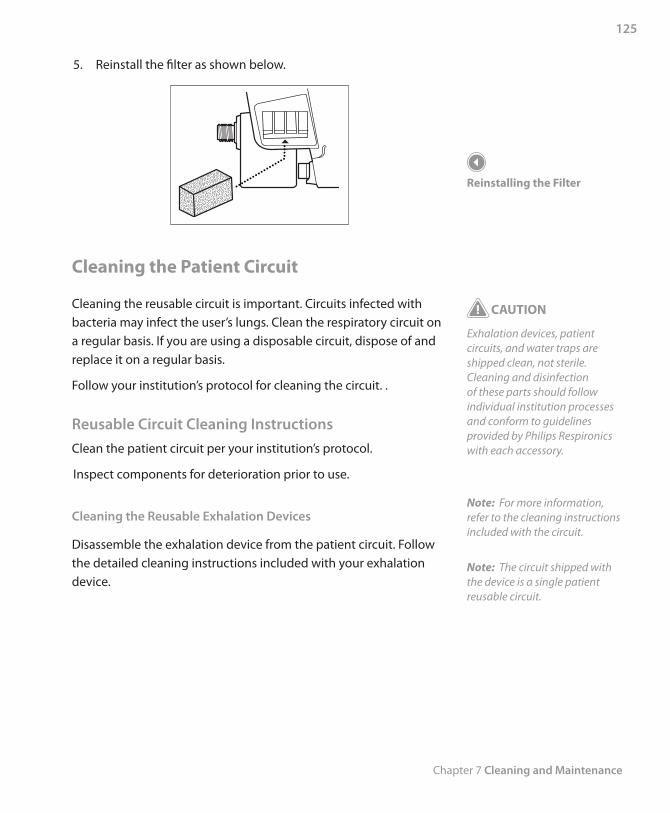
Chapter 7 Cleaning and Maintenance
125
5. Reinstall the filter as shown below.
Cleaning the Patient Circuit
Cleaning the reusable circuit is important. Circuits infected with bacteria may infect the user’s lungs. Clean the respiratory circuit on a regular basis. If you are using a disposable circuit, dispose of and replace it on a regular basis.
Follow your institution’s protocol for cleaning the circuit. .
Reusable Circuit Cleaning Instructions Clean the patient circuit per your institution’s protocol.
Inspect components for deterioration prior to use.
Cleaning the Reusable Exhalation Devices
Disassemble the exhalation device from the patient circuit. Follow the detailed cleaning instructions included with your exhalation device.
Reinstalling the Filter
CAUTION
Exhalation devices, patient circuits, and water traps are shipped clean, not sterile. Cleaning and disinfection of these parts should follow individual institution processes and conform to guidelines provided by Philips Respironics with each accessory.
Note: For more information, refer to the cleaning instructions included with the circuit.
Note: The circuit shipped with the device is a single patient reusable circuit.
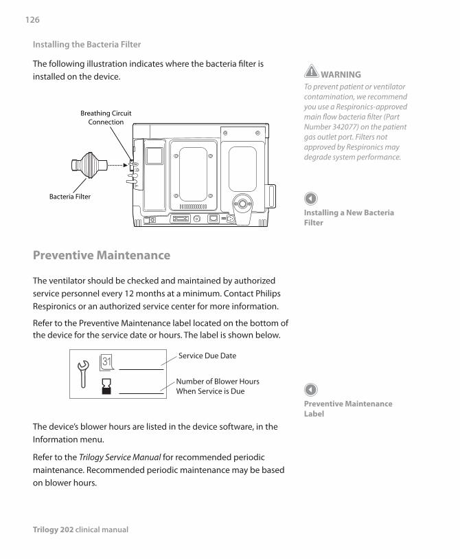
Trilogy 202 clinical manual
126
WARNINGTo prevent patient or ventilator contamination, we recommend you use a Respironics-approved main flow bacteria filter (Part Number 342077) on the patient gas outlet port. Filters not approved by Respironics may degrade system performance.
Installing a New Bacteria Filter
Preventive Maintenance Label
Installing the Bacteria Filter
The following illustration indicates where the bacteria filter is installed on the device.
Preventive Maintenance
The ventilator should be checked and maintained by authorized service personnel every 12 months at a minimum. Contact Philips Respironics or an authorized service center for more information.
Refer to the Preventive Maintenance label located on the bottom of the device for the service date or hours. The label is shown below.
Service Due Date
Number of Blower HoursWhen Service is Due
The device’s blower hours are listed in the device software, in the Information menu.
Refer to the Trilogy Service Manual for recommended periodic maintenance. Recommended periodic maintenance may be based on blower hours.
Chapter 8 Troubleshooting
127
The ventilator is designed to respond to most issues with an appropriate alarm or information message. These messages appear on the display screen. Chapter 6 describes many of the alarms and what action you should take when the alarms occur.
This chapter provides additional troubleshooting information for other common issues you may have.
Issue Why It Happened What To Do
Device does not turn on.Nothing happens when you press Start/Stop to begin therapy. The audible indicator does not sound and the backlights on the buttons do not light.
The AC power cord is not plugged in and the internal battery is not charged.Note: The device requires AC power to charge the internal battery when a new device is powered up for the first time.
Plug the AC power cord into the device and a wall outlet that is not controlled by a switch. This powers the system and charges the internal battery. If the device still does not turn on, contact an authorized service representative or Philips Respironics to have the device serviced. Please have the model number and serial number ready when you call.
Trilogy 202clinical manual
8. Troubleshooting
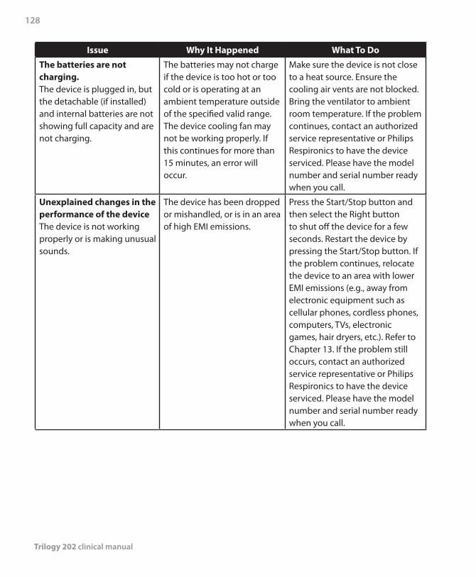
Trilogy 202 clinical manual
128
Issue Why It Happened What To Do
The batteries are not charging.The device is plugged in, but the detachable (if installed) and internal batteries are not showing full capacity and are not charging.
The batteries may not charge if the device is too hot or too cold or is operating at an ambient temperature outside of the specified valid range. The device cooling fan may not be working properly. If this continues for more than 15 minutes, an error will occur.
Make sure the device is not close to a heat source. Ensure the cooling air vents are not blocked. Bring the ventilator to ambient room temperature. If the problem continues, contact an authorized service representative or Philips Respironics to have the device serviced. Please have the model number and serial number ready when you call.
Unexplained changes in the performance of the deviceThe device is not working properly or is making unusual sounds.
The device has been dropped or mishandled, or is in an area of high EMI emissions.
Press the Start/Stop button and then select the Right button to shut off the device for a few seconds. Restart the device by pressing the Start/Stop button. If the problem continues, relocate the device to an area with lower EMI emissions (e.g., away from electronic equipment such as cellular phones, cordless phones, computers, TVs, electronic games, hair dryers, etc.). Refer to Chapter 13. If the problem still occurs, contact an authorized service representative or Philips Respironics to have the device serviced. Please have the model number and serial number ready when you call.
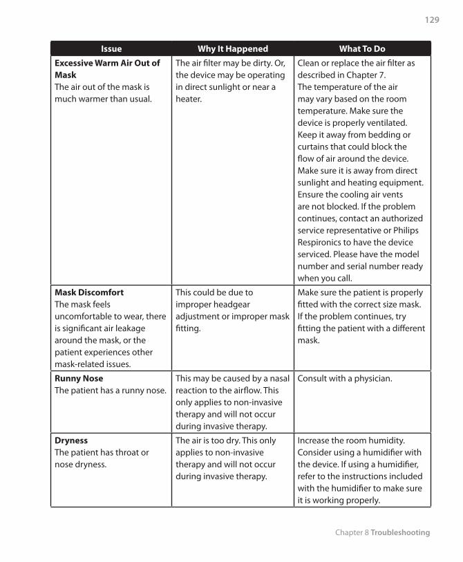
Chapter 8 Troubleshooting
129
Issue Why It Happened What To Do
Excessive Warm Air Out of Mask The air out of the mask is much warmer than usual.
The air filter may be dirty. Or, the device may be operating in direct sunlight or near a heater.
Clean or replace the air filter as described in Chapter 7. The temperature of the air may vary based on the room temperature. Make sure the device is properly ventilated. Keep it away from bedding or curtains that could block the flow of air around the device. Make sure it is away from direct sunlight and heating equipment. Ensure the cooling air vents are not blocked. If the problem continues, contact an authorized service representative or Philips Respironics to have the device serviced. Please have the model number and serial number ready when you call.
Mask Discomfort The mask feels uncomfortable to wear, there is significant air leakage around the mask, or the patient experiences other mask-related issues.
This could be due to improper headgear adjustment or improper mask fitting.
Make sure the patient is properly fitted with the correct size mask. If the problem continues, try fitting the patient with a different mask.
Runny NoseThe patient has a runny nose.
This may be caused by a nasal reaction to the airflow. This only applies to non-invasive therapy and will not occur during invasive therapy.
Consult with a physician.
DrynessThe patient has throat or nose dryness.
The air is too dry. This only applies to non-invasive therapy and will not occur during invasive therapy.
Increase the room humidity. Consider using a humidifier with the device. If using a humidifier, refer to the instructions included with the humidifier to make sure it is working properly.
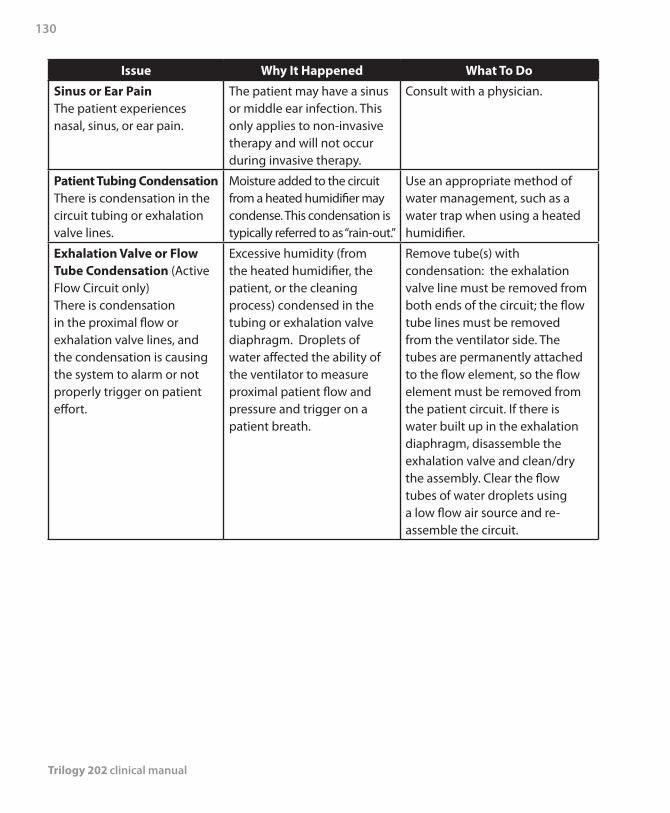
Trilogy 202 clinical manual
130
Issue Why It Happened What To Do
Sinus or Ear PainThe patient experiences nasal, sinus, or ear pain.
The patient may have a sinus or middle ear infection. This only applies to non-invasive therapy and will not occur during invasive therapy.
Consult with a physician.
Patient Tubing CondensationThere is condensation in the circuit tubing or exhalation valve lines.
Moisture added to the circuit from a heated humidifier may condense. This condensation is typically referred to as “rain-out.”
Use an appropriate method of water management, such as a water trap when using a heated humidifier.
Exhalation Valve or Flow Tube Condensation (Active Flow Circuit only)There is condensation in the proximal flow or exhalation valve lines, and the condensation is causing the system to alarm or not properly trigger on patient effort.
Excessive humidity (from the heated humidifier, the patient, or the cleaning process) condensed in the tubing or exhalation valve diaphragm. Droplets of water affected the ability of the ventilator to measure proximal patient flow and pressure and trigger on a patient breath.
Remove tube(s) with condensation: the exhalation valve line must be removed from both ends of the circuit; the flow tube lines must be removed from the ventilator side. The tubes are permanently attached to the flow element, so the flow element must be removed from the patient circuit. If there is water built up in the exhalation diaphragm, disassemble the exhalation valve and clean/dry the assembly. Clear the flow tubes of water droplets using a low flow air source and re-assemble the circuit.
Chapter 9 Accessories
131
There are several accessories you can use with the ventilator.
Adding a Humidifier
Use of a humidifier may reduce nasal dryness and irritation by adding moisture to the airflow.
If you are using a humidifier with the ventilator, refer to the instructions provided with the humidifier for complete setup information.
Adding Supplemental Oxygen to the Device
This ventilator is equipped with an oxygen blending module which allows oxygen to be delivered to the patient within a range of 21% to 100% concentration.
Circuit leak rate may have an impact on FiO2.
The Trilogy O2 should be connected to an oxygen gas pipeline that complies with national country regulations.
The oxygen input to the device must be:
Pressure: 40 psi to 87 psi •Flow: 175 SLPM •
Trilogy 202clinical manual
9. Accessories
Trilogy 202 clinical manual
132
Please note the warnings listed below when using oxygen with the device.
Oxygen Blending Module WarningsTo ensure accuracy of oxygen administration and to •monitor for the presence of contamination (incorrect gas connected), use an external oxygen monitor to verify the oxygen concentration in the delivered gas.
This device is equipped with an oxygen blending module •which allows oxygen to be delivered to the patient within a range of 21-100% concentration.Contents under pressure. Do not remove the oxygen inlet •cap while still connected to oxygen source. Removing the cap may cause it to pop off and cause injury.
Fixed Flow Oxygen WarningsWhen administering fixed-flow supplemental oxygen, •the oxygen concentration may not be constant. The inspired oxygen concentration will vary, depending on the pressures, patient flows and circuit leak. Substantial leaks may reduce the inspired oxygen concentration to less than the expected value. Appropriate patient monitoring should be used, as medically indicated, such as an alarming pulse oximeter.
Do not connect the device to an unregulated oxygen •source.
Oxygen supports combustion. Oxygen should not be •used while smoking or in the presence of an open flame.
If oxygen is used with the device, the oxygen flow must •be turned off when the device is not in use. Explanation of the Warning: When the device is not in operation and the oxygen flow is left on, oxygen delivered into the tubing may accumulate within the device’s enclosure.
The ventilator should not be operated in the presence of •flammable gasses. This could cause a fire or explosion.
Chapter 9 Accessories
133
Using a Remote Alarm Unit
You can use a Philips Respironics Remote Alarm unit with your device. There is a dedicated adapter cable assembly for connecting the device to the Remote Alarm unit (REF 1045291). Refer to the instructions included with your Remote Alarm unit and adapter cable assembly if you have questions on how to use it with device.
WARNING
The remote alarm should be tested daily. When using a remote alarm, make sure you fully test the remote alarm connector and cable by verifying that:
- Annunciated alarms on the ventilator are also annunciated on the remote alarm.
- Disconnecting the remote alarm cable from the ventilator or from the remote alarm results in an alarm notification at the remote alarm.
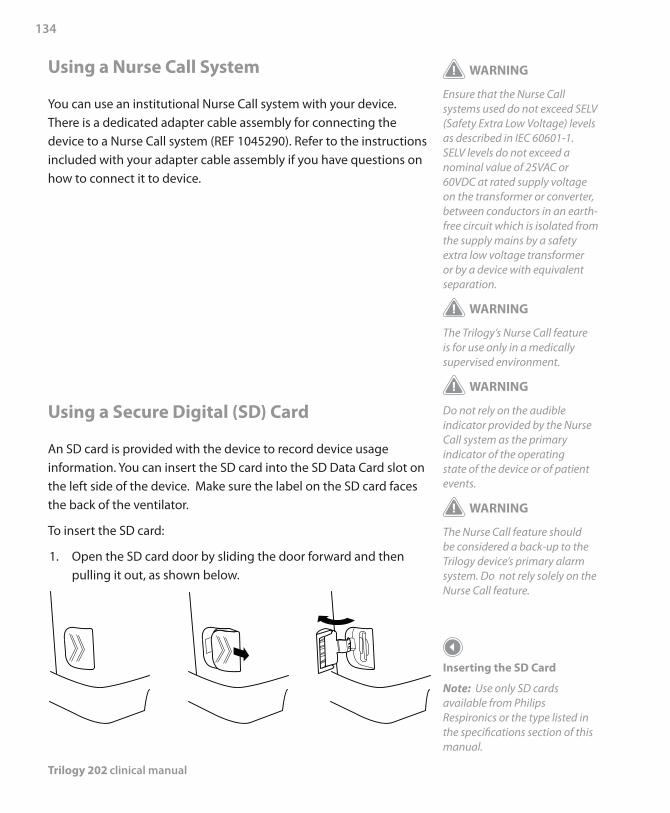
Trilogy 202 clinical manual
134
Using a Nurse Call System
You can use an institutional Nurse Call system with your device. There is a dedicated adapter cable assembly for connecting the device to a Nurse Call system (REF 1045290). Refer to the instructions included with your adapter cable assembly if you have questions on how to connect it to device.
Using a Secure Digital (SD) Card
An SD card is provided with the device to record device usage information. You can insert the SD card into the SD Data Card slot on the left side of the device. Make sure the label on the SD card faces the back of the ventilator.
To insert the SD card:
1. Open the SD card door by sliding the door forward and then pulling it out, as shown below.
Inserting the SD Card
Note: Use only SD cards available from Philips Respironics or the type listed in the specifications section of this manual.
WARNING
Ensure that the Nurse Call systems used do not exceed SELV (Safety Extra Low Voltage) levels as described in IEC 60601-1. SELV levels do not exceed a nominal value of 25VAC or 60VDC at rated supply voltage on the transformer or converter, between conductors in an earth-free circuit which is isolated from the supply mains by a safety extra low voltage transformer or by a device with equivalent separation.
WARNING
The Trilogy’s Nurse Call feature is for use only in a medically supervised environment.
WARNING
Do not rely on the audible indicator provided by the Nurse Call system as the primary indicator of the operating state of the device or of patient events.
WARNING
The Nurse Call feature should be considered a back-up to the Trilogy device’s primary alarm system. Do not rely solely on the Nurse Call feature.
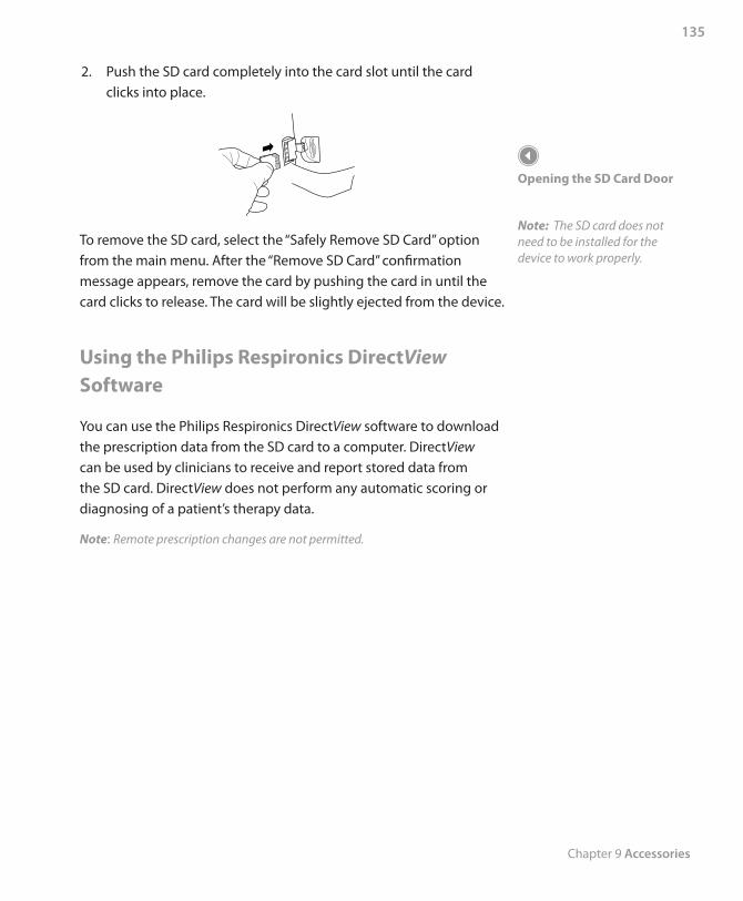
Chapter 9 Accessories
135
2. Push the SD card completely into the card slot until the card clicks into place.
To remove the SD card, select the “Safely Remove SD Card” option from the main menu. After the “Remove SD Card” confirmation message appears, remove the card by pushing the card in until the card clicks to release. The card will be slightly ejected from the device.
Using the Philips Respironics DirectView Software
You can use the Philips Respironics DirectView software to download the prescription data from the SD card to a computer. DirectView can be used by clinicians to receive and report stored data from the SD card. DirectView does not perform any automatic scoring or diagnosing of a patient’s therapy data.
Note: Remote prescription changes are not permitted.
Opening the SD Card Door
Note: The SD card does not need to be installed for the device to work properly.

Trilogy 202 clinical manual
136
Chapter 10 System Checkout Procedures
137
This chapter details the test procedures that should be performed by the clinician prior to connecting the device to the patient. Test the Active PAP, Active Flow, and Passive circuit types if you want to do a complete checkout on the device. The tests should be performed as described in order to verify proper operation of the device. Some of the procedures in this chapter require you to change settings on the device. If you are not familiar with the procedures for accomplishing this, please refer to Chapter 4, Ventilator Setup and Chapter 5, Viewing and Changing Settings.
Tools Required
Universal Porting Block •Active PAP Exhalation Device •Active Flow Exhalation Device with Flow Sensor •Trilogy Universal Active PAP Tube Adapter •Passive Exhalation Device •Test Lung •High Pressure O • 2 Hose
Oxygen Monitor •Small Flat Head Screwdriver •
Trilogy 202clinical manual
10. System Checkout Procedures
Note: The actual circuit configuration to be used on the patient should be used to perform the system checkout procedure.
WARNING
If you notice any unexplained changes in the performance of the device, if it is making unusual sounds, if the device or detachable battery are dropped, if water is spilled into the enclosure, or if the enclosure is cracked or broken, discontinue use and contact Philips Respironics or an authorized service center for service.
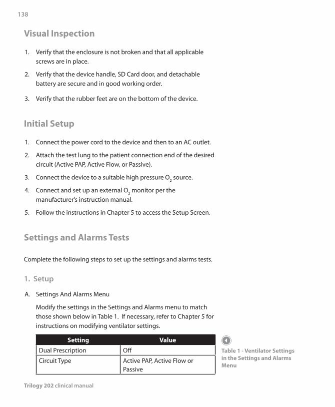
Trilogy 202 clinical manual
138
Visual Inspection
1. Verify that the enclosure is not broken and that all applicable screws are in place.
2. Verify that the device handle, SD Card door, and detachable battery are secure and in good working order.
3. Verify that the rubber feet are on the bottom of the device.
Initial Setup
1. Connect the power cord to the device and then to an AC outlet.
2. Attach the test lung to the patient connection end of the desired circuit (Active PAP, Active Flow, or Passive).
3. Connect the device to a suitable high pressure O2 source.
4. Connect and set up an external O2 monitor per the manufacturer’s instruction manual.
5. Follow the instructions in Chapter 5 to access the Setup Screen.
Settings and Alarms Tests
Complete the following steps to set up the settings and alarms tests.
1. Setup
A. Settings And Alarms Menu
Modify the settings in the Settings and Alarms menu to match those shown below in Table 1. If necessary, refer to Chapter 5 for instructions on modifying ventilator settings.
Setting Value
Dual Prescription Off
Circuit Type Active PAP, Active Flow or Passive
Table 1 - Ventilator Settings in the Settings and Alarms Menu
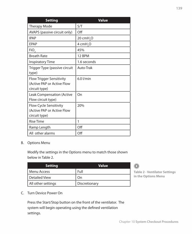
Chapter 10 System Checkout Procedures
139
Setting Value
Therapy Mode S/T
AVAPS (passive circuit only) Off
IPAP 20 cmH2O
EPAP 4 cmH2O
FiO2 45%
Breath Rate 12 BPM
Inspiratory Time 1.6 seconds
Trigger Type (passive circuit type)
Auto-Trak
Flow Trigger Sensitivity (Active PAP or Active Flow circuit type)
6.0 l/min
Leak Compensation (Active Flow circuit type)
On
Flow Cycle Sensitivity (Active PAP or Active Flow circuit type)
20%
Rise Time 1
Ramp Length Off
All other alarms Off
B. Options Menu
Modify the settings in the Options menu to match those shown below in Table 2.
Setting Value
Menu Access Full
Detailed View On
All other settings Discretionary
C. Turn Device Power On
Press the Start/Stop button on the front of the ventilator. The system will begin operating using the defined ventilation settings.
Table 2 - Ventilator Settings in the Options Menu
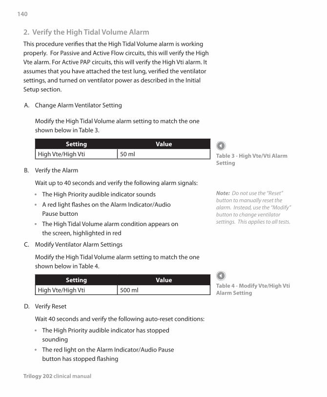
Trilogy 202 clinical manual
140
2. Verify the High Tidal Volume AlarmThis procedure verifies that the High Tidal Volume alarm is working properly. For Passive and Active Flow circuits, this will verify the High Vte alarm. For Active PAP circuits, this will verify the High Vti alarm. It assumes that you have attached the test lung, verified the ventilator settings, and turned on ventilator power as described in the Initial Setup section.
A. Change Alarm Ventilator Setting
Modify the High Tidal Volume alarm setting to match the one shown below in Table 3.
Setting Value
High Vte/High Vti 50 ml
B. Verify the Alarm
Wait up to 40 seconds and verify the following alarm signals:
The High Priority audible indicator sounds •A red light flashes on the • Alarm Indicator/Audio Pause button
The High Tidal Volume alarm condition appears on •the screen, highlighted in red
C. Modify Ventilator Alarm Settings
Modify the High Tidal Volume alarm setting to match the one shown below in Table 4.
Setting Value
High Vte/High Vti 500 ml
D. Verify Reset
Wait 40 seconds and verify the following auto-reset conditions:
The High Priority audible indicator has stopped •sounding
The red light on the • Alarm Indicator/Audio Pause button has stopped flashing
Table 3 - High Vte/Vti Alarm Setting
Note: Do not use the “Reset” button to manually reset the alarm. Instead, use the “Modify” button to change ventilator settings. This applies to all tests.
Table 4 - Modify Vte/High Vti Alarm Setting
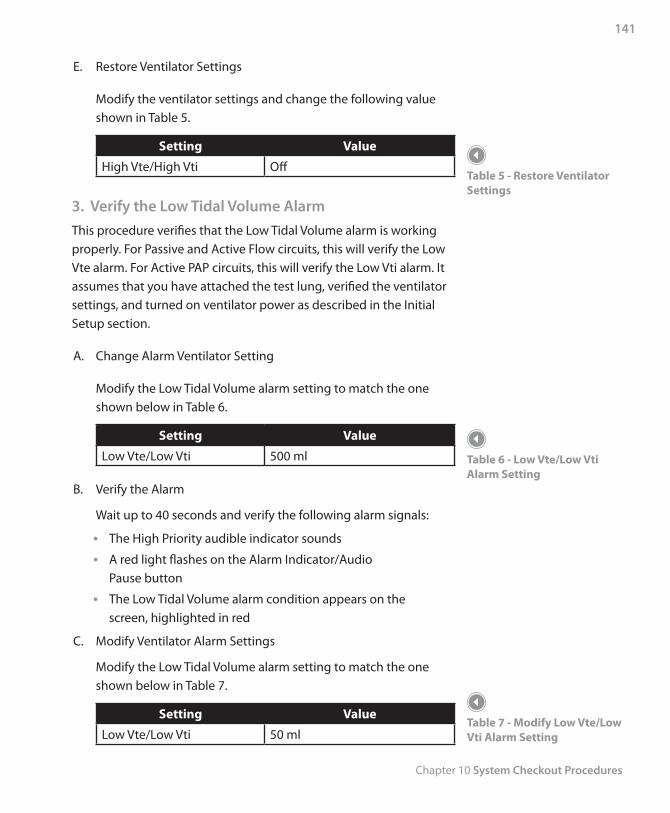
Chapter 10 System Checkout Procedures
141
E. Restore Ventilator Settings
Modify the ventilator settings and change the following value shown in Table 5.
Setting Value
High Vte/High Vti Off
3. Verify the Low Tidal Volume AlarmThis procedure verifies that the Low Tidal Volume alarm is working properly. For Passive and Active Flow circuits, this will verify the Low Vte alarm. For Active PAP circuits, this will verify the Low Vti alarm. It assumes that you have attached the test lung, verified the ventilator settings, and turned on ventilator power as described in the Initial Setup section.
A. Change Alarm Ventilator Setting
Modify the Low Tidal Volume alarm setting to match the one shown below in Table 6.
Setting Value
Low Vte/Low Vti 500 ml
B. Verify the Alarm
Wait up to 40 seconds and verify the following alarm signals:
The High Priority audible indicator sounds •A red light flashes on the • Alarm Indicator/Audio Pause button
The Low Tidal Volume alarm condition appears on the •screen, highlighted in red
C. Modify Ventilator Alarm Settings
Modify the Low Tidal Volume alarm setting to match the one shown below in Table 7.
Setting Value
Low Vte/Low Vti 50 ml
Table 5 - Restore Ventilator Settings
Table 6 - Low Vte/Low Vti Alarm Setting
Table 7 - Modify Low Vte/Low Vti Alarm Setting
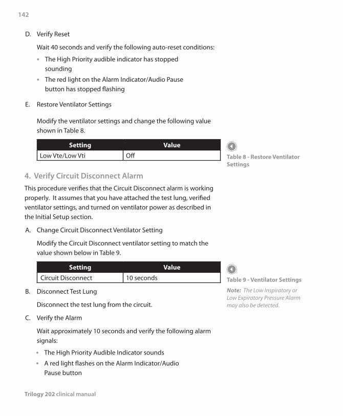
Trilogy 202 clinical manual
142
D. Verify Reset
Wait 40 seconds and verify the following auto-reset conditions:
The High Priority audible indicator has stopped •sounding
The red light on the • Alarm Indicator/Audio Pause button has stopped flashing
E. Restore Ventilator Settings
Modify the ventilator settings and change the following value shown in Table 8.
Setting Value
Low Vte/Low Vti Off
4. Verify Circuit Disconnect AlarmThis procedure verifies that the Circuit Disconnect alarm is working properly. It assumes that you have attached the test lung, verified ventilator settings, and turned on ventilator power as described in the Initial Setup section.
A. Change Circuit Disconnect Ventilator Setting
Modify the Circuit Disconnect ventilator setting to match the value shown below in Table 9.
Setting Value
Circuit Disconnect 10 seconds
B. Disconnect Test Lung
Disconnect the test lung from the circuit.
C. Verify the Alarm
Wait approximately 10 seconds and verify the following alarm signals:
The High Priority Audible Indicator sounds •A red light flashes on the • Alarm Indicator/Audio Pause button
Table 8 - Restore Ventilator Settings
Table 9 - Ventilator Settings
Note: The Low Inspiratory or Low Expiratory Pressure Alarm may also be detected.
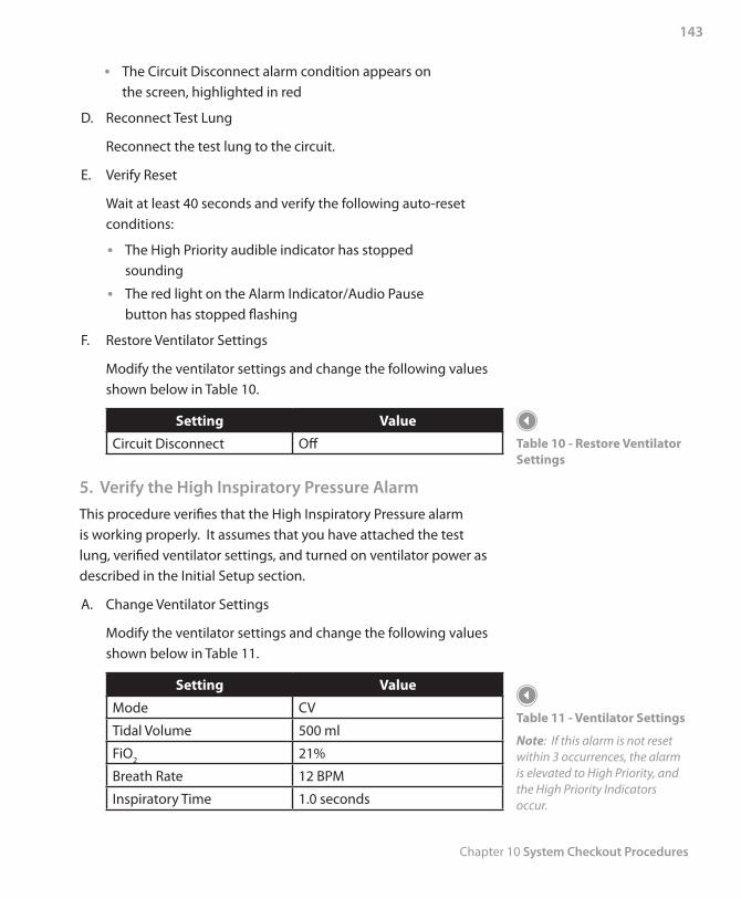
Chapter 10 System Checkout Procedures
143
The Circuit Disconnect alarm condition appears on •the screen, highlighted in red
D. Reconnect Test Lung
Reconnect the test lung to the circuit.
E. Verify Reset
Wait at least 40 seconds and verify the following auto-reset conditions:
The High Priority audible indicator has stopped •sounding
The red light on the • Alarm Indicator/Audio Pause button has stopped flashing
F. Restore Ventilator Settings
Modify the ventilator settings and change the following values shown below in Table 10.
Setting Value
Circuit Disconnect Off
5. Verify the High Inspiratory Pressure AlarmThis procedure verifies that the High Inspiratory Pressure alarm is working properly. It assumes that you have attached the test lung, verified ventilator settings, and turned on ventilator power as described in the Initial Setup section.
A. Change Ventilator Settings
Modify the ventilator settings and change the following values shown below in Table 11.
Setting Value
Mode CV
Tidal Volume 500 ml
FiO2 21%
Breath Rate 12 BPM
Inspiratory Time 1.0 seconds
Table 10 - Restore Ventilator Settings
Table 11 - Ventilator Settings
Note: If this alarm is not reset within 3 occurrences, the alarm is elevated to High Priority, and the High Priority Indicators occur.

Trilogy 202 clinical manual
144
Setting Value
Flow Pattern Ramp
PEEP 4 cmH2O
Sigh Off
Circuit Disconnect Off
Low Inspiratory Pressure 6 cmH2O
High Inspiratory Pressure 10 cmH2O
Apnea Off
All other alarms Off
B. Verify the Alarm
Wait up to 40 seconds and verify the following alarm signals:
The Medium Priority audible indicator sounds •A yellow light flashes on the • Alarm Indicator/Audio Pause button
The High Inspiratory Pressure alarm condition •appears on the screen, highlighted in yellow
C. Modify Ventilator Alarm Settings
Modify the High Inspiratory Pressure setting to match the one shown below in Table 12.
Setting Value
High Inspiratory Pressure 60 cmH2O
D. Verify Reset
Wait 40 seconds and verify the following auto-reset conditions:
The Medium Priority audible indicator has stopped •sounding
The yellow light on the • Alarm Indicator/Audio Pause button has stopped flashing
Table 12 - Modify High Inspiratory Pressure Alarm Setting
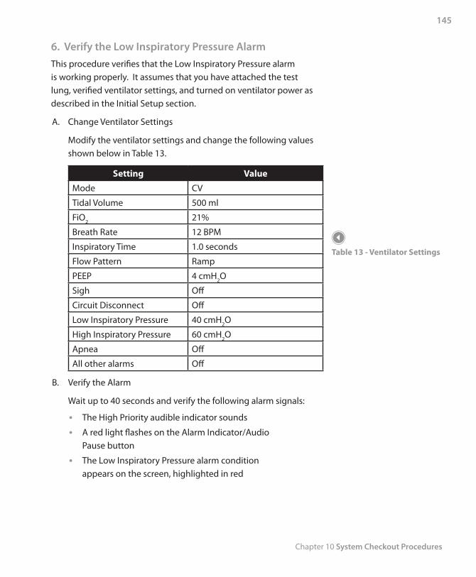
Chapter 10 System Checkout Procedures
145
6. Verify the Low Inspiratory Pressure AlarmThis procedure verifies that the Low Inspiratory Pressure alarm is working properly. It assumes that you have attached the test lung, verified ventilator settings, and turned on ventilator power as described in the Initial Setup section.
A. Change Ventilator Settings
Modify the ventilator settings and change the following values shown below in Table 13.
Setting Value
Mode CV
Tidal Volume 500 ml
FiO2 21%
Breath Rate 12 BPM
Inspiratory Time 1.0 seconds
Flow Pattern Ramp
PEEP 4 cmH2O
Sigh Off
Circuit Disconnect Off
Low Inspiratory Pressure 40 cmH2O
High Inspiratory Pressure 60 cmH2O
Apnea Off
All other alarms Off
B. Verify the Alarm
Wait up to 40 seconds and verify the following alarm signals:
The High Priority audible indicator sounds •A red light flashes on the • Alarm Indicator/Audio Pause button
The Low Inspiratory Pressure alarm condition •appears on the screen, highlighted in red
Table 13 - Ventilator Settings
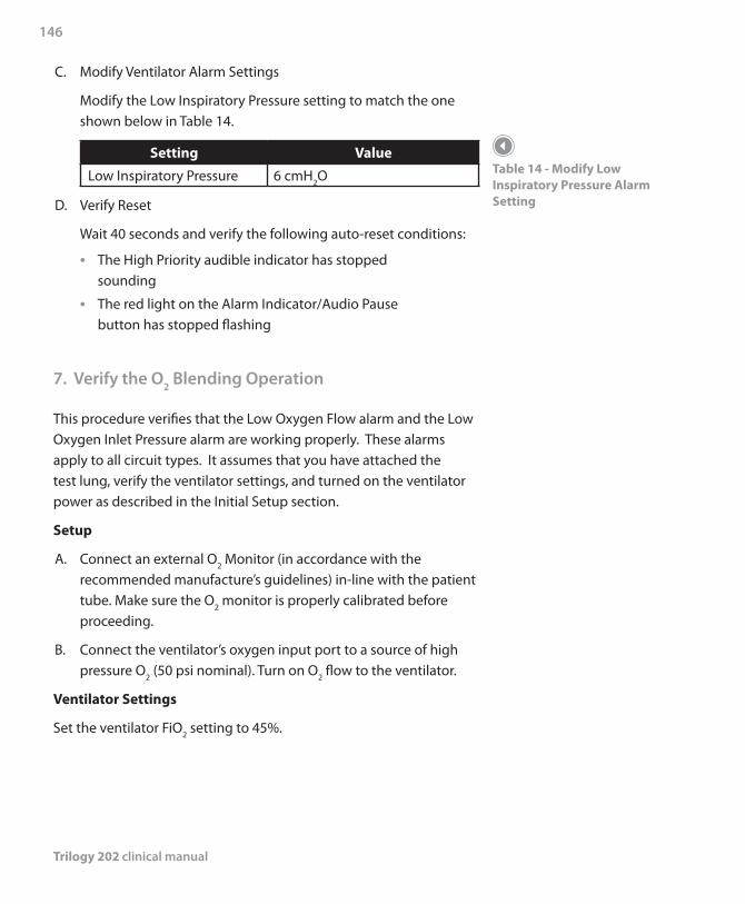
Trilogy 202 clinical manual
146
C. Modify Ventilator Alarm Settings
Modify the Low Inspiratory Pressure setting to match the one shown below in Table 14.
Setting Value
Low Inspiratory Pressure 6 cmH2O
D. Verify Reset
Wait 40 seconds and verify the following auto-reset conditions:
The High Priority audible indicator has stopped •sounding
The red light on the • Alarm Indicator/Audio Pause button has stopped flashing
7. Verify the O2 Blending Operation
This procedure verifies that the Low Oxygen Flow alarm and the Low Oxygen Inlet Pressure alarm are working properly. These alarms apply to all circuit types. It assumes that you have attached the test lung, verify the ventilator settings, and turned on the ventilator power as described in the Initial Setup section.
Setup
A. Connect an external O2 Monitor (in accordance with the recommended manufacture’s guidelines) in-line with the patient tube. Make sure the O2 monitor is properly calibrated before proceeding.
B. Connect the ventilator’s oxygen input port to a source of high pressure O2 (50 psi nominal). Turn on O2 flow to the ventilator.
Ventilator Settings
Set the ventilator FiO2 setting to 45%.
Table 14 - Modify Low Inspiratory Pressure Alarm Setting
Chapter 10 System Checkout Procedures
147
Verify Blending
A. Turn on the ventilator.
B. Verify the set level of FiO2 is satisfied using an external O2 monitor.
Verify alarm
A. Shut off or disconnect the source of high pressure O2 to the ventilator.
B. Wait 1 minute and verify the following alarm signals:
The Priority audible indicator sounds. •A red light flashes on the Alarm Indicator/Audio •Pause Button.
The following alarm conditions appear on the screen, •highlighted in red:
- Low Oxygen Flow
- Low Oxygen Inlet Pressure
Verify Reset
A. Reconnect or turn on the source of high pressure O2 to the ventilator.
B. Wait 1 minute and verify the following:
The set level of FiO • 2 is satisfied using an external O2 monitor.
The High Priority audible indicator has stopped •sounding.
The red light on the Alarm Indicator/Audio Pause •button has stopped flashing.
Trilogy 202 clinical manual
148
Battery Function Verification
Make sure the batteries are functioning properly and fully charged before patient use.
1. Verify the Detachable and Internal (Lithium-Ion)
Batteries FunctionA. Connect AC Power to the device and verify that the green AC
LED on the front panel is lit.
B. Verify that the detachable battery is properly installed.
C. Turn the device on and verify that both the detachable and internal battery symbols appear on the display. Verify that if either battery is less than fully charged, the charge symbol will display on the respective battery.
D. Disconnect the AC Power source from the device.
Verify that the AC Power Disconnected alarm •message appears on the display and the green AC LED is not lit. Press Reset.
Verify that the detachable battery symbol shows the •level of charge noted in the previous step and that the device continues to operate.
Verify that the detachable battery symbol has a black •box around it to indicate that it is in use.
E. Disconnect the detachable battery pack from the device.
Verify that the Detach Batt Disconnected alarm •message appears on the display. Press Reset.
Verify that the internal battery symbol shows the •same level of charge as noted in Step C and the device continues to operate.
Verify that the internal battery symbol has a black •box around it to indicate that it is in use.
F. Reconnect the Detachable Battery and AC Power source.
Chapter 10 System Checkout Procedures
149
2. Verify the External Battery Function (If Available)A. Connect AC Power to the device and verify that the green AC
LED is lit.
B. Connect the external battery cable to the external battery and to the ventilator.
C. Verify that the external battery symbol is shown on the display and some level of charge is present.
D. Disconnect the AC Power source from the device.
Verify that the AC Power Disconnected alarm •message appears on the display and the green AC LED is not lit. Press Reset.
Verify that the external battery symbol shows the •level of charge as noted in the previous step and the device continues to operate.
Verify that the external battery symbol has a black •box around it to indicate that it is in use.
E. Reconnect the AC Power source.
Alarm and Event Log Clean-Up
1. In the Setup Menu, select Alarm Log.
A. Press Clear to clear the log file.
B. Press Yes to confirm.
C. Press Finish to complete.
2. In the Setup Menu, select Event Log.
A. Press Clear to clear the log file.
B. Press Yes to confirm.
C. Press Finish to complete.
Trilogy 202 clinical manual
150
Results
All portions of this checkout procedure should be completed prior to connection to the patient. If any of the tests fail to complete as indicated, if possible, correct the error, clear the alarm and resume testing. If correction of the failed portion is not possible, return the device to Philips Respironics or an authorized service center for service and repair.
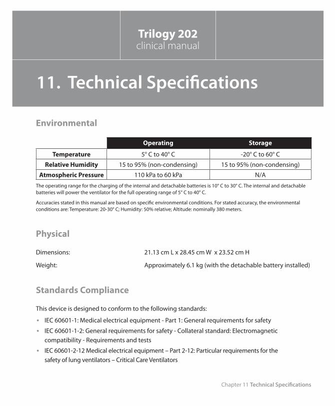
Chapter 11 Technical Specifications
151
Environmental
Operating Storage
Temperature 5° C to 40° C -20° C to 60° C
Relative Humidity 15 to 95% (non-condensing) 15 to 95% (non-condensing)
Atmospheric Pressure 110 kPa to 60 kPa N/A
The operating range for the charging of the internal and detachable batteries is 10° C to 30° C. The internal and detachable batteries will power the ventilator for the full operating range of 5° C to 40° C.
Accuracies stated in this manual are based on specific environmental conditions. For stated accuracy, the environmental conditions are: Temperature: 20-30° C; Humidity: 50% relative; Altitude: nominally 380 meters.
Physical
Dimensions: 21.13 cm L x 28.45 cm W x 23.52 cm H
Weight: Approximately 6.1 kg (with the detachable battery installed)
Standards Compliance
This device is designed to conform to the following standards:
IEC 60601-1: Medical electrical equipment - Part 1: General requirements for safety •IEC 60601-1-2: General requirements for safety - Collateral standard: Electromagnetic •compatibility - Requirements and tests
IEC 60601-2-12 Medical electrical equipment – Part 2-12: Particular requirements for the •safety of lung ventilators – Critical Care Ventilators
Trilogy 202clinical manual
11. Technical Specifications
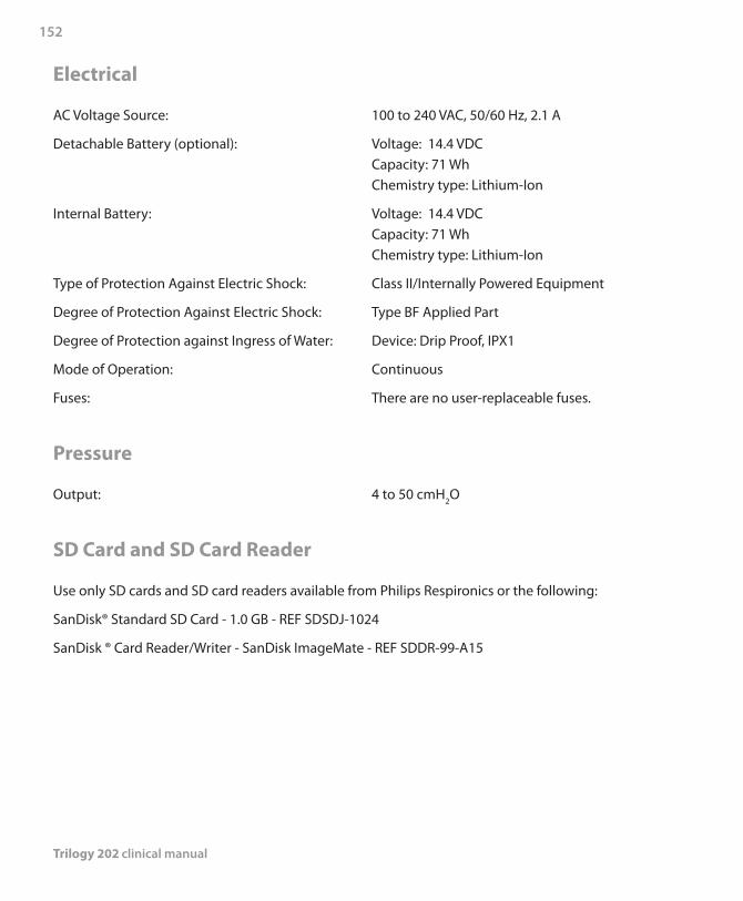
Trilogy 202 clinical manual
152
Electrical
AC Voltage Source: 100 to 240 VAC, 50/60 Hz, 2.1 A
Detachable Battery (optional): Voltage: 14.4 VDC Capacity: 71 Wh Chemistry type: Lithium-Ion
Internal Battery: Voltage: 14.4 VDC Capacity: 71 Wh Chemistry type: Lithium-Ion
Type of Protection Against Electric Shock: Class II/Internally Powered Equipment
Degree of Protection Against Electric Shock: Type BF Applied Part
Degree of Protection against Ingress of Water: Device: Drip Proof, IPX1
Mode of Operation: Continuous
Fuses: There are no user-replaceable fuses.
Pressure
Output: 4 to 50 cmH2O
SD Card and SD Card Reader
Use only SD cards and SD card readers available from Philips Respironics or the following:
SanDisk® Standard SD Card - 1.0 GB - REF SDSDJ-1024
SanDisk ® Card Reader/Writer - SanDisk ImageMate - REF SDDR-99-A15
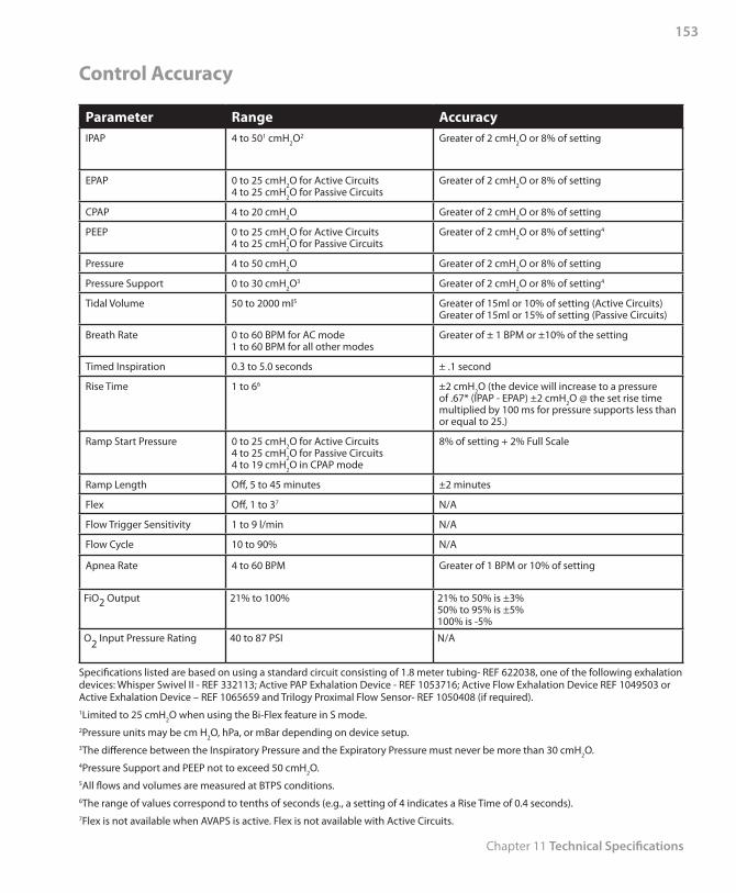
Chapter 11 Technical Specifications
153
Control Accuracy
Parameter Range AccuracyIPAP 4 to 501 cmH2O2 Greater of 2 cmH2O or 8% of setting
EPAP 0 to 25 cmH2O for Active Circuits4 to 25 cmH2O for Passive Circuits
Greater of 2 cmH2O or 8% of setting
CPAP 4 to 20 cmH2O Greater of 2 cmH2O or 8% of setting
PEEP 0 to 25 cmH2O for Active Circuits4 to 25 cmH2O for Passive Circuits
Greater of 2 cmH2O or 8% of setting4
Pressure 4 to 50 cmH2O Greater of 2 cmH2O or 8% of setting
Pressure Support 0 to 30 cmH2O3 Greater of 2 cmH2O or 8% of setting4
Tidal Volume 50 to 2000 ml5 Greater of 15ml or 10% of setting (Active Circuits)Greater of 15ml or 15% of setting (Passive Circuits)
Breath Rate 0 to 60 BPM for AC mode1 to 60 BPM for all other modes
Greater of ± 1 BPM or ±10% of the setting
Timed Inspiration 0.3 to 5.0 seconds ± .1 second
Rise Time 1 to 66 ±2 cmH2O (the device will increase to a pressure of .67* (IPAP - EPAP) ±2 cmH2O @ the set rise time multiplied by 100 ms for pressure supports less than or equal to 25.)
Ramp Start Pressure 0 to 25 cmH2O for Active Circuits4 to 25 cmH2O for Passive Circuits4 to 19 cmH2O in CPAP mode
8% of setting + 2% Full Scale
Ramp Length Off, 5 to 45 minutes ±2 minutes
Flex Off, 1 to 37 N/A
Flow Trigger Sensitivity 1 to 9 l/min N/A
Flow Cycle 10 to 90% N/A
Apnea Rate 4 to 60 BPM Greater of 1 BPM or 10% of setting
FiO2 Output 21% to 100% 21% to 50% is ±3%50% to 95% is ±5%100% is -5%
O2 Input Pressure Rating 40 to 87 PSI N/A
Specifications listed are based on using a standard circuit consisting of 1.8 meter tubing- REF 622038, one of the following exhalation devices: Whisper Swivel II - REF 332113; Active PAP Exhalation Device - REF 1053716; Active Flow Exhalation Device REF 1049503 or Active Exhalation Device – REF 1065659 and Trilogy Proximal Flow Sensor- REF 1050408 (if required).1Limited to 25 cmH2O when using the Bi-Flex feature in S mode.2Pressure units may be cm H2O, hPa, or mBar depending on device setup.3The difference between the Inspiratory Pressure and the Expiratory Pressure must never be more than 30 cmH2O.4Pressure Support and PEEP not to exceed 50 cmH2O.5All flows and volumes are measured at BTPS conditions.6The range of values correspond to tenths of seconds (e.g., a setting of 4 indicates a Rise Time of 0.4 seconds).7Flex is not available when AVAPS is active. Flex is not available with Active Circuits.
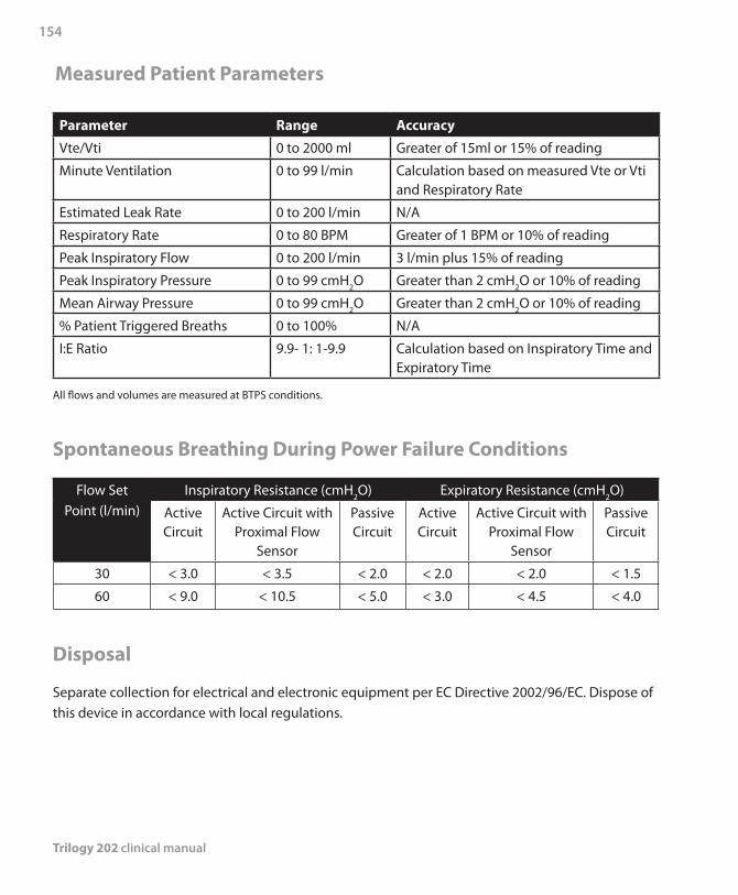
Trilogy 202 clinical manual
154
Measured Patient Parameters
Parameter Range Accuracy
Vte/Vti 0 to 2000 ml Greater of 15ml or 15% of reading
Minute Ventilation 0 to 99 l/min Calculation based on measured Vte or Vti and Respiratory Rate
Estimated Leak Rate 0 to 200 l/min N/A
Respiratory Rate 0 to 80 BPM Greater of 1 BPM or 10% of reading
Peak Inspiratory Flow 0 to 200 l/min 3 l/min plus 15% of reading
Peak Inspiratory Pressure 0 to 99 cmH2O Greater than 2 cmH2O or 10% of reading
Mean Airway Pressure 0 to 99 cmH2O Greater than 2 cmH2O or 10% of reading
% Patient Triggered Breaths 0 to 100% N/A
I:E Ratio 9.9- 1: 1-9.9 Calculation based on Inspiratory Time and Expiratory Time
All flows and volumes are measured at BTPS conditions.
Spontaneous Breathing During Power Failure Conditions
Flow Set Point (l/min)
Inspiratory Resistance (cmH2O) Expiratory Resistance (cmH2O)
Active Circuit
Active Circuit withProximal Flow
Sensor
Passive Circuit
Active Circuit
Active Circuit withProximal Flow
Sensor
Passive Circuit
30 < 3.0 < 3.5 < 2.0 < 2.0 < 2.0 < 1.5
60 < 9.0 < 10.5 < 5.0 < 3.0 < 4.5 < 4.0
Disposal
Separate collection for electrical and electronic equipment per EC Directive 2002/96/EC. Dispose of this device in accordance with local regulations.
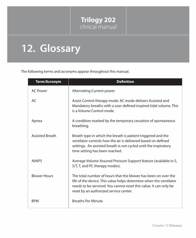
Chapter 12 Glossary
155
The following terms and acronyms appear throughout this manual.
Term/Acronym Definition
AC Power Alternating Current power
AC Assist Control therapy mode; AC mode delivers Assisted and Mandatory breaths with a user-defined inspired tidal volume. This is a Volume Control mode.
Apnea A condition marked by the temporary cessation of spontaneous breathing.
Assisted Breath Breath type in which the breath is patient-triggered and the ventilator controls how the air is delivered based on defined settings. An assisted breath is not cycled until the inspiratory time setting has been reached.
AVAPS Average Volume Assured Pressure Support feature (available in S, S/T, T, and PC therapy modes).
Blower Hours The total number of hours that the blower has been on over the life of the device. This value helps determine when the ventilator needs to be serviced. You cannot reset this value. It can only be reset by an authorized service center.
BPM Breaths Per Minute
Trilogy 202clinical manual
12. Glossary
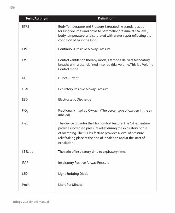
Trilogy 202 clinical manual
156
Term/Acronym Definition
BTPS Body Temperature and Pressure Saturated; A standardization for lung volumes and flows to barometric pressure at sea level, body temperature, and saturated with water vapor reflecting the condition of air in the lung.
CPAP Continuous Positive Airway Pressure
CV Control Ventilation therapy mode; CV mode delivers Mandatory breaths with a user-defined inspired tidal volume. This is a Volume Control mode.
DC Direct Current
EPAP Expiratory Positive Airway Pressure
ESD Electrostatic Discharge
FiO2 Fractionally Inspired Oxygen (The percentage of oxygen in the air inhaled)
Flex The device provides the Flex comfort feature. The C-Flex feature provides increased pressure relief during the expiratory phase of breathing. The Bi-Flex feature provides a level of pressure relief taking place at the end of inhalation and at the start of exhalation.
I:E Ratio The ratio of inspiratory time to expiratory time.
IPAP Inspiratory Positive Airway Pressure
LED Light Emitting Diode
l/min Liters Per Minute
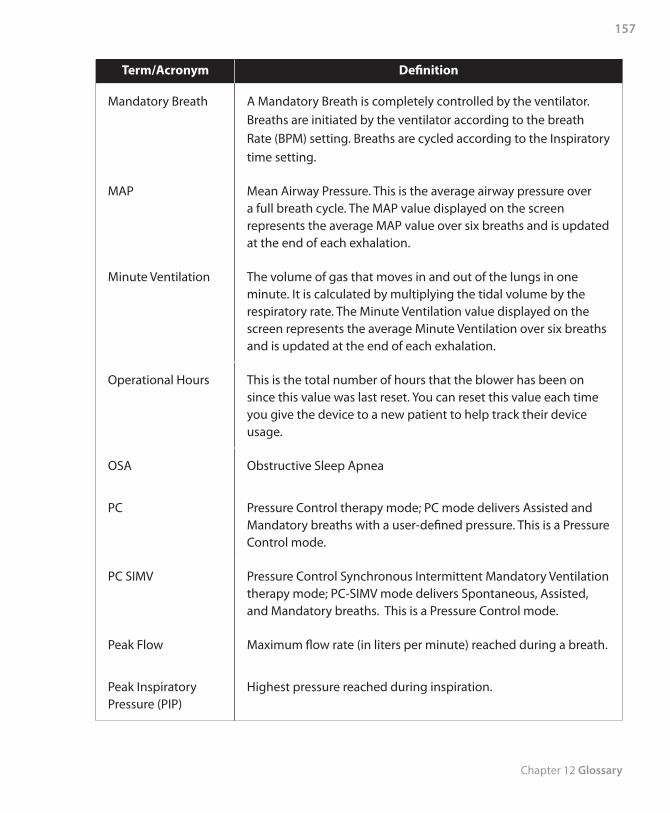
Chapter 12 Glossary
157
Term/Acronym Definition
Mandatory Breath A Mandatory Breath is completely controlled by the ventilator. Breaths are initiated by the ventilator according to the breath Rate (BPM) setting. Breaths are cycled according to the Inspiratory time setting.
MAP Mean Airway Pressure. This is the average airway pressure over a full breath cycle. The MAP value displayed on the screen represents the average MAP value over six breaths and is updated at the end of each exhalation.
Minute Ventilation The volume of gas that moves in and out of the lungs in one minute. It is calculated by multiplying the tidal volume by the respiratory rate. The Minute Ventilation value displayed on the screen represents the average Minute Ventilation over six breaths and is updated at the end of each exhalation.
Operational Hours This is the total number of hours that the blower has been on since this value was last reset. You can reset this value each time you give the device to a new patient to help track their device usage.
OSA Obstructive Sleep Apnea
PC Pressure Control therapy mode; PC mode delivers Assisted and Mandatory breaths with a user-defined pressure. This is a Pressure Control mode.
PC SIMV Pressure Control Synchronous Intermittent Mandatory Ventilation therapy mode; PC-SIMV mode delivers Spontaneous, Assisted, and Mandatory breaths. This is a Pressure Control mode.
Peak Flow Maximum flow rate (in liters per minute) reached during a breath.
Peak Inspiratory Pressure (PIP)
Highest pressure reached during inspiration.
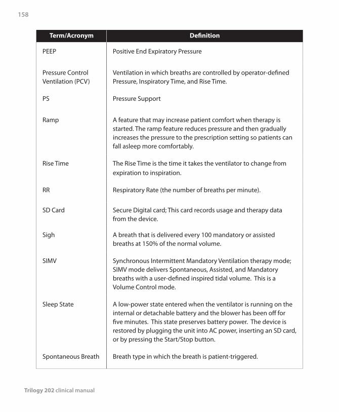
Trilogy 202 clinical manual
158
Term/Acronym Definition
PEEP Positive End Expiratory Pressure
Pressure Control Ventilation (PCV)
Ventilation in which breaths are controlled by operator-defined Pressure, Inspiratory Time, and Rise Time.
PS Pressure Support
Ramp A feature that may increase patient comfort when therapy is started. The ramp feature reduces pressure and then gradually increases the pressure to the prescription setting so patients can fall asleep more comfortably.
Rise Time The Rise Time is the time it takes the ventilator to change from expiration to inspiration.
RR Respiratory Rate (the number of breaths per minute).
SD Card Secure Digital card; This card records usage and therapy data from the device.
Sigh A breath that is delivered every 100 mandatory or assisted breaths at 150% of the normal volume.
SIMV Synchronous Intermittent Mandatory Ventilation therapy mode; SIMV mode delivers Spontaneous, Assisted, and Mandatory breaths with a user-defined inspired tidal volume. This is a Volume Control mode.
Sleep State A low-power state entered when the ventilator is running on the internal or detachable battery and the blower has been off for five minutes. This state preserves battery power. The device is restored by plugging the unit into AC power, inserting an SD card, or by pressing the Start/Stop button.
Spontaneous Breath Breath type in which the breath is patient-triggered.
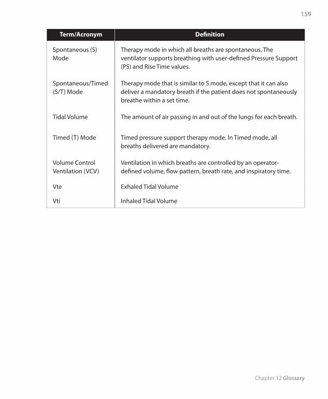
Chapter 12 Glossary
159
Term/Acronym Definition
Spontaneous (S) Mode
Therapy mode in which all breaths are spontaneous. The ventilator supports breathing with user-defined Pressure Support (PS) and Rise Time values.
Spontaneous/Timed (S/T) Mode
Therapy mode that is similar to S mode, except that it can also deliver a mandatory breath if the patient does not spontaneously breathe within a set time.
Tidal Volume The amount of air passing in and out of the lungs for each breath.
Timed (T) Mode Timed pressure support therapy mode. In Timed mode, all breaths delivered are mandatory.
Volume Control Ventilation (VCV)
Ventilation in which breaths are controlled by an operator-defined volume, flow pattern, breath rate, and inspiratory time.
Vte Exhaled Tidal Volume
Vti Inhaled Tidal Volume

Trilogy 202 clinical manual
160
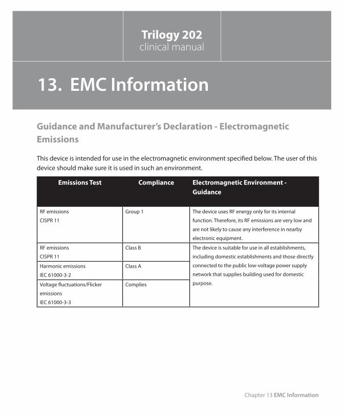
Chapter 13 EMC Information
161
Guidance and Manufacturer’s Declaration - Electromagnetic Emissions
This device is intended for use in the electromagnetic environment specified below. The user of this device should make sure it is used in such an environment.
Emissions Test Compliance Electromagnetic Environment - Guidance
RF emissions
CISPR 11
Group 1 The device uses RF energy only for its internal
function. Therefore, its RF emissions are very low and
are not likely to cause any interference in nearby
electronic equipment.
RF emissions
CISPR 11
Class B The device is suitable for use in all establishments,
including domestic establishments and those directly
connected to the public low-voltage power supply
network that supplies building used for domestic
purpose.
Harmonic emissions
IEC 61000-3-2
Class A
Voltage fluctuations/Flicker
emissions
IEC 61000-3-3
Complies
Trilogy 202clinical manual
13. EMC Information
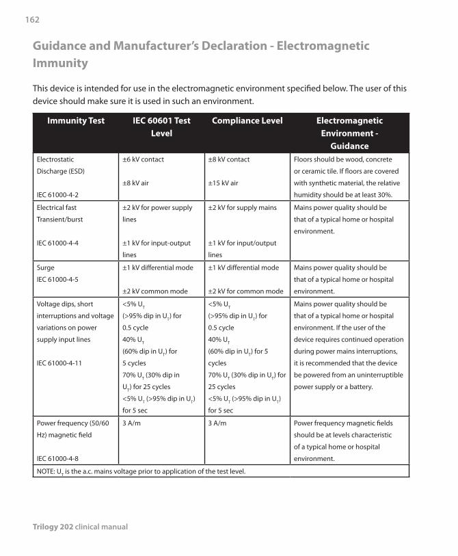
Trilogy 202 clinical manual
162
Guidance and Manufacturer’s Declaration - Electromagnetic Immunity
This device is intended for use in the electromagnetic environment specified below. The user of this device should make sure it is used in such an environment.
Immunity Test IEC 60601 Test Level
Compliance Level Electromagnetic Environment -
GuidanceElectrostatic
Discharge (ESD)
IEC 61000-4-2
±6 kV contact
±8 kV air
±8 kV contact
±15 kV air
Floors should be wood, concrete
or ceramic tile. If floors are covered
with synthetic material, the relative
humidity should be at least 30%.
Electrical fast
Transient/burst
IEC 61000-4-4
±2 kV for power supply
lines
±1 kV for input-output
lines
±2 kV for supply mains
±1 kV for input/output
lines
Mains power quality should be
that of a typical home or hospital
environment.
Surge
IEC 61000-4-5
±1 kV differential mode
±2 kV common mode
±1 kV differential mode
±2 kV for common mode
Mains power quality should be
that of a typical home or hospital
environment.
Voltage dips, short
interruptions and voltage
variations on power
supply input lines
IEC 61000-4-11
<5% UT
(>95% dip in UT) for
0.5 cycle
40% UT
(60% dip in UT) for
5 cycles
70% UT (30% dip in
UT) for 25 cycles
<5% UT (>95% dip in UT)
for 5 sec
<5% UT
(>95% dip in UT) for
0.5 cycle
40% UT
(60% dip in UT) for 5
cycles
70% UT (30% dip in UT) for
25 cycles
<5% UT (>95% dip in UT)
for 5 sec
Mains power quality should be
that of a typical home or hospital
environment. If the user of the
device requires continued operation
during power mains interruptions,
it is recommended that the device
be powered from an uninterruptible
power supply or a battery.
Power frequency (50/60
Hz) magnetic field
IEC 61000-4-8
3 A/m 3 A/m Power frequency magnetic fields
should be at levels characteristic
of a typical home or hospital
environment.
NOTE: UT is the a.c. mains voltage prior to application of the test level.
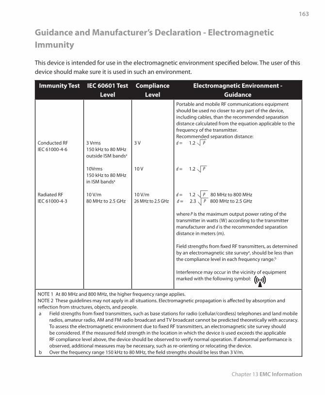
Chapter 13 EMC Information
163
Guidance and Manufacturer’s Declaration - Electromagnetic Immunity
This device is intended for use in the electromagnetic environment specified below. The user of this device should make sure it is used in such an environment.
Immunity Test IEC 60601 Test Level
Compliance Level
Electromagnetic Environment -Guidance
Conducted RFIEC 61000-4-6
Radiated RFIEC 61000-4-3
3 Vrms150 kHz to 80 MHz outside ISM bandsa
10Vrms150 kHz to 80 MHz in ISM bandsa
10 V/m80 MHz to 2.5 GHz
3 V
10 V
10 V/m26 MHz to 2.5 GHz
Portable and mobile RF communications equipment should be used no closer to any part of the device, including cables, than the recommended separation distance calculated from the equation applicable to the frequency of the transmitter.Recommended separation distance:d = 1.2 P
d = 1.2 P
d = 1.2 P 80 MHz to 800 MHz d = 2.3 P 800 MHz to 2.5 GHz
where P is the maximum output power rating of the transmitter in watts (W) according to the transmitter manufacturer and d is the recommended separation distance in meters (m).
Field strengths from fixed RF transmitters, as determined by an electromagnetic site surveya, should be less than the compliance level in each frequency range.b
Interference may occur in the vicinity of equipment marked with the following symbol:
NOTE 1 At 80 MHz and 800 MHz, the higher frequency range applies.NOTE 2 These guidelines may not apply in all situations. Electromagnetic propagation is affected by absorption and reflection from structures, objects, and people. a Field strengths from fixed transmitters, such as base stations for radio (cellular/cordless) telephones and land mobile
radios, amateur radio, AM and FM radio broadcast and TV broadcast cannot be predicted theoretically with accuracy. To assess the electromagnetic environment due to fixed RF transmitters, an electromagnetic site survey should be considered. If the measured field strength in the location in which the device is used exceeds the applicable RF compliance level above, the device should be observed to verify normal operation. If abnormal performance is observed, additional measures may be necessary, such as re-orienting or relocating the device.
b Over the frequency range 150 kHz to 80 MHz, the field strengths should be less than 3 V/m.
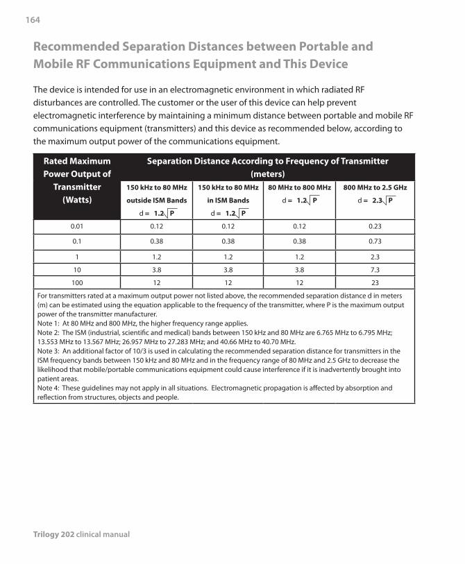
Trilogy 202 clinical manual
164
Recommended Separation Distances between Portable and Mobile RF Communications Equipment and This Device
The device is intended for use in an electromagnetic environment in which radiated RF disturbances are controlled. The customer or the user of this device can help prevent electromagnetic interference by maintaining a minimum distance between portable and mobile RF communications equipment (transmitters) and this device as recommended below, according to the maximum output power of the communications equipment.
Rated Maximum Power Output of
Transmitter(Watts)
Separation Distance According to Frequency of Transmitter (meters)
150 kHz to 80 MHz
outside ISM Bands
d = 1.2 P
150 kHz to 80 MHz
in ISM Bands
d = 1.2 P
80 MHz to 800 MHz
d = 1.2 P
800 MHz to 2.5 GHz
d = 2.3 P
0.01 0.12 0.12 0.12 0.23
0.1 0.38 0.38 0.38 0.73
1 1.2 1.2 1.2 2.3
10 3.8 3.8 3.8 7.3
100 12 12 12 23
For transmitters rated at a maximum output power not listed above, the recommended separation distance d in meters (m) can be estimated using the equation applicable to the frequency of the transmitter, where P is the maximum output power of the transmitter manufacturer.Note 1: At 80 MHz and 800 MHz, the higher frequency range applies.Note 2: The ISM (industrial, scientific and medical) bands between 150 kHz and 80 MHz are 6.765 MHz to 6.795 MHz; 13.553 MHz to 13.567 MHz; 26.957 MHz to 27.283 MHz; and 40.66 MHz to 40.70 MHz.Note 3: An additional factor of 10/3 is used in calculating the recommended separation distance for transmitters in the ISM frequency bands between 150 kHz and 80 MHz and in the frequency range of 80 MHz and 2.5 GHz to decrease the likelihood that mobile/portable communications equipment could cause interference if it is inadvertently brought into patient areas.Note 4: These guidelines may not apply in all situations. Electromagnetic propagation is affected by absorption and reflection from structures, objects and people.
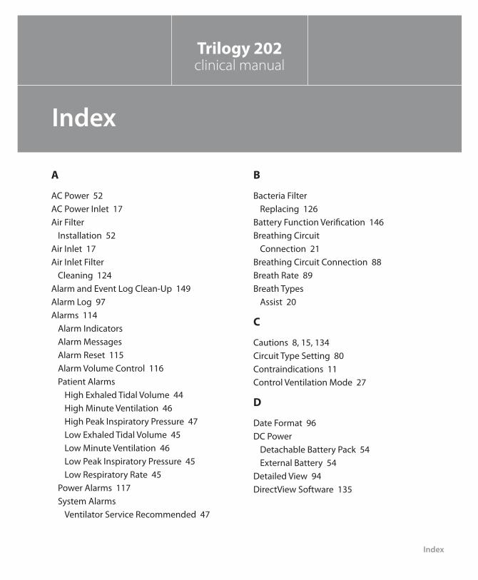
Index
165
Trilogy 202clinical manual
Index
A
AC Power 52AC Power Inlet 17Air Filter
Installation 52Air Inlet 17Air Inlet Filter
Cleaning 124Alarm and Event Log Clean-Up 149Alarm Log 97Alarms 114
Alarm Indicators Alarm Messages Alarm Reset 115Alarm Volume Control 116Patient Alarms
High Exhaled Tidal Volume 44High Minute Ventilation 46High Peak Inspiratory Pressure 47Low Exhaled Tidal Volume 45Low Minute Ventilation 46Low Peak Inspiratory Pressure 45Low Respiratory Rate 45
Power Alarms 117System Alarms
Ventilator Service Recommended 47
B
Bacteria FilterReplacing 126
Battery Function Verification 146Breathing Circuit
Connection 21Breathing Circuit Connection 88Breath Rate 89Breath Types
Assist 20
C
Cautions 8, 15, 134Circuit Type Setting 80Contraindications 11Control Ventilation Mode 27
D
Date Format 96DC Power
Detachable Battery Pack 54External Battery 54
Detailed View 94DirectView Software 135
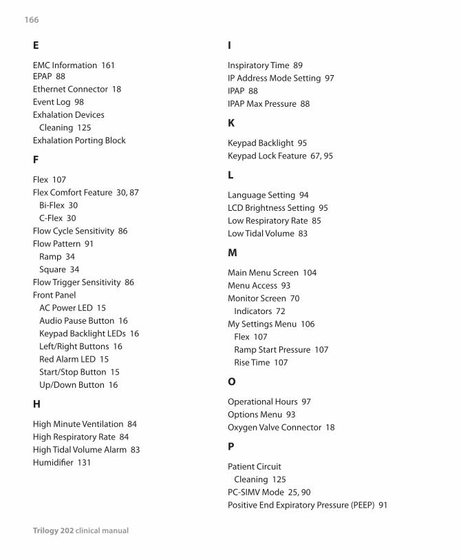
Trilogy 202 clinical manual
166
E
EMC Information 161EPAP 88Ethernet Connector 18Event Log 98Exhalation Devices
Cleaning 125Exhalation Porting Block
F
Flex 107Flex Comfort Feature 30, 87
Bi-Flex 30C-Flex 30
Flow Cycle Sensitivity 86Flow Pattern 91
Ramp 34Square 34
Flow Trigger Sensitivity 86Front Panel
AC Power LED 15Audio Pause Button 16Keypad Backlight LEDs 16Left/Right Buttons 16Red Alarm LED 15Start/Stop Button 15Up/Down Button 16
H
High Minute Ventilation 84High Respiratory Rate 84High Tidal Volume Alarm 83Humidifier 131
I
Inspiratory Time 89IP Address Mode Setting 97IPAP 88IPAP Max Pressure 88
K
Keypad Backlight 95Keypad Lock Feature 67, 95
L
Language Setting 94LCD Brightness Setting 95Low Respiratory Rate 85Low Tidal Volume 83
M
Main Menu Screen 104Menu Access 93Monitor Screen 70
Indicators 72My Settings Menu 106
Flex 107Ramp Start Pressure 107Rise Time 107
O
Operational Hours 97Options Menu 93Oxygen Valve Connector 18
P
Patient CircuitCleaning 125
PC-SIMV Mode 25, 90Positive End Expiratory Pressure (PEEP) 91
Index
167
Pressure Control Mode 24Pressure Control Ventilation 89Pressure Setting 90Pressure Support 90
R
Ramp Feature 31Ramp Length 86Ramp Start Pressure 87, 107Remote Alarm 65, 114Remote Alarm Connector 18Rise Time 32, 89, 107
S
Screen Saver 96Secondary Prescription Setting 105Secure Digital (SD) Card 17, 134Sensitivity 36
Digital Auto-Trak SensitivityAuto-Trak Sensitivity 37Leak Tolerance 36
Flow Trigger 40Serial Connector 18Settings and Alarms Tests 138Setup Screen 69Sigh Feature 91SIMV Mode 28, 92Specifications
Control Accuracy 152Electrical 152Environmental 151Pressure 152Standards Compliance 151
T
Tidal Volume 88Timed Mode 89Time Format 96Trigger Type
Auto-Trak 86Flow Trigger 86
Troubleshooting 127
V
Volume Control Ventilation 19
W
Warnings 3Warranty 169Water Trap 64

Trilogy 202 clinical manual
168

Limited Warranty
169
Respironics, Inc. warrants that the Trilogy 202 system shall be free from defects of workmanship and materials and will perform in accordance with the product specifications for a period of two (2) years from the date of sale by Respironics, Inc. to the dealer. If the product fails to perform in accordance with the product specifications, Respironics, Inc.will repair or replace – at its option – the defective material or part. Respironics, Inc. will pay customary freight charges from Respironics, Inc. to the dealer location only. This warranty does not cover damage caused by accident, misuse, abuse, alteration, and other defects not related to material or workmanship.
Respironics, Inc. disclaims all liability for economic loss, loss of profits,overhead, or consequential damages which may be claimed to arise from any sale or use of this product. Some states do not allow the exclusion or limitation of incidental or consequential damages, so the above limitation or exclusion may not apply to you.
Accessories and replacement parts, including, but not limited to, circuits, tubing, leak devices, exhaust valves, filters and fuses, are not covered under this warranty. However, Respironics warrants that the Product’s internal and detachable battery (where supplied) will be free from defects in material and workmanship, under normal and proper use and when correctly maintained in accordance with applicable instructions, for a period of 90 days from the date of shipment by Respironics to the original purchaser. This warranty does not apply to batteries that are dropped, misused, altered or otherwise damaged after they are shipped.
This warranty is given in lieu of all other express warranties. In addition, any implied warranties – including any warranty of merchantability or fitness for the particular purpose – are limited to two years. Some states do not allow limitations on how long an implied warranty lasts, so the above limitation may not apply to you. This warranty gives you specific legal rights, and you may also have other rights which vary from state to state.
Trilogy 202clinical manual
Limited Warranty

Trilogy 202 clinical manual
170
To exercise your rights under this warranty, contact your local authorized Respironics, Inc. dealer or contact Respironics, Inc. at:
1001 Murry Ridge LaneMurrysville, Pennsylvania 15668-8550
1-724-387-4000
Deutschland Gewerbestrasse 17
82211 Herrsching Germany+49 8152 93060