Embed Size (px)
Citation preview
3DR Support
Contact 3DR Support for questions and technical help.
online: 3dr.com/support email: [email protected] call: +1 (858) 225-1414 (direct) +1 (855) 982-2898 (toll free in the US and Canada)
Support line hours:Mon-Fri 8 am to 5 pm PST
3D Robotics (3DR)1608 4th Street, Suite 410 Berkeley, CA 94710Tel. +1 (858) 225-14143dr.com
Solo User Manual V7© 2015 3D Robotics Inc.Solo is a trademark of 3D Robotics, Inc.
GoPro, HERO, the GoPro logo, and the GoPro Be a HERO logo are trademarks or registered trademarks of GoPro, Inc.
Contents
1 Introduction 11.1 System Overview 11.2 Aircraft Overview 21.3 Controller Overview 31.4 Operating Parameters 41.5 Autopilot 51.6 Propulsion 51.7 LED Meanings 5
2 Setup 62.1 In the Box 62.2 Battery 62.3 Controller 82.4 Propellers 92.5 Camera 92.6 Mobile App 11
3 The Solo Gimbal 153.1 In the Box 153.2 Gimbal Installation 153.3 Gimbal Operation 21
4 Safety 244.1 Location 244.2 Environmental Awareness 244.3 Visual Line of Sight 244.4 Flight School 254.5 Propellers 254.6 GPS 254.7 Home Position 254.8 Altitude Limit 264.9 Emergency Procedures 264.10 Flight Battery 274.11 Controller 274.12 Antenna Configuration 28
5 First Flight 295.1 Preflight Checklist 295.2 Takeoff 295.3 Landing 305.4 Return Home 315.5 In-Flight Data 325.6 Joystick Control 335.7 App Interface Overview 36
6 Smart Shots 376.1 Selfie 376.2 Cable Cam 396.3 Orbit 406.4 Follow 41
7 Alerts 437.1 Preflight Errors 437.2 In-Flight Errors 44
8 Advanced Settings 478.1 Advanced Flight Modes 478.2 Enabling Advanced Flight Modes 48
8.3 Accessing Advanced Flight Modes 488.4 Home Position Safety 488.5 Performance Adjustment 498.6 Units 498.7 Maximum Altitude Adjustment 49
9 Support 50
10 Maintenance 5010.1 Controller Battery Replacement 5010.2 Calibrations 5110.3 Pairing the Controller 5210.4 Legs 5310.5 Battery Tray 5610.6 Motor Mods 5710.7 Factory Reset 59
11 Appendix 6211.1 Specifications 6211.2 Warranty 6311.3 Regulatory Compliance 63
FiguresFigure 1.1.3.1: Solo System Context Diagram 1Figure 1.2.4.1: Solo Overview 2Figure 1.3.10.1: Controller Overview 4Figure 1.4.1: Solo Operating Parameters 4Figure 1.6.1: Solo Motor Order 5Figure 2.1.1: Solo Parts 6Figure 2.2.1.1: Charing the Solo Smart Battery 7Figure 2.2.2.1: Powering Solo 7Figure 2.3.1.1: Controller Charging 8Figure 2.3.2.1: Power On Controller 8Figure 2.4.1.1: Attach Propellers 9Figure 2.5.1.1: Attach Camera 10Figure 2.5.2.1: Camera Configuration Process 10Figure 2.6.2.1: Connect to Solo Link 11Figure 2.6.3.1: App - Settings Menu 11Figure 2.6.3.2: App - Wi-Fi Settings 12Figure 2.6.4.1: Controller Preflight Update Prompt 12Figure 2.6.4.2: App - Software Update 12Figure 2.6.4.3: App - Connecting Instructions 12Figure 2.6.4.4: App - Instructions List 13Figure 2.6.4.5: App - Download Update 13Figure 2.6.4.6: App - Start Update 13Figure 2.6.4.7: Controller - Updating 13Figure 2.6.4.8: App - Update Disconnection Confirmation 13Figure 2.6.4.9: Controller Update Complete Displays 14Figure 2.6.4.10: Controller - Waiting for Solo 14Figure 2.6.4.11: App - Update Success 14Figure 2.6.5.1: App - Viewing Video 14Figure 3.1.1: Solo Gimbal Parts 15Figure 3.2.1.1: The Frame Removal 16Figure 3.2.2.1: Connecting cables 16Figure 3.2.3.1: Positioning the Gimbal Cable 17Figure 3.2.3.2: Positioning the HDMI Cable 17Figure 3.2.4.1: Mounting the Gimbal 18Figure 3.2.5.1: HDMI Plug Positioning 18Figure 3.2.5.2: Attach GoPro 19Figure 3.2.5.3: Fasten Camera 19Figure 3.2.6.1: GoPro Weight Balancing 19Figure 3.2.7.1: Adding the Sunshade 20Figure 3.2.9.1: Camera Configuration Process 21Figure 3.3.1.1: Gimbal Controls 21Figure 3.3.2.1: LED Gimbal Signal 22Figure 4.4.1: App Flight School 25Figure 4.9.5.1: Controller - Motor Shutoff 27Figure 4.12.1: Controller Antenna Orientation 28Figure 5.2.1.1: Controller - Start Motors Prompt 29Figure 5.2.2.1: Controller - Takeoff Prompts 30Figure 5.3.1: Controller - User-Initiated Landing 30Figure 5.4.1: Return to Home Button 31Figure 5.4.2: Return Home Below 15 m 31Figure 5.4.3: Return Home Above 15m 31Figure 5.5.1: Controller - In-Flight Data 32Figure 5.6.1: Controller Left Joystick 33Figure 5.6.2: Throttle Joystick Behaviors 33Figure 5.6.3: Yaw Joystick Behavior 34Figure 5.6.4: Controller Right Joystick Controls 34Figure 5.6.5: Pitch Joystick Controls 35Figure 5.6.6: Roll Joystick Controls 35Figure 5.7.1: App - Main Interface 36
Figure 5.7.2.1: App - Shot List 36Figure 6.1.1: Selfie Path and Settings 37Figure 6.1.1.1: App - Selfie Activation 37Figure 6.1.2.1: App - Selfie Control 38Figure 6.1.2.2: Controller - Selfie Control 38Figure 6.1.3.1: App - Selfie Settings 38Figure 6.2.1.1: App - Cable Cam Setup 39Figure 6.2.2.1: App - Cable Cam Controls 39Figure 6.2.2.2: Controller - Cable Cam Controls 39Figure 6.2.3.1: App - Cable Cam Settings 40Figure 6.3.1.1: App - Orbit Setup 40Figure 6.3.2.1: App - Orbit Controls 40Figure 6.3.2.2: Orbit Controls 41Figure 6.3.3.1: App - Orbit Settings 41Figure 6.4.1.1: App - Follow Setup 42Figure 6.4.2.1: Follow Controls 42Figure 6.4.3.1: App - Follow Settings 42Figure 7.1.1.1: Controller - Calibration Alerts 43Figure 7.1.1.2: Controller - Uneven Surface Alert 43Figure 7.1.1.3: Controller - Re-Calibration Alerts 43Figure 7.1.1.4: Controller - Calibration Error Alert 44Figure 7.1.2.1: Controller - Service Alerts 44Figure 7.2.1.1: Controller - Altitude Limit Alert 44Figure 7.2.2.1: Controller - App Connection Alerts 45Figure 7.2.3.1: Controller - Controller Disconnected Alert 45Figure 7.2.3.2: Controller - Controller Signal Alerts 45Figure 7.2.4.1: Controller - GPS Signal Alerts 46Figure 7.2.5.1: Controller - Low Battery Alerts 46Figure 7.2.5.2: Controller - Critical Battery Alert 46Figure 7.2.6.1: Controller - Controller Battery Alerts 46Figure 8.2.1: App - Advanced Settings 48Figure 8.3.1: App - A and B Presets 48Figure 8.5.1: App - Performance Sliders 49Figure 8.6.1: App - Change Units 49Figure 8.7.1: App - Altitude Limit 49Figure 9.1: App - Submit Trouble Ticket 50Figure 10.1.1: Controller Battery Installation 50Figure 10.2.1.1: App - Compass Calibration Setup 51Figure 10.2.1.2: App - Compass Calibration Procedure 51Figure 10.2.2.1: App - Level Calibration 51Figure 10.3.1: Pair Button 52Figure 10.3.2: Detected Solo 52Figure 10.3.3: Solo Paired 52Figure 10.4.1: Leg Types 53Figure 10.4.1.1: Standard Leg Replacement Process 53Figure 10.4.2.1: Detaching the Antenna from the Leg 54Figure 10.4.2.2: New Leg with an Existing Antenna 54Figure 10.4.2.3: Attaching Antenna to a New Leg 54Figure 10.4.3.1: Compass Connector on Mainboard 55Figure 10.4.3.2: Insert New Leg with Compass 55Figure 10.5.1.1: GPS Cover Removal 56Figure 10.5.2.1: Battery Tray Removal 56Figure 10.5.2.2: Battery Tray Detachment 56Figure 10.6.1: LED Cover Removal 57Figure 10.6.2: Motor Pod Removal 57Figure 10.6.3: Motor Pod Disconnection 58Figure 10.6.4: Motor Pod Connection 58Figure 10.6.5: Motor Pod and LED Cover Attachment 58Figure 10.7.1: Pair Button 59Figure 10.7.2: Strobing Pairing Light 59Figure 10.7.3: Controller Reset 60Figure 10.7.4: Controller Update 60
1
1 IntroductionWe designed Solo to be the perfect aerial-video tool. It’s powerful, simple and reliable with intuitive Smart Shotsinspired by our favorite cinema pilots. With Solo, you don’t need a professional camera crew, you can get theperfect shot every time. We’re excited to share our passion with you and help you see your world from a newperspective. Join us in capturing the next evolution of creative videography
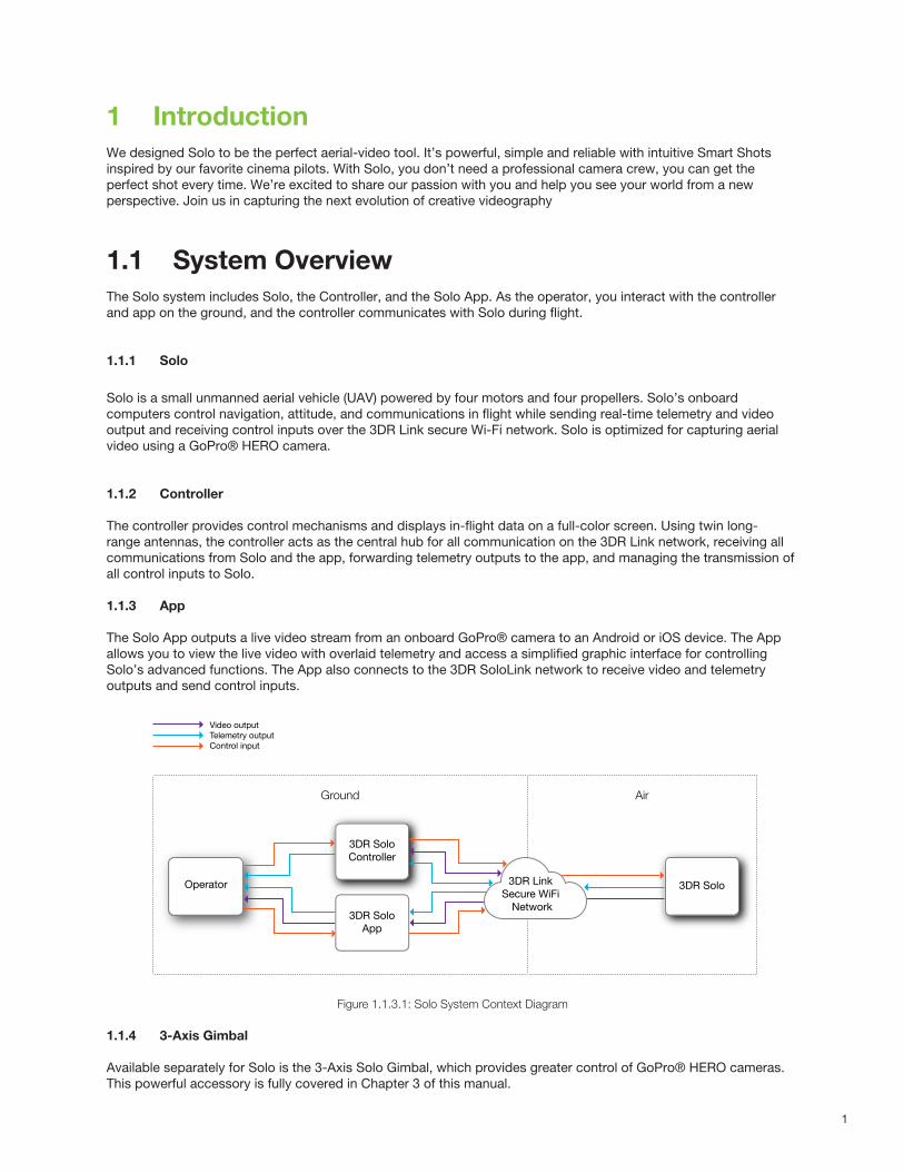
1.1 System OverviewThe Solo system includes Solo, the Controller, and the Solo App. As the operator, you interact with the controller and app on the ground, and the controller communicates with Solo during flight.
1.1.1 Solo
Solo is a small unmanned aerial vehicle (UAV) powered by four motors and four propellers. Solo’s onboard computers control navigation, attitude, and communications in flight while sending real-time telemetry and video output and receiving control inputs over the 3DR Link secure Wi-Fi network. Solo is optimized for capturing aerial video using a GoPro® HERO camera.
1.1.2 Controller
The controller provides control mechanisms and displays in-flight data on a full-color screen. Using twin long-range antennas, the controller acts as the central hub for all communication on the 3DR Link network, receiving all communications from Solo and the app, forwarding telemetry outputs to the app, and managing the transmission of all control inputs to Solo.
1.1.3 App
The Solo App outputs a live video stream from an onboard GoPro® camera to an Android or iOS device. The App allows you to view the live video with overlaid telemetry and access a simplified graphic interface for controlling Solo’s advanced functions. The App also connects to the 3DR SoloLink network to receive video and telemetry outputs and send control inputs.
Figure 1.1.3.1: Solo System Context Diagram
1.1.4 3-Axis Gimbal
Available separately for Solo is the 3-Axis Solo Gimbal, which provides greater control of GoPro® HERO cameras. This powerful accessory is fully covered in Chapter 3 of this manual.
Video outputTelemetry outputControl input
Operator
3DR SoloController
3DR Solo
3DR SoloApp
AirGround
3DR Link Secure WiFi
Network
2
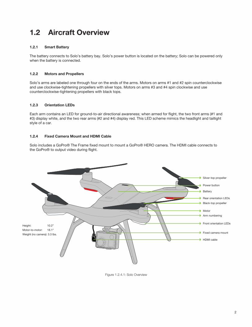
1.2 Aircraft Overview
1.2.1 Smart Battery
The battery connects to Solo’s battery bay. Solo’s power button is located on the battery; Solo can be powered onlywhen the battery is connected.
1.2.2 Motors and Propellers
Solo’s arms are labeled one through four on the ends of the arms. Motors on arms #1 and #2 spin counterclockwiseand use clockwise-tightening propellers with silver tops. Motors on arms #3 and #4 spin clockwise and usecounterclockwise-tightening propellers with black tops.
1.2.3 Orientation LEDs
Each arm contains an LED for ground-to-air directional awareness; when armed for flight, the two front arms (#1 and#3) display white, and the two rear arms (#2 and #4) display red. This LED scheme mimics the headlight and taillightstyle of a car.
1.2.4 Fixed Camera Mount and HDMI Cable
Solo includes a GoPro® The Frame fixed mount to mount a GoPro® HERO camera. The HDMI cable connects to the GoPro® to output video during flight.
Figure 1.2.4.1: Solo Overview
Silver-top propeller
Power button
Battery
Rear orientation LEDs
Black-top propeller
Motor
Arm numbering
Front orientation LEDs
Fixed camera mount
HDMI cable
Height: 10.2”
Motor-to-motor: 18.1”
Weight (no camera): 3.3 lbs.
3
1.3 Controller Overview
1.3.1 Mobile-Device Holder
Mount an Android or iOS device to run the Solo App and effortlessly integrate the App into the controller’soperational flow. A user-supplied smartphone or tablet is required to initialize Solo and use Smart Shots.
1.3.2 Joysticks
The controller’s left and right joysticks provide direct manual control of Solo and physical control mechanisms foruse with Smart Shots.
1.3.3 Screen
The controller’s full-color screen provides live in-flight data and prompts for certain Solo functions.
1.3.4 Power Button
Press the power button once to check the controller’s battery level. Hold the power button until you see the controller startup screen to power on the controller.
1.3.5 Fly Button
The Fly button lets you control Solo’s main flight functions: starting motors, takeoff, land, and activating GPS flight.
1.3.6 Return Home
The Return Home button allows you to end your flight automatically at any point by returning Solo to its originallaunch point and landing.
1.3.7 Pause Button
The Pause button is Solo’s emergency air brake. Press Pause to stop Solo and hover in place at any time.
1.3.8 Option Buttons
The A and B buttons change functionality based on where you are in the operational flow. The screen shows thecurrently assigned functions of A and B at all times. You can program A and B to specific functions using the App.By default, the A button is assigned to Cable Cam and the B button is assigned to Orbit.
1.3.9 Antennas
The controller’s long-range dipole antennas communicate with Solo during flight. See Section 4.12 for proper antenna configuration.
1.3.10 Gimbal Controls
Use the paddle, buttons, and dial on the top of the controller are used to control the Solo Gimbal. You can also use them in some Smart Shots.
4
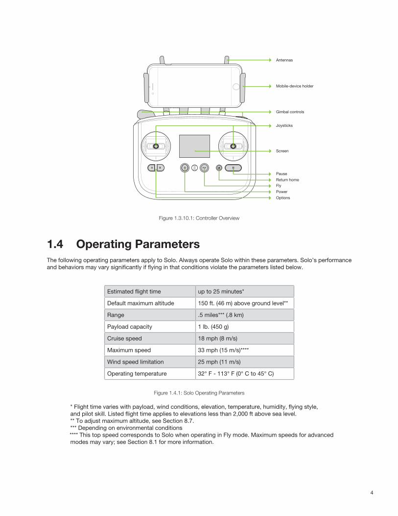
Figure 1.3.10.1: Controller Overview
1.4 Operating ParametersThe following operating parameters apply to Solo. Always operate Solo within these parameters. Solo’s performanceand behaviors may vary significantly if flying in that conditions violate the parameters listed below.
Figure 1.4.1: Solo Operating Parameters
* Flight time varies with payload, wind conditions, elevation, temperature, humidity, flying style, and pilot skill. Listed flight time applies to elevations less than 2,000 ft above sea level. ** To adjust maximum altitude, see Section 8.7. *** Depending on environmental conditions **** This top speed corresponds to Solo when operating in Fly mode. Maximum speeds for advanced modes may vary; see Section 8.1 for more information.
Antennas
Mobile-device holder
Gimbal controls
Joysticks
Screen
Pause
Return homeFly
Power
Options
Estimated flight time up to 25 minutes*
Default maximum altitude 150 ft. (46 m) above ground level**
Range .5 miles*** (.8 km)
Payload capacity 1 lb. (450 g)
Cruise speed 18 mph (8 m/s)
Maximum speed 33 mph (15 m/s)****
Wind speed limitation 25 mph (11 m/s)
Operating temperature 32° F - 113° F (0° C to 45° C)

5
1.5 AutopilotSolo uses a Pixhawk 2 autopilot running ArduPilot Copter software. ArduPilot is open-source flight control based onthe MAVlink communication protocol. Pixhawk 2 runs an ARM Cortex-M4 STM32F427 processor with 2 MB of flashmemory and 256 KB of RAM. Combined with an array of CAN, I2C, SPI, PWM, and UART interfaces, Pixhawk 2uses a suite of onboard sensors to calculate Solo’s orientation and motion in flight. This data is input into ArduPilot’sinertial navigation and position-estimation algorithms and combined with control inputs to send commands to Solo’spropulsion system.
1.6 PropulsionSolo uses four brushless 880 Kv motors and four self-tightening propellers for propulsion. For control andaerodynamic efficiency, two motors spin clockwise and two motors spin counterclockwise. Navigation in the air isachieved by mixing propulsion of the four motors to actuate flight control along the roll, pitch, and yaw axes.
Each of the four motors is numbered by the marking on the arm. These numbers correspond to the autopilotcalculations for these commands and are used for indicating motor replacement procedures. Each motor iscontrolled by an ESC (Electronic Speed Controller) that regulates the rotation of the motors to achieve the speedcommanded by the autopilot.
Figure 1.6.1: Solo Motor Order
1.7 LED MeaningsSolo’s four LEDs indicate its status during startup and in flight.
• Solid white (front) and red (back): Ready to fly, standard flight configuration• Pulsing white (front) and red (back): Solo is flying under autopilot control• Flashing red alternating front and back: Controller signal lost• Flashing rainbow: Update in progress• Solid green, then turning off one-by-one: Startup successful• Solid green without turning off automatically: Startup unsuccessful, please restart Solo
03 01
02 04
6
2 SetupThis section covers everything you need to set up Solo out of the box.
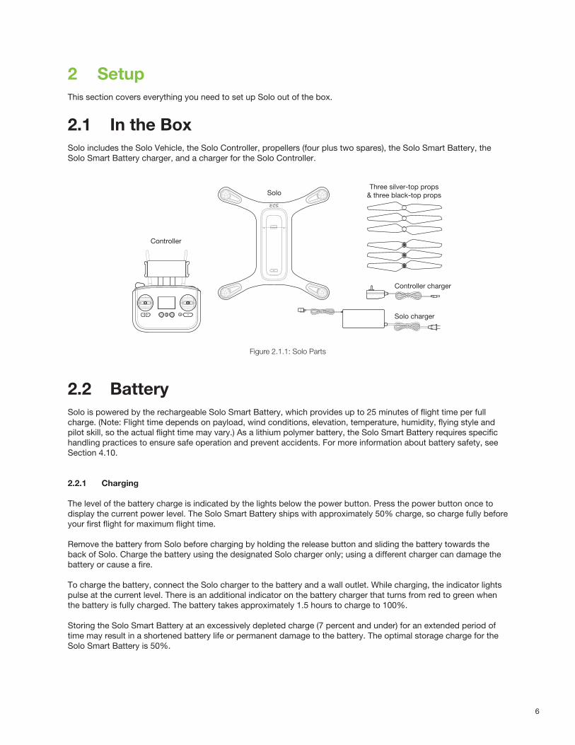
2.1 In the BoxSolo includes the Solo Vehicle, the Solo Controller, propellers (four plus two spares), the Solo Smart Battery, the Solo Smart Battery charger, and a charger for the Solo Controller.
Figure 2.1.1: Solo Parts
2.2 BatterySolo is powered by the rechargeable Solo Smart Battery, which provides up to 25 minutes of flight time per full charge. (Note: Flight time depends on payload, wind conditions, elevation, temperature, humidity, flying style and pilot skill, so the actual flight time may vary.) As a lithium polymer battery, the Solo Smart Battery requires specific handling practices to ensure safe operation and prevent accidents. For more information about battery safety, see Section 4.10.
2.2.1 Charging
The level of the battery charge is indicated by the lights below the power button. Press the power button once todisplay the current power level. The Solo Smart Battery ships with approximately 50% charge, so charge fully beforeyour first flight for maximum flight time.
Remove the battery from Solo before charging by holding the release button and sliding the battery towards theback of Solo. Charge the battery using the designated Solo charger only; using a different charger can damage thebattery or cause a fire.
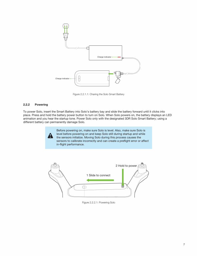
To charge the battery, connect the Solo charger to the battery and a wall outlet. While charging, the indicator lightspulse at the current level. There is an additional indicator on the battery charger that turns from red to green whenthe battery is fully charged. The battery takes approximately 1.5 hours to charge to 100%.
Storing the Solo Smart Battery at an excessively depleted charge (7 percent and under) for an extended period oftime may result in a shortened battery life or permanent damage to the battery. The optimal storage charge for theSolo Smart Battery is 50%.
SoloThree silver-top props
& three black-top props
Controller
Solo charger
Controller charger
7
Figure 2.2.1.1: Charing the Solo Smart Battery
2.2.2 Powering
To power Solo, insert the Smart Battery into Solo’s battery bay and slide the battery forward until it clicks into place. Press and hold the battery power button to turn on Solo. When Solo powers on, the battery displays an LED animation and you hear the startup tone. Power Solo only with the designated 3DR Solo Smart Battery; using a different battery can permanently damage Solo.
Figure 2.2.2.1: Powering Solo
Charge indicator
Charge indicator
Before powering on, make sure Solo is level. Also, make sure Solo is level before powering on and keep Solo still during startup and while the sensors initialize. Moving Solo during this process causes the sensors to calibrate incorrectly and can create a preflight error or affect in-flight performance.
1 Slide to connect
2 Hold to power
8
2.3 ControllerThe Solo Controller includes a pre-installed rechargeable lithium ion (Li-ion) battery.
2.3.1 Charging
Charge the controller using the designated controller charger only; using a different charger can damage thecontroller or cause a fire.
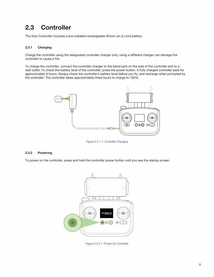
To charge the controller, connect the controller charger to the barrel jack on the side of the controller and to awall outlet. To check the battery level of the controller, press the power button. A fully charged controller lasts forapproximately 6 hours. Always check the controller’s battery level before you fly, and recharge when prompted bythe controller. The controller takes approximately three hours to charge to 100%.
Figure 2.3.1.1: Controller Charging
2.3.2 Powering
To power on the controller, press and hold the controller power button until you see the startup screen.
Figure 2.3.2.1: Power On Controller
9
2.4 PropellersSolo uses two types of self-tightening propellers, indicated by the color of the circle at the center of the propeller.
2.4.1 Attaching
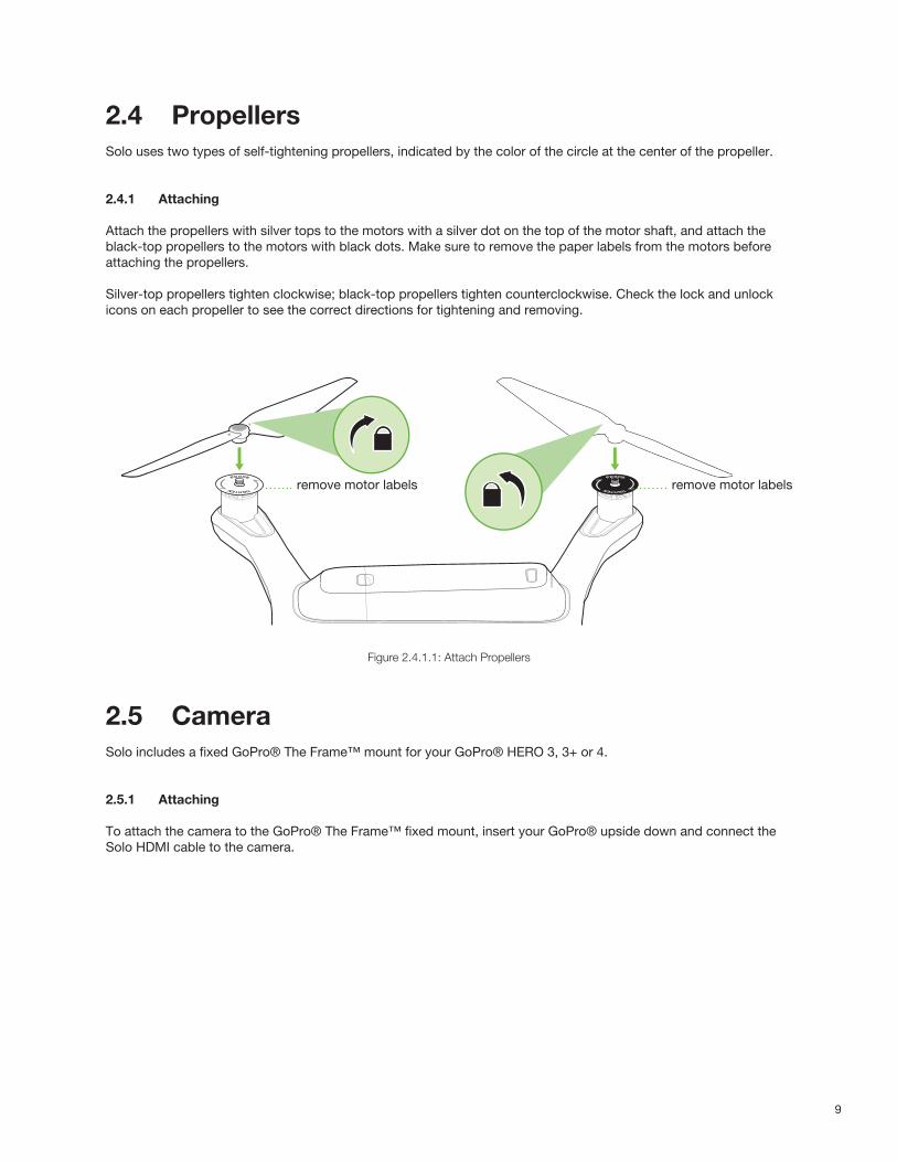
Attach the propellers with silver tops to the motors with a silver dot on the top of the motor shaft, and attach theblack-top propellers to the motors with black dots. Make sure to remove the paper labels from the motors beforeattaching the propellers.
Silver-top propellers tighten clockwise; black-top propellers tighten counterclockwise. Check the lock and unlockicons on each propeller to see the correct directions for tightening and removing.
Figure 2.4.1.1: Attach Propellers
2.5 CameraSolo includes a fixed GoPro® The Frame™ mount for your GoPro® HERO 3, 3+ or 4.
2.5.1 Attaching
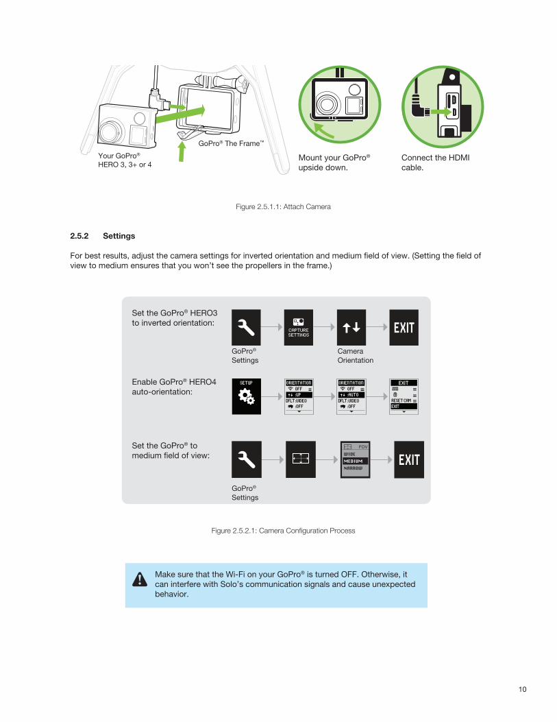
To attach the camera to the GoPro® The Frame™ fixed mount, insert your GoPro® upside down and connect the Solo HDMI cable to the camera.
remove motor labelsremove motor labels
10
Figure 2.5.1.1: Attach Camera
2.5.2 Settings
For best results, adjust the camera settings for inverted orientation and medium field of view. (Setting the field of view to medium ensures that you won’t see the propellers in the frame.)
Figure 2.5.2.1: Camera Configuration Process
GoPro® The Frame™
Your GoPro® HERO 3, 3+ or 4
Mount your GoPro® upside down.
Connect the HDMI cable.
Set the GoPro® HERO3 to inverted orientation:
Enable GoPro® HERO4auto-orientation:
Set the GoPro® to medium field of view:
GoPro® Settings
Camera Orientation
GoPro® Settings
ORIENTATIONSETUPOFF
:OFF
:UP:VIDEO
ORIENTATIONOFF
:OFF
:AUTO:VIDEO
EXIT
EXITRESET CAM
ORIENTATIONSETUPOFF
:OFF
:UP:VIDEO
ORIENTATIONOFF
:OFF
:AUTO:VIDEO
EXIT
EXITRESET CAM
Make sure that the Wi-Fi on your GoPro® is turned OFF. Otherwise, it can interfere with Solo’s communication signals and cause unexpected behavior.
11
2.6 Mobile App The Solo App provides a streaming-video link to a mobile device and a simple graphic interface for interacting withSmart Shots and other advanced Solo features.
2.6.1 Install
Visit 3dr.com/soloapp or download “3DR Solo” from the App Store or Google Play Store. 3DR Solo works with iOS 8.0 or later and Android 4.3 or later. For Android, you must also install the “3DR Services” app to your device.
2.6.2 Connect to Solo
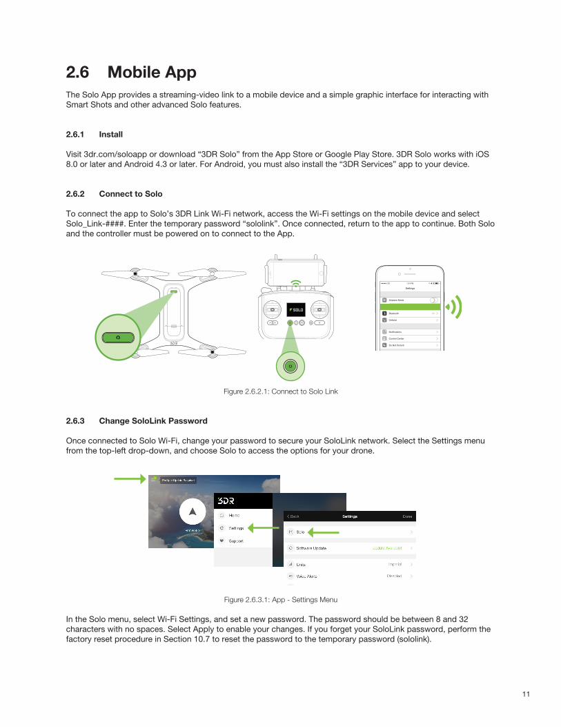
To connect the app to Solo’s 3DR Link Wi-Fi network, access the Wi-Fi settings on the mobile device and select Solo_Link-####. Enter the temporary password “sololink”. Once connected, return to the app to continue. Both Solo and the controller must be powered on to connect to the App.
Figure 2.6.2.1: Connect to Solo Link
2.6.3 Change SoloLink Password
Once connected to Solo Wi-Fi, change your password to secure your SoloLink network. Select the Settings menu from the top-left drop-down, and choose Solo to access the options for your drone.
Figure 2.6.3.1: App - Settings Menu
In the Solo menu, select Wi-Fi Settings, and set a new password. The password should be between 8 and 32 characters with no spaces. Select Apply to enable your changes. If you forget your SoloLink password, perform the factory reset procedure in Section 10.7 to reset the password to the temporary password (sololink).
Settings
Airplane Mode
WI-FI
Bluetooth
Cellular
Solo_Link-####
On
Notifications
Control Center
Do Not Disturb
7:34 PMLTE
General
Sounds
Wallpapers & Brightness
Privacy
12
Figure 2.6.3.2: App - Wi-Fi Settings
2.6.4 Update
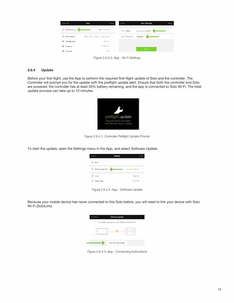
Before your first flight, use the App to perform the required first-flight update of Solo and the controller. TheController will prompt you for the update with the preflight update alert. Ensure that both the controller and Soloare powered, the controller has at least 50% battery remaining, and the app is connected to Solo Wi-Fi. The totalupdate process can take up to 10 minutes.
Figure 2.6.4.1: Controller Preflight Update Prompt
To start the update, open the Settings menu in the App, and select Software Update.
Figure 2.6.4.2: App - Software Update
Because your mobile device has never connected to this Solo before, you will need to link your device with SoloWi-Fi (SoloLink).
Figure 2.6.4.3: App - Connecting Instructions
ARTOO UPDATE SCREEN FEEDBACK V10C
Update Requirement Screen
Controller updated
Controller update in progress screenIs displayed after user initiates update in app.Persists until controller update is successful.
Update complete feedback.Tells the user that controller update was successful.
HAPTIC: Three 20 millisecond pulses, to communicate update completion.
A-Press required to dimiss (same as current implementation)
Controller updatingUpdate will take about 5 minutes
Please ensure charger is connectedController may go dark while updating
Please reconnect to Sololink wifi
Press to continue
Returns user to hold-Fly-button screen
Green Solo LEDs (showing update complete) change to standard red and white when this screen is displayed
preflight updateRequired before first flight!
Use 3DR Solo App to update
update errorSolo and Controller have different software versions
Use 3DR Solo app to update the system
Waiting for SoloPersists until Solo reconnects
or
Artoo auto-shutdown
Solo-Artoo version mismatchIf Solo and Artoo have a mismatched version on startup this message is displayed in the update �ow in place of the “pre�ight update” screen.
Press when LEDs are green
Update complete (Connects to matching version Solo)
Prompt stays on screen until update is successful.
Post Unlock BehaviorAfter system is unlocked, user should be able to �y using Artoo / Soloversions that were last successfully installed. (Even if they have failed in their most recent update attempt.)
Update unsuccessful (Artoo and Solo version mismatch)
Update TimeoutIf update does not complete in X minutesUpdate-unsuccessful screen is displayed
Update TimeoutIf update does not complete in X minutes“update-unsuccessful” screen is displayed
Update failureIf update fails, display “update unsuccessful”screen
update unsuccessfulPlease use 3DR Solo app to try
the update again
waiting for Solo
Cable Cam Orbit
FLY 12
FLYHold to start motors
13
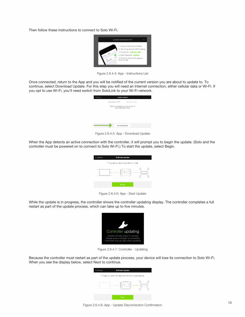
Then follow these instructions to connect to Solo Wi-Fi.
Figure 2.6.4.4: App - Instructions List
Once connected, return to the App and you will be notified of the current version you are about to update to. To continue, select Download Update. For this step you will need an Internet connection, either cellular data or Wi-Fi. If you opt to use Wi-Fi, you’ll need switch from SoloLink to your Wi-Fi network.
Figure 2.6.4.5: App - Download Update
When the App detects an active connection with the controller, it will prompt you to begin the update. (Solo and the controller must be powered on to connect to Solo Wi-Fi.) To start the update, select Begin.
Figure 2.6.4.6: App - Start Update
While the update is in progress, the controller shows the controller updating display. The controller completes a full restart as part of the update process, which can take up to five minutes.
Figure 2.6.4.7: Controller - Updating
Because the controller must restart as part of the update process, your device will lose its connection to Solo Wi-Fi. When you see the display below, select Next to continue.
Figure 2.6.4.8: App - Update Disconnection Confirmation
ARTOO UPDATE SCREEN FEEDBACK V10C
Update Requirement Screen
Controller updated
Controller update in progress screenIs displayed after user initiates update in app.Persists until controller update is successful.
Update complete feedback.Tells the user that controller update was successful.
HAPTIC: Three 20 millisecond pulses, to communicate update completion.
A-Press required to dimiss (same as current implementation)
Controller updatingUpdate will take about 5 minutes
Please ensure charger is connectedController may go dark while updating
Please reconnect to Sololink wifi
Press to continue
Returns user to hold-Fly-button screen
Green Solo LEDs (showing update complete) change to standard red and white when this screen is displayed
preflight updateRequired before first flight!
Use 3DR Solo App to update
update errorSolo and Controller have different software versions
Use 3DR Solo app to update the system
Waiting for SoloPersists until Solo reconnects
or
Artoo auto-shutdown
Solo-Artoo version mismatchIf Solo and Artoo have a mismatched version on startup this message is displayed in the update �ow in place of the “pre�ight update” screen.
Press when LEDs are green
Update complete (Connects to matching version Solo)
Prompt stays on screen until update is successful.
Post Unlock BehaviorAfter system is unlocked, user should be able to �y using Artoo / Soloversions that were last successfully installed. (Even if they have failed in their most recent update attempt.)
Update unsuccessful (Artoo and Solo version mismatch)
Update TimeoutIf update does not complete in X minutesUpdate-unsuccessful screen is displayed
Update TimeoutIf update does not complete in X minutes“update-unsuccessful” screen is displayed
Update failureIf update fails, display “update unsuccessful”screen
update unsuccessfulPlease use 3DR Solo app to try
the update again
waiting for Solo
Cable Cam Orbit
FLY 12
FLYHold to start motors
14
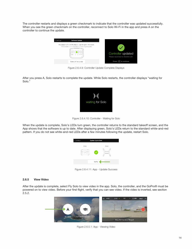
The controller restarts and displays a green checkmark to indicate that the controller was updated successfully. When you see the green checkmark on the controller, reconnect to Solo Wi-Fi in the app and press A on the controller to continue the update.
Figure 2.6.4.9: Controller Update Complete Displays
After you press A, Solo restarts to complete the update. While Solo restarts, the controller displays “waiting for Solo.”
Figure 2.6.4.10: Controller - Waiting for Solo
When the update is complete, Solo’s LEDs turn green, the controller returns to the standard takeoff screen, and the App shows that the software is up to date. After displaying green, Solo’s LEDs return to the standard white-and-red pattern. If you do not see white-and-red LEDs after a few minutes following the update, restart Solo.
Figure 2.6.4.11: App - Update Success
2.6.5 View Video
After the update is complete, select Fly Solo to view video in the app. Solo, the controller, and the GoPro® must be powered on to view video. Before your first flight, verify that you can see video. If the video is inverted, see section 2.5.2.
Figure 2.6.5.1: App - Viewing Video
ARTOO UPDATE SCREEN FEEDBACK V10C
Update Requirement Screen
Controller updated
Controller update in progress screenIs displayed after user initiates update in app.Persists until controller update is successful.
Update complete feedback.Tells the user that controller update was successful.
HAPTIC: Three 20 millisecond pulses, to communicate update completion.
A-Press required to dimiss (same as current implementation)
Controller updatingUpdate will take about 5 minutes
Please ensure charger is connectedController may go dark while updating
Please reconnect to Sololink wifi
Press to continue
Returns user to hold-Fly-button screen
Green Solo LEDs (showing update complete) change to standard red and white when this screen is displayed
preflight updateRequired before first flight!
Use 3DR Solo App to update
update errorSolo and Controller have different software versions
Use 3DR Solo app to update the system
Waiting for SoloPersists until Solo reconnects
or
Artoo auto-shutdown
Solo-Artoo version mismatchIf Solo and Artoo have a mismatched version on startup this message is displayed in the update �ow in place of the “pre�ight update” screen.
Press when LEDs are green
Update complete (Connects to matching version Solo)
Prompt stays on screen until update is successful.
Post Unlock BehaviorAfter system is unlocked, user should be able to �y using Artoo / Soloversions that were last successfully installed. (Even if they have failed in their most recent update attempt.)
Update unsuccessful (Artoo and Solo version mismatch)
Update TimeoutIf update does not complete in X minutesUpdate-unsuccessful screen is displayed
Update TimeoutIf update does not complete in X minutes“update-unsuccessful” screen is displayed
Update failureIf update fails, display “update unsuccessful”screen
update unsuccessfulPlease use 3DR Solo app to try
the update again
waiting for Solo
Cable Cam Orbit
FLY 12
FLYHold to start motors
15
3 The Solo GimbalThe optional Solo Gimbal holds your GoPro® camera and lets you control it remotely. It taps Solo’s intelligence to get perfectly automated shots, plus rock-solid footage, GoPro® control and charging, and long-range HD video feed. With the 3-Axis Solo Gimbal, you get:
• Smooth and fluid HD footage every flight.
• Start and stop recording (HERO4 models) while you fly so you can pick and choose the shots you want.
• Footage stabilized to within 0.1 degree of pointing accuracy for enhanced Smart Shots.
• Fine-grain camera tilt control, including angle presets and instant speed adjustment.
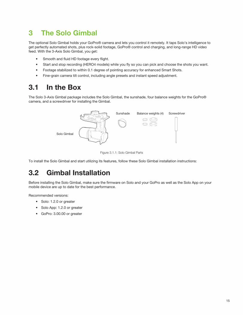
3.1 In the BoxThe Solo 3-Axis Gimbal package includes the Solo Gimbal, the sunshade, four balance weights for the GoPro® camera, and a screwdriver for installing the Gimbal.
Figure 3.1.1: Solo Gimbal Parts
To install the Solo Gimbal and start utilizing its features, follow these Solo Gimbal installation instructions:
3.2 Gimbal InstallationBefore installing the Solo Gimbal, make sure the firmware on Solo and your GoPro as well as the Solo App on your mobile device are up to date for the best performance.
Recommended versions:
• Solo: 1.2.0 or greater
• Solo App: 1.2.0 or greater
• GoPro: 3.00.00 or greater
Balance weights (4)
Solo Gimbal
Sunshade Screwdriver
16
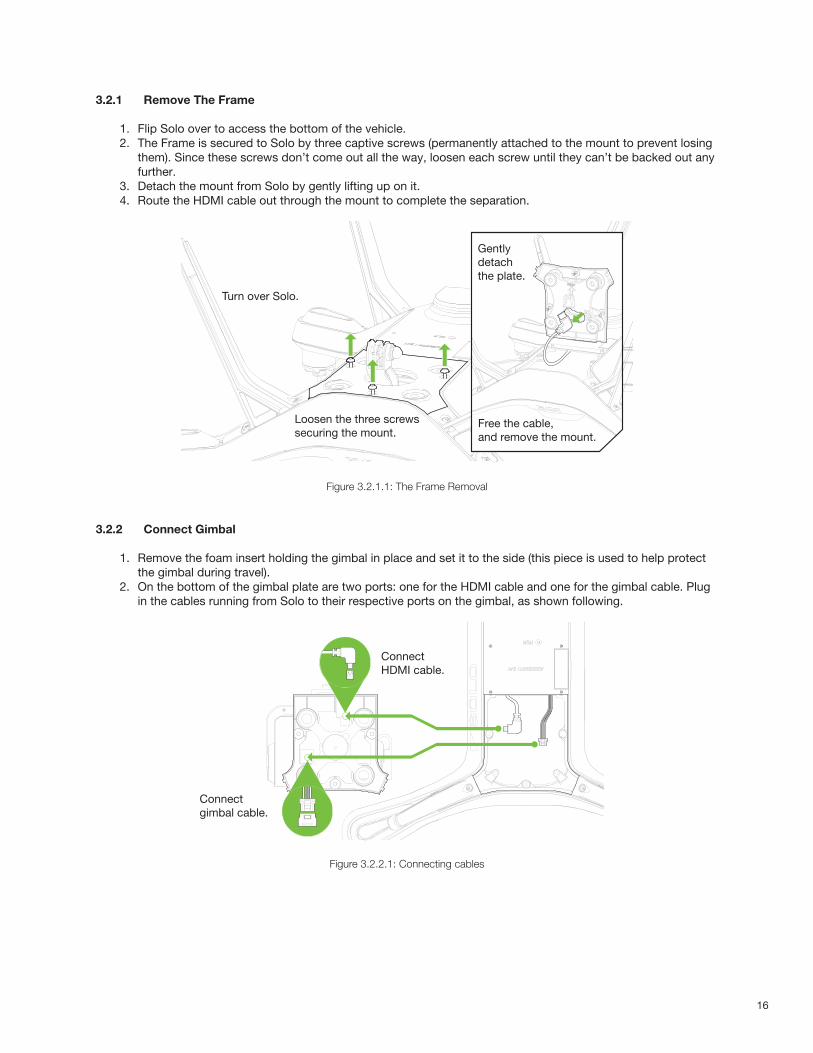
3.2.1 Remove The Frame
1. Flip Solo over to access the bottom of the vehicle.2. The Frame is secured to Solo by three captive screws (permanently attached to the mount to prevent losing
them). Since these screws don’t come out all the way, loosen each screw until they can’t be backed out any further.
3. Detach the mount from Solo by gently lifting up on it.4. Route the HDMI cable out through the mount to complete the separation.
Figure 3.2.1.1: The Frame Removal
3.2.2 Connect Gimbal
1. Remove the foam insert holding the gimbal in place and set it to the side (this piece is used to help protect the gimbal during travel).
2. On the bottom of the gimbal plate are two ports: one for the HDMI cable and one for the gimbal cable. Plug in the cables running from Solo to their respective ports on the gimbal, as shown following.
Connect gimbal cable.
Connect HDMI cable.
Figure 3.2.2.1: Connecting cables
Turn over Solo.
Loosen the three screws securing the mount.
Gently detachthe plate.
Free the cable, and remove the mount.
17
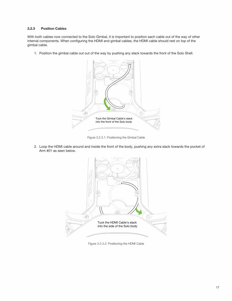
3.2.3 Position Cables
With both cables now connected to the Solo Gimbal, it is important to position each cable out of the way of other internal components. When configuring the HDMI and gimbal cables, the HDMI cable should rest on top of the gimbal cable.
1. Position the gimbal cable out out of the way by pushing any slack towards the front of the Solo Shell.
Tuck the Gimbal Cable’s slackinto the front of the Solo body
Figure 3.2.3.1: Positioning the Gimbal Cable
2. Loop the HDMI cable around and inside the front of the body, pushing any extra slack towards the pocket of Arm #01 as seen below.
Tuck the HDMI Cable’s slackinto the side of the Solo body
Figure 3.2.3.2: Positioning the HDMI Cable
18
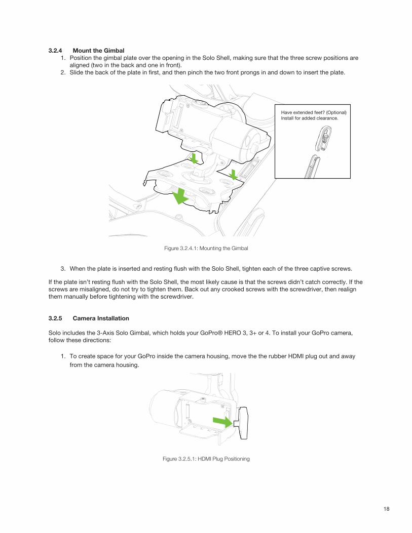
3.2.4 Mount the Gimbal1. Position the gimbal plate over the opening in the Solo Shell, making sure that the three screw positions are
aligned (two in the back and one in front).2. Slide the back of the plate in first, and then pinch the two front prongs in and down to insert the plate.
Figure 3.2.4.1: Mounting the Gimbal
3. When the plate is inserted and resting flush with the Solo Shell, tighten each of the three captive screws.
If the plate isn’t resting flush with the Solo Shell, the most likely cause is that the screws didn’t catch correctly. If the screws are misaligned, do not try to tighten them. Back out any crooked screws with the screwdriver, then realign them manually before tightening with the screwdriver.
3.2.5 Camera Installation
Solo includes the 3-Axis Solo Gimbal, which holds your GoPro® HERO 3, 3+ or 4. To install your GoPro camera, follow these directions:
1. To create space for your GoPro inside the camera housing, move the the rubber HDMI plug out and away from the camera housing.
Figure 3.2.5.1: HDMI Plug Positioning
Have extended feet? (Optional)Install for added clearance.
19
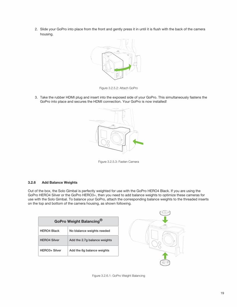
2. Slide your GoPro into place from the front and gently press it in until it is flush with the back of the camera housing.
Figure 3.2.5.2: Attach GoPro
3. Take the rubber HDMI plug and insert into the exposed side of your GoPro. This simultaneously fastens the GoPro into place and secures the HDMI connection. Your GoPro is now installed!
Figure 3.2.5.3: Fasten Camera
3.2.6 Add Balance Weights
Out of the box, the Solo Gimbal is perfectly weighted for use with the GoPro HERO4 Black. If you are using the GoPro HERO4 Silver or the GoPro HERO3+, then you need to add balance weights to optimize these cameras for use with the Solo Gimbal. To balance your GoPro, attach the corresponding balance weights to the threaded inserts on the top and bottom of the camera housing, as shown following.
Figure 3.2.6.1: GoPro Weight Balancing
GoPro Weight Balancing®
HERO4 Black No blalance weights needed
HERO4 Silver Add the 2.7g balance weights
HERO3+ Silver Add the 6g balance weights
20
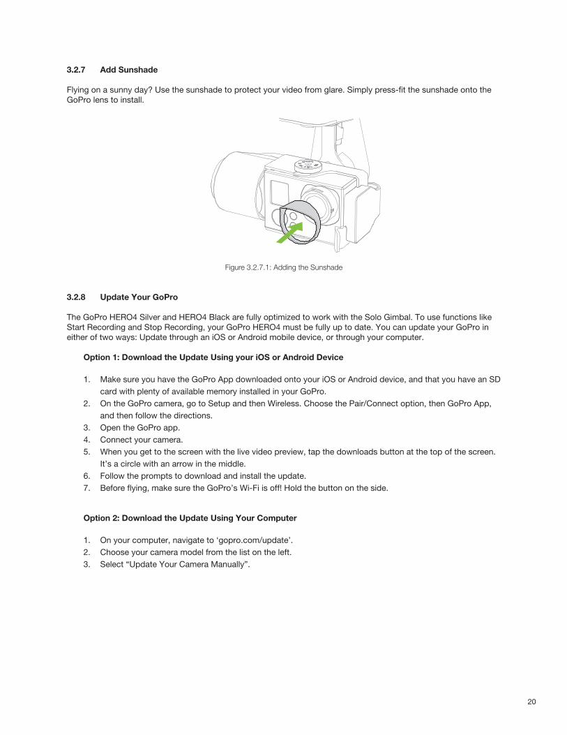
3.2.7 Add Sunshade
Flying on a sunny day? Use the sunshade to protect your video from glare. Simply press-fit the sunshade onto the GoPro lens to install.
Figure 3.2.7.1: Adding the Sunshade
3.2.8 Update Your GoPro
The GoPro HERO4 Silver and HERO4 Black are fully optimized to work with the Solo Gimbal. To use functions like Start Recording and Stop Recording, your GoPro HERO4 must be fully up to date. You can update your GoPro in either of two ways: Update through an iOS or Android mobile device, or through your computer.
Option 1: Download the Update Using your iOS or Android Device
1. Make sure you have the GoPro App downloaded onto your iOS or Android device, and that you have an SD card with plenty of available memory installed in your GoPro.
2. On the GoPro camera, go to Setup and then Wireless. Choose the Pair/Connect option, then GoPro App, and then follow the directions.
3. Open the GoPro app.4. Connect your camera.5. When you get to the screen with the live video preview, tap the downloads button at the top of the screen.
It’s a circle with an arrow in the middle.6. Follow the prompts to download and install the update.7. Before flying, make sure the GoPro’s Wi-Fi is off! Hold the button on the side.
Option 2: Download the Update Using Your Computer
1. On your computer, navigate to ‘gopro.com/update’.2. Choose your camera model from the list on the left.3. Select “Update Your Camera Manually”.
21
4. Follow the instructions to register and update your GoPro.
3.2.9 Recommended GoPro Settings
For superior results, adjust your camera settings to these recommended values.
Figure 3.2.9.1: Camera Configuration Process
3.3 Gimbal OperationThe Solo Gimbal is a nearly autonomous tool. For example, it handles camera balancing and stabilization for you automatically. However, we recommend that you be aware of some operational aspects of the Solo Gimbal, as well as a handful of controls you can use.
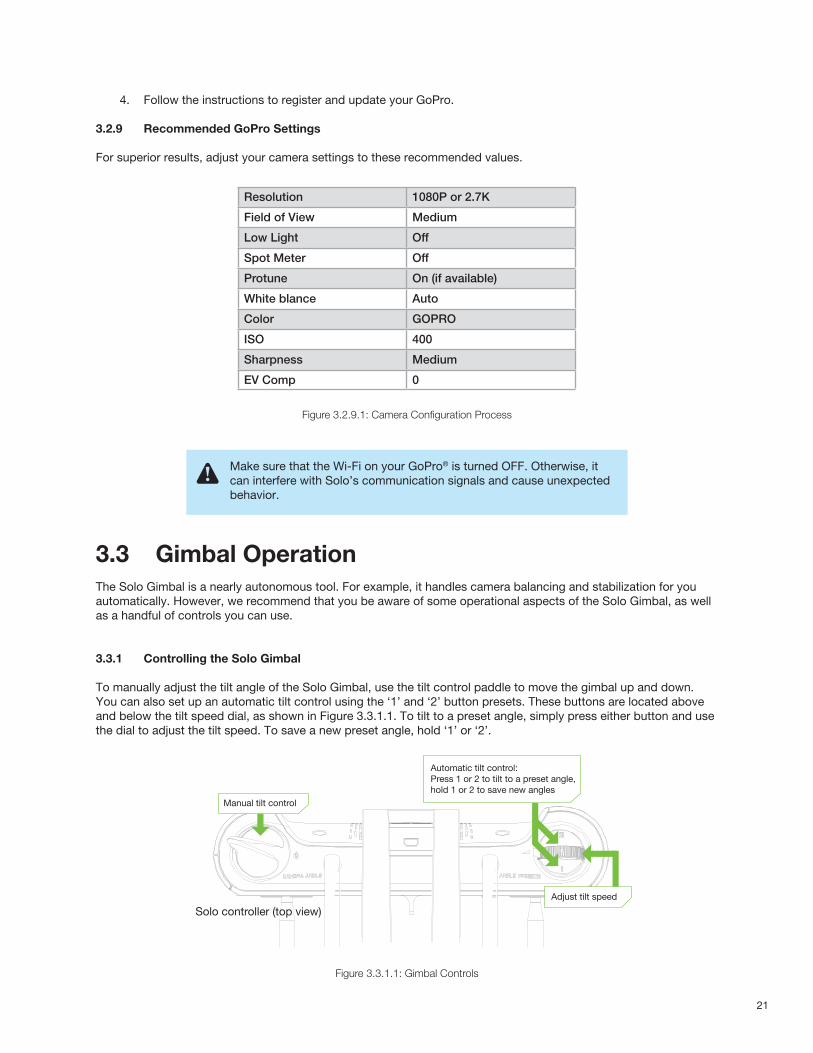
3.3.1 Controlling the Solo Gimbal
To manually adjust the tilt angle of the Solo Gimbal, use the tilt control paddle to move the gimbal up and down. You can also set up an automatic tilt control using the ‘1’ and ‘2’ button presets. These buttons are located above and below the tilt speed dial, as shown in Figure 3.3.1.1. To tilt to a preset angle, simply press either button and use the dial to adjust the tilt speed. To save a new preset angle, hold ‘1’ or ‘2’.
Figure 3.3.1.1: Gimbal Controls
Resolution 1080P or 2.7K
Field of View Medium
Low Light Off
Spot Meter Off
Protune On (if available)
White blance Auto
Color GOPRO
ISO 400
Sharpness Medium
EV Comp 0
Make sure that the Wi-Fi on your GoPro® is turned OFF. Otherwise, it can interfere with Solo’s communication signals and cause unexpected behavior.
Solo controller (top view)
Automatic tilt control:Press 1 or 2 to tilt to a preset angle,hold 1 or 2 to save new angles
Manual tilt control
Adjust tilt speed
22
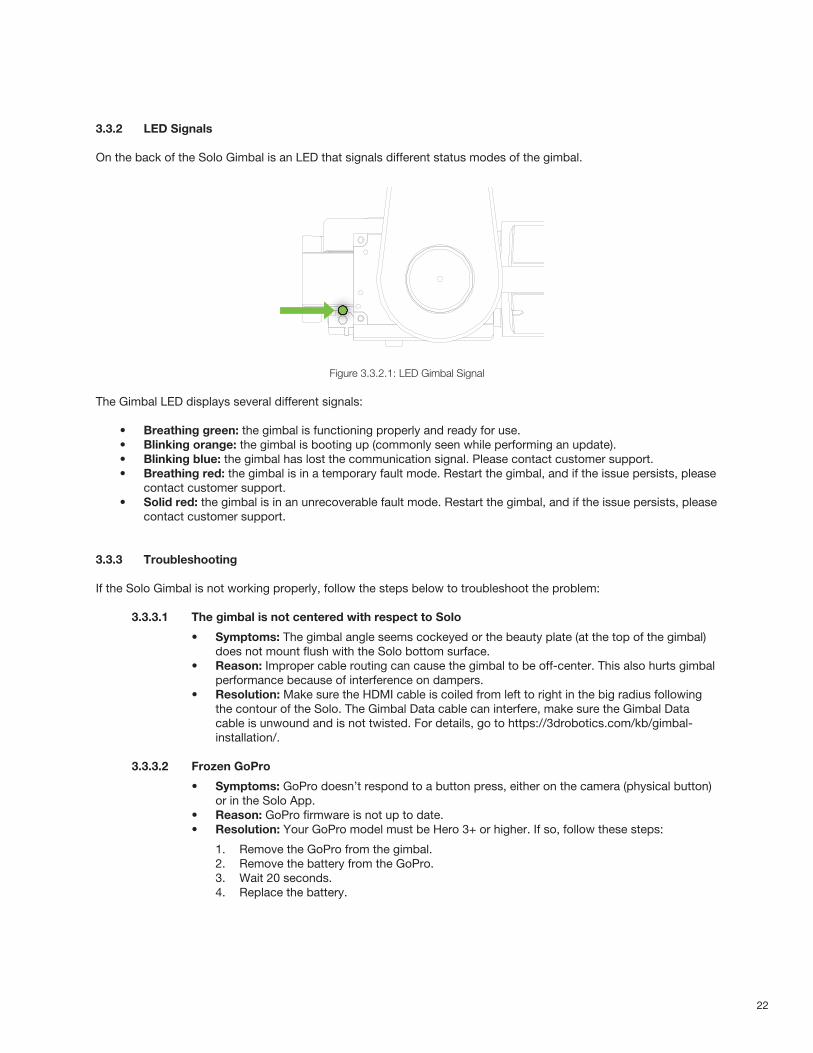
3.3.2 LED Signals
On the back of the Solo Gimbal is an LED that signals different status modes of the gimbal.
Figure 3.3.2.1: LED Gimbal Signal
The Gimbal LED displays several different signals:
• Breathing green: the gimbal is functioning properly and ready for use. • Blinking orange: the gimbal is booting up (commonly seen while performing an update). • Blinking blue: the gimbal has lost the communication signal. Please contact customer support. • Breathing red: the gimbal is in a temporary fault mode. Restart the gimbal, and if the issue persists, please
contact customer support. • Solid red: the gimbal is in an unrecoverable fault mode. Restart the gimbal, and if the issue persists, please
contact customer support.
3.3.3 Troubleshooting
If the Solo Gimbal is not working properly, follow the steps below to troubleshoot the problem:
3.3.3.1 The gimbal is not centered with respect to Solo
• Symptoms: The gimbal angle seems cockeyed or the beauty plate (at the top of the gimbal) does not mount flush with the Solo bottom surface.
• Reason: Improper cable routing can cause the gimbal to be off-center. This also hurts gimbal performance because of interference on dampers.
• Resolution: Make sure the HDMI cable is coiled from left to right in the big radius following the contour of the Solo. The Gimbal Data cable can interfere, make sure the Gimbal Data cable is unwound and is not twisted. For details, go to https://3drobotics.com/kb/gimbal-installation/.
3.3.3.2 Frozen GoPro
• Symptoms: GoPro doesn’t respond to a button press, either on the camera (physical button) or in the Solo App.
• Reason: GoPro firmware is not up to date.• Resolution: Your GoPro model must be Hero 3+ or higher. If so, follow these steps:
1. Remove the GoPro from the gimbal.2. Remove the battery from the GoPro.3. Wait 20 seconds.4. Replace the battery.
23
5. Power on the GoPro. At this point, make sure the GoPro firmware is the latest version.
3.3.3.3 The gimbal is not turning on or responding
• Symptoms: Gimbal appears not to be receiving power.• Reason: Possible connectivity issues.• Resolution: Check the LED on the gimbal (behind the GoPro) and refer to the color guide
in Section 3.3.2. If the LED is off, make sure the gimbal connector is plugged in and seated properly.
If none of the preceding steps resolved your gimbal issue, please contact customer support at 3dr.com/support.
24
4 SafetyThe following best practices will help ensure safe, successful flights and help reduce the risk of accident and serious injury:
• Always fly under adult supervision and with your full attention at all times. • Do not fly under the influence of drugs or alcohol or when your ability to operate Solo safely is impaired.• Use common sense to avoid unsafe situations and always operate Solo responsibly.
4.1 LocationWhen choosing an appropriate place to fly Solo, keep these location factors in mind:
• Don’t fly Solo indoors. • Always fly outside in clear, open areas at a safe distance from yourself, other people, power lines,
animals, vehicles, trees, and buildings. • When flying in areas with potential hazards, maintain a distance of at least 100 feet (30 m) from any
people, vehicles, or structures. As the operator, you are responsible for navigating Solo to avoid obstacles, including during Smart Shots.
• Don’t fly within five miles of an airport or within any airspace restricted by your local, state, or national airspace authority. As the operator, you are responsible for knowing and understanding the regulations that govern small, unmanned aircraft like Solo in your jurisdiction.
4.2 Environmental AwarenessDon’t fly Solo in extreme weather conditions such as rain, high winds, snow, or fog. Such weather conditions can permanently damage Solo or cause instability in flight.
Before flying, determine the boundaries of the safe flying area at your location. Be aware of any risks, including bodies of water, structures, trees, power lines, etc, and designate a few areas where you can land Solo in case of an unsafe situation. Throughout your flight, be prepared to recover Solo manually or use an emergency procedure if Solo flies outside the safe flying area.
4.3 Visual Line of SightAlways fly Solo within your visual line of sight. Don’t let Solo get so far away from you that you cannot see its orientation or so that any physical obstructions block your view of Solo.
Read and understand these important safety instructions before your first flight to help reduce the risk of accident and serious injury.
Physical obstructions can also block communication signals with the controller, causing Solo to attempt to Return Home along an obstructed path
25
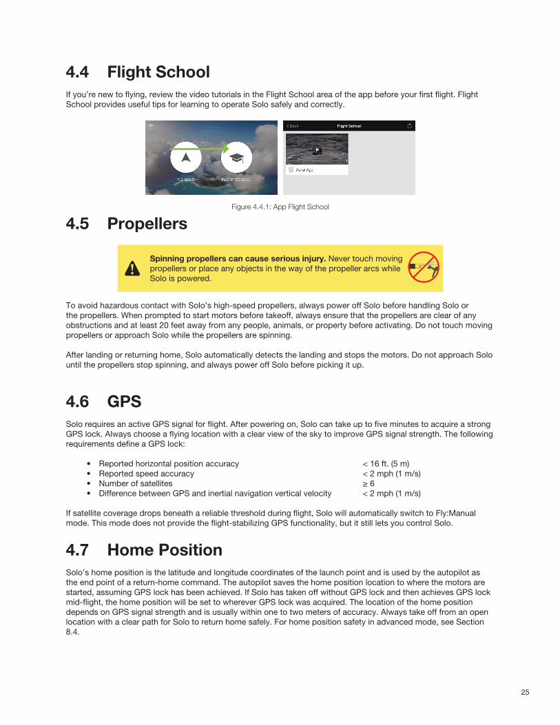
4.4 Flight SchoolIf you’re new to flying, review the video tutorials in the Flight School area of the app before your first flight. Flight School provides useful tips for learning to operate Solo safely and correctly.
Figure 4.4.1: App Flight School
4.5 Propellers
To avoid hazardous contact with Solo’s high-speed propellers, always power off Solo before handling Solo or the propellers. When prompted to start motors before takeoff, always ensure that the propellers are clear of any obstructions and at least 20 feet away from any people, animals, or property before activating. Do not touch moving propellers or approach Solo while the propellers are spinning.
After landing or returning home, Solo automatically detects the landing and stops the motors. Do not approach Solo until the propellers stop spinning, and always power off Solo before picking it up.
4.6 GPSSolo requires an active GPS signal for flight. After powering on, Solo can take up to five minutes to acquire a strong GPS lock. Always choose a flying location with a clear view of the sky to improve GPS signal strength. The following requirements define a GPS lock:
• Reported horizontal position accuracy < 16 ft. (5 m)• Reported speed accuracy < 2 mph (1 m/s)• Number of satellites ≥ 6• Difference between GPS and inertial navigation vertical velocity < 2 mph (1 m/s)
If satellite coverage drops beneath a reliable threshold during flight, Solo will automatically switch to Fly:Manual mode. This mode does not provide the flight-stabilizing GPS functionality, but it still lets you control Solo.
4.7 Home PositionSolo’s home position is the latitude and longitude coordinates of the launch point and is used by the autopilot asthe end point of a return-home command. The autopilot saves the home position location to where the motors arestarted, assuming GPS lock has been achieved. If Solo has taken off without GPS lock and then achieves GPS lockmid-flight, the home position will be set to wherever GPS lock was acquired. The location of the home positiondepends on GPS signal strength and is usually within one to two meters of accuracy. Always take off from an openlocation with a clear path for Solo to return home safely. For home position safety in advanced mode, see Section8.4.
Spinning propellers can cause serious injury. Never touch moving propellers or place any objects in the way of the propeller arcs while Solo is powered.
400 ft400 ft

26
4.8 Altitude LimitAlways fly at appropriate altitudes for your flying location and local regulations. Solo cannot avoid obstacles on itsown, so always select altitudes that avoid any obstacles, such as trees, buildings, and power lines.
Solo includes a safety fence enabled by default at 150 ft. (46 m). If Solo reaches the altitude limit, it stops ascending and limits throttle input to stay below the altitude limit. To adjust the altitude limit, see Section 8.7. FAAregulations mandate a maximum altitude of 400 ft. to avoid potential conflicts with manned aircraft and represents asafe line-of-sight altitude.
4.9 Emergency ProceduresIf you experience a problem in flight, use one of the following emergency procedures to stop Solo, end your flight, or shut off the motors.
4.9.1 Pause
The controller’s Pause button allows you to stop Solo in mid-air. Solo hovers at the paused location until given another command. Use the Pause button to stop Solo from hitting an obstacle or to reorient Solo for navigation. During Return Home or Land, you can pause Solo and stop the landing by pressing Pause. Pause is available only with GPS lock.
4.9.2 Regain Manual Control
Keep the controller easily accessible at all times during flight, including during Smart Shots, and be prepared to regain manual control at any time. To return to standard flight during Smart Shots, Return Home, or Land, press the Fly button.
4.9.3 Return Home
If Solo acquired GPS lock prior to takeoff, you can return it to the launch point and land by pressing Return Home on the controller. If you receive a low-battery notification or want to quickly end your flight, press Return Home. Solo does not avoid obstacles while returning home; always verify that the return path is clear before activating Return Home.
4.9.4 Land
To land Solo at its current position, press and hold the Fly button. To exit the landing procedure at any time, lift the throttle. If Solo does not have GPS lock, automatic positioning is not available as Solo descends, and drifting can occur depending on environmental conditions.
27
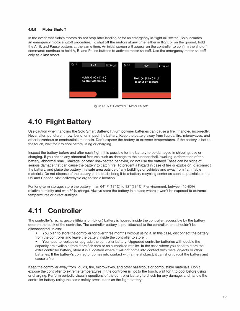
4.9.5 Motor Shutoff
In the event that Solo’s motors do not stop after landing or for an emergency in-flight kill switch, Solo includes an emergency motor shutoff procedure. To shut off the motors at any time, either in flight or on the ground, hold the A, B, and Pause buttons at the same time. An initial screen will appear on the controller to confirm the shutoff command; continue to hold A, B, and Pause buttons to activate motor shutoff. Use the emergency motor shutoff only as a last resort.
Figure 4.9.5.1: Controller - Motor Shutoff
4.10 Flight BatteryUse caution when handling the Solo Smart Battery; lithium polymer batteries can cause a fire if handled incorrectly. Never alter, puncture, throw, bend, or impact the battery. Keep the battery away from liquids, fire, microwaves, and other hazardous or combustible materials. Don’t expose the battery to extreme temperatures. If the battery is hot to the touch, wait for it to cool before using or charging.
Inspect the battery before and after each flight. It is possible for the battery to be damaged in shipping, use or charging. If you notice any abnormal features such as damage to the exterior shell, swelling, deformation of the battery, abnormal smell, leakage, or other unexpected behavior, do not use the battery! These can be signs of serious damage that can cause the battery to catch fire. To prevent a hazard in case of fire or explosion, disconnect the battery, and place the battery in a safe area outside of any buildings or vehicles and away from flammable materials. Do not dispose of the battery in the trash; bring it to a battery recycling center as soon as possible. In the US and Canada, visit call2recycle.org to find a location.
For long-term storage, store the battery in an 64° F (18° C) to 82° (28° C) F environment, between 45-85% relative humidity and with 50% charge. Always store the battery in a place where it won’t be exposed to extreme temperatures or direct sunlight.
4.11 ControllerThe controller’s rechargeable lithium ion (Li-ion) battery is housed inside the controller, accessible by the battery door on the back of the controller. The controller battery is pre-attached to the controller, and shouldn’t be disconnected unless:
• You plan to store the controller for over three months without using it. In this case, disconnect the battery from the controller and leave the battery inside the controller to store it.• You need to replace or upgrade the controller battery. Upgraded controller batteries with double the capacity are available from store.3dr.com or an authorized retailer. In the case where you need to store the extra controller battery, store it in a location where it will not come into contact with metal objects or other batteries. If the battery’s connector comes into contact with a metal object, it can short circuit the battery and cause a fire.
Keep the controller away from liquids, fire, microwaves, and other hazardous or combustible materials. Don’t expose the controller to extreme temperatures. If the controller is hot to the touch, wait for it to cool before using or charging. Perform periodic visual inspections of the controller battery to check for any damage, and handle the controller battery using the same safety precautions as the flight battery.
KILL SWITCH UI - EMERGENCY MOTOR SHUTOFF
Progress bar completesAfter 3000 millisecond hold
Shuto� BannerBanner shows shuto� taking place
PERSISTENT: banner persists until user:
-rearms with Fly button
-restarts vehicle
Kill Switch FeedbackIf users holds AB + Pause in �ightnoti�cation is displayed
User holds AB + Pause to shut o� motors
Spot lock
Hold + to shut off motors
FLY 12
Spot lock
Hold + to shut off motors
FLY 12
Cable Cam Orbit
5FT
0FT
HOME
30%
FLIGHT BATTERY
ALTITUDE
LAND12
MOTOR SHUTOFF ACTIVATED
28
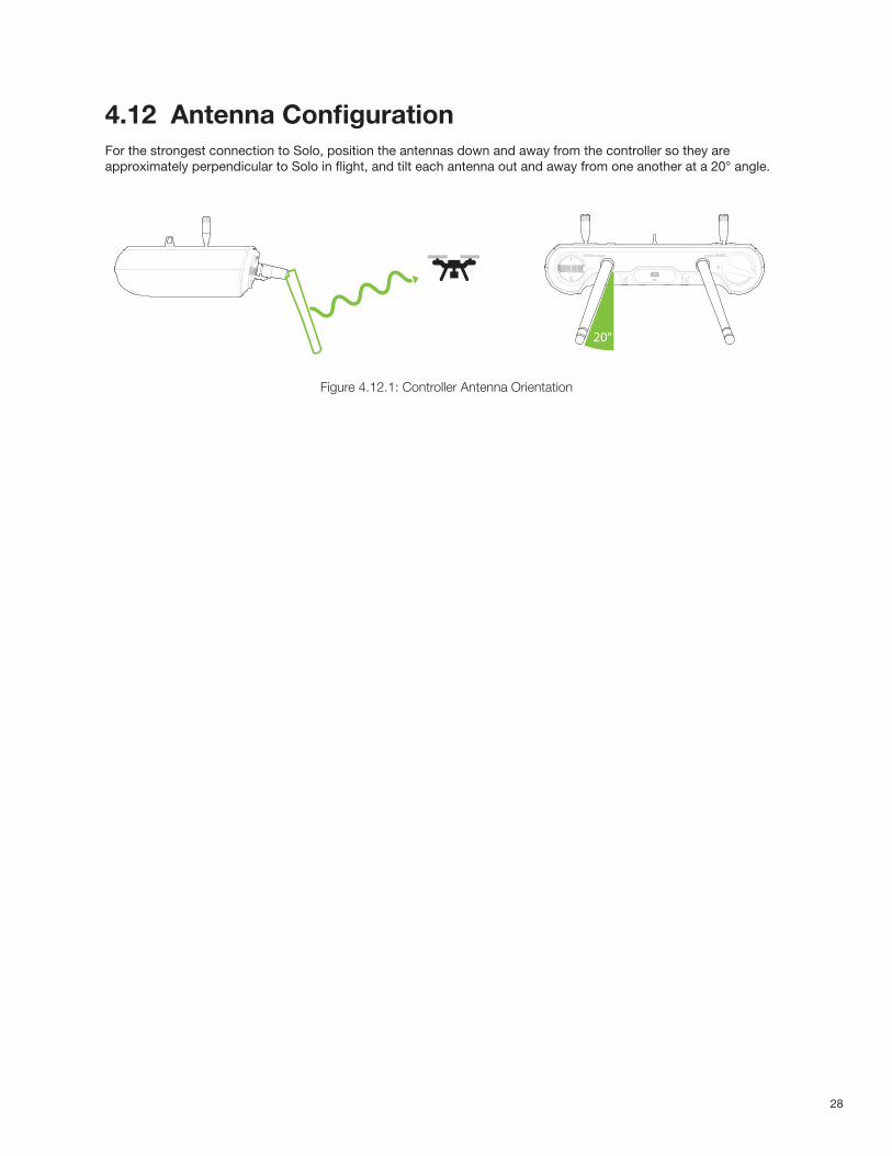
4.12 Antenna Configuration For the strongest connection to Solo, position the antennas down and away from the controller so they are approximately perpendicular to Solo in flight, and tilt each antenna out and away from one another at a 20° angle.
Figure 4.12.1: Controller Antenna Orientation
20°
29
5 First FlightThis section covers basic Solo flight procedures, including takeoff, landing, and manual control.
5.1 Preflight ChecklistBefore flying, check the following conditions:
5.1.1 Location
» Your current location and environmental conditions are suitable for flight. (Section 4.1) » Solo is on a level surface at a clear launch point a sufficient distance from yourself and others. (Section 4.1)
5.1.2 Components
» The propellers are correctly attached. (Section 2.4) » The propellers can spin smoothly and without obstruction when turned. » No components on Solo appear loose or damaged.
5.1.3 Power
» The controller is powered on with at least 50% charge. (Section 2.3) » Solo is powered on with a fully charged battery. (Section 2.2)
5.1.4 Video (Optional)
» The Solo app is connected to Solo and streaming video. (Section 2.6) » The GoPro® is recording. If have the Solo Gimbal and the GoPro HERO4, you can start and stop recording mid-
flight.
5.2 TakeoffThe takeoff process has two steps: start the motors, then take off. Always place Solo at a clear launch point for takeoff, at least 20 feet away from you, other people, and structures.
5.2.1 Activating Motors
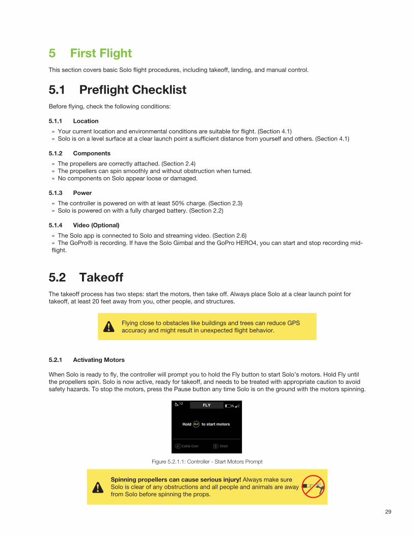
When Solo is ready to fly, the controller will prompt you to hold the Fly button to start Solo’s motors. Hold Fly until the propellers spin. Solo is now active, ready for takeoff, and needs to be treated with appropriate caution to avoid safety hazards. To stop the motors, press the Pause button any time Solo is on the ground with the motors spinning.
Figure 5.2.1.1: Controller - Start Motors Prompt
Flying close to obstacles like buildings and trees can reduce GPS accuracy and might result in unexpected flight behavior.
MOTOR START & TAKEOFF V4
Fly button safety sequenceProgress bar feedback while user holdsdown “Fly” button.
Takeo� promptWhen motor-on progress bar is �lled, motor-on text switches to takeo� prompt.
Haptic: press and hold feedback is given.
Motors o�Landing screen after startup, before motorsare turned on.
Cable Cam Orbit
FLY 12
FLYHold to start motors
Cable Cam Orbit
FLY 12
FLYHold to start motors
Cable Cam Orbit
FLY 12
FLYHold to start motors
Spinning propellers can cause serious injury! Always make sure Solo is clear of any obstructions and all people and animals are away from Solo before spinning the props.
400 ft400 ft
30
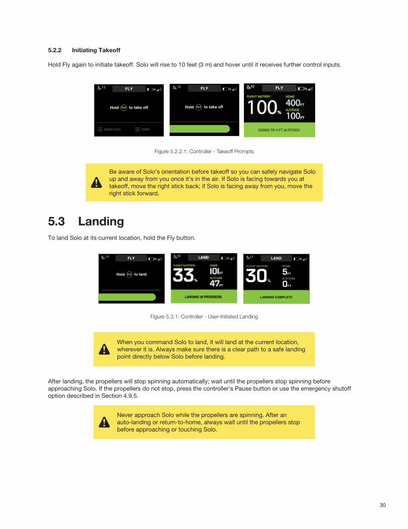
5.2.2 Initiating Takeoff
Hold Fly again to initiate takeoff. Solo will rise to 10 feet (3 m) and hover until it receives further control inputs.
Figure 5.2.2.1: Controller - Takeoff Prompts
5.3 LandingTo land Solo at its current location, hold the Fly button.
Figure 5.3.1: Controller - User-Initiated Landing
After landing, the propellers will stop spinning automatically; wait until the propellers stop spinning before approaching Solo. If the propellers do not stop, press the controller’s Pause button or use the emergency shutoff option described in Section 4.9.5.
TAKEOFF PART 2
Auto-takeo�User holds “Fly” to initiate auto-takeo�.
“Fly” button LED blinks on Artoo when motorsare on. LED becomes solid white when takeo�begins.
TelemetryBack on telemetry screen after auto-takeo�.
Auto-takeo� messageDuring auto-takeo�, target altitude message isdisplayed.
Message times out after 3000 milliseconds.
Auto-takeo�User holds “Fly” to initiate auto-takeo�.
“Fly” button LED blinks on Artoo when motorsare on. LED becomes solid white when takeo�begins.
Haptic: press and hold feedback is given.
Auto-takeo�Green bar returns to zero progress position on transition.
User holds “Fly” to initiate auto-takeo�.
“Fly” button LED blinks on Artoo when motorsare on. LED becomes solid white when takeo�begins.
Cable Cam Orbit
FLY 12
FLYHold to take off
Cable Cam Orbit
FLY 12
Cable Cam Orbit
FLY 12
Cable Cam Orbit
9999FT
700FT
HOME
100%
FLIGHT BATTERY
ALTITUDE
FLY12
GOING TO 5 FT ALTITUDE
Cable Cam Orbit
9999FT
700FT
HOME
100%
FLIGHT BATTERY
ALTITUDE
FLY12
FLYHold to take off
FLYHold to take off
Be aware of Solo’s orientation before takeoff so you can safely navigate Solo up and away from you once it’s in the air. If Solo is facing towards you at takeoff, move the right stick back; if Solo is facing away from you, move the right stick forward.
AUTO-LAND
Auto-landUser holds “Fly” to initiate auto-land.
Haptic: press and hold feedback is given.
Auto-landing messageDuring auto-land, landing status is messaged.
Messgae stays on screen until copter haslanded.
Spot lock Rewind555656
Auto-landing completeAuto-land complete screen shown whencopter has touched down.
(In case user is not able to see copter.)
Message times out after 5000 milliseconds.
Auto-land promptIf user presses “Fly” in �ight, the auto-land prompt appears.
User holds “Fly” to initiate auto-land.
Spot lock Rewind
TelemetryBack on telemetry screen after auto-landing,prior to auto or user initiated disarming.
FLY 12
FLY 12
Cable Cam Orbit
5FT
0FT
HOME
30%
FLIGHT BATTERY
ALTITUDE
FLY12
Cable Cam Orbit
9999FT
700FT
HOME
100%
FLIGHT BATTERY
ALTITUDE
LAND12
LANDING IN PROGRESS
Cable Cam Orbit
5FT
0FT
HOME
30%
FLIGHT BATTERY
ALTITUDE
LAND12
LANDING COMPLETE
FLYHold to land
FLYHold to land
When you command Solo to land, it will land at the current location, wherever it is. Always make sure there is a clear path to a safe landing point directly below Solo before landing.
Never approach Solo while the propellers are spinning. After an auto-landing or return-to-home, always wait until the propellers stop before approaching or touching Solo.
31
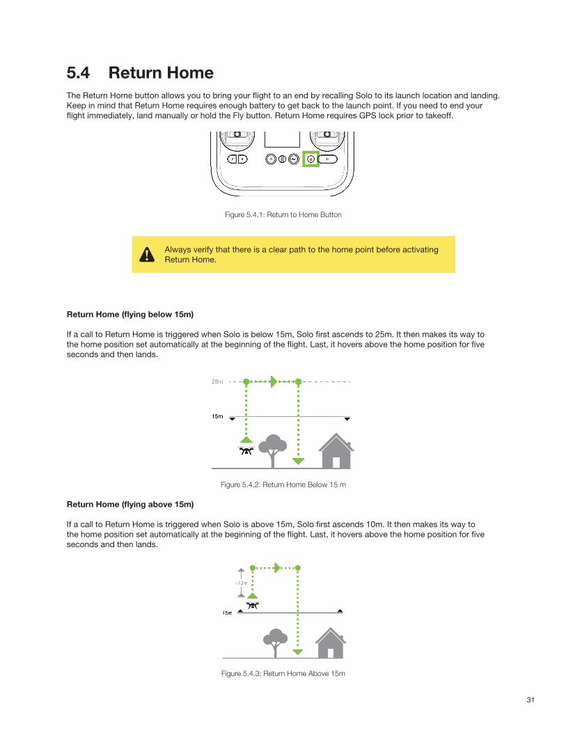
5.4 Return HomeThe Return Home button allows you to bring your flight to an end by recalling Solo to its launch location and landing. Keep in mind that Return Home requires enough battery to get back to the launch point. If you need to end your flight immediately, land manually or hold the Fly button. Return Home requires GPS lock prior to takeoff.
Figure 5.4.1: Return to Home Button
Return Home (flying below 15m)
If a call to Return Home is triggered when Solo is below 15m, Solo first ascends to 25m. It then makes its way to the home position set automatically at the beginning of the flight. Last, it hovers above the home position for five seconds and then lands.
Figure 5.4.2: Return Home Below 15 m
Return Home (flying above 15m)
If a call to Return Home is triggered when Solo is above 15m, Solo first ascends 10m. It then makes its way to the home position set automatically at the beginning of the flight. Last, it hovers above the home position for five seconds and then lands.
Figure 5.4.3: Return Home Above 15m
Always verify that there is a clear path to the home point before activating Return Home.

32
5.5 In-Flight DataUse the controller’s main data display to monitor Solo’s status in flight.
Figure 5.5.1: Controller - In-Flight Data
1 Flight battery percentage remaining 2 GPS signal strength and number of active satellites3 Active mode or Smart Shot (“Fly” indicates standard flight.)4 Controller battery level 5 Solo Wi-Fi signal strength6 Horizontal distance from the home position (launch point)7 Current altitude8 Currently assigned functions of controller A and B buttons
2
3 4
5
6
7
8
1

33
5.6 Joystick ControlThe controller’s two joysticks allow you to navigate Solo in flight. The left stick controls Solo’s altitude and rotation.
Figure 5.6.1: Controller Left Joystick
To control Solo’s altitude and acceleration, move the left stick vertically.
Figure 5.6.2: Throttle Joystick Behaviors
UP
DOWN
ROTATELEFT
ROTATE RIGHT
Left Stick
Move the left stick back from center to decrease altitude.
Set the left stick to center to maintain the current altitude.
Left Stick
Set the left stick fully back to land once Solo is a few inches above the ground.
Left Stick
To take off and to gain altitude, move the left stick slightly past the center position.
Left Stick
34
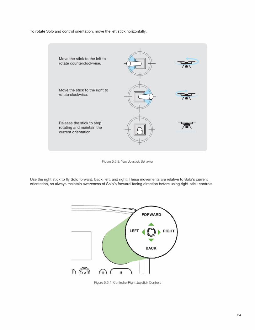
To rotate Solo and control orientation, move the left stick horizontally.
Figure 5.6.3: Yaw Joystick Behavior
Use the right stick to fly Solo forward, back, left, and right. These movements are relative to Solo’s current orientation, so always maintain awareness of Solo’s forward-facing direction before using right-stick controls.
Figure 5.6.4: Controller Right Joystick Controls
ActivateHold until propellers start spinning.
Take-off + LiftRaise just slightly for take off
Hover + LandLower just slightlyto hover
Left Yaw
Left
Back
Forward
Right
Right Yaw
DeactivateHold until propellersstop spinning
ActivateHold until propellers start spinning.
Take-off + LiftRaise just slightly for take off
Hover + LandLower just slightlyto hover
Left Yaw
Left
Back
Forward
Right
Right Yaw
DeactivateHold until propellersstop spinning
Move the stick to the left to rotate counterclockwise.
Move the stick to the right to rotate clockwise.
Left Stick
Release the stick to stop rotating and maintain the current orientation
LEFT RIGHT
FORWARD
BACK
35
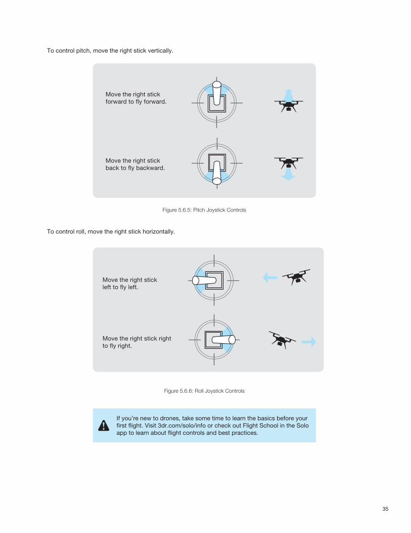
To control pitch, move the right stick vertically.
Figure 5.6.5: Pitch Joystick Controls
To control roll, move the right stick horizontally.
Figure 5.6.6: Roll Joystick Controls
ActivateHold until propellers start spinning.
Take-off + LiftRaise just slightly for take off
Hover + LandLower just slightlyto hover
Left Yaw
Left
Back
Forward
Right
Right Yaw
DeactivateHold until propellersstop spinning
ActivateHold until propellers start spinning.
Take-off + LiftRaise just slightly for take off
Hover + LandLower just slightlyto hover
Left Yaw
Left
Back
Forward
Right
Right Yaw
DeactivateHold until propellersstop spinning
Move the right stick forward to fly forward.
Move the right stick back to fly backward.
ActivateHold until propellers start spinning.
Take-off + LiftRaise just slightly for take off
Hover + LandLower just slightlyto hover
Left Yaw
Left
Back
Forward
Right
Right Yaw
DeactivateHold until propellersstop spinning
ActivateHold until propellers start spinning.
Take-off + LiftRaise just slightly for take off
Hover + LandLower just slightlyto hover
Left Yaw
Left
Back
Forward
Right
Right Yaw
DeactivateHold until propellersstop spinning
Move the right stick left to fly left.
Move the right stick right to fly right.
If you’re new to drones, take some time to learn the basics before your first flight. Visit 3dr.com/solo/info or check out Flight School in the Solo app to learn about flight controls and best practices.

36
5.7 App Interface OverviewThe Solo app provides a simplified interface for viewing Solo’s video feed and managing Smart Shots.
Figure 5.7.1: App - Main Interface
1 Live video feed 2 Main menu 3 Horizontal distance from home 4 Altitude 5 Shot List 6 Flight battery percentage remaining 7 Controller signal strength 8 Hide telemetry bar 9 Map view10 Start/stop recording to mobile device (requires Solo Gimbal)11 Alerts and instructions
5.7.1 Map View
To access the small map view, swipe left from the right edge of the app. To full-screen the map, swipe left again. To hide the map, tap the video display. The map view is available only with GPS lock and on devices with cellular Internet.
5.7.2 Shot List
To access the Shot List, select the active mode or shot from the title bar. To start a shot, choose from Selfie, Cable Cam, Orbit, and Follow, or for standard flight, choose Fly.
Figure 5.7.2.1: App - Shot List
2 4 6 7 83 5
1
9
11
110
37
6 Smart ShotsSolo’s Smart Shots automate video capturing to make it easy to get stunning aerial video. By default, Cable Cam and Orbit are assigned to the controller’s A and B buttons. Use the app to access Selfie or Follow. Smart Shots are available only with the Solo app.
When using Smart Shots without a Solo Gimbal, Solo cannot ensure that the subject is in the frame at all times. If this is the case, you can improve the chances of keeping the subject in the frame by adjusting the camera mount so the camera is fixed at an appropriate angle.
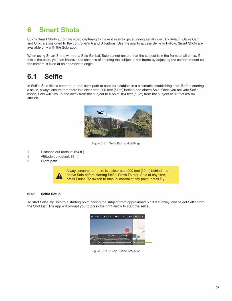
6.1 SelfieIn Selfie, Solo flies a smooth up-and-back path to capture a subject in a cinematic establishing shot. Before starting a selfie, always ensure that there is a clear path 200 feet (61 m) behind and above Solo. Once you activate Selfie mode, Solo will flies up and away from the subject to a point 164 feet (50 m) from the subject at 82 feet (25 m) altitude.
Figure 6.1.1: Selfie Path and Settings
1 Distance out (default 164 ft.)2 Altitude up (default 82 ft.)3 Flight path
6.1.1 Selfie Setup
To start Selfie, fly Solo to a starting point, facing the subject from approximately 10 feet away, and select Selfie from the Shot List. The app will prompt you to press the right arrow to start the selfie.
Figure 6.1.1.1: App - Selfie Activation
2
1
3
Always ensure that there is a clear path 200 feet (30 m) behind and above Solo before starting Selfie. Press To stop Solo at any time, press Pause. To switch to manual control at any point, press Fly.
38
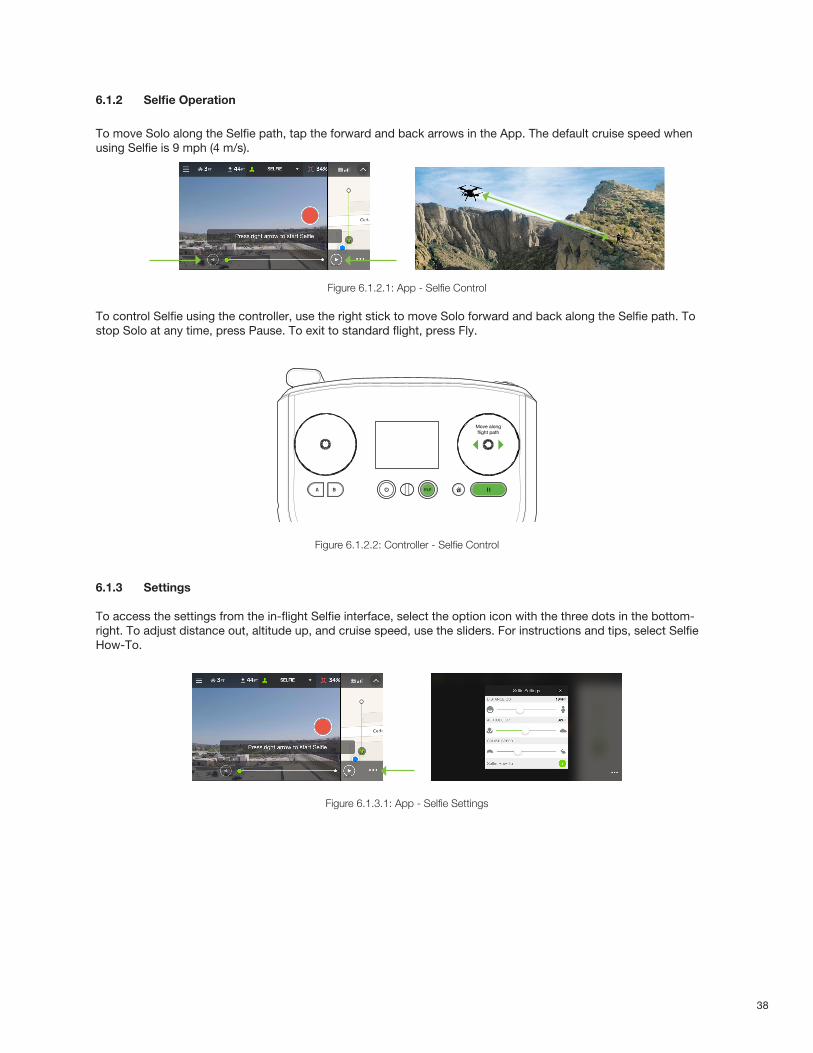
6.1.2 Selfie Operation
To move Solo along the Selfie path, tap the forward and back arrows in the App. The default cruise speed when using Selfie is 9 mph (4 m/s).
Figure 6.1.2.1: App - Selfie Control
To control Selfie using the controller, use the right stick to move Solo forward and back along the Selfie path. To stop Solo at any time, press Pause. To exit to standard flight, press Fly.
Figure 6.1.2.2: Controller - Selfie Control
6.1.3 Settings To access the settings from the in-flight Selfie interface, select the option icon with the three dots in the bottom-right. To adjust distance out, altitude up, and cruise speed, use the sliders. For instructions and tips, select Selfie How-To.
Figure 6.1.3.1: App - Selfie Settings
Move along flight path
39
6.2 Cable CamCable Cam creates a smooth shot by flying Solo along an imaginary cable between any two points that you specify initially.
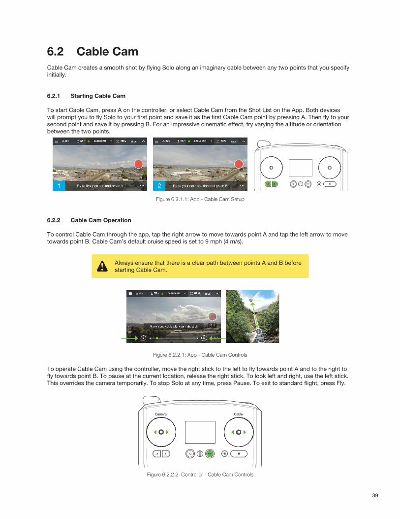
6.2.1 Starting Cable Cam
To start Cable Cam, press A on the controller, or select Cable Cam from the Shot List on the App. Both devices will prompt you to fly Solo to your first point and save it as the first Cable Cam point by pressing A. Then fly to your second point and save it by pressing B. For an impressive cinematic effect, try varying the altitude or orientation between the two points.
Figure 6.2.1.1: App - Cable Cam Setup
6.2.2 Cable Cam Operation
To control Cable Cam through the app, tap the right arrow to move towards point A and tap the left arrow to move towards point B. Cable Cam’s default cruise speed is set to 9 mph (4 m/s).
Figure 6.2.2.1: App - Cable Cam Controls
To operate Cable Cam using the controller, move the right stick to the left to fly towards point A and to the right to fly towards point B. To pause at the current location, release the right stick. To look left and right, use the left stick. This overrides the camera temporarily. To stop Solo at any time, press Pause. To exit to standard flight, press Fly.
Figure 6.2.2.2: Controller - Cable Cam Controls
Always ensure that there is a clear path between points A and B before starting Cable Cam.
Camera Cable
40
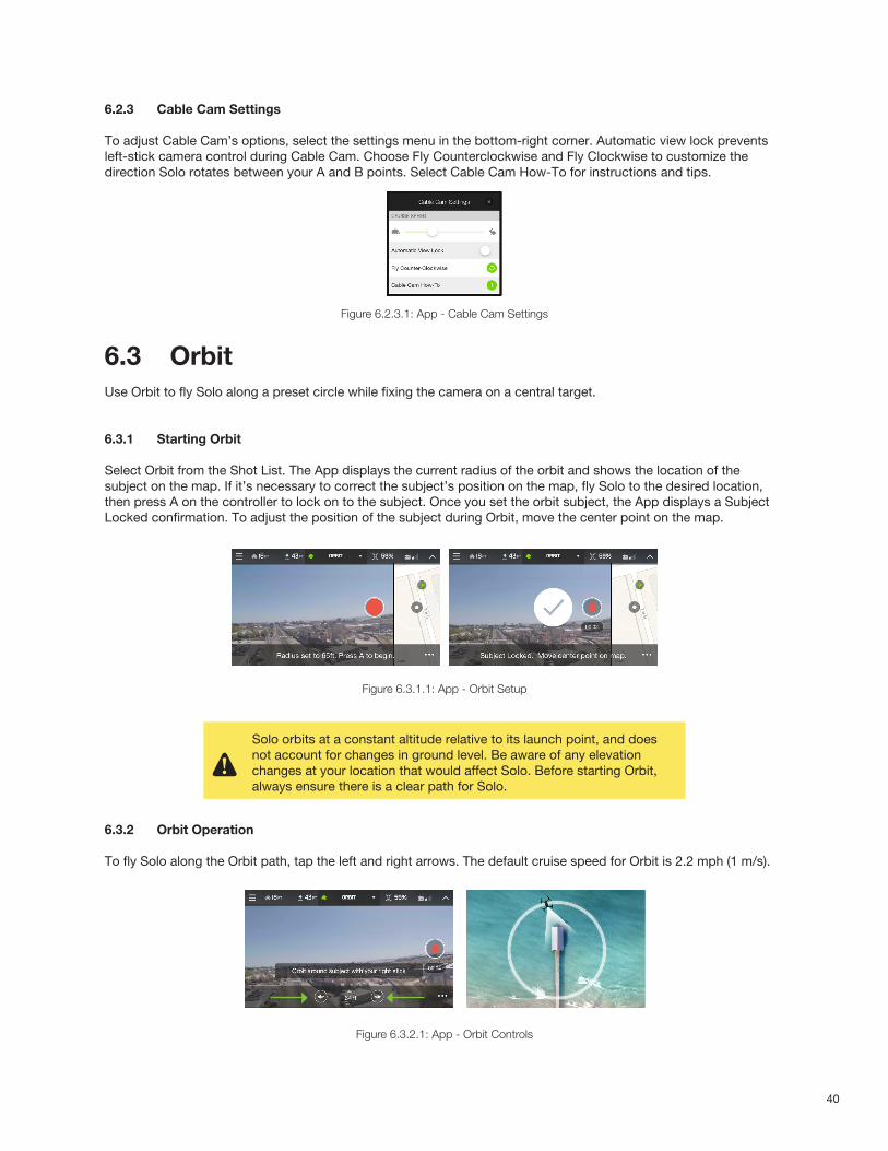
6.2.3 Cable Cam Settings
To adjust Cable Cam’s options, select the settings menu in the bottom-right corner. Automatic view lock prevents left-stick camera control during Cable Cam. Choose Fly Counterclockwise and Fly Clockwise to customize the direction Solo rotates between your A and B points. Select Cable Cam How-To for instructions and tips.
Figure 6.2.3.1: App - Cable Cam Settings
6.3 OrbitUse Orbit to fly Solo along a preset circle while fixing the camera on a central target.
6.3.1 Starting Orbit
Select Orbit from the Shot List. The App displays the current radius of the orbit and shows the location of the subject on the map. If it’s necessary to correct the subject’s position on the map, fly Solo to the desired location, then press A on the controller to lock on to the subject. Once you set the orbit subject, the App displays a Subject Locked confirmation. To adjust the position of the subject during Orbit, move the center point on the map.
Figure 6.3.1.1: App - Orbit Setup
6.3.2 Orbit Operation
To fly Solo along the Orbit path, tap the left and right arrows. The default cruise speed for Orbit is 2.2 mph (1 m/s).
Figure 6.3.2.1: App - Orbit Controls
Solo orbits at a constant altitude relative to its launch point, and does not account for changes in ground level. Be aware of any elevation changes at your location that would affect Solo. Before starting Orbit, always ensure there is a clear path for Solo.
41
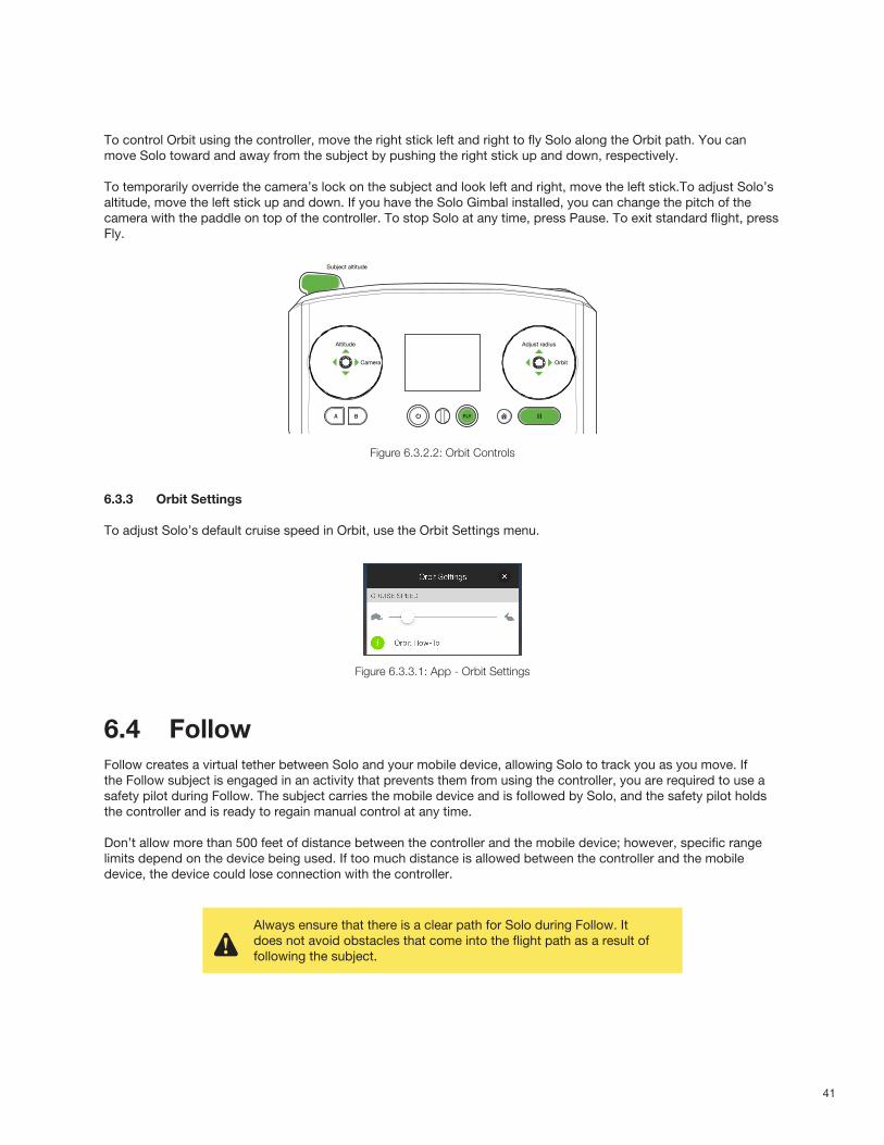
To control Orbit using the controller, move the right stick left and right to fly Solo along the Orbit path. You can move Solo toward and away from the subject by pushing the right stick up and down, respectively.
To temporarily override the camera’s lock on the subject and look left and right, move the left stick.To adjust Solo’s altitude, move the left stick up and down. If you have the Solo Gimbal installed, you can change the pitch of the camera with the paddle on top of the controller. To stop Solo at any time, press Pause. To exit standard flight, press Fly.
Figure 6.3.2.2: Orbit Controls
6.3.3 Orbit Settings
To adjust Solo’s default cruise speed in Orbit, use the Orbit Settings menu.
Figure 6.3.3.1: App - Orbit Settings
6.4 FollowFollow creates a virtual tether between Solo and your mobile device, allowing Solo to track you as you move. If the Follow subject is engaged in an activity that prevents them from using the controller, you are required to use a safety pilot during Follow. The subject carries the mobile device and is followed by Solo, and the safety pilot holds the controller and is ready to regain manual control at any time.
Don’t allow more than 500 feet of distance between the controller and the mobile device; however, specific range limits depend on the device being used. If too much distance is allowed between the controller and the mobile device, the device could lose connection with the controller.
Orbit
Adjust radiusAltitude
Camera
Subject altitude
Always ensure that there is a clear path for Solo during Follow. It does not avoid obstacles that come into the flight path as a result of following the subject.
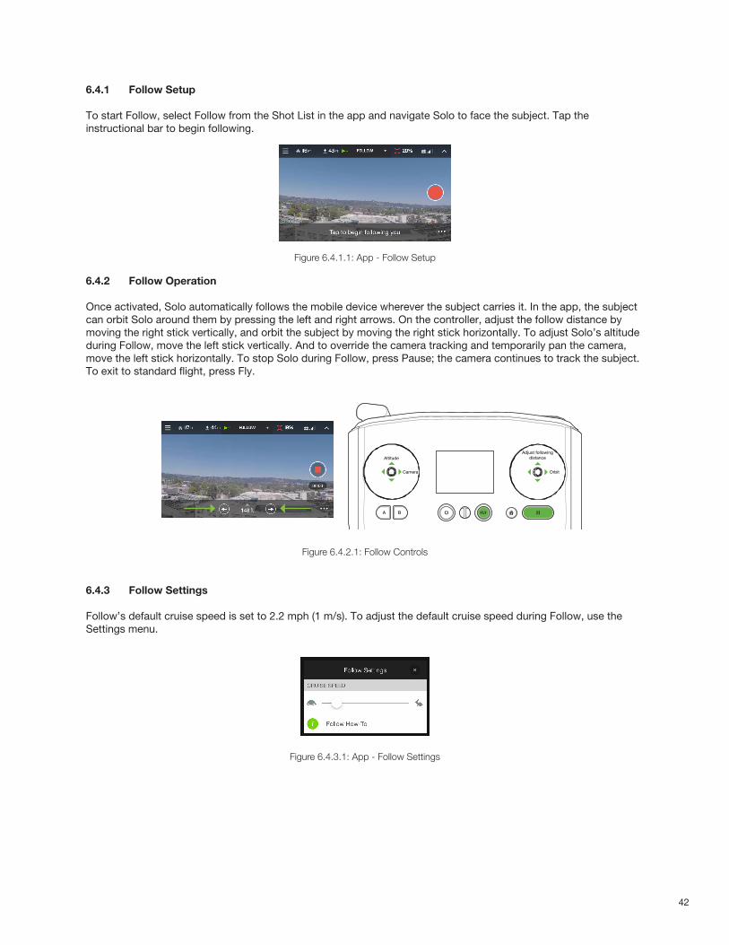
42
6.4.1 Follow Setup
To start Follow, select Follow from the Shot List in the app and navigate Solo to face the subject. Tap the instructional bar to begin following.
Figure 6.4.1.1: App - Follow Setup
6.4.2 Follow Operation
Once activated, Solo automatically follows the mobile device wherever the subject carries it. In the app, the subject can orbit Solo around them by pressing the left and right arrows. On the controller, adjust the follow distance by moving the right stick vertically, and orbit the subject by moving the right stick horizontally. To adjust Solo’s altitude during Follow, move the left stick vertically. And to override the camera tracking and temporarily pan the camera, move the left stick horizontally. To stop Solo during Follow, press Pause; the camera continues to track the subject. To exit to standard flight, press Fly.
Figure 6.4.2.1: Follow Controls
6.4.3 Follow Settings
Follow’s default cruise speed is set to 2.2 mph (1 m/s). To adjust the default cruise speed during Follow, use the Settings menu.
Figure 6.4.3.1: App - Follow Settings
Orbit
Adjust following distanceAltitude
Camera
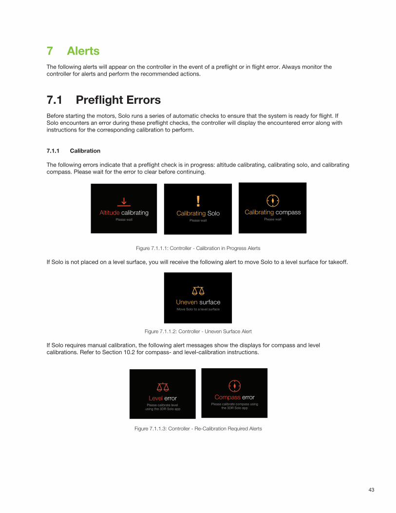
43
7 AlertsThe following alerts will appear on the controller in the event of a preflight or in flight error. Always monitor the controller for alerts and perform the recommended actions.
7.1 Preflight ErrorsBefore starting the motors, Solo runs a series of automatic checks to ensure that the system is ready for flight. If Solo encounters an error during these preflight checks, the controller will display the encountered error along with instructions for the corresponding calibration to perform.
7.1.1 Calibration
The following errors indicate that a preflight check is in progress: altitude calibrating, calibrating solo, and calibrating compass. Please wait for the error to clear before continuing.
Figure 7.1.1.1: Controller - Calibration in Progress Alerts
If Solo is not placed on a level surface, you will receive the following alert to move Solo to a level surface for takeoff.
Figure 7.1.1.2: Controller - Uneven Surface Alert
If Solo requires manual calibration, the following alert messages show the displays for compass and level calibrations. Refer to Section 10.2 for compass- and level-calibration instructions.
Figure 7.1.1.3: Controller - Re-Calibration Required Alerts
PREARM SENSOR ERRORS
Altitude calibrationSystem self-calibrates altitude after altitude disparity
Alert persists until:
System self-calibrates (sys then continues sensor check)
Timeout: after 1 minute (?) (results in “sensor error” screen)
Altitude calibratingPlease wait
Compass errorUser asked to use Solo app to calibrate.
Alert persists until:
User completes calibration using the app (sys then continues sensor check)
Powers off controller, or Solo
Controller auto-shutdown
Note: Artoo will not assume the same error is present on restart, and will run a fresh check when connected to Solo.
Compass errorPlease calibrate compass using
the 3DR Solo app
Level errorUser is asked to use Solo app to calibrate
Alert persists until:
User complete calibration using the app (sys then continues sensor check)
Powers off controller, or Solo
Controller auto-shutdown
Note: Artoo will not assume the same error is present on restart, and will run a fresh check when connected to Solo.
Level errorPlease calibrate level
using the 3DR Solo app
Sensor error screenFor sensor errors requiring user-initiated restart
Sensor errorPlease try and restart Solo
Battery unknownDisplayed if Artoo is powered on with a battery has an ID resistor unknown to Artoo. (Not logged in current software version’s index.)
HAPTIC: Strong feedback, 40 millisecond pulse
After Solo is disconnected, Artoo should display “waiting for Solo”
Unknown batteryBattery % not be accurate
?
Dismiss
Control sticl error
Persists until:
Controller starts with stick values in range.
Control stick errorContact 3DR customer support
ARMING ALERTS
Altitude calibrationSystem self-calibrates altitude after altitude disparity
Alert persists until:
System self-calibrates (sys then continues sensor check)
Timeout: after 1 minute (?) (results in “sensor error” screen)
Calibration errorPlease restart Solo
Compass errorUser is asked to use Solo app to calibrate.
Alert persists until:
User completes calibration using the app (system then continues sensor check)
User powers off controller, or Solo
Controller auto-shutdown
Note: Artoo will not assume the same error is present on restart, and will run a fresh check when connected to Solo.
Calibrating compassPlease wait
Level errorUser is asked to use Solo app to calibrate
Alert persists until:
User complete calibration using the app (sys then continues sensor check)
Powers off controller, or Solo
Controller auto-shutdown
Note: Artoo will not assume the same error is present on restart, and will run a fresh check when connected to Solo.
Uneven surfaceMove Solo to a level surface
Altitude calibrationSystem self-calibrates altitude after altitude disparity
Alert persists until:
System self-calibrates (sys then continues sensor check)
Timeout: after 1 minute (?) (results in “sensor error” screen)
Calibrating SoloPlease wait
Compass errorUser asked to use Solo app to calibrate.
Alert persists until:
User completes calibration using the app (sys then continues sensor check)
Powers off controller, or Solo
Controller auto-shutdown
Note: Artoo will not assume the same error is present on restart, and will run a fresh check when connected to Solo.
Throttle too highThis flight mode requires low throttle before starting motors
Catch-All
Remaining rare but problematic APM errorswill be captured under a catch-all forlogging trouble tickets
Service requiredUse 3DR Solo app to log a trouble
ticket with customer support
PREARM SENSOR ERRORS
Altitude calibrationSystem self-calibrates altitude after altitude disparity
Alert persists until:
System self-calibrates (sys then continues sensor check)
Timeout: after 1 minute (?) (results in “sensor error” screen)
Altitude calibratingPlease wait
Compass errorUser asked to use Solo app to calibrate.
Alert persists until:
User completes calibration using the app (sys then continues sensor check)
Powers off controller, or Solo
Controller auto-shutdown
Note: Artoo will not assume the same error is present on restart, and will run a fresh check when connected to Solo.
Compass errorPlease calibrate compass using
the 3DR Solo app
Level errorUser is asked to use Solo app to calibrate
Alert persists until:
User complete calibration using the app (sys then continues sensor check)
Powers off controller, or Solo
Controller auto-shutdown
Note: Artoo will not assume the same error is present on restart, and will run a fresh check when connected to Solo.
Level errorPlease calibrate level
using the 3DR Solo app
Sensor error screenFor sensor errors requiring user-initiated restart
Sensor errorPlease try and restart Solo
Battery unknownDisplayed if Artoo is powered on with a battery has an ID resistor unknown to Artoo. (Not logged in current software version’s index.)
HAPTIC: Strong feedback, 40 millisecond pulse
After Solo is disconnected, Artoo should display “waiting for Solo”
Unknown batteryBattery % not be accurate
?
Dismiss
Control sticl error
Persists until:
Controller starts with stick values in range.
Control stick errorContact 3DR customer support
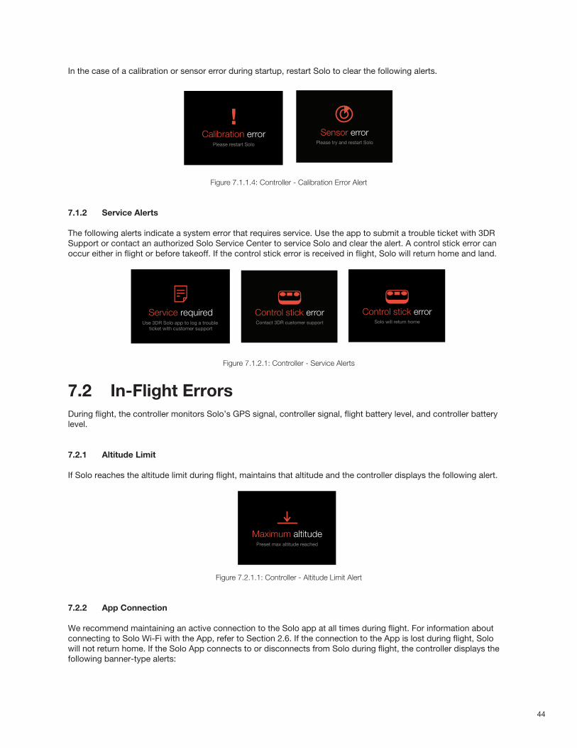
44
In the case of a calibration or sensor error during startup, restart Solo to clear the following alerts.
Figure 7.1.1.4: Controller - Calibration Error Alert
7.1.2 Service Alerts
The following alerts indicate a system error that requires service. Use the app to submit a trouble ticket with 3DR Support or contact an authorized Solo Service Center to service Solo and clear the alert. A control stick error can occur either in flight or before takeoff. If the control stick error is received in flight, Solo will return home and land.
Figure 7.1.2.1: Controller - Service Alerts
7.2 In-Flight ErrorsDuring flight, the controller monitors Solo’s GPS signal, controller signal, flight battery level, and controller battery level.
7.2.1 Altitude Limit
If Solo reaches the altitude limit during flight, maintains that altitude and the controller displays the following alert.
Figure 7.2.1.1: Controller - Altitude Limit Alert
7.2.2 App Connection
We recommend maintaining an active connection to the Solo app at all times during flight. For information about connecting to Solo Wi-Fi with the App, refer to Section 2.6. If the connection to the App is lost during flight, Solo will not return home. If the Solo App connects to or disconnects from Solo during flight, the controller displays the following banner-type alerts:
ARMING ALERTS
Altitude calibrationSystem self-calibrates altitude after altitude disparity
Alert persists until:
System self-calibrates (sys then continues sensor check)
Timeout: after 1 minute (?) (results in “sensor error” screen)
Calibration errorPlease restart Solo
Compass errorUser is asked to use Solo app to calibrate.
Alert persists until:
User completes calibration using the app (system then continues sensor check)
User powers off controller, or Solo
Controller auto-shutdown
Note: Artoo will not assume the same error is present on restart, and will run a fresh check when connected to Solo.
Calibrating compassPlease wait
Level errorUser is asked to use Solo app to calibrate
Alert persists until:
User complete calibration using the app (sys then continues sensor check)
Powers off controller, or Solo
Controller auto-shutdown
Note: Artoo will not assume the same error is present on restart, and will run a fresh check when connected to Solo.
Uneven surfaceMove Solo to a level surface
Altitude calibrationSystem self-calibrates altitude after altitude disparity
Alert persists until:
System self-calibrates (sys then continues sensor check)
Timeout: after 1 minute (?) (results in “sensor error” screen)
Calibrating SoloPlease wait
Compass errorUser asked to use Solo app to calibrate.
Alert persists until:
User completes calibration using the app (sys then continues sensor check)
Powers off controller, or Solo
Controller auto-shutdown
Note: Artoo will not assume the same error is present on restart, and will run a fresh check when connected to Solo.
Throttle too highThis flight mode requires low throttle before starting motors
Catch-All
Remaining rare but problematic APM errorswill be captured under a catch-all forlogging trouble tickets
Service requiredUse 3DR Solo app to log a trouble
ticket with customer support
PREARM SENSOR ERRORS
Altitude calibrationSystem self-calibrates altitude after altitude disparity
Alert persists until:
System self-calibrates (sys then continues sensor check)
Timeout: after 1 minute (?) (results in “sensor error” screen)
Altitude calibratingPlease wait
Compass errorUser asked to use Solo app to calibrate.
Alert persists until:
User completes calibration using the app (sys then continues sensor check)
Powers off controller, or Solo
Controller auto-shutdown
Note: Artoo will not assume the same error is present on restart, and will run a fresh check when connected to Solo.
Compass errorPlease calibrate compass using
the 3DR Solo app
Level errorUser is asked to use Solo app to calibrate
Alert persists until:
User complete calibration using the app (sys then continues sensor check)
Powers off controller, or Solo
Controller auto-shutdown
Note: Artoo will not assume the same error is present on restart, and will run a fresh check when connected to Solo.
Level errorPlease calibrate level
using the 3DR Solo app
Sensor error screenFor sensor errors requiring user-initiated restart
Sensor errorPlease try and restart Solo
Battery unknownDisplayed if Artoo is powered on with a battery has an ID resistor unknown to Artoo. (Not logged in current software version’s index.)
HAPTIC: Strong feedback, 40 millisecond pulse
After Solo is disconnected, Artoo should display “waiting for Solo”
Unknown batteryBattery % not be accurate
?
Dismiss
Control sticl error
Persists until:
Controller starts with stick values in range.
Control stick errorContact 3DR customer support
IN-FLIGHT ALERTS: CONTROLLER RELATED
RC FailsafeController signal lost, RTH screen
Alert persists until:
TIMEOUT: 5000 milliseconds
Controller signal lost
Solo will return home
RC Signal RecoveredUser can press Fly to recover
Alert persists until:
User presses Fly and enters Fly mode
HAPTIC: 40millisecond so user is aware that they can take control
RC Failsafe (No GPS)Controller signal lost, emergency land screen
Alert persists until:
TIMEOUT: 5000 milliseconds
Controller Value out of Range User is asked to contact customer support
Alert persists until:
TIMEOUT: 5000 milliseconds
go to persistent hint-box message
(persistent until reboot)
Control stick errorSolo will return home
Signal recovered
Controller signal lostEmergency landing started
324FT
84FT
HOME
48%
FLIGHT BATTERY
ALTITUDE
Return Home12
Control stick errorContact 3DR Support after landing
Camera paddle and dial failure
Alert triggered on input error on the paddle or tilt speed dial potentiometers
TIMEOUT: 5000 milliseconds
Control stick errorSolo will return home
324FT
84FT
HOME
48%
FLIGHT BATTERY
ALTITUDE
FLY12
Manual camera controls error
IN-FLIGHT ALERTS
Maximum AltitudeUser is told that maximum altitude has been reached
Vehicle is not able to go higher than max altitude
Alert appears once per flight and is triggered at 100 FT by default.
Alert persists until:
TIMEOUT: 5000 milliseconds
HAPTIC: Double buzz 40-40 millisecond
Maximum altitudePreset max altitude reached
Crash DetectedUser can use app to log a support ticket
Alert persists until:
User presses A
HAPTIC: Quad buzz: 40-40-40-40
Solo SFX: Start lost call ping if more than 10 m away
Crash detected
GPS signal lost (Switches to FLY: Manual)
Alert persists until:
TIMEOUT: 3000 milliseconds
HAPTIC: Triple buzz twice: 30-30-30, 30-30-30
GPS lostSwitching to manual control
GPS signal recovered (User who has either advanced mode enabled, or manual set to A or B)
(When home is already set)
Switches to FLY form Fly:Manual when user presses Fly
Alert persists until:
TIMEOUT: 3000 milliseconds
GPS ready
Press to dismiss
FLYPress for GPS control
GPS signal recovered (No advanced mode, Manual mode not set to A or B) Switches to FLY when GPS is recovered
Alert persists until:
TIMEOUT: 3000 milliseconds
HAPTIC: 40 millisecond buzz for awareness
GPS ready
GPS signal established(User took off without GPS, no home position, regardless of advanced modes)
Alert persists until user sets home
HAPTIC: 20 milliseconds every 3 seconds until press
GPS found
FLYPress to set home
Switching to FLY
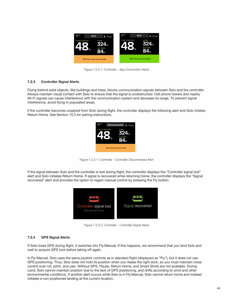
45
Figure 7.2.2.1: Controller - App Connection Alerts
7.2.3 Controller Signal Alerts
Flying behind solid objects, like buildings and trees, blocks communication signals between Solo and the controller. Always maintain visual contact with Solo to ensure that the signal is unobstructed. Cell phone towers and nearby Wi-Fi signals can cause interference with the communication system and decrease its range. To prevent signal interference, avoid flying in populated areas.
If the controller becomes unpaired from Solo during flight, the controller displays the following alert and Solo initates Return Home. See Section 10.3 for pairing instructions.
Figure 7.2.3.1: Controller - Controller Disconnected Alert
If the signal between Solo and the controller is lost during flight, the controller displays the “Controller signal lost” alert and Solo initiates Return Home. If signal is recovered while returning home, the controller displays the “Signal recovered” alert and provides the option to regain manual control by pressing the Fly button.
Figure 7.2.3.2: Controller - Controller Signal Alerts
7.2.4 GPS Signal Alerts
If Solo loses GPS during flight, it switches into Fly:Manual. If this happens, we recommend that you land Solo and wait to acquire GPS lock before taking off again.
In Fly:Manual, Solo uses the same joystick controls as in standard flight (displayed as “Fly”), but it does not use GPS positioning. Thus, Solo does not hold its position when you rlease the right stick, so you must maintain close control over roll, pitch, and yaw. Without GPS, Pause, Return Home, and Smart Shots are not available. During Land, Solo cannot maintain position due to the lack of GPS positioning, and drifts according to wind and other environmental conditions. If another alert occurs while Solo is in Fly:Manual, Solo cannot return home and instead initiates a non-positioned landing at the current location.
IN-FLIGHT BANNER ALERTS
Solo app connected (Banner)System self-calibrates altitude after altitude disparity
Alert persists until:
System self-calibrates (sys then continues sensor check)
Timeout: after 1 minute (?) (results in “sensor error” screen)
Solo app disconnected (Banner)System self-calibrates altitude after altitude disparity
Alert persists until:
System self-calibrates (sys then continues sensor check)
Timeout: after 1 minute (?) (results in “sensor error” screen)
Landing CompleteScreen showing automatic landing is complete
Alert persists until:
TIMEOUT: 3000 milliseconds
Controller connection poor (Banner)
Appears once connection strength is below average performancefor X time.
TIMEOUT: After 3000 milliseconds
324FT
84FT
HOME
48%
FLIGHT BATTERY
ALTITUDE
FLY12
3DR Solo app connected
324FT
84FT
HOME
48%
FLIGHT BATTERY
ALTITUDE
FLY12
3DR Solo app disconnected
324FT
84FT
HOME
48%
FLIGHT BATTERY
ALTITUDE
FLY12
Landing complete
324FT
84FT
HOME
48%
FLIGHT BATTERY
ALTITUDE
Disconnected12
Disconnected from Solo
IN-FLIGHT ALERTS: CONTROLLER RELATED
RC FailsafeController signal lost, RTH screen
Alert persists until:
TIMEOUT: 5000 milliseconds
Controller signal lost
Solo will return home
RC Signal RecoveredUser can press Fly to recover
Alert persists until:
User presses Fly and enters Fly mode
HAPTIC: 40millisecond so user is aware that they can take control
RC Failsafe (No GPS)Controller signal lost, emergency land screen
Alert persists until:
TIMEOUT: 5000 milliseconds
Controller Value out of Range User is asked to contact customer support
Alert persists until:
TIMEOUT: 5000 milliseconds
go to persistent hint-box message
(persistent until reboot)
Control stick errorSolo will return home
Signal recovered
Controller signal lostEmergency landing started
324FT
84FT
HOME
48%
FLIGHT BATTERY
ALTITUDE
Return Home12
Control stick errorContact 3DR Support after landing
Camera paddle and dial failure
Alert triggered on input error on the paddle or tilt speed dial potentiometers
TIMEOUT: 5000 milliseconds
Control stick errorSolo will return home
324FT
84FT
HOME
48%
FLIGHT BATTERY
ALTITUDE
FLY12
Manual camera controls error
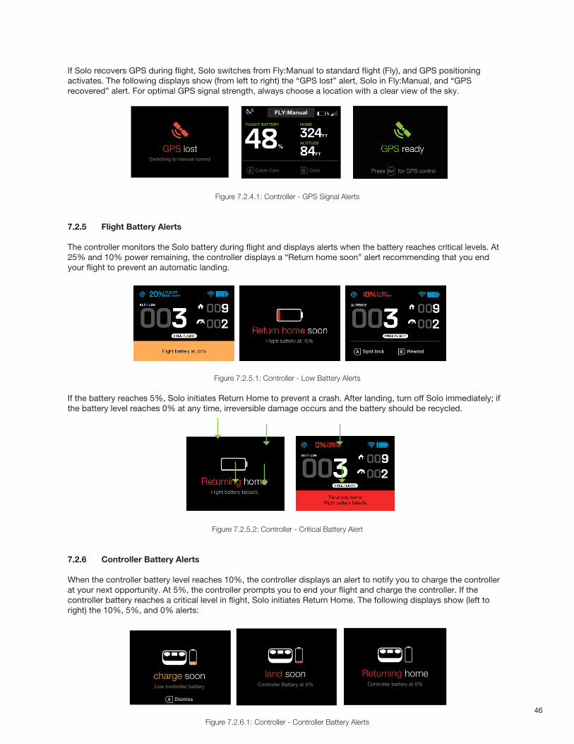
46
If Solo recovers GPS during flight, Solo switches from Fly:Manual to standard flight (Fly), and GPS positioning activates. The following displays show (from left to right) the “GPS lost” alert, Solo in Fly:Manual, and “GPS recovered” alert. For optimal GPS signal strength, always choose a location with a clear view of the sky.
Figure 7.2.4.1: Controller - GPS Signal Alerts
7.2.5 Flight Battery Alerts
The controller monitors the Solo battery during flight and displays alerts when the battery reaches critical levels. At 25% and 10% power remaining, the controller displays a “Return home soon” alert recommending that you end your flight to prevent an automatic landing.
Figure 7.2.5.1: Controller - Low Battery Alerts
If the battery reaches 5%, Solo initiates Return Home to prevent a crash. After landing, turn off Solo immediately; if the battery level reaches 0% at any time, irreversible damage occurs and the battery should be recycled.
Figure 7.2.5.2: Controller - Critical Battery Alert
7.2.6 Controller Battery Alerts
When the controller battery level reaches 10%, the controller displays an alert to notify you to charge the controller at your next opportunity. At 5%, the controller prompts you to end your flight and charge the controller. If the controller battery reaches a critical level in flight, Solo initiates Return Home. The following displays show (left to right) the 10%, 5%, and 0% alerts:
Figure 7.2.6.1: Controller - Controller Battery Alerts
IN-FLIGHT ALERTS
Maximum AltitudeUser is told that maximum altitude has been reached
Vehicle is not able to go higher than max altitude
Alert appears once per flight and is triggered at 100 FT by default.
Alert persists until:
TIMEOUT: 5000 milliseconds
HAPTIC: Double buzz 40-40 millisecond
Maximum altitudePreset max altitude reached
Crash DetectedUser can use app to log a support ticket
Alert persists until:
User presses A
HAPTIC: Quad buzz: 40-40-40-40
Solo SFX: Start lost call ping if more than 10 m away
Crash detected
GPS signal lost (Switches to FLY: Manual)
Alert persists until:
TIMEOUT: 3000 milliseconds
HAPTIC: Triple buzz twice: 30-30-30, 30-30-30
GPS lostSwitching to manual control
GPS signal recovered (User who has either advanced mode enabled, or manual set to A or B)
(When home is already set)
Switches to FLY form Fly:Manual when user presses Fly
Alert persists until:
TIMEOUT: 3000 milliseconds
GPS ready
Press to dismiss
FLYPress for GPS control
GPS signal recovered (No advanced mode, Manual mode not set to A or B) Switches to FLY when GPS is recovered
Alert persists until:
TIMEOUT: 3000 milliseconds
HAPTIC: 40 millisecond buzz for awareness
GPS ready
GPS signal established(User took off without GPS, no home position, regardless of advanced modes)
Alert persists until user sets home
HAPTIC: 20 milliseconds every 3 seconds until press
GPS found
FLYPress to set home
Switching to FLY
Emergency mode changeGPS lock is lost, Solo automatically enters Alt. hold
Fullscreen message
Times out after 5000 milliseconds
Modified Telem screen (Version 1)Now shows new mode. A & B functions that require GPS are greyed out.
IN-FLIGHT WARNINGS
GPS Lost
GPS lostSwitching to manual control
Cable Cam Orbit
324FT
84FT
HOME
48%
FLIGHT BATTERY
ALTITUDE
FLY6
Cable Cam Orbit
324FT
84FT
HOME
48%
FLIGHT BATTERY
ALTITUDE
FLY:Manual6
Cable Cam Orbit
324FT
84FT
HOME
48%
FLIGHT BATTERY
ALTITUDE
Stabilize12
CONTROLLER BATTERY WARNINGS + PROMPTS
Controller battery low Please land soon
Between 5% and 10% user is asked to charge soonMessage only appears when Solo is not in flight (pre-flight state, motors not started.)
Helps user catch low battery before flight.
Fullscreen prompt at 5%Message timeout after 3000 miliseconds. Go to previous screen + minimized prompt (continuous until landing.)
Slider message persistsBattery updates to red fill for 3%-5%
(Battery level now known in 3% chunks)
Good controller battery state
(If GPS Lock is not present)In-flight: At 0%, auto-land
Message present until controller shuts down
(If GPS Lock is present)In-flight: At 0%, Solo returns to home location
Message present until controller shuts down
Critically low flight battery (Prevented from flying)User is prevented from flying a battery lower than 5%.
charge soonLow controller battery
land soonController Battery at 5%
charge controllerBattery too low for flight
Returning homeController battery at 0%
Emergency-landingController Battery at 0%
Dismiss
Cable Cam Orbit
324FT
84FT
HOME
48%
FLIGHT BATTERY
ALTITUDE
Stabilize12
Cable Cam Orbit
324FT
84FT
HOME
48%
FLIGHT BATTERY
ALTITUDE
Stabilize12
CONTROLLER BATTERY WARNINGS + PROMPTS
Controller battery low Please land soon
Between 5% and 10% user is asked to charge soonMessage only appears when Solo is not in flight (pre-flight state, motors not started.)
Helps user catch low battery before flight.
Fullscreen prompt at 5%Message timeout after 3000 miliseconds. Go to previous screen + minimized prompt (continuous until landing.)
Slider message persistsBattery updates to red fill for 3%-5%
(Battery level now known in 3% chunks)
Good controller battery state
(If GPS Lock is not present)In-flight: At 0%, auto-land
Message present until controller shuts down
(If GPS Lock is present)In-flight: At 0%, Solo returns to home location
Message present until controller shuts down
Critically low flight battery (Prevented from flying)User is prevented from flying a battery lower than 5%.
charge soonLow controller battery
land soonController Battery at 5%
charge controllerBattery too low for flight
Returning homeController battery at 0%
Emergency-landingController Battery at 0%
Dismiss
Cable Cam Orbit
324FT
84FT
HOME
48%
FLIGHT BATTERY
ALTITUDE
Stabilize12
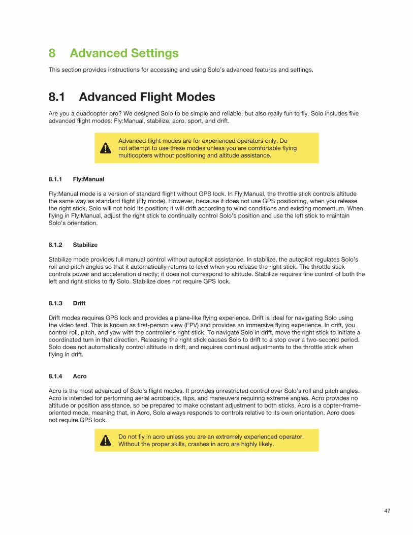
47
8 Advanced SettingsThis section provides instructions for accessing and using Solo’s advanced features and settings.
8.1 Advanced Flight ModesAre you a quadcopter pro? We designed Solo to be simple and reliable, but also really fun to fly. Solo includes five advanced flight modes: Fly:Manual, stabilize, acro, sport, and drift.
8.1.1 Fly:Manual
Fly:Manual mode is a version of standard flight without GPS lock. In Fly:Manual, the throttle stick controls altitude the same way as standard flight (Fly mode). However, because it does not use GPS positioning, when you release the right stick, Solo will not hold its position; it will drift according to wind conditions and existing momentum. When flying in Fly:Manual, adjust the right stick to continually control Solo’s position and use the left stick to maintain Solo’s orientation.
8.1.2 Stabilize
Stabilize mode provides full manual control without autopilot assistance. In stabilize, the autopilot regulates Solo’s roll and pitch angles so that it automatically returns to level when you release the right stick. The throttle stick controls power and acceleration directly; it does not correspond to altitude. Stabilize requires fine control of both the left and right sticks to fly Solo. Stabilize does not require GPS lock.
8.1.3 Drift
Drift modes requires GPS lock and provides a plane-like flying experience. Drift is ideal for navigating Solo using the video feed. This is known as first-person view (FPV) and provides an immersive flying experience. In drift, you control roll, pitch, and yaw with the controller’s right stick. To navigate Solo in drift, move the right stick to initiate a coordinated turn in that direction. Releasing the right stick causes Solo to drift to a stop over a two-second period. Solo does not automatically control altitude in drift, and requires continual adjustments to the throttle stick when flying in drift.
8.1.4 Acro
Acro is the most advanced of Solo’s flight modes. It provides unrestricted control over Solo’s roll and pitch angles. Acro is intended for performing aerial acrobatics, flips, and maneuvers requiring extreme angles. Acro provides no altitude or position assistance, so be prepared to make constant adjustment to both sticks. Acro is a copter-frame-oriented mode, meaning that, in Acro, Solo always responds to controls relative to its own orientation. Acro does not require GPS lock.
Advanced flight modes are for experienced operators only. Do not attempt to use these modes unless you are comfortable flying multicopters without positioning and altitude assistance.
Do not fly in acro unless you are an extremely experienced operator. Without the proper skills, crashes in acro are highly likely.
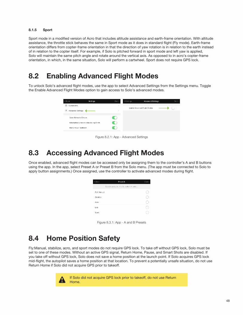
48
8.1.5 Sport
Sport mode in a modified version of Acro that includes altitude assistance and earth-frame orientation. With altitude assistance, the throttle stick behaves the same in Sport mode as it does in standard flight (Fly mode). Earth-frame orientation differs from copter-frame orientation in that the direction of yaw rotation is in relation to the earth instead of in relation to the copter itself. For example, if Solo is pitched forward in sport mode and left yaw is applied, Solo will maintain the same pitch angle and rotate around the vertical axis. As opposed to in acro’s copter-frame orientation, in which, in the same situation, Solo will perform a cartwheel. Sport does not require GPS lock.
8.2 Enabling Advanced Flight ModesTo unlock Solo’s advanced flight modes, use the app to select Advanced Settings from the Settings menu. Toggle the Enable Advanced Flight Modes option to gain access to Solo’s advanced modes.
Figure 8.2.1: App - Advanced Settings
8.3 Accessing Advanced Flight ModesOnce enabled, advanced flight modes can be accessed only be assigning them to the controller’s A and B buttons using the app. In the app, select Preset A or Preset B from the Solo menu. (The app must be connected to Solo to apply button assignments.) Once assigned, use the controller to activate advanced modes during flight.
Figure 8.3.1: App - A and B Presets
8.4 Home Position SafetyFly:Manual, stabilize, acro, and sport modes do not require GPS lock. To take off without GPS lock, Solo must be set to one of these modes. Without an active GPS signal, Return Home, Pause, and Smart Shots are disabled. If you take off without GPS lock, Solo does not save a home position at the launch point. If Solo acquires GPS lock mid-flight, the autopilot saves a home position at that location. To prevent a potentially unsafe situation, do not use Return Home if Solo did not acquire GPS prior to takeoff.
If Solo did not acquire GPS lock prior to takeoff, do not use Return Home.
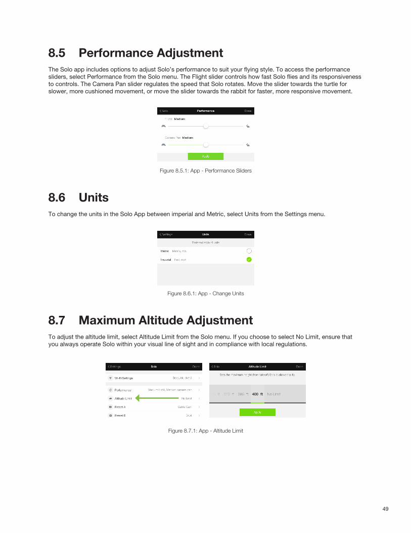
49
8.5 Performance AdjustmentThe Solo app includes options to adjust Solo’s performance to suit your flying style. To access the performance sliders, select Performance from the Solo menu. The Flight slider controls how fast Solo flies and its responsiveness to controls. The Camera Pan slider regulates the speed that Solo rotates. Move the slider towards the turtle for slower, more cushioned movement, or move the slider towards the rabbit for faster, more responsive movement.
Figure 8.5.1: App - Performance Sliders
8.6 UnitsTo change the units in the Solo App between imperial and Metric, select Units from the Settings menu.
Figure 8.6.1: App - Change Units
8.7 Maximum Altitude AdjustmentTo adjust the altitude limit, select Altitude Limit from the Solo menu. If you choose to select No Limit, ensure that you always operate Solo within your visual line of sight and in compliance with local regulations.
Figure 8.7.1: App - Altitude Limit
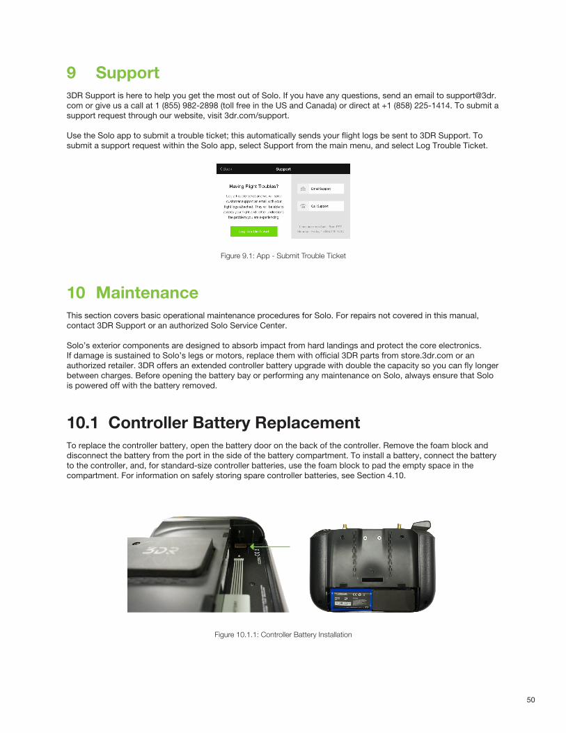
50
9 Support3DR Support is here to help you get the most out of Solo. If you have any questions, send an email to [email protected] or give us a call at 1 (855) 982-2898 (toll free in the US and Canada) or direct at +1 (858) 225-1414. To submit a support request through our website, visit 3dr.com/support.
Use the Solo app to submit a trouble ticket; this automatically sends your flight logs be sent to 3DR Support. To submit a support request within the Solo app, select Support from the main menu, and select Log Trouble Ticket.
Figure 9.1: App - Submit Trouble Ticket
10 MaintenanceThis section covers basic operational maintenance procedures for Solo. For repairs not covered in this manual, contact 3DR Support or an authorized Solo Service Center.
Solo’s exterior components are designed to absorb impact from hard landings and protect the core electronics. If damage is sustained to Solo’s legs or motors, replace them with official 3DR parts from store.3dr.com or an authorized retailer. 3DR offers an extended controller battery upgrade with double the capacity so you can fly longer between charges. Before opening the battery bay or performing any maintenance on Solo, always ensure that Solo is powered off with the battery removed.
10.1 Controller Battery ReplacementTo replace the controller battery, open the battery door on the back of the controller. Remove the foam block and disconnect the battery from the port in the side of the battery compartment. To install a battery, connect the battery to the controller, and, for standard-size controller batteries, use the foam block to pad the empty space in the compartment. For information on safely storing spare controller batteries, see Section 4.10.
Figure 10.1.1: Controller Battery Installation
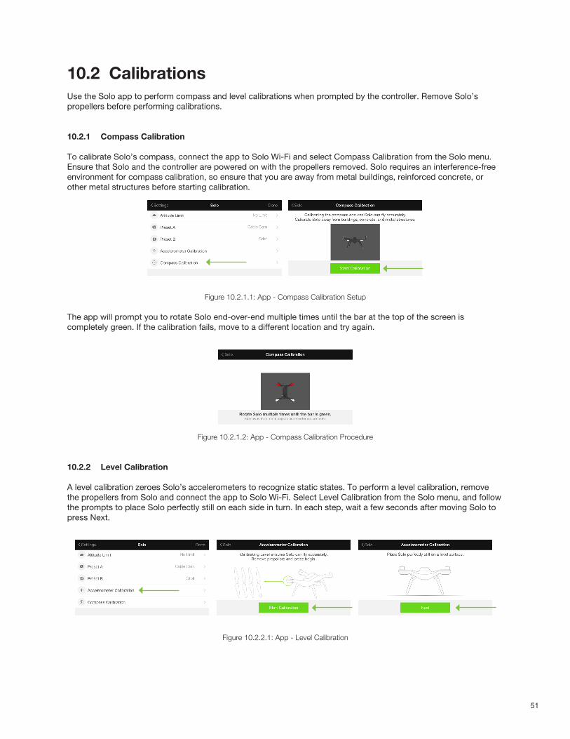
51
10.2 CalibrationsUse the Solo app to perform compass and level calibrations when prompted by the controller. Remove Solo’s propellers before performing calibrations.
10.2.1 Compass Calibration
To calibrate Solo’s compass, connect the app to Solo Wi-Fi and select Compass Calibration from the Solo menu. Ensure that Solo and the controller are powered on with the propellers removed. Solo requires an interference-free environment for compass calibration, so ensure that you are away from metal buildings, reinforced concrete, or other metal structures before starting calibration.
Figure 10.2.1.1: App - Compass Calibration Setup
The app will prompt you to rotate Solo end-over-end multiple times until the bar at the top of the screen is completely green. If the calibration fails, move to a different location and try again.
Figure 10.2.1.2: App - Compass Calibration Procedure
10.2.2 Level Calibration
A level calibration zeroes Solo’s accelerometers to recognize static states. To perform a level calibration, remove the propellers from Solo and connect the app to Solo Wi-Fi. Select Level Calibration from the Solo menu, and follow the prompts to place Solo perfectly still on each side in turn. In each step, wait a few seconds after moving Solo to press Next.
Figure 10.2.2.1: App - Level Calibration

52
10.3 Pairing the Controller
1 Turn off the Solo and the controller that you want to pair, along with any other Solos and controllers nearby.
2 Power on the Solo and controller that you want to pair.
3 Wait 30 seconds for Solo and the controller to fully boot up.
4 Identify the Pair button underneath Solo. It’s a small button inside the hole labeled Pair. You’ll need to use a paper clip, a small screwdriver, or another similar tool to push it.
Figure 10.3.1: Pair Button
5 Press the Pair button underneath Solo and hold for one second.
6 When the controller detects Solo, it prompts you to accept the pairing request as seen in the screen below. (If the controller does not detect Solo after thirty seconds, try pressing the Pair button underneath Solo again and repeat as needed.)
Figure 10.3.2: Detected Solo
7 Press A, then B and hold both buttons down. Once the controller vibrates, release the buttons. Within 20 seconds, the Controller displays “Solo Paired.”
Figure 10.3.3: Solo Paired

53
10.4 LegsSolo uses three unique types of legs: two legs with an antenna module (#1 and #2), a leg with no electronic components (leg #3), and a leg with a compass module (leg #4). You can purchase replacements for all types of leg from store.3dr.com or an authorized retailer.
Figure 10.4.1: Leg Types
10.4.1 Leg #3
To replace a standard leg, use a #2 Phillips screwdriver to remove the two screws, detach the old leg, and attach the new leg using the provided screws.
Figure 10.4.1.1: Standard Leg Replacement Process
10.4.2 Legs #1 and #2 with Antennas
To replace a leg with an antenna module where the existing antenna is physically intact, you’ll need to remove the antenna from the old leg before replacing it.
To detach the antenna, remove the plastic sheet from the leg (1) and detach the antenna from the Velcro by carefully pulling the cable (2). Follow the standard leg replacement procedure to detach the old leg (3).
1
Compass
Antenna
Antenna
Standard
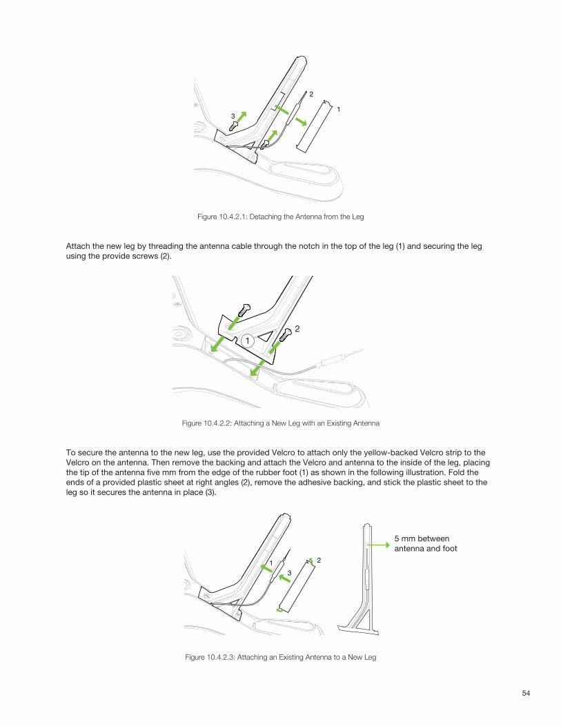
54
Figure 10.4.2.1: Detaching the Antenna from the Leg
Attach the new leg by threading the antenna cable through the notch in the top of the leg (1) and securing the leg using the provide screws (2).
Figure 10.4.2.2: Attaching a New Leg with an Existing Antenna
To secure the antenna to the new leg, use the provided Velcro to attach only the yellow-backed Velcro strip to the Velcro on the antenna. Then remove the backing and attach the Velcro and antenna to the inside of the leg, placing the tip of the antenna five mm from the edge of the rubber foot (1) as shown in the following illustration. Fold the ends of a provided plastic sheet at right angles (2), remove the adhesive backing, and stick the plastic sheet to the leg so it secures the antenna in place (3).
Figure 10.4.2.3: Attaching an Existing Antenna to a New Leg
1
2
3
21
3
21
5 mm between antenna and foot

55
10.4.3 Leg #4 with Compass
Solo’s right-rear leg (#4) contains the compass module. Start by detaching the leg from the arm as you would a standard leg, but the leg will not be removable until you disconnect the compass from Solo. To access the compass connector, you’ll need to remove the battery tray from Solo. For battery tray removal instructions, see Section 10.5.
With the battery tray removed, locate the compass connector in the corner of the board closest to the leg being replaced. Disconnect the compass connector from the board by holding down the tab on the far side of the connector and lifting up the connector. Because the space between the arm and the connector is limited, it might help to use a screwdriver to press the tab.
Figure 10.4.3.1: Compass Connector on Mainboard
With the compass disconnected, remove the old leg and cable from Solo. Place the new leg into position and thread the new compass cable through the arm where it can connect to the board. Connect the compass connector in the same place as the old compass.
Figure 10.4.3.2: Insert New Leg with Compass
Secure the new leg in place and replace the battery tray.
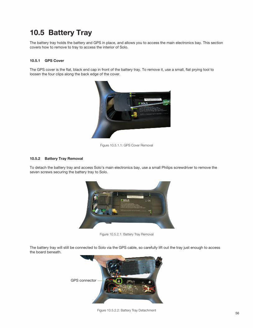
56
10.5 Battery TrayThe battery tray holds the battery and GPS in place, and allows you to access the main electronics bay. This section covers how to remove to tray to access the interior of Solo.
10.5.1 GPS Cover
The GPS cover is the flat, black end cap in front of the battery tray. To remove it, use a small, flat prying tool to loosen the four clips along the back edge of the cover.
Figure 10.5.1.1: GPS Cover Removal
10.5.2 Battery Tray Removal
To detach the battery tray and access Solo’s main electronics bay, use a small Philips screwdriver to remove the seven screws securing the battery tray to Solo.
Figure 10.5.2.1: Battery Tray Removal
The battery tray will still be connected to Solo via the GPS cable, so carefully lift out the tray just enough to access the board beneath.
Figure 10.5.2.2: Battery Tray Detachment
GPS connector
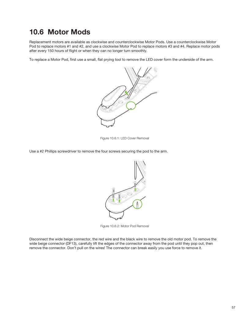
57
10.6 Motor ModsReplacement motors are available as clockwise and counterclockwise Motor Pods. Use a counterclockwise Motor Pod to replace motors #1 and #2, and use a clockwise Motor Pod to replace motors #3 and #4. Replace motor pods after every 150 hours of flight or when they can no longer turn smoothly.
To replace a Motor Pod, first use a small, flat prying tool to remove the LED cover form the underside of the arm.
Figure 10.6.1: LED Cover Removal
Use a #2 Phillips screwdriver to remove the four screws securing the pod to the arm.
Figure 10.6.2: Motor Pod Removal
Disconnect the wide beige connector, the red wire and the black wire to remove the old motor pod. To remove the wide beige connector (DF13), carefully lift the edges of the connector away from the pod until they pop out, then remove the connector. Don’t pull on the wires! The connector can break easily you use force to remove it.
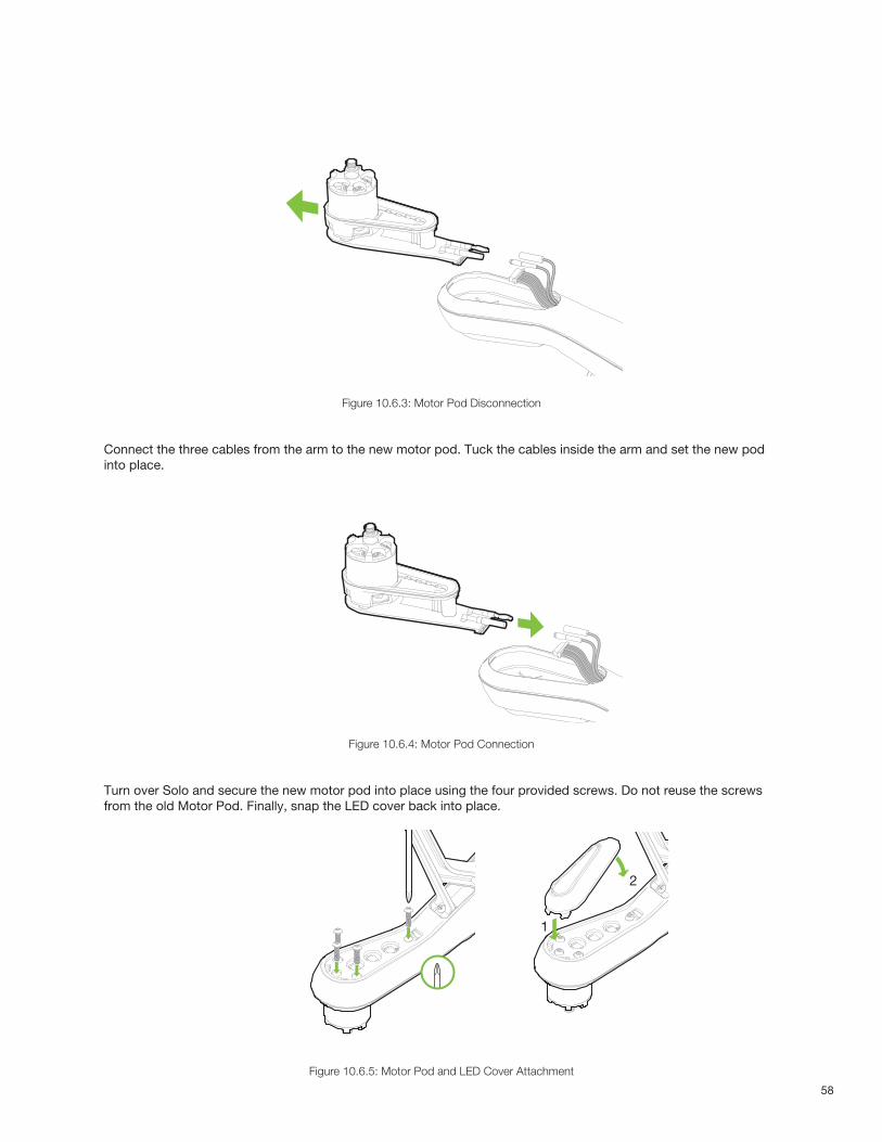
58
Figure 10.6.3: Motor Pod Disconnection
Connect the three cables from the arm to the new motor pod. Tuck the cables inside the arm and set the new pod into place.
Figure 10.6.4: Motor Pod Connection
Turn over Solo and secure the new motor pod into place using the four provided screws. Do not reuse the screws from the old Motor Pod. Finally, snap the LED cover back into place.
Figure 10.6.5: Motor Pod and LED Cover Attachment
1
2
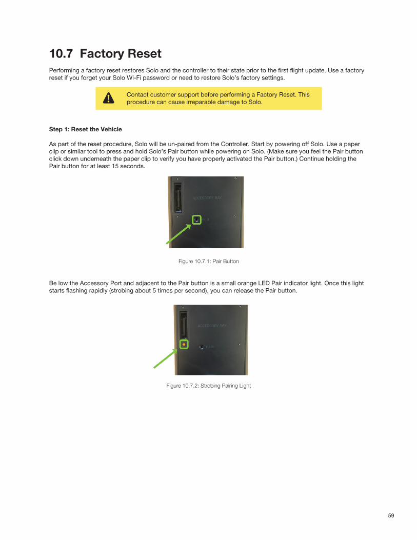
59
10.7 Factory ResetPerforming a factory reset restores Solo and the controller to their state prior to the first flight update. Use a factory reset if you forget your Solo Wi-Fi password or need to restore Solo’s factory settings.
Step 1: Reset the Vehicle
As part of the reset procedure, Solo will be un-paired from the Controller. Start by powering off Solo. Use a paperclip or similar tool to press and hold Solo’s Pair button while powering on Solo. (Make sure you feel the Pair buttonclick down underneath the paper clip to verify you have properly activated the Pair button.) Continue holding thePair button for at least 15 seconds.
Figure 10.7.1: Pair Button
Be low the Accessory Port and adjacent to the Pair button is a small orange LED Pair indicator light. Once this lightstarts flashing rapidly (strobing about 5 times per second), you can release the Pair button.
Figure 10.7.2: Strobing Pairing Light
Contact customer support before performing a Factory Reset. This procedure can cause irreparable damage to Solo.
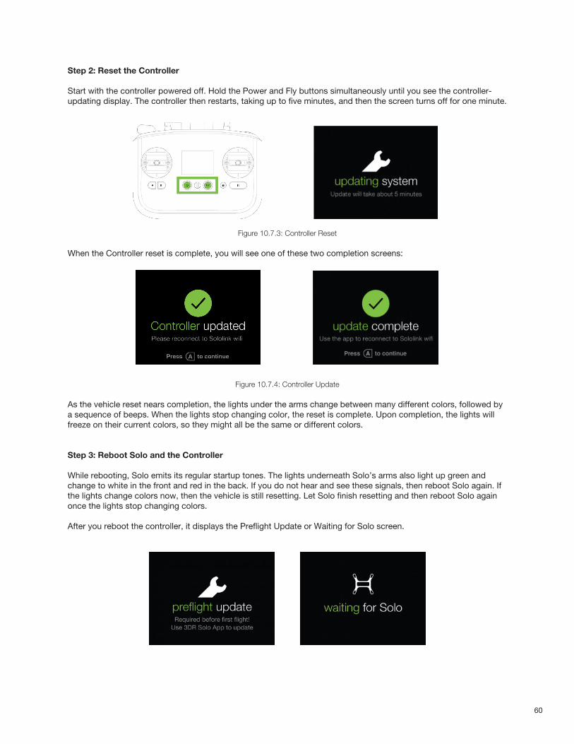
60
Step 2: Reset the Controller
Start with the controller powered off. Hold the Power and Fly buttons simultaneously until you see the controller-updating display. The controller then restarts, taking up to five minutes, and then the screen turns off for one minute.
Figure 10.7.3: Controller Reset
When the Controller reset is complete, you will see one of these two completion screens:
Figure 10.7.4: Controller Update
As the vehicle reset nears completion, the lights under the arms change between many different colors, followed by a sequence of beeps. When the lights stop changing color, the reset is complete. Upon completion, the lights will freeze on their current colors, so they might all be the same or different colors.
Step 3: Reboot Solo and the Controller
While rebooting, Solo emits its regular startup tones. The lights underneath Solo’s arms also light up green and change to white in the front and red in the back. If you do not hear and see these signals, then reboot Solo again. If the lights change colors now, then the vehicle is still resetting. Let Solo finish resetting and then reboot Solo again once the lights stop changing colors.
After you reboot the controller, it displays the Preflight Update or Waiting for Solo screen.
61
Step 4: Pair Solo and the Controller
For instructions how to pair Solo and the Controller, see section 10.3.
Step 5: Update your system
For instructions how to update your system, see section 2.6.4. The Factory Reset procedure is now complete.
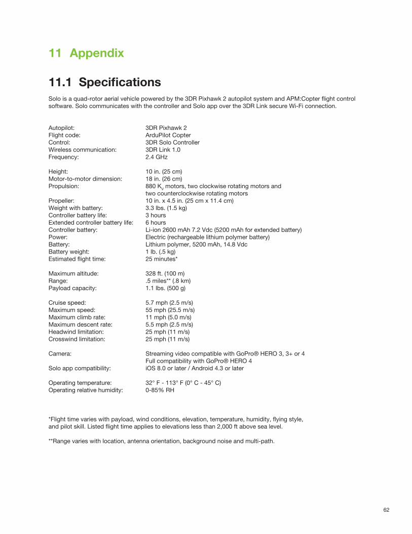
62
11 Appendix
11.1 SpecificationsSolo is a quad-rotor aerial vehicle powered by the 3DR Pixhawk 2 autopilot system and APM:Copter flight control software. Solo communicates with the controller and Solo app over the 3DR Link secure Wi-Fi connection.
Autopilot: 3DR Pixhawk 2Flight code: ArduPilot CopterControl: 3DR Solo ControllerWireless communication: 3DR Link 1.0Frequency: 2.4 GHz
Height: 10 in. (25 cm)Motor-to-motor dimension: 18 in. (26 cm)Propulsion: 880 KV motors, two clockwise rotating motors and two counterclockwise rotating motorsPropeller: 10 in. x 4.5 in. (25 cm x 11.4 cm)Weight with battery: 3.3 lbs. (1.5 kg)Controller battery life: 3 hoursExtended controller battery life: 6 hoursController battery: Li-ion 2600 mAh 7.2 Vdc (5200 mAh for extended battery)Power: Electric (rechargeable lithium polymer battery)Battery: Lithium polymer, 5200 mAh, 14.8 VdcBattery weight: 1 lb. (.5 kg)Estimated flight time: 25 minutes*
Maximum altitude: 328 ft. (100 m)Range: .5 miles** (.8 km)Payload capacity: 1.1 lbs. (500 g)
Cruise speed: 5.7 mph (2.5 m/s)Maximum speed: 55 mph (25.5 m/s)Maximum climb rate: 11 mph (5.0 m/s)Maximum descent rate: 5.5 mph (2.5 m/s)Headwind limitation: 25 mph (11 m/s)Crosswind limitation: 25 mph (11 m/s)
Camera: Streaming video compatible with GoPro® HERO 3, 3+ or 4 Full compatibility with GoPro® HERO 4Solo app compatibility: iOS 8.0 or later / Android 4.3 or later
Operating temperature: 32° F - 113° F (0° C - 45° C)Operating relative humidity: 0-85% RH
*Flight time varies with payload, wind conditions, elevation, temperature, humidity, flying style, and pilot skill. Listed flight time applies to elevations less than 2,000 ft above sea level.
**Range varies with location, antenna orientation, background noise and multi-path.
63
11.2 Warranty
3D Robotics warrants to the original retail purchaser of Solo (the “Product”) that at the time of purchase that this product is free from material defect in materials and workmanship. Should this Product fail during normal consumer usage and conditions due to defective material or workmanship within one year from the date of purchase, or such longer period as is required by applicable law (“Warranty Period”), such defect(s) will be repaired or replaced at 3D Robotics’ option, without charge for parts or labor directly related to the defect(s). The complete terms of the limited warranty applicable to Solo can be found at 3dr.com/terms. This Warranty extends only to consumers who purchase the product from a 3D Robotics authorized reseller and is not transferable or assignable. This Warranty does not apply to: (1) Product subjected to abnormal use or conditions, accident (including without limitation, collision, crash or fire), alteration, or improper repair; (2) damage from exposure to moisture or extreme environmental conditions; (3) damage from use with any accessory, software or other product not expressly authorized by 3D Robotics; (4) damage from external causes such as dirt, sand, battery leakage, blown fuse, or improper usage of any electrical source; (5) commercial use; or (6) use in violation of law or ordinances in effect in the jurisdiction in which the Product is used.
3D Robotics assumes no liability for any accident, injury, death, loss, or other claim related to or resulting from the use of this product. 3D Robotics makes no other warranties for Solo, and makes no warranties whatsoever for service, software, maintenance or support for non-3D Robotics branded products. Such products, service, software, maintenance or support is provided by 3D Robotics “As Is” and any third-party warranties, products, software, services, maintenance or support are provided by the original manufacturer or supplier, not by 3D Robotics.
Software is subject to the separate software license agreement accompanying or made available to you in connection with the software. A portion of the software contains or consists of open-source software, which you may use under the terms and conditions of the specific license under which the open-source software is distributed. You agree that you will be bound by any and all such license agreements, and that your usage of this product indicates your acceptance of those agreements. Title to software remains with the applicable licensor(s). In no event will 3D Robotics be liable to you for damages, including any general, special, incidental or consequential damages arising out of the use or inability to use the software.
THE EXTENT OF 3D ROBOTICS’ LIABILITY UNDER THIS WARRANTY IS LIMITED TO THE REPAIR OR REPLACEMENT PROVIDED ABOVE AND, IN NO EVENT, SHALL ITS LIABILITY EXCEED THE PURCHASE PRICE PAID BY PURCHASER FOR THE PRODUCT.
11.3 Regulatory Compliance
11.3.1 U.S. - FCC (Federal Communication Commission)
3DR Solo FCC: 2ADYD-S111A3DR Solo Controller FCC: 2ADYD-AT11A
This device complies with Part 15 of the FCC rules. Operation is subject to the following two conditions: (1) This device may not cause harmful interference, and (2) this device must accept any interference received, including interference that may cause undesired operation.
Changes or modifications not expressly approved by 3D Robotics could void the user’s authority to operate the equipment.
Radiation Exposure Statement:The Solo system has been tested to ensure compliance with FCC-mandated limits for general population radio frequency (RF) exposure for an uncontrolled environment. These limits ensure that no harmful effects will result from operating Solo according to the standard operating procedures described in this manual.
64
The body’s Specific Absorption Rate (SAR) for the Solo controller is 1.33 watts per kilogram (W/kg) in compliance with the FCC limit of 1.6 W/kg. To reduce exposure to RF energy, hold Solo at least 20 cm away from your body at all times during operation. Do not operate the Solo controller co-located or in conjunction with any other antenna or transmitter. This device complies with Part 15 of the FCC Rules. Operation is subject to the condition that this device does not cause harmful interference.
11.3.2 Canada - Industry Canada
3DR Solo IC: 12768A-S114AModel number: S110A
3DR Solo Controller IC: 12768A-AT14AModel number: AT10A
This device complies with Industry Canada license-exempt RSS standard(s). Operation is subject to the following two conditions: (1) this device may not cause interference, and (2) this device must accept any interference, including interference that may cause undesired operation of the device.
Le présent appareil est conforme aux CNR d’Industrie Canada applicables aux appareils radio exempts de licence. L’exploitation est autorisée aux deux conditions suivantes : (1) l’appareil ne doit pas produire de brouillage, et (2) l’utilisateur de l’appareil doit accepter tout brouillage radioélectrique subi, même si le brouillage est susceptible d’en compromettre le fonctionnement.
IC Radiation Exposure Statement:The Solo system has been tested to ensure compliance with IC-mandated limits for general population radio frequency (RF) exposure for an uncontrolled environment. These limits ensure that no harmful effects will result from operating Solo according to the standard operating procedures described in this manual. To reduce exposure to RF energy, hold Solo at least 20 cm away from your body at all times during operation. Do not operate the Solo controller co-located or in conjunction with any other antenna or transmitter. Changes or modifications not expressly approved by 3D Robotics could void the user’s authority to operate the equipment.