Embed Size (px)
Citation preview
Experience In Motion
USER INSTRUCTIONS
InstallationOperation
Maintenance
Limitorque ® UEXElectronic Controls Module
FCD LMENIM1205-04-A4 – 11/15
Limitorque UEX FCD LMENIM1205-04-A4 – 11/15
2
Contents1. Introduction 4
1.1 Purpose 41.2 User Safety 41.3 Product Description 5
2. Safety 62.1 Safety Precautions 62.2 Safety Practices 7
3. Limit Switch and Torque Switch Setting Procedures 83.1 Initial Actuator Preparation 83.2 Torque Switch 8 3.2.1 Setting Torque Switch 8
3.2.2 Balancing Torque Switch 93.3 Geared Limit Switch 10
3.3.1 Setting Limit Switch 103.3.2 Setting Procedure (Refer to Figure 3.2) 113.3.3 Combination of Contacts (Refer to Figure 3.2) 12
4. Removal of UEC-3 Electronic Controller 135. UEX Electronic Controller Installation 186. Standard Control Features 22
6.1 Basic Specifications 226.2 Local Control 236.3 Remote Control Modes of Operation 236.4 Emergency Shutdown (ESD) 246.5 Remote External Interlocks/Inhibits 256.6 Absolute Position Encoder 25
7. Protection Features 267.1 Autophase Protection and Correction 267.2 Jammed Valve Protection 267.3 Instantaneous Reversal Protection 26 7.4 Motor Thermal Protection 26
8. Optional Control Features 278.1 Modutronic 278.2 Analog Position Transmitter (APT) 288.3 Two-Speed Timer 28 8.4 Control Station (CSE) 28
9. Network Communications 299.1 Modbus™ 299.2 Master Station III 309.3 Foundation Fieldbus Communication 309.4 PROFIBUS DP V1 Communication 319.5 PROFIBUS PA Communication 319.6 DeviceNet 32
10. Monitoring and Diagnostic Features 3310.1 Local Features 3310.2 Diagnostics 34
11. Remote Indication Features 3611.1 Actuator Status Contacts (S1a, S1b, S2a, S2b) 3611.2 Monitor Relay (RM) 3711.3 Exact End Position Indication 37
12. Auxiliary Power Supply 38
3
Limitorque UEX FCD LMENIM1205-04-A4 – 11/15
flowserve.com
13. Isolated Commons 3914. Actuator Configuration 40
14.1 Local Configuration 4014.2 Default Configuration 4014.3 Setup Menus 42
15. UEX Wiring Diagrams 6116. Network Protocol Connections 67
16.1 Network Wiring – Modbus 6716.2 Network Wiring – Foundation Fieldbus H1 6916.3 Network Wiring – Profibus DP and PA 7116.4 Network Wiring – DeviceNet 72
17. How to Order Parts 7418. Regulatory Information 75
Figures and TablesFigure 1.1 – UEX Local Control Panel 5Figure 3.1 – Microswitch-Style Torque Switch and 600 Volt Torque Switch 9Figure 3.2 – Limit Switch 11Figure 3.3 – Setting the Open and Closed Contacts 12Figure 4.1 – Removal of the UEC-3 Electronic Controller 14Figure 4.2 – UEC-3, MPC, DDC Assembly 17Figure 5.1 – Encoder / MDPI / Transformer Installation 19Figure 5.2 – Power / Interface Board Assembly 19Figure 5.3 – Main Board Set Installation 20Figure 5.4 – CSE Jumper Assembly 20Figure 5.5 – CSE Control Station 20Figure 5.6 – Controls Compartment Assembly 21Figure 6.1 – UEX Local Control Panel 22Figure 6.2 – Absolute Position Encoder 25Figure 10.1 – Normal and Diagnostic Displays 35Figure 14.1 – Configuring the UEX Controller 41Figure 15.1 – Standard Wiring Diagram for UEX Controllers 62Figure 15.2 – DDC Wiring Diagram for UEX Controllers 63Figure 15.3 – MOD APT Wiring Diagram for UEX Controllers 64Figure 15.4 – Optional Features Wiring Diagrams 65Figure 15.5 – Modbus, Foundation Fieldbus, Profibus DP V1, and Profibus PA, 66
and DeviceNet Network Wiring DiagramsFigure 16.1 – Typical Modbus Network Wiring Diagrams – Single Loop 68Figure 16.2 – Typical Foundation Fieldbus System with a DCS Host (Daisy Chain Shown) 70Figure 16.3 – Typical Profibus System with a DCS Host (Daisy Chain Shown) 72Table 1.1 – Standard Application Voltages with +/- 10% Nominal Range 5Table 2.1 – Required Rating for External Wiring 7Table 3.1 – Maximum Number of Drive Sleeve Turns for Standard Four-Gear 10
and Optional Five-Gear Limit Switches Table 3.2 – Limit Switch Parts 11Table 5.1 – UEX Parts List 21Table 14.1 – Default Configuration Guidelines 41Table 16.1 – Specifications for the Profibus Cable 71Table 16.2 – Maximum Segment Length 71Table 16.3 – Belden Cable Specifications 73Table 16.4 – Total Cable Length Between Repeaters or Nodes 73
Limitorque UEX FCD LMENIM1205-04-A4 – 11/15
4
1 Introduction
1.1 PurposeThis Installation and Maintenance Manual explains how to install, setup, and maintain the UEX controller for the L120-10, L120-20, L120-40, and L120-85 actuators. Information on installation, operation, control features, and maintenance is provided.
Contact Flowserve Limitorque if assistance is needed or preferred for installation, upgrading, or training in the operation of the UEX.
1.2 User Safety Safety notices in this manual detail precautions the user must take to reduce the risk of personal injury and damage to the equipment. The user must read and be familiar with these instructions before attempting installation, operation, or maintenance. Work should be performed by a qualified tradesman who is familiar with the operation and maintenance of electric actuators. Failure to observe these precautions could result in serious bodily injury or death, damage to the equipment, voiding of the warranty, or operational difficulty.
Safety notices are presented in this manual in three forms:
c WARNING: Refers to personal safety. Alerts the user to potential danger. Failure to follow warning notices could result in personal injury or death.
a CAUTION: Directs the user’s attention to general precautions that, if not followed, could result in personal injury and/or equipment damage.
NOTE: Highlights information critical to the user’s understanding of the actuator’s installation and operation.
5
Limitorque UEX FCD LMENIM1205-04-A4 – 11/15
flowserve.com
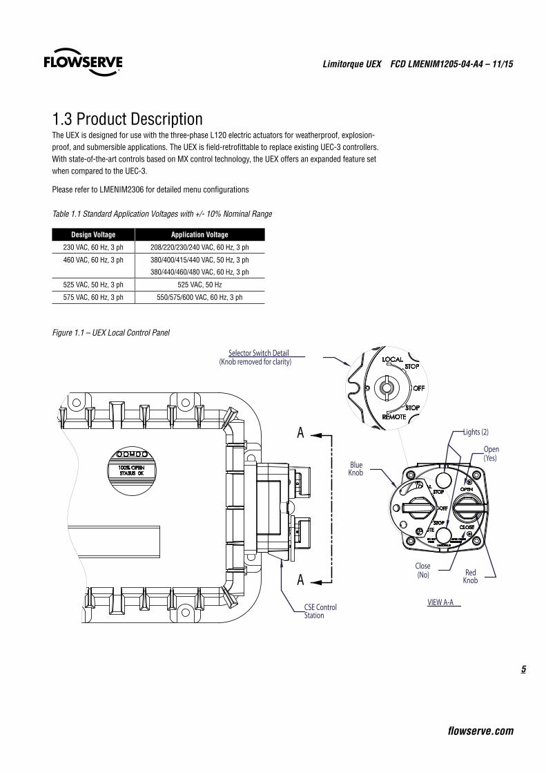
1.3 Product DescriptionThe UEX is designed for use with the three-phase L120 electric actuators for weatherproof, explosion-proof, and submersible applications. The UEX is field-retrofittable to replace existing UEC-3 controllers. With state-of-the-art controls based on MX control technology, the UEX offers an expanded feature set when compared to the UEC-3.
Please refer to LMENIM2306 for detailed menu configurations
Table 1.1 Standard Application Voltages with +/- 10% Nominal Range
Design Voltage Application Voltage
230 VAC, 60 Hz, 3 ph 208/220/230/240 VAC, 60 Hz, 3 ph
460 VAC, 60 Hz, 3 ph 380/400/415/440 VAC, 50 Hz, 3 ph
380/440/460/480 VAC, 60 Hz, 3 ph
525 VAC, 50 Hz, 3 ph 525 VAC, 50 Hz
575 VAC, 60 Hz, 3 ph 550/575/600 VAC, 60 Hz, 3 ph
Figure 1.1 – UEX Local Control Panel
VIEW A-A
BlueKnob
RedKnob
Open(Yes)
Close(No)
Lights (2)
CSE ControlStation
Selector Switch Detail(Knob removed for clarity)
A
A
Limitorque UEX FCD LMENIM1205-04-A4 – 11/15
6
2.1 Safety Precautions c WARNING: Read this Installation and Maintenance Manual carefully and completely before
attempting to install, operate, or troubleshoot the Limitorque L120 actuator.
c WARNING: Be aware of electrical hazards. Turn off incoming power before working on the actuator and before opening the switch compartment.
c WARNING: Potential HIGH-PRESSURE vessel – Be aware of high-pressure hazards associated with the attached valve or other actuated device when installing or performing maintenance on your L120 actuator. Do not remove the actuator mounting bolts when the actuator is mounted on a rising stem valve unless the valve is in the FULLY OPEN position and there is NO pressure in the line.
c WARNING: Do not manually operate the actuator with devices other than installed Handwheel and Declutch Lever. Using force beyond the ratings of the unit and/or using additive force devices such as cheater bars, wheel wrenches, pipe wrenches, or other devices on the actuator Handwheel or Declutch Lever may cause serious personal injury and/or damage to the actuator or valve.
c WARNING: For maintenance and/or disassembly of the actuator while installed on the valve, ensure that the actuator is not under thrust or torque load. If the valve must be left in service, the valve stem must be locked in such a way as to prevent any movement of the valve stem.
c WARNING: For maintenance and/or disassembly of the actuator while installed on the valve, ensure that the actuator is not under thrust or torque load. If the valve must be left in service, the valve stem must be locked in such a way as to prevent any movement of the valve stem.
c WARNING: Do not attempt to remove the spring cartridge cap, housing cover, or stem nut locknut from the actuator while the valve or actuated device is under load.
c WARNING: Do not exceed any design limitations or make modifications to this equipment without first consulting Limitorque.
c WARNING: Actuators equipped with electrical devices (motors, controls) requiring field wiring must be wired and checked for proper operation by a qualified tradesman.
2 Safety
7
Limitorque UEX FCD LMENIM1205-04-A4 – 11/15
flowserve.com
c WARNING: Use of the product must be suspended any time it fails to operate properly.
c WARNING: Do not work on the actuator while it is mounted on a torque-seated valve.
a CAUTION: Do not use oversized motor overload heaters. Instead, look for the cause of the overload.
a CAUTION: Do not operate the valve under motor operation without first setting or checking the limit switch setting and motor direction.
a CAUTION: Do not force the declutch lever into the motor operation position. The lever returns to this position automatically when the motor is energized.
a CAUTION: Do not depress the declutch lever during motor operation to stop valve travel.
a CAUTION: Do not use replacement parts that are not genuine Flowserve Limitorque parts, as serious personal injury and/or damage to the actuator and valve may result.
a CAUTION: Do not lift actuator/gearbox or actuator/valve combinations with only the eye bolts in the L120 actuator. These eye bolts are designed for lifting the L120 actuator only.
a CAUTION: Do not lift the actuator by the handwheel
2.2 Safety PracticesThe following checks should be performed to maintain safe operation of the L120 actuator.
• Mount motors on a horizontal plane, if possible.
• Keep the controls compartment clean and dry.
• Keep the valve stem clean and lubricated.
• Set up a periodic operating schedule for infrequently used valves.
• Verify the stem nut is secured tightly by the locknut and that the top thread of the locknut is crimped or staked in two places.
• Use a protective stem cover for rising stem valves. Check valve stem travel and clearance before mounting covers on rising stem valves.
• Verify all actuator wiring is in accordance with the applicable wiring diagram, national and local codes, and Table 2.1.
Table 2.1 – Required Rating for External Wiring
Up to: Use wire rated at least:
40°C 60°C
60°C 75°C
Limitorque UEX FCD LMENIM1205-04-A4 – 11/15
8
3.1 Initial Actuator PreparationReplace all molded plastic conduit and top protectors (installed for shipping purposes only) with pipe plugs when installation wiring is complete.
3.2 Torque SwitchThe torque switch is designed to protect the actuator in open and close directions.
a CAUTION: Disconnect all incoming power before opening limit switch compartment or working on the torque switch.
• Do not use abrasive cloth to clean the contacts on the torque switch.
• Do not torque seat 90° operation valves nor run them against the stops. This may cause damage to the valve.
NOTE: If the actuator operation has been interrupted by the tripping of the torque switch, release torque buildup by operating the actuator manually in the opposite direction until the load is released and the dial has returned to the center position.
3.2.1 Setting Torque SwitchThe torque switch was set at the factory according to customer-supplied information regarding necessary torque or thrust output that was provided at the time of the order. The procedure below is provided in the event that the setting needs to be adjusted:
a CAUTION: A torque switch limiter plate is provided on most actuators. Do not remove this plate. Do not exceed the setting indicated by this plate without first contacting Flowserve Limitorque service.
• Removal or modification of the torque switch limiter plate will void the actuator warranty.
3 Limit Switch & Torque Switch Setting Procedures
9
Limitorque UEX FCD LMENIM1205-04-A4 – 11/15
flowserve.com
a CAUTION: Installing or adjusting the torque switch with the actuator under load will result in a loss of torque protection.
NOTE: Item letters correspond to Figure 3.1.
1. Place the L120 actuator in manual mode by pulling the declutch lever in the direction shown on the lever.
2. Release the load on the wormshaft spring pack by rotating the handwheel until the valve disk position approximates 50% open.
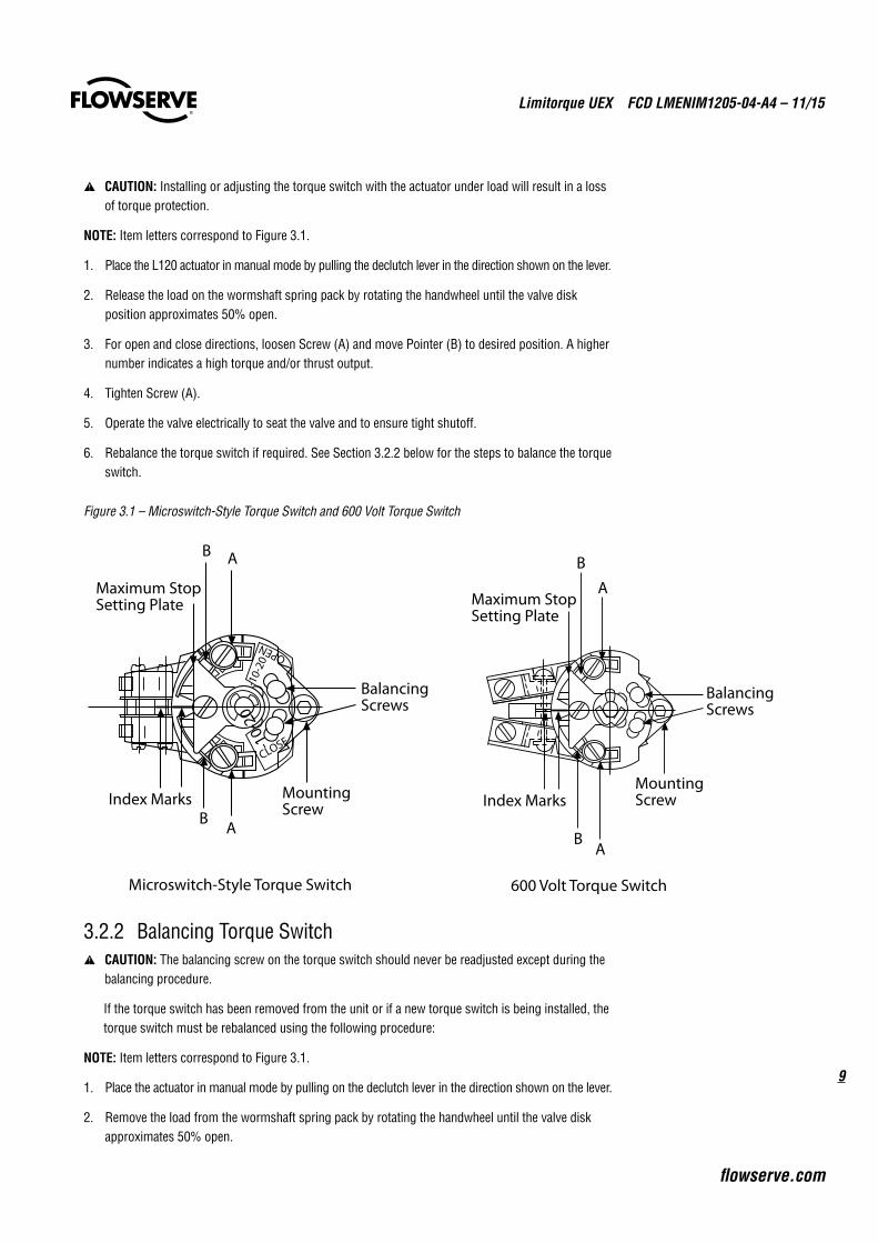
3. For open and close directions, loosen Screw (A) and move Pointer (B) to desired position. A higher number indicates a high torque and/or thrust output.
4. Tighten Screw (A).
5. Operate the valve electrically to seat the valve and to ensure tight shutoff.
6. Rebalance the torque switch if required. See Section 3.2.2 below for the steps to balance the torque switch.
Figure 3.1 – Microswitch-Style Torque Switch and 600 Volt Torque Switch
3.2.2 Balancing Torque Switch a CAUTION: The balancing screw on the torque switch should never be readjusted except during the
balancing procedure.
If the torque switch has been removed from the unit or if a new torque switch is being installed, the torque switch must be rebalanced using the following procedure:
NOTE: Item letters correspond to Figure 3.1.
1. Place the actuator in manual mode by pulling on the declutch lever in the direction shown on the lever.
2. Remove the load from the wormshaft spring pack by rotating the handwheel until the valve disk approximates 50% open.
MountingScrewIndex Marks
Maximum StopSetting Plate
A
B
BalancingScrews
600 Volt Torque Switch
AB
B A
B A
Microswitch-Style Torque Switch
MountingScrew
Index Marks
Maximum StopSetting Plate
BalancingScrews
-10-
20
CLOSE
OPEN
-10-
20
Limitorque UEX FCD LMENIM1205-04-A4 – 11/15
10
3. Note the open and close torque switch settings prior to reinstalling the torque switch.
4. Loosen Screws (A) and position both Pointers (B) at the #1 setting, tighten Screw (A). In this position the index marks should be aligned.
5. Loosen balancing screws and install the torque switch. The base of the torque switch should be flush against the compartment and the hole for the mounting screw should be aligned.
6. Install the mounting screw.
7. Tighten the balancing screws.
a CAUTION: The balancing screws should not be touched except during the balancing procedure.
The switch is now balanced and ready for the pointers to be returned to their original settings.
3.3 Geared Limit Switch a CAUTION: The geared limit switch is not preset at the factory and must be adjusted after the
actuator has been mounted on associated equipment.
• Disconnect all incoming power to the actuator prior to opening the limit switch compartment and adjusting the switch.
• Consult the relevant wiring diagram for limit switch contact development. All L120 units are supplied with 16-contact limit switches - four switches on each of the four rotors. Two rotors are used for end of travel indication. The remaining two rotors may be adjusted for any intermediate point of travel.
• Do not use abrasive cloth to clean the contacts on the limit switch.
• Do not attempt to repair gearing in the limit switch. Replace entire gear frame assembly if necessary.
3.3.1 Setting the Limit SwitchSet the limit switch as follows. All item letters and piece numbers refer to Figure 3.2.
NOTE: The chart below provides the maximum number of drive sleeve turns for each actuator size. The Intermediate Shaft (B), shown in Figure 3.2, may require a considerable number of turns before rotor trip occurs.
Table 3.1 – Maximum Number of Drive Sleeve Turns for Standard Four-Gear and Optional Five-Gear Limit Switches
Actuator Size Four-Gear Five-Gear
L120-10 630 6300
L120-20 740 7400
L120-40 640 6400
c WARNING: Potential Explosion Hazard. Do not use an electric drill for setting the limit switch in an explosive environment.
a CAUTION: When setting the limit switch rotor segments (cams) using a variable speed electric drill, do not run drill at speeds higher than 200 RPM. Operating the drill at high speeds can damage the gearing within the limit switch.
11
Limitorque UEX FCD LMENIM1205-04-A4 – 11/15
flowserve.com
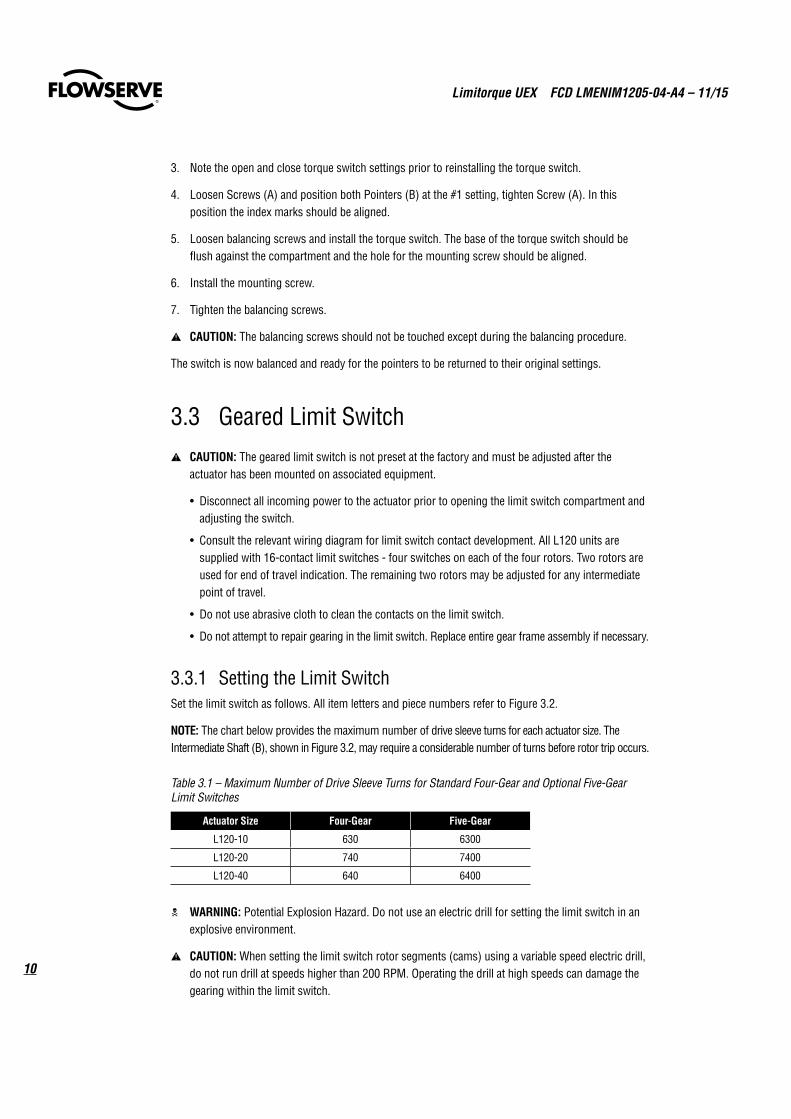
Figure 3.2 – Limit Switch
Table 3.2 – Limit Switch Parts
Piece Quantity Description1 1 Gear Frame Assembly2 2 Eight-Switch Contact Block Assy.3 12 Rotor Segment (short)4 4 Rotor Shaft5 4 Machine Screw6 4 Flat Washer7 4 Lock Washer8 8 Hex Nut9 4 Rotor Segments (long)
3.3.2 Limit Switch Setting Procedure (Refer to Figure 3.2)1. Open the Controls Compartment Cover (refer to Figure 5.5).
2. Place the actuator into manual operation by pulling the declutch lever in the direction shown on the lever. Use the handwheel to operate the valve in the “open” direction. While operating the valve, note the direction of the Intermediate Shaft (B) corresponding to the rotor or rotors to be set.
3. When the valve is fully open, rotate the handwheel to operate the valve in the close direction a sufficient number of turns to allow for coast of moving parts, or refer to the valve manufacturer setting requirements.
4. Push in the Setting Rod (A) and turn one-quarter turn. The rod will latch in this depressed position.
12
9
3
4
B
A
6
5
7
8
Limitorque UEX FCD LMENIM1205-04-A4 – 11/15
12
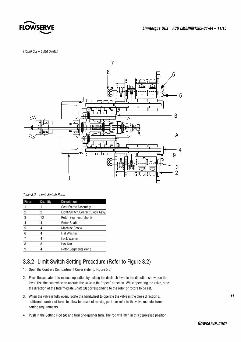
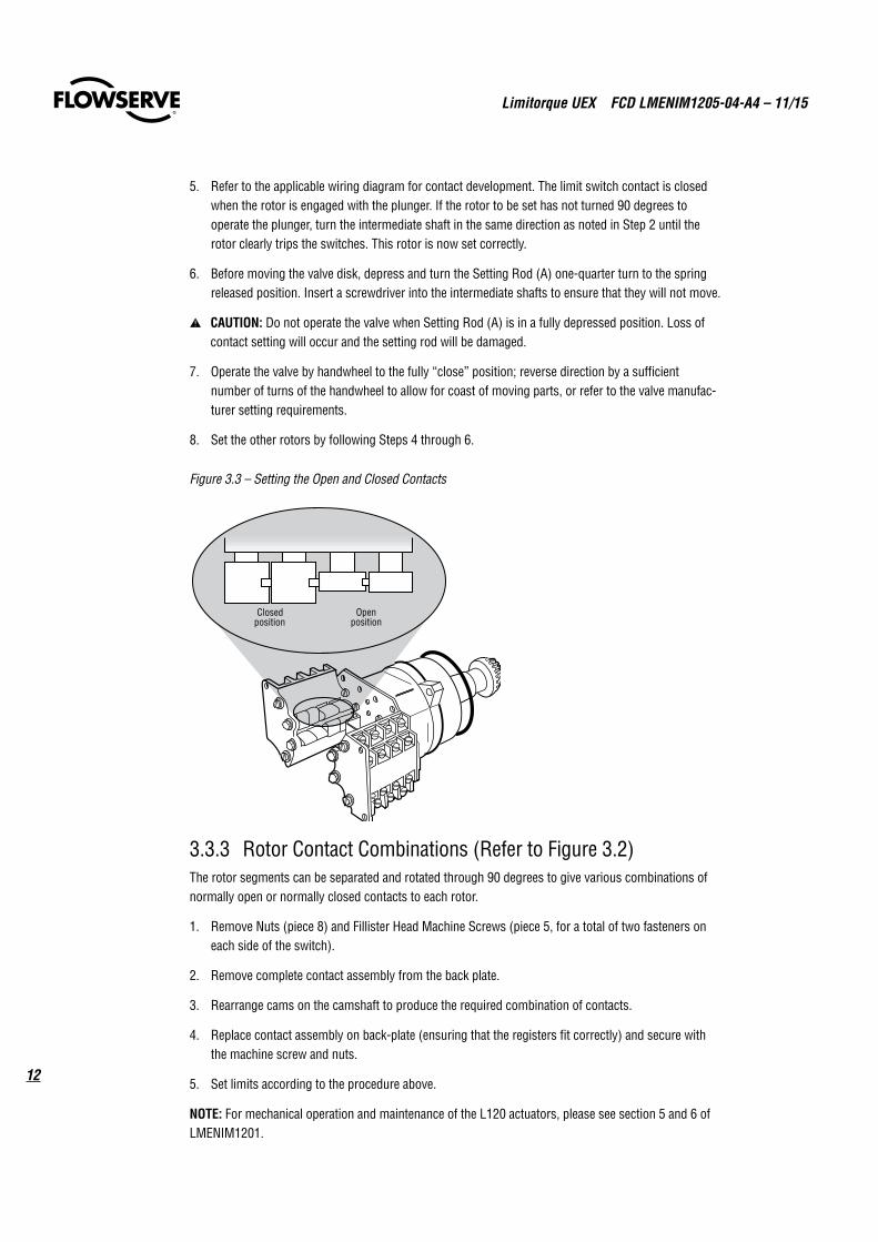
5. Refer to the applicable wiring diagram for contact development. The limit switch contact is closed when the rotor is engaged with the plunger. If the rotor to be set has not turned 90 degrees to operate the plunger, turn the intermediate shaft in the same direction as noted in Step 2 until the rotor clearly trips the switches. This rotor is now set correctly.
6. Before moving the valve disk, depress and turn the Setting Rod (A) one-quarter turn to the spring released position. Insert a screwdriver into the intermediate shafts to ensure that they will not move.
a CAUTION: Do not operate the valve when Setting Rod (A) is in a fully depressed position. Loss of contact setting will occur and the setting rod will be damaged.
7. Operate the valve by handwheel to the fully “close” position; reverse direction by a sufficient number of turns of the handwheel to allow for coast of moving parts, or refer to the valve manufac-turer setting requirements.
8. Set the other rotors by following Steps 4 through 6.
Figure 3.3 – Setting the Open and Closed Contacts
3.3.3 Rotor Contact Combinations (Refer to Figure 3.2)The rotor segments can be separated and rotated through 90 degrees to give various combinations of normally open or normally closed contacts to each rotor.
1. Remove Nuts (piece 8) and Fillister Head Machine Screws (piece 5, for a total of two fasteners on each side of the switch).
2. Remove complete contact assembly from the back plate.
3. Rearrange cams on the camshaft to produce the required combination of contacts.
4. Replace contact assembly on back-plate (ensuring that the registers fit correctly) and secure with the machine screw and nuts.
5. Set limits according to the procedure above.
NOTE: For mechanical operation and maintenance of the L120 actuators, please see section 5 and 6 of LMENIM1201.
Closedposition
Openposition
13
Limitorque UEX FCD LMENIM1205-04-A4 – 11/15
flowserve.com
NOTE: Confirm that the limit switches are set properly prior to disassembly and removal of the UEC-3 and related components. Confirming the settings will allow for installation of the UEX Electronic Controller without requiring a reset of the limit switches.
1. Turn off the power to the actuator.
2. Open the Controls Compartment Cover.
3. Cut and remove all wire ties from wiring that is connected to the UEC-3 assembly (pc# C-201).
4. Disconnect the incoming power from the Interconnect Board.
5. Disconnect the Motor leads and Heater leads from the Interconnect Board.
6. Disconnect the Pushbutton Station ribbon cable from the Interconnect Board.
7. Disconnect the Analog-to-Digital Circuit Board (pc# C-223) ribbon cable from the Interconnect Board.
8. Disconnect the R/I circuit board (pc# C-210) ribbon cable
9. Uninstall the Potentiometer by removing the screws that fasten it to the MDPI assembly.
10. Uninstall the MDPI assembly by removing the screws that fasten it to the Geared Limit Switch assembly.
11. Unplug the optional I/O Circuit Board (pc# C-223) from the SBC Board on the UEC-3 Assembly.
12. Label all customer wiring and disconnect from the Interconnect Boards.
13. Remove the four screws from the UEC-3 Assembly (pc# C-201) and carefully remove the Assembly from the Controls Compartment.
14. Remove the Pushbutton Station with ribbon cable from the L120 gear housing conduit entry.
4 Removal of the UEC-3 Electronic Controller
Limitorque UEX FCD LMENIM1205-04-A4 – 11/15
14
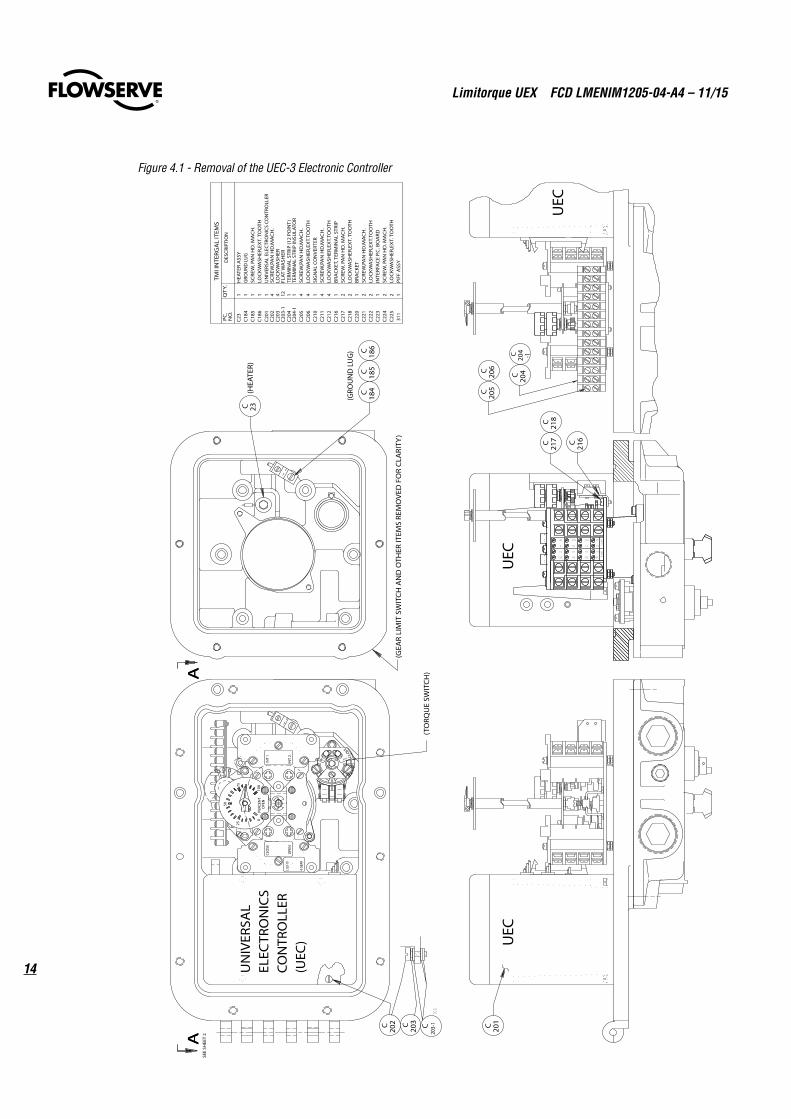
Figure 4.1 - Removal of the UEC-3 Electronic ControllerIN
T.1IN
T.2
12
12C
11
11C
10
10C
9
9C
16
16C
15
15C
14
14C
13
13C
INT.1
INT.2
12
12C
11
11C
10
10C
9
9C
16
16C
15
15C
14
14C
13
13C
UEC
UEC
UEC
AAA
A
UN
IVER
SAL
ELEC
TRO
NIC
SCO
NTR
OLL
ER(U
EC)
CLO
SE
-10-20
PC
.N
O.
QT
Y.D
ESC
RIPT
ION
TMI I
NTE
RGA
L IT
EMS
SCR
EW,P
AN
HD
.MA
CH
.LO
CK
WA
SHER
1C
185
1C
186
SCR
EW, P
AN
HD
. MA
CH
.
1C
201
LOC
KW
ASH
ER,E
XT.
TO
OTH
4C
202
C20
3 4
C18
4 1
GRO
UN
D L
UG
C20
3C20
2 C 201
UN
IVER
SAL
ELEC
TRO
NIC
S CO
NTR
OLL
ER
(TO
RQU
E SW
ITC
H)
C20
5C
206
C20
4
C21
6C21
7C
218
C21
7 2
SCR
EW, P
AN
HD
. MA
CH
.C
218
2LO
CK
WA
SHER
,EX
T. T
OO
TH
C21
6 1
BRA
CKE
T, T
ERM
INA
L ST
RIP
C20
4
C20
5C
206
1 4 4
TERM
INA
L ST
RIP
(12
POIN
T)
SCR
EW,P
AN
HD
.MA
CH
.LO
CK
WA
SHER
,EX
T.TO
OTH
(GEA
R LI
MIT
SW
ITC
H A
ND
OTH
ER IT
EMS
REM
OV
ED F
OR
CLA
RITY
)
C 23(H
EATE
R)
C18
4C
185
C18
6
(GRO
UN
D L
UG
)
C23
1H
EATE
R A
SSY
C20
4-1
C204
-1 1
TERM
INA
L ST
RIP
INSU
LATO
R
C21
0C
211
C21
2
1 4 4
SIG
NA
L CO
NVE
RTER
SCR
EW,P
AN
HD
.MA
CH
.LO
CK
WA
SHER
,EX
T.TO
OTH
C22
0C
221
C22
2
1 2 2
BRA
CKE
TSC
REW
,PA
N H
D.M
AC
H.
LOC
KW
ASH
ER,E
XT.
TOO
THC
223
C22
4C
225
1 2 2
INTE
RFA
CE
P.C
. BO
ARD
SCR
EW, P
AN
HD
. MA
CH
.LO
CK
WA
SHER
,EX
T. T
OO
TH
SEE
SHEE
T 2
311
1PI
FF A
SSY
C20
3-1
C20
3-1
12
FLA
T W
ASH
ER
INT
1
INT
2O
PEN
CLO
SE
4 GE
AR
L120
-10
50
25
0
75
100
PERC
ENT
OPE
N
X3
15
Limitorque UEX FCD LMENIM1205-04-A4 – 11/15
flowserve.com
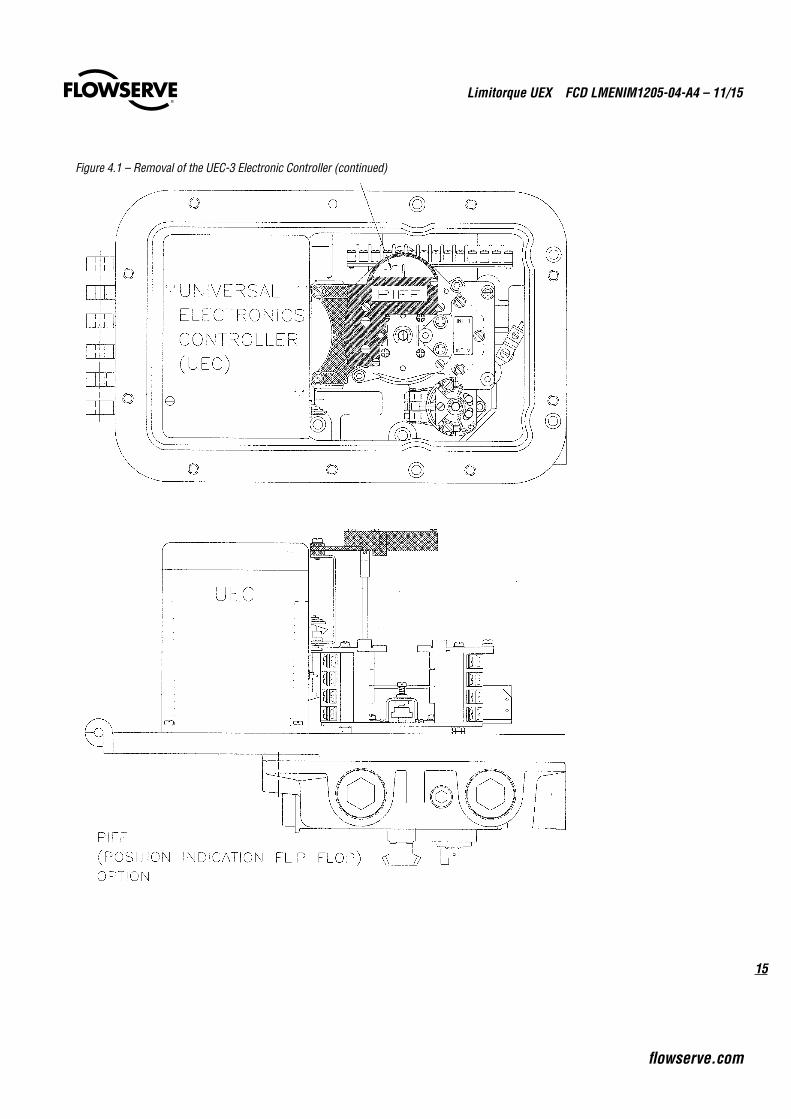
Figure 4.1 – Removal of the UEC-3 Electronic Controller (continued)
Limitorque UEX FCD LMENIM1205-04-A4 – 11/15
16
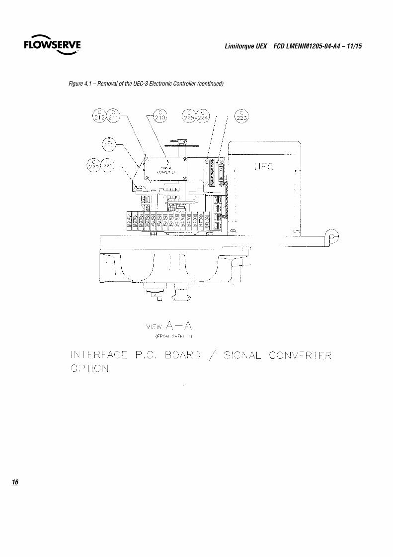
Figure 4.1 – Removal of the UEC-3 Electronic Controller (continued)
17
Limitorque UEX FCD LMENIM1205-04-A4 – 11/15
flowserve.com
HEATER MOTOR SUPPLY
FUSE FUSE
B-E ELEC
AA
SECTIO
N A
-A
BB
VIEW C
-Cc
c
ITEM1
DESC
RIPTION
QT
Y.1
REVERSING
CON
TAC
TOR
POW
ER SUPPLY BO
ARD
12
HARNESS, ICB TO D. BOARD
13
GRO
UN
D W
IRE, POW
ER1
41
5
HA
RNESS, RIBBO
N 50PIN
17
BRAC
KET, TRAN
SFORM
ER1
8
DAUGHTER BOARD (DDC ONLY)1
9
HA
RNESS, STA
RTER
111
INTERCONNECT BD (DDC SHOWN)
112
SBC W
/ CIRC
UIT TRA
CE
113
HA
RNESS, PO
WER
16
MO
V SNU
BBER, 12A/25A
110
RA
IL, DIN
114
STICKER, U
EC-3 A
LL1
15H
ARN
ESS, CO
NTA
CTO
R1
16
INSU
LATOR, SBC
118
SCREEN
PLATE1
19
LABEL, FRO
NT C
OV
ER1
20
INSU
LATOR, IC
B1
17
TERMIN
AL C
OV
ER, UEC
121
CON
TROL BO
X, U
EC1
22
LOC
KWA
SHER (IN
T TOO
TH)
224
HEX N
UT
25
HEX N
UT
126
123
SCREW
, PAN
HD
227
129
130
331
1DDC/4 UEC28
FRON
T COVER, U
EC
134
835
136
233
SCR
EW, P
T FLAT
SCREW
, PT OVA
L HD
BITBUS/M
OD
BUS PRO
M
132
12
2
5
16
14
1918
23
153620
9
35
11
3
2221
1
2724
3310
FUSE
4
8
2531
35
6
30
31
SCREW
, PAN
HD
SCREW
, PAN
HD
SCREW
, PAN
HD
SCREW
, PAN
HD
HA
RNESS, H
EATER
ON
CLEA
RPLA
STIC C
OV
ER
FUSES
137
SCREW
, PAN
HD
LOC
KWA
SHER (IN
T TOO
TH)
5DDC/4 UECLO
CKW
ASH
ER (EXT TO
OTH
)
INSU
LATOR BEH
IND
PCB
17
3729
3225
2813
34
25
2526
3125
RIBBON
FOR SW
93O
N BO
M 4805-455
7
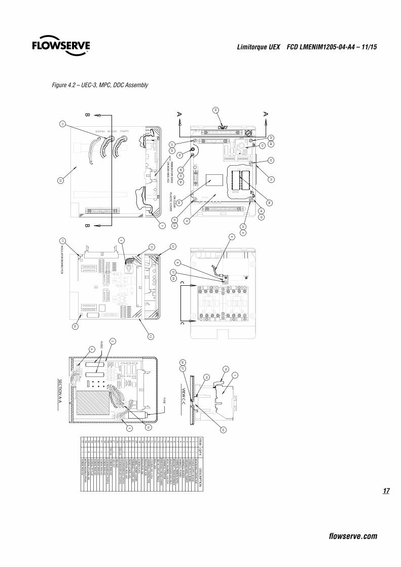
Figure 4.2 – UEC-3, MPC, DDC Assembly
Limitorque UEX FCD LMENIM1205-04-A4 – 11/15
18
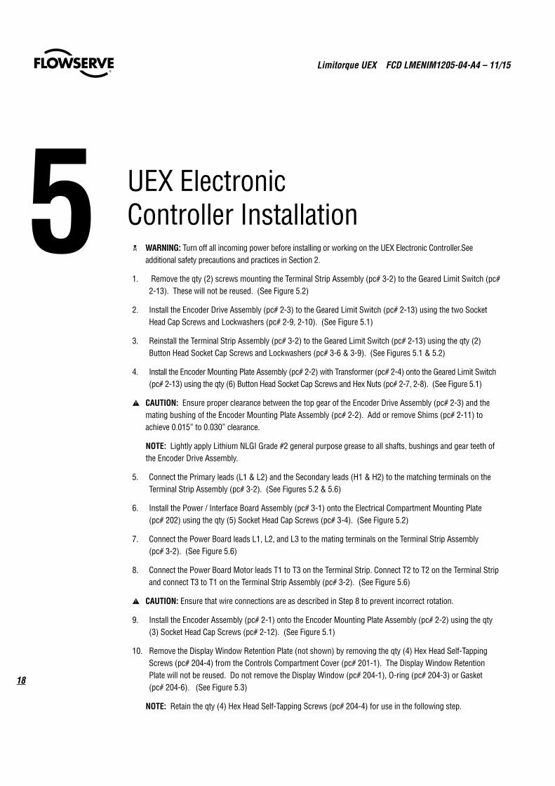
c WARNING: Turn off all incoming power before installing or working on the UEX Electronic Controller.See additional safety precautions and practices in Section 2.
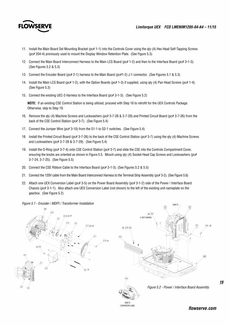
1. Remove the qty (2) screws mounting the Terminal Strip Assembly (pc# 3-2) to the Geared Limit Switch (pc# 2-13). These will not be reused. (See Figure 5.2)
2. Install the Encoder Drive Assembly (pc# 2-3) to the Geared Limit Switch (pc# 2-13) using the two Socket Head Cap Screws and Lockwashers (pc# 2-9, 2-10). (See Figure 5.1)
3. Reinstall the Terminal Strip Assembly (pc# 3-2) to the Geared Limit Switch (pc# 2-13) using the qty (2) Button Head Socket Cap Screws and Lockwashers (pc# 3-6 & 3-9). (See Figures 5.1 & 5.2)
4. Install the Encoder Mounting Plate Assembly (pc# 2-2) with Transformer (pc# 2-4) onto the Geared Limit Switch (pc# 2-13) using the qty (6) Button Head Socket Cap Screws and Hex Nuts (pc# 2-7, 2-8). (See Figure 5.1)
a CAUTION: Ensure proper clearance between the top gear of the Encoder Drive Assembly (pc# 2-3) and the mating bushing of the Encoder Mounting Plate Assembly (pc# 2-2). Add or remove Shims (pc# 2-11) to achieve 0.015” to 0.030” clearance.
NOTE: Lightly apply Lithium NLGI Grade #2 general purpose grease to all shafts, bushings and gear teeth of the Encoder Drive Assembly.
5. Connect the Primary leads (L1 & L2) and the Secondary leads (H1 & H2) to the matching terminals on the Terminal Strip Assembly (pc# 3-2). (See Figures 5.2 & 5.6)
6. Install the Power / Interface Board Assembly (pc# 3-1) onto the Electrical Compartment Mounting Plate (pc# 202) using the qty (5) Socket Head Cap Screws (pc# 3-4). (See Figure 5.2)
7. Connect the Power Board leads L1, L2, and L3 to the mating terminals on the Terminal Strip Assembly (pc# 3-2). (See Figure 5.6)
8. Connect the Power Board Motor leads T1 to T3 on the Terminal Strip. Connect T2 to T2 on the Terminal Strip and connect T3 to T1 on the Terminal Strip Assembly (pc# 3-2). (See Figure 5.6)
a CAUTION: Ensure that wire connections are as described in Step 8 to prevent incorrect rotation.
9. Install the Encoder Assembly (pc# 2-1) onto the Encoder Mounting Plate Assembly (pc# 2-2) using the qty (3) Socket Head Cap Screws (pc# 2-12). (See Figure 5.1)
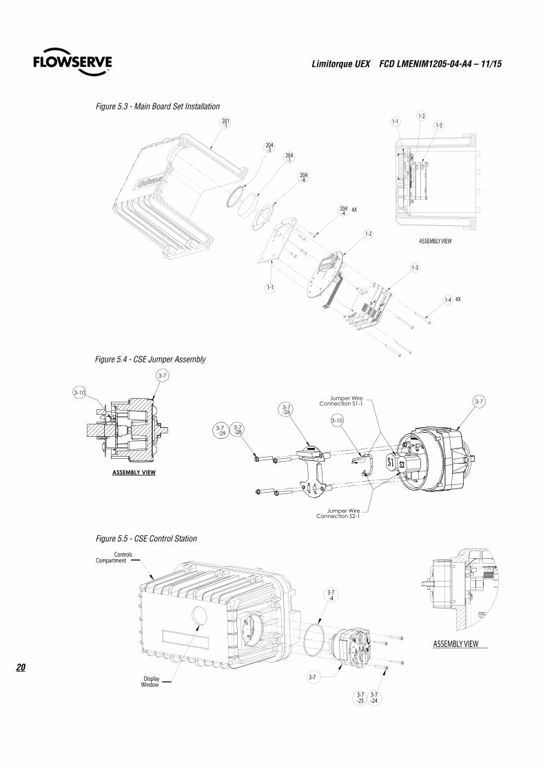
10. Remove the Display Window Retention Plate (not shown) by removing the qty (4) Hex Head Self-Tapping Screws (pc# 204-4) from the Controls Compartment Cover (pc# 201-1). The Display Window Retention Plate will not be reused. Do not remove the Display Window (pc# 204-1), O-ring (pc# 204-3) or Gasket (pc# 204-6). (See Figure 5.3)
NOTE: Retain the qty (4) Hex Head Self-Tapping Screws (pc# 204-4) for use in the following step.
5 UEX Electronic Controller Installation
19
Limitorque UEX FCD LMENIM1205-04-A4 – 11/15
flowserve.com
11. Install the Main Board Set Mounting Bracket (pc# 1-1) into the Controls Cover using the qty (4) Hex Head Self-Tapping Screws (pc# 204-4) previously used to mount the Display Window Retention Plate. (See Figure 5.3)
12. Connect the Main Board Interconnect Harness to the Main LCS Board (pc# 1-2) and then to the Interface Board (pc# 3-1-3). (See Figures 5.2 & 5.3)
13. Connect the Encoder Board (pc# 2-1) harness to the Main Board (pc#1-2) J-1 connector. (See Figures 5.1 & 5.3)
14. Install the Main LCS Board (pc# 1-2), with the Option Boards (pc# 1-3) if supplied, using qty (4) Pan Head Screws (pc# 1-4). (See Figure 5.3)
15. Connect the existing UEC-3 Harness to the Interface Board (pc# 3-1-3). (See Figure 5.2)
NOTE: If an existing CSE Control Station is being utilized, proceed with Step 16 to retrofit for the UEX Controls Package. Otherwise, skip to Step 19.
16. Remove the qty (4) Machine Screws and Lockwashers (pc# 3-7-28 & 3-7-29) and Printed Circuit Board (pc# 3-7-26) from the back of the CSE Control Station (pc# 3-7). (See Figure 5.4)
17. Connect the Jumper Wire (pc# 3-10) from the S1-1 to S2-1 switches. (See Figure 5.4)
18. Install the Printed Circuit Board (pc# 3-7-26) to the back of the CSE Control Station (pc# 3-7) using the qty (4) Machine Screws and Lockwashers (pc# 3-7-28 & 3-7-29). (See Figure 5.4)
19. Install the O-Ring (pc# 3-7-4) onto CSE Control Station (pc# 3-7) and slide the CSE into the Controls Compartment Cover, ensuring the knobs are oriented as shown in Figure 5.5. Mount using qty (4) Socket Head Cap Screws and Lockwashers (pc# 3-7-24, 3-7-25). (See Figure 5.5)
20. Connect the CSE Ribbon Cable to the Interface Board (pc# 3-1-3). (See Figures 5.2 & 5.5)
21. Connect the 120V cable from the Main Board Interconnect Harness to the Terminal Strip Assembly (pc# 3-2). (See Figure 5.6)
22. Attach one UEX Conversion Label (pc# 3-5) on the Power Board Assembly (pc# 3-1-2) side of the Power / Interface Board Chassis (pc# 3-1-1). Also attach one UEX Conversion Label (not shown) to the left of the existing unit nameplate on the gearbox. (See Figure 5.2)
Figure 5.1 - Encoder / MDPI / Transformer Installation
Figure 5.2 - Power / Interface Board Assembly
2-3
2-2
2-1
2-12 3X
2-4
2-62X
2-5 2X
2-9 2-10
2-11
2-13
2X
202
2-7 2-8 6X
2-1
2-22-3
2-4
VIEW 'A'
3-43X
3-4 2X
3-2
3-1-1
3-1-3
3-1-2
(1 NOT SHOWN)
3-63-9
202
2X
3-5
VIEW 'A'CONVERSION LABEL
Limitorque UEX FCD LMENIM1205-04-A4 – 11/15
20
Figure 5.4 - CSE Jumper Assembly
Figure 5.3 - Main Board Set Installation
3-7-4
ControlsCompartment
DisplayWindow
3-7-24
3-7-25
3-7
ASSEMBLY VIEW
Figure 5.5 - CSE Control Station
1-3
1-2
1-1
201-1
204-3
204-1
204-6
204-4 4X
1-4 4X
1-11-2
1-3
ASSEMBLY VIEW
3-7Jumper Wire
Connection S1-1
-28
-26
Jumper Wire Connection S2-1
3-73-7-29
3-7
3-10
3-10
ASSEMBLY VIEW
3-7
21
Limitorque UEX FCD LMENIM1205-04-A4 – 11/15
flowserve.com
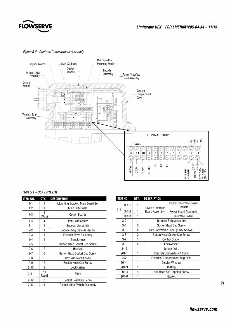
Table 5.1 – UEX Parts List
ITEM NO. QTY. DESCRIPTION1-1 1 Mounting Bracket, Main Board Set1-2 1 Main LCS Board
1-3 4 (Max) Option Boards
1-4 4 Pan Head Screw2-1 1 Encoder Assembly2-2 1 Encoder Mtg Plate Assembly2-3 1 Encoder Drive Assembly2-4 1 Transformer2-5 2 Button Head Socket Cap Screw2-6 2 Hex Nut2-7 6 Button Head Socket Cap Screw2-8 6 Hex Nut (Not Shown)2-9 2 Socket Head Cap Screw2-10 2 Lockwasher
2-11 As Req'd Shim
2-12 3 Socket Head Cap Screw2-13 1 Geared Limit Switch Assembly
ITEM NO. QTY. DESCRIPTION
3-13-1-1 1
Power / Interface Board Assembly
Power / Interface Board Chassis
3-1-2 1 Power Board Assembly3-1-3 1 Interface Board
3-2 1 Terminal Strip Assembly3-4 5 Socket Head Cap Screw3-5 2 Uex Conversion Label (1 Not Shown)3-6 2 Button Head Socket Cap Screw3-7 1 Control Station3-9 2 Lockwasher3-10 1 Jumper Wire201-1 1 Controls Compartment Cover202 1 Electrical Compartment Mtg Plate
204-1 1 Display Window204-3 1 O-Ring204-4 4 Hex Head Self-Tapping Screw204-6 1 Gasket
12 1234567891011
GREEN
TERMINAL STRIP
GN
/YL
(L2)
YL
(L1)
RD
(L3)
BL T3 T2
T1
(10-
2)RD
H1
110V
AC
N
H2 H
2
MTR
. HTR
.H
2
1/2
110V
AC
HO
T
MTR
. HTR
.
(10-
1)RD
3/4
Figure 5.6 - Controls Compartment Assembly
Main LCS Board
DisplayWindow
Main Board SetMounting Bracket
EncoderAssemblyEncoder Drive
Assembly Power / InterfaceBoard Assembly
ControlsCompartmentCover
ControlStation
Option Boards
Terminal StripAssembly
Limitorque UEX FCD LMENIM1205-04-A4 – 11/15
22
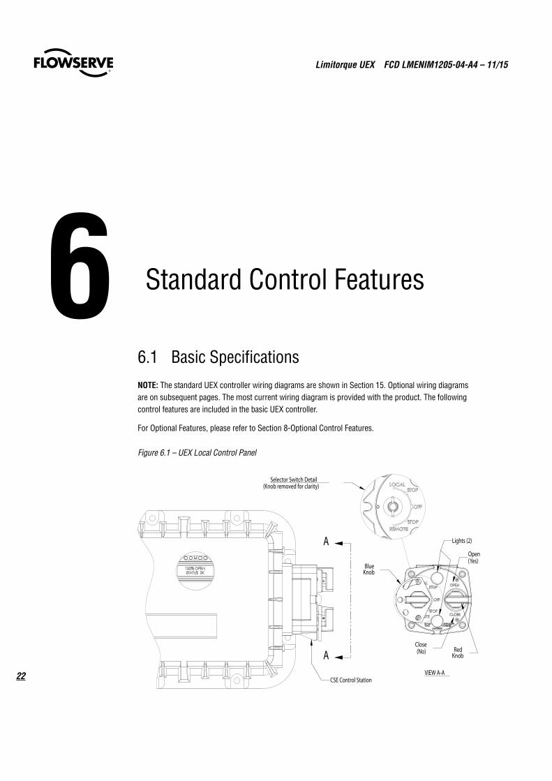
6.1 Basic SpecificationsNOTE: The standard UEX controller wiring diagrams are shown in Section 15. Optional wiring diagrams are on subsequent pages. The most current wiring diagram is provided with the product. The following control features are included in the basic UEX controller.
For Optional Features, please refer to Section 8-Optional Control Features.
Figure 6.1 – UEX Local Control Panel
6 Standard Control Features
VIEW A-A
BlueKnob
RedKnob
Open(Yes)
Close(No)
Lights (2)
CSE Control Station
Selector Switch Detail(Knob removed for clarity)
A
A
23
Limitorque UEX FCD LMENIM1205-04-A4 – 11/15
flowserve.com
6.2 Local ControlThe Control Panel includes a red Local/Stop/Remote selector switch (padlockable in all three positions; a ¼" (6 mm) hasp is recommended) and a black Open/Close rotary switch (spring-return to center). The Open and Close switches may be configured to allow either push-to-run (inching) control or maintained control.
Local IndicationThe Control Panel includes the following:
• 32-character graphical LCD
Displays valve position as “PERCENT OPEN” and the current actuator status.
• Red/Green LED Indicators – the color assignment for the red and green LEDs is reversible as standard.
Red ON = Valve fully open
Red “BLINKING” = Valve opening
Green “BLINKING” = Valve closing
Green ON = Valve fully closed
• Yellow LED
Yellow ON = Actuator available for remote operation,
= Valve stopped in Intermediate position.
Yellow “BLINKING” = Monitor Relay de-energized, actuator not available for remote operation.
NOTE: For UEX packages supplied without the encoder, position indication on the LCD display or remotely is not available.
6.3 Remote Control Modes of OperationThe actuator may be controlled remotely by two, three or four wires.
• Four-Wire Control – Three momentary contacts. Valve can be opened, closed or stopped.
• Two-Wire Control – Single open or closed contact. Valve can be opened or closed, but not stopped in mid-travel.
• Three-Wire Maintained – Two momentary contacts for self-maintained control. Valve can be opened or closed but not stopped in mid-travel.
• Three-Wire Inching – Two “push-to-run” contacts. Valve can be opened, closed and stopped in mid-travel.
Refer to Figure 15.4 for remote wiring connections.
Limitorque UEX FCD LMENIM1205-04-A4 – 11/15
24
Remote Control TypeThe actuator may be placed in digital only, modulation only, network only, or multi-command types.
• Digital (Discrete) Only Control Type – Only digital input commands are recognized and acted upon. All other types of remote control commands are ignored.
• Analog (Modutronic) Only Control Type – Only Modutronic 4-20 mA commands are recognized and acted upon. All other types of remote control commands are ignored.
• Network Only Control Type – Only network (DDC, Fieldbus, Profibus, Device Net) commands are recognized and acted upon. All other types of remote control commands are ignored.
• Multi-control Mode Operation - there are three modes of remote control when remote mode is configured for multi control: digital control, analog control, and network control. Digital and network control operation is based on the last command received. Analog operation is initiated by either toggling user input 2 (configure for CSE input) or breaking and reapplying the analog control.
Remote Control Signal PowerPower for remote control signals may be derived internally from the actuator or provided externally by the user. Signals can range from 24 to 125 VAC or VDC.
External Power SupplyAn external power supply in the range of 12 to 24 VDC may be provided by the user with the optional UPS board.
Standard Internal Power SupplyThe standard internal signal supply is 24 VDC. The 24 VDC supply offers a maximum loading of 5 W. The 24 VDC supply, in conjunction with the opto-isolated digital inputs, allows control from remote volt-free contacts over long distances and simplifies the user’s control scheme. Standard control employs a negative earth. Positive earth (negative switching) is available by wiring to the (+) positive common as shown on the wiring diagrams.
6.4 Emergency Shutdown (ESD)Up to three independent ESD signals may be applied, prioritized and configured for different actions for the ESD event associated with each. Either of these ESD signals may be applied to the actuator to override any existing command signal and send the valve to its preselected shutdown position, providing the actuator is in Remote mode (default configuration for ESD is “Ignore, take no action”). Any new command signal will be ignored until the ESD signal is removed. During setup, the actuator may be configured to close, open, stop, take no action, or “move to a previously configured position” on receipt of the ESD signal. The ESD action may also be configured to override any inhibit signal, the local selector switch, the local stop switch, an overtorque condition, lost phase, or jammed valve protection. Motor thermal protection may be bypassed for critical ESD applications in non-hazardous or special service locations. Disabling the motor thermostat voids all third-party certifications, including Factory Mutual and CSA.
25
Limitorque UEX FCD LMENIM1205-04-A4 – 11/15
flowserve.com
6.5 Remote External Interlocks/InhibitsThree user-defined inputs are provided for the connection of remote contacts that will prevent motor-ized operation of the actuator. These are effective in both Remote and Local modes and may only be overridden by a maintained ESD signal, if so configured (refer to Figure 15.1 for wiring connections). For ESD connections, the user may select either a single common or isolated commons.
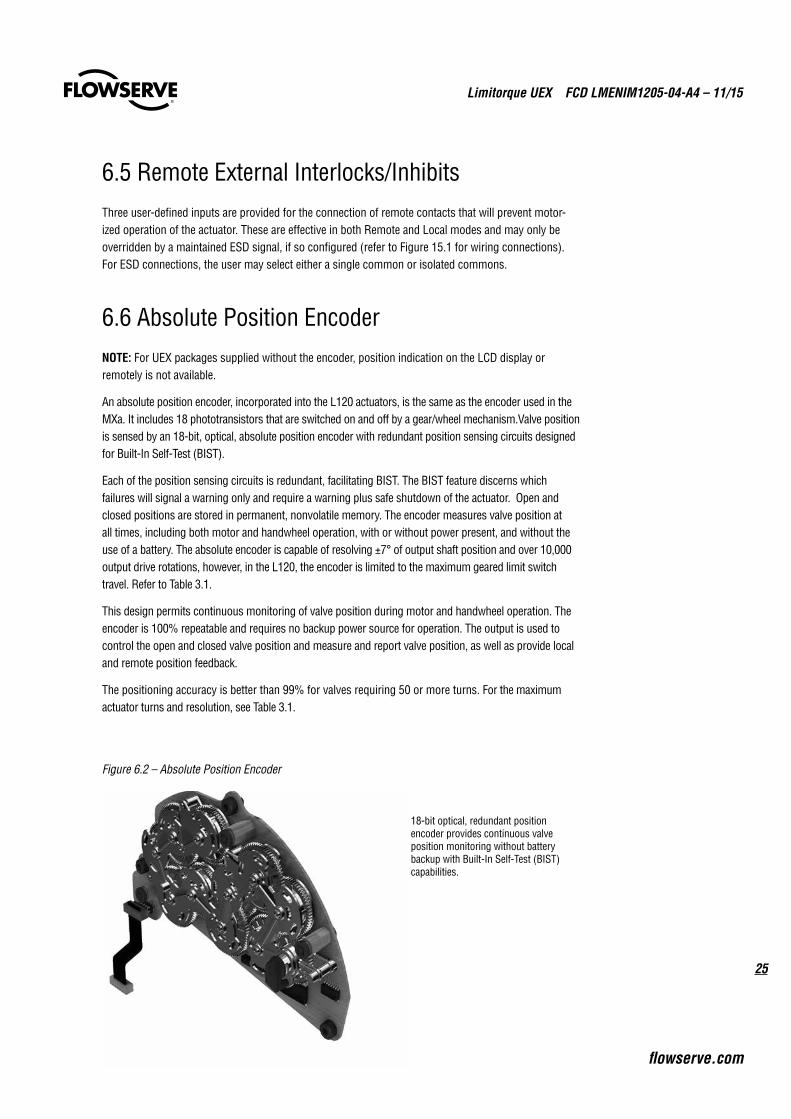
6.6 Absolute Position EncoderNOTE: For UEX packages supplied without the encoder, position indication on the LCD display or remotely is not available.
An absolute position encoder, incorporated into the L120 actuators, is the same as the encoder used in the MXa. It includes 18 phototransistors that are switched on and off by a gear/wheel mechanism.Valve position is sensed by an 18-bit, optical, absolute position encoder with redundant position sensing circuits designed for Built-In Self-Test (BIST).
Each of the position sensing circuits is redundant, facilitating BIST. The BIST feature discerns which failures will signal a warning only and require a warning plus safe shutdown of the actuator. Open and closed positions are stored in permanent, nonvolatile memory. The encoder measures valve position at all times, including both motor and handwheel operation, with or without power present, and without the use of a battery. The absolute encoder is capable of resolving ±7° of output shaft position and over 10,000 output drive rotations, however, in the L120, the encoder is limited to the maximum geared limit switch travel. Refer to Table 3.1.
This design permits continuous monitoring of valve position during motor and handwheel operation. The encoder is 100% repeatable and requires no backup power source for operation. The output is used to control the open and closed valve position and measure and report valve position, as well as provide local and remote position feedback.
The positioning accuracy is better than 99% for valves requiring 50 or more turns. For the maximum actuator turns and resolution, see Table 3.1.
Figure 6.2 – Absolute Position Encoder
18-bit optical, redundant position encoder provides continuous valve position monitoring without battery backup with Built-In Self-Test (BIST) capabilities.

Limitorque UEX FCD LMENIM1205-04-A4 – 11/15
26
7 Protection Features
7.1 Autophase Protection and CorrectionThe phase rotation of the incoming three-phase supply is continuously monitored. In the event that field wiring is reversed, UEX controls automatically correct to ensure the valve operates in the commanded direction. In addition, the detector circuit monitors the presence of all three phases. If a phase is lost, valve starting will be prevented and the user alerted via an LCD error message and Monitor Relay Alarm.
7.2 Jammed Valve ProtectionIf the actuator cannot overcome the required valve starting torque, a jammed valve condition occurs. Jammed valve protection senses the lack of valve movement and initiates a brief reverse/forward cycle to free the valve. If this is unsuccessful, further electrical operation is prevented and the monitor relay is signaled.
7.3 Instantaneous Reversal ProtectionThe control logic incorporates a brief time delay (from 0.5 to 1.0 seconds) between motor reversals. This reduces motor current surges and prolongs the life of the contactor. Note: It is not necessary to switch to STOP before reversing the actuator.
7.4 Motor Thermal ProtectionThe motor is protected against overheating by a thermal OL in the motor enclosure. Thermal cutout threshold is set for 120˚C (Class B). Options are available for other classifications.
a CAUTION: Confirm that motor thermals are rated no higher than 120°C for Explosionproof service.
27
Limitorque UEX FCD LMENIM1205-04-A4 – 11/15
flowserve.com
8.1 ModutronicNOTE: For UEX packages supplied without the encoder, modulating control and position indication are not available.
The Modutronic controller will alter valve position in proportion to an analog command signal. It includes an automatic pulsing mode to reduce overshoot at the set point.
The following parameters may be easily set during the configuration of the unit:
• Proportional Band range from 2% to 100% (15% = default)
• Dead Band range from ± 1% to 50% (2% = default)
• Polarity 20 mA = OPEN (default) or 20 mA = CLOSE
• Action on loss of command signal OPEN, CLOSE, STOP (CLOSE = default), or Move-to a previously configured position
• Delay after stop 0–60 seconds (0 = default)
• Command Signal
• 4–20 mA
• Input impedance - 150 ohms
Repeatability – The Modutronic is repeatable to within ±1 % for 60 seconds stroke time or longer, and 2% for 30 to 60 seconds.. Repeatability is defined as encoder feedback position versus position command. Overall valve and actuator system accuracy depends on many factors, including actuator gearing backlash and valve/actuator coupling tolerance, and therefore cannot be defined by this document.
Extrema Mode – If the command signal represents a position of 0–2% OPEN (nominal 4.00–4.32 mA) or 98–100% OPEN (nominal 19.68–20.00 mA), then the UEX/L120 will move the valve directly to that position, without pulsing.
8 Optional Control Features
Limitorque UEX FCD LMENIM1205-04-A4 – 11/15
28
Positioning Frequency – The standard frequency is suitable for a rate of 600 starts/hour for short periods, typical of process start-up. Typical process control of ≤ 100 starts/hour.
8.2 Analog Position Transmitter (APT)The APT is an internally powered, non-contacting valve position transmitter. The isolated output signal is proportional to the position of the valve and is available as 4–20 mA and/or 0-20 mA, 0-10 VDC, 2-10 VDC, 0-5 VDC, or 1-5 VDC.
The user may select the minimum signal to represent either the fully OPEN or the fully CLOSE position of the valve during the setup procedure.
• Accuracy = 99% of full scale value (for Drive Sleeve Turns > 50)
• Non-Linearity = ± 1% of full scale value
• Impedance = 0–600 ohms (4–20 mA signal)
• Minimum external load = 1000 ohms (0–10 VDC signal)
8.3 Two-Speed Timer A two-speed pulsing timer can be enabled to extend the operating time in the close and/or the open directions. Pulsing may be applied from 0.5 (if precision is set to xxx.x%) to 99% of full valve travel or to a small portion. The ON pulsing cycle is configurable from 0.5 to 20 seconds in 0.5 second incre-ments, and the OFF pulsing cycle is configurable from 1.0 to 200 seconds in 1 second increments. The two-speed timer is especially effective where concerns of hydraulic shock exist.
8.4 Control Station (CSE)The CSE is a separate control station designed for the operation of inaccessible actuators. It is available with LEDs, Remote/Local and Open/Close selector switches. The CSE may be powered by the actuator internal supply, provided wire resistance and other external loads do not limit the available signal power presented to the UEX.

29
Limitorque UEX FCD LMENIM1205-04-A4 – 11/15
flowserve.com
The UEX provides a comprehensive network option portfolio to the user. Network solutions are improved for the user that has an L120 with UEC, with the addition of DeviceNet to complement Modbus, Foundation Fieldbus H1, Profibus DP_V1 and Profibus PA. UEX provides the user with predictable, reliable, and safe operation for years to come, in applications which are subject to the most rigorous requirements and environmental extremes.
With each of the provided network protocols a user may configure the unit to move to a predefined fail-safe position on loss of communication. Action on loss of command signal OPEN, CLOSE, STOP, or MOVE-TO preconfigured position. The user may also configure the length of time communication must be lost before the unit indicates communication loss and performs the communication loss action.
NOTE: For UEX packages supplied without the encoder, network control and position indication are not available.
9.1 Modbus™
Modbus™ provides the ability to control and monitor up to 250 actuators over a single twisted-pair cable. The communication network employs Modbus™ protocol on an RS-485 network and is redun-dant. Redundancy assures that any single break or short in the communication cable will not disable any actuators. Each actuator has included an addressable field unit that communicates over the twisted pair network and executes open, close, stop, ESD, and GO TO position commands. The field unit also communicates all actuator status and alarm diagnostic messages over the same communication network.
Modbus Network• Single-ended loop (as standard – See Figure 16.1)
• Modbus protocol
• High speed – up to 19.2K baud
9 Network Communications
Limitorque UEX FCD LMENIM1205-04-A4 – 11/15
30
9.2 Master Station IIIL120 actuators equipped with Modbus can be controlled via Flowserve Limitorque’s Master Station II or III.
The next-generation master station is designed specifically for use with Limitorque’s line of DDC (Modbus) electric actuators. The Master Station III acts as a single-source controller for up to 250 actuators.
The Master Station III is a plug-and-play solution that provides complete control and diagnostics for Limitorque field units through a simple touch-panel operator interface. The key features of the Master Station III include:
• A network time protocol to allow for time synchronization of alarms/diagnostic data to Host device
• Multilingual support includes English, Spanish, German, French, Italian
• Asset management and diagnostic via Bluetooth V2.0+ Enhanced Data Rate (EDR) Class 100m
• Configuration of slave register polling schedule
• Industry standard Modbus RTU, ASCI, UDPor TCP/IP protocols
• Three levels of user password protection
• 5.6” TFT touch-screen display
• E-mail notification of configurable alarm conditions
• Data/event logging
• Network control of up to 250 devices
• Front access to peripheral ports: Ethernet, USB x 2, VGA, printer/debug
• Modular hot-swappable redundant design
• Built-in secure Web server for control, monitoring and asset management capabilities
9.3 Foundation Fieldbus CommunicationL120 actuators can be fitted with Foundation Fieldbus protocol that complies with the IEC 61158-2 Fieldbus H1 standard. The field unit device is able to support several topologies, such as, point-to-point, bus with spurs, daisy chain, tree, or a combination of these. The FF device has network features that include:
• Link Active Scheduler that controls the system
• High-speed communications at to 31.25 kbits/sec
• Publisher - subscriber communication
• One analog input block, one analog output block, two discrete output function blocks, Transducer block, Resource block, and four discrete input function blocks
• PID (proportional integral derivative) loop control
• Device descriptions
• Configurable by user
Link Active Scheduler communication: Fieldbus segments have one active Link Active Scheduler (LAS) at a given time, which is the bus arbiter, and does the following:
31
Limitorque UEX FCD LMENIM1205-04-A4 – 11/15
flowserve.com
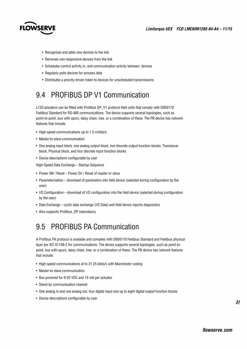
• Recognizes and adds new devices to the link
• Removes non-responsive devices from the link
• Schedules control activity in, and communication activity between, devices
• Regularly polls devices for process data
• Distributes a priority-driven token to devices for unscheduled transmissions
9.4 PROFIBUS DP V1 Communication L120 actuators can be fitted with Profibus DP_V1 protocol field units that comply with EN50170 Fieldbus Standard for RS-485 communications. The device supports several topologies, such as, point-to-point, bus with spurs, daisy chain, tree, or a combination of these. The PB device has network features that include:
• High-speed communications up to 1.5 m/bits/s
• Master-to-slave communication
• One analog input block, one analog output block, two discrete output function blocks, Transducer block, Physical block, and four discrete input function blocks
• Device descriptions configurable by user
High-Speed Data Exchange – Startup Sequence
• Power ON / Reset – Power On / Reset of master or slave
• Parameterization – download of parameters into field device (selected during configuration by the user)
• I/O Configuration – download of I/O configuration into the field device (selected during configuration by the user)
• Data Exchange – cyclic data exchange (I/O Data) and field device reports diagnostics
• Also supports Profibus_DP redundancy
9.5 PROFIBUS PA Communication A Profibus PA protocol is available and complies with EN50170 Fieldbus Standard and Fieldbus physical layer per IEC 61158-2 for communications. The device supports several topologies, such as point-to-point, bus with spurs, daisy chain, tree, or a combination of these. The PB device has network features that include:
• High-speed communications at to 31.25 kbits/s with Manchester coding
• Master-to-slave communication
• Bus powered for 9-32 VDC and 15 mA per actuator
• Stand-by communication channel
• One analog in and one analog out, four digital input and up to eight digital output function blocks
• Device descriptions configurable by user
Limitorque UEX FCD LMENIM1205-04-A4 – 11/15
32
9.6 DeviceNetDeviceNet complies with CAN based protocol and provides the following features:
• DeviceNet Group 2 Server implementation.
• Bus Powered Network Interface allows power alarm information to be communicated when actuator loses main power. The actuator does NOT drop off the network when 3-phase power is lost.
• Standard Polled I/O Connection
• Standard Bit Strobed I/O Connection
• Standard Change of State / Cyclic I/O Connection
• Standard explicit connections defined as:
• Various Assembly Objects and sizes that allow the network user to determine how much data to transfer to accommodate network installation data throughput requirements.
• Automatic BAUD rate detection.
• Node Address configurable via local setup menu, or via the remote network user.
• Broadcast or group network originated ESD support.
The following commands and information may be transmitted over the DeviceNet network:
• “OPEN,” “STOP,” and “CLOSE” commands
• “ESD” and “MOVE–TO” position commands
• Actuator status and alarm messages
• Four digital inputs, two digital outputs, one analog input and one analog output for user configuration
• A surge-protected and isolated communication channels
• UEX control panel configuration
Please see Section 16 for network connection topologies and cabling recommendations.

33
Limitorque UEX FCD LMENIM1205-04-A4 – 11/15
flowserve.com
10.1 Local FeaturesLCD Displays – The LCD displays an array of data concerning the status of actuator components
in clear, graphical or textual language. The UEX is available with eleven languages: English, Spanish, German, French, Italian, Portuguese, Mandarin, Russian, Bahasa Indonesia, Turkish and Katakana.
Normal Display – The normal display illustrates current valve position and status. Alarm Functions – Alarm functions (active alarms will be toggled every four seconds)
that may be displayed include:
• Valve Jammed - Valve cannot start moving
• Lost Phase - One of three phases lost
• Motor Overtemp – Thermal overload exceeded
• Overtorque - Torque exceeded in mid-travel
• Hardware Failure - Indication
• Modbus, Profibus, Foundation Fieldbus, DeviceNet off - Enabled, but “OFF”
• ESD Active - ESD signal active
• Inhibit Active - Inhibit signal present
• No analog signal - 4–20 mA signal absent (Modutronic enabled, red selector switch in “REMOTE”)
• DDC, PB, FF, DNet comm. Loss – Enabled, signal absent
• Analog Output Loss - Enabled, but output current loop open
10 Monitoring and Diagnostic Features

Limitorque UEX FCD LMENIM1205-04-A4 – 11/15
34
10.2 DiagnosticsStandard Diagnostic Screens – Diagnostic screens may be accessed quickly through the Setup dialogue or the UEX Dashboard Software solutions package. These screens provide detailed data of actuator status. Included are:
• Hardware – status of electronic components such as thermistor, encoder, power board, DDC/FF/PB/DeviceNet network board, analog board, DIGIN and ANIN (digital in and analog in)
• Motor – Phase rotation
• Power Supply – Maximum and minimum voltage, frequency
• Identification – Tag number, serial number, order number, software revision
• View Network Status – Checks for Standby, Recoverable Fault, Nonrecoverable Fault, and View Network Status
• Operation Log – Actuator turns, contactor operations, motor run-time, stroke time, manual operations
• View Control Compartment Temperature (View Power Supply Menus)
35
Limitorque UEX FCD LMENIM1205-04-A4 – 11/15
flowserve.com
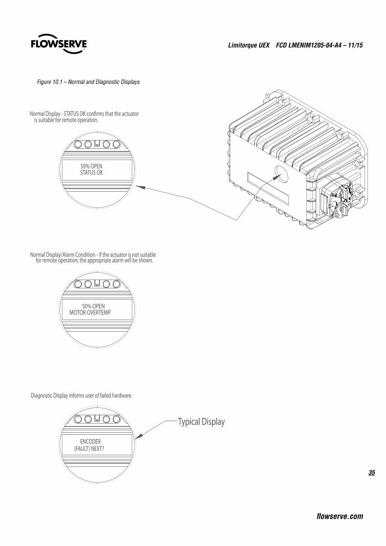
Figure 10.1 – Normal and Diagnostic Displays
50% OPENSTATUS OK
Normal Display - STATUS OK con�rms that the actuator is suitable for remote operation.
Typical Display
ENCODER(FAULT) NEXT?
Diagnostic Display informs user of failed hardware.
50% OPENMOTOR OVERTEMP
Normal Display/Alarm Condition - If the actuator is not suitable for remote operation, the appropriate alarm will be shown.

Limitorque UEX FCD LMENIM1205-04-A4 – 11/15
36
11 Remote Indication Features
11.1 Actuator Status Contacts (S1a, S1b, S2a, S2b)
Four latched contacts provide remote feedback of actuator status. Two (S1a, S2a) contacts may be individually configured for normally open, normally closed, or blinker (continuous opening and closing of the valve) operation and provide feedback of one of the functions listed below. Two other relays are complementary.
• Closed • Motor overtemp
• Closing • Overtorque
• Mid-travel • Open torque switch
• Opening • Close torque switch
• Open • ESD signal
• Stopped • Open inhibit
• Valve moving • Close inhibit
• Local selected • Lost phase
• Local STOP/OFF • No analog signal
• Manual operation • Hardware failure
• Valve jammed • Network controlled
• Remote selected • CSE controlled
37
Limitorque UEX FCD LMENIM1205-04-A4 – 11/15
flowserve.com
Recommended settings are:• S1a – Normally closed contact at valve fully CLOSE
• S1b – Normally closed contact at valve fully OPEN – Default position. See wiring diagram.
• S2a – Normally open contact at valve fully CLOSE
• S2b – Normally open contact at valve fully OPEN – Default position. See wiring diagram.
The standard contacts are rated for 2.0 A at 30 VDC and 0.5 A at 125 VAC.
11.2 Monitor Relay (RM)The monitor relay provides immediate indication of problems that prevent remote valve operation. It has a normally open contact and a normally closed contact (1 x SPDT contact) and is energized when the three-phase supply is present and the actuator is in a normal/healthy state.
The relay will de-energize if any of the following events occur:
• Loss of one or more phases of the three-phase power supply
• Loss of internal control supply
• Jammed valve detected
• Motor overtemp is active (unless thermostat is configured to OFF)
During configuration, the following parameters may be added to the monitor relay function:
• Selector switch is in “Local” mode
• Selector switch is in “Stop” position
• Overtorque
• Inhibit signal active
• ESD signal active (The user can enable or disable “local” mode and “stop” position. Default is enabled.)
The monitor relay resets when the faulty state is rectified. The standard contacts are rated for 5.0 A at 250 VAC, 30 VDC. The monitor relay can be disabled if the user chooses.
11.3 Exact End Position IndicationOn torque-seated valves, the end-of-travel indication switch trips when the required torque is achieved at the end of travel. This ensures that remote, self-latched signals will not be disconnected prematurely, and that the valve will be tightly seated.

Limitorque UEX FCD LMENIM1205-04-A4 – 11/15
38
12If the main three-phase power supply is not available during the configuration of the actuator, an optional module contains provisions for connecting a 24 VDC, 1 A power source to the auxiliary input terminals shown in the wiring diagram on the following pages. Power supply will draw up to 0.5 A.
Auxiliary Power Supply - Uninterruptible Power Supply (UPS) Connection
39
Limitorque UEX FCD LMENIM1205-04-A4 – 11/15
flowserve.com
The UEX is provided with isolated commons for control functions. Please refer to wiring diagram in Section 15 for locations.
13 Isolated Commons

Limitorque UEX FCD LMENIM1205-04-A4 – 11/15
40
14 Actuator Configuration
14.1 Local ConfigurationUEX controllers may be configured through the CSE control station switches, with settings visible on the LCD display. Settings that can be initiated or changed include:
• Direction of rotation
• Action on ESD
• External inhibits
• Remote control operating mode
• Motor thermostat action
• Stop valve on torque or position
• All optional features (Modutronic, Modbus, FF H1, PB-DPV1, PB-PA, DeviceNet, Timers, APT, etc.)
14.2 Default ConfigurationUnless otherwise specified, UEX controllers will be shipped with the following configuration, which becomes effective after the L120 limit switches are properly set.
• Open stop by limit
• Close stop by limit
• Maintained local controls
• Clockwise to close
• ESD is “off” and set to “IGNORE.”
• Inhibits enabled, turned “OFF”
• Remote control – three-wire maintained and Multi-mode
• Password – 100
• Modutronic Option (if installed)
41
Limitorque UEX FCD LMENIM1205-04-A4 – 11/15
flowserve.com
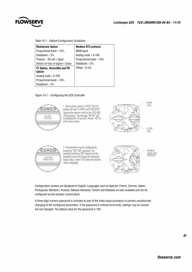
Table 14.1 – Default Configuration Guidelines
Modutronic OptionProportional band – 15%Deadband – 2%Polarity – 20 mA = OpenAction on loss of signal = Close
Modbus RTU protocol9600 baudAnalog scale = 0-100Proportional band – 15%Deadband – 2%Offset – 0 mAFF Option, DeviceNet and PB
OptionAnalog scale = 0-100Proportional band – 15%Deadband – 2%
Figure 14.1 – Configuring the UEX Controller
0% OPENSTATUS OK
1 Place selector switch in "STOP." The LCDdisplay will read "% OPEN" and "STATUS OK."Operate the selector switch to the (YES) (NO)(YES) positions. The message "SETUP?" willbe displayed for 10 seconds. Answer "YES" toenter setup routine.
50% OPENTORQUE VALUE
2 All parameters may be con�gured byanswering "YES"/"NO" questions. For example, entering a "NO" response to thedisplayed screen will change the displayedtorque value. Select "YES" when the desiredvalue is displayed.
KNOB INOPEN (YES)POSITION
OPEN(YES)
CLOSE(NO)
Configuration screens are displayed in English. Languages such as Spanish, French, German, Italian, Portuguese, Mandarin, Russian, Bahasa Indonesia, Turkish and Katakana are also available and can be configured via the actuator control panel.
A three-digit numeric password is included as part of the initial setup procedure to prevent unauthorized changing of the configured parameters. If the password is entered incorrectly, settings may be viewed, but not changed. The default value for the password is 100.
Limitorque UEX FCD LMENIM1205-04-A4 – 11/15
42
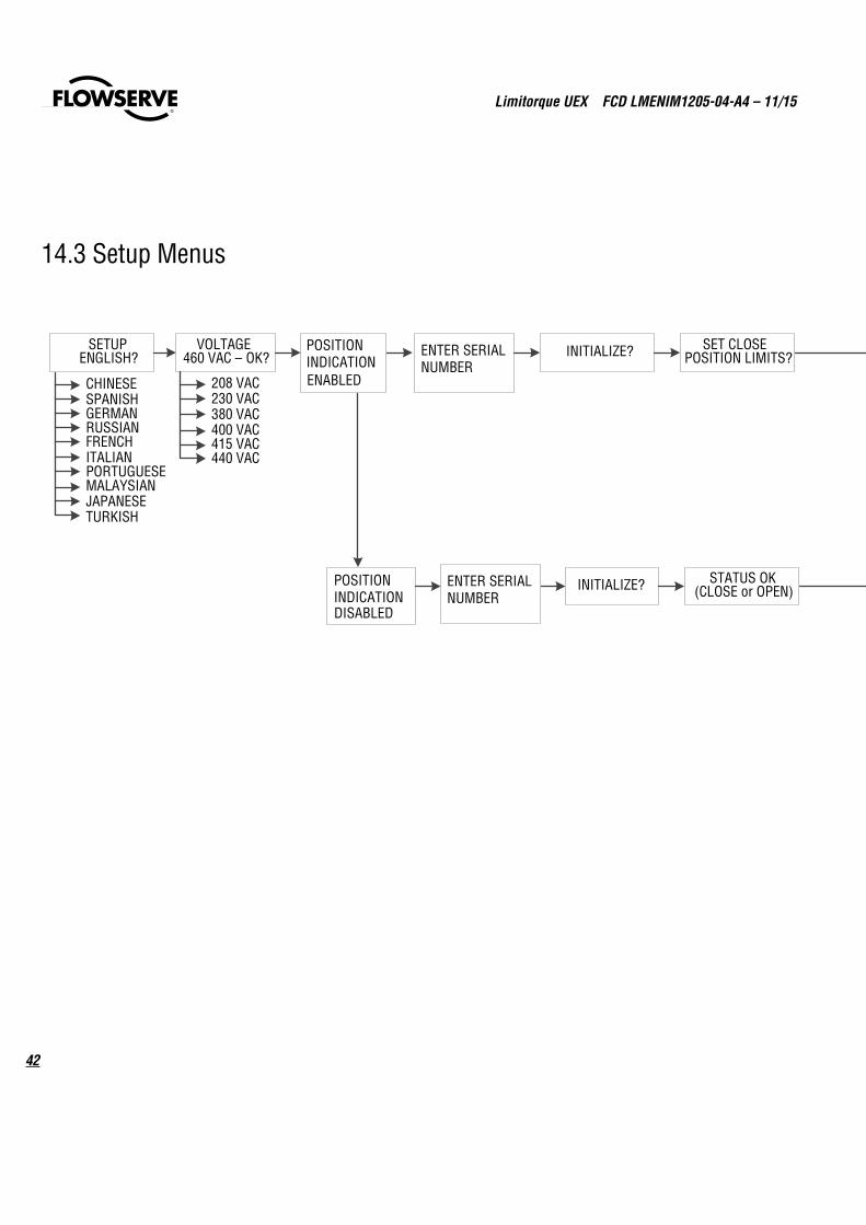
SETUPENGLISH?
VOLTAGE460 VAC – OK?
208 VAC230 VAC380 VAC400 VAC415 VAC440 VAC
POSITION INDICATIONENABLED VIEW SETTINGS
VIEW DIAGNOSTICS
INITIALIZE? SET CLOSE POSITION LIMITS?
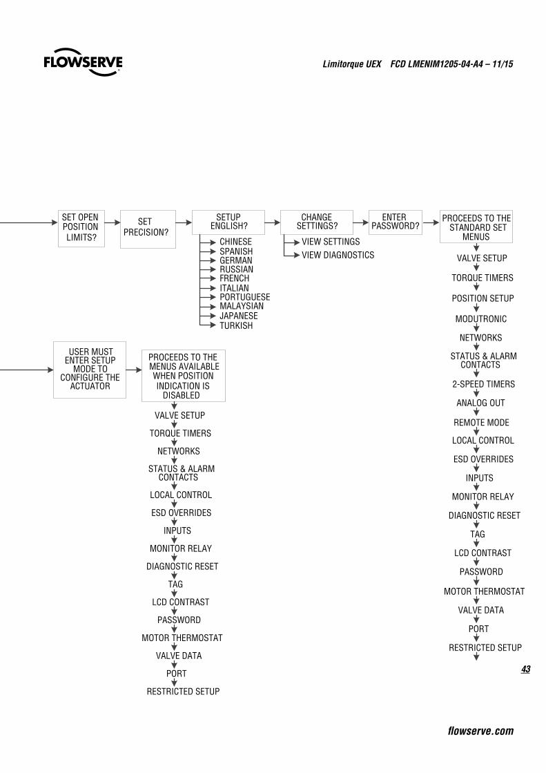
SET OPEN POSITION LIMITS?
SET PRECISION?
SETUPENGLISH?
CHINESESPANISHGERMANRUSSIANFRENCHITALIANPORTUGUESEMALAYSIANJAPANESETURKISH
CHANGESETTINGS?
ENTER PASSWORD?
PROCEEDS TO THE STANDARD SET
MENUS
ENTER SERIAL NUMBER
INITIALIZE? STATUS OK(CLOSE or OPEN)
PROCEEDS TO THE MENUS AVAILABLE WHEN POSITION INDICATION IS
DISABLED
VALVE SETUP
TORQUE TIMERS
POSITION SETUP
MODUTRONIC
NETWORKS
STATUS & ALARM CONTACTS
2-SPEED TIMERS
ANALOG OUT
REMOTE MODE
LOCAL CONTROL
ESD OVERRIDES
INPUTS
MONITOR RELAY
DIAGNOSTIC RESET
TAG
LCD CONTRAST
PASSWORD
MOTOR THERMOSTAT
VALVE DATA
PORT
RESTRICTED SETUP
USER MUST ENTER SETUP
MODE TO CONFIGURE THE
ACTUATOR
VALVE SETUP
TORQUE TIMERS
NETWORKS
STATUS & ALARM CONTACTS
LOCAL CONTROL
ESD OVERRIDES
INPUTS
MONITOR RELAY
DIAGNOSTIC RESET
TAG
LCD CONTRAST
PASSWORD
MOTOR THERMOSTAT
VALVE DATA
PORT
RESTRICTED SETUP
DISABLED
POSITION INDICATION
ENTER SERIAL NUMBER
CHINESESPANISHGERMANRUSSIANFRENCHITALIANPORTUGUESEMALAYSIANJAPANESETURKISH
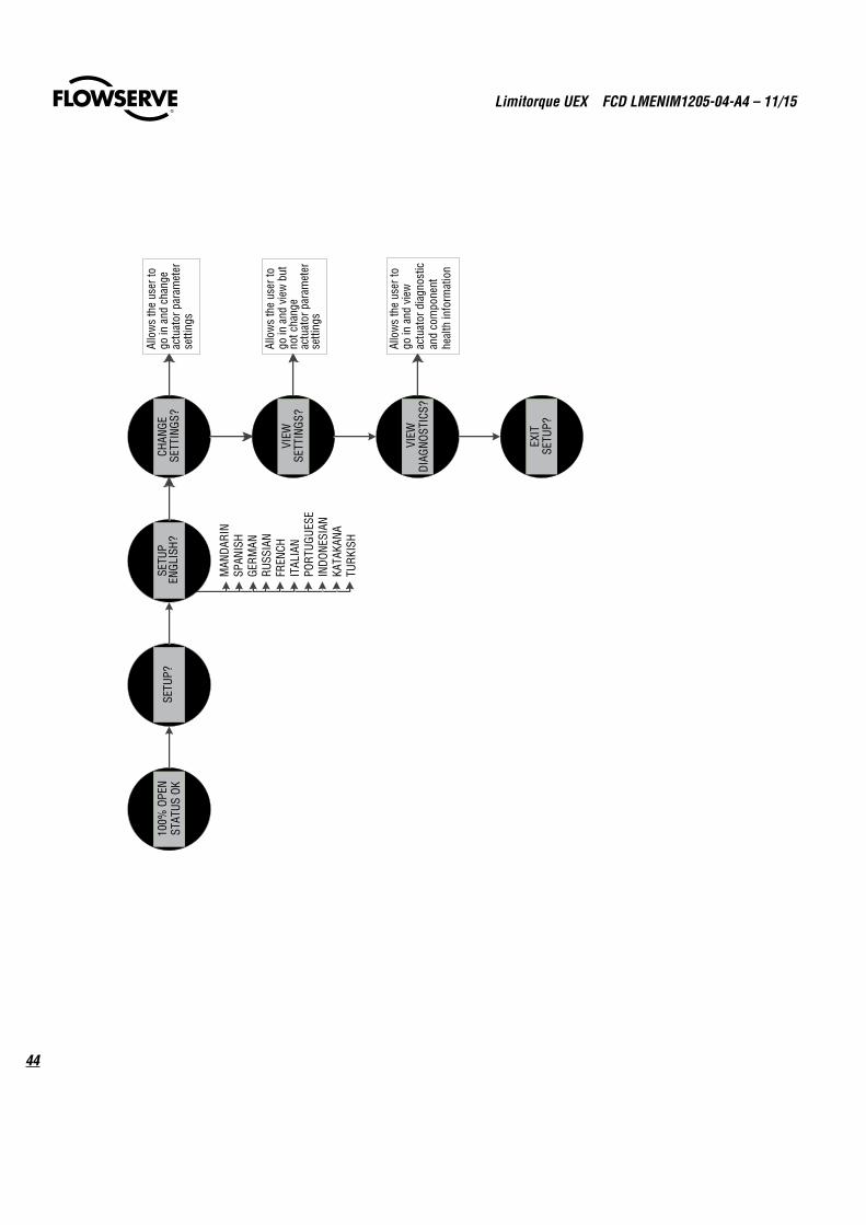
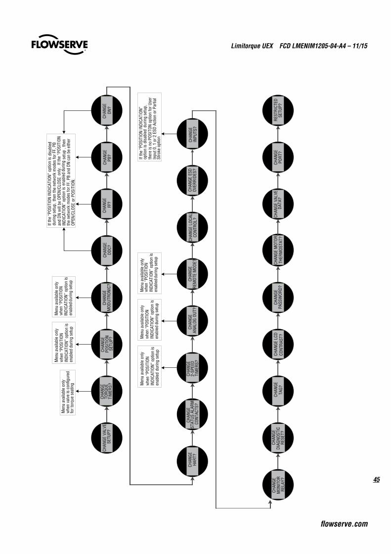
14.3 Setup Menus
43
Limitorque UEX FCD LMENIM1205-04-A4 – 11/15
flowserve.com
SETUPENGLISH?
VOLTAGE460 VAC – OK?
208 VAC230 VAC380 VAC400 VAC415 VAC440 VAC
POSITION INDICATIONENABLED VIEW SETTINGS
VIEW DIAGNOSTICS
INITIALIZE? SET CLOSE POSITION LIMITS?
SET OPEN POSITION LIMITS?
SET PRECISION?
SETUPENGLISH?
CHINESESPANISHGERMANRUSSIANFRENCHITALIANPORTUGUESEMALAYSIANJAPANESETURKISH
CHANGESETTINGS?
ENTER PASSWORD?
PROCEEDS TO THE STANDARD SET
MENUS
ENTER SERIAL NUMBER
INITIALIZE? STATUS OK(CLOSE or OPEN)
PROCEEDS TO THE MENUS AVAILABLE WHEN POSITION INDICATION IS
DISABLED
VALVE SETUP
TORQUE TIMERS
POSITION SETUP
MODUTRONIC
NETWORKS
STATUS & ALARM CONTACTS
2-SPEED TIMERS
ANALOG OUT
REMOTE MODE
LOCAL CONTROL
ESD OVERRIDES
INPUTS
MONITOR RELAY
DIAGNOSTIC RESET
TAG
LCD CONTRAST
PASSWORD
MOTOR THERMOSTAT
VALVE DATA
PORT
RESTRICTED SETUP
USER MUST ENTER SETUP
MODE TO CONFIGURE THE
ACTUATOR
VALVE SETUP
TORQUE TIMERS
NETWORKS
STATUS & ALARM CONTACTS
LOCAL CONTROL
ESD OVERRIDES
INPUTS
MONITOR RELAY
DIAGNOSTIC RESET
TAG
LCD CONTRAST
PASSWORD
MOTOR THERMOSTAT
VALVE DATA
PORT
RESTRICTED SETUP
DISABLED
POSITION INDICATION
ENTER SERIAL NUMBER
CHINESESPANISHGERMANRUSSIANFRENCHITALIANPORTUGUESEMALAYSIANJAPANESETURKISH
Limitorque UEX FCD LMENIM1205-04-A4 – 11/15
44
100%
OPE
NST
ATUS
OK
SETU
P?SE
TUP
ENGL
ISH?
CHAN
GE
SETT
INGS
?
VIEW
SE
TTIN
GS?
VIEW
DI
AGNO
STIC
S?
EXIT
SETU
P?
Allo
ws
the
user
to
go in
and
cha
nge
actu
ator
par
amet
er
setti
ngs
Allo
ws
the
user
to
go in
and
vie
w b
ut
not c
hang
e ac
tuat
or p
aram
eter
se
tting
s
Allo
ws
the
user
to
go in
and
vie
w
actu
ator
dia
gnos
tic
and
com
pone
nt
heal
th in
form
atio
n
MAN
DARI
NSP
ANIS
HGE
RMAN
RUSS
IAN
FREN
CHIT
ALIA
NPO
RTUG
UESE
INDO
NESI
ANKA
TAKA
NATU
RKIS
H
45
Limitorque UEX FCD LMENIM1205-04-A4 – 11/15
flowserve.com
CHAN
GE
STAT
US A
LARM
CO
NTAC
TS?
CHAN
GE
2-SP
EED
TIM
ERS?
CHAN
GEHA
RT?
CHAN
GEAN
ALOG
OUT
?CH
ANGE
RE
MOT
E M
ODE?
CHAN
GE L
OCAL
C
ONTR
OL?
CHAN
GE E
SD O
VERR
IDES
?CH
ANGE
IN
PUTS
?
CHAN
GE
MON
ITOR
RE
LAY?
CHAN
GE
DIAG
NOST
IC
RESE
T?
CHAN
GETA
G?CH
ANGE
LCD
CONT
RAST
?CH
ANGE
PASS
WOR
D?CH
ANGE
MOT
ORTH
ERM
OSTA
T?CH
ANGE
VAL
VEDA
TA?
CHAN
GEPO
RT?
REST
RICT
EDSE
TUP?
CHAN
GE V
ALVE
SETU
P?CH
ANGE
TO
RQUE
TI
MER
S?
CHAN
GE
POSI
TION
SETU
P?CH
ANGE
MOD
UTRO
NIC?
CHAN
GE
DDC?
CHAN
GE
FF?
CHAN
GEPB
?CH
ANGE
DN?
Men
u av
aila
ble
only
w
hen
valv
e is
con
figur
ed
for t
orqu
e se
atin
g
Men
u av
aila
ble
only
w
hen
“POS
ITIO
N IN
DICA
TION
” op
tion
is
enab
led
durin
g se
tup
If th
e “P
OSIT
ION
INDI
CATI
ON”
optio
n is
dis
able
ddu
ring
setu
p, t
hen
the
netw
ork
mod
es fo
r FF,
PB
only
. If
the
“POS
ITIO
Nen
able
ddu
ring
setu
p , t
hen
FF, P
B an
d DN
can
be
eith
er
OPEN
/CLO
SE o
r POS
ITIO
N.
Men
u av
aila
ble
only
w
hen
“POS
ITIO
N IN
DICA
TION
” op
tion
is
enab
ledd
urin
g se
tup
Men
u av
aila
ble
only
w
hen
“POS
ITIO
N IN
DICA
TION
” op
tion
is
enab
led
durin
g se
tup
Men
u av
aila
ble
only
w
hen
“POS
ITIO
N IN
DICA
TION
” op
tion
is
enab
led
durin
g se
tup
If th
e “P
OSIT
ION
INDI
CATI
ON”
optio
n is
disa
bled
durin
g se
tup,
th
ere
is n
o PO
SITO
N op
tion
for U
ser
Inpu
t 0, 1
or 2
ESD
Act
ion
or P
artia
l St
roke
opt
ion
Men
u av
aila
ble
only
w
hen
“POS
ITIO
N IN
DICA
TION
” op
tion
is
enab
ledd
urin
g se
tup
and
DN w
ill b
e OP
EN/C
LOSE
IN
DICA
TION
” op
tion
is
the
netw
ork
mod
es fo
r
Limitorque UEX FCD LMENIM1205-04-A4 – 11/15
46
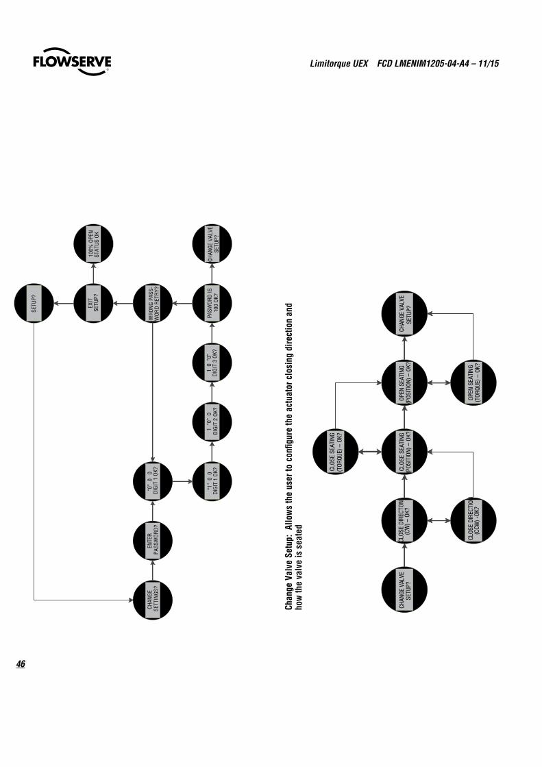
CHAN
GESE
TTIN
GS?
ENTE
RPA
SSW
ORD?
“0”
0
0DI
GIT
1 OK
?
1 “
0” 0
DIGI
T 2
OK?
1 0
“0”
DIGI
T 3
OK?
“1”
0 0
DIGI
T 1
OK?
PASW
ORD
IS10
0 OK
?
WRO
NG
PASS
-W
ORD
RETR
Y?
EXIT
SETU
P?
CHAN
GE V
ALVE
SETU
P?
100%
OPE
NST
ATUS
OK
SETU
P?
CHAN
GE V
ALVE
SETU
P?CL
OSE
DIRE
CTON
(CW
) –OK
?
CLOS
E DI
RECT
ION
(CCW
) -OK
?
CLOS
E SE
ATIN
G(P
OSIT
ION)
–OK
?
CLOS
E SE
ATIN
G(T
ORQU
E) –
OK?
OPEN
SEA
TING
(POS
ITIO
N) –
OK?
OPEN
SEA
TING
(TOR
QUE)
–OK
?
CHAN
GE V
ALVE
SETU
P?
Chan
ge V
alve
Set
up:
Allo
ws
the
user
to c
onfig
ure
the
actu
ator
clo
sing
dire
ctio
n an
d ho
w th
e va
lve
is s
eate
d
47
Limitorque UEX FCD LMENIM1205-04-A4 – 11/15
flowserve.com
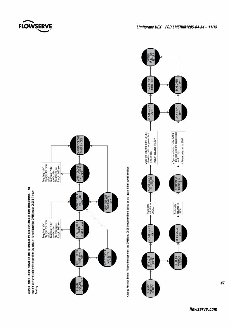
CHAN
GE
TORQ
UETI
MER
S –
OK?
CLOS
E TO
RQUE
TIM
ER (O
N)
–OK
?
CLOS
E TO
RQUE
TIM
ER (O
FF)
–OK
?
CLOS
E TO
RQUE
TI
MER
15 S
ECS
–OK
?
Togg
ling
“NO”
ch
ange
s th
e tim
er
valu
e.
Togg
ling
“YES
” ac
cept
s th
e ch
ange
d va
lue.
Rang
e: 1
-15
secs
OPEN
TOR
QUE
TIM
ER (O
N)–
OK?
OPE
N TO
RQU
E TI
MER
15
SECS
– O
K?
OPEN
TOR
QUE
TIM
ER (O
FF)
–OK
?
CHAN
GE T
ORQU
ETI
MER
S –
OK?
Togg
ling
“NO”
ch
ange
s th
e tim
er
valu
e.
Togg
ling
“YES
” ac
cept
s th
e ch
ange
d va
lue.
Rang
e: 1
-15
secs
Chan
ge T
orqu
e Ti
mer
s: A
llow
s th
e us
er to
con
figur
e th
e ac
tuat
or o
pen
and
clos
e to
rque
tim
ers.
Thi
s m
enu
is o
nly
avai
labl
e to
the
user
whe
n th
e ac
tuat
or is
con
figur
ed fo
r OPE
N an
d/or
CLO
SE T
orqu
e Se
atin
g
CHAN
GE
POS
ITIO
NSE
T CL
OSE
POSI
TION
SET
OPEN
CLOS
E VA
LVE
OK?
OPEN
VAL
VE
OK?
CLOS
E VA
LVE
RETU
RN T
O ST
OP
OPEN
VAL
VE
CLOS
E VA
LVE
OK?
OPEN
VAL
VEOK
?
SAVE
CLO
SELI
MIT
OK?
SAVE
OPE
N LI
MIT
OK?
CHAN
GE
POSI
TION
SE
TUP?
Switc
h th
e ac
tuat
or to
LO
CAL
Switc
h th
e ac
tuat
or to
LO
CAL
Oper
ate
actu
ator
in th
e CL
OSE
dire
ctio
n un
til th
e ge
ared
lim
it sw
itch
trips
Retu
rn a
ctua
tor t
o ST
OP
Oper
ate
actu
ator
in th
e OP
EN
dire
ctio
n un
til th
e ge
ared
lim
it sw
itch
trips
Retu
rn a
ctua
tor t
o ST
OP
Note
: Thi
s m
enu
optio
n is
ava
ilabl
e to
the
user
onl
y w
hen
the
“POS
ITIO
N IN
DICA
TION
” op
tion
has
been
ENA
BLED
dur
ing
the
initi
al a
ctua
tor s
etup
.
Chan
ge P
ositi
on S
etup
: Al
low
s th
e us
er to
set
the
OPEN
and
CLO
SE e
ncod
er li
mits
bas
ed o
n th
e g
eare
d lim
it sw
itch
setti
ngs
SETU
P?LI
MIT
?
POSI
TION
LIM
IT?
RETU
RN T
O ST
OP
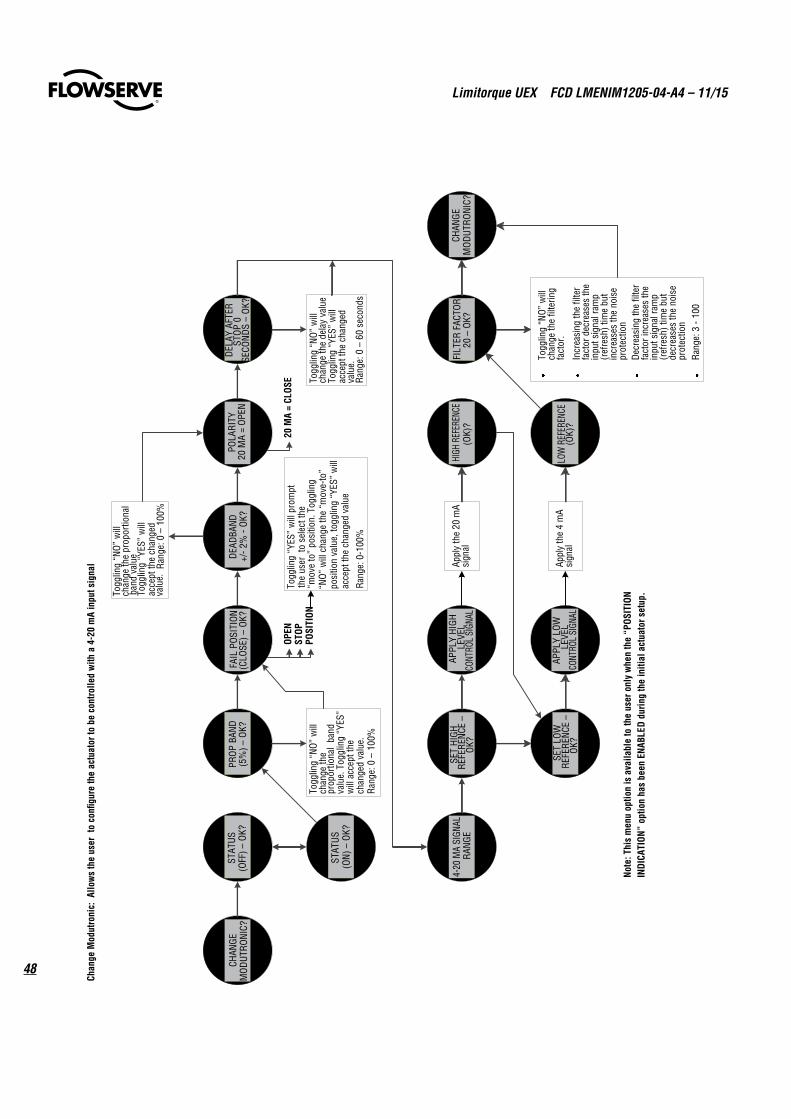
Limitorque UEX FCD LMENIM1205-04-A4 – 11/15
48 CHAN
GEM
ODUT
RONI
C?ST
ATUS
(OFF
) –OK
?
STAT
US(O
N) –
OK?
PROP
BAN
D(5
%) –
OK?
FAIL
POS
ITIO
N(C
LOSE
) –OK
?DE
ADBA
ND+/
-2%
-OK
?PO
LARI
TY20
MA
= OP
ENDE
LAY
AFTE
R ST
OP 0
SECO
NDS
–OK
?
4-20
MA
SIGN
ALRA
NGE
SET
HIGH
REFE
RENC
E –
OK?
APPL
Y HI
GH
LEVE
L CO
NTRO
L SI
GNAL
HIGH
REF
EREN
CE(O
K)?
SET
LOW
REFE
RENC
E –
OK?
APPL
Y LO
W
LEVE
LCO
NTRO
L SI
GNAL
LOW
REF
EREN
CE(O
K)?
FILT
ER F
ACTO
R20
–OK
?
Togg
ling
“NO”
will
ch
ange
the
prop
ortio
nal
band
va
lue.
Tog
glin
g “Y
ES”
will
acc
ept t
he
chan
ged
valu
e.Ra
nge:
0 –
100%
Togg
ling
“NO”
will
ch
ange
the
dela
y va
lue
Togg
ling
“YES
” w
ill
acce
pt th
e ch
ange
d va
lue.
Rang
e: 0
–60
sec
onds
Appl
y th
e 20
mA
sign
al
Appl
y th
e 4
mA
sign
al
CHAN
GEM
ODUT
RONI
C?
Togg
ling
“NO”
will
ch
ange
the
filte
ring
fact
or.
Incr
easi
ng th
e fil
ter
fact
or d
ecre
ases
the
inpu
t sig
nal r
amp
(ref
resh
) tim
e bu
t in
crea
ses
the
nois
e pr
otec
tion
Decr
easi
ng th
e fil
ter
fact
or in
crea
ses
the
inpu
t sig
nal r
amp
(ref
resh
) tim
e bu
t de
crea
ses
the
nois
e pr
otec
tion
Rang
e: 3
-10
0
OPEN
STOP
POSI
TION
Togg
ling
“YES
” w
ill p
rom
pt
the
user
to
sele
ct th
e “m
ove
to”
posi
tion.
Tog
glin
g “N
O” w
ill c
hang
e th
e “m
ove-
to”
posi
tion
valu
e, to
gglin
g “Y
ES”
will
ac
cept
the
chan
ged
valu
e
Rang
e: 0
-100
%
20 M
A =
CLOS
E
Togg
ling
“NO”
will
ch
ange
the
prop
ortio
nal
band
val
ueTo
gglin
g “Y
ES”
will
ac
cept
the
chan
ged
valu
e.Ra
nge:
0 –
100%
Chan
ge M
odut
roni
c: A
llow
s th
e us
er t
o co
nfigu
re th
e ac
tuat
or to
be
cont
rolle
d w
ith a
4-2
0 m
A in
put s
igna
l
Note
: Thi
s m
enu
optio
n is
ava
ilabl
e to
the
user
onl
y w
hen
the
“POS
ITIO
N IN
DICA
TION
” op
tion
has
been
ENA
BLED
dur
ing
the
initi
al a
ctua
tor s
etup
.
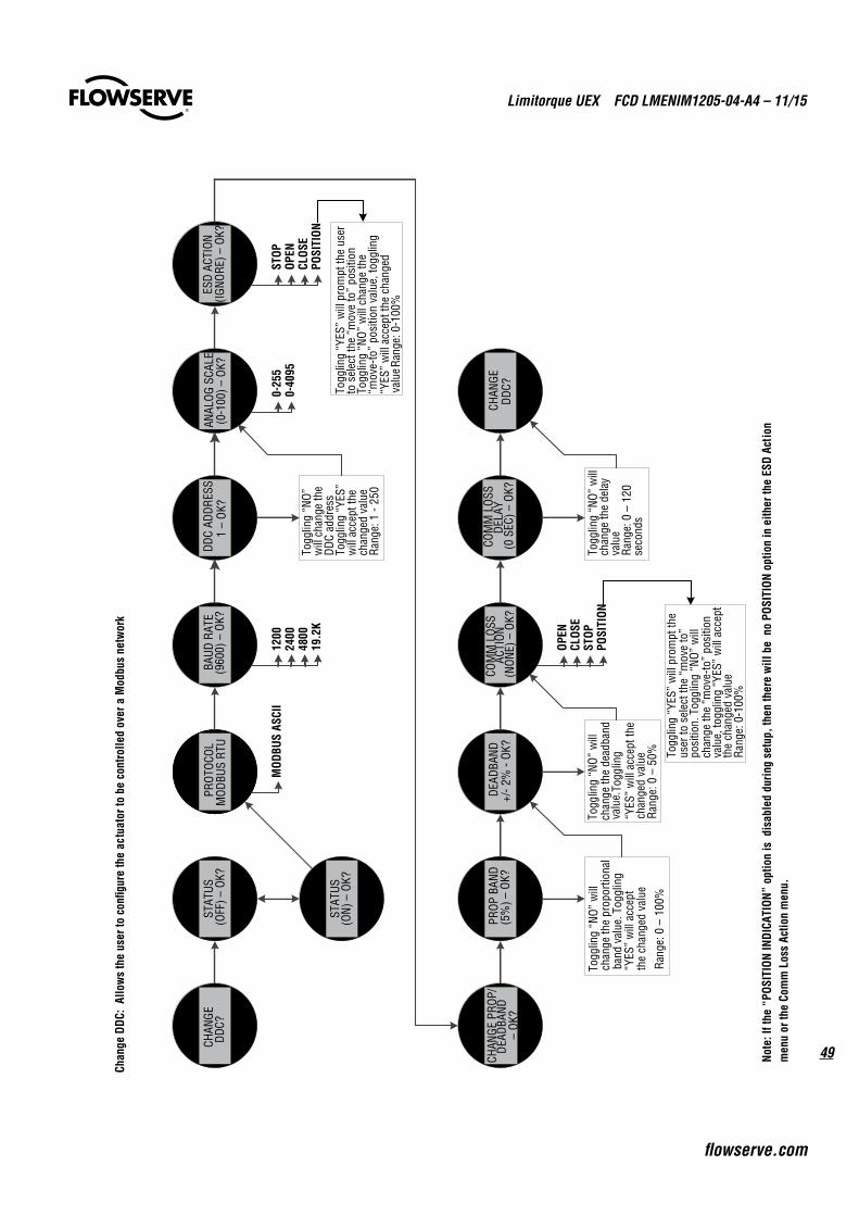
49
Limitorque UEX FCD LMENIM1205-04-A4 – 11/15
flowserve.com
CHAN
GE
DDC?
STAT
US(O
FF) –
OK?
STAT
US(O
N) –
OK?
PROT
OCOL
MOD
BUS
RTU
BAUD
RAT
E(9
600)
–OK
?DD
C AD
DRES
S1
–OK
?AN
ALOG
SCA
LE(0
-100
) –OK
?ES
D AC
TION
(IGNO
RE) –
OK?
CHAN
GE P
ROP/
DEAD
BAND
–
OK?
PROP
BAN
D(5
%) –
OK?
DEAD
BAND
+/-2
% -
OK?
COM
M L
OSS
ACTI
ON(N
ONE)
–OK
?
COM
M L
OSS
DELA
Y(0
SEC
) –OK
?CH
ANGE
DD
C?
Togg
ling
“NO”
w
ill c
hang
e th
eDD
C ad
dres
sTo
gglin
g “Y
ES”
will
acc
ept t
he
chan
ged
valu
eRa
nge:
1 -
250
Togg
ling
“NO”
will
ch
ange
the
prop
ortio
nal
band
val
ue. T
oggl
ing
“YES
” w
ill a
ccep
t th
e ch
ange
d va
lue
Rang
e: 0
–10
0%
Togg
ling
“NO”
will
ch
ange
the
dead
band
va
lue.
Togg
ling
“YES
” w
ill a
ccep
t the
ch
ange
d va
lue
Rang
e: 0
–50
%
Togg
ling
“NO”
will
ch
ange
the
dela
y va
lue
Rang
e: 0
–12
0 se
cond
s
MOD
BUS
ASCI
I12
0024
0048
0019
.2K
0-25
50-
4095
STOP
OPEN
CLOS
EPO
SITI
ON
Togg
ling
“YES
” w
ill p
rom
pt th
e us
er
to s
elec
t the
“m
ove
to”
posi
tion
Togg
ling
“NO”
will
cha
nge
the
“mov
e-to
” po
sitio
n va
lue,
togg
ling
“YES
” w
ill a
ccep
t the
cha
nged
va
lue R
ange
: 0-1
00%
OPEN
CLOS
EST
OPPO
SITI
ON
Togg
ling
“YES
” w
ill p
rom
pt th
eus
er to
sel
ect t
he “
mov
e to
” po
sitio
n. T
oggl
ing
“NO”
will
ch
ange
the
“mov
e-to
” po
sitio
n va
lue,
togg
ling
“YES
” w
ill a
ccep
t th
e ch
ange
d va
lue
Rang
e: 0
-100
%
Chan
ge D
DC:
Allo
ws
the
user
to c
onfig
ure
the
actu
ator
to b
e co
ntro
lled
over
a M
odbu
s ne
twor
k
Note
: If t
he “
POSI
TION
INDI
CATI
ON”
optio
n is
dis
able
d du
ring
setu
p, th
en th
ere
will
be
no
POSI
TION
opt
ion
in e
ither
the
ESD
Acti
onm
enu
or th
e Co
mm
Los
s Ac
tion
men
u.
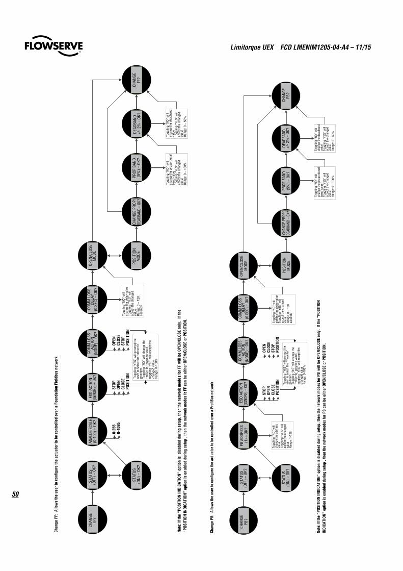
Limitorque UEX FCD LMENIM1205-04-A4 – 11/15
50
CHAN
GE
PB?
STAT
US(O
FF) –
OK?
STAT
US(O
N) –
OK?
PB A
DDRE
SS(1
) –OK
?ES
D AC
TION
(IGNO
RE) –
OK?
COM
M L
OSS
ACTI
ON(N
ONE)
–OK
?
COM
M L
OSS
DELA
Y(0
SEC
) –OK
?OP
EN/C
LOSE
MOD
E
POSI
TION
MOD
ECH
ANGE
PRO
P/DE
ADBA
ND –
OK?
PROP
BAN
D(5
%) –
OK?
DEAD
BAND
+/-2
% -
OK?
CHAN
GEPB
?
Togg
ling
“NO”
will
ch
ange
the
dela
y va
lue
Togg
ling
“YES
” w
ill
acce
pt th
e ch
ange
d va
lue
Rang
e: 0
–12
0 se
cond
s
Togg
ling
“NO”
will
ch
ange
the
prop
ortio
nal
band
val
ueTo
gglin
g “Y
ES”
will
ac
cept
the
chan
ged
valu
eRa
nge:
0 –
100%
Togg
ling
“NO
” w
ill
chan
ge th
e de
adba
nd
valu
eTo
gglin
g “Y
ES”
will
ac
cept
the
chan
ged
valu
eRa
nge:
0 –
50%
STOP
OPEN
CLOS
EPO
SITI
ON Togg
ling
“YES
” w
ill p
rom
pt th
e us
er to
sel
ect t
he “
mov
e to
” po
sitio
nTo
gglin
g “N
O” w
ill c
hang
e th
e “m
ove-
to”
posi
tion
valu
e,
togg
ling
“YES
” w
ill a
ccep
t the
ch
ange
d va
lue
Rang
e: 0
-100
%
OPEN
CLOS
EST
OPPO
SITI
ONTo
gglin
g “N
O” w
ill
chan
ge th
e ad
dres
s va
lue.
To
gglin
g “Y
ES”
will
ac
cept
the
chan
ged
valu
eRa
nge:
1-1
26
Chan
ge P
B: A
llow
s th
e us
er to
con
figur
e th
e ac
tuat
or to
be
cont
rolle
d ov
er a
Pro
fiBus
net
wor
k
Note
: If t
he “
POSI
TION
INDI
CATI
ON”
optio
n is
dis
able
d du
ring
setu
p, th
en th
e ne
twor
k m
odes
for P
B w
ill b
e OP
EN/C
LOSE
onl
y. I
f the
“PO
SITI
ON
INDI
CATI
ON”
optio
n is
ena
bled
dur
ing
setu
p , t
hen
the
netw
ork
mod
es fo
r PB
can
be e
ither
OPE
N/CL
OSE
or P
OSIT
ION.
CHAN
GE
FF?
STAT
US(O
FF) –
OK?
STAT
US(O
N) –
OK?
ANAL
OG S
CALE
(0-1
00) –
OK?
ESD
ACTI
ON(IG
NORE
) –OK
?CO
MM
LOS
S AC
TION
(NON
E) –
OK?
COM
M L
OSS
DELA
Y(0
SEC
) –OK
?OP
EN/C
LOSE
MOD
E
POSI
TION
MOD
ECH
ANGE
PRO
P/DE
ADBA
ND –
OK?
PROP
BAN
D(5
%) –
OK?
DEAD
BAND
+/-2
% -
OK?
CHAN
GE
FF?
Togg
ling
“NO”
will
ch
ange
the
dela
y va
lue
Togg
ling
“YES
” w
ill
acce
pt th
e ch
ange
d va
lue
Rang
e: 0
–12
0 se
cond
s
Togg
ling
“NO
” w
ill
chan
ge th
e pr
opor
tiona
l ba
nd v
alue
Togg
ling
“YES
” w
ill
acce
pt th
e ch
ange
d va
lue
Rang
e: 0
–10
0%
Togg
ling
“NO
” w
ill
chan
ge th
e de
adba
nd
valu
eTo
gglin
g “Y
ES”
will
ac
cept
the
chan
ged
valu
eRa
nge:
0 –
50%
0-25
50-
4095
STOP
OPEN
CLOS
EPO
SITI
ON Togg
ling
“YES
” w
ill p
rom
pt th
e us
er to
sel
ect t
he “
mov
e to
” po
sitio
nTo
gglin
g “N
O” w
ill c
hang
e th
e “m
ove-
to”
posi
tion
valu
e,
togg
ling
“YES
” w
ill a
ccep
t the
ch
ange
d va
lue
Rang
e: 0
-100
%
OPEN
CLOS
EST
OPPO
SITI
ON
Chan
ge F
F: A
llow
s th
e us
er to
con
figur
e th
e ac
tuat
or to
be
cont
rolle
d ov
er a
Fou
ndat
ion
Fiel
dbus
net
wor
k
Note
: If t
he “
POSI
TION
INDI
CATI
ON”
optio
n is
dis
able
d du
ring
setu
p, th
en th
e ne
twor
k m
odes
for F
F w
ill b
e OP
EN/C
LOSE
onl
y. I
f th
e“P
OSIT
ION
INDI
CATI
ON”
optio
n is
en
able
d du
ring
setu
p , t
hen
the
netw
ork
mod
es for
FF
can
be e
ither
OPE
N/CL
OSE
or P
OSIT
ION.
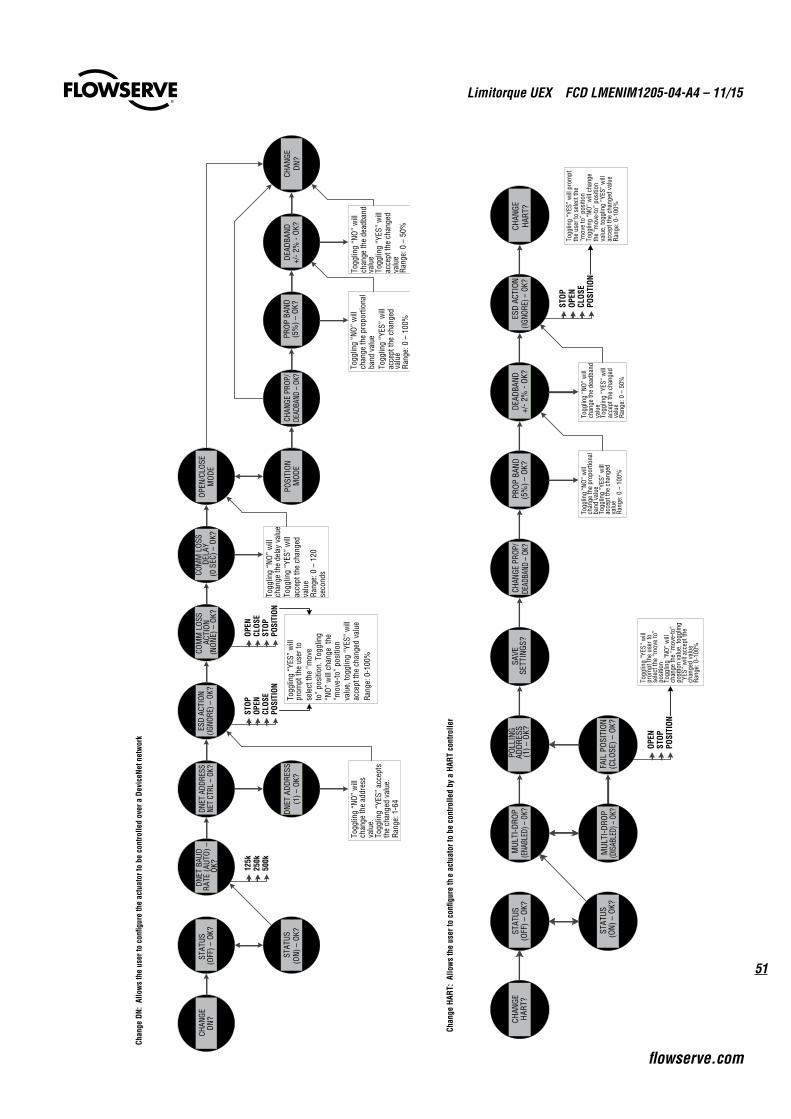
51
Limitorque UEX FCD LMENIM1205-04-A4 – 11/15
flowserve.com
CHAN
GEDN
?ST
ATUS
(OFF
) –OK
?
STAT
US(O
N) –
OK?
DNET
BAU
DRA
TE (A
UTO)
–OK
?DN
ET A
DDRE
SSNE
T CT
RL –
OK?
DNET
ADD
RESS
(1) –
OK?
ESD
ACTI
ON(IG
NORE
) –OK
?CO
MM
LOS
S AC
TION
(NON
E) –
OK?
COM
M L
OSS
DELA
Y(0
SEC
) –OK
?OP
EN/C
LOSE
MOD
E
POSI
TION
MOD
ECH
ANGE
PRO
P/DE
ADBA
ND –
OK?
PROP
BAN
D(5
%) –
OK?
DEAD
BAND
+/-2
% -
OK?
CHAN
GEDN
?
Togg
ling
“NO”
will
ch
ange
the
prop
ortio
nal
band
val
ueTo
gglin
g “Y
ES”
will
ac
cept
the
chan
ged
valu
eRa
nge:
0 –
100%
Togg
ling
“NO”
will
ch
ange
the
dead
band
va
lue
Togg
ling
“YES
” w
ill
acce
pt th
e ch
ange
d va
lue
Rang
e: 0
–50
%
Togg
ling
“NO
” w
ill
chan
ge th
e de
lay
valu
eTo
gglin
g “Y
ES”
will
ac
cept
the
chan
ged
valu
eRa
nge:
0 –
120
seco
nds
125k
250k
500k
Togg
ling
“NO”
will
ch
ange
the
addr
ess
valu
e.
Togg
ling
“YES
” ac
cept
s th
e ch
ange
d va
lue.
Rang
e: 1
-64
STOP
OPEN
CLOS
EPO
SITI
ON
Togg
ling
“YES
” w
ill
prom
pt th
e us
er to
se
lect
the
“mov
e to
” po
sitio
n. T
oggl
ing
“NO
” w
ill c
hang
e th
e“m
ove-
to”
posi
tion
acce
pt th
e ch
ange
d va
lue
Rang
e: 0
-100
%
OPEN
CLOS
EST
OPPO
SITI
ON
Chan
ge D
N: A
llow
s th
e us
er to
con
figur
e th
e ac
tuat
or to
be
cont
rolle
d ov
er a
Dev
iceN
et n
etw
ork
Note
: If t
he “
POSI
TION
INDI
CATI
ON”
optio
n is
dis
able
d du
ring
setu
p, th
en th
e ne
twor
k m
odes
for D
N w
ill b
e OP
EN/C
LOSE
onl
y. I
f th
e “P
OSIT
ION
INDI
CATI
ON”
optio
n is
ena
bled
dur
ing
setu
p , t
hen
the
netw
ork
mod
es fo
r DN
can
be e
ither
OPE
N/CL
OSE
or P
OSIT
ION.
valu
e, to
gglin
g “Y
ES”
will
Togg
ling
“YES
” w
ill
prom
pt th
e us
er to
se
lect
the
“mov
e to
” po
sitio
nTo
gglin
g “N
O” w
ill
chan
ge th
e “m
ove-
to”
posi
tion
valu
e, to
gglin
g “Y
ES”
will
acc
ept t
he
chan
ged
valu
eRa
nge:
0-1
00%
CHAN
GEHA
RT?
STAT
US(O
FF) –
OK?
STAT
US(O
N) –
OK?
MUL
TI-D
ROP
(ENA
BLED
) –OK
?
MUL
TI-D
ROP
(DIS
ABLE
D) –
OK?
FAIL
POS
ITIO
N(C
LOSE
) –OK
?
POLL
ING
ADDR
ESS
(1) –
OK?
SAVE
SETT
INGS
?CH
ANGE
PRO
P/DE
ADBA
ND –
OK?
PROP
BAN
D(5
%) –
OK?
DEAD
BAND
+/-2
% -
OK?
Togg
ling
“NO
” w
ill
chan
ge th
e pr
opor
tiona
l ba
nd v
alue
Togg
ling
“YES
” w
ill
acce
pt th
e ch
ange
d va
lue
Rang
e: 0
–10
0%
Togg
ling
“NO”
will
ch
ange
the
dead
band
va
lue
Togg
ling
“YES
” w
ill
acce
pt th
e ch
ange
d va
lue
Ran
ge: 0
–50
%
ESD
ACTI
ON(IG
NORE
) –OK
?CH
ANGE
HART
?
OPEN
POSI
TION
STOP
STOP
OPEN
CLOS
EPO
SITI
ON
Togg
ling
“YES
” w
ill p
rom
pt
the
user
to s
elec
t the
“m
ove
to”
posi
tion
Togg
ling
“NO”
will
cha
nge
the
“mov
e-to
” po
sitio
n va
lue,
togg
ling
“YES
” w
ill
acce
pt th
e ch
ange
d va
lue
Rang
e: 0
-100
%
Chan
ge H
ART:
Allo
ws
the
user
to c
onfig
ure
the
actu
ator
to b
e co
ntro
lled
by a
HAR
T co
ntro
ller
Note
: Thi
s m
enu
optio
n is
ava
ilabl
e to
the
user
onl
y w
hen
the
“POS
ITIO
N IN
DICA
TION
” op
tion
has
been
ENA
BLED
dur
ing
the
initi
al a
ctua
tor s
etup
.
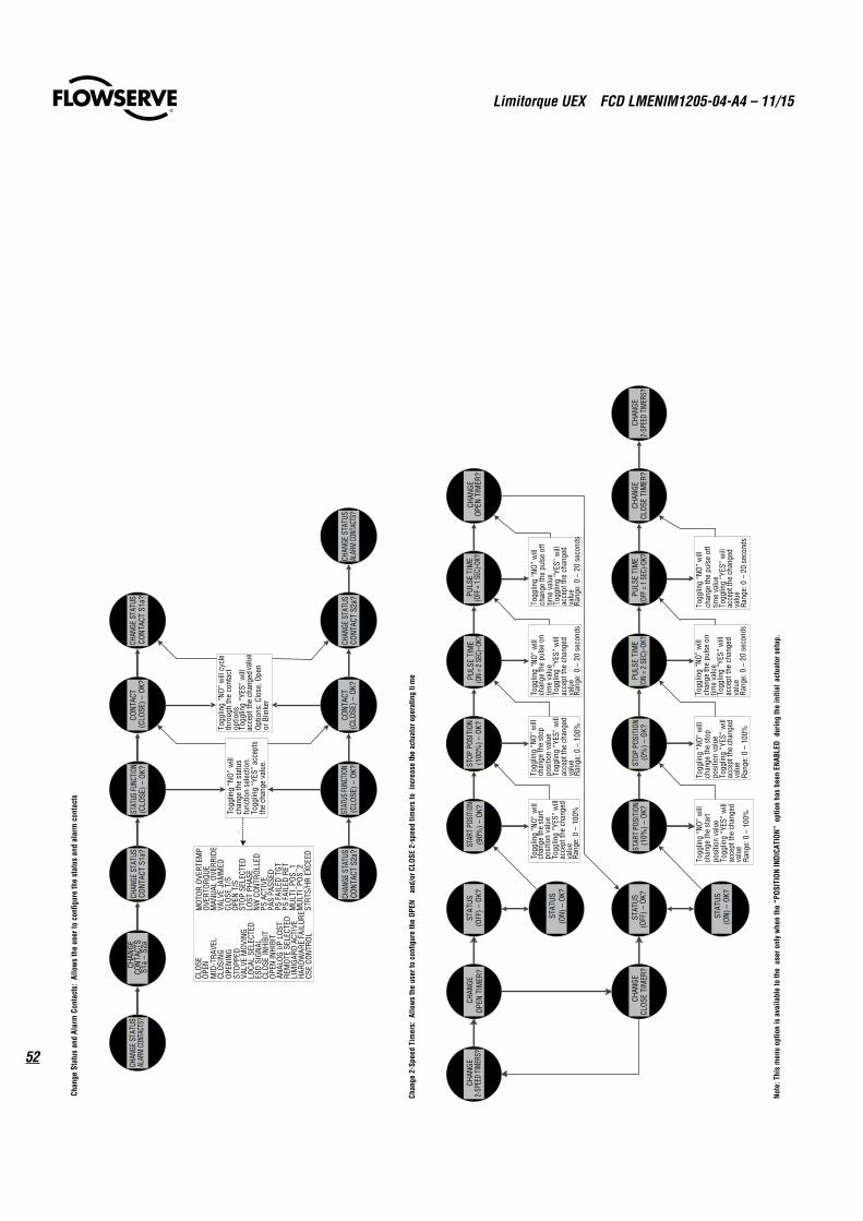
Limitorque UEX FCD LMENIM1205-04-A4 – 11/15
52
CHAN
GE S
TATU
SAL
ARM
CONT
ACTS
?CH
ANGE
CO
NTAC
TSS1
a –
S2a
CHAN
GE S
TATU
SCO
NTA
CT S
1a?
STAT
US FU
NCTIO
N(C
LOSE
) –O
K?
STAT
US FU
NCTI
ON(C
LOSE
) –O
K?CO
NTAC
T(C
LOSE
) –OK
?
CONT
ACT
(CLO
SE) –
OK?
CHAN
GE S
TATU
SCO
NTAC
T S1
a?
CHAN
GE S
TATU
SCO
NTAC
T S2
a?CH
ANGE
STA
TUS
ALAR
M CO
NTAC
TS?
CHAN
GE S
TATU
SCO
NTA
CT S
2a?
Togg
ling
“NO”
will
cyc
le
thro
ugh
the
cont
act
optio
nsTo
gglin
g “Y
ES”
will
ac
cept
the
chan
ged v
alue
Optio
ns: C
lose
, Ope
n or
Blin
ker
MOT
OR O
VERT
EMP
OVER
TORQ
UEM
ANUA
L OV
ERRI
DEVA
LVE
JAM
MED
CLOS
E T/
SOP
EN T
/SST
OP S
ELEC
TED
LOST
PHA
SENW
CON
TROL
LED
PS A
CTIV
EPA
S PA
SSED
PS F
AILE
D TG
TPS
FAI
LED
RET
MUL
TI_P
OS_1
MUL
TI_P
OS_2
STRT
S/HR
EXC
EED
CLO
SEOP
ENM
ID-T
RAVE
LCL
OSIN
GOP
ENIN
GST
OPPE
DVA
LVE
MOV
ING
LOCA
L SE
LECT
EDES
D SI
GNAL
CLOS
E IN
HIBI
TOP
EN IN
HIBI
TAN
ALOG
I/P
LOST
REM
OTE
SELE
CTED
LIM
IGAR
D AC
TIVE
HARD
WAR
E FA
ILUR
ECS
E CO
NTRO
L
Togg
ling
“NO”
will
ch
ange
the
stat
us
func
tion
sele
ctio
n.
Togg
ling
“YES
” ac
cept
s th
e ch
ange
val
ue.
Chan
ge S
tatu
s an
d Al
arm
Con
tact
s: A
llow
s th
e us
er to
con
figur
e th
e st
atus
and
ala
rm c
onta
cts
CHAN
GE2-
SPEE
D TI
MER
S?CH
ANGE
OPEN
TIM
ER?
CHAN
GE
CLOS
E TI
MER
?
STAT
US(O
FF) –
OK?
STAT
US(O
N) –
OK?
STAR
T PO
SITI
ON(9
0%) –
OK?
STAT
US(O
FF) –
OK?
STAT
US(O
N) –
OK?
STAR
T PO
SITI
ON(1
0%) –
OK?
STOP
POS
ITIO
N(1
00%
) –OK
?PU
LSE
TIM
E(O
N =
2 SE
C)–O
K?PU
LSE
TIM
E(O
FF =
1 SEC
)-OK?
CHAN
GEOP
EN T
IMER
?
STOP
POS
ITIO
N(0
%) –
OK?
PULS
E TI
ME
(ON
= 2
SEC)
–OK?
CHAN
GE
CLOS
E TI
MER
?CH
ANGE
2-SP
EED
TIM
ERS?
Togg
ling
“NO”
will
ch
ange
the
star
t po
sitio
n va
lue
Togg
ling
“YES
” w
ill
acce
pt th
e ch
ange
d va
lue
Rang
e: 0
–10
0%
Togg
ling
“NO”
will
ch
ange
the
stop
po
sitio
n va
lue
Togg
ling
“YES
” w
ill
acce
pt th
e ch
ange
d va
lue
Rang
e: 0
–10
0%
Togg
ling
“NO”
will
ch
ange
the
puls
e on
tim
e va
lue
Togg
ling
“YES
” w
ill
acce
pt th
e ch
ange
d va
lue
Rang
e: 0
–20
sec
onds
PULS
E TI
ME
(OFF
= 1
SEC
)-OK?
Togg
ling
“NO”
will
ch
ange
the
puls
e of
f tim
e va
lue
Togg
ling
“YES
” w
ill
acce
pt th
e ch
ange
d va
lue
Rang
e: 0
–20
sec
onds
Togg
ling
“NO”
will
ch
ange
the
star
t po
sitio
n va
lue
Togg
ling
“YES
” w
ill
acce
pt th
e ch
ange
d va
lue
Rang
e: 0
–10
0%
Togg
ling
“NO”
will
ch
ange
the
stop
po
sitio
n va
lue
Togg
ling
“YES
” w
ill
acce
pt th
e ch
ange
d va
lue
Rang
e: 0
–10
0%
Togg
ling
“NO”
will
ch
ange
the
puls
e on
tim
e va
lue
Togg
ling
“YES
” w
ill
acce
pt th
e ch
ange
d va
lue
Rang
e: 0
–20
sec
onds
Togg
ling
“NO”
will
ch
ange
the
puls
e of
f tim
e va
lue
Togg
ling
“YES
” w
ill
acce
pt th
e ch
ange
d va
lue
Rang
e: 0
–20
sec
onds
Chan
ge 2
-Spe
ed T
imer
s: A
llow
s th
e us
er to
con
figur
e th
e OP
EN
and/
or C
LOSE
2-s
peed
tim
ers
to i
ncre
ase
the
actu
ator
ope
ratin
g ti
me
Note
: Thi
s m
enu
optio
n is
ava
ilabl
e to
the
user
onl
y w
hen
the
“POS
ITIO
N IN
DICA
TION
” op
tion
has
been
ENA
BLED
dur
ing
the
initi
al a
ctua
tor s
etup
.
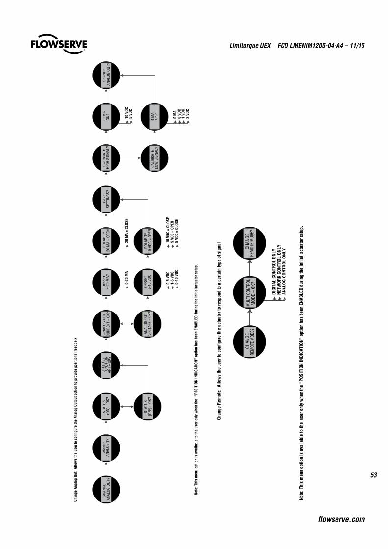
53
Limitorque UEX FCD LMENIM1205-04-A4 – 11/15
flowserve.com
CHAN
GEAN
ALOG
OUT
?CH
ANGE
AN
ALOG
1?
STAT
US(O
N) –
OK?
STAT
US(O
FF) –
OK?
STAT
US
FUNC
TION
APT
–OK
?AN
ALOG
OUT
CURR
ENT
–OK
?
ANAL
OG O
UTVO
LTAG
E –
OK?
OFFS
ET4-
20 M
A?
OFFS
ET2-
10 V
DC
POLA
RITY
20 M
A =
OPEN
POLA
RITY
10 V
DC =
OPE
N
SAVE
SETT
INGS
?CA
LIBR
ATE
HIGH
SIG
NAL?
CALI
BRAT
ELO
W S
IGNA
L?
20 M
AOK
?
4 M
AOK
?
CHAN
GEAN
ALOG
OUT
?
0-20
MA
20 M
A =
CLOS
E
0-5
VDC
1-5
VDC
0-10
VDC
10 V
DC =
CLO
SE5
VDC
= OP
EN5
VDC
= CL
OSE
10 V
DC5
VDC
0 M
A0
VDC
1 VD
C2
VDC
Note
: Thi
s m
enu
optio
n is
ava
ilabl
e to
the
user
onl
y w
hen
the
“POS
ITIO
N IN
DICA
TION
” op
tion
has
been
ENA
BLED
dur
ing
the
initi
al a
ctua
tor s
etup
.
Chan
ge A
nalo
g Ou
t: A
llow
s th
e us
er to
con
figur
e th
e An
alog
Out
put o
ptio
n to
pro
vide
pos
ition
al fe
edba
ck
CHAN
GE
REM
OTE
MOD
E?M
ULTI
CON
TROL
MOD
E –
OK?
CHAN
GE
REM
OTE
MOD
E?
DIGI
TAL
CONT
ROL
ONLY
NETW
ORK
CONT
ROL
ONLY
ANAL
OG C
ONTR
OL O
NLY
Chan
ge R
emot
e: A
llow
s th
e us
er to
con
figur
e th
e ac
tuat
or to
resp
ond
to a
cer
tain
type
of s
igna
l
Note
: Thi
s m
enu
optio
n is
ava
ilabl
e to
the
user
onl
y w
hen
the
“POS
ITIO
N IN
DICA
TION
” op
tion
has
been
ENA
BLED
dur
ing
the
initi
al a
ctua
tor s
etup
.
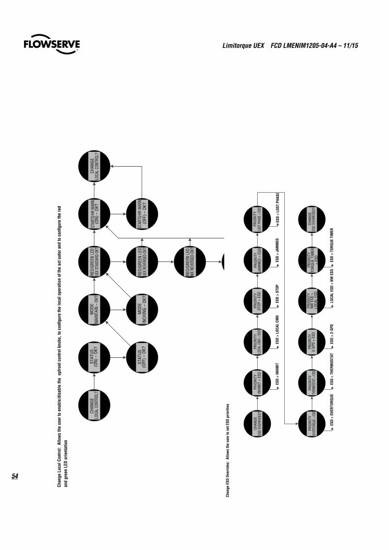
Limitorque UEX FCD LMENIM1205-04-A4 – 11/15
54
CHAN
GE
LOCA
L CON
TROL
?ST
ATUS
(ON)
–OK
?
STAT
US(O
FF) –
OK?
MOD
EM
AINT
AIN
–OK
?
MOD
EIN
CHIN
G –
OK?
RED/
GREE
N LE
DUE
X STA
NDAR
D-OK
?ST
ARTS
/HR
WAR
N(O
N) –
OK?
RED/
GREE
N LE
DUE
X RE
VERS
ED-O
K?ST
ARTS
/HR
WAR
N(O
FF) –
OK?
CHAN
GE
LOCA
L CON
TROL
?
RED/
GREE
N LE
DM
X RE
VERS
ED-O
K?
RED/
GREE
N LE
DMX
STA
NDAR
D-OK
?
Chan
ge L
ocal
Con
trol:
Allo
ws
the
user
to e
nabl
e/di
sabl
e th
e up
front
con
trol k
nobs
, to
confi
gure
the
loca
l ope
ratio
n of
the
actu
ator
and
to c
onfig
ure
the
red
and
gree
n LE
D or
ient
atio
n
CHAN
GEES
D OV
ERRI
DES?
PRIO
RITY
INHI
BIT
> ES
DPR
IORI
TYLO
CAL
CMD
> ES
DPR
IORI
TYST
OP >
ESD
PRIO
RITY
JAM
MED
> E
SDPR
IORI
TYLO
ST P
HASE
> ES
D
PRIO
RITY
OVER
TORQ
UE >
ESD
PRIO
RITY
THER
MOST
AT >
ESD
PRIO
RITY
2-SP
D +
ESD
PRIO
RITY
NW E
SD >
LO
CAL
ESD
PRIO
RITY
TORQ
UE T
IMER
> E
SD
CHAN
GEES
D OV
ERRI
DES?
ESD
> IN
HIBI
TES
D >
LOCA
L CM
DES
D >
STOP
ESD
> JA
MM
EDES
D >
LOST
PHA
SE
ESD
> OV
ERTO
RQUE
ESD
> TH
ERM
OSTA
TES
D >
2-SP
DLO
CAL
ESD
> NW
ESD
ESD
> TO
RQUE
TIM
ER
Chan
ge E
SD O
verr
ides
: Al
low
s th
e us
er to
set
ESD
prio
ritie
s
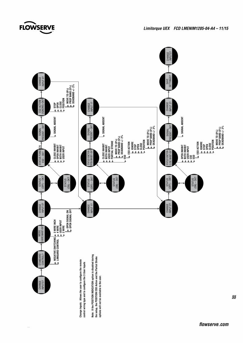
55
Limitorque UEX FCD LMENIM1205-04-A4 – 11/15
flowserve.com
CHAN
GE
INPU
TS?
STAN
DARD
CONT
ROL?
MOD
E3 W
IRE M
AINT
-OK?
CHAN
GEIN
PUT
0?
CHAN
GE
INPU
T 1?
CHAN
GEIN
PUT
2?
STAT
US(O
FF) –
OK?
STAT
US(O
N) –
OK?
STAT
US F
UNCT
ION
ESD
–OK
?SI
GNAL
PRES
ENT
–OK
?ES
D AC
TION
(IGNO
RE)-
OK?
CHAN
GEIN
PUT
0?
STAT
US(O
FF) –
OK?
STAT
US(O
N) –
OK?
STAT
US FU
NCTIO
NOP
EN IN
HIBI
T–OK
?SI
GNAL
PRES
ENT
–OK
?CH
ANGE
IN
PUT
1?
STAT
US(O
FF) –
OK?
STAT
US(O
N) –
OK?
STAT
US FU
NCTIO
NCL
OSE I
NHIBI
T-OK?
SIGN
ALPR
ESEN
T –
OK?
CHAN
GEIN
PUT
2?SA
VESE
TTIN
GS?
CHAN
GE
INPU
TS?
NEGA
TIVE
SW
ITCH
ING
LIM
IGAR
D CO
NTRO
L3
WIR
E IN
CH4
WIR
EUS
ER IN
PUT
2 W
IRE
OPEN
SIG
NAL
ONOP
EN S
IGNA
L OF
F
CLOS
E IN
HIBI
TOP
EN IN
HIBI
TBO
TH IN
HIBI
TUS
ER IN
PUT
SIGN
AL A
BSEN
TST
OPOP
ENCL
OSE
POSI
TION
MOV
E TO
(0%
)PR
OP B
AND
(5%
)DE
ADBA
ND +
/-2%
IGNO
REST
OPOP
ENCL
OSE
POSI
TION
SIGN
AL A
BSEN
T
SIGN
AL A
BSEN
T
CLOS
E IN
HIBI
TBO
TH IN
HIBI
TUS
ER IN
PUT
PART
IAL
STRO
KE
MOV
E TO
(0%
)PR
OP B
AND
(5%
)DE
ADBA
ND +
/-2%
ESD
ESD
ACTI
ON MOV
E TO
(0%
)PR
OP B
AND
(5%
)DE
ADBA
ND +
/-2%
OPEN
INHI
BIT
BOTH
INHI
BIT
USER
INPU
TCS
E
ESD
ACTI
ONIG
NORE
STOP
OPEN
CLOS
EPO
SITI
ON
MOV
E TO
(0%
)PR
OP B
AND
(5%
)DE
ADBA
ND +
/-2%
ESD
Chan
ge In
puts
: Al
low
s th
e us
er to
con
figur
e th
e re
mot
e co
ntro
l wiri
ng ty
pe a
nd to
con
figur
e th
e 3
User
Inpu
ts
Note
: If
the
POSI
TION
INDI
CATI
ON o
ptio
n is
dis
able
d du
ring
the
setu
p, th
e PO
SITI
ON E
SD A
ctio
n an
d th
e Pa
rtial
Stro
ke
optio
ns w
ill n
ot b
e av
aila
ble
to th
e us
er.
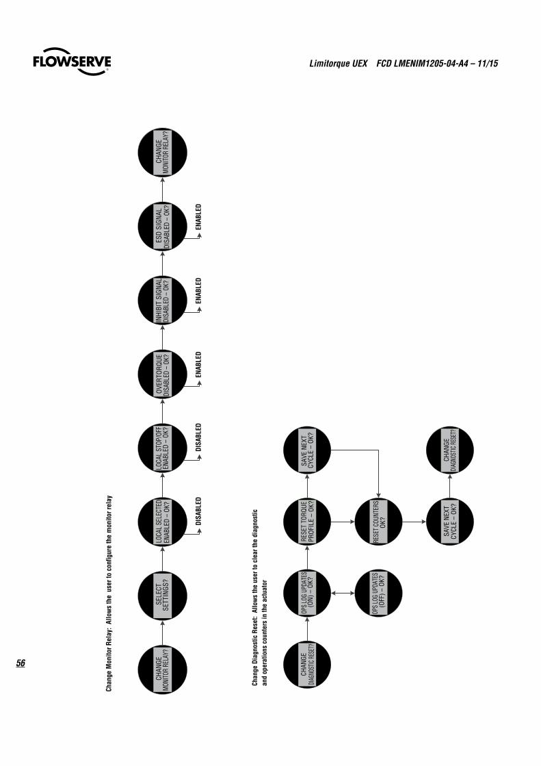
Limitorque UEX FCD LMENIM1205-04-A4 – 11/15
56
CHAN
GE
MON
ITOR
REL
AY?
SELE
CTSE
TTIN
GS?
LOCA
L SE
LECT
EDEN
ABLE
D –
OK?
LOCA
L ST
OP/O
FFEN
ABLE
D –
OK?
OVER
TORQ
UEDI
SABL
ED –
OK?
INHI
BIT
SIGN
ALDI
SABL
ED –
OK?
ESD
SIGN
ALDI
SABL
ED –
OK?
CHAN
GE
MON
ITOR
REL
AY?
DISA
BLED
DISA
BLED
ENAB
LED
ENAB
LED
ENAB
LED
Chan
ge M
onito
r Rel
ay:
Allo
ws
the
user
to c
onfig
ure
the
mon
itor r
elay
CHAN
GE
DIAG
NOST
IC RE
SET?
OPS
LOG
UPDA
TES
(ON
) –O
K?
OPS
LOG
UPDA
TES
(OFF
) –OK
?
RESE
T TO
RQUE
PROF
ILE
–OK
?SA
VE N
EXT
CYCL
E –
OK?
RESE
T CO
UNTE
RSOK
?
SAVE
NEX
TCY
CLE
–OK
?CH
ANG
E DI
AGNO
STIC
RESE
T?
Chan
ge D
iagn
ostic
Res
et:
Allo
ws
the
user
to c
lear
the
diag
nost
ic
and
oper
atio
ns c
ount
ers
in th
e ac
tuat
or
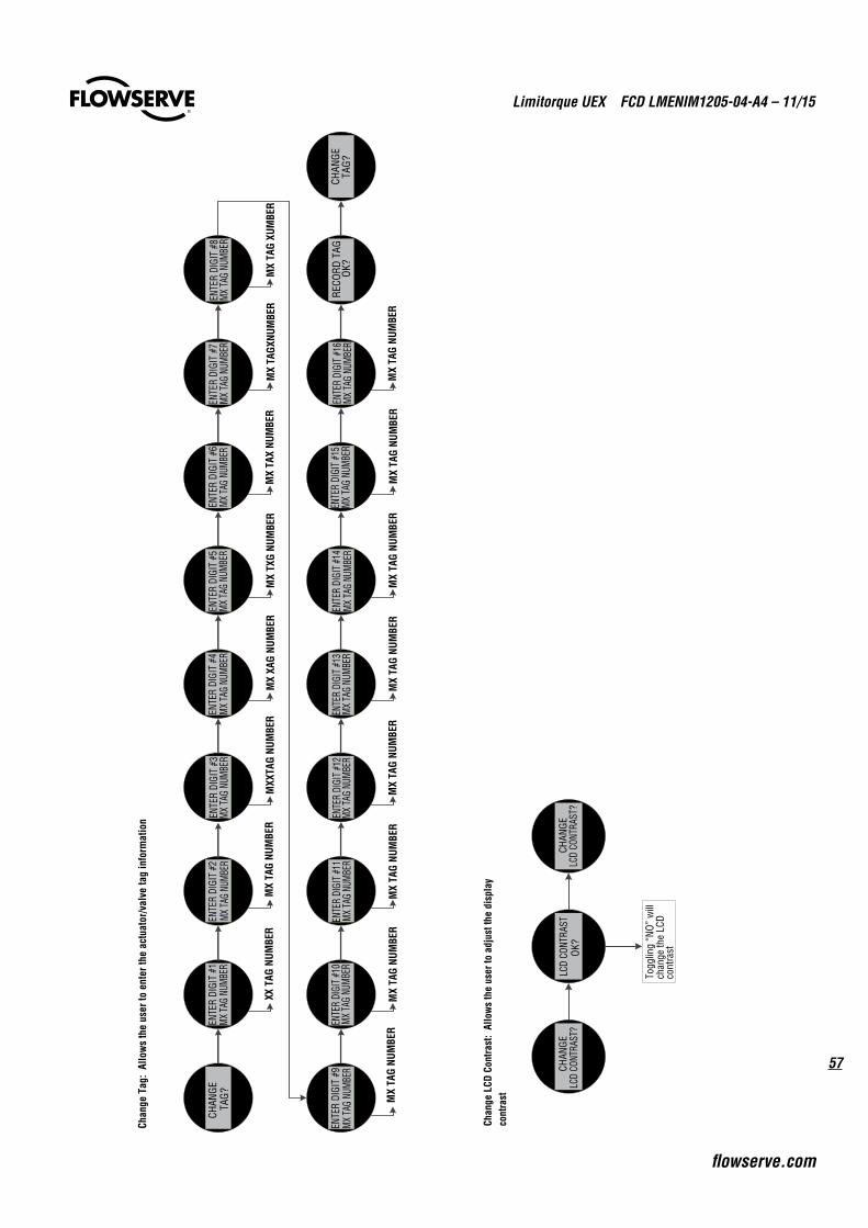
57
Limitorque UEX FCD LMENIM1205-04-A4 – 11/15
flowserve.com
CHAN
GETA
G?EN
TER
DIGI
T #1
MX
TAG
NUM
BER
ENTE
R DI
GIT
#2MX
TAG
NUMB
EREN
TER
DIGI
T #3
MX
TAG
NUM
BER
ENTE
R DI
GIT
#4M
X TA
G NU
MBE
REN
TER
DIGI
T #5
MX
TAG
NUM
BER
ENTE
R DI
GIT
#6MX
TAG
NUMB
EREN
TER
DIGI
T #7
MX
TAG
NUM
BER
ENTE
R DI
GIT
#8M
X TA
G NU
MBE
R
ENTE
R DI
GIT
#9M
X TA
G NU
MBER
ENTE
R DI
GIT
#10
MX
TAG
NUM
BER
ENTE
R DI
GIT
#11
MX
TAG
NUM
BER
ENTE
R DI
GIT #
12M
X TA
G NU
MBE
REN
TER
DIGI
T #1
3M
X TA
G NU
MBE
REN
TER
DIGI
T #1
4M
X TA
G NU
MBE
REN
TER
DIGI
T #1
5M
X TA
G NU
MBE
REN
TER
DIGI
T #1
6M
X TA
G NU
MBE
RRE
CORD
TAG
OK?
CHAN
GETA
G?
XX T
AG N
UMBE
RM
X TA
G NU
MBE
RM
XXTA
G NU
MBE
RM
X XA
G NU
MBE
RM
X TX
G NU
MBE
RM
X TA
X NU
MBE
RM
X TA
GXNU
MBE
RM
X TA
G XU
MBE
R
MX
TAG
NUM
BER
MX
TAG
NUM
BER
MX
TAG
NUM
BER
MX
TAG
NUM
BER
MX
TAG
NUM
BER
MX
TAG
NUM
BER
MX
TAG
NUM
BER
MX
TAG
NUM
BER
Chan
ge T
ag:
Allo
ws
the
user
to e
nter
the
actu
ator
/val
ve ta
g in
form
atio
n
CHAN
GELC
D CO
NTRA
ST?
LCD
CONT
RAST
OK?
CHAN
GELC
D CO
NTRA
ST?
Togg
ling
“NO”
will
ch
ange
the
LCD
cont
rast
Chan
ge L
CD C
ontra
st:
Allo
ws
the
user
to a
djus
t the
dis
play
co
ntra
st
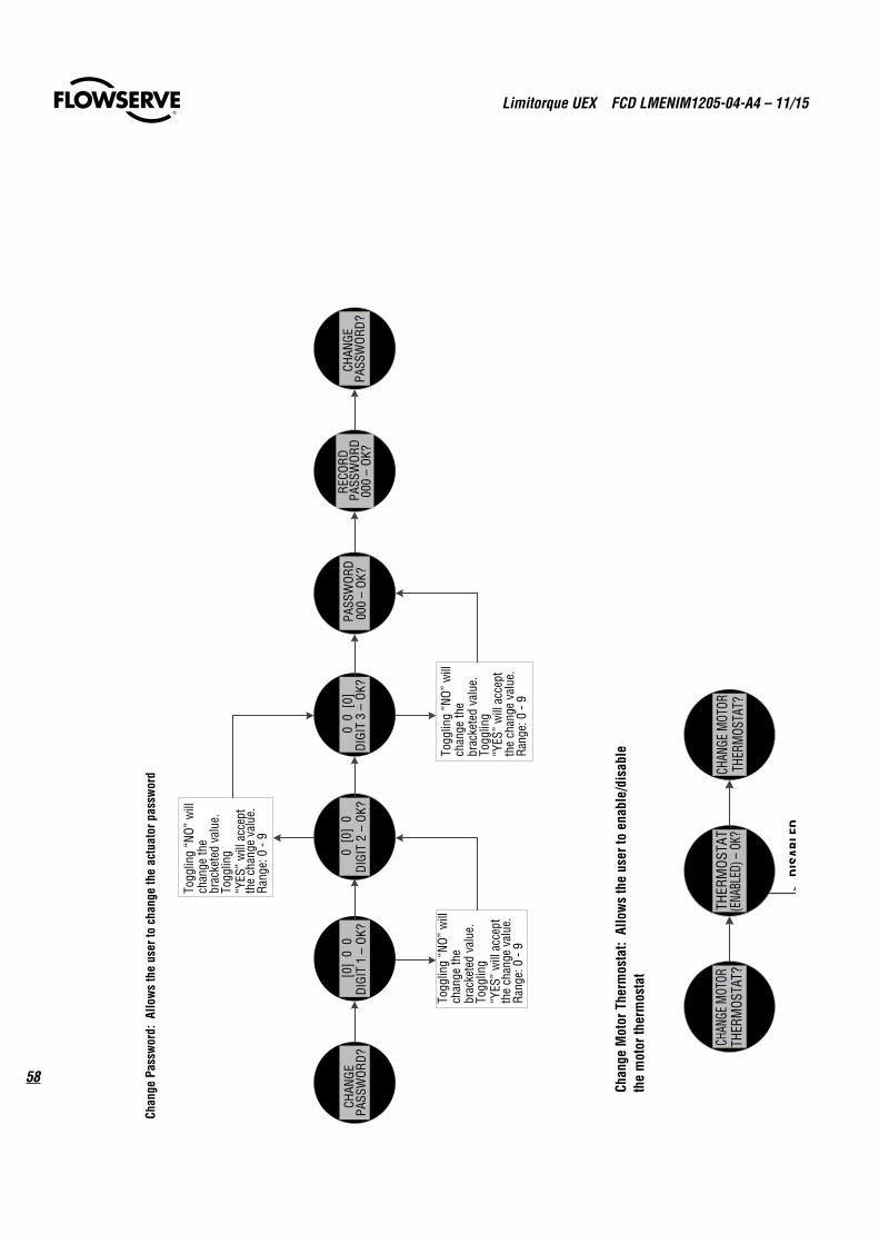
Limitorque UEX FCD LMENIM1205-04-A4 – 11/15
58
CHAN
GEPA
SSW
ORD?
[0]
0 0
DIGI
T 1
–OK
?0
[0]
0DI
GIT
2 –
OK?
0 0
[0]
DIGI
T 3
–OK
?PA
SSW
ORD
000
–OK
?RE
COR
D PA
SSW
ORD
000
–OK
?CH
ANGE
PASS
WOR
D?
Togg
ling
“NO”
will
ch
ange
the
brac
kete
d va
lue.
Togg
ling
“YES
” w
ill a
ccep
t th
e ch
ange
val
ue.
Rang
e: 0
-9
Togg
ling
“NO”
will
ch
ange
the
brac
kete
d va
lue.
Togg
ling
“YES
” w
ill a
ccep
t th
e ch
ange
val
ue.
Rang
e: 0
-9
Togg
ling
“NO”
will
ch
ange
the
brac
kete
d va
lue.
Togg
ling
“YES
” w
ill a
ccep
t th
e ch
ange
val
ue.
Rang
e: 0
-9
Chan
ge P
assw
ord:
Allo
ws
the
user
to c
hang
e th
e ac
tuat
or p
assw
ord
CHAN
GE M
OTOR
THER
MOS
TAT?
THER
MOS
TAT
(ENA
BLED
) –OK
?CH
ANGE
MOT
ORTH
ERM
OSTA
T?
DISA
BLED
Chan
ge M
otor
The
rmos
tat:
Allo
ws
the
user
to e
nabl
e/di
sabl
e th
e m
otor
ther
mos
tat
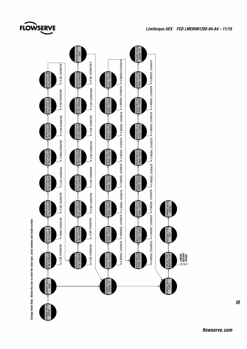
59
Limitorque UEX FCD LMENIM1205-04-A4 – 11/15
flowserve.com
CHAN
GE V
ALVE
DATA
?EN
TER
DIGI
T #1
V SN
123
4567
89EN
TER
DIGI
T #2
V SN
123
4567
89EN
TER
DIGI
T #3
V SN
123
4567
89EN
TER
DIGI
T #4
V SN
123
4567
89EN
TER
DIGI
T #5
V SN
123
4567
89EN
TER
DIGI
T #6
V SN
123
4567
89EN
TER
DIGI
T #7
V SN
123
4567
89EN
TER
DIGI
T #8
V SN
123
4567
89
ENTE
R DI
GIT
#9V
SN 12
3456
789
ENTE
R DI
GIT
#10
V SN
123
4567
89EN
TER
DIGI
T #1
1V
SN 1
2345
6789
ENTE
R DI
GIT
#12
V SN
123
4567
89EN
TER
DIGI
T #1
3V
SN 1
2345
6789
ENTE
R DI
GIT
#14
V SN
123
4567
89EN
TER
DIGI
T #1
5V
SN 1
2345
6789
ENTE
R DI
GIT
#16
V SN
123
4567
89
CHAN
GE V
ALVE
S/N?
RECO
RD V
ALVE
S/N?
CHAN
GE V
ALVE
MOD
EL #
?EN
TER
DIGI
T #1
V MO
DEL 1
2345
678
ENTE
R DI
GIT
#2V
MODE
L 123
4567
8EN
TER
DIGI
T #3
V MO
DEL 1
2345
678
ENTE
R DI
GIT
#4V
MODE
L 123
4567
8EN
TER
DIGI
T #5
V MO
DEL 1
2345
678
ENTE
R DI
GIT
#6V
MODE
L 123
4567
8EN
TER
DIGI
T #7
V MO
DEL 1
2345
678
ENTE
R DI
GIT
#8V
MODE
L 123
4567
8
ENTE
R DI
GIT
#9V
MODE
L 123
4567
8EN
TER
DIGI
T #1
0V
MODE
L 123
4567
8EN
TER
DIGI
T #1
1V
MODE
L 123
4567
8EN
TER
DIGI
T #1
2V
MODE
L 123
4567
8EN
TER
DIGI
T #1
3V
MODE
L 123
4567
8EN
TER
DIGI
T #1
4V
MODE
L 123
4567
8EN
TER
DIGI
T #1
5V
MODE
L 123
4567
8EN
TER
DIGI
T #1
6V
MODE
L 123
4567
8RE
CORD
VAL
VEM
ODEL
#?
CHAN
GE V
ALVE
TYPE
?VA
LVE
TYPE
UNDE
FINED
-OK?
RECO
RD T
YPE
OK?
CHAN
GE V
ALVE
DATA
?
X SN
123
4567
89VX
SN 1
2345
6789
V XN
123
4567
89V
SX 1
2345
6789
V SN
X123
4567
89V
SN X
2345
6789
V SN
1X3
4567
89V
SN 1
2X45
6789
V SN
123
X567
89V
SN 1
234X
6789
V SN
123
45X7
89V
SN 1
2345
6X89
V SN
123
4567
X9V
SN 1
2345
678X
V SN
123
4567
89X
V SN
123
4567
89 X
X M
ODEL
123
4567
8VX
MOD
EL 1
2345
678
V XO
DEL
1234
5678
V M
XDEL
123
4567
8V
MOX
EL 1
2345
678
V M
ODXL
123
4567
8V
MOD
EX 1
2345
678
V M
ODEL
X123
4567
8
V M
ODEL
X23
4567
8 V
MOD
EL 1
X345
678
V M
ODEL
12X
4567
8V
MOD
EL 1
23X5
678
V M
ODEL
123
4X67
8V
MOD
EL 1
2345
X78
V M
ODEL
123
456X
8V
MOD
EL 1
2345
67X
LINE
ARRO
TARY
OTHE
R
Chan
ge V
alve
Dat
a: A
llow
s th
e us
er to
ent
er th
e va
lve
type
, ser
ial n
umbe
r and
mod
el n
umbe
r
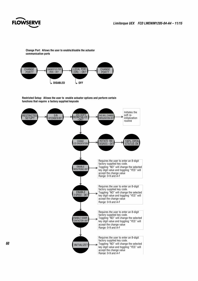
Limitorque UEX FCD LMENIM1205-04-A4 – 11/15
60
CHANGEPORT?
DIAGNOSTICS PORTIRDA – OK?
LOCAL PORT(ON) – OK?
CHANGEPORT?
DISABLED OFF
Change Port: Allows the user to enable/disable the actuator communication ports
RESTRICTEDSETUP?
S/NV#12345678-OK?
DO SOFTREINITIALIZE
–OK?
CHANGELCD ORIENTATION
ENABLEMODUTRONIC-OK?
ENABLE2-SPEED – OK?
ENABLE SSMRCONTACTOR–OK?
INITIALIZE?
THIS WILL CHANGECONFIGURATION–OK?
Initiates the soft re-initializationroutine
ROTATE 180DEGREES – OK?
100% OPENSTATUS OK
Requires the user to enter an 8-digit factory supplied key code.Toggling “NO” will change the selected key digit value and toggling “YES” will accept the change valueRange: 0-9 and A-F
Requires the user to enter an 8-digit factory supplied key code.Toggling “NO” will change the selected key digit value and toggling “YES” will accept the change valueRange: 0-9 and A-F
Requires the user to enter an 8-digit factory supplied key code.Toggling “NO” will change the selected key digit value and toggling “YES” will accept the change valueRange: 0-9 and A-F
Requires the user to enter an 8-digit factory supplied key code.Toggling “NO” will change the selected key digit value and toggling “YES” will accept the change valueRange: 0-9 and A-F
Restricted Setup: Allows the user to enable actuator options and perform certain functions that require a factory supplied keycode
61
Limitorque UEX FCD LMENIM1205-04-A4 – 11/15
flowserve.com
15 UEX Wiring Diagrams
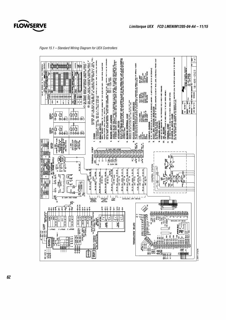
Limitorque UEX FCD LMENIM1205-04-A4 – 11/15
62
Figure 15.1 – Standard Wiring Diagram for UEX Controllers
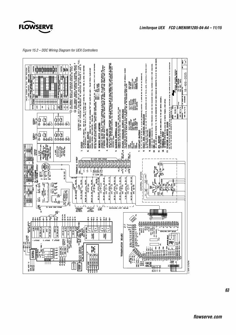
63
Limitorque UEX FCD LMENIM1205-04-A4 – 11/15
flowserve.com
Figure 15.2 – DDC Wiring Diagram for UEX Controllers
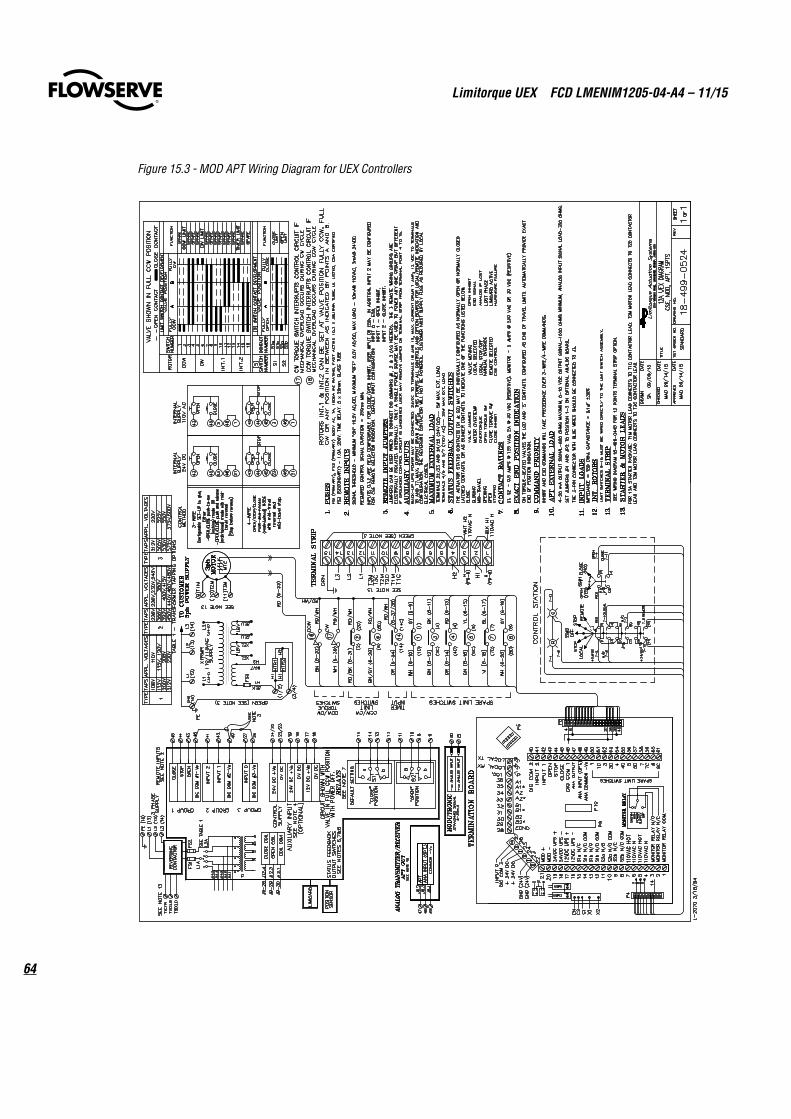
Limitorque UEX FCD LMENIM1205-04-A4 – 11/15
64
Figure 15.3 - MOD APT Wiring Diagram for UEX Controllers
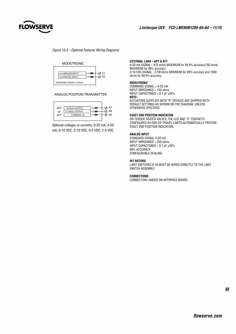
65
Limitorque UEX FCD LMENIM1205-04-A4 – 11/15
flowserve.com
Figure 15.4 – Optional Features Wiring Diagrams
EXTERNAL LOAD – APT & ATT4-20 mA SIGNAL - 470 ohms MAXIMUM for 99.9% accuracy/750 ohms MAXIMUM for 99% accuracy0-10 VDC SIGNAL - 2700 ohms MINIMUM for 99% accuracy and 1000 ohms for 99.9% accuracy.
MODUTRONICCOMMAND SIGNAL = 4-20 mAINPUT IMPEDANCE = 150 ohmsINPUT CAPACITANCE = 0.1 µF ±30%NOTE:ACTUATORS SUPPLIED WITH “R” DEVICES ARE SHIPPED WITH DEFAULT SETTINGS AS SHOWN ON THE DIAGRAM, UNLESS OTHERWISE SPECIFIED.
EXACT END POSITION INDICATIONON TORQUE-SEATED VALVES, THE LCD AND “S” CONTACTS CONFIGURED AS END-OF-TRAVEL LIMITS AUTOMATICALLY PROVIDE EXACT END POSITION INDICATION.
ANALOG INPUTSTANDARD SIGNAL 4-20 mAINPUT IMPEDANCE = 350 ohmsINPUT CAPACITANCE = 0.1 µF ±30% 99% ACCURACYCONFIGURABLE SCALING
INT ROTORS LIMIT SWITCHES 9-16 MUST BE WIRED DIRECTLY TO THE LIMIT SWITCH ASSEMBLY.
CONNECTIONSCONNECTION LANDED ON INTERFACE BOARD.
MODUTRONIC
STANDARD SIGNAL 4-20mA
2021
-ve ANALOG INPUT
+ve ANALOG INPUT
47
49
APTor
ATT
4-20mA OUTPUT
0-10VDC OUTPUT
COMMON -Ve
48
ANALOG POSITION TRANSMITTER
Optional voltages or currents; 0-20 mA, 4-20 mA, 0-10 VDC, 2-10 VDC, 0-5 VDC, 1-5 VDC
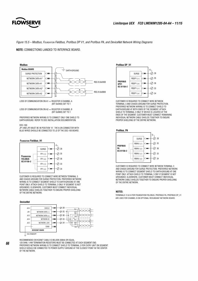
Limitorque UEX FCD LMENIM1205-04-A4 – 11/15
66
Figure 15.5 – Modbus, Foundation Fieldbus, Profibus DP V1, and Profibus PA, and DeviceNet Network Wiring Diagrams
NOTE: CONNECTIONS LANDED TO INTERFACE BOARD.
RECOMMENDED DEVICENET CABLE IS BELDEN 3084A OR EQUAL.120 OHM, 1/4W TERMINATION RESISTORS MUST BE CONNECTED AT EACH SEGMENT END.PREFERRED NETWORK WIRING IS TO CONNECT SHIELD TO TERMINAL 3 FOR EVERY UNIT ON SEGMENT. SHIELD SHOULD BE CONNECTED TO POWER SUPPLY GROUND AT THE CLOSEST POINT IN THE CENTER OF THE NETWORK.
DeviceNet
DEVICENET BOARD
EGND
RED
WHTBLK
BLU
NETWORK 0V
NETWORK +24V
NETWORK DATA (–)
NETWORK DATA (+)
SHIELDJ8.5
J8.1
J8.3
J8.4
J8.2
VIA STANDOFF
BLU
WHTBLK
RED
N/C
FOUNDATION FIELDBUSTERMINALS 29 AND 41 ARE REDUNDANT AND MAY BE USED FOR DAISY CHAIN CONFIGURATION.
NOTES:
LOSS OF COMMUNICATION ON A1 => REGISTER 9 CHANNEL A (BIT 0x0400) SET TO 1
LOSS OF COMMUNICATION ON A2 => REGISTER 9 CHANNEL B (BIT 0x0800) SET TO 1
PREFERRED NETWORK WIRING IS TO CONNECT ONLY ONE SHIELD TO EARTH/GROUND. REFER TO DDC INSTALLATION DOCUMENTATION.
33
34
28
35
36
NETWORK DATA-A2
NETWORK DATA-A2*
NETWORK DATA-A1
NETWORK DATA-A1*
Modbus BOARD
Modbus
EARTH/GROUNDSURGE PROTECTION
AREG 9.0x0400
REG 9.0x0800B
CUSTOMER IS REQUIRED TO CONNECT WIRE BETWEEN TERMINAL 3 AND CHASIS GROUND FOR SURGE PROTECTION. PREFERRED NETWORK WIRING IS TO CONNECT SHIELD TO EARTH/GROUND AT BOTH ENDS OF THE SEGMENT. ATTACH SHIELD TO TERMINAL 3 ONLY IF DEVICE IS LOCATED AT THE ENDS OF THE SEGMENT. CUSTOMER MUST CONNECT REMAINING INDIVIDUAL NETWORK CABLE SHIELDS TOGETHER TO ENSURE PROPER SHIELDING OF THE ENTIRE NETWORK.
PBDP1 (+)
PBDP1 (–)PROFIBUS DPV1 IEC 61158–2
Profibus DP_V1
SURGE
CUSTOMER IS REQUIRED TO CONNECT WIRE BETWEEN TERMINAL 3 AND CHASIS GROUND FOR SURGE PROTECTION. PREFERRED NETWORK WIRING IS TO CONNECT SEGMENT SHIELD TO EARTH/GROUND AT ONE POINT ONLY. ATTACH SHIELD TO TERMINAL 3 ONLY IF SEGMENT IS NOT GROUNDED. ELSEWHERE, CUSTOMER MUST CONNECT INDIVIDUAL NETWORK CABLE SHIELDS TOGETHER TO ENSURE PROPER SHIELDING OF THE ENTIRE NETWORK.
FF1 (+)
FF1 (–)
FF1 (+)
FF1 (–)FOUNDATION FIELDBUS IEC 61158–2
FOUNDATION Fieldbus_H1
SURGE
CUSTOMER IS REQUIRED TO CONNECT WIRE BETWEEN TERMINAL 3 AND CHASIS GROUND FOR SURGE PROTECTION. PREFERRED NETWORK WIRING IS TO CONNECT SEGMENT SHIELD TO EARTH/GROUND AT ONE POINT ONLY. ATTACH SHIELD TO TERMINAL 3 ONY IF SEGMENT IS NOT GROUNDED. ELSEWHERE, CUSTOMER MUST CONNECT INDIVIDUAL NETWORK CABLE SHIELDS TOGETHER TO ENSURE PROPER SHIELDING OF THE ENTIRE NETWORK.
PBPA1 (+)
PBPA1 (–)
PBPA1 (+)
PBPA1 (–)PROFIBUSPAIEC 61158–2
Profibus_PA
SURGE
PBDP1 (+)
PBDP1 (–)
DDC-100:JP1 AND JP2 MUST BE IN POSITION “A”. THE 6-[IN CONNECTOR WITH BLUE WIRES SHOULD BE CONNECTED TO J2 OF THE DDC-100 BOARD.
33
34
28
35
36
33
34
28
35
36
33
34
28
35
36
33
34
28
35
36
TERMINALS 13 &14 FOR FOUNDATION FIELDBUS, PROFIBUS PA, PROFIBUS DP_V1 ARE USED FOR CHANNEL B ON OPTIONAL REDUNDANT NETWORK BOARD.

67
Limitorque UEX FCD LMENIM1205-04-A4 – 11/15
flowserve.com
16.1 Network Wiring – ModbusPlease consult LMENIM2329 for detailed installation instructions.
• Belden 3105A Specifications
Total cable length between repeaters or nodes with repeaters:
• @ 9.6 kbps: 11500 ft. (3.5 km)
• @ 19.2 kbps: 5750 ft. (1.7 km)
Key Specifications
• Resistance/1000 ft = 22 AWG (7 x 30) 14.7 ohms each conductor (29.4 ohms for the pair)
• Capacitance/ft. = 11.0 pF (conductor-to-conductor)
• Capacitance/ft. = 20.0 pF (conductor-to-shield)
• Belden 3074F specifications
Total cable length between repeaters or nodes with repeaters:
• @ 9.6 kbps: 15000 ft. (4.5 km)
• @ 19.2 kbps: 7500 ft. (2.2 km)
Key Specifications
• Resistance/1000 ft = 18 AWG (7x26) 6.92 ohms each conductor (13.84 ohms for the pair)
• Capacitance/ft. = 14 pF (conductor-to-conductor)
• Capacitance/ft. = 14 pF (conductor-to-shield)
• Belden 9841 specifications
16 Network Protocol Connections
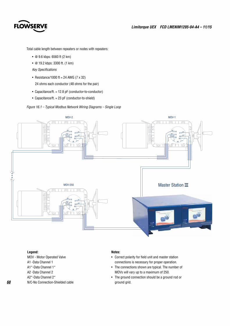
Limitorque UEX FCD LMENIM1205-04-A4 – 11/15
68
Total cable length between repeaters or nodes with repeaters:
• @ 9.6 kbps: 6560 ft (2 km)
• @ 19.2 kbps: 3300 ft. (1 km)
Key Specifications
• Resistance/1000 ft = 24 AWG (7 x 32)
24 ohms each conductor (48 ohms for the pair)
• Capacitance/ft. = 12.8 pF (conductor-to-conductor)
• Capacitance/ft. = 23 pF (conductor-to-shield)
Figure 16.1 – Typical Modbus Network Wiring Diagrams – Single Loop
Legend:
MOV - Motor Operated Valve
A1 -Data Channel 1
A1*-Data Channel 1*
A2 -Data Channel 2
A2*-Data Channel 2*
N/C-No Connection
-Shielded cable
Notes:
• Correct polarity for field unit and master station
connections is necessary for proper operation.
• The connections shown are typical. The number of
MOVs will vary up to a maximum of 250.
• The ground connection should be a ground rod or
ground grid.
•••
4115
A2
A2*
29
A1
A1*30
16
ShieldN/C
4115
A2
A2*
29
A1
A1*30
16
ShieldN/C
4115
A2
A2*
29
A1
A1*30
16
ShieldN/C
MOV-1MOV-2
MOV-250
Legend:MOV - Motor Operated ValveA1 -Data Channel 1A1*-Data Channel 1*A2 -Data Channel 2A2*-Data Channel 2*N/C-No Connection-Shielded cable
Notes:• Correct polarity for field unit and master station
connections is necessary for proper operation.• The connections shown are typical. The number of
MOVs will vary up to a maximum of 250.• The ground connection should be a ground rod or
ground grid.

69
Limitorque UEX FCD LMENIM1205-04-A4 – 11/15
flowserve.com
16.2 Network Wiring – Foundation Fieldbus H1Please refer to LMENIM2330 for detailed installation instructions.
Limitorque’s Foundation Fieldbus field unit conforms to open Fieldbus standard IEC 61158. It is suitable for use on the H1 highway and uses a twisted-pair cable for connection to the highway.
The UEX FF field unit fits in the actuator in the sealed electrical housing. All adjustments to the UEX FF settings may be made over the Foundation Fieldbus data highway using a network configuration tool.
The UEX FF unit may command its actuator to open, stop, close, move to a set position, or perform an emergency shutdown operation. Commands to the unit come over the network from the host system, which may be a PC, Distributed Control System (DCS), Programmable Logic Controller (PLC), or some other microprocessor-based device. Commands may also be generated in another network actuator or device and transmitted over fieldbus using peer-to-peer, publisher/subscriber communication.
A fieldbus device is an intelligent device within the actuator that can send multiple variables to the control system over a high-resolution and distortion-free digital communication network. The device provides control and self-test capabilities, which allow abnormal conditions to be easily and immediately identified before an unplanned shutdown.
Additional features and benefits are:
• Reduces cost of wiring and installation – existing wiring and multi-drop connections can be used.
• Interoperable devices – devices from different suppliers can communicate with one another on the same network.
A typical UEX FF system is shown in Figure 16.2.
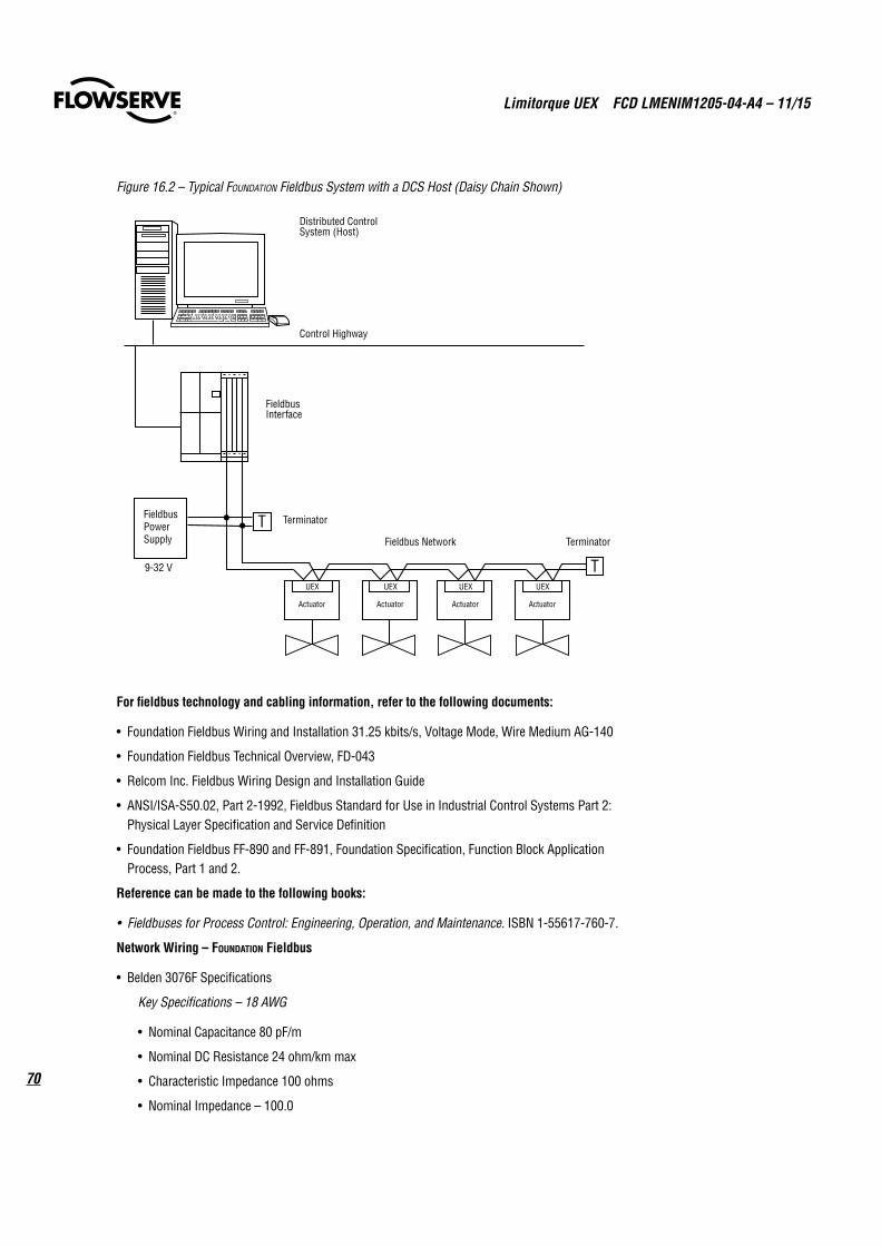
Limitorque UEX FCD LMENIM1205-04-A4 – 11/15
70
Figure 16.2 – Typical Foundation Fieldbus System with a DCS Host (Daisy Chain Shown)
Distributed Control System (Host )
Control Highway
Fieldbus Inte rf ace
UEX
Actuator
UEX
Actuator
UEX
Actuator
UEX
Actuator
T erminator
T erminator Fieldbus Network
Fieldbus Power Supply
9-32 V
For fieldbus technology and cabling information, refer to the following documents:
• Foundation Fieldbus Wiring and Installation 31.25 kbits/s, Voltage Mode, Wire Medium AG-140
• Foundation Fieldbus Technical Overview, FD-043
• Relcom Inc. Fieldbus Wiring Design and Installation Guide
• ANSI/ISA-S50.02, Part 2-1992, Fieldbus Standard for Use in Industrial Control Systems Part 2: Physical Layer Specification and Service Definition
• Foundation Fieldbus FF-890 and FF-891, Foundation Specification, Function Block Application Process, Part 1 and 2.
Reference can be made to the following books:
• Fieldbuses for Process Control: Engineering, Operation, and Maintenance. ISBN 1-55617-760-7.
Network Wiring – Foundation Fieldbus
• Belden 3076F Specifications
Key Specifications – 18 AWG
• Nominal Capacitance 80 pF/m
• Nominal DC Resistance 24 ohm/km max
• Characteristic Impedance 100 ohms
• Nominal Impedance – 100.0
71
Limitorque UEX FCD LMENIM1205-04-A4 – 11/15
flowserve.com
16.3 Network Wiring – Profibus DP and PAPlease refer to LMENIM2336 for detailed installation instructions.
Profibus is based on RS 485 communication. The standard EN 50170 specifies the cable for use with Profibus DP and PA. Table 16.1 shows specifications that need to be fulfilled by the Profibus cable.
Table 16.1 – Specifications for the Profibus CableParameter Type – Profibus DP
Impedance 135 to 165 ohm/3 to 20 MHz
Capacity < 30 pF/m
Resistance < 110 ohm/km
Wire gauge > 0.64 mm
Conductor area > 0.34 mm2
The Profibus DP cable is a shielded twisted pair cable.
In general, there are two different types of cables available. The most commonly used cable has solid wire for the Profibus line.
When there is a need for more flexiblity (bending) and higher environmental resistance, a cable with stranded wire for the Profibus line and special jackets shall be used.
Limitorque recommends the use of:
• Belden 3079A Specifications, 22 AWG, shielded, solid two conductor
Key Specifications
• Capacitance/ft = 8.5 pF
• Nominal Impedance (ohms) – 150.0
Network Wiring – Profibus PA – Belden 3076F
Please refer to IEC 61158 and ANSI/ISA S.50.02 Part 2-1992 for network wiring guidelines.
Maximum number of devices on a segment = 32 (including repeaters)
Table 16.2 – Maximum Segment Length
Data transfer rate in kbit/s 9.6 19.2 45.45 93.75 187.5 500 1500 3000 6000 12000
Maximum segment length in m
1200 1200 1200 1200 1000 400 200 100 100 100
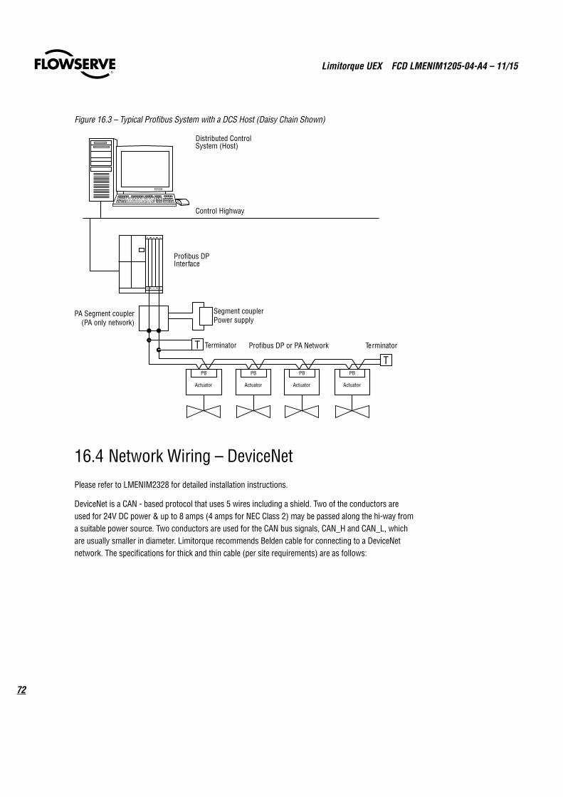
Limitorque UEX FCD LMENIM1205-04-A4 – 11/15
72
Figure 16.3 – Typical Profibus System with a DCS Host (Daisy Chain Shown)
Distributed ControlSystem (Host)
Control Highway
Profibus DPInterface
PB
Actuator
PB
Actuator
PB
Actuator
PB
Actuator
Terminator TerminatorProfibus DP or PA Network
Segment couplerPower supply
PA Segment coupler(PA only network)
16.4 Network Wiring – DeviceNetPlease refer to LMENIM2328 for detailed installation instructions.
DeviceNet is a CAN - based protocol that uses 5 wires including a shield. Two of the conductors are used for 24V DC power & up to 8 amps (4 amps for NEC Class 2) may be passed along the hi-way from a suitable power source. Two conductors are used for the CAN bus signals, CAN_H and CAN_L, which are usually smaller in diameter. Limitorque recommends Belden cable for connecting to a DeviceNet network. The specifications for thick and thin cable (per site requirements) are as follows:
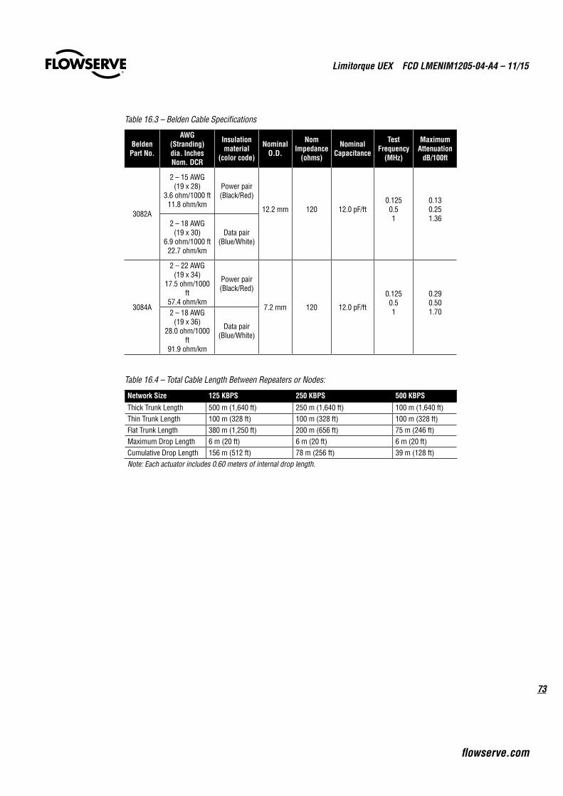
73
Limitorque UEX FCD LMENIM1205-04-A4 – 11/15
flowserve.com
Table 16.3 – Belden Cable Specifications
Belden Part No.
AWG (Stranding) dia. Inches Nom. DCR
Insulation material
(color code)
Nominal O.D.
Nom Impedance
(ohms)
Nominal Capacitance
Test Frequency
(MHz)
Maximum Attenuation
dB/100ft
3082A
2 – 15 AWG (19 x 28)
3.6 ohm/1000 ft 11.8 ohm/km
Power pair (Black/Red)
12.2 mm 120 12.0 pF/ft 0.125 0.5 1
0.13 0.25 1.36
2 – 18 AWG (19 x 30)
6.9 ohm/1000 ft 22.7 ohm/km
Data pair (Blue/White)
3084A
2 – 22 AWG (19 x 34)
17.5 ohm/1000 ft
57.4 ohm/km
Power pair (Black/Red)
7.2 mm 120 12.0 pF/ft
0.125 0.5 1
0.29 0.50 1.70 2 – 18 AWG
(19 x 36) 28.0 ohm/1000
ft 91.9 ohm/km
Data pair (Blue/White)
Table 16.4 – Total Cable Length Between Repeaters or Nodes:
Network Size 125 KBPS 250 KBPS 500 KBPS
Thick Trunk Length 500 m (1,640 ft) 250 m (1,640 ft) 100 m (1,640 ft)Thin Trunk Length 100 m (328 ft) 100 m (328 ft) 100 m (328 ft)Flat Trunk Length 380 m (1,250 ft) 200 m (656 ft) 75 m (246 ft)Maximum Drop Length 6 m (20 ft) 6 m (20 ft) 6 m (20 ft)Cumulative Drop Length 156 m (512 ft) 78 m (256 ft) 39 m (128 ft)Note: Each actuator includes 0.60 meters of internal drop length.
Limitorque UEX FCD LMENIM1205-04-A4 – 11/15
74
17 How to Order Parts
To order parts or obtain further information about your Limitorque L120 valve actuators, contact your local Limitorque distributor sales office, or:
Flowserve Limitorque
5114 Woodall Road P.O. Box 11318 Lynchburg, VA 24506-1318 Telephone (434) 528-4400 Fax (434) 845-9736
All inquiries or orders must be accompanied by the following information:
1. Actuator Size
2. Limitorque Order Number
3. Limitorque Serial Number
75
Limitorque UEX FCD LMENIM1205-04-A4 – 11/15
flowserve.com
18 Regulatory Information
flowserve.com
To find your local Flowserve Limitorque representative visit www.limitorque.com or call 1 434 528 4400
FCD LMENIM1205-04-A4 Printed in USA. November 2015
Flowserve Corporation has established industry leadership in the design and manufacture of its products. When properly selected, this Flowserve product is designed to perform its intended function safely during its useful life. However, the purchaser or user of Flowserve products should be aware that Flowserve products might be used in numerous applications under a wide variety of industrial service conditions. Although Flowserve can (and often does) provide general guidelines, it cannot provide specific data and warnings for all possible applications. The purchaser/user must therefore assume the ultimate responsibility for the proper sizing and selection, installation, operation, and maintenance of Flowserve products. The purchaser/user should read and understand the Installation Operation Maintenance (IOM) instructions included with the product, and train its employees and contractors in the safe use of Flowserve products in connection with the specific application.
While the information and specifications contained in this literature are believed to be accurate, they are supplied for informative purposes only and should not be considered certified or as a guarantee of satisfactory results by reliance thereon. Nothing contained herein is to be construed as a warranty or guarantee, express or implied, regarding any matter with respect to this product. Because Flowserve is continually improving and upgrading its product design, the specifications, dimensions and information contained herein are subject to change without notice. Should any question arise concerning these provisions, the purchaser/user should contact Flowserve Corporation at any one of its worldwide operations or offices.
© 2015 Flowserve Corporation, Irving, Texas, USA. Flowserve is a registered trademark of Flowserve Corporation.
Flowserve Corporation
United States Flowserve Limitorque 5114 Woodall Road P.O. Box 11318 Lynchburg, VA 24506-1318 Phone: 434-528-4400 Fax: 434-845-9736
England Flowserve Limitorque Euro House Abex Road Newbury Berkshire, RG14 5EY United Kingdom Phone: 44-1-635-46999 Fax: 44-1-635-36034
Singapore Limitorque Asia, Pte., Ltd. 12, Tuas Avenue 20 Singapore 638824 Phone: 65-6868-4628 Fax: 65-6862-4940
China Limitorque Beijing, Pte., Ltd. RM A1/A2 22/F, East Area, Hanwei Plaza No. 7 Guanghua Road, Chaoyang District Beijing 100004, Peoples Republic of China Phone: 86-10-5921-0606 Fax: 86-10-6561-2702
India Flowserve Limitorque Plot No. #4, 1 A, Road No. 8, EPIP Whitefield, Bangalore – 560066 Karnataka India Phone: 91-80-40146200 Fax: 91-80-28410286
Italy Flowserve Limitorque Fluid Power Systems Via Rio Vallone 17 20883 Mezzago MB Italy Phone: 39-039-620601 Fax: 39-039-62060 213