Embed Size (px)
Citation preview

for Huawei GPON Systems
User Guide
version 01

Table of contents
1. Introduction ............................................................................................................... 3 2. System structure ........................................................................................................ 3
2.1. Components ..................................................................................................... 3 2.2. IP network structure .......................................................................................... 4
2.2.1. IP networks and groups................................................................................ 4 2.2.2. IP address assignment strategy ................................................................... 4
2.3. Clients and terminal nodes .............................................................................. 5 3. Web interface – general overview ......................................................................... 5
3.1. Login .................................................................................................................. 5 3.2. Dashboard ........................................................................................................ 6 3.3. Searches and datatable settings ................................................................... 7
4. Web interface - menu structure .............................................................................. 9 4.1. User menu ........................................................................................................ 10 4.2. FTTX Active devices ........................................................................................ 11 4.3. FTTX ................................................................................................................... 13
4.3.1. Active device list ........................................................................................ 13 4.3.2. Headend ..................................................................................................... 13 4.3.3. OLT ............................................................................................................... 13 4.3.4. Networkgroup ............................................................................................. 16 4.3.5. Package ...................................................................................................... 16 4.3.6. IP network .................................................................................................... 17 4.3.7. IP pool .......................................................................................................... 19 4.3.8. Optical device – list and registration ........................................................ 20 4.3.9. Optical device - type ................................................................................ 21 4.3.10. Optical device – Model ........................................................................... 22 4.3.11. Terminal node ........................................................................................... 22 4.3.12. Todo ........................................................................................................... 28
4.4. IP address ........................................................................................................ 29 4.5. User ................................................................................................................... 29 4.6. Permission roles ............................................................................................... 30 4.7. Client ................................................................................................................ 31 4.8. City ................................................................................................................... 32 4.9. Street ................................................................................................................ 32 4.10. Manufacturer .................................................................................................. 33 4.11. Supplier ............................................................................................................ 33 4.12. VOIP provider .................................................................................................. 33 4.13. Other ................................................................................................................ 34
4.13.1. Server config ............................................................................................. 34 4.13.2. User logins .................................................................................................. 34
5. Provisioning process ................................................................................................ 34

1. Introduction
FiberVU for Huawei GPON systems (“FiberVU”) is a service-oriented management and provisioning
software tool which can configure and maintain internet and voice services for GPON subscribers on
the network.
Main features:
- Separated client (subscriber)and terminal node (service point) management
- ONT (ONU) management
- Generating configuration files and performing configurations tasks on the devices
- DHCP service for ONTs and CPEs including built-in MTA devices
- Customized ACS to provide TR069 configuration of the ONT’s built-in CPEs
- Logging features to provide graphical information about the main data from the network
- Feature rich API to connect external systems
This document describes the features and functions of the system GUI and provides examples to
support daily tasks.
2. System structure 2.1. Components
FiberVU can be divided into four main components:
- Web interface
o The interface has a responsive structure. Through the web interface, the user can manage the subscribers and devices, as well as control and monitor the network
- Application servers
o These servers are handling backends tasks, like configuration or device management
- System services and additional functions, including API
o These are related to the application servers and provide specific services, using the
configuration files or other data sets which are provided by the main application
servers
- Database engine
o Each component of the system is connected to a database engine, which provides a comprehensive operation during the whole provisioning and operation process
2.2. IP network structure 2.2.1. IP networks and groups
FiberVU assigns dynamic IP addresses for ONUs and built-in MTAs where this is applicable. Dynamic or static IP addresses are assigned for CPE devices, like built-in routers, wireless routers, subscriber PCs, etc.
These processes are happening automatically based on the settings of the system as well as the package parameters of the terminal node.
IP address ranges can be separated in different network groups. In a network group, there must be IP address ranges for ONUs, MTAs and CPE devices.
This grouping enables the service provider to differentiate terminal nodes by IP ranges too. For example, packages for business services will use dedicated ONU and CPE IP networks.
2.2.2. IP address assignment strategy
In the case of router type ONUs, the device is getting an IP address after ONU registration. Based on the system settings, the system will identify the ONU and its terminal node, then give a dynamic IP address.
If VoIP service is also enabled for the terminal node, an MTA IP address is also assigned, which is selected from the MTA IP pool.
The CPE device also receives an IP address. The System identifies the request based on the serial number of the ONU as a remote ID so according the terminal node and its package settings, a proper (dynamic or static) device IP will be offered.
All IP operations are logged into the database.
2.3. Clients and terminal nodes A client is a person or company who is using and paying for the internet service. One client may have several terminal nodes working independently.
The terminal node is the service point, where the subscription is used. Each terminal node has several parameters:
- address, contact and contract information
- one subscription (package)
- one ONU

- VoIP information (service provider, phone number, account credentials)
- status (e.g. connected)
The terminal node is working only if it has a package and an ONU is assigned and connected or the “connection in progress” status is selected. These terminal nodes are counted only for licensing purposes.
3. Web interface – general overview 3.1. Login
After entering the URL of the system in your web browser, the login page will be displayed:
Login page
Please enter your username and password and use the “Login” button to login into the system.
The recommended browsers are Google Chrome, Mozilla Firefox, and Microsoft EDGE.
The web interface is a responsive GUI, so you can use your mobile device (tablet, smartphone) as well. Displayed data will be adjusted automatically to match your display resolution.
All date and time information is displayed according to the current time zone setting of your browser.
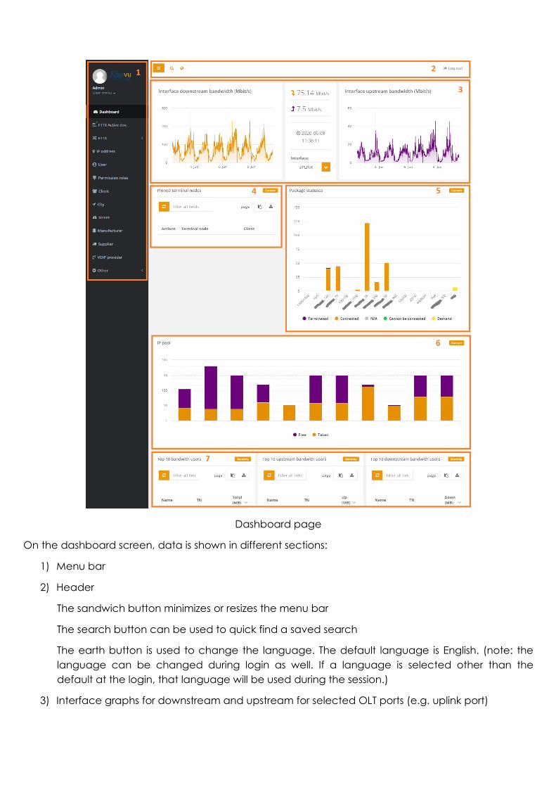
3.2. Dashboard The dashboard is the default page after login. It provides overview information about network and terminal nodes which can be used.
Dashboard page
On the dashboard screen, data is shown in different sections:
1) Menu bar
2) Header
The sandwich button minimizes or resizes the menu bar
The search button can be used to quick find a saved search
The earth button is used to change the language. The default language is English. (note: the language can be changed during login as well. If a language is selected other than the default at the login, that language will be used during the session.)
3) Interface graphs for downstream and upstream for selected OLT ports (e.g. uplink port)

You can choose the port from the drop-down list. The graph can be zoomed in by selecting an area from the graph. You can go back to the normal view by clicking the “Reset zoom” button in the top right corner of the graph.
4) Pinned terminal nodes
Each user of the system can pin one or several terminal nodes for quick access. The terminal node can be added to this list from the “User menu” in Section 1 (see Dashboard page screenshot above)
5) Package status
This chart shows the distribution of the packages and their statuses in the system.
All statuses are shown on the chart by default. You can select or deselect a status by clicking the name of it.
6) IP pool
This chart shows all configured IP pools and their current utilization data.
7) Top bandwidth users
System shows top 10 data traffic users download, upload and combined.
3.3. Searches and data table settings The search boxes in the web GUI are always free text searches. It means that anything can be added there and all matches will be shown automatically from the currently used list.
All data table results can be copied to the clipboard, or can be downloaded in a CSV file with these icons:
This example shows a search entry and its result, using it in the optical devices list.
The advanced search function opens a modal window where the search can be narrowed down for specific fields (e.g. serial number only). These searches can be saved as a predefined search for later usage by using the “Save” or “Save as” function.
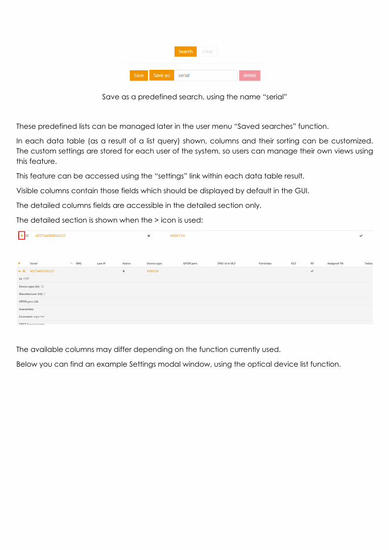
Save as a predefined search, using the name “serial”
These predefined lists can be managed later in the user menu “Saved searches” function.
In each data table (as a result of a list query) shown, columns and their sorting can be customized. The custom settings are stored for each user of the system, so users can manage their own views using this feature.
This feature can be accessed using the “settings” link within each data table result.
Visible columns contain those fields which should be displayed by default in the GUI.
The detailed columns fields are accessible in the detailed section only.
The detailed section is shown when the > icon is used:
The available columns may differ depending on the function currently used.
Below you can find an example Settings modal window, using the optical device list function.

Device list settings
4. Web interface - menu structure
The menu bar can be accessed from the left side.
Additional items are available from the main menu points using the arrows. These items will appear as a list or submenu items.

4.1. User menu
User menu
This menu shows name of the current user and gives quick access to saved items related to the profile.
1) Pinned terminal nodes
You can manage your pinned terminal nodes list here. New item can be added by using the add button. This opens a modal window where the terminal node can be selected from a list.
The search box is a free text search, so anything is added there, and all matches will be shown automatically.
2) Data table settings
You can manage your previously defined custom data table settings here.
List of the saved settings
3) Saved searches
You can manage your previously defined custom data table settings here.
4) Logout

The user session expires after 20 minutes of inactivity. If system is used, session is automatically extended.
After a long period of inactivity, the system shows a warning where you can choose to stay in before automatic logout.
You can use the Logout function to quit and close your session.
4.2. FTTX Active devices This list is one of the most frequently used functions of the system. It queries one of your OLTs based on your selection and shows the current status of all the connected devices. This link is a quick access link for the FTTX->Active device list (4.3.1)
The system is automatically pairing ONUs with current client and terminal node settings, so you see device information, status, installation address, etc., in one single query. The data fields are links to provide quick access to the specific pages (e.g. ONU, or terminal node).
First, you need to select OLT to query from the drop-down list. In the case of a single OLT, the selection is done automatically.
Secondly, you need to select the list type.
Full will provide all registered ONUs, Auto find will show physically connected, but not registered ONUs only.
Active device list selection
As a result, you will see the following example:
The run state in the example is offline, so it is registered, and it was connected to the OLT, but currently not.
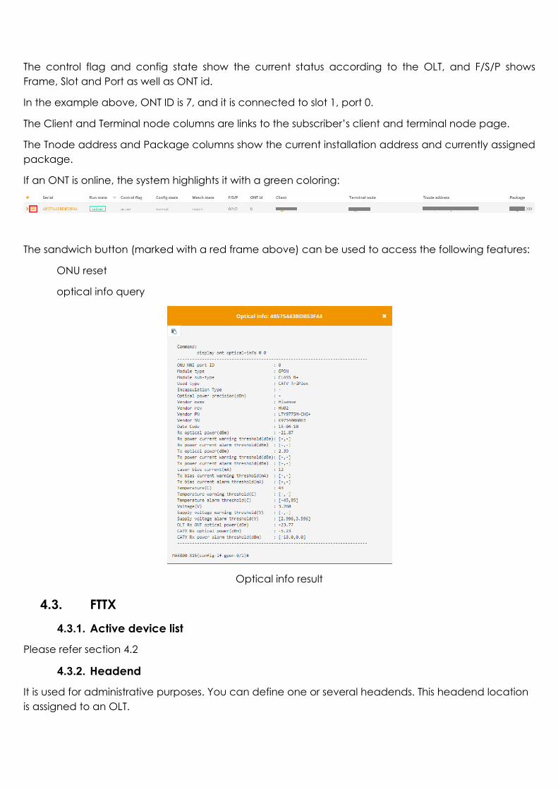
The control flag and config state show the current status according to the OLT, and F/S/P shows Frame, Slot and Port as well as ONT id.
In the example above, ONT ID is 7, and it is connected to slot 1, port 0.
The Client and Terminal node columns are links to the subscriber’s client and terminal node page.
The Tnode address and Package columns show the current installation address and currently assigned package.
If an ONT is online, the system highlights it with a green coloring:
The sandwich button (marked with a red frame above) can be used to access the following features:
ONU reset
optical info query
Optical info result
4.3. FTTX 4.3.1. Active device list
Please refer section 4.2
4.3.2. Headend
It is used for administrative purposes. You can define one or several headends. This headend location is assigned to an OLT.

4.3.3. OLT
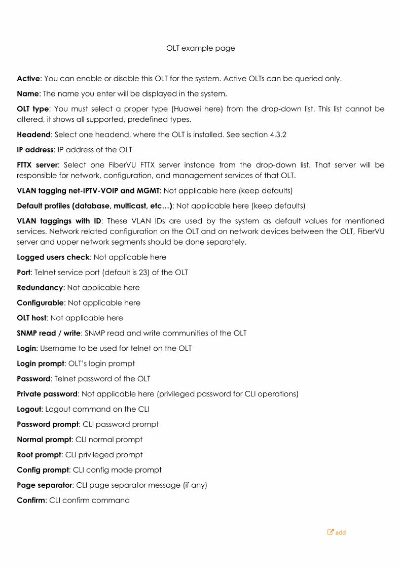
This function is used to register an OLT in the system.
OLT example page
Active: You can enable or disable this OLT for the system. Active OLTs can be queried only.
Name: The name you enter will be displayed in the system.
OLT type: You must select a proper type (Huawei here) from the drop-down list. This list cannot be altered, it shows all supported, predefined types.
Headend: Select one headend, where the OLT is installed. See section 4.3.2
IP address: IP address of the OLT
FTTX server: Select one FiberVU FTTX server instance from the drop-down list. That server will be responsible for network, configuration, and management services of that OLT.
VLAN tagging net-IPTV-VOIP and MGMT: Not applicable here (keep defaults)
Default profiles (database, multicast, etc…): Not applicable here (keep defaults)
VLAN taggings with ID: These VLAN IDs are used by the system as default values for mentioned services. Network related configuration on the OLT and on network devices between the OLT, FiberVU server and upper network segments should be done separately.
Logged users check: Not applicable here
Port: Telnet service port (default is 23) of the OLT
Redundancy: Not applicable here
Configurable: Not applicable here
OLT host: Not applicable here
SNMP read / write: SNMP read and write communities of the OLT
Login: Username to be used for telnet on the OLT
Login prompt: OLT’s login prompt
Password: Telnet password of the OLT
Private password: Not applicable here (privileged password for CLI operations)
Logout: Logout command on the CLI
Password prompt: CLI password prompt
Normal prompt: CLI normal prompt
Root prompt: CLI privileged prompt
Config prompt: CLI config mode prompt
Page separator: CLI page separator message (if any)
Confirm: CLI confirm command

Note: If data is not available for one of the fields which is required, you can use the button. After adding the data, you can go back and continue the registration
In the OLT section, there are additional submenus: Interface, Frame and Slot.
The interface submenu can be used to define port to be monitored for the system.
This example shows an ethernet port setting of an MA5800 OLT
Frame and slot are not applicable here.
4.3.4. Networkgroup
You can manage your existing and add a new network group here. The name and note can be added for each network group you have.
By default, “Default” is existing as a standard network group. For more information about network groups, please check section 2.2.1
4.3.5. Package
Internet and other IP related services (IPTV or VOIP) can be managed here. It declares bandwidth profiles (maximum download and upload rates), as well as IP address settings, so these profiles are referred to as a package.
Packages list
When a package is declared, the system is creating on all active OLTs the necessary traffic IP profiles using the down and up Mbit/s values of the package. It will be used later when a proper profile must be assigned during an ONU activation process.
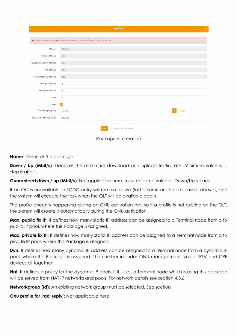
Package information
Name: Name of the package
Down / Up (Mbit/s): Declares the maximum download and upload traffic rate. Minimum value is 1, step is also 1.
Guaranteed down / up (Mbit/s): Not applicable here, must be same value as Down/Up values.
If an OLT is unavailable, a TODO entry will remain active (last column on the screenshot above), and the system will execute the task when the OLT will be available again.
The profile check is happening during an ONU activation too, so if a profile is not existing on the OLT, the system will create it automatically during the ONU activation.
Max. public fix IP: It defines how many static IP address can be assigned to a Terminal node from a fix public IP pool, where this Package is assigned.
Max. private fix IP: It defines how many static IP address can be assigned to a Terminal node from a fix private IP pool, where this Package is assigned.
Dyn: It defines how many dynamic IP address can be assigned to a Terminal node from a dynamic IP pool, where this Package is assigned. This number includes ONU management, voice, IPTV and CPE devices all together.
Nat: It defines a policy for the dynamic IP pools. If it is set, a Terminal node which is using this package will be served from NAT IP networks and pools. For network details see section 4.3.6
Networkgroup (id): An existing network group must be selected. See section
Onu profile for ‘rad_reply’: Not applicable here.

4.3.6. IP network
You need to define those IP networks, which are used on the OLTs or NAS devices configured in the system. It declares valid IP networks for the DHCP or the Radius servers (in case of PPPOE).
List of IP networks
IP network details
Name: Name of the network.
Networkgroup: An existing network group must be selected.

Network type: It defines the purpose of this network. A system predefined type must be selected. Available options are ATA (Voice), CPE, IPBOX (IPTV), and ONU
Network: A valid IP network segment should be added. E.g. 192.168.10.0/24
Gateway: Gateway IP of the network. This IP is used as a default gateway for all devices which are using this network.
DNS0: Primary DNS. This must be selected from the drop-down list.
DNS1: Secondary DNS
NAT: If it is enabled, this network will be handled as a network address translated (private IP) network.
PPPOE: Not selected: DHCP network (default), Selected: This network is used for PPPOE services and will be handled by the integrated radius server.
OLT: For DHCP operation, an existing OLT must be selected from the drop-down list. For each OLT you have, dedicated IP networks should be configured.
NAS: If PPPOE is selected, instead of OLT, a NAS device must be selected.
The NAS must be existing in the radius server configuration, and radius – NAS connection must be properly configured. Please contact FiberVU support when new NAS device is required.
4.3.7. IP pool
An IP pool must be defined within each network. These pools will be used by the DHCP server within the IP range you specify.
List of IP pools
Name: Name of the pool.
IP network: An existing IP network must be selected from the drop-down list.
First IP: First IP of the pool within the IP network.
Last IP: Last IP of the pool within the IP network.
Fix: If static IPs will be assigned from the pool, Fix must be selected. Otherwise, this pool will be used as a dynamic.
Leasetime: DHCP lease period in seconds.
Utilization: The number of currently used IP addresses in the pool.

IP pool details
4.3.8. Optical device – list and registration
This list shows the already added ONUs in the system, and new can be added using “add” link on the top of the page.
Optical device list
Serial: Serial number of the ONU
MAC: Not applicable here
Last IP: Shows last IP assignment to this ONU if the lease is not expired.
Active: If the ONU is assigned to a TN and that TN is in operational status.
Device type: Type of the ONU
GPON port: Not applicable here.
ONU id: Not applicable here.
Port Index: Not applicable here.
OLT: Shows the OLT where this ONU is assigned.
RF: If the ONU is an RF-port type, and the RF port is enabled, then RF is true. Otherwise false is displayed.
Assigned TN: Shows the terminal node, where this ONU is assigned.
To dos: Shows the number of to do tasks related this ONU.

ONU details
Serial number: The serial number of the ONU must be unique. Data here and serial number of the device must be identical.
Device type: A proper device type must be selected.
OLT: Select one OLT where this ONU is connected.
Guarantee, Comment, Description fields are optional.
MAC, Custom profiles fields are not applicable here.
4.3.9. Optical device - type
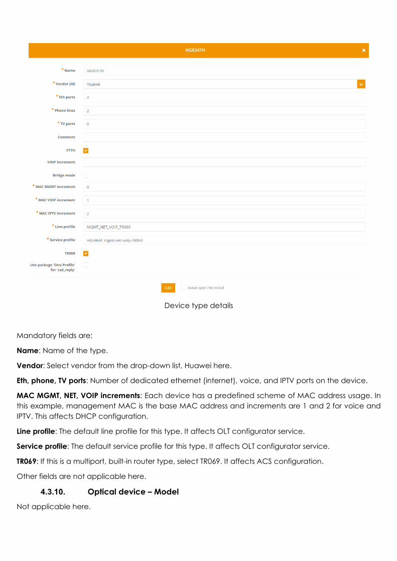
The device type defines capabilities of the ONU and the default values of the most important parameters, which are necessary to provision the device.
Device type details
Mandatory fields are:
Name: Name of the type.
Vendor: Select vendor from the drop-down list, Huawei here.
Eth, phone, TV ports: Number of dedicated ethernet (internet), voice, and IPTV ports on the device.
MAC MGMT, NET, VOIP increments: Each device has a predefined scheme of MAC address usage. In this example, management MAC is the base MAC address and increments are 1 and 2 for voice and IPTV. This affects DHCP configuration.
Line profile: The default line profile for this type. It affects OLT configurator service.
Service profile: The default service profile for this type. It affects OLT configurator service.
TR069: If this is a multiport, built-in router type, select TR069. It affects ACS configuration.
Other fields are not applicable here.
4.3.10. Optical device – Model
Not applicable here.
4.3.11. Terminal node
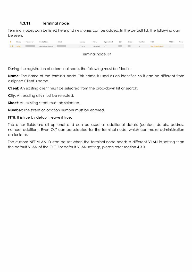
Terminal nodes can be listed here and new ones can be added. In the default list, the following can be seen:
Terminal node list
During the registration of a terminal node, the following must be filled in:
Name: The name of the terminal node. This name is used as an identifier, so it can be different from assigned Client’s name.
Client: An existing client must be selected from the drop-down list or search.
City: An existing city must be selected.
Street: An existing street must be selected.
Number: The street or location number must be entered.
FTTH: It is true by default, leave it true.
The other fields are all optional and can be used as additional details (contact details, address number addition). Even OLT can be selected for the terminal node, which can make administration easier later.
The custom NET VLAN ID can be set when the terminal node needs a different VLAN id setting than the default VLAN of the OLT. For default VLAN settings, please refer section 4.3.3

Add new terminal node
One terminal node has several parameters. Each parameter can be seen or set via dedicated tabs at the terminal node page:
The example terminal node page with tabs for terminal node “Lp9V”
PPPOE: PPPOE is turned off by default. If you enable it, the terminal node’s user and password can be added here. It affects central radius configuration.
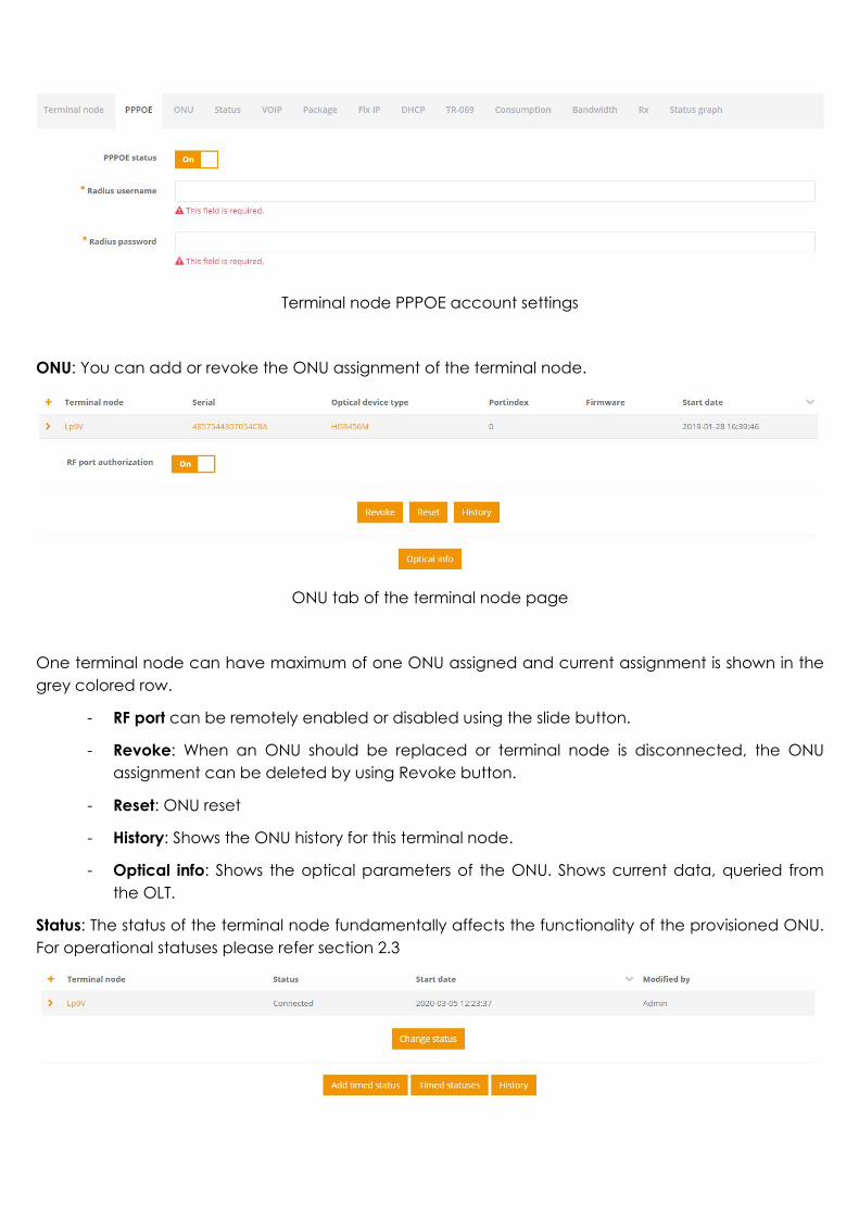
Terminal node PPPOE account settings
ONU: You can add or revoke the ONU assignment of the terminal node.
ONU tab of the terminal node page
One terminal node can have maximum of one ONU assigned and current assignment is shown in the grey colored row.
- RF port can be remotely enabled or disabled using the slide button.
- Revoke: When an ONU should be replaced or terminal node is disconnected, the ONU assignment can be deleted by using Revoke button.
- Reset: ONU reset
- History: Shows the ONU history for this terminal node.
- Optical info: Shows the optical parameters of the ONU. Shows current data, queried from the OLT.
Status: The status of the terminal node fundamentally affects the functionality of the provisioned ONU. For operational statuses please refer section 2.3
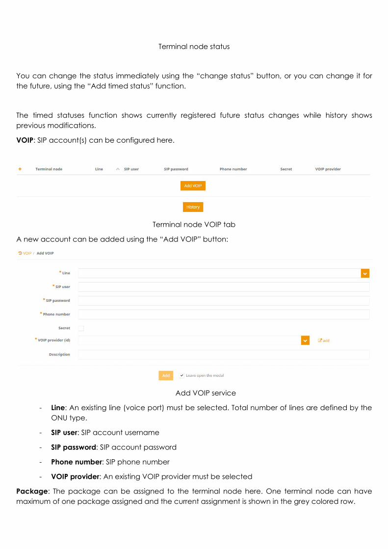
Terminal node status
You can change the status immediately using the “change status” button, or you can change it for the future, using the “Add timed status” function.
The timed statuses function shows currently registered future status changes while history shows previous modifications.
VOIP: SIP account(s) can be configured here.
Terminal node VOIP tab
A new account can be added using the “Add VOIP” button:
Add VOIP service
- Line: An existing line (voice port) must be selected. Total number of lines are defined by the ONU type.
- SIP user: SIP account username
- SIP password: SIP account password
- Phone number: SIP phone number
- VOIP provider: An existing VOIP provider must be selected
Package: The package can be assigned to the terminal node here. One terminal node can have maximum of one package assigned and the current assignment is shown in the grey colored row.

Package tab
If you need to change packages immediately, use the Change package function.
It is possible to change a package in the future, so you can use Add timed package in the same way as it is described in the Status change.
Fix IP: You can create a static IP assignment here for the terminal node.
Fix IP settings
- IP Network: An IP network must be selected.
- IP pool: A fix IP pool from the network above must be selected.
- IP: Select an IP from the pool above. The system will automatically provide you with the first available IP of the pool.
- MAC: While it is not mandatory, it is strongly recommended to enter the CPE device MAC address for the static IP assignment.
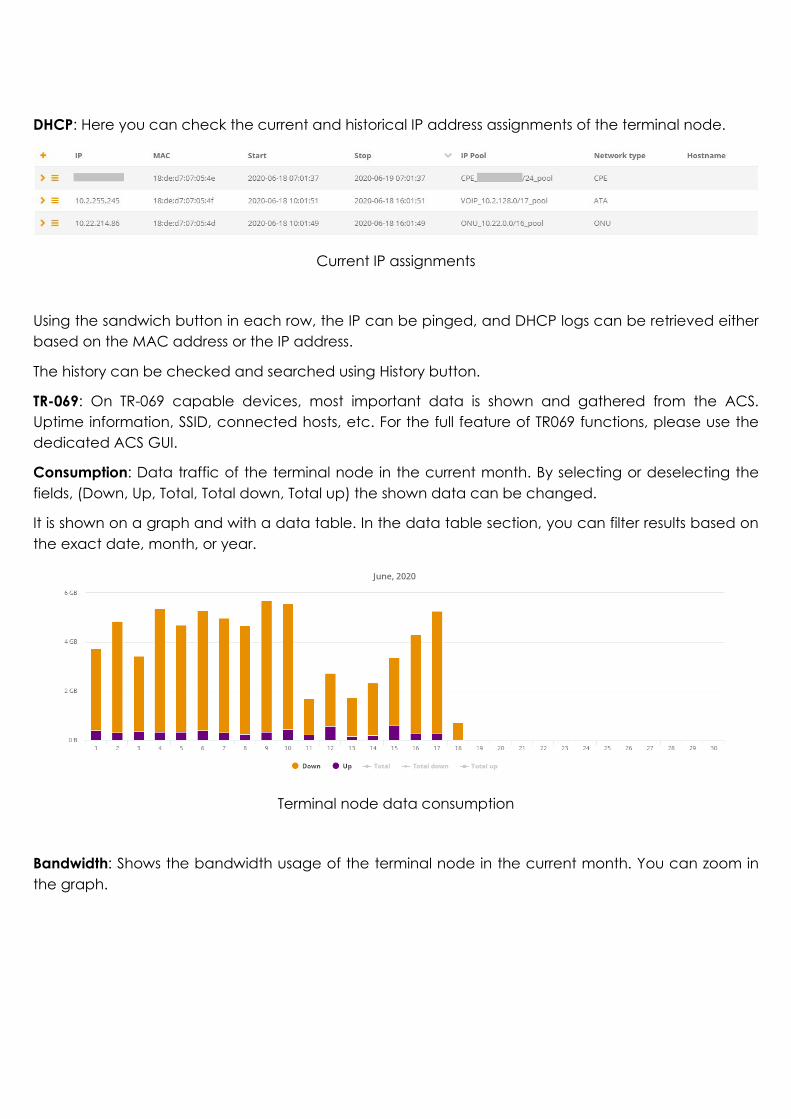
DHCP: Here you can check the current and historical IP address assignments of the terminal node.
Current IP assignments
Using the sandwich button in each row, the IP can be pinged, and DHCP logs can be retrieved either based on the MAC address or the IP address.
The history can be checked and searched using History button.
TR-069: On TR-069 capable devices, most important data is shown and gathered from the ACS. Uptime information, SSID, connected hosts, etc. For the full feature of TR069 functions, please use the dedicated ACS GUI.
Consumption: Data traffic of the terminal node in the current month. By selecting or deselecting the fields, (Down, Up, Total, Total down, Total up) the shown data can be changed.
It is shown on a graph and with a data table. In the data table section, you can filter results based on the exact date, month, or year.
Terminal node data consumption
Bandwidth: Shows the bandwidth usage of the terminal node in the current month. You can zoom in the graph.
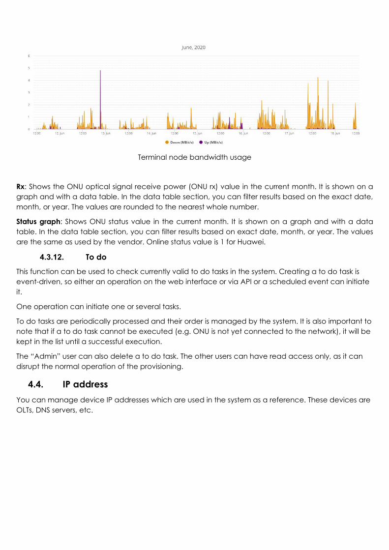
Terminal node bandwidth usage
Rx: Shows the ONU optical signal receive power (ONU rx) value in the current month. It is shown on a graph and with a data table. In the data table section, you can filter results based on the exact date, month, or year. The values are rounded to the nearest whole number.
Status graph: Shows ONU status value in the current month. It is shown on a graph and with a data table. In the data table section, you can filter results based on exact date, month, or year. The values are the same as used by the vendor. Online status value is 1 for Huawei.
4.3.12. To do
This function can be used to check currently valid to do tasks in the system. Creating a to do task is event-driven, so either an operation on the web interface or via API or a scheduled event can initiate it.
One operation can initiate one or several tasks.
To do tasks are periodically processed and their order is managed by the system. It is also important to note that if a to do task cannot be executed (e.g. ONU is not yet connected to the network), it will be kept in the list until a successful execution.
The “Admin” user can also delete a to do task. The other users can have read access only, as it can disrupt the normal operation of the provisioning.
4.4. IP address You can manage device IP addresses which are used in the system as a reference. These devices are OLTs, DNS servers, etc.

IP address details
Address: A valid IP address of the device or server.
Name: Related name
Note can be used to add additional information to this IP address.
4.5. User To access the web interface or the API, a valid user must be existing. Each user of the system can have a different permission role and can save their own preferences, searches, and data table settings.
Add user details
Name: Name of the user. (e.g. John Doe)
Username: A username for the login. (e.g. jdoe)
Password: Password for the user (should be repeated identically in confirm field).
Permission roles: At least one existing permission role must be selected, but the system allows you to select multiple items.

Email, Profile picture name, and Language are all optional. The default language is English (en).
4.6. Permission roles Permission roles are used to control user activity and the access of different functions in the system. Each role has a name which will be used as a reference in the User section. See 4.5
Read, Add, Edit, and Delete are standard permissions to select and many more are available which are function specific. Here is an example below for optical and active functions:
Permission example
You can freely disable or enable a permission; the system will automatically set the dependencies as well from the permission matrix.
4.7. Client The client is a person or company who is using and paying for the internet service.
In this function you can manage your existing clients and you can also register a new one.
For more details about clients please refer section 2.3
The client can have several different identifiers. You have the option to use external identifiers too, which can help matching a client with a 3rd party system record.
The following fields are mandatory:
Name: Name of the client. This field is not unique.
Identifier: Unique identifier of the client in the system.
City: An existing city must be selected.
Street: An existing street must be selected.
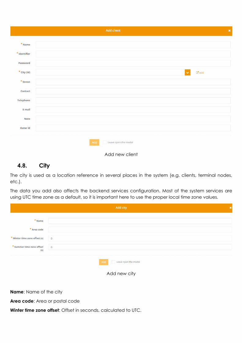
Add new client
4.8. City The city is used as a location reference in several places in the system (e.g. clients, terminal nodes, etc.).
The data you add also affects the backend services configuration. Most of the system services are using UTC time zone as a default, so it is important here to use the proper local time zone values.
Add new city
Name: Name of the city
Area code: Area or postal code
Winter time zone offset: Offset in seconds, calculated to UTC.
Summer time zone offset: Offset in seconds, calculated to UTC.
4.9. Street To provide a proper administration, and a possibility to have an exact match with the external systems, the streets must also be added in the system.
Add new street
Name: Name of the street.
City: An existing city must be selected.
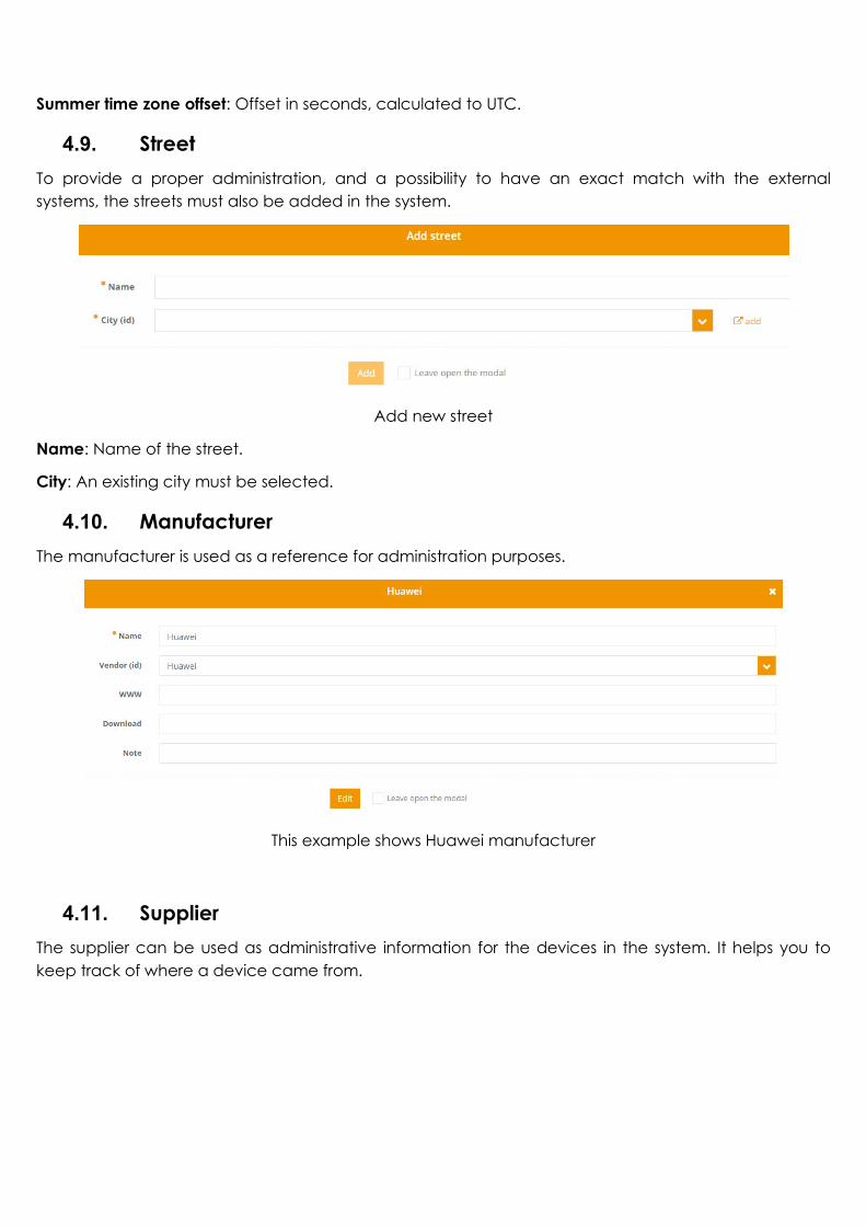
4.10. Manufacturer The manufacturer is used as a reference for administration purposes.
This example shows Huawei manufacturer
4.11. Supplier The supplier can be used as administrative information for the devices in the system. It helps you to keep track of where a device came from.

Add new supplier
4.12. VOIP provider This function enables you to add a VOIP service provider for provisioning purposes.
To enable a VOIP service for a subscriber, a VOIP-capable ONU, a VOIP provider, and at least one SIP account is needed.
Add new VOIP provider
Name: Name of the provider.
IP address: A valid IP address of the SIP server.
Port: SIP server port.
The MTA domain and Profile ID are not applicable here.
4.13. Other 4.13.1. Server config
The system settings for backend services. There are dedicated permissions to these settings in the permission roles (see section 4.6).

ZCorum strongly recommends allowing access to this function for administrator users only!
4.13.2. User logins
The current and previous user logins can be listed here.
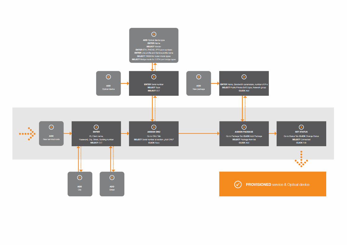
5. Provisioning process
The following page shows the flow chart of a sample terminal node provisioning using the web interface of the system.