Embed Size (px)
Citation preview
Tracer CH530™Control System for Scroll ChillersCGAM/CXAM 020-170
User Guide
CG-SVU06B-E4
General information
CG-SVU06B-E4
Foreword
These instructions are given as aguide to good practice in theinstallation, start-up, operation, andmaintenance by the user, of TraneCH530 chiller control system onscroll chillers. They do not containfull service procedures necessaryfor the continued successfuloperation of this equipment. Theservices of a qualified technicianshould be employed through themedium of a maintenance contractwith a reputable service company.Read this manual thoroughly beforeunit start-up.
Warnings and cautions
Warnings and Cautions appear atappropriate sections throughoutthis manual. Your personal safetyand the proper operation of thismachine require that you followthem carefully. The constructorassumes no liability for installationsor servicing performed byunqualified personnel.
WARNING! : Indicates a potentiallyhazardous situation which, if notavoided, could result in death orserious injury.
CAUTION! : Indicates a potentiallyhazardous situation which, if notavoided, may result in minor ormoderate injury. It may also beused to alert against unsafepractices or for equipment orproperty-damage-only accidents.
Safety recommendations
To avoid death, injury, equipmentor property damage, the followingrecommendations should beobserved during maintenance andservice visits:1. Disconnect the main power
supply before any servicing onthe unit.
2. Service work should be carriedout only by qualified andexperienced personnel.
Reception
On arrival, inspect the unit beforesigning the delivery note.
Reception in France only:
In case of visible damage: Theconsignee (or the siterepresentative) must specify anydamage on the delivery note,legibly sign and date the deliverynote, and the truck driver mustcountersign it. The consignee (orthe site representative) must notifyTrane Epinal Operations - Claimsteam and send a copy of thedelivery note. The customer (or thesite representative) should send aregistered letter to the last carrierwithin 3 days of delivery.
Reception in all countries except
France:
In case of concealed damage: Theconsignee (or the siterepresentative) must send aregistered letter to the last carrierwithin 7 days of delivery, claimingfor the described damage. A copyof this letter must be sent to TraneEpinal Operations - Claims team.
Note: for deliveries in France, evenconcealed damage must be lookedfor at delivery and immediatelytreated as visible damage.
© 2009 Trane
General information
3CG-SVU06B-E4
Warranty
Warranty is based on the generalterms and conditions of themanufacturer. The warranty is voidif the equipment is repaired ormodified without the writtenapproval of the manufacturer, if theoperating limits are exceeded or ifthe control system or the electricalwiring is modified. Damage due tomisuse, lack of maintenance orfailure to comply with themanufacturer's instructions orrecommendations is not covered bythe warranty obligation. If the userdoes not conform to the rules ofthis manual, it may entailcancellation of warranty andliabilities by the manufacturer.
Maintenance contract
It is strongly recommended that yousign a maintenance contract withyour local Service Agency. Thiscontract provides regularmaintenance of your installation bya specialist in our equipment.Regular maintenance ensures thatany malfunction is detected andcorrected in good time andminimizes the possibility thatserious damage will occur. Finally,regular maintenance ensures themaximum operating life of yourequipment. We would remind youthat failure to respect theseinstallation and maintenanceinstructions may result inimmediate cancellation of thewarranty.
Training
To assist you in obtaining the bestuse of it and maintaining it inperfect operating condition over along period of time, themanufacturer has at your disposal arefrigeration and air conditioningservice school. The principal aim ofthis is to give operators andtechnicians a better knowledge ofthe equipment they are using, orthat is under their charge. Emphasisis particularly given to theimportance of periodic checks onthe unit operating parameters aswell as on preventive maintenance,which reduces the cost of owningthe unit by avoiding serious andcostly breakdown.
Contents
CG-SVU06B-E44
General Information 2
Overview 5
DynaView Interface 6
Display Screens 8
Diagnostics 29
TechView Interface 46
Software Download 45
Overview
5CG-SVU06B-E4
The Trane CH530 control systemthat runs the chiller consists ofseveral elements:• The main processor collects
data, status, and diagnosticinformation and communicatescommands to the LLID (for LowLevel Intelligent Device) bus. Themain processor has an integraldisplay (DynaView).
• LLID bus. The main processorcommunicates to each input andoutput device (e.g. temperatureand pressure sensors, lowvoltage binary inputs, analoginput/output) all connected to afour-wire bus, rather than theconventional control architectureof signal wires for each device.
• The communication interface toa building automation system(BAS).
• A service tool to provide allservice/maintenance capabilities.Main processor and service tool(TechView) software isdownloadable fromwww.Trane.com. The process isdiscussed later in this sectionunder TechView Interface.DynaView provides busmanagement. It has the task ofrestarting the link, or filling in forwhat it sees as "missing" deviceswhen normal communicationshas been degraded. Use ofTechView may be required.
The CH530 uses the IPC3 protocolbased on RS485 signal technologyand communicating at 19.2 Kbaudto allow 3 rounds of data persecond on a 64-device network.Most diagnostics are handled by theDynaView. If a temperature orpressure is reported out of range bya LLID, the DynaView processes thisinformation and calls out thediagnostic. The individual LLIDs arenot responsible for any diagnosticfunctions.
Note: It is imperative that the CH530Service Tool (TechView) be used tofacilitate the replacement of anyLLID or reconfigure any chillercomponent.
Controls Interface
DynaView (picture on cover)
Each chiller is equipped with theDynaView interface. DynaView hasthe capability to display additionalinformation to the advancedoperator including the ability toadjust settings. Multiple screens areavailable and text is presented inmultiple languages as factory-ordered or can be easilydownloaded online.
TechView
TechView can be connected to theDynaView module and providesfurther data, adjustmentcapabilities, diagnosticsinformation, downloadablesoftware, and downloadablelanguages.
DynaView Interface
CG-SVU06B-E46
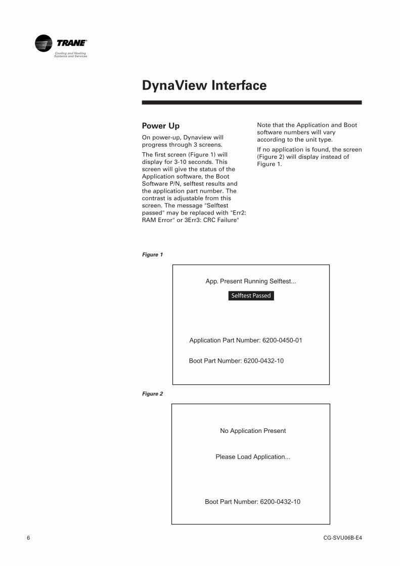
Power Up
On power-up, Dynaview willprogress through 3 screens.
The first screen (Figure 1) willdisplay for 3-10 seconds. Thisscreen will give the status of theApplication software, the BootSoftware P/N, selftest results andthe application part number. Thecontrast is adjustable from thisscreen. The message "Selftestpassed" may be replaced with "Err2:RAM Error" or 3Err3: CRC Failure"
Figure 1
Figure 2
Note that the Application and Bootsoftware numbers will varyaccording to the unit type.
If no application is found, the screen(Figure 2) will display instead ofFigure 1.
DynaView Interface
7CG-SVU06B-E4
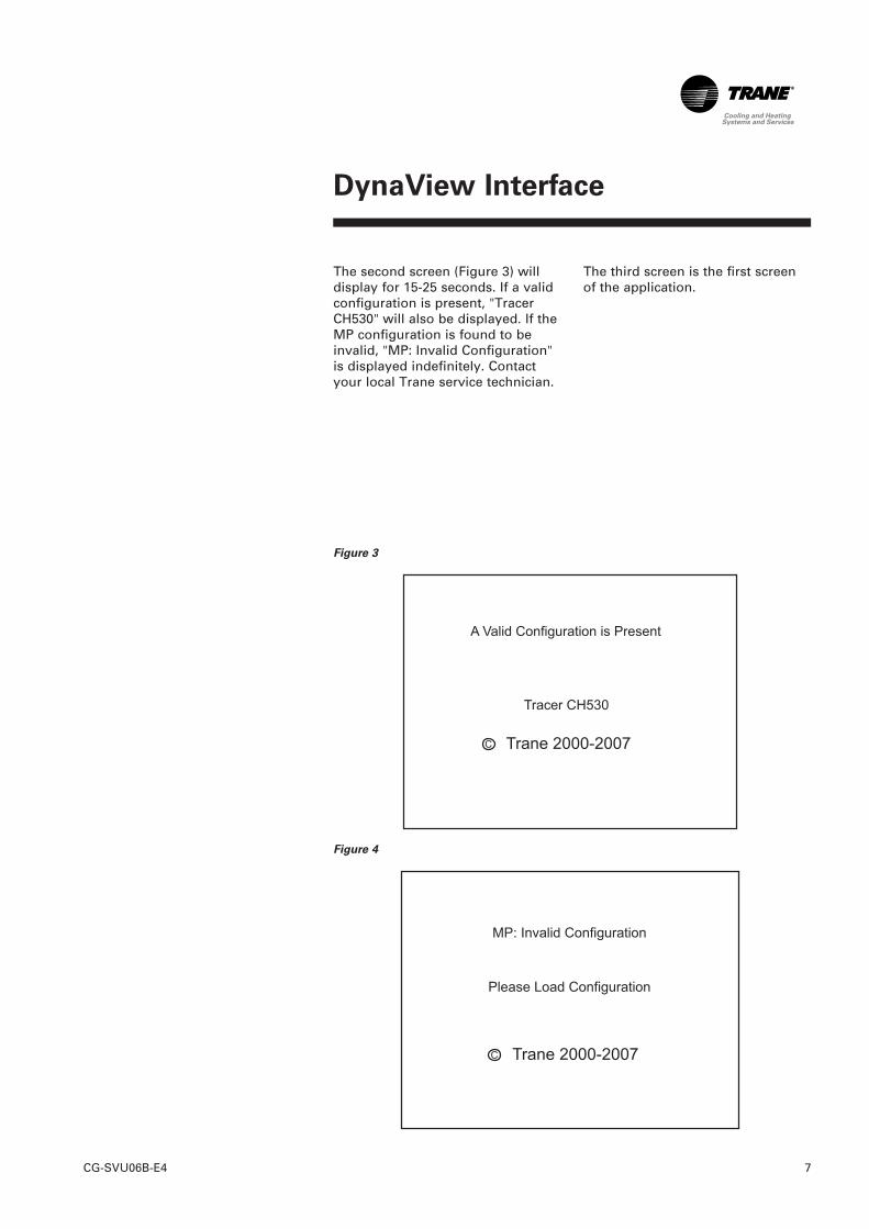
The second screen (Figure 3) willdisplay for 15-25 seconds. If a validconfiguration is present, "TracerCH530" will also be displayed. If theMP configuration is found to beinvalid, "MP: Invalid Configuration"is displayed indefinitely. Contactyour local Trane service technician.
Figure 3
Figure 4
The third screen is the first screenof the application.
DynaView Interface
CG-SVU06B-E48
The display on DynaView is a1/4 VGA display with a resistivetouch screen and an LED backlight.The display area is approximately4 inches wide by 3 inches high(102mm x 60mm).
CAUTION!
Equipment Damage! Putting
excessive pressure on the touch
screen could cause damage. It takes
less than 7 kg of force to break the
screen.
In this touch screen application, keyfunctions are determinedcompletely by software and changedepending upon the subject mattercurrently being displayed. The basictouch screen functions are outlinedbelow.
Radio Buttons
Radio buttons show 1 menu choiceamong 2 or more alternatives, allvisible. The possible selections areeach associated with a button. Theselected button is darkened,presented in reverse video toindicate it is the selected choice.The full range of possible choicesas well as the current choice isalways in view.
Spin Value Buttons
Spin values are used to allow avariable setpoint to be changed,such as leaving water setpoint. Thevalue increases or decreases bytouching the (+) or (-) arrows.
Action Buttons
Action buttons appear temporarilyand provide the user with a choicesuch as Enter or Cancel.
File Folder Tabs
File folder tabs are used to select ascreen of data. The tabs are in1 row across the top of the display.The user selects a screen ofinformation by touching theappropriate tab.
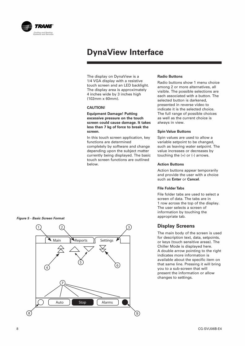
Display Screens
The main body of the screen is usedfor description text, data, setpoints,or keys (touch sensitive areas). TheChiller Mode is displayed here.A double arrow pointing to the rightindicates more information isavailable about the specific item onthat same line. Pressing it will bringyou to a sub-screen that willpresent the information or allowchanges to settings.
Figure 5 - Basic Screen Format
9
DynaView Interface
9CG-SVU06B-E4
The bottom of the screen (7) ispresent in all screens and containsthe following functions. Thecontrast (8,9) may require re-adjustment at ambienttemperatures significantly differentfrom those present at lastadjustment. The other functions arecritical to machine operation. TheAUTO and STOP keys are used toenable or disable the chiller. Thekey selected is in black (reversevideo). The chiller will stop whenthe STOP key is touched and aftercompleting the Run Unload mode.
Touching the AUTO key will enablethe chiller if no diagnostic ispresent. (A separate action must betaken to clear active diagnostics.)The AUTO and STOP keys takeprecedence over the Enter andCancel keys. (While a setting isbeing changed, AUTO and STOPkeys are recognized even if Enter orCancel has not been pressed.) TheALARMS button appears only whenan alarm is present, and blinks (byalternating between normal andreverse video) to draw attention toa diagnostic condition. Pressing theALARMS button takes you to thecorresponding tab for additionalinformation.
Note: screens may differ accordingto unit type or configuration. Theyshould be considered as examples.
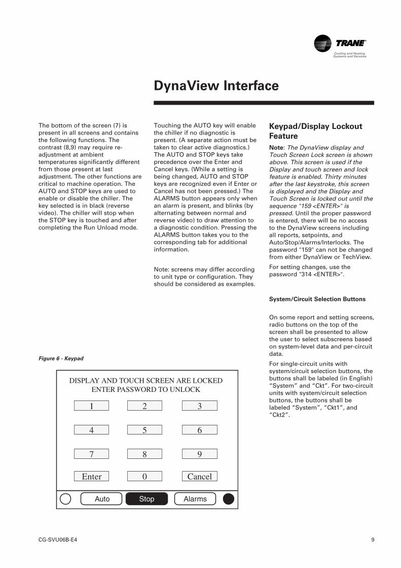
Keypad/Display Lockout
Feature
Note: The DynaView display andTouch Screen Lock screen is shownabove. This screen is used if theDisplay and touch screen and lockfeature is enabled. Thirty minutesafter the last keystroke, this screenis displayed and the Display andTouch Screen is locked out until thesequence "159 <ENTER>" ispressed. Until the proper passwordis entered, there will be no accessto the DynaView screens includingall reports, setpoints, andAuto/Stop/Alarms/Interlocks. Thepassword "159" can not be changedfrom either DynaView or TechView.
For setting changes, use thepassword "314 <ENTER>".
System/Circuit Selection Buttons
On some report and setting screens,radio buttons on the top of thescreen shall be presented to allowthe user to select subscreens basedon system-level data and per-circuitdata.
For single-circuit units withsystem/circuit selection buttons, thebuttons shall be labeled (in English)“System” and “Ckt”. For two-circuitunits with system/circuit selectionbuttons, the buttons shall belabeled “System”, “Ckt1”, and“Ckt2”.
Figure 6 - Keypad
1
DynaView Interface
CG-SVU06B-E410
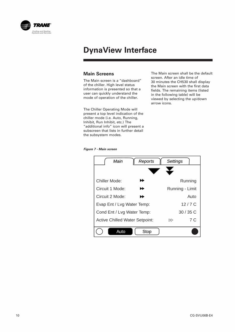
Main Screens
The Main screen is a “dashboard”of the chiller. High level statusinformation is presented so that auser can quickly understand themode of operation of the chiller.
The Chiller Operating Mode willpresent a top level indication of thechiller mode (i.e. Auto, Running,Inhibit, Run Inhibit, etc.) The“additional info” icon will present asubscreen that lists in further detailthe subsystem modes.
Figure 7 - Main screen
MainMain ReportsReports SettingsSettings
AutoAuto StopStop
Chiller Mode:
Circuit 1 Mode:
Circuit 2 Mode:
Evap Ent / Lvg Water Temp:
Cond Ent / Lvg Water Temp:
Active Chilled Water Setpoint:
Running
Running - Limit
Auto
12 / 7 C
30 / 35 C
7 C
The Main screen shall be the defaultscreen. After an idle time of30 minutes the CH530 shall displaythe Main screen with the first datafields. The remaining items (listedin the following table) will beviewed by selecting the up/downarrow icons.
DynaView Interface
11CG-SVU06B-E4
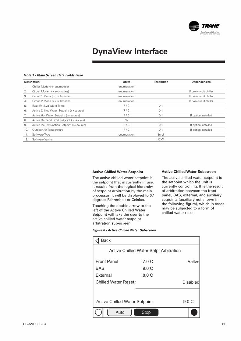
Table 1 - Main Screen Data Fields Table
Description Units Resolution Dependencies
1. Chiller Mode (>> submodes) enumeration
2. Circuit Mode (>> submodes) enumeration If one circuit chiller
3. Circuit 1 Mode (>> submodes) enumeration If two circuit chiller
4. Circuit 2 Mode (>> submodes) enumeration If two circuit chiller
5. Evap Ent/Lvg Water Temp F / C 0.1
6. Active Chilled Water Setpoint (>>source) F / C 0.1
7. Active Hot Water Setpoint (>>source) F / C 0.1 If option installed
8. Active Demand Limit Setpoint (>>source) % 1
9. Active Ice Termination Setpoint (>>source) F / C 0.1 If option installed
10. Outdoor Air Temperature F / C 0.1 If option installed
11. Software Type enumeration Scroll
12. Software Version X.XX
Figure 8 - Active Chilled Water Subscreen
:
Active Chilled Water Subscreen
The active chilled water setpoint isthe setpoint which the unit iscurrently controlling. It is the resultof arbitration between the frontpanel, BAS, external, and auxiliarysetpoints (auxiliary not shown inthe following figure), which in casesmay be subjected to a form ofchilled water reset.
Active Chilled Water Setpoint
The active chilled water setpoint isthe setpoint that is currently in use.It results from the logical hierarchyof setpoint arbitration by the mainprocessor. It will be displayed to 0.1degrees Fahrenheit or Celsius.
Touching the double arrow to theleft of the Active Chilled WaterSetpoint will take the user to theactive chilled water setpointarbitration sub-screen.
DynaView Interface
CG-SVU06B-E412
The chilled water reset status areain the most right column willdisplay one of the followingmessages• Return• Constant Return• Outdoor• Disabled
The left column text "Front Panel","BAS", "External", "Auxiliary","Chilled Water Reset", and "ActiveChilled Water Setpoint" will alwaysbe present regardless of installationor enabling those optional items. Inthe second column, "-----" will beshown if that option is Not Installed.Otherwise the current setpoint fromthat source will be shown.
Setpoints that are adjustable fromthe DynaView (Front Panel chilledwater setpoint, Auxiliary chilledwater setpoint) will providenavigation to their respectivesetpoint change screen via adouble-arrow to the right of thesetpoint source text. The setpointchange screen will look identical tothe one provided in the ChillerSetpoints screen. The "Back" buttonon the setpoint change screenprovides navigation back to thesetpoint arbitration screen.
The "Back" button on the setpointarbitration screen providesnavigation back to the chillerscreen.
Other Active Setpoints
The Active Hot Water Setpoint willbehave the same way as the ActiveChilled Water Setpoint.
The Active Demand Limit Setpointwill behave the same way as theActive Chilled Water Setpoint,except that its units are %.
The Active Ice Termination Setpointwill behave the same way as theActive Chilled Water Setpoint, withthe exception that Ice Terminationdoes not have an external orauxiliary source.
DynaView Interface
13CG-SVU06B-E4
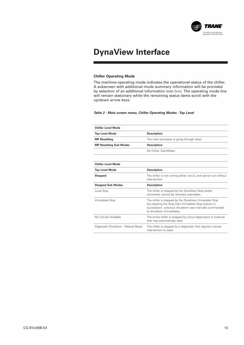
Chiller Operating Mode
The machine-operating mode indicates the operational status of the chiller.A subscreen with additional mode summary information will be providedby selection of an additional information icon (>>). The operating mode linewill remain stationary while the remaining status items scroll with theup/down arrow keys.
Table 2 - Main screen menu, Chiller Operating Modes - Top Level
Chiller Level Mode
Top Level Mode Description
MP Resetting The main processor is going through reset.
MP Resetting Sub Modes Description
No Chiller Sub-Modes
Chiller Level Mode
Top Level Mode Description
Stopped The chiller is not running either circuit, and cannot run withoutintervention.
Stopped Sub Modes Description
Local Stop The chiller is stopped by the DynaView Stop buttoncommand- cannot be remotely overridden.
Immediate Stop The chiller is stopped by the DynaView Immediate Stop(by pressing the Stop then Immediate Stop buttons insuccession) - previous shutdown was manually commandedto shutdown immediately.
No Circuits Available The entire chiller is stopped by circuit diagnostics or lockoutsthat may automatically clear.
Diagnostic Shutdown - Manual Reset The chiller is stopped by a diagnostic that requires manualintervention to reset.
DynaView Interface
CG-SVU06B-E414
Chiller Level Mode
Top Level Mode Description
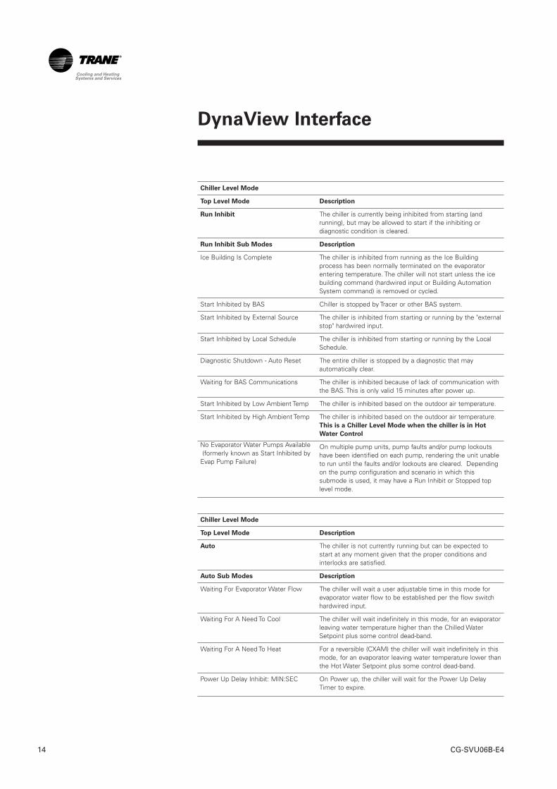
Run Inhibit The chiller is currently being inhibited from starting (andrunning), but may be allowed to start if the inhibiting ordiagnostic condition is cleared.
Run Inhibit Sub Modes Description
Ice Building Is Complete The chiller is inhibited from running as the Ice Buildingprocess has been normally terminated on the evaporatorentering temperature. The chiller will not start unless the icebuilding command (hardwired input or Building AutomationSystem command) is removed or cycled.
Start Inhibited by BAS Chiller is stopped by Tracer or other BAS system.
Start Inhibited by External Source The chiller is inhibited from starting or running by the "externalstop" hardwired input.
Start Inhibited by Local Schedule The chiller is inhibited from starting or running by the LocalSchedule.
Diagnostic Shutdown - Auto Reset The entire chiller is stopped by a diagnostic that mayautomatically clear.
Waiting for BAS Communications The chiller is inhibited because of lack of communication withthe BAS. This is only valid 15 minutes after power up.
Start Inhibited by Low Ambient Temp The chiller is inhibited based on the outdoor air temperature.
Start Inhibited by High Ambient Temp The chiller is inhibited based on the outdoor air temperature.This is a Chiller Level Mode when the chiller is in Hot
Water Control
On multiple pump units, pump faults and/or pump lockoutshave been identified on each pump, rendering the unit unableto run until the faults and/or lockouts are cleared. Dependingon the pump configuration and scenario in which thissubmode is used, it may have a Run Inhibit or Stopped toplevel mode.
Chiller Level Mode
Top Level Mode Description
Auto The chiller is not currently running but can be expected tostart at any moment given that the proper conditions andinterlocks are satisfied.
Auto Sub Modes Description
Waiting For Evaporator Water Flow The chiller will wait a user adjustable time in this mode forevaporator water flow to be established per the flow switchhardwired input.
Waiting For A Need To Cool The chiller will wait indefinitely in this mode, for an evaporatorleaving water temperature higher than the Chilled WaterSetpoint plus some control dead-band.
Waiting For A Need To Heat For a reversible (CXAM) the chiller will wait indefinitely in thismode, for an evaporator leaving water temperature lower thanthe Hot Water Setpoint plus some control dead-band.
Power Up Delay Inhibit: MIN:SEC On Power up, the chiller will wait for the Power Up DelayTimer to expire.
No Evaporator Water Pumps Available(formerly known as Start Inhibited by
Evap Pump Failure)
DynaView Interface
15CG-SVU06B-E4
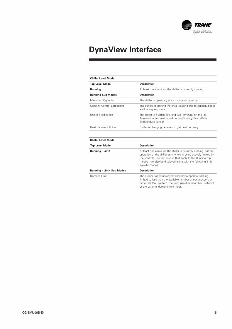
Chiller Level Mode
Top Level Mode Description
Running At least one circuit on the chiller is currently running.
Running Sub Modes Description
Maximum Capacity The chiller is operating at its maximum capacity.
Capacity Control Softloading The control is limiting the chiller loading due to capacity basedsoftloading setpoints.
Unit is Building Ice The chiller is Building Ice, and will terminate on the IceTermination Setpoint based on the Entering Evap WaterTemperature sensor.
Heat Recovery Active Chiller is changing behavior to get heat recovery..
Chiller Level Mode
Top Level Mode Description
Running - Limit At least one circuit on the chiller is currently running, but theoperation of the chiller as a whole is being actively limited bythe controls. The sub modes that apply to the Running topmodes may also be displayed along with the following limitspecific modes.
Running - Limit Sub Modes Description
Demand Limit The number of compressors allowed to operate is beinglimited to less than the available number of compressors byeither the BAS system, the front panel demand limit setpointor the external demand limit input.
DynaView Interface
CG-SVU06B-E416
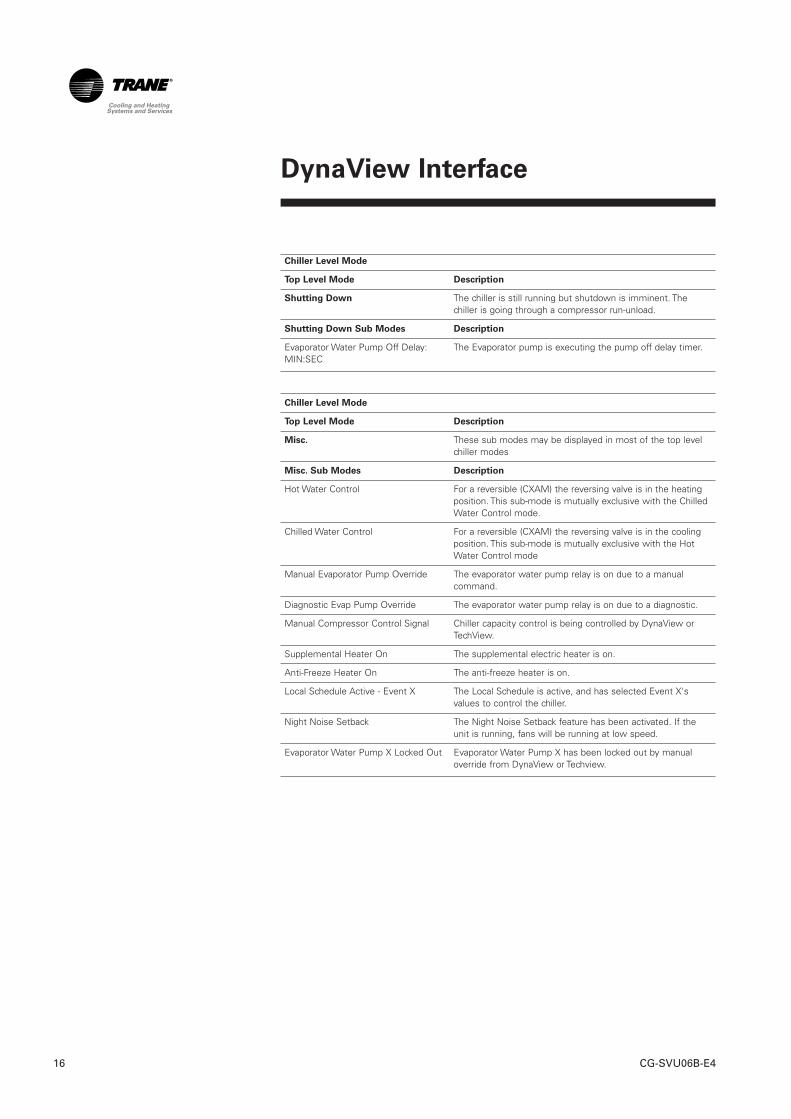
Chiller Level Mode
Top Level Mode Description
Shutting Down The chiller is still running but shutdown is imminent. Thechiller is going through a compressor run-unload.
Shutting Down Sub Modes Description
The Evaporator pump is executing the pump off delay timer.
Chiller Level Mode
Top Level Mode Description
Misc. These sub modes may be displayed in most of the top levelchiller modes
Misc. Sub Modes Description
Hot Water Control For a reversible (CXAM) the reversing valve is in the heatingposition. This sub-mode is mutually exclusive with the ChilledWater Control mode.
Chilled Water Control For a reversible (CXAM) the reversing valve is in the coolingposition. This sub-mode is mutually exclusive with the HotWater Control mode
Manual Evaporator Pump Override The evaporator water pump relay is on due to a manualcommand.
Diagnostic Evap Pump Override The evaporator water pump relay is on due to a diagnostic.
Manual Compressor Control Signal Chiller capacity control is being controlled by DynaView orTechView.
Supplemental Heater On The supplemental electric heater is on.
Anti-Freeze Heater On The anti-freeze heater is on.
Local Schedule Active - Event X The Local Schedule is active, and has selected Event X'svalues to control the chiller.
Night Noise Setback The Night Noise Setback feature has been activated. If theunit is running, fans will be running at low speed.
Evaporator Water Pump X Locked Out Evaporator Water Pump X has been locked out by manualoverride from DynaView or Techview.
Evaporator Water Pump Off Delay:MIN:SEC
DynaView Interface
17CG-SVU06B-E4
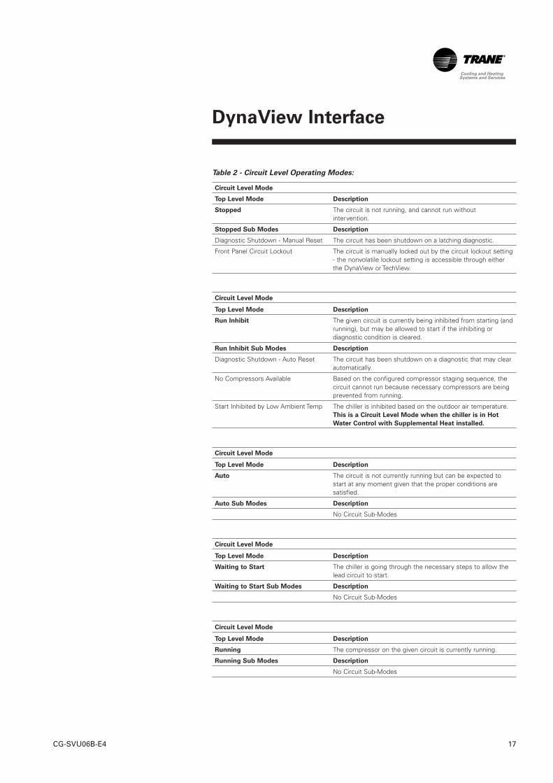
Table 2 - Circuit Level Operating Modes:
Circuit Level Mode
Top Level Mode Description
Stopped The circuit is not running, and cannot run withoutintervention.
Stopped Sub Modes Description
Diagnostic Shutdown - Manual Reset The circuit has been shutdown on a latching diagnostic.
Front Panel Circuit Lockout The circuit is manually locked out by the circuit lockout setting- the nonvolatile lockout setting is accessible through eitherthe DynaView or TechView.
Circuit Level Mode
Top Level Mode Description
Run Inhibit The given circuit is currently being inhibited from starting (andrunning), but may be allowed to start if the inhibiting ordiagnostic condition is cleared.
Run Inhibit Sub Modes Description
Diagnostic Shutdown - Auto Reset The circuit has been shutdown on a diagnostic that may clearautomatically.
No Compressors Available Based on the configured compressor staging sequence, thecircuit cannot run because necessary compressors are beingprevented from running.
Start Inhibited by Low Ambient Temp The chiller is inhibited based on the outdoor air temperature.This is a Circuit Level Mode when the chiller is in Hot
Water Control with Supplemental Heat installed.
Circuit Level Mode
Top Level Mode Description
Auto The circuit is not currently running but can be expected tostart at any moment given that the proper conditions aresatisfied.
Auto Sub Modes Description
No Circuit Sub-Modes
Circuit Level Mode
Top Level Mode Description
Waiting to Start The chiller is going through the necessary steps to allow thelead circuit to start.
Waiting to Start Sub Modes Description
No Circuit Sub-Modes
Circuit Level Mode
Top Level Mode Description
Running The compressor on the given circuit is currently running.
Running Sub Modes Description
No Circuit Sub-Modes
DynaView Interface
CG-SVU06B-E418
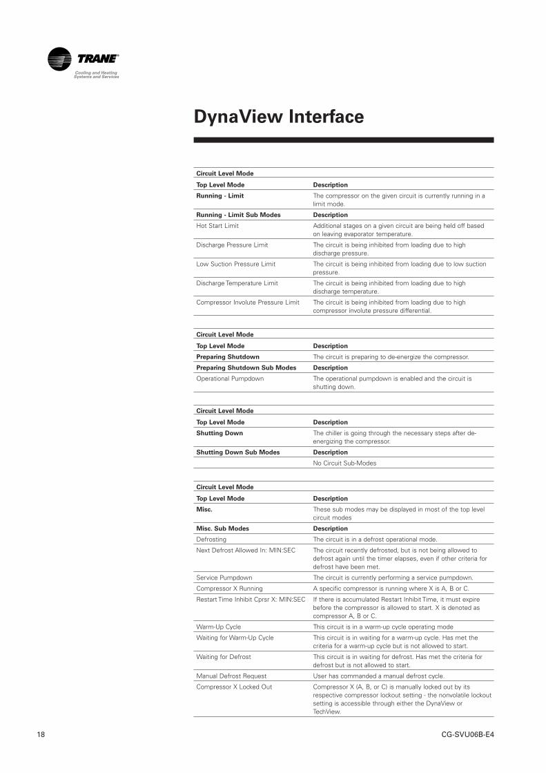
Circuit Level Mode
Top Level Mode Description
Running - Limit The compressor on the given circuit is currently running in alimit mode.
Running - Limit Sub Modes Description
Hot Start Limit Additional stages on a given circuit are being held off basedon leaving evaporator temperature.
Discharge Pressure Limit The circuit is being inhibited from loading due to highdischarge pressure.
Low Suction Pressure Limit The circuit is being inhibited from loading due to low suctionpressure.
Discharge Temperature Limit The circuit is being inhibited from loading due to highdischarge temperature.
Compressor Involute Pressure Limit The circuit is being inhibited from loading due to highcompressor involute pressure differential.
Circuit Level Mode
Top Level Mode Description
Preparing Shutdown The circuit is preparing to de-energize the compressor.
Preparing Shutdown Sub Modes Description
Operational Pumpdown The operational pumpdown is enabled and the circuit isshutting down.
Circuit Level Mode
Top Level Mode Description
Shutting Down The chiller is going through the necessary steps after de-energizing the compressor.
Shutting Down Sub Modes Description
No Circuit Sub-Modes
Circuit Level Mode
Top Level Mode Description
Misc. These sub modes may be displayed in most of the top levelcircuit modes
Misc. Sub Modes Description
Defrosting The circuit is in a defrost operational mode.
Next Defrost Allowed In: MIN:SEC The circuit recently defrosted, but is not being allowed todefrost again until the timer elapses, even if other criteria fordefrost have been met.
Service Pumpdown The circuit is currently performing a service pumpdown.
Compressor X Running A specific compressor is running where X is A, B or C.
Restart Time Inhibit Cprsr X: MIN:SEC If there is accumulated Restart Inhibit Time, it must expirebefore the compressor is allowed to start. X is denoted ascompressor A, B or C.
Warm-Up Cycle This circuit is in a warm-up cycle operating mode
Waiting for Warm-Up Cycle This circuit is in waiting for a warm-up cycle. Has met thecriteria for a warm-up cycle but is not allowed to start.
Waiting for Defrost This circuit is in waiting for defrost. Has met the criteria fordefrost but is not allowed to start.
Manual Defrost Request User has commanded a manual defrost cycle.
Compressor X Locked Out Compressor X (A, B, or C) is manually locked out by itsrespective compressor lockout setting - the nonvolatile lockoutsetting is accessible through either the DynaView orTechView.
DynaView Interface
19CG-SVU06B-E4
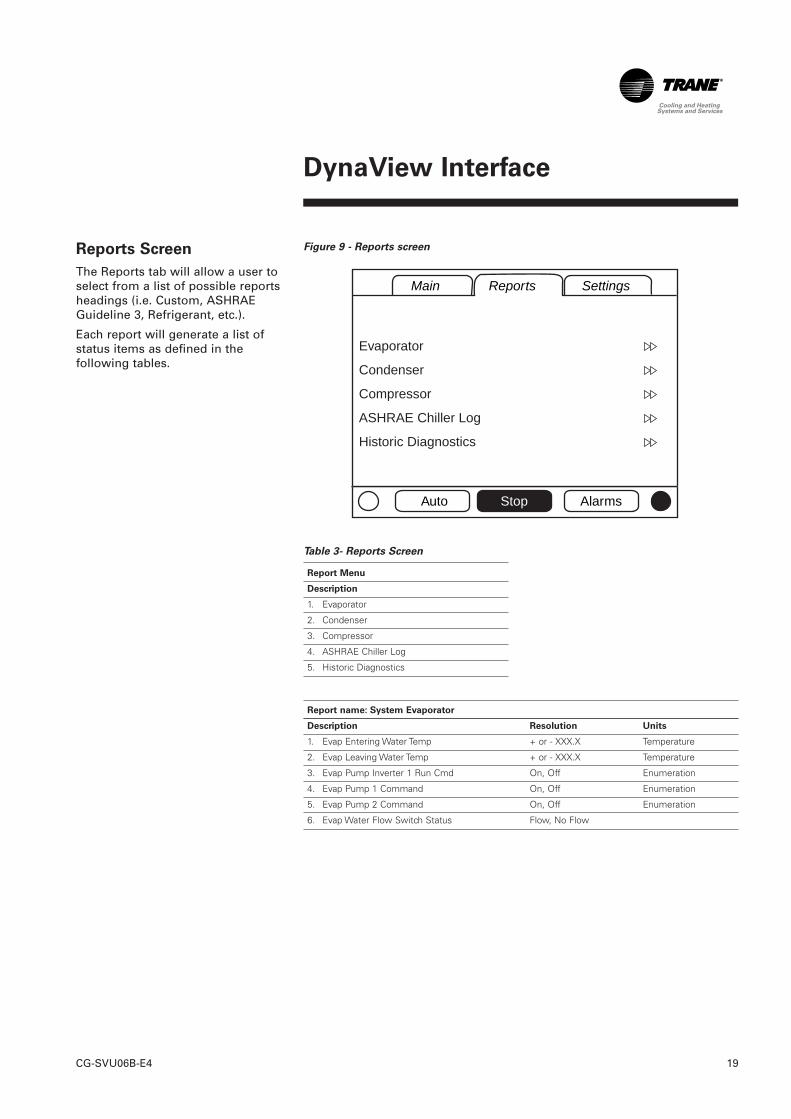
Reports Screen
The Reports tab will allow a user toselect from a list of possible reportsheadings (i.e. Custom, ASHRAEGuideline 3, Refrigerant, etc.).
Each report will generate a list ofstatus items as defined in thefollowing tables.
Figure 9 - Reports screen
Table 3- Reports Screen
Report Menu
Description
1. Evaporator
2. Condenser
3. Compressor
4. ASHRAE Chiller Log
5. Historic Diagnostics
Report name: System Evaporator
Description Resolution Units
1. Evap Entering Water Temp + or - XXX.X Temperature
2. Evap Leaving Water Temp + or - XXX.X Temperature
3. Evap Pump Inverter 1 Run Cmd On, Off Enumeration
4. Evap Pump 1 Command On, Off Enumeration
5. Evap Pump 2 Command On, Off Enumeration
6. Evap Water Flow Switch Status Flow, No Flow
Main Reports Settings
Auto Stop Alarms
Evaporator
Condenser
Compressor
ASHRAE Chiller Log
Historic Diagnostics
DynaView Interface
CG-SVU06B-E420
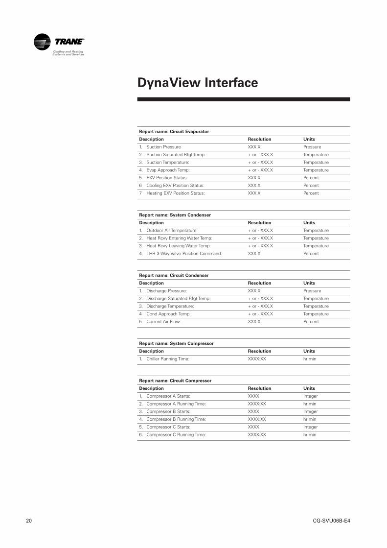
Report name: Circuit Evaporator
Description Resolution Units
1. Suction Pressure XXX.X Pressure
2. Suction Saturated Rfgt Temp: + or - XXX.X Temperature
3. Suction Temperature: + or - XXX.X Temperature
4. Evap Approach Temp: + or - XXX.X Temperature
5 EXV Position Status: XXX.X Percent
6 Cooling EXV Position Status: XXX.X Percent
7 Heating EXV Position Status: XXX.X Percent
Report name: System Condenser
Description Resolution Units
1. Outdoor Air Temperature: + or - XXX.X Temperature
2. Heat Rcvy Entering Water Temp: + or - XXX.X Temperature
3. Heat Rcvy Leaving Water Temp: + or - XXX.X Temperature
4. THR 3-Way Valve Position Command: XXX.X Percent
Report name: Circuit Condenser
Description Resolution Units
1. Discharge Pressure: XXX.X Pressure
2. Discharge Saturated Rfgt Temp: + or - XXX.X Temperature
3. Discharge Temperature: + or - XXX.X Temperature
4 Cond Approach Temp: + or - XXX.X Temperature
5 Current Air Flow: XXX.X Percent
Report name: System Compressor
Description Resolution Units
1. Chiller Running Time: XXXX:XX hr:min
Report name: Circuit Compressor
Description Resolution Units
1. Compressor A Starts: XXXX Integer
2. Compressor A Running Time: XXXX:XX hr:min
3. Compressor B Starts: XXXX Integer
4. Compressor B Running Time: XXXX:XX hr:min
5. Compressor C Starts: XXXX Integer
6. Compressor C Running Time: XXXX:XX hr:min
DynaView Interface
21CG-SVU06B-E4
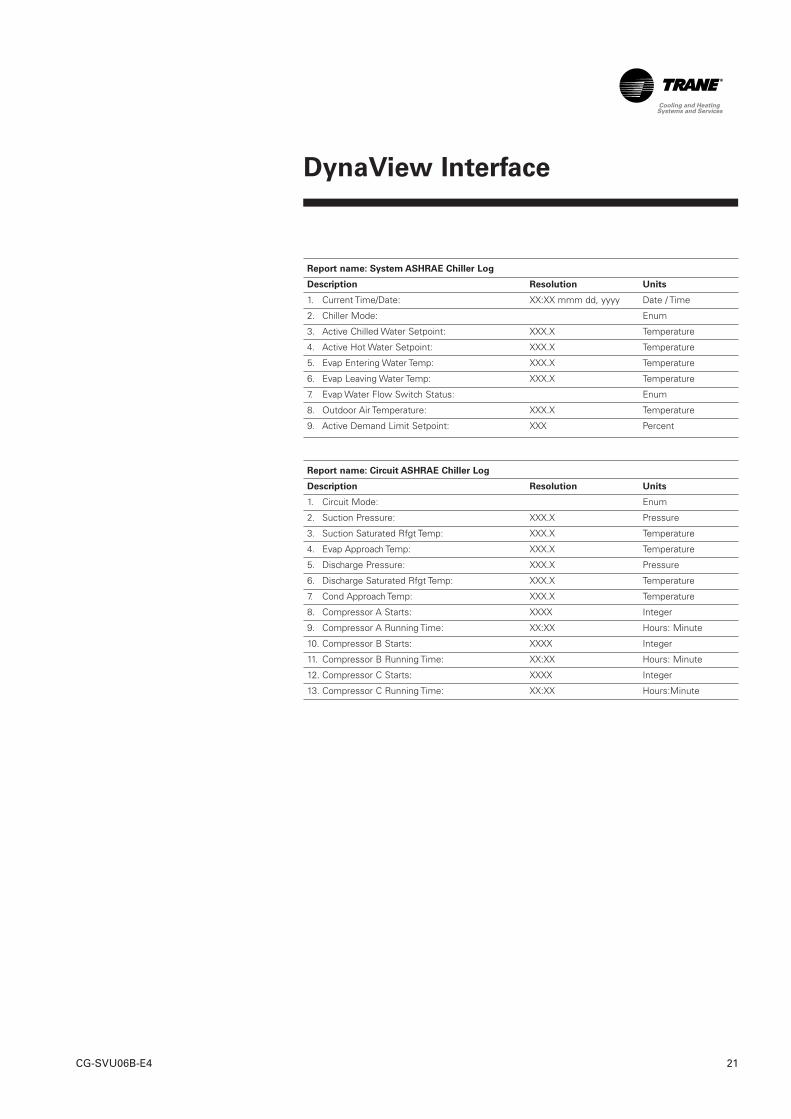
Report name: System ASHRAE Chiller Log
Description Resolution Units
1. Current Time/Date: XX:XX mmm dd, yyyy Date / Time
2. Chiller Mode: Enum
3. Active Chilled Water Setpoint: XXX.X Temperature
4. Active Hot Water Setpoint: XXX.X Temperature
5. Evap Entering Water Temp: XXX.X Temperature
6. Evap Leaving Water Temp: XXX.X Temperature
7. Evap Water Flow Switch Status: Enum
8. Outdoor Air Temperature: XXX.X Temperature
9. Active Demand Limit Setpoint: XXX Percent
Report name: Circuit ASHRAE Chiller Log
Description Resolution Units
1. Circuit Mode: Enum
2. Suction Pressure: XXX.X Pressure
3. Suction Saturated Rfgt Temp: XXX.X Temperature
4. Evap Approach Temp: XXX.X Temperature
5. Discharge Pressure: XXX.X Pressure
6. Discharge Saturated Rfgt Temp: XXX.X Temperature
7. Cond Approach Temp: XXX.X Temperature
8. Compressor A Starts: XXXX Integer
9. Compressor A Running Time: XX:XX Hours: Minute
10. Compressor B Starts: XXXX Integer
11. Compressor B Running Time: XX:XX Hours: Minute
12. Compressor C Starts: XXXX Integer
13. Compressor C Running Time: XX:XX Hours:Minute
DynaView Interface
CG-SVU06B-E422
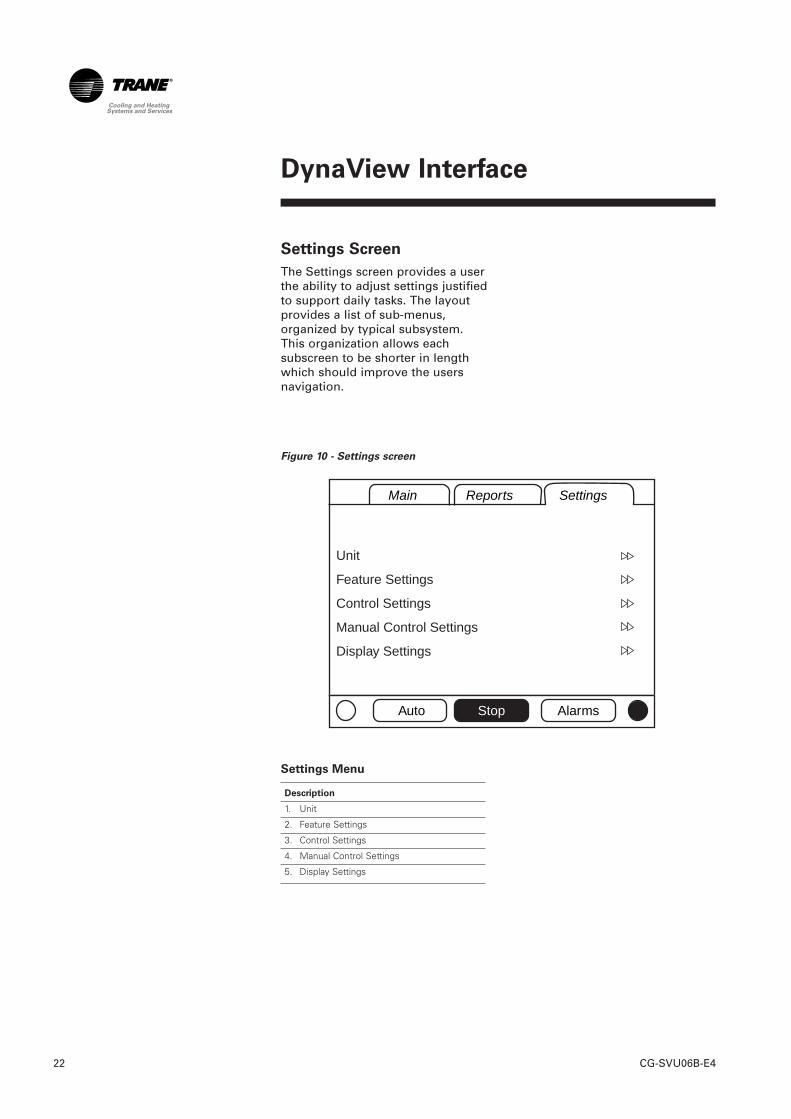
Settings Screen
The Settings screen provides a userthe ability to adjust settings justifiedto support daily tasks. The layoutprovides a list of sub-menus,organized by typical subsystem.This organization allows eachsubscreen to be shorter in lengthwhich should improve the usersnavigation.
Figure 10 - Settings screen
Settings Menu
Description
1. Unit
2. Feature Settings
3. Control Settings
4. Manual Control Settings
5. Display Settings
Main Reports Settings
Auto Stop Alarms
Unit
Feature Settings
Control Settings
Manual Control Settings
Display Settings
DynaView Interface
23CG-SVU06B-E4
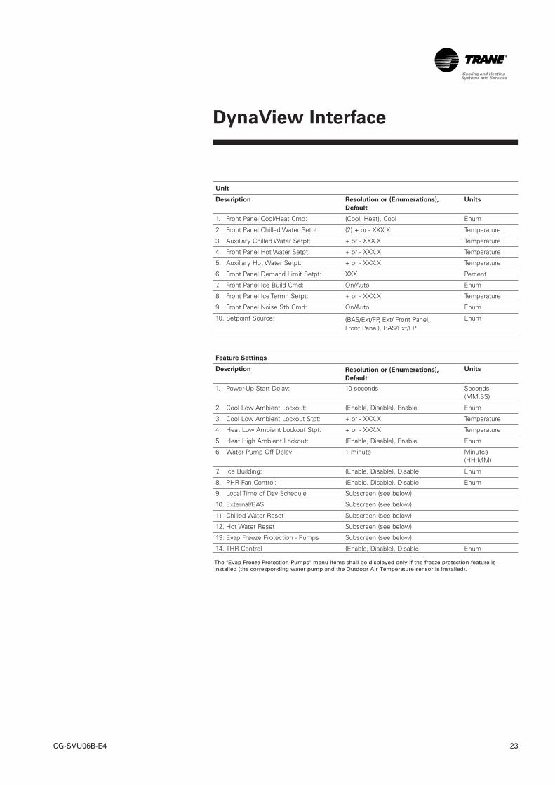
Unit
Description Units
1. Front Panel Cool/Heat Cmd: (Cool, Heat), Cool Enum
2. Front Panel Chilled Water Setpt: (2) + or - XXX.X Temperature
3. Auxiliary Chilled Water Setpt: + or - XXX.X Temperature
4. Front Panel Hot Water Setpt: + or - XXX.X Temperature
5. Auxiliary Hot Water Setpt: + or - XXX.X Temperature
6. Front Panel Demand Limit Setpt: XXX Percent
7. Front Panel Ice Build Cmd: On/Auto Enum
8. Front Panel Ice Termn Setpt: + or - XXX.X Temperature
9. Front Panel Noise Stb Cmd: On/Auto Enum
10. Setpoint Source: Enum
Feature Settings
Description Units
1. Power-Up Start Delay: 10 seconds Seconds (MM:SS)
2. Cool Low Ambient Lockout: (Enable, Disable), Enable Enum
3. Cool Low Ambient Lockout Stpt: + or - XXX.X Temperature
4. Heat Low Ambient Lockout Stpt: + or - XXX.X Temperature
5. Heat High Ambient Lockout: (Enable, Disable), Enable Enum
6. Water Pump Off Delay: 1 minute Minutes (HH:MM)
7. Ice Building: (Enable, Disable), Disable Enum
8. PHR Fan Control: (Enable, Disable), Disable Enum
9. Local Time of Day Schedule Subscreen (see below)
10. External/BAS Subscreen (see below)
11. Chilled Water Reset Subscreen (see below)
12. Hot Water Reset Subscreen (see below)
13. Evap Freeze Protection - Pumps Subscreen (see below)
14. THR Control (Enable, Disable), Disable Enum
The "Evap Freeze Protection-Pumps" menu items shall be displayed only if the freeze protection feature isinstalled (the corresponding water pump and the Outdoor Air Temperature sensor is installed).
Resolution or (Enumerations),
Default
Resolution or (Enumerations),
Default
(BAS/Ext/FP, Ext/ Front Panel,Front Panel), BAS/Ext/FP
DynaView Interface
CG-SVU06B-E424
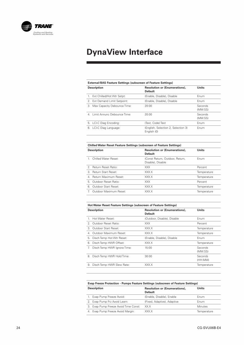
External/BAS Feature Settings (subscreen of Feature Settings)
Description Units
1. Ext Chilled/Hot Wtr Setpt: (Enable, Disable), Disable Enum
2. Ext Demand Limit Setpoint: (Enable, Disable), Disable Enum
3. Max Capacity Debounce Time: 20:00 Seconds (MM:SS)
4. Limit Annunc Debounce Time: 20:00 Seconds (MM:SS)
5. LCI-C Diag Encoding: (Text, Code) Text Enum
6. LCI-C Diag Language: Enum
Chilled Water Reset Feature Settings (subscreen of Feature Settings)
Description Units
1. Chilled Water Reset: Enum
2. Return Reset Ratio: XXX Percent
3. Return Start Reset: XXX.X Temperature
4. Return Maximum Reset: XXX.X Temperature
5. Outdoor Reset Ratio: XXX Percent
6. Outdoor Start Reset: XXX.X Temperature
7. Outdoor Maximum Reset: XXX.X Temperature
Hot Water Reset Feature Settings (subscreen of Feature Settings)
Description Units
1. Hot Water Reset: (Outdoor, Disable), Disable Enum
2. Outdoor Reset Ratio: XXX Percent
3. Outdoor Start Reset: XXX.X Temperature
4. Outdoor Maximum Reset: XXX.X Temperature
5. Disch Temp Hot Wtr Reset: (Enable, Disable), Disable Enum
6. Disch Temp HWR Offset: XXX.X Temperature
7. Disch Temp HWR Ignore Time: 15:00 Seconds (MM:SS)
8. Disch Temp HWR Hold Time: 30:00 Seconds (HH:MM)
9. Disch Temp HWR Slew Rate: XXX.X Temperature
Evap Freeze Protection - Pumps Feature Settings (subscreen of Feature Settings)
Description Units
1. Evap Pump Freeze Avoid: (Enable, Disable), Enable Enum
2. Evap Pump Frz Avoid Learn: (Fixed, Adaptive), Adaptive Enum
3. Evap Pump Freeze Avoid Time Const: XX.X Minutes
4. Evap Pump Freeze Avoid Margin: XXX.X Temperature
Resolution or (Enumerations),
Default
(English, Selection 2, Selection 3)English (0)
Resolution or (Enumerations),
Default
Resolution or (Enumerations),
Default
Resolution or (Enumerations),
Default
(Const Return, Outdoor, Return,Disable), Disable
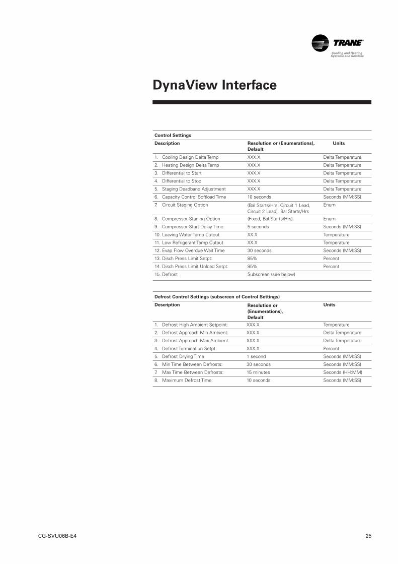
Control Settings
Description Units
1. Cooling Design Delta Temp XXX.X Delta Temperature
2. Heating Design Delta Temp XXX.X Delta Temperature
3. Differential to Start XXX.X Delta Temperature
4. Differential to Stop XXX.X Delta Temperature
5. Staging Deadband Adjustment XXX.X Delta Temperature
6. Capacity Control Softload Time 10 seconds Seconds (MM:SS)
7. Circuit Staging Option Enum
8. Compressor Staging Option (Fixed, Bal Starts/Hrs) Enum
9. Compressor Start Delay Time 5 seconds Seconds (MM:SS)
10. Leaving Water Temp Cutout XX.X Temperature
11. Low Refrigerant Temp Cutout XX.X Temperature
12. Evap Flow Overdue Wait Time 30 seconds Seconds (MM:SS)
13. Disch Press Limit Setpt: 85% Percent
14. Disch Press Limit Unload Setpt: 95% Percent
15. Defrost Subscreen (see below)
Defrost Control Settings (subscreen of Control Settings)
Description Units
1. Defrost High Ambient Setpoint: XXX.X Temperature
2. Defrost Approach Min Ambient: XXX.X Delta Temperature
3. Defrost Approach Max Ambient: XXX.X Delta Temperature
4. Defrost Termination Setpt: XXX.X Percent
5. Defrost Drying Time 1 second Seconds (MM:SS)
6. Min Time Between Defrosts: 30 seconds Seconds (MM:SS)
7. Max Time Between Defrosts: 15 minutes Seconds (HH:MM)
8. Maximum Defrost Time: 10 seconds Seconds (MM:SS)
DynaView Interface
25CG-SVU06B-E4
Resolution or (Enumerations),
Default
(Bal Starts/Hrs, Circuit 1 Lead,Circuit 2 Lead), Bal Starts/Hrs
Resolution or
(Enumerations),
Default
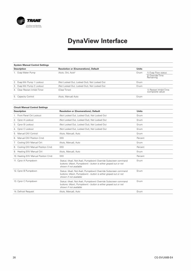
System Manual Control Settings
Description Resolution or (Enumerations), Default Units
1. Evap Water Pump (Auto, On), Auto6 Enum
2. Evap Wtr Pump 1 Lockout (Not Locked Out, Locked Out), Not Locked Out Enum
3. Evap Wtr Pump 2 Lockout (Not Locked Out, Locked Out), Not Locked Out Enum
4. Clear Restart Inhibit Timer (Clear Timer)
5. Capacity Control (Auto, Manual) Auto Enum
Circuit Manual Control Settings
Description Resolution or (Enumerations), Default Units
1. Front Panel Ckt Lockout (Not Locked Out, Locked Out), Not Locked Out Enum
2. Cprsr A Lockout (Not Locked Out, Locked Out), Not Locked Out Enum
3. Cprsr B Lockout (Not Locked Out, Locked Out), Not Locked Out Enum
4. Cprsr C Lockout (Not Locked Out, Locked Out), Not Locked Out Enum
5. Manual EXV Control: (Auto, Manual), Auto Enum
6. Manual EXV Position Cmd: XXX Percent
7. Cooling EXV Manual Ctrl: (Auto, Manual), Auto Enum
8. Cooling EXV Manual Position Cmd: XXX Percent
9. Heating EXV Manual Ctrl: (Auto, Manual), Auto Enum
10. Heating EXV Manual Position Cmd: XXX Percent
11. Cprsr A Pumpdown Enum
12. Cprsr B Pumpdown Enum
13. Cprsr C Pumpdown Enum
14. Defrost Request (Auto, Manual), Auto Enum
DynaView Interface
CG-SVU06B-E426
Status: (Avail, Not Avail, Pumpdown) Override Subscreen commandbuttons: (Abort, Pumpdown) - button is either grayed out or notshown if not available
Status: (Avail, Not Avail, Pumpdown) Override Subscreen commandbuttons: (Abort, Pumpdown) - button is either grayed out or notshown if not available
Status: (Avail, Not Avail, Pumpdown) Override Subscreen commandbuttons: (Abort, Pumpdown) - button is either grayed out or notshown if not available
1) Evap Flow status2) Override TimeRemaining
1) Restart Inhibit Time(composite value)
DynaView Interface
27CG-SVU06B-E4
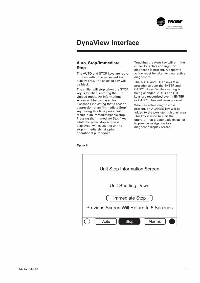
Auto, Stop/Immediate
Stop
The AUTO and STOP keys are radiobuttons within the persistent keydisplay area. The selected key willbe black.
The chiller will stop when the STOPkey is touched, entering the RunUnload mode. An informationalscreen will be displayed for5 seconds indicating that a seconddepression of an "Immediate Stop"key during this time period willresult in an immediate/panic stop.Pressing the "Immediate Stop" keywhile the panic stop screen isdisplayed, will cause the unit tostop immediately, skippingoperational pumpdown.
Touching the Auto key will arm thechiller for active cooling if nodiagnostic is present. A separateaction must be taken to clear activediagnostics.
The AUTO and STOP keys takeprecedence over the ENTER andCANCEL keys. While a setting isbeing changed, AUTO and STOPkeys are recognized even if ENTERor CANCEL has not been pressed.
When an active diagnostic ispresent, an ALARMS key will beadded to the persistent display area.This key is used to alert theoperator that a diagnostic exists, orto provide navigation to adiagnostic display screen.
Figure 11
Auto Stop Alarms
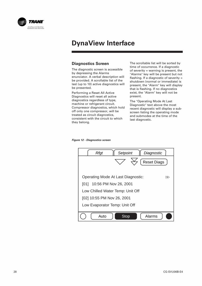
Diagnostics Screen
The diagnostic screen is accessibleby depressing the Alarmsenunciator. A verbal description willbe provided. A scrollable list of thelast (up to 10) active diagnostics willbe presented.
Performing a Reset All ActiveDiagnostics will reset all activediagnostics regardless of type,machine or refrigerant circuit.Compressor diagnostics, which holdoff only one compressor, will betreated as circuit diagnostics,consistent with the circuit to whichthey belong.
The scrollable list will be sorted bytime of occurrence. If a diagnosticof severity = warning is present, the"Alarms" key will be present but notflashing. If a diagnostic of severity =shutdown (normal or immediate) ispresent, the "Alarm" key will displaythat is flashing. If no diagnosticsexist, the "Alarm" key will not bepresent.
The "Operating Mode At LastDiagnostic" text above the mostrecent diagnostic will display a sub-screen listing the operating modeand submodes at the time of thelast diagnostic.
DynaView Interface
CG-SVU06B-E428
Figure 12 - Diagnostics screen
Rfgt Setpoint Diagnostic
Auto Stop Alarms
Reset Diags
Operating Mode At Last Diagnostic:
[01] 10:56 PM Nov 26, 2001
Low Chilled Water Temp: Unit Off
[02] 10:55 PM Nov 26, 2001
Low Evaporator Temp: Unit Off
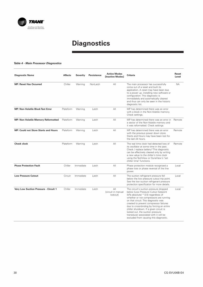
Diagnostics
29CG-SVU06B-E4
The following diagnostic tablecontains all the diagnosticspossible. Not all data is availableunless tech view is connected.
Code: Three digit hexadecimal codeused on all past products touniquely identify diagnostics.
Diagnostic Name: Name ofDiagnostic and its source. Note thatthis is the exact text used in theUser Interface and/or Service Tooldisplays.
Severity: Defines the severity of theabove effect. Immediate meansimmediate shutdown of the effectedportion, Normal means normal orfriendly shutdown of the effectedportion, Special Mode means aspecial mode of operation (limpalong) is invoked, but withoutshutdown, and Info means anInformational Note or Warning isgenerated.
Persistence: Defines whether or notthe diagnostic and its effects are tobe manually reset (Latched), or canbe either manually or automaticallyreset (Nonlatched).
Criteria: Quantitatively defines thecriteria used in generating thediagnostic and, if nonlatching, thecriteria for auto reset. If moreexplanation is necessary a hot linkto the Functional Specification isused.
Reset Level: Defines the lowest levelof manual diagnostic resetcommand which can clear thediagnostic. The manual diagnosticreset levels in order of priority are:Local and Remote. A diagnostic thathas a reset level of Local, can onlybe reset by a local diagnostic resetcommand, but not by the lowerpriority remote Reset commandwhereas a diagnostic listed asRemote reset can be reset by either.
Diagnostics
CG-SVU06B-E430
Diagnostic Name Affects Severity PersistenceActive Modes
[Inactive Modes]Criteria
Reset
Level
MP: Reset Has Occurred Chiller Warning NonLatch All The main processor has successfullycome out of a reset and built itsapplication. A reset may have been dueto a power up, installing new software orconfiguration. This diagnostic isimmediately and automatically clearedand thus can only be seen in the historicdiagnostic list.
NA
MP: Non-Volatile Block Test Error Plateform Warning Latch All MP has determined there was an errorwith a block in the Non-Volatile memory.Check settings.
MP: Non-Volatile Memory Reformatted Plateform Warning Latch All MP has determined there was an error ina sector of the Non-Volatile memory andit was reformatted. Check settings
Remote
MP: Could not Store Starts and Hours Plateform Warning Latch All MP has determined there was an errorwith the previous power down store.Starts and Hours may have been lost forthe last 24 hours.
Remote
Check clock Plateform Warning Latch All The real time clock had detected loss ofits oscillator at some time in the past.Check / replace battery? This diagnosticcan be effectively cleared only by writinga new value to the chiller's time clockusing the TechView or DynaView's "setchiller time" functions.
Remote
Phase Protection Fault Chiller Immediate Latch All Phase protection module recognized aphase loss or phase reversal of the linepower.
Local
Low Pressure Cutout Circuit Immediate Latch All The suction refrigerant pressure fellbelow the low pressure cutout trip point.See the low suction refrigerant pressureprotection specification for more details.
Local
Very Low Suction Pressure - Circuit 1 Chiller Immediate Latch All [circuit in manual
lockout]
The circuit's suction pressure droppedbelow (Low Pressure Cutout Setpoint(kPa absolute) * 0.5) regardless ofwhether or not compressors are runningon that circuit. This diagnostic wascreated to prevent compressor failuresdue to cross-binding by forcing an entirechiller shutdown. If a given circuit islocked out, the suction pressuretransducer associated with it will beexcluded from causing this diagnostic.
Local
Table 4 - Main Processor Diagnostics
Diagnostics
31CG-SVU06B-E4
Diagnostic Name Affects Severity PersistenceActive Modes
[Inactive Modes]Criteria
Reset
Level
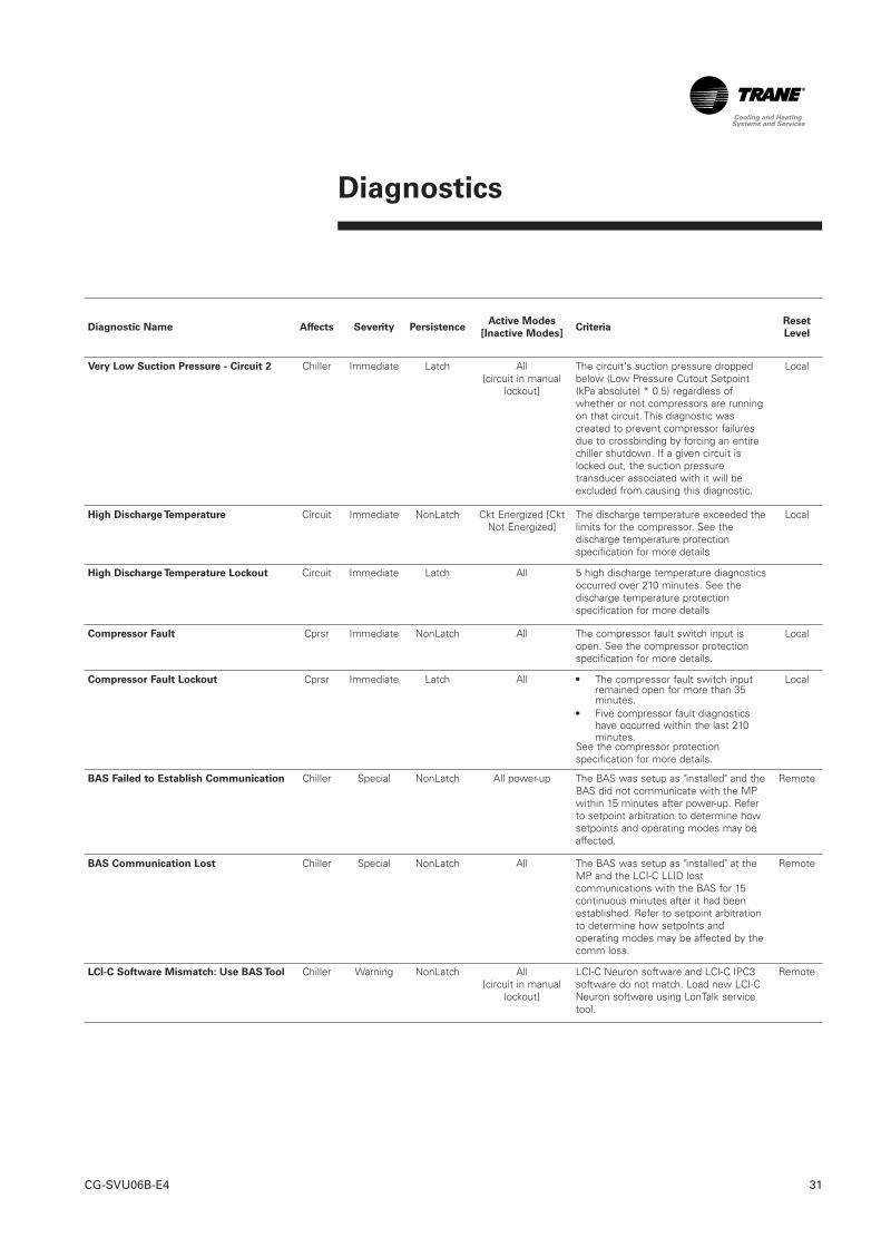
Very Low Suction Pressure - Circuit 2 Chiller Immediate Latch All [circuit in manual
lockout]
The circuit's suction pressure droppedbelow (Low Pressure Cutout Setpoint(kPa absolute) * 0.5) regardless ofwhether or not compressors are runningon that circuit. This diagnostic wascreated to prevent compressor failuresdue to crossbinding by forcing an entirechiller shutdown. If a given circuit islocked out, the suction pressuretransducer associated with it will beexcluded from causing this diagnostic.
Local
High Discharge Temperature Circuit Immediate NonLatch Ckt Energized [CktNot Energized]
The discharge temperature exceeded thelimits for the compressor. See thedischarge temperature protectionspecification for more details
Local
High Discharge Temperature Lockout Circuit Immediate Latch All 5 high discharge temperature diagnosticsoccurred over 210 minutes. See thedischarge temperature protectionspecification for more details
Compressor Fault Cprsr Immediate NonLatch All The compressor fault switch input isopen. See the compressor protectionspecification for more details.
Local
Compressor Fault Lockout Cprsr Immediate Latch All • The compressor fault switch inputremained open for more than 35minutes.
• Five compressor fault diagnosticshave occurred within the last 210minutes.
See the compressor protectionspecification for more details.
Local
BAS Failed to Establish Communication Chiller Special NonLatch All power-up The BAS was setup as "installed" and theBAS did not communicate with the MPwithin 15 minutes after power-up. Referto setpoint arbitration to determine howsetpoints and operating modes may beaffected.
Remote
BAS Communication Lost Chiller Special NonLatch All The BAS was setup as "installed" at theMP and the LCI-C LLID lostcommunications with the BAS for 15continuous minutes after it had beenestablished. Refer to setpoint arbitrationto determine how setpoints andoperating modes may be affected by thecomm loss.
Remote
LCI-C Software Mismatch: Use BAS Tool Chiller Warning NonLatch All [circuit in manual
lockout]
LCI-C Neuron software and LCI-C IPC3software do not match. Load new LCI-CNeuron software using LonTalk servicetool.
Remote
Diagnostics
CG-SVU06B-E432
Diagnostic Name Affects Severity PersistenceActive Modes
[Inactive Modes]Criteria
Reset
Level
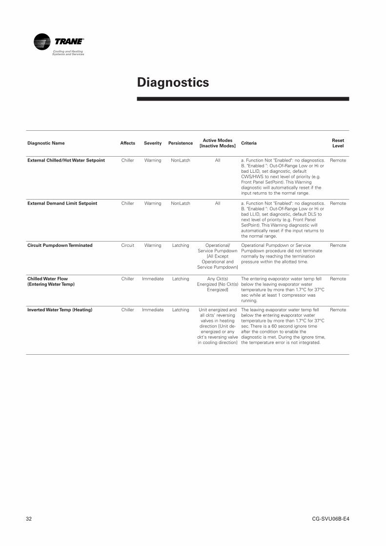
External Chilled/Hot Water Setpoint Chiller Warning NonLatch All a. Function Not "Enabled": no diagnostics.B. "Enabled ": Out-Of-Range Low or Hi orbad LLID, set diagnostic, defaultCWS/HWS to next level of priority (e.g.Front Panel SetPoint). This Warningdiagnostic will automatically reset if theinput returns to the normal range.
Remote
External Demand Limit Setpoint Chiller Warning NonLatch All a. Function Not "Enabled": no diagnostics.B. "Enabled ": Out-Of-Range Low or Hi orbad LLID, set diagnostic, default DLS tonext level of priority (e.g. Front PanelSetPoint). This Warning diagnostic willautomatically reset if the input returns tothe normal range.
Remote
Circuit Pumpdown Terminated Circuit Warning Latching Operational/Service Pumpdown
[All ExceptOperational and
Service Pumpdown]
Operational Pumpdown or ServicePumpdown procedure did not terminatenormally by reaching the terminationpressure within the allotted time.
Remote
Chilled Water Flow
(Entering Water Temp)
Chiller Immediate Latching Any Ckt(s)Energized [No Ckt(s)
Energized]
The entering evaporator water temp fellbelow the leaving evaporator watertemperature by more than 1.7°C for 37°Csec while at least 1 compressor wasrunning.
Remote
Inverted Water Temp (Heating) Chiller Immediate Latching Unit energized andall ckts' reversingvalves in heatingdirection [Unit de-energized or any
ckt's reversing valvein cooling direction]
The leaving evaporator water temp fellbelow the entering evaporator watertemperature by more than 1.7°C for 37°Csec. There is a 60 second ignore timeafter the condition to enable thediagnostic is met. During the ignore time,the temperature error is not integrated.
Remote
Diagnostics
33CG-SVU06B-E4
Diagnostic Name Affects Severity PersistenceActive Modes
[Inactive Modes]Criteria
Reset
Level
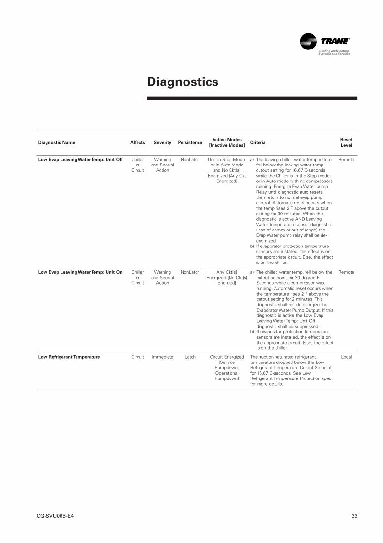
Low Evap Leaving Water Temp: Unit Off Chiller or
Circuit
Warningand Special
Action
NonLatch Unit in Stop Mode,or in Auto Mode
and No Ckt(s)Energized [Any Ckt
Energized]
a) The leaving chilled water temperaturefell below the leaving water tempcutout setting for 16.67 C-secondswhile the Chiller is in the Stop mode,or in Auto mode with no compressorsrunning. Energize Evap Water pumpRelay until diagnostic auto resets,then return to normal evap pumpcontrol. Automatic reset occurs whenthe temp rises 2 F above the cutoutsetting for 30 minutes. When thisdiagnostic is active AND LeavingWater Temperature sensor diagnostic(loss of comm or out of range) theEvap Water pump relay shall be de-energized.
b) If evaporator protection temperaturesensors are installed, the effect is onthe appropriate circuit. Else, the effectis on the chiller.
Remote
Low Evap Leaving Water Temp: Unit On Chiller or
Circuit
Warningand Special
Action
NonLatch Any Ckt[s]Energized [No Ckt(s)
Energizd]
a) The chilled water temp. fell below thecutout setpoint for 30 degree FSeconds while a compressor wasrunning. Automatic reset occurs whenthe temperature rises 2 F above thecutout setting for 2 minutes. Thisdiagnostic shall not de-energize theEvaporator Water Pump Output. If thisdiagnostic is active the Low EvapLeaving Water Temp: Unit Offdiagnostic shall be suppressed.
b) If evaporator protection temperaturesensors are installed, the effect is onthe appropriate circuit. Else, the effectis on the chiller.
Remote
Low Refrigerant Temperature Circuit Immediate Latch Circuit Energized[Service
Pumpdown,OperationalPumpdown]
The suction saturated refrigeranttemperature dropped below the LowRefrigerant Temperature Cutout Setpointfor 16.67 C-seconds. See LowRefrigerant Temperature Protection specfor more details.
Local
Diagnostics
CG-SVU06B-E434
Diagnostic Name Affects Severity PersistenceActive Modes
[Inactive Modes]Criteria
Reset
Level
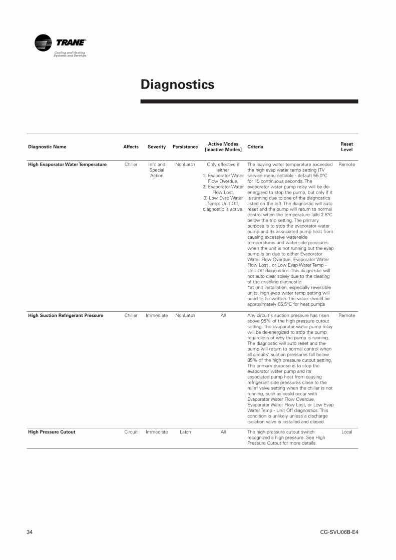
High Evaporator Water Temperature Chiller Info andSpecialAction
NonLatch Only effective ifeither
1) Evaporator WaterFlow Overdue,
2) Evaporator WaterFlow Lost,
3) Low Evap WaterTemp: Unit Off,
diagnostic is active.
The leaving water temperature exceededthe high evap water temp setting (TVservice menu settable - default 55.0°Cfor 15 continuous seconds. Theevaporator water pump relay will be de-energized to stop the pump, but only if itis running due to one of the diagnosticslisted on the left. The diagnostic will autoreset and the pump will return to normalcontrol when the temperature falls 2.8°Cbelow the trip setting. The primarypurpose is to stop the evaporator waterpump and its associated pump heat fromcausing excessive water-sidetemperatures and water-side pressureswhen the unit is not running but the evappump is on due to either EvaporatorWater Flow Overdue, Evaporator WaterFlow Lost , or Low Evap Water Temp -Unit Off diagnostics. This diagnostic willnot auto clear solely due to the clearingof the enabling diagnostic. *at unit installation, especially reversibleunits, high evap water temp setting willneed to be written. The value should beapproximately 65.5°C for heat pumps
Remote
High Suction Refrigerant Pressure Chiller Immediate NonLatch All Any circuit's suction pressure has risenabove 95% of the high pressure cutoutsetting. The evaporator water pump relaywill be de-energized to stop the pumpregardless of why the pump is running.The diagnostic will auto reset and thepump will return to normal control whenall circuits' suction pressures fall below85% of the high pressure cutout setting.The primary purpose is to stop theevaporator water pump and itsassociated pump heat from causingrefrigerant side pressures close to therelief valve setting when the chiller is notrunning, such as could occur withEvaporator Water Flow Overdue,Evaporator Water Flow Lost, or Low EvapWater Temp - Unit Off diagnostics. Thiscondition is unlikely unless a dischargeisolation valve is installed and closed.
Remote
High Pressure Cutout Circuit Immediate Latch All The high pressure cutout switchrecognized a high pressure. See HighPressure Cutout for more details.
Local
Diagnostics
35CG-SVU06B-E4
Diagnostic Name Affects Severity PersistenceActive Modes
[Inactive Modes]Criteria
Reset
Level
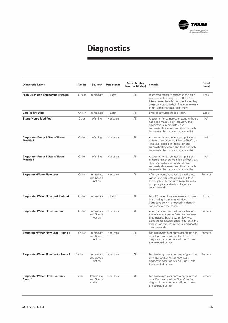
High Discharge Refrigerant Pressure Circuit Immediate Latch All Discharge pressure exceeded the highpressure cutout setpoint + 100 kPa.Likely cause: failed or incorrectly set highpressure cutout switch. Prevents releaseof refrigerant through relief valve.
Local
Emergency Stop Chiller Immediate Latch All Emergency Stop input is open. Local
Starts/Hours Modified Cprsr Warning NonLatch All A counter for compressor starts or hourshas been modified by TechView. Thisdiagnostic is immediately andautomatically cleared and thus can onlybe seen in the historic diagnostic list.
NA
Evaporator Pump 1 Starts/Hours
Modified
Chiller Warning NonLatch All A counter for evaporator pump 1 startsor hours has been modified by TechView.This diagnostic is immediately andautomatically cleared and thus can onlybe seen in the historic diagnostic list.
NA
Evaporator Pump 2 Starts/Hours
Modified
Chiller Warning NonLatch All A counter for evaporator pump 2 startsor hours has been modified by TechView.This diagnostic is immediately andautomatically cleared and thus can onlybe seen in the historic diagnostic list.
NA
Evaporator Water Flow Lost Chiller Immediateand Special
Action
NonLatch All After the pump request was activated,water flow was established and thenlost. Special action is to keep the evappump request active in a diagnosticoverride mode.
Remote
Evaporator Water Flow Lost Lockout Chiller Immediate Latch All Four (4) water flow loss events occurredin a moving 4 day time window.Corrective action is needed to identifyand eliminate the cause.
Local
Evaporator Water Flow Overdue Chiller Immediateand Special
Action
NonLatch All After the pump request was activated,the evaporator water flow overdue waittime elapsed before water flow wasestablished. Special action is to keep theevap pump request active in a diagnosticoverride mode.
Remote
Evaporator Water Flow Lost - Pump 1 Chiller Immediateand Special
Action
NonLatch All For dual evaporator pump configurationsonly. Evaporator Water Flow Lostdiagnostic occurred while Pump 1 wasthe selected pump.
Remote
Evaporator Water Flow Lost - Pump 2 Chiller Immediateand Special
Action
NonLatch All For dual evaporator pump configurationsonly. Evaporator Water Flow Lostdiagnostic occurred while Pump 2 wasthe selected pump.
Remote
Evaporator Water Flow Overdue -
Pump 1
Chiller Immediateand SpecialAction
NonLatch All For dual evaporator pump configurationsonly. Evaporator Water Flow Overduediagnostic occurred while Pump 1 wasthe selected pump.
Remote
Diagnostics
CG-SVU06B-E436
Diagnostic Name Affects Severity PersistenceActive Modes
[Inactive Modes]Criteria
Reset
Level
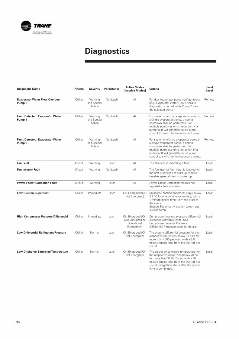
Evaporator Water Flow Overdue -
Pump 2
Chiller Warningand Special
Action
NonLatch All For dual evaporator pump configurationsonly. Evaporator Water Flow Overduediagnostic occurred while Pump 2 wasthe selected pump.
Remote
Fault Detected: Evaporator Water
Pump 1
Chiller Warningand Special
Action
NonLatch All For systems with no evaporator pump ora single evaporator pump, a normalshutdown shall be performed. Formultiple pump systems, detection of apump fault will generally cause pumpcontrol to switch to the redundant pump.
Remote
Fault Detected: Evaporator Water
Pump 2
Chiller Warningand Special
Action
NonLatch All For systems with no evaporator pump ora single evaporator pump, a normalshutdown shall be performed. Formultiple pump systems, detection of apump fault will generally cause pumpcontrol to switch to the redundant pump.
Remote
Fan Fault Circuit Warning Latch All The fan deck is indicating a fault. Local
Fan Inverter Fault Circuit Warning NonLatch All The fan inverter fault input is ignored forthe first 5 seconds of start up to allowvariable speed drives to power up.
Local
Power Factor Correction Fault Circuit Warning Latch All Power Factor Correction module hassignaled a fault condition.
Local
Low Suction Superheat Chiller Immediate Latch Ckt Energized [CktNot Energized]
Measured suction superheat stays below2.2 °C for one continuous minute, with a1 minute ignore time fro m the start ofthe circuit. Suction Superheat = suction temp - sat.suction temp.
Local
High Compressor Pressure Differential Chiller Immediate Latch Ckt Energized [CktNot Energized or
OperationalPumpdown]
Compressor involute pressure differentialexceeded allowable limits. SeeCompressor Involute PressureDifferential Protection spec for details.
Local
Low Differential Refrigerant Pressure Chiller Normal Latch Ckt Energized [CktNot Energized]
The system differential pressure for therespective circuit was below 90 psid formore than 4000 psid-sec, with a 2.5minute ignore time from the start of thecircuit.
Local
Low Discharge Saturated Temperature Chiller Normal Latch Ckt Energized [CktNot Energized]
The discharge saturated temperature forthe respective circuit was below 20 °Cfor more than 3750 °C-sec, with a 10minute ignore time from the start of thecircuit. Integration starts after the ignoretime is completed.
Local
Diagnostics
37CG-SVU06B-E4
Diagnostic Name Affects Severity Persistence
Active
Modes
[Inactive
Modes]
CriteriaReset
Level
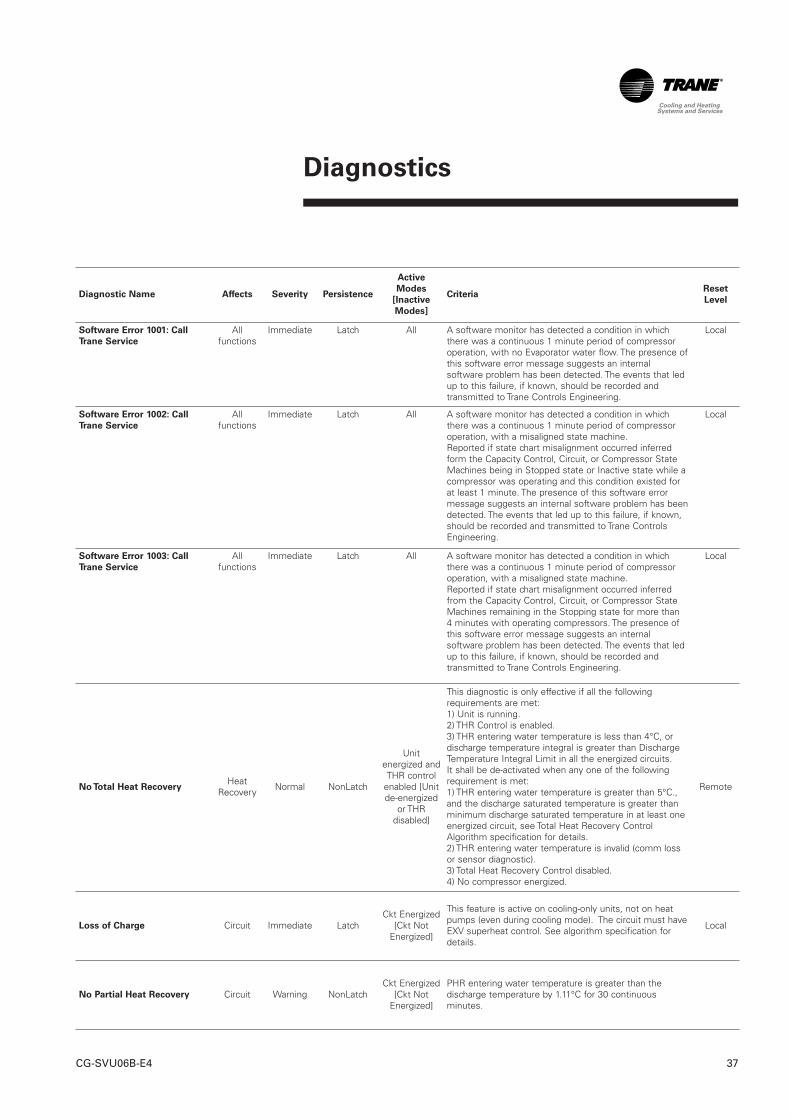
Software Error 1001: Call
Trane Service
Allfunctions
Immediate Latch All A software monitor has detected a condition in whichthere was a continuous 1 minute period of compressoroperation, with no Evaporator water flow. The presence ofthis software error message suggests an internalsoftware problem has been detected. The events that ledup to this failure, if known, should be recorded andtransmitted to Trane Controls Engineering.
Local
Software Error 1002: Call
Trane Service
Allfunctions
Immediate Latch All A software monitor has detected a condition in whichthere was a continuous 1 minute period of compressoroperation, with a misaligned state machine. Reported if state chart misalignment occurred inferredform the Capacity Control, Circuit, or Compressor StateMachines being in Stopped state or Inactive state while acompressor was operating and this condition existed forat least 1 minute. The presence of this software errormessage suggests an internal software problem has beendetected. The events that led up to this failure, if known,should be recorded and transmitted to Trane ControlsEngineering.
Local
Software Error 1003: Call
Trane Service
Allfunctions
Immediate Latch All A software monitor has detected a condition in whichthere was a continuous 1 minute period of compressoroperation, with a misaligned state machine. Reported if state chart misalignment occurred inferredfrom the Capacity Control, Circuit, or Compressor StateMachines remaining in the Stopping state for more than4 minutes with operating compressors. The presence ofthis software error message suggests an internalsoftware problem has been detected. The events that ledup to this failure, if known, should be recorded andtransmitted to Trane Controls Engineering.
Local
No Total Heat RecoveryHeat
Recovery Normal NonLatch
Unitenergized andTHR control
enabled [Unitde-energized
or THRdisabled]
This diagnostic is only effective if all the followingrequirements are met:1) Unit is running.2) THR Control is enabled.3) THR entering water temperature is less than 4°C, ordischarge temperature integral is greater than DischargeTemperature Integral Limit in all the energized circuits.It shall be de-activated when any one of the followingrequirement is met:1) THR entering water temperature is greater than 5°C.,and the discharge saturated temperature is greater thanminimum discharge saturated temperature in at least oneenergized circuit, see Total Heat Recovery ControlAlgorithm specification for details.2) THR entering water temperature is invalid (comm lossor sensor diagnostic).3) Total Heat Recovery Control disabled.4) No compressor energized.
Remote
Loss of Charge Circuit Immediate LatchCkt Energized
[Ckt NotEnergized]
This feature is active on cooling-only units, not on heatpumps (even during cooling mode). The circuit must haveEXV superheat control. See algorithm specification fordetails.
Local
No Partial Heat Recovery Circuit Warning NonLatchCkt Energized
[Ckt NotEnergized]
PHR entering water temperature is greater than thedischarge temperature by 1.11°C for 30 continuousminutes.
Diagnostics
CG-SVU06B-E438
Diagnostic Name Effects Severity Persistence Active Modes
[Inactive
Modes]
Criteria Reset
Level
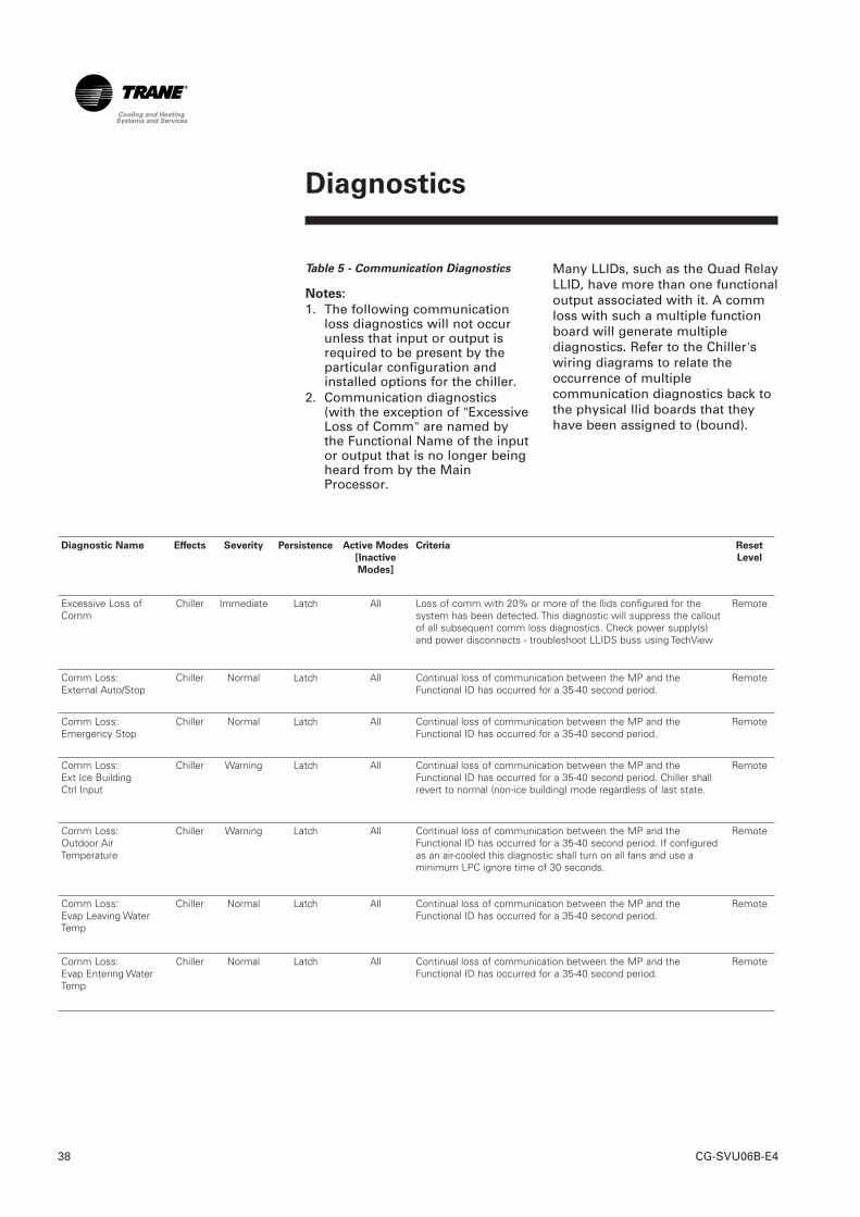
Excessive Loss ofComm
Chiller Immediate Latch All Loss of comm with 20% or more of the llids configured for thesystem has been detected. This diagnostic will suppress the calloutof all subsequent comm loss diagnostics. Check power supply(s)and power disconnects - troubleshoot LLIDS buss using TechView
Remote
Comm Loss: External Auto/Stop
Chiller Normal Latch All Continual loss of communication between the MP and theFunctional ID has occurred for a 35-40 second period.
Remote
Comm Loss: Emergency Stop
Chiller Normal Latch All Continual loss of communication between the MP and theFunctional ID has occurred for a 35-40 second period.
Remote
Comm Loss: Ext Ice BuildingCtrl Input
Chiller Warning Latch All Continual loss of communication between the MP and theFunctional ID has occurred for a 35-40 second period. Chiller shallrevert to normal (non-ice building) mode regardless of last state.
Remote
Comm Loss: Outdoor AirTemperature
Chiller Warning Latch All Continual loss of communication between the MP and theFunctional ID has occurred for a 35-40 second period. If configuredas an air-cooled this diagnostic shall turn on all fans and use aminimum LPC ignore time of 30 seconds.
Remote
Comm Loss: Evap Leaving WaterTemp
Chiller Normal Latch All Continual loss of communication between the MP and theFunctional ID has occurred for a 35-40 second period.
Remote
Comm Loss: Evap Entering WaterTemp
Chiller Normal Latch All Continual loss of communication between the MP and theFunctional ID has occurred for a 35-40 second period.
Remote
Table 5 - Communication Diagnostics
Notes:
1. The following communicationloss diagnostics will not occurunless that input or output isrequired to be present by theparticular configuration andinstalled options for the chiller.
2. Communication diagnostics(with the exception of "ExcessiveLoss of Comm" are named bythe Functional Name of the inputor output that is no longer beingheard from by the MainProcessor.
Many LLIDs, such as the Quad RelayLLID, have more than one functionaloutput associated with it. A commloss with such a multiple functionboard will generate multiplediagnostics. Refer to the Chiller'swiring diagrams to relate theoccurrence of multiplecommunication diagnostics back tothe physical llid boards that theyhave been assigned to (bound).
Diagnostics
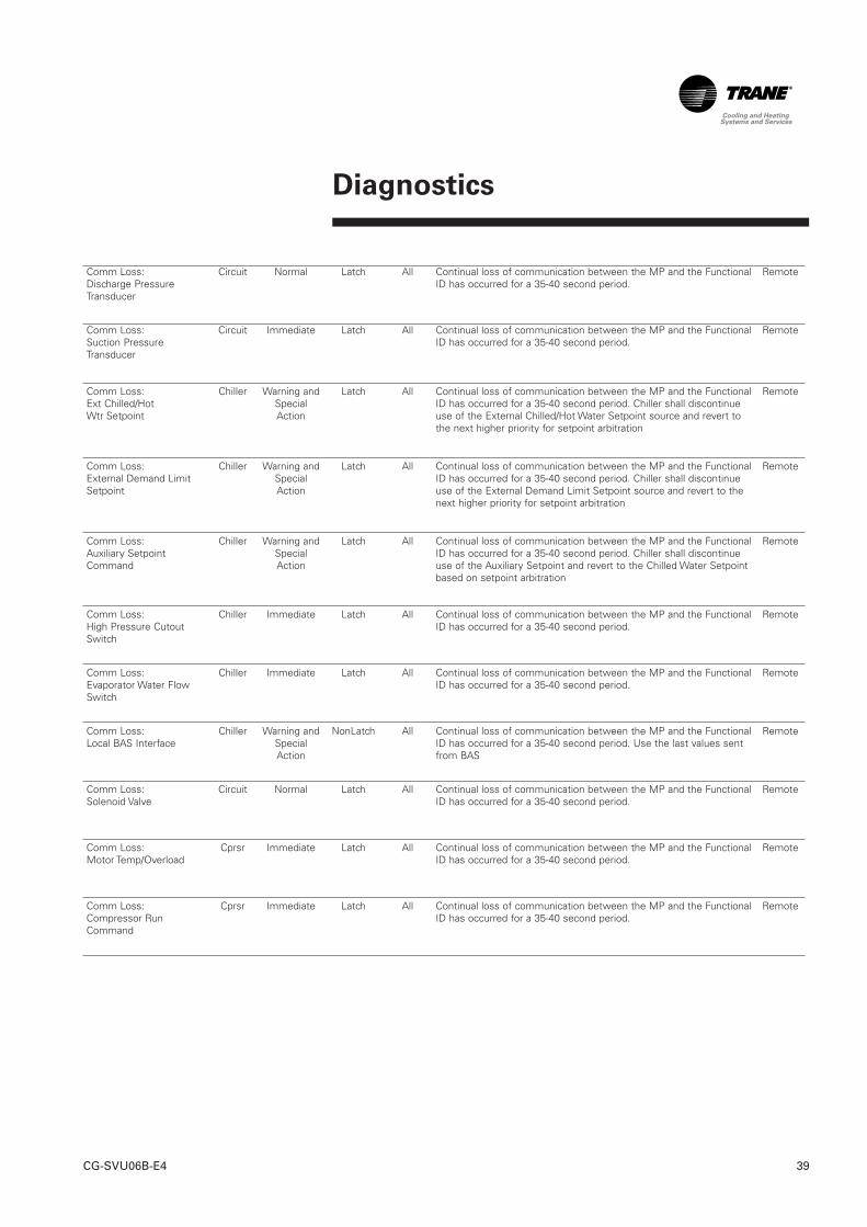
39CG-SVU06B-E4
Comm Loss: Discharge PressureTransducer
Circuit Normal Latch All Continual loss of communication between the MP and the FunctionalID has occurred for a 35-40 second period.
Remote
Comm Loss: Suction PressureTransducer
Circuit Immediate Latch All Continual loss of communication between the MP and the FunctionalID has occurred for a 35-40 second period.
Remote
Comm Loss: Ext Chilled/HotWtr Setpoint
Chiller Warning andSpecialAction
Latch All Continual loss of communication between the MP and the FunctionalID has occurred for a 35-40 second period. Chiller shall discontinueuse of the External Chilled/Hot Water Setpoint source and revert tothe next higher priority for setpoint arbitration
Remote
Comm Loss: External Demand LimitSetpoint
Chiller Warning andSpecialAction
Latch All Continual loss of communication between the MP and the FunctionalID has occurred for a 35-40 second period. Chiller shall discontinueuse of the External Demand Limit Setpoint source and revert to thenext higher priority for setpoint arbitration
Remote
Comm Loss: Auxiliary SetpointCommand
Chiller Warning andSpecialAction
Latch All Continual loss of communication between the MP and the FunctionalID has occurred for a 35-40 second period. Chiller shall discontinueuse of the Auxiliary Setpoint and revert to the Chilled Water Setpointbased on setpoint arbitration
Remote
Comm Loss: High Pressure CutoutSwitch
Chiller Immediate Latch All Continual loss of communication between the MP and the FunctionalID has occurred for a 35-40 second period.
Remote
Comm Loss: Evaporator Water FlowSwitch
Chiller Immediate Latch All Continual loss of communication between the MP and the FunctionalID has occurred for a 35-40 second period.
Remote
Comm Loss: Local BAS Interface
Chiller Warning andSpecialAction
NonLatch All Continual loss of communication between the MP and the FunctionalID has occurred for a 35-40 second period. Use the last values sentfrom BAS
Remote
Comm Loss: Solenoid Valve
Circuit Normal Latch All Continual loss of communication between the MP and the FunctionalID has occurred for a 35-40 second period.
Remote
Comm Loss: Motor Temp/Overload
Cprsr Immediate Latch All Continual loss of communication between the MP and the FunctionalID has occurred for a 35-40 second period.
Remote
Comm Loss: Compressor RunCommand
Cprsr Immediate Latch All Continual loss of communication between the MP and the FunctionalID has occurred for a 35-40 second period.
Remote
Diagnostics
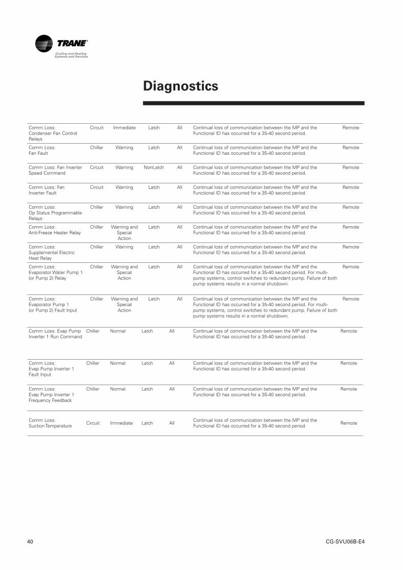
CG-SVU06B-E440
Comm Loss: Condenser Fan ControlRelays
Circuit Immediate Latch All Continual loss of communication between the MP and theFunctional ID has occurred for a 35-40 second period.
Remote
Comm Loss: Fan Fault
Chiller Warning Latch All Continual loss of communication between the MP and theFunctional ID has occurred for a 35-40 second period.
Remote
Comm Loss: Fan InverterSpeed Command
Circuit Warning NonLatch All Continual loss of communication between the MP and theFunctional ID has occurred for a 35-40 second period.
Remote
Comm Loss: Fan Inverter Fault
Circuit Warning Latch All Continual loss of communication between the MP and theFunctional ID has occurred for a 35-40 second period.
Remote
Comm Loss: Op Status ProgrammableRelays
Chiller Warning Latch All Continual loss of communication between the MP and theFunctional ID has occurred for a 35-40 second period.
Remote
Comm Loss: Anti-Freeze Heater Relay
Chiller Warning andSpecialAction
Latch All Continual loss of communication between the MP and theFunctional ID has occurred for a 35-40 second period.
Remote
Comm Loss:Supplemental ElectricHeat Relay
Chiller Warning Latch All Continual loss of communication between the MP and theFunctional ID has occurred for a 35-40 second period.
Remote
Comm Loss: Evaporator Water Pump 1(or Pump 2) Relay
Chiller Warning andSpecialAction
Latch All Continual loss of communication between the MP and theFunctional ID has occurred for a 35-40 second period. For multi-pump systems, control switches to redundant pump. Failure of bothpump systems results in a normal shutdown.
Remote
Comm Loss: Evaporator Pump 1(or Pump 2) Fault Input
Chiller Warning andSpecialAction
Latch All Continual loss of communication between the MP and theFunctional ID has occurred for a 35-40 second period. For multi-pump systems, control switches to redundant pump. Failure of bothpump systems results in a normal shutdown.
Remote
Comm Loss: Evap PumpInverter 1 Run Command
Chiller Normal Latch All Continual loss of communication between the MP and theFunctional ID has occurred for a 35-40 second period.
Remote
Comm Loss:Evap Pump Inverter 1Fault Input
Chiller Normal Latch All Continual loss of communication between the MP and theFunctional ID has occurred for a 35-40 second period.
Remote
Comm Loss:Evap Pump Inverter 1Frequency Feedback
Chiller Normal Latch All Continual loss of communication between the MP and theFunctional ID has occurred for a 35-40 second period.
Remote
Comm Loss:Suction Temperature Circuit Immediate Latch All Continual loss of communication between the MP and the
Functional ID has occurred for a 35-40 second period. Remote
Diagnostics
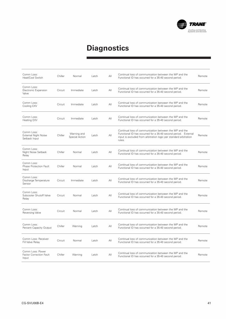
41CG-SVU06B-E4
Comm Loss:Heat/Cool Switch Chiller Normal Latch All Continual loss of communication between the MP and the
Functional ID has occurred for a 35-40 second period. Remote
Comm Loss:Electronic ExpansionValve
Circuit Immediate Latch All Continual loss of communication between the MP and theFunctional ID has occurred for a 35-40 second period. Remote
Comm Loss:Cooling EXV Circuit Immediate Latch All Continual loss of communication between the MP and the
Functional ID has occurred for a 35-40 second period. Remote
Comm Loss:Heating EXV Circuit Immediate Latch All Continual loss of communication between the MP and the
Functional ID has occurred for a 35-40 second period. Remote
Comm Loss:External Night NoiseSetback Input
Chiller Warning andSpecial Action Latch All
Continual loss of communication between the MP and theFunctional ID has occurred for a 35-40 second period. Externalinput is excluded from arbitration logic per standard arbitrationrules.
Remote
Comm Loss:Night Noise SetbackRelay
Chiller Normal Latch All Continual loss of communication between the MP and theFunctional ID has occurred for a 35-40 second period. Remote
Comm Loss:Phase Protection FaultInput
Chiller Normal Latch All Continual loss of communication between the MP and theFunctional ID has occurred for a 35-40 second period. Remote
Comm Loss:Discharge TemperatureSensor
Circuit Immediate Latch All Continual loss of communication between the MP and theFunctional ID has occurred for a 35-40 second period. Remote
Comm Loss:Subcooler Shutoff ValveRelay
Circuit Normal Latch All Continual loss of communication between the MP and theFunctional ID has occurred for a 35-40 second period. Remote
Comm Loss:Reversing Valve Circuit Normal Latch All Continual loss of communication between the MP and the
Functional ID has occurred for a 35-40 second period. Remote
Comm Loss:Percent Capacity Output Chiller Warning Latch All Continual loss of communication between the MP and the
Functional ID has occurred for a 35-40 second period. Remote
Comm Loss: ReceiverFill Valve Relay Circuit Normal Latch All Continual loss of communication between the MP and the
Functional ID has occurred for a 35-40 second period. Remote
Comm Loss: PowerFactor Correction FaultInput
Chiller Warning Latch All Continual loss of communication between the MP and theFunctional ID has occurred for a 35-40 second period. Remote
CG-SVU02C-E442
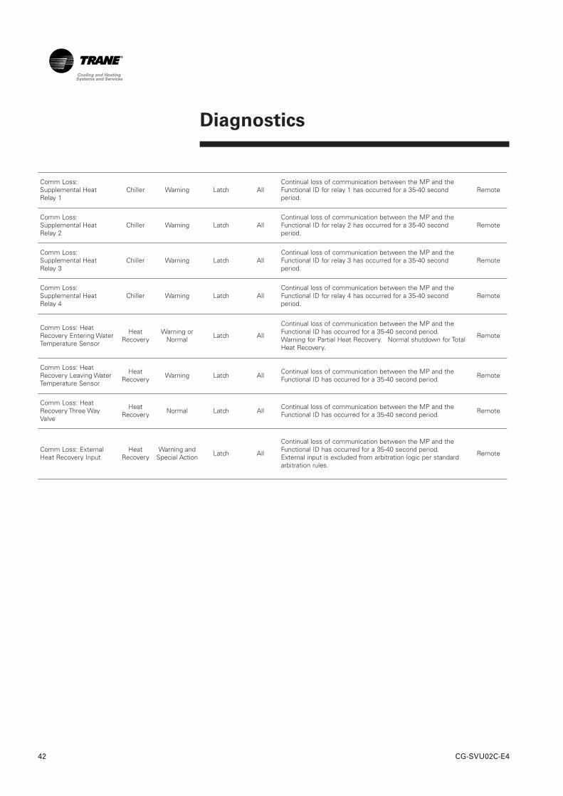
Comm Loss:Supplemental HeatRelay 1
Chiller Warning Latch AllContinual loss of communication between the MP and theFunctional ID for relay 1 has occurred for a 35-40 secondperiod.
Remote
Comm Loss:Supplemental HeatRelay 2
Chiller Warning Latch AllContinual loss of communication between the MP and theFunctional ID for relay 2 has occurred for a 35-40 secondperiod.
Remote
Comm Loss:Supplemental HeatRelay 3
Chiller Warning Latch AllContinual loss of communication between the MP and theFunctional ID for relay 3 has occurred for a 35-40 secondperiod.
Remote
Comm Loss:Supplemental HeatRelay 4
Chiller Warning Latch AllContinual loss of communication between the MP and theFunctional ID for relay 4 has occurred for a 35-40 secondperiod.
Remote
Comm Loss: HeatRecovery Entering WaterTemperature Sensor
HeatRecovery
Warning orNormal Latch All
Continual loss of communication between the MP and theFunctional ID has occurred for a 35-40 second period.Warning for Partial Heat Recovery. Normal shutdown for TotalHeat Recovery.
Remote
Comm Loss: HeatRecovery Leaving WaterTemperature Sensor
HeatRecovery Warning Latch All Continual loss of communication between the MP and the
Functional ID has occurred for a 35-40 second period. Remote
Comm Loss: HeatRecovery Three WayValve
HeatRecovery Normal Latch All Continual loss of communication between the MP and the
Functional ID has occurred for a 35-40 second period. Remote
Comm Loss: ExternalHeat Recovery Input
HeatRecovery
Warning andSpecial Action Latch All
Continual loss of communication between the MP and theFunctional ID has occurred for a 35-40 second period.External input is excluded from arbitration logic per standardarbitration rules.
Remote
Diagnostics
43CG-SVU02C-E4
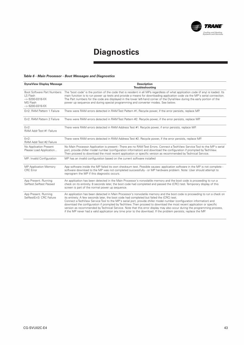
Table 6 - Main Processor - Boot Messages and Diagnostics
DynaView Display Message Description
Troubleshooting
Boot Software Part Numbers:LS Flash --> 6200-0318-XXMS Flash --> 6200-0319-XX
The "boot code" is the portion of the code that is resident in all MPs regardless of what application code (if any) is loaded. Itsmain function is to run power up tests and provide a means for downloading application code via the MP's serial connection.The Part numbers for the code are displayed in the lower left-hand corner of the DynaView during the early portion of thepower up sequence and during special programming and converter modes. See below.
Err2: RAM Pattern 1 Failure There were RAM errors detected in RAM Test Pattern #1. Recycle power, if the error persists, replace MP.
Err2: RAM Pattern 2 Failure There were RAM errors detected in RAM Test Pattern #2. Recycle power, if the error persists, replace MP.
Err2: RAM Addr Test #1 Failure
There were RAM errors detected in RAM Address Test #1. Recycle power, if error persists, replace MP.
Err2: RAM Addr Test #2 Failure
There were RAM errors detected in RAM Address Test #2. Recycle power, if the error persists, replace MP.
No Application PresentPlease Load Application...
No Main Processor Application is present - There are no RAM Test Errors. Connect a TechView Service Tool to the MP's serialport, provide chiller model number (configuration information) and download the configuration if prompted by TechView.Then proceed to download the most recent application or specific version as recommended by Technical Service.
MP: Invalid Configuration MP has an invalid configuration based on the current software installed
MP Application MemoryCRC Error
App software inside the MP failed its own checksum test. Possible causes: application software in the MP is not complete -software download to the MP was not completed successfully - or MP hardware problem. Note: User should attempt toreprogram the MP if this diagnostic occurs.
App Present. RunningSelftest.Selftest Passed
An application has been detected in the Main Processor's nonvolatile memory and the boot code is proceeding to run acheck on its entirety. 8 seconds later, the boot code had completed and passed the (CRC) test. Temporary display of thisscreen is part of the normal power up sequence.
App Present. RunningSelftestErr3: CRC Failure
An application has been detected in Main Processor's nonvolatile memory and the boot code is proceeding to run a check onits entirety. A few seconds later, the boot code had completed but failed the (CRC) test. Connect a TechView Service Tool to the MP's serial port, provide chiller model number (configuration information) anddownload the configuration if prompted by TechView. Then proceed to download the most recent application or specificversion as recommended by Technical Service. Note that this error display may also occur during the programming process,if the MP never had a valid application any time prior to the download. If the problem persists, replace the MP.
Diagnostics
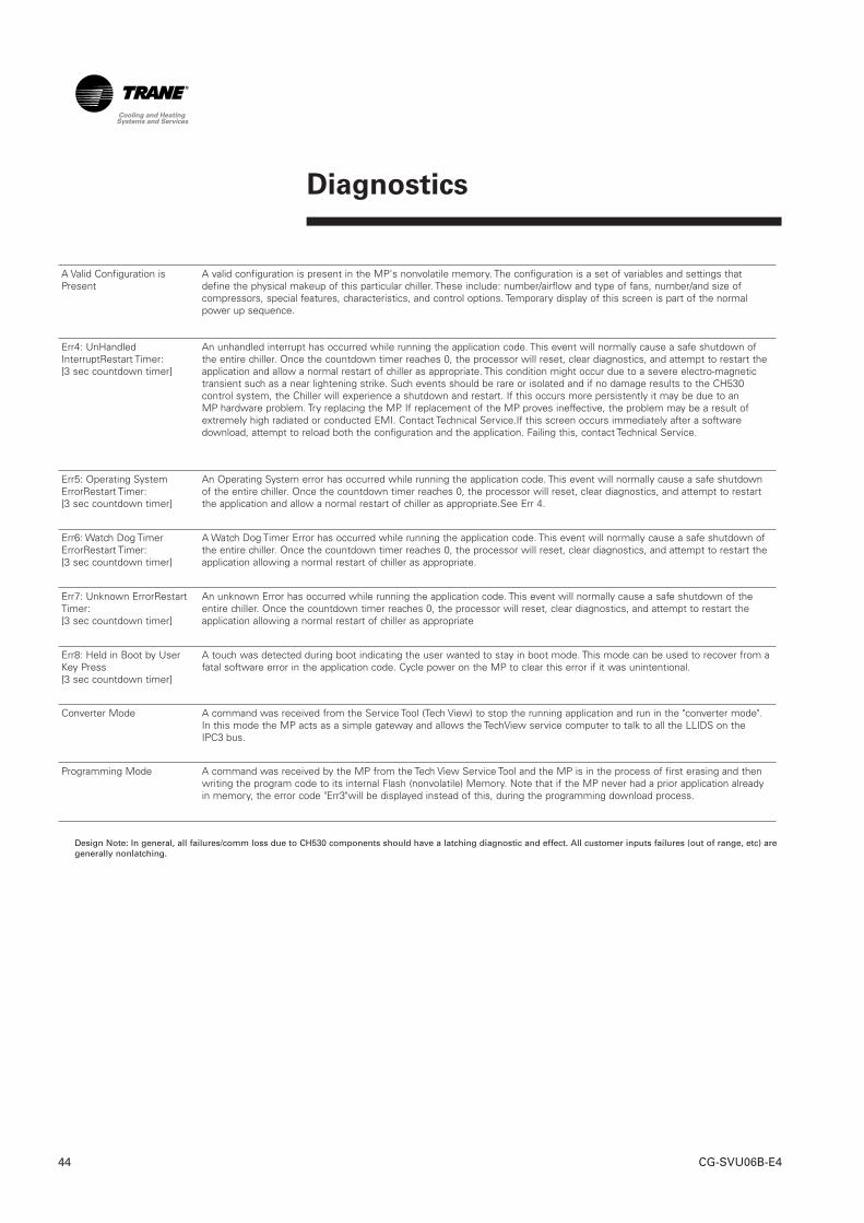
Diagnostics
CG-SVU06B-E444
A Valid Configuration isPresent
A valid configuration is present in the MP's nonvolatile memory. The configuration is a set of variables and settings thatdefine the physical makeup of this particular chiller. These include: number/airflow and type of fans, number/and size ofcompressors, special features, characteristics, and control options. Temporary display of this screen is part of the normalpower up sequence.
Err4: UnHandledInterruptRestart Timer:[3 sec countdown timer]
An unhandled interrupt has occurred while running the application code. This event will normally cause a safe shutdown ofthe entire chiller. Once the countdown timer reaches 0, the processor will reset, clear diagnostics, and attempt to restart theapplication and allow a normal restart of chiller as appropriate. This condition might occur due to a severe electro-magnetictransient such as a near lightening strike. Such events should be rare or isolated and if no damage results to the CH530control system, the Chiller will experience a shutdown and restart. If this occurs more persistently it may be due to anMP hardware problem. Try replacing the MP. If replacement of the MP proves ineffective, the problem may be a result ofextremely high radiated or conducted EMI. Contact Technical Service.If this screen occurs immediately after a softwaredownload, attempt to reload both the configuration and the application. Failing this, contact Technical Service.
Err5: Operating SystemErrorRestart Timer:[3 sec countdown timer]
An Operating System error has occurred while running the application code. This event will normally cause a safe shutdownof the entire chiller. Once the countdown timer reaches 0, the processor will reset, clear diagnostics, and attempt to restartthe application and allow a normal restart of chiller as appropriate.See Err 4.
Err6: Watch Dog TimerErrorRestart Timer:[3 sec countdown timer]
A Watch Dog Timer Error has occurred while running the application code. This event will normally cause a safe shutdown ofthe entire chiller. Once the countdown timer reaches 0, the processor will reset, clear diagnostics, and attempt to restart theapplication allowing a normal restart of chiller as appropriate.
Err7: Unknown ErrorRestartTimer:[3 sec countdown timer]
An unknown Error has occurred while running the application code. This event will normally cause a safe shutdown of theentire chiller. Once the countdown timer reaches 0, the processor will reset, clear diagnostics, and attempt to restart theapplication allowing a normal restart of chiller as appropriate
Err8: Held in Boot by UserKey Press[3 sec countdown timer]
A touch was detected during boot indicating the user wanted to stay in boot mode. This mode can be used to recover from afatal software error in the application code. Cycle power on the MP to clear this error if it was unintentional.
Converter Mode A command was received from the Service Tool (Tech View) to stop the running application and run in the "converter mode".In this mode the MP acts as a simple gateway and allows the TechView service computer to talk to all the LLIDS on theIPC3 bus.
Programming Mode A command was received by the MP from the Tech View Service Tool and the MP is in the process of first erasing and thenwriting the program code to its internal Flash (nonvolatile) Memory. Note that if the MP never had a prior application alreadyin memory, the error code "Err3"will be displayed instead of this, during the programming download process.
Design Note: In general, all failures/comm loss due to CH530 components should have a latching diagnostic and effect. All customer inputs failures (out of range, etc) aregenerally nonlatching.
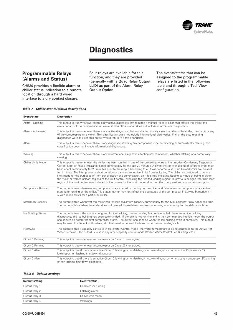
Diagnostics
45CG-SVU06B-E4
Programmable Relays
(Alarms and Status)
CH530 provides a flexible alarm orchiller status indication to a remotelocation through a hard wiredinterface to a dry contact closure.
Four relays are available for thisfunction, and they are provided(generally with a Quad Relay OutputLLID) as part of the Alarm RelayOutput Option.
The events/states that can beassigned to the programmablerelays are listed in the followingtable and through a TechViewconfiguration.
Event/state Description
Alarm - Latching This output is true whenever there is any active diagnostic that requires a manual reset to clear, that affects the chiller, thecircuit, or any of the compressors on a circuit. This classification does not include informational diagnostics.
Alarm - Auto reset This output is true whenever there is any active diagnostic that could automatically clear that affects the chiller, the circuit or anyof the compressors on a circuit. This classification does not include informational diagnostics. If all of the auto resettingdiagnostics were to clear, this output would return to a false condition.
Alarm This output is true whenever there is any diagnostic affecting any component, whether latching or automatically clearing. Thisclassification does not include informational diagnostics.
Warning This output is true whenever there is any informational diagnostic affecting any component, whether latching or automaticallyclearing.
Chiller Limit Mode This output is true whenever the chiller has been running in one of the Unloading types of limit modes (Condenser, Evaporator,Current Limit or Phase Imbalance Limit) continuously for the last 20 minutes. A given limit or overlapping of different limits mustbe in effect continuously for 20 minutes prior to the output becoming true. It will become false, if no Unload limits are presentfor 1 minute. The filter prevents short duration or transient repetitive limits from indicating. The chiller is considered to be in alimit mode for the purposes of front panel display and annunciation, on if it is fully inhibiting loading by virtue of being in eitherthe "hold" or "forced unload" regions of the limit control, excluding the "limited loading region". In previous designs, the "limit load"region of the limit control was included in the criteria for the limit mode call out on the front panel and annunciation outputs.
Compressor Running The output is true whenever any compressors are started or running on the chiller and false when no compressors are eitherstarting or running on the chiller. This status may or may not reflect the true status of the compressor in Service Pumpdown ifsuch a mode exists for a particular chiller.
Maximum Capacity The output is true whenever the chiller has reached maximum capacity continuously for the Max Capacity Relay debounce time.The output is false when the chiller does not have all its available compressors running continuously for the debounce time.
Ice Building Status The output is true if the unit is configured for ice building, the ice building feature is enabled, there are no ice buildingdiagnostics, and ice building has been commanded. If the unit is not running and is then commanded into ice mode, the outputshould turn on before the first compressor starts. The output should false when the ice building cycle is complete. This outputmay be used to interlock with valves, etc. that need to be switched over to do the ice building cycle.
Heat/Cool The output is true if capacity control is in Hot Water Control mode (the water temperature is being controlled to the Active HotWater Setpoint). The output is false in any other capacity control mode (Chilled Water Control, Ice Building, etc.).
Circuit 1 Running This output is true whenever a compressor on Circuit 1 is energized.
Circuit 2 Running This output is true whenever a compressor on Circuit 2 is energized.
Circuit 1 Alarm This output is true if there is an active Circuit 1 latching or non-latching shutdown diagnostic, or an active Compressor 1Xlatching or non-latching shutdown diagnostic.
Circuit 2 Alarm This output is true if there is an active Circuit 2 latching or non-latching shutdown diagnostic, or an active compressor 2X latchingor non-latching shutdown diagnostic.
Default setting Event/Status
Output relay 1 Compressor running
Output relay 2 Latching alarm
Output relay 3 Chiller limit mode
Output relay 4 Warnings
Table 7 - Chiller events/status descriptions
Table 8 - Default settings
TechView Interface
CG-SVU06B-E446
TechView is the PC (laptop) basedtool used for servicing TracerCH530. Technicians that make anychiller control modification orservice any diagnostic with TracerCH530 must use a laptop runningthe software application"TechView." TechView is a Traneapplication developed to minimizechiller downtime and aid thetechnicians' understanding of chilleroperation and service requirements.
CAUTION: Performing any TracerCH530 service functions should bedone only by a properly trainedservice technician. Please contactyour local Trane service agency forassistance with any servicerequirements. TechView software isavailable via Trane.com.(http://www.trane.com/commercial/software/tracerch530/) Thisdownload site provides a user theTechView installation software andCH530 main processor software thatmust be loaded onto your PC inorder to service a CH530 mainprocessor. The TechView servicetool is used to load software intothe Tracer CH530 main processor.
Minimum PC requirements to installand operate TechView are:• Pentium II or higher processor• 128Mb RAM• 1024 x 768 resolution of display• CD-ROM• 56K modem• 9-pin RS-232 serial connection• Operating system - Windows XP
Pro or Vista Business• USB 2.0 or higher• Internet Explorer 6.0 or higherNote: TechView was designed forthe proceeding listed laptopconfiguration. Any variation willhave unknown results. Therefore,support for TechView is limited toonly those operating systems thatmeet the specific configurationlisted here. KestrelView is designedand validated for this specific laptopconfiguration. Any variation fromthis configuration may havedifferent results. Therefore, supportfor KestrelView is limited to onlythose laptops configured asdescribed above. Trane will notsupport KestrelView on a laptopconfigured differently. There is nosupport for laptops running IntelCeleron, AMD, Cyrix, or processorsother than Pentium. Only laptopswith a Pentium II class processor orbetter are supported.
TechView is also used to performany CH530 service or maintenancefunction.
Servicing a CH530 main processorincludes:• Updating main processor
software• Monitoring chiller operation• Viewing and resetting chiller
diagnostics• Low Level Intelligent Device
(LLID) replacement and binding• Main processor replacement and
configuration modifications• Setpoint modifications• Service overrides
TechView Interface
47CG-SVU06B-E4
TechView installation has beensimplified. All related software,including Main Processor software,is now packaged together with theTechView application resulting in asingle installation.
Note: You do not have to uninstallan earlier version of TechView.The new TechView will updatethe existing files.
To install TechView on your
computer
1. Create a new folder titled CH530(C:\CH530) on your hard drive.This \CH530 folder is thestandard location for theinstallation file. Storing theinstallation file in this locationhelps you remember where it isstored and makes it easier fortechnical support personnel toassist you.
2. Click the Download link for thelatest version on the TechViewSoftware Download page. The File Download – SecurityWarning dialog box appears.
3. Click Save to copy the installationfile to your hard drive.Specify the \CH530 folder youcreated in Step 1 on the Savedialog box.
4. Double-click the installation (.exe)file.The License Agreement dialogbox appears.
5. Click I Agree after reviewing theLicense Agreement.
The Choose Components dialog boxappears. All components areselected by default. (These are theactual MP versions for all units.)Deselect any components you donot want included in theinstallation.
Note: Deselecting componentsreduces the size of the installedapplication.
6. Click Install.The Installation dialog appearswith a progress meter indicatingthe percentage of the installationthat has occurred. An installationinformation file appears whenthe installation is complete.
7. Click Close to exit the installationroutine.

Notes
CG-SVU06B-E448

49CG-SVU06B-E4
Notes

CG-SVU06B-E450
Notes

51CG-SVU06B-E4
Notes

Literature Order Number CG-SVU06B-E4
Date 1110
Supersedes CG-SVU06A-E4_0909
Trane has a policy of continuous product and product data improvement and reserves the right tochange design and specifications without notice. Only qualified technicians should perform theinstallation and servicing of equipment referred to in this publication.
www.trane.com
For more information, contact your local sales office or e-mail us at [email protected]
Trane bvba Lenneke Marelaan 6 -1932 Sint-Stevens-Woluwe, BelgiumON 0888.048.262 - RPR BRUSSELS