Embed Size (px)
Citation preview
USER GUIDE
NodeGrid Serial Console™
NodeGrid Manager ®
NodeGrid [CI] ™

U.S. Notification
WARNING: Changes or modifications to this unit not expressly approved by the party responsible for compliance could void the user’s authority to operate the equipment.
All other marks are the property of their respective owners. This document may contain confidential and/or proprietary information of ZPE Systems, Inc., and its receipt or possession does not convey any right to reproduce, disclose its contents, or to manufacture or sell anything that it may describe.
Reproduction, disclosure, or use without specific authorization from ZPE Systems, Inc. is strictly prohibited.
©2015 ZPE Systems, Inc. All rights reserved.
3/159 ZPE Systems, Inc. NodeGrid Manual
Contents
1. NODEGRID SERIAL CONSOLE OVERVIEW ............................................................................................... 7
1.1. Features and Benefits .................................................................................... 7
1.2. Secure access options ................................................................................... 8
1.3. System management .................................................................................... 8
1.4. Access Protocols ........................................................................................... 9
1.5. Device View Options ...................................................................................... 9
1.6. Power Management ....................................................................................... 9
1.7. Security ....................................................................................................... 9
1.8. Data Logging, Notifications and Alarms .......................................................... 10
1.9. Configuration Example ................................................................................ 10
2. NODEGRID [CI] OVERVIEW ................................................................................................................. 12
3. NODEGRID MANAGER OVERVIEW ...................................................................................................... 14
3.1 NodeGrid Manager Features ......................................................................... 15
3.2 Supported Console Protocols ........................................................................ 15
3.3 Benefits ..................................................................................................... 15
3.4 NodeGrid Manager System Requirements ...................................................... 16
3.5 Access Options ........................................................................................... 17
3.6 Authentication ............................................................................................ 17
3.7 Flexible Groups and Users ............................................................................ 17
3.8 Managed Devices and Auto-discovery ............................................................ 17
3.9 Data Logging, Event Logging, Alerts and Notifications ..................................... 18
3.10 Security Services and Firewall ...................................................................... 18
3.11 MKS, SOL, Virtual Serial, Physical Serial and Power ......................................... 18
3.12 IPv4 and IPv6 Support ................................................................................ 19
3.13 SNMP ........................................................................................................ 19
TABLE OF CONTENTS
4/159 ZPE Systems, Inc. NodeGrid Manual
4. NODEGRID SERIAL CONSOLE INSTALLATION ........................................................................................ 20
4.1 What is in the box? ..................................................................................... 20
4.2 Quick Start Instructions ............................................................................... 21
5. NODEGRID MANAGER INSTALLATION & DEPLOYMENT ....................................................................... 30
5.1 Creating a Virtual Machine ........................................................................... 30
5.2 Installing NodeGrid Manager ........................................................................ 31
5.3 Initial NodeGrid Manager Setup .................................................................... 31
6. ACCESS & TRACKING .......................................................................................................................... 34
6.1 Web, SSH or Telnet ..................................................................................... 34
6.2 Access Views and Searching Managed Devices ................................................ 35
6.3 Accessing the Managed Devices and Serial Devices via Telnet or SSH ................ 39
6.3.1 How to Telnet to a Managed Devices .......................................................... 39
6.3.2 How to close your Telnet session ............................................................... 42
6.3.3 How to SSH to a device through a serial port .............................................. 42
6.3.4 How to close your SSH Session .................................................................. 44
6.4 Tracking .................................................................................................... 44
7. SYSTEM ............................................................................................................................................. 46
7.1 License ...................................................................................................... 46
7.2 Preferences ................................................................................................ 46
7.3 Date and Time ............................................................................................ 48
7.4 Toolkit ....................................................................................................... 48
7.5 Logging ..................................................................................................... 49
7.6 Custom Fields ............................................................................................. 49
8. NETWORK .......................................................................................................................................... 50
8.1 Settings ..................................................................................................... 50
8.2 Connections ............................................................................................... 50
8.3 Static Routes .............................................................................................. 51
8.4 Hosts ........................................................................................................ 52
8.5 SNMP ........................................................................................................ 52
8.6 DHCP Server .............................................................................................. 52
8.7 SSL VPN .................................................................................................... 52
9. MANAGED DEVICES ............................................................................................................................. 54
9.1 Devices ..................................................................................................... 54
9.1.1 Adding Servers with Service Processor Support ........................................... 54
9.1.2 Adding Devices with SSH or Telnet Support................................................. 56
5/159 ZPE Systems, Inc. NodeGrid Manual
9.1.3 Adding Virtual Machines ............................................................................ 57
9.1.4 Adding Console Servers ............................................................................ 59
9.1.5 Adding NetApp storage device ................................................................... 60
9.1.6 Adding Power Strips (PDU) ........................................................................ 61
9.1.7 Adding KVM ............................................................................................ 63
9.1.8 Access .................................................................................................... 64
9.1.9 Management ........................................................................................... 67
9.1.10 Logging .................................................................................................. 68
9.1.11 Custom Fields .......................................................................................... 68
9.1.12 Commands ............................................................................................. 68
9.2 Views ........................................................................................................ 70
9.3 Types ........................................................................................................ 71
9.4 Auto Discovery ........................................................................................... 71
9.4.1 Network Scan .......................................................................................... 71
9.4.2 VM Manager ............................................................................................ 72
9.4.3 Discovery Rules ....................................................................................... 72
9.4.4 Hostname Detection ................................................................................. 76
9.4.5 Discovery Logs ........................................................................................ 76
9.4.6 Discover Now .......................................................................................... 77
10. CLOUD ............................................................................................................................................... 78
10.1 Peers......................................................................................................... 78
10.2 Settings ..................................................................................................... 78
10.3 Management .............................................................................................. 79
11. SECURITY ........................................................................................................................................... 81
11.1 Local Accounts ........................................................................................... 81
11.2 Authorization .............................................................................................. 83
11.3 Authentication ............................................................................................ 85
11.3.1 Setting authentication type ....................................................................... 85
11.4 Firewall ..................................................................................................... 87
11.5 Services .................................................................................................... 88
12. AUDITING ......................................................................................................................................... 91
12.1 Event Destination ....................................................................................... 91
12.2 Logging Destination .................................................................................... 92
13. DASHBOARD ..................................................................................................................................... 94
13.1 Customizing a Monitoring Template ............................................................... 94

6/159 ZPE Systems, Inc. NodeGrid Manual
13.1.1 SNMP Template ....................................................................................... 94
13.1.2 Discovery Template.................................................................................. 96
13.2 Enabling Monitoring .................................................................................... 97
13.2.1 Using the CLI .......................................................................................... 97
13.2.2 Using the Web Interface ........................................................................... 98
13.3 Exploring Data Points ................................................................................ 101
13.4 Creating a Visualization ............................................................................. 105
13.5 Creating a Dashboard ................................................................................ 110
13.6 Inspecting a Dashboard ............................................................................. 112
13.7 Additional Considerations ........................................................................... 113
14. APPLICATIONS ................................................................................................................................ 119
14.1 Installing Docker on Nodegrid..................................................................... 120
14.2 Running your first container ....................................................................... 120
TECHNICAL SUPPORT ............................................................................................................................... 123
APPENDIX A – Recovery Procedures ......................................................................................................... 124
APPENDIX B – DC Power ........................................................................................................................... 129
APPENDIX C – Configuring Virtual Serial Port on VMs ................................................................................ 131
APPENDIX D - OpenVPN ........................................................................................................................... 134
APPENDIX E – FailOver + VPN Test ............................................................................................................ 148
APPENDIX F – VLAN / BONDING ............................................................................................................... 156
7/159 ZPE Systems, Inc. NodeGrid Manual
Your new NodeGrid Serial Console (NSC) T Series console server provides fast, secure in-
band (Ethernet) and out-of-band (serial/USB cellular modem) management and control
of all your serially connected data center IT devices. The NodeGrid Serial Console family
of console servers/switches includes 16, 32, 48 and 96 port editions with dual DC or
single/dual AC power supplies.
1.1. Features and Benefits
Overview
Secure in-band and out-of-band access to serial devices via web portal,
command line and direct Linux shell for power users
High density 96, 48, 32 or 16 serial port models with dual/single AC power
supply or dual DC power supply
Modern 64-bit Linux 3.x kernel and software defined capabilities
Docker-optimized for DevOps-friendly flexible script and application integration,
without impeding core console server functionality
HTML5 remote console access for mobile, tablet, desktop – no more Java
dependencies
Vendor-neutral power management: Cyclades/Avocent, Raritan, ServerTech,
Emerson, APC
Policy-based authorization and authentication via AD/LDAP
Data logging, event notification and alarms
Hostname Auto-Detection of the attached serial devices
HTTPS, SSHv2; optional HTTP and Telnet
Port clustering of serial ports attached to NodeGrid Serial Console units
Yocto/Ubuntu software development kit (SDK) for easily inventing new
innovative DIY features – to extend our modern hardware even further
1. NODEGRID SERIAL CONSOLE OVERVIEW
8/159 ZPE Systems, Inc. NodeGrid Manual
DeviceURL™ bookmarks and NodeIQ™ natural language search for managed
devices – fast, intuitive infrastructure access
Dual Gigabit Ethernet ports, 1 HDMI port, 1 console port, 1 USB 3.0 port, 2 USB
2.0 ports
Dual-core 1.75 GHz Intel Atom CPU; 4GB RAM – fast and robust console server
duty with room to grow through optional innovative add-on features
32GB SSD storage for data logging and custom code
Upgrade options: quad-core 1.9 GHz Intel Atom CPU; 8GB RAM; 64GB SSD
1.2. Secure access options
Direct access by port name, TCP port, device name and IPv4/IPv6 address
1,000 simultaneous sessions on the unit (20 users per port simultaneously @
115,200 bps in all ports of the 48-port model)
Port sharing
Command line interface (CLI)
Port custom field support, port icon configuration
DeviceURL™ instant bookmarks, FireTrail™ secure tunnel
Break-over SSH support
Compatible pin-outs for multiple vendors’ serial ports
Multiple administrators and users can log into the console server and conduct
simultaneous individual CLI/web portal sessions.
1.3. System management
Zero Touch Provisioning
Bare metal PXE boot or network boot
Web GUI management portal, command line interface (CLI), Linux root shell
Customizable Login page Logo Image and Banner Message
Multiple and customizable user levels of access
Auto-discovery of IP Managed Devices via network scan
Custom field support
Geo Map coordinates
9/159 ZPE Systems, Inc. NodeGrid Manual
NTP support, global time zone support
SNMP
Administrators and users can access nearly all NodeGrid Serial Console tools and
functionality through the factory installed NodeGrid web interface. NodeGrid is
accessible from the latest versions of Internet Explorer, Firefox and Chrome.
1.4. Access Protocols
HTTPS and SSHv2; optional HTTP, SSHv1 and Telnet
1.5. Device View Options
Table, Tree, Node, Geo Map, NodeIQ™ natural language search
1.6. Power Management
NodeGrid Serial Console gives authorized users the ability to power on, power off
and reset/reboot the serial devices, within the serial session, by using an escape
character (default escape character is Ctrl-O)
Managed power devices supported: Avocent/Cyclades, Legrand/Raritan,
ServerTech, Emerson/Liebert, Schneider/APC
1.7. Security
X.509 SSH certificate support
Cryptographic protocols: TLSv1.2, TLSv1.1, TLSv1
Cypher suite levels: high, medium, low, custom
Local, AD/LDAP, RADIUS, TACACS+, Kerberos authentication
Local, backup-user authentication support
Group/role-based authorization: AD/LDAP, RADIUS, TACACS+
Port access, power access, appliance privilege
Firewall via IP packet and security filtering
10/159 ZPE Systems, Inc. NodeGrid Manual
User-access lists per port
SSL VPN - Client and Server
System configuration checksum
System event syslog
Configurable IP forwarding support
Custom security with secure default settings
Strong password enforcement
1.8. Data Logging, Notifications and Alarms
Port buffering – 20MB per port
Local, NFS, syslog, off-line data logging
Time stamp and rotation for data logging
Event Destination: Email, syslog, local
Alert Notifications: Via syslog, email
1.9. Configuration Example
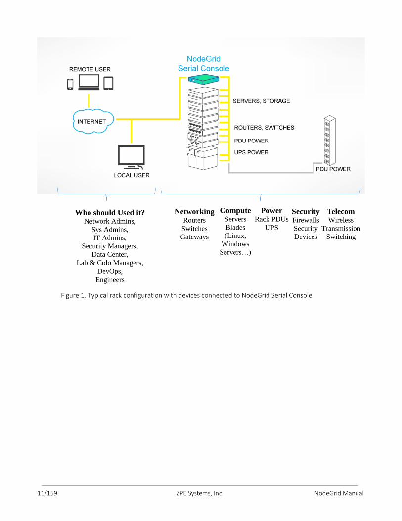
The following graphic illustrates a typical NodeGrid Serial Console T Series console server
configuration.
11/159 ZPE Systems, Inc. NodeGrid Manual
Figure 1. Typical rack configuration with devices connected to NodeGrid Serial Console
Who should Used it? Network Admins,
Sys Admins, IT Admins,
Security Managers, Data Center,
Lab & Colo Managers, DevOps, Engineers
Networking Routers
Switches Gateways
Compute Servers Blades (Linux,
Windows Servers…)
Power Rack PDUs
UPS
Security Firewalls Security Devices
Telecom Wireless
Transmission Switching
12/159 ZPE Systems, Inc. NodeGrid Manual
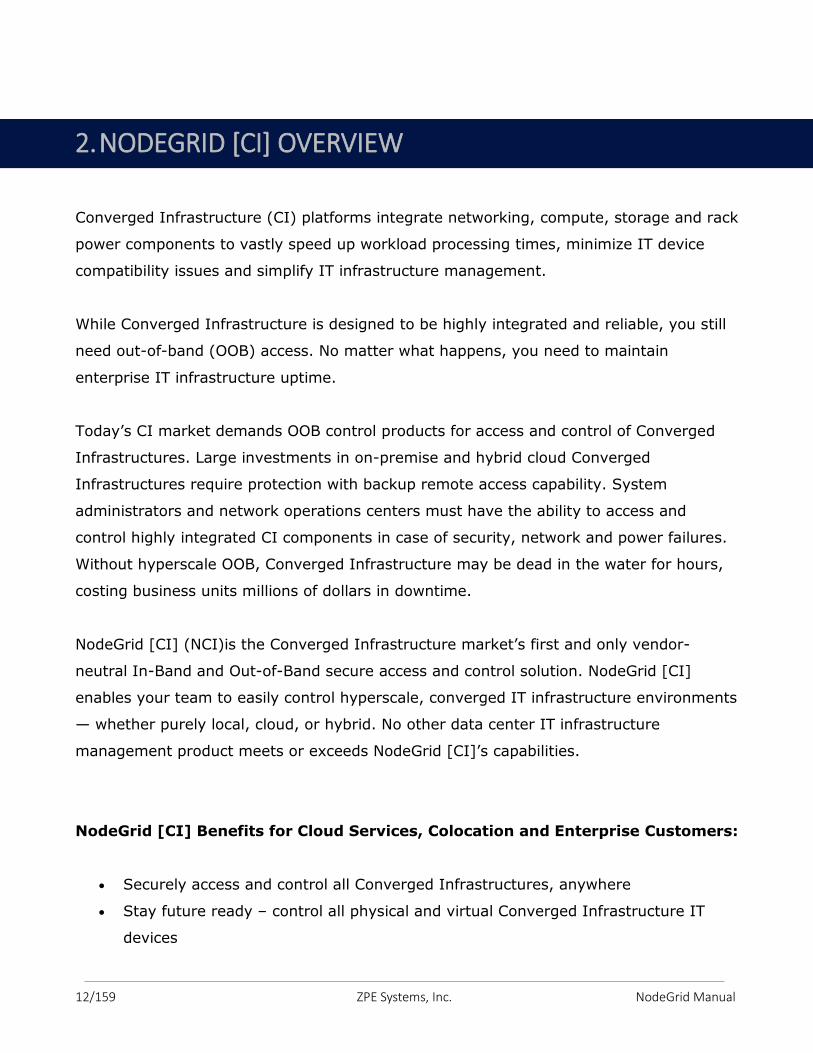
Converged Infrastructure (CI) platforms integrate networking, compute, storage and rack
power components to vastly speed up workload processing times, minimize IT device
compatibility issues and simplify IT infrastructure management.
While Converged Infrastructure is designed to be highly integrated and reliable, you still
need out-of-band (OOB) access. No matter what happens, you need to maintain
enterprise IT infrastructure uptime.
Today’s CI market demands OOB control products for access and control of Converged
Infrastructures. Large investments in on-premise and hybrid cloud Converged
Infrastructures require protection with backup remote access capability. System
administrators and network operations centers must have the ability to access and
control highly integrated CI components in case of security, network and power failures.
Without hyperscale OOB, Converged Infrastructure may be dead in the water for hours,
costing business units millions of dollars in downtime.
NodeGrid [CI] (NCI)is the Converged Infrastructure market’s first and only vendor-
neutral In-Band and Out-of-Band secure access and control solution. NodeGrid [CI]
enables your team to easily control hyperscale, converged IT infrastructure environments
— whether purely local, cloud, or hybrid. No other data center IT infrastructure
management product meets or exceeds NodeGrid [CI]’s capabilities.
NodeGrid [CI] Benefits for Cloud Services, Colocation and Enterprise Customers:
Securely access and control all Converged Infrastructures, anywhere
Stay future ready – control all physical and virtual Converged Infrastructure IT
devices
2. NODEGRID [CI] OVERVIEW
13/159 ZPE Systems, Inc. NodeGrid Manual
Save time on deployment and training costs with one control plane for all CI
platforms and protocols
Increase reliability and minimize MTTR, downtime and lost business productivity
with one easy to use/maintain solution
Reduce human error and increase efficiency via a vendor-neutral command set
Minimize headcount with one DevOps team for all Converged Infrastructures
Maintain flexibility with reliable industry standard hardware
Easily setup and deploy NodeGrid [CI] with Zero Touch Provisioning
Maintain high utilization with both Direct Linux shell access and a browser
dashboard
Docker and OpenStack optimized to further extend capabilities
Actionable real-time data and event logs
Reliably swaps to 4G/LTE modem in case of primary network outage
Industry first features: bare metal boot capabilities, system configuration security
checksum
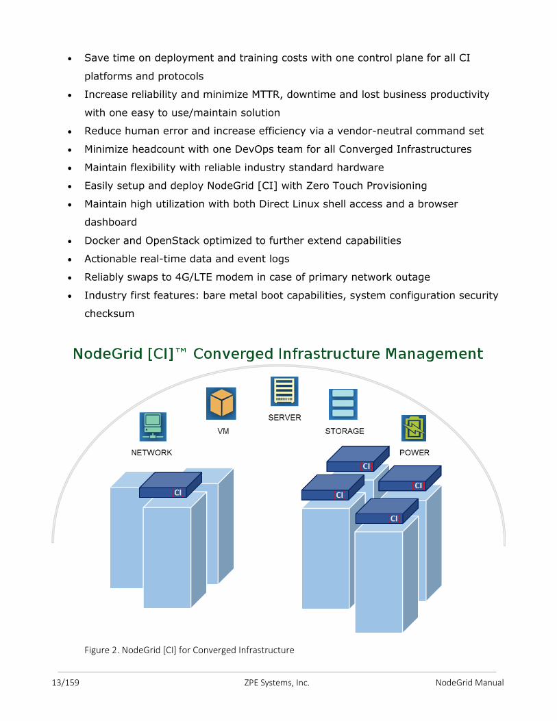
Figure 2. NodeGrid [CI] for Converged Infrastructure

14/159 ZPE Systems, Inc. NodeGrid Manual
This section of the NodeGrid Serial Console User Guide pertains to our NodeGrid Manager
console management software. A “lite” version of NodeGrid Manager drives the NodeGrid
Serial Console hardware appliance.
To see a demo or unlock the full features of NodeGrid Manager, contact a ZPE Support
Representative.
Figure 3. Example of managed devices views. Access managed devices by tree, table or map.
NodeGrid Manager (NGM) is a vendor neutral software-defined infrastructure virtual
appliance for access and control across of all devices in data centers and test lab
environments.
NodeGrid Manager’s core engine utilizes a technology stack that allows for policy based
automated discovery and configuration of your asset consoles to minimize configuration
and maintenance and utilizes a complete interface abstraction layer that implements the
many protocols and methods required to access and control your consoles from multiple
vendors.
NodeGrid's flexible console interface provides a complete Web interface and CLI (for
scripting) enabling complete customization and integration of your own console portals and
applications.
3. NODEGRID MANAGER OVERVIEW
15/159 ZPE Systems, Inc. NodeGrid Manual
3.1 NodeGrid Manager Features
Secure access and control of virtual and physical IT devices
DeviceURL™ bookmarks
NodeIQ™ elastic asset search
Cloud Clustering™ with horizontal and vertical scaling
FireTrail™ secure tunnel-through-firewall access
Shared Access with Console Data Logging
Service Processor Logging of Events and Sensors
Event notification and Alarms
Power Management
Auto-discovery of virtual and physical devices
Policy-based Authentication and Authorization via AD/LDAP
Web and CLI single interface
3.2 Supported Console Protocols
Service processors (iLO, DRAC, IPMI, CIMC/UCS, IMM, ILOM)
VMWare™ (Serial Console, MKS, vMotion™ migration tracking), KVM VMs (Serial
Console)
Legacy consoles (TELNET, SSH)
3.3 Benefits
Single screen access and control experience of physical and virtual assets
Quick and easy infrastructure deployment
Vendor neutral support for all console protocols
No need to maintain multiple vendors' admin tools
Save time with policy-based discovery and management
Keep firewalls secure
All in one. Installs from bootable ISO, no other software required.
Simplifies day-zero deployments
16/159 ZPE Systems, Inc. NodeGrid Manual
3.4 NodeGrid Manager System Requirements
NodeGrid Manager runs as a complete system solution on a Linux 64-bit host virtual
machine. The software is provided as a bootable ISO file. While NodeGrid Manager can
be installed in different virtualization environments, this installation document will
describe how to install it on a VMware ESXiTM server (minimum version ESXi 4.1). A client
workstation running VMware infrastructure client software (vSphereTM) is also required to
support the installation. The following are the minimum requirements for the virtual
machine in order to host NodeGrid Manager System:
8 GB hard drive space;
8 GB memory;
Network adapter;
Access to NodeGrid Manager ISO file.
For instructions on how to install NodeGrid Manager, refer to chapter 5.
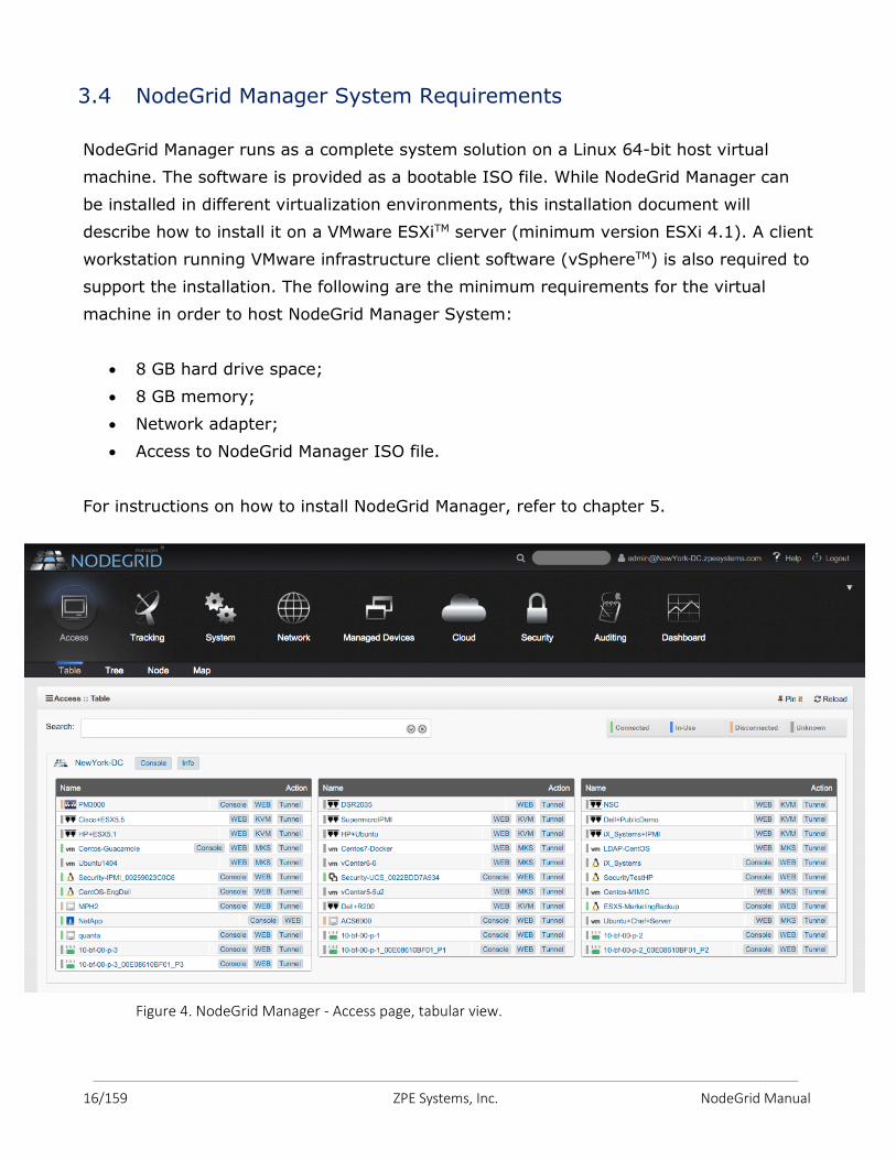
Figure 4. NodeGrid Manager - Access page, tabular view.
17/159 ZPE Systems, Inc. NodeGrid Manual
3.5 Access Options
NodeGrid Manager and Device access options:
Web browser (HTTPS or HTTP) for management session and device access.
The Web Manager can be used by the administrator to manage NodeGrid
Manager, access the device’s Web, launch CLI or Mouse-Keyboard-Screen
sessions (for VMware VMs and servers with service processor).
Supported browsers include: modern versions of Internet Explorer, Firefox and
Chrome.
CLI to NodeGrid Manager and device consoles via SSH v1, SSH v2 and Telnet,
including console of virtual appliances (VMware and KVM). CLI is ideal for
scripting or integration with other management and automation tools.
DeviceURL direct bookmark for fast access.
3.6 Authentication
NodeGrid Manager supports local authentication and remote authentication systems
including: Kerberos, LDAP, Radius, and Tacacs+. Once a configuration method is
selected, it will be used for authenticating any access to the system via Web, CLI and
console of the virtual machine running NodeGrid Manager, as well as serial sessions
(telnet or ssh) of the NodeGrid Serial Console.
3.7 Flexible Groups and Users
User accounts can be created locally on NodeGrid Manager or remotely on authentication
servers if remote authentication is selected. The admin user can add new user accounts
and create authorization groups in order to provide access rights to managed devices and
access profiles per user.
3.8 Managed Devices and Auto-discovery
The admin user can add managed devices following a variety of predefined profile types.
Each managed device requires a license from the license pool in order to be accessible.
18/159 ZPE Systems, Inc. NodeGrid Manual
NodeGrid Manager also supports device discovery. This feature allows newly discovered
devices to be cloned from existing devices matching their profile to build dynamic access
groups.
Note: each serial port of the NodeGrid Serial Console requires a license which is included
with the product.
3.9 Data Logging, Event Logging, Alerts and Notifications
NodeGrid Manager retains archives of data logging and event logging of managed devices
in local files or remotely via NFS. Logs can be used for inspection, compliance and
auditing purposes. Real-time alerts can be generated from data and event feeds
generated by the network or serial devices based on configurable regular expression
string. Notifications via Syslog, Email or SNMP trap can be used to alert administrators
about problems on managed devices or on NodeGrid Manager.
3.10 Security Services and Firewall
The user admin can enable and disable services, configure active ports, define firewall
rules, set session timeout per groups, define expiration dates for local user accounts and
require password renewal at login time. The admin can also create and configure Firewall
chains to control packet filtering. NodeGrid Manager ships with pre-defined built-in
Firewall chains for ease of use.
3.11 MKS, SOL, Virtual Serial, Physical Serial and Power
NodeGrid Manager offers a vendor neutral normalized console interface access for
managed devices via:
virtual serial console (for virtual appliances running on VMwareTM or KVM),
multi-vendor service processor SOL (serial over lan) console,
physical serial console port via multi-vendor console server appliances,
power via service processor, virtual machines or network PDUs.
19/159 ZPE Systems, Inc. NodeGrid Manual
It also supports Virtual Media and MKS (Mouse-Keyboard-Screen) for graphical UI of
VMwareTM virtual machines.
3.12 IPv4 and IPv6 Support
NodeGrid Manager supports single IPv4 stack or dual IPv4 and IPv6 stack (Note: NFS
supports IPv4 only). The following services are supported for IPv6:
HTTP / HTTPS access;
SSH and Telnet access;
Remote Authentication: Kerberos, Tacacs+, Radius and LDAP;
SNMP;
Linux Kernel;
Firewall (IP tables);
DHCP and Syslog server.
3.13 SNMP
SNMP v1, v2 and v3 are supported for the Enterprise MIB.
20/159 ZPE Systems, Inc. NodeGrid Manual
This chapter walks you through installation, configuration and operation.
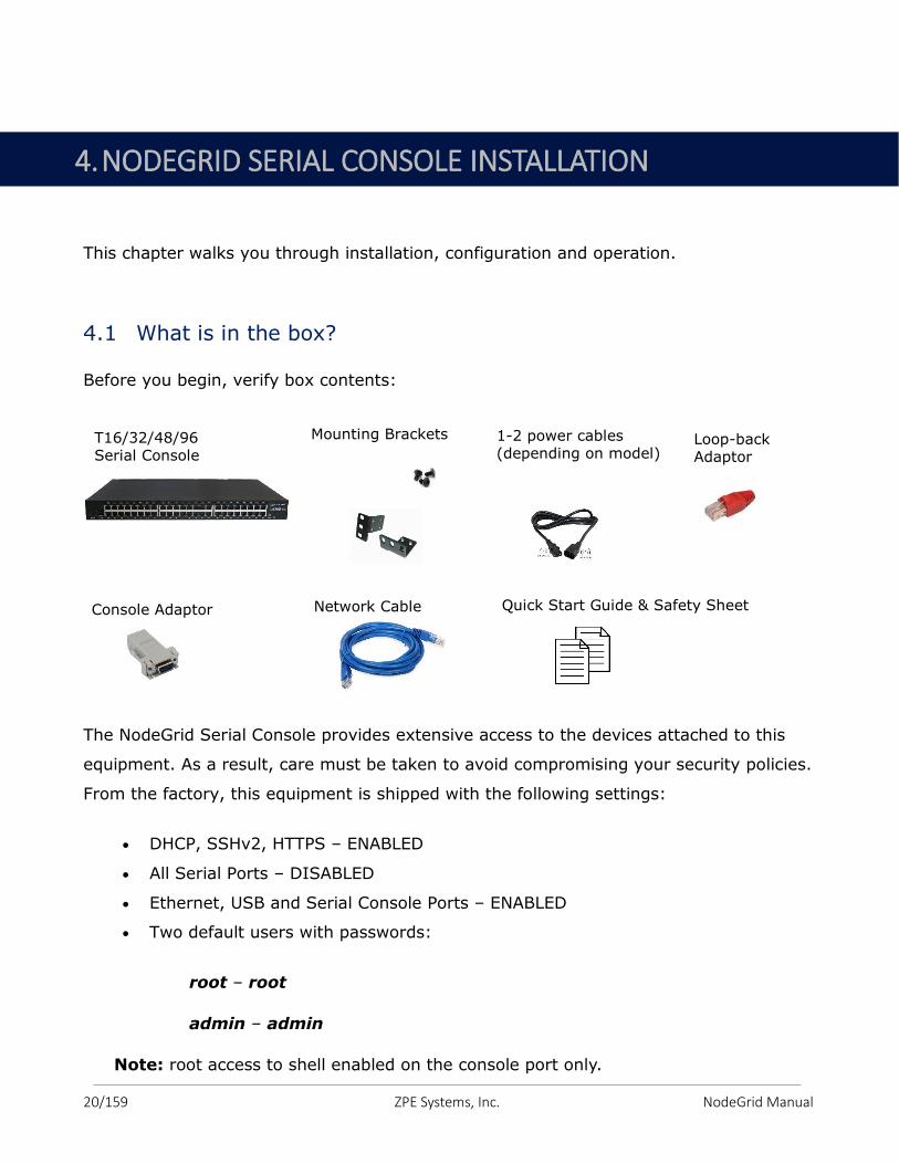
4.1 What is in the box?
Before you begin, verify box contents:
The NodeGrid Serial Console provides extensive access to the devices attached to this
equipment. As a result, care must be taken to avoid compromising your security policies.
From the factory, this equipment is shipped with the following settings:
DHCP, SSHv2, HTTPS – ENABLED
All Serial Ports – DISABLED
Ethernet, USB and Serial Console Ports – ENABLED
Two default users with passwords:
root – root
admin – admin
Note: root access to shell enabled on the console port only.
T16/32/48/96 Serial Console
Mounting Brackets 1-2 power cables (depending on model)
Console Adaptor Network Cable Quick Start Guide & Safety Sheet
Loop-back Adaptor
4. NODEGRID SERIAL CONSOLE INSTALLATION
21/159 ZPE Systems, Inc. NodeGrid Manual
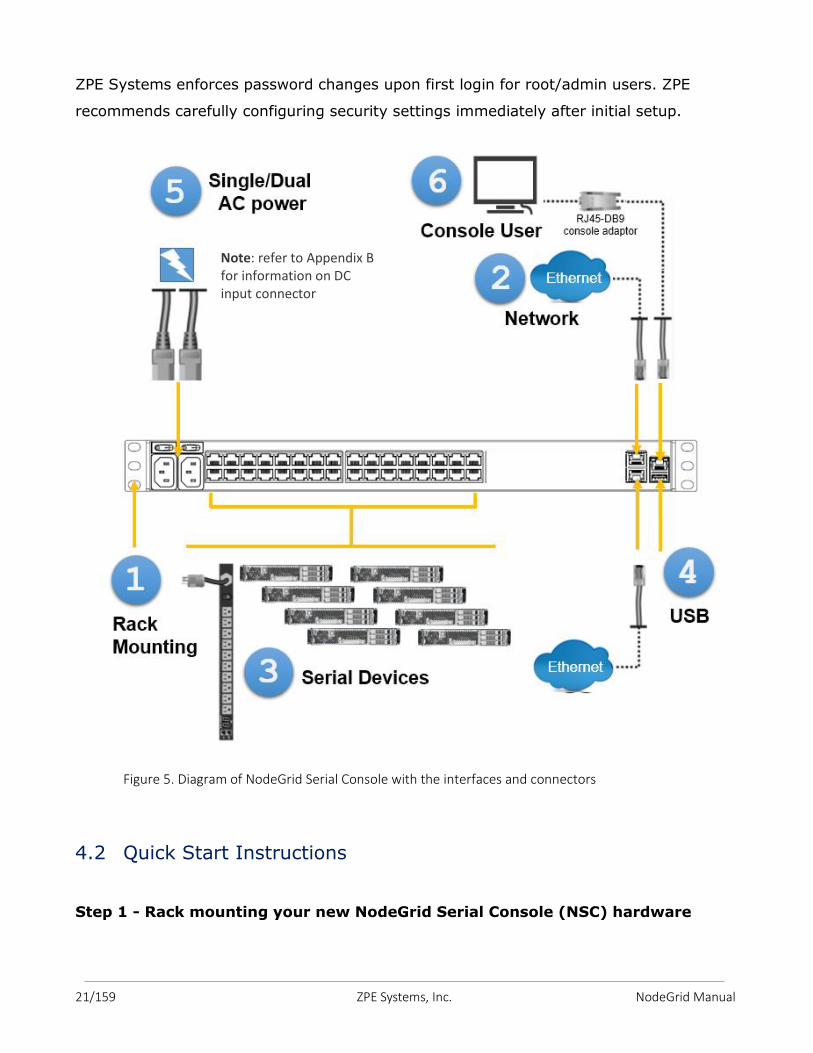
ZPE Systems enforces password changes upon first login for root/admin users. ZPE
recommends carefully configuring security settings immediately after initial setup.
Figure 5. Diagram of NodeGrid Serial Console with the interfaces and connectors
4.2 Quick Start Instructions
Step 1 - Rack mounting your new NodeGrid Serial Console (NSC) hardware
Note: refer to Appendix B for information on DC input connector
22/159 ZPE Systems, Inc. NodeGrid Manual
You can mount the NSC unit on two posts of a 19" rack or cabinet. Two rack mounting
brackets (RMK) are provided in the box. The remainder of this document will refer "rack
or cabinet" as "rack".
a. Install the rack mounting brackets with provided screws (5 for each bracket) to the
NSC for front-mount or back-mount (determine if you want the power cord(s) on
the front or on the back of the rack). See Figure 6.
b. Place your NSC unit to the allocated space in the rack.
c. Secure the unit by tightening the appropriate rack screws (not provided).
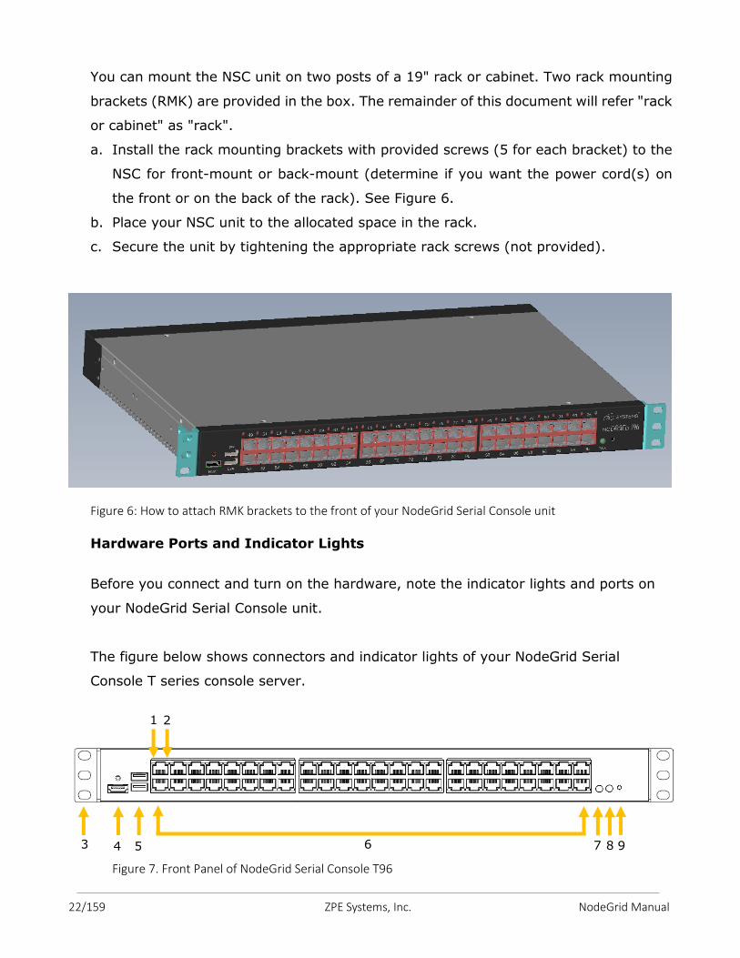
Figure 6: How to attach RMK brackets to the front of your NodeGrid Serial Console unit
Hardware Ports and Indicator Lights
Before you connect and turn on the hardware, note the indicator lights and ports on
your NodeGrid Serial Console unit.
The figure below shows connectors and indicator lights of your NodeGrid Serial
Console T series console server.
Figure 7. Front Panel of NodeGrid Serial Console T96
4 5 6 7 8 3
1 2
9
23/159 ZPE Systems, Inc. NodeGrid Manual
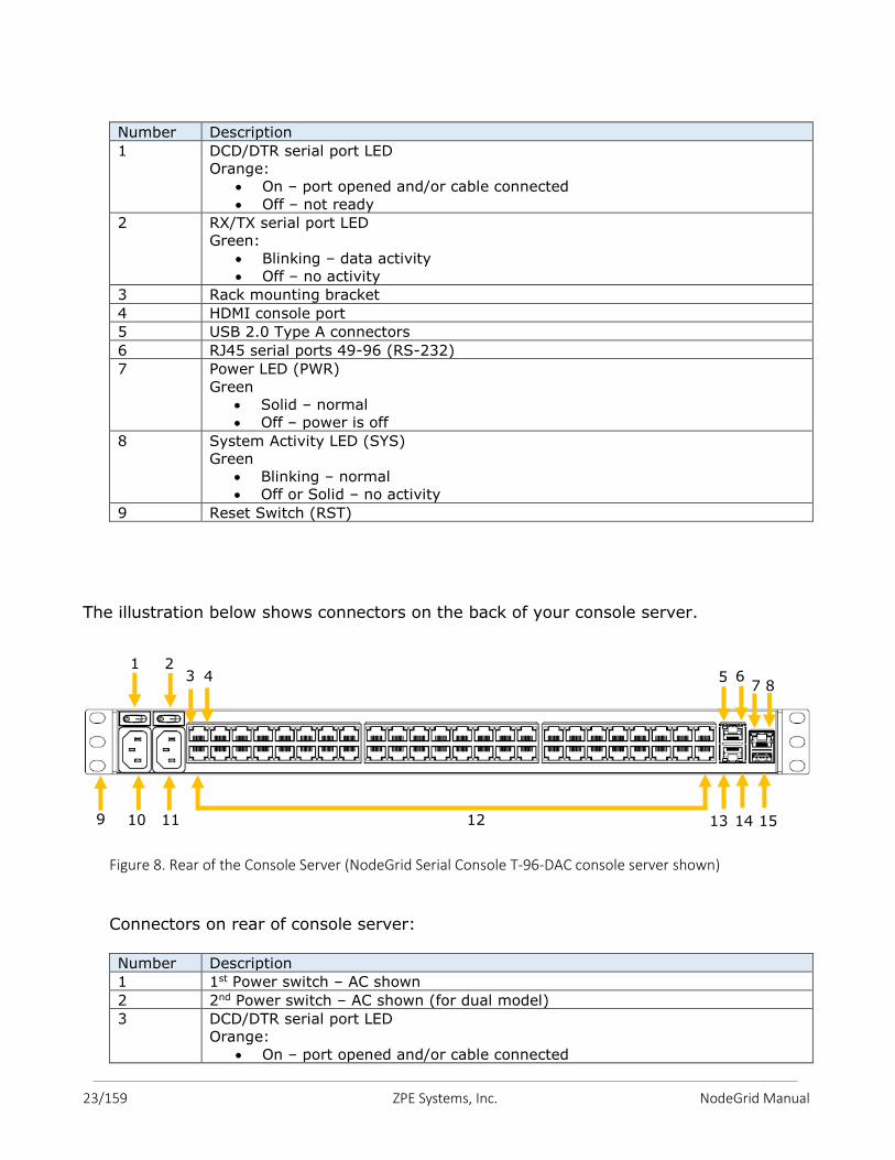
Number Description
1 DCD/DTR serial port LED
Orange:
On – port opened and/or cable connected
Off – not ready
2 RX/TX serial port LED
Green:
Blinking – data activity
Off – no activity
3 Rack mounting bracket
4 HDMI console port
5 USB 2.0 Type A connectors
6 RJ45 serial ports 49-96 (RS-232)
7 Power LED (PWR)
Green
Solid – normal
Off – power is off
8 System Activity LED (SYS)
Green
Blinking – normal
Off or Solid – no activity
9 Reset Switch (RST)
The illustration below shows connectors on the back of your console server.
Figure 8. Rear of the Console Server (NodeGrid Serial Console T-96-DAC console server shown)
Connectors on rear of console server: Number Description
1 1st Power switch – AC shown
2 2nd Power switch – AC shown (for dual model)
3 DCD/DTR serial port LED
Orange:
On – port opened and/or cable connected
1
\
2 5
6 7
9 10 11 12 13 14 15
3 4 8
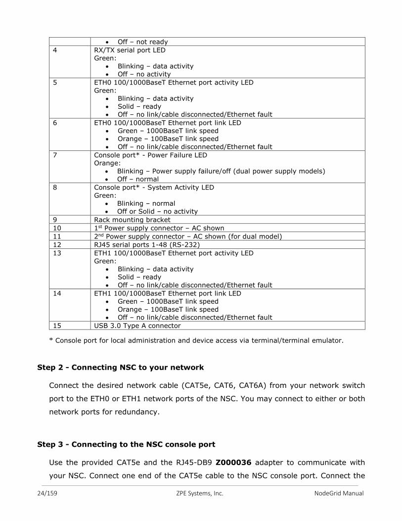
24/159 ZPE Systems, Inc. NodeGrid Manual
Off – not ready
4 RX/TX serial port LED
Green:
Blinking – data activity
Off – no activity
5 ETH0 100/1000BaseT Ethernet port activity LED
Green:
Blinking – data activity
Solid – ready
Off – no link/cable disconnected/Ethernet fault
6 ETH0 100/1000BaseT Ethernet port link LED
Green – 1000BaseT link speed
Orange – 100BaseT link speed
Off – no link/cable disconnected/Ethernet fault
7 Console port* - Power Failure LED
Orange:
Blinking – Power supply failure/off (dual power supply models)
Off – normal
8 Console port* - System Activity LED
Green:
Blinking – normal
Off or Solid – no activity
9 Rack mounting bracket
10 1st Power supply connector – AC shown
11 2nd Power supply connector – AC shown (for dual model)
12 RJ45 serial ports 1-48 (RS-232)
13 ETH1 100/1000BaseT Ethernet port activity LED
Green:
Blinking – data activity
Solid – ready
Off – no link/cable disconnected/Ethernet fault
14 ETH1 100/1000BaseT Ethernet port link LED
Green – 1000BaseT link speed
Orange – 100BaseT link speed
Off – no link/cable disconnected/Ethernet fault
15 USB 3.0 Type A connector
* Console port for local administration and device access via terminal/terminal emulator.
Step 2 - Connecting NSC to your network
Connect the desired network cable (CAT5e, CAT6, CAT6A) from your network switch
port to the ETH0 or ETH1 network ports of the NSC. You may connect to either or both
network ports for redundancy.
Step 3 - Connecting to the NSC console port
Use the provided CAT5e and the RJ45-DB9 Z000036 adapter to communicate with
your NSC. Connect one end of the CAT5e cable to the NSC console port. Connect the
25/159 ZPE Systems, Inc. NodeGrid Manual
other end to the RJ45-DB9 adapter, and then plug it to your laptop or PC's DB9 COM
port (if your laptop or PC does not have DB9 COM port, use a USB-DB9 adapter (not
provided)).
Have a serial application (such as xterm, Putty, SecureCRT) running on your laptop/PC
to open a terminal session to that COM port (see the system information about the COM
port to be used) with 115200bps, 8 bits, No parity, 1 stop bit, and no flow control
settings.
Step 4 - Connecting power cord(s) and powering on your NSC
Your NSC includes one or two AC power supplies, or two DC power supplies, depending
on your order. Connect power cord(s) to the NSC’s AC power supplies (See Appendix B
for information on the DC power supply ports).
Turn ON the NSC power switch(es).
Step 5 - Connecting Serial Devices to your NSC serial ports
Note: To comply with EMC requirements use shielded cables for all port connections.
The cabling and adapters that you may need to use between the NSC serial ports and
the serial devices’ console port will depend on their pinouts.
Latest serial devices such as routers, switches, and servers will have either a DB9
port or an RJ45 port as their console ports. See the manufacturer’s manual of your
serial device console port pinout. If RJ45, then most likely it will be a Cisco-like
pinout.
Depending on your NSC model, its serial ports will have either the Cyclades pinout or
the Cisco pinout. See tables 2 and 3 for the NSC serial port pinouts.
Caution! It is recommended to not power up connected serial devices until after the NodeGrid Serial Console is turned on.
26/159 ZPE Systems, Inc. NodeGrid Manual
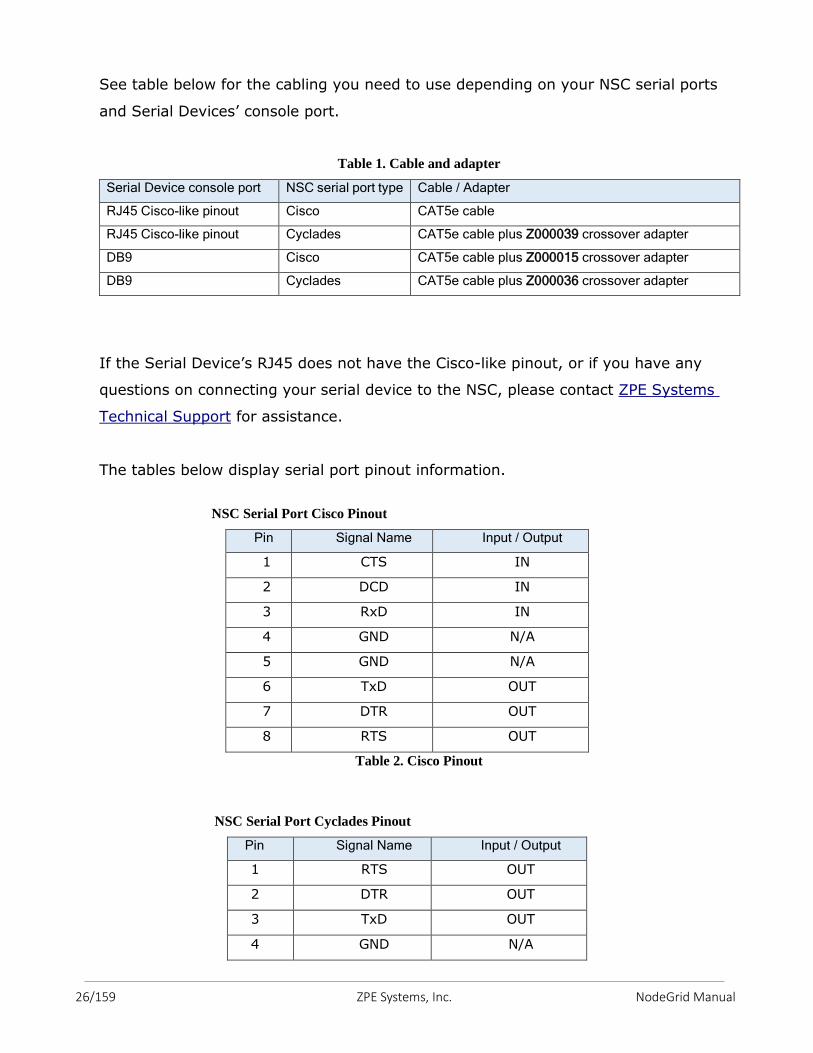
See table below for the cabling you need to use depending on your NSC serial ports
and Serial Devices’ console port.
Table 1. Cable and adapter
Serial Device console port NSC serial port type Cable / Adapter
RJ45 Cisco-like pinout Cisco CAT5e cable
RJ45 Cisco-like pinout Cyclades CAT5e cable plus Z000039 crossover adapter
DB9 Cisco CAT5e cable plus Z000015 crossover adapter
DB9 Cyclades CAT5e cable plus Z000036 crossover adapter
If the Serial Device’s RJ45 does not have the Cisco-like pinout, or if you have any
questions on connecting your serial device to the NSC, please contact ZPE Systems
Technical Support for assistance.
The tables below display serial port pinout information.
NSC Serial Port Cisco Pinout
Pin Signal Name Input / Output
1 CTS IN
2 DCD IN
3 RxD IN
4 GND N/A
5 GND N/A
6 TxD OUT
7 DTR OUT
8 RTS OUT
Table 2. Cisco Pinout
NSC Serial Port Cyclades Pinout
Pin Signal Name Input / Output
1 RTS OUT
2 DTR OUT
3 TxD OUT
4 GND N/A
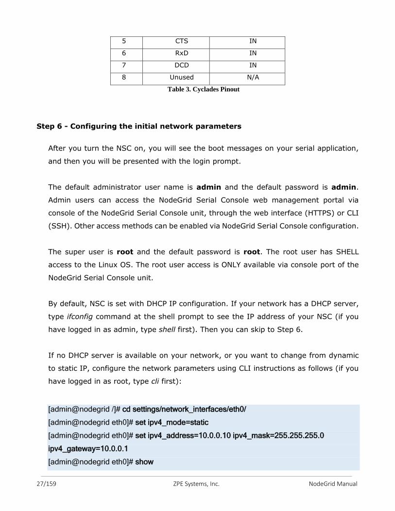
27/159 ZPE Systems, Inc. NodeGrid Manual
5 CTS IN
6 RxD IN
7 DCD IN
8 Unused N/A
Table 3. Cyclades Pinout
Step 6 - Configuring the initial network parameters
After you turn the NSC on, you will see the boot messages on your serial application,
and then you will be presented with the login prompt.
The default administrator user name is admin and the default password is admin.
Admin users can access the NodeGrid Serial Console web management portal via
console of the NodeGrid Serial Console unit, through the web interface (HTTPS) or CLI
(SSH). Other access methods can be enabled via NodeGrid Serial Console configuration.
The super user is root and the default password is root. The root user has SHELL
access to the Linux OS. The root user access is ONLY available via console port of the
NodeGrid Serial Console unit.
By default, NSC is set with DHCP IP configuration. If your network has a DHCP server,
type ifconfig command at the shell prompt to see the IP address of your NSC (if you
have logged in as admin, type shell first). Then you can skip to Step 6.
If no DHCP server is available on your network, or you want to change from dynamic
to static IP, configure the network parameters using CLI instructions as follows (if you
have logged in as root, type cli first):
[admin@nodegrid /]# cd settings/network_interfaces/eth0/
[admin@nodegrid eth0]# set ipv4_mode=static
[admin@nodegrid eth0]# set ipv4_address=10.0.0.10 ipv4_mask=255.255.255.0
ipv4_gateway=10.0.0.1
[admin@nodegrid eth0]# show
28/159 ZPE Systems, Inc. NodeGrid Manual
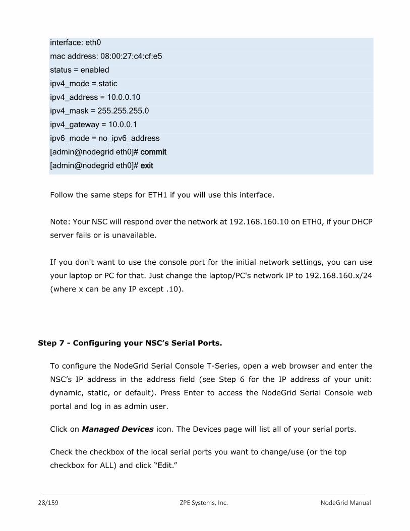
interface: eth0
mac address: 08:00:27:c4:cf:e5
status = enabled
ipv4_mode = static
ipv4_address = 10.0.0.10
ipv4_mask = 255.255.255.0
ipv4_gateway = 10.0.0.1
ipv6_mode = no_ipv6_address
[admin@nodegrid eth0]# commit
[admin@nodegrid eth0]# exit
Follow the same steps for ETH1 if you will use this interface.
Note: Your NSC will respond over the network at 192.168.160.10 on ETH0, if your DHCP
server fails or is unavailable.
If you don't want to use the console port for the initial network settings, you can use
your laptop or PC for that. Just change the laptop/PC's network IP to 192.168.160.x/24
(where x can be any IP except .10).
Step 7 - Configuring your NSC’s Serial Ports.
To configure the NodeGrid Serial Console T-Series, open a web browser and enter the
NSC’s IP address in the address field (see Step 6 for the IP address of your unit:
dynamic, static, or default). Press Enter to access the NodeGrid Serial Console web
portal and log in as admin user.
Click on Managed Devices icon. The Devices page will list all of your serial ports.
Check the checkbox of the local serial ports you want to change/use (or the top
checkbox for ALL) and click “Edit.”
29/159 ZPE Systems, Inc. NodeGrid Manual
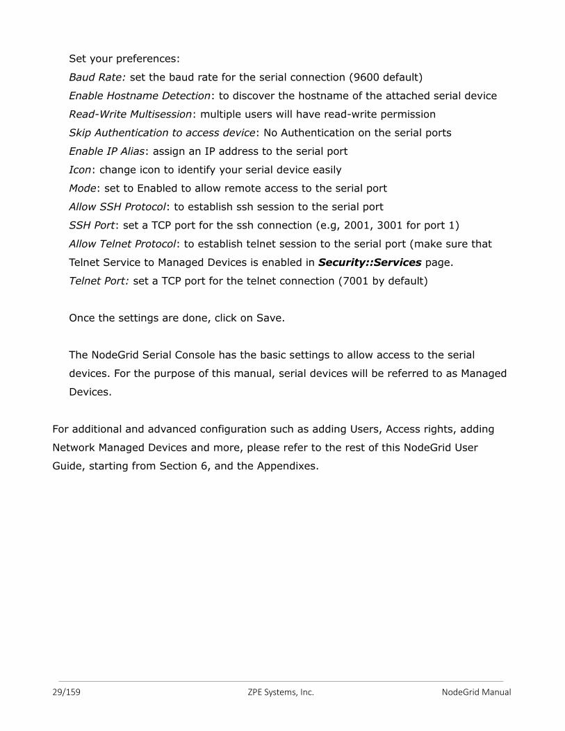
Set your preferences:
Baud Rate: set the baud rate for the serial connection (9600 default)
Enable Hostname Detection: to discover the hostname of the attached serial device
Read-Write Multisession: multiple users will have read-write permission
Skip Authentication to access device: No Authentication on the serial ports
Enable IP Alias: assign an IP address to the serial port
Icon: change icon to identify your serial device easily
Mode: set to Enabled to allow remote access to the serial port
Allow SSH Protocol: to establish ssh session to the serial port
SSH Port: set a TCP port for the ssh connection (e.g, 2001, 3001 for port 1)
Allow Telnet Protocol: to establish telnet session to the serial port (make sure that
Telnet Service to Managed Devices is enabled in Security::Services page.
Telnet Port: set a TCP port for the telnet connection (7001 by default)
Once the settings are done, click on Save.
The NodeGrid Serial Console has the basic settings to allow access to the serial
devices. For the purpose of this manual, serial devices will be referred to as Managed
Devices.
For additional and advanced configuration such as adding Users, Access rights, adding
Network Managed Devices and more, please refer to the rest of this NodeGrid User
Guide, starting from Section 6, and the Appendixes.
30/159 ZPE Systems, Inc. NodeGrid Manual
NodeGrid Serial Console and NodeGrid [CI] software come pre-installed on the
hardware.
NodeGrid Manager software is installed from an ISO file. The installation procedure is a three-stage process:
1. Creating a virtual machine;
2. Booting from the ISO file/CD in order to install the software;
3. Restarting and booting from the newly created virtual machine.
5.1 Creating a Virtual Machine
The following description is for a VMware environment. Similar procedures should be
executed for other hypervisors.
1. From the ESXi vSphere screen, click on Create a new virtual machine link;
2. For the virtual machine configuration, click on Typical and then click Next;
3. Choose an appropriate name for your NodeGrid Manager virtual machine and then,
click Next;
4. Select the data storage volume on which you wish to create for the new virtual
machine, then click Next;
5. Under Guest Operating System click on Linux and from the pull down menu select
Other Linux (64-bit), then click Next;
6. In the number of NICs field, type 1. Confirm if the network is a VM network and if
the adapter is flexible and then, click Next;
7. Confirm that the Disk size is (at least) 8 GB, select Thin Provision and then click
Next;
8. Click Finish to complete the configuration of the virtual machine on the ESXi
server.
5. NODEGRID MANAGER INSTALLATION & DEPLOYMENT
31/159 ZPE Systems, Inc. NodeGrid Manual
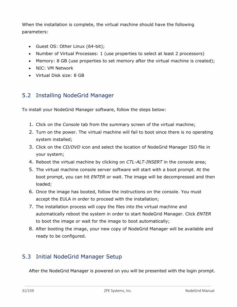
When the installation is complete, the virtual machine should have the following
parameters:
Guest OS: Other Linux (64-bit);
Number of Virtual Processes: 1 (use properties to select at least 2 processors)
Memory: 8 GB (use properties to set memory after the virtual machine is created);
NIC: VM Network
Virtual Disk size: 8 GB
5.2 Installing NodeGrid Manager
To install your NodeGrid Manager software, follow the steps below:
1. Click on the Console tab from the summary screen of the virtual machine;
2. Turn on the power. The virtual machine will fail to boot since there is no operating
system installed;
3. Click on the CD/DVD icon and select the location of NodeGrid Manager ISO file in
your system;
4. Reboot the virtual machine by clicking on CTL-ALT-INSERT in the console area;
5. The virtual machine console server software will start with a boot prompt. At the
boot prompt, you can hit ENTER or wait. The image will be decompressed and then
loaded;
6. Once the image has booted, follow the instructions on the console. You must
accept the EULA in order to proceed with the installation;
7. The installation process will copy the files into the virtual machine and
automatically reboot the system in order to start NodeGrid Manager. Click ENTER
to boot the image or wait for the image to boot automatically;
8. After booting the image, your new copy of NodeGrid Manager will be available and
ready to be configured.
5.3 Initial NodeGrid Manager Setup
After the NodeGrid Manager is powered on you will be presented with the login prompt.
32/159 ZPE Systems, Inc. NodeGrid Manual
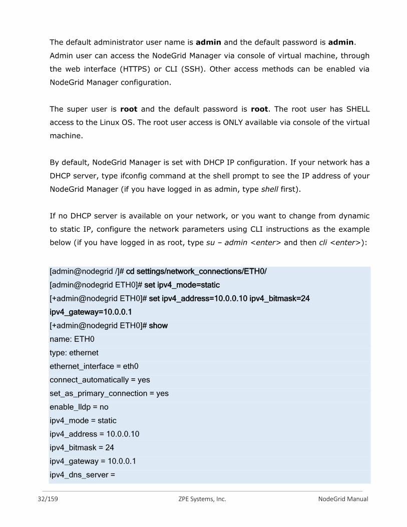
The default administrator user name is admin and the default password is admin.
Admin user can access the NodeGrid Manager via console of virtual machine, through
the web interface (HTTPS) or CLI (SSH). Other access methods can be enabled via
NodeGrid Manager configuration.
The super user is root and the default password is root. The root user has SHELL
access to the Linux OS. The root user access is ONLY available via console of the virtual
machine.
By default, NodeGrid Manager is set with DHCP IP configuration. If your network has a
DHCP server, type ifconfig command at the shell prompt to see the IP address of your
NodeGrid Manager (if you have logged in as admin, type shell first).
If no DHCP server is available on your network, or you want to change from dynamic
to static IP, configure the network parameters using CLI instructions as the example
below (if you have logged in as root, type su – admin <enter> and then cli <enter>):
[admin@nodegrid /]# cd settings/network_connections/ETH0/
[admin@nodegrid ETH0]# set ipv4_mode=static
[+admin@nodegrid ETH0]# set ipv4_address=10.0.0.10 ipv4_bitmask=24
ipv4_gateway=10.0.0.1
[+admin@nodegrid ETH0]# show
name: ETH0
type: ethernet
ethernet_interface = eth0
connect_automatically = yes
set_as_primary_connection = yes
enable_lldp = no
ipv4_mode = static
ipv4_address = 10.0.0.10
ipv4_bitmask = 24
ipv4_gateway = 10.0.0.1
ipv4_dns_server =
33/159 ZPE Systems, Inc. NodeGrid Manual
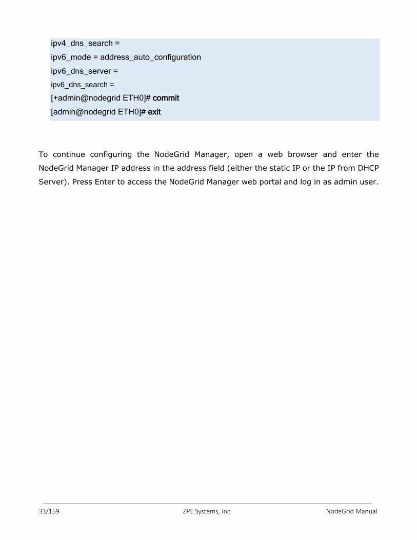
ipv4_dns_search =
ipv6_mode = address_auto_configuration
ipv6_dns_server =
ipv6_dns_search =
[+admin@nodegrid ETH0]# commit
[admin@nodegrid ETH0]# exit
To continue configuring the NodeGrid Manager, open a web browser and enter the
NodeGrid Manager IP address in the address field (either the static IP or the IP from DHCP
Server). Press Enter to access the NodeGrid Manager web portal and log in as admin user.
34/159 ZPE Systems, Inc. NodeGrid Manual
6.1 Web, SSH or Telnet
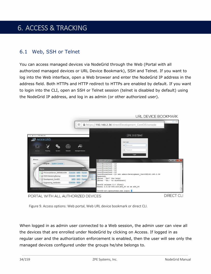
You can access managed devices via NodeGrid through the Web (Portal with all
authorized managed devices or URL Device Bookmark), SSH and Telnet. If you want to
log into the Web interface, open a Web browser and enter the NodeGrid IP address in the
address field. Both HTTPs and HTTP redirect to HTTPs are enabled by default. If you want
to login into the CLI, open an SSH or Telnet session (telnet is disabled by default) using
the NodeGrid IP address, and log in as admin (or other authorized user).
Figure 9. Access options: Web portal, Web URL device bookmark or direct CLI.
When logged in as admin user connected to a Web session, the admin user can view all
the devices that are enrolled under NodeGrid by clicking on Access. If logged in as
regular user and the authorization enforcement is enabled, then the user will see only the
managed devices configured under the groups he/she belongs to.
6. ACCESS & TRACKING
35/159 ZPE Systems, Inc. NodeGrid Manual
In order to view the devices and connect to a managed device via Web session, follow
the steps below:
1. Click on Access on the top navigation. A list of names or aliases for all configured
and installed devices which the user is authorized to access, will be displayed on
the content area;
2. In the Action Column, select Console and an HTML5 viewer will start. On the top of
the viewer window you will see the name of the managed device you are
connected to.
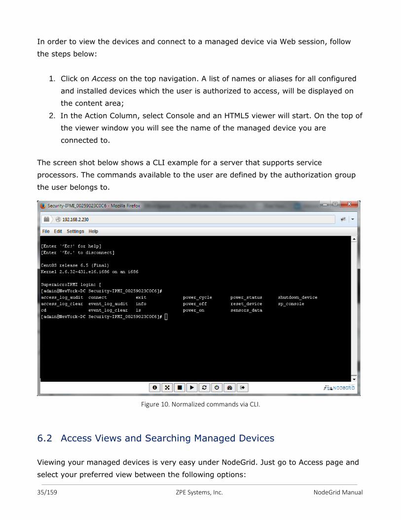
The screen shot below shows a CLI example for a server that supports service
processors. The commands available to the user are defined by the authorization group
the user belongs to.
Figure 10. Normalized commands via CLI.
6.2 Access Views and Searching Managed Devices
Viewing your managed devices is very easy under NodeGrid. Just go to Access page and
select your preferred view between the following options:
36/159 ZPE Systems, Inc. NodeGrid Manual
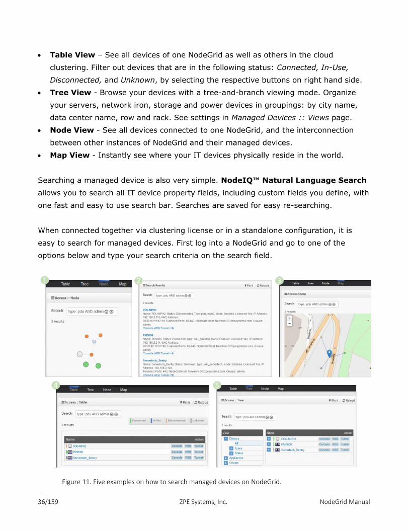
Table View – See all devices of one NodeGrid as well as others in the cloud
clustering. Filter out devices that are in the following status: Connected, In-Use,
Disconnected, and Unknown, by selecting the respective buttons on right hand side.
Tree View - Browse your devices with a tree-and-branch viewing mode. Organize
your servers, network iron, storage and power devices in groupings: by city name,
data center name, row and rack. See settings in Managed Devices :: Views page.
Node View - See all devices connected to one NodeGrid, and the interconnection
between other instances of NodeGrid and their managed devices.
Map View - Instantly see where your IT devices physically reside in the world.
Searching a managed device is also very simple. NodeIQ™ Natural Language Search
allows you to search all IT device property fields, including custom fields you define, with
one fast and easy to use search bar. Searches are saved for easy re-searching.
When connected together via clustering license or in a standalone configuration, it is
easy to search for managed devices. First log into a NodeGrid and go to one of the
options below and type your search criteria on the search field.
Figure 11. Five examples on how to search managed devices on NodeGrid.
37/159 ZPE Systems, Inc. NodeGrid Manual
The NodeGrid platform is dynamically in sync with your environment. Newly added
devices are automatically discovered, indexed and immediately available to authorized
users and over the clustering configuration.
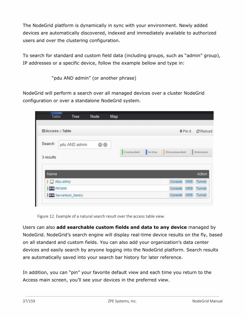
To search for standard and custom field data (including groups, such as “admin” group),
IP addresses or a specific device, follow the example bellow and type in:
“pdu AND admin” (or another phrase)
NodeGrid will perform a search over all managed devices over a cluster NodeGrid
configuration or over a standalone NodeGrid system.
Figure 12. Example of a natural search result over the access table view.
Users can also add searchable custom fields and data to any device managed by
NodeGrid. NodeGrid’s search engine will display real-time device results on the fly, based
on all standard and custom fields. You can also add your organization’s data center
devices and easily search by anyone logging into the NodeGrid platform. Search results
are automatically saved into your search bar history for later reference.
In addition, you can “pin” your favorite default view and each time you return to the
Access main screen, you’ll see your devices in the preferred view.
38/159 ZPE Systems, Inc. NodeGrid Manual
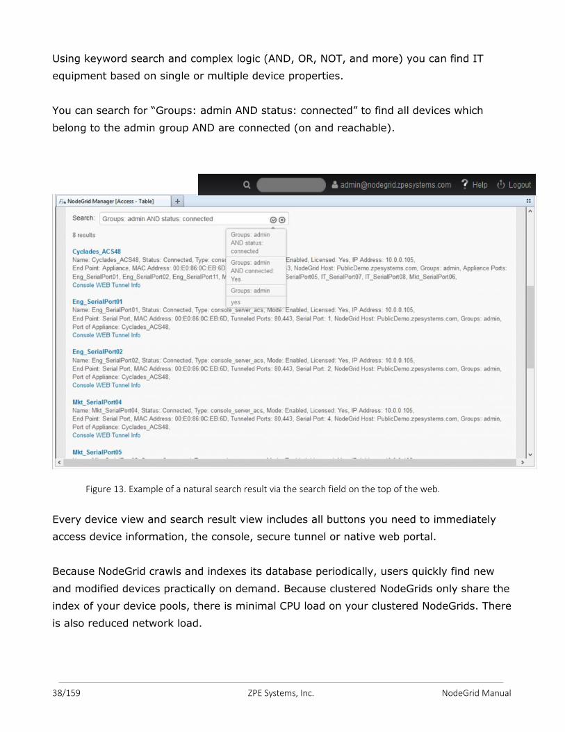
Using keyword search and complex logic (AND, OR, NOT, and more) you can find IT
equipment based on single or multiple device properties.
You can search for “Groups: admin AND status: connected” to find all devices which
belong to the admin group AND are connected (on and reachable).
Figure 13. Example of a natural search result via the search field on the top of the web.
Every device view and search result view includes all buttons you need to immediately
access device information, the console, secure tunnel or native web portal.
Because NodeGrid crawls and indexes its database periodically, users quickly find new
and modified devices practically on demand. Because clustered NodeGrids only share the
index of your device pools, there is minimal CPU load on your clustered NodeGrids. There
is also reduced network load.
39/159 ZPE Systems, Inc. NodeGrid Manual
6.3 Accessing the Managed Devices and Serial Devices via Telnet or
SSH
Note: by default, Telnet access is turned off with your NodeGrid Managed Devices.
Authorized users can use Telnet or SSH to connect directly to the console of a
managed device if all of the following are true:
Telnet / SSH protocol is enabled under Security
Telnet / SSH protocol is configured for the port
Telnet / SSH client available and enabled on the computer from which you are
opening a connection
6.3.1 How to Telnet to a Managed Devices
To connect successfully to the Managed Devices, you need:
the hostname (i.e, SFO-DC7-R33-NSCT96) or IP address (i.e, 110.0.0.200) of the
NSC
a username configured to access the managed device. (or none, if authentication
on the serial port is skipped)
either the Device Name (i.e., SFO-DC7-R33-P3), Port name (i.e., ttyS3), TCP Port
(i.e., 7003) or IP port alias (i.e., 110.0.0.10).
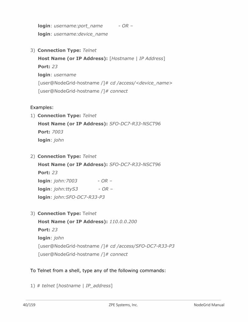
To use a Telnet client, such as Putty, type the above information into client.
1) Connection Type: Telnet
Host Name (or IP Address): [Hostname | IP Address]
Port: [TCP_Port_Alias]
login: username
2) Connection Type: Telnet
Host Name (or IP Address): [Hostname | IP Address]
Port: 23
login: username:TCP_Port_Alias - OR –
40/159 ZPE Systems, Inc. NodeGrid Manual
login: username:port_name - OR –
login: username:device_name
3) Connection Type: Telnet
Host Name (or IP Address): [Hostname | IP Address]
Port: 23
login: username
[user@NodeGrid-hostname /]# cd /access/<device_name>
[user@NodeGrid-hostname /]# connect
Examples:
1) Connection Type: Telnet
Host Name (or IP Address): SFO-DC7-R33-NSCT96
Port: 7003
login: john
2) Connection Type: Telnet
Host Name (or IP Address): SFO-DC7-R33-NSCT96
Port: 23
login: john:7003 - OR –
login: john:ttyS3 - OR –
login: john:SFO-DC7-R33-P3
3) Connection Type: Telnet
Host Name (or IP Address): 110.0.0.200
Port: 23
login: john
[user@NodeGrid-hostname /]# cd /access/SFO-DC7-R33-P3
[user@NodeGrid-hostname /]# connect
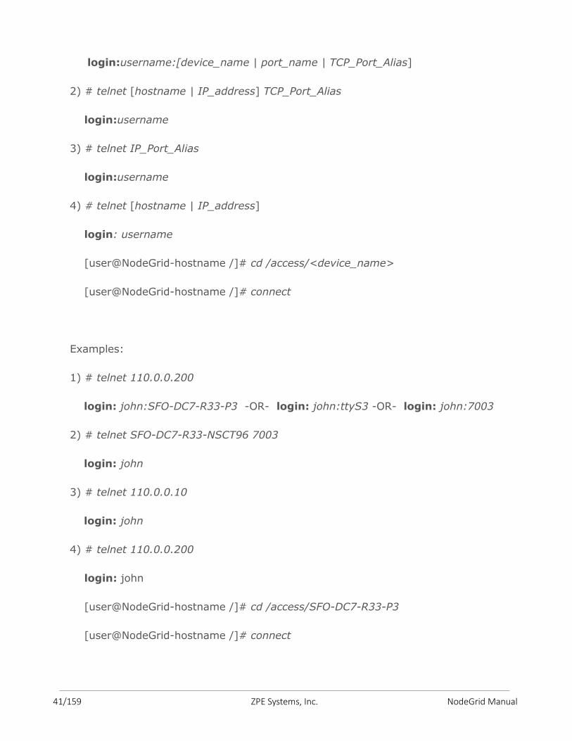
To Telnet from a shell, type any of the following commands:
1) # telnet [hostname | IP_address]
41/159 ZPE Systems, Inc. NodeGrid Manual
login:username:[device_name | port_name | TCP_Port_Alias]
2) # telnet [hostname | IP_address] TCP_Port_Alias
login:username
3) # telnet IP_Port_Alias
login:username
4) # telnet [hostname | IP_address]
login: username
[user@NodeGrid-hostname /]# cd /access/<device_name>
[user@NodeGrid-hostname /]# connect
Examples:
1) # telnet 110.0.0.200
login: john:SFO-DC7-R33-P3 -OR- login: john:ttyS3 -OR- login: john:7003
2) # telnet SFO-DC7-R33-NSCT96 7003
login: john
3) # telnet 110.0.0.10
login: john
4) # telnet 110.0.0.200
login: john
[user@NodeGrid-hostname /]# cd /access/SFO-DC7-R33-P3
[user@NodeGrid-hostname /]# connect
42/159 ZPE Systems, Inc. NodeGrid Manual
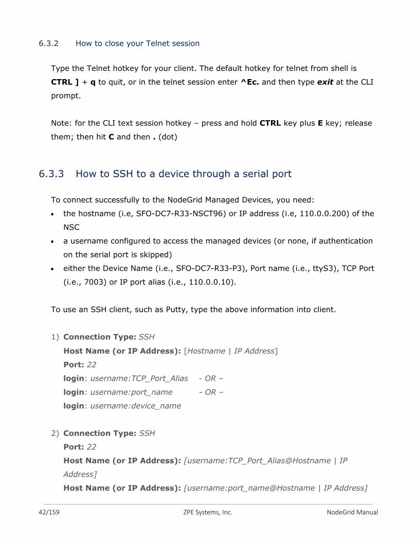
6.3.2 How to close your Telnet session
Type the Telnet hotkey for your client. The default hotkey for telnet from shell is
CTRL ] + q to quit, or in the telnet session enter ^Ec. and then type exit at the CLI
prompt.
Note: for the CLI text session hotkey – press and hold CTRL key plus E key; release
them; then hit C and then . (dot)
6.3.3 How to SSH to a device through a serial port
To connect successfully to the NodeGrid Managed Devices, you need:
the hostname (i.e, SFO-DC7-R33-NSCT96) or IP address (i.e, 110.0.0.200) of the
NSC
a username configured to access the managed devices (or none, if authentication
on the serial port is skipped)
either the Device Name (i.e., SFO-DC7-R33-P3), Port name (i.e., ttyS3), TCP Port
(i.e., 7003) or IP port alias (i.e., 110.0.0.10).
To use an SSH client, such as Putty, type the above information into client.
1) Connection Type: SSH
Host Name (or IP Address): [Hostname | IP Address]
Port: 22
login: username:TCP_Port_Alias - OR –
login: username:port_name - OR –
login: username:device_name
2) Connection Type: SSH
Port: 22
Host Name (or IP Address): [username:TCP_Port_Alias@Hostname | IP
Address]
Host Name (or IP Address): [username:port_name@Hostname | IP Address]
43/159 ZPE Systems, Inc. NodeGrid Manual
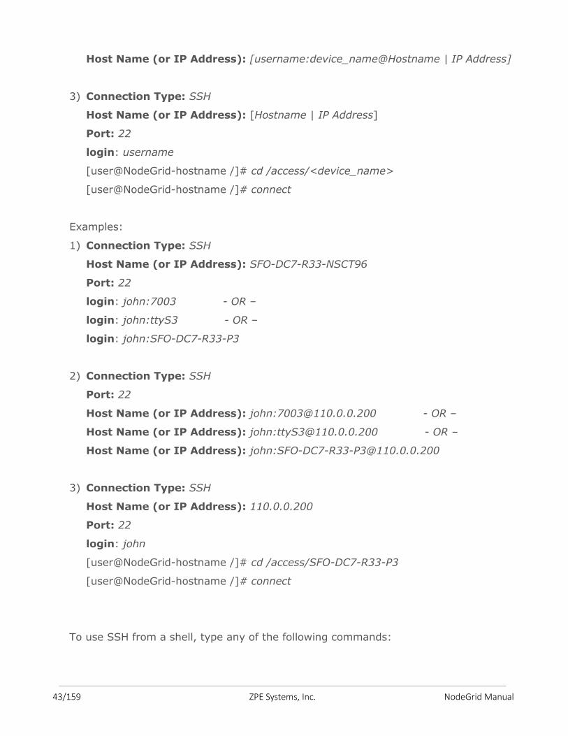
Host Name (or IP Address): [username:device_name@Hostname | IP Address]
3) Connection Type: SSH
Host Name (or IP Address): [Hostname | IP Address]
Port: 22
login: username
[user@NodeGrid-hostname /]# cd /access/<device_name>
[user@NodeGrid-hostname /]# connect
Examples:
1) Connection Type: SSH
Host Name (or IP Address): SFO-DC7-R33-NSCT96
Port: 22
login: john:7003 - OR –
login: john:ttyS3 - OR –
login: john:SFO-DC7-R33-P3
2) Connection Type: SSH
Port: 22
Host Name (or IP Address): john:[email protected] - OR –
Host Name (or IP Address): john:[email protected] - OR –
Host Name (or IP Address): john:[email protected]
3) Connection Type: SSH
Host Name (or IP Address): 110.0.0.200
Port: 22
login: john
[user@NodeGrid-hostname /]# cd /access/SFO-DC7-R33-P3
[user@NodeGrid-hostname /]# connect
To use SSH from a shell, type any of the following commands:
44/159 ZPE Systems, Inc. NodeGrid Manual
1) # ssh –l username:port_name [hostname | IP_address]
2) # ssh –l username:device_name [hostname | IP_address]
3) # ssh –l username:TCP_Port_Alias [hostname | IP_address]
4) # ssh –l username IP_Port_Alias
5) # ssh –l username [hostname | IP_address]
[user@NodeGrid-hostname /]# cd /access/<device_name>
[user@NodeGrid-hostname /]# connect
Examples:
1) # ssh –l john:SFO-DC7-R33-P3 SFO-DC7-R33-NSCT96
2) # ssh –l john:ttyS3 110.0.0.200
3) # ssh –l john:7003 SFO-DC7-R33-NSCT96
4) # ssh –l john 110.0.0.10
5) # ssh –l john 110.0.0.200
[user@NodeGrid-hostname /]# cd /access/SFO-DC7-R33-P3
[user@NodeGrid-hostname /]# connect
6.3.4 How to close your SSH Session
At the beginning of new a line (hit ENTER), type the hotkey defined for the SSH from
a shell followed by a dot. The default hotkey is ~. (tilde dot)
Or, enter ^Ec. and then type exit at the CLI prompt.
Note: for the CLI text session hotkey – press and hold CTRL key plus E key; release
them; then hit C and then . (dot)
6.4 Tracking
The Tracking page provides information on Open Sessions, Event List, Routing Table,
System Usage, Discovery Logs, and LLDP (NodeGrid Serial Console has additionally,
Serial Statistics).
45/159 ZPE Systems, Inc. NodeGrid Manual
The Open Sessions page shows all users actively connected to the system, from where
they are connecting from, and for how long. If a user has permission based on an
authorization group, he/she can terminate sessions.
The Event List page provides a statistical information on the system events occurrences.
You may select the events and reset the counters.
The Routing Table page shows the routing rules that NodeGrid follows for the network
communications. It also included any static routes added in Networks :: Static Routes.
The System Usage page presents Memory, CPU, and Disk usages.
The Discovery Logs page shows the logs of the discovery processes set on the Managed
Devices’ setting for auto discovery.
The LLDP page shows the devices that are advertising their identity and capabilities on
the LAN. You may want to enable LLDP advertising and reception through this connection
in your NodeGrid by setting it up in Networks :: Connections :: ETH0 or ETH1.
The Serial Statistics page (in NodeGrid Serial Console) provides a statistical information
on the serial ports connectivity such as transmitted and received data, RS232 signals,
errors.
46/159 ZPE Systems, Inc. NodeGrid Manual
The system menu options are as following:
7.1 License
Select this option to view license information for NodeGrid. Enrolled licenses will show on
this table along with detailed information about the number of managed licenses and any
other relevant information. Multiple licenses can be added on the system. For licenses of
the same type, the total number of allowed managed devices will be the sum of all
licenses up to upper limit supported by the system (currently 1,000 nodes). Excess
devices beyond this limit will not be supported. The top right corner of this content page
shows a summary of the licenses installed, in use and available. Click on Add if you want
to add a license and then, in the license field, enter the key of the license you are
adding. If you want to delete a license, click on its respective box and then click on
Delete.
Configuring via CLI
Type the following commands to add license to NodeGrid:
[admin@nodegrid /]# add /settings/license/
[admin@nodegrid {license}]# set license_key=XXXXX-XXXXX-XXXXX-XXXXX
[admin@nodegrid {license}]# commit
7.2 Preferences
This page allows the user to configure system’s parameters. The following fields are
relevant for this page:
Address Location is a free format field for the address location of NodeGrid. Once you
enter the physical address, the option for Coordinates will be made available.
Online help allows the user to define an alternate location where the user manual can
be posted. When the user clicks on the Help button on the top right corner of the Web
interface, a new Web page opens up and the file defined on this URL location is
7. SYSTEM
47/159 ZPE Systems, Inc. NodeGrid Manual
shown. The default location of the manual can be changed. For example: the
administrator can download the file and post the manual in any other location of the
network that is reachable by NodeGrid.
Session Timeout allows the admin user to configure the number of minutes before
open idle sessions are timed out due to inactivity. Configuration changes on this field
will be effective for new sessions only. Existing sessions will continue following their
session timeout value specified during their login time. A zero in this field allows new
sessions to never expire. This setting applies to all telnet, ssh, http, https, and
console sessions.
Login Page Logo allows transferring a new image to NodeGrid, which will be used on
the Web login page. You must refresh your browser cache in order to see the new
image. The image file (extensions: .png or .jpg) can be transferred from the local
computer or from a remote server (FTP, TFTP, SFTP, SCP, HTTP, and HTTPS in the
URL format: <PROTOCOL>://<ServerAddress>/<Remote File>).
Select default logo image to restore the default image.
Login Banner allows the system to show a common message during the login process.
The message will be shown on Telnet, SSH, HTTP, HTTPs and Console. This is typically
used to show warning messages before the user logs in on the system. The admin
user can edit and customize the default message.
Network Boot allows the admin user to set the NodeGrid’s network boot configuration
so that it can get the ISO file from the network in case the local ISO file gets
corrupted or damaged, for some reason.
Utilization Rate Events allows the admin user to enable utilization rate of license and
trigger events when it reaches the percentage you specify in the field (by default it is
90).
For NodeGrid Serial Console only:
Utilization Rate Events option to enable utilization rate of local serial ports
Serial Console allows admin user to set the baud rate of the local console port
(default: 115200bps).
Dual Power Supply allows admin user to enable or disable the alarm sound in case
one the power supplies is not on (for DAC models).
Note: In case it is enabled and one of the power supplies is off, the admin user has
the option to acknowledge its state by hitting the Acknowledge Power Supply State
button on top of the page.
48/159 ZPE Systems, Inc. NodeGrid Manual
7.3 Date and Time
The date and time can be retrieved from a Network Time Protocol (NTP) server or be set
manually. NTP is the default configuration for this option and it will try to retrieve the
date and time from any server in the NTP pool. In manual configuration mode, NodeGrid
will use its own clock to provide date and time information. The user must refresh this
page to see current system time.
The admin user can also set the time zone of choice from the drop down menu options.
Note: all timestamp of Event Logs is in UTC.
7.4 Toolkit
Use this option to Reboot, Shutdown, Software Upgrade, Save Settings (to backup
settings), Apply Settings (to restore settings), Restore to Factory Default Settings
(erase and recover original installation settings), System Certificates, and System
Configuration Checksum.
When selecting Remote Server, enter the server and filename information in the URL
Format: <PROTOCOL>://<ServerAddress>/<Remote File> along with the username and password.
Software Upgrade, Apply Settings, and System Certificate support the following
protocols: FTP, TFTP, SFTP, SCP, HTTP, and HTTPS.
Save Settings supports these protocols: FTP, TFTP, SFTP, and SCP.
Remote File should have the file path and the filename.
ServerAddress can be the IP address or hostname/FQDN. If IP address is an IPv6, it
should be between brackets [ ].
Examples:
URL: ftp://192.168.2.201/downloads/NodeGrid_Platform_v3.1.0_20160128.iso
URL: scp://192.168.2.210/tmp/nodegrid.config
49/159 ZPE Systems, Inc. NodeGrid Manual
7.5 Logging
Use this option to enable data logging collection of CLI sessions. If this selection is
enabled, all data exchange during a CLI session will be logged for auditing and
inspection. The admin user can inspect and clear data logs via the CLI command.
7.6 Custom Fields
Use this selection to add searchable custom fields and value to NodeGrid system. Data
entered here will be displayed in NodeGrid Info in Access page.
50/159 ZPE Systems, Inc. NodeGrid Manual
The network menu options are as follows:
8.1 Settings
Use this selection to configure the Hostname and Domain Name for NodeGrid, to enable
Network FailOver and Dynamic DNS, and to enable IPv4 IP Forward and Disable IPv6.
Once Dynamic DNS is enabled, configured, and saved, you can click on Show DDNS
Public Key button to display the public key.
8.2 Connections
This page will list all the available Ethernet interfaces on NodeGrid. The NodeGrid
Manager can have up to 4 Ethernet interfaces. The Ethernet interfaces must be created
by the hypervisor management system, and once they are available, the admin user can
add them onto NodeGrid Manager. On the NodeGrid Serial Console and [CI], 2 native
Ethernet interfaces, ETH0 and ETH1, and 1 WiFi interface, HotSpot, are presented by
default. Admin user also can delete, bring up or down the connections.
Caution: be careful when selecting the Delete and Down Connection options as you will
lose remote connection to the NodeGrid.
Configure the interfaces for additional IPv4 and IPv6 parameters, and set IPv4 and IPv6
DNS Server and Search configuration by clicking on the name of the interface.
Admin user can select to have the interface to Connect Automatically, to Set as Primary
Connection, and to Enable LLDP advertising and reception through this connection.
The NodeGrid Serial Console is WiFi Hostpot Ready. Just insert your WiFi Hotspot USB
device to the NSC, and then configure the WiFi interface. Enter the WiFi SSID and have
the WiFi Security as Disabled or WPA2 Personal with its WPA Shared Key, according to
the USB WiFi device.
8. NETWORK
51/159 ZPE Systems, Inc. NodeGrid Manual
Select one of the IPv4 mode options below:
No IPv4 address to disable IPv4.
DHCP if you want to have the IPv4 address set by the DHCP server;
Static, to enter the IPv4 IP address, bitmask and default gateway manually.
Select one of the IPv6 mode options below:
No IPv6 address to disable IPv6.
Address Auto Configuration if the link is restricted to the local IP address
(Stateless);
Stateful DHCPv6 if you want to have the IPv6 IP address set by the IPv6 DHCP
server;
Static to enter the IPv6 IP address, prefix length, and default gateway manually;
Note: In order to support IPv6, enable it under Network :: Settings.
8.3 Static Routes
This page allows the admin user to create IPv4 and IPv6 static routes. Any existing static
routes will be listed in the table. The user can create default, IP or Network routes.
Static Routes (IPv4 and IPv6)
Adding Static Routes, select:
1. Click on Add;
2. In Destination IP and Bitmask, enter the respective values for default gateway,
IP or Network;
3. In the Gateway IP field, enter the Gateway IP address;
4. In the Metric Field, enter the number of hops to your destination, then click the
Save button.
Note: Go to Tracking :: Routing Table page to see the current running routing
table.
52/159 ZPE Systems, Inc. NodeGrid Manual
8.4 Hosts
This page allows admin user to add managed hosts by adding an IP address,
hostname and alias. Any existing hosts will be listed in the table.
8.5 SNMP
This page lists any existing SNMP configuration and it allows the admin user to create
new ones. Use System button to enter system’s contact and location. Use Add button to
add v1, v2 Community name or v3 Username, along with the OID information and
desired Access Type.
If the v1/v2 option is selected, provide the Source (subnet address). Optionally, admin
user can Enable SNMP for IPv6.
If the v3 option is selected then select the Security Level (NoAuthNoPriv, AuthNoPriv,
AuthPriv), then the Authentication Algorithm (MD5 or SHA) and enter the Authentication
Password, and finally, select the Privacy Algorithm (DES or AES) and enter the Privacy
Password.
Note: Only enterprise information is currently available under SNMP.
8.6 DHCP Server
NodeGrid may be configured to serve IP addresses for the managed devices in the
management network. This is typically the case of servers running service processors.
Since each service processor requires an IP address, it is convenient to have the
management network requesting DHCP from NodeGrid. This page will list any existing
DHCP configuration. Click on Add or drill down to existing entries to configure a DHCP
server. In order to add new entries, provide the subnet and netmask of the interface
served by DHCP. Optionally you can provide domain, DNS and router IP address.
Network ranges and hosts can be added to the configuration as well.
8.7 SSL VPN
NodeGrid may be configured as an SSL VPN server, and add vpn clients for secure
communication.
53/159 ZPE Systems, Inc. NodeGrid Manual
In order to configure the SSL VPN, first you will need to create the certificates and keys
manually by going to NodeGrid’s console (shell) as root.
All these steps can be done either on the NodeGrid itself or on a Linux machine.
Below are just overview steps that need to be performed for the keys and certificates:
1) Generate static key in one unit that has openvpn installed (it can be either the NodeGrid itself or a linux server)
2) Copy the static.key using scp to the OpenVPN client and to OpenVPN server. If they are NSC, copy file to /etc/openvpn/CA.
3) Generate certs + keys using openssl
4) copy the certificate files to units
Refer to Appendix D for more details.
Once you have the certificates and keys, go back to NodeGrid’s WebUI, to the Network ::
SSL VPN :: Client and/or Server, and then Add.
Fill out the necessary parameters accordingly to your network.
54/159 ZPE Systems, Inc. NodeGrid Manual
The Managed Devices menu options are as follows:
9.1 Devices
This page lists all managed devices enrolled in the NodeGrid system. The top right corner
of the table shows the total licenses in the system, total in use and total available. Each
managed device added in the system uses one license from the pool. If licenses expire or
are deleted from the system, the devices exceeding the total licenses will have their
status changed to “unlicensed”. While their information will be retained in the system,
the unlicensed devices will not show up in the access page preventing the user from
connecting to them. Only licensed devices are listed on the access page and are available
for access and management.
Make sure the NodeGrid has the right licenses for the managed support, by going to the
main page, go to System :: License.
Then you can add your network devices by following the steps for each type.
9.1.1 Adding Servers with Service Processor Support
Select Managed Devices :: Devices, click the Add button to add a device in the
system. For the purpose of this example, provide the following information:
Enter the name of the server you want to add. This device should be a server that
supports Service Processor.
Enter the IP address of the service processor on this server. Make sure the IP
address is reachable by the NodeGrid Manager.
On the Type field, select type that matches the service processor profile in use
(IPMI, ILO, ILOM, IMM, DRAC, iDRAC).
9. MANAGED DEVICES
55/159 ZPE Systems, Inc. NodeGrid Manual
Enter username and password of the admin user account of the service processor,
or select Ask During Login option if you want to provide admin credentials during
the login time, and then click the Save button.
The server should now appear under Access page and it should be ready for
access. For console access via SOL, you must also enable BIOS console redirect
and OS console redirect (typically for Linux OS) on the server.
Further configuration on Managed Devices :: Devices is available in order to enable
tunnel, monitoring, scripts, data logging, event logging, alerting and custom fields
for this type of device.
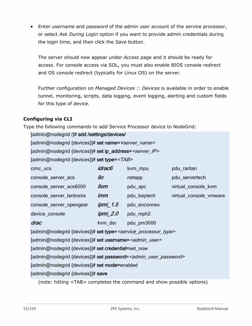
Configuring via CLI
Type the following commands to add Service Processor device to NodeGrid:
[admin@nodegrid /]# add /settings/devices/
[admin@nodegrid {devices}]# set name=<server_name>
[admin@nodegrid {devices}]# set ip_address=<server_IP>
[admin@nodegrid {devices}]# set type=<TAB>
cimc_ucs idrac6 kvm_mpu pdu_raritan
console_server_acs ilo netapp pdu_servertech
console_server_acs6000 ilom pdu_apc virtual_console_kvm
console_server_lantronix imm pdu_baytech virtual_console_vmware
console_server_opengear ipmi_1.5 pdu_enconnex
device_console ipmi_2.0 pdu_mph2
drac kvm_dsr pdu_pm3000
[admin@nodegrid {devices}]# set type=<service_processor_type>
[admin@nodegrid {devices}]# set username=<admin_user>
[admin@nodegrid {devices}]# set credential=set_now
[admin@nodegrid {devices}]# set password=<admin_user_password>
[admin@nodegrid {devices}]# set mode=enabled
[admin@nodegrid {devices}]# save
(note: hitting <TAB> completes the command and show possible options)
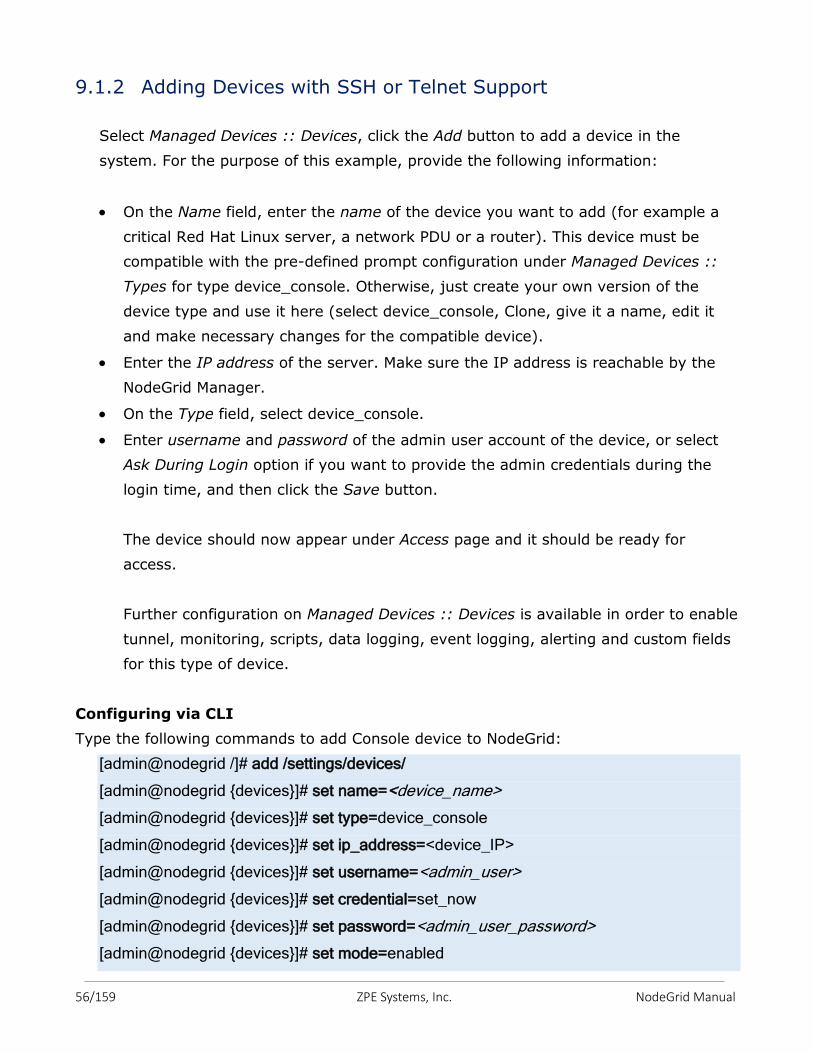
56/159 ZPE Systems, Inc. NodeGrid Manual
9.1.2 Adding Devices with SSH or Telnet Support
Select Managed Devices :: Devices, click the Add button to add a device in the
system. For the purpose of this example, provide the following information:
On the Name field, enter the name of the device you want to add (for example a
critical Red Hat Linux server, a network PDU or a router). This device must be
compatible with the pre-defined prompt configuration under Managed Devices ::
Types for type device_console. Otherwise, just create your own version of the
device type and use it here (select device_console, Clone, give it a name, edit it
and make necessary changes for the compatible device).
Enter the IP address of the server. Make sure the IP address is reachable by the
NodeGrid Manager.
On the Type field, select device_console.
Enter username and password of the admin user account of the device, or select
Ask During Login option if you want to provide the admin credentials during the
login time, and then click the Save button.
The device should now appear under Access page and it should be ready for
access.
Further configuration on Managed Devices :: Devices is available in order to enable
tunnel, monitoring, scripts, data logging, event logging, alerting and custom fields
for this type of device.
Configuring via CLI
Type the following commands to add Console device to NodeGrid:
[admin@nodegrid /]# add /settings/devices/
[admin@nodegrid {devices}]# set name=<device_name>
[admin@nodegrid {devices}]# set type=device_console
[admin@nodegrid {devices}]# set ip_address=<device_IP>
[admin@nodegrid {devices}]# set username=<admin_user>
[admin@nodegrid {devices}]# set credential=set_now
[admin@nodegrid {devices}]# set password=<admin_user_password>
[admin@nodegrid {devices}]# set mode=enabled
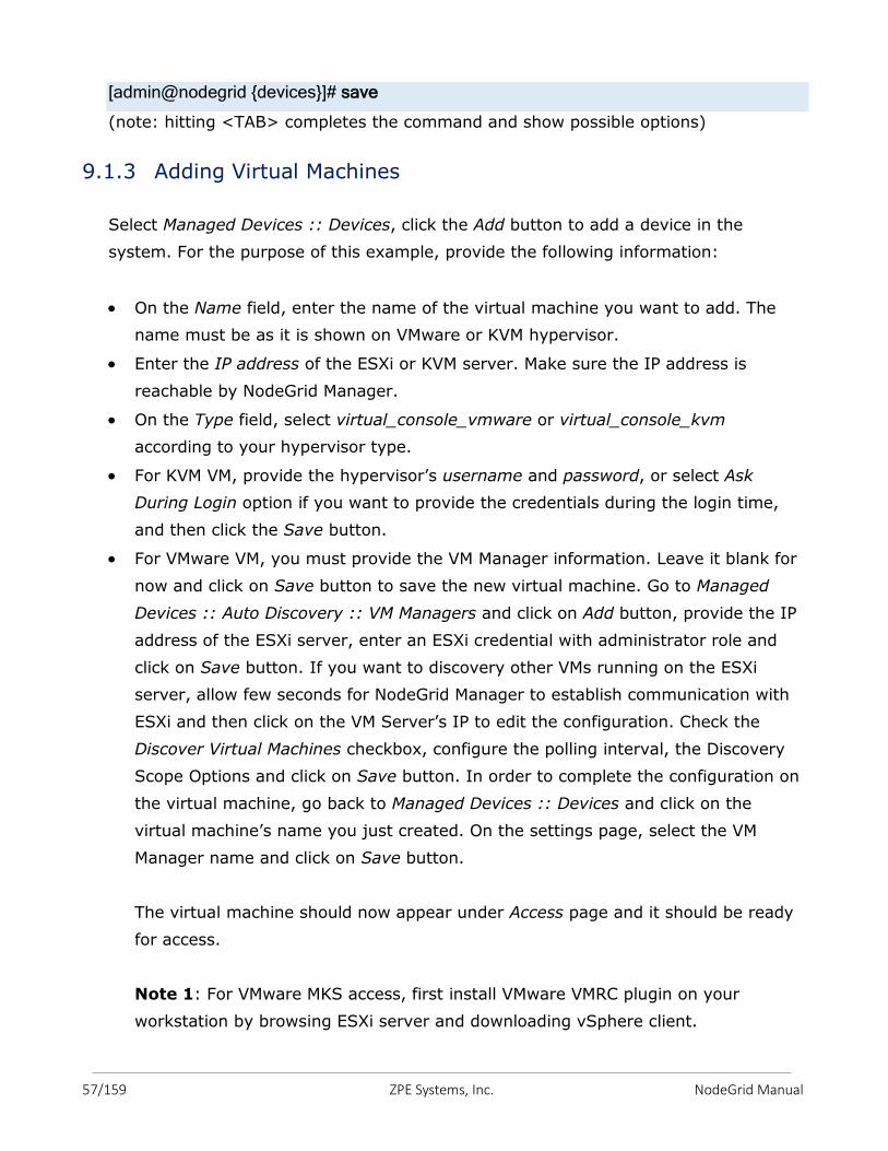
57/159 ZPE Systems, Inc. NodeGrid Manual
[admin@nodegrid {devices}]# save
(note: hitting <TAB> completes the command and show possible options)
9.1.3 Adding Virtual Machines
Select Managed Devices :: Devices, click the Add button to add a device in the
system. For the purpose of this example, provide the following information:
On the Name field, enter the name of the virtual machine you want to add. The
name must be as it is shown on VMware or KVM hypervisor.
Enter the IP address of the ESXi or KVM server. Make sure the IP address is
reachable by NodeGrid Manager.
On the Type field, select virtual_console_vmware or virtual_console_kvm
according to your hypervisor type.
For KVM VM, provide the hypervisor’s username and password, or select Ask
During Login option if you want to provide the credentials during the login time,
and then click the Save button.
For VMware VM, you must provide the VM Manager information. Leave it blank for
now and click on Save button to save the new virtual machine. Go to Managed
Devices :: Auto Discovery :: VM Managers and click on Add button, provide the IP
address of the ESXi server, enter an ESXi credential with administrator role and
click on Save button. If you want to discovery other VMs running on the ESXi
server, allow few seconds for NodeGrid Manager to establish communication with
ESXi and then click on the VM Server’s IP to edit the configuration. Check the
Discover Virtual Machines checkbox, configure the polling interval, the Discovery
Scope Options and click on Save button. In order to complete the configuration on
the virtual machine, go back to Managed Devices :: Devices and click on the
virtual machine’s name you just created. On the settings page, select the VM
Manager name and click on Save button.
The virtual machine should now appear under Access page and it should be ready
for access.
Note 1: For VMware MKS access, first install VMware VMRC plugin on your
workstation by browsing ESXi server and downloading vSphere client.
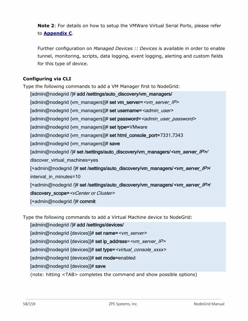
58/159 ZPE Systems, Inc. NodeGrid Manual
Note 2: For details on how to setup the VMWare Virtual Serial Ports, please refer
to Appendix C.
Further configuration on Managed Devices :: Devices is available in order to enable
tunnel, monitoring, scripts, data logging, event logging, alerting and custom fields
for this type of device.
Configuring via CLI
Type the following commands to add a VM Manager first to NodeGrid:
[admin@nodegrid /]# add /settings/auto_discovery/vm_managers/
[admin@nodegrid {vm_managers}]# set vm_server=<vm_server_IP>
[admin@nodegrid {vm_managers}]# set username=<admin_user>
[admin@nodegrid {vm_managers}]# set password=<admin_user_password>
[admin@nodegrid {vm_managers}]# set type=VMware
[admin@nodegrid {vm_managers}]# set html_console_port=7331,7343
[admin@nodegrid {vm_managers}]# save
[admin@nodegrid /]# set /settings/auto_discovery/vm_managers/<vm_server_IP>/
discover_virtual_machines=yes
[+admin@nodegrid /]# set /settings/auto_discovery/vm_managers/<vm_server_IP>/
interval_in_minutes=10
[+admin@nodegrid /]# set /settings/auto_discovery/vm_managers/<vm_server_IP>/
discovery_scope=<vCenter or Cluster>
[+admin@nodegrid /]# commit
Type the following commands to add a Virtual Machine device to NodeGrid:
[admin@nodegrid /]# add /settings/devices/
[admin@nodegrid {devices}]# set name=<vm_server>
[admin@nodegrid {devices}]# set ip_address=<vm_server_IP>
[admin@nodegrid {devices}]# set type=<virtual_console_xxxx>
[admin@nodegrid {devices}]# set mode=enabled
[admin@nodegrid {devices}]# save
(note: hitting <TAB> completes the command and show possible options)
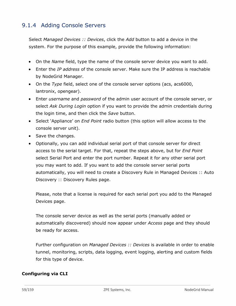
59/159 ZPE Systems, Inc. NodeGrid Manual
9.1.4 Adding Console Servers
Select Managed Devices :: Devices, click the Add button to add a device in the
system. For the purpose of this example, provide the following information:
On the Name field, type the name of the console server device you want to add.
Enter the IP address of the console server. Make sure the IP address is reachable
by NodeGrid Manager.
On the Type field, select one of the console server options (acs, acs6000,
lantronix, opengear).
Enter username and password of the admin user account of the console server, or
select Ask During Login option if you want to provide the admin credentials during
the login time, and then click the Save button.
Select ‘Appliance’ on End Point radio button (this option will allow access to the
console server unit).
Save the changes.
Optionally, you can add individual serial port of that console server for direct
access to the serial target. For that, repeat the steps above, but for End Point
select Serial Port and enter the port number. Repeat it for any other serial port
you may want to add. If you want to add the console server serial ports
automatically, you will need to create a Discovery Rule in Managed Devices :: Auto
Discovery :: Discovery Rules page.
Please, note that a license is required for each serial port you add to the Managed
Devices page.
The console server device as well as the serial ports (manually added or
automatically discovered) should now appear under Access page and they should
be ready for access.
Further configuration on Managed Devices :: Devices is available in order to enable
tunnel, monitoring, scripts, data logging, event logging, alerting and custom fields
for this type of device.
Configuring via CLI
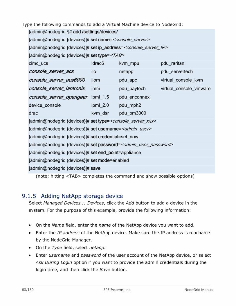
60/159 ZPE Systems, Inc. NodeGrid Manual
Type the following commands to add a Virtual Machine device to NodeGrid:
[admin@nodegrid /]# add /settings/devices/
[admin@nodegrid {devices}]# set name=<console_server>
[admin@nodegrid {devices}]# set ip_address=<console_server_IP>
[admin@nodegrid {devices}]# set type=<TAB>
cimc_ucs idrac6 kvm_mpu pdu_raritan
console_server_acs ilo netapp pdu_servertech
console_server_acs6000 ilom pdu_apc virtual_console_kvm
console_server_lantronix imm pdu_baytech virtual_console_vmware
console_server_opengear ipmi_1.5 pdu_enconnex
device_console ipmi_2.0 pdu_mph2
drac kvm_dsr pdu_pm3000
[admin@nodegrid {devices}]# set type=<console_server_xxx>
[admin@nodegrid {devices}]# set username=<admin_user>
[admin@nodegrid {devices}]# set credential=set_now
[admin@nodegrid {devices}]# set password=<admin_user_password>
[admin@nodegrid {devices}]# set end_point=appliance
[admin@nodegrid {devices}]# set mode=enabled
[admin@nodegrid {devices}]# save
(note: hitting <TAB> completes the command and show possible options)
9.1.5 Adding NetApp storage device Select Managed Devices :: Devices, click the Add button to add a device in the
system. For the purpose of this example, provide the following information:
On the Name field, enter the name of the NetApp device you want to add.
Enter the IP address of the NetApp device. Make sure the IP address is reachable
by the NodeGrid Manager.
On the Type field, select netapp.
Enter username and password of the user account of the NetApp device, or select
Ask During Login option if you want to provide the admin credentials during the
login time, and then click the Save button.
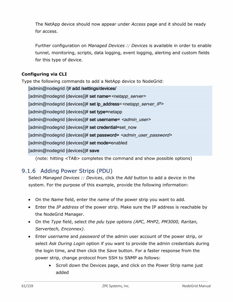
61/159 ZPE Systems, Inc. NodeGrid Manual
The NetApp device should now appear under Access page and it should be ready
for access.
Further configuration on Managed Devices :: Devices is available in order to enable
tunnel, monitoring, scripts, data logging, event logging, alerting and custom fields
for this type of device.
Configuring via CLI
Type the following commands to add a NetApp device to NodeGrid:
[admin@nodegrid /]# add /settings/devices/
[admin@nodegrid {devices}]# set name=<netapp_server>
[admin@nodegrid {devices}]# set ip_address=<netapp_server_IP>
[admin@nodegrid {devices}]# set type=netapp
[admin@nodegrid {devices}]# set username= <admin_user>
[admin@nodegrid {devices}]# set credential=set_now
[admin@nodegrid {devices}]# set password= <admin_user_password>
[admin@nodegrid {devices}]# set mode=enabled
[admin@nodegrid {devices}]# save
(note: hitting <TAB> completes the command and show possible options)
9.1.6 Adding Power Strips (PDU) Select Managed Devices :: Devices, click the Add button to add a device in the
system. For the purpose of this example, provide the following information:
On the Name field, enter the name of the power strip you want to add.
Enter the IP address of the power strip. Make sure the IP address is reachable by
the NodeGrid Manager.
On the Type field, select the pdu type options (APC, MHP2, PM3000, Raritan,
Servertech, Enconnex).
Enter username and password of the admin user account of the power strip, or
select Ask During Login option if you want to provide the admin credentials during
the login time, and then click the Save button. For a faster response from the
power strip, change protocol from SSH to SNMP as follows:
Scroll down the Devices page, and click on the Power Strip name just
added
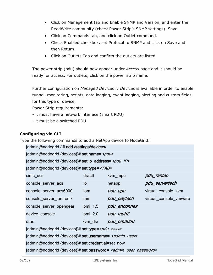
62/159 ZPE Systems, Inc. NodeGrid Manual
Click on Management tab and Enable SNMP and Version, and enter the
ReadWrite community (check Power Strip’s SNMP settings). Save.
Click on Commands tab, and click on Outlet command.
Check Enabled checkbox, set Protocol to SNMP and click on Save and
then Return.
Click on Outlets Tab and confirm the outlets are listed
The power strip (pdu) should now appear under Access page and it should be
ready for access. For outlets, click on the power strip name.
Further configuration on Managed Devices :: Devices is available in order to enable
tunnel, monitoring, scripts, data logging, event logging, alerting and custom fields
for this type of device.
Power Strip requirements:
- it must have a network interface (smart PDU)
- it must be a switched PDU
Configuring via CLI
Type the following commands to add a NetApp device to NodeGrid:
[admin@nodegrid /]# add /settings/devices/
[admin@nodegrid {devices}]# set name=<pdu>
[admin@nodegrid {devices}]# set ip_address=<pdu_IP>
[admin@nodegrid {devices}]# set type=<TAB>
cimc_ucs idrac6 kvm_mpu pdu_raritan
console_server_acs ilo netapp pdu_servertech
console_server_acs6000 ilom pdu_apc virtual_console_kvm
console_server_lantronix imm pdu_baytech virtual_console_vmware
console_server_opengear ipmi_1.5 pdu_enconnex
device_console ipmi_2.0 pdu_mph2
drac kvm_dsr pdu_pm3000
[admin@nodegrid {devices}]# set type=<pdu_xxxx>
[admin@nodegrid {devices}]# set username= <admin_user>
[admin@nodegrid {devices}]# set credential=set_now
[admin@nodegrid {devices}]# set password= <admin_user_password>
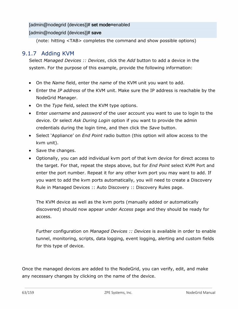
63/159 ZPE Systems, Inc. NodeGrid Manual
[admin@nodegrid {devices}]# set mode=enabled
[admin@nodegrid {devices}]# save
(note: hitting <TAB> completes the command and show possible options)
9.1.7 Adding KVM Select Managed Devices :: Devices, click the Add button to add a device in the
system. For the purpose of this example, provide the following information:
On the Name field, enter the name of the KVM unit you want to add.
Enter the IP address of the KVM unit. Make sure the IP address is reachable by the
NodeGrid Manager.
On the Type field, select the KVM type options.
Enter username and password of the user account you want to use to login to the
device. Or select Ask During Login option if you want to provide the admin
credentials during the login time, and then click the Save button.
Select ‘Appliance’ on End Point radio button (this option will allow access to the
kvm unit).
Save the changes.
Optionally, you can add individual kvm port of that kvm device for direct access to
the target. For that, repeat the steps above, but for End Point select KVM Port and
enter the port number. Repeat it for any other kvm port you may want to add. If
you want to add the kvm ports automatically, you will need to create a Discovery
Rule in Managed Devices :: Auto Discovery :: Discovery Rules page.
The KVM device as well as the kvm ports (manually added or automatically
discovered) should now appear under Access page and they should be ready for
access.
Further configuration on Managed Devices :: Devices is available in order to enable
tunnel, monitoring, scripts, data logging, event logging, alerting and custom fields
for this type of device.
Once the managed devices are added to the NodeGrid, you can verify, edit, and make
any necessary changes by clicking on the name of the device.
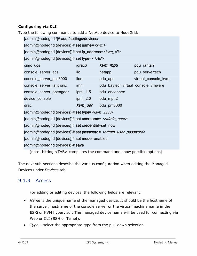
64/159 ZPE Systems, Inc. NodeGrid Manual
Configuring via CLI
Type the following commands to add a NetApp device to NodeGrid:
[admin@nodegrid /]# add /settings/devices/
[admin@nodegrid {devices}]# set name=<kvm>
[admin@nodegrid {devices}]# set ip_address=<kvm_IP>
[admin@nodegrid {devices}]# set type=<TAB>
cimc_ucs idrac6 kvm_mpu pdu_raritan
console_server_acs ilo netapp pdu_servertech
console_server_acs6000 ilom pdu_apc virtual_console_kvm
console_server_lantronix imm pdu_baytech virtual_console_vmware
console_server_opengear ipmi_1.5 pdu_enconnex
device_console ipmi_2.0 pdu_mph2
drac kvm_dsr pdu_pm3000
[admin@nodegrid {devices}]# set type=<kvm_xxxx>
[admin@nodegrid {devices}]# set username= <admin_user>
[admin@nodegrid {devices}]# set credential=set_now
[admin@nodegrid {devices}]# set password= <admin_user_password>
[admin@nodegrid {devices}]# set mode=enabled
[admin@nodegrid {devices}]# save
(note: hitting <TAB> completes the command and show possible options)
The next sub-sections describe the various configuration when editing the Managed
Devices under Devices tab.
9.1.8 Access
For adding or editing devices, the following fields are relevant:
Name is the unique name of the managed device. It should be the hostname of
the server, hostname of the console server or the virtual machine name in the
ESXi or KVM hypervisor. The managed device name will be used for connecting via
Web or CLI (SSH or Telnet).
Type – select the appropriate type from the pull-down selection.
65/159 ZPE Systems, Inc. NodeGrid Manual
The following types ilo (HP), imm (IBM), drac and idrac6 (DELL), ipmi_1.5 and
ipmi_2.0 (Super Micro), ilom (Oracle), cimc_ucs (Cisco) are for service
processors; If type is cimc_ucs then Chassis ID and Blade ID parameters become
available.
The device_console type is for generic devices that respond to SSH or Telnet
protocols;
The netapp type is for the NetApp storage devices;
The vm_console_vmware type is for VMwareTM virtual machines using MKS-Mouse
Keyboard and Screen or vSPC for virtual serial port;
The vm_console_kvm type is for KVM virtual machines using virtual serial port;
The console_server_xxx types are for Serial Consoles from the respective
manufacturers;
The pdu_xxx types are for Power Strips from the respective manufacturers;
The kvm_dsr type is for the Avocent DSR KVM.
IP Address is the managed device’s IP address. For virtual machines, enter the IP
address of the hypervisor.
Port becomes available when console_server_xxx is set in Type.
Username and Password for the privileged user on the managed device. This
account will be used for logging into the device in order to collect data logging and
event logging (Credential as Set Now). Typically, this is the admin user of the
devices. If you want to type in the credentials for each connection, set Credential
to Ask During Login. Note: vm_console_vmware type does not require username
and password.
Check Enable Hostname Detection checkbox if you want the device’s hostname to
be detected and replace the defaults name. Note: this feature does not apply to
KVM devices.
Multisession allows multiple users to log to the same managed device
simultaneously. For auditing and tracking purposes, only one user will have control
of the session at a time. The others will be in read-only mode.
Read-Write Multisession allows multiple users to have control of the session
concurrently.
Enable Send Break allows admins to customize the Break Sequence to be used by
this managed device.
Skip authentication to access device (no authentication) allows users to access the
managed devices without credentials.
66/159 ZPE Systems, Inc. NodeGrid Manual
Escape Sequence is the hot key used for the device control such as suspend a
session (^Ec.) or get help (^Ec?). By default, it is ^Ec
Power Control Key is the hot key to call the Power Control for the device. It
requires an association of the device with an outlet or outlets of a PDU in the
Managed Devices :: Device :: Commands :: Outlet page. By default, it is ^O
Show Text Information
Enable IP Alias allows to set an IP address for the device. This would be the IP
address that the user can reach and associate it to the managed device which may
be in a different network. This is also useful to set an IP address to the serial port
of the NodeGrid Serial Console.
Enter the IP Address and set the Interface. If required, enable Allow Telnet and
Allow Binary Socket and enter the respective TCP socket ports.
Address Location is a free format field for the address location of the device. You
can get the address Coordinates by clicking on the compass icon.
WEB URL is the managed device URL, if it is available. %IP is a macro that will be
replaced by the actual managed device’s IP address. You may check the Launch
URL via HTML5 checkbox.
Select an Icon for the managed device so that it helps visualize the type of device
you have.
Mode settings allow to control the state of the device.
Enabled – the device is visible on Access page. The Console connection between
NodeGrid and the device will remain established to allow collecting data logs sent
by the device’s console, regardless if the session is in use.
On-demand – the device is visible on Access page. The Console connection
between NodeGrid and the device will be established dynamically when there is a
user using the session. The connection will be disconnected when the last user
terminates the session with the device.
Disabled – the device is not visible on Access page. The Console connection
between NodeGrid and the device is not established. Use this mode if you want to
disallow temporarily access to device (for example when device is maintenance
mode).
Discovered – the device is not visible on Access page. The Console connection
between NodeGrid and the device is not established. This device was auto-
discovered and it is currently parked on this state for review by admin.
67/159 ZPE Systems, Inc. NodeGrid Manual
Expiration sets the expiration period of the managed devices (not applicable to
NodeGrid Serial console serial ports).
By default, it is Never, meaning that the device and its data will stay in the
system until admin user removes it.
Date – the device will be available until the date specified. After that date, it will
set to Disabled mode and admin user has 10 days to take an action. After the 10
days, the device and its data will be removed from the system.
Days – this is similar to timeout – if there is no update on the device’s
configuration, after the specified days, the device and its data will be removed
from the system. This is independent of the use of the device.
Both Date and Days will be mostly applied to VM devices in order to get in sync
with the ESXi Servers where the VMs are constantly being added, moved, and
deleted, and the NodeGrid managed device license may become available.
End Point setting applies for console_server_xxx and kvm_xxx types. This allows
NodeGrid to identify if the managed device is for the appliance itself or for one of
the serial ports on the console server or the kvm ports of the kvm.
Tunnel allows a remote workstation to establish a tunnel connection to the
managed device. Specify the Tunneled Ports for that connection. Some default
ports are already set depending on the device type.
Allow SSH protocol enables the authorized user to ssh to the NodeGrid IP address
with the SSH Port. Example: ssh –l usera:5522 NodeGrid_IP
Allow Telnet protocol enables the authorized user to telnet to the NodeGrid IP
address with the Telnet Port. Example: telnet NodeGrid_IP 9901
Allow Binary socket enables the authorized user to establish a raw socket
connection with the TCP Socket Port.
9.1.9 Management
Editing the device, the admin user can modify parameters under Management tab
for Protocol (telnet/ssh, IPMI, SNMP), Monitoring (IPMI, SNMP, Nominal), and
Scripts. The parameters will depend on the device type to show what is supported.
In case of console_server_xxx and kvm_xxx types, the Discovery Ports option is
available.
68/159 ZPE Systems, Inc. NodeGrid Manual
9.1.10 Logging Data Log and Event Log selection will configure the system to collect data log (not
available for MKS sessions) and event log from the device (for service processor
device type only). Event Log Frequency and Event Log Unit will set the frequency
to collect the event log from the service processor. Both alerts and events support
Alert Strings and Event Strings, which are regular expression pattern string that
are evaluated against the data source stream as the data is collected. Events are
generated for each match.
9.1.11 Custom Fields Occasionally, it is necessary to add pieces of information to devices that are not
available by default. NodeGrid system allows creation of custom fields so that they
are part of information of the device. Any custom field added to the device is
readily available for search.
Go to Managed Devices page and click on the Device name you want to add the
custom fields.
Go to the Custom Fields page, click on Add button and enter the Field Name and
its Field Value. Save the changes.
Repeat the steps to add as many fields as necessary.
The custom fields and values will be part of the Devices’ information. To confirm
the new fields, go to Access page, and click on the Device name. Scroll down the
Information page and check the last lines.
9.1.12 Commands Each device brings some Action buttons such as Console, Web, KVM, on the Access
page, and some other buttons such as Data Log, Power, or Outlet on the device’s
Information page. These buttons are listed in the Commands page of the device.
The admin user can go to Managed Devices page and click on the device, and then
go to Commands tab.
Although the admin user can disable the commands, it is recommended to leave
them as enabled so that users can utilize all features available on the NodeGrid. If
admin user wishes to not have them available to certain users or groups, this can
be accomplished via Authorization.
69/159 ZPE Systems, Inc. NodeGrid Manual
Also, the admin user can add supported features which will depend on the device
type.
For example, the admin user can add Outlet command to a NodeGrid Serial
Console serial port, and associate outlets of a PDU to have power integration
within the serial session.
For NodeGrid Serial Console
Power Control integration with Network Switched Power Strips to power on, power
off, power cycle attached serial devices such as server, router, network switch and
storage devices. Follow steps below to configure the Power Control for the serial
port.
1) Add a Switched Power Strip from the network
a. Go to Managed Devices and click on Add button.
b. Enter a name, select the PDU type, IP Address and username/password
of the Power Strip.
c. Click on Save
2) Scroll down the Devices page, and click on the Power Strip name just added
a. Click on Management tab
b. Enable SNMP and Version, and enter the ReadWrite community (check
Power Strip’s SNMP settings)
c. Click on Save
d. Click on Commands tab, and click on Outlet command
e. Check Enabled checkbox, set Protocol to SNMP and save.
f. Click on Outlets Tab and confirm the outlets are listed
3) Click on Devices, and click on the serial port name you want to integrate power
outlet(s)
a. Click on Commands tab and click on Outlet command
b. Check Enabled checkbox
c. Select the outlet(s) and click on Add button
d. Click on Save
e. Repeat these steps for other serial ports and outlets.
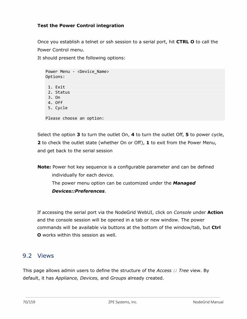
70/159 ZPE Systems, Inc. NodeGrid Manual
Test the Power Control integration
Once you establish a telnet or ssh session to a serial port, hit CTRL O to call the
Power Control menu.
It should present the following options:
Power Menu - <Device_Name> Options: 1. Exit 2. Status 3. On 4. Off 5. Cycle Please choose an option:
Select the option 3 to turn the outlet On, 4 to turn the outlet Off, 5 to power cycle,
2 to check the outlet state (whether On or Off), 1 to exit from the Power Menu,
and get back to the serial session
Note: Power hot key sequence is a configurable parameter and can be defined
individually for each device.
The power menu option can be customized under the Managed
Devices::Preferences.
If accessing the serial port via the NodeGrid WebUI, click on Console under Action
and the console session will be opened in a tab or new window. The power
commands will be available via buttons at the bottom of the window/tab, but Ctrl
O works within this session as well.
9.2 Views
This page allows admin users to define the structure of the Access :: Tree view. By
default, it has Appliance, Devices, and Groups already created.
71/159 ZPE Systems, Inc. NodeGrid Manual
Admin user may create other groups and sub-groups and add devices that belong to that
group, or add under the existing groups.
9.3 Types
Target Types hold specific information about the family type (required for the device
driver identification), protocol to be used for communication, and the template associated
to different targets. NodeGrid provides several pre-configured target types that can be
cloned and modify in order to grow even more your portfolio. Select a single target type
and use the Clone button to make a copy of it. You can edit the target type in order to
make further changes. Pre-defined target types can be modified, but cannot be deleted.
9.4 Auto Discovery
This feature allows newly discovered devices to be cloned from existing devices matching
their profile and build dynamic access groups. For best results with this feature, make
sure the device to be used as reference in the cloning process is correctly configured.
Verify that username, password and IP address are correct by accessing the device.
Verify that the data logging and event logging settings are correct by auditing the log
files. Verify that events are being detected based on data logging and event logging by
simulating events and checking if any notification was created. Verify that the device is in
the desirable authorization group with correct access rights.
The Auto Discovery configuration happens in 3 processes:
a. Manually add a device to NodeGrid (process done in sections 9.1.1 through 9.1.7) –
at least one device of each type will need to be added manually first in order for the
NodeGrid to discover the devices of the same type.
b. Setup the discovery of the devices via Network Scan, VM Manager, and HostName
Detection
c. Create Discovery Rules to define the action you want to take with the discovered
devices.
9.4.1 Network Scan
72/159 ZPE Systems, Inc. NodeGrid Manual
This page allows you to create a Network Scan ID for the process on how to
discover the devices on your network.
Click on Add button.
Enter a Scan ID and the IP range (start and end).
You can select/unselect the 3 options depending on how you want to discover your
network devices:
- Similar Devices (select one of the devices from the drop-down menu),
- Port Scan and enter a list of ports in the Port List field,
- Ping
You may want to change the scan interval or leave it the default 60 minutes.
Save.
You may create other Network Scans for other device types.
9.4.2 VM Manager
This feature allows NodeGrid to communicate to VMware vCenterTM in order to
generate session tickets for MKS sessions and also to execute power commands
for managed devices of VM_Console type.
VM Server – provide the IP address of the vCenterTM server.
Username and Password for the user with admin privileges in vCenterTM
Click Save.
In order to discover virtual machines from vCenterTM, Discover Virtual Machines
needs to be enabled. Provide the polling interval (in minutes) for how often the list
of VMs will be retrieved from vCenterTM. On the Discovery Scope Options select the
data centers and/or clusters from where NodeGrid will search for virtual machine
names. Setting the correct scope will help to improve performance especially in
large data centers. The list of names will be used by the auto-discovery process
following your discovery rules.
9.4.3 Discovery Rules
73/159 ZPE Systems, Inc. NodeGrid Manual
Click Add, and follow the options below for the device type you want to discover
and add to the NodeGrid Managed Devices.
Service Processor (type: IPMI, ILO, ILOM, DRAC, iDRAC)
- Enter a name for the rule
- On Discovery Method select DHCP. This enables NodeGrid Manager to
evaluate the discovery rules for any server with a service processor that
requests DHCP. Please note that this option requires DHCP Server enable
under Network :: DHCP Server.
- For Mac Address field provide the three first octets or full MAC Address of
the devices that you want to discover. In the Host or VM Identifier field,
provide a substring to identify the server names for this configuration.
Fields left blank will not be used during the discovery to match this
configuration.
- In the Action field, select action Clone (Mode: Enabled).
- For the Clone From field, select the server name from section 5.3.1 and
then, click Save.
NOTE: if the Service Processors’ management port is set with static IP
address, the on Discovery Method select Network Scan. In the Scan ID
field select the Scan ID for the Similar Devices created in section 5.3.8.b.
Network Devices (type: device_console)
- Enter a name for the rule
- On Discovery Method select Network Scan. In the Scan ID field select
the Scan ID for the Similar Devices created in section 5.3.8.b.
- In the Action field, select action Clone (Mode: Enabled).
- For the Clone From field, select the console server name from section
5.3.2 and then, click Save.
VMWare Virtual Machines (type: virtual_console_vmware) running on
ESXi or vCenter
- Enter a name for the rule
- On Discovery Method, select VM Manager. In the Datacenter, Cluster
and Host VM Identifier fields, provide a substring to identify the
datacenter, cluster or virtual machine names for this configuration.
74/159 ZPE Systems, Inc. NodeGrid Manual
Otherwise, leave these fields blank and this will allow any virtual machine
to match this configuration.
- For the Action field, select action Clone (Mode: Enabled).
- For the Clone From field, select the virtual machine name from section
5.3.3 and then, click Save.
Note: For details on how to setup the VMWare Virtual Serial Ports, please
refer to Appendix B.
VMWare Virtual Port - virtual serial port (vSPC on ESXi - type:
virtual_console_vmware)
- Enter a name for the rule
- On Discovery Method select VM Serial.
- In the Host or VM Identifier field, provide a substring to identify the
virtual machine names for this configuration. You can also provide the
Port URI information configured under the VM serial port in the ESXi
server. This field can be used to provide group names or an identifier for
a group of servers. Otherwise, leave both fields blank and this will allow
any virtual machine to match this configuration.
- For the Action field, select action Clone (Mode: Enabled).
- For the Clone From field, select the virtual machine name from section
5.3.3 and then, click Save.
Console Servers (type: console_server_xxxxx)
- Enter a name for the rule
- On Discovery Method select Network Scan. In the Scan ID field select
the Scan ID for the Similar Devices created in section 5.3.8.b for Console
Server.
- In the Action field, select action Clone (Mode: Enabled).
- For the Clone From field, select the console server name from section
5.3.4 and then, click Save.
Console Servers Serial Ports (type: console_server_xxxxx)
- Enter a name for the rule
75/159 ZPE Systems, Inc. NodeGrid Manual
- On Discovery Method select Console Server Ports. In the Port List field,
provide a list of individual ports separated by commas and/or port range
separated by dash to be discovered. In the Host or VM Identifier field,
provide a substring to identify the console server names or console
server port names for this configuration. Otherwise, leave these fields
blank and this will allow any console server or port to match this
configuration.
- For the Action field, select action Clone (Mode: Enabled).
- For the Clone From field, select the console server name from section
5.3.4 and then, click Save.
Storage Devices (type: netapp)
- Enter a name for the rule
- On Discovery Method select Network Scan. In the Scan ID field select
the Scan ID for the Similar Devices created in section 5.3.8.b for NetApp.
- In the Action field, select action Clone (Mode: Enabled).
- For the Clone From field, select the netapp name from section 5.3.5 and
then, click Save.
Power Strips (type: pdu_xxxx)
- Enter a name for the rule
- On Discovery Method select Network Scan. In the Scan ID field select
the Scan ID for the Similar Devices created in section 5.3.8.b for PDU.
- In the Action field, select action Clone (Mode: Enabled).
- For the Clone From field, select the pdu name from section 5.3.6 and
then, click Save.
KVM (type: kvm_xxxx)
- Enter a name for the rule
- On Discovery Method select Network Scan. In the Scan ID field select
the Scan ID for the Similar Devices created in section 5.3.8.b for KVM.
- In the Action field, select action Clone (Mode: Enabled).
- For the Clone From field, select the kvm name from section 5.3.7 and
then, click Save.
KVM Ports (type: console_server_xxxxx)
76/159 ZPE Systems, Inc. NodeGrid Manual
- Enter a name for the rule
- On Discovery Method select KVM Ports. In the Port List field, provide a
list of individual ports separated by commas and/or port range separated
by dash to be discovered. In the Host or VM Identifier field, provide a
substring to identify the kvm names or kvm port names for this
configuration. Otherwise, leave these fields blank and this will allow any
kvm or port to match this configuration.
- For the Action field, select action Clone (Mode: Enabled).
- For the Clone From field, select the kvm name from section 5.3.7 and
then, click Save.
The Auto-Discovery :: Discovery Rules Up and Down buttons allow you to change
the order of the discovery rule within a given Discovery Method. This is important
if the administrator wants to set discovery rules with different priorities or even
rules to drop the discovery match (by selecting action Discard).
9.4.4 Hostname Detection
This page allows admin users to add probes and matches’ strings for detecting
hostnames of the devices (network or serial).
By default, it has already some probes and matches for most of following devices
types: PDUs, NetApp, Console Servers, Device Consoles, and Service Processors.
These device types have the parameter “Enable Hostname Detection” checkbox.
NodeGrid will send the first probe, and wait for a match. If there is no match, it
will send the second probe, and so on. Once there is a match, the probing stops
for that device.
9.4.5 Discovery Logs
The Discovery Logs page will list all the discovered devices with timestamp, and
their IP addresses, Device Names, Discovery Method, and Action taken. The list
will continue to grow due to the network devices scan interval, vm discovery
polling interval, DHCP requests, and Discovery Ports interval.
The logs can be reset by clicking on the Reset Logs button.
77/159 ZPE Systems, Inc. NodeGrid Manual
9.4.6 Discover Now
Admin users may force a discovery if one wants to discover devices and doesn’t
want to wait for the discovery interval.
Select the Name(s) of the discovery you want to start the discovery, and then click
on the Discovery Now button.
You may want to look the logs in Discovery Logs page for updates on the discovery
status, or check Access or Managed Devices pages to confirm the devices were
properly discovered.
78/159 ZPE Systems, Inc. NodeGrid Manual
Cloud is a NodeGrid feature that establishes a secure and resilient connection among
other NodeGrid platforms so that when Cloud Clustering is enabled, multiple NodeGrid
systems can easily manage and access all managed devices from other nodes.
NodeGrid makes cloud access management even easier with cloud asset search. By
logging into any NodeGrid node users can search the entire NodeGrid-managed
enterprise network and cloud with a single interface.
This allows vertical and horizontal scalability.
10.1 Peers
This page will list all NodeGrid platforms that are enrolled to the cloud.
The table shows the name of each NodeGrid, their IP Addresses, type, and status of
communication with other peers.
You may remove peers by selecting them and then clicking on Remove button.
If the NodeGrid is the coordinator, it cannot be removed from the table.
10.2 Settings
On this page you can enable the Cloud by checking the Enable Cloud checkbox.
Then set it to be either the Coordinator or a Peer.
If the NodeGrid is the coordinator, make sure the Allow Enrollment checkbox is checked,
and enter the Cloud Name and Pre-Shared Key so that peers can be enrolled to the
Cloud.
Please note that the Cloud Name and the Pre-Shared Key will be used in the Peer’s
settings.
If the NodeGrid is the Peer, then enter the Coordinator’s Cloud Name, IP Address, and
the Pre-Shared Key.
10. CLOUD
79/159 ZPE Systems, Inc. NodeGrid Manual
Set other NodeGrid systems as Peers.
Alternatively, admin user has the option to enroll the peers automatically as this feature
is enabled by default (Enable Automatic Enrollment).
Once the Coordinator is enabled and configured, the admin user can add a range of IPs
where other NodeGrid systems are on the network.
Go to Cloud :: Settings :: Automatic Enrollment Range and enter the start and end IP
addresses that are reachable by the Coordinator.
This way, the Coordinator will communicate with any NodeGrid system on those ranges
and add them to the Cloud, thus eliminating the need to go to each of the NodeGrid
nodes and set them as peers.
Note that Coordinator is only required for the enrollment of the peers. Once all NodeGrid
systems were enrolled into the Cloud, the Coordinator can be set as Peers.
Also, one Peer can be promoted to be a Coordinator by simply selecting the Coordinator
type. The changes automatically reflect on all systems on the cloud.
Check the Enable Clustering checkbox for allowing other NodeGrid systems to manage,
access, and search all managed devices from other nodes.
Check the Enable Peer Management checkbox if you want to allow the NodeGrid to have
its software upgraded via the Cloud from other peers.
10.3 Management
The Cloud :: Management page lists all NodeGrid systems on the Cloud.
Select the desired nodes that have the Management Status as Idle. If the status shows
disabled, it means that the NodeGrid has Peer Management feature disabled.
Once the selection is done, click on the Software Upgrade button.
Select Remote Server and enter URL, Username, and Password.
Note that URL should include the remote server’s IP or hostname, file path, and the ISO
file.
For example:
URL: ftp://192.168.2.200/nodegrid/NodeGrid_Platform_v3.1.0_20160127.iso
80/159 ZPE Systems, Inc. NodeGrid Manual
Then click on SW upgrade button.
Please, be careful to not select the option Format partitions before upgrade unless it is
intentional. In this case, all selected NodeGrid systems will have their partitions
formatted.
If downloading the software, you have the option to Restore configuration saved on
version upgrade or Apply factory default configuration.
81/159 ZPE Systems, Inc. NodeGrid Manual
The security menu options are as follows:
11.1 Local Accounts
The NodeGrid system installs with a built-in admin user account with full access
over the environment in order to configure network, security, authentication,
authorization, add devices and other users. The user admin account cannot be deleted
and it has the default password admin. It is strongly recommended that admins change
the default password during the first login by using the Change Password option on the
pull-down menu under your username in the top right corner. New users can be added
by the administrator. The admin can force passwords to be changed upon next login and
set expiration dates for the user accounts. Regardless of activation options, users can
change their own passwords at any time. All users have access to all enabled managed
devices by default. Based on the groups they are assigned to, these users have limited
access to NodeGrid Web portal management attributes. The users’ privileges can be
modified (elevated or reduced) by setting profile and access rights in an authorization
group. A user who belongs to group Admin will have the same administration privileges
as the admin user. Each user must have a specific user account on NodeGrid or on the
enterprise authentication server. A user can be assigned to one or more authorization
groups.
Adding new users:
1. Click on Local Accounts
2. A list of all users will be displayed on the User Names screen;
3. Click on Add and the Local User Information screen will be displayed;
4. Type a new user name and password and then confirm it;
5. Optionally, check the Hash Format Password checkbox; (see Note below about
Hash Format Password)
6. Enter Account Expiration Date (optional);
11. SECURITY
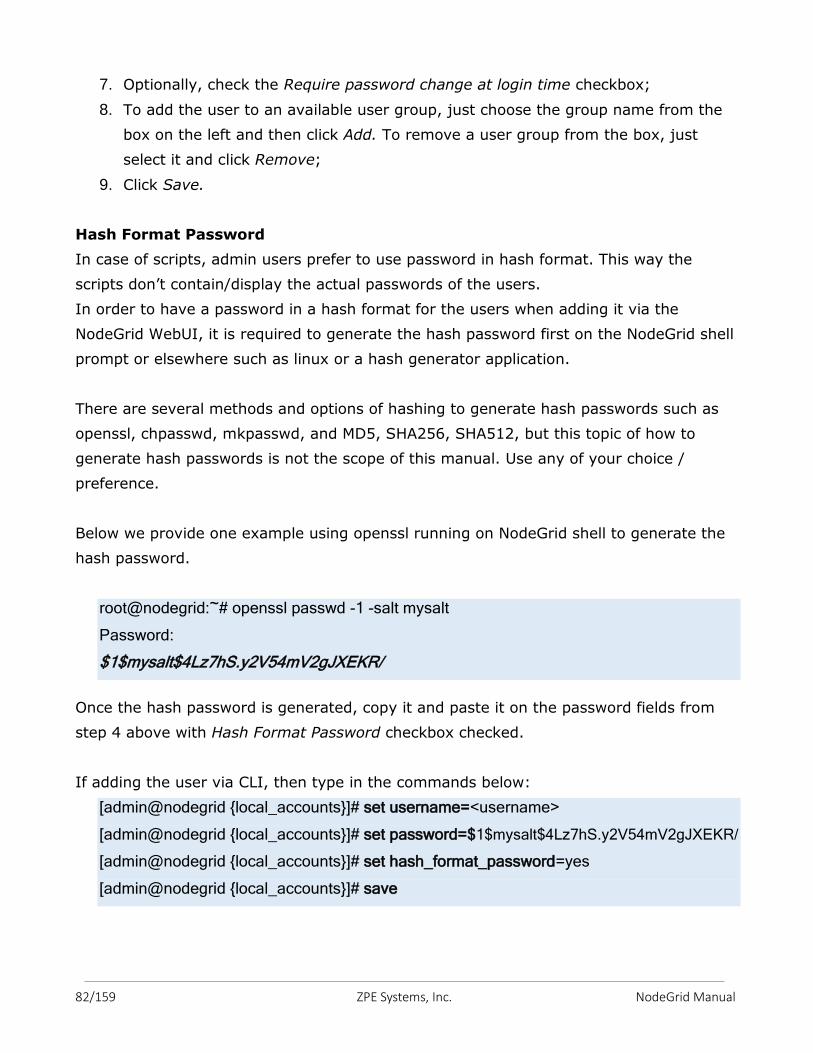
82/159 ZPE Systems, Inc. NodeGrid Manual
7. Optionally, check the Require password change at login time checkbox;
8. To add the user to an available user group, just choose the group name from the
box on the left and then click Add. To remove a user group from the box, just
select it and click Remove;
9. Click Save.
Hash Format Password
In case of scripts, admin users prefer to use password in hash format. This way the
scripts don’t contain/display the actual passwords of the users.
In order to have a password in a hash format for the users when adding it via the
NodeGrid WebUI, it is required to generate the hash password first on the NodeGrid shell
prompt or elsewhere such as linux or a hash generator application.
There are several methods and options of hashing to generate hash passwords such as
openssl, chpasswd, mkpasswd, and MD5, SHA256, SHA512, but this topic of how to
generate hash passwords is not the scope of this manual. Use any of your choice /
preference.
Below we provide one example using openssl running on NodeGrid shell to generate the
hash password.
root@nodegrid:~# openssl passwd -1 -salt mysalt
Password:
$1$mysalt$4Lz7hS.y2V54mV2gJXEKR/
Once the hash password is generated, copy it and paste it on the password fields from
step 4 above with Hash Format Password checkbox checked.
If adding the user via CLI, then type in the commands below:
[admin@nodegrid {local_accounts}]# set username=<username>
[admin@nodegrid {local_accounts}]# set password=$1$mysalt$4Lz7hS.y2V54mV2gJXEKR/
[admin@nodegrid {local_accounts}]# set hash_format_password=yes
[admin@nodegrid {local_accounts}]# save
83/159 ZPE Systems, Inc. NodeGrid Manual
11.2 Authorization
There are two default authorization groups: admin and users. An administrator can add
new groups and change authorization/permission settings of the groups. Groups can
restrict or expand user access rights to managed devices and to the system.
Admin group members have the same access and configuration authorizations that the
default admin user has and full administrative control that cannot be changed. For
example: users of the admin group can manager other users, add/delete managed
devices, add new groups, set up authorization and authentication, enable services and
perform all types of configuration and maintenance on the system. It is the highest
privilege level.
User group members have regular access to managed devices and limited access to the
system. This is the default group for new users added in the system. Authorization
permissions of the group can be changed by an admin user.
Adding new groups:
1. Click on Authorization and the Groups screen will be shown with a list of the
default authorization groups available and additional authorization groups created;
2. Click Add;
3. Type the name of the new group you want to create and then click on Save;
Configuring Members of the authorization group:
1. Click the Members button
2. Click on Add and select the members to add to this group by moving them to the
box on the right. You can also make a comma-separated list of remote users that
should belong to this group. Click on Save to accept your changes.
3. If you want to remove members, select the member you want to remove from the
list and click Delete. This will delete the selected members;
Configuring Profiles of the authorization group:
1. Click on the Profile button
84/159 ZPE Systems, Inc. NodeGrid Manual
2. Select the System Permissions which should be enabled for this group; Selecting
all permissions will allow this user full management access to the system.
3. Select the Profile Settings which should be enabled for this group. The menu-
driven option will show an indexed list of all managed devices every time a CLI
session is opened. The user just needs to select the index number to go directly to
the desired managed device. Custom timeout allows the members of this group to
have their own timeout session.
4. Click on Save.
Configuring Devices of the authorization group:
1. Click on the Devices button
2. Click on Add;
3. To move managed devices from the available device list on the left to the list of
authorized devices on the right, double click on the name or select the device and
then click Add. Devices can be removed from the box on the right by double
clicking on the device or by clicking on the delete button after selecting to device
to be removed;
4. Select desired device permissions and click Save.
5. To edit access rights, select the checkbox next to the name(s) available and then,
click on Edit. The Device Permissions will be displayed on the screen. Choose the
desired access rights and click the Save button.
6. If you want to remove devices, select the device's box you want to remove from
the list and click on Delete. This will delete the selected devices.
Configuring Outlets of the authorization group:
1. Click on the Outlets button
2. Click on Add;
3. To move outlets from the available outlet list on the left to the list of authorized
outlets on the right, double click on the name or select the outlet and then click
Add. Outlets can be removed from the box on the right by double clicking on the
outlet or by clicking on the delete button after selecting the outlet(s) to be
removed;
85/159 ZPE Systems, Inc. NodeGrid Manual
4. Select the desired Outlet permissions and click Save.
5. To edit the outlet permissions, select the checkbox next to the name(s) available
and then, click on Edit., or double click on the device name. The Outlet
Permissions will be displayed on the screen. Choose the desired power permissions
and click the Save button.
6. If you want to remove devices, select the device's box you want to remove from
the list and click on Delete. This will delete the selected devices.
11.3 Authentication
NodeGrid supports local authentication and the following remote authentication types:
Kerberos, LDAP, Radius, and Tacacs+. The default configuration is Local. Once a
configuration method is selected, it will be used for authentication of any access to the
system via Web, CLI and console of the NodeGrid. In order to use an authentication
server, its IP address must be configured as well as other parameters that it might have.
The remote servers must be configured before being used.
11.3.1 Setting authentication type
1. Click the Authentication button;
2. Select an Authentication Type from the pull-down menu. A list of additional
configuration options will be shown for the specific selection.
3. Fallback Authentication options - there are 2 options:
1. It allows you to enable a fallback authentication to local. This will allow the
authentication to be performed against the local database, in case the connection to
the remote authentication request times out or the authentication was rejected by the
remote authentication server.
2. It allows Admin user to fallback authentication to local only on the console
port. Accessing it via ssh or telnet will not fallback to local authentication.
86/159 ZPE Systems, Inc. NodeGrid Manual
Kerberos
a. Enter the server's IP address (Realm) and then, the Realm Domain Name;
b. Enter the Domain Name;
c. Select Fallback Authentication options, if desired, and then click on Save;
RADIUS
a. Enter the First Authentication and Accounting Servers' IP addresses;
b. Enter the Second Authentication and Accounting Servers' IP addresses if
necessary;
c. Enter the secret word in both Secret and Confirm Secret fields;
d. In the Timeout field, enter the number of seconds for server timeout and in the
Retries field, enter the desired number of retries;
e. If the Enable ServiceType attribute association to local authorization group by
checkbox is checked, then type the authorization group name for all of the
following Service Types: Callback Framed, Login, Callback Login, Framed,
Administrative and Outbound.
f. Select Fallback Authentication options, if desired, and then click on Save;
LDAP or AD
Warning! Please note that when selecting a Remote Authentication Server none of the local users will be able to log in, including admin and root.
Make sure that the Remote Authentication Server is up and running, and
configured properly before saving the Authentication Type on NodeGrid.
Otherwise, select one or both options for Fallback Authentication.
Optionally, keep another Web or CLI session opened as admin, in case you
need to restore the configuration.
87/159 ZPE Systems, Inc. NodeGrid Manual
a. Enter the Server IP address and the Base;
b. Select Start_TLS, On or OFF from the Secure drop-down menu;
c. Enter the User Name of the Database, the Database password and then, re-type
the password in the Password field to confirm it;
d. Enter Login and Group Attributes, if any;
e. Select Fallback Authentication options, if desired, and then click on Save;
TACACS+
a. Enter the First Authentication and Accounting Server IP addresses;
b. Enter the Second Authentication and Accounting Server IP address if it's going to
be used;
c. From the Service drop-down menu, choose the requested service (PPP, raccess or
Shell);
d. Enter the pass sentence or secret word in both Secret and Confirm Secret fields;
e. In the Timeout field, enter the number of seconds for server timeout and then, the
number of allowed retries in the Retry field;
f. If Enable User-Level attribute of Shell and raccess services association to local
authorization group checkbox is checked, then enter the local authorization group
name for each User-Level, up to 15 user levels, and then click Save.
11.4 Firewall
NodeGrid acts as a Firewall when configured to do so by an administrator. There are
three built-in default chains. These accept Output, Input and Forward packets. If you
want to add a user chain, change the built-in chains policy or delete user added chains,
select the buttons Add, Delete or Change Policy. You cannot delete default chains, only
change their policy to accept or drop. You can configure rules for chains by clicking on
their names. At the time you add a chain only a named entry for is created for it. If you
need to configure rules for the chain you may do so after its addition.
88/159 ZPE Systems, Inc. NodeGrid Manual
If you want to configure a Firewall you must select an action (Examples: Accept, Return,
Log, Drop or Reject) from the Target pull-down menu for each rule. The action you select
will be performed on an IP packet that matches all the specified criteria in the rule.
Adding a chain:
1. Click on Add;
2. Select the type of chain: IPv4 or IPv6
3. Enter the chain name you want to add (Note: Do not use spaces in the chain
name);
4. Click on Save;
5. Add rules to complete the configuration of the chain. You can add one or more
rules.
Adding a rule:
1. Choose the name of the chain from the chain list, to which you want to add a rule;
2. Click on Add;
3. Configure the rule;
4. Save the configuration.
Changing the policy for a default chain:
1. Choose the name of the chain you wish to change (Input, Output and Forward)
and select its respective checkbox;
2. From the drop-down menu, click on Change Policy and select Accept or Drop.
Then, click Save.
It is not possible to edit a user defined chain.
11.5 Services
Use these settings to control which Active Services and Web Services should be enabled
in the system and which network ports they should be using. This allows you to configure
the security level of the system. For instance, you can disable unsecured protocols like
Telnet or HTTP on this page, or set the SSH version you want to allow in the system.
Active Services Settings (enable or disable by checking or unchecking them):
89/159 ZPE Systems, Inc. NodeGrid Manual
• Enable detection of USB devices (it applies to NodeGrid Serial Console only), if you
plan to plug a USB device on any of the three USB ports. Otherwise, leave it
disabled.
• Enable RPC if you have set NFS (Network File System) to store data or event
logging. Otherwise, leave it disabled.
• Enable FTP if you want to transfer files to NodeGrid.
• Enable SNMP Service, if you do not want to allow SNMP access to NodeGrid. This
will help to increase security. Otherwise, select version 1, 2 or 3 under SNMP
configuration.
• Enable Telnet Service to NodeGrid – it allows telnet access to the NodeGrid
system.
• Enable Telnet Service to Managed Devices – it allows telnet to the Managed
Devices.
• Enable ICMP echo reply – to allow ping response; if you do not want to respond to
Ping, uncheck it.
• SSH version: select 1 or 2.
• SSH TCP port: 22, by default – change it if required.
• SSH allow root access – enable it so root user is able to connect via SSH to
NodeGrid.
• Cloud TCP Port – enter the port used by SSL protocol in order to communicate
between NodeGrid systems; 9966, by default.
• Enable VM Serial access – to allow VMware ESXi vSPC (virtual serial port)
connections to NodeGrid.
• VM Serial Port: Default port 9977. This should be the same port number used by
vSPC under the virtual serial configuration in the ESXi server.
• vMotion timeout - to be used in association with VM serial port connection, when
VM Serial is enabled; 300, by default.
• Enable Zero Touch Provisioning – this allows the support to load configuration file
during DHCP request from the network, as well as firmware upgrade.
• Enable PXE (Preboot eXecution Environment) – this allows NodeGrid to boot in PXE
mode.
• Device access enforced via user group authorization - Device access enforcement if
access rights enforcement based on authorization groups is required. When this
selection is enabled, only devices listed under the authorization groups that the
user belongs to will be shown to the user. If this option is not enabled, all enrolled
90/159 ZPE Systems, Inc. NodeGrid Manual
devices in the NodeGrid will be shown to the user and the user will be able to
access them without restriction.
• Enable Autodiscovery – this allows the Auto Discovery of managed devices on the
network.
• DHCP lease controlled by autodiscovery rules, if DCHP should lease IP Addresses
only to devices whose discovery rules are a match on this NodeGrid. Option
available only when Enable AutoDiscovery is checked.
• Enable HTTP access – it allows the use of the unsecured protocol. Disabling it will
help to increase security. Otherwise modify the HTTP port. Default port: 80
• Enable HTTPS access – check it for secure web and use the HTTPS Port (default
443).
• HTTP to HTTPS redirect – enable it if desirable.
• Cryptographic Protocols (in security order from higher to low) – options of
TLSv1.2, TLSv1.1, and TLSv1.
• Cipher Suite Level – options of High, Median, Low, and Custom. Select Custom if
you want to define your own.
91/159 ZPE Systems, Inc. NodeGrid Manual
The auditing feature allows events to be generated to four different destinations: Email,
File, SNMP Trap, and Syslog. It also allows data logging and events logging to be stored
locally, remotely via NFS or sent to a syslog server.
12.1 Event Destination
The event notification will use this configuration to identify the destination of the
event group selection. Event Destination can be configured with the following steps.
1. Select the Email Events Categories (System, AAA, Device, and Logging Events)
that you want to send by email.
2. Configure the SMTP Server. Example: smtp.gmail.com
3. Configure the SMTP Port. Example: 587
4. Configure Username and Password for the server.
5. Select the Destination Email. Use commas to provide multiple emails
6. Check Start TLS according to your server requirements.
7. Save.
File
1. Select the File Events Categories (System, AAA, Device, and Logging Events) that
you want to send to local files.
2. Save.
SNMP Trap
1. Select the SNMP Trap Events Categories (System, AAA, Device, and Logging
Events) that you want to send to the SNMP Trap server.
2. Configure the SNMP Trap Server.
3. Select the Transport Protocol. Options are UDP-IPv4, TCP-IPv4 UDP-IPv6, and
TCP-IPV6.
12. AUDITING
92/159 ZPE Systems, Inc. NodeGrid Manual
Syslog
1. Select the Syslog Events Categories (System, AAA, Device, or Logging Events)
that you want to send to Syslog server.
2. Select System Console to send messages to the console of NodeGrid;
3. Select Admin Session to send syslog messages to every session you log into as
root or admin user.
4. To enable syslog messages to be sent to one or many remote IPv4 or IPv6 syslog
servers, select IPv4 Remote Server or IPv6 Remote Server. Then, enter the
IPv4/IPv6 Address or Hostname. If you enter more than one server address,
separate them by using commas;
5. Select the Syslog Facility.
6. Save.
12.2 Logging Destination
Use this configuration to define the logging destination. Options are Local, NFS or Syslog.
Local
1. Enter the File Size in kilobytes and Number of Archives
2. Define the time for the daily log rotation in the Archive by Time field.
3. Select Add Timestamp on every line logged, if desired.
4. Save.
NFS
1. Enter NFS Server’s IP address or hostname
2. Enter NFS Path
3. Enter File Size (Kbytes) and
4. Enter Number of Archives.
5. Define the time for the daily log rotation in the NFS Archive by Time field.
6. Select Add Timestamp on every line logged, if desired.
7. Save
Note: RPC service must be enabled under Security :: Services before configuring
NFS Settings. NFS does not support IPv6.

93/159 ZPE Systems, Inc. NodeGrid Manual
Syslog
1. Select a facility number from the drop-down menu: Log Local 0, Log Local 1, Log
Local 2, Log Local 3, Log Local 4 or Log Local 5.
2. Click Save.
94/159 ZPE Systems, Inc. NodeGrid Manual
NodeGrid provides the dashboard tool to visually see the monitoring data from the
system and the Managed Devices. It gives you the flexibility to create several dashboards
for different purposes and monitor managed devices data points such as Power
Consumption, Voltage (V), Current (A), Temperature, Fan speed, and many more. It
gives the options to show the data from different period of times such as the last 15
minutes, the last hour, the last day, this week, this month, the last 5 years.
There are so many data variables and combinations, data elements, user’s preferences,
etc., that the configuration may appear complex; however, once you follow the guide
lines below, the dashboard configuration will become much easier and simple.
13.1 Customizing a Monitoring Template There are a number of pre-existing monitoring templates, and if any of them satisfies
your needs you can skip to the next section.
All templates are text files located under the directories
● /etc/collectd.templates/snmp
● /etc/collectd.templates/ipmi
according to the protocol used to collect the monitoring data, either SNMP or IPMI.
Any new file in these directories will automatically appear in the user interface.
13.1.1 SNMP Template
To create a new SNMP template, login as root, make a copy of one existing template,
and then start editing it.
The SNMP template file has two types of subsections:
● Data
○ One entry per datapoint, each identified by a unique ID.
● Host
13. DASHBOARD
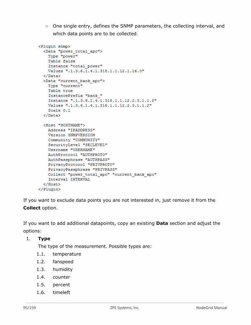
95/159 ZPE Systems, Inc. NodeGrid Manual
○ One single entry, defines the SNMP parameters, the collecting interval, and
which data points are to be collected.
If you want to exclude data points you are not interested in, just remove it from the
Collect option.
If you want to add additional datapoints, copy an existing Data section and adjust the
options:
1. Type
The type of the measurement. Possible types are:
1.1. temperature
1.2. fanspeed
1.3. humidity
1.4. counter
1.5. percent
1.6. timeleft
96/159 ZPE Systems, Inc. NodeGrid Manual
1.7. voltage
1.8. current
1.9. power
1.10. apparent_power
1.11. power_factor
1.12. frequency
2. Table
true: if the OID is part of a table.
false: if the OID corresponds to a single value.
This needs to be defined before Instance or Values
3. Instance
If Table is true: A SNMP OID prefix that will be walked to retrieve a list of names
that will be associated with the corresponding values. For example, in a PDU this
could be the outlet name.
If Table is false: The name [of the instance] that will be associated with the value,
as a string.
4. InstancePrefix
Optional. A string to the prepended to the Instance, enclosed in double quotes.
5. Values
If Table is true: The SNMP OID prefix that will be walked to retrieve a list of
values.
If Table is false: The SNMP OID used to retrieve a single value.
6. Scale
Optional. A decimal value to be multiplied to the value retrieved before persisting
it.
Except for Table and Scale, all others must be between double quotes.
13.1.2 Discovery Template
The ‘discover’ template for IPMI will automatically discover all the sensors available.
The template will have only one subsection, Host, and the options of interest are:
1. AuthType
The authentication type for the IPMI protocol. The default is to negotiate the
strongest one. Possible values are:
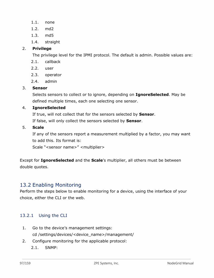
97/159 ZPE Systems, Inc. NodeGrid Manual
1.1. none
1.2. md2
1.3. md5
1.4. straight
2. Privilege
The privilege level for the IPMI protocol. The default is admin. Possible values are:
2.1. callback
2.2. user
2.3. operator
2.4. admin
3. Sensor
Selects sensors to collect or to ignore, depending on IgnoreSelected. May be
defined multiple times, each one selecting one sensor.
4. IgnoreSelected
If true, will not collect that for the sensors selected by Sensor.
If false, will only collect the sensors selected by Sensor.
5. Scale
If any of the sensors report a measurement multiplied by a factor, you may want
to add this. Its format is:
Scale “<sensor name>” <multiplier>
Except for IgnoreSelected and the Scale’s multiplier, all others must be between
double quotes.
13.2 Enabling Monitoring Perform the steps below to enable monitoring for a device, using the interface of your
choice, either the CLI or the web.
13.2.1 Using the CLI
1. Go to the device’s management settings:
cd /settings/devices/<device_name>/management/
2. Configure monitoring for the applicable protocol:
2.1. SNMP:
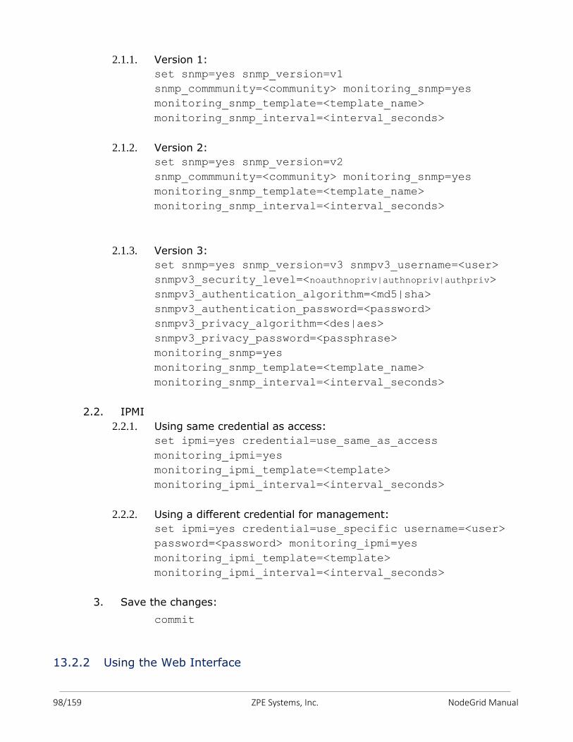
98/159 ZPE Systems, Inc. NodeGrid Manual
2.1.1. Version 1:
set snmp=yes snmp_version=v1
snmp_commmunity=<community> monitoring_snmp=yes
monitoring_snmp_template=<template_name>
monitoring_snmp_interval=<interval_seconds>
2.1.2. Version 2:
set snmp=yes snmp_version=v2
snmp_commmunity=<community> monitoring_snmp=yes
monitoring_snmp_template=<template_name>
monitoring_snmp_interval=<interval_seconds>
2.1.3. Version 3:
set snmp=yes snmp_version=v3 snmpv3_username=<user>
snmpv3_security_level=<noauthnopriv|authnopriv|authpriv>
snmpv3_authentication_algorithm=<md5|sha>
snmpv3_authentication_password=<password>
snmpv3_privacy_algorithm=<des|aes>
snmpv3_privacy_password=<passphrase>
monitoring_snmp=yes
monitoring_snmp_template=<template_name>
monitoring_snmp_interval=<interval_seconds>
2.2. IPMI
2.2.1. Using same credential as access:
set ipmi=yes credential=use_same_as_access
monitoring_ipmi=yes
monitoring_ipmi_template=<template>
monitoring_ipmi_interval=<interval_seconds>
2.2.2. Using a different credential for management:
set ipmi=yes credential=use_specific username=<user>
password=<password> monitoring_ipmi=yes
monitoring_ipmi_template=<template>
monitoring_ipmi_interval=<interval_seconds>
3. Save the changes:
commit
13.2.2 Using the Web Interface
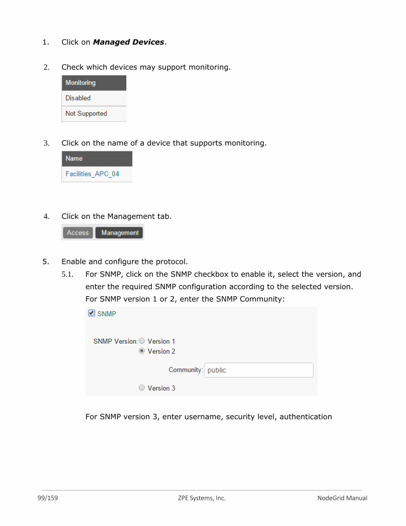
99/159 ZPE Systems, Inc. NodeGrid Manual
1. Click on Managed Devices.
2. Check which devices may support monitoring.
3. Click on the name of a device that supports monitoring.
4. Click on the Management tab.
5. Enable and configure the protocol.
5.1. For SNMP, click on the SNMP checkbox to enable it, select the version, and
enter the required SNMP configuration according to the selected version.
For SNMP version 1 or 2, enter the SNMP Community:
For SNMP version 3, enter username, security level, authentication
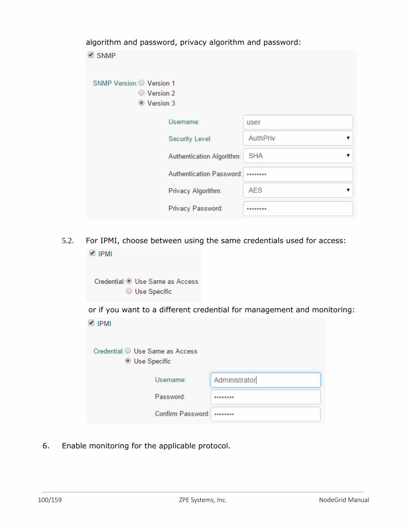
100/159 ZPE Systems, Inc. NodeGrid Manual
algorithm and password, privacy algorithm and password:
5.2. For IPMI, choose between using the same credentials used for access:
or if you want to a different credential for management and monitoring:
6. Enable monitoring for the applicable protocol.
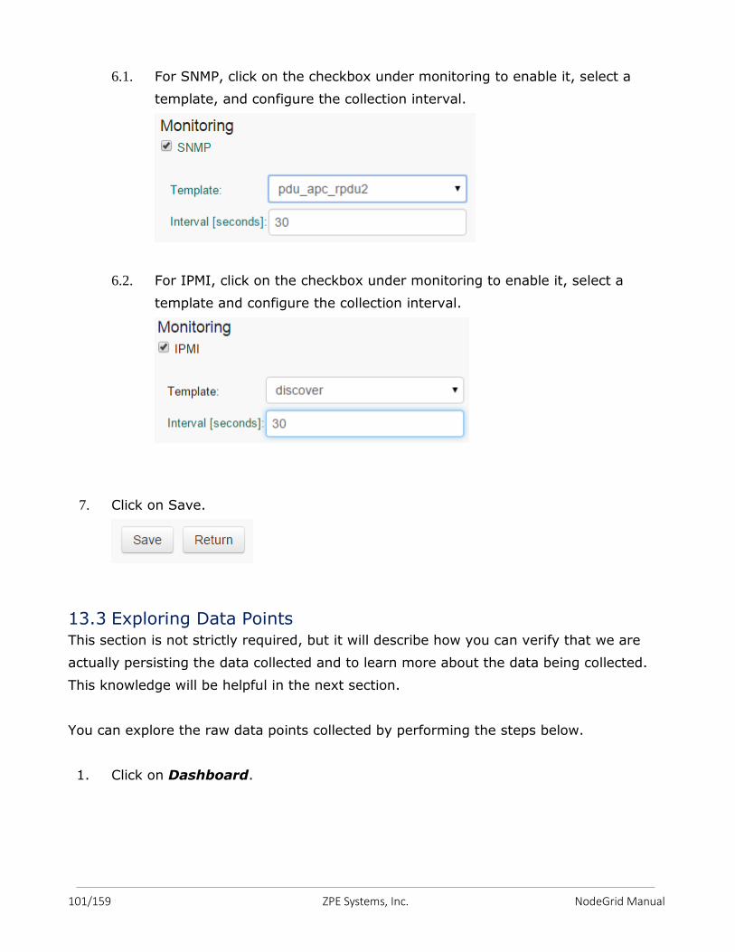
101/159 ZPE Systems, Inc. NodeGrid Manual
6.1. For SNMP, click on the checkbox under monitoring to enable it, select a
template, and configure the collection interval.
6.2. For IPMI, click on the checkbox under monitoring to enable it, select a
template and configure the collection interval.
7. Click on Save.
13.3 Exploring Data Points This section is not strictly required, but it will describe how you can verify that we are
actually persisting the data collected and to learn more about the data being collected.
This knowledge will be helpful in the next section.
You can explore the raw data points collected by performing the steps below.
1. Click on Dashboard.
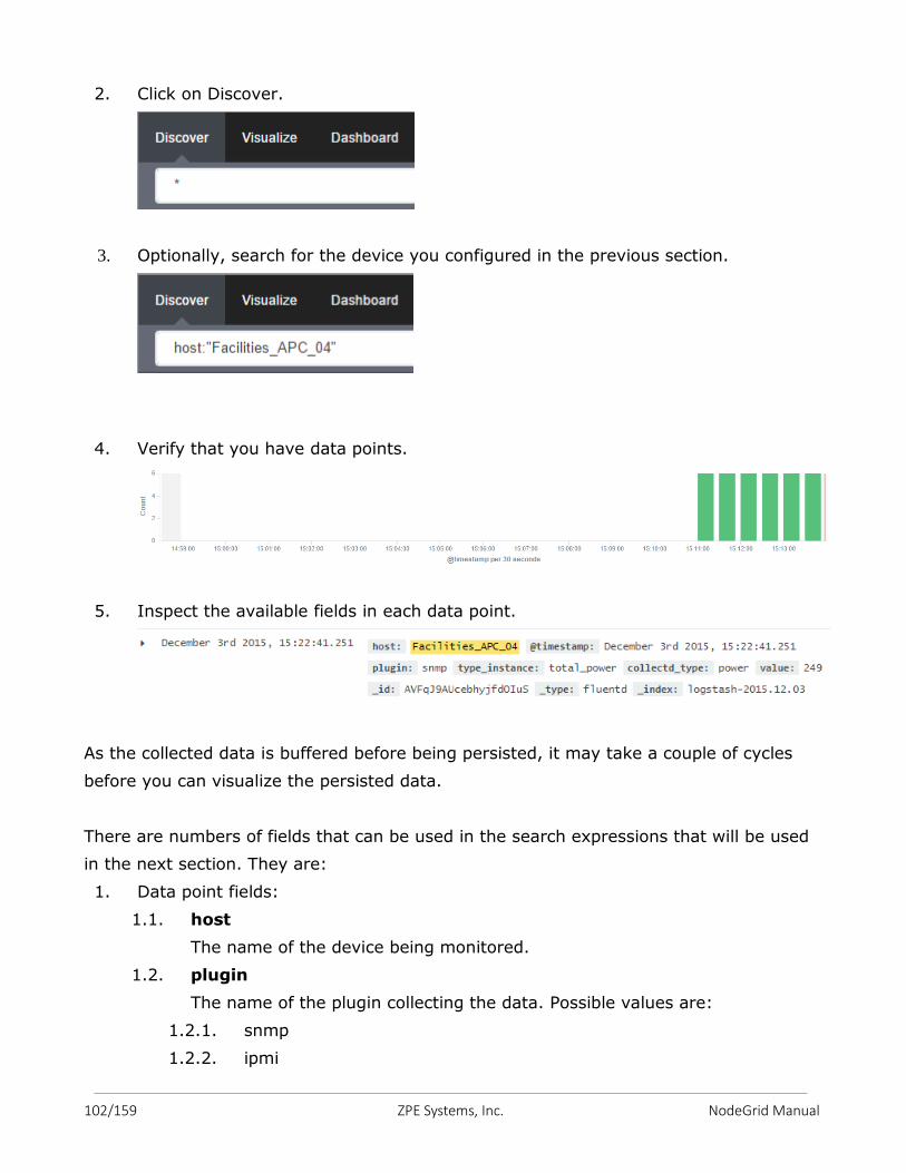
102/159 ZPE Systems, Inc. NodeGrid Manual
2. Click on Discover.
3. Optionally, search for the device you configured in the previous section.
4. Verify that you have data points.
5. Inspect the available fields in each data point.
As the collected data is buffered before being persisted, it may take a couple of cycles
before you can visualize the persisted data.
There are numbers of fields that can be used in the search expressions that will be used
in the next section. They are:
1. Data point fields:
1.1. host
The name of the device being monitored.
1.2. plugin
The name of the plugin collecting the data. Possible values are:
1.2.1. snmp
1.2.2. ipmi
103/159 ZPE Systems, Inc. NodeGrid Manual
1.2.3. nominal
1.2.4. aggregation
1.3. plugin_instance
The instance of the plugin collecting the data, if the plugin requires it.
Present in the aggregation plugin, possible values are:
1.3.1. sum
1.3.2. average
1.4. collectd_type
The type of the measurement. Possible values are:
1.4.1. temperature
1.4.2. humidity
1.4.3. fanspeed
1.4.4. timeleft
1.4.5. power
1.4.6. apparent_power
1.4.7. power_factor
1.4.8. current
1.4.9. voltage
1.4.10. frequency
1.4.11. percent
1.4.12. counter
1.5. type_instance
The name of the element associated with the measurement. For example, a
PDU’s outlet or bank would show up as type_instance.
2. Device fields:
2.1. name
The name of the device being monitored.
2.2. mode
The operational mode of the device. Possible value are:
2.2.1. enabled
2.2.2. ondemand
2.2.3. disabled
2.3. type
The type of the device. Possible values are:
2.3.1. ilo
2.3.2. drac
104/159 ZPE Systems, Inc. NodeGrid Manual
2.3.3. idrac6
2.3.4. ipmi_1.5
2.3.5. ipmi_2.0
2.3.6. cimc_ucs
2.3.7. device_console
2.3.8. pdu_apc
2.3.9. pdu_mph2
2.3.10. pdu_pm3000
2.3.11. pdu_raritan
2.3.12. pdu_servertech
2.3.13. pdu_enconnex
2.4. family
The family to which the device is a member. Possible values are:
2.4.1. ilo
2.4.2. drac
2.4.3. ipmi_1.5
2.4.4. ipmi_2.0
2.4.5. cimc_ucs
2.4.6. device_console
2.4.7. pdu
2.5. addr_location
The configured location for the device.
2.6. coordinates
The coordinates for the device.
2.7. ip
The IP address of the device.
2.8. mac
The mac address of the device, if known.
As MAC addresses have colon in its address, which is understood by the
query syntax to separate the field name from its field value, we will need to
escape it:
"00\\:02\\:99\\:11\\:B7\\:1D"
2.9. alias
The IP address alias assigned to the device.
2.10. groups
The authorization groups to which access to this device have been granted.
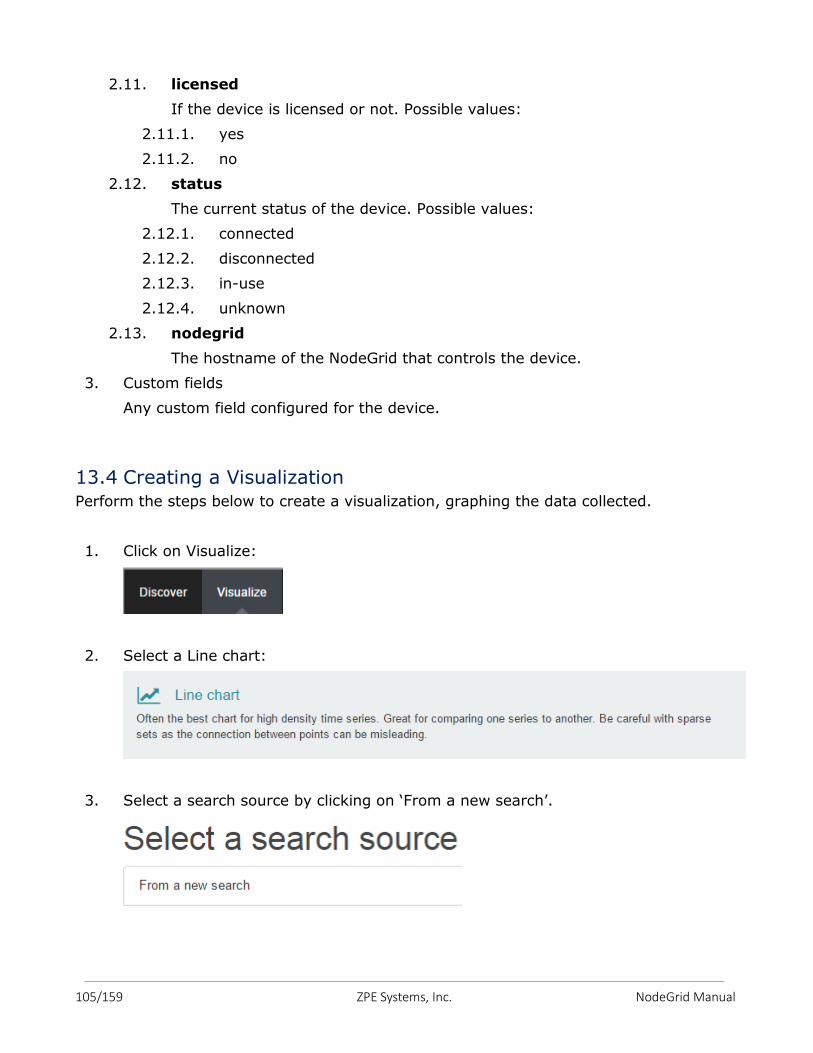
105/159 ZPE Systems, Inc. NodeGrid Manual
2.11. licensed
If the device is licensed or not. Possible values:
2.11.1. yes
2.11.2. no
2.12. status
The current status of the device. Possible values:
2.12.1. connected
2.12.2. disconnected
2.12.3. in-use
2.12.4. unknown
2.13. nodegrid
The hostname of the NodeGrid that controls the device.
3. Custom fields
Any custom field configured for the device.
13.4 Creating a Visualization Perform the steps below to create a visualization, graphing the data collected.
1. Click on Visualize:
2. Select a Line chart:
3. Select a search source by clicking on ‘From a new search’.
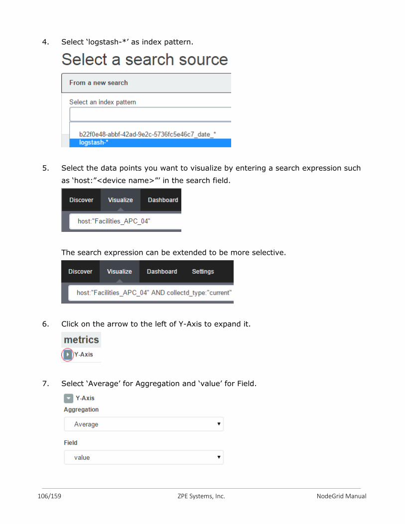
106/159 ZPE Systems, Inc. NodeGrid Manual
4. Select ‘logstash-*’ as index pattern.
5. Select the data points you want to visualize by entering a search expression such
as ‘host:”<device name>”’ in the search field.
The search expression can be extended to be more selective.
6. Click on the arrow to the left of Y-Axis to expand it.
7. Select ‘Average’ for Aggregation and ‘value’ for Field.
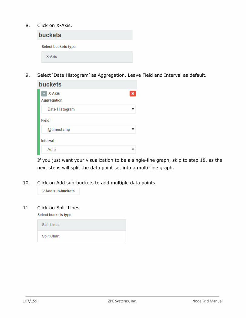
107/159 ZPE Systems, Inc. NodeGrid Manual
8. Click on X-Axis.
9. Select ‘Date Histogram’ as Aggregation. Leave Field and Interval as default.
If you just want your visualization to be a single-line graph, skip to step 18, as the
next steps will split the data point set into a multi-line graph.
10. Click on Add sub-buckets to add multiple data points.
11. Click on Split Lines.
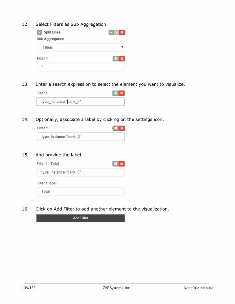
108/159 ZPE Systems, Inc. NodeGrid Manual
12. Select Filters as Sub Aggregation.
13. Enter a search expression to select the element you want to visualize.
14. Optionally, associate a label by clicking on the settings icon,
15. And provide the label.
16. Click on Add Filter to add another element to the visualization.
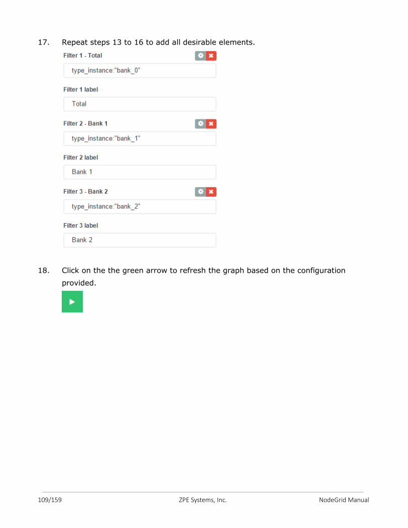
109/159 ZPE Systems, Inc. NodeGrid Manual
17. Repeat steps 13 to 16 to add all desirable elements.
18. Click on the the green arrow to refresh the graph based on the configuration
provided.
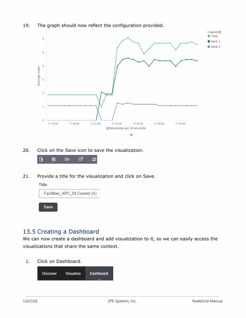
110/159 ZPE Systems, Inc. NodeGrid Manual
19. The graph should now reflect the configuration provided.
20. Click on the Save icon to save the visualization.
21. Provide a title for the visualization and click on Save.
13.5 Creating a Dashboard We can now create a dashboard and add visualization to it, so we can easily access the
visualizations that share the same context.
1. Click on Dashboard.
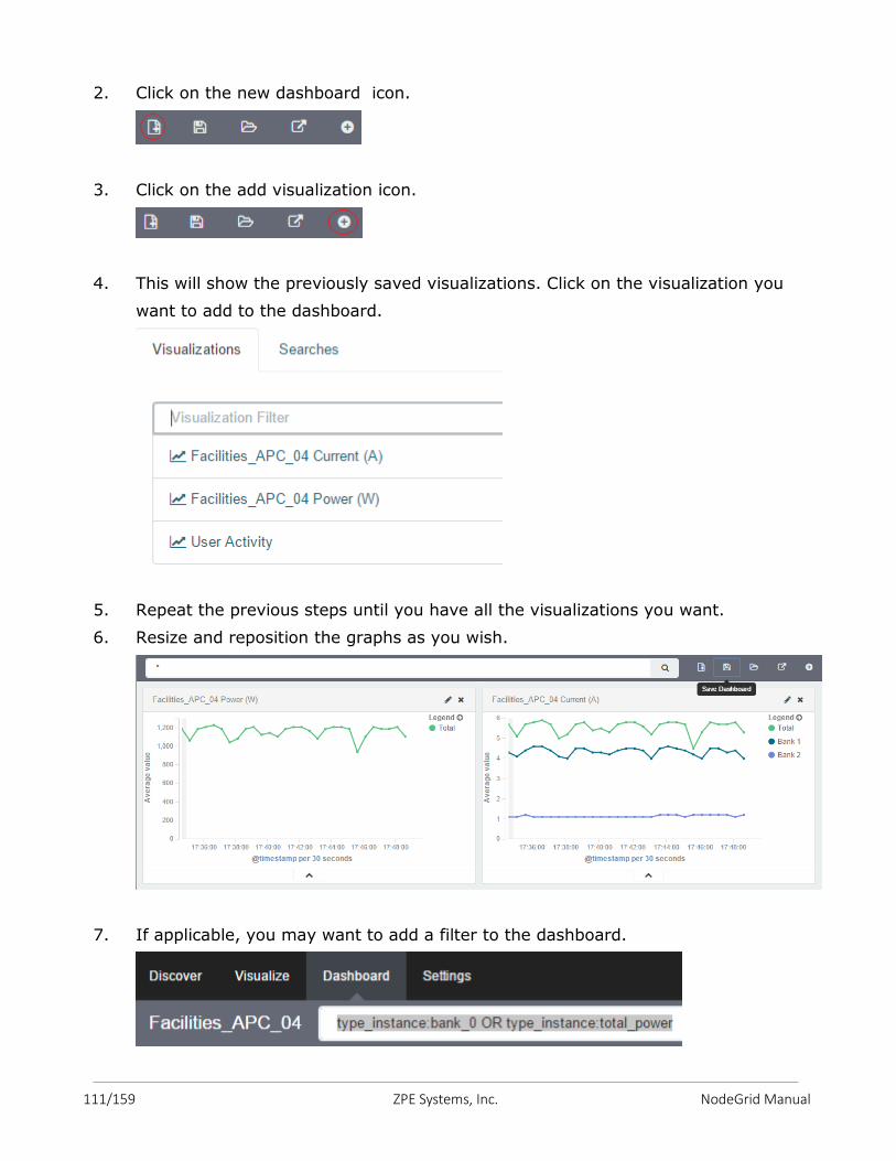
111/159 ZPE Systems, Inc. NodeGrid Manual
2. Click on the new dashboard icon.
3. Click on the add visualization icon.
4. This will show the previously saved visualizations. Click on the visualization you
want to add to the dashboard.
5. Repeat the previous steps until you have all the visualizations you want.
6. Resize and reposition the graphs as you wish.
7. If applicable, you may want to add a filter to the dashboard.
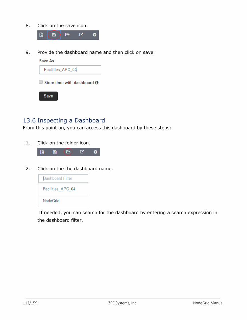
112/159 ZPE Systems, Inc. NodeGrid Manual
8. Click on the save icon.
9. Provide the dashboard name and then click on save.
13.6 Inspecting a Dashboard From this point on, you can access this dashboard by these steps:
1. Click on the folder icon.
2. Click on the the dashboard name.
If needed, you can search for the dashboard by entering a search expression in
the dashboard filter.
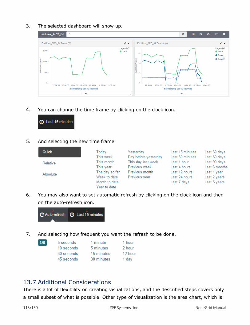
113/159 ZPE Systems, Inc. NodeGrid Manual
3. The selected dashboard will show up.
4. You can change the time frame by clicking on the clock icon.
5. And selecting the new time frame.
6. You may also want to set automatic refresh by clicking on the clock icon and then
on the auto-refresh icon.
7. And selecting how frequent you want the refresh to be done.
13.7 Additional Considerations There is a lot of flexibility on creating visualizations, and the described steps covers only
a small subset of what is possible. Other type of visualization is the area chart, which is
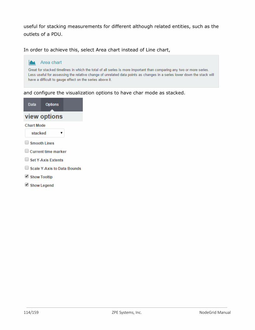
114/159 ZPE Systems, Inc. NodeGrid Manual
useful for stacking measurements for different although related entities, such as the
outlets of a PDU.
In order to achieve this, select Area chart instead of Line chart,
and configure the visualization options to have char mode as stacked.
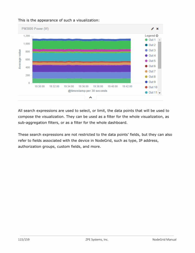
115/159 ZPE Systems, Inc. NodeGrid Manual
This is the appearance of such a visualization:
All search expressions are used to select, or limit, the data points that will be used to
compose the visualization. They can be used as a filter for the whole visualization, as
sub-aggregation filters, or as a filter for the whole dashboard.
These search expressions are not restricted to the data points’ fields, but they can also
refer to fields associated with the device in NodeGrid, such as type, IP address,
authorization groups, custom fields, and more.
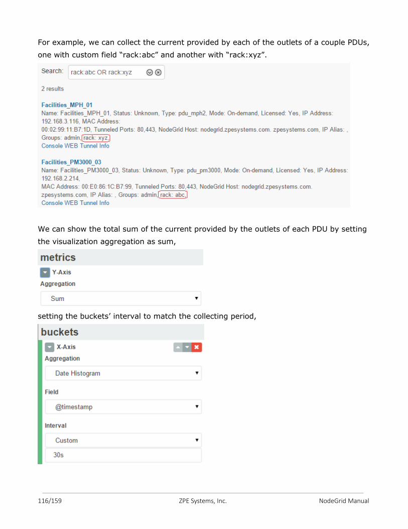
116/159 ZPE Systems, Inc. NodeGrid Manual
For example, we can collect the current provided by each of the outlets of a couple PDUs,
one with custom field “rack:abc” and another with “rack:xyz”.
We can show the total sum of the current provided by the outlets of each PDU by setting
the visualization aggregation as sum,
setting the buckets’ interval to match the collecting period,
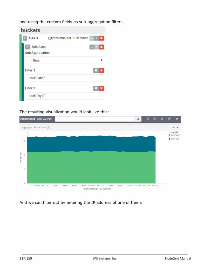
117/159 ZPE Systems, Inc. NodeGrid Manual
and using the custom fields as sub-aggregation filters.
The resulting visualization would look like this:
And we can filter out by entering the IP address of one of them:

118/159 ZPE Systems, Inc. NodeGrid Manual
We can further filter out to get a single outlet, all from the same visualization.
However, we need to be careful to not account for the same measurement twice, like
mixing power consumers and power producers, or a PDU’s input and output power.
119/159 ZPE Systems, Inc. NodeGrid Manual
The Applications option will be available once the Docker is installed.
Docker is an open platform for building, shipping and running distributed applications. It
gives programmers, development teams and operations engineers the common toolbox
they need to take advantage of the distributed and networked nature of modern
applications.
Docker uses a client-server architecture. The Docker client talks to the Docker daemon,
which does the heavy lifting of building, running, and distributing your Docker containers.
Both the Docker client and the daemon can run on the same system, or you can connect
a Docker client to a remote Docker daemon. The Docker client and daemon communicate
via sockets or through a RESTful API.
Docker have 3 components: images, registries and containers. An image is used to
create Docker containers. A Docker image is just a template, and this template can hold
a Linux operating system, as Ubuntu, or other files inside. Also, you can build you own
image by creating a Dockerfile. Dockerfile is a "recipe" that will be parsed/executed by
Docker, and the result will be a brand new Docker image.
A registry is an image repository. A registry can hold a lot of different type of images, for
different purposes and use cases. If you just want to use a image (e.g. Ubuntu), you can
just download the Ubuntu image from a registry and thus create your container based on
it. Docker Hub is the default registry that will be used to search for a image using the
Docker client.
Containers is a process that will run an application. A container is based on a image, and
will hold all necessary data to be able to run your application. Containers are like Virtual
Machines is some aspects: they can be started, stopped, moved and deleted. But, as a
containers run as a host OS process, they are much lighter and faster than Virtual
Machines.
14. APPLICATIONS
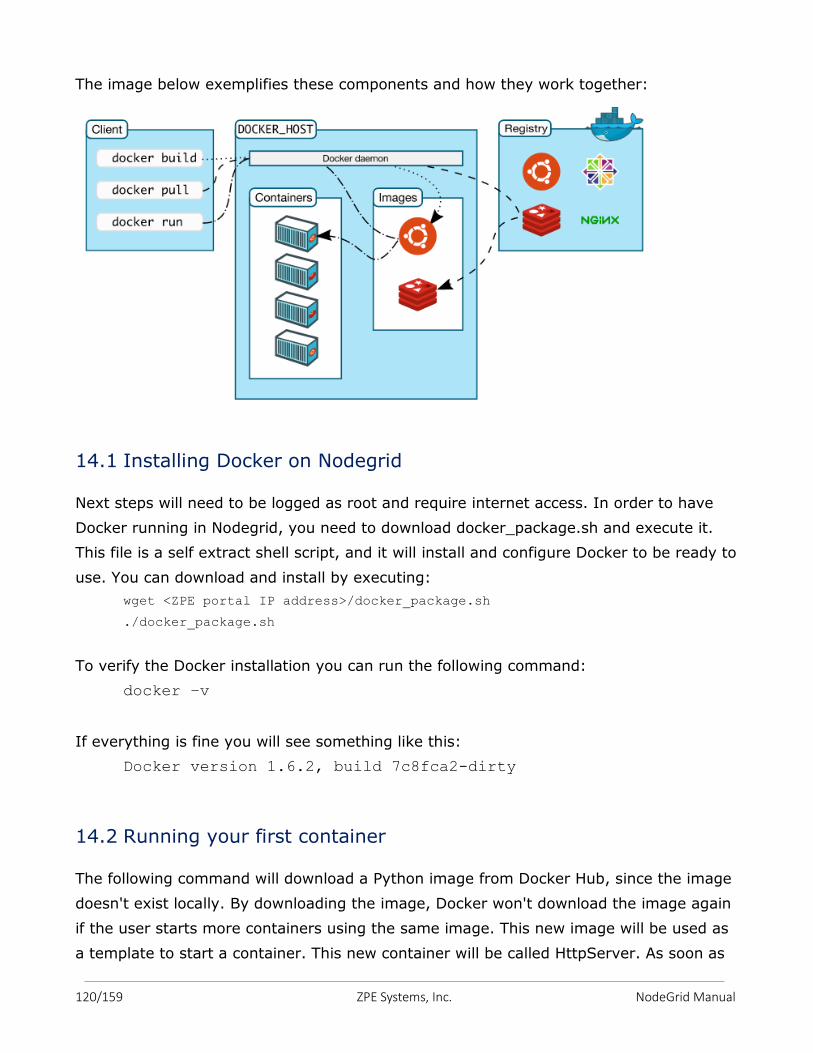
120/159 ZPE Systems, Inc. NodeGrid Manual
The image below exemplifies these components and how they work together:
14.1 Installing Docker on Nodegrid
Next steps will need to be logged as root and require internet access. In order to have
Docker running in Nodegrid, you need to download docker_package.sh and execute it.
This file is a self extract shell script, and it will install and configure Docker to be ready to
use. You can download and install by executing:
wget <ZPE portal IP address>/docker_package.sh
./docker_package.sh
To verify the Docker installation you can run the following command:
docker –v
If everything is fine you will see something like this:
Docker version 1.6.2, build 7c8fca2-dirty
14.2 Running your first container
The following command will download a Python image from Docker Hub, since the image
doesn't exist locally. By downloading the image, Docker won't download the image again
if the user starts more containers using the same image. This new image will be used as
a template to start a container. This new container will be called HttpServer. As soon as
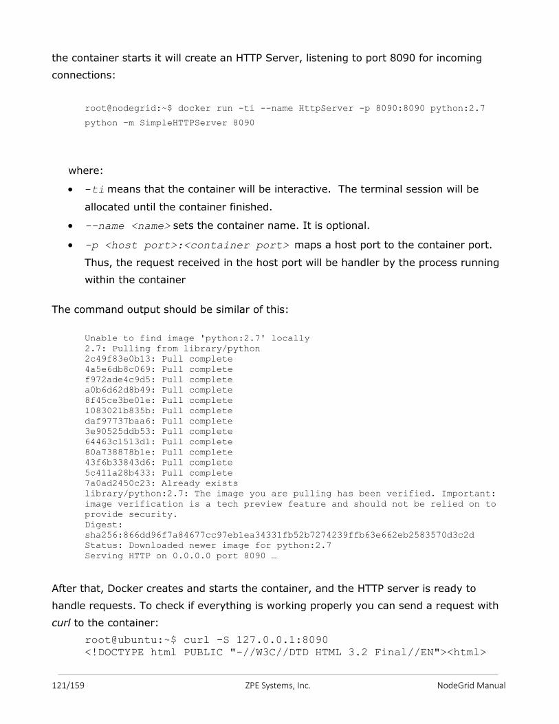
121/159 ZPE Systems, Inc. NodeGrid Manual
the container starts it will create an HTTP Server, listening to port 8090 for incoming
connections:
root@nodegrid:~$ docker run -ti --name HttpServer -p 8090:8090 python:2.7
python -m SimpleHTTPServer 8090
where:
-ti means that the container will be interactive. The terminal session will be
allocated until the container finished.
--name <name> sets the container name. It is optional.
-p <host port>:<container port> maps a host port to the container port.
Thus, the request received in the host port will be handler by the process running
within the container
The command output should be similar of this:
Unable to find image 'python:2.7' locally 2.7: Pulling from library/python 2c49f83e0b13: Pull complete 4a5e6db8c069: Pull complete f972ade4c9d5: Pull complete a0b6d62d8b49: Pull complete 8f45ce3be01e: Pull complete 1083021b835b: Pull complete daf97737baa6: Pull complete 3e90525ddb53: Pull complete 64463c1513d1: Pull complete 80a738878b1e: Pull complete 43f6b33843d6: Pull complete 5c411a28b433: Pull complete 7a0ad2450c23: Already exists library/python:2.7: The image you are pulling has been verified. Important:
image verification is a tech preview feature and should not be relied on to
provide security. Digest:
sha256:866dd96f7a84677cc97eb1ea34331fb52b7274239ffb63e662eb2583570d3c2d Status: Downloaded newer image for python:2.7 Serving HTTP on 0.0.0.0 port 8090 …
After that, Docker creates and starts the container, and the HTTP server is ready to
handle requests. To check if everything is working properly you can send a request with
curl to the container:
root@ubuntu:~$ curl -S 127.0.0.1:8090 <!DOCTYPE html PUBLIC "-//W3C//DTD HTML 3.2 Final//EN"><html>
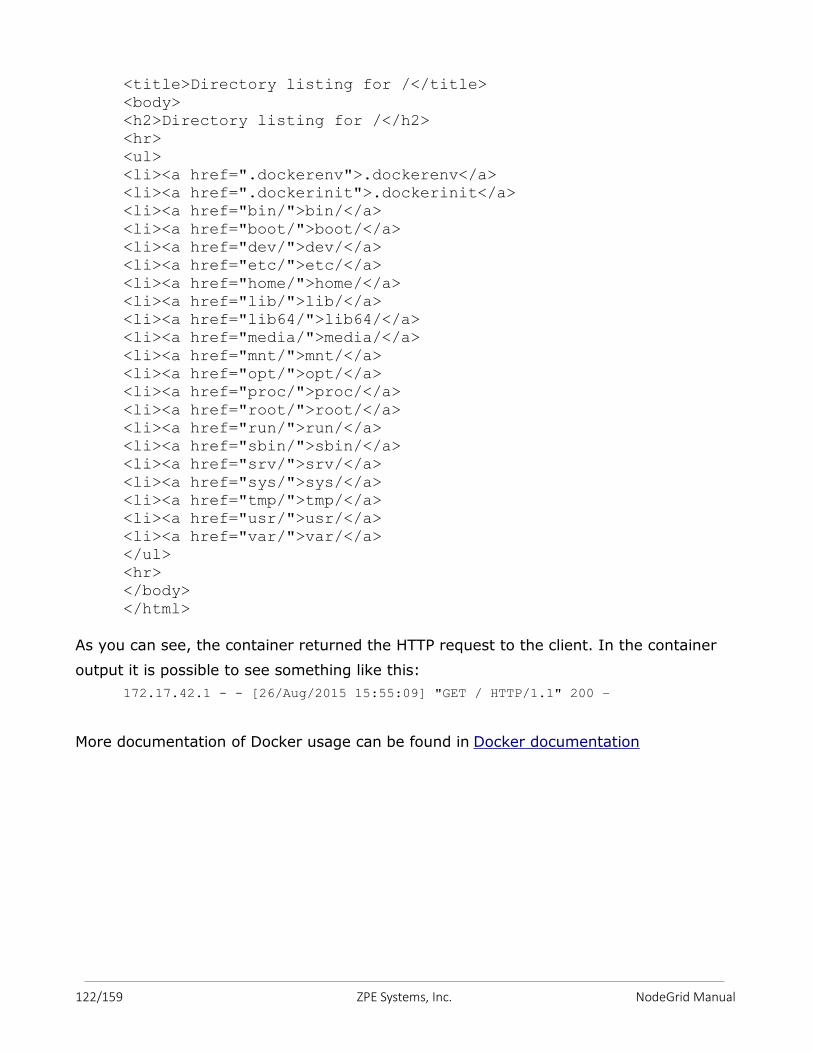
122/159 ZPE Systems, Inc. NodeGrid Manual
<title>Directory listing for /</title>
<body> <h2>Directory listing for /</h2> <hr>
<ul> <li><a href=".dockerenv">.dockerenv</a> <li><a href=".dockerinit">.dockerinit</a> <li><a href="bin/">bin/</a>
<li><a href="boot/">boot/</a> <li><a href="dev/">dev/</a> <li><a href="etc/">etc/</a>
<li><a href="home/">home/</a> <li><a href="lib/">lib/</a> <li><a href="lib64/">lib64/</a> <li><a href="media/">media/</a>
<li><a href="mnt/">mnt/</a> <li><a href="opt/">opt/</a> <li><a href="proc/">proc/</a>
<li><a href="root/">root/</a> <li><a href="run/">run/</a> <li><a href="sbin/">sbin/</a> <li><a href="srv/">srv/</a>
<li><a href="sys/">sys/</a> <li><a href="tmp/">tmp/</a> <li><a href="usr/">usr/</a>
<li><a href="var/">var/</a> </ul> <hr> </body>
</html>
As you can see, the container returned the HTTP request to the client. In the container
output it is possible to see something like this:
172.17.42.1 - - [26/Aug/2015 15:55:09] "GET / HTTP/1.1" 200 –
More documentation of Docker usage can be found in Docker documentation
123/159 ZPE Systems, Inc. NodeGrid Manual
Our Technical Support staff are standing by to provide assistance in case you have any
operational or installation issues regarding to your licensed NodeGrid product. In order to
be assisted in the fastest way possible, follow the steps below:
1. Verify the relevant section of this manual to see if the problem can be solved by
following the recommended procedures shown;
2. For Online help documentation, go to www.support.zpesystems.com
3. Visit our Help Center Website http://www.zpesystems.com/resources/help-center
for our Knowledge Base or to submit an online ticket request for support help per
steps below:
a. click on ‘Submit a request’ link on the top right corner of the page.
b. Enter the required information on the request form. Provide as much detailed
information as possible on description of the problem or question.
c. If there is any attachment, add a file or drop the file in the dropping area.
d. Check the "I'm not a robot" checkbox.
e. Click on Submit
You will receive an email from ZPE Systems confirming that your request (your ticket number) has been received and being reviewed by our support staff.
To automatically receive information about important security patch announcements,
future firmware updates and other technical information, sign up here:
http://zpesystems.com/loop/
TECHNICAL SUPPORT
124/159 ZPE Systems, Inc. NodeGrid Manual
How to recover/reset password of admin or root users
Case #1
The admin password was changed and you don’t remember it, but root password is still
the default.
Log in as root via NodeGrid console port, type its default password root. At the shell
prompt, type passwd admin and enter the new password. You should be able to log in as
admin with the new password.
Case #2
The root password was changed, but admin has still the default password.
Log in as admin via ssh, telnet, or console. At the admin cli prompt, type: shell sudo su -
It should present the root shell prompt. Then type passwd root and enter the new
password. You should be able to log in as root with the new password.
Case #3
Both admin and root passwords were changed and you don’t remember them.
Follow the steps below:
a) Have a terminal (Putty, SecureCRT) with 115200bps baud rate connected to the
NodeGrid console port, or a monitor to the HDMI and a keyboard to USB port, if
you have the NodeGrid Serial Console; or launch the Remote Console on the VM, if
you have the NodeGrid Manager.
b) Reboot the NodeGrid.
c) Select Rescue Mode at the bootloader menu:
APPENDIX A – Recovery Procedures
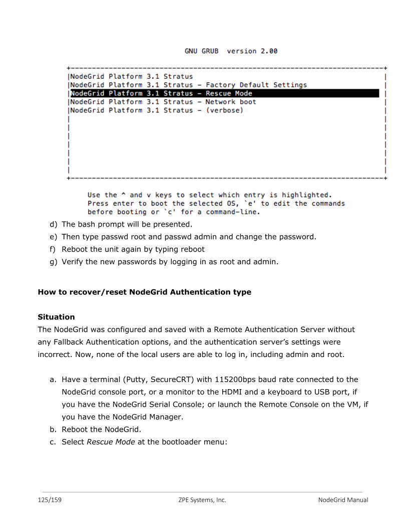
125/159 ZPE Systems, Inc. NodeGrid Manual
d) The bash prompt will be presented.
e) Then type passwd root and passwd admin and change the password.
f) Reboot the unit again by typing reboot
g) Verify the new passwords by logging in as root and admin.
How to recover/reset NodeGrid Authentication type
Situation
The NodeGrid was configured and saved with a Remote Authentication Server without
any Fallback Authentication options, and the authentication server’s settings were
incorrect. Now, none of the local users are able to log in, including admin and root.
a. Have a terminal (Putty, SecureCRT) with 115200bps baud rate connected to the
NodeGrid console port, or a monitor to the HDMI and a keyboard to USB port, if
you have the NodeGrid Serial Console; or launch the Remote Console on the VM, if
you have the NodeGrid Manager.
b. Reboot the NodeGrid.
c. Select Rescue Mode at the bootloader menu:
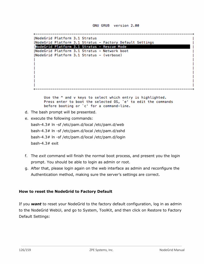
126/159 ZPE Systems, Inc. NodeGrid Manual
d. The bash prompt will be presented.
e. execute the following commands:
bash-4.3# ln -sf /etc/pam.d/local /etc/pam.d/web
bash-4.3# ln -sf /etc/pam.d/local /etc/pam.d/sshd
bash-4.3# ln -sf /etc/pam.d/local /etc/pam.d/login
bash-4.3# exit
f. The exit command will finish the normal boot process, and present you the login
prompt. You should be able to login as admin or root.
g. After that, please login again on the web interface as admin and reconfigure the
Authentication method, making sure the server’s settings are correct.
How to reset the NodeGrid to Factory Default
If you want to reset your NodeGrid to the factory default configuration, log in as admin
to the NodeGrid WebUi, and go to System, ToolKit, and then click on Restore to Factory
Default Settings:
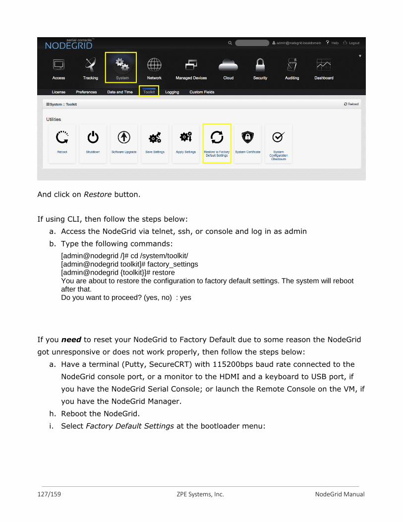
127/159 ZPE Systems, Inc. NodeGrid Manual
And click on Restore button.
If using CLI, then follow the steps below:
a. Access the NodeGrid via telnet, ssh, or console and log in as admin
b. Type the following commands:
[admin@nodegrid /]# cd /system/toolkit/ [admin@nodegrid toolkit]# factory_settings [admin@nodegrid {toolkit}]# restore You are about to restore the configuration to factory default settings. The system will reboot after that. Do you want to proceed? (yes, no) : yes
If you need to reset your NodeGrid to Factory Default due to some reason the NodeGrid
got unresponsive or does not work properly, then follow the steps below:
a. Have a terminal (Putty, SecureCRT) with 115200bps baud rate connected to the
NodeGrid console port, or a monitor to the HDMI and a keyboard to USB port, if
you have the NodeGrid Serial Console; or launch the Remote Console on the VM, if
you have the NodeGrid Manager.
h. Reboot the NodeGrid.
i. Select Factory Default Settings at the bootloader menu:
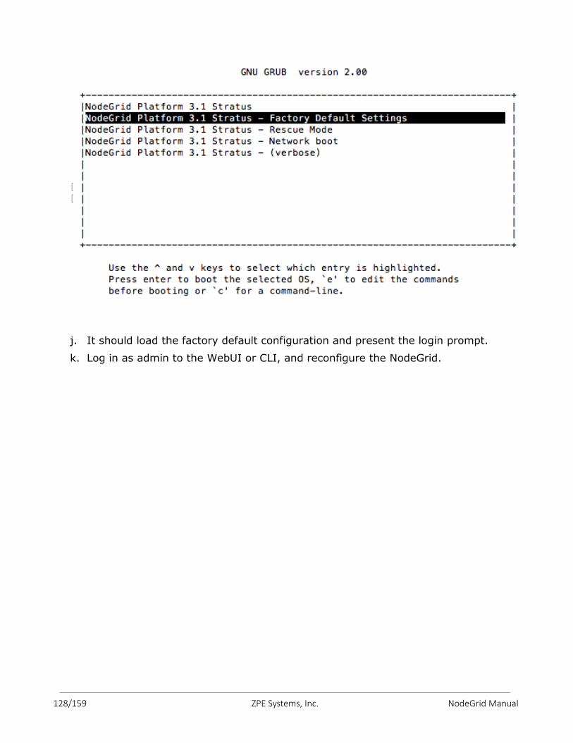
128/159 ZPE Systems, Inc. NodeGrid Manual
j. It should load the factory default configuration and present the login prompt.
k. Log in as admin to the WebUI or CLI, and reconfigure the NodeGrid.
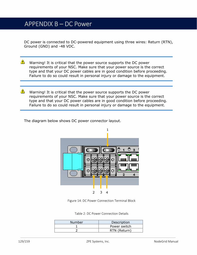
129/159 ZPE Systems, Inc. NodeGrid Manual
DC power is connected to DC-powered equipment using three wires: Return (RTN), Ground (GND) and -48 VDC.
The diagram below shows DC power connector layout.
Figure 14: DC Power Connection Terminal Block
Table 2: DC Power Connection Details
Number Description Number Description Number Description
1 Power switch
2 RTN (Return)
Warning! It is critical that the power source supports the DC power requirements of your NSC. Make sure that your power source is the correct type and that your DC power cables are in good condition before proceeding.
Failure to do so could result in personal injury or damage to the equipment.
Warning! It is critical that the power source supports the DC power requirements of your NSC. Make sure that your power source is the correct type and that your DC power cables are in good condition before proceeding.
Failure to do so could result in personal injury or damage to the equipment.
1
\
1
\
2
\
2
\
3
\
3
\
4
\
4
\
APPENDIX B – DC Power
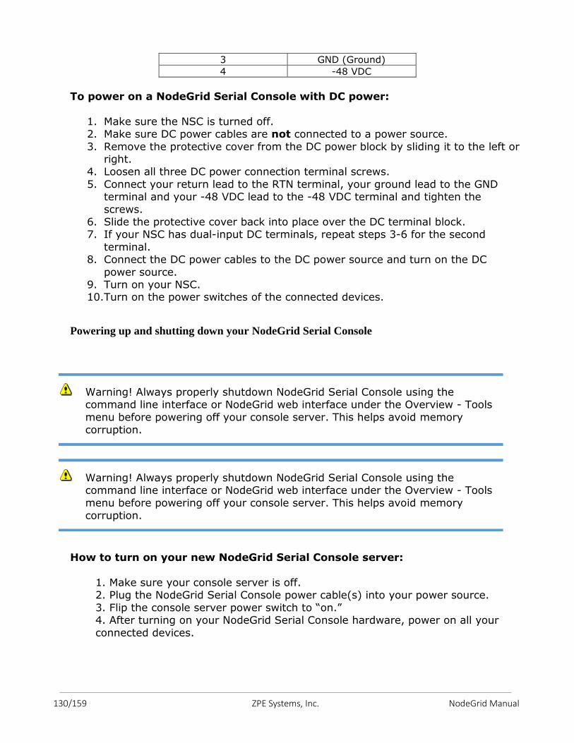
130/159 ZPE Systems, Inc. NodeGrid Manual
3 GND (Ground)
4 -48 VDC
To power on a NodeGrid Serial Console with DC power:
1. Make sure the NSC is turned off. 2. Make sure DC power cables are not connected to a power source.
3. Remove the protective cover from the DC power block by sliding it to the left or right.
4. Loosen all three DC power connection terminal screws.
5. Connect your return lead to the RTN terminal, your ground lead to the GND terminal and your -48 VDC lead to the -48 VDC terminal and tighten the
screws. 6. Slide the protective cover back into place over the DC terminal block. 7. If your NSC has dual-input DC terminals, repeat steps 3-6 for the second
terminal. 8. Connect the DC power cables to the DC power source and turn on the DC
power source. 9. Turn on your NSC. 10.Turn on the power switches of the connected devices.
Powering up and shutting down your NodeGrid Serial Console
How to turn on your new NodeGrid Serial Console server:
1. Make sure your console server is off. 2. Plug the NodeGrid Serial Console power cable(s) into your power source.
3. Flip the console server power switch to “on.” 4. After turning on your NodeGrid Serial Console hardware, power on all your
connected devices.
Warning! Always properly shutdown NodeGrid Serial Console using the command line interface or NodeGrid web interface under the Overview - Tools
menu before powering off your console server. This helps avoid memory
corruption.
Warning! Always properly shutdown NodeGrid Serial Console using the command line interface or NodeGrid web interface under the Overview - Tools
menu before powering off your console server. This helps avoid memory
corruption.
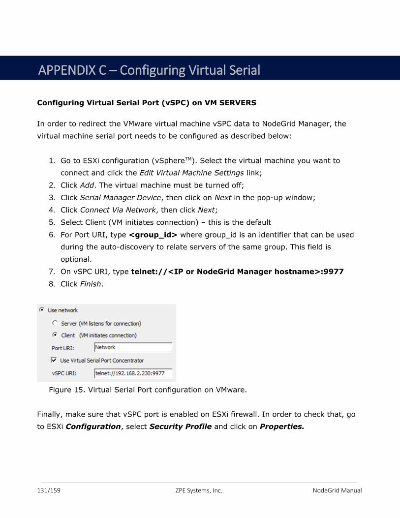
131/159 ZPE Systems, Inc. NodeGrid Manual
Configuring Virtual Serial Port (vSPC) on VM SERVERS
In order to redirect the VMware virtual machine vSPC data to NodeGrid Manager, the
virtual machine serial port needs to be configured as described below:
1. Go to ESXi configuration (vSphereTM). Select the virtual machine you want to
connect and click the Edit Virtual Machine Settings link;
2. Click Add. The virtual machine must be turned off;
3. Click Serial Manager Device, then click on Next in the pop-up window;
4. Click Connect Via Network, then click Next;
5. Select Client (VM initiates connection) – this is the default
6. For Port URI, type <group_id> where group_id is an identifier that can be used
during the auto-discovery to relate servers of the same group. This field is
optional.
7. On vSPC URI, type telnet://<IP or NodeGrid Manager hostname>:9977
8. Click Finish.
Figure 15. Virtual Serial Port configuration on VMware.
Finally, make sure that vSPC port is enabled on ESXi firewall. In order to check that, go
to ESXi Configuration, select Security Profile and click on Properties.
APPENDIX C – Configuring Virtual Serial Port on VMs
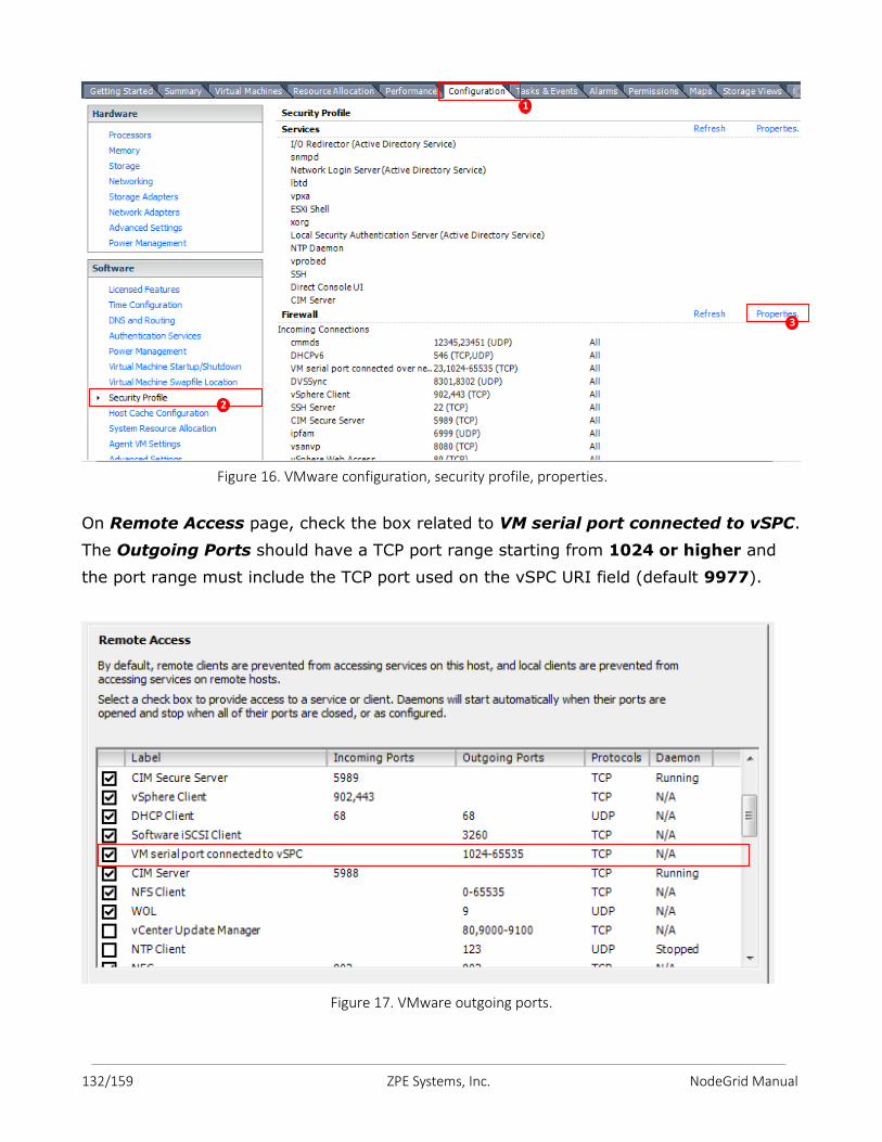
132/159 ZPE Systems, Inc. NodeGrid Manual
Figure 16. VMware configuration, security profile, properties.
On Remote Access page, check the box related to VM serial port connected to vSPC.
The Outgoing Ports should have a TCP port range starting from 1024 or higher and
the port range must include the TCP port used on the vSPC URI field (default 9977).
Figure 17. VMware outgoing ports.
1
1
2
A
P
P
E
N
D
I
X 2
3
3
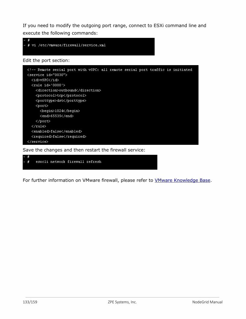
133/159 ZPE Systems, Inc. NodeGrid Manual
If you need to modify the outgoing port range, connect to ESXi command line and
execute the following commands:
Edit the port section:
Save the changes and then restart the firewall service:
For further information on VMware firewall, please refer to VMware Knowledge Base.
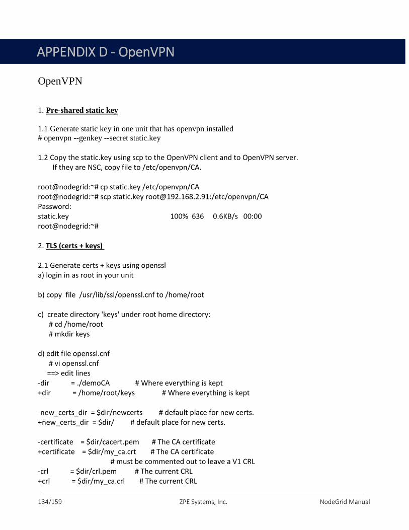
134/159 ZPE Systems, Inc. NodeGrid Manual
OpenVPN
1. Pre-shared static key
1.1 Generate static key in one unit that has openvpn installed
# openvpn --genkey --secret static.key
1.2 Copy the static.key using scp to the OpenVPN client and to OpenVPN server. If they are NSC, copy file to /etc/openvpn/CA. root@nodegrid:~# cp static.key /etc/openvpn/CA root@nodegrid:~# scp static.key [email protected]:/etc/openvpn/CA Password: static.key 100% 636 0.6KB/s 00:00 root@nodegrid:~# 2. TLS (certs + keys) 2.1 Generate certs + keys using openssl a) login in as root in your unit b) copy file /usr/lib/ssl/openssl.cnf to /home/root c) create directory 'keys' under root home directory: # cd /home/root # mkdir keys d) edit file openssl.cnf # vi openssl.cnf ==> edit lines -dir = ./demoCA # Where everything is kept +dir = /home/root/keys # Where everything is kept -new_certs_dir = $dir/newcerts # default place for new certs. +new_certs_dir = $dir/ # default place for new certs. -certificate = $dir/cacert.pem # The CA certificate +certificate = $dir/my_ca.crt # The CA certificate # must be commented out to leave a V1 CRL -crl = $dir/crl.pem # The current CRL +crl = $dir/my_ca.crl # The current CRL
APPENDIX D - OpenVPN
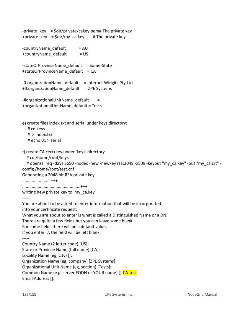
135/159 ZPE Systems, Inc. NodeGrid Manual
-private_key = $dir/private/cakey.pem# The private key +private_key = $dir/my_ca.key # The private key -countryName_default = AU +countryName_default = US -stateOrProvinceName_default = Some-State +stateOrProvinceName_default = CA -0.organizationName_default = Internet Widgits Pty Ltd +0.organizationName_default = ZPE Systems -#organizationalUnitName_default = +organizationalUnitName_default = Tests e) create files index.txt and serial under keys directory: # cd keys # > index.txt # echo 01 > serial f) create CA cert+key under 'keys' directory # cd /home/root/keys # openssl req -days 3650 -nodes -new -newkey rsa:2048 -x509 -keyout "my_ca.key" -out "my_ca.crt" -config /home/root/test.cnf Generating a 2048 bit RSA private key ........................+++ .................................................+++ writing new private key to 'my_ca.key' ----- You are about to be asked to enter information that will be incorporated into your certificate request. What you are about to enter is what is called a Distinguished Name or a DN. There are quite a few fields but you can leave some blank For some fields there will be a default value, If you enter '.', the field will be left blank. ----- Country Name (2 letter code) [US]: State or Province Name (full name) [CA]: Locality Name (eg, city) []: Organization Name (eg, company) [ZPE Systems]: Organizational Unit Name (eg, section) [Tests]: Common Name (e.g. server FQDN or YOUR name) []:CA-test Email Address []:
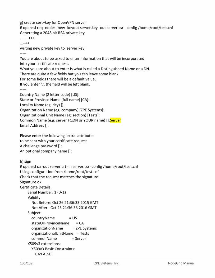
136/159 ZPE Systems, Inc. NodeGrid Manual
g) create cert+key for OpenVPN server # openssl req -nodes -new -keyout server.key -out server.csr -config /home/root/test.cnf Generating a 2048 bit RSA private key ........+++ ...+++ writing new private key to 'server.key' ----- You are about to be asked to enter information that will be incorporated into your certificate request. What you are about to enter is what is called a Distinguished Name or a DN. There are quite a few fields but you can leave some blank For some fields there will be a default value, If you enter '.', the field will be left blank. ----- Country Name (2 letter code) [US]: State or Province Name (full name) [CA]: Locality Name (eg, city) []: Organization Name (eg, company) [ZPE Systems]: Organizational Unit Name (eg, section) [Tests]: Common Name (e.g. server FQDN or YOUR name) []:Server Email Address []: Please enter the following 'extra' attributes to be sent with your certificate request A challenge password []: An optional company name []: h) sign # openssl ca -out server.crt -in server.csr -config /home/root/test.cnf Using configuration from /home/root/test.cnf Check that the request matches the signature Signature ok Certificate Details: Serial Number: 1 (0x1) Validity Not Before: Oct 26 21:36:33 2015 GMT Not After : Oct 25 21:36:33 2016 GMT Subject: countryName = US stateOrProvinceName = CA organizationName = ZPE Systems organizationalUnitName = Tests commonName = Server X509v3 extensions: X509v3 Basic Constraints: CA:FALSE
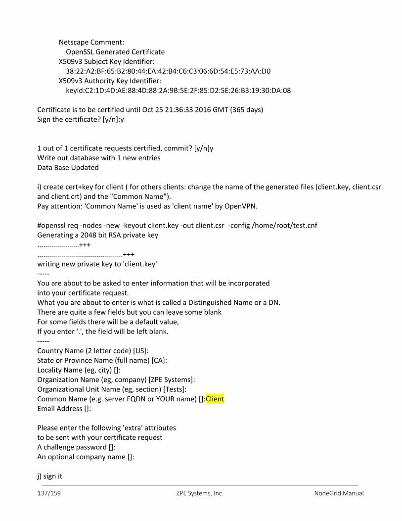
137/159 ZPE Systems, Inc. NodeGrid Manual
Netscape Comment: OpenSSL Generated Certificate X509v3 Subject Key Identifier: 38:22:A2:BF:65:B2:80:44:EA:42:B4:C6:C3:06:6D:54:E5:73:AA:D0 X509v3 Authority Key Identifier: keyid:C2:1D:4D:AE:88:4D:88:2A:9B:5E:2F:85:D2:5E:26:B3:19:30:DA:08 Certificate is to be certified until Oct 25 21:36:33 2016 GMT (365 days) Sign the certificate? [y/n]:y 1 out of 1 certificate requests certified, commit? [y/n]y Write out database with 1 new entries Data Base Updated i) create cert+key for client ( for others clients: change the name of the generated files (client.key, client.csr and client.crt) and the "Common Name"). Pay attention: 'Common Name' is used as 'client name' by OpenVPN. #openssl req -nodes -new -keyout client.key -out client.csr -config /home/root/test.cnf Generating a 2048 bit RSA private key .....................+++ ...........................................+++ writing new private key to 'client.key' ----- You are about to be asked to enter information that will be incorporated into your certificate request. What you are about to enter is what is called a Distinguished Name or a DN. There are quite a few fields but you can leave some blank For some fields there will be a default value, If you enter '.', the field will be left blank. ----- Country Name (2 letter code) [US]: State or Province Name (full name) [CA]: Locality Name (eg, city) []: Organization Name (eg, company) [ZPE Systems]: Organizational Unit Name (eg, section) [Tests]: Common Name (e.g. server FQDN or YOUR name) []:Client Email Address []: Please enter the following 'extra' attributes to be sent with your certificate request A challenge password []: An optional company name []: j) sign it
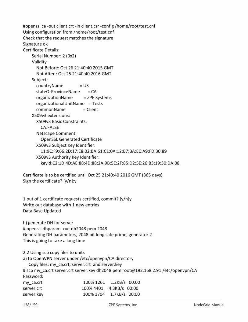
138/159 ZPE Systems, Inc. NodeGrid Manual
#openssl ca -out client.crt -in client.csr -config /home/root/test.cnf Using configuration from /home/root/test.cnf Check that the request matches the signature Signature ok Certificate Details: Serial Number: 2 (0x2) Validity Not Before: Oct 26 21:40:40 2015 GMT Not After : Oct 25 21:40:40 2016 GMT Subject: countryName = US stateOrProvinceName = CA organizationName = ZPE Systems organizationalUnitName = Tests commonName = Client X509v3 extensions: X509v3 Basic Constraints: CA:FALSE Netscape Comment: OpenSSL Generated Certificate X509v3 Subject Key Identifier: 11:9C:F9:66:2D:17:E8:02:BA:61:C1:0A:12:B7:BA:EC:A9:FD:30:89 X509v3 Authority Key Identifier: keyid:C2:1D:4D:AE:88:4D:88:2A:9B:5E:2F:85:D2:5E:26:B3:19:30:DA:08 Certificate is to be certified until Oct 25 21:40:40 2016 GMT (365 days) Sign the certificate? [y/n]:y 1 out of 1 certificate requests certified, commit? [y/n]y Write out database with 1 new entries Data Base Updated h) generate DH for server # openssl dhparam -out dh2048.pem 2048 Generating DH parameters, 2048 bit long safe prime, generator 2 This is going to take a long time 2.2 Using scp copy files to units a) to OpenVPN server under /etc/openvpn/CA directory Copy files: my_ca.crt, server.crt and server.key # scp my_ca.crt server.crt server.key dh2048.pem [email protected]:/etc/openvpn/CA Password: my_ca.crt 100% 1261 1.2KB/s 00:00 server.crt 100% 4401 4.3KB/s 00:00 server.key 100% 1704 1.7KB/s 00:00
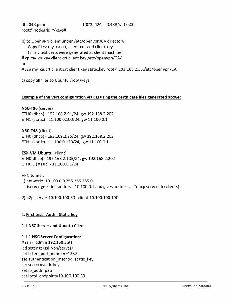
139/159 ZPE Systems, Inc. NodeGrid Manual
dh2048.pem 100% 424 0.4KB/s 00:00 root@nodegrid:~/keys# b) to OpenVPN client under /etc/openvpn/CA directory Copy files: my_ca.crt, client.crt and client.key (in my test certs were generated at client machine) # cp my_ca.key client.crt client.key /etc/openvpn/CA/ or # scp my_ca.crt client.crt client.key static.key [email protected]:/etc/openvpn/CA c) copy all files to Ubuntu /root/keys Example of the VPN configuration via CLI using the certificate files generated above: NSC-T96 (server) ETH0 (dhcp) - 192.168.2.91/24, gw 192.168.2.202 ETH1 (static) - 11.100.0.100/24. gw 11.100.0.1 NSC-T48 (client) ETH0 (dhcp) - 192.169.2.35/24, gw 192.168.2.202 ETH1 (static) - 11.100.0.120/24, gw 11.100.0.1 ESX-VM-Ubuntu (client) ETH0(dhcp) - 192.168.2.103/24, gw 192.168.2.202 ETH0:1 (static) - 11.100.0.1/24 VPN tunnel: 1) network: 10.100.0.0 255.255.255.0 (server gets first address: 10.100.0.1 and gives address as "dhcp server" to clients) 2) p2p: server 10.100.100.50 client 10.100.100.100 1. First test - Auth - Static-key 1.1 NSC Server and Ubuntu Client 1.1.1 NSC Server Configuration: # ssh -l admin 192.168.2.91 cd settings/ssl_vpn/server/ set listen_port_number=1357 set authentication_method=static_key set secret=static.key set ip_addr=p2p set local_endpoint=10.100.100.50
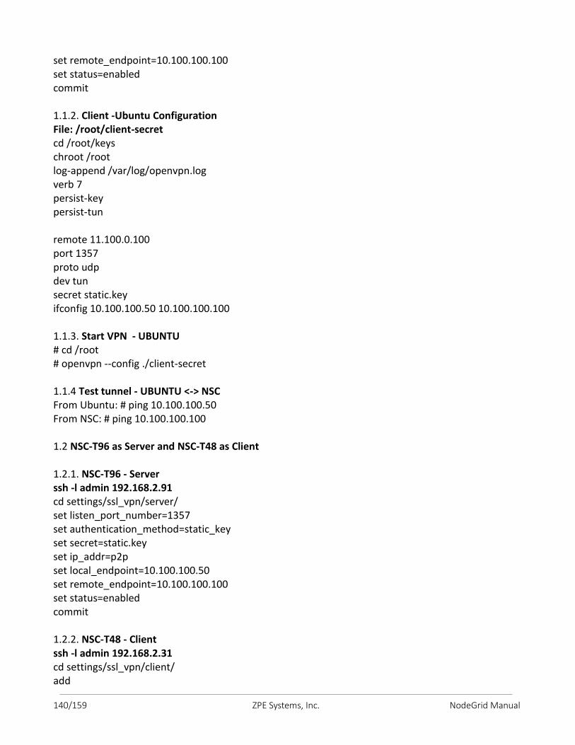
140/159 ZPE Systems, Inc. NodeGrid Manual
set remote_endpoint=10.100.100.100 set status=enabled commit 1.1.2. Client -Ubuntu Configuration File: /root/client-secret cd /root/keys chroot /root log-append /var/log/openvpn.log verb 7 persist-key persist-tun remote 11.100.0.100 port 1357 proto udp dev tun secret static.key ifconfig 10.100.100.50 10.100.100.100 1.1.3. Start VPN - UBUNTU # cd /root # openvpn --config ./client-secret 1.1.4 Test tunnel - UBUNTU <-> NSC From Ubuntu: # ping 10.100.100.50 From NSC: # ping 10.100.100.100 1.2 NSC-T96 as Server and NSC-T48 as Client 1.2.1. NSC-T96 - Server ssh -l admin 192.168.2.91 cd settings/ssl_vpn/server/ set listen_port_number=1357 set authentication_method=static_key set secret=static.key set ip_addr=p2p set local_endpoint=10.100.100.50 set remote_endpoint=10.100.100.100 set status=enabled commit 1.2.2. NSC-T48 - Client ssh -l admin 192.168.2.31 cd settings/ssl_vpn/client/ add
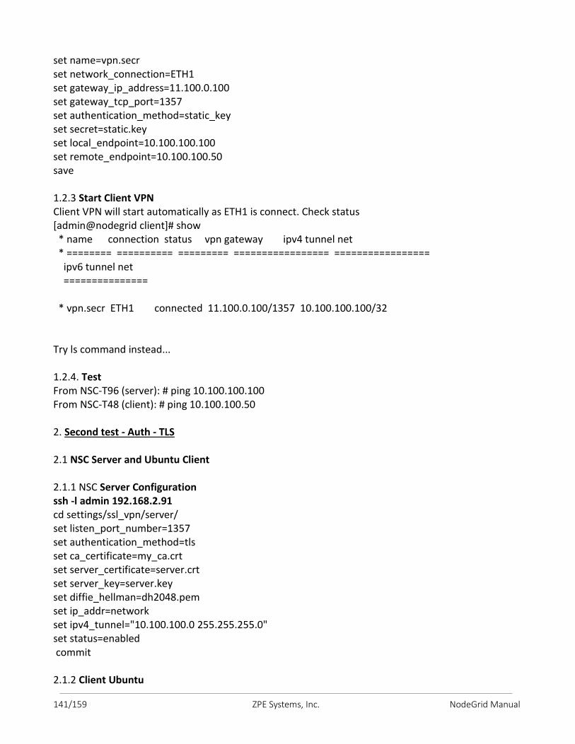
141/159 ZPE Systems, Inc. NodeGrid Manual
set name=vpn.secr set network_connection=ETH1 set gateway_ip_address=11.100.0.100 set gateway_tcp_port=1357 set authentication_method=static_key set secret=static.key set local_endpoint=10.100.100.100 set remote_endpoint=10.100.100.50 save 1.2.3 Start Client VPN Client VPN will start automatically as ETH1 is connect. Check status [admin@nodegrid client]# show * name connection status vpn gateway ipv4 tunnel net * ======== ========== ========= ================= ================= ipv6 tunnel net =============== * vpn.secr ETH1 connected 11.100.0.100/1357 10.100.100.100/32 Try ls command instead... 1.2.4. Test From NSC-T96 (server): # ping 10.100.100.100 From NSC-T48 (client): # ping 10.100.100.50 2. Second test - Auth - TLS 2.1 NSC Server and Ubuntu Client 2.1.1 NSC Server Configuration ssh -l admin 192.168.2.91 cd settings/ssl_vpn/server/ set listen_port_number=1357 set authentication_method=tls set ca_certificate=my_ca.crt set server_certificate=server.crt set server_key=server.key set diffie_hellman=dh2048.pem set ip_addr=network set ipv4_tunnel="10.100.100.0 255.255.255.0" set status=enabled commit 2.1.2 Client Ubuntu
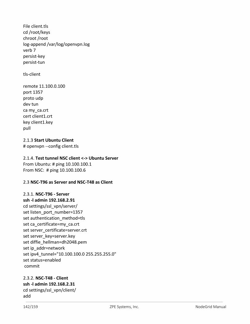
142/159 ZPE Systems, Inc. NodeGrid Manual
File client.tls cd /root/keys chroot /root log-append /var/log/openvpn.log verb 7 persist-key persist-tun tls-client remote 11.100.0.100 port 1357 proto udp dev tun ca my_ca.crt cert client1.crt key client1.key pull 2.1.3 Start Ubuntu Client # openvpn --config client.tls 2.1.4. Test tunnel NSC client <-> Ubuntu Server From Ubuntu: # ping 10.100.100.1 From NSC: # ping 10.100.100.6 2.3 NSC-T96 as Server and NSC-T48 as Client 2.3.1. NSC-T96 - Server ssh -l admin 192.168.2.91 cd settings/ssl_vpn/server/ set listen_port_number=1357 set authentication_method=tls set ca_certificate=my_ca.crt set server_certificate=server.crt set server_key=server.key set diffie_hellman=dh2048.pem set ip_addr=network set ipv4_tunnel="10.100.100.0 255.255.255.0" set status=enabled commit 2.3.2. NSC-T48 - Client ssh -l admin 192.168.2.31 cd settings/ssl_vpn/client/ add
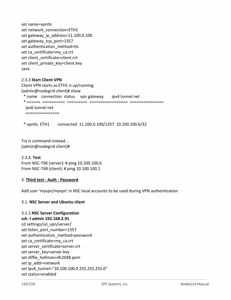
143/159 ZPE Systems, Inc. NodeGrid Manual
set name=vpntls set network_connection=ETH1 set gateway_ip_address=11.100.0.100 set gateway_tcp_port=1357 set authentication_method=tls set ca_certificate=my_ca.crt set client_certificate=client.crt set client_private_key=client.key save 2.3.3 Start Client VPN Client VPN starts as ETH1 is up/running. [admin@nodegrid client]# show * name connection status vpn gateway ipv4 tunnel net * ====== ========== ========= ================= =============== ipv6 tunnel net =============== * vpntls ETH1 connected 11.100.0.100/1357 10.100.100.6/32 Try ls command instead... [admin@nodegrid client]# 2.3.4. Test From NSC-T96 (server): # ping 10.100.100.6 From NSC-T48 (client): # ping 10.100.100.1 3. Third test - Auth - Password Add user 'myvpn/myvpn' in NSC local accounts to be used during VPN authentication 3.1. NSC Server and Ubuntu client 3.1.1 NSC Server Configuration ssh -l admin 192.168.2.91 cd settings/ssl_vpn/server/ set listen_port_number=1357 set authentication_method=password set ca_certificate=my_ca.crt set server_certificate=server.crt set server_key=server.key set diffie_hellman=dh2048.pem set ip_addr=network set ipv4_tunnel="10.100.100.0 255.255.255.0" set status=enabled
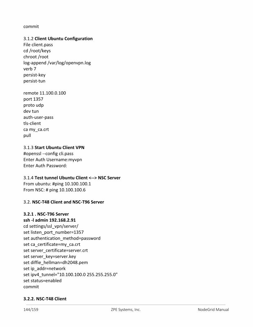
144/159 ZPE Systems, Inc. NodeGrid Manual
commit 3.1.2 Client Ubuntu Configuration File client.pass cd /root/keys chroot /root log-append /var/log/openvpn.log verb 7 persist-key persist-tun remote 11.100.0.100 port 1357 proto udp dev tun auth-user-pass tls-client ca my_ca.crt pull 3.1.3 Start Ubuntu Client VPN #openssl --config cli.pass Enter Auth Username:myvpn Enter Auth Password: 3.1.4 Test tunnel Ubuntu Client <--> NSC Server From ubuntu: #ping 10.100.100.1 From NSC: # ping 10.100.100.6 3.2. NSC-T48 Client and NSC-T96 Server 3.2.1 . NSC-T96 Server ssh -l admin 192.168.2.91 cd settings/ssl_vpn/server/ set listen_port_number=1357 set authentication_method=password set ca_certificate=my_ca.crt set server_certificate=server.crt set server_key=server.key set diffie_hellman=dh2048.pem set ip_addr=network set ipv4_tunnel="10.100.100.0 255.255.255.0" set status=enabled commit 3.2.2. NSC-T48 Client
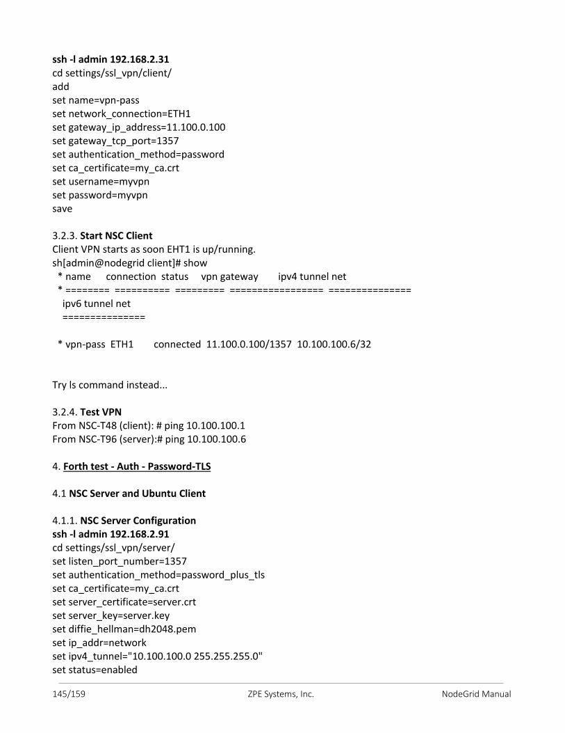
145/159 ZPE Systems, Inc. NodeGrid Manual
ssh -l admin 192.168.2.31 cd settings/ssl_vpn/client/ add set name=vpn-pass set network_connection=ETH1 set gateway_ip_address=11.100.0.100 set gateway_tcp_port=1357 set authentication_method=password set ca_certificate=my_ca.crt set username=myvpn set password=myvpn save 3.2.3. Start NSC Client Client VPN starts as soon EHT1 is up/running. sh[admin@nodegrid client]# show * name connection status vpn gateway ipv4 tunnel net * ======== ========== ========= ================= =============== ipv6 tunnel net =============== * vpn-pass ETH1 connected 11.100.0.100/1357 10.100.100.6/32 Try ls command instead... 3.2.4. Test VPN From NSC-T48 (client): # ping 10.100.100.1 From NSC-T96 (server):# ping 10.100.100.6 4. Forth test - Auth - Password-TLS 4.1 NSC Server and Ubuntu Client 4.1.1. NSC Server Configuration ssh -l admin 192.168.2.91 cd settings/ssl_vpn/server/ set listen_port_number=1357 set authentication_method=password_plus_tls set ca_certificate=my_ca.crt set server_certificate=server.crt set server_key=server.key set diffie_hellman=dh2048.pem set ip_addr=network set ipv4_tunnel="10.100.100.0 255.255.255.0" set status=enabled
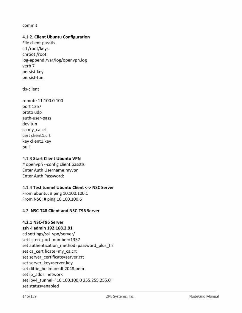
146/159 ZPE Systems, Inc. NodeGrid Manual
commit 4.1.2. Client Ubuntu Configuration File client.passtls cd /root/keys chroot /root log-append /var/log/openvpn.log verb 7 persist-key persist-tun tls-client remote 11.100.0.100 port 1357 proto udp auth-user-pass dev tun ca my_ca.crt cert client1.crt key client1.key pull 4.1.3 Start Client Ubuntu VPN # openvpn --config client.passtls Enter Auth Username:myvpn Enter Auth Password: 4.1.4 Test tunnel Ubuntu Client <-> NSC Server From ubuntu: # ping 10.100.100.1 From NSC: # ping 10.100.100.6 4.2. NSC-T48 Client and NSC-T96 Server 4.2.1 NSC-T96 Server ssh -l admin 192.168.2.91 cd settings/ssl_vpn/server/ set listen_port_number=1357 set authentication_method=password_plus_tls set ca_certificate=my_ca.crt set server_certificate=server.crt set server_key=server.key set diffie_hellman=dh2048.pem set ip_addr=network set ipv4_tunnel="10.100.100.0 255.255.255.0" set status=enabled
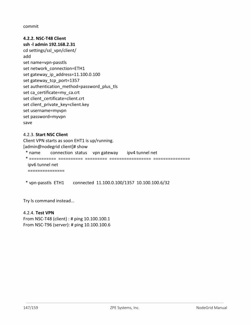
147/159 ZPE Systems, Inc. NodeGrid Manual
commit 4.2.2. NSC-T48 Client ssh -l admin 192.168.2.31 cd settings/ssl_vpn/client/ add set name=vpn-passtls set network_connection=ETH1 set gateway_ip_address=11.100.0.100 set gateway_tcp_port=1357 set authentication_method=password_plus_tls set ca_certificate=my_ca.crt set client_certificate=client.crt set client_private_key=client.key set username=myvpn set password=myvpn save 4.2.3. Start NSC Client Client VPN starts as soon EHT1 is up/running. [admin@nodegrid client]# show * name connection status vpn gateway ipv4 tunnel net * =========== ========== ========= ================= =============== ipv6 tunnel net =============== * vpn-passtls ETH1 connected 11.100.0.100/1357 10.100.100.6/32 Try ls command instead... 4.2.4. Test VPN From NSC-T48 (client) : # ping 10.100.100.1 From NSC-T96 (server): # ping 10.100.100.6
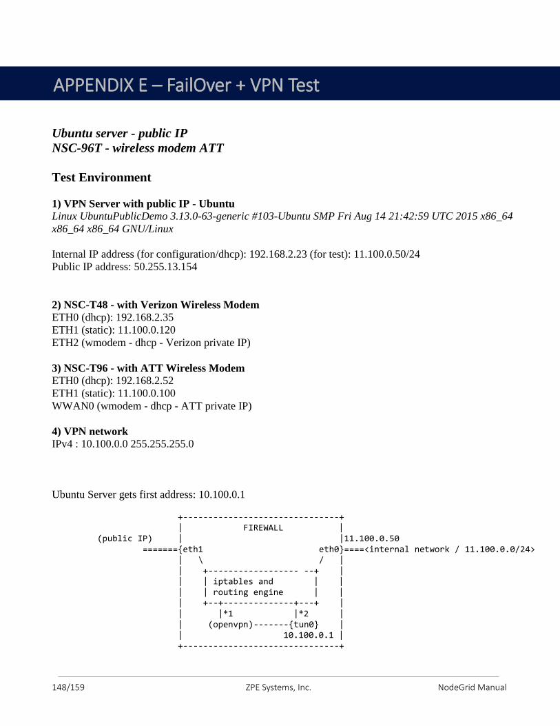
148/159 ZPE Systems, Inc. NodeGrid Manual
Ubuntu server - public IP
NSC-96T - wireless modem ATT
Test Environment
1) VPN Server with public IP - Ubuntu
Linux UbuntuPublicDemo 3.13.0-63-generic #103-Ubuntu SMP Fri Aug 14 21:42:59 UTC 2015 x86_64
x86_64 x86_64 GNU/Linux
Internal IP address (for configuration/dhcp): 192.168.2.23 (for test): 11.100.0.50/24
Public IP address: 50.255.13.154
2) NSC-T48 - with Verizon Wireless Modem ETH0 (dhcp): 192.168.2.35
ETH1 (static): 11.100.0.120
ETH2 (wmodem - dhcp - Verizon private IP)
3) NSC-T96 - with ATT Wireless Modem
ETH0 (dhcp): 192.168.2.52
ETH1 (static): 11.100.0.100
WWAN0 (wmodem - dhcp - ATT private IP)
4) VPN network
IPv4 : 10.100.0.0 255.255.255.0
Ubuntu Server gets first address: 10.100.0.1 +-------------------------------+ | FIREWALL | (public IP) | |11.100.0.50 ======={eth1 eth0}====<internal network / 11.100.0.0/24> | \ / | | +------------------ --+ | | | iptables and | | | | routing engine | | | +--+--------------+---+ | | |*1 |*2 | | (openvpn)-------{tun0} | | 10.100.0.1 | +-------------------------------+
APPENDIX E – FailOver + VPN Test
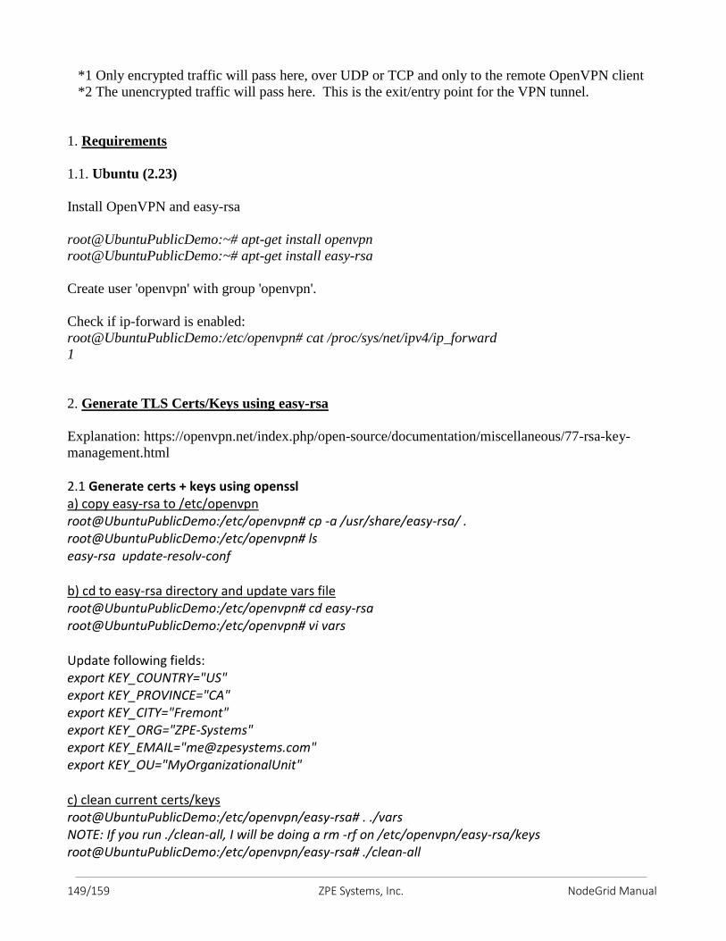
149/159 ZPE Systems, Inc. NodeGrid Manual
*1 Only encrypted traffic will pass here, over UDP or TCP and only to the remote OpenVPN client
*2 The unencrypted traffic will pass here. This is the exit/entry point for the VPN tunnel.
1. Requirements
1.1. Ubuntu (2.23)
Install OpenVPN and easy-rsa
root@UbuntuPublicDemo:~# apt-get install openvpn
root@UbuntuPublicDemo:~# apt-get install easy-rsa
Create user 'openvpn' with group 'openvpn'.
Check if ip-forward is enabled:
root@UbuntuPublicDemo:/etc/openvpn# cat /proc/sys/net/ipv4/ip_forward
1
2. Generate TLS Certs/Keys using easy-rsa
Explanation: https://openvpn.net/index.php/open-source/documentation/miscellaneous/77-rsa-key-
management.html
2.1 Generate certs + keys using openssl a) copy easy-rsa to /etc/openvpn root@UbuntuPublicDemo:/etc/openvpn# cp -a /usr/share/easy-rsa/ . root@UbuntuPublicDemo:/etc/openvpn# ls easy-rsa update-resolv-conf b) cd to easy-rsa directory and update vars file root@UbuntuPublicDemo:/etc/openvpn# cd easy-rsa root@UbuntuPublicDemo:/etc/openvpn# vi vars Update following fields: export KEY_COUNTRY="US" export KEY_PROVINCE="CA" export KEY_CITY="Fremont" export KEY_ORG="ZPE-Systems" export KEY_EMAIL="[email protected]" export KEY_OU="MyOrganizationalUnit" c) clean current certs/keys root@UbuntuPublicDemo:/etc/openvpn/easy-rsa# . ./vars NOTE: If you run ./clean-all, I will be doing a rm -rf on /etc/openvpn/easy-rsa/keys root@UbuntuPublicDemo:/etc/openvpn/easy-rsa# ./clean-all

150/159 ZPE Systems, Inc. NodeGrid Manual
d) generate CA cert/key root@UbuntuPublicDemo:/etc/openvpn/easy-rsa# ./build-ca Generating a 2048 bit RSA private key ................................................................................+++ ..............................+++ writing new private key to 'ca.key' ----- You are about to be asked to enter information that will be incorporated into your certificate request. What you are about to enter is what is called a Distinguished Name or a DN. There are quite a few fields but you can leave some blank For some fields there will be a default value, If you enter '.', the field will be left blank. ----- Country Name (2 letter code) [US]: State or Province Name (full name) [CA]: Locality Name (eg, city) [Fremont]: Organization Name (eg, company) [ZPE-Systems]: Organizational Unit Name (eg, section) [MyOrganizationalUnit]: Common Name (eg, your name or your server's hostname) [ZPE-Systems CA]: Name [EasyRSA]: Email Address [[email protected]]: root@UbuntuPublicDemo:/etc/openvpn/easy-rsa# e) create Ubuntu-Server cert/key - and sign it root@UbuntuPublicDemo:/etc/openvpn/easy-rsa# ./build-key-server Ubuntu-Server Generating a 2048 bit RSA private key ...+++ ......................................................................+++ writing new private key to 'Ubuntu-Server.key' ----- You are about to be asked to enter information that will be incorporated into your certificate request. What you are about to enter is what is called a Distinguished Name or a DN. There are quite a few fields but you can leave some blank For some fields there will be a default value, If you enter '.', the field will be left blank. ----- Country Name (2 letter code) [US]: State or Province Name (full name) [CA]: Locality Name (eg, city) [Fremont]: Organization Name (eg, company) [ZPE-Systems]: Organizational Unit Name (eg, section) [MyOrganizationalUnit]: Common Name (eg, your name or your server's hostname) [Ubuntu-Server]: Name [EasyRSA]: Email Address [[email protected]]:
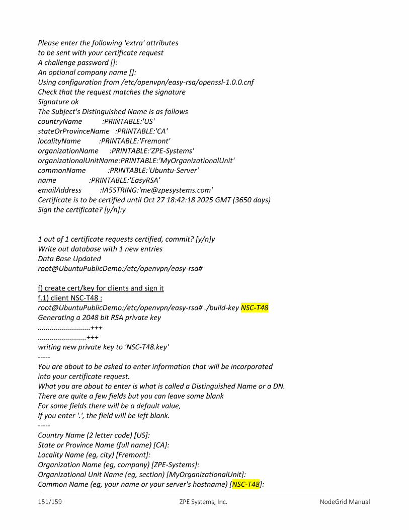
151/159 ZPE Systems, Inc. NodeGrid Manual
Please enter the following 'extra' attributes to be sent with your certificate request A challenge password []: An optional company name []: Using configuration from /etc/openvpn/easy-rsa/openssl-1.0.0.cnf Check that the request matches the signature Signature ok The Subject's Distinguished Name is as follows countryName :PRINTABLE:'US' stateOrProvinceName :PRINTABLE:'CA' localityName :PRINTABLE:'Fremont' organizationName :PRINTABLE:'ZPE-Systems' organizationalUnitName:PRINTABLE:'MyOrganizationalUnit' commonName :PRINTABLE:'Ubuntu-Server' name :PRINTABLE:'EasyRSA' emailAddress :IA5STRING:'[email protected]' Certificate is to be certified until Oct 27 18:42:18 2025 GMT (3650 days) Sign the certificate? [y/n]:y 1 out of 1 certificate requests certified, commit? [y/n]y Write out database with 1 new entries Data Base Updated root@UbuntuPublicDemo:/etc/openvpn/easy-rsa# f) create cert/key for clients and sign it f.1) client NSC-T48 : root@UbuntuPublicDemo:/etc/openvpn/easy-rsa# ./build-key NSC-T48 Generating a 2048 bit RSA private key ..........................+++ ........................+++ writing new private key to 'NSC-T48.key' ----- You are about to be asked to enter information that will be incorporated into your certificate request. What you are about to enter is what is called a Distinguished Name or a DN. There are quite a few fields but you can leave some blank For some fields there will be a default value, If you enter '.', the field will be left blank. ----- Country Name (2 letter code) [US]: State or Province Name (full name) [CA]: Locality Name (eg, city) [Fremont]: Organization Name (eg, company) [ZPE-Systems]: Organizational Unit Name (eg, section) [MyOrganizationalUnit]: Common Name (eg, your name or your server's hostname) [NSC-T48]:
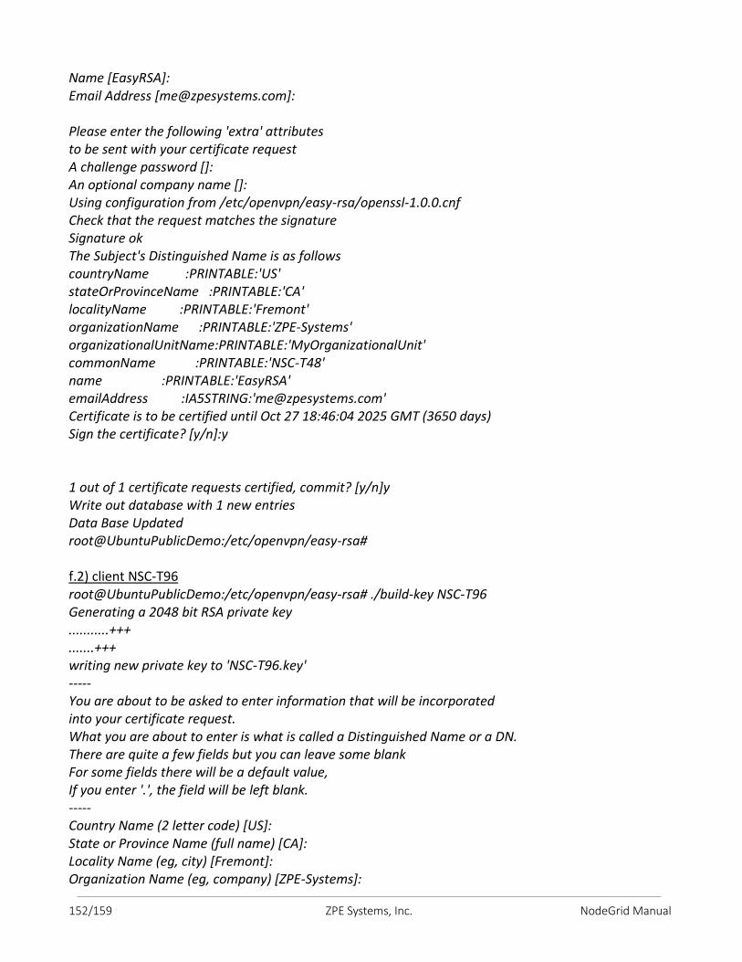
152/159 ZPE Systems, Inc. NodeGrid Manual
Name [EasyRSA]: Email Address [[email protected]]: Please enter the following 'extra' attributes to be sent with your certificate request A challenge password []: An optional company name []: Using configuration from /etc/openvpn/easy-rsa/openssl-1.0.0.cnf Check that the request matches the signature Signature ok The Subject's Distinguished Name is as follows countryName :PRINTABLE:'US' stateOrProvinceName :PRINTABLE:'CA' localityName :PRINTABLE:'Fremont' organizationName :PRINTABLE:'ZPE-Systems' organizationalUnitName:PRINTABLE:'MyOrganizationalUnit' commonName :PRINTABLE:'NSC-T48' name :PRINTABLE:'EasyRSA' emailAddress :IA5STRING:'[email protected]' Certificate is to be certified until Oct 27 18:46:04 2025 GMT (3650 days) Sign the certificate? [y/n]:y 1 out of 1 certificate requests certified, commit? [y/n]y Write out database with 1 new entries Data Base Updated root@UbuntuPublicDemo:/etc/openvpn/easy-rsa# f.2) client NSC-T96 root@UbuntuPublicDemo:/etc/openvpn/easy-rsa# ./build-key NSC-T96 Generating a 2048 bit RSA private key ...........+++ .......+++ writing new private key to 'NSC-T96.key' ----- You are about to be asked to enter information that will be incorporated into your certificate request. What you are about to enter is what is called a Distinguished Name or a DN. There are quite a few fields but you can leave some blank For some fields there will be a default value, If you enter '.', the field will be left blank. ----- Country Name (2 letter code) [US]: State or Province Name (full name) [CA]: Locality Name (eg, city) [Fremont]: Organization Name (eg, company) [ZPE-Systems]:
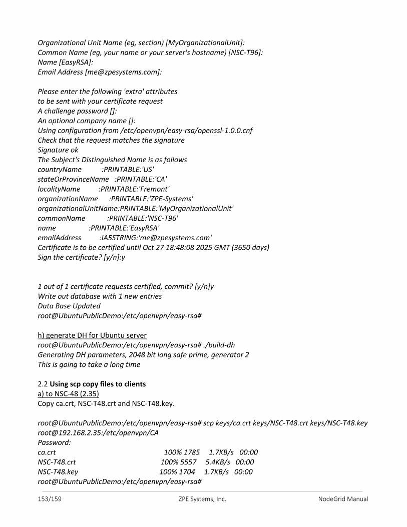
153/159 ZPE Systems, Inc. NodeGrid Manual
Organizational Unit Name (eg, section) [MyOrganizationalUnit]: Common Name (eg, your name or your server's hostname) [NSC-T96]: Name [EasyRSA]: Email Address [[email protected]]: Please enter the following 'extra' attributes to be sent with your certificate request A challenge password []: An optional company name []: Using configuration from /etc/openvpn/easy-rsa/openssl-1.0.0.cnf Check that the request matches the signature Signature ok The Subject's Distinguished Name is as follows countryName :PRINTABLE:'US' stateOrProvinceName :PRINTABLE:'CA' localityName :PRINTABLE:'Fremont' organizationName :PRINTABLE:'ZPE-Systems' organizationalUnitName:PRINTABLE:'MyOrganizationalUnit' commonName :PRINTABLE:'NSC-T96' name :PRINTABLE:'EasyRSA' emailAddress :IA5STRING:'[email protected]' Certificate is to be certified until Oct 27 18:48:08 2025 GMT (3650 days) Sign the certificate? [y/n]:y 1 out of 1 certificate requests certified, commit? [y/n]y Write out database with 1 new entries Data Base Updated root@UbuntuPublicDemo:/etc/openvpn/easy-rsa# h) generate DH for Ubuntu server root@UbuntuPublicDemo:/etc/openvpn/easy-rsa# ./build-dh Generating DH parameters, 2048 bit long safe prime, generator 2 This is going to take a long time 2.2 Using scp copy files to clients a) to NSC-48 (2.35) Copy ca.crt, NSC-T48.crt and NSC-T48.key. root@UbuntuPublicDemo:/etc/openvpn/easy-rsa# scp keys/ca.crt keys/NSC-T48.crt keys/NSC-T48.key [email protected]:/etc/openvpn/CA Password: ca.crt 100% 1785 1.7KB/s 00:00 NSC-T48.crt 100% 5557 5.4KB/s 00:00 NSC-T48.key 100% 1704 1.7KB/s 00:00 root@UbuntuPublicDemo:/etc/openvpn/easy-rsa#
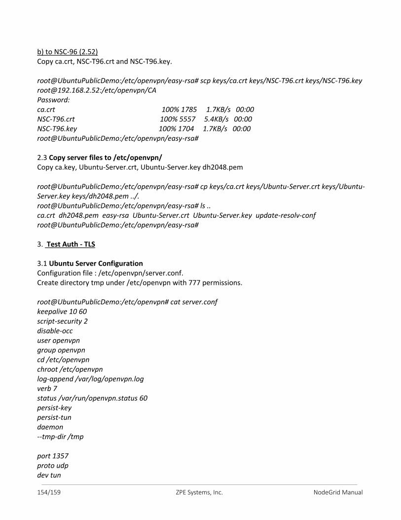
154/159 ZPE Systems, Inc. NodeGrid Manual
b) to NSC-96 (2.52) Copy ca.crt, NSC-T96.crt and NSC-T96.key. root@UbuntuPublicDemo:/etc/openvpn/easy-rsa# scp keys/ca.crt keys/NSC-T96.crt keys/NSC-T96.key [email protected]:/etc/openvpn/CA Password: ca.crt 100% 1785 1.7KB/s 00:00 NSC-T96.crt 100% 5557 5.4KB/s 00:00 NSC-T96.key 100% 1704 1.7KB/s 00:00 root@UbuntuPublicDemo:/etc/openvpn/easy-rsa# 2.3 Copy server files to /etc/openvpn/ Copy ca.key, Ubuntu-Server.crt, Ubuntu-Server.key dh2048.pem root@UbuntuPublicDemo:/etc/openvpn/easy-rsa# cp keys/ca.crt keys/Ubuntu-Server.crt keys/Ubuntu-Server.key keys/dh2048.pem ../. root@UbuntuPublicDemo:/etc/openvpn/easy-rsa# ls .. ca.crt dh2048.pem easy-rsa Ubuntu-Server.crt Ubuntu-Server.key update-resolv-conf root@UbuntuPublicDemo:/etc/openvpn/easy-rsa# 3. Test Auth - TLS 3.1 Ubuntu Server Configuration Configuration file : /etc/openvpn/server.conf. Create directory tmp under /etc/openvpn with 777 permissions. root@UbuntuPublicDemo:/etc/openvpn# cat server.conf keepalive 10 60 script-security 2 disable-occ user openvpn group openvpn cd /etc/openvpn chroot /etc/openvpn log-append /var/log/openvpn.log verb 7 status /var/run/openvpn.status 60 persist-key persist-tun daemon --tmp-dir /tmp port 1357 proto udp dev tun
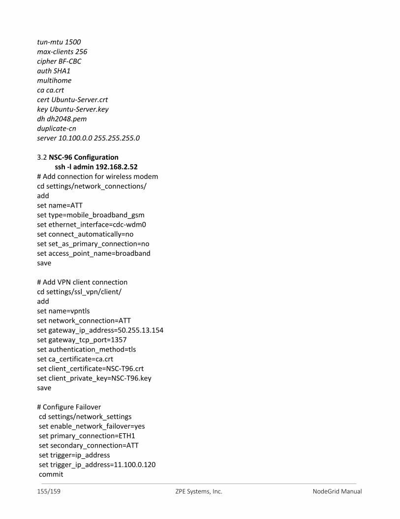
155/159 ZPE Systems, Inc. NodeGrid Manual
tun-mtu 1500 max-clients 256 cipher BF-CBC auth SHA1 multihome ca ca.crt cert Ubuntu-Server.crt key Ubuntu-Server.key dh dh2048.pem duplicate-cn server 10.100.0.0 255.255.255.0 3.2 NSC-96 Configuration ssh -l admin 192.168.2.52 # Add connection for wireless modem cd settings/network_connections/ add set name=ATT set type=mobile_broadband_gsm set ethernet_interface=cdc-wdm0 set connect_automatically=no set set_as_primary_connection=no set access_point_name=broadband save # Add VPN client connection cd settings/ssl_vpn/client/ add set name=vpntls set network_connection=ATT set gateway_ip_address=50.255.13.154 set gateway_tcp_port=1357 set authentication_method=tls set ca_certificate=ca.crt set client_certificate=NSC-T96.crt set client_private_key=NSC-T96.key save # Configure Failover cd settings/network_settings set enable_network_failover=yes set primary_connection=ETH1 set secondary_connection=ATT set trigger=ip_address set trigger_ip_address=11.100.0.120 commit
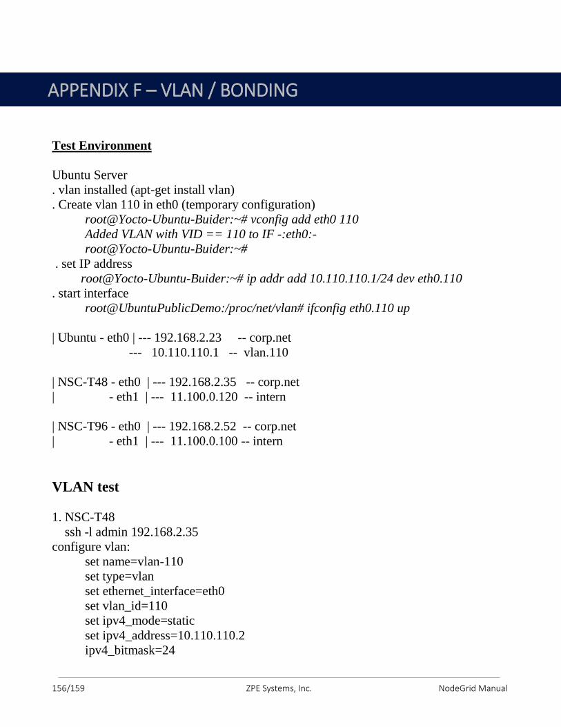
156/159 ZPE Systems, Inc. NodeGrid Manual
Test Environment
Ubuntu Server
. vlan installed (apt-get install vlan)
. Create vlan 110 in eth0 (temporary configuration)
root@Yocto-Ubuntu-Buider:~# vconfig add eth0 110
Added VLAN with VID == 110 to IF -:eth0:-
root@Yocto-Ubuntu-Buider:~#
. set IP address
root@Yocto-Ubuntu-Buider:~# ip addr add 10.110.110.1/24 dev eth0.110
. start interface
root@UbuntuPublicDemo:/proc/net/vlan# ifconfig eth0.110 up
| Ubuntu - eth0 | --- 192.168.2.23 -- corp.net
--- 10.110.110.1 -- vlan.110
| NSC-T48 - eth0 | --- 192.168.2.35 -- corp.net
| - eth1 | --- 11.100.0.120 -- intern
| NSC-T96 - eth0 | --- 192.168.2.52 -- corp.net
| - eth1 | --- 11.100.0.100 -- intern
VLAN test
1. NSC-T48
ssh -l admin 192.168.2.35
configure vlan:
set name=vlan-110
set type=vlan
set ethernet_interface=eth0
set vlan_id=110
set ipv4_mode=static
set ipv4_address=10.110.110.2
ipv4_bitmask=24
APPENDIX F – VLAN / BONDING
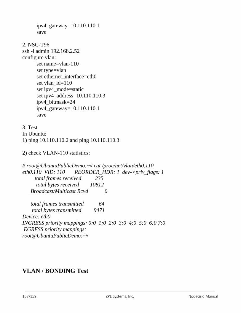
157/159 ZPE Systems, Inc. NodeGrid Manual
ipv4_gateway=10.110.110.1
save
2. NSC-T96
ssh -l admin 192.168.2.52
configure vlan:
set name=vlan-110
set type=vlan
set ethernet_interface=eth0
set vlan_id=110
set ipv4_mode=static
set ipv4_address=10.110.110.3
ipv4_bitmask=24
ipv4_gateway=10.110.110.1
save
3. Test
In Ubuntu:
1) ping 10.110.110.2 and ping 10.110.110.3
2) check VLAN-110 statistics:
# root@UbuntuPublicDemo:~# cat /proc/net/vlan/eth0.110
eth0.110 VID: 110 REORDER_HDR: 1 dev->priv_flags: 1
total frames received 235
total bytes received 10812
Broadcast/Multicast Rcvd 0
total frames transmitted 64
total bytes transmitted 9471
Device: eth0
INGRESS priority mappings: 0:0 1:0 2:0 3:0 4:0 5:0 6:0 7:0
EGRESS priority mappings:
root@UbuntuPublicDemo:~#
VLAN / BONDING Test
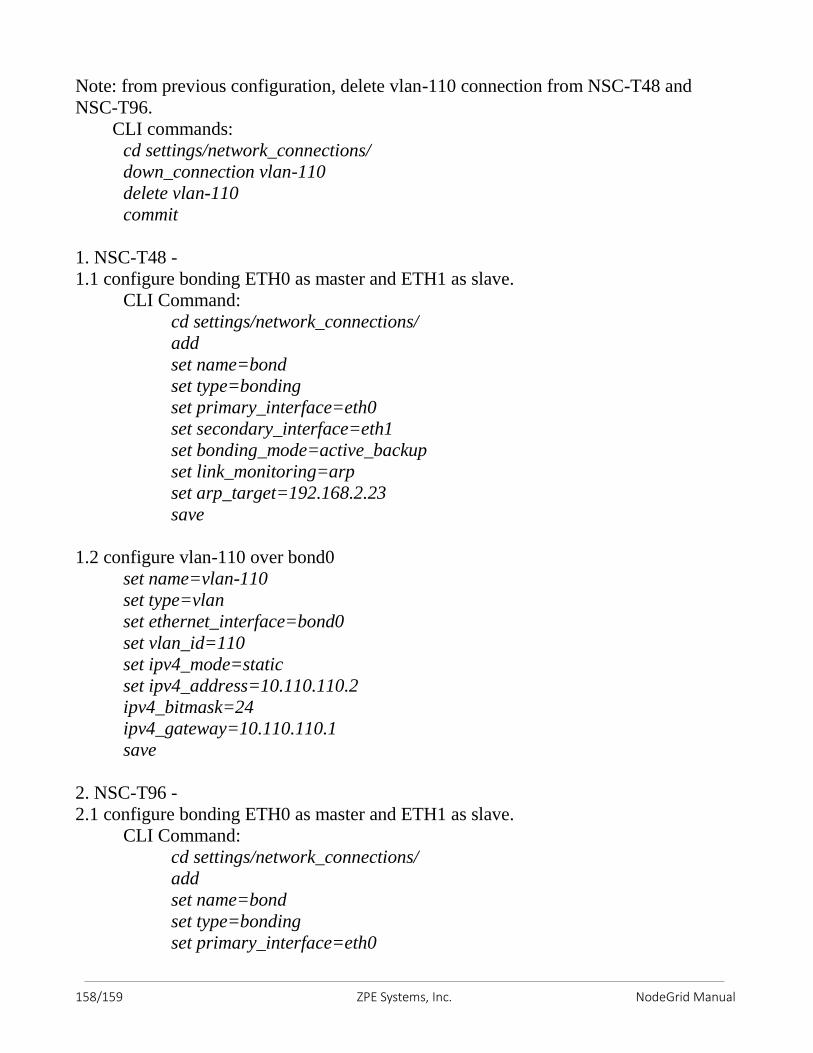
158/159 ZPE Systems, Inc. NodeGrid Manual
Note: from previous configuration, delete vlan-110 connection from NSC-T48 and
NSC-T96.
CLI commands:
cd settings/network_connections/
down_connection vlan-110
delete vlan-110
commit
1. NSC-T48 -
1.1 configure bonding ETH0 as master and ETH1 as slave.
CLI Command:
cd settings/network_connections/
add
set name=bond
set type=bonding
set primary_interface=eth0
set secondary_interface=eth1
set bonding_mode=active_backup
set link_monitoring=arp
set arp_target=192.168.2.23
save
1.2 configure vlan-110 over bond0
set name=vlan-110
set type=vlan
set ethernet_interface=bond0
set vlan_id=110
set ipv4_mode=static
set ipv4_address=10.110.110.2
ipv4_bitmask=24
ipv4_gateway=10.110.110.1
save
2. NSC-T96 -
2.1 configure bonding ETH0 as master and ETH1 as slave.
CLI Command:
cd settings/network_connections/
add
set name=bond
set type=bonding
set primary_interface=eth0
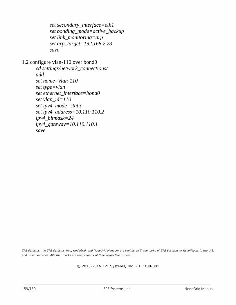
159/159 ZPE Systems, Inc. NodeGrid Manual
set secondary_interface=eth1
set bonding_mode=active_backup
set link_monitoring=arp
set arp_target=192.168.2.23
save
1.2 configure vlan-110 over bond0
cd settings/network_connections/
add
set name=vlan-110
set type=vlan
set ethernet_interface=bond0
set vlan_id=110
set ipv4_mode=static
set ipv4_address=10.110.110.2
ipv4_bitmask=24
ipv4_gateway=10.110.110.1
save
ZPE Systems, the ZPE Systems logo, NodeGrid, and NodeGrid Manager are registered Trademarks of ZPE Systems or its affiliates in the U.S.
and other countries. All other marks are the property of their respective owners.
© 2013-2016 ZPE Systems, Inc. – DO100-001


![Introduction à la méthode des éléments finismedias.dunod.com/document/9782100742622/Feuilletage.pdf · 9.4.1 Introduction 198 9.4.2 Calcul de la matrice [H] 199 ... conséquent,](https://img.pdfslide.us/doc/110x75/5b95ccc209d3f2de4a8c792d/introduction-a-la-methode-des-elements-941-introduction-198-942-calcul.jpg)