Embed Size (px)
Citation preview
A guide to Martin Audio’s VU-NET Control and Monitoring Software for Multicellular and U-Net enabled Loudspeaker Systems
V4.5
User Guide
DD12

Vu‐Net USER GUIDE
Vu‐Net2.0 User Guide v4.5 2
…………
Contents Version History ................................................................................................................................................................................. 5
Installation .................................................................................................................................................................................... 5
System requirements ................................................................................................................................................................... 5
Vu‐Net .............................................................................................................................................................................................. 6
Introduction .................................................................................................................................................................................. 6
Menus ........................................................................................................................................................................................... 6
Window components ................................................................................................................................................................... 7
Menu and Toolbar .................................................................................................................................................................... 7
File ............................................................................................................................................................................................ 8
Edit ........................................................................................................................................................................................... 8
Preferences .............................................................................................................................................................................. 9
Tools ....................................................................................................................................................................................... 13
Window .................................................................................................................................................................................. 13
Help ........................................................................................................................................................................................ 13
Tool bar .................................................................................................................................................................................. 15
Project Workspace ................................................................................................................................................................. 18
Working Offline .......................................................................................................................................................................... 22
Adding Merlin, MLA, MLD and MLX ....................................................................................................................................... 22
Adding MLA Compact & DSX .................................................................................................................................................. 23
Adding MLA Mini .................................................................................................................................................................... 24
Adding DD12 .......................................................................................................................................................................... 27
Adding PSX ............................................................................................................................................................................. 27
Adding CDD Live ..................................................................................................................................................................... 27
Arranging the Array components ........................................................................................................................................... 28
Device Discovery ........................................................................................................................................................................ 33
Device Discovery MLA Mini ........................................................................................................................................................ 40
On line operation ................................................................................................................................................................... 51
Right‐Click menu .................................................................................................................................................................... 54
Renaming ............................................................................................................................................................................... 55
Presets & Snapshots ............................................................................................................................................................... 56
Loading Presets ...................................................................................................................................................................... 56
Defining Zones ........................................................................................................................................................................ 57
Synchronize ............................................................................................................................................................................ 59
Delete ..................................................................................................................................................................................... 59
MLA/MLD & Compact Arrays ..................................................................................................................................................... 59
Array Cell Check ..................................................................................................................................................................... 64
PEQ Tab .................................................................................................................................................................................. 70
Array & Zone Ganging ............................................................................................................................................................ 76

Vu‐Net USER GUIDE
Vu‐Net2.0 User Guide v4.5 3
…………
Array ganging ......................................................................................................................................................................... 77
MLX & DSX Arrays ....................................................................................................................................................................... 81
Block PEQ ............................................................................................................................................................................... 84
Sub Array/Block Ganging ........................................................................................................................................................ 85
MLA Mini .................................................................................................................................................................................... 87
MLA Mini Cell check ............................................................................................................................................................... 87
Assigning Zones in MLA Mini .................................................................................................................................................. 88
MLA Mini PEQ ........................................................................................................................................................................ 92
MLA Mini Ganging .................................................................................................................................................................. 93
DD12 ........................................................................................................................................................................................... 97
Overview .............................................................................................................................................................................. 102
EQ ......................................................................................................................................................................................... 106
Zones .................................................................................................................................................................................... 110
Noise Gate ............................................................................................................................................................................ 111
PSX ............................................................................................................................................................................................ 112
Overview .............................................................................................................................................................................. 117
EQ ......................................................................................................................................................................................... 122
Zones .................................................................................................................................................................................... 127
Noise Gate ............................................................................................................................................................................ 128
CDD Live ................................................................................................................................................................................... 129
Overview .............................................................................................................................................................................. 134
EQ ......................................................................................................................................................................................... 139
Zones .................................................................................................................................................................................... 143
Merlin ....................................................................................................................................................................................... 146
Gain, Mute & Limiters .......................................................................................................................................................... 146
Routing ................................................................................................................................................................................. 147
Input Channels ..................................................................................................................................................................... 149
Output Channels .................................................................................................................................................................. 152
Delay..................................................................................................................................................................................... 154
Delay Link ............................................................................................................................................................................. 156
Ganging ................................................................................................................................................................................ 158
Ganging entire Merlins ......................................................................................................................................................... 158
Input and output Ganging .................................................................................................................................................... 159
Individual parameter ganging .............................................................................................................................................. 160
Turning Ganging Off ............................................................................................................................................................. 160
Loading Presets ........................................................................................................................................................................ 162
PEQ files ............................................................................................................................................................................... 164
Other options ....................................................................................................................................................................... 165
Synchronise .......................................................................................................................................................................... 166

Vu‐Net USER GUIDE
Vu‐Net2.0 User Guide v4.5 4
…………
Master Overview ...................................................................................................................................................................... 168
Show Mode .............................................................................................................................................................................. 173
Firmware Updates .................................................................................................................................................................... 176
Get Firmware Updates ......................................................................................................................................................... 176
Starting a Firmware Update. ................................................................................................................................................ 178
MLA/MLD Conversion Tool .................................................................................................................................................. 182

Vu‐Net USER GUIDE
Vu‐Net2.0 User Guide v4.5 5
…………
Version History Manual Version 4.5;‐
Vu‐Net Version: 2.0.1.
Installation MLA and MLA Compact touring system owners will have a Tablet PC as part of their system package which will be pre‐loaded
with all necessary software including the latest version of Vu‐Net. For owners of Installed systems, MLA Mini, DD12, PSX or CDD
Live systems, Vu‐Net can be downloaded from the Martin Audio website at https://martin‐audio.com/software/software/ and
installed on a PC of your choice.
System requirements Vu‐Net requires a Windows PC running either Windows Vista, Windows 7, Windows 8 or Windows 10; no other operating systems
are supported. We would recommend a 64 bit i7 processor running at 2.6GHz minimum with a minimum of 8GB of RAM. Display
resolution must be no bigger than 1920x1080. The maximum size of text, apps and other items
File sizes are not particularly huge so a high‐capacity Hard Drive is not necessary but an SSD drive will be faster and more reliable.
It may be useful for a portable system to use a tablet‐style PC which can be connected wirelessly to the network to allow freedom
to listen to the system in all points in the venue and make any adjustments in real time.
Users have reported that Vu‐Net works perfectly well on an Apple Mac using Bootcamp or under a virtual platform such as VM
Ware Fusion or Parallels, (these options still require a copy of Windows Vista, 7, 8 or 10 to be installed) however this is not
supported by Martin Audio.

Vu‐Net USER GUIDE
Vu‐Net2.0 User Guide v4.5 6
…………
Vu‐Net Introduction Vu‐Net is the application used to connect to a U‐Net enabled device such as the multicellular family of products, the DD12, PSX,
CDD Live or Merlin processor. Connection to the cabinets is achieved using the U‐Net network protocol. Vu‐Net is used to monitor
and control the system, EQ optimisations for multicellular arrays are uploaded from the program and cabinet firmware is checked
and updated. Vu‐Net is supplied ready installed on the Panasonic tablet PC supplied with MLA and MLA Compact systems. It is
an optional method of control for full use of MLA Mini, DD12, PSX and CDD Live.
Menus Before we look at the design process that is used with a system it is worth taking a look at the file structure which we will refer
back to throughout the chapter. When you run Vu‐Net you will see the following Window;‐
This is a blank screen with only ‘New Project’ and ‘Open Project’ active prompting you to start by using one or the other. Start
by clicking on ‘New Vu‐Net project. You will see the following window;‐

Vu‐Net USER GUIDE
Vu‐Net2.0 User Guide v4.5 7
…………
Type a name for your project and select a suitable file location. As with Display 2.1 we would recommend creating one folder for
all related files for a given event.
Once you have selected an appropriate name and file location click finish and a new project will be created;‐
You will notice that the top left of the main window has your project name and a number of options on the toolbar are now
available.
Window components The window has a number of distinct sections with their own function;‐
Menu and Toolbar

Vu‐Net USER GUIDE
Vu‐Net2.0 User Guide v4.5 8
…………
Along the top of the window is a standard file menu and tool bar which gives quick access to a number of functions;‐
File
The File menu controls all file management tools. The ‘New’ duplicates this function on the tool bar and is how you create a new
project. Note that you cannot have several projects open simultaneously. If you select 'New' with another project already open
you will see the following Window;‐
‘Open’ enables you to open a project you have previously created and saved. As Vu‐Net does not have an auto‐save function it
is wise to save your work at every step as is good practice for any application.
‘Close’ closes the presently active project.
‘Save’ is the standard Windows function to save the project, if it is the first time you have saved the project a window will appear
giving you the opportunity to give the project a name and to choose a convenient file locations. As with Display 2.1 it is sensible
practice to save the file in a folder dedicated to a specific event. All subsequent Saves will overwrite the existing file. As shown,
the keyboard shortcut Ctl+S can be used to save a project. It is a good idea to frequently save your work. Vu‐Net files are saved
with a .vun file extension.
‘Save As’ gives you the facility to save your project with a different file name, retaining the original project. This could be useful
if you wanted to try something but still have the option of returning to you original project file.
'Recent Projects' lists all VU‐NET projects recently opened making it easy to find a project you may need to re‐open.
‘Print’ will print the system layout in the main system overview window.
‘Exit’ will close the application
Edit
The Edit menu has a number of functions available;‐

Vu‐Net USER GUIDE
Vu‐Net2.0 User Guide v4.5 9
…………
Note that exactly which of these menu items is displayed will depend on what active devices have been selected in the System
diagram overview, Product such as MLA and MLA Compact have Presets that can be loaded, other devices such as DD12 or CDD‐
Live have Snapshots.
‘Select All’ selects every item on the main project window. All selected items will show four square black dots in the corners
around the object or objects.
Load snapshot, Save snapshot, Save Preset and Define zones are functions relating to the relevant devices in the project and will
be covered later in this manual.
Preferences
Preferences have some important options for how Vu‐Net operates;‐
Calculations: The first option is labelled ‘Calculations’ and allows you to select the venue temperature in steps of 5⁰. This is used
when the option is selected in the Merlin Controller to read delay figures as a distance as opposed to time. The temperature
adjustment calculates the delay time according to the speed of sound at that temperature. Select the desired temperature using
the drop down box or an exact value may be typed directly into the box and click ‘Apply’. Note that if you have a Merlin open in
the project window the change will not be visible until you close it and reopen.
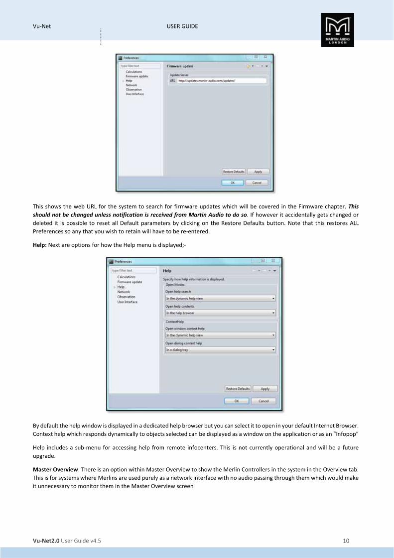
Firmware update: The next option is Firmware update;‐
Vu‐Net USER GUIDE
Vu‐Net2.0 User Guide v4.5 10
…………
This shows the web URL for the system to search for firmware updates which will be covered in the Firmware chapter. This
should not be changed unless notification is received from Martin Audio to do so. If however it accidentally gets changed or
deleted it is possible to reset all Default parameters by clicking on the Restore Defaults button. Note that this restores ALL
Preferences so any that you wish to retain will have to be re‐entered.
Help: Next are options for how the Help menu is displayed;‐
By default the help window is displayed in a dedicated help browser but you can select it to open in your default Internet Browser.
Context help which responds dynamically to objects selected can be displayed as a window on the application or as an “Infopop”
Help includes a sub‐menu for accessing help from remote infocenters. This is not currently operational and will be a future
upgrade.
Master Overview: There is an option within Master Overview to show the Merlin Controllers in the system in the Overview tab.
This is for systems where Merlins are used purely as a network interface with no audio passing through them which would make
it unnecessary to monitor them in the Master Overview screen
Vu‐Net USER GUIDE
Vu‐Net2.0 User Guide v4.5 11
…………
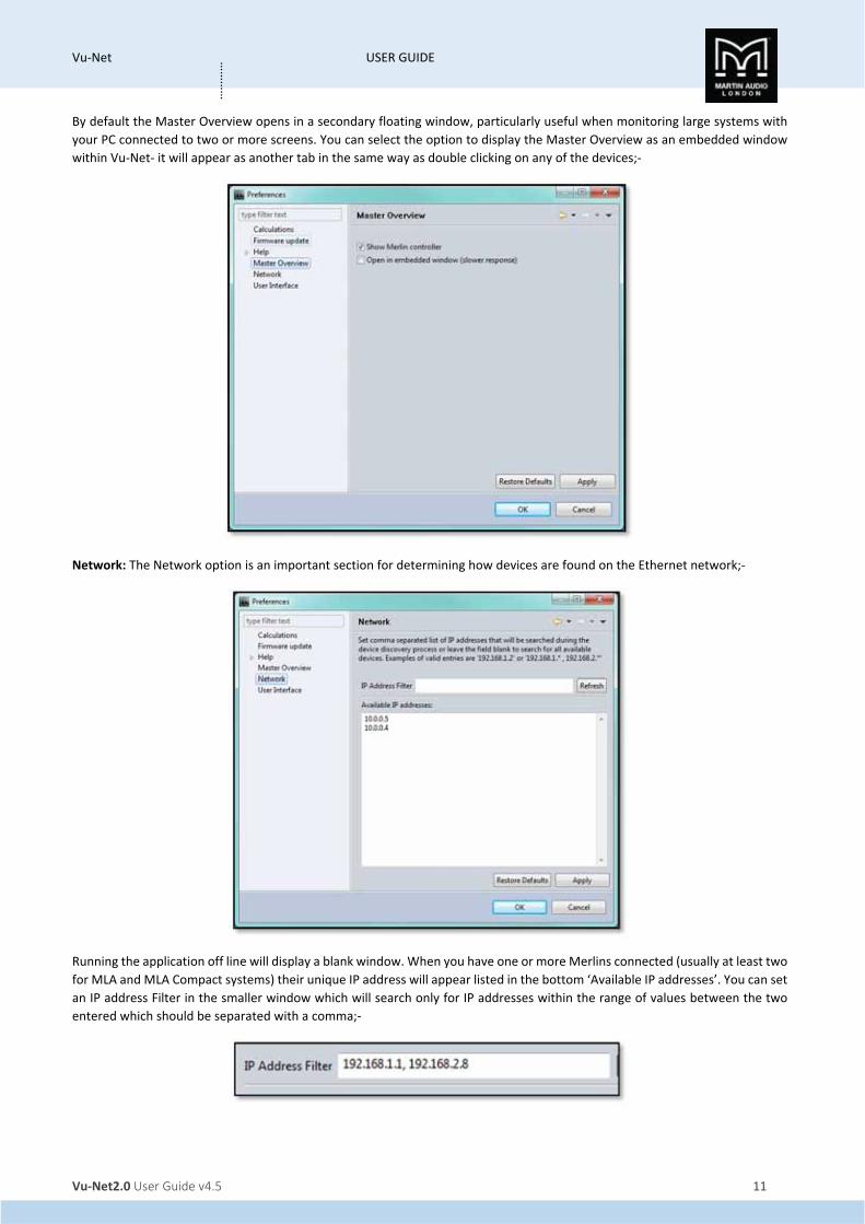
By default the Master Overview opens in a secondary floating window, particularly useful when monitoring large systems with
your PC connected to two or more screens. You can select the option to display the Master Overview as an embedded window
within Vu‐Net‐ it will appear as another tab in the same way as double clicking on any of the devices;‐
Network: The Network option is an important section for determining how devices are found on the Ethernet network;‐
Running the application off line will display a blank window. When you have one or more Merlins connected (usually at least two
for MLA and MLA Compact systems) their unique IP address will appear listed in the bottom ‘Available IP addresses’. You can set
an IP address Filter in the smaller window which will search only for IP addresses within the range of values between the two
entered which should be separated with a comma;‐

Vu‐Net USER GUIDE
Vu‐Net2.0 User Guide v4.5 12
…………
This could be used if you have two systems running on the same Ethernet network and need to control them independently.
Only devices with their IP address set to values within the filter range will be found and the system will work completely
independently as if there were no other devices on the network.
Note that if you are connecting to MLA Mini, DD12 or PSX via their integral USB port, no IP address will be visible. This function
is only applicable to networks supported by Merlins or Ethernet connected devices such as the CDD Live range.
User Interface: The final option in the Preferences window is User interface;‐
This allows customisation of certain functions within the application.
Increment Values;‐
These allow the default increment values for both Gain and Delay to be changed as required. The default for Gain is 0.5dB but
the options are for increments of 0.1, 0.2, 0.25, 0.5 or 1dB.
For delay, the default is 25ms, the options are 0.1, 0.2, 0.25, 0.5 or 1ms.
The Windows Power Option;‐
Allows Vu‐Net to prevent Windows from implementing changes to the power settings that can effect network operation. This
should be left checked unless there is a very specific need to do otherwise

Vu‐Net USER GUIDE
Vu‐Net2.0 User Guide v4.5 13
…………
Finally there are a number of options for how the system diagram is displayed;‐
This is intended to reduce the number of lines on the System Diagram overview which may get cluttered in large systems with a
high number of devices.
Tools
The tools menu;‐
This has three important functions for system operation.
Preset Loader is used to upload EQ optimisations into the arrays.
Firmware Update Wizard is used to check and upload the latest firmware into the system components.
MLA/MLD Conversion Tool is used to convert the amplifier modules used in MLA and MLD cabinets from one type to another.
Mechanically and electrically these are identical, they simply need a firmware conversion so the system is aware of what type of
enclosure they are powering. An MLD module can be converted to an MLA or more commonly an MLA module to an MLD.
Window
The Window menu is used to determine which sections of the project window are displayed;‐
The System Diagram is always visible but the other windows can be closed and reopened as required. By default they are all open
but if closed they can be reopened by selecting them from the Window menu. The Reset Perspective option will restore the
project layout to the default view.
Help
The help menu has a number of options;‐
Vu‐Net USER GUIDE
Vu‐Net2.0 User Guide v4.5 14
…………
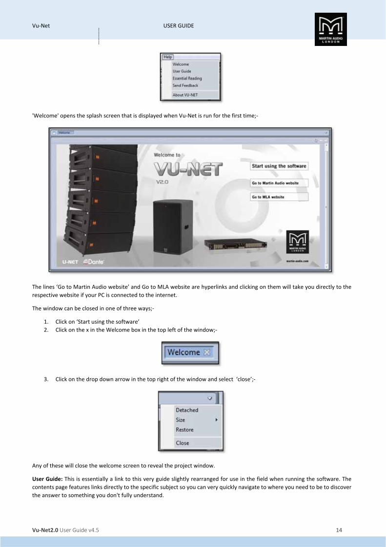
'Welcome' opens the splash screen that is displayed when Vu‐Net is run for the first time;‐
The lines ‘Go to Martin Audio website’ and Go to MLA website are hyperlinks and clicking on them will take you directly to the
respective website if your PC is connected to the internet.
The window can be closed in one of three ways;‐
1. Click on ‘Start using the software’
2. Click on the x in the Welcome box in the top left of the window;‐
3. Click on the drop down arrow in the top right of the window and select ‘close’;‐
Any of these will close the welcome screen to reveal the project window.
User Guide: This is essentially a link to this very guide slightly rearranged for use in the field when running the software. The
contents page features links directly to the specific subject so you can very quickly navigate to where you need to be to discover
the answer to something you don't fully understand.
Vu‐Net USER GUIDE
Vu‐Net2.0 User Guide v4.5 15
…………
Essential Reading: This opens a pdf document that outlines the new features in the latest version of Display 2.2 and how they
affect their implementation in Vu‐Net.
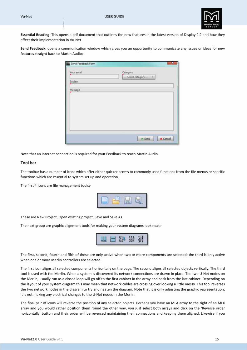
Send Feedback: opens a communication window which gives you an opportunity to communicate any issues or ideas for new
features straight back to Martin Audio;‐
Note that an internet connection is required for your Feedback to reach Martin Audio.
Tool bar
The toolbar has a number of icons which offer either quicker access to commonly used functions from the file menus or specific
functions which are essential to system set up and operation.
The first 4 icons are file management tools;‐
These are New Project, Open existing project, Save and Save As.
The next group are graphic alignment tools for making your system diagrams look neat;‐
The first, second, fourth and fifth of these are only active when two or more components are selected; the third is only active
when one or more Merlin controllers are selected.
The first icon aligns all selected components horizontally on the page. The second aligns all selected objects vertically. The third
tool is used with the Merlin. When a system is discovered its network connections are drawn in place. The two U‐Net nodes on
the Merlin, usually run as a closed loop will go off to the first cabinet in the array and back from the last cabinet. Depending on
the layout of your system diagram this may mean that network cables are crossing over looking a little messy. This tool reverses
the two network nodes in the diagram to try and neaten the diagram. Note that it is only adjusting the graphic representation;
it is not making any electrical changes to the U‐Net nodes in the Merlin.
The final pair of icons will reverse the position of any selected objects. Perhaps you have an MLA array to the right of an MLX
array and you would rather position them round the other way, you just select both arrays and click on the ‘Reverse order
horizontally’ button and their order will be reversed maintaining their connections and keeping them aligned. Likewise if you

Vu‐Net USER GUIDE
Vu‐Net2.0 User Guide v4.5 16
…………
wish to reverse the vertical order, position DSX subs under an MLA Compact array when the diagram has the subs on top, select
the required components and click the ‘Reverse order vertically button’
Discover Devices is the method by which U‐Net connects to all system components once all hardware connections have been
made;‐
This will interrogate the U‐Net network and find all connected devices opening Wizards for each type of device; MLA & MLD,
MLX, MLA Compact, DSX, MLA Mini, MSX, DD12, CDD Live and Merlin. All devices on the same U‐Net loop will be grouped
together by type by the discovery process. Note that Vu‐Net will discover devices regardless of how they are connected, either
directly by USB in the case of MLA Mini, DD12 or PSX, via Ethernet for CDD Live and CSX Live, or over a U‐Net loop via a Merlin
acting as a network bridge
Master Overview;‐
Gives an overview of all devices in the project displaying all bargraph level meters giving access to essential functions such as
gain, mute and Delay and with a link to EQ functions. This is designed to be used once a show is in progress to allow easy
monitoring of an entire system from a single page. The Master Overview is opened as another tab next to the Project System
diagram and any other open arrays or components.
Show Mode;‐
As the name suggests, this is intend for use during a show once set‐up is complete. It changes the operation of the Mute function
for all products. When disabled, all mutes can be selected and de‐selected freely, when show mode is active;‐
Any click on a mute button will bring up a pop‐up window asking you to confirm that you want to Mute or Un‐Mute that array
or channel. It also disables the output cell check function, see later in this guide for details
The zoom function;‐
Allows you to adjust the system diagram size to suit the complexity of the system on your PC display. The ‘‐‘ and ‘+’ buttons will
decrease or increase the zoom in increments of 25%. Alternatively you can use the drop‐down box to select either 10%, 25%,
50%, 100%, 125%, 150%, 200%, 300%, 400%, 600% or 800%. Particularly useful are ‘Page’ which will zoom to the maximum size

Vu‐Net USER GUIDE
Vu‐Net2.0 User Guide v4.5 17
…………
that the page will allow, ‘Width’ which will zoom to the maximum width of the diagram and ‘Height’ which will maximise the size
to fit the height of the diagram.
Mute is essentially an “emergency" function if something is causing severe noise through the system you can click on the mute
button;‐
This will bring up the following window;‐
As you can see it is a very drastic measure which will shut down the entire system which is why it should be considered as an
emergency measure only and not an everyday means for muting the system. If you are sure you wish to proceed you can select
‘Yes’ if not click on ‘No’ and the window will disappear, the audio will remain routed. This function mutes every input and output
on connected Merlins and every zone on all arrays. Once used there is no global un‐mute, all Merlins and arrays will have to be
individually un‐muted. Note that Show Modes does not change operation of the System Mute, the confirmation window will
always appear.
Our advice is never to leave a system muted within Vu‐Net, always use a mute that can be defeated manually such as a Merlin
output. If a system has been muted within Vu‐Net and for some reason you lose network connectivity you will be unable to un‐
mute and will have an unusable system!
System Disconnect
This will disconnect the project from the hardware in the system. A Window will pop up giving you a selection of options;‐
As you can see, once you are disconnected from the system you are unable to make any changes to the project, this is to ensure
compatibility and accurate synchronisation when you reconnect. You have the option to reconnect straight from the window or
can close the project with or without saving. Finally you can minimise the project. This is particularly useful if you have
disconnected to switch from a Wi‐Fi to a hard‐wired connection, having minimised to can access the PC network setting to make
the switch to a cable Ethernet connection.
Vu‐Net USER GUIDE
Vu‐Net2.0 User Guide v4.5 18
…………
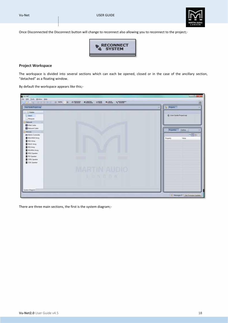
Once Disconnected the Disconnect button will change to reconnect also allowing you to reconnect to the project;‐
Project Workspace
The workspace is divided into several sections which can each be opened, closed or in the case of the ancillary section,
“detached" as a floating window.
By default the workspace appears like this;‐
There are three main sections, the first is the system diagram;‐

Vu‐Net USER GUIDE
Vu‐Net2.0 User Guide v4.5 19
…………
This window will show all array components on the network and is used for all configuration changes and system monitoring.
The palette on the left is used to manually enter system components when working off line (in normal use, Device Discovery is
used to find all connected components). If you need to maximise the workspace the palette can be minimised by clicking on the
white triangle in the top left corner of the palette;‐
The overall size of the System Diagram can be increased or decreased by clicking and holding on the gap between its right‐hand
edge and the left hand edge of the other windows. You can then drag either left or right to adjust the relative sixes of the
windows. Alternatively, the white drop‐down arrow gives you the option to maximise the screen. The other windows will not be
closed; they will be represented by an icon on the right side of the page with the option to restore. Clicking restore will return
the windows to their previous state.
On the right side of the window are two further windows;‐

Vu‐Net USER GUIDE
Vu‐Net2.0 User Guide v4.5 20
…………
The first is a project overview window showing the open project. The window can be maximised, detached or closed by clicking
on the white arrow in the top right corner. The project icon can be expanded if they have a small arrow to the left (a project that
doesn’t yet have any components added or discovered will not show an arrow). This will then show all connected components
as in the picture above. Arrays will have a further arrow which if clicked will show all individual cabinets. This screen grab shows
an enlarged project window in which the User Guide system has been expanded and one of the MLA arrays and one of the MLX
arrays have also been expanded;‐
The final window by default has Properties and Outline available but by using the ‘Show View’ option in the Window menu, you
can also select Network Status. This shows all three options available;‐
Any of the three options can be viewed by clicking on the relevant button. As with the Project window any of the selected options
can be detached as a floating window, maximised or closed by clicking on the white arrow. If all options in the window are closed
the project window will fill the space, if that is also closed the Project window will fill the space.
Vu‐Net USER GUIDE
Vu‐Net2.0 User Guide v4.5 21
…………
The Properties window will show the properties for any element selected in the System diagram. The example above shows the
properties for a Merlin in an off line project. There are a number of options available for the Properties display selected by the
icons in the top right corner of the window;‐
The first pins the Property view of the selected element so it remains on view regardless of whether an alternative element or
even project is selected. A second click on the icon will un‐pin the view and any new selected element can have its properties
displayed.
The next is the Show Categories button which is selected by default. This shows the categories for each of the properties and
gives the option to display or hide any of the properties in a particular category by clicking on the small arrow leaving just the
category heading.
The third icon displays advanced properties for the selected element.
The final icon will reset any modified properties to their default values.
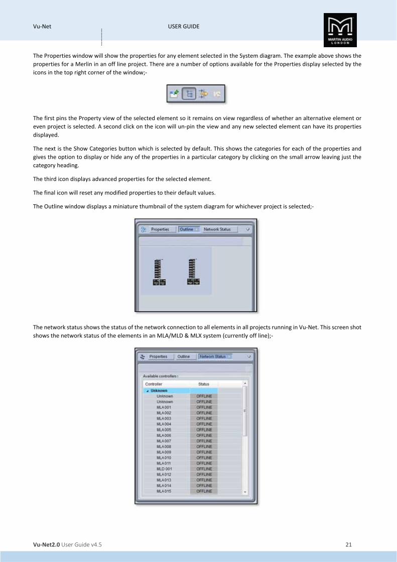
The Outline window displays a miniature thumbnail of the system diagram for whichever project is selected;‐
The network status shows the status of the network connection to all elements in all projects running in Vu‐Net. This screen shot
shows the network status of the elements in an MLA/MLD & MLX system (currently off line);‐

Vu‐Net USER GUIDE
Vu‐Net2.0 User Guide v4.5 22
…………
Working Offline Before we move on to look at adding elements to projects it is important to understand the difference between working off line
and normal on‐line operation at an event. When working off line the Palette allows you to drop elements into the System
Diagram, you can open arrays, speakers and Merlins as you would for an on‐line system. This is useful as a means to get used to
system operation in Vu‐Net but very little beyond that. Unlike some systems you CANNOT create a system design off line and
connect to a system on site. When connecting to a system you have to use Device Discovery which searches all available
connected devices for system elements and automatically drops them into the system diagram showing their Ethernet and Vu‐
Net Connections. This is vital as every Vu‐Net element has a unique factory set IP address which Vu‐Net records so it can provide
real‐time monitoring of the system and can display the status of every device. If for example you re‐connect to a system having
used it on one day and shut down over night, Vu‐Net will be able to detect that every cabinet has been turned back on and the
status of all parameters of every DSP. We will show how to introduce all available elements into a project off line but will cover
Device Discovery and on‐line operation in a later chapter.
Adding Merlin, MLA, MLD and MLX
Adding any devices to a System diagram is a simple case of clicking on the required item in the Palette;‐
Then click on the System Diagram workspace. The cursor will have a small white box with a cross in the centre prompting you to
click where you wish to deposit the device. Here we see a new Merlin added to a project;‐
The four black squares in the corners indicate that the device is still selected which is the default when a new element is added
to a project. The most useful thing about this is that it gives you the opportunity to move it to exactly where you need it simply
by using a click‐drag‐drop movement. A click anywhere else in Vu‐Net will de‐select the Merlin.
Adding an MLA/MLD array is done by clicking on the icon and then in the project window, you will see the following window;‐

Vu‐Net USER GUIDE
Vu‐Net2.0 User Guide v4.5 23
…………
Enter the number of MLD required in the array. In the majority of systems this will be one or two. They will automatically be
added to the bottom of the array.
Next this window appears;‐
Note that you must enter the total number of cabinets including the MLD, NOT the number of MLA. The array will appear in the
workspace like this;‐
The array is greyed‐out to show that it is off line. Note that the largest array that can be added is a total of 24 cabinets which
matches the maximum flown array from the flying grid. If you enter a number higher than 24 Vu‐Net will enter a 24 box array.
MLX is added in the same way, you will see the same window requesting the total quantity of cabinets. Here is a six box array of
MLX, note that in off‐line mode sub arrays are always entered a single column of cabinets as if flown. Device Discovery of an on‐
line system gives you the option to specify ground stacked and draw the array exactly as it has been physically positioned;‐
Adding MLA Compact & DSX
MLA Compact is added in exactly the same way, the only difference is that as there is no downfill enclosure you are simply asked
the total number of cabinets;‐
Vu‐Net USER GUIDE
Vu‐Net2.0 User Guide v4.5 24
…………
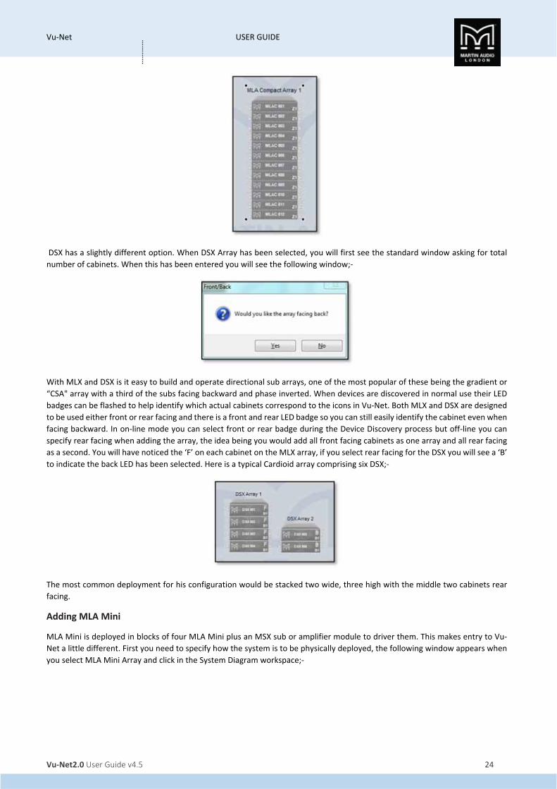
DSX has a slightly different option. When DSX Array has been selected, you will first see the standard window asking for total
number of cabinets. When this has been entered you will see the following window;‐
With MLX and DSX is it easy to build and operate directional sub arrays, one of the most popular of these being the gradient or
“CSA" array with a third of the subs facing backward and phase inverted. When devices are discovered in normal use their LED
badges can be flashed to help identify which actual cabinets correspond to the icons in Vu‐Net. Both MLX and DSX are designed
to be used either front or rear facing and there is a front and rear LED badge so you can still easily identify the cabinet even when
facing backward. In on‐line mode you can select front or rear badge during the Device Discovery process but off‐line you can
specify rear facing when adding the array, the idea being you would add all front facing cabinets as one array and all rear facing
as a second. You will have noticed the ‘F’ on each cabinet on the MLX array, if you select rear facing for the DSX you will see a ‘B’
to indicate the back LED has been selected. Here is a typical Cardioid array comprising six DSX;‐
The most common deployment for his configuration would be stacked two wide, three high with the middle two cabinets rear
facing.
Adding MLA Mini
MLA Mini is deployed in blocks of four MLA Mini plus an MSX sub or amplifier module to driver them. This makes entry to Vu‐
Net a little different. First you need to specify how the system is to be physically deployed, the following window appears when
you select MLA Mini Array and click in the System Diagram workspace;‐

Vu‐Net USER GUIDE
Vu‐Net2.0 User Guide v4.5 25
…………
1. Flown refers to a system with MLA Mini flown below the MSX sub using the flying frame and transition grid. The maximum
configuration for this mode is three sets of Mini and MSX (twelve MLA Mini cabinets).
2. Flown in Front of MSX allows the maximum flown array of MLA Mini which is sixteen cabinets and allows for configurations
with the MLA Mini flown using the flying grid with up to four MSX on a second grid flown behind the Mini.
3. Flown with Ground stack MSX, MSX vertical stack is from four to sixteen MLA Mini flown using a Universal Bracket
(maximum four cabinets) or flying grid with the MSX on the ground under the array stacked on top of each other vertically.
4. Flown with Ground stack MSX, MSX horizontal row is from four to sixteen MLA Mini flown using a Universal Bracket
(maximum four cabinets) or flying grid with the MSX on the ground under the array in a row horizontally.
5. Ground Stack on MSX is possible with one or two MSX and four or eight MLA Mini.
6. Ground Stack next to MSX, MSX vertical stack allows ground stack arrays with the MLA Mini stacked directly onto the
ground, perhaps at the front of a stage for example, using the flying grid and the ground stack base plate. Two systems
(eight MLA Mini) can be used in this configuration. The MSX would be placed to one side of the MLA Mini array stacked on
top of each other when two are used with eight MLA Mini.
7. Ground Stack next to MSX, MSX horizontal array allows ground stack arrays as option 6 but with the MSX to one side of the
MLA Mini array placed horizontally in a row when two are used with eight MLA Mini.
8. Pole Mount adds a single system of one MSX with four MLA Mini above on a pole mount.
9. Four Single fills is for using the MLA Mini individually as stage front fills for example.
10. Two double fills pairs the Mini to create two fills for various applications.
If you have selected the deployment options 1, 2, 3, 4, 5, 6 or 7 you will next be asked to select the number MLA Mini cabinets;‐
If you select a number greater than is possible for the desired deployment Vu‐Net will automatically restrict the number to the
maximum allowed.
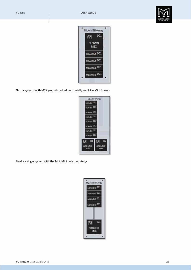
Here are a few examples of MLA Mini arrays, first a single flown array;‐
Vu‐Net USER GUIDE
Vu‐Net2.0 User Guide v4.5 26
…………
Next a systems with MSX ground stacked horizontally and MLA Mini flown;‐
Finally a single system with the MLA Mini pole mounted;‐

Vu‐Net USER GUIDE
Vu‐Net2.0 User Guide v4.5 27
…………
Adding DD12
DD12 can be added individually dragged across from the device menu;‐
Adding PSX
PSX is also added in the same way, clicking on PSX in the Devices list and clicking in the system diagram workspace;‐
As the system is off line there is no preset showing and the satelite cabinet is a generic shape. When used on line and selecting
one of the three factory presets for either DD6, CD12 or XD15 the thumbnail picture reflects the selected cabinet.
Adding CDD Live
There are two CDD Live options in the Devices list, one for CDD Live full range cabinets and a second for the CSX Subwoofer from
the range. Adding CDD Live will bring up the following window alling you to select one of the three full range models, CDD Live8,
CDD Live12 or CDD Live15;‐
Type 1 to select CDD Live8, 2 to seelct CDD Live12 and 3 to select CDD Live15. Here we have added one of each product;‐

Vu‐Net USER GUIDE
Vu‐Net2.0 User Guide v4.5 28
…………
Similarly, the choice of CSX Subs brings up an option window;‐
Typing 1 adds a CSX Live118 and 2 adds a CSX Live218;‐
Arranging the Array components
Vu‐Net has a number of tools available to help keep the system diagram looking tidy.
Selecting elements can be done in a variety of ways. The most obvious is a single mouse click; the selected object will show the
small black squares in the four corners around it. A subsequent click anywhere else will de‐select the object, as will click on a
second object. The selected element can also be changed using the left, right, up and down arrow keys, the object selected will
jump in the direction of the keys.

Vu‐Net USER GUIDE
Vu‐Net2.0 User Guide v4.5 29
…………
Selecting multiple objects can be done two ways. First you can draw a box around multiple items. Click and hold in the corner of
a group of objects and drag over all of them diagonally. A box will appear round all selected items until you release the mouse
button whereupon all objects within the box will be selected. You can draw the box from any corner in any direction.
If you need to repeat this action several times you can select the Marquee tool from the Palette menu which changes the mouse
cursor to a cross and enables box‐drawing mode. Click on the Select icon in the Palette to return to normal select mode.
Secondly you can click to select an element then press and hold either Ctrl or Shift and click on all other elements you wish to
select. Note that you can use a combination of selection modes if necessary; use the box‐drawing method initially then Ctrl or
Shift click to add additional elements to the selection.
Deselecting an element from a multiple selection must be done with Ctrl + click. With a multiple selection there is always one
primary element, by default the last one added to the selection. This will have the familiar black squares in the corners; all other
selected items will have white squares. You can change the primary element by a further Shift + Click on an object. Deselecting
all objects is done in the same way as a single item by clicking anywhere on the work surface.
The icons on the tool bar offer quick and easy alignment of multiple objects, there are five tools available;‐
The first aligns objects horizontally, here is a before and after of four arrays that have been selected;‐
In the left hand shot the arrays have been positioned roughly in a line and all selected the right hand shot shows them all neatly
lined up in a horizontal line.
The second allows alignment in the vertical;‐

Vu‐Net USER GUIDE
Vu‐Net2.0 User Guide v4.5 30
…………
Again the arrays are not very well aligned but a simple click of the vertical alignment button and they are perfectly in line.
The fourth button will swap the horizontal position of all selected elements;‐
The left hand shot shows a system drawn with the left and right arrays placed on the wrong sides, the right shot has been
corrected with the reverse order horizontally button.
The fifth button swaps the order of all selected items in the vertical plane;‐

Vu‐Net USER GUIDE
Vu‐Net2.0 User Guide v4.5 31
…………
The third button applies only to the Merlin. When a system is discovered on line all U‐Net connections are shown from the Merlin
to all arrays;‐
The U‐Net ports on the Merlin are on the top and bottom of the Merlin icon, in most cases this allows Vu‐Net to draw the system
connections neatly as in the above example but they may be instances where the position of the arrays and complexity of the
system means that the network connections cross and the system diagram looks untidy;‐
If this is the case, select the Merlin and click on the ‘Reverse U‐Net ports’ button and the port position is reversed in the system
diagram hopefully making the network connections look neater;‐

Vu‐Net USER GUIDE
Vu‐Net2.0 User Guide v4.5 32
…………
Note: this button reverses the port positions in the system diagram ONLY. It does NOT make and electrical changes to the two
U‐Net ports, it is purely and simply a graphical change.

Vu‐Net USER GUIDE
Vu‐Net2.0 User Guide v4.5 33
…………
Device Discovery The normal method for operating a system following completing the system rigging and connection is to run Vu‐Net is to run
Device Discovery. It is good practice to check your network connectivity, first by using the network icon on the PC task bar which
should show connection to your system (it will flag that there is no internet connectivity which can be ignored). Then by going
into Preferences and selecting ‘Network’ and making sure that the Available IP addresses window has an IP address for every
Merlin in use with your system. If all is ok you can proceed by clicking on the Discover Devices button;‐
Assuming everything is OK with your network connection you will see the following window;‐
The meter bar will gradually move across until it is completely green and all devices have been found. This may take a few seconds
on bigger systems with large arrays of many cabinets.
There are a couple of other windows that may appear at this stage, as well as discovering all devices on the network and
identifying their type and IP address, Vu‐Net also checks their Firmware to ensure it matches the latest version stored in its
internal Firmware database. If it detects an older Firmware version you will see the following window;‐
For more detail on Firmware updates please see the relevant Firmware chapter.
Finally, it is possible you may see this window;‐
This would indicate a problem up‐stream of the Merlin; are the cabinets powered? Are all the network connections made? Is
one of the Merlins set to Static IP instead of Dynamic? Can you see two green U‐Net LEDs on all devices including the Merlin? If
everything is ok try power cycling the Merlin and run Device Discovery again.
Note: It is not essential to have the complete system wired before you run Device Discovery; for example, you may wish to check
each array individually as they are rigged so they can be flown out which is perfectly acceptable. Every subsequent press of
Device Discovery will find any new elements that have been introduced to the network ignoring those already discovered.

Vu‐Net USER GUIDE
Vu‐Net2.0 User Guide v4.5 34
…………
Once Device Discovery has completed its scan you will see the following window;‐
This shows a list of all connected devices found grouped into categories; Merlin Controllers, MLA, MLD, MLX et cetera. Each
individual U‐Net network created either by a Merlin or USB connected device (such as an MSX or DD12) will create an individual
window with the IP address shown at the top. All devices connected to that U‐Net loop will be listed grouped by type.
Next press the ‘Run Wizard’ button and an individual Wizard will run for all categories, the first will be MLA, MLD or MLA
Compact;‐
If you have more than one array of each type of cabinet on the same U‐Net loop you have the opportunity to divide them into
two or more arrays as required. Use the up/down button to select the number of arrays then change the number of cabinets in
each array to match what you physically have connected;‐

Vu‐Net USER GUIDE
Vu‐Net2.0 User Guide v4.5 35
…………
If the total does not match what Vu‐Net has discovered the numbers will be flagged in red. Click next and you will see a new
window showing the array or arrays;‐
If you have more than one array the first step is to use the ‘ALL ON’ button which will illuminate all the LED badges on the array
to check that the Vu‐Net arrays match the physical deployment. If there are any errors the cabinets can be dragged and dropped
to the correct positions or array. If you only have one array it is still worth flashing all LED’s to see the look on the faces of the
lighting technicians when they see LED lighting over which they have no control…
Next click the ‘BY ONE’ button. This will flash the LEDs in sequence from top to bottom. As the U‐Net network is bi‐directional it
is entirely possible that the arrays could have been discovered starting with what is actually the last cabinet in the array. If this
has happened you will see the LEDs on the actual cabinets flashing from bottom to top and you MUST click ‘REVERSE ORDER’ to

Vu‐Net USER GUIDE
Vu‐Net2.0 User Guide v4.5 36
…………
get it flashing the right way up. This is essential so that Vu‐Net knows that the array is orientated the right way, failure to do this
could result in an EQ optimisation being loaded upside down producing an array attempting to produce a coherent, flat response
for an audience 30 meters or so up in the air!
Next you will see the following window for any connected MLX or DSX;‐
By default the ‘Arrangement’ will be displayed as ‘Flown’ therefore the ‘No of columns’ field will show 1. If you click on ‘Flown’
it will toggle to ‘Ground Stacked’ and if this is how your subs are deployed you can select the number of columns to reflect in Vu‐
Net exactly how they are positioned;‐
This could even mean making the columns equal the number of enclosures where a broadside array is being deployed;‐

Vu‐Net USER GUIDE
Vu‐Net2.0 User Guide v4.5 37
…………
Once you have selected the array configuration select ‘Next’ and you will see a similar window to the one for MLA, MLD or MLA
Compact;‐
Repeat the process of flashing LED badges to ensure that the cabinets are in the correct order. If any are in the wrong position
use drag and drop to reposition them. For a conventional sub stack this may not be vital as the parameters are likely to be
identical for all cabinets but for cardioid or broadside arrays it is essential to ensure that they are correct so delay and other
parameters applied are directed to the correct cabinet. At this stage you can also change the LED badge to flash on the rear.
They are configured for the front LED by default signified by the ‘F’ on the thumbnails. Double click directly on the badge and
you will see the ‘F’ become a ‘B’ to signify the back LED. This will flash instead of the front LED when selected. Note that selecting
‘B’ does not change any internal parameters that may be required for cardioid array operation, if simply changes the LED indicator
from the front to the rear for cabinet identification. All parameter changes must still be entered manually;‐

Vu‐Net USER GUIDE
Vu‐Net2.0 User Guide v4.5 38
…………
Once you are satisfied with the sub layout click on ‘Next’ and the synchronisation of all elements on the U‐Net loop will
commence;‐
It possible (although unlikely) that one or more element will not synchronise correctly on the first pass in which case there will
be a Red ‘Fail’ in the Result column for that device. If this occurs wait until the rest of the synchronisation is finished and click on
the Synchronise button for that device in the extreme right column. The device will attempt a further synchronisation which
should result in a success and a green ‘OK’. A complete successful synchronisation will appear like this;‐

Vu‐Net USER GUIDE
Vu‐Net2.0 User Guide v4.5 39
…………
This means that all settings residing in the DSP of all components have been uploaded into Vu‐Net so you have a completely
accurate picture of exactly how the system is configured on your tablet PC. You can click ‘Finish’ and a further ‘Finish’ on the
Device Discovery Report window. Repeat the procedure for all connected Merlins which will all have their own U‐Net ring of
elements.
Once this is completed the Vu‐Net workspace will appear as shown;‐

Vu‐Net USER GUIDE
Vu‐Net2.0 User Guide v4.5 40
…………
Device Discovery MLA Mini Device Discovery for MLA Mini is a little more involved as it is necessary to determine the deployment to ensure that the amplifier
module is correctly configured, particularly between ground stacked and flown options as the software compensates for the fact
that the cabling is done in different directions; for flown systems the cables attach from above so the longest NL4 on the Speaker
cable loom going to the lowest cabinet, the opposite is true for ground stacked systems where the speaker loom comes from
below with the longest NL4 reaching the upper‐most cabinet.
Here is a small MLA Mini system with a pair of MSX Subs and 8 MLA Mini. We have connected via the USB connection on one of
the MSX and the two are linked together with U‐Net cables;‐
If we click on 'Run Wizard' we see the following Window;‐
The first task is to determine how many arrays are deployed. By default Display assumes a single array comprising all of the MSX
discovered, if the system is actually stereo for example we need to select 2 in the 'Number of ARRAYS' box;‐

Vu‐Net USER GUIDE
Vu‐Net2.0 User Guide v4.5 41
…………
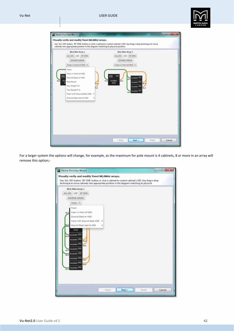
This now shows two arrays each comprising of a single MSX and 4 MLA Mini. Click 'Next' and the next window is where we select
the desired deployment;‐
This shows the two MLA Mini array which are deployed in the fault methods of Flown in front of MSX. The drop‐down box shows
all other options;‐
Vu‐Net USER GUIDE
Vu‐Net2.0 User Guide v4.5 42
…………
For a larger system the options will change, for example, as the maximum for pole mount is 4 cabinets, 8 or more in an array will
remove this option;‐

Vu‐Net USER GUIDE
Vu‐Net2.0 User Guide v4.5 43
…………
There are however additional options for ground stacked systems of eight or more MLA Mini, the black arrow against these
brings out the option for stacking the MSX either horizontally or vertically;‐
Selecting the various modes will change the array thumbnails accordingly and also importantly shows how the arrays should be
cabled. This is particularly important as flown systems are cabled the opposite way to ground stacked with the longest NL4 cable
reaching down to the lowest cabinet. For example Flown will appear like so;‐

Vu‐Net USER GUIDE
Vu‐Net2.0 User Guide v4.5 44
…………
Ground stacked on MSX which is available for up to 8 cabinets appears like this, not the cable which unlike flown has the longer
NL4s running up to the top cabinet;‐
Pole mounted (only available for four cabinets), adds a pole;‐

Vu‐Net USER GUIDE
Vu‐Net2.0 User Guide v4.5 45
…………
There are two options to use Mini as front fills, either as four single cabinets or two pairs;‐
Finally you can ground stack the Mini next to the MSX;‐

Vu‐Net USER GUIDE
Vu‐Net2.0 User Guide v4.5 46
…………
Once you have selected the appropriate deployment you can check the arrays by flashing the LED's on the front of the MSX as
with MLA and MLA Compact cabinets. You can select 'ALL ON' to illuminate every cabinet in an array useful for identifying which
array is which where two or more are in use, and 'BY ONE' which will flash all MSX in an array sequentially so you can check that
they are in the correct order;‐
If they are not they can be drag and dropped into the correct positions until the Vu‐Net flashing sequence matches the real‐
world cabinets. Clicking on one MSX will grey out all others until it has been dragged and dropped to the desired position;‐

Vu‐Net USER GUIDE
Vu‐Net2.0 User Guide v4.5 47
…………
Once the cabinet sequence is corrected you can proceed by clicking next and synchronising the system;‐
Once complete the arrays will appear on the System Diagram window with the thumbnail representing how you have selected
the system deployment. Here is an eight box system flown from MSX;‐

Vu‐Net USER GUIDE
Vu‐Net2.0 User Guide v4.5 48
…………
This is a flown system with the MSX flown behind the Mini;‐
Eight mini ground‐stacked on their MSX;‐
Vu‐Net USER GUIDE
Vu‐Net2.0 User Guide v4.5 49
…………
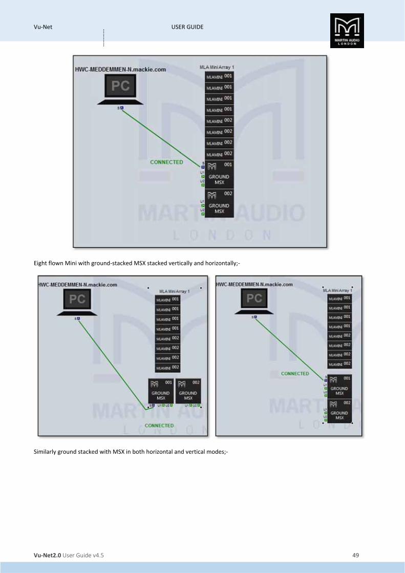
Eight flown Mini with ground‐stacked MSX stacked vertically and horizontally;‐
Similarly ground stacked with MSX in both horizontal and vertical modes;‐

Vu‐Net USER GUIDE
Vu‐Net2.0 User Guide v4.5 50
…………

Vu‐Net USER GUIDE
Vu‐Net2.0 User Guide v4.5 51
…………
On line operation
Note the differences from the off line mode of operation. First in the top tight corner you can see the indication that the Merlin
and connected speakers are on line;‐
In the right hand corner we have selected network status and we now see all connected elements showing as Online;‐
We now have the facility to Disconnect from the system whenever necessary, at the end of the night when a show is finished for
example. Click on the ‘DISCONNECT’ button;‐
You will see the Disconnecting System Window appear;‐
Next you will see the following message;‐
Vu‐Net USER GUIDE
Vu‐Net2.0 User Guide v4.5 52
…………
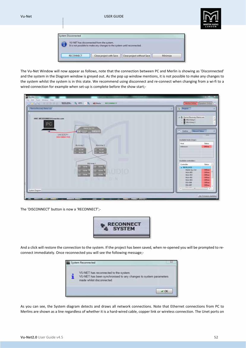
The Vu‐Net Window will now appear as follows, note that the connection between PC and Merlin is showing as 'Disconnected'
and the system in the Diagram window is greyed out. As the pop up window mentions, it is not possible to make any changes to
the system whilst the system is in this state. We recommend using disconnect and re‐connect when changing from a wi‐fi to a
wired connection for example when set‐up is complete before the show start;‐
The ‘DISCONNECT’ button is now a ‘RECONNECT’;‐
And a click will restore the connection to the system. If the project has been saved, when re‐opened you will be prompted to re‐
connect immediately. Once reconnected you will see the following message;‐
As you can see, the System diagram detects and draws all network connections. Note that Ethernet connections from PC to
Merlins are shown as a line regardless of whether it is a hard‐wired cable, copper link or wireless connection. The Unet ports on

Vu‐Net USER GUIDE
Vu‐Net2.0 User Guide v4.5 53
…………
individual devices also show the network integrity. Good connections will show as a green U1 and U2 port. A faulty or missing
connection between devices in an array will be shown as either a grey (no connection) or a red (connection with network errors)
U‐Net port. By hovering your mouse over a port displaying an error you will see details outlining the nature of the issue;‐
In most cases this is not critical as a U‐Net topology is a redundant ring so if there is a break in the network connection, every
device will still remain on line as the A cabinet or array off‐line will appear in red, an individual off line cabinet will be shown at
the position in the array;‐
The network is monitored in real time so as soon as any network or cabinet issues have been resolved the connections and
cabinets will return to the regular colour scheme;‐

Vu‐Net USER GUIDE
Vu‐Net2.0 User Guide v4.5 54
…………
Right‐Click menu
Access to array or Merlin functions are achieved in two ways; double clicking or right clicking, first we will look at the options
available when selecting an element with a right mouse click as there are some configuration options that you may need to select
first from this page. The right click menu varies according to the device selected, ;‐
From left to right these are the right‐click menus for the Merlin, an MLA or MLA Compact Array and a DD12 or PSX
‘Open’ will open the full configuration page in exactly the same way as a double click
'Load' for a Merlin offers two options, either load a saved Merlin Configuration file created using the Save function, or load a
Preset file which will import a binary file created in XTA's Library Manager.
‘Load Preset’ will open the preset selection panel for the array;‐
‘Save’ is also a function available for Merlin. There are three options, ‘All’, ‘Inputs’ and ‘Outputs’. These will save the Merlin
configuration as a Merlin *.meq file in a location of your choice on your hard drive. As the options suggest, ‘All’ will save the
entire Merlin configuration, ‘Inputs’ just the input PEQ and delays and ‘Outputs’, all parameters from the output channels
ignoring the inputs. The *.meq file can be saved and re‐used in future projects or distributed to other MLA partners for use with
other systems. It is loaded using the ‘Load’ function.
'Load Snapshot' for MLA Mini, DD12, PSX and CDD Live will open the Load Snapshot Window.
'Save Snapshot' allows you to store the configuration that you have created to a free user snapshot location.
'Import Snapshot' allows you to import a snapshot stored as a file.

Vu‐Net USER GUIDE
Vu‐Net2.0 User Guide v4.5 55
…………
'Export Snapshot' is an option for storing the configuration that you have created as a file on your PC so it can be used in other
cabinets of the same type in the project or in the future with other systems.
‘Select All’ will select all components in the system design. The keyboard shortcut for this is Ctrl + A. PEQs
‘PEQ’ has two options, Import and Export. As we will see, it is possible to tailor the EQ of an array to suit personal preference.
This is in addition to the array optimisation from Display 2.1 which will equalise the system to suit the response requested in the
design. If there is a particular sound required for a style of music or requested by a sound engineer, the curve can be stored as a
file and recalled for any future shows using these commands. Using the house EQ will be covered later in this chapter.
'Define Zones' is used with MLA and MLA Compact to zone the array up to a maximum of six zones.
'Synchronize' is a manual synchronise between the PC and connected device. This happens automatically when a device is first
discovered.
'Disconnect/Reconnect' Allows you to disconnect a single device from the network turning it red in the Vu‐Net window.
Disconnect & Reconnect for MLA and MLA Compact has an additional option when selected which allows you to disconnect or
recommend wither the entire array or individual cabinets within the array. this window appears.
The "On/Off" button at the top is the master control to connect or disconnect the array, which individual cabinet is connected
or disconnected is determined by the individual on off switches for each cabinet in the array.
‘Rename’ allows you to give the Merlin, array or cabinet a name to suit the event and location if desired. Function key F2 is a
shortcut to this option.
Renaming
Selecting 'Rename' from the right‐click menu or pressing F2 with a device selected brings up the following window;‐

Vu‐Net USER GUIDE
Vu‐Net2.0 User Guide v4.5 56
…………
Type the required name which can be up to 30 characters. Press OK and the name will be shown on the device label in the System
Diagram, Master Overview and when that device is selected.
Presets & Snapshots
We use two distinct terms for stored parameters when referencing recalling system memories within devices in Vu‐Net but there
are clear differences between a Snapshot and a Preset. "Snapshot" in common with digital mixing console terminology, is a
memory which saves every setting of the devices at the moment that "Store" is pressed. This includes all gain, mute, input
routing, EQ, phase and time delay. Any parameter that can be modified will be stored as part of a Snapshot
Presets are unique to the Multicellular products and are the optimised files created using Display 2 which enable MLA, MLA
Compact and MLA Mini to deliver the coverage exactly as specified by the system technician when the system was designed in
Display. A Preset or a number of presets are uploaded to the system using the Preset Loader tool and are recalled as shown.
Recalling a Preset only recalls the optimisation in the User Preset location. It does not alter any other parameter that may have
been modified such as input gain or parametric EQ.
Loading Presets
As we will see, system configurations for MLA and MLA Compact including different optimisations can be stored as Presets. These
are stored in the DSP of each cabinet once uploaded so recalling is a simple network instruction to load whichever snapshot has
been selected. It is therefore quick to do and could easily be done between acts at a festival for example. This could be extremely
useful if you have done a number of optimisations for an outdoor space with different environmental conditions to compensate
for the variation in air absorbsion during the day as the conditions change from bright sunlight to cool evening. If you need to
save or select presets for several arrays simultaneously you would select the necessary arrays as already described, then use the
Load or Save presets commands in the Edit menu, however if you just need to select presets in a single array you can do so using
the menu functions available by right clicking. Selecting Recall Preset will bring up the following Window;‐

Vu‐Net USER GUIDE
Vu‐Net2.0 User Guide v4.5 57
…………
Note that this is an off line array which is why the Presets are showing "Undefined". Preset A is a factory default with no eq,
phase or gain modifications. This is useful to load as a system test option so when listening to pink noise through individual cells
it is easier to hear and differences between drivers. It is also valuable as an emergency setting, say you had a catastrophically
late load‐in and don't have time to create an optimisation file you can recall preset A and use the system essentially as a standard
line array. You can easily upload an optimised Preset at a later stage, see the chapter on Preset Uploading.
Presets are loaded by clicking on the desired Preset number after which a window will show the upload progress ending with
'preset load success' Depending on the size of the array and complexity or the optimisation this may take anything from a few
seconds to 10 or 15.
Defining Zones
By default every array is discovered as a single zone but from this menu any array can be divided into up to six zones which can
all be equalised and have their gain trimmed independently. Perhaps the most common use for this is to zone an MLD
independently from the rest of the array as there is often a requirement for the near‐filed coverage to have quite different
equalisation. As an example, we will take a twelve cabinet array and divide it into three zones; the MLD, the lower six MLA and
the top five MLA.
First click on ‘Define zones’ in the right‐click menu. Will see the following window;‐
Vu‐Net USER GUIDE
Vu‐Net2.0 User Guide v4.5 58
…………
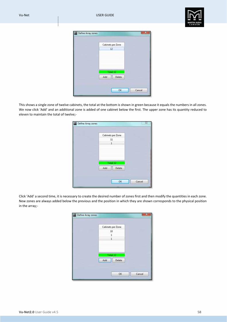
This shows a single zone of twelve cabinets, the total at the bottom is shown in green because it equals the numbers in all zones.
We now click ‘Add’ and an additional zone is added of one cabinet below the first. The upper zone has its quantity reduced to
eleven to maintain the total of twelve;‐
Click ‘Add’ a second time, it is necessary to create the desired number of zones first and then modify the quantities in each zone.
New zones are always added below the previous and the position in which they are shown corresponds to the physical position
in the array;‐
Vu‐Net USER GUIDE
Vu‐Net2.0 User Guide v4.5 59
…………
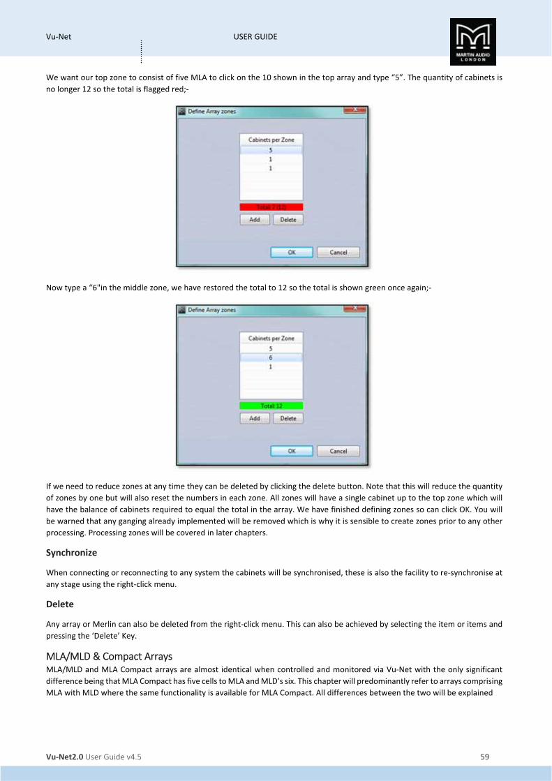
We want our top zone to consist of five MLA to click on the 10 shown in the top array and type “5”. The quantity of cabinets is
no longer 12 so the total is flagged red;‐
Now type a “6"in the middle zone, we have restored the total to 12 so the total is shown green once again;‐
If we need to reduce zones at any time they can be deleted by clicking the delete button. Note that this will reduce the quantity
of zones by one but will also reset the numbers in each zone. All zones will have a single cabinet up to the top zone which will
have the balance of cabinets required to equal the total in the array. We have finished defining zones so can click OK. You will
be warned that any ganging already implemented will be removed which is why it is sensible to create zones prior to any other
processing. Processing zones will be covered in later chapters.
Synchronize
When connecting or reconnecting to any system the cabinets will be synchronised, these is also the facility to re‐synchronise at
any stage using the right‐click menu.
Delete
Any array or Merlin can also be deleted from the right‐click menu. This can also be achieved by selecting the item or items and
pressing the ‘Delete’ Key.
MLA/MLD & Compact Arrays MLA/MLD and MLA Compact arrays are almost identical when controlled and monitored via Vu‐Net with the only significant
difference being that MLA Compact has five cells to MLA and MLD’s six. This chapter will predominantly refer to arrays comprising
MLA with MLD where the same functionality is available for MLA Compact. All differences between the two will be explained

Vu‐Net USER GUIDE
Vu‐Net2.0 User Guide v4.5 60
…………
Double clicking on an MLA/MLD or Compact array or right clicking and selecting ‘Open’ will open a new window as an additional
tab as shown;‐
MLA compact arrays will appear almost identically, just under the MLA logo the name is “MLAC" and of course there are only
five cells visible in the array thumbnail
This page is the Array Overview; each array also has a tab for Zone PEQ and Ganging. First we will look at the metering and gain
faders. Here is a 12 box array that has been divided into three zones, the top eight cabinets, next three and an MLD. The Master
and Zone Section looks like this;‐

Vu‐Net USER GUIDE
Vu‐Net2.0 User Guide v4.5 61
…………
The Master Gain allows up to +15dB of gain or 40dB attenuation of the input level to the entire array, the meter shows the
absolute level to the input stage of the cabinets, it is pre‐fader so if the level is clipping it is an indication that you need to
attenuate the signal upstream of the array, at the mixing console for example. The Master level as with the zone faders can be
adjusted in four ways, either dragging and dropping the fader knob to the required level, clicking just above or below the fader
knob which will increment or decrease the gain in steps specified in Preferences, clicking on the up/down arrows by the value
window or by typing a specific gain into the box at the bottom of the fader. A value between 15 and ‐40 can be entered, is a
value higher than 15 is typed, it will default to 15dB, if a value lower than ‐40 is typed it will default to ‐40.
Note that that the available gain and attenuation is combined for both the Master and Zone controls, for example if the Master
is boosted by 15dB you will not be able to boost any Zones. If the Master is boosted by say 5dB you will have up to 10dB of boost
available for the zones. If you attenuate the Master by say ‐30dB you will only have ‐10dB of attenuation for the zones and so
on.
At the bottom of the Master fader is a Mute button which will mute the entire array. The button and all zone mutes will turn red
when activated.
Next are the Zone faders which allow gain trim and mute for each of the zones that have been configured, in the example above
there are three. The maximum number is six. Gain may be adjusted exactly as described for the Master fader, dragging the fader
knob or typing a value. All zones may be adjusted completely independently. The zones also have a Mute button which will
instantly mute a zone. A further click will un‐mute the zone.
All zone mute buttons will also turn red to show they are all muted;‐
The Mute buttons can be freely changed whilst in normal mode, during set‐up for example but when in Show Mode you will be
prompted to confirm a mute function to avoid accidentally muting something while a show is in progress. See the Show Mode
chapter for more details.
The zone metering is post PEQ, each zone can be equalised independently so the metering will show the effect this has had in
addition to the effect that any gain trim has contributed. The zone meters differ from the Master in that they display headroom
rather than absolute level. 0dB at the top of the scale indicates clipping the signal level reached will show how much headroom
is available before clip.

Vu‐Net USER GUIDE
Vu‐Net2.0 User Guide v4.5 62
…………
The entire array is shown as a thumbnail diagram with each cell shown on every enclosure, on the left is an MLA/MLD array, on
the right is MLA Compact, both have been zoned in the same way;‐
The enclosures are grouped in their zones which are labelled on the left. The type of cabinet is shown on the left under the
Martin Audio logo, the MLD is also a slightly different greenish colour. The cells in each enclosure are labelled next to their
meters. The metering is post PEQ and pre amplifier and indicates level prior to limit. The yellow 0dB segment indicates that the
limit threshold has been met, the Red LEDs illuminating show progressive amounts of gain reduction in each limiter.
In the right corner of each element you will see the temperature readout‐
This displays two readings simultaneously, the top reading is the amplifier module that is showing the highest temperature, the
number on the left shows which module, in the example above it is number three which is the final two HF cells. The bottom
reading is the temperature of the DSP section.
Just above the temperature read‐out is a display showing the input setting for each individual cabinet. Here we can see a cabinet
set to AES Digital and one set to Analogue;‐

Vu‐Net USER GUIDE
Vu‐Net2.0 User Guide v4.5 63
…………
This will display the last input setting used with each cabinet so you can see at a glance if you have a miss‐match of input modes.
When uploading EQ optimisations together with a house PEQ file all inputs are reset to analogue. Alternatively you can change
the input mode manually and all cabinets will match, if for example you are running the system with an analogue feed and have
one cabinet showing AES, select AES from the input selection (see below) then select analogue to change all cabinets back to
analogue inputs. This indication is particularly useful if you have had to change a cabinet or amplifier module after loading
optimisations, whilst you will need to reload the optimisation at some point, it is reassuring to be able to rapidly check the input
mode if you hear any particularly strange sounds; a mix of analogue and AES inputs can sound extremely unpleasant.
Just below the zone level and metering is LED control if you need to identify a cabinet or cabinets again once you have completed
Device Discovery;‐
Pressing the ‘play’ triangle will start the LED running sequence from top cabinet to bottom. The play button then changes to a
pause and the ‘Next’ and ‘Previous’ buttons are greyed out;‐
Clicking the pause button will freeze the LED badge, the ‘previous’ and ‘next’ buttons can then be used to scroll the illuminated
LED badge between the cabinets. Clicking the square ‘Stop’ button will extinguish the LEDs.
Below the LED buttons you will find the Delay section which will add a delay to every cabinet. The delay displayed will be that
which was already residing in the array DSP when the devices were discovered and synchronised;‐
The delay can be entered in two ways, either by scrolling up and down using the up/down button on the right of the value box.
The increments are determined by the options in the Preferences menu, either 1.0, 0.5, 0.25, 0.2 or 0.1 milliseconds. Values can
also be directly typed into the box. The maximum value is 1,000.00ms (1 second).
Next to the delay is displayed the currently active snapshot;‐
In this case the factory default snapshot A. This display will automatically update when a new snapshot is loaded.
The final section on the System overview is the Input selection;‐
This is divided into three sections, the first selects the source from either the rear panel XLR input or via U‐Net;‐

Vu‐Net USER GUIDE
Vu‐Net2.0 User Guide v4.5 64
…………
Note that digital audio over U‐Net is not yet supported so this option should NOT be selected. When this option is active, the
second section is used to select the Unet source from one of the Merlins discovered on the network;‐
Once you have selected a Merlin, the final box gives you the choice of which channel from which to route the input to the array;‐
However, as mentioned, until notified otherwise, ALWAYS keep ‘Back Panel’ selected. The second panel will display ‘No Device’
and will be greyed out, the third panel will allow selection of either Analogue (the default selection) or AES3 Digital;‐
As AES feeds two interleaved digital channels you have the option to select either AES L or AES R. The initial display will match
what the array was set to when the system synchronised until you use the Preset Loader and load one of the default PEQ’s which
will set the input to Analogue. See the chapter of Preset Loading for more detail.
Array Cell Check
Double clicking on the array diagram brings up a new diagnostics screen which enables testing of individual cells, an extremely
useful tool for checking an array over either just before it is flown or back in the shop when a system is checked over. Note that
this function is not available when in Show Mode;‐

Vu‐Net USER GUIDE
Vu‐Net2.0 User Guide v4.5 65
…………
This is how the window appears, the array diagram is still visible on the right but it is now also shown on the left with each cell
shown but with a representation of its physical location in the cabinet;‐
Each cell can be muted from this section, this can be done by individual cells or the entire cabinet depending on the selection
mode selected;‐
In ‘MODULES’ mode clicking on any cell will mute or unmute all calls in the cabinet. In ‘CELLS’ mode you can mute and unmute
individual cells by clicking on them;‐

Vu‐Net USER GUIDE
Vu‐Net2.0 User Guide v4.5 66
…………
Or an entire cabinet can be muted by clicking on the button to the right of each enclosure regardless of which mode you have
selected;‐
This is how an entire muted enclosure is shown;‐
Pressing the Mute Array button;‐
Will mute every cell in the array;‐
Next to the Mute button is a play arrow;‐

Vu‐Net USER GUIDE
Vu‐Net2.0 User Guide v4.5 67
…………
This will cycle through either each cell or each module (all six cells) selected using the Selection Mode buttons;‐
IT will un‐mute whoever is selected sequentially so that any audio such as pink noise can be heard through just that section of
the array. If the entire array is un‐muted when the play button is clicked it will mute the array before starting its sequence.
Below the play button is a check box labelled "LED's ON' which will illuminate each cabinet's front grille badge LED while the cells
or entire module on that particular cabinet are un‐muted to make is visibly obvious which cabinet you are hearing‐ something
not always particularly easy if an array is 50m or more away from you.
There is an additional play arrow for each individual enclosure should you just wish to test a single cabinet.
It is good practice if you intend to use this test, to recall the default snapshot 'A' first. Without doing this all cells will have the
last parameters used still loaded so the sound from each cell when heard individually will vary enormously making it difficult to
judge if they are operating correctly.
When you have checked all cells, click on the “play" arrow a second time to stop the mute cycle. This is a very quick and easy
test for the system; it can be completed in the shop or on an array that has just been rigged prior to flying the system into place.
The big advantage is that there is no need to wait until front of house has been set up or any other part of the system, each array
can be tested individually the only additional equipment that is required is a simple signal generator which can even be an app
on a smart phone.
When the system has been tested and the signal source disconnected or switched off the system can be un‐muted by a further
click on the MUTE ARRAY button.
In addition to muting cells, you can also completely disable a cabinet by switching off the amplifier. This is designed for emergency
situations if for example an amplifier module has a fault and is generating unwanted noise. If you have tried the mute function
and the noise persists it is being generated by the amplifier not anything upstream in the audio path such as the DSP. In that
instance the only option is to switch off the amplifier. The mains distribution system has a breaker on each pair of cabinets so if
that were to be used to isolate a cabinet you would also unnecessarily switch off its neighbour so the mute output stage function
allows independent isolation of a single cabinet without disrupting any other functions. The big advantage of this compared to
physically powering off the entire cabinet is that the input and network sections are still powered as normal so no other functions
are disturbed, the U‐Net array and network will still appear functioning as normal just with the indication that the cabinet
amplifiers are off. To use the function first click in the Mute Output Stage box in the top left of the window;‐
Now click on either the thumbnail or the Mute all channels button of any cabinets which need to be isolated. All cells will appear
muted and on the array view you will see AMP OFF appear above the temperature table;‐

Vu‐Net USER GUIDE
Vu‐Net2.0 User Guide v4.5 68
…………
Note that the Mute Output stage box must remain checked; if it is unchecked the cabinets will revert to the standard mute
function and the AMPS OFF flags will disappear.
Also on the test page is the array noise gate control;‐
Each amplifier module has an internal noise gate set to keep the amplifier and DSP noise floor as inaudible as possible. By default
it is enabled but it is possible that with very low levels of program material the gate operation may be audible and so the gate
can be defeated by pressing the ENABLED button. The button will then display ‘DISABLED’;‐

Vu‐Net USER GUIDE
Vu‐Net2.0 User Guide v4.5 69
…………
The threshold, depth and hold time have been carefully calculated to give the best balance between making the operation as
inaudible as possible and maintaining a silent system but the parameters may be modified by either directly typing a value or by
scrolling up or down using the arrows to the side of the value windows. The Threshold can be any value from +20 to ‐120dB, the
depth from 0 to 120dB and the Hold time can range from 0 to 5,000 milliseconds. Default values are threshold of ‐84, Depth 10
and Hold time of 5000 for MLA and MLD and ‐67, 10 and 5000 for MLA Compact. These can be restored at any time by clicking
the Restore Defaults button.
To return to the main window click on the HIDE button in the bottom left;‐
If you have any muted output channels (muted not disabled), you will see the following window;‐
This ensures that you do not suddenly unmute all output channels while you have a test signal applied; pink noise at full volume
through an entire array is not something you want to suddenly subject a venue to. If you click OK you will return to the main
window and all output channels will be un‐muted. If you have disabled cabinets they will show AMPS OFF in the array
thumbnails;‐
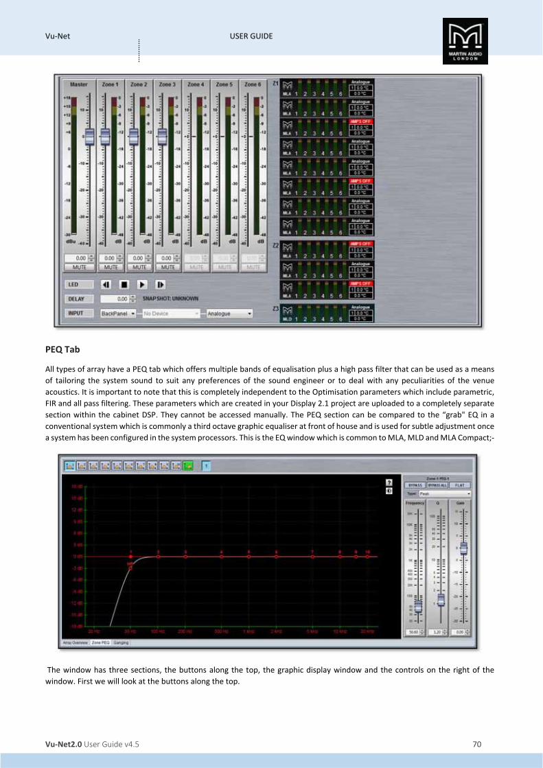
Vu‐Net USER GUIDE
Vu‐Net2.0 User Guide v4.5 70
…………
PEQ Tab
All types of array have a PEQ tab which offers multiple bands of equalisation plus a high pass filter that can be used as a means
of tailoring the system sound to suit any preferences of the sound engineer or to deal with any peculiarities of the venue
acoustics. It is important to note that this is completely independent to the Optimisation parameters which include parametric,
FIR and all pass filtering. These parameters which are created in your Display 2.1 project are uploaded to a completely separate
section within the cabinet DSP. They cannot be accessed manually. The PEQ section can be compared to the “grab" EQ in a
conventional system which is commonly a third octave graphic equaliser at front of house and is used for subtle adjustment once
a system has been configured in the system processors. This is the EQ window which is common to MLA, MLD and MLA Compact;‐
The window has three sections, the buttons along the top, the graphic display window and the controls on the right of the
window. First we will look at the buttons along the top.

Vu‐Net USER GUIDE
Vu‐Net2.0 User Guide v4.5 71
…………
First there are ten parametric EQ buttons plus the high pass filter;‐
As you can see there are a number of colour variations for these buttons. Unused bands are pale blue until they are selected for
editing by clicking on them in which case the colour goes to a brighter blue and the image shows the button depressed. Unused
is defined as the gain left at 0dB. A red button indicates that the band has been bypassed, irrespective of whether any gain
change has been made. Bypassed bands will change to a pale red when selected. Green buttons indicate a band that has either
cut or boost applied, these will go a pale green when selected. Note that the high pass filter is always active so will always appear
green.
Next there are the zone buttons;‐
In this example the array has three zones with zone 1 selected. As well as individual gain as already discussed, zones each have
completely independent PEQ to allow precise adjustment, most commonly used with the MLD which often requires a different
equalisation to the rest of the array. Clicking on the zone number brings up the PEQ page for that zone. If the array has not been
divided into zones there will just be one button with a number 1, essentially the entire array is a single zone.
The graphic view of the equalisation is a relatively standard frequency response graph;‐
The horizontal axis is frequency in Hertz from 20Hz to 20KHz, the vertical axis is gain from ‐18dB up to +18dB. Colour coding is
also used on the graph to represent the various modes.
First there are two traces, one red, and the other white. The red trace is the response of the band that is currently selected; the
white trace is the overall response of the entire PEQ.
Each small red circle represents the position of each of the ten bands plus the high pass. For all of the EQ bands the position on
the horizontal represents the EQ centre frequency, the vertical position is the cut or boost applied. A solid red circle is the
currently selected band, any greyed‐out band indicates that an EQ has been bypassed. The circle labelled "HP" identifies the cut‐
off frequency of the highpass filter.

Vu‐Net USER GUIDE
Vu‐Net2.0 User Guide v4.5 72
…………
In the right corner is this icon;‐
This is used to cycle between standard and daylight modes. In daylight mode the display changes to look like this;‐
This is intended for use outdoors setting up a festival system where the normal display is difficult to view in bright sunlight. A
further click on the icon will return to the default view.
In common with most PC controlled equalisation systems it is possible to make adjustments by dragging and dropping the filter
curves. Left‐click on any of the band rectangles and holding down the left mouse button, drag the icon horizontally to change
the centre frequency or vertically to change the gain. Either Right‐click and drag up and down or press Ctrl and drag up and down
to adjust the filter Q factor. You can also use the left and right keyboard buttons to adjust the selected band frequency, up/down
buttons to adjust gain and Page Up and Page down buttons which will adjust the Q factor. The graph will adjust and the audio
adjustment will be made in real time.
If at any stage you need a reminder of how to control the PEQ, right click on the question mark icon at the top of the graph;‐
This will bring up the following window;‐

Vu‐Net USER GUIDE
Vu‐Net2.0 User Guide v4.5 73
…………
There are also other functions available by right‐clicking elsewhere in the graph window whilst the cursor is over one of the
filters. This is the window that appears;‐
First is a copy all function which will copy Gain, Frequency and Q, of the selected band. You can also copy Frequency, Gain or Q
individually, you can then select a different band on the same or another graph (on a different zone or even different array) and
paste whichever parameters have been copied. The paste option will paste whoever parameter or parameters have been copied
onto the new filter that you have selected
The final section on the right of the window is the Properties panel;‐

Vu‐Net USER GUIDE
Vu‐Net2.0 User Guide v4.5 74
…………
This shows all properties of the selected band. At the top you will see some text indicating which zone and which band the
properties apply to. Below this are three buttons;‐
BYPASS bypasses the individual band you have selected turning the BYPASS button and the filter button red. BYPASS ALL bypasses
every band. FLAT will instantly change the gain to 0dB.
Next is a Filter type. Click on this and the drop down shows the options for each filter band;‐
The default is ‘Peak’, a standard parametric EQ; the other options are 2nd order Low Shelf and 2nd order High Shelf.
Below are the three principal faders for adjusting the filter parameters;‐

Vu‐Net USER GUIDE
Vu‐Net2.0 User Guide v4.5 75
…………
Parameters can be changed on the properties panel in three ways. The faders can be drag and dropped to a new value, the value
can be scrolled up or down using the up/down buttons to the right of the value windows, and finally values can be directly typed
into the value windows. The response graph will adjust according to the new values and vice versa, adjustments in the graph
window will be reflected in the fader positions and values in the properties panel.
The High pass filter only has a single fader for the corner frequency. This may be adjusted in exactly the same way as the faders
for the PEQ’s. The ‘Type’ drop down offers three types of filter and slopes from 6dB up to 48dB per octave;‐

Vu‐Net USER GUIDE
Vu‐Net2.0 User Guide v4.5 76
…………
To summarise, there are FIVE ways to adjust filter parameters;‐
1. Click and drag on the graph
2. Use the arrow and page up & down buttons
3. Click and drag the properties faders
4. Use the up/down value buttons
5. Directly type values into the value boxes.
Whilst this might seem over‐versatility, it is intended to offer several options to suit the way that the system is being operated.
If adjustments are being made with a tablet PC in tablet mode with a stylus whilst walking around a venue, certain options may
be easier to use than if you were sitting at a desk with a mouse plugged in to the PC.
Array & Zone Ganging
MLA Systems have a highly versatile set of ganging options to help make system set‐up consistent across arrays or zones. This is
the ganging page for a project consisting of two main MLA Arrays each of 12 enclosures and divided into three zones, plus two
side hangs each of 7 MLA plus 1 MLD. This is how the Array/Zone Ganging tab appears;‐
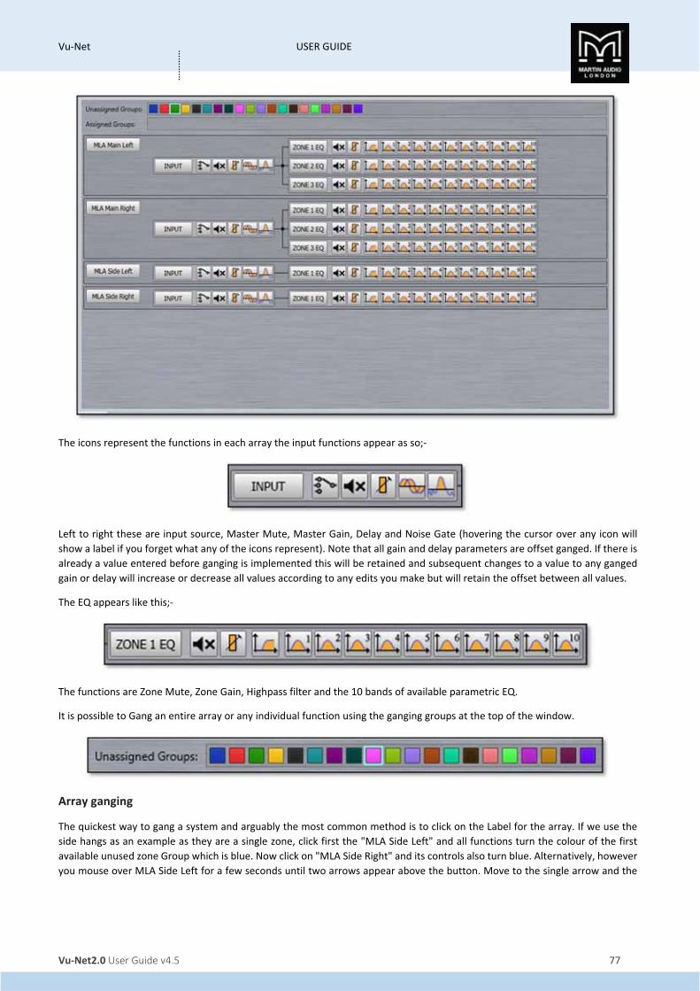
Vu‐Net USER GUIDE
Vu‐Net2.0 User Guide v4.5 77
…………
The icons represent the functions in each array the input functions appear as so;‐
Left to right these are input source, Master Mute, Master Gain, Delay and Noise Gate (hovering the cursor over any icon will
show a label if you forget what any of the icons represent). Note that all gain and delay parameters are offset ganged. If there is
already a value entered before ganging is implemented this will be retained and subsequent changes to a value to any ganged
gain or delay will increase or decrease all values according to any edits you make but will retain the offset between all values.
The EQ appears like this;‐
The functions are Zone Mute, Zone Gain, Highpass filter and the 10 bands of available parametric EQ.
It is possible to Gang an entire array or any individual function using the ganging groups at the top of the window.
Array ganging
The quickest way to gang a system and arguably the most common method is to click on the Label for the array. If we use the
side hangs as an example as they are a single zone, click first the "MLA Side Left" and all functions turn the colour of the first
available unused zone Group which is blue. Now click on "MLA Side Right" and its controls also turn blue. Alternatively, however
you mouse over MLA Side Left for a few seconds until two arrows appear above the button. Move to the single arrow and the

Vu‐Net USER GUIDE
Vu‐Net2.0 User Guide v4.5 78
…………
message "Apply to below items within the array/device". This is the same functions as clicking on the button. Move over to the
double arrow and the text "Apply to ALL items below" appears.
Click on the double arrow and both arrays will be ganged. This option will gang all of the same function on arrays below the
button;‐
Note that input source selection is not automatically ganged either by using the Array name or the Input group, these must
always be selected individually to join a gang.
If we do the same with the main Left and right arrays they will also be ganged but as the arrays have been zoned into three,
each zone is ganged individually zone groups being assigned in order of their availability;‐

Vu‐Net USER GUIDE
Vu‐Net2.0 User Guide v4.5 79
…………
You can see that zone 1 is red, zone 2 green and zone 3 yellow. Any EQ changes made on any zone will be duplicated in the zone
on the other array.
It is also possible to zone just the array input functions, just the array EQ or individual parameters. In this example we just
required the side hang EQ to be ganged leaving the input functions available for independent adjustment. First we selected an
available Group, in this case pink, then clicked on "Zone 1 EQ" on both Side arrays;‐
If we wanted to add the gain and delay to this gang simply click on those icons either individually or using the double arrow;‐

Vu‐Net USER GUIDE
Vu‐Net2.0 User Guide v4.5 80
…………
Perhaps a more practical example is to gang the entire array and just de‐select any parameters that we do not wish to gang, here
we will gang both Main left and right together, both Side hangs but then click on the mute icon so we can mute and unmute each
array independently of each other;‐
To un‐gang any individual parameter, input parameter group, EQ group or entire array just click a second time and the ganging
is removed.
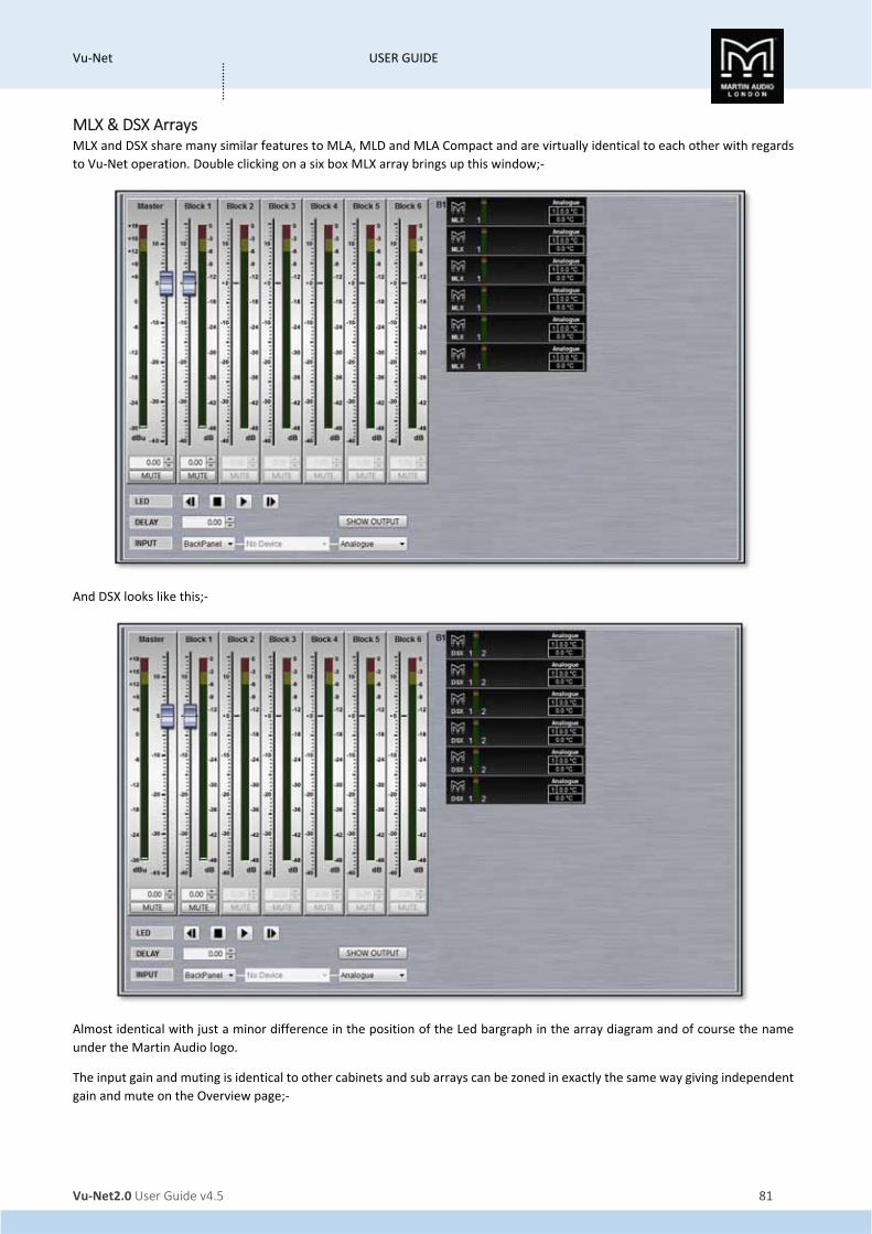
Vu‐Net USER GUIDE
Vu‐Net2.0 User Guide v4.5 81
…………
MLX & DSX Arrays MLX and DSX share many similar features to MLA, MLD and MLA Compact and are virtually identical to each other with regards
to Vu‐Net operation. Double clicking on a six box MLX array brings up this window;‐
And DSX looks like this;‐
Almost identical with just a minor difference in the position of the Led bargraph in the array diagram and of course the name
under the Martin Audio logo.
The input gain and muting is identical to other cabinets and sub arrays can be zoned in exactly the same way giving independent
gain and mute on the Overview page;‐

Vu‐Net USER GUIDE
Vu‐Net2.0 User Guide v4.5 82
…………
Sub arrays when zoned are referred to as ‘blocks’ rather than zones.
The array thumbnail is almost identical to the MLA/MLD and MLA Compact just with a single LED level meter to reflect the single
cell. The temperature readout will always show ‘1’ and display the temperature of the single amplifier channel on the top line
and the DSP on the lower line. Input mode is also displayed above the temperature read‐out. If the array has been zoned the
zones or “blocks" are numbered from top to bottom;‐
Both subs have exactly the same LED, Array Mute, delay and input routing as for MLA, MLD and MLA Compact;‐

Vu‐Net USER GUIDE
Vu‐Net2.0 User Guide v4.5 83
…………
There is however the significant difference of there being no snapshot name as subs do not have snapshot capability and there
is an additional button “SHOW OUTPUT" which replaces the double click on the other products to bring up additional features;‐
Clicking this button brings up the following window on both MLX and DSX;‐
This allows individual control of gain, phase, polarity and mute for each sub in the array. Most often used when creating cardioid
arrays with a third of the subs rear facing and requiring independent control of the rear facing subs to the front. The LED button
gives you the option to flash the LED of each sub to ensure that you are applying parameters to the correct cabinet. The gain
allows independent adjustment of the gain of each sub and is automatically adjusted to match the gain structure of the system
determined by the SPL reference set in the Display 2.2 optimisation, see the chapter on Preset loading for more details. If at any
stage you wish to reset the parameters, perhaps immediately after device discovery where the subs may still be displaying values
from their previous use, you can click on the ‘Reset Outputs’ button;‐
A warning window will appear;‐
If you click on OK, all gain and delays will be restored to zero, any inverted outputs will be re‐inverted and any muted outputs
will be un‐muted.

Vu‐Net USER GUIDE
Vu‐Net2.0 User Guide v4.5 84
…………
Subs also have the facility to turn off any troublesome amplifiers by checking the ‘Mute Output Stage’ box;‐
Then clicking the Mute button on any sub you wish to turn off.
As with other cabinets there is a noise gate which has the Threshold and Hold Time available for modification. The Default values
can be restored at any time by using the Restore Defaults button;‐
Both MSX and DSX have default values as shown above of a threshold of ‐84dB, a Depth of 100dB and a hold time of 5000ms.
When you have finished setting output parameters you can close the output window with a further click on the SHOW OUTPUT
button. Any amplifiers that have been switched off will have the AMPS OFF indication above the temperature read‐out;‐
Block PEQ
Equalisation in the subs is referred to as ‘Block PEQ’ on the tab. It is almost identical to the EQ page for the MLA, MLD and MLA
Compact with a low pass filter replacing the high pass as you might expect;‐

Vu‐Net USER GUIDE
Vu‐Net2.0 User Guide v4.5 85
…………
There are also ten PEQ filters at your disposal, each with exactly the same functionality and control. The low pass filter in
common with the high‐pass in the MLA, MLD and Compact, can be either Bessel, Butterworth or Linkwitz Riley with slopes from
6dB per octave up to 48dB per octave. The frequency can range from 50Hz up to 500Hz;‐
Sub Array/Block Ganging
Sub arrays can be ganged in virtually identical fashion to MLA, MLD and Compact, either by entire array, Input parameters, Zones
(blocks), or individual Parameters.

Vu‐Net USER GUIDE
Vu‐Net2.0 User Guide v4.5 86
…………
Ganging can be very useful for Cardioid arrays but it is important to remember that individual delays, mute and polarity are NOT
ganged; they must be individually modified in the array output page. Note that all gain and delay parameters are offset ganged.
If there is already a value entered before ganging is implemented this will be retained and subsequent changes to a value to any
ganged gain or delay will increase or decrease all values according to any edits you make but will retain the offset between all
values.

Vu‐Net USER GUIDE
Vu‐Net2.0 User Guide v4.5 87
…………
MLA Mini MLA Mini retains many of the network features of its bigger brothers but with a slightly different approach to the implementation
within Vu‐Net. Double clicking on an array (regardless of how the system has been deployed), brings up the following Window;‐
As you can see, the main array window is almost identical to the other MLA System components; there are the usual six zones
available each with a gain fader and mute switch. As with other systems, unassigned zones do not have a fader and the gain
read‐out and mute switch are greyed out. If you attempt to adjust gain or mute an un‐assigned zone you will see the following
window;‐
There is the same LED badge option, up to 1,000ms of delay and a similar input select from either the back panel or U‐Net (not
presently implemented) and back panel input can be either Analogue, AES3 Left or AES3 right with the addition of an AES split
mode which routes AESL to the MSX and AESR to the MLA Mini;‐
In common with sub arrays there is a SHOW OUTPUT button to access array utility functions rather than double clicking on the
array thumbnail.
MLA Mini Cell check
As long as Show mode is not active, clicking on the SHOW OUTPUT button;‐

Vu‐Net USER GUIDE
Vu‐Net2.0 User Guide v4.5 88
…………
Brings up an array diagram with each cell individually accessible as with MLA and MLA Compact systems. Clicking on the MUTE
ARRAY button will mute every cell;‐
A test signal such as Pink Noise can be applied to the array and each cell can be individually un‐muted by clicking on it to test
that everything is operating correctly and all components are in the correct position in the array. This can be done by individual
cells if the Selection mode is in the ‘CELLS' position or by an entire MLX and 4 Mini group if you click on ‘MODULES’. This is
particularly important as the amplifier modules are all in the MSX sub, it is possible to incorrectly wire from the MSX to the MLA
Mini. You can either click on cells manually to unmute them and there is a “play" function to cycle through all cells in the array.
Unlike the other systems, unmuting a cell will mute all others which speeds up the testing process as you no longer need to
manually mute the last cell you listened to before un‐muting the next.
As with the other cabinets, the array noise gate is accessible but in MLA Mini there is only the option to Enable or Disable the
gate;‐
When you have completed any testing, click on the HIDE button;‐
Which will un‐mute all cells and return you to the main array window.
Assigning Zones in MLA Mini

Vu‐Net USER GUIDE
Vu‐Net2.0 User Guide v4.5 89
…………
As with MLA, MLD and MLA Compact, there are up to six zones available for the system as the Array Overview shows. How these
are defined is however different from the other MLA components. You may have noticed that the right‐click function in the
System diagram does not allow zone definition for an MLA Mini Array. Instead, zones are defined using the zone faders. If you
look at the Array Overview thumbnail, you will notice that the MSX (two in our example) have a red border and the 8 MLA Mini
have a blue border;‐
By default, MSX are assigned to zone 1 and all MLA Mini to zone 2. Reassigning zones is extremely simple. In our example we will
keep the MSX assigned to zone 1, the top four MLA Mini to zone 2, the next two to zone 3 and the final two to zone 4. First click
on the Zone 1 label;‐
You will notice All components that are already part of the zone will turn red;‐
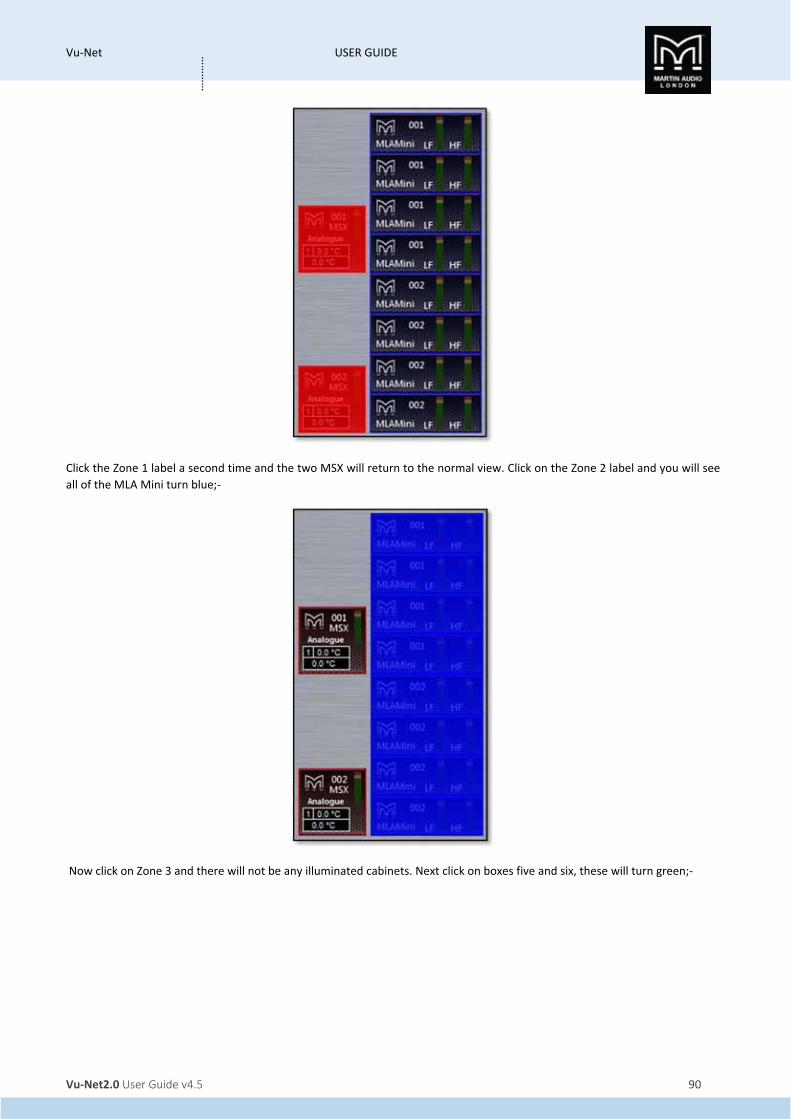
Vu‐Net USER GUIDE
Vu‐Net2.0 User Guide v4.5 90
…………
Click the Zone 1 label a second time and the two MSX will return to the normal view. Click on the Zone 2 label and you will see
all of the MLA Mini turn blue;‐
Now click on Zone 3 and there will not be any illuminated cabinets. Next click on boxes five and six, these will turn green;‐
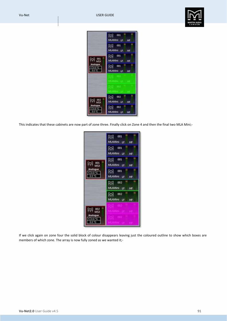
Vu‐Net USER GUIDE
Vu‐Net2.0 User Guide v4.5 91
…………
This indicates that these cabinets are now part of zone three. Finally click on Zone 4 and then the final two MLA Mini;‐
If we click again on zone four the solid block of colour disappears leaving just the coloured outline to show which boxes are
members of which zone. The array is now fully zoned as we wanted it;‐

Vu‐Net USER GUIDE
Vu‐Net2.0 User Guide v4.5 92
…………
MLA Mini PEQ
The MLA Mini Zone PEQ window appears like this;‐
It is a slightly simplified version of the PEQ Tab that is available in all other array components. The six available zones can be
selected by using the Zone buttons at the top of the window;‐
Zone 1 is always the MSX sub so the EQ bands available are slightly different. There is a high pass filter, low pass filter and three
bands of PEQ all of which may be adjusted in the same way as the PEQ in all other array types; grabbing the points on the graph,

Vu‐Net USER GUIDE
Vu‐Net2.0 User Guide v4.5 93
…………
adjusting the controls in the EQ panel on the right or directly entering the required values in the windows at the bottom of the
EQ panel.
Zones 2 to 6 all have a high pass filter and six bands of PEQ;‐
MLA Mini Ganging
Ganging for MLA Mini is handled in an identical way to all other devices. If you select the Array/Zone Ganging tab we see the
following view. Note that for this example we have a Vu‐Net project consisting of two main left and right arrays each with two
MSX and eight MLA Mini, plus two “side" arrays each with a single MSX and four Mini. The larger array has four zones; one for
MSX and three for the array, the side arrays have the default two zones;‐
In exactly the same way as other devices you can choose to gang the entire arrays, just the input parameters, the output
parameters by zone or individual parameters. Note that all gain and delay parameters are offset ganged. If there is already a

Vu‐Net USER GUIDE
Vu‐Net2.0 User Guide v4.5 94
…………
value entered before ganging is implemented this will be retained and subsequent changes to a value to any ganged gain or
delay will increase or decrease all values according to any edits you make but will retain the offset between all values.
There are the same 20 independent groups available for both types of ganging, selected by the coloured Group buttons along
the top of the window in the Unassigned Groups section
Array Ganging To gang an entire array, click on all arrays you wish to be ganged together. In our example we will gang the main left and right
arrays and on a second group the two side arrays. There is no need to select a group they will be assigned automatically with
different groups for each zone. You will need to select a different group to zone the side hangs;‐
If you wanted all four arrays zoned together you can use the double arrows that appear on any of the buttons when you hover
the cursor over them for over a second;‐
When you gang arrays which have different numbers of zones you will see this message;‐
Any of the individual parameters can be excluded from a ganged system simply by clicking on them. A typical example might be
to gang everything other than mute so you can ensure that arrays are matched left and right but have the ability to mute them
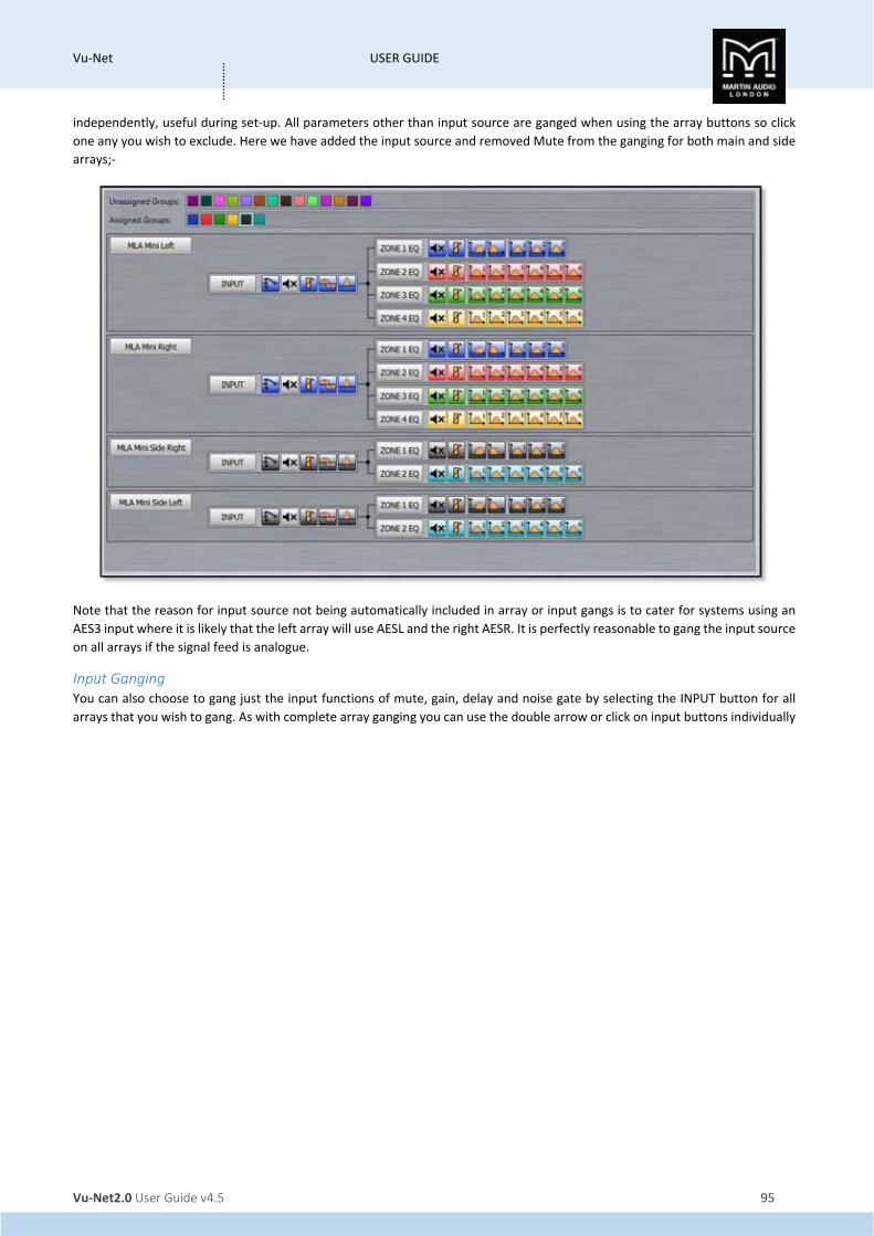
Vu‐Net USER GUIDE
Vu‐Net2.0 User Guide v4.5 95
…………
independently, useful during set‐up. All parameters other than input source are ganged when using the array buttons so click
one any you wish to exclude. Here we have added the input source and removed Mute from the ganging for both main and side
arrays;‐
Note that the reason for input source not being automatically included in array or input gangs is to cater for systems using an
AES3 input where it is likely that the left array will use AESL and the right AESR. It is perfectly reasonable to gang the input source
on all arrays if the signal feed is analogue.
Input Ganging You can also choose to gang just the input functions of mute, gain, delay and noise gate by selecting the INPUT button for all
arrays that you wish to gang. As with complete array ganging you can use the double arrow or click on input buttons individually
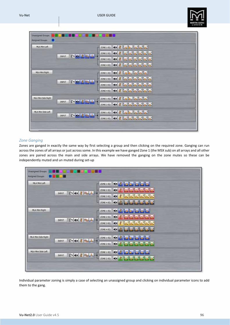
Vu‐Net USER GUIDE
Vu‐Net2.0 User Guide v4.5 96
…………
Zone Ganging Zones are ganged in exactly the same way by first selecting a group and then clicking on the required zone. Ganging can run
across the zones of all arrays or just across some. In this example we have ganged Zone 1 (the MSX sub) on all arrays and all other
zones are paired across the main and side arrays. We have removed the ganging on the zone mutes so these can be
independently muted and un muted during set‐up
Individual parameter zoning is simply a case of selecting an unassigned group and clicking on individual parameter icons to add
them to the gang.

Vu‐Net USER GUIDE
Vu‐Net2.0 User Guide v4.5 97
…………
DD12 DD12’s are discovered in exactly the same way as any other device regardless of whether they are connected via a full U‐Net
network to a Merlin or directly via USB. The Device discovery will show all connected cabinets;‐
As there are no array‐related options with the DD12 the ‘Run Wizard’ merely synchronises with all connected cabinets so the
software reflects the settings in the devices.
A system connected via USB will appear like this;‐
A system connected via Merlin like this;‐

Vu‐Net USER GUIDE
Vu‐Net2.0 User Guide v4.5 98
…………
Each DD12 icon in the overview screen features a Martin Audio logo. Double‐clicking on this will illuminate the LED on the cabinet
front grille to assist in identifying each DD12 which is very useful when multiple units are deployed.
There are a number of functions available by right clicking on a cabinet icon;‐
‘Open’ functions in exactly the same way as double clicking on the cabinet icon and opens the DD12 overview screen to allow
detailed control and monitoring
'Load Snapshot' brings up the snapshot window allowing you to select with one of the factory or User snapshots if any have been
created;‐

Vu‐Net USER GUIDE
Vu‐Net2.0 User Guide v4.5 99
…………
Click on the snapshot number to choose the snapshot you need, you will be prompted to confirm;‐
'Save Snapshot' allows you to store a configuration that you have created to one of the User Snapshot locations. There are 12
locations available;‐

Vu‐Net USER GUIDE
Vu‐Net2.0 User Guide v4.5 100
…………
Click on the Snapshot letter for the location you wish to use and you will be prompted to ass a snapshot name;‐
Type a name of up to 30 characters and the snapshot will be saved.
'Import Snapshot' allows you to recall a DD12 snapshot that has been exported to a file. Selecting Import brings up this window;‐
Click 'select' to navigate to the file location where you have stored DD12 Snapshot files. Next click on the target snapshot location
within the User Locations, note that the imported file will overwrite any existing snapshot so if you need to retain any of those
select a vacant location. Click 'Import' and the file will be imported and that snapshot immediately selected.
'Load in Background' allows you to load a file to a snapshot location of your choice and as long as you don't select the active
snapshot location the file will be uploaded without disturbing the settings, even if the cabinet is in use passing audio.
'Export Snapshot' is how you create the DD12 .sn files which can be imported at future events. The Export windows appears like
this;‐
You can elect to export the current settings giving the file an appropriate name, or one of the existing snapshots. Selecting this
option will allow you to select one of the stored snapshots from a drop‐down list. The drop‐down ignores any undefined snapshot
locations;‐

Vu‐Net USER GUIDE
Vu‐Net2.0 User Guide v4.5 101
…………
Click Select and navigate to a suitable location on your PC and give the file a suitable name, the file will automatically have a .sn
file extension generated. Click 'Export' and the file will be stored.
'Synchronise' is a manual synchronise that duplicates the automatic synchronise that occurs when a DD12 is discovered to ensure
that what is displayed in Vu‐Net matches exactly the parameters stored within the cabinet DSP.
'Disconnect/Reconnect' allows you to disconnect and individual cabinet which will turn red once disconnected;‐
Selecting the same function will reconnect the cabinet and it will revert to the standard appearance.
‘Rename’ as with any other device allows the cabinet to be given a name of up to 50 characters;‐
‘Select All’ selects all devices in the system Diagram, the keyboard shortcut for this is Ctrl + A.
‘Load Preset’ allows you to load one of the already stored Presets. The Preset window appears;‐
Click on the required preset and you will see a Window asking you to confirm your selection;‐

Vu‐Net USER GUIDE
Vu‐Net2.0 User Guide v4.5 102
…………
‘Delete’ removes the selected DD12. You will be prompted with the following Window to confirm the delete;‐
If you selected Delete accidentally or have changed your mind, click ‘Cancel’, otherwise click ‘OK' and the DD12 will be removed
from the project.
Overview
Either double clicking or right clicking and selecting Open will bring up the overview option for the DD12 which shows all DD12s
in the project;‐
This gives an overview of the state of all DD12’s allowing comprehensive monitoring of the system.
The box at the top will show any names that have been assigned to the cabinets by right clicking and selecting rename (or
selecting and pressing F2 in the System Diagram;‐

Vu‐Net USER GUIDE
Vu‐Net2.0 User Guide v4.5 103
…………
The gain fader allows gain adjustment from ‐40 to +15dB. Precise values can be entered by typing directly in the box below the
fader or values can be scrolled up or down using the up/down buttons. The increments that the up/down buttons will step is
determined in the Preferences section, by default it will be 0.25dB.
The mute button will mute the cabinet irrespective of the position of the gain fader and will turn red when active.
There is comprehensive metering available. The bargraph to the left of the fader shows input level up to the maximum before
input clip of +18dBu. The smaller meters to the right show the amplifier output levels for both the low frequency amplifier driving
the 12"driver and the high frequency amplifier driving the compression driver and show level prior to limit. If the levels reach
the yellow segment you have reached the limiter threshold. A red segment indicated 3dB of gain reduction in the limiter.
There is also a temperature read out showing the temperature of both the DSP and amplifier module;‐
There is delay available which is very useful for time aligning the DD12 when used as an extra fill with a larger mains system. The
maximum delay available is 1 second. Values can either be typed directly into the Delay field or scrolled up and down using the
arrow buttons. These increase or decrease the delay in increments of 10µs.
The Input allows the connection mode to be changed from the default which is Analogue to AES/EBU or Unet (not currently
available) taking its feed from either AES left or AES right. This can either be done individually for each DD12 or globally using
the Input switch at the bottom of the DD12 overview Window. A global change will bring up the flowing window;‐

Vu‐Net USER GUIDE
Vu‐Net2.0 User Guide v4.5 104
…………
Click ‘Cancel’ if you have changed your mind or ‘OK’ to accept the change of input mode. All DD12’s will display the new input
selection.
The Snapshot button gives access to either the loan or save snapshot functions available from the right‐click menu in the Project
System Diagram. Clicking on the button will bring up both options as shows;‐
Clicking LOAD will bring up the Snapshot Menu with the currently active Snapshot shown highlighted in green;‐
Clicking on a new Snapshot number or letter will prompt you to confirm your selection;‐

Vu‐Net USER GUIDE
Vu‐Net2.0 User Guide v4.5 105
…………
Clicking ‘OK’ will confirm the selection and the preset will load. The Preset select window can be closed. The currently active
Snapshot is displayed on the Snapshot button;‐
Clicking SAVE will bring up the Save snapshot menu in the same way as the right click option in the system overview page;‐
Polarity will invert the phase of the cabinet. If in Show Mode a confirmation window will appear;‐
On clicking ‘OK’ the phase will be inverted and the Polarity button will turn green;‐
Clicking the LED button will illuminate the front grille LED to help identify the DD12 under control in multiple deployment
applications. This can be done individually for any cabinet;‐

Vu‐Net USER GUIDE
Vu‐Net2.0 User Guide v4.5 106
…………
Or globally using the LED controls at the bottom of the DD12 Overview window;‐
Pressing the “play" arrow will make the LEDs of all DD12s illuminate in sequence, cycling round continually until you click on
the stop button Note that the global LED switches will overwrite any LEDs which have been activated on an individual DD12.
The back and forward buttons allow manual cycling of all cabinet LEDs, each click will extinguish the currently
illuminated LED and light the LED on the next or previous DD12.
EQ
The EQ button will open the EQ tab for that particular DD12. The EQ window is virtually identical to all other Vu‐Net controlled
devices;‐
The window has three sections, the buttons along the top, the graphic display window and the controls on the right of the
window. First we will look at the buttons along the top.
First there are ten parametric EQ buttons plus the high pass filter;‐
As you can see there are a number of colour variations for these buttons. Unused bands are pale blue until they are selected for
editing by clicking on them in which case the colour goes to a brighter blue and the image shows the button depressed. Unused
is defined as the gain left at 0dB. A red button indicates that the band has been bypassed, irrespective of whether any gain
change has been made. Bypassed bands will change to a pale red when selected. Green buttons indicate a band that has either
cut or boost applied, these will go a pale green when selected. Note that the high pass filter is always active so will always appear
green.
The graphic view of the equalisation is a relatively standard frequency response graph;‐

Vu‐Net USER GUIDE
Vu‐Net2.0 User Guide v4.5 107
…………
The horizontal axis is frequency in Hertz from 20Hz to 20KHz, the vertical axis is gain from ‐18dB up to +18dB. Colour coding is
also used on the graph to represent the various modes.
First there are two traces, one red, and the other white. The red trace is the response of the band that is currently selected; the
white trace is the overall response of the entire PEQ.
Each small red circle represents the position of each of the ten bands plus the high pass. For all of the EQ bands the position on
the horizontal represents the EQ centre frequency, the vertical position is the cut or boost applied. A solid red circle is the
currently selected band, any greyed‐out band indicates that an EQ has been bypassed. The circle labelled "HP" identifies the cut‐
off frequency of the highpass filter.
In the right corner is this icon;‐
This is used to cycle between standard and daylight modes. In daylight mode the display changes to look like this;‐

Vu‐Net USER GUIDE
Vu‐Net2.0 User Guide v4.5 108
…………
This is intended for use outdoors setting up a festival system where the normal display is difficult to view in bright sunlight. A
further click on the icon will return to the default view.
In common with most PC controlled equalisation systems it is possible to make adjustments by dragging and dropping the filter
curves. Left‐click on any of the band rectangles and holding down the left mouse button, drag the icon horizontally to change
the centre frequency or vertically to change the gain. Right‐click and drag or Ctrl and drag up and down to adjust the filter Q
factor. The graph will adjust and the audio adjustment will be made in real time.
The final section on the right of the window is the Properties panel;‐

Vu‐Net USER GUIDE
Vu‐Net2.0 User Guide v4.5 109
…………
This shows all properties of the selected band. At the top are three buttons;‐
‘BYPASS’ bypasses the individual band you have selected turning the BYPASS button and the filter button red. ‘BYPASS ALL’
bypasses every band. ‘FLAT’ will instantly change the gain to 0dB.
Next is a Filter type. Click on this and the drop down shows the options for each filter band;‐
The default is ‘Peak’, a standard parametric EQ; the other options are 2nd order Low Shelf and 2nd order High Shelf.
Below are the three principal faders for adjusting the filter parameters;‐
Parameters can be changed on the properties panel in three ways. The faders can be drag and dropped to a new value, the value
can be scrolled up or down using the up/down buttons to the right of the value windows, and finally values can be directly typed
into the value windows. The response graph will adjust according to the new values and vice versa, adjustments in the graph
window will be reflected in the fader positions and values in the properties panel.
The High pass filter only has a single fader for the corner frequency. This may be adjusted in exactly the same way as the faders
for the PEQ’s. The ‘Type’ drop down offers three types of filter and slopes from 12dB up to 48dB per octave;‐
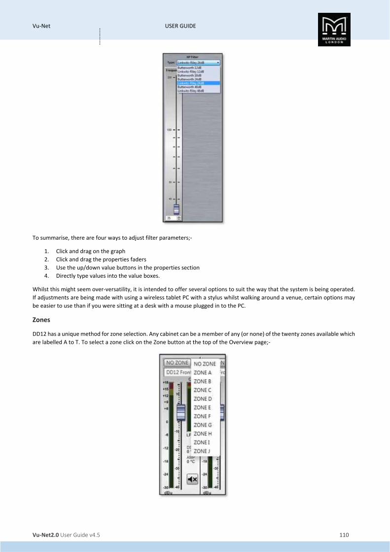
Vu‐Net USER GUIDE
Vu‐Net2.0 User Guide v4.5 110
…………
To summarise, there are four ways to adjust filter parameters;‐
1. Click and drag on the graph
2. Click and drag the properties faders
3. Use the up/down value buttons in the properties section
4. Directly type values into the value boxes.
Whilst this might seem over‐versatility, it is intended to offer several options to suit the way that the system is being operated.
If adjustments are being made with using a wireless tablet PC with a stylus whilst walking around a venue, certain options may
be easier to use than if you were sitting at a desk with a mouse plugged in to the PC.
Zones
DD12 has a unique method for zone selection. Any cabinet can be a member of any (or none) of the twenty zones available which
are labelled A to T. To select a zone click on the Zone button at the top of the Overview page;‐
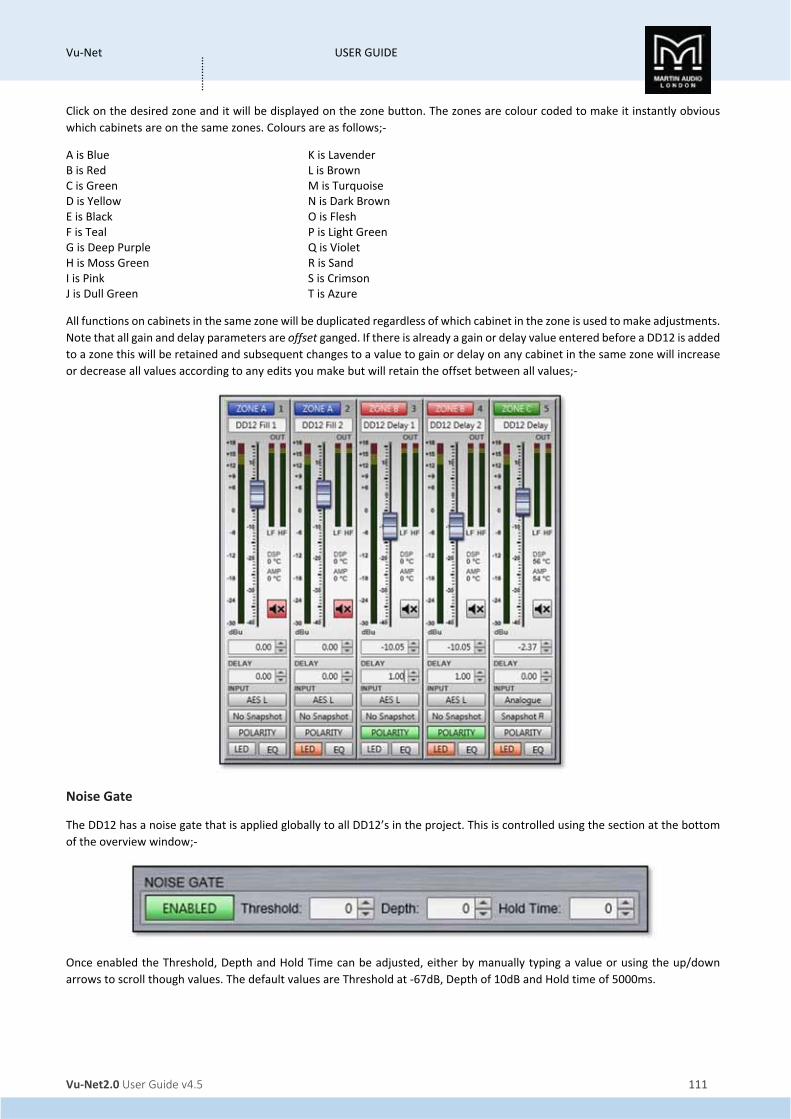
Vu‐Net USER GUIDE
Vu‐Net2.0 User Guide v4.5 111
…………
Click on the desired zone and it will be displayed on the zone button. The zones are colour coded to make it instantly obvious
which cabinets are on the same zones. Colours are as follows;‐
A is Blue K is Lavender B is Red L is Brown C is Green M is Turquoise D is Yellow N is Dark Brown E is Black O is Flesh F is Teal P is Light Green G is Deep Purple Q is Violet H is Moss Green R is Sand I is Pink S is Crimson J is Dull Green T is Azure
All functions on cabinets in the same zone will be duplicated regardless of which cabinet in the zone is used to make adjustments.
Note that all gain and delay parameters are offset ganged. If there is already a gain or delay value entered before a DD12 is added
to a zone this will be retained and subsequent changes to a value to gain or delay on any cabinet in the same zone will increase
or decrease all values according to any edits you make but will retain the offset between all values;‐
Noise Gate
The DD12 has a noise gate that is applied globally to all DD12’s in the project. This is controlled using the section at the bottom
of the overview window;‐
Once enabled the Threshold, Depth and Hold Time can be adjusted, either by manually typing a value or using the up/down
arrows to scroll though values. The default values are Threshold at ‐67dB, Depth of 10dB and Hold time of 5000ms.
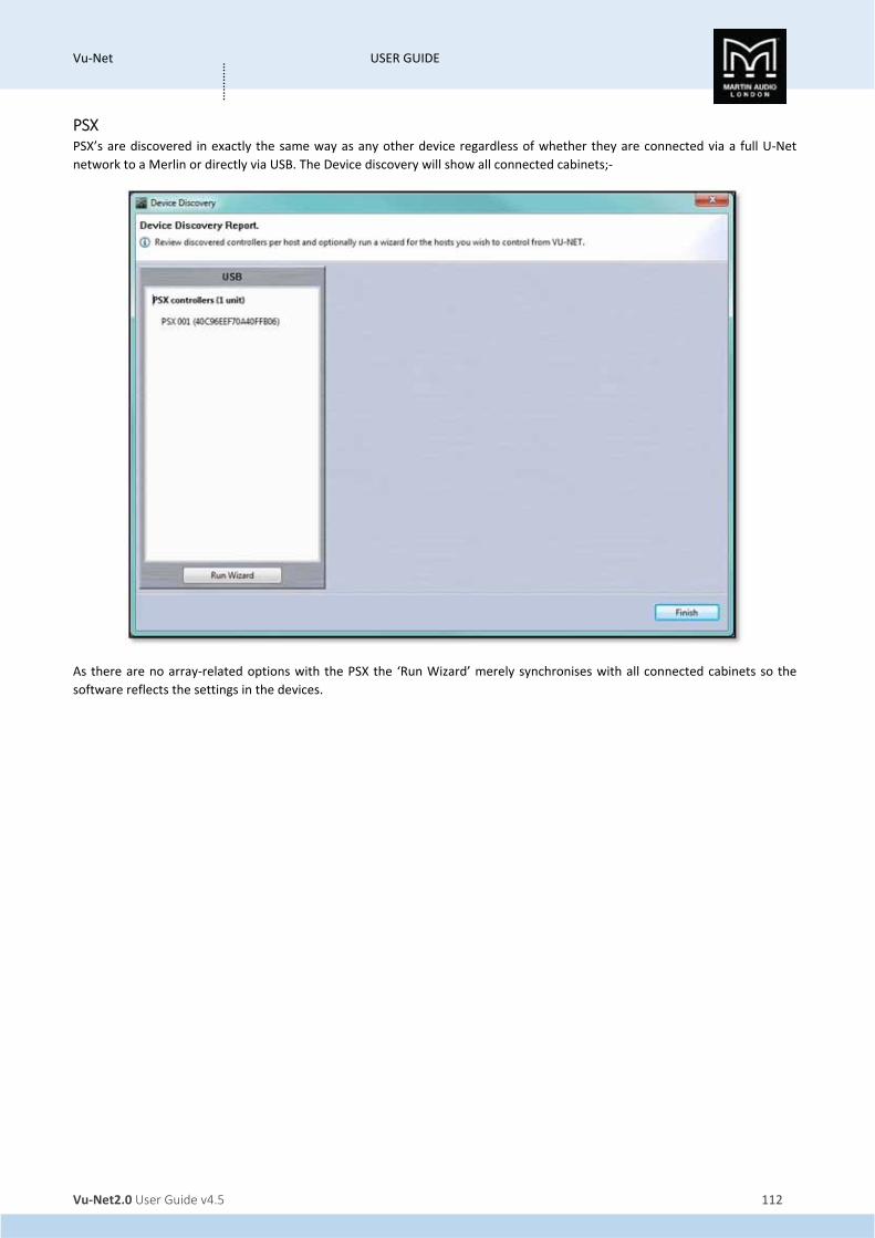
Vu‐Net USER GUIDE
Vu‐Net2.0 User Guide v4.5 112
…………
PSX PSX’s are discovered in exactly the same way as any other device regardless of whether they are connected via a full U‐Net
network to a Merlin or directly via USB. The Device discovery will show all connected cabinets;‐
As there are no array‐related options with the PSX the ‘Run Wizard’ merely synchronises with all connected cabinets so the
software reflects the settings in the devices.

Vu‐Net USER GUIDE
Vu‐Net2.0 User Guide v4.5 113
…………
A system connected via USB will appear like this;‐
Each PSX icon in the overview screen features a Martin Audio logo. Double‐clicking on this will illuminate the LED on the cabinet
front grille to assist in identifying each PSX which is very useful when multiple units are deployed.
There are a number of functions available by right clicking on a cabinet icon;‐

Vu‐Net USER GUIDE
Vu‐Net2.0 User Guide v4.5 114
…………
‘Open’ functions in exactly the same way as double clicking on the cabinet icon and opens the DD12 overview screen to allow
detailed control and monitoring
'Load Snapshot' brings up the snapshot window allowing you to select with one of the factory or User snapshots if any have been
created;‐
Click on the snapshot number to choose the snapshot you need, you will be prompted to confirm;‐

Vu‐Net USER GUIDE
Vu‐Net2.0 User Guide v4.5 115
…………
'Save Snapshot' allows you to store a configuration that you have created to one of the User Snapshot locations. There are 12
locations available;‐
Click on the Snapshot letter for the location you wish to use and you will be prompted to ass a snapshot name;‐
Type a name of up to 30 characters and the snapshot will be saved.
'Import Snapshot' allows you to recall a DD12 snapshot that has been exported to a file. Selecting Import brings up this window;‐
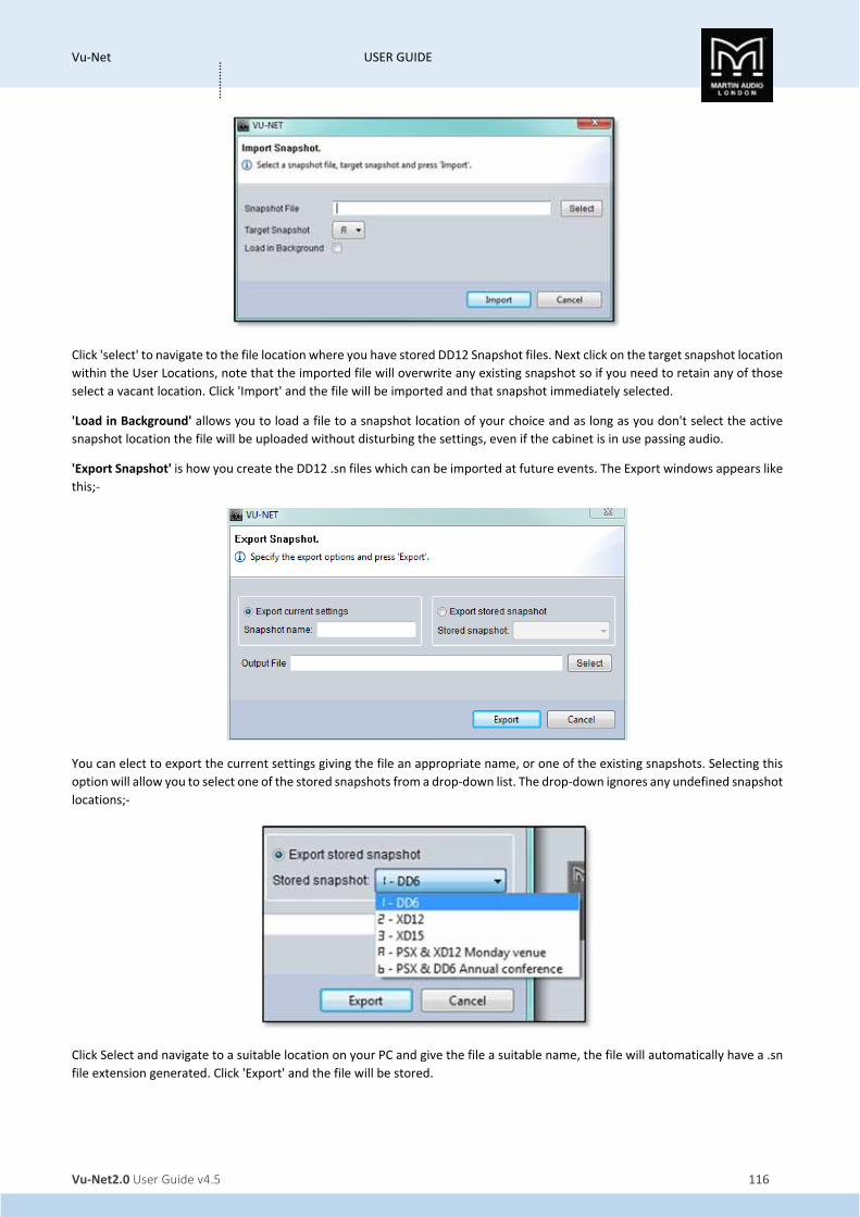
Vu‐Net USER GUIDE
Vu‐Net2.0 User Guide v4.5 116
…………
Click 'select' to navigate to the file location where you have stored DD12 Snapshot files. Next click on the target snapshot location
within the User Locations, note that the imported file will overwrite any existing snapshot so if you need to retain any of those
select a vacant location. Click 'Import' and the file will be imported and that snapshot immediately selected.
'Load in Background' allows you to load a file to a snapshot location of your choice and as long as you don't select the active
snapshot location the file will be uploaded without disturbing the settings, even if the cabinet is in use passing audio.
'Export Snapshot' is how you create the DD12 .sn files which can be imported at future events. The Export windows appears like
this;‐
You can elect to export the current settings giving the file an appropriate name, or one of the existing snapshots. Selecting this
option will allow you to select one of the stored snapshots from a drop‐down list. The drop‐down ignores any undefined snapshot
locations;‐
Click Select and navigate to a suitable location on your PC and give the file a suitable name, the file will automatically have a .sn
file extension generated. Click 'Export' and the file will be stored.

Vu‐Net USER GUIDE
Vu‐Net2.0 User Guide v4.5 117
…………
'Synchronise' is a manual synchronise that duplicates the automatic synchronise that occurs when a DD12 is discovered to ensure
that what is displayed in Vu‐Net matches exactly the parameters stored within the cabinet DSP.
'Disconnect/Reconnect' allows you to disconnect and individual cabinet which will turn red once disconnected;‐
Selecting the same function will reconnect the cabinet and it will revert to the standard appearance.
‘Rename’ as with any other device allows the cabinet to be given a name of up to 30 characters;‐
‘Select All’ selects all devices in the system Diagram, the keyboard shortcut for this is Ctrl + A.
‘Delete’ removes the selected DD12. You will be prompted with the following Window to confirm the delete;‐
If you selected Delete accidentally or have changed your mind, click ‘Cancel’, otherwise click ‘OK' and the DD12 will be removed
from the project.
Overview
Either double clicking or right clicking and selecting Open will bring up the overview option for the PSX which shows all PSXs in
the project;‐

Vu‐Net USER GUIDE
Vu‐Net2.0 User Guide v4.5 118
…………
This gives an overview of the state of all PSX’s allowing comprehensive monitoring of the system.
The box at the top will show any names that have been assigned to the cabinets by right clicking and selecting rename (or
selecting and pressing F2 in the System Diagram;‐
There are three gain faders, one for Input level and one each for control of the output of the internal sub and the external
amplifier output. Each fader has a range of +15 to ‐40dB. Precise values can be entered by typing directly in the box below the
fader or values can be scrolled up or down using the up/down buttons. The increments that the up/down buttons will step is
determined in the Preferences section, by default it will be 0.25dB.
The mute button will mute the cabinet irrespective of the position of the gain fader and will turn red when active.
There is comprehensive metering available with a bargraph meter for input, Sub out and Main out. The input meter registers the
level applied to the PSX up to the maximum of +18dB, the yellow and red segments indicating that the level is getting close to
the maximum. The output meters indicate level prior to limit. The yellow segments indicate the onset of limiting; the red segment
indicates 4dB of gain reduction.

Vu‐Net USER GUIDE
Vu‐Net2.0 User Guide v4.5 119
…………
There is also a temperature read out showing the temperature of both the DSP and amplifier module;‐
There is independent delay available for both the Sub and main outputs which is extremely useful for time aligning the PSX and
the mid‐top speaker that it is powering, particularly when used as a delay fill with a larger main system. The maximum delay
available is 1 second. Values can either be typed directly into the Delay field or scrolled up and down using the arrow buttons.
These increase or decrease the delay in increments of 10µs.
Polarity can be inverted independently for the sub and main outs. When in Show Mode a confirmation window will appear;‐
On clicking ‘OK’ the phase will be inverted and the Polarity button will turn green;‐
The Snapshot button acts in the same way as the Load and Save Snapshot functions which are available from the right‐click menu
in the Project System Diagram. Clicking on the Snaphot button will bring up the option to Load or Save a snapshot;‐

Vu‐Net USER GUIDE
Vu‐Net2.0 User Guide v4.5 120
…………
LOAD Snapshot brings up the Snapshot Menu with the currently active Snapshot shown highlighted in green;‐
Clicking on a new Preset will prompt you to confirm your selection;‐
Clicking ‘OK’ will confirm the selection and the Snapshot will load. The Snapshot select window can be closed. The currently
active Snapshot is displayed on the Preset button;‐
Clicking on SAVE Snapshot brings up the Save snapshot window;‐

Vu‐Net USER GUIDE
Vu‐Net2.0 User Guide v4.5 121
…………
Click on the Snapshot letter for the location you wish to use and you will be prompted to ass a snapshot name;‐
Type a name of up to 30 characters and the snapshot will be saved.
The Input allows the connection mode to be changed from the default which is Analogue to AES/EBU taking its feed from either
AES left or AES right or a “split" mode which feeds AES Left to the Sub and AES Right to the Main out thus allowing individual
control from two sends. This can either be done individually for each PSX or globally using the Input switch at the bottom of the
PSX overview Window. A global change will bring up the flowing window;‐
Click ‘Cancel’ if you have changed your mind or ‘OK’ to accept the change of input mode. All PSX’s will display the new input
selection.
Clicking the LED button will illuminate the front grille LED to help identify the DD12 under control in multiple deployment
applications. This can be done individually for any cabinet;‐

Vu‐Net USER GUIDE
Vu‐Net2.0 User Guide v4.5 122
…………
Or globally using the LED controls at the bottom of the PSX Overview window;‐
Pressing the “play" arrow will make the LEDs of all PSXs illuminate in sequence, cycling round continually until you click on
the stop button Note that the global LED switches will overwrite any LEDs which have been activated on an individual PSX.
The back and forward buttons allow manual cycling of all cabinet LEDs, each click will extinguish the currently
illuminated LED and light the LED on the next or previous PSX.
EQ
Clicking on the EQ button will bring up an EQ Window virtually identical to other Vu‐Net controlled devices;‐
The button in the top left corner of the window select EQ for the Sub or for the auxillary amplifier output, this is the Aux output;‐

Vu‐Net USER GUIDE
Vu‐Net2.0 User Guide v4.5 123
…………
The window has three sections, the buttons along the top, the graphic display window and the controls on the right of the
window. First we will look at the buttons along the top.
First there are ten parametric EQ buttons plus the high pass filter for both EQ windows and low pass filter for the Sub EQ;‐
As you can see there are a number of colour variations for these buttons. Unused bands are pale blue until they are selected for
editing by clicking on them in which case the colour goes to a brighter blue and the image shows the button depressed. Unused
is defined as the gain left at 0dB. A red button indicates that the band has been bypassed, irrespective of whether any gain
change has been made. Bypassed bands will change to a pale red when selected. Green buttons indicate a band that has either
cut or boost applied, these will go a pale green when selected. Note that the high pass filter is always active so will always appear
green.
The graphic view of the equalisation is a relatively standard frequency response graph;‐

Vu‐Net USER GUIDE
Vu‐Net2.0 User Guide v4.5 124
…………
The horizontal axis is frequency in Hertz from 20Hz to 20KHz, the vertical axis is gain from ‐18dB up to +18dB. Colour coding is
also used on the graph to represent the various modes.
First there are two traces, one red, and the other white. The red trace is the response of the band that is currently selected; the
white trace is the overall response of the entire PEQ.
Each small red circle represents the position of each of the ten bands plus the high pass. For all of the EQ bands the position on
the horizontal represents the EQ centre frequency, the vertical position is the cut or boost applied. A solid red circle is the
currently selected band, any greyed‐out band indicates that an EQ has been bypassed. The circle labelled "HP" identifies the cut‐
off frequency of the highpass filter.
In the right corner is this icon;‐
This is used to cycle between standard and daylight modes. In daylight mode the display changes to look like this;‐
This is intended for use outdoors setting up a festival system where the normal display is difficult to view in bright sunlight. A
further click on the icon will return to the default view.
In common with most PC controlled equalisation systems it is possible to make adjustments by dragging and dropping the filter
curves. Left‐click on any of the band rectangles and holding down the left mouse button, drag the icon horizontally to change
the centre frequency or vertically to change the gain. Right‐click and drag or Ctrl and drag up and down to adjust the filter Q
factor. The graph will adjust and the audio adjustment will be made in real time.
The final section on the right of the window is the Properties panel;‐

Vu‐Net USER GUIDE
Vu‐Net2.0 User Guide v4.5 125
…………
This shows all properties of the selected band. At the top are three buttons;‐
BYPASS bypasses the individual band you have selected turning the BYPASS button and the filter button red. BYPASS ALL bypasses
every band. FLAT will instantly change the gain to 0dB.
Next is a Filter type. Click on this and the drop down shows the options for each filter band;‐
The default is ‘Peak’, a standard parametric EQ; the other options are 2nd order Low Shelf and 2nd order High Shelf.
Below are the three principal faders for adjusting the filter parameters;‐

Vu‐Net USER GUIDE
Vu‐Net2.0 User Guide v4.5 126
…………
Parameters can be changed on the properties panel in three ways. The faders can be drag and dropped to a new value, the value
can be scrolled up or down using the up/down buttons to the right of the value windows, and finally values can be directly typed
into the value windows. The response graph will adjust according to the new values and vice versa, adjustments in the graph
window will be reflected in the fader positions and values in the properties panel.
The High and Low pass filters only has a single fader for the corner frequency. This may be adjusted in exactly the same way as
the faders for the PEQ’s. The ‘Type’ drop‐down for the high pass offers two types of filter and slopes from 24dB to 48dB per
octave, for the low pass Butterworth, Bessel and Linkwitz Riley are available with slopes from 6 to 48dB per octave. The high
pass for the main out is 48dB per octave Linkwitz Riley only.
To summarise, there are four ways to adjust filter parameters;‐
1. Click and drag on the graph
2. Click and drag the properties faders
3. Use the up/down value buttons in the properties section
4. Directly type values into the value boxes.
Whilst this might seem over‐versatility, it is intended to offer several options to suit the way that the system is being operated.
If adjustments are being made with the Lenovo tablet PC in tablet mode with the stylus whilst walking around a venue, certain
options may be easier to use than if you were sitting at a desk with a mouse plugged in to the PC.
The Main out also has a limiter to protect the connected mid‐top cabinet from excessive power. This is located at the top right
of the EQ window above the properties section;‐
The Limit is the threshold point in dB and can be adjusted from ‐18dBu to +2dBu. The Attack time can be adjusted from 0.3ms
up to 90ms and the release is a factor of the attack time, either x2, x4, x8, x16, x32 or x64. When using factory snapshots the
values will suit the DD6, XD12 or XD15, when using other speakers you can edit the values to suit the speaker and these will be
stored along with all other parameters if saves as a user snapshot.

Vu‐Net USER GUIDE
Vu‐Net2.0 User Guide v4.5 127
…………
Zones
PSX has a very simple method for assigning cabinets to zones which will gang all parameters together. Any cabinet can be a
member of any (or none) of the ten zones available which are labelled A to T. To select a zone click on the Zone button at the
top of the Overview page;‐
Click on the desired zone and it will be displayed on the zone button. The zones are colour coded to make it instantly obvious
which cabinets are on the same zones. Colours are as follows;‐
A is Blue K is Lavender B is Red L is Brown C is Green M is Turquoise D is Yellow N is Dark Brown E is Black O is Flesh F is Teal P is Light Green G is Deep Purple Q is Violet H is Moss Green R is Sand I is Pink S is Crimson J is Dull Green T is Azure
All functions on cabinets in the same zone will be duplicated regardless of which cabinet in the zone is used to make adjustments
Note that all gain and delay parameters are offset ganged. If there is already a value entered before adding a PSX to a zone this
will be retained and subsequent changes to gain or delay to any cabinet in the same zone will increase or decrease all values
according to any edits you make but will retain the offset between all values;‐
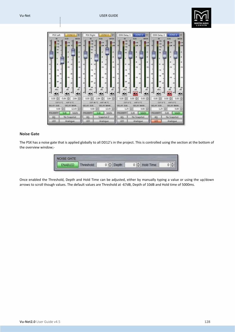
Vu‐Net USER GUIDE
Vu‐Net2.0 User Guide v4.5 128
…………
Noise Gate
The PSX has a noise gate that is applied globally to all DD12’s in the project. This is controlled using the section at the bottom of
the overview window;‐
Once enabled the Threshold, Depth and Hold Time can be adjusted, either by manually typing a value or using the up/down
arrows to scroll though values. The default values are Threshold at ‐67dB, Depth of 10dB and Hold time of 5000ms.
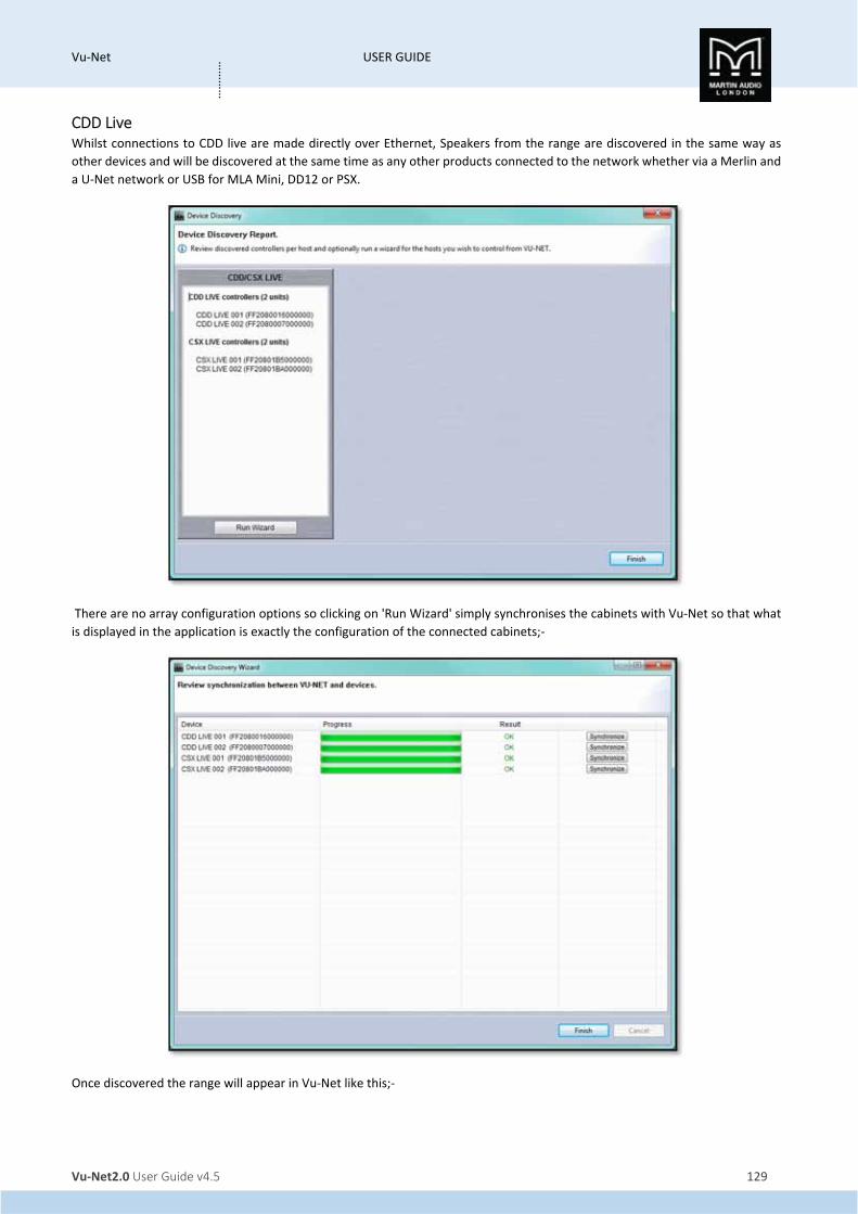
Vu‐Net USER GUIDE
Vu‐Net2.0 User Guide v4.5 129
…………
CDD Live Whilst connections to CDD live are made directly over Ethernet, Speakers from the range are discovered in the same way as
other devices and will be discovered at the same time as any other products connected to the network whether via a Merlin and
a U‐Net network or USB for MLA Mini, DD12 or PSX.
There are no array configuration options so clicking on 'Run Wizard' simply synchronises the cabinets with Vu‐Net so that what
is displayed in the application is exactly the configuration of the connected cabinets;‐
Once discovered the range will appear in Vu‐Net like this;‐

Vu‐Net USER GUIDE
Vu‐Net2.0 User Guide v4.5 130
…………
Each CDD Live device will be shown as an icon which includes the front grille LED. If you click on the cabinet to select it you can
then click on the LED which will illuminate on the icon and on the speaker to make it easy to identify which cabinets you re
controlling, useful particularly when you are arranging the overview screen in Vu‐Net to represent the physical positioning of the
system;‐
Right clicking on any of the speakers brings up a number of menu options;‐

Vu‐Net USER GUIDE
Vu‐Net2.0 User Guide v4.5 131
…………
'Open' has exactly the same function as double clicking on the speaker icon to open the full control window.
'Load Snapshot' opens the Snapshot window allowing you to recall any of the three Factory Snapshots or the fourth User
Snapshot;‐
'Save Snapshot' is the function used to store parameters that you have edited to the User Location "U". This location can be
recalled using the Load Snapshot command or by selecting Snapshot 4 using the button on the speaker connector panel. To store
a Snapshot once you have made all the parameter changes that you need, select 'Save Snapshot', you will see this window;‐
Click 'Save' and your setting are now stored and can be recalled when required.

Vu‐Net USER GUIDE
Vu‐Net2.0 User Guide v4.5 132
…………
'Import Snapshot' allows you to import a snapshot previously stored as a file on your PC. Selecting this option will open the
following Window;‐
Click on the 'Select' button to navigate to the location on your PC where your CDD‐Live files are located. If you would like to store
the imported snapshot directly to the User Snapshot location so it can be stored and selected in future without a PC connected
click on the 'Save to back‐panel user snapshot' box. If this is left un‐checked the snapshot settings will be imported but will be
lost when a new snapshot is selected from the rear panel switch.
Click 'Import' and the snapshot is downloaded from your PC to the CDD‐Live DSP.
'Export Snapshot' is used to store CDD‐Live settings as a file to your PC. This can be used to archive snapshots to build a library
of commonly used settings which can be quickly imported back into a system. This is the Export Snapshot Window;‐
You can choose to select the current active settings, a true snapshot of the system configuration, or to export one of the four
Snapshots stored in the cabinet DSP. If you choose to Export the current settings you should first give the Snapshot a name so it
is easy to identify when it is imported back into a cabinet "CDD‐Live8 Stereophonics" for example.

Vu‐Net USER GUIDE
Vu‐Net2.0 User Guide v4.5 133
…………
If you click on 'Export stored snapshot' you next need to select one of the four internal snapshots, either 1 to 3 which are the
factory snapshots or 4 which is the user snapshot location.
Next click 'Select' to navigate to an appropriate location on your PC to store the file and give it a suitable same.
Finally click 'Export' to upload the Snapshot to your PC.
'Synchronise' is a manual synchronise that duplicates the automatic synchronise that occurs when CDD Live is discovered to
ensure that what is displayed in Vu‐Net matches exactly the parameters stored within the cabinet DSP.
'Disconnect/Reconnect' allows you to disconnect and individual cabinet which will turn red once disconnected;‐
Selecting the same function will reconnect the cabinet and it will revert to the standard appearance.
'IP Settings' allows you to change from the default Dynamic IP to static. Clicking on the option brings up this window;‐

Vu‐Net USER GUIDE
Vu‐Net2.0 User Guide v4.5 134
…………
If you select Static IP you will need to enter a manual IP address and subnet mask in the same range as all other devices on the
network that you need to communicate with.
'Rename' allows you to give the cabinet a name of your choice up to 30 characters, this can also be accessed by selecting the
speaker and using the keyboard shortcut F2;‐
‘Select All’ selects all devices in the system Diagram, the keyboard shortcut for this is Ctrl + A.
‘Delete’ removes the selected CDD‐Live speaker. You will be prompted with the following Window to confirm the delete;‐
If you selected Delete accidentally or have changed your mind, click ‘Cancel’, otherwise click ‘OK' and the speaker will be removed
from the project.
Overview
Either double clicking or right clicking and selecting Open will bring up the overview option for the CDD Live which shows all CDD
Live speakers in the project, a separate overview shows all CSX Live subs;‐

Vu‐Net USER GUIDE
Vu‐Net2.0 User Guide v4.5 135
…………
This is the CSX Live Overview:‐
This gives an overview of the state of all CDD and CSX Live speakers allowing comprehensive monitoring of the system.
The box at the top will show any names that have been assigned to the cabinets by right clicking and selecting rename (or
selecting and pressing F2 in the System Diagram;‐

Vu‐Net USER GUIDE
Vu‐Net2.0 User Guide v4.5 136
…………
The gain fader allows gain adjustment from ‐40 to +15dB. Precise values can be entered by typing directly in the box below the
fader or values can be scrolled up or down using the up/down buttons. The increments that the up/down buttons will step is
determined in the Preferences section, by default it will be 0.25dB.
The mute button will mute the cabinet irrespective of the position of the gain fader and will turn red when active.
There is comprehensive metering available. The bargraph to the left of the fader shows input level up to the maximum before
input clip of +18dBu. The smaller meters to the right show the amplifier output levels for both the low frequency amplifier driving
the LF driver and the high frequency amplifier driving the compression driver and show level prior to limit. If the levels reach the
yellow segment you have reached the limiter threshold. A red segment indicated 3dB of gain reduction in the limiter.
There is also a temperature read out showing the temperature of the DSP and amplifier module;‐
There is delay available which is very useful for time aligning CDD Live when used as an extra fill with a larger mains system. The
maximum delay available is 1 second. Values can either be typed directly into the Delay field or scrolled up and down using the
arrow buttons. These increase or decrease the delay in increments of 10µs.
The Input allows the connection mode to be changed from the default which is Auto to Analogue or Dante. This can either be
done individually for each CDD or CSX Live or globally using the Input switch at the bottom of the overview Window. A global
change will bring up the flowing window;‐

Vu‐Net USER GUIDE
Vu‐Net2.0 User Guide v4.5 137
…………
Click ‘Cancel’ if you have changed your mind or ‘OK’ to accept the change of input mode. All CDD or CSX Live will display the new
input selection.
The Snapshot button acts in the same way as the Load and save Snapshot functions available from the right‐click menu in the
Project System Diagram. Clikcing on the Snapshot button brings up the option to Load or Save;‐
Selecting 'LOAD Snapshot' will bring up the Snapshot Menu with the currently active Snapshot shown highlighted in green;‐
Clicking on a new Snapshot number or letter will prompt you to confirm your selection;‐
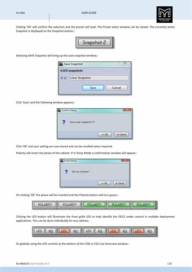
Vu‐Net USER GUIDE
Vu‐Net2.0 User Guide v4.5 138
…………
Clicking ‘OK’ will confirm the selection and the preset will load. The Preset select window can be closed. The currently active
Snapshot is displayed on the Snapshot button;‐
Selecting SAVE Snapshot will bring up the save snapshot window;‐
Click 'Save' and the following window appears;‐
Click 'OK' and your setting are now stored and can be recalled when required.
Polarity will invert the phase of the cabinet. If in Show Mode a confirmation window will appear;‐
On clicking ‘OK’ the phase will be inverted and the Polarity button will turn green;‐
Clicking the LED button will illuminate the front grille LED to help identify the DD12 under control in multiple deployment
applications. This can be done individually for any cabinet;‐
Or globally using the LED controls at the bottom of the CDD or CSX Live Overview window;‐

Vu‐Net USER GUIDE
Vu‐Net2.0 User Guide v4.5 139
…………
Pressing the “play" arrow will make the LEDs of all CDD Live illuminate in sequence, cycling round continually until you click
on the stop button Note that the global LED switches will overwrite any LEDs which have been activated on an individual
CDD or CSX Live. The back and forward buttons allow manual cycling of all cabinet LEDs, each click will extinguish the
currently illuminated LED and light the LED on the next or previous CDD or CSX Live.
EQ
The EQ button will open the EQ tab for that particular CDD or CSX Live speaker. The EQ window is virtually identical to all other
Vu‐Net controlled devices;‐
The window has three sections, the buttons along the top, the graphic display window and the controls on the right of the
window. First we will look at the buttons along the top.
First there are eight parametric EQ buttons plus the high pass filter;‐
As you can see there are a number of colour variations for these buttons. Unused bands are pale blue until they are selected for
editing by clicking on them in which case the colour goes to a brighter blue and the image shows the button depressed. Unused
is defined as the gain left at 0dB. Green buttons indicate a band that has either cut or boost applied, these will go a pale green
when selected. Note that the high pass filter is always active so will always appear green. The graphic view of the equalisation is
a relatively standard frequency response graph;‐
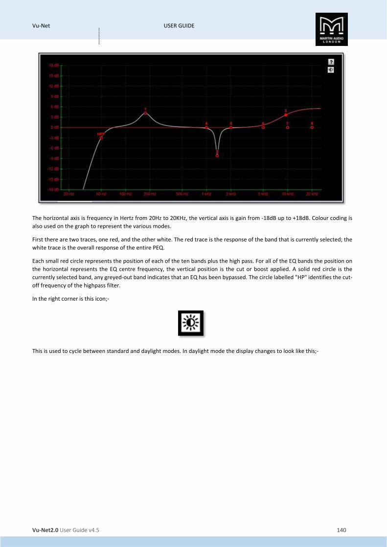
Vu‐Net USER GUIDE
Vu‐Net2.0 User Guide v4.5 140
…………
The horizontal axis is frequency in Hertz from 20Hz to 20KHz, the vertical axis is gain from ‐18dB up to +18dB. Colour coding is
also used on the graph to represent the various modes.
First there are two traces, one red, and the other white. The red trace is the response of the band that is currently selected; the
white trace is the overall response of the entire PEQ.
Each small red circle represents the position of each of the ten bands plus the high pass. For all of the EQ bands the position on
the horizontal represents the EQ centre frequency, the vertical position is the cut or boost applied. A solid red circle is the
currently selected band, any greyed‐out band indicates that an EQ has been bypassed. The circle labelled "HP" identifies the cut‐
off frequency of the highpass filter.
In the right corner is this icon;‐
This is used to cycle between standard and daylight modes. In daylight mode the display changes to look like this;‐
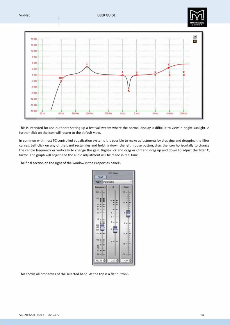
Vu‐Net USER GUIDE
Vu‐Net2.0 User Guide v4.5 141
…………
This is intended for use outdoors setting up a festival system where the normal display is difficult to view in bright sunlight. A
further click on the icon will return to the default view.
In common with most PC controlled equalisation systems it is possible to make adjustments by dragging and dropping the filter
curves. Left‐click on any of the band rectangles and holding down the left mouse button, drag the icon horizontally to change
the centre frequency or vertically to change the gain. Right‐click and drag or Ctrl and drag up and down to adjust the filter Q
factor. The graph will adjust and the audio adjustment will be made in real time.
The final section on the right of the window is the Properties panel;‐
This shows all properties of the selected band. At the top is a flat button;‐

Vu‐Net USER GUIDE
Vu‐Net2.0 User Guide v4.5 142
…………
This will zero the gain of the selected filter.
Next is a Filter type. Click on this and the drop down shows the options for each filter band;‐
The default is Parametric, the other otions are Low and High Shelf filters.
The High Pass Filter has the following options for filter type and slope;‐
Below are the three principal faders for adjusting the filter parameters;‐

Vu‐Net USER GUIDE
Vu‐Net2.0 User Guide v4.5 143
…………
Parameters can be changed on the properties panel in three ways. The faders can be drag and dropped to a new value, the value
can be scrolled up or down using the up/down buttons to the right of the value windows, and finally values can be directly typed
into the value windows. The response graph will adjust according to the new values and vice versa, adjustments in the graph
window will be reflected in the fader positions and values in the properties panel.
To summarise, there are four ways to adjust filter parameters;‐
1. Click and drag on the graph
2. Click and drag the properties faders
3. Use the up/down value buttons in the properties section
4. Directly type values into the value boxes.
Whilst this might seem over‐versatility, it is intended to offer several options to suit the way that the system is being operated.
If adjustments are being made with using a wireless tablet PC with a stylus whilst walking around a venue, certain options may
be easier to use than if you were sitting at a desk with a mouse plugged in to the PC.
Zones
Any cabinet can be a member of any (or none) of the twenty zones available which are labelled A to T which will gang together
all parameters for every cabinet in the zone. Note that all gain and delay parameters are offset ganged. If there is already a value
entered before adding a CDD Live cabinet to a zone this will be retained and subsequent changes to a value for any gain or delay
to any cabinet in the same zone will increase or decrease all values according to any edits you make but will retain the offset
between all values. To select a zone click on the Zone button at the top of the Overview page;‐

Vu‐Net USER GUIDE
Vu‐Net2.0 User Guide v4.5 144
…………
Click on the desired zone and it will be displayed on the zone button. The zones are colour coded to make it instantly obvious
which cabinets are on the same zones. Colours are as follows;‐
A is Blue K is Lavender B is Red L is Brown C is Green M is Turquoise D is Yellow N is Dark Brown E is Black O is Flesh F is Teal P is Light Green G is Deep Purple Q is Violet H is Moss Green R is Sand I is Pink S is Crimson J is Dull Green T is Azure
All functions on cabinets in the same zone will be duplicated regardless of which cabinet in the zone is used to make adjustments.
Note that all gain and delay parameters are offset ganged. If there is already a value entered before adding a CDD Live to a zone
this will be retained and subsequent changes to gain or delay to any cabinet in the same zone will increase or decrease all values
according to any edits you make but will retain the offset between all values;‐

Vu‐Net USER GUIDE
Vu‐Net2.0 User Guide v4.5 145
…………

Vu‐Net USER GUIDE
Vu‐Net2.0 User Guide v4.5 146
…………
Merlin The Merlin system controller is most often employed in MLA systems as a PC to U‐Net interface however the Merlin is a four
input, ten output audio processor with a host of extremely powerful functions available, all of which can be controlled via Vu‐
Net on exactly the same platform as MLA, MLA Compact, MLA Mini and other U‐Net compatible systems . As well as being used
as a simple matrix for controlling main arrays, side hangs and subs, it could easily be deployed to control conventional non‐
powered speaker products in use at events as stage front fills for example. The fact that everything can be controlled on the
same tablet PC running Vu‐Net makes system alignment and trim very straightforward indeed.
Gain, Mute & Limiters
Double clicking on the Merlin in the System overview page opens the Merlin System Control window which by default opens on
the first Gain/Mute/Limiter tab;‐
This has all input and output channel faders, meters and mute buttons available. As with the gain control on other Vu‐Net
controlled devices there is up to +15dB of gain or ‐40dB of cut available on all inputs and outputs. Metering is different for input
and output. Input shows absolute input level in dBu, the upper point is +22dBu which is the highest level signal which can be
applied to the input prior to clipping. The output meters display level before limit therefore their range will be determined by
the limiter threshold that has been set for that particular output. The metering shows green up until it reaches 3dB from the
limiter threshold whereupon it shows amber and finally red when the limiter threshold is reached. The upper most point of the
meter shows 3dB of gain reduction‐ essentially 3dB over the limit threshold.
Limiters are accessed by clicking on the ‘SHOW LIMITERS’ button;‐
This brings the output limiter controls up at the bottom of the window;‐

Vu‐Net USER GUIDE
Vu‐Net2.0 User Guide v4.5 147
…………
By default the time constants are set to Manual but they can be set to Automatic by clicking the Auto Time Constant button
which will then grey out the Attack and Release windows. Auto Time constants select the most appropriate time constants for
the frequency band that has been selected using the high and low pass filters in the PEQ window for each output. Parameters
are set by clicking on the drop‐down arrow and selecting the desired value from the list;‐
Clip level is a clip limiter designed to catch very fast peaks that might exceed the input headroom and can be set from +2dBu to
+34dBu in 1dB increments.
Peak Level is the principal limiter threshold with time constants determined by the Attack and Release controls. The threshold
range is from ‐10dBu to +22dBu also in 1dB increments.
Attack time is in milliseconds and can be the following values; 0.3, 0.4, 0.5, 0.7, 1.0, 1.4, 2.0, 2.8, 4.0, 5.7, 8.0, 11, 16, 23, 45 or
45ms
Release is specified as a multiple of the selected attack time and can be either 2x, 4x, 8x, 16x, 32x or 64x.
The limiter can be hidden again by clicking the ‘HIDE LIMITER’ button.
Routing
The Routing Tab brings up the routing matrix window which allows the input and output modes to be selected and the routing
freely configured;‐
The routing page is also used to label inputs and outputs, simply type the required name in the appropriate box. The name can
be up to 12 characters and will appear in all other Merlin tabs within Vu‐Net and on the unit itself but as there is limited space
on some windows, the Gain/Mute/Limiters page for example, we would recommend keeping name as short and succinct as
possible.
You may also select input or output routing to be AES3 or analogue by clicking on the boxes for all input and all outputs. Note
that it is possible to change inputs and outputs independently;‐

Vu‐Net USER GUIDE
Vu‐Net2.0 User Guide v4.5 148
…………
Note that selecting AES for either inputs or outputs changes how physical connections are made to the Merlin rear panel
connectors. This is duplicated on the routing page to help make it clear exactly how the Merlin needs to be patched, see the
chapter on the Merlin for more details. This for example is how the routing looks for a system with analogue inputs and AES3
outputs.
The routing matrix is shown with the inputs forming vertical columns and the outputs as horizontal lines. Each node can be
selected to route any input to any or all output. This is entirely freely configurable, there are no restrictions on where or how
many outputs and of the inputs are routed to. Note that any changes to the routing will remove any delay settings that have
been configured for any of the output channels. Here is a routed and labelled system;‐

Vu‐Net USER GUIDE
Vu‐Net2.0 User Guide v4.5 149
…………
Input Channels
The input and Output channel tabs are very similar to the PEQ window for MLA, MLD and MLA Compact with a few notable
differences;‐
As with other Vu‐Net EQ windows, the daylight icon is available;‐
This is used to cycle between standard and daylight modes. In daylight mode the display changes to look like this;‐
This is intended for use outdoors setting up a festival system where the normal display is difficult to view in bright sunlight. A
further click on the icon will return to the default view.

Vu‐Net USER GUIDE
Vu‐Net2.0 User Guide v4.5 150
…………
In common with most PC controlled equalisation systems it is possible to make adjustments by dragging and dropping the filter
curves. Left‐click on any of the band rectangles and holding down the left mouse button, drag the icon horizontally to change
the centre frequency or vertically to change the gain. Right‐click and drag or Ctrl and drag up and down to adjust the filter Q
factor. The graph will adjust and the audio adjustment will be made in real time.
The input that is being controlled is selected by clicking on one of the four buttons labelled A‐D;‐
Each input has eight filters which can be selected from the buttons along the top. Also available are a delay and gain button
which are “short cuts" to the delay and Gain/Mute/Limiter windows.
Filters may be manipulated in exactly the same way as the PEQ filters in the cabinets. The filter can be grabbed and drag and
dropped to select the desired frequency and gain, using right click to modify Q factor.
The parameter section allows precise values to be typed into the value windows, the faders drag and dropped or values cycled
up or down using the appropriate arrows. There are additional options for the filter type selected by the ‘Type’ drop down;‐
High Shelf 2nd order is a high shelf filter with gain available from ‐15dB to +15dB and Q from 0.25 up to 1.0;‐
Low Shelf 2nd Order is a low shelving filter also with +/‐15dB of gain and Q factor from 0.25 to 1.0;‐

Vu‐Net USER GUIDE
Vu‐Net2.0 User Guide v4.5 151
…………
There are no dedicated high and low pass filters on the inputs but High pass and lowpass with variable Q are options for filter
types;‐
You can also select ‘Show All’ to display all four input channels overlaid with different colours for each;‐

Vu‐Net USER GUIDE
Vu‐Net2.0 User Guide v4.5 152
…………
As well as eight bands of equalisation there are buttons for delay and gain;‐
These are a shortcut directly to the tabs for those functions.
The name allocated to each input is displayed above the EQ parameter controls on the top right of the window;‐
Output Channels
The output channel page is almost identical to the input pages;‐

Vu‐Net USER GUIDE
Vu‐Net2.0 User Guide v4.5 153
…………
There are naturally a few differences, the output channel being viewed is selected by the 10 buttons at the top of the window;‐
There are also eight filters available selected by the buttons top left but in addition there are also dedicated high and low pass
filters;‐
The last three buttons are short cuts to the delay, gain and limiter sections.
The parametric EQ have the same options as the input channels, parametric, high and low pass 2nd order shelving EQ and high
and low pass filters with variable Q;‐
The High and lowpass filters can be configured as either Bessel, Butterworth or Linkwitz Riley types with slopes of either 12, 18,
24 or 48dB per octave (48dB/oct is only available on Butterworth or Linkwitz Riley);‐

Vu‐Net USER GUIDE
Vu‐Net2.0 User Guide v4.5 154
…………
As with the input channels, the output channel name is shown above the EQ controls;‐
Delay
The delay window offers a sophisticated system for controlling time alignment if all systems routed via the Merlin. The maximum
through delay from input to output is 1 second so for example you can add 999.99ms to an output but then you will not be able
to add any delay to the input and vice versa, or you could have up to 500ms on the input and the same on the output.
It is important to note that if you make any changes to routing after you have set delays, all delays on a re‐routed channel will
be reset to zero.
This is how the routing window appears;‐
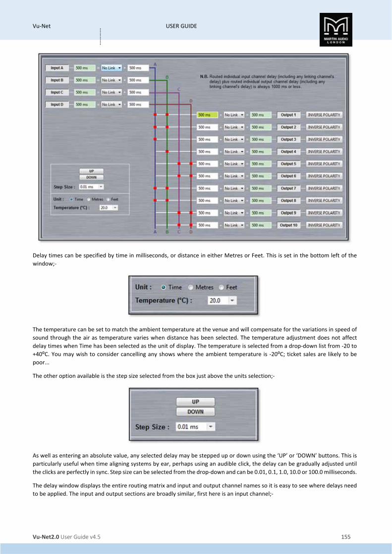
Vu‐Net USER GUIDE
Vu‐Net2.0 User Guide v4.5 155
…………
Delay times can be specified by time in milliseconds, or distance in either Metres or Feet. This is set in the bottom left of the
window;‐
The temperature can be set to match the ambient temperature at the venue and will compensate for the variations in speed of
sound through the air as temperature varies when distance has been selected. The temperature adjustment does not affect
delay times when Time has been selected as the unit of display. The temperature is selected from a drop‐down list from ‐20 to
+40⁰C. You may wish to consider cancelling any shows where the ambient temperature is ‐20⁰C; ticket sales are likely to be
poor...
The other option available is the step size selected from the box just above the units selection;‐
As well as entering an absolute value, any selected delay may be stepped up or down using the ‘UP’ or ‘DOWN’ buttons. This is
particularly useful when time aligning systems by ear, perhaps using an audible click, the delay can be gradually adjusted until
the clicks are perfectly in sync. Step size can be selected from the drop‐down and can be 0.01, 0.1, 1.0, 10.0 or 100.0 milliseconds.
The delay window displays the entire routing matrix and input and output channel names so it is easy to see where delays need
to be applied. The input and output sections are broadly similar, first here is an input channel;‐
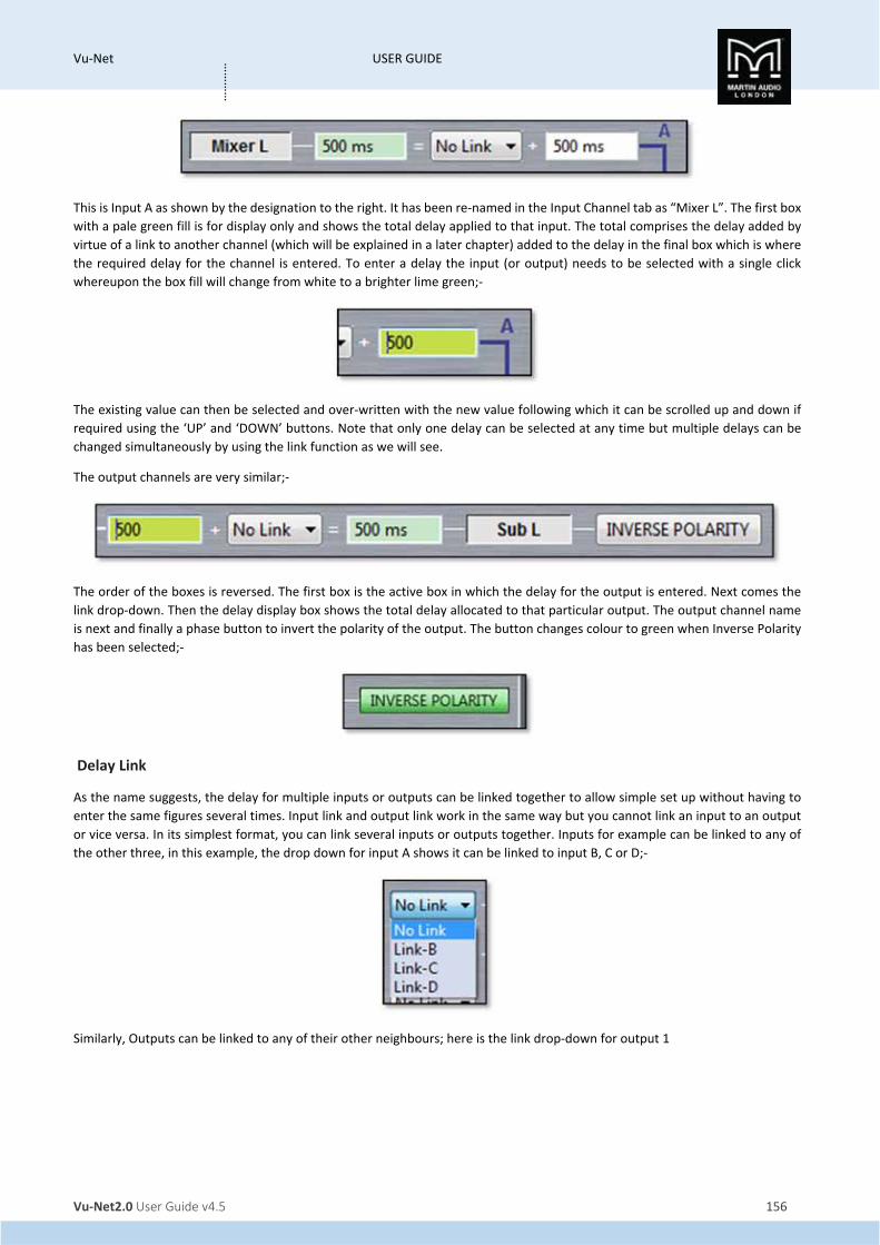
Vu‐Net USER GUIDE
Vu‐Net2.0 User Guide v4.5 156
…………
This is Input A as shown by the designation to the right. It has been re‐named in the Input Channel tab as “Mixer L”. The first box
with a pale green fill is for display only and shows the total delay applied to that input. The total comprises the delay added by
virtue of a link to another channel (which will be explained in a later chapter) added to the delay in the final box which is where
the required delay for the channel is entered. To enter a delay the input (or output) needs to be selected with a single click
whereupon the box fill will change from white to a brighter lime green;‐
The existing value can then be selected and over‐written with the new value following which it can be scrolled up and down if
required using the ‘UP’ and ‘DOWN’ buttons. Note that only one delay can be selected at any time but multiple delays can be
changed simultaneously by using the link function as we will see.
The output channels are very similar;‐
The order of the boxes is reversed. The first box is the active box in which the delay for the output is entered. Next comes the
link drop‐down. Then the delay display box shows the total delay allocated to that particular output. The output channel name
is next and finally a phase button to invert the polarity of the output. The button changes colour to green when Inverse Polarity
has been selected;‐
Delay Link
As the name suggests, the delay for multiple inputs or outputs can be linked together to allow simple set up without having to
enter the same figures several times. Input link and output link work in the same way but you cannot link an input to an output
or vice versa. In its simplest format, you can link several inputs or outputs together. Inputs for example can be linked to any of
the other three, in this example, the drop down for input A shows it can be linked to input B, C or D;‐
Similarly, Outputs can be linked to any of their other neighbours; here is the link drop‐down for output 1

Vu‐Net USER GUIDE
Vu‐Net2.0 User Guide v4.5 157
…………
Note that if you link a particular input to another, the “master" input cannot be linked to another channel. This also applies to
outputs.
In its simplest use, you can link one or more inputs or outputs to one other and use that to simultaneously change the delay of
all linked channels. Here inputs A, B & C have been linked to input D and a delay of 15ms has been applied to input D;‐
As you can see, although the individual channels A, B & C have nothing entered, the delay display shows 15ms for all inputs.
In addition to this simple matched delay, channels linked to others can also have a delay entered and the total delay will equal
the delay entered for the “master" channel plus whatever delay is entered for that channel. Any changes to the “master" delay
will be tracked by any channels linked to it. In this example, Output channels 2, 3 & 4 are linked to output 1. Output two has its
own delay of 10ms, output three 20ms and output four 30ms. We add 10ms to output 1 and see the following;‐
If we now increase the delay on Output one to 20ms we see this;‐

Vu‐Net USER GUIDE
Vu‐Net2.0 User Guide v4.5 158
…………
The delay on Output one will always match what is entered, the other three outputs will always match output one plus their
individual delay. Linking works in identical fashion to output channels.
Ganging
The Merlin has an extremely comprehensive ganging capability accessed from the Ganging tab. This operates in exactly the same
way as ganging between the same speaker model and allows ganging of an entire Merlin, individual inputs, individual outputs or
even individual parameters. The Ganging window appears like this;
All Merlins in the project will be available, our Master Merlin is shown at the top with our Slave Merlin below, the parameters
not visible can be accessed by scrolling down.
Note that all gain and delay parameters are offset ganged. If there is already a value entered before ganging is implemented this
will be retained and subsequent changes to a value to any ganged gain or delay will increase or decrease all values according to
any edits you make but will retain the offset between all values.
Ganging entire Merlins
By clicking on the Merlin name button we can gang any or all of the other Merlins by clicking again on the other Merlin name
buttons. Alternatively we can use the double arrow which appears when we hover over the button for a second. This gives us
the option of ganging all Merlins in the project selected with the window that appears;
Select as many Merlins as you need to gang and click again on the first Merlin name button. This shows all Merlins ganged;‐

Vu‐Net USER GUIDE
Vu‐Net2.0 User Guide v4.5 159
…………
Input and output Ganging
You can gang all input channel parameters on one or more Merlin by using the Input and Output buttons. Click on an unassigned
group and click on any input button you need to gang, either on one Merlin or several. Click on another unassigned group and
repeat for any outputs, choosing a new unassigned group for each new gang. This example shows all input parameters ganged
and outputs of each Merlin ganged in pairs as they are routing to stereo pairs;‐

Vu‐Net USER GUIDE
Vu‐Net2.0 User Guide v4.5 160
…………
Individual parameter ganging
You can use exactly the same process to gang individual parameters which could be in the same Merlin or across several. As with
output ganging, select unassigned Groups first then click on all parameters that you need to gang. The parameters are fairly
obvious by their icons, the input channels have mute, gain and eight bands of EQ, output channels have mute, gain, polarity, high
and low lass filter, eight bands of parametric EQ and limiters. If you are not sure what any icon is for just hover the cursor over
the button and its label appears;‐
Here we see a number of individual parameters ganged across a couple of Merlins;‐
Turning Ganging Off
To clear a gang just click again on the button you have just used, the gang controls toggle between ganged and un‐ganged with
each subsequent click. You can clear all ganging from a Merlin by clicking on its name button.
Un‐ganging with a single click makes it very easy to create practical ganged systems. For example, perhaps we want all Merlins
ganged with the exception of the mute controls so these can be changed independently to make set‐up easier. Simply gang all
Merlins by clicking on the name buttons, then click on all Mute icons to remove these from the ganging;‐

Vu‐Net USER GUIDE
Vu‐Net2.0 User Guide v4.5 161
…………
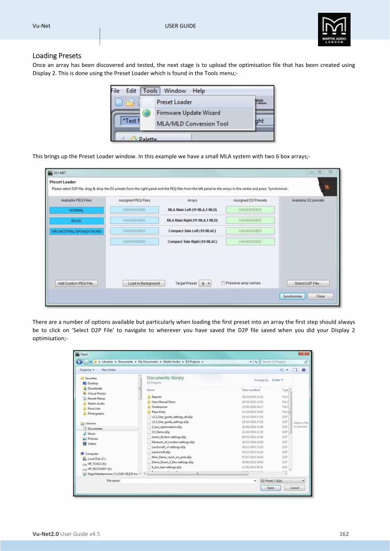
Vu‐Net USER GUIDE
Vu‐Net2.0 User Guide v4.5 162
…………
Loading Presets Once an array has been discovered and tested, the next stage is to upload the optimisation file that has been created using
Display 2. This is done using the Preset Loader which is found in the Tools menu;‐
This brings up the Preset Loader window. In this example we have a small MLA system with two 6 box arrays;‐
There are a number of options available but particularly when loading the first preset into an array the first step should always
be to click on ‘Select D2P File’ to navigate to wherever you have saved the D2P file saved when you did your Display 2
optimisation;‐
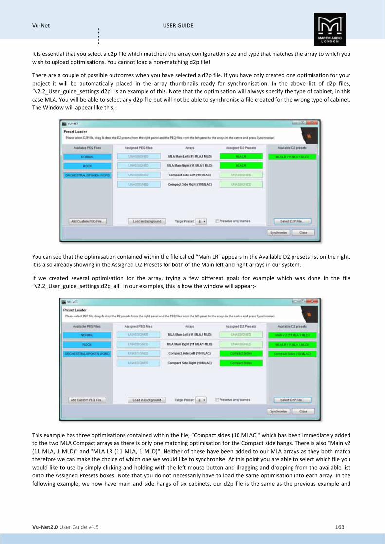
Vu‐Net USER GUIDE
Vu‐Net2.0 User Guide v4.5 163
…………
It is essential that you select a d2p file which matchers the array configuration size and type that matches the array to which you
wish to upload optimisations. You cannot load a non‐matching d2p file!
There are a couple of possible outcomes when you have selected a d2p file. If you have only created one optimisation for your
project it will be automatically placed in the array thumbnails ready for synchronisation. In the above list of d2p files,
“v2.2_User_guide_settings.d2p" is an example of this. Note that the optimisation will always specify the type of cabinet, in this
case MLA. You will be able to select any d2p file but will not be able to synchronise a file created for the wrong type of cabinet.
The Window will appear like this;‐
You can see that the optimisation contained within the file called “Main LR" appears in the Available D2 presets list on the right.
It is also already showing in the Assigned D2 Presets for both of the Main left and right arrays in our system.
If we created several optimisation for the array, trying a few different goals for example which was done in the file
“v2.2_User_guide_settings.d2p_all" in our examples, this is how the window will appear;‐
This example has three optimisations contained within the file, “Compact sides (10 MLAC)" which has been immediately added
to the two MLA Compact arrays as there is only one matching optimisation for the Compact side hangs. There is also "Main v2
(11 MLA, 1 MLD)" and "MLA LR (11 MLA, 1 MLD)". Neither of these have been added to our MLA arrays as they both match
therefore we can make the choice of which one we would like to synchronise. At this point you are able to select which file you
would like to use by simply clicking and holding with the left mouse button and dragging and dropping from the available list
onto the Assigned Presets boxes. Note that you do not necessarily have to load the same optimisation into each array. In the
following example, we now have main and side hangs of six cabinets, our d2p file is the same as the previous example and

Vu‐Net USER GUIDE
Vu‐Net2.0 User Guide v4.5 164
…………
contains two optimisations. We have dragged “User Manual 6 MLA" over to the Main left and right arrays, and “6 Box alt" over
to the side hangs;‐
Note that as well as uploading the optimisation file to each array, optimisation files created in Display version 2.2 onwards also
contain detail of the spl reference set during the design process, Vu‐Net uses this information to make changes to the gain of the
subs to maintain a good balance between the arrays and subs. These are the gain changes;‐
Optimisation reference of 110db or more: Sub Output Gain +10dB Optimisation reference 105dB: Sub Output Gain +5dB Optimisation reference 100dB or less: Sub Output Gain 0dB
PEQ files
On the left side of the Window you can see three available PEQ files, Normal, Rock, and Orchestra/Spoken Word. Note that the
available list of PEQ files may change depending on the product, MLA Mini for example only has a ‘Normal’ PEQ available. These
may also be dragged over to the Assigned PEQ file position;‐
It is important to do this not only to add some tonal EQ to the system but the PEQ synchronisation also performs a reset function
on certain parameters in the array. It matches the input setting for every cabinet in the array to the first enclosure and resets
the array delay to the default setting. Here we have applied the Rock PEQ to all arrays;‐

Vu‐Net USER GUIDE
Vu‐Net2.0 User Guide v4.5 165
…………
There is also the option to load a Custom PEQ file;‐
A PEQ file that has been created in an array can be saved as a file by right‐clicking on the array in the System Diagram window.
To up‐load the file at the same time as synchronising Optimisations, click on the ‘Add Custom PEQ File..."button and navigate to
the file location where the .mlap PEQ file is saved. Click on the file and it will appear in the list of available PEQ files and can be
dragged across in the same way as any other;
It is important to understand that a Custom PEQ will NOT perform the same system reset as one of the factory PEQ’s so we would
always recommend using a Factory PEQ for your first Sync and then add your own PEQ if you load any subsequent new
Optimisations or use the right‐click ‘PEQ‐ Load PEQ’ function in the array thumbnail on the System Diagram Window.
Note that you do not have to have the same PEQ applied to every array and if you wish to change the file prior to Synchronisation
just drag the new file over to the array and it will replace the existing file type;‐
Note that Optimisations created using Version 2.2 onwards contain version information that Vu‐net uses to make subtle changes
to the default EQ curves loaded.
Other options
There are some other options available in the Preset Loader. From right to left you will find ‘Preserve array names’;‐
If you have already named your arrays check with box prior to synchronisation. Without it the arrays will be renamed with the
same name as the D2 optimisation.
Target snapshot allows you to select the cabinet snapshot into which an optimisation will be loaded;‐

Vu‐Net USER GUIDE
Vu‐Net2.0 User Guide v4.5 166
…………
There are ten available labelled from B to K. A is the default factory preset with basic box EQ which may be used whilst checking
a system or in an emergency, all other are available for your optimisations and once uploaded can be selected in a few seconds.
Select the desired location using the drop down button.
Load in Background is very useful for uploading new optimisations after your first files have been synchronised. Clicking on the
Load in Background button removes the PEQ options and the window appears as follows;‐
The PEQ already uploaded will be preserved and if you select an alternative snapshot to the one currently being used you can
even synchronise while the system is in use. It will synchronise in the background as the name suggests without disturbing system
performance and you can then wait for an appropriate break in a show or rehearsal to select the new snapshot.
Synchronise
Once you have completed your selection of the available options, the final step is to click on the Synchronise button to start the
Preset upload. You will see a series of Windows that show the process of the upload including the following;‐
The presets are loaded to each array in turn, in our example first the left array. The optimisation is then stored in a snapshot;‐

Vu‐Net USER GUIDE
Vu‐Net2.0 User Guide v4.5 167
…………
The snapshot will be recalled;‐
The PEQ’s will be loaded. This step will not take place if you selected ‘Load in Background’;‐
It will repeat these steps for all arrays on the network. Once finished you will see this window;‐
You can then close the Preset Loader. It can be re‐used whenever you wish to upload new optimisations. In particular if you have
created several optimisations for an array in the same D2P file or independently, just repeat the Preset Loading process selecting
the same D2p file but dragging the alternative optimisations into the array. Select the load in Background option as there is no
need to keep uploading PEQ files, and select a different target preset. Once uploaded you can compare your optimisations by
selecting the different presets by right‐clicking on the array thumbnail and choosing the 'Load Preset' option.

Vu‐Net USER GUIDE
Vu‐Net2.0 User Guide v4.5 168
…………
Master Overview Vu‐Net features a Master Overview window intended for use following set‐up when it is useful to view the entire system on a
single page with the ability to monitor all levels and make changes to essential functions.
Here we see a project with a variety of U‐Net enabled devices connected including an array of one MLA and an MLD, a flown
MLA Mini system, a PSX, DDD12 and a Merlin;‐
If we click on the Master Overview button;‐
A new tab is opened with a window showing all devices in operation;‐

Vu‐Net USER GUIDE
Vu‐Net2.0 User Guide v4.5 169
…………
The MLA array shows the input bargraph plus all Cell output bargraphs for all cabinets in the array, all other arrays and speakers
show input and output levels and all Merlins display input and output meters. All bargraphs are updated in real time which makes
monitoring an entire system very easy from a single page.
In addition to monitoring the meter response, essential features are accessible. The function control is the same for all Array and
speaker types;‐
The top line shows the input configuration for the array, if this needs to be changed clicking on the top line takes you to the array
input overview screen where you can change the input configuration. If the array isn't already open it will be opened by clicking
on this button.
On the second row is GAIN. Gain adjustments can be made by clicking on this button. A pop out fader appears which can be
adjusted in real time, either by dragging and dropping the fader knob until the desired gain value is displayed,
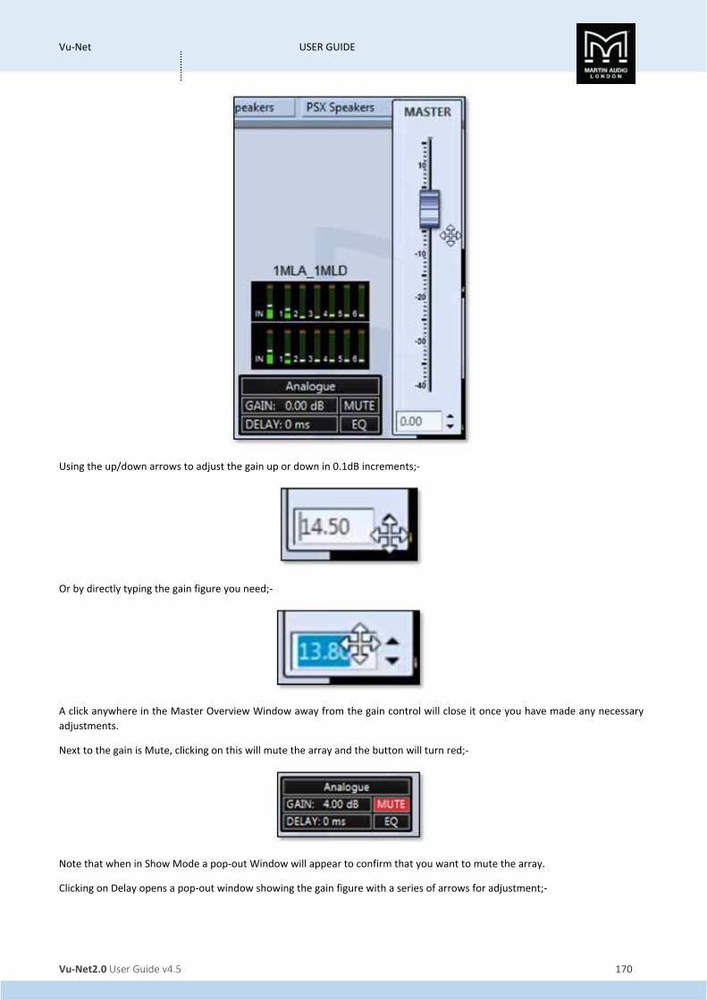
Vu‐Net USER GUIDE
Vu‐Net2.0 User Guide v4.5 170
…………
Using the up/down arrows to adjust the gain up or down in 0.1dB increments;‐
Or by directly typing the gain figure you need;‐
A click anywhere in the Master Overview Window away from the gain control will close it once you have made any necessary
adjustments.
Next to the gain is Mute, clicking on this will mute the array and the button will turn red;‐
Note that when in Show Mode a pop‐out Window will appear to confirm that you want to mute the array.
Clicking on Delay opens a pop‐out window showing the gain figure with a series of arrows for adjustment;‐

Vu‐Net USER GUIDE
Vu‐Net2.0 User Guide v4.5 171
…………
Clicking on the arrows will adjust the delay up or down by either 100's, 10s, individual or tenths of a millisecond making it very
quick and easy to enter a precise figure. As with gain, clicking anywhere else once you have completed adjustments will close
the window.
The Window for PSX is slightly different in that it has individual delay adjustment for both the sub and main outputs;‐
The EQ button will take you directly to the EQ Window for the array, opening it in a new tab if it is not already present.
Double clicking on Merlin will also open it in a new tab, the tab on view will be the last tab that was in use if the Merlin has
already been opened, or the Gain/Mute/Limiters tab if it is not already open.
The layout of the Master Overview screen will by default show the arrays in size order. This will automatically re‐size to ensure
that all elements fit in the window. Elements can be dragged and dropped to arrange the system to your requirements. A series
of buttons and a display on the right hand size of the window allow adjustment of the view and shows the current zoom;‐
'Fit to screen' offers a quick method of re‐sizing the window to ensure that all elements are visible.
System Layout' will move all elements to match the layout in the system diagram, If you moved all devices during set‐up in the
system diagram to represent their actual physical positions around the venue default, clicking on this button will duplicate your
layout in the Master Overview.
You can choose to return to the default Auto layout by clicking the Auto Layout button, this will bring up a confirmation window

Vu‐Net USER GUIDE
Vu‐Net2.0 User Guide v4.5 172
…………
Clicking 'Yes' or pressing Return will reset the layout to the default and the display will confirm the new zoom and that Automatic
layout has been activated;‐
As soon as you move any elements or zoom in or out the Auto Layout will disappear.
The Zoom in and out buttons will change the zoom in steps of 10% up or down. This can also be achieved if you have a mouse
connected with a scroll wheel. Zoom 1:1 restores the window to 100% regardless of whether any elements will be outside of the
view.

Vu‐Net USER GUIDE
Vu‐Net2.0 User Guide v4.5 173
…………
Show Mode Show mode is designed to offer a degree of protection once set‐up is complete and a show has started to prevent the user from
muting part of the system accidentally. With Show Mode inactive during set‐up, all mutes can be used as and when required
with a simple mouse click; the array will mute and unmute instantly under command of the button. When Show Mode is
activated, clicking a Mute button anywhere in the system will bring up a confirmation window;‐
The window is slightly different for a zone mute;‐
For a DD12 or CDD Live speaker;‐
The Sub and main Mutes for the PSX have different mute messages;‐

Vu‐Net USER GUIDE
Vu‐Net2.0 User Guide v4.5 174
…………
And finally the input and output channels on a Merlin;‐
If you definitely want to mute the array, zone or speaker, click 'Yes' or press Return. If you accidentally clicked on a Mute, click
'No' and the window will disappear with no change to the mute state.
Un‐muting part of the system could also potentially be destructive so a similar message will prompt you to confirm the action;‐
Note that the Master system Mute on the toolbar is not affected by Show Mode, as it is so destructive it always produces a
prompt to verify that you wish to proceed.
The Output diagnostics for MLAS, MLA Compact or MLA Mini is also unavailable in Show Mode. Double clicking on the array
thumbnail will bring up the following window;‐
If an array has the diagnostics window already open before activating Show Mode, the Mute Array button and individual cell
mutes for each cabinet will be unavailable, you will see the following window if you click on any of these;‐

Vu‐Net USER GUIDE
Vu‐Net2.0 User Guide v4.5 175
…………
You will however be able to click on the 'Hide' button to close the diagnostics screen and any muted cells will be un‐muted. You
will not be able to go back to the diagnostics page until Show mode is switched off.

Vu‐Net USER GUIDE
Vu‐Net2.0 User Guide v4.5 176
…………
Firmware Updates Martin Audio is constantly striving to make improvements to the MLA family of products. The phenomenal processing power
available makes them extremely future proof so as Martin Audio improve the optimisation capabilities of Display2 or add
additional functions to Vu‐Net. The MLA Series will seamless run the improvements. Occasionally an update to the cabinet
Firmware is needed which is catered for in Vu‐Net using the Firmware update Wizard.
If you have sub‐rented additional cabinets you may find that your rental partner has not been quite so diligent in keeping their
system firmware up to date and device discovery will show some cabinets with a differing firmware versions. In this instance it
is essential to update firmware on the miss‐matched cabinets, do not try to run a system with a mixture of firmware, it could
cause compatibility
In common with many digital systems, a firmware update puts the product in a venerable state known as “boot mode”. It is vital
that the firmware update is not interrupted by either a mains outage, cable disconnect or closing Vu‐Net. Any of these could
render the product unusable which may mean a return to Martin Audio for repair therefore you should take every possible
precaution before commencing a firmware update. ALWAYS use a hard wired connection from your PC to the system, do not
rely on Wi‐Fi. Always use your PC with its mains PSU, do not rely on battery power. Try and ensure that your mains supply is
reliable and is not likely to fail mid‐update. Finally, the update process takes around 13 minutes per enclosure so on a large
system is very time consuming. It is strongly recommended that firmware is checked when a system is prepped prior to a show
back at your warehouse, it is not a task for set‐up on a show day.
Get Firmware Updates
To make sure that you are loading the latest updates Vu‐Net includes a system for checking that you have the latest firmware
files installed so they are available to upgrade your system. The files are held in a server at Martin Audio and are accessed over
the internet so to get the latest files you will need internet connectivity to your PC. Note that you can get Firmware update files
completely independently, you do not need to be connected to an MLA system, the simple method is to take the tablet PC
supplied with your system to your office, connect to the web and check for updates. Note also that whenever new firmware is
released you will be notified by e‐mail.
The Get Firmware Updates button is in the bottom right corner of the Vu‐Net window;‐
Click on the button and the following Window gives you three options;‐

Vu‐Net USER GUIDE
Vu‐Net2.0 User Guide v4.5 177
…………
The first option as described accesses the firmware server via the internet. The URL for the Update file location is retained in the
Vu‐Net Preferences;‐
Do not change this unless told to do so by Martin Audio!
Click on the ‘DOWNLOAD THE LATEST FIRMWARE FILES’ option and you will see the flowing window;‐
This is usually very rapid but depends on the speed of your internet connection. The latest files are now saved within Vu‐Net
ready for an upgrade. At the top of the Firmware Update window you will see;‐

Vu‐Net USER GUIDE
Vu‐Net2.0 User Guide v4.5 178
…………
The Second option is to proceed with the update using the already installed firmware files. This is perfectly acceptable if you
have already uploaded the latest files following a message from Martin Audio that there is a new release, or if you have
periodically gone on line to load the latest files routinely. Clicking the ‘PROCEED WITH FIRMWARE UPGRADE USING VUNET
FIRMWARE DATABASE’ button and the window closes and the Firmware Update process starts.
The final option is to update the Firmware using an external VUA file. If for any reason you are unable to update the Firmware
database via the internet if it is impractical to connect the Tablet PC for example, but have access to the web on another
computer, it is possible to download the firmware file and transfer it to the system Tablet via a USB drive or similar.
Clicking on the ‘PROCEED WITH FIRMWARE UPGRADE USING EXTERNAL VUA FILE’ button will bring up a file browser. Navigate
to the drive where the VUA file is located, in this case on a Martin Audio USB Key;‐
Select the VUA file, it will be saved and the update wizard will commence.
Starting a Firmware Update.
Selecting the Firmware Update Wizard in the Vu‐Net Tools menu opens the same window as the Get Firmware updates to double‐
check that you have the latest versions. Assuming that you have definitely installed the very latest versions you can click on
‘PROCEED WITH FIRMWARE UPGRADE USING VUNET FIRMWARE DATABASE’. Vu‐Net will scan the U‐Net network for connected
devices in the same way as a Device Discovery;‐
When the scan is complete, a window will appear with a list of all devices found together with their type, Serial number and the
installed firmware;‐

Vu‐Net USER GUIDE
Vu‐Net2.0 User Guide v4.5 179
…………
Vu‐Net compares the discovered Firmware version with the latest version stored in its database and will indicate in the final
column whether an upgrade is available. In this instance a single Merlin and twelve MLA have been found and all have up to date
firmware however we can still proceed with an update to show how the process works.
In the left hand column there is a check box to select any device which you would like to update. The button at the bottom gives
you the option to select all cabinets if required with a single click. If you have made an error in selecting devices you can use the
'Deselect' all switch to start again. We will do an update on the final two MLA;‐
Click next and you see the following window;‐

Vu‐Net USER GUIDE
Vu‐Net2.0 User Guide v4.5 180
…………
The current firmware is shown and the final column has an option to select the required firmware which in most cases would
be a new version but could be an old firmware if say a bug has been found in a current version and it is necessary to downgrade
to an earlier version. If there are several versions available, clicking on the Upgrade/Downgrade cell will bring up a drop‐down
showing the version numbers. Select the version you wish to use and it will appear in the final column;‐
Click on ‘Next’ to start the update. You will first see the following warning to ensure that every measure has been taken to
ensure that the update will complete successfully;‐
Click 'Next' and the upgrade will start. A progress window will appear showing the processes in the upgrade taking place. The
system tackles one device at a time, placing it into Boot Mode, uploading the firmware and rebooting the device back into an
operating mode;‐

Vu‐Net USER GUIDE
Vu‐Net2.0 User Guide v4.5 181
…………
Once completed you will see the following;‐
Click ‘OK’ and then click on ‘Finish’ on the Update Progress Window. The update is complete.
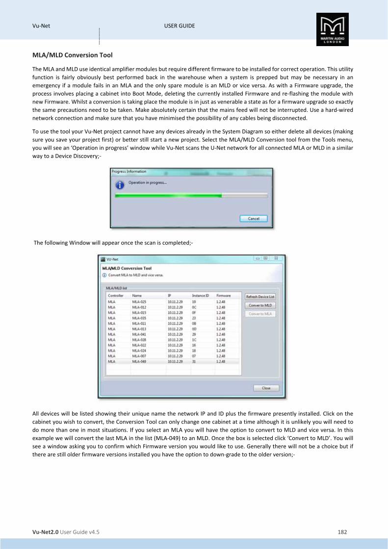
Vu‐Net USER GUIDE
Vu‐Net2.0 User Guide v4.5 182
…………
MLA/MLD Conversion Tool
The MLA and MLD use identical amplifier modules but require different firmware to be installed for correct operation. This utility
function is fairly obviously best performed back in the warehouse when a system is prepped but may be necessary in an
emergency if a module fails in an MLA and the only spare module is an MLD or vice versa. As with a Firmware upgrade, the
process involves placing a cabinet into Boot Mode, deleting the currently installed Firmware and re‐flashing the module with
new Firmware. Whilst a conversion is taking place the module is in just as venerable a state as for a firmware upgrade so exactly
the same precautions need to be taken. Make absolutely certain that the mains feed will not be interrupted. Use a hard‐wired
network connection and make sure that you have minimised the possibility of any cables being disconnected.
To use the tool your Vu‐Net project cannot have any devices already in the System Diagram so either delete all devices (making
sure you save your project first) or better still start a new project. Select the MLA/MLD Conversion tool from the Tools menu,
you will see an ‘Operation in progress’ window while Vu‐Net scans the U‐Net network for all connected MLA or MLD in a similar
way to a Device Discovery;‐
The following Window will appear once the scan is completed;‐
All devices will be listed showing their unique name the network IP and ID plus the firmware presently installed. Click on the
cabinet you wish to convert, the Conversion Tool can only change one cabinet at a time although it is unlikely you will need to
do more than one in most situations. If you select an MLA you will have the option to convert to MLD and vice versa. In this
example we will convert the last MLA in the list (MLA‐049) to an MLD. Once the box is selected click ‘Convert to MLD’. You will
see a window asking you to confirm which Firmware version you would like to use. Generally there will not be a choice but if
there are still older firmware versions installed you have the option to down‐grade to the older version;‐

Vu‐Net USER GUIDE
Vu‐Net2.0 User Guide v4.5 183
…………
One you have selected the firmware click on ‘Upgrade’, you will see a window which shows the progress of the firmware
conversion;‐
When the conversion is finished you will see a confirmation window;‐
Click ‘OK’ and close the update progress monitor. Vu‐Net will then re‐scan U‐Net to check all connected devices;‐

Vu‐Net USER GUIDE
Vu‐Net2.0 User Guide v4.5 184
…………
You will then see the same Window as previously showing all connected devices, note how the last enclosure in the list is now
an MLD;‐
The window can be closed and a system discovered and used in the normal way.


![Amplifiers • BT - RE Audioreaudio.com/catalog[2015].pdfAmplifiers • BT Product images may differ from actual product appearances ... The RE Audio’s XXX6.5C/XXX6.9C components](https://img.pdfslide.us/doc/110x75/5aa5f1bd7f8b9ab4788dda05/amplifiers-bt-re-2015pdfamplifiers-bt-product-images-may-differ-from.jpg)