Embed Size (px)
Citation preview
Bare Metal Server
User Guide
Issue 22
Date 2020-01-20
HUAWEI TECHNOLOGIES CO., LTD.
Copyright © Huawei Technologies Co., Ltd. 2020. All rights reserved.
No part of this document may be reproduced or transmitted in any form or by any means without priorwritten consent of Huawei Technologies Co., Ltd. Trademarks and Permissions
and other Huawei trademarks are trademarks of Huawei Technologies Co., Ltd.All other trademarks and trade names mentioned in this document are the property of their respectiveholders. NoticeThe purchased products, services and features are stipulated by the contract made between Huawei andthe customer. All or part of the products, services and features described in this document may not bewithin the purchase scope or the usage scope. Unless otherwise specified in the contract, all statements,information, and recommendations in this document are provided "AS IS" without warranties, guaranteesor representations of any kind, either express or implied.
The information in this document is subject to change without notice. Every effort has been made in thepreparation of this document to ensure accuracy of the contents, but all statements, information, andrecommendations in this document do not constitute a warranty of any kind, express or implied.
Issue 22 (2020-01-20) Copyright © Huawei Technologies Co., Ltd. i
Contents
1 Common Operations...............................................................................................................1
2 Instance......................................................................................................................................62.1 Creating a BMS........................................................................................................................................................................ 62.1.1 Creating a BMS..................................................................................................................................................................... 62.1.2 Creating a BMS Supporting Quick Provisioning..................................................................................................... 162.1.3 Creating a Dedicated BMS............................................................................................................................................. 172.1.4 Creating a BMS Using a Private Image......................................................................................................................192.2 Viewing BMS Information.................................................................................................................................................. 192.2.1 Viewing BMS Creation Statuses................................................................................................................................... 202.2.2 Viewing BMS Details........................................................................................................................................................ 202.2.3 Exporting the BMS list..................................................................................................................................................... 212.3 Logging In to a Linux BMS................................................................................................................................................ 222.3.1 Linux BMS Login Methods............................................................................................................................................. 222.3.2 Remotely Logging In to a BMS..................................................................................................................................... 222.3.3 Logging In to a BMS Using an SSH Key Pair........................................................................................................... 242.3.4 Logging In to a BMS Using a Password.....................................................................................................................262.4 Logging In to a Windows BMS.........................................................................................................................................272.4.1 Windows BMS Login Methods...................................................................................................................................... 272.4.2 Logging In to a BMS Remotely Using MSTSC......................................................................................................... 272.5 Managing BMSs.................................................................................................................................................................... 282.5.1 Changing the Name of a BMS...................................................................................................................................... 282.5.2 Resetting the BMS Password......................................................................................................................................... 292.5.3 Stopping BMSs................................................................................................................................................................... 312.5.4 Restarting BMSs................................................................................................................................................................. 312.5.5 Reinstalling the OS........................................................................................................................................................... 322.5.6 Rebuilding a BMS.............................................................................................................................................................. 342.5.7 Backing Up a BMS.............................................................................................................................................................362.5.8 Releasing a BMS................................................................................................................................................................ 362.6 Using User Data and Metadata....................................................................................................................................... 372.6.1 Injecting User Data into BMSs...................................................................................................................................... 372.6.2 Metadata.............................................................................................................................................................................. 452.7 Installing Drivers and Toolkits.......................................................................................................................................... 522.7.1 Installing the NVIDIA GPU Driver and CUDA Toolkit on a P1 BMS.................................................................52
Bare Metal ServerUser Guide Contents
Issue 22 (2020-01-20) Copyright © Huawei Technologies Co., Ltd. ii
2.7.2 Installing the NVIDIA GPU Driver and CUDA Toolkit on a P2 BMS.................................................................55
3 Image....................................................................................................................................... 603.1 Private Image Overview..................................................................................................................................................... 603.2 Creating a Private Image from a BMS...........................................................................................................................613.3 Creating a Private Image from an External Image File........................................................................................... 633.4 Convert Image File Formats.............................................................................................................................................. 64
4 Disk........................................................................................................................................... 704.1 Disk Types................................................................................................................................................................................ 704.2 Attaching Data Disks........................................................................................................................................................... 724.3 Initializing Data Disks..........................................................................................................................................................744.3.1 Introduction to Data Disk Initialization Scenarios and Partition Styles......................................................... 744.3.2 Initializing a Windows Data Disk (Windows Server 2016)................................................................................. 764.3.3 Initializing a Linux Data Disk (fdisk).......................................................................................................................... 874.3.4 Initializing a Linux Data Disk (parted).......................................................................................................................924.3.5 Initializing a Windows Data Disk Greater Than 2 TB (Windows Server 2012)........................................... 974.3.6 Initializing a Linux Data Disk Greater Than 2 TB (parted)...............................................................................1064.4 Detaching a Disk................................................................................................................................................................ 1104.5 Expanding Disk Capacity..................................................................................................................................................111
5 Key Pair and Password.......................................................................................................1125.1 Using an SSH Key Pair...................................................................................................................................................... 1125.2 (Optional) Installing the One-Click Password Reset Plug-in.............................................................................. 1175.3 Obtaining the Password of a Windows BMS............................................................................................................ 1225.4 Deleting the Password of a Windows BMS............................................................................................................... 123
6 Network.................................................................................................................................1256.1 EIP............................................................................................................................................................................................ 1256.1.1 Overview............................................................................................................................................................................ 1256.1.2 Binding an EIP to a BMS...............................................................................................................................................1266.1.3 Unbinding an EIP from a BMS....................................................................................................................................1276.1.4 Changing an EIP Bandwidth........................................................................................................................................1276.2 VPC.......................................................................................................................................................................................... 1286.2.1 Overview............................................................................................................................................................................ 1286.2.2 Changing the Private IP Address................................................................................................................................1306.2.3 Managing Virtual IP Addresses.................................................................................................................................. 1316.2.4 Setting the Source/Destination Check for a NIC.................................................................................................. 1336.2.5 Enabling IPv4/IPv6 Dual Stack................................................................................................................................... 1336.3 High-Speed Network.........................................................................................................................................................1356.3.1 Overview............................................................................................................................................................................ 1356.3.2 Managing High-Speed Networks.............................................................................................................................. 1386.4 Enhanced High-Speed Network.................................................................................................................................... 1396.4.1 Overview............................................................................................................................................................................ 1396.4.2 Adding an Enhanced High-Speed NIC..................................................................................................................... 142
Bare Metal ServerUser Guide Contents
Issue 22 (2020-01-20) Copyright © Huawei Technologies Co., Ltd. iii
6.4.3 Deleting an Enhanced High-Speed NIC.................................................................................................................. 1436.4.4 Configuring an Enhanced High-Speed NIC (SUSE Linux Enterprise Server 12)........................................ 1446.4.5 Configuring an Enhanced High-Speed NIC (SUSE Linux Enterprise Server 11)........................................ 1476.4.6 Configuring an Enhanced High-Speed NIC (Red Hat, CentOS, Oracle Linux, and EulerOS)................1506.4.7 Configuring an Enhanced High-Speed NIC (Ubuntu)........................................................................................ 1576.4.8 Configuring an Enhanced High-Speed NIC (Windows Server)....................................................................... 1636.5 User-defined VLAN............................................................................................................................................................ 1686.5.1 Overview............................................................................................................................................................................ 1686.5.2 Configuring a User-defined VLAN (SUSE Linux Enterprise Server 12).........................................................1706.5.3 Configuring a User-defined VLAN (SUSE Linux Enterprise Server 11).........................................................1756.5.4 Configuring a User-defined VLAN (Red Hat, CentOS, Oracle Linux, and EulerOS)................................ 1806.5.5 Configuring a User-defined VLAN (Ubuntu)......................................................................................................... 1836.5.6 Configuring a User-defined VLAN (Windows Server)........................................................................................ 1876.6 IB Network............................................................................................................................................................................ 1926.6.1 Overview............................................................................................................................................................................ 1926.7 User-defined Network...................................................................................................................................................... 1936.7.1 Overview............................................................................................................................................................................ 1936.7.2 Creating and Managing a User-defined Network............................................................................................... 1946.8 User-defined Network ACL............................................................................................................................................. 1976.8.1 Overview............................................................................................................................................................................ 1976.8.2 Configuration Examples................................................................................................................................................1986.8.3 Creating and Managing a User-defined Network ACL...................................................................................... 200
7 Security.................................................................................................................................. 2047.1 Security Group..................................................................................................................................................................... 2047.1.1 Adding Security Group Rules...................................................................................................................................... 2047.1.2 Security Group Configuration Examples................................................................................................................. 2067.1.3 Changing a Security Group..........................................................................................................................................2087.2 Project and Enterprise Project........................................................................................................................................ 209
8 Permissions Management................................................................................................. 2118.1 Creating a User and Granting Permissions................................................................................................................2118.2 Creating a Custom Policy.................................................................................................................................................2128.3 Examples of Custom Policies for Networks and ACLs........................................................................................... 214
9 Resources and Tags.............................................................................................................2209.1 Tag........................................................................................................................................................................................... 2209.1.1 Overview............................................................................................................................................................................ 2209.1.2 Adding Tags...................................................................................................................................................................... 2219.1.3 Searching for Resources by Tag................................................................................................................................. 2229.1.4 Deleting Tags.................................................................................................................................................................... 2239.2 Resource Location.............................................................................................................................................................. 2239.3 Adjusting Resource Quotas............................................................................................................................................. 225
10 Server Monitoring.............................................................................................................227
Bare Metal ServerUser Guide Contents
Issue 22 (2020-01-20) Copyright © Huawei Technologies Co., Ltd. iv
10.1 Overview............................................................................................................................................................................. 22710.2 Supported Monitoring Metrics (with Agent Installed)....................................................................................... 22810.3 Supported Monitoring Metrics (with Agent Installed, CN East-Shanghai1)............................................... 249
11 Auditing of Key Operations............................................................................................25311.1 Viewing Traces...................................................................................................................................................................25311.2 BMS Operations Recorded by CTS............................................................................................................................. 254
12 Troubleshooting................................................................................................................ 25612.1 What Can I Do If I Cannot Log In to My BMS or the BMS EVS Disk Is Lost After the BMS Is Started orRestarted?.....................................................................................................................................................................................25612.2 What Should I Do If a Key Pair Created Using PuTTYgen Cannot Be Imported to the ManagementConsole?........................................................................................................................................................................................ 25612.3 What Can I Do If Disks Cannot Be Attached to a BMS That Restarts Abnormally?.................................25812.4 What Can I Do If an EVS Disk Attached to a Windows BMS Is in Offline State?......................................259
A Change History....................................................................................................................260
Bare Metal ServerUser Guide Contents
Issue 22 (2020-01-20) Copyright © Huawei Technologies Co., Ltd. v
1 Common Operations
When using BMSs, you may encounter various problems, such as remotely loggingin to a BMS, expanding disk capacity, backing up a BMS, and reinstalling the OS.This section provides navigation to common operations to help you with theseproblems.
Configure Permissions
Before creating BMSs, you may need to create IAM users for employees based onthe organizational structure of your enterprise. Each IAM user has their ownsecurity credentials, providing access to BMS resources.
To configure permissions, perform the following operations:
● Creating a User and Granting Permissions● Creating a Custom Policy
Create and Manage a BMS
General Operations
Perform the following steps to use a BMS:
1. Create a BMS by following the instructions in Creating a BMS.If the BMS quota is insufficient, you can apply to increase the quota byfollowing the instructions in Adjusting Resource Quotas.
2. Log in to the BMS. The login mode varies depending on the BMS OS.– Linux BMS: Remotely Logging In to a BMS, Logging In to a BMS Using
an SSH Key Pair, or Logging In to a BMS Using a Password– Windows BMS: Logging In to a BMS Remotely Using MSTSC
3. Stop the BMS by following the instructions in Stopping BMSs.4. Delete the BMS by following the instructions in Releasing a BMS.
Billing Management
You can renew your yearly/monthly BMS in the following ways:
● Manual Renewal
Bare Metal ServerUser Guide 1 Common Operations
Issue 22 (2020-01-20) Copyright © Huawei Technologies Co., Ltd. 1
● Auto-renewal
Configuration Change
If your BMS password is lost or has expired, you can reset the password byfollowing the instructions in Resetting the BMS Password.
If the BMS OS cannot meet your requirements, you can reinstall or change the OSby following the instructions in Reinstalling the OS.
Refined BMS Control and Management
You can control and manage your BMS in a refined way using the followingmethods:
● Injecting User Data into BMSs● Metadata
BMS Security and Reliability Configuration
You can improve the security and reliability of your BMS using the followingmethods:
● Backing Up a BMS
Create and Manage Private Images
By using private images, you can quickly deploy the service environment.
You can create a private BMS image in the following ways:
● Creating a Private Image from a BMS● Creating a Private Image from an External Image File
You can perform the following operations on private images:
● Share images with other tenants.● Replicate images across regions.● Export images to your OBS bucket.
Create and Manage Disks
General Operations
To use a disk as a data disk, perform the following steps:
1. Create a disk in any of the following ways:– Purchasing an EVS Disk– Creating a DSS Disk– Creating a DESS DiskFor the differences between the three methods, see Disk Types.
2. Attach the disk to a BMS.3. Initialize the disk.4. Detach the disk from the BMS.
Bare Metal ServerUser Guide 1 Common Operations
Issue 22 (2020-01-20) Copyright © Huawei Technologies Co., Ltd. 2
5. Delete the disk.
Configuration Changes
If the capacity of an existing system disk or data disk cannot meet requirements,you can expand the disk capacity. For details, see Expanding the Capacity of anEVS Disk. After the disk capacity has been expanded, the additional disk spaceneeds to be allocated to an existing partition or a new partition.
Create and Use a Key PairTo use a key pair, perform the following steps:
1. Create or import a key pair.2. When creating a BMS, bind the key pair to the BMS.3. Log in to the BMS using the key pair.4. Delete the key pair.
Create and Manage a BMS NetworkSecurity Group
To use a security group, perform the following steps:
1. Create a security group.2. Add a security group rule.3. When creating a BMS, add it to the security group.4. Delete the security group rule.5. Delete the security group.
EIP
To use an EIP, perform the following steps:
1. Bind an EIP to a BMS.2. Unbind the EIP from the BMS.
VPC
You can bind an extra IP address (virtual or floating IP address) to a NIC to enableflexible network functions. You can also enable the source/destination checkfunction of the NIC to prevent packet spoofing and improve security.
● Managing Virtual IP Addresses● Setting the Source/Destination Check for a NIC
High-Speed Network
Operations related to the high-speed network include:
Managing High-Speed Networks
Enhanced High-Speed Network
The enhanced high-speed network is available only in Chinese mainland regions.Operations related to the enhanced high-speed network include:
Bare Metal ServerUser Guide 1 Common Operations
Issue 22 (2020-01-20) Copyright © Huawei Technologies Co., Ltd. 3
● Adding an Enhanced High-Speed NIC
● Deleting an Enhanced High-Speed NIC
● After adding or deleting an enhanced high-speed NIC, configure the NIC inthe OS. For details, see Configuring an Enhanced High-Speed NIC (SUSELinux Enterprise Server 12) to Configuring an Enhanced High-Speed NIC(Windows Server).
User-defined VLAN
Operations related to the user-defined VLAN include:
● Overview
● The method of configuring a user-defined VLAN varies for different OSs. Fordetails, see sections Configuring a User-defined VLAN (SUSE LinuxEnterprise Server 12) to Configuring a User-defined VLAN (WindowsServer).
IB Network
Operations related to the IB network include:
● Overview
User-defined Network and User-defined Network ACL
The user-defined network is a network type designed for virtualization on BMS.This network provides functions similar to those of the VPC.
● Creating and Managing a User-defined Network
● Overview
● For details about the application scenarios, see XenServer on BMS.
Virtualization
BMS supports virtualization. Cases of XenServer, VMware, Hyper-V, andFusionCompute deployment on BMSs are provided as examples.
● XenServer on BMS
● VMware on BMS
● Hyper-V on BMS
● FusionCompute on BMS
Tags
You can use tags to identify various resources to improve the efficiency inclassifying, querying, and managing resources. To use a tag, perform the followingsteps:
1. Add a tag.
2. Query resources by tag.
3. Delete a tag.
Bare Metal ServerUser Guide 1 Common Operations
Issue 22 (2020-01-20) Copyright © Huawei Technologies Co., Ltd. 4
Monitor a BMSTo meet the basic monitoring and O&M requirements for servers, ServerMonitoring monitors more than 40 metrics, such as CPU, memory, disk, andnetwork metrics. You need to install Agent on the BMS to implement themonitoring. For details, see Overview.
For all the supported BMS metrics, see Supported Monitoring Metrics (withAgent Installed).
Audit Key OperationsWith CTS, you can record operations associated with BMSs for later query, audit,and backtrack operations.
For details about the supported key operations, see BMS Operations Recorded byCTS.
Bare Metal ServerUser Guide 1 Common Operations
Issue 22 (2020-01-20) Copyright © Huawei Technologies Co., Ltd. 5
2 Instance
2.1 Creating a BMS
2.1.1 Creating a BMS
ScenariosThis section describes how to create a BMS to deploy your services.
Prerequisites● You have completed Preparations.● To configure user data injection, you have prepared user data scripts.● You have enabled Dedicated Cloud (DeC).
For details, see Creating a Dedicated BMS.
Procedure1. Log in to the management console.2. Under Computing, click Bare Metal Server.
The BMS console is displayed.3. Click Buy BMS.
The page for you to purchase a BMS is displayed.4. In the Current Configuration area on the right pane, confirm the billing
mode. Currently, only the Yearly/Monthly billing mode is supported.
● Yearly/Monthly: a prepaid billing mode, in which an ECS is billed based on thepurchase period. This mode is more cost-effective than the pay-per-use mode andapplies if the resource usage period can be estimated.
● Pay-per-use: This is a postpaid mode. You can use BMSs without paying any feesin advance and you only need to pay for the duration during which you use theBMSs.
Bare Metal ServerUser Guide 2 Instance
Issue 22 (2020-01-20) Copyright © Huawei Technologies Co., Ltd. 6
5. Select a region.
ECSs in different regions cannot communicate with each other over anintranet. You are advised to select the region closest to your services to lowerthe network delay and improve the access speed. Note that after a BMS isobtained, its region cannot be changed.
6. Select an AZ.
An AZ is a physical region where resources use independent power supply andnetworks. AZs are physically isolated but interconnected through an internalnetwork.
– It is recommended that you apply for BMSs in different AZs to ensurehigh availability of applications running on the BMSs.
– To lower the network delay, create BMSs in the same AZ.
7. Set Flavor.
The flavor contains the name, CPU, memory, local disks, and extendedconfiguration of the BMS. After you select a flavor, the name and usescenarios of the flavor are displayed under the flavor list.
Extended Configuration provides the NIC information of the selected flavor.For example, 2 x 2*10GE indicates that a 10GE NIC with two ports connects tothe VPC network and a 10GE extended NIC with two ports supports high-speed interconnection between BMSs.
● Configuration in the flavor, such as CPUs, memory, and local disks, cannot bechanged.
● The bandwidth of different BMS flavors varies. Choose a flavor that meets yourrequirements.
● Some flavors support quick BMS provisioning. If you select a flavor of this type,parameter System Disk is displayed under Disk. The OS of this type of BMS isinstalled on an EVS disk.
8. Set Image.
– Public Image
A public image is a common standard OS image that is available to allusers. It contains an OS and pre-installed public applications, such as theSDI iNIC driver, bms-network-config (a network configuration program),and Cloud-Init (an initialization tool). You can configure the applicationsand software in a public image as needed.
– Private Image
A private image is an image available only to the user who created itusing an external image file or a BMS. It contains an OS, preinstalledpublic applications, and the user's private applications. Using a privateimage to create BMSs removes the need to configure multiple BMSsrepeatedly.
– Shared Image
A shared image is a private image shared by another public cloud userwith you.
9. Set Disk.
Bare Metal ServerUser Guide 2 Instance
Issue 22 (2020-01-20) Copyright © Huawei Technologies Co., Ltd. 7
Disks are classified as EVS disks, DSS disks, and DESS disks based on whetherthe disks use dedicated storage resources. DSS and DESS disks providededicated storage resources.– If you have applied for a storage pool on the DSS page and have
obtained the pool, click the DSS tab and create disks in the storage pool.– If you have enabled DESS, click the DESS tab and create disks.– If you have not obtained a dedicated storage pool, click the EVS tab and
create EVS disks that use public storage resources.
● When you use DSS resources to create a disk, the disk type must be the same asthat of the requested storage pool. For example, both are of the high I/O type.
● For details about different disk types, see Disk Types.
A disk can be a system or data disk. You can add multiple data disks to a BMSand customize the system disk size.– System disk
If you select a flavor that supports quick provisioning, the system disk isavailable. You can set the disk type and size as needed.
– Data diskYou can add multiple data disks to a BMS and enable sharing for eachdata disk.
▪ Currently, BMSs only support SCSI disks.
▪ Share: indicates that the EVS disk can be shared. A shared disk canbe attached to multiple BMSs simultaneously.
● After a system disk is detached from a BMS charged in yearly/monthly mode, thedisk can only be used as a system disk and can only be attached to this BMS.
● If you detach a non-shared data disk purchased when you buy a BMS charged inyearly/monthly mode and want to attach it again, you can only attach it to theoriginal BMS as a data disk.
● The non-shared data disk purchased when you buy a BMS charged in yearly/monthly mode does not support separate renewal, unsubscription, automaticservice renewal, conversion to on-demand payment, and release.
10. Configure automatic backup.After automatic backup is enabled, the system automatically backs up theBMS based on the preset backup policy.
The automatic backup function applies only to BMSs that support quick provisioning.To enable this function, you must select a flavor that supports quick provisioning instep 7.
a. Select Enable auto backup.b. Configure Backup Policy.
In the drop-down list, select a backup policy. Alternatively, you can clickManage Backup Policy and set the backup policy on the Cloud ServerBackup Service (CSBS) page. If you have not created any backup policy
Bare Metal ServerUser Guide 2 Instance
Issue 22 (2020-01-20) Copyright © Huawei Technologies Co., Ltd. 8
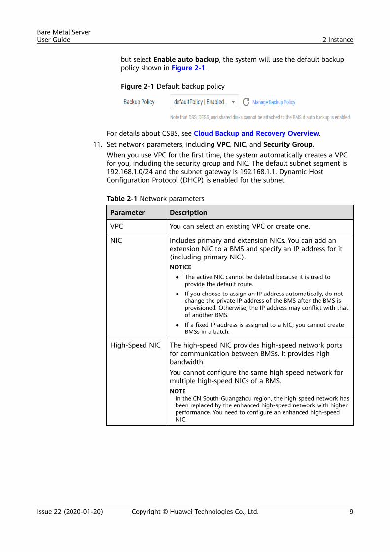
but select Enable auto backup, the system will use the default backuppolicy shown in Figure 2-1.
Figure 2-1 Default backup policy
For details about CSBS, see Cloud Backup and Recovery Overview.11. Set network parameters, including VPC, NIC, and Security Group.
When you use VPC for the first time, the system automatically creates a VPCfor you, including the security group and NIC. The default subnet segment is192.168.1.0/24 and the subnet gateway is 192.168.1.1. Dynamic HostConfiguration Protocol (DHCP) is enabled for the subnet.
Table 2-1 Network parameters
Parameter Description
VPC You can select an existing VPC or create one.
NIC Includes primary and extension NICs. You can add anextension NIC to a BMS and specify an IP address for it(including primary NIC).NOTICE
● The active NIC cannot be deleted because it is used toprovide the default route.
● If you choose to assign an IP address automatically, do notchange the private IP address of the BMS after the BMS isprovisioned. Otherwise, the IP address may conflict with thatof another BMS.
● If a fixed IP address is assigned to a NIC, you cannot createBMSs in a batch.
High-Speed NIC The high-speed NIC provides high-speed network portsfor communication between BMSs. It provides highbandwidth.You cannot configure the same high-speed network formultiple high-speed NICs of a BMS.NOTE
In the CN South-Guangzhou region, the high-speed network hasbeen replaced by the enhanced high-speed network with higherperformance. You need to configure an enhanced high-speedNIC.
Bare Metal ServerUser Guide 2 Instance
Issue 22 (2020-01-20) Copyright © Huawei Technologies Co., Ltd. 9
Parameter Description
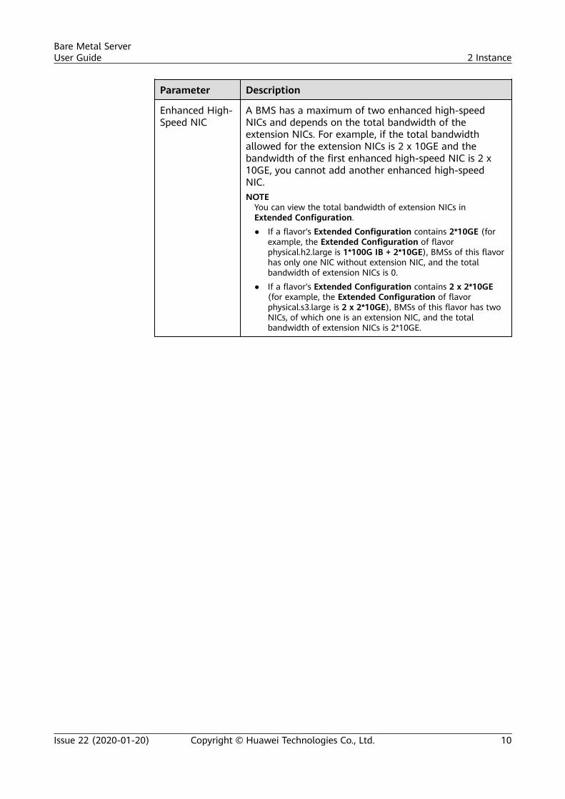
Enhanced High-Speed NIC
A BMS has a maximum of two enhanced high-speedNICs and depends on the total bandwidth of theextension NICs. For example, if the total bandwidthallowed for the extension NICs is 2 x 10GE and thebandwidth of the first enhanced high-speed NIC is 2 x10GE, you cannot add another enhanced high-speedNIC.NOTE
You can view the total bandwidth of extension NICs inExtended Configuration.● If a flavor's Extended Configuration contains 2*10GE (for
example, the Extended Configuration of flavorphysical.h2.large is 1*100G IB + 2*10GE), BMSs of this flavorhas only one NIC without extension NIC, and the totalbandwidth of extension NICs is 0.
● If a flavor's Extended Configuration contains 2 x 2*10GE(for example, the Extended Configuration of flavorphysical.s3.large is 2 x 2*10GE), BMSs of this flavor has twoNICs, of which one is an extension NIC, and the totalbandwidth of extension NICs is 2*10GE.
Bare Metal ServerUser Guide 2 Instance
Issue 22 (2020-01-20) Copyright © Huawei Technologies Co., Ltd. 10
Parameter Description
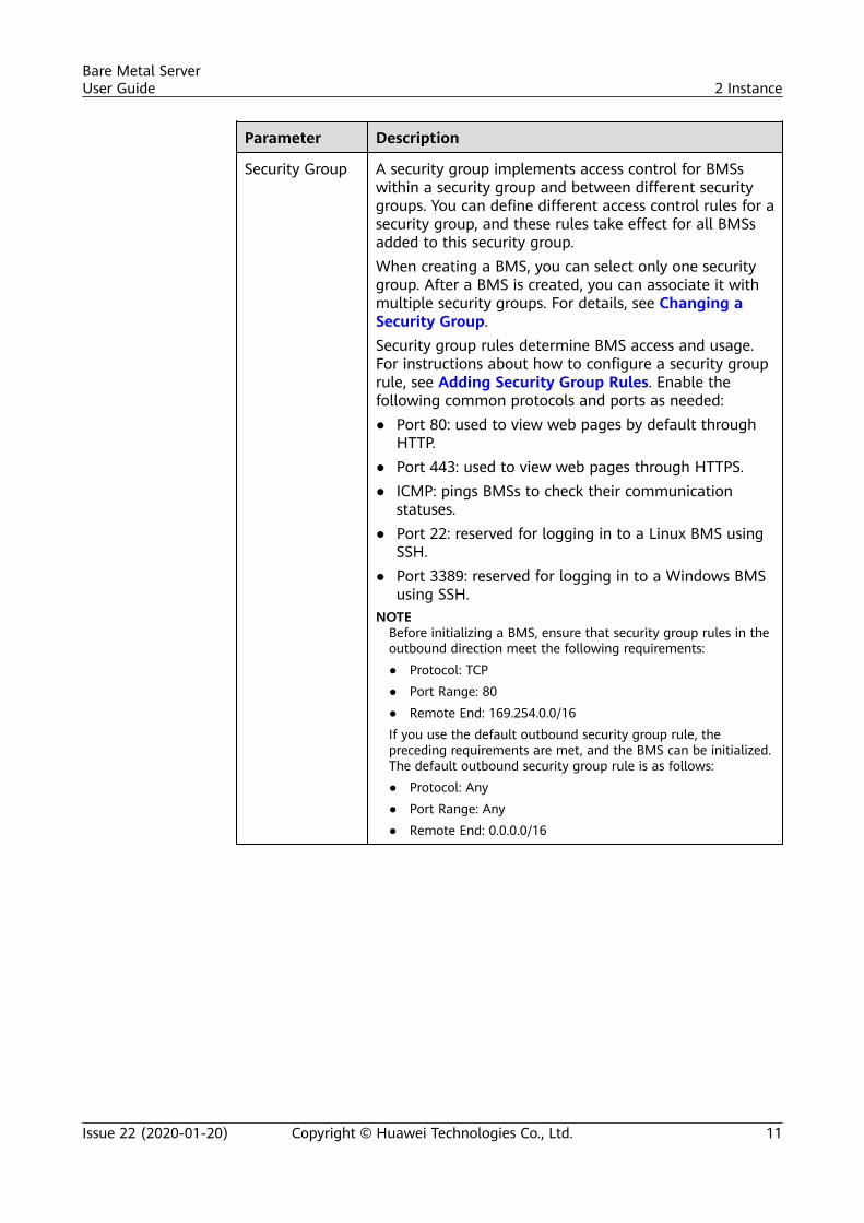
Security Group A security group implements access control for BMSswithin a security group and between different securitygroups. You can define different access control rules for asecurity group, and these rules take effect for all BMSsadded to this security group.When creating a BMS, you can select only one securitygroup. After a BMS is created, you can associate it withmultiple security groups. For details, see Changing aSecurity Group.Security group rules determine BMS access and usage.For instructions about how to configure a security grouprule, see Adding Security Group Rules. Enable thefollowing common protocols and ports as needed:● Port 80: used to view web pages by default through
HTTP.● Port 443: used to view web pages through HTTPS.● ICMP: pings BMSs to check their communication
statuses.● Port 22: reserved for logging in to a Linux BMS using
SSH.● Port 3389: reserved for logging in to a Windows BMS
using SSH.NOTE
Before initializing a BMS, ensure that security group rules in theoutbound direction meet the following requirements:● Protocol: TCP● Port Range: 80● Remote End: 169.254.0.0/16If you use the default outbound security group rule, thepreceding requirements are met, and the BMS can be initialized.The default outbound security group rule is as follows:● Protocol: Any● Port Range: Any● Remote End: 0.0.0.0/16
Bare Metal ServerUser Guide 2 Instance
Issue 22 (2020-01-20) Copyright © Huawei Technologies Co., Ltd. 11
Parameter Description
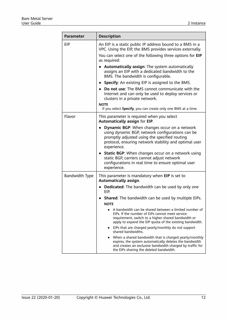
EIP An EIP is a static public IP address bound to a BMS in aVPC. Using the EIP, the BMS provides services externally.You can select one of the following three options for EIPas required:● Automatically assign: The system automatically
assigns an EIP with a dedicated bandwidth to theBMS. The bandwidth is configurable.
● Specify: An existing EIP is assigned to the BMS.● Do not use: The BMS cannot communicate with the
Internet and can only be used to deploy services orclusters in a private network.
NOTEIf you select Specify, you can create only one BMS at a time.
Flavor This parameter is required when you selectAutomatically assign for EIP.● Dynamic BGP: When changes occur on a network
using dynamic BGP, network configurations can bepromptly adjusted using the specified routingprotocol, ensuring network stability and optimal userexperience.
● Static BGP: When changes occur on a network usingstatic BGP, carriers cannot adjust networkconfigurations in real time to ensure optimal userexperience.
Bandwidth Type This parameter is mandatory when EIP is set toAutomatically assign.● Dedicated: The bandwidth can be used by only one
EIP.● Shared: The bandwidth can be used by multiple EIPs.
NOTE● A bandwidth can be shared between a limited number of
EIPs. If the number of EIPs cannot meet servicerequirement, switch to a higher shared bandwidth orapply to expand the EIP quota of the existing bandwidth.
● EIPs that are charged yearly/monthly do not supportshared bandwidths.
● When a shared bandwidth that is charged yearly/monthlyexpires, the system automatically deletes the bandwidthand creates an exclusive bandwidth charged by traffic forthe EIPs sharing the deleted bandwidth.
Bare Metal ServerUser Guide 2 Instance
Issue 22 (2020-01-20) Copyright © Huawei Technologies Co., Ltd. 12
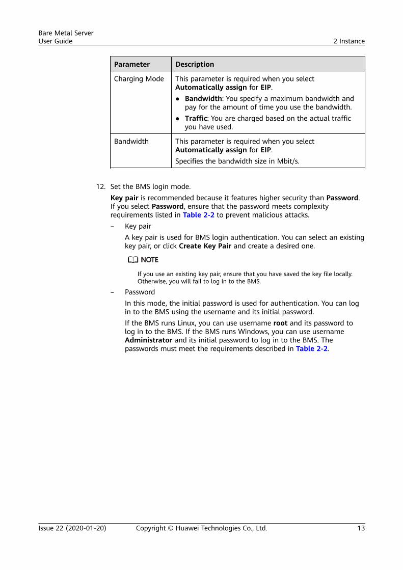
Parameter Description
Charging Mode This parameter is required when you selectAutomatically assign for EIP.● Bandwidth: You specify a maximum bandwidth and
pay for the amount of time you use the bandwidth.● Traffic: You are charged based on the actual traffic
you have used.
Bandwidth This parameter is required when you selectAutomatically assign for EIP.Specifies the bandwidth size in Mbit/s.
12. Set the BMS login mode.
Key pair is recommended because it features higher security than Password.If you select Password, ensure that the password meets complexityrequirements listed in Table 2-2 to prevent malicious attacks.– Key pair
A key pair is used for BMS login authentication. You can select an existingkey pair, or click Create Key Pair and create a desired one.
If you use an existing key pair, ensure that you have saved the key file locally.Otherwise, you will fail to log in to the BMS.
– PasswordIn this mode, the initial password is used for authentication. You can login to the BMS using the username and its initial password.If the BMS runs Linux, you can use username root and its password tolog in to the BMS. If the BMS runs Windows, you can use usernameAdministrator and its initial password to log in to the BMS. Thepasswords must meet the requirements described in Table 2-2.
Bare Metal ServerUser Guide 2 Instance
Issue 22 (2020-01-20) Copyright © Huawei Technologies Co., Ltd. 13
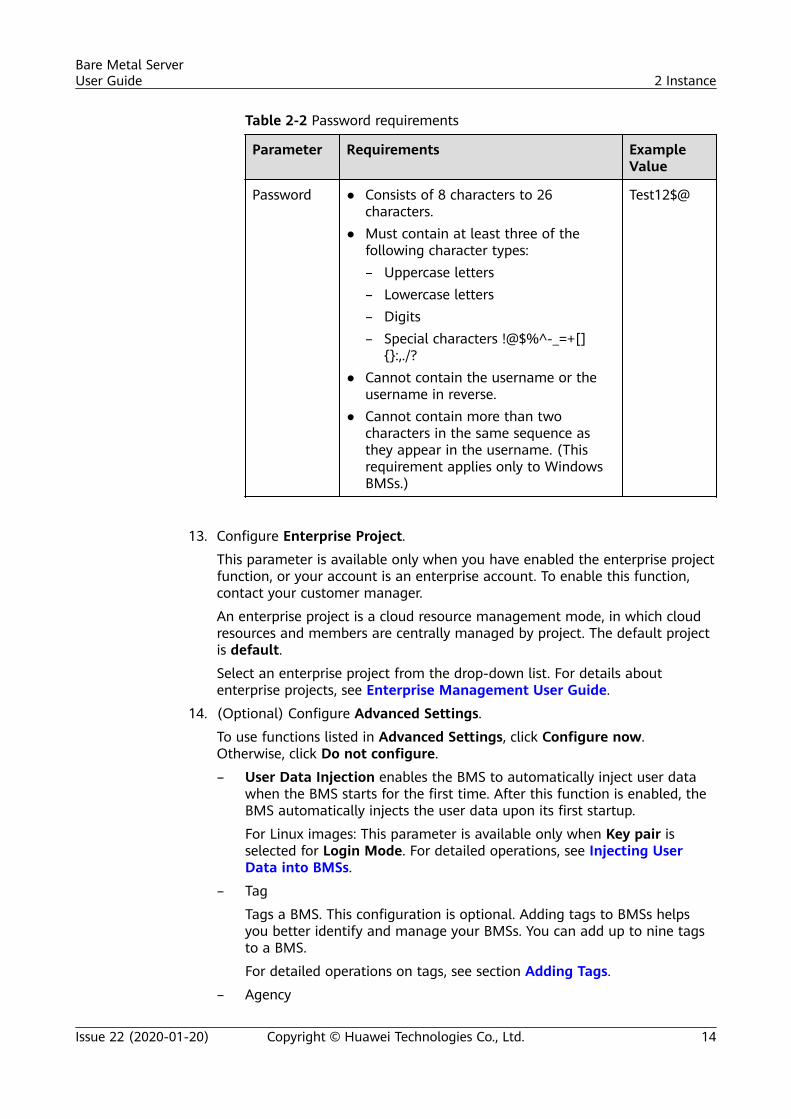
Table 2-2 Password requirements
Parameter Requirements ExampleValue
Password ● Consists of 8 characters to 26characters.
● Must contain at least three of thefollowing character types:– Uppercase letters– Lowercase letters– Digits– Special characters !@$%^-_=+[]
{}:,./?● Cannot contain the username or the
username in reverse.● Cannot contain more than two
characters in the same sequence asthey appear in the username. (Thisrequirement applies only to WindowsBMSs.)
Test12$@
13. Configure Enterprise Project.
This parameter is available only when you have enabled the enterprise projectfunction, or your account is an enterprise account. To enable this function,contact your customer manager.
An enterprise project is a cloud resource management mode, in which cloudresources and members are centrally managed by project. The default projectis default.
Select an enterprise project from the drop-down list. For details aboutenterprise projects, see Enterprise Management User Guide.
14. (Optional) Configure Advanced Settings.
To use functions listed in Advanced Settings, click Configure now.Otherwise, click Do not configure.
– User Data Injection enables the BMS to automatically inject user datawhen the BMS starts for the first time. After this function is enabled, theBMS automatically injects the user data upon its first startup.
For Linux images: This parameter is available only when Key pair isselected for Login Mode. For detailed operations, see Injecting UserData into BMSs.
– Tag
Tags a BMS. This configuration is optional. Adding tags to BMSs helpsyou better identify and manage your BMSs. You can add up to nine tagsto a BMS.
For detailed operations on tags, see section Adding Tags.
– Agency
Bare Metal ServerUser Guide 2 Instance
Issue 22 (2020-01-20) Copyright © Huawei Technologies Co., Ltd. 14
An agency provides BMSs with temporary security credentials foraccessing other cloud services. The agency is created by the tenantadministrator on the IAM console.
If you have created an agency in IAM, you can select the agency from thedrop-down list and obtain specified operation permissions. If you have noagency, click Create Agency to create one. Currently, agencies are mainlyused for server monitoring. For more information, see Overview.
15. Set BMS Name.
The name can be customized but can contain only letters, digits, underscores(_), hyphens (-), and periods (.).
If you buy multiple BMSs at a time, suffixes will be added to the BMSs insequence, such as bms-0001 and bms-0002. If you buy multiple BMSs again,the values in the new BMS names increase from the existing maximum value.For example, the existing BMS with the maximum number in name isbms-0010. If you enter bms, the names of the new BMSs will be bms-0011,bms-0012, .... When the value reaches 9999, it will start from 0001 again.
16. Set Required Duration and Quantity.
– Required Duration: Set the service duration if you select the Yearly/Monthly billing mode. The service duration ranges from one month toone year.
BMSs charged in yearly/monthly mode cannot be deleted. They support onlyresource unsubscription. If you no longer need a BMS, you can unsubscribe fromit using either of the following methods:
● Locate the row that contains the BMS, click More in the Operation column,and select Unsubscribe from the drop-down list. On the Unsubscribes page,click Unsubscribe.
● Choose Billing Center > Unsubscriptions and Changes > Unsubscriptions.Locate the row that contains the BMS, click More in the Operation column,and select Unsubscribe from the drop-down list.
– Purchase Quantity: 1 to 24
● If the quota is sufficient, you can buy a maximum of 24 BMSs. If the quota isless than 24, you can buy a maximum of all available BMSs.
● If you manually set an IP address for the user-defined NICs or high-speed NIC,or specify an EIP, you can buy only one BMS at a time.
17. Click Buy Now. If you have any question about the price, click Pricing details.
On the Order Details page, confirm the BMS information and click SubmitOrder.
18. Pay the fees as prompted and click OK.
The BMS console is displayed.
19. After you pay the order, the system will create your requested BMSs.
The BMS status changes to Running after about 30 minutes. If you select aflavor that supports quick provisioning, you can obtain a BMS in about fiveminutes.
Bare Metal ServerUser Guide 2 Instance
Issue 22 (2020-01-20) Copyright © Huawei Technologies Co., Ltd. 15
You can view the BMS creation status. For details, see Viewing BMS CreationStatuses.
Follow-up Operations● After the BMS is created, you can view its details, such as name/ID, disks, and
private IP address. For details, see Viewing BMS Details.● After logging in to the BMS, you can install software or deploy services as
needed. The login mode varies depending on the BMS OS. For details, seeLinux BMS Login Methods or Windows BMS Login Methods.
● If you have created data disks when creating the BMS, you must formatpartitions of the data disks. For details, see Introduction to Data DiskInitialization Scenarios and Partition Styles.
● Change the validity period of the password to prevent any inconveniencecaused by password expiration. For detailed operations, see How Do I Set thePassword Validity Period?
● BMSs created using public images have the one-click password reset plugin bydefault. If you BMS does not have the password reset plugin, or if you want tocheck whether the plugin is installed, see (Optional) Installing the One-Click Password Reset Plug-in.
● Some types of BMSs require drivers. For details about how to install drivers,see Installing the NVIDIA GPU Driver and CUDA Toolkit on a P1 BMS orInstalling the NVIDIA GPU Driver and CUDA Toolkit on a P2 BMS.
● Currently, Windows Server 2012 BMSs have the same security identifier (SID),which is used to identify users, groups, and computer accounts. In clusterdeployment scenarios, change the SIDs of BMSs by following the instructionsin How Do I Change the SID of a Windows Server 2012 BMS? to ensurethat each BMS has a unique SID.
2.1.2 Creating a BMS Supporting Quick Provisioning
Scenarios
When provisioning a common BMS, you need to download its OS from the cloudand install it. The download costs a long time. BMSs using EVS disks as systemdisks can be provisioned quickly.
BMSs supporting quick provisioning have the following advantages over otherBMSs:
● BMSs booted from EVS disks can be provisioned within about 5 minutes.● BMSs support CSBS backups, ensuring data security.● BMS rebuilding upon faults is supported, enabling quick service recovery.● An Image of a BMS can be exported to apply configurations of the BMS to
other BMSs without the need of configuring the BMSs again.
On the page for creating a BMS, select a flavor that supports quick BMSprovisioning, set the system disk type and capacity, and configure other requiredparameters to obtain a BMS.
Bare Metal ServerUser Guide 2 Instance
Issue 22 (2020-01-20) Copyright © Huawei Technologies Co., Ltd. 16
Procedure
You can create a BMS supporting quick provisioning by following the instructionsin Creating a BMS.
When creating the BMS, pay attention to the following parameters:
● Flavor: Select physical.s4.medium, physical.s4.large, physical.s4.xlarge,physical.s4.2xlarge, or physical.s4.3xlarge. For more information aboutflavors, see Instance Family.
● Image: Select a public image that supports quick provisioning.● Disk: Set the system disk type and size.● Auto Backup: You are advised to select Enable auto backup and set Backup
Policy to ensure data security.
2.1.3 Creating a Dedicated BMS
Scenarios
Resources in a DeC are physically isolated from those in public resource pools. Ifyour services have high security compliance requirements, you can create BMSs ina DeC in either of the following ways:
● Create a BMS on the DeC Console● Create a BMS on the Cloud Server Console
Before creating a BMS in a DeC, you must apply for a dedicated BMS resourcepool.
Prerequisites
You have enabled DeC. For details, see Enabling a DeC.
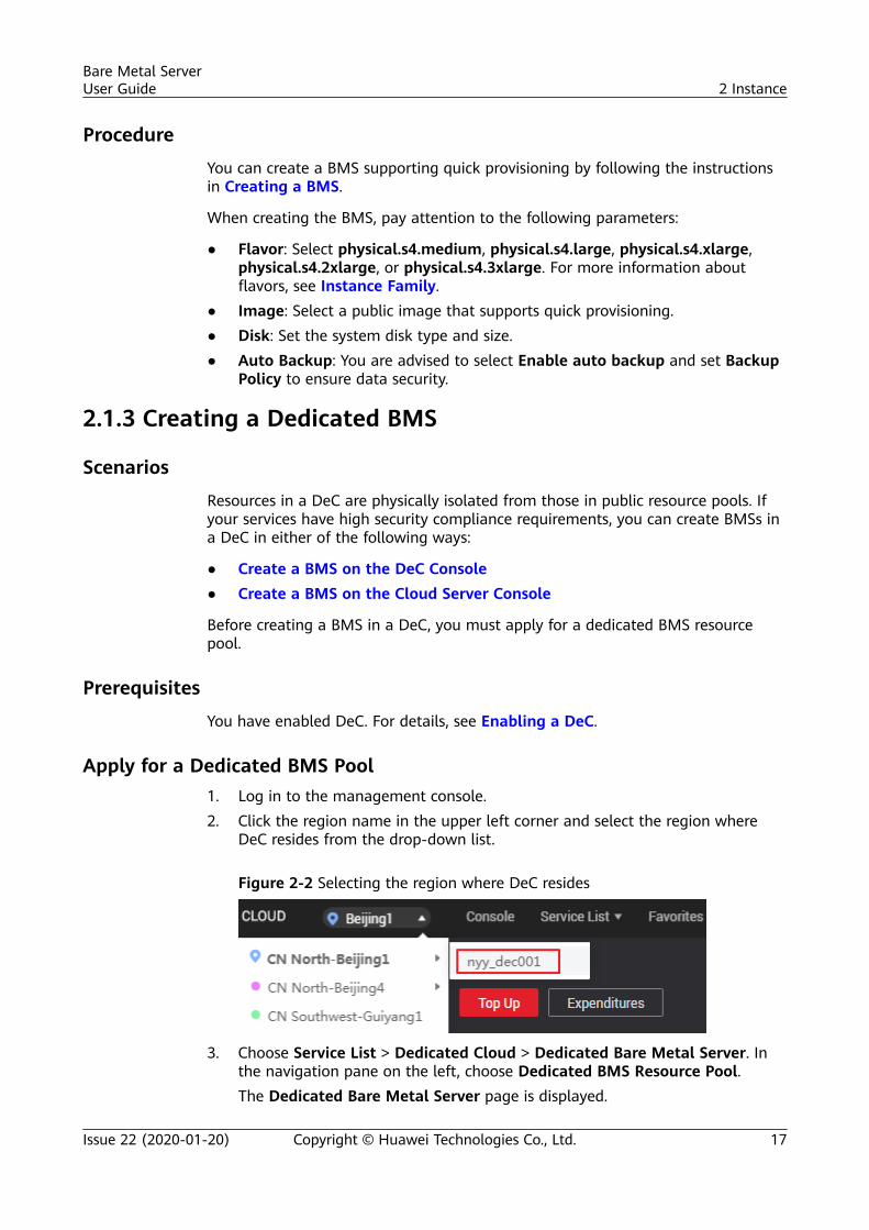
Apply for a Dedicated BMS Pool1. Log in to the management console.2. Click the region name in the upper left corner and select the region where
DeC resides from the drop-down list.
Figure 2-2 Selecting the region where DeC resides
3. Choose Service List > Dedicated Cloud > Dedicated Bare Metal Server. Inthe navigation pane on the left, choose Dedicated BMS Resource Pool.The Dedicated Bare Metal Server page is displayed.
Bare Metal ServerUser Guide 2 Instance
Issue 22 (2020-01-20) Copyright © Huawei Technologies Co., Ltd. 17
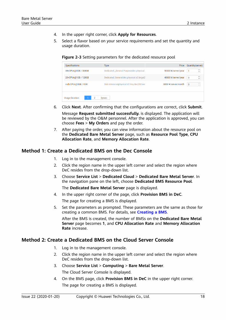
4. In the upper right corner, click Apply for Resources.5. Select a flavor based on your service requirements and set the quantity and
usage duration.
Figure 2-3 Setting parameters for the dedicated resource pool
6. Click Next. After confirming that the configurations are correct, click Submit.Message Request submitted successfully. is displayed. The application willbe reviewed by the O&M personnel. After the application is approved, you canchoose Fees > My Orders and pay the order.
7. After paying the order, you can view information about the resource pool onthe Dedicated Bare Metal Server page, such as Resource Pool Type, CPUAllocation Rate, and Memory Allocation Rate.
Method 1: Create a Dedicated BMS on the Dec Console1. Log in to the management console.2. Click the region name in the upper left corner and select the region where
DeC resides from the drop-down list.3. Choose Service List > Dedicated Cloud > Dedicated Bare Metal Server. In
the navigation pane on the left, choose Dedicated BMS Resource Pool.The Dedicated Bare Metal Server page is displayed.
4. In the upper right corner of the page, click Provision BMS in DeC.The page for creating a BMS is displayed.
5. Set the parameters as prompted. These parameters are the same as those forcreating a common BMS. For details, see Creating a BMS.After the BMS is created, the number of BMSs on the Dedicated Bare MetalServer page becomes 1, and CPU Allocation Rate and Memory AllocationRate increase.
Method 2: Create a Dedicated BMS on the Cloud Server Console1. Log in to the management console.2. Click the region name in the upper left corner and select the region where
DeC resides from the drop-down list.3. Choose Service List > Computing > Bare Metal Server.
The Cloud Server Console is displayed.4. On the BMS page, click Provision BMS in DeC in the upper right corner.
The page for creating a BMS is displayed.
Bare Metal ServerUser Guide 2 Instance
Issue 22 (2020-01-20) Copyright © Huawei Technologies Co., Ltd. 18
5. Set the parameters as prompted. These parameters are the same as those forcreating a common BMS. For details, see Creating a BMS.After the BMS is displayed, click the BMS Resource Pool tab in the ResourceUsage Details area on the Dashboard page. The number of BMSs is 1, andCPU Allocation Rate and Memory Allocation Rate increase.
2.1.4 Creating a BMS Using a Private Image
ScenariosIf you want to create a BMS that has the same OS and applications as an existingBMS, you can create a private image using the existing BMS and then create aBMS using the private image. This frees you from repeatedly configuring BMSsand improves efficiency.
Background● If the private image belongs to the same region as the BMS you want to
create, create the private image using either of the following methods:– Creating a Private Image from a BMS– Creating a Private Image from an External Image File
● If the private image belongs to a region different from the BMS you want tocreate, replicate the image to the region where you want to create the BMS.For details, see Replicating Images Across Regions.
● If the private image belongs to another tenant, you must have the tenantshare the image with you. For details, see Sharing Specified Images.
ProcedureCreate a BMS by following the instructions in Creating a BMS.
Note for setting the parameters:
● Region: Select the region where the private image is located.● Flavor: OSs supported by different BMS flavors vary. For details, see OSs
Supported by Different Types of BMSs. Select a flavor based on the privateimage OS.
● Image: Select Private image or Shared image and select the required imagefrom the drop-down list.
● Disk: If the selected flavor supports quick provisioning, you are advised toincrease System Disk by 2 GB or more.
2.2 Viewing BMS Information
Bare Metal ServerUser Guide 2 Instance
Issue 22 (2020-01-20) Copyright © Huawei Technologies Co., Ltd. 19
2.2.1 Viewing BMS Creation Statuses
ScenariosAfter clicking Submit to request a BMS, you can query the task status in the TaskStatus area. A task involves several sub-tasks, such as creating a BMS resource,binding an EIP, and attaching an EVS disk.
The task status may be either Creating or Failed:
● Processing: The system is processing the task.● Failed: The system has failed to process the task. The system rolls back the
failed task and displays an error code, for example, (BMS.3033) Failed tocreate system disk.
This section describes how to query BMS application processing status and theinformation displayed in the Task Status area.
Procedure1. Log in to the management console.2. Under Computing, click Bare Metal Server.
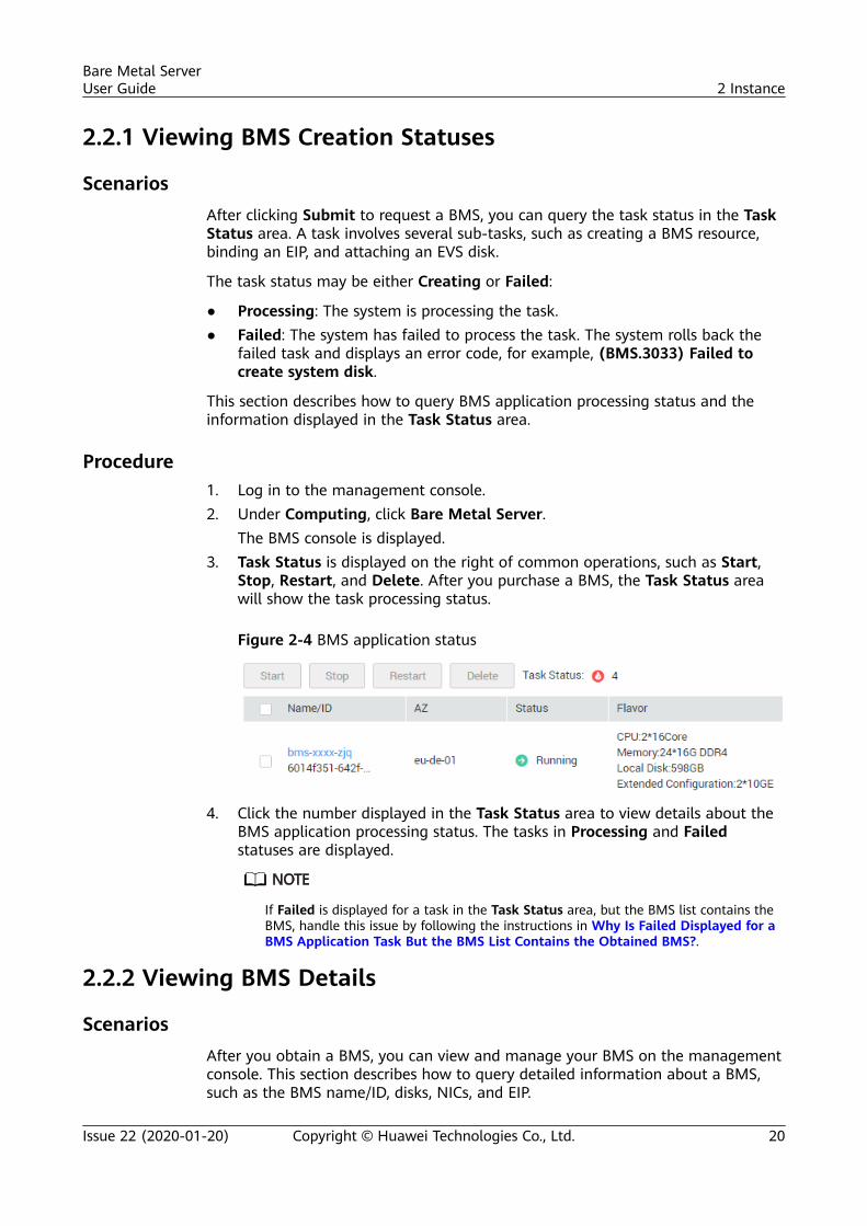
The BMS console is displayed.3. Task Status is displayed on the right of common operations, such as Start,
Stop, Restart, and Delete. After you purchase a BMS, the Task Status areawill show the task processing status.
Figure 2-4 BMS application status
4. Click the number displayed in the Task Status area to view details about theBMS application processing status. The tasks in Processing and Failedstatuses are displayed.
If Failed is displayed for a task in the Task Status area, but the BMS list contains theBMS, handle this issue by following the instructions in Why Is Failed Displayed for aBMS Application Task But the BMS List Contains the Obtained BMS?.
2.2.2 Viewing BMS Details
ScenariosAfter you obtain a BMS, you can view and manage your BMS on the managementconsole. This section describes how to query detailed information about a BMS,such as the BMS name/ID, disks, NICs, and EIP.
Bare Metal ServerUser Guide 2 Instance
Issue 22 (2020-01-20) Copyright © Huawei Technologies Co., Ltd. 20
Procedure1. Log in to the management console.2. Under Computing, click Bare Metal Server.
On the BMS list page, you can view your BMS and its flavor, image, andprivate IP address.
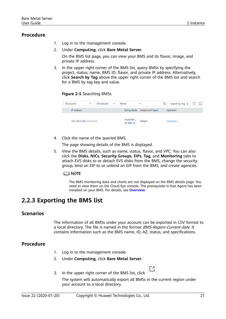
3. In the upper right corner of the BMS list, query BMSs by specifying theproject, status, name, BMS ID, flavor, and private IP address. Alternatively,click Search by Tag above the upper right corner of the BMS list and searchfor a BMS by tag key and value.
Figure 2-5 Searching BMSs
4. Click the name of the queried BMS.The page showing details of the BMS is displayed.
5. View the BMS details, such as name, status, flavor, and VPC. You can alsoclick the Disks, NICs, Security Groups, EIPs, Tag, and Monitoring tabs toattach EVS disks to or detach EVS disks from the BMS, change the securitygroup, bind an EIP to or unbind an EIP from the BMS, and create agencies.
The BMS monitoring data and charts are not displayed on the BMS details page. Youneed to view them on the Cloud Eye console. The prerequisite is that Agent has beeninstalled on your BMS. For details, see Overview.
2.2.3 Exporting the BMS list
Scenarios
The information of all BMSs under your account can be exported in CSV format toa local directory. The file is named in the format BMS-Region-Current date. Itcontains information such as the BMS name, ID, AZ, status, and specifications.
Procedure1. Log in to the management console.2. Under Computing, click Bare Metal Server.
3. In the upper right corner of the BMS list, click .The system will automatically export all BMSs in the current region underyour account to a local directory.
Bare Metal ServerUser Guide 2 Instance
Issue 22 (2020-01-20) Copyright © Huawei Technologies Co., Ltd. 21
2.3 Logging In to a Linux BMS
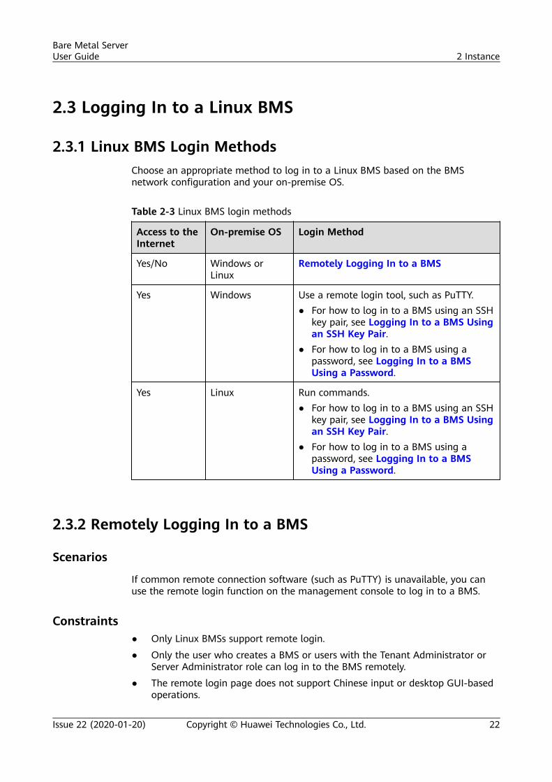
2.3.1 Linux BMS Login MethodsChoose an appropriate method to log in to a Linux BMS based on the BMSnetwork configuration and your on-premise OS.
Table 2-3 Linux BMS login methods
Access to theInternet
On-premise OS Login Method
Yes/No Windows orLinux
Remotely Logging In to a BMS
Yes Windows Use a remote login tool, such as PuTTY.● For how to log in to a BMS using an SSH
key pair, see Logging In to a BMS Usingan SSH Key Pair.
● For how to log in to a BMS using apassword, see Logging In to a BMSUsing a Password.
Yes Linux Run commands.● For how to log in to a BMS using an SSH
key pair, see Logging In to a BMS Usingan SSH Key Pair.
● For how to log in to a BMS using apassword, see Logging In to a BMSUsing a Password.
2.3.2 Remotely Logging In to a BMS
Scenarios
If common remote connection software (such as PuTTY) is unavailable, you canuse the remote login function on the management console to log in to a BMS.
Constraints● Only Linux BMSs support remote login.
● Only the user who creates a BMS or users with the Tenant Administrator orServer Administrator role can log in to the BMS remotely.
● The remote login page does not support Chinese input or desktop GUI-basedoperations.
Bare Metal ServerUser Guide 2 Instance
Issue 22 (2020-01-20) Copyright © Huawei Technologies Co., Ltd. 22
● When you log in to a BMS remotely, shortcut keys such as Ctrl and Alt are notwell supported. For example, if you enter Alt + ASCII code, multiple specialcharacters are displayed.
● Before exiting the management console, log out of the OS.
Prerequisites● The BMS must be in Running state.
● You have set a login password when creating the BMS. If you did not set apassword or forget the password, you can reset the password by following theinstructions in Resetting the BMS Password with a Few Clicks.
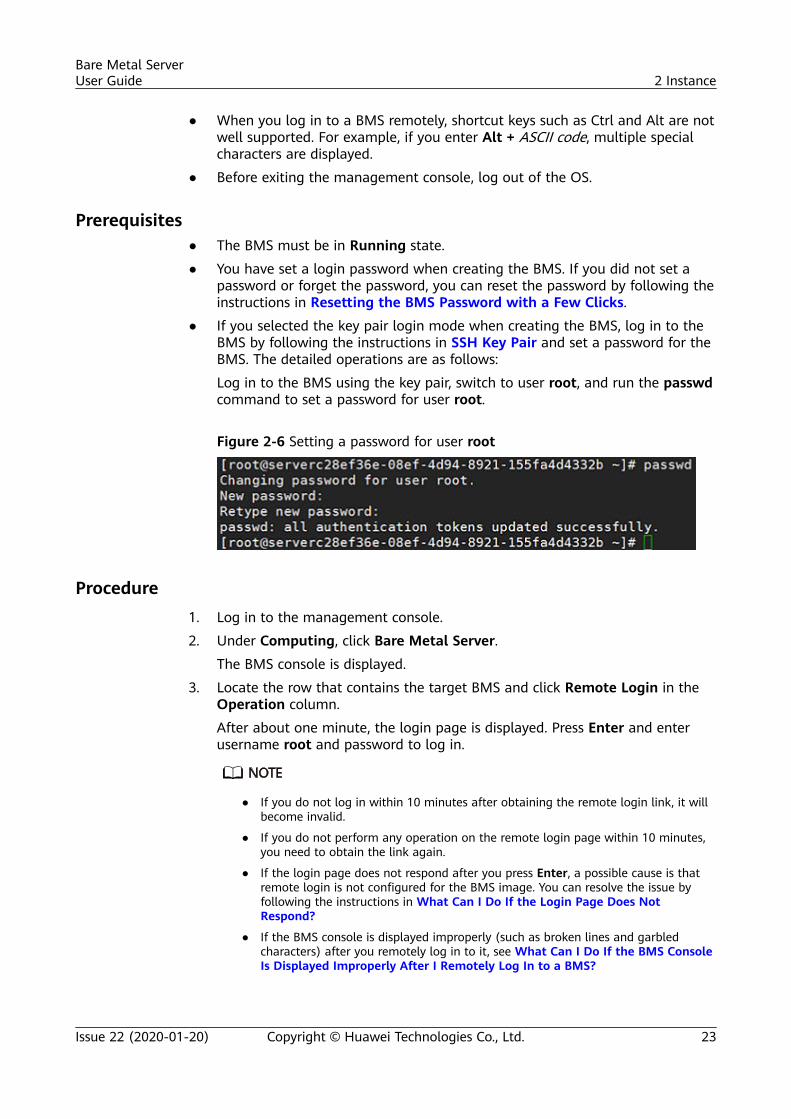
● If you selected the key pair login mode when creating the BMS, log in to theBMS by following the instructions in SSH Key Pair and set a password for theBMS. The detailed operations are as follows:
Log in to the BMS using the key pair, switch to user root, and run the passwdcommand to set a password for user root.
Figure 2-6 Setting a password for user root
Procedure1. Log in to the management console.
2. Under Computing, click Bare Metal Server.
The BMS console is displayed.
3. Locate the row that contains the target BMS and click Remote Login in theOperation column.
After about one minute, the login page is displayed. Press Enter and enterusername root and password to log in.
● If you do not log in within 10 minutes after obtaining the remote login link, it willbecome invalid.
● If you do not perform any operation on the remote login page within 10 minutes,you need to obtain the link again.
● If the login page does not respond after you press Enter, a possible cause is thatremote login is not configured for the BMS image. You can resolve the issue byfollowing the instructions in What Can I Do If the Login Page Does NotRespond?
● If the BMS console is displayed improperly (such as broken lines and garbledcharacters) after you remotely log in to it, see What Can I Do If the BMS ConsoleIs Displayed Improperly After I Remotely Log In to a BMS?
Bare Metal ServerUser Guide 2 Instance
Issue 22 (2020-01-20) Copyright © Huawei Technologies Co., Ltd. 23
2.3.3 Logging In to a BMS Using an SSH Key Pair
Prerequisites● The BMS must be in Running state.● You have obtained the private key file used during BMS creation.● You have bound an EIP to the BMS. For details, see Binding an EIP to a BMS.● You have configured the inbound rules of the security group. For details, see
section Adding Security Group Rules.● The network connection between the login tool (such as PuTTY) and the
target BMS is normal. For example, the default port 22 is not blocked by thefirewall.
Logging In to the Linux BMS from a Windows ComputerYou can use the following methods to log in to a Linux BMS from a local PCrunning Windows:
Method 1: Use PuTTY to log in to the BMS.
Before logging in to the BMS using PuTTY, ensure that the private key file hasbeen converted to .ppk format.
1. Check whether the private key file has been converted to .ppk format.– If yes, go to step 7.– If no, go to step 2.
2. Visit the following website and download PuTTY and PuTTYgen:https://www.chiark.greenend.org.uk/~sgtatham/putty/latest.html
PuTTYgen is a private key generator, which is used to create a key pair that consists ofa public key and a private key for PuTTY.
3. Run PuTTYgen.4. In the Actions area, click Load and import the private key file that you stored
when creating the BMS.Ensure that the private key file is in the format of All files (*.*).
5. Click Save private key.6. Save the converted private key to the local PC, for example, kp-123.ppk, to
the local computer.7. Double-click PUTTY.EXE. The PuTTY Configuration page is displayed.
Bare Metal ServerUser Guide 2 Instance
Issue 22 (2020-01-20) Copyright © Huawei Technologies Co., Ltd. 24
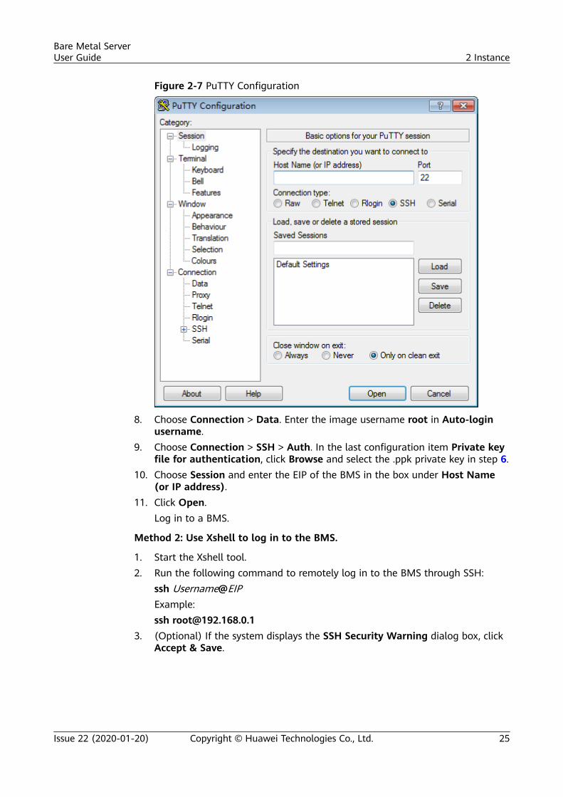
Figure 2-7 PuTTY Configuration
8. Choose Connection > Data. Enter the image username root in Auto-loginusername.
9. Choose Connection > SSH > Auth. In the last configuration item Private keyfile for authentication, click Browse and select the .ppk private key in step 6.
10. Choose Session and enter the EIP of the BMS in the box under Host Name(or IP address).
11. Click Open.Log in to a BMS.
Method 2: Use Xshell to log in to the BMS.
1. Start the Xshell tool.2. Run the following command to remotely log in to the BMS through SSH:
ssh Username@EIPExample:ssh [email protected]
3. (Optional) If the system displays the SSH Security Warning dialog box, clickAccept & Save.
Bare Metal ServerUser Guide 2 Instance
Issue 22 (2020-01-20) Copyright © Huawei Technologies Co., Ltd. 25
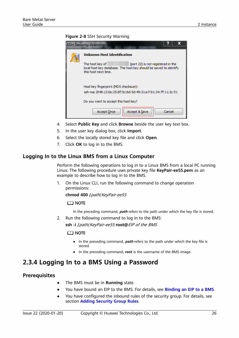
Figure 2-8 SSH Security Warning
4. Select Public Key and click Browse beside the user key text box.5. In the user key dialog box, click Import.6. Select the locally stored key file and click Open.7. Click OK to log in to the BMS.
Logging In to the Linux BMS from a Linux ComputerPerform the following operations to log in to a Linux BMS from a local PC runningLinux: The following procedure uses private key file KeyPair-ee55.pem as anexample to describe how to log in to the BMS.
1. On the Linux CLI, run the following command to change operationpermissions:chmod 400 /path/KeyPair-ee55
In the preceding command, path refers to the path under which the key file is stored.
2. Run the following command to log in to the BMS:ssh -i /path/KeyPair-ee55 root@EIP of the BMS
● In the preceding command, path refers to the path under which the key file isstored.
● In the preceding command, root is the username of the BMS image.
2.3.4 Logging In to a BMS Using a Password
Prerequisites● The BMS must be in Running state.● You have bound an EIP to the BMS. For details, see Binding an EIP to a BMS.● You have configured the inbound rules of the security group. For details, see
section Adding Security Group Rules.
Bare Metal ServerUser Guide 2 Instance
Issue 22 (2020-01-20) Copyright © Huawei Technologies Co., Ltd. 26
● The network connection between the login tool (such as PuTTY) and thetarget BMS is normal. For example, the default port 22 is not blocked by thefirewall.
If you want to use a password to log in a Linux BMS, log in to the BMS remotely byfollowing the instructions in Remotely Logging In to a BMS and enable the SSH passwordlogin mode. For details, see How Should I Set SSH Configuration Items?
Log In to a BMS from a Windows PC
You can use the following methods to log in to a Linux BMS from a local PCrunning Windows (for example, use PuTTY):
Download PuTTY from https://www.chiark.greenend.org.uk/~sgtatham/putty/latest.html.
1. Run PuTTY.2. In the navigation pane on the left, choose Session, enter the EIP of the BMS
in the text box under Host Name (or IP address), and select SSH forConnection type.
3. Choose Windows > Translation and select UTF-8 from the Received dataassumed to be in which character set: drop-down list box.
4. Click Open.5. Enter username root and the password you set to log in to the BMS.
Log In to a BMS from a Linux PC
To log in to a Linux BMS from a Linux PC, run the following command:
ssh EIP of the BMS
2.4 Logging In to a Windows BMS
2.4.1 Windows BMS Login MethodsCurrently, you can only log in to a Windows BMS remotely by running MSTSC onyour local PC. An EIP must be bound to the BMS.
2.4.2 Logging In to a BMS Remotely Using MSTSC
Prerequisites● The BMS must be in Running state.● If a Windows BMS uses the key pair authentication mode, you have obtained
the password for logging in to the BMS. For details, see Obtaining thePassword of a Windows BMS.
● You have bound an EIP to the BMS. For details, see Binding an EIP to a BMS.
Bare Metal ServerUser Guide 2 Instance
Issue 22 (2020-01-20) Copyright © Huawei Technologies Co., Ltd. 27
● You have configured the inbound rules of the security group. For details, seeAdding Security Group Rules.
● The network connection between the login tool and the target BMS is normal.For example, the default port 3389 is not blocked by the firewall.
Procedure
The following procedure describes how to log in to a Windows BMS usingmstsc.exe.
1. On the local PC, click Start.2. In the Search programs and files box, enter mstsc.exe and press Enter.3. Enter the EIP and username of the Windows BMS, click Connect, enter the
password as prompted, and click OK to log in to the BMS.
2.5 Managing BMSs
2.5.1 Changing the Name of a BMS
Scenarios
To make it easy for you to identify and manage each BMS, HUAWEI CLOUDallows you to set BMS names and change the names at any time. The new nameof a BMS takes effect after the BMS is restarted.
Constraints
The names of Windows BMSs cannot be changed.
Procedure1. Log in to the management console.2. Under Computing, click Bare Metal Server.
The BMS console is displayed.3. Click the name of the BMS whose name is to be changed.
4. Click next to Name, enter a new name that meets requirements, and click
to save the change.The BMS name can contain only letters, digits, hyphens (-), underscores (_),and periods (.).
5. Log in to the BMS OS and run the following command to enable automatichostname synchronization:vi /opt/huawei/network_config/bms-network-config.confSet the value of auto_synchronize_hostname to True.auto_synchronize_hostname = True
Press Esc and enter :wq to save and exit the file.
Bare Metal ServerUser Guide 2 Instance
Issue 22 (2020-01-20) Copyright © Huawei Technologies Co., Ltd. 28
If the value of auto_synchronize_hostname is False, after the BMS is restarted, thehostname will be automatically changed to that set during BMS creation.
6. Log in to the management console again. Locate the row that contains theBMS, click More in the Operation column, and select Restart.After about 10 minutes, verify that the BMS is restarted and its hostname isautomatically updated.
2.5.2 Resetting the BMS Password
ScenariosIf you forget the password for logging in to a BMS or if you want to harden thepassword to improve security, you can reset the password on the console.
NO TICE
If you change the password of a running BMS on the console, the BMS will beautomatically restarted during password resetting. To prevent data loss, it isrecommended that you reset the password during off-peak hours to minimize theimpact on your services.
Prerequisites● The password resetting function depends on the CloudResetPwdAgent plug-
in, which is installed for public images by default. If your BMS is created froma private image, check whether the plug-in has been installed by followingthe instructions in (Optional) Installing the One-Click Password ResetPlug-in.
● Ensure that DHCP is enabled in the VPC to which the BMS belongs.● The BMS network connectivity is normal.● An EIP has been bound to the BMS.
Procedure1. Log in to the management console.2. Under Computing, click Bare Metal Server.
The BMS console is displayed.3. Locate the row that contains the target BMS, click More in the Operation
column, and select Reset Password from the drop-down list.4. Set and confirm a new password as prompted.
Bare Metal ServerUser Guide 2 Instance
Issue 22 (2020-01-20) Copyright © Huawei Technologies Co., Ltd. 29
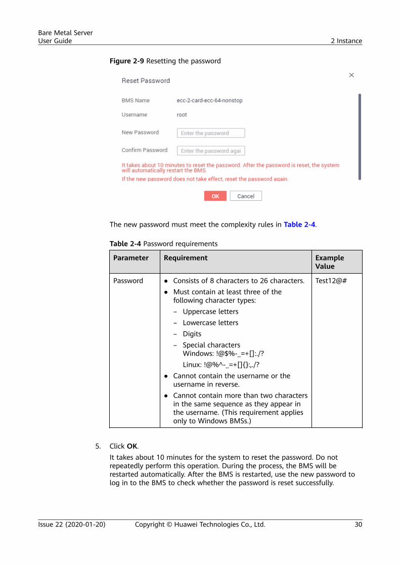
Figure 2-9 Resetting the password
The new password must meet the complexity rules in Table 2-4.
Table 2-4 Password requirements
Parameter Requirement ExampleValue
Password ● Consists of 8 characters to 26 characters.● Must contain at least three of the
following character types:– Uppercase letters– Lowercase letters– Digits– Special characters
Windows: !@$%-_=+[]:./?Linux: !@%^-_=+[]{}:,./?
● Cannot contain the username or theusername in reverse.
● Cannot contain more than two charactersin the same sequence as they appear inthe username. (This requirement appliesonly to Windows BMSs.)
Test12@#
5. Click OK.
It takes about 10 minutes for the system to reset the password. Do notrepeatedly perform this operation. During the process, the BMS will berestarted automatically. After the BMS is restarted, use the new password tolog in to the BMS to check whether the password is reset successfully.
Bare Metal ServerUser Guide 2 Instance
Issue 22 (2020-01-20) Copyright © Huawei Technologies Co., Ltd. 30
Related OperationsYou can reset the BMS password using an API. For details, see Resetting the BMSPassword by a Few Clicks.
You can also change the login password in the BMS OS. After changing thepassword, you must restart the BMS on the management console to make thenew password take effect. It is recommended that you change the password onthe console.
Helpful LinksWhat Should I Do If a Service Port Is Used by a One-Click Password ResetPlug-in?
2.5.3 Stopping BMSs
ScenariosYou can stop BMSs in Running state.
Stopping a BMS charged in yearly/monthly mode does not affect the BMS fees. Ifother service products, such as EVS disks, EIPs, and bandwidths are bound to theBMS, these products are billed using their own billing mode (yearly/monthly orpay-per-use).
If you choose to forcibly stop a BMS, services running on the BMS will be stopped. Beforeperforming this operation, ensure that you have saved files on the BMS.
Procedure1. Log in to the management console.2. Under Computing, click Bare Metal Server.
The BMS console is displayed.3. Locate the row that contains the target BMS, click More in the Operation
column, and select Stop from the drop-down list. To stop multiple BMSs,select them and click Stop at the top of the BMS list.
4. In the displayed dialog box, click Yes.
After a BMS is stopped, its status becomes Stopped.
You can perform the following operations only when the BMS is stopped:
● Detaching the System Disk● Creating an Image● Rebuilding a BMS
2.5.4 Restarting BMSs
ScenariosYou can restart BMSs on the console. Only BMSs in running state can be restarted.
Bare Metal ServerUser Guide 2 Instance
Issue 22 (2020-01-20) Copyright © Huawei Technologies Co., Ltd. 31
Restarting a BMS will interrupt your services. Exercise caution when performing thisoperation.
Procedure1. Log in to the management console.2. Under Computing, click Bare Metal Server.
The BMS console is displayed.3. Locate the row that contains the target BMS, click More in the Operation
column, and select Restart from the drop-down list. To restart multiple BMSs,select them and click Restart at the top of the BMS list.
4. In the displayed dialog box, click Yes.
2.5.5 Reinstalling the OS
ScenariosIf the OS of a BMS fails to start, suffer from viruses, or requires optimization,reinstall the OS.
The original image is used to reinstall the BMS OS. BMSs provisioned on localdisks and quickly provisioned BMSs both support OS reinstallation.
After the OS is reinstalled:
● The system disk type of the quickly provisioned BMS does not change.● The IP address and MAC address of the BMS do not change.
PrecautionsReinstalling the OS is a mission-critical operation. Before performing thisoperation, read the following precautions carefully:
● To reinstall the OS, you must stop the BMS, which will interrupt your services.● Reinstalling the OS clears the data in all partitions of the system disk. Back up
data before performing this operation.● Do not power off or restart the BMS during the OS reinstallation. Otherwise,
the reinstallation may fail.● After the OS is reinstalled, custom configurations, such as DNS and hostname
of the original OS will be reset. You must reconfigure the OS.
Constraints● The reinstalled OS must be the same as the original OS.● During the OS reinstallation, the system disk capacity of a BMS provisioned
using a local disk is not displayed.● If the EVS disk where the BMS OS is installed is deleted during the OS
reinstallation, the reinstallation will fail.● During the OS reinstallation, you cannot inject user data.
Bare Metal ServerUser Guide 2 Instance
Issue 22 (2020-01-20) Copyright © Huawei Technologies Co., Ltd. 32
● The OS of a BMS in maintenance state cannot be reinstalled.
Prerequisites● The target BMS must be in Stopped or Reinstalling OS failed state.● If the boot device of the BMS is the EVS disk, the EVS disk quota must be
greater than 0.● The target BMS that supports quick provisioning has a system disk.● If the target BMS is created using a private image, ensure that the image is
still available.● The OS reinstallation depends on the bms-network-config and Cloud-Init
plug-ins in the BMS image.– If the target BMS uses a public image, ensure that the image has the
bms-network-config and Cloud-Init plug-ins.– If the BMS uses a private image, check whether bms-network-config and
Cloud-Init are installed by following the instructions in Bare Metal ServerPrivate Image Creation Guide.
Procedure1. Log in to the management console.2. Under Computing, click Bare Metal Server.
The BMS console is displayed.3. Locate the row containing the target BMS, click More in the Operation
column, and select Reinstall OS from the drop-down list.The Reinstall OS dialog box is displayed.
Figure 2-10 Reinstalling the BMS OS
4. Set Login Mode.– Key pair: You can select an existing key pair or click Create Key Pair and
create a private key used to log in to the BMS.
Bare Metal ServerUser Guide 2 Instance
Issue 22 (2020-01-20) Copyright © Huawei Technologies Co., Ltd. 33

– Password: You can set the initial password for logging in to the BMS OS.The new password must meet the password complexity requirementslisted in Table 2-7.
5. Click OK.6. On the BMS OS Reinstallation page, confirm the OS configuration and click
Submit.After the application is submitted, the BMS status changes to ReinstallingOS. The reinstallation is complete when the BMS status changes to Running.After the OS is reinstalled, the BMS will start automatically.
Do not perform any operation on the temporary BMS during the reinstallation process.
Follow-up OperationsIf the QinQ network has been configured for the BMS before the OS reinstallation,configure the network by following the instructions in sections Configuring aUser-defined VLAN (SUSE Linux Enterprise Server 12) to Configuring a User-defined VLAN (Windows Server) after the OS is reinstalled.
2.5.6 Rebuilding a BMS
ScenariosIf the BMS cannot work properly due to hardware or SDI card damage, you canrebuild the BMS. This section describes how to rebuild a BMS.
The BMS is not automatically rebuilt. You need to contact the administrator to have yourBMS rebuilt.
Notes● Currently, only BMSs that are quickly provisioned can be rebuilt.● After a BMS is rebuilt, it will start automatically.● If the BMS uses an IB NIC, record the IP address of the IB NIC rebuilding the
BMS.● If the BMS uses a QinQ network, record the IP address of the QinQ network
before rebuilding the BMS.
Restrictions and Limitations● A BMS can only be rebuilt in the same POD.● A BMS to be rebuilt must use an EVS disk as its system disk.● Data on local disks cannot be migrated after a BMS is rebuilt.
Prerequisites● The BMS to be rebuilt must be stopped.● The BMS to be rebuilt must have a system disk.
Bare Metal ServerUser Guide 2 Instance
Issue 22 (2020-01-20) Copyright © Huawei Technologies Co., Ltd. 34
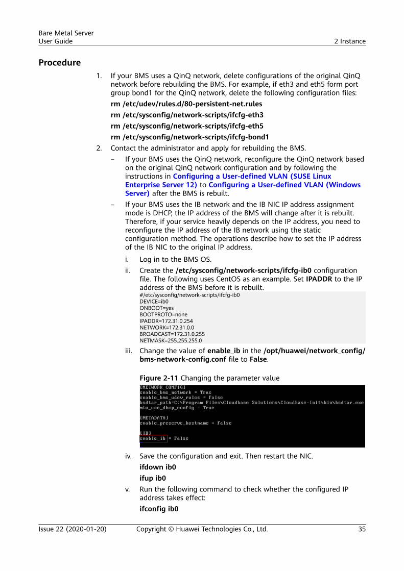
Procedure1. If your BMS uses a QinQ network, delete configurations of the original QinQ
network before rebuilding the BMS. For example, if eth3 and eth5 form portgroup bond1 for the QinQ network, delete the following configuration files:rm /etc/udev/rules.d/80-persistent-net.rulesrm /etc/sysconfig/network-scripts/ifcfg-eth3rm /etc/sysconfig/network-scripts/ifcfg-eth5rm /etc/sysconfig/network-scripts/ifcfg-bond1
2. Contact the administrator and apply for rebuilding the BMS.– If your BMS uses the QinQ network, reconfigure the QinQ network based
on the original QinQ network configuration and by following theinstructions in Configuring a User-defined VLAN (SUSE LinuxEnterprise Server 12) to Configuring a User-defined VLAN (WindowsServer) after the BMS is rebuilt.
– If your BMS uses the IB network and the IB NIC IP address assignmentmode is DHCP, the IP address of the BMS will change after it is rebuilt.Therefore, if your service heavily depends on the IP address, you need toreconfigure the IP address of the IB network using the staticconfiguration method. The operations describe how to set the IP addressof the IB NIC to the original IP address.
i. Log in to the BMS OS.ii. Create the /etc/sysconfig/network-scripts/ifcfg-ib0 configuration
file. The following uses CentOS as an example. Set IPADDR to the IPaddress of the BMS before it is rebuilt.#/etc/sysconfig/network-scripts/ifcfg-ib0DEVICE=ib0ONBOOT=yesBOOTPROTO=noneIPADDR=172.31.0.254NETWORK=172.31.0.0BROADCAST=172.31.0.255NETMASK=255.255.255.0
iii. Change the value of enable_ib in the /opt/huawei/network_config/bms-network-config.conf file to False.
Figure 2-11 Changing the parameter value
iv. Save the configuration and exit. Then restart the NIC.ifdown ib0ifup ib0
v. Run the following command to check whether the configured IPaddress takes effect:ifconfig ib0
Bare Metal ServerUser Guide 2 Instance
Issue 22 (2020-01-20) Copyright © Huawei Technologies Co., Ltd. 35
2.5.7 Backing Up a BMS
Scenarios
To ensure data security, you can back up all EVS system and data disks of a BMS.This backup mode prevents data inconsistency caused by the difference in thebackup creation time. The Cloud Server Backup Service (CSBS) offers the backupservice for BMSs. It works based on the consistent snapshot technology for ElasticVolume Service (EVS) disks. With CSBS, you can use backup data to restore BMSdata, ensuring data security and correctness.
Restrictions and Limitations● BMS backups cannot be used to create images.● BMSs with shared EVS disks cannot be backed up.● When the BMS is restored using backup, the BMS will automatically stop,
which will interrupt tenant services. After the BMS is stopped, it is locked for aspecified time period during which tenants cannot perform operations on theBMS.
Procedure1. Log in to the management console.2. Under Computing, click Bare Metal Server.
The BMS console is displayed.3. Locate the row that contains the target BMS, click More in the Operation
column, and select Create Backup.The Create CSBS Backup page is displayed.
4. Perform the following operations as prompted:– Select a BMS: By default, the BMS to be backed up is selected in the BMS
list. Retain the default.– Configure the backup: Select Auto Backup and select a backup policy.
After the selected BMS is associated with the backup policy, the BMS will beautomatically backed up based on the backup policy.
If the selected BMS has been associated with other policy, it will be disassociatedfrom the original policy automatically and then associated with the new policy.
You can also select back up now. The selected BMS will be backed upimmediately.
For more information, see Cloud Backup and Recovery Getting Started.
2.5.8 Releasing a BMS
Scenarios
You can delete BMSs you no longer need. Once the status of a BMS becomesDeleted, no fees will be incurred for the BMS.
Bare Metal ServerUser Guide 2 Instance
Issue 22 (2020-01-20) Copyright © Huawei Technologies Co., Ltd. 36
After a BMS is deleted, it is still displayed in the BMS list for a short period oftime, after which it will be deleted from the BMS list. Tags and disks of the BMSwill be disassociated from the BMS, and data on the disks will be deleted.
You can manually release a BMS billed in yearly/monthly mode after the validity periodends. If you do not renew the BMS, it will be released automatically. Before the BMSexpires, you can apply for unsubscription to release the BMS in advance.
Procedure1. Log in to the management console.2. Under Computing, click Bare Metal Server.
The BMS console is displayed.3. Locate the row that contains the target BMS, click More in the Operation
column, and select Unsubscribe from the drop-down list.4. On the Unsubscribes page, select a reason and click Unsubscribe.5. Enter the verification code you receive and click OK.
2.6 Using User Data and Metadata
2.6.1 Injecting User Data into BMSs
Application ScenariosUse the user data injection function to inject user data into BMSs to:
● Use scripts to simplify BMS configuration.● Use scripts to initialize the BMS OS configuration.● Upload your scripts to BMSs during BMS creation.● Use scripts to perform other operations.
Restrictions● For Linux:
– The image that is used to create BMSs must have Cloud-Init installed.– The user data to be injected must be less than or equal to 32 KB.– User data uploaded as text can contain only ASCII characters. User data
uploaded as a file can contain any characters, and the file size must beless than or equal to 32 KB.
– The image that is used to create ECSs must be a public image, a privateimage created based on a public image, or a private image with Cloud-Init installed.
– The format of the customized scripts must comply with user data scriptspecifications.
– DHCP must be enabled for the VPC, and port 80 must be enabled for thesecurity group in the outbound direction.
Bare Metal ServerUser Guide 2 Instance
Issue 22 (2020-01-20) Copyright © Huawei Technologies Co., Ltd. 37
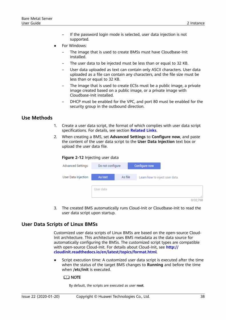
– If the password login mode is selected, user data injection is notsupported.
● For Windows:– The image that is used to create BMSs must have Cloudbase-Init
installed.– The user data to be injected must be less than or equal to 32 KB.– User data uploaded as text can contain only ASCII characters. User data
uploaded as a file can contain any characters, and the file size must beless than or equal to 32 KB.
– The image that is used to create ECSs must be a public image, a privateimage created based on a public image, or a private image withCloudbase-Init installed.
– DHCP must be enabled for the VPC, and port 80 must be enabled for thesecurity group in the outbound direction.
Use Methods1. Create a user data script, the format of which complies with user data script
specifications. For details, see section Related Links.2. When creating a BMS, set Advanced Settings to Configure now, and paste
the content of the user data script to the User Data Injection text box orupload the user data file.
Figure 2-12 Injecting user data
3. The created BMS automatically runs Cloud-Init or Cloudbase-Init to read theuser data script upon startup.
User Data Scripts of Linux BMSs
Customized user data scripts of Linux BMSs are based on the open-source Cloud-Init architecture. This architecture uses BMS metadata as the data source forautomatically configuring the BMSs. The customized script types are compatiblewith open-source Cloud-Init. For details about Cloud-Init, see http://cloudinit.readthedocs.io/en/latest/topics/format.html.
● Script execution time: A customized user data script is executed after the timewhen the status of the target BMS changes to Running and before the timewhen /etc/init is executed.
By default, the scripts are executed as user root.
Bare Metal ServerUser Guide 2 Instance
Issue 22 (2020-01-20) Copyright © Huawei Technologies Co., Ltd. 38
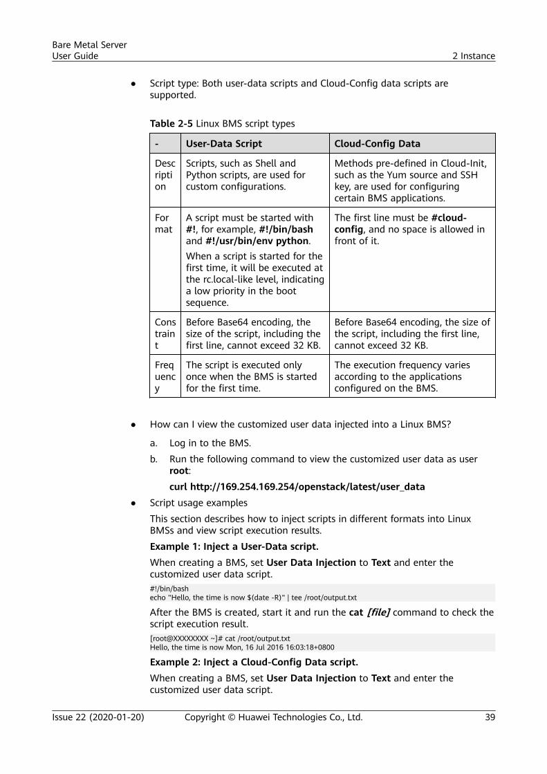
● Script type: Both user-data scripts and Cloud-Config data scripts aresupported.
Table 2-5 Linux BMS script types
- User-Data Script Cloud-Config Data
Description
Scripts, such as Shell andPython scripts, are used forcustom configurations.
Methods pre-defined in Cloud-Init,such as the Yum source and SSHkey, are used for configuringcertain BMS applications.
Format
A script must be started with#!, for example, #!/bin/bashand #!/usr/bin/env python.When a script is started for thefirst time, it will be executed atthe rc.local-like level, indicatinga low priority in the bootsequence.
The first line must be #cloud-config, and no space is allowed infront of it.
Constraint
Before Base64 encoding, thesize of the script, including thefirst line, cannot exceed 32 KB.
Before Base64 encoding, the size ofthe script, including the first line,cannot exceed 32 KB.
Frequency
The script is executed onlyonce when the BMS is startedfor the first time.
The execution frequency variesaccording to the applicationsconfigured on the BMS.
● How can I view the customized user data injected into a Linux BMS?
a. Log in to the BMS.
b. Run the following command to view the customized user data as userroot:
curl http://169.254.169.254/openstack/latest/user_data
● Script usage examples
This section describes how to inject scripts in different formats into LinuxBMSs and view script execution results.
Example 1: Inject a User-Data script.
When creating a BMS, set User Data Injection to Text and enter thecustomized user data script.#!/bin/bashecho "Hello, the time is now $(date -R)" | tee /root/output.txt
After the BMS is created, start it and run the cat [file] command to check thescript execution result.[root@XXXXXXXX ~]# cat /root/output.txtHello, the time is now Mon, 16 Jul 2016 16:03:18+0800
Example 2: Inject a Cloud-Config Data script.
When creating a BMS, set User Data Injection to Text and enter thecustomized user data script.
Bare Metal ServerUser Guide 2 Instance
Issue 22 (2020-01-20) Copyright © Huawei Technologies Co., Ltd. 39
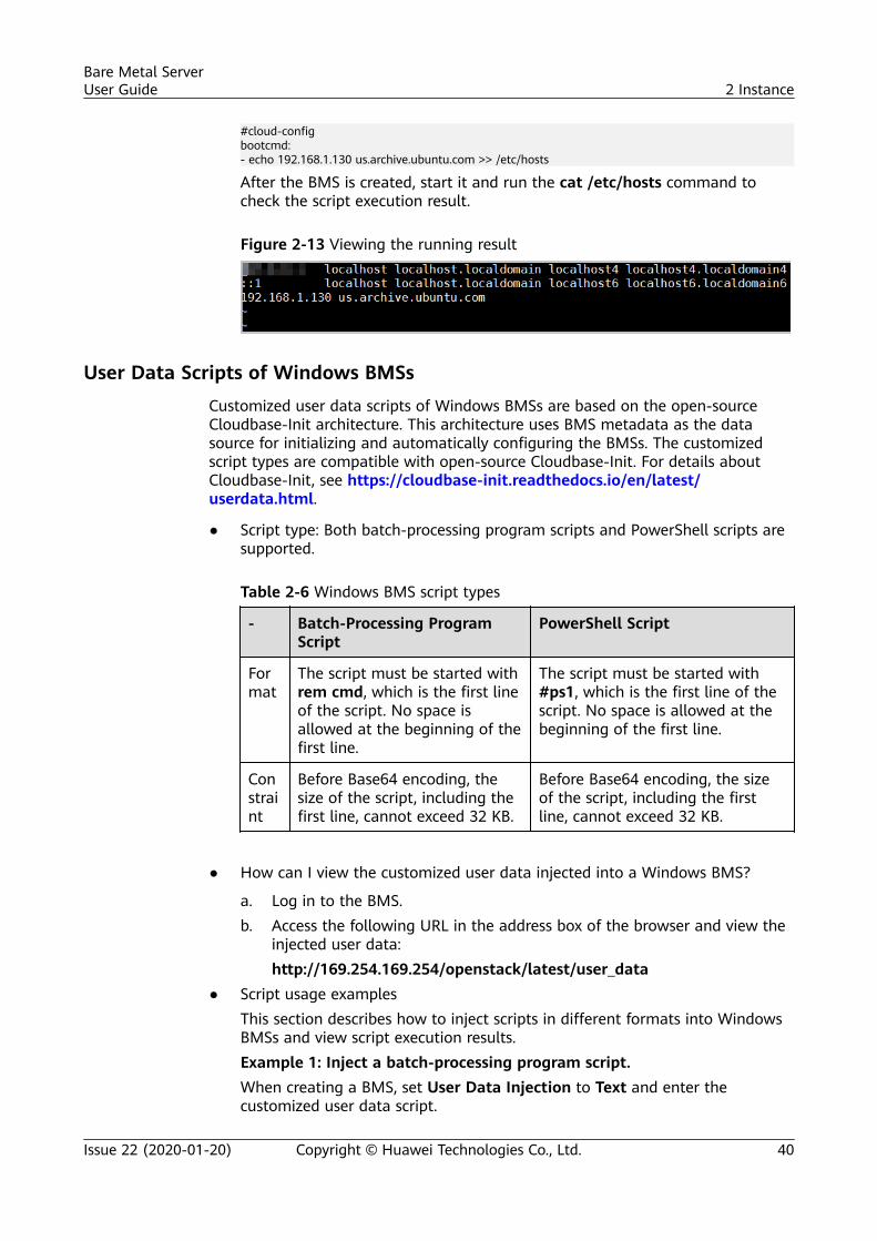
#cloud-configbootcmd:- echo 192.168.1.130 us.archive.ubuntu.com >> /etc/hosts
After the BMS is created, start it and run the cat /etc/hosts command tocheck the script execution result.
Figure 2-13 Viewing the running result
User Data Scripts of Windows BMSs
Customized user data scripts of Windows BMSs are based on the open-sourceCloudbase-Init architecture. This architecture uses BMS metadata as the datasource for initializing and automatically configuring the BMSs. The customizedscript types are compatible with open-source Cloudbase-Init. For details aboutCloudbase-Init, see https://cloudbase-init.readthedocs.io/en/latest/userdata.html.
● Script type: Both batch-processing program scripts and PowerShell scripts aresupported.
Table 2-6 Windows BMS script types
- Batch-Processing ProgramScript
PowerShell Script
Format
The script must be started withrem cmd, which is the first lineof the script. No space isallowed at the beginning of thefirst line.
The script must be started with#ps1, which is the first line of thescript. No space is allowed at thebeginning of the first line.
Constraint
Before Base64 encoding, thesize of the script, including thefirst line, cannot exceed 32 KB.
Before Base64 encoding, the sizeof the script, including the firstline, cannot exceed 32 KB.
● How can I view the customized user data injected into a Windows BMS?
a. Log in to the BMS.b. Access the following URL in the address box of the browser and view the
injected user data:http://169.254.169.254/openstack/latest/user_data
● Script usage examplesThis section describes how to inject scripts in different formats into WindowsBMSs and view script execution results.Example 1: Inject a batch-processing program script.When creating a BMS, set User Data Injection to Text and enter thecustomized user data script.
Bare Metal ServerUser Guide 2 Instance
Issue 22 (2020-01-20) Copyright © Huawei Technologies Co., Ltd. 40
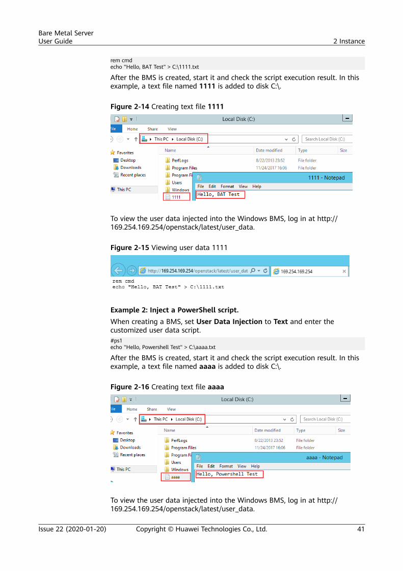
rem cmdecho "Hello, BAT Test" > C:\1111.txt
After the BMS is created, start it and check the script execution result. In thisexample, a text file named 1111 is added to disk C:\.
Figure 2-14 Creating text file 1111
To view the user data injected into the Windows BMS, log in at http://169.254.169.254/openstack/latest/user_data.
Figure 2-15 Viewing user data 1111
Example 2: Inject a PowerShell script.When creating a BMS, set User Data Injection to Text and enter thecustomized user data script.#ps1echo "Hello, Powershell Test" > C:\aaaa.txt
After the BMS is created, start it and check the script execution result. In thisexample, a text file named aaaa is added to disk C:\.
Figure 2-16 Creating text file aaaa
To view the user data injected into the Windows BMS, log in at http://169.254.169.254/openstack/latest/user_data.
Bare Metal ServerUser Guide 2 Instance
Issue 22 (2020-01-20) Copyright © Huawei Technologies Co., Ltd. 41
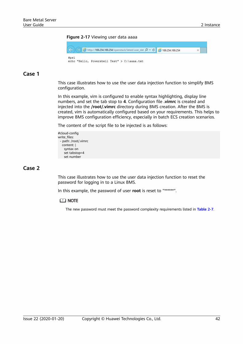
Figure 2-17 Viewing user data aaaa
Case 1This case illustrates how to use the user data injection function to simplify BMSconfiguration.
In this example, vim is configured to enable syntax highlighting, display linenumbers, and set the tab stop to 4. Configuration file .vimrc is created andinjected into the /root/.vimrc directory during BMS creation. After the BMS iscreated, vim is automatically configured based on your requirements. This helps toimprove BMS configuration efficiency, especially in batch ECS creation scenarios.
The content of the script file to be injected is as follows:
#cloud-configwrite_files: - path: /root/.vimrc content: | syntax on set tabstop=4 set number
Case 2This case illustrates how to use the user data injection function to reset thepassword for logging in to a Linux BMS.
In this example, the password of user root is reset to "******".
The new password must meet the password complexity requirements listed in Table 2-7.
Bare Metal ServerUser Guide 2 Instance
Issue 22 (2020-01-20) Copyright © Huawei Technologies Co., Ltd. 42
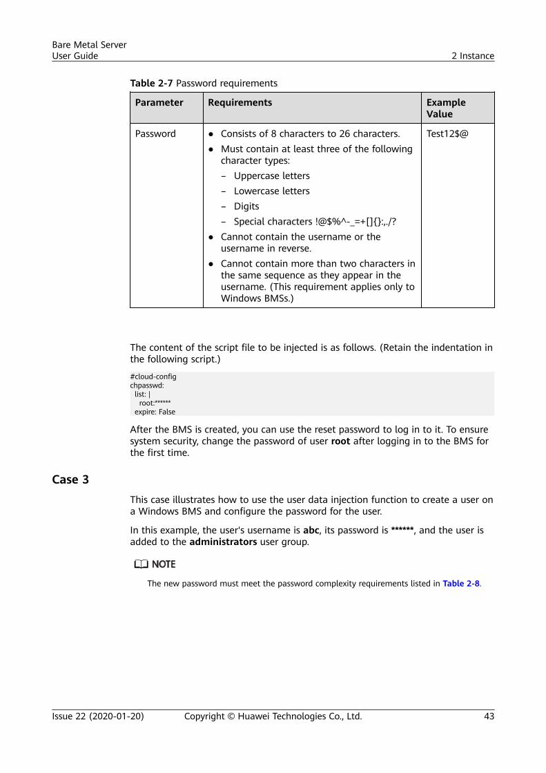
Table 2-7 Password requirements
Parameter Requirements ExampleValue
Password ● Consists of 8 characters to 26 characters.● Must contain at least three of the following
character types:– Uppercase letters– Lowercase letters– Digits– Special characters !@$%^-_=+[]{}:,./?
● Cannot contain the username or theusername in reverse.
● Cannot contain more than two characters inthe same sequence as they appear in theusername. (This requirement applies only toWindows BMSs.)
Test12$@
The content of the script file to be injected is as follows. (Retain the indentation inthe following script.)
#cloud-configchpasswd: list: | root:****** expire: False
After the BMS is created, you can use the reset password to log in to it. To ensuresystem security, change the password of user root after logging in to the BMS forthe first time.
Case 3This case illustrates how to use the user data injection function to create a user ona Windows BMS and configure the password for the user.
In this example, the user's username is abc, its password is ******, and the user isadded to the administrators user group.
The new password must meet the password complexity requirements listed in Table 2-8.
Bare Metal ServerUser Guide 2 Instance
Issue 22 (2020-01-20) Copyright © Huawei Technologies Co., Ltd. 43
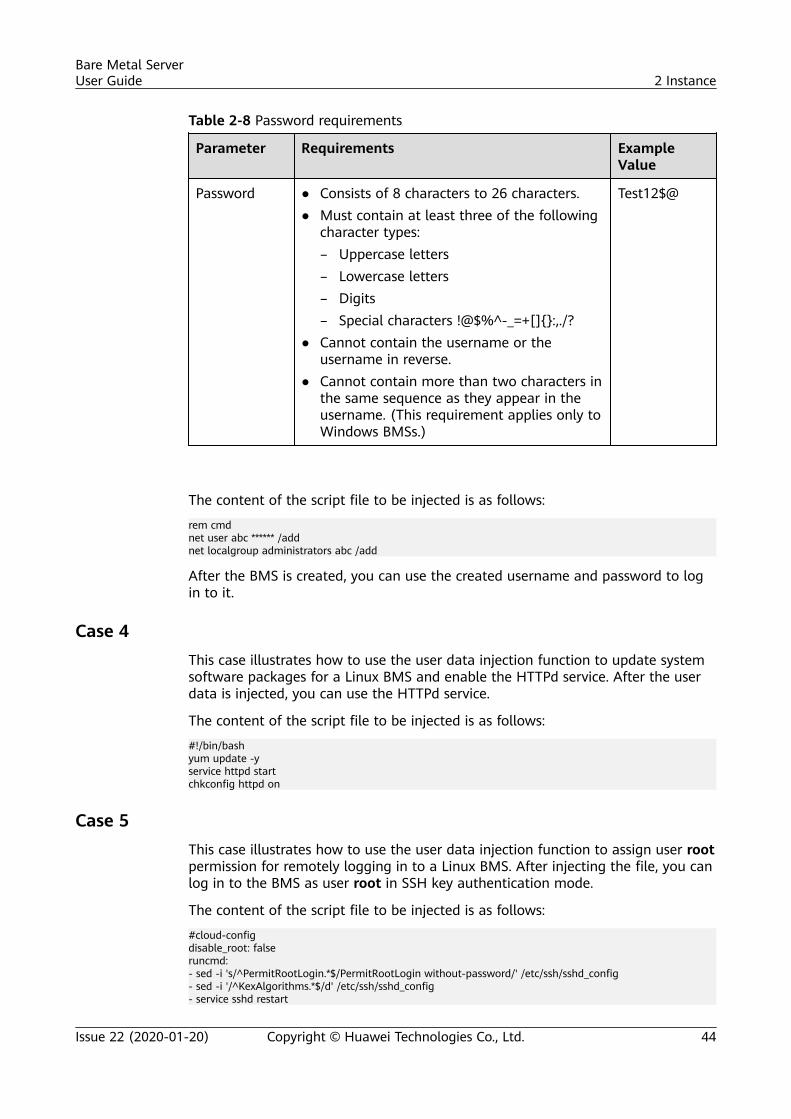
Table 2-8 Password requirements
Parameter Requirements ExampleValue
Password ● Consists of 8 characters to 26 characters.● Must contain at least three of the following
character types:– Uppercase letters– Lowercase letters– Digits– Special characters !@$%^-_=+[]{}:,./?
● Cannot contain the username or theusername in reverse.
● Cannot contain more than two characters inthe same sequence as they appear in theusername. (This requirement applies only toWindows BMSs.)
Test12$@
The content of the script file to be injected is as follows:
rem cmdnet user abc ****** /addnet localgroup administrators abc /add
After the BMS is created, you can use the created username and password to login to it.
Case 4This case illustrates how to use the user data injection function to update systemsoftware packages for a Linux BMS and enable the HTTPd service. After the userdata is injected, you can use the HTTPd service.
The content of the script file to be injected is as follows:
#!/bin/bashyum update -yservice httpd startchkconfig httpd on
Case 5This case illustrates how to use the user data injection function to assign user rootpermission for remotely logging in to a Linux BMS. After injecting the file, you canlog in to the BMS as user root in SSH key authentication mode.
The content of the script file to be injected is as follows:
#cloud-configdisable_root: falseruncmd:- sed -i 's/^PermitRootLogin.*$/PermitRootLogin without-password/' /etc/ssh/sshd_config- sed -i '/^KexAlgorithms.*$/d' /etc/ssh/sshd_config- service sshd restart
Bare Metal ServerUser Guide 2 Instance
Issue 22 (2020-01-20) Copyright © Huawei Technologies Co., Ltd. 44
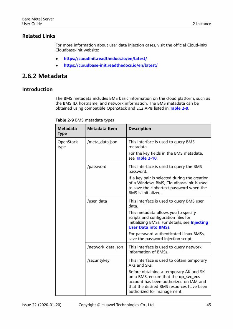
Related Links
For more information about user data injection cases, visit the official Cloud-init/Cloudbase-init website:
● https://cloudinit.readthedocs.io/en/latest/● https://cloudbase-init.readthedocs.io/en/latest/
2.6.2 Metadata
Introduction
The BMS metadata includes BMS basic information on the cloud platform, such asthe BMS ID, hostname, and network information. The BMS metadata can beobtained using compatible OpenStack and EC2 APIs listed in Table 2-9.
Table 2-9 BMS metadata types
MetadataType
Metadata Item Description
OpenStacktype
/meta_data.json This interface is used to query BMSmetadata.For the key fields in the BMS metadata,see Table 2-10.
/password This interface is used to query the BMSpassword.If a key pair is selected during the creationof a Windows BMS, Cloudbase-Init is usedto save the ciphertext password when theBMS is initialized.
/user_data This interface is used to query BMS userdata.This metadata allows you to specifyscripts and configuration files forinitializing BMSs. For details, see InjectingUser Data into BMSs.For password-authenticated Linux BMSs,save the password injection script.
/network_data.json This interface is used to query networkinformation of BMSs.
/securitykey This interface is used to obtain temporaryAKs and SKs.Before obtaining a temporary AK and SKon a BMS, ensure that the op_svc_ecsaccount has been authorized on IAM andthat the desired BMS resources have beenauthorized for management.
Bare Metal ServerUser Guide 2 Instance
Issue 22 (2020-01-20) Copyright © Huawei Technologies Co., Ltd. 45
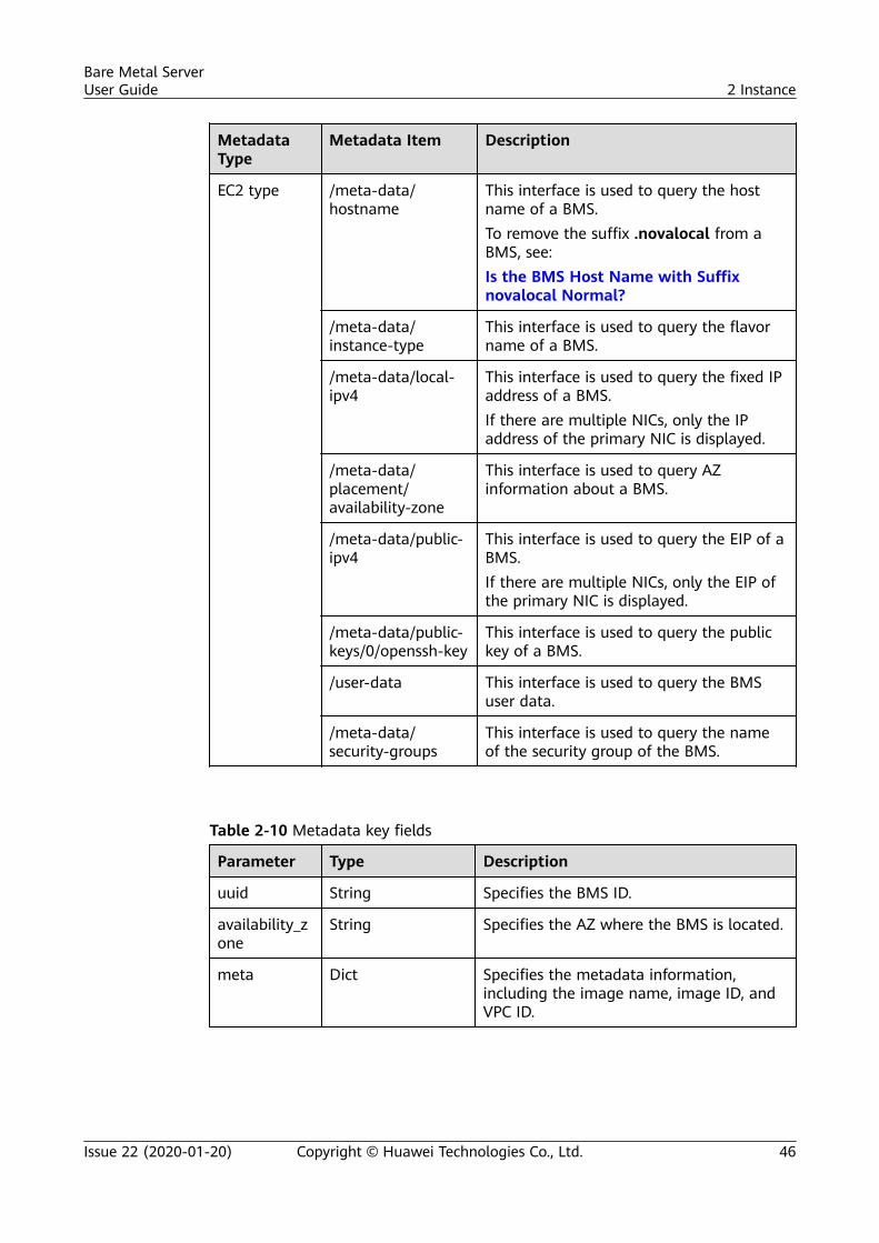
MetadataType
Metadata Item Description
EC2 type /meta-data/hostname
This interface is used to query the hostname of a BMS.To remove the suffix .novalocal from aBMS, see:Is the BMS Host Name with Suffixnovalocal Normal?
/meta-data/instance-type
This interface is used to query the flavorname of a BMS.
/meta-data/local-ipv4
This interface is used to query the fixed IPaddress of a BMS.If there are multiple NICs, only the IPaddress of the primary NIC is displayed.
/meta-data/placement/availability-zone
This interface is used to query AZinformation about a BMS.
/meta-data/public-ipv4
This interface is used to query the EIP of aBMS.If there are multiple NICs, only the EIP ofthe primary NIC is displayed.
/meta-data/public-keys/0/openssh-key
This interface is used to query the publickey of a BMS.
/user-data This interface is used to query the BMSuser data.
/meta-data/security-groups
This interface is used to query the nameof the security group of the BMS.
Table 2-10 Metadata key fields
Parameter Type Description
uuid String Specifies the BMS ID.
availability_zone
String Specifies the AZ where the BMS is located.
meta Dict Specifies the metadata information,including the image name, image ID, andVPC ID.
Bare Metal ServerUser Guide 2 Instance
Issue 22 (2020-01-20) Copyright © Huawei Technologies Co., Ltd. 46
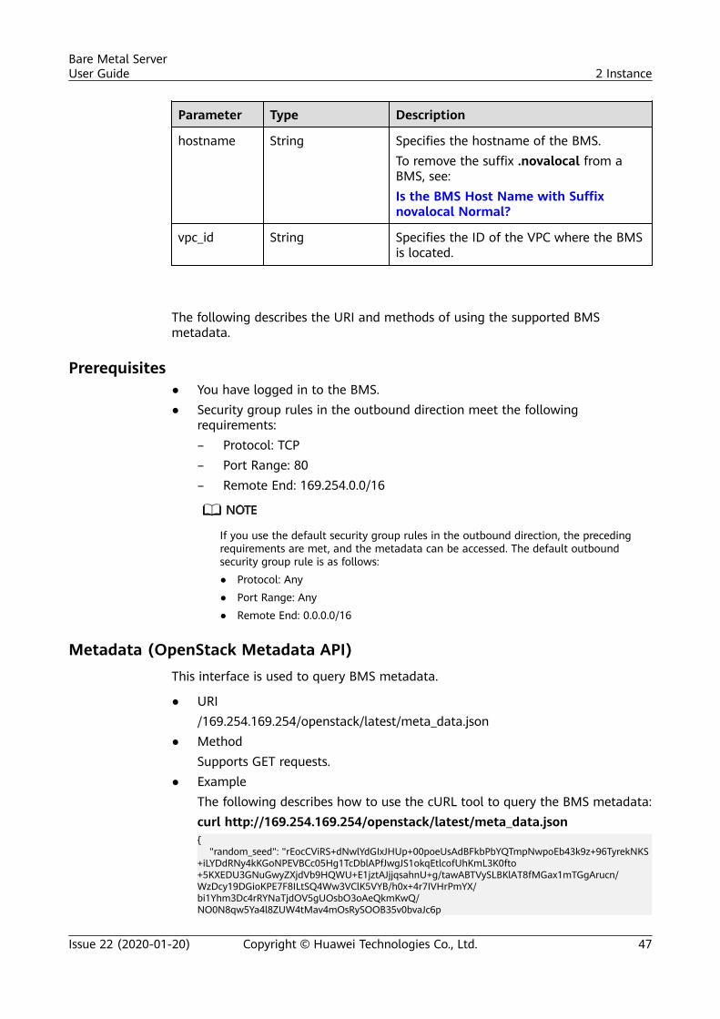
Parameter Type Description
hostname String Specifies the hostname of the BMS.To remove the suffix .novalocal from aBMS, see:Is the BMS Host Name with Suffixnovalocal Normal?
vpc_id String Specifies the ID of the VPC where the BMSis located.
The following describes the URI and methods of using the supported BMSmetadata.
Prerequisites● You have logged in to the BMS.● Security group rules in the outbound direction meet the following
requirements:– Protocol: TCP– Port Range: 80– Remote End: 169.254.0.0/16
If you use the default security group rules in the outbound direction, the precedingrequirements are met, and the metadata can be accessed. The default outboundsecurity group rule is as follows:● Protocol: Any● Port Range: Any● Remote End: 0.0.0.0/16
Metadata (OpenStack Metadata API)This interface is used to query BMS metadata.
● URI/169.254.169.254/openstack/latest/meta_data.json
● MethodSupports GET requests.
● ExampleThe following describes how to use the cURL tool to query the BMS metadata:curl http://169.254.169.254/openstack/latest/meta_data.json{ "random_seed": "rEocCViRS+dNwlYdGIxJHUp+00poeUsAdBFkbPbYQTmpNwpoEb43k9z+96TyrekNKS+iLYDdRNy4kKGoNPEVBCc05Hg1TcDblAPfJwgJS1okqEtlcofUhKmL3K0fto+5KXEDU3GNuGwyZXjdVb9HQWU+E1jztAJjjqsahnU+g/tawABTVySLBKlAT8fMGax1mTGgArucn/WzDcy19DGioKPE7F8ILtSQ4Ww3VClK5VYB/h0x+4r7IVHrPmYX/bi1Yhm3Dc4rRYNaTjdOV5gUOsbO3oAeQkmKwQ/NO0N8qw5Ya4l8ZUW4tMav4mOsRySOOB35v0bvaJc6p
Bare Metal ServerUser Guide 2 Instance
Issue 22 (2020-01-20) Copyright © Huawei Technologies Co., Ltd. 47
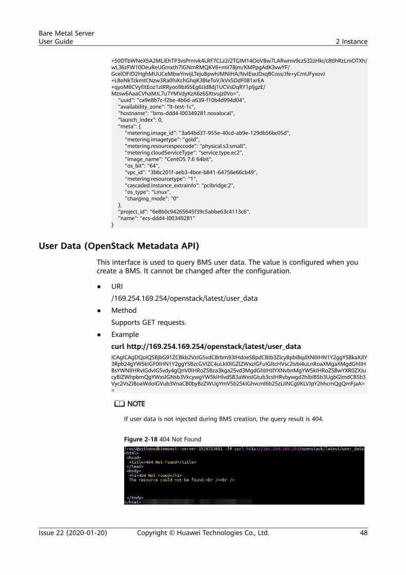
+50DTbWNeX5A2MLiEhTP3vsPrmvk4LRF7CLz2J2TGIM14OoVBw7LARwmv9cz532zHki/c8tlhRzLmOTXh/wL36zFW10DeuReUGmxth7IGNmRMQKV6+miI78jm/KMPpgAdK3vwYF/GcelOFJD2HghMUUCeMbwYnvijLTejuBpwhJMNiHA/NvlEsxJDxqBCoss/Jfe+yCmUFyxovJ+L8oNkTzkmtCNzw3Ra0hiKchGhqK3BIeToV/kVx5DdF081xrEA+qyoM6CVyfJtEoz1zlRRyoo9bJ65Eg6JJd8dj1UCVsDqRY1pIjgzE/Mzsw6AaaCVhaMJL7u7YMVdyKzA6z65Xtvujz0Vo=", "uuid": "ca9e8b7c-f2be-4b6d-a639-f10b4d994d04", "availability_zone": "lt-test-1c", "hostname": "bms-ddd4-l00349281.novalocal", "launch_index": 0, "meta": { "metering.image_id": "3a64bd37-955e-40cd-ab9e-129db56bc05d", "metering.imagetype": "gold", "metering.resourcespeccode": "physical.s3.small", "metering.cloudServiceType": "service.type.ec2", "image_name": "CentOS 7.6 64bit", "os_bit": "64", "vpc_id": "3b6c201f-aeb3-4bce-b841-64756e66cb49", "metering.resourcetype": "1", "cascaded.instance_extrainfo": "pcibridge:2", "os_type": "Linux", "charging_mode": "0" }, "project_id": "6e8b0c94265645f39c5abbe63c4113c6", "name": "ecs-ddd4-l00349281"}
User Data (OpenStack Metadata API)
This interface is used to query BMS user data. The value is configured when youcreate a BMS. It cannot be changed after the configuration.
● URI
/169.254.169.254/openstack/latest/user_data
● Method
Supports GET requests.
● Example
curl http://169.254.169.254/openstack/latest/user_dataICAgICAgDQoiQSBjbG91ZCBkb2VzIG5vdCBrbm93IHdoeSBpdCBtb3ZlcyBpbiBqdXN0IHN1Y2ggYSBkaXJlY3Rpb24gYW5kIGF0IHN1Y2ggYSBzcGVlZC4uLkl0IGZlZWxzIGFuIGltcHVsc2lvbi4uLnRoaXMgaXMgdGhlIHBsYWNlIHRvIGdvIG5vdy4gQnV0IHRoZSBza3kga25vd3MgdGhlIHJlYXNvbnMgYW5kIHRoZSBwYXR0ZXJucyBiZWhpbmQgYWxsIGNsb3VkcywgYW5kIHlvdSB3aWxsIGtub3csIHRvbywgd2hlbiB5b3UgbGlmdCB5b3Vyc2VsZiBoaWdoIGVub3VnaCB0byBzZWUgYmV5b25kIGhvcml6b25zLiINCg0KLVJpY2hhcmQgQmFjaA==
If user data is not injected during BMS creation, the query result is 404.
Figure 2-18 404 Not Found
Bare Metal ServerUser Guide 2 Instance
Issue 22 (2020-01-20) Copyright © Huawei Technologies Co., Ltd. 48
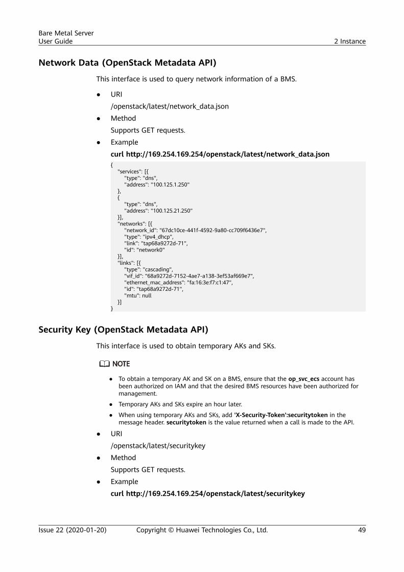
Network Data (OpenStack Metadata API)
This interface is used to query network information of a BMS.
● URI
/openstack/latest/network_data.json
● Method
Supports GET requests.
● Example
curl http://169.254.169.254/openstack/latest/network_data.json{ "services": [{ "type": "dns", "address": "100.125.1.250" }, { "type": "dns", "address": "100.125.21.250" }], "networks": [{ "network_id": "67dc10ce-441f-4592-9a80-cc709f6436e7", "type": "ipv4_dhcp", "link": "tap68a9272d-71", "id": "network0" }], "links": [{ "type": "cascading", "vif_id": "68a9272d-7152-4ae7-a138-3ef53af669e7", "ethernet_mac_address": "fa:16:3e:f7:c1:47", "id": "tap68a9272d-71", "mtu": null }]}
Security Key (OpenStack Metadata API)
This interface is used to obtain temporary AKs and SKs.
● To obtain a temporary AK and SK on a BMS, ensure that the op_svc_ecs account hasbeen authorized on IAM and that the desired BMS resources have been authorized formanagement.
● Temporary AKs and SKs expire an hour later.
● When using temporary AKs and SKs, add 'X-Security-Token':securitytoken in themessage header. securitytoken is the value returned when a call is made to the API.
● URI
/openstack/latest/securitykey
● Method
Supports GET requests.
● Example
curl http://169.254.169.254/openstack/latest/securitykey
Bare Metal ServerUser Guide 2 Instance
Issue 22 (2020-01-20) Copyright © Huawei Technologies Co., Ltd. 49
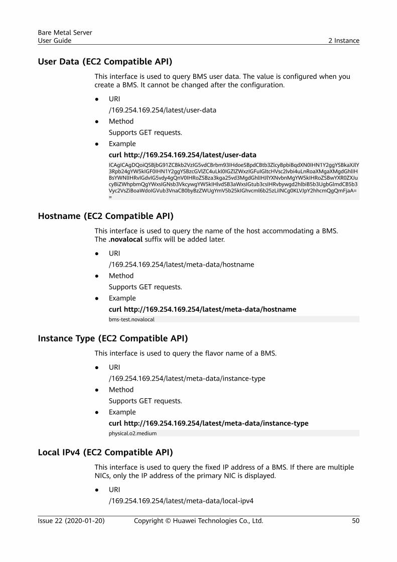
User Data (EC2 Compatible API)This interface is used to query BMS user data. The value is configured when youcreate a BMS. It cannot be changed after the configuration.
● URI/169.254.169.254/latest/user-data
● MethodSupports GET requests.
● Examplecurl http://169.254.169.254/latest/user-dataICAgICAgDQoiQSBjbG91ZCBkb2VzIG5vdCBrbm93IHdoeSBpdCBtb3ZlcyBpbiBqdXN0IHN1Y2ggYSBkaXJlY3Rpb24gYW5kIGF0IHN1Y2ggYSBzcGVlZC4uLkl0IGZlZWxzIGFuIGltcHVsc2lvbi4uLnRoaXMgaXMgdGhlIHBsYWNlIHRvIGdvIG5vdy4gQnV0IHRoZSBza3kga25vd3MgdGhlIHJlYXNvbnMgYW5kIHRoZSBwYXR0ZXJucyBiZWhpbmQgYWxsIGNsb3VkcywgYW5kIHlvdSB3aWxsIGtub3csIHRvbywgd2hlbiB5b3UgbGlmdCB5b3Vyc2VsZiBoaWdoIGVub3VnaCB0byBzZWUgYmV5b25kIGhvcml6b25zLiINCg0KLVJpY2hhcmQgQmFjaA==
Hostname (EC2 Compatible API)This interface is used to query the name of the host accommodating a BMS.The .novalocal suffix will be added later.
● URI/169.254.169.254/latest/meta-data/hostname
● MethodSupports GET requests.
● Examplecurl http://169.254.169.254/latest/meta-data/hostnamebms-test.novalocal
Instance Type (EC2 Compatible API)This interface is used to query the flavor name of a BMS.
● URI/169.254.169.254/latest/meta-data/instance-type
● MethodSupports GET requests.
● Examplecurl http://169.254.169.254/latest/meta-data/instance-typephysical.o2.medium
Local IPv4 (EC2 Compatible API)This interface is used to query the fixed IP address of a BMS. If there are multipleNICs, only the IP address of the primary NIC is displayed.
● URI/169.254.169.254/latest/meta-data/local-ipv4
Bare Metal ServerUser Guide 2 Instance
Issue 22 (2020-01-20) Copyright © Huawei Technologies Co., Ltd. 50
● MethodSupports GET requests.
● Examplecurl http://169.254.169.254/latest/meta-data/local-ipv4192.1.1.2
Availability Zone (EC2 Compatible API)
This interface is used to query AZ information about a BMS.
● URI/169.254.169.254/latest/meta-data/placement/availability-zone
● MethodSupports GET requests.
● Examplecurl http://169.254.169.254/latest/meta-data/placement/availability-zoneaz1.dc1
Public IPv4 (EC2 Compatible API)
This interface is used to query the EIP of a BMS. If there are multiple NICs, onlythe EIP of the primary NIC is displayed.
● URI/169.254.169.254/latest/meta-data/public-ipv4
● MethodSupports GET requests.
● Examplecurl http://169.254.169.254/latest/meta-data/public-ipv446.1.1.2
Public Keys (EC2 Compatible API)
This interface is used to query the public key of a BMS.
● URI/169.254.169.254/latest/meta-data/public-keys/0/openssh-key
● MethodSupports GET requests.
● Examplecurl http://169.254.169.254/latest/meta-data/public-keys/0/openssh-keyssh-rsa AAAAB3NzaC1yc2EAAAADAQABAAABAQDI5Fw5k8Fgzajn1zJwLoV3+wMP+6CyvsSiIc/hioggSnYu/AD0Yqm8vVO0kWlun1rFbdO+QUZKyVr/OPUjQSw4SRh4qsTKf/+eFoWTjplFvd1WCBZzS/WRenxIwR00KkczHSJro763+wYcwKieb4eKRxaQoQvoFgVjLBULXAjH4eKoKTVNtMXAvPP9aMy2SLgsJNtMb9ArfziAiblQynq7UIfLnN3VclzPeiWrqtzjyOp6CPUXnL0lVPTvbLe8sUteBsJZwlL6K4i+Y0lf3ryqnmQgC21yW4Dzu+kwk8FVT2MgWkCwiZd8gQ/+uJzrJFyMfUOBIklOBfuUENIJUhAB Generated-by-Nova
Bare Metal ServerUser Guide 2 Instance
Issue 22 (2020-01-20) Copyright © Huawei Technologies Co., Ltd. 51
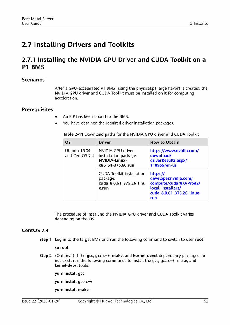
2.7 Installing Drivers and Toolkits
2.7.1 Installing the NVIDIA GPU Driver and CUDA Toolkit on aP1 BMS
ScenariosAfter a GPU-accelerated P1 BMS (using the physical.p1.large flavor) is created, theNVIDIA GPU driver and CUDA Toolkit must be installed on it for computingacceleration.
Prerequisites● An EIP has been bound to the BMS.● You have obtained the required driver installation packages.
Table 2-11 Download paths for the NVIDIA GPU driver and CUDA Toolkit
OS Driver How to Obtain
Ubuntu 16.04and CentOS 7.4
NVIDIA GPU driverinstallation package:NVIDIA-Linux-x86_64-375.66.run
https://www.nvidia.com/download/driverResults.aspx/118955/en-us
CUDA Toolkit installationpackage:cuda_8.0.61_375.26_linux.run
https://developer.nvidia.com/compute/cuda/8.0/Prod2/local_installers/cuda_8.0.61_375.26_linux-run
The procedure of installing the NVIDIA GPU driver and CUDA Toolkit variesdepending on the OS.
CentOS 7.4
Step 1 Log in to the target BMS and run the following command to switch to user root:
su root
Step 2 (Optional) If the gcc, gcc-c++, make, and kernel-devel dependency packages donot exist, run the following commands to install the gcc, gcc-c++, make, andkernel-devel tools:
yum install gcc
yum install gcc-c++
yum install make
Bare Metal ServerUser Guide 2 Instance
Issue 22 (2020-01-20) Copyright © Huawei Technologies Co., Ltd. 52
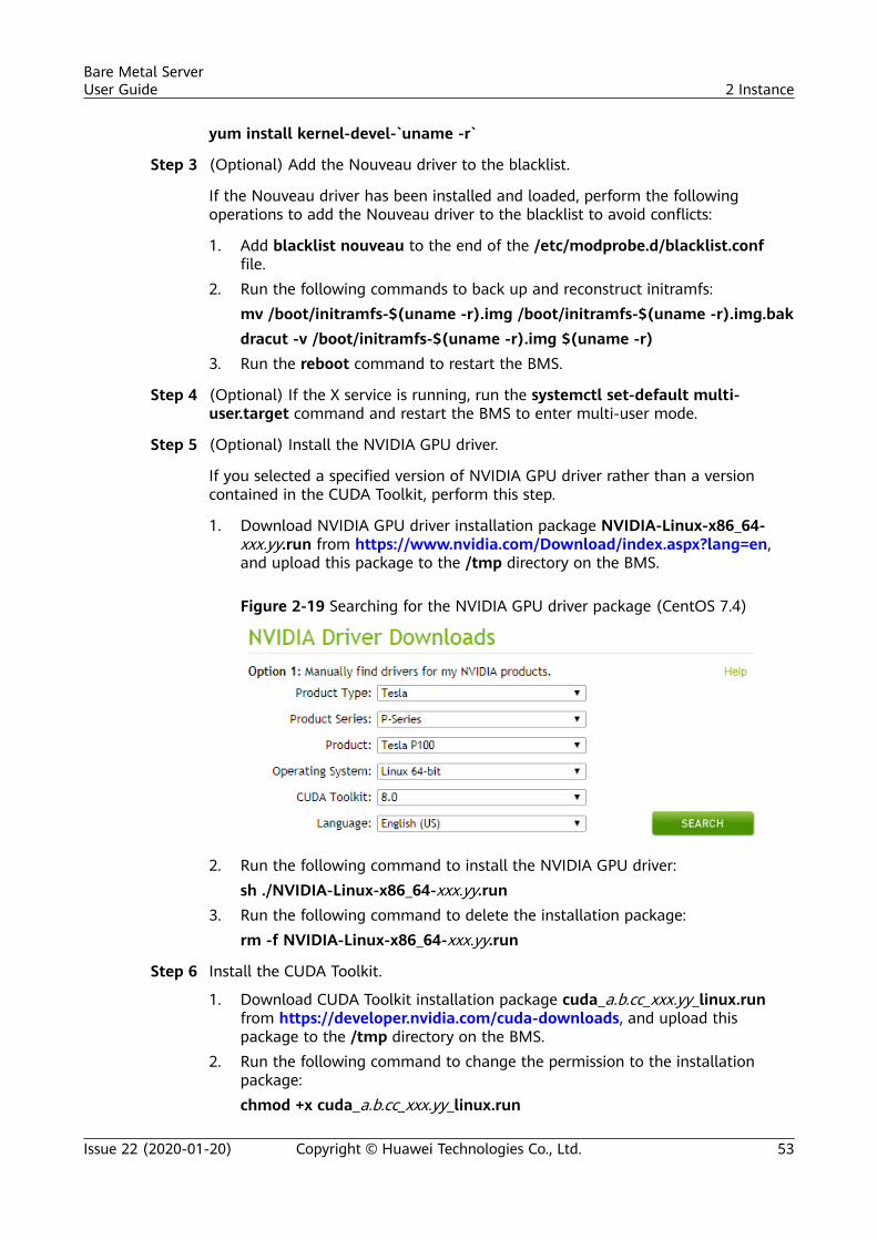
yum install kernel-devel-`uname -r`
Step 3 (Optional) Add the Nouveau driver to the blacklist.
If the Nouveau driver has been installed and loaded, perform the followingoperations to add the Nouveau driver to the blacklist to avoid conflicts:
1. Add blacklist nouveau to the end of the /etc/modprobe.d/blacklist.conffile.
2. Run the following commands to back up and reconstruct initramfs:mv /boot/initramfs-$(uname -r).img /boot/initramfs-$(uname -r).img.bakdracut -v /boot/initramfs-$(uname -r).img $(uname -r)
3. Run the reboot command to restart the BMS.
Step 4 (Optional) If the X service is running, run the systemctl set-default multi-user.target command and restart the BMS to enter multi-user mode.
Step 5 (Optional) Install the NVIDIA GPU driver.
If you selected a specified version of NVIDIA GPU driver rather than a versioncontained in the CUDA Toolkit, perform this step.
1. Download NVIDIA GPU driver installation package NVIDIA-Linux-x86_64-xxx.yy.run from https://www.nvidia.com/Download/index.aspx?lang=en,and upload this package to the /tmp directory on the BMS.
Figure 2-19 Searching for the NVIDIA GPU driver package (CentOS 7.4)
2. Run the following command to install the NVIDIA GPU driver:sh ./NVIDIA-Linux-x86_64-xxx.yy.run
3. Run the following command to delete the installation package:rm -f NVIDIA-Linux-x86_64-xxx.yy.run
Step 6 Install the CUDA Toolkit.
1. Download CUDA Toolkit installation package cuda_a.b.cc_xxx.yy_linux.runfrom https://developer.nvidia.com/cuda-downloads, and upload thispackage to the /tmp directory on the BMS.
2. Run the following command to change the permission to the installationpackage:chmod +x cuda_a.b.cc_xxx.yy_linux.run
Bare Metal ServerUser Guide 2 Instance
Issue 22 (2020-01-20) Copyright © Huawei Technologies Co., Ltd. 53
3. Run the following command to install the CUDA Toolkit:./cuda_a.b.cc_xxx.yy_linux.run -toolkit -samples -silent -override --tmpdir=/tmp/
4. Run the following command to delete the installation package:rm -f cuda_a.b.cc_xxx.yy_linux.run
5. Run the following commands to check whether the installation is successful:cd /usr/local/cuda/samples/1_Utilities/deviceQueryDrv/make./deviceQueryDrvIf the command output contains "Result = PASS", the CUDA Toolkit and theNVIDIA GPU driver have been installed successfully.
----End
Ubuntu 16.04
Step 1 Log in to the target BMS and run the following command to switch to user root:
sudo root
Step 2 (Optional) If the gcc, g++, and make dependency packages do not exist, run thefollowing commands to install the gcc, g++, and make tools:
apt-get install gcc
apt-get install g++
apt-get install make
Step 3 (Optional) Add the Nouveau driver to the blacklist.
If the Nouveau driver has been installed and loaded, perform the followingoperations to add the Nouveau driver to the blacklist to avoid conflicts:
1. Add the following information to the end of the /etc/modprobe.d/blacklist.conf file:blacklist nouveauoptions nouveau modeset=0
2. Run the following commands to back up and reconstruct initramfs:mv /boot/initramfs-$(uname -r).img /boot/initramfs-$(uname -r).img.baksudo update-initramfs -u
3. Run the sudo reboot command to restart the BMS.
Step 4 (Optional) If the X service is running, run the systemctl set-default multi-user.target command and restart the BMS to enter multi-user mode.
Step 5 (Optional) Install the NVIDIA GPU driver.
If you selected a specified version of NVIDIA GPU driver rather than a versioncontained in the CUDA Toolkit, perform this step.
1. Download NVIDIA GPU driver installation package NVIDIA-Linux-x86_64-xxx.yy.run from https://www.nvidia.com/Download/index.aspx?lang=en,and upload this package to the /tmp directory on the BMS.
Bare Metal ServerUser Guide 2 Instance
Issue 22 (2020-01-20) Copyright © Huawei Technologies Co., Ltd. 54
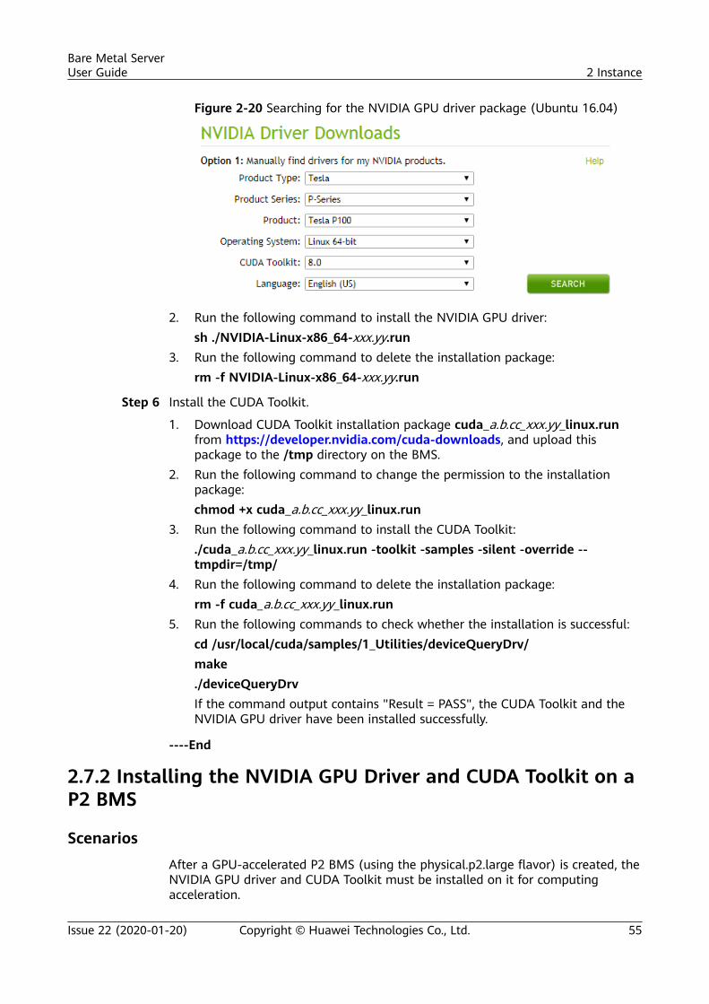
Figure 2-20 Searching for the NVIDIA GPU driver package (Ubuntu 16.04)
2. Run the following command to install the NVIDIA GPU driver:sh ./NVIDIA-Linux-x86_64-xxx.yy.run
3. Run the following command to delete the installation package:rm -f NVIDIA-Linux-x86_64-xxx.yy.run
Step 6 Install the CUDA Toolkit.
1. Download CUDA Toolkit installation package cuda_a.b.cc_xxx.yy_linux.runfrom https://developer.nvidia.com/cuda-downloads, and upload thispackage to the /tmp directory on the BMS.
2. Run the following command to change the permission to the installationpackage:chmod +x cuda_a.b.cc_xxx.yy_linux.run
3. Run the following command to install the CUDA Toolkit:./cuda_a.b.cc_xxx.yy_linux.run -toolkit -samples -silent -override --tmpdir=/tmp/
4. Run the following command to delete the installation package:rm -f cuda_a.b.cc_xxx.yy_linux.run
5. Run the following commands to check whether the installation is successful:cd /usr/local/cuda/samples/1_Utilities/deviceQueryDrv/make./deviceQueryDrvIf the command output contains "Result = PASS", the CUDA Toolkit and theNVIDIA GPU driver have been installed successfully.
----End
2.7.2 Installing the NVIDIA GPU Driver and CUDA Toolkit on aP2 BMS
ScenariosAfter a GPU-accelerated P2 BMS (using the physical.p2.large flavor) is created, theNVIDIA GPU driver and CUDA Toolkit must be installed on it for computingacceleration.
Bare Metal ServerUser Guide 2 Instance
Issue 22 (2020-01-20) Copyright © Huawei Technologies Co., Ltd. 55
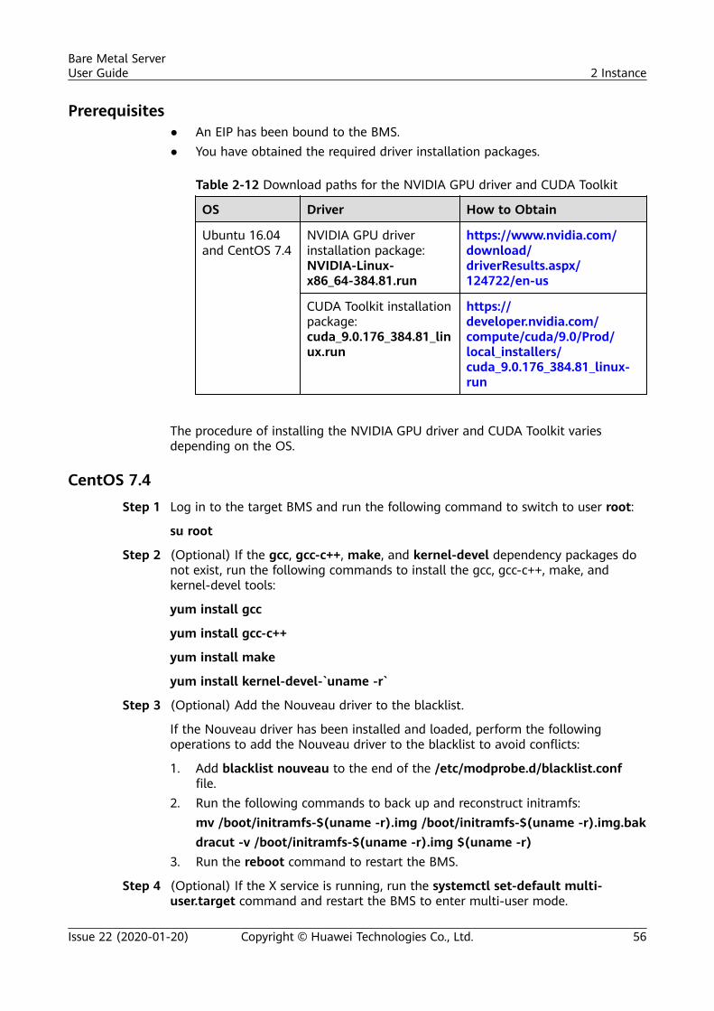
Prerequisites● An EIP has been bound to the BMS.● You have obtained the required driver installation packages.
Table 2-12 Download paths for the NVIDIA GPU driver and CUDA Toolkit
OS Driver How to Obtain
Ubuntu 16.04and CentOS 7.4
NVIDIA GPU driverinstallation package:NVIDIA-Linux-x86_64-384.81.run
https://www.nvidia.com/download/driverResults.aspx/124722/en-us
CUDA Toolkit installationpackage:cuda_9.0.176_384.81_linux.run
https://developer.nvidia.com/compute/cuda/9.0/Prod/local_installers/cuda_9.0.176_384.81_linux-run
The procedure of installing the NVIDIA GPU driver and CUDA Toolkit variesdepending on the OS.
CentOS 7.4Step 1 Log in to the target BMS and run the following command to switch to user root:
su root
Step 2 (Optional) If the gcc, gcc-c++, make, and kernel-devel dependency packages donot exist, run the following commands to install the gcc, gcc-c++, make, andkernel-devel tools:
yum install gcc
yum install gcc-c++
yum install make
yum install kernel-devel-`uname -r`
Step 3 (Optional) Add the Nouveau driver to the blacklist.
If the Nouveau driver has been installed and loaded, perform the followingoperations to add the Nouveau driver to the blacklist to avoid conflicts:
1. Add blacklist nouveau to the end of the /etc/modprobe.d/blacklist.conffile.
2. Run the following commands to back up and reconstruct initramfs:mv /boot/initramfs-$(uname -r).img /boot/initramfs-$(uname -r).img.bakdracut -v /boot/initramfs-$(uname -r).img $(uname -r)
3. Run the reboot command to restart the BMS.
Step 4 (Optional) If the X service is running, run the systemctl set-default multi-user.target command and restart the BMS to enter multi-user mode.
Bare Metal ServerUser Guide 2 Instance
Issue 22 (2020-01-20) Copyright © Huawei Technologies Co., Ltd. 56
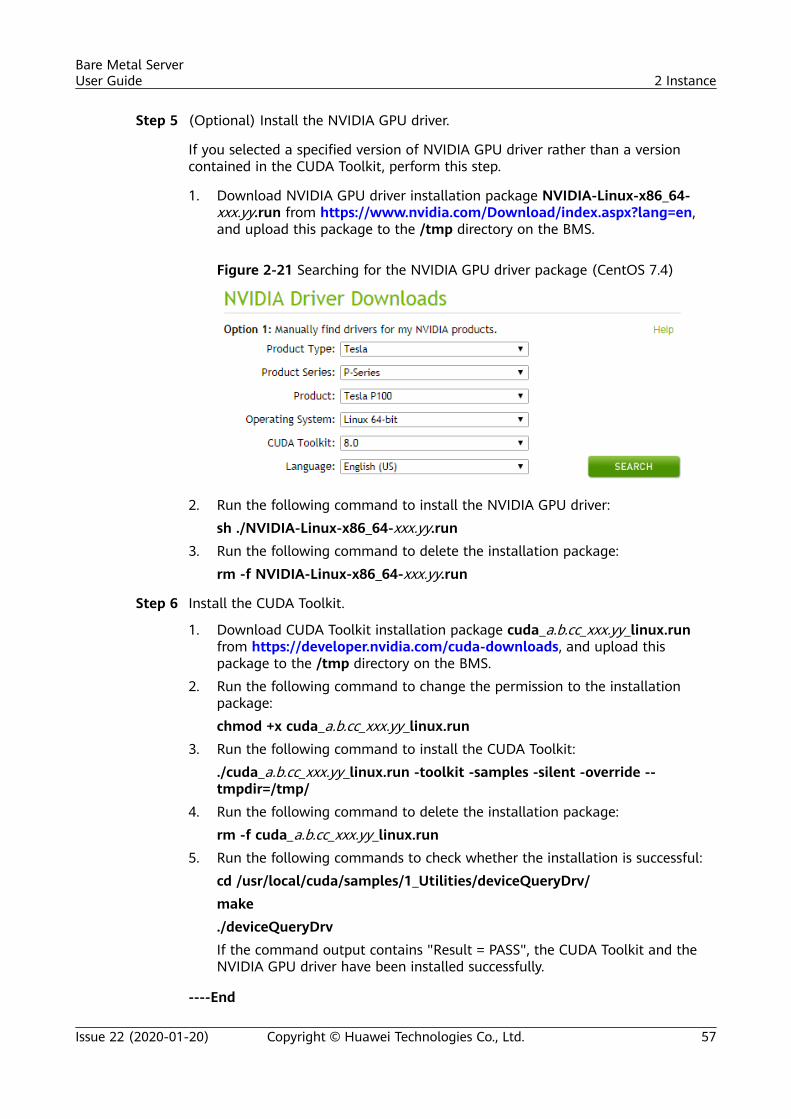
Step 5 (Optional) Install the NVIDIA GPU driver.
If you selected a specified version of NVIDIA GPU driver rather than a versioncontained in the CUDA Toolkit, perform this step.
1. Download NVIDIA GPU driver installation package NVIDIA-Linux-x86_64-xxx.yy.run from https://www.nvidia.com/Download/index.aspx?lang=en,and upload this package to the /tmp directory on the BMS.
Figure 2-21 Searching for the NVIDIA GPU driver package (CentOS 7.4)
2. Run the following command to install the NVIDIA GPU driver:sh ./NVIDIA-Linux-x86_64-xxx.yy.run
3. Run the following command to delete the installation package:rm -f NVIDIA-Linux-x86_64-xxx.yy.run
Step 6 Install the CUDA Toolkit.
1. Download CUDA Toolkit installation package cuda_a.b.cc_xxx.yy_linux.runfrom https://developer.nvidia.com/cuda-downloads, and upload thispackage to the /tmp directory on the BMS.
2. Run the following command to change the permission to the installationpackage:chmod +x cuda_a.b.cc_xxx.yy_linux.run
3. Run the following command to install the CUDA Toolkit:./cuda_a.b.cc_xxx.yy_linux.run -toolkit -samples -silent -override --tmpdir=/tmp/
4. Run the following command to delete the installation package:rm -f cuda_a.b.cc_xxx.yy_linux.run
5. Run the following commands to check whether the installation is successful:cd /usr/local/cuda/samples/1_Utilities/deviceQueryDrv/make./deviceQueryDrvIf the command output contains "Result = PASS", the CUDA Toolkit and theNVIDIA GPU driver have been installed successfully.
----End
Bare Metal ServerUser Guide 2 Instance
Issue 22 (2020-01-20) Copyright © Huawei Technologies Co., Ltd. 57
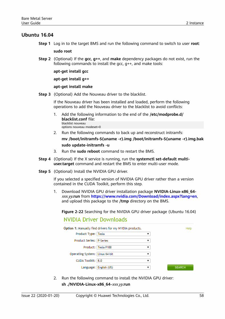
Ubuntu 16.04
Step 1 Log in to the target BMS and run the following command to switch to user root:
sudo root
Step 2 (Optional) If the gcc, g++, and make dependency packages do not exist, run thefollowing commands to install the gcc, g++, and make tools:
apt-get install gcc
apt-get install g++
apt-get install make
Step 3 (Optional) Add the Nouveau driver to the blacklist.
If the Nouveau driver has been installed and loaded, perform the followingoperations to add the Nouveau driver to the blacklist to avoid conflicts:
1. Add the following information to the end of the /etc/modprobe.d/blacklist.conf file:blacklist nouveauoptions nouveau modeset=0
2. Run the following commands to back up and reconstruct initramfs:mv /boot/initramfs-$(uname -r).img /boot/initramfs-$(uname -r).img.baksudo update-initramfs -u
3. Run the sudo reboot command to restart the BMS.
Step 4 (Optional) If the X service is running, run the systemctl set-default multi-user.target command and restart the BMS to enter multi-user mode.
Step 5 (Optional) Install the NVIDIA GPU driver.
If you selected a specified version of NVIDIA GPU driver rather than a versioncontained in the CUDA Toolkit, perform this step.
1. Download NVIDIA GPU driver installation package NVIDIA-Linux-x86_64-xxx.yy.run from https://www.nvidia.com/Download/index.aspx?lang=en,and upload this package to the /tmp directory on the BMS.
Figure 2-22 Searching for the NVIDIA GPU driver package (Ubuntu 16.04)
2. Run the following command to install the NVIDIA GPU driver:sh ./NVIDIA-Linux-x86_64-xxx.yy.run
Bare Metal ServerUser Guide 2 Instance
Issue 22 (2020-01-20) Copyright © Huawei Technologies Co., Ltd. 58
3. Run the following command to delete the installation package:rm -f NVIDIA-Linux-x86_64-xxx.yy.run
Step 6 Install the CUDA Toolkit.
1. Download CUDA Toolkit installation package cuda_a.b.cc_xxx.yy_linux.runfrom https://developer.nvidia.com/cuda-downloads, and upload thispackage to the /tmp directory on the BMS.
2. Run the following command to change the permission to the installationpackage:chmod +x cuda_a.b.cc_xxx.yy_linux.run
3. Run the following command to install the CUDA Toolkit:./cuda_a.b.cc_xxx.yy_linux.run -toolkit -samples -silent -override --tmpdir=/tmp/
4. Run the following command to delete the installation package:rm -f cuda_a.b.cc_xxx.yy_linux.run
5. Run the following commands to check whether the installation is successful:cd /usr/local/cuda/samples/1_Utilities/deviceQueryDrv/make./deviceQueryDrvIf the command output contains "Result = PASS", the CUDA Toolkit and theNVIDIA GPU driver have been installed successfully.
----End
Bare Metal ServerUser Guide 2 Instance
Issue 22 (2020-01-20) Copyright © Huawei Technologies Co., Ltd. 59
3 Image
3.1 Private Image OverviewA private image is an image available only to the user who created it. It containsan OS, preinstalled public applications, and a user's private applications. You cancreate a private image in the following ways:
● Creating a Private Image from a BMS
Currently, only a BMS that supports quick provisioning (the OS is installed on an EVSdisk) can be used to create a private image.
● Creating a Private Image from an External Image FileYou can upload external image files to the cloud platform and register themas your private images. Supported external image formats include VMDK,VHD, QCOW2, RAW, VHDX, QED, VDI, QCOW, ZVHD2, and ZVHD.
Images of other formats must be converted using the image conversion tool beforethey can be used on BMSs.
After a private image is created successfully, the image status becomes Normal.You can use the image to create BMSs or share the image with other tenants. Youcan also replicate the image to your other regions. The following figure showshow to use private images.
Bare Metal ServerUser Guide 3 Image
Issue 22 (2020-01-20) Copyright © Huawei Technologies Co., Ltd. 60
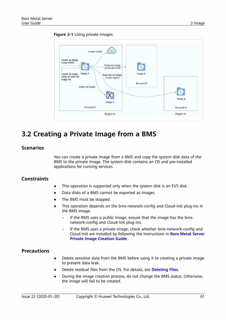
Figure 3-1 Using private images
3.2 Creating a Private Image from a BMS
Scenarios
You can create a private image from a BMS and copy the system disk data of theBMS to the private image. The system disk contains an OS and pre-installedapplications for running services.
Constraints● This operation is supported only when the system disk is an EVS disk.
● Data disks of a BMS cannot be exported as images.
● The BMS must be stopped.
● This operation depends on the bms-network-config and Cloud-Init plug-ins inthe BMS image.
– If the BMS uses a public image, ensure that the image has the bms-network-config and Cloud-Init plug-ins.
– If the BMS uses a private image, check whether bms-network-config andCloud-Init are installed by following the instructions in Bare Metal ServerPrivate Image Creation Guide.
Precautions● Delete sensitive data from the BMS before using it to creating a private image
to prevent data leak.
● Delete residual files from the OS. For details, see Deleting Files.
● During the image creation process, do not change the BMS status. Otherwise,the image will fail to be created.
Bare Metal ServerUser Guide 3 Image
Issue 22 (2020-01-20) Copyright © Huawei Technologies Co., Ltd. 61
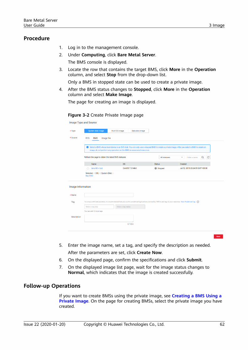
Procedure1. Log in to the management console.
2. Under Computing, click Bare Metal Server.
The BMS console is displayed.
3. Locate the row that contains the target BMS, click More in the Operationcolumn, and select Stop from the drop-down list.
Only a BMS in stopped state can be used to create a private image.
4. After the BMS status changes to Stopped, click More in the Operationcolumn and select Make Image.
The page for creating an image is displayed.
Figure 3-2 Create Private Image page
5. Enter the image name, set a tag, and specify the description as needed.
After the parameters are set, click Create Now.
6. On the displayed page, confirm the specifications and click Submit.
7. On the displayed image list page, wait for the image status changes toNormal, which indicates that the image is created successfully.
Follow-up Operations
If you want to create BMSs using the private image, see Creating a BMS Using aPrivate Image. On the page for creating BMSs, select the private image you havecreated.
Bare Metal ServerUser Guide 3 Image
Issue 22 (2020-01-20) Copyright © Huawei Technologies Co., Ltd. 62
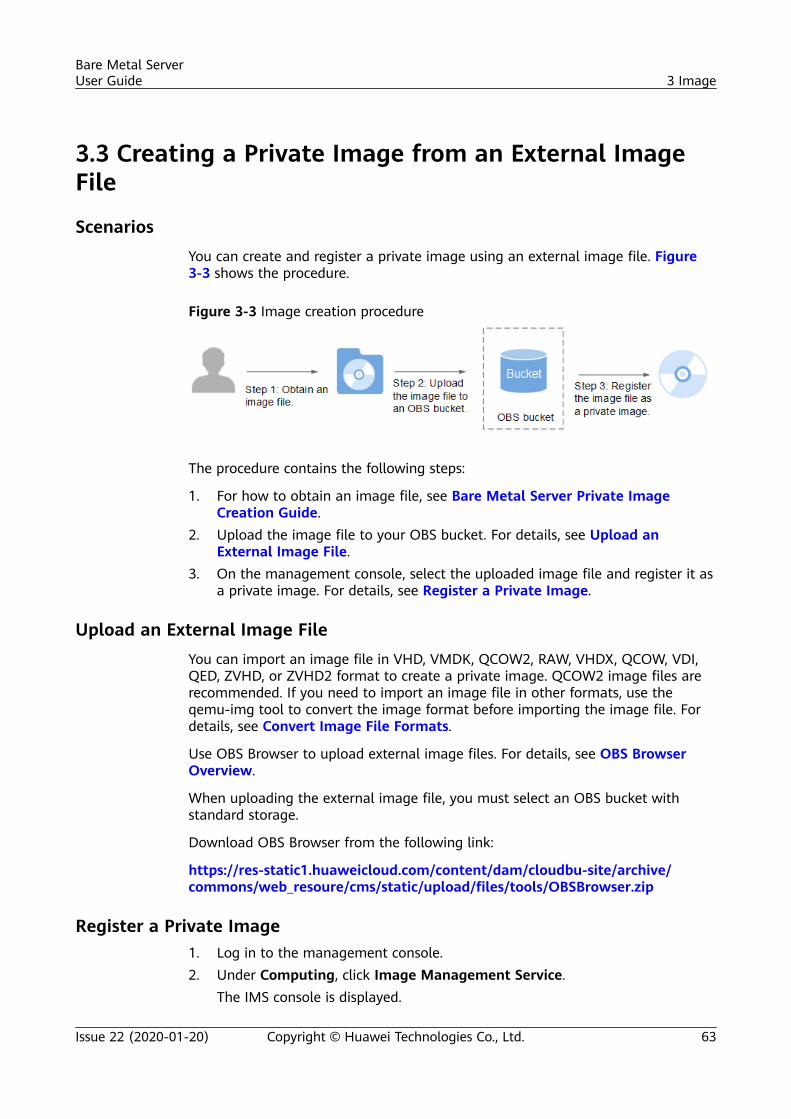
3.3 Creating a Private Image from an External ImageFile
ScenariosYou can create and register a private image using an external image file. Figure3-3 shows the procedure.
Figure 3-3 Image creation procedure
The procedure contains the following steps:
1. For how to obtain an image file, see Bare Metal Server Private ImageCreation Guide.
2. Upload the image file to your OBS bucket. For details, see Upload anExternal Image File.
3. On the management console, select the uploaded image file and register it asa private image. For details, see Register a Private Image.
Upload an External Image FileYou can import an image file in VHD, VMDK, QCOW2, RAW, VHDX, QCOW, VDI,QED, ZVHD, or ZVHD2 format to create a private image. QCOW2 image files arerecommended. If you need to import an image file in other formats, use theqemu-img tool to convert the image format before importing the image file. Fordetails, see Convert Image File Formats.
Use OBS Browser to upload external image files. For details, see OBS BrowserOverview.
When uploading the external image file, you must select an OBS bucket withstandard storage.
Download OBS Browser from the following link:
https://res-static1.huaweicloud.com/content/dam/cloudbu-site/archive/commons/web_resoure/cms/static/upload/files/tools/OBSBrowser.zip
Register a Private Image1. Log in to the management console.2. Under Computing, click Image Management Service.
The IMS console is displayed.
Bare Metal ServerUser Guide 3 Image
Issue 22 (2020-01-20) Copyright © Huawei Technologies Co., Ltd. 63
3. Click Create Private Image in the upper right corner and configure thefollowing parameters:Image Type and Source– Type: Select System disk image.– Source: Select Image file.
In the bucket list, select the bucket that stores the image file and selectthe image file.
Image Information– Function: Select BMS system disk image.
Ensure that you have completed initialization configuration on the imagefile by following the instructions in Bare Metal Server Private ImageCreation Guide.
– OS: (Optional) Select the OS of the image file.To ensure that the image can be created and used properly, select the OSconsistent with that of the image file.
– System Disk (GB): Set the system disk size. You are advised to set thevalue to the image system disk size plus 2 GB.
– Name: Enter a name for the image to be created. The value can containonly letters, digits, spaces, hyphens (-), underscores (_), and periods (.),and cannot start or end with a space.
– Enterprise Project: Select an enterprise project from the drop-down list.This parameter is available only when you have enabled the enterpriseproject function, or your account is an enterprise account. To enable thisfunction, contact your customer manager.
– Tag: (Optional) Add a tag to the image to identify and manage theimage more easily.
– Description: (Optional) Enter description of the image.4. Click Next.
On the displayed page, confirm the specifications and click Submit.
The time required for registering a private image varies depending on the size of theimage file.
5. The page that contains private images is displayed. The private image is beingcreated. After its status changes to Normal, the image is registeredsuccessfully.
Follow-up OperationsYou can use the private image to create a BMS by following the instructions inCreating a BMS Using a Private Image.
3.4 Convert Image File Formats
ScenariosThe open-source tool qemu-img is provided for you to convert image file formats.
Bare Metal ServerUser Guide 3 Image
Issue 22 (2020-01-20) Copyright © Huawei Technologies Co., Ltd. 64
You can import an image file in VHD, VMDK, QCOW2, RAW, VHDX, QCOW, VDI,QED, ZVHD, or ZVHD2 format to the cloud platform. QCOW2 image files arerecommended. If you need to import an image file in other formats, use theqemu-img tool to convert the image format before importing the image file. Theimage file to be imported must be a single image file. For example, you cannotuse a pre-allocated image file which depends on two files: xxxx.vmdk and xxxx-flat.vmdk. Both files can be imported to the cloud platform only after beingconverted into common VMDK or QCOW2 files.
The methods of installing qemu-img and converting image file formats may varydepending on the OS.
The qemu-img tool can do conversion between multiple formats, including VHD,VMDK, QCOW2, RAW, VHDX, QCOW, VDI, or QED. You can select the imageformat as needed.
NO TICE
● ZVHD and ZVHD2 are self-developed image file formats and cannot beidentified by qemu-img.
● When you run the command to convert the format of VHD image files, use VPCto replace VHD. Otherwise, qemu-img cannot identify the image format.
For example, to convert a CentOS 6.9 VHD image file into a QCOW2 image file,run the following command:
qemu-img convert -p -f vpc -O qcow2 centos6.9.vhd centos6.9.qcow2
Windows1. Install qemu-img.
a. Download the qemu-img installation package from https://qemu.weilnetz.de/w64/.
b. Double-click the setup file to install qemu-img in D:\Program Files\qemu (an example installation path).
2. Configure environment variables.
a. Choose Start > Computer and right-click Properties.
b. Click Advanced system settings.
c. In the System Properties dialog box, click Advanced > EnvironmentVariables.
d. In the Environment Variables dialog box, search for Path in the SystemVariable area and click Edit. Add D:\Program Files\qemu to VariableValue. Use a semicolon (;) to separate every two variable values.
If Path does not exist, add it and set its value to D:\Program Files\qemu.
e. Click OK.
3. Verify the installation.
Bare Metal ServerUser Guide 3 Image
Issue 22 (2020-01-20) Copyright © Huawei Technologies Co., Ltd. 65
Choose Start > Run, enter cmd, and press Enter. In the cmd window, enterqemu-img --help. If the qemu-img version information is contained in thecommand output, the installation is successful.
4. Convert the image format.
a. In the cmd window, run the following commands to switch to D:\Program Files\qemu:d:cd D:\Program Files\qemu
b. Run the following command to convert the image file format from VMDKto QCOW2:qemu-img convert -p -f vmdk -O qcow2 centos6.9-flat.vmdkcentos6.9.qcow2The parameters are described as follows:
▪ -p indicates the image conversion progress.
▪ -f indicates the source image format.
▪ The part following -O (which must be in upper case) consists of therequired format, source image file, and target image file.
After the conversion is complete, the target image file is displayed in thedirectory where the source image file is located.The following information is displayed:# qemu-img convert -p -f vmdk -O qcow2 centos6.9-flat.vmdk centos6.9.qcow2 (100.00/100%)
c. Run the following command to query details about the converted imagefile in QCOW2 format:qemu-img info centos6.9.qcow2The following information is displayed:# qemu-img info centos6.9.qcow2image: centos6.9.qcow2file format: qcow2virtual size: 1.0G (1073741824 bytes)disk size: 200Kcluster_size: 65536Format specific information: compat: 1.1 lazy refcounts: false
Linux1. Install qemu-img.
– For Ubuntu or Debian, run the following command:apt install qemu-img
– For CentOS, Red Hat, or Oracle, run the following command:yum install qemu-img
– For SUSE or openSUSE, run the following command:zypper install qemu-img
2. Run the following command to check whether the installation is successful:
Bare Metal ServerUser Guide 3 Image
Issue 22 (2020-01-20) Copyright © Huawei Technologies Co., Ltd. 66
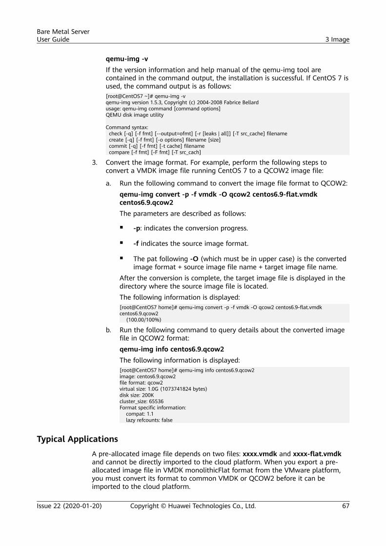
qemu-img -vIf the version information and help manual of the qemu-img tool arecontained in the command output, the installation is successful. If CentOS 7 isused, the command output is as follows:[root@CentOS7 ~]# qemu-img -vqemu-img version 1.5.3, Copyright (c) 2004-2008 Fabrice Bellardusage: qemu-img command [command options]QEMU disk image utility
Command syntax: check [-q] [-f fmt] [--output=ofmt] [-r [leaks | all]] [-T src_cache] filename create [-q] [-f fmt] [-o options] filename [size] commit [-q] [-f fmt] [-t cache] filename compare [-f fmt] [-F fmt] [-T src_cach]
3. Convert the image format. For example, perform the following steps toconvert a VMDK image file running CentOS 7 to a QCOW2 image file:
a. Run the following command to convert the image file format to QCOW2:qemu-img convert -p -f vmdk -O qcow2 centos6.9-flat.vmdkcentos6.9.qcow2The parameters are described as follows:
▪ -p: indicates the conversion progress.
▪ -f indicates the source image format.
▪ The pat following -O (which must be in upper case) is the convertedimage format + source image file name + target image file name.
After the conversion is complete, the target image file is displayed in thedirectory where the source image file is located.The following information is displayed:[root@CentOS7 home]# qemu-img convert -p -f vmdk -O qcow2 centos6.9-flat.vmdk centos6.9.qcow2 (100.00/100%)
b. Run the following command to query details about the converted imagefile in QCOW2 format:qemu-img info centos6.9.qcow2The following information is displayed:[root@CentOS7 home]# qemu-img info centos6.9.qcow2image: centos6.9.qcow2file format: qcow2virtual size: 1.0G (1073741824 bytes)disk size: 200Kcluster_size: 65536Format specific information: compat: 1.1 lazy refcounts: false
Typical Applications
A pre-allocated image file depends on two files: xxxx.vmdk and xxxx-flat.vmdkand cannot be directly imported to the cloud platform. When you export a pre-allocated image file in VMDK monolithicFlat format from the VMware platform,you must convert its format to common VMDK or QCOW2 before it can beimported to the cloud platform.
Bare Metal ServerUser Guide 3 Image
Issue 22 (2020-01-20) Copyright © Huawei Technologies Co., Ltd. 67
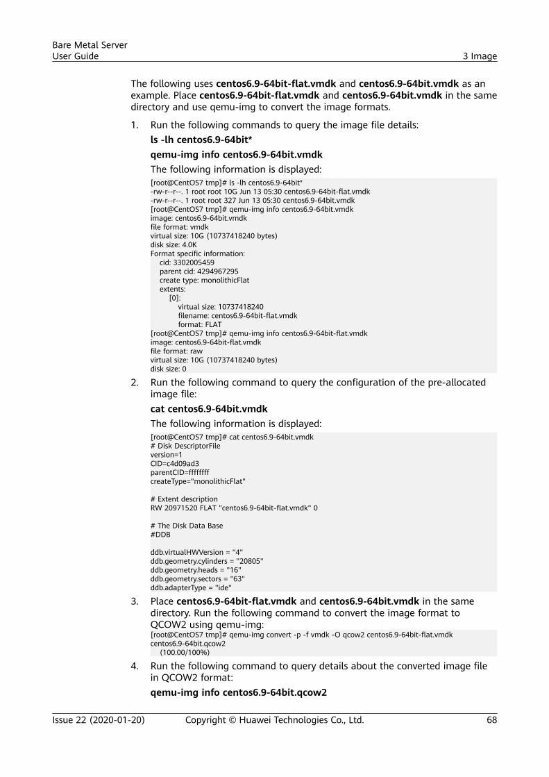
The following uses centos6.9-64bit-flat.vmdk and centos6.9-64bit.vmdk as anexample. Place centos6.9-64bit-flat.vmdk and centos6.9-64bit.vmdk in the samedirectory and use qemu-img to convert the image formats.
1. Run the following commands to query the image file details:ls -lh centos6.9-64bit*qemu-img info centos6.9-64bit.vmdkThe following information is displayed:[root@CentOS7 tmp]# ls -lh centos6.9-64bit*-rw-r--r--. 1 root root 10G Jun 13 05:30 centos6.9-64bit-flat.vmdk-rw-r--r--. 1 root root 327 Jun 13 05:30 centos6.9-64bit.vmdk[root@CentOS7 tmp]# qemu-img info centos6.9-64bit.vmdkimage: centos6.9-64bit.vmdkfile format: vmdkvirtual size: 10G (10737418240 bytes)disk size: 4.0KFormat specific information: cid: 3302005459 parent cid: 4294967295 create type: monolithicFlat extents: [0]: virtual size: 10737418240 filename: centos6.9-64bit-flat.vmdk format: FLAT[root@CentOS7 tmp]# qemu-img info centos6.9-64bit-flat.vmdkimage: centos6.9-64bit-flat.vmdkfile format: rawvirtual size: 10G (10737418240 bytes)disk size: 0
2. Run the following command to query the configuration of the pre-allocatedimage file:cat centos6.9-64bit.vmdkThe following information is displayed:[root@CentOS7 tmp]# cat centos6.9-64bit.vmdk# Disk DescriptorFileversion=1CID=c4d09ad3parentCID=ffffffffcreateType="monolithicFlat" # Extent descriptionRW 20971520 FLAT "centos6.9-64bit-flat.vmdk" 0 # The Disk Data Base#DDB ddb.virtualHWVersion = "4"ddb.geometry.cylinders = "20805"ddb.geometry.heads = "16"ddb.geometry.sectors = "63"ddb.adapterType = "ide"
3. Place centos6.9-64bit-flat.vmdk and centos6.9-64bit.vmdk in the samedirectory. Run the following command to convert the image format toQCOW2 using qemu-img:[root@CentOS7 tmp]# qemu-img convert -p -f vmdk -O qcow2 centos6.9-64bit-flat.vmdk centos6.9-64bit.qcow2 (100.00/100%)
4. Run the following command to query details about the converted image filein QCOW2 format:qemu-img info centos6.9-64bit.qcow2
Bare Metal ServerUser Guide 3 Image
Issue 22 (2020-01-20) Copyright © Huawei Technologies Co., Ltd. 68

The following information is displayed:[root@CentOS7 tmp]# qemu-img info centos6.9-64bit.qcow2image: centos6.9-64bit.qcow2file format: qcow2virtual size: 10G (10737418240 bytes)disk size: 200Kcluster_size: 65536Format specific information: compat: 1.1 lazy refcounts: false
Bare Metal ServerUser Guide 3 Image
Issue 22 (2020-01-20) Copyright © Huawei Technologies Co., Ltd. 69
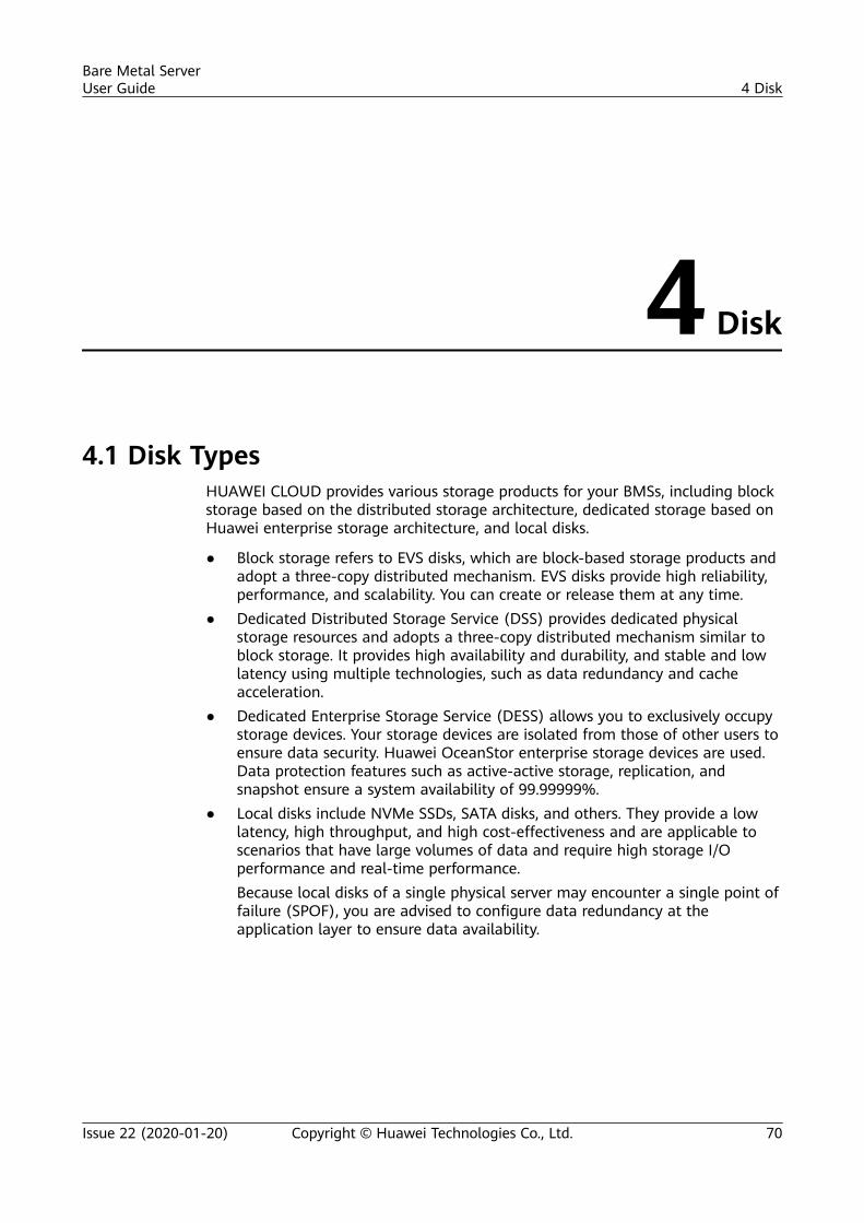
4 Disk
4.1 Disk TypesHUAWEI CLOUD provides various storage products for your BMSs, including blockstorage based on the distributed storage architecture, dedicated storage based onHuawei enterprise storage architecture, and local disks.
● Block storage refers to EVS disks, which are block-based storage products andadopt a three-copy distributed mechanism. EVS disks provide high reliability,performance, and scalability. You can create or release them at any time.
● Dedicated Distributed Storage Service (DSS) provides dedicated physicalstorage resources and adopts a three-copy distributed mechanism similar toblock storage. It provides high availability and durability, and stable and lowlatency using multiple technologies, such as data redundancy and cacheacceleration.
● Dedicated Enterprise Storage Service (DESS) allows you to exclusively occupystorage devices. Your storage devices are isolated from those of other users toensure data security. Huawei OceanStor enterprise storage devices are used.Data protection features such as active-active storage, replication, andsnapshot ensure a system availability of 99.99999%.
● Local disks include NVMe SSDs, SATA disks, and others. They provide a lowlatency, high throughput, and high cost-effectiveness and are applicable toscenarios that have large volumes of data and require high storage I/Operformance and real-time performance.Because local disks of a single physical server may encounter a single point offailure (SPOF), you are advised to configure data redundancy at theapplication layer to ensure data availability.
Bare Metal ServerUser Guide 4 Disk
Issue 22 (2020-01-20) Copyright © Huawei Technologies Co., Ltd. 70
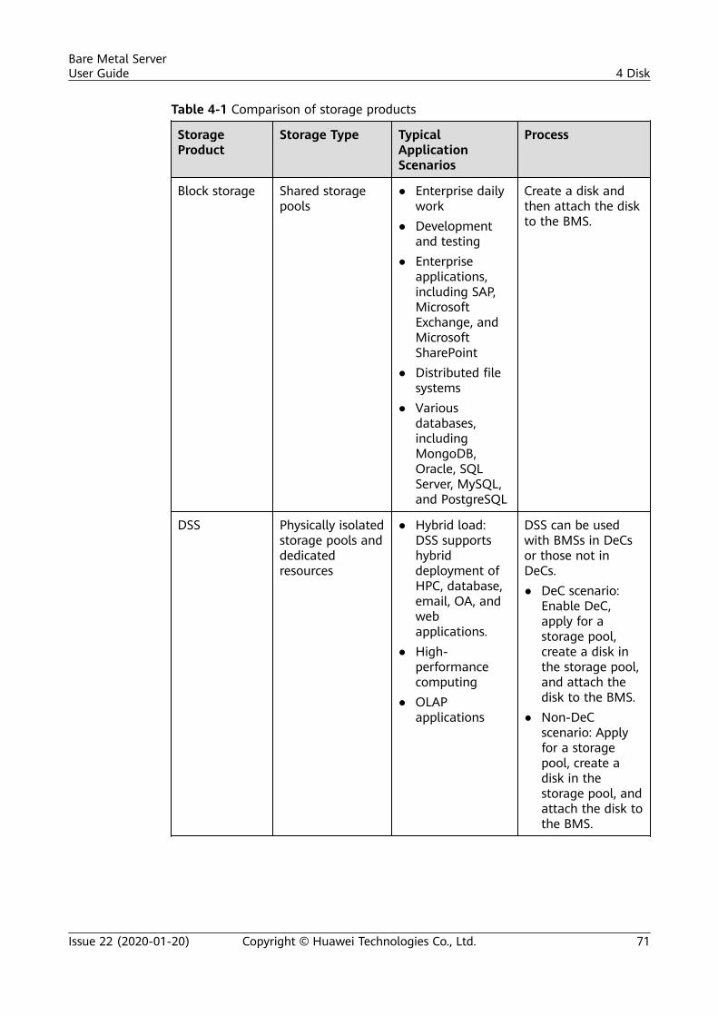
Table 4-1 Comparison of storage products
StorageProduct
Storage Type TypicalApplicationScenarios
Process
Block storage Shared storagepools
● Enterprise dailywork
● Developmentand testing
● Enterpriseapplications,including SAP,MicrosoftExchange, andMicrosoftSharePoint
● Distributed filesystems
● Variousdatabases,includingMongoDB,Oracle, SQLServer, MySQL,and PostgreSQL
Create a disk andthen attach the diskto the BMS.
DSS Physically isolatedstorage pools anddedicatedresources
● Hybrid load:DSS supportshybriddeployment ofHPC, database,email, OA, andwebapplications.
● High-performancecomputing
● OLAPapplications
DSS can be usedwith BMSs in DeCsor those not inDeCs.● DeC scenario:
Enable DeC,apply for astorage pool,create a disk inthe storage pool,and attach thedisk to the BMS.
● Non-DeCscenario: Applyfor a storagepool, create adisk in thestorage pool, andattach the disk tothe BMS.
Bare Metal ServerUser Guide 4 Disk
Issue 22 (2020-01-20) Copyright © Huawei Technologies Co., Ltd. 71
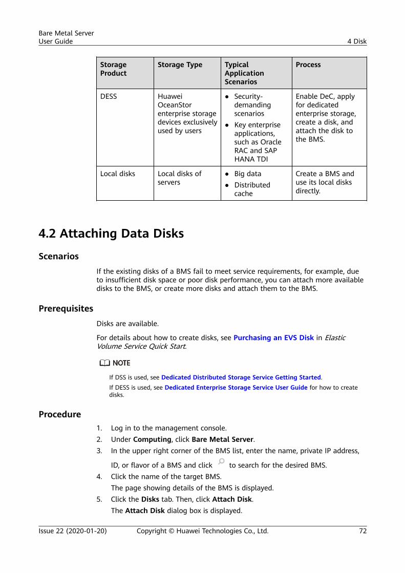
StorageProduct
Storage Type TypicalApplicationScenarios
Process
DESS HuaweiOceanStorenterprise storagedevices exclusivelyused by users
● Security-demandingscenarios
● Key enterpriseapplications,such as OracleRAC and SAPHANA TDI
Enable DeC, applyfor dedicatedenterprise storage,create a disk, andattach the disk tothe BMS.
Local disks Local disks ofservers
● Big data● Distributed
cache
Create a BMS anduse its local disksdirectly.
4.2 Attaching Data Disks
ScenariosIf the existing disks of a BMS fail to meet service requirements, for example, dueto insufficient disk space or poor disk performance, you can attach more availabledisks to the BMS, or create more disks and attach them to the BMS.
PrerequisitesDisks are available.
For details about how to create disks, see Purchasing an EVS Disk in ElasticVolume Service Quick Start.
If DSS is used, see Dedicated Distributed Storage Service Getting Started.If DESS is used, see Dedicated Enterprise Storage Service User Guide for how to createdisks.
Procedure1. Log in to the management console.2. Under Computing, click Bare Metal Server.3. In the upper right corner of the BMS list, enter the name, private IP address,
ID, or flavor of a BMS and click to search for the desired BMS.4. Click the name of the target BMS.
The page showing details of the BMS is displayed.5. Click the Disks tab. Then, click Attach Disk.
The Attach Disk dialog box is displayed.
Bare Metal ServerUser Guide 4 Disk
Issue 22 (2020-01-20) Copyright © Huawei Technologies Co., Ltd. 72
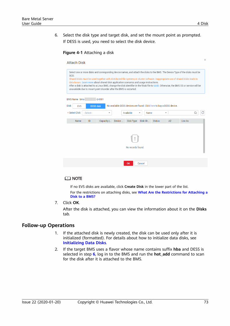
6. Select the disk type and target disk, and set the mount point as prompted.If DESS is used, you need to select the disk device.
Figure 4-1 Attaching a disk
If no EVS disks are available, click Create Disk in the lower part of the list.For the restrictions on attaching disks, see What Are the Restrictions for Attaching aDisk to a BMS?
7. Click OK.After the disk is attached, you can view the information about it on the Diskstab.
Follow-up Operations1. If the attached disk is newly created, the disk can be used only after it is
initialized (formatted). For details about how to initialize data disks, seeInitializing Data Disks.
2. If the target BMS uses a flavor whose name contains suffix hba and DESS isselected in step 6, log in to the BMS and run the hot_add command to scanfor the disk after it is attached to the BMS.
Bare Metal ServerUser Guide 4 Disk
Issue 22 (2020-01-20) Copyright © Huawei Technologies Co., Ltd. 73
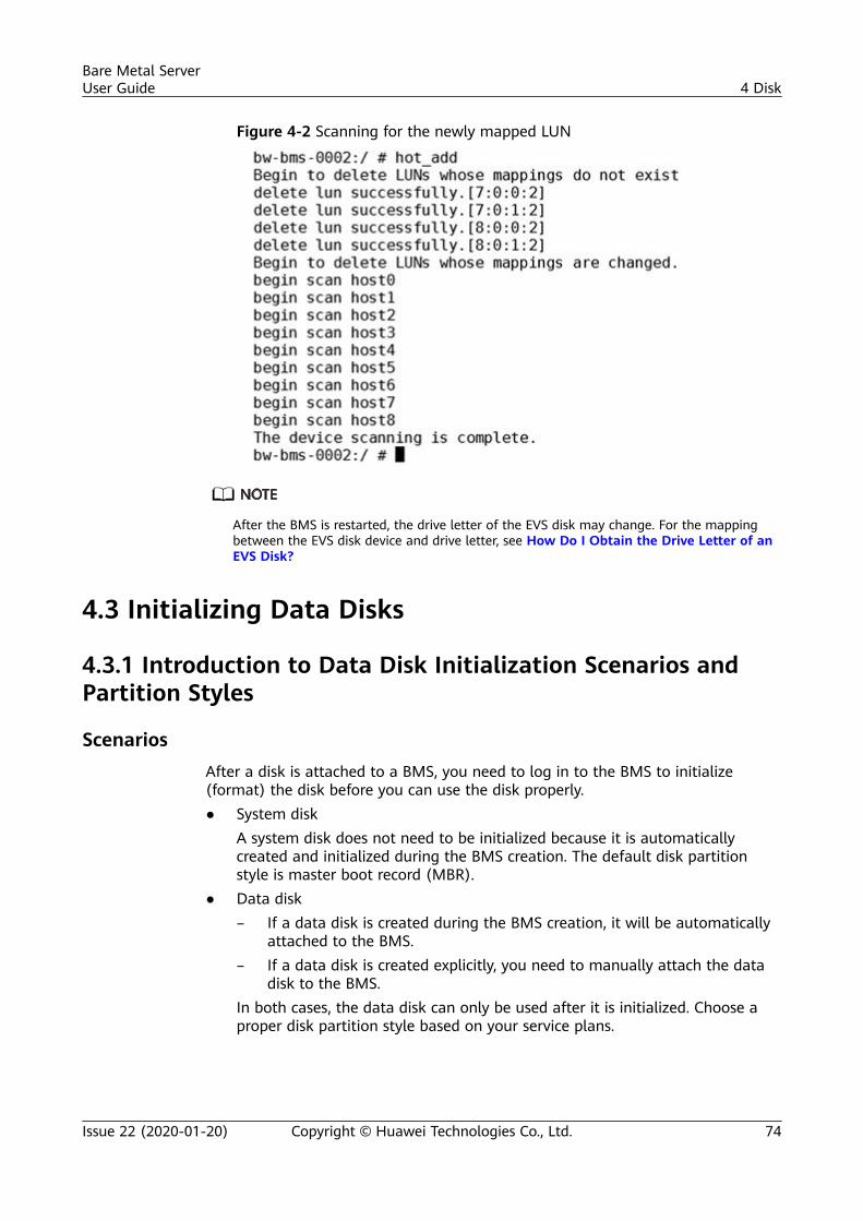
Figure 4-2 Scanning for the newly mapped LUN
After the BMS is restarted, the drive letter of the EVS disk may change. For the mappingbetween the EVS disk device and drive letter, see How Do I Obtain the Drive Letter of anEVS Disk?
4.3 Initializing Data Disks
4.3.1 Introduction to Data Disk Initialization Scenarios andPartition Styles
ScenariosAfter a disk is attached to a BMS, you need to log in to the BMS to initialize(format) the disk before you can use the disk properly.● System disk
A system disk does not need to be initialized because it is automaticallycreated and initialized during the BMS creation. The default disk partitionstyle is master boot record (MBR).
● Data disk– If a data disk is created during the BMS creation, it will be automatically
attached to the BMS.– If a data disk is created explicitly, you need to manually attach the data
disk to the BMS.In both cases, the data disk can only be used after it is initialized. Choose aproper disk partition style based on your service plans.
Bare Metal ServerUser Guide 4 Disk
Issue 22 (2020-01-20) Copyright © Huawei Technologies Co., Ltd. 74
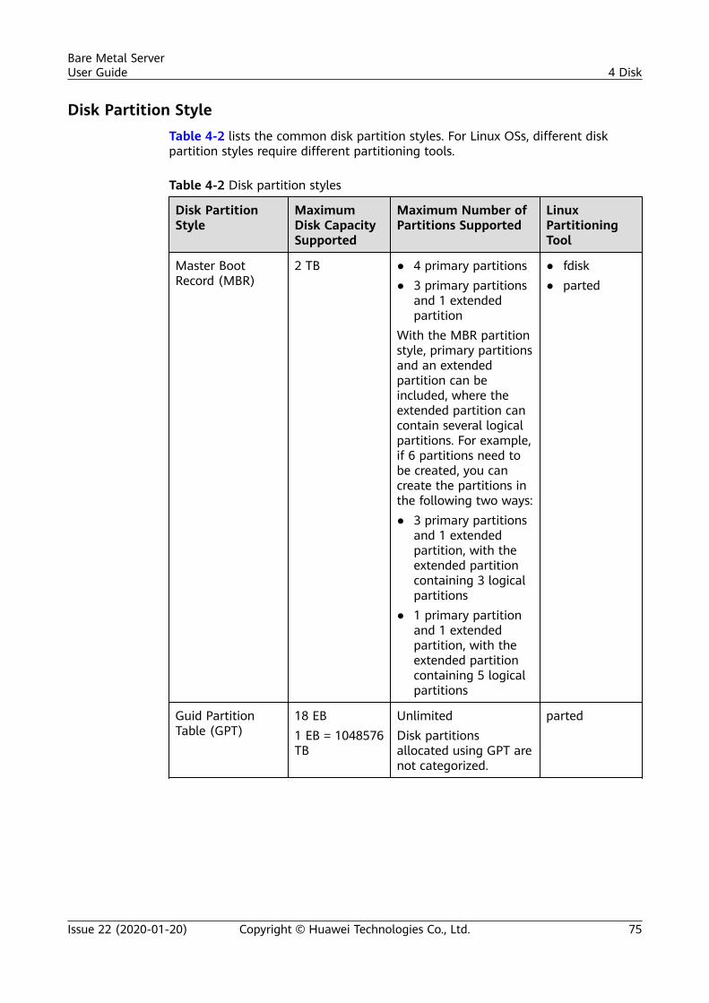
Disk Partition StyleTable 4-2 lists the common disk partition styles. For Linux OSs, different diskpartition styles require different partitioning tools.
Table 4-2 Disk partition styles
Disk PartitionStyle
MaximumDisk CapacitySupported
Maximum Number ofPartitions Supported
LinuxPartitioningTool
Master BootRecord (MBR)
2 TB ● 4 primary partitions● 3 primary partitions
and 1 extendedpartition
With the MBR partitionstyle, primary partitionsand an extendedpartition can beincluded, where theextended partition cancontain several logicalpartitions. For example,if 6 partitions need tobe created, you cancreate the partitions inthe following two ways:● 3 primary partitions
and 1 extendedpartition, with theextended partitioncontaining 3 logicalpartitions
● 1 primary partitionand 1 extendedpartition, with theextended partitioncontaining 5 logicalpartitions
● fdisk● parted
Guid PartitionTable (GPT)
18 EB1 EB = 1048576TB
UnlimitedDisk partitionsallocated using GPT arenot categorized.
parted
Bare Metal ServerUser Guide 4 Disk
Issue 22 (2020-01-20) Copyright © Huawei Technologies Co., Ltd. 75
NO TICE
The maximum disk capacity supported by MBR is 2 TB, and that supported by GPTis 18 EB. Currently, an EVS data disk supports up to 32 TB. Therefore, use the GPTpartition style if your disk capacity is greater than 2 TB.If you change the disk partition style after the disk has been used, the originaldata on the disk will be cleared. Therefore, select a proper disk partition stylewhen initializing the disk.
Partitioning Operation Guide
For a disk with less than 2 TB capacity, see one of the following topics:● Initializing a Windows Data Disk (Windows Server 2016)● Initializing a Linux Data Disk (fdisk)● Initializing a Linux Data Disk (parted)
For a disk with greater than 2 TB capacity, see one of the following topics:● Initializing a Windows Data Disk Greater Than 2 TB (Windows Server
2012)● Initializing a Linux Data Disk Greater Than 2 TB (parted)
4.3.2 Initializing a Windows Data Disk (Windows Server 2016)
Scenarios
This section uses Windows Server 2016 Standard 64bit to describe how to initializea data disk attached to a BMS running Windows.
The maximum disk capacity supported by MBR is 2 TB, and that supported by GPTis 18 EB. Therefore, use the GPT partition style if your disk capacity is greater than2 TB. For details about disk partition styles, see Introduction to Data DiskInitialization Scenarios and Partition Styles.
The method for initializing a disk varies depending on the OSs running on theBMS. This document is for reference only. For detailed operations and differences,see the product documents of the OSs running on the corresponding BMSs.
NO TICE
When using an EVS disk for the first time, if you have not initialized the disk,including creating partitions and file systems, the additional capacity added to thedisk in a later expansion operation may not be normally used.
Prerequisites● You have logged in to the BMS.● A data disk has been attached to the BMS and has not been initialized.
Bare Metal ServerUser Guide 4 Disk
Issue 22 (2020-01-20) Copyright © Huawei Technologies Co., Ltd. 76
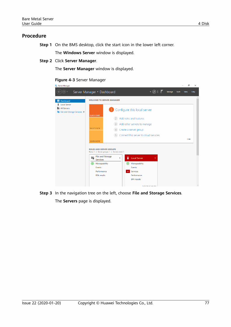
Procedure
Step 1 On the BMS desktop, click the start icon in the lower left corner.
The Windows Server window is displayed.
Step 2 Click Server Manager.
The Server Manager window is displayed.
Figure 4-3 Server Manager
Step 3 In the navigation tree on the left, choose File and Storage Services.
The Servers page is displayed.
Bare Metal ServerUser Guide 4 Disk
Issue 22 (2020-01-20) Copyright © Huawei Technologies Co., Ltd. 77
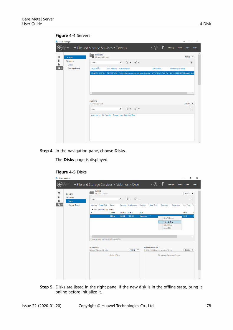
Figure 4-4 Servers
Step 4 In the navigation pane, choose Disks.
The Disks page is displayed.
Figure 4-5 Disks
Step 5 Disks are listed in the right pane. If the new disk is in the offline state, bring itonline before initialize it.
Bare Metal ServerUser Guide 4 Disk
Issue 22 (2020-01-20) Copyright © Huawei Technologies Co., Ltd. 78
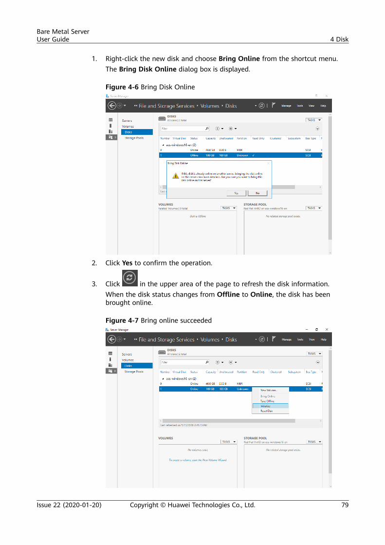
1. Right-click the new disk and choose Bring Online from the shortcut menu.The Bring Disk Online dialog box is displayed.
Figure 4-6 Bring Disk Online
2. Click Yes to confirm the operation.
3. Click in the upper area of the page to refresh the disk information.When the disk status changes from Offline to Online, the disk has beenbrought online.
Figure 4-7 Bring online succeeded
Bare Metal ServerUser Guide 4 Disk
Issue 22 (2020-01-20) Copyright © Huawei Technologies Co., Ltd. 79
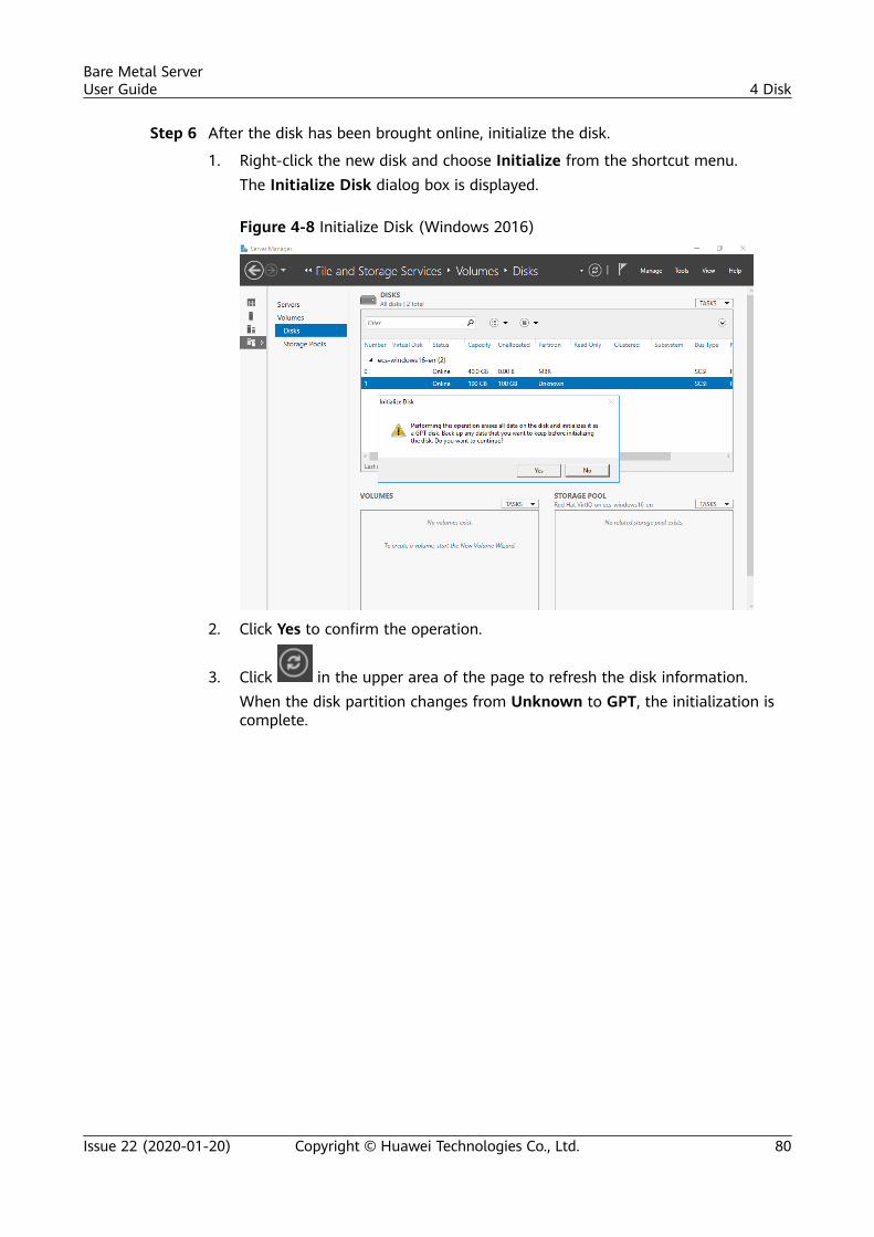
Step 6 After the disk has been brought online, initialize the disk.
1. Right-click the new disk and choose Initialize from the shortcut menu.The Initialize Disk dialog box is displayed.
Figure 4-8 Initialize Disk (Windows 2016)
2. Click Yes to confirm the operation.
3. Click in the upper area of the page to refresh the disk information.When the disk partition changes from Unknown to GPT, the initialization iscomplete.
Bare Metal ServerUser Guide 4 Disk
Issue 22 (2020-01-20) Copyright © Huawei Technologies Co., Ltd. 80
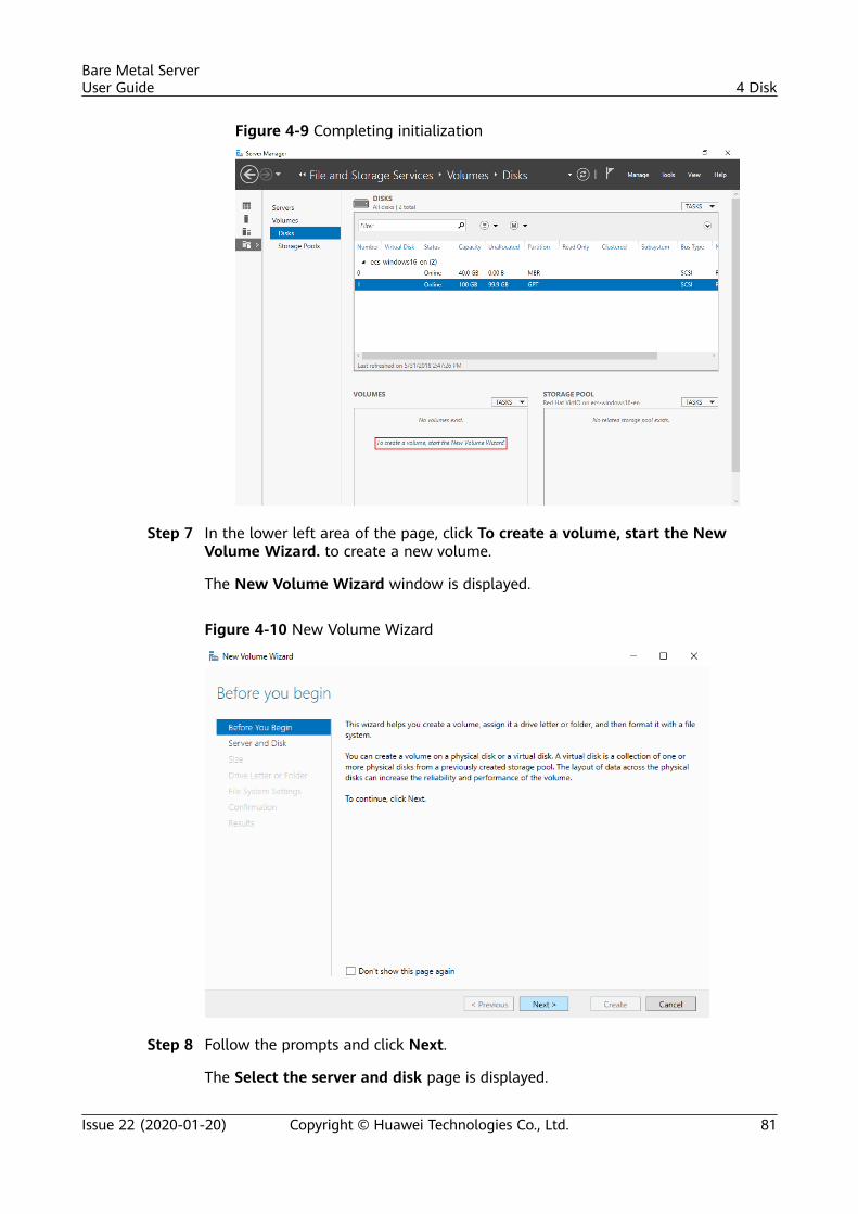
Figure 4-9 Completing initialization
Step 7 In the lower left area of the page, click To create a volume, start the NewVolume Wizard. to create a new volume.
The New Volume Wizard window is displayed.
Figure 4-10 New Volume Wizard
Step 8 Follow the prompts and click Next.
The Select the server and disk page is displayed.
Bare Metal ServerUser Guide 4 Disk
Issue 22 (2020-01-20) Copyright © Huawei Technologies Co., Ltd. 81
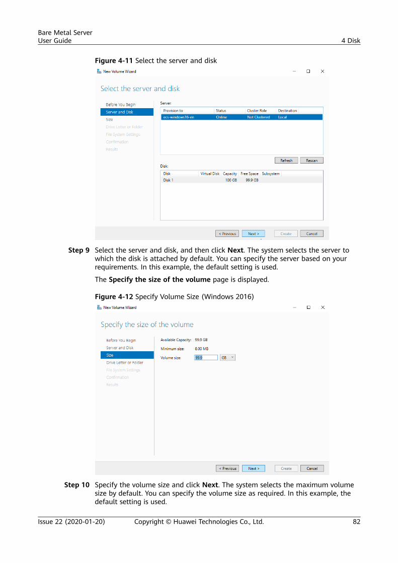
Figure 4-11 Select the server and disk
Step 9 Select the server and disk, and then click Next. The system selects the server towhich the disk is attached by default. You can specify the server based on yourrequirements. In this example, the default setting is used.
The Specify the size of the volume page is displayed.
Figure 4-12 Specify Volume Size (Windows 2016)
Step 10 Specify the volume size and click Next. The system selects the maximum volumesize by default. You can specify the volume size as required. In this example, thedefault setting is used.
Bare Metal ServerUser Guide 4 Disk
Issue 22 (2020-01-20) Copyright © Huawei Technologies Co., Ltd. 82
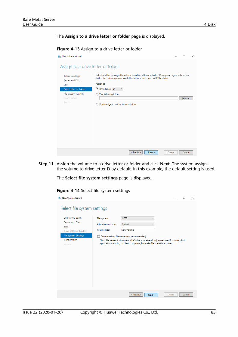
The Assign to a drive letter or folder page is displayed.
Figure 4-13 Assign to a drive letter or folder
Step 11 Assign the volume to a drive letter or folder and click Next. The system assignsthe volume to drive letter D by default. In this example, the default setting is used.
The Select file system settings page is displayed.
Figure 4-14 Select file system settings
Bare Metal ServerUser Guide 4 Disk
Issue 22 (2020-01-20) Copyright © Huawei Technologies Co., Ltd. 83
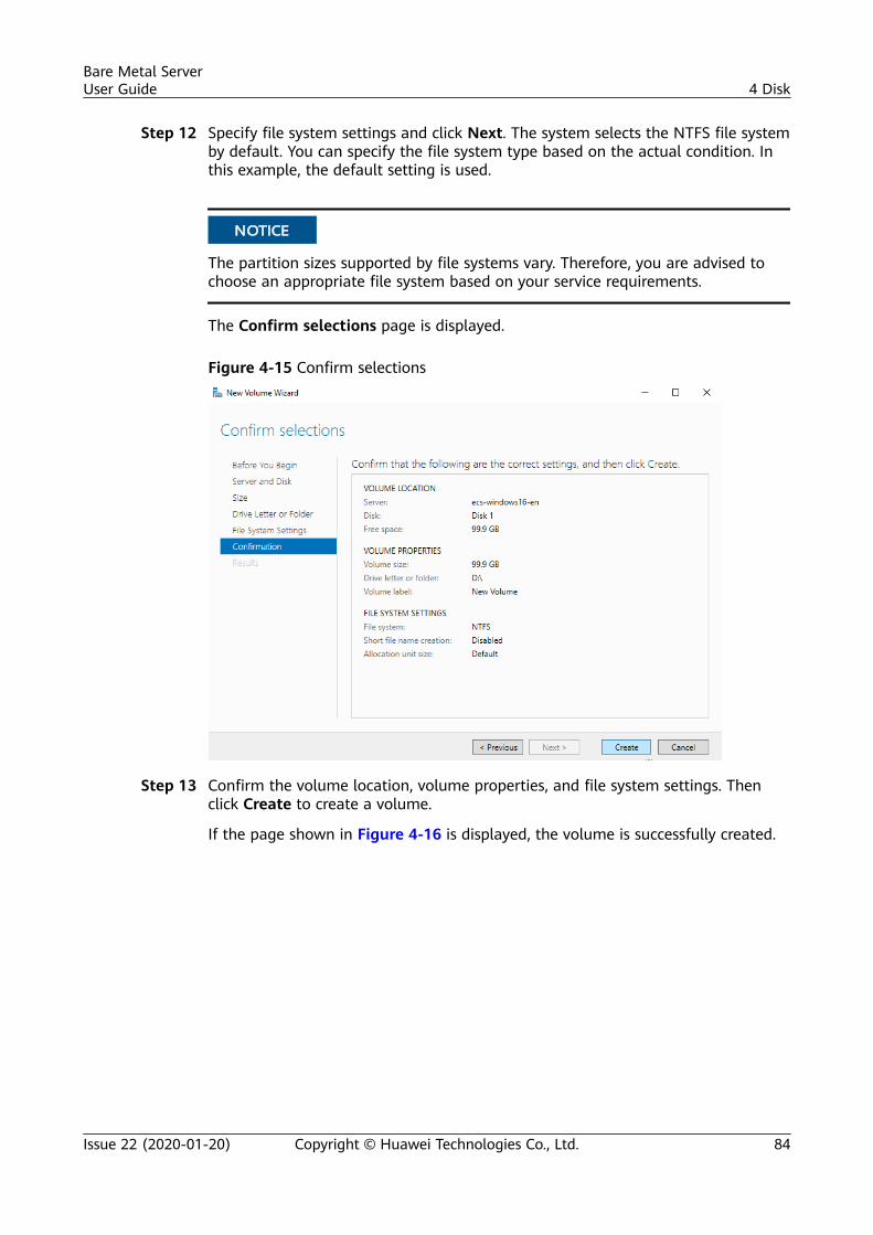
Step 12 Specify file system settings and click Next. The system selects the NTFS file systemby default. You can specify the file system type based on the actual condition. Inthis example, the default setting is used.
NO TICE
The partition sizes supported by file systems vary. Therefore, you are advised tochoose an appropriate file system based on your service requirements.
The Confirm selections page is displayed.
Figure 4-15 Confirm selections
Step 13 Confirm the volume location, volume properties, and file system settings. Thenclick Create to create a volume.
If the page shown in Figure 4-16 is displayed, the volume is successfully created.
Bare Metal ServerUser Guide 4 Disk
Issue 22 (2020-01-20) Copyright © Huawei Technologies Co., Ltd. 84
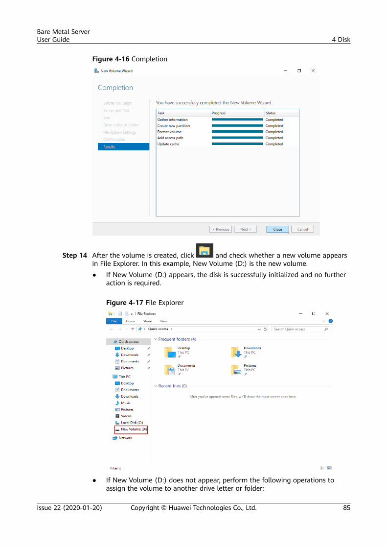
Figure 4-16 Completion
Step 14 After the volume is created, click and check whether a new volume appearsin File Explorer. In this example, New Volume (D:) is the new volume.● If New Volume (D:) appears, the disk is successfully initialized and no further
action is required.
Figure 4-17 File Explorer
● If New Volume (D:) does not appear, perform the following operations toassign the volume to another drive letter or folder:
Bare Metal ServerUser Guide 4 Disk
Issue 22 (2020-01-20) Copyright © Huawei Technologies Co., Ltd. 85
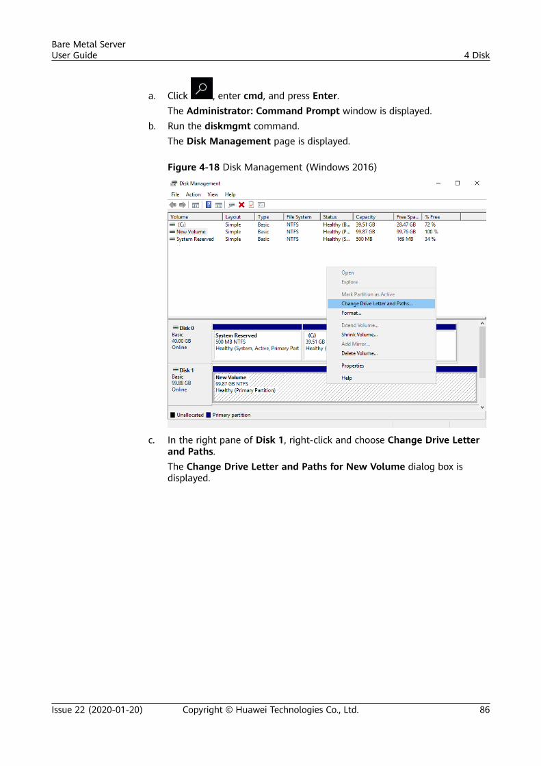
a. Click , enter cmd, and press Enter.The Administrator: Command Prompt window is displayed.
b. Run the diskmgmt command.The Disk Management page is displayed.
Figure 4-18 Disk Management (Windows 2016)
c. In the right pane of Disk 1, right-click and choose Change Drive Letterand Paths.The Change Drive Letter and Paths for New Volume dialog box isdisplayed.
Bare Metal ServerUser Guide 4 Disk
Issue 22 (2020-01-20) Copyright © Huawei Technologies Co., Ltd. 86
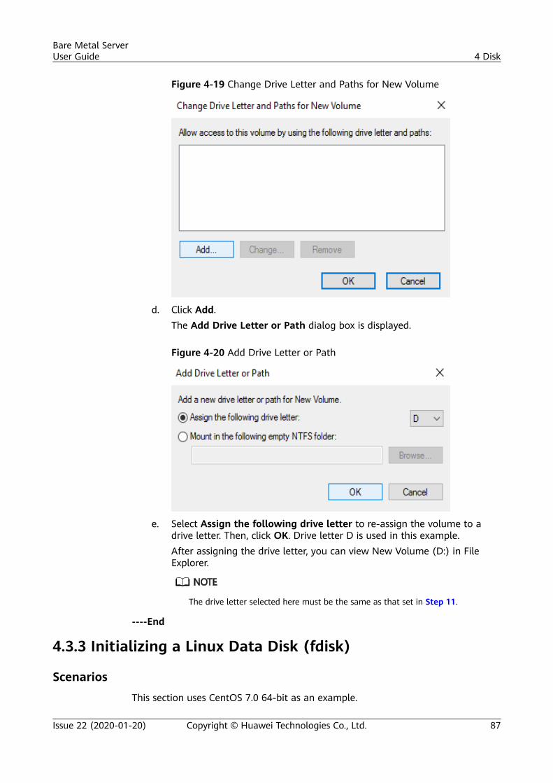
Figure 4-19 Change Drive Letter and Paths for New Volume
d. Click Add.The Add Drive Letter or Path dialog box is displayed.
Figure 4-20 Add Drive Letter or Path
e. Select Assign the following drive letter to re-assign the volume to adrive letter. Then, click OK. Drive letter D is used in this example.After assigning the drive letter, you can view New Volume (D:) in FileExplorer.
The drive letter selected here must be the same as that set in Step 11.
----End
4.3.3 Initializing a Linux Data Disk (fdisk)
ScenariosThis section uses CentOS 7.0 64-bit as an example.
Bare Metal ServerUser Guide 4 Disk
Issue 22 (2020-01-20) Copyright © Huawei Technologies Co., Ltd. 87
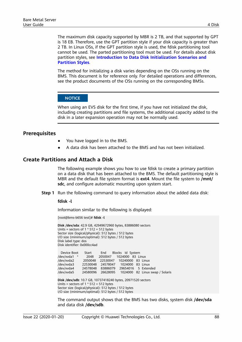
The maximum disk capacity supported by MBR is 2 TB, and that supported by GPTis 18 EB. Therefore, use the GPT partition style if your disk capacity is greater than2 TB. In Linux OSs, if the GPT partition style is used, the fdisk partitioning toolcannot be used. The parted partitioning tool must be used. For details about diskpartition styles, see Introduction to Data Disk Initialization Scenarios andPartition Styles.
The method for initializing a disk varies depending on the OSs running on theBMS. This document is for reference only. For detailed operations and differences,see the product documents of the OSs running on the corresponding BMSs.
NO TICE
When using an EVS disk for the first time, if you have not initialized the disk,including creating partitions and file systems, the additional capacity added to thedisk in a later expansion operation may not be normally used.
Prerequisites● You have logged in to the BMS.● A data disk has been attached to the BMS and has not been initialized.
Create Partitions and Attach a DiskThe following example shows you how to use fdisk to create a primary partitionon a data disk that has been attached to the BMS. The default partitioning style isMBR and the default file system format is ext4. Mount the file system to /mnt/sdc, and configure automatic mounting upon system start.
Step 1 Run the following command to query information about the added data disk:
fdisk -l
Information similar to the following is displayed:
[root@bms-b656 test]# fdisk -l
Disk /dev/sda: 42.9 GB, 42949672960 bytes, 83886080 sectorsUnits = sectors of 1 * 512 = 512 bytesSector size (logical/physical): 512 bytes / 512 bytesI/O size (minimum/optimal): 512 bytes / 512 bytesDisk label type: dosDisk identifier: 0x000cc4ad
Device Boot Start End Blocks Id System/dev/xvda1 * 2048 2050047 1024000 83 Linux/dev/xvda2 2050048 22530047 10240000 83 Linux/dev/xvda3 22530048 24578047 1024000 83 Linux/dev/xvda4 24578048 83886079 29654016 5 Extended/dev/xvda5 24580096 26628095 1024000 82 Linux swap / Solaris
Disk /dev/sdb: 10.7 GB, 10737418240 bytes, 20971520 sectorsUnits = sectors of 1 * 512 = 512 bytesSector size (logical/physical): 512 bytes / 512 bytesI/O size (minimum/optimal): 512 bytes / 512 bytes
The command output shows that the BMS has two disks, system disk /dev/sdaand data disk /dev/sdb.
Bare Metal ServerUser Guide 4 Disk
Issue 22 (2020-01-20) Copyright © Huawei Technologies Co., Ltd. 88
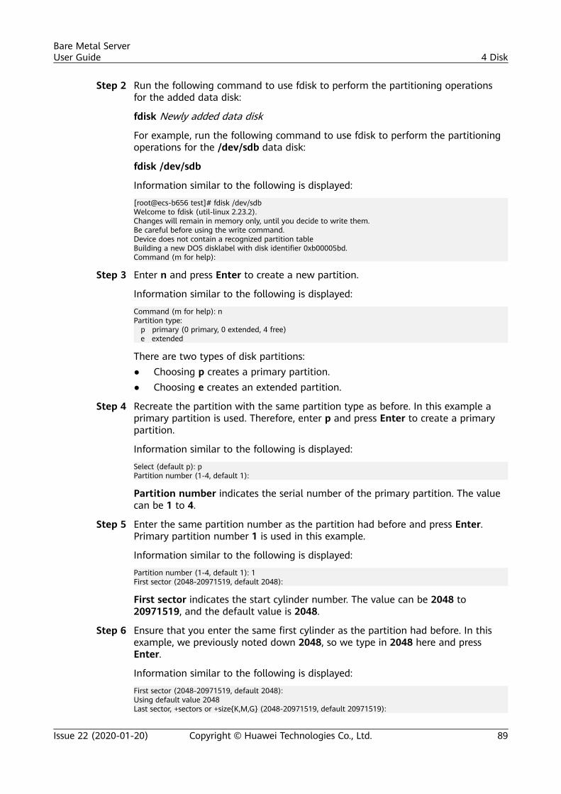
Step 2 Run the following command to use fdisk to perform the partitioning operationsfor the added data disk:
fdisk Newly added data disk
For example, run the following command to use fdisk to perform the partitioningoperations for the /dev/sdb data disk:
fdisk /dev/sdb
Information similar to the following is displayed:
[root@ecs-b656 test]# fdisk /dev/sdbWelcome to fdisk (util-linux 2.23.2).Changes will remain in memory only, until you decide to write them.Be careful before using the write command.Device does not contain a recognized partition tableBuilding a new DOS disklabel with disk identifier 0xb00005bd.Command (m for help):
Step 3 Enter n and press Enter to create a new partition.
Information similar to the following is displayed:
Command (m for help): nPartition type: p primary (0 primary, 0 extended, 4 free) e extended
There are two types of disk partitions:● Choosing p creates a primary partition.● Choosing e creates an extended partition.
Step 4 Recreate the partition with the same partition type as before. In this example aprimary partition is used. Therefore, enter p and press Enter to create a primarypartition.
Information similar to the following is displayed:
Select (default p): pPartition number (1-4, default 1):
Partition number indicates the serial number of the primary partition. The valuecan be 1 to 4.
Step 5 Enter the same partition number as the partition had before and press Enter.Primary partition number 1 is used in this example.
Information similar to the following is displayed:
Partition number (1-4, default 1): 1First sector (2048-20971519, default 2048):
First sector indicates the start cylinder number. The value can be 2048 to20971519, and the default value is 2048.
Step 6 Ensure that you enter the same first cylinder as the partition had before. In thisexample, we previously noted down 2048, so we type in 2048 here and pressEnter.
Information similar to the following is displayed:
First sector (2048-20971519, default 2048):Using default value 2048Last sector, +sectors or +size{K,M,G} (2048-20971519, default 20971519):
Bare Metal ServerUser Guide 4 Disk
Issue 22 (2020-01-20) Copyright © Huawei Technologies Co., Ltd. 89
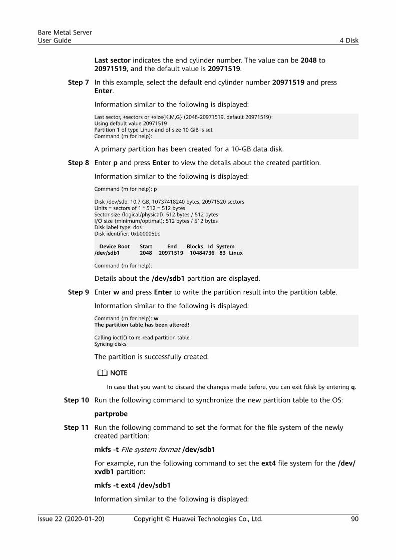
Last sector indicates the end cylinder number. The value can be 2048 to20971519, and the default value is 20971519.
Step 7 In this example, select the default end cylinder number 20971519 and pressEnter.
Information similar to the following is displayed:
Last sector, +sectors or +size{K,M,G} (2048-20971519, default 20971519):Using default value 20971519Partition 1 of type Linux and of size 10 GiB is setCommand (m for help):
A primary partition has been created for a 10-GB data disk.
Step 8 Enter p and press Enter to view the details about the created partition.
Information similar to the following is displayed:
Command (m for help): p
Disk /dev/sdb: 10.7 GB, 10737418240 bytes, 20971520 sectorsUnits = sectors of 1 * 512 = 512 bytesSector size (logical/physical): 512 bytes / 512 bytesI/O size (minimum/optimal): 512 bytes / 512 bytesDisk label type: dosDisk identifier: 0xb00005bd
Device Boot Start End Blocks Id System/dev/sdb1 2048 20971519 10484736 83 Linux
Command (m for help):
Details about the /dev/sdb1 partition are displayed.
Step 9 Enter w and press Enter to write the partition result into the partition table.
Information similar to the following is displayed:
Command (m for help): wThe partition table has been altered!
Calling ioctl() to re-read partition table.Syncing disks.
The partition is successfully created.
In case that you want to discard the changes made before, you can exit fdisk by entering q.
Step 10 Run the following command to synchronize the new partition table to the OS:
partprobe
Step 11 Run the following command to set the format for the file system of the newlycreated partition:
mkfs -t File system format /dev/sdb1
For example, run the following command to set the ext4 file system for the /dev/xvdb1 partition:
mkfs -t ext4 /dev/sdb1
Information similar to the following is displayed:
Bare Metal ServerUser Guide 4 Disk
Issue 22 (2020-01-20) Copyright © Huawei Technologies Co., Ltd. 90
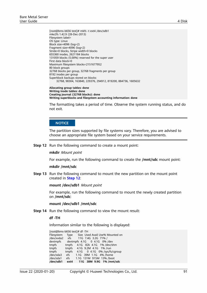
[root@bms-b656 test]# mkfs -t ext4 /dev/sdb1mke2fs 1.42.9 (28-Dec-2013)Filesystem label=OS type: LinuxBlock size=4096 (log=2)Fragment size=4096 (log=2)Stride=0 blocks, Stripe width=0 blocks655360 inodes, 2621184 blocks131059 blocks (5.00%) reserved for the super userFirst data block=0Maximum filesystem blocks=215167795280 block groups32768 blocks per group, 32768 fragments per group8192 inodes per groupSuperblock backups stored on blocks: 32768, 98304, 163840, 229376, 294912, 819200, 884736, 1605632
Allocating group tables: doneWriting inode tables: doneCreating journal (32768 blocks): doneWriting superblocks and filesystem accounting information: done
The formatting takes a period of time. Observe the system running status, and donot exit.
NO TICE
The partition sizes supported by file systems vary. Therefore, you are advised tochoose an appropriate file system based on your service requirements.
Step 12 Run the following command to create a mount point:
mkdir Mount point
For example, run the following command to create the /mnt/sdc mount point:
mkdir /mnt/sdc
Step 13 Run the following command to mount the new partition on the mount pointcreated in Step 12:
mount /dev/sdb1 Mount point
For example, run the following command to mount the newly created partitionon /mnt/sdc:
mount /dev/sdb1 /mnt/sdc
Step 14 Run the following command to view the mount result:
df -TH
Information similar to the following is displayed:
[root@bms-b656 test]# df -THFilesystem Type Size Used Avail Use% Mounted on/dev/xvda2 xfs 11G 7.4G 3.2G 71% /devtmpfs devtmpfs 4.1G 0 4.1G 0% /devtmpfs tmpfs 4.1G 82k 4.1G 1% /dev/shmtmpfs tmpfs 4.1G 9.2M 4.1G 1% /runtmpfs tmpfs 4.1G 0 4.1G 0% /sys/fs/cgroup/dev/sda3 xfs 1.1G 39M 1.1G 4% /home/dev/sda1 xfs 1.1G 131M 915M 13% /boot/dev/sdb1 ext4 11G 38M 9.9G 1% /mnt/sdc
Bare Metal ServerUser Guide 4 Disk
Issue 22 (2020-01-20) Copyright © Huawei Technologies Co., Ltd. 91
The newly created /dev/sdb1 is mounted on /mnt/sdc.
----End
Set Automatic Disk Attachment Upon BMS StartTo automatically attach a disk when a BMS starts, you should not specify itspartition, for example /dev/sdb1, in /etc/fstab. This is because the sequence ofcloud devices may change during the server start or stop process, for example,from /dev/sdb to /dev/sdc. You are advised to use the universally uniqueidentifier (UUID) in /etc/fstab to automatically attach a disk at system start.
The universally unique identifier (UUID) is the unique character string for disk partitions ina Linux system.
Step 1 Run the following command to query the partition UUID:
blkid Disk partition
For example, run the following command to query the UUID of /dev/sdb1:
blkid /dev/sdb1
Information similar to the following is displayed:
[root@bms-b656 test]# blkid /dev/sdb1/dev/sdb1: UUID="1851e23f-1c57-40ab-86bb-5fc5fc606ffa" TYPE="ext4"
The UUID of /dev/sdb1 is displayed.
Step 2 Run the following command to open the fstab file using the vi editor:
vi /etc/fstab
Step 3 Press i to enter the editing mode.
Step 4 Move the cursor to the end of the file and press Enter. Then add the followinginformation:UUID=1851e23f-1c57-40ab-86bb-5fc5fc606ffa /mnt/sdc ext4 defaults 0 2
Step 5 Press Esc, enter :wq, and press Enter.
The system saves the configurations and exits the vi editor.
----End
4.3.4 Initializing a Linux Data Disk (parted)
ScenariosThis section uses CentOS 7.0 64-bit as an example to describe how to initialize adata disk attached to a BMS running Linux and use parted to partition the datadisk.
The maximum disk capacity supported by MBR is 2 TB, and that supported by GPTis 18 EB. Therefore, use the GPT partition style if your disk capacity is greater than2 TB. In Linux OSs, if the GPT partition style is used, the fdisk partitioning toolcannot be used. The parted partitioning tool must be used. For details about disk
Bare Metal ServerUser Guide 4 Disk
Issue 22 (2020-01-20) Copyright © Huawei Technologies Co., Ltd. 92
partition styles, see Introduction to Data Disk Initialization Scenarios andPartition Styles.
The method for initializing a disk varies depending on the OSs running on theBMS. This document is for reference only. For detailed operations and differences,see the product documents of the OSs running on the corresponding BMSs.
NO TICE
When using an EVS disk for the first time, if you have not initialized the disk,including creating partitions and file systems, the additional capacity added to thedisk in a later expansion operation may not be normally used.
Prerequisites● You have logged in to the BMS.● A data disk has been attached to the BMS and has not been initialized.
Creating Partitions and Mounting a DiskThe following example shows you how to use parted to create a partition on anew data disk that has been attached to the BMS. The default partitioning style isGPT and the default file system format is ext4. Mount the file system to /mnt/sdc, and configure automatic mounting upon system start.
Step 1 Run the following command to query information about the added data disk:
lsblk
Information similar to the following is displayed:
[root@bms-centos-70 linux]# lsblkNAME MAJ:MIN RM SIZE RO TYPE MOUNTPOINTsda 202:0 0 40G 0 disk ├─sda1 202:1 0 4G 0 part [SWAP]└─sda2 202:2 0 36G 0 part /sdb 202:16 0 10G 0 disk
The command output shows that the BMS has two disks, system disk /dev/sdaand data disk /dev/sdb.
Step 2 Run the following command to enter parted to partition the added data disk:
parted Added data disk
For example, run the following command to use fdisk to perform the partitioningoperations for the /dev/sdb data disk:
parted /dev/sdb
Information similar to the following is displayed:
[root@bms-centos-70 linux]# parted /dev/sdbGNU Parted 3.1Using /dev/sdbWelcome to GNU Parted! Type 'help' to view a list of commands.
Step 3 Enter p and press Enter to view the current disk partition style.
Bare Metal ServerUser Guide 4 Disk
Issue 22 (2020-01-20) Copyright © Huawei Technologies Co., Ltd. 93
Information similar to the following is displayed:
(parted) pError: /dev/sdb: unrecognised disk labelModel: Xen Virtual Block Device (xvd) Disk /dev/sdb: 10.7GBSector size (logical/physical): 512B/512BPartition Table: unknownDisk Flags:
In the command output, the Partition Table value is unknown, indicating thatthe disk partition style is unknown.
Step 4 Run the following command to set the disk partition style:
mklabel Disk partition style
For example, run the following command to set the partition style to GPT: (Diskpartition styles include MBR and GPT.)
mklabel gpt
NO TICE
The maximum disk capacity supported by MBR is 2 TB, and that supported by GPTis 18 EB. Because a data disk currently supports up to 32 TB, use the GPT partitionstyle if your disk capacity is larger than 2 TB.If you change the disk partition style after the disk has been used, the data on thedisk will be cleared. Therefore, select a proper disk partition style when initializingthe disk.
Step 5 Enter p and press Enter to view the disk partition style.
Information similar to the following is displayed:
(parted) mklabel gpt (parted) p Model: Xen Virtual Block Device (xvd)Disk /dev/sdb: 20971520sSector size (logical/physical): 512B/512BPartition Table: gptDisk Flags:
Number Start End Size File system Name Flags
Step 6 Enter unit s and press Enter to set the measurement unit of the disk to sectornumbers.
Step 7 Enter mkpart opt 2048s 100% and press Enter.
In this example, one partition is created for the added data disk. Variable 2048sindicates the disk start capacity, and variable 100% indicates the disk end capacity.The two values are used for reference only. You can determine the number ofpartitions and the partition capacity based on your service requirements.
Information similar to the following is displayed:(parted) mkpart opt 2048s 100%Warning: The resulting partition is not properly aligned for best performance.Ignore/Cancel? Ignore
Bare Metal ServerUser Guide 4 Disk
Issue 22 (2020-01-20) Copyright © Huawei Technologies Co., Ltd. 94
If the preceding warning message is displayed, enter Ignore to ignore theperformance warning.
Step 8 Enter p and press Enter to view the details about the created partition.
Information similar to the following is displayed:
(parted) p Model: Xen Virtual Block Device (xvd)Disk /dev/sdb: 20971520sSector size (logical/physical): 512B/512BPartition Table: gptDisk Flags:
Number Start End Size File system Name Flags 1 2048s 20969471s 20967424s opt
Details about the /dev/sdb1 partition are displayed.
Step 9 Enter q and press Enter to exit parted.
Step 10 Run the following command to view the disk partition information:
lsblk
Information similar to the following is displayed:
[root@bms-centos-70 linux]# lsblk NAME MAJ:MIN RM SIZE RO TYPE MOUNTPOINTsda 202:0 0 40G 0 disk ├─sda1 202:1 0 4G 0 part [SWAP]└─sda2 202:2 0 36G 0 part /sdb 202:16 0 100G 0 disk └─sdb1 202:17 0 100G 0 part
In the command output, /dev/sdb1 is the partition you created.
Step 11 Run the following command to set the format for the file system of the newlycreated partition:
mkfs -t File system format /dev/sdb1
For example, run the following command to set the ext4 file system for the /dev/xvdb1 partition:
mkfs -t ext4 /dev/sdb1
Information similar to the following is displayed:
[root@bms-centos-70 linux]# mkfs -t ext4 /dev/sdb1mke2fs 1.42.9 (28-Dec-2013)Filesystem label=OS type: LinuxBlock size=4096 (log=2)Fragment size=4096 (log=2)Stride=0 blocks, Stripe width=0 blocks655360 inodes, 2620928 blocks131046 blocks (5.00%) reserved for the super userFirst data block=0Maximum filesystem blocks=215167792580 block groups32768 blocks per group, 32768 fragments per group8192 inodes per groupSuperblock backups stored on blocks: 32768, 98304, 163840, 229376, 294912, 819200, 884736, 1605632
Allocating group tables: done
Bare Metal ServerUser Guide 4 Disk
Issue 22 (2020-01-20) Copyright © Huawei Technologies Co., Ltd. 95
Writing inode tables: done Creating journal (32768 blocks): doneWriting superblocks and filesystem accounting information: done
The formatting takes a period of time. Observe the system running status and donot exit.
NO TICE
The partition sizes supported by file systems vary. Therefore, you are advised tochoose an appropriate file system based on your service requirements.
Step 12 Run the following command to create a mount point:
mkdir Mount point
For example, run the following command to create the /mnt/sdc mount point:
mkdir /mnt/sdc
Step 13 Run the following command to mount the new partition on the created mountpoint:
mount /dev/sdb1 Mount point
For example, run the following command to mount the newly created partitionon /mnt/sdc:
mount /dev/sdb1 /mnt/sdc
Step 14 Run the following command to view the mount result:
df -TH
Information similar to the following is displayed:
[root@bms-centos-70 linux]# df -THFilesystem Type Size Used Avail Use% Mounted on/dev/sda2 xfs 39G 4.0G 35G 11% /devtmpfs devtmpfs 946M 0 946M 0% /devtmpfs tmpfs 954M 0 954M 0% /dev/shmtmpfs tmpfs 954M 9.1M 945M 1% /runtmpfs tmpfs 954M 0 954M 0% /sys/fs/cgroup/dev/sdb1 ext4 11G 38M 101G 1% /mnt/sdc
The newly created /dev/sdb1 is mounted on /mnt/sdc.
----End
Set Automatic Disk Attachment Upon BMS Start
To automatically attach a disk when a BMS starts, you should not specify itspartition, for example /dev/sdb1, in /etc/fstab. This is because the sequence ofcloud devices may change during the server start or stop process, for example,from /dev/sdb to /dev/sdc. You are advised to use the universally uniqueidentifier (UUID) in /etc/fstab to automatically attach a disk at system start.
Bare Metal ServerUser Guide 4 Disk
Issue 22 (2020-01-20) Copyright © Huawei Technologies Co., Ltd. 96
The universally unique identifier (UUID) is the unique character string for disk partitions ina Linux system.
Step 1 Run the following command to query the partition UUID:
blkid Disk partition
For example, run the following command to query the UUID of /dev/sdb1:
blkid /dev/sdb1
Information similar to the following is displayed:
[root@bms-b656 test]# blkid /dev/sdb1/dev/sdb1: UUID="1851e23f-1c57-40ab-86bb-5fc5fc606ffa" TYPE="ext4"
The UUID of /dev/sdb1 is displayed.
Step 2 Run the following command to open the fstab file using the vi editor:
vi /etc/fstab
Step 3 Press i to enter the editing mode.
Step 4 Move the cursor to the end of the file and press Enter. Then add the followinginformation:UUID=1851e23f-1c57-40ab-86bb-5fc5fc606ffa /mnt/sdc ext4 defaults 0 2
Step 5 Press Esc, enter :wq, and press Enter.
The system saves the configurations and exits the vi editor.
----End
4.3.5 Initializing a Windows Data Disk Greater Than 2 TB(Windows Server 2012)
Scenarios
This section uses Windows Server 2012 R2 Standard 64bit to describe how toinitialize a data disk whose capacity is greater than 2 TB. In the followingoperations, the capacity of the example disk is 3 TB.
The maximum disk capacity supported by MBR is 2 TB, and that supported by GPTis 18 EB. Therefore, use the GPT partition style if your disk capacity is greater than2 TB. For details about disk partition styles, see Introduction to Data DiskInitialization Scenarios and Partition Styles.
The method for initializing a disk varies depending on the OSs running on theBMS. This document is for reference only. For detailed operations and differences,see the product documents of the OSs running on the corresponding BMSs.
Bare Metal ServerUser Guide 4 Disk
Issue 22 (2020-01-20) Copyright © Huawei Technologies Co., Ltd. 97
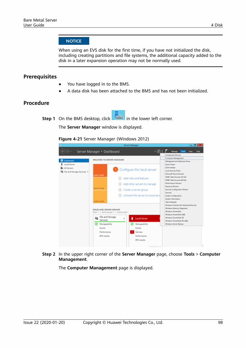
NO TICE
When using an EVS disk for the first time, if you have not initialized the disk,including creating partitions and file systems, the additional capacity added to thedisk in a later expansion operation may not be normally used.
Prerequisites● You have logged in to the BMS.● A data disk has been attached to the BMS and has not been initialized.
Procedure
Step 1 On the BMS desktop, click in the lower left corner.
The Server Manager window is displayed.
Figure 4-21 Server Manager (Windows 2012)
Step 2 In the upper right corner of the Server Manager page, choose Tools > ComputerManagement.
The Computer Management page is displayed.
Bare Metal ServerUser Guide 4 Disk
Issue 22 (2020-01-20) Copyright © Huawei Technologies Co., Ltd. 98
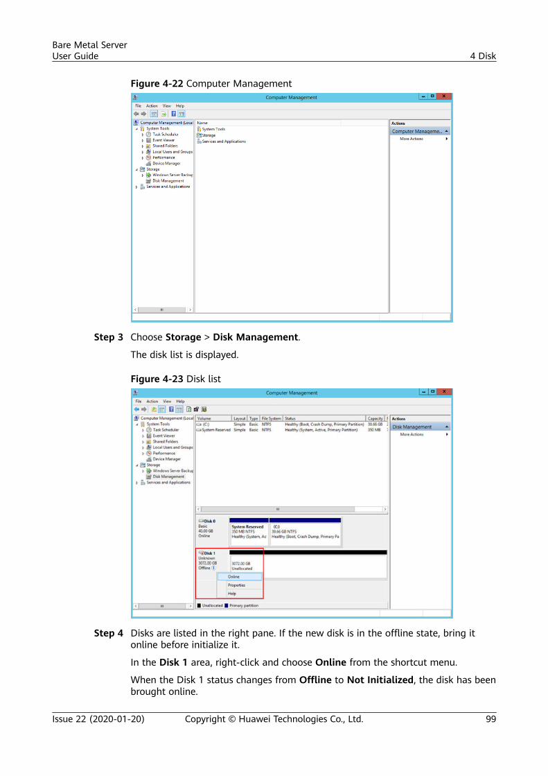
Figure 4-22 Computer Management
Step 3 Choose Storage > Disk Management.
The disk list is displayed.
Figure 4-23 Disk list
Step 4 Disks are listed in the right pane. If the new disk is in the offline state, bring itonline before initialize it.
In the Disk 1 area, right-click and choose Online from the shortcut menu.
When the Disk 1 status changes from Offline to Not Initialized, the disk has beenbrought online.
Bare Metal ServerUser Guide 4 Disk
Issue 22 (2020-01-20) Copyright © Huawei Technologies Co., Ltd. 99
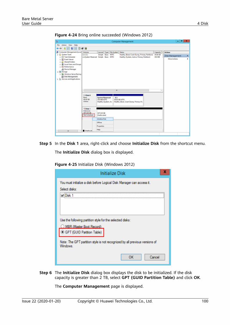
Figure 4-24 Bring online succeeded (Windows 2012)
Step 5 In the Disk 1 area, right-click and choose Initialize Disk from the shortcut menu.
The Initialize Disk dialog box is displayed.
Figure 4-25 Initialize Disk (Windows 2012)
Step 6 The Initialize Disk dialog box displays the disk to be initialized. If the diskcapacity is greater than 2 TB, select GPT (GUID Partition Table) and click OK.
The Computer Management page is displayed.
Bare Metal ServerUser Guide 4 Disk
Issue 22 (2020-01-20) Copyright © Huawei Technologies Co., Ltd. 100
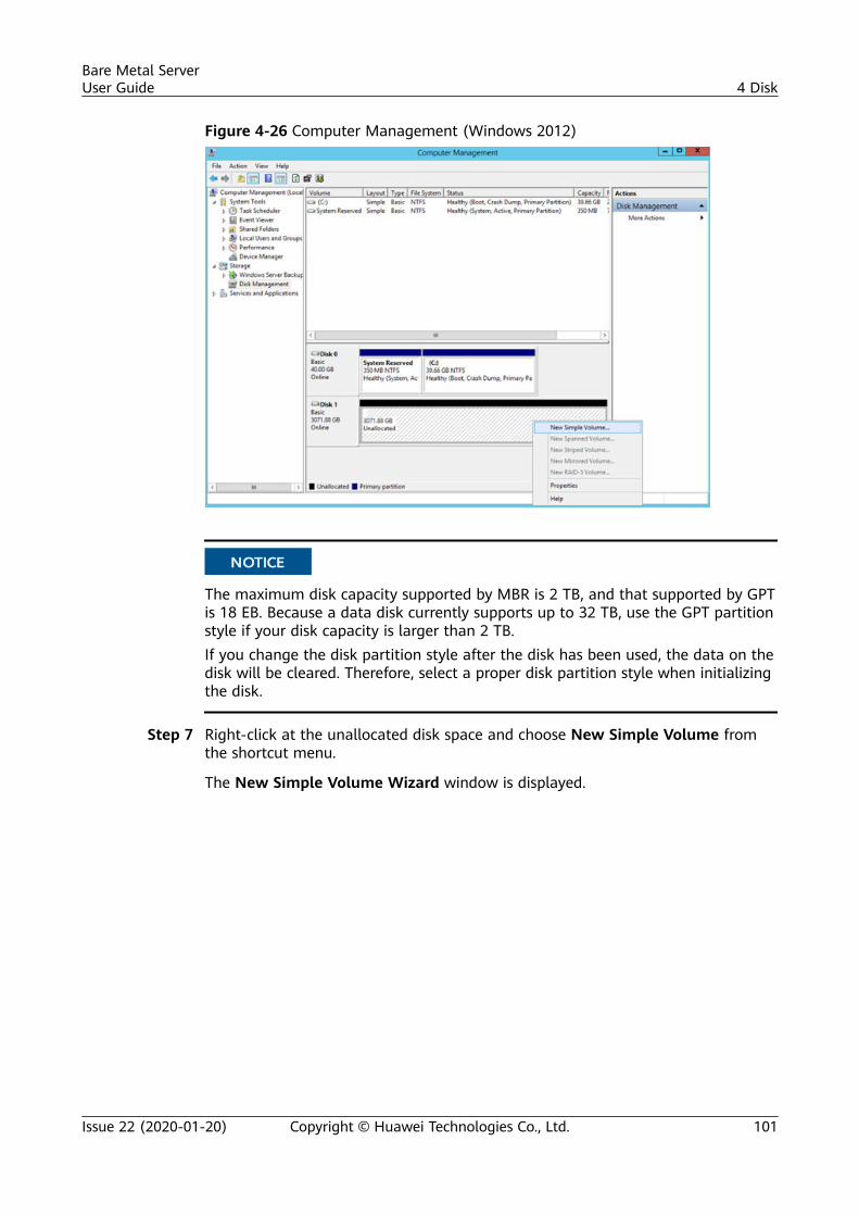
Figure 4-26 Computer Management (Windows 2012)
NO TICE
The maximum disk capacity supported by MBR is 2 TB, and that supported by GPTis 18 EB. Because a data disk currently supports up to 32 TB, use the GPT partitionstyle if your disk capacity is larger than 2 TB.If you change the disk partition style after the disk has been used, the data on thedisk will be cleared. Therefore, select a proper disk partition style when initializingthe disk.
Step 7 Right-click at the unallocated disk space and choose New Simple Volume fromthe shortcut menu.
The New Simple Volume Wizard window is displayed.
Bare Metal ServerUser Guide 4 Disk
Issue 22 (2020-01-20) Copyright © Huawei Technologies Co., Ltd. 101
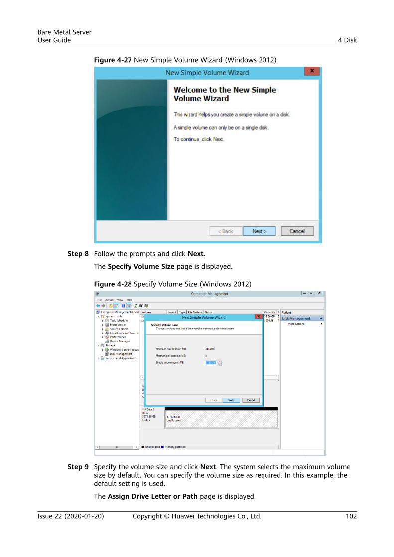
Figure 4-27 New Simple Volume Wizard (Windows 2012)
Step 8 Follow the prompts and click Next.
The Specify Volume Size page is displayed.
Figure 4-28 Specify Volume Size (Windows 2012)
Step 9 Specify the volume size and click Next. The system selects the maximum volumesize by default. You can specify the volume size as required. In this example, thedefault setting is used.
The Assign Drive Letter or Path page is displayed.
Bare Metal ServerUser Guide 4 Disk
Issue 22 (2020-01-20) Copyright © Huawei Technologies Co., Ltd. 102
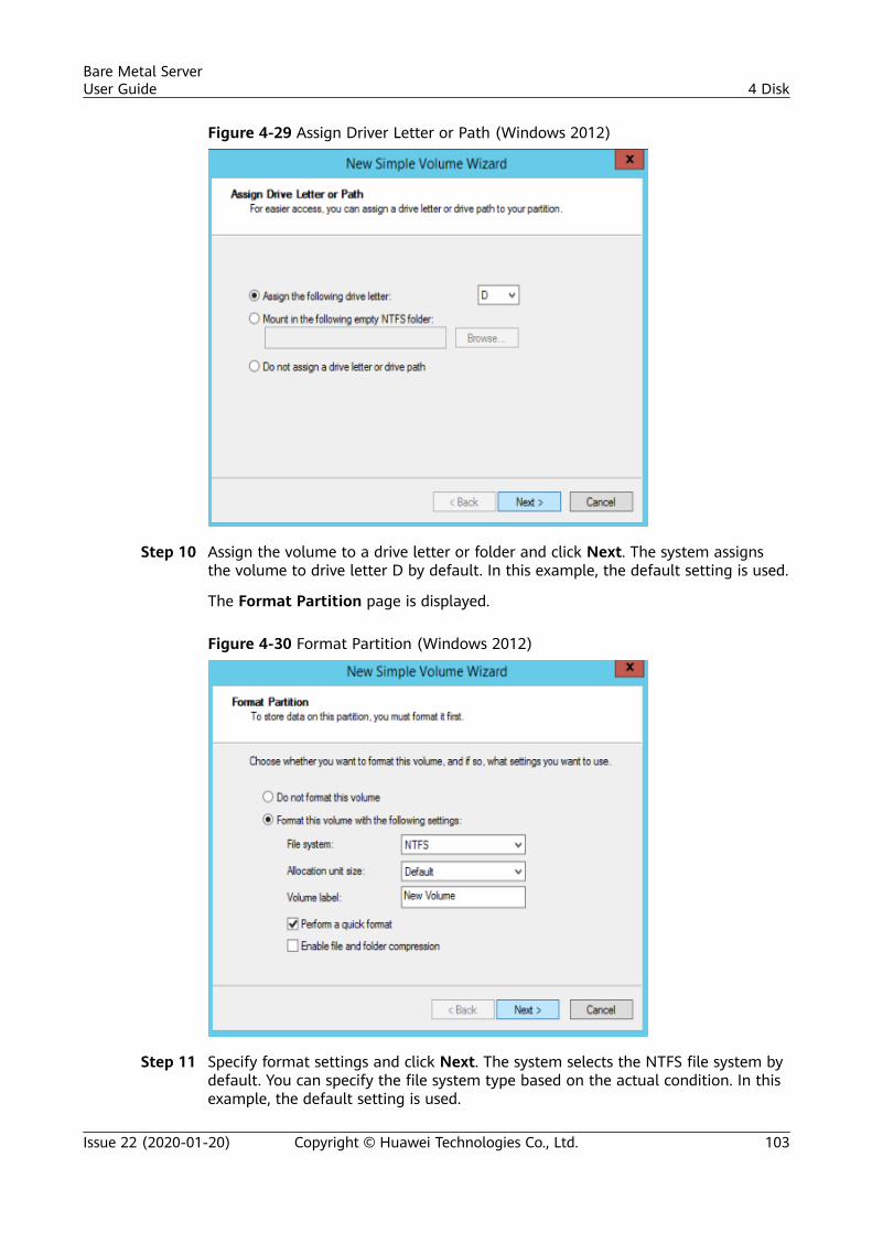
Figure 4-29 Assign Driver Letter or Path (Windows 2012)
Step 10 Assign the volume to a drive letter or folder and click Next. The system assignsthe volume to drive letter D by default. In this example, the default setting is used.
The Format Partition page is displayed.
Figure 4-30 Format Partition (Windows 2012)
Step 11 Specify format settings and click Next. The system selects the NTFS file system bydefault. You can specify the file system type based on the actual condition. In thisexample, the default setting is used.
Bare Metal ServerUser Guide 4 Disk
Issue 22 (2020-01-20) Copyright © Huawei Technologies Co., Ltd. 103
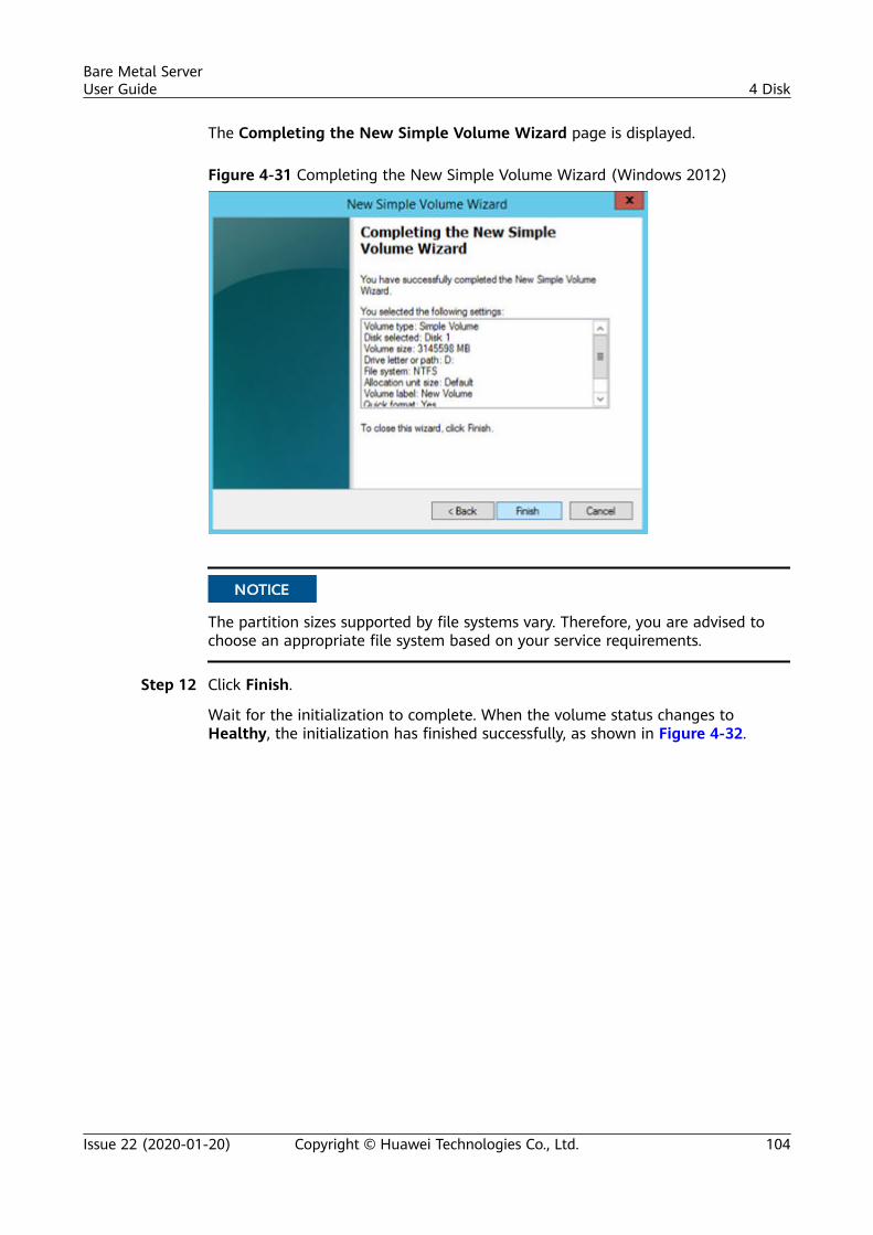
The Completing the New Simple Volume Wizard page is displayed.
Figure 4-31 Completing the New Simple Volume Wizard (Windows 2012)
NO TICE
The partition sizes supported by file systems vary. Therefore, you are advised tochoose an appropriate file system based on your service requirements.
Step 12 Click Finish.
Wait for the initialization to complete. When the volume status changes toHealthy, the initialization has finished successfully, as shown in Figure 4-32.
Bare Metal ServerUser Guide 4 Disk
Issue 22 (2020-01-20) Copyright © Huawei Technologies Co., Ltd. 104
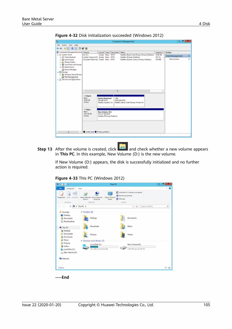
Figure 4-32 Disk initialization succeeded (Windows 2012)
Step 13 After the volume is created, click and check whether a new volume appearsin This PC. In this example, New Volume (D:) is the new volume.
If New Volume (D:) appears, the disk is successfully initialized and no furtheraction is required.
Figure 4-33 This PC (Windows 2012)
----End
Bare Metal ServerUser Guide 4 Disk
Issue 22 (2020-01-20) Copyright © Huawei Technologies Co., Ltd. 105
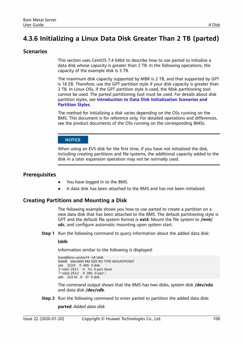
4.3.6 Initializing a Linux Data Disk Greater Than 2 TB (parted)
ScenariosThis section uses CentOS 7.4 64bit to describe how to use parted to initialize adata disk whose capacity is greater than 2 TB. In the following operations, thecapacity of the example disk is 3 TB.
The maximum disk capacity supported by MBR is 2 TB, and that supported by GPTis 18 EB. Therefore, use the GPT partition style if your disk capacity is greater than2 TB. In Linux OSs, if the GPT partition style is used, the fdisk partitioning toolcannot be used. The parted partitioning tool must be used. For details about diskpartition styles, see Introduction to Data Disk Initialization Scenarios andPartition Styles.
The method for initializing a disk varies depending on the OSs running on theBMS. This document is for reference only. For detailed operations and differences,see the product documents of the OSs running on the corresponding BMSs.
NO TICE
When using an EVS disk for the first time, if you have not initialized the disk,including creating partitions and file systems, the additional capacity added to thedisk in a later expansion operation may not be normally used.
Prerequisites● You have logged in to the BMS.● A data disk has been attached to the BMS and has not been initialized.
Creating Partitions and Mounting a DiskThe following example shows you how to use parted to create a partition on anew data disk that has been attached to the BMS. The default partitioning style isGPT and the default file system format is ext4. Mount the file system to /mnt/sdc, and configure automatic mounting upon system start.
Step 1 Run the following command to query information about the added data disk:
lsblk
Information similar to the following is displayed:
[root@bms-centos74 ~]# lsblkNAME MAJ:MIN RM SIZE RO TYPE MOUNTPOINTvda 253:0 0 40G 0 disk├─vda1 253:1 0 1G 0 part /boot└─vda2 253:2 0 39G 0 part /vdb 253:16 0 3T 0 disk
The command output shows that the BMS has two disks, system disk /dev/vdaand data disk /dev/vdb.
Step 2 Run the following command to enter parted to partition the added data disk:
parted Added data disk
Bare Metal ServerUser Guide 4 Disk
Issue 22 (2020-01-20) Copyright © Huawei Technologies Co., Ltd. 106
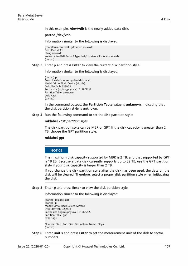
In this example, /dev/vdb is the newly added data disk.
parted /dev/vdb
Information similar to the following is displayed:
[root@bms-centos74 ~]# parted /dev/vdbGNU Parted 3.1Using /dev/vdbWelcome to GNU Parted! Type 'help' to view a list of commands.(parted)
Step 3 Enter p and press Enter to view the current disk partition style.
Information similar to the following is displayed:
(parted) pError: /dev/vdb: unrecognised disk labelModel: Virtio Block Device (virtblk)Disk /dev/vdb: 3299GBSector size (logical/physical): 512B/512BPartition Table: unknownDisk Flags:(parted)
In the command output, the Partition Table value is unknown, indicating thatthe disk partition style is unknown.
Step 4 Run the following command to set the disk partition style:
mklabel Disk partition style
The disk partition style can be MBR or GPT. If the disk capacity is greater than 2TB, choose the GPT partition style.
mklabel gpt
NO TICE
The maximum disk capacity supported by MBR is 2 TB, and that supported by GPTis 18 EB. Because a data disk currently supports up to 32 TB, use the GPT partitionstyle if your disk capacity is larger than 2 TB.If you change the disk partition style after the disk has been used, the data on thedisk will be cleared. Therefore, select a proper disk partition style when initializingthe disk.
Step 5 Enter p and press Enter to view the disk partition style.
Information similar to the following is displayed:
(parted) mklabel gpt(parted) pModel: Virtio Block Device (virtblk)Disk /dev/vdb: 3299GBSector size (logical/physical): 512B/512BPartition Table: gptDisk Flags: Number Start End Size File system Name Flags(parted)
Step 6 Enter unit s and press Enter to set the measurement unit of the disk to sectornumbers.
Bare Metal ServerUser Guide 4 Disk
Issue 22 (2020-01-20) Copyright © Huawei Technologies Co., Ltd. 107
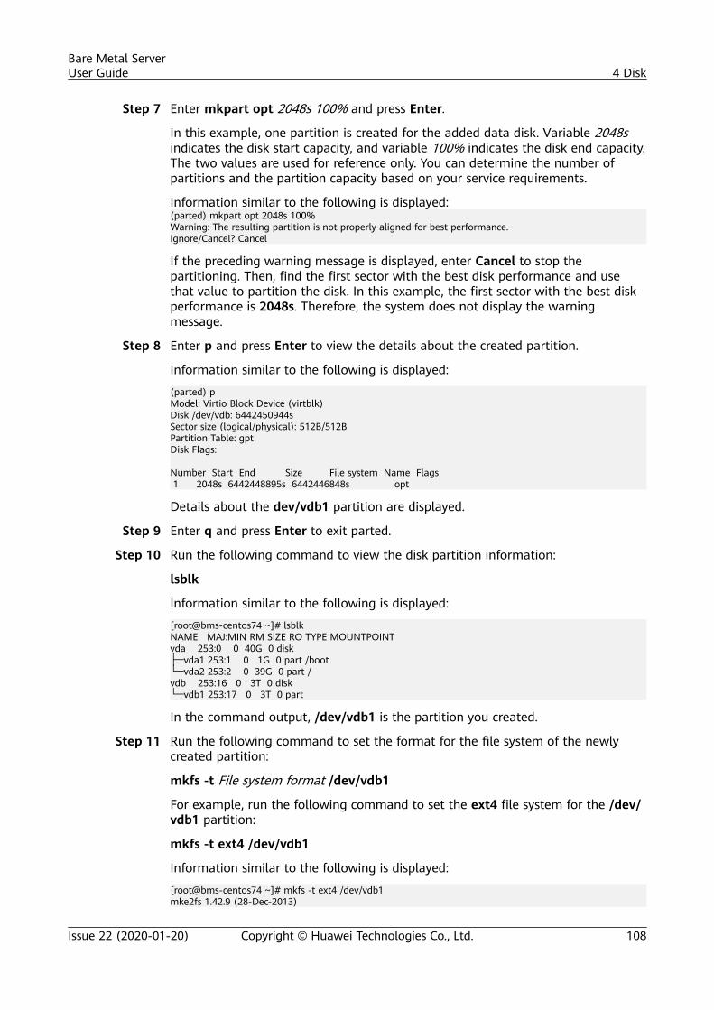
Step 7 Enter mkpart opt 2048s 100% and press Enter.
In this example, one partition is created for the added data disk. Variable 2048sindicates the disk start capacity, and variable 100% indicates the disk end capacity.The two values are used for reference only. You can determine the number ofpartitions and the partition capacity based on your service requirements.
Information similar to the following is displayed:(parted) mkpart opt 2048s 100%Warning: The resulting partition is not properly aligned for best performance.Ignore/Cancel? Cancel
If the preceding warning message is displayed, enter Cancel to stop thepartitioning. Then, find the first sector with the best disk performance and usethat value to partition the disk. In this example, the first sector with the best diskperformance is 2048s. Therefore, the system does not display the warningmessage.
Step 8 Enter p and press Enter to view the details about the created partition.
Information similar to the following is displayed:
(parted) pModel: Virtio Block Device (virtblk)Disk /dev/vdb: 6442450944sSector size (logical/physical): 512B/512BPartition Table: gptDisk Flags: Number Start End Size File system Name Flags 1 2048s 6442448895s 6442446848s opt
Details about the dev/vdb1 partition are displayed.
Step 9 Enter q and press Enter to exit parted.
Step 10 Run the following command to view the disk partition information:
lsblk
Information similar to the following is displayed:
[root@bms-centos74 ~]# lsblkNAME MAJ:MIN RM SIZE RO TYPE MOUNTPOINTvda 253:0 0 40G 0 disk├─vda1 253:1 0 1G 0 part /boot└─vda2 253:2 0 39G 0 part /vdb 253:16 0 3T 0 disk└─vdb1 253:17 0 3T 0 part
In the command output, /dev/vdb1 is the partition you created.
Step 11 Run the following command to set the format for the file system of the newlycreated partition:
mkfs -t File system format /dev/vdb1
For example, run the following command to set the ext4 file system for the /dev/vdb1 partition:
mkfs -t ext4 /dev/vdb1
Information similar to the following is displayed:
[root@bms-centos74 ~]# mkfs -t ext4 /dev/vdb1mke2fs 1.42.9 (28-Dec-2013)
Bare Metal ServerUser Guide 4 Disk
Issue 22 (2020-01-20) Copyright © Huawei Technologies Co., Ltd. 108
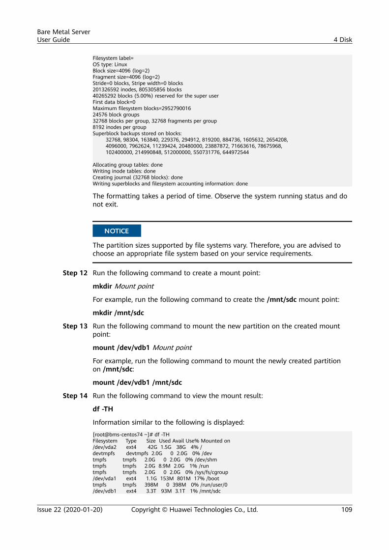
Filesystem label=OS type: LinuxBlock size=4096 (log=2)Fragment size=4096 (log=2)Stride=0 blocks, Stripe width=0 blocks201326592 inodes, 805305856 blocks40265292 blocks (5.00%) reserved for the super userFirst data block=0Maximum filesystem blocks=295279001624576 block groups32768 blocks per group, 32768 fragments per group8192 inodes per groupSuperblock backups stored on blocks: 32768, 98304, 163840, 229376, 294912, 819200, 884736, 1605632, 2654208, 4096000, 7962624, 11239424, 20480000, 23887872, 71663616, 78675968, 102400000, 214990848, 512000000, 550731776, 644972544 Allocating group tables: doneWriting inode tables: doneCreating journal (32768 blocks): doneWriting superblocks and filesystem accounting information: done
The formatting takes a period of time. Observe the system running status and donot exit.
NO TICE
The partition sizes supported by file systems vary. Therefore, you are advised tochoose an appropriate file system based on your service requirements.
Step 12 Run the following command to create a mount point:
mkdir Mount point
For example, run the following command to create the /mnt/sdc mount point:
mkdir /mnt/sdc
Step 13 Run the following command to mount the new partition on the created mountpoint:
mount /dev/vdb1 Mount point
For example, run the following command to mount the newly created partitionon /mnt/sdc:
mount /dev/vdb1 /mnt/sdc
Step 14 Run the following command to view the mount result:
df -TH
Information similar to the following is displayed:
[root@bms-centos74 ~]# df -THFilesystem Type Size Used Avail Use% Mounted on/dev/vda2 ext4 42G 1.5G 38G 4% /devtmpfs devtmpfs 2.0G 0 2.0G 0% /devtmpfs tmpfs 2.0G 0 2.0G 0% /dev/shmtmpfs tmpfs 2.0G 8.9M 2.0G 1% /runtmpfs tmpfs 2.0G 0 2.0G 0% /sys/fs/cgroup/dev/vda1 ext4 1.1G 153M 801M 17% /boottmpfs tmpfs 398M 0 398M 0% /run/user/0/dev/vdb1 ext4 3.3T 93M 3.1T 1% /mnt/sdc
Bare Metal ServerUser Guide 4 Disk
Issue 22 (2020-01-20) Copyright © Huawei Technologies Co., Ltd. 109
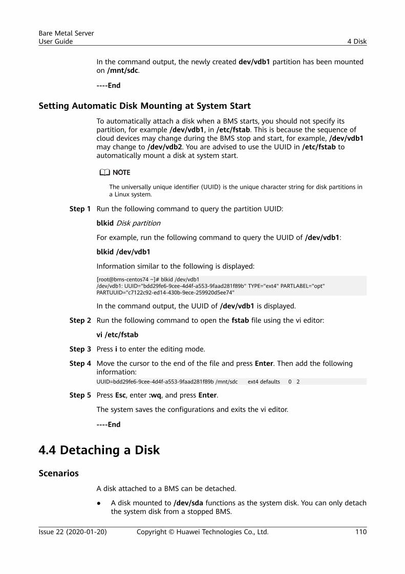
In the command output, the newly created dev/vdb1 partition has been mountedon /mnt/sdc.
----End
Setting Automatic Disk Mounting at System Start
To automatically attach a disk when a BMS starts, you should not specify itspartition, for example /dev/vdb1, in /etc/fstab. This is because the sequence ofcloud devices may change during the BMS stop and start, for example, /dev/vdb1may change to /dev/vdb2. You are advised to use the UUID in /etc/fstab toautomatically mount a disk at system start.
The universally unique identifier (UUID) is the unique character string for disk partitions ina Linux system.
Step 1 Run the following command to query the partition UUID:
blkid Disk partition
For example, run the following command to query the UUID of /dev/vdb1:
blkid /dev/vdb1
Information similar to the following is displayed:
[root@bms-centos74 ~]# blkid /dev/vdb1/dev/vdb1: UUID="bdd29fe6-9cee-4d4f-a553-9faad281f89b" TYPE="ext4" PARTLABEL="opt" PARTUUID="c7122c92-ed14-430b-9ece-259920d5ee74"
In the command output, the UUID of /dev/vdb1 is displayed.
Step 2 Run the following command to open the fstab file using the vi editor:
vi /etc/fstab
Step 3 Press i to enter the editing mode.
Step 4 Move the cursor to the end of the file and press Enter. Then add the followinginformation:UUID=bdd29fe6-9cee-4d4f-a553-9faad281f89b /mnt/sdc ext4 defaults 0 2
Step 5 Press Esc, enter :wq, and press Enter.
The system saves the configurations and exits the vi editor.
----End
4.4 Detaching a Disk
Scenarios
A disk attached to a BMS can be detached.
● A disk mounted to /dev/sda functions as the system disk. You can only detachthe system disk from a stopped BMS.
Bare Metal ServerUser Guide 4 Disk
Issue 22 (2020-01-20) Copyright © Huawei Technologies Co., Ltd. 110
● Disks mounted to a mount point other than /dev/sda function as data disksand can be detached from a running or stopped BMS.
Restrictions and Limitations● Detaching the system disk is a mission-critical operation. A BMS without the
system disk cannot start. Exercise caution when performing this operation.● Before detaching a data disk from a running Windows BMS, ensure that no
program is reading data from or writing data to the disk. Otherwise, data willbe lost.
● Before detaching a data disk from a running Linux BMS, you must log in tothe BMS and run the umount command to cancel the association betweenthe disk and the file system. In addition, ensure that no program is readingdata from or writing data to the disk. Otherwise, detaching the disk will fail.
Procedure1. Log in to the management console.2. Under Computing, click Bare Metal Server.3. Click the name of the BMS from which the disk is to be detached. The page
showing details of the BMS is displayed.4. Click the Disks tab. Locate the row containing the disk to be detached and
click Detach.
Follow-up OperationsIf the target BMS uses a flavor whose name contains suffix hba and the disk typeis DESS, log in to the BMS and run the hot_add command to scan for the diskafter it is detached from the BMS.
4.5 Expanding Disk CapacityIf a disk does not have sufficient capacity, you can expand its capacity. Both thesystem disk and data disk can be expanded. The maximum size of a system disk is1 TB. For details about how to expand the disk capacity, see Expanding theCapacity of an EVS Disk.
After the capacity expansion is successful, allocate the partition for the extendedspace of the DSS disk.
● For details about the follow-up operations after a system disk is expanded,see Performing Post-Expansion Operations for a Linux System Disk (fdisk)in Elastic Volume Service User Guide.
● For details about the follow-up operations after a data disk is expanded, seePerforming Post-Expansion Operations for a Linux SCSI Data Disk (fdisk)in Elastic Volume Service User Guide.
Bare Metal ServerUser Guide 4 Disk
Issue 22 (2020-01-20) Copyright © Huawei Technologies Co., Ltd. 111
5 Key Pair and Password
5.1 Using an SSH Key Pair
Use an SSH Key Pair
To ensure system security, you are recommended to use the key authenticationmode to authorize the user who attempts to log in to a BMS. Therefore, you mustuse an existing key pair or create a new one for remote login authentication.
● Creating a Key PairIf no key pair is available, create one that contains a public and a private keyused for login authentication. You can use either of the following methods:– Create a key pair using the management console. After the creation, the
public key is automatically stored in the system, and the private key ismanually stored in a local directory. For details, see Create a Key Pair onthe Management Console.
– Use PuTTYgen to create a key pair, and save both the public and privatekeys to the local host. For details, see Create a Key Pair UsingPuTTYgen. After the creation, import the key pair by following theinstructions provided in Import a Key Pair. Then, the key pair can beused.
PuTTYgen is a tool for generating public and private keys. You can obtain the toolfrom https://www.chiark.greenend.org.uk/~sgtatham/putty/latest.html.
● Using an existing key pairIf a key pair is available locally, for example, generated using PuTTYgen, youcan import the public key on the management console so that the systemmaintains the public key file. For details, see Import a Key Pair.
Create a Key Pair on the Management Console1. Log in to the management console.2. Under Computing, click Bare Metal Server.
Bare Metal ServerUser Guide 5 Key Pair and Password
Issue 22 (2020-01-20) Copyright © Huawei Technologies Co., Ltd. 112
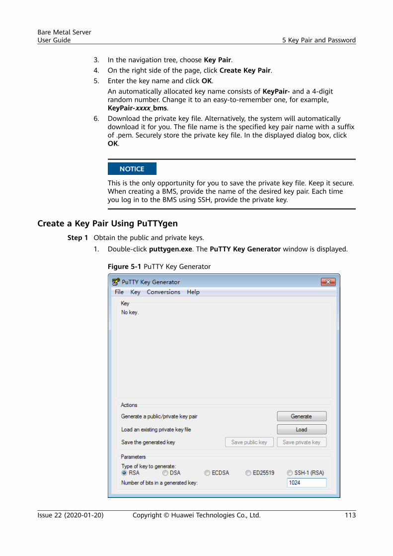
3. In the navigation tree, choose Key Pair.4. On the right side of the page, click Create Key Pair.5. Enter the key name and click OK.
An automatically allocated key name consists of KeyPair- and a 4-digitrandom number. Change it to an easy-to-remember one, for example,KeyPair-xxxx_bms.
6. Download the private key file. Alternatively, the system will automaticallydownload it for you. The file name is the specified key pair name with a suffixof .pem. Securely store the private key file. In the displayed dialog box, clickOK.
NO TICE
This is the only opportunity for you to save the private key file. Keep it secure.When creating a BMS, provide the name of the desired key pair. Each timeyou log in to the BMS using SSH, provide the private key.
Create a Key Pair Using PuTTYgenStep 1 Obtain the public and private keys.
1. Double-click puttygen.exe. The PuTTY Key Generator window is displayed.
Figure 5-1 PuTTY Key Generator
Bare Metal ServerUser Guide 5 Key Pair and Password
Issue 22 (2020-01-20) Copyright © Huawei Technologies Co., Ltd. 113
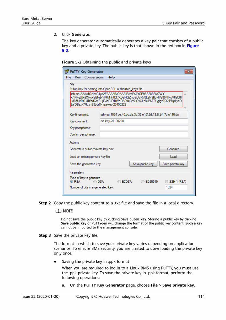
2. Click Generate.The key generator automatically generates a key pair that consists of a publickey and a private key. The public key is that shown in the red box in Figure5-2.
Figure 5-2 Obtaining the public and private keys
Step 2 Copy the public key content to a .txt file and save the file in a local directory.
Do not save the public key by clicking Save public key. Storing a public key by clickingSave public key of PuTTYgen will change the format of the public key content. Such a keycannot be imported to the management console.
Step 3 Save the private key file.
The format in which to save your private key varies depending on applicationscenarios: To ensure BMS security, you are limited to downloading the private keyonly once.
● Saving the private key in .ppk formatWhen you are required to log in to a Linux BMS using PuTTY, you must usethe .ppk private key. To save the private key in .ppk format, perform thefollowing operations:
a. On the PuTTY Key Generator page, choose File > Save private key.
Bare Metal ServerUser Guide 5 Key Pair and Password
Issue 22 (2020-01-20) Copyright © Huawei Technologies Co., Ltd. 114
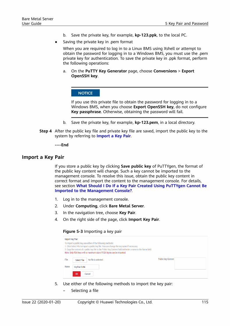
b. Save the private key, for example, kp-123.ppk, to the local PC.● Saving the private key in .pem format
When you are required to log in to a Linux BMS using Xshell or attempt toobtain the password for logging in to a Windows BMS, you must use the .pemprivate key for authentication. To save the private key in .ppk format, performthe following operations:
a. On the PuTTY Key Generator page, choose Conversions > ExportOpenSSH key.
NO TICE
If you use this private file to obtain the password for logging in to aWindows BMS, when you choose Export OpenSSH key, do not configureKey passphrase. Otherwise, obtaining the password will fail.
b. Save the private key, for example, kp-123.pem, in a local directory.
Step 4 After the public key file and private key file are saved, import the public key to thesystem by referring to Import a Key Pair.
----End
Import a Key Pair
If you store a public key by clicking Save public key of PuTTYgen, the format ofthe public key content will change. Such a key cannot be imported to themanagement console. To resolve this issue, obtain the public key content incorrect format and import the content to the management console. For details,see section What Should I Do If a Key Pair Created Using PuTTYgen Cannot BeImported to the Management Console?.
1. Log in to the management console.2. Under Computing, click Bare Metal Server.3. In the navigation tree, choose Key Pair.4. On the right side of the page, click Import Key Pair.
Figure 5-3 Importing a key pair
5. Use either of the following methods to import the key pair:– Selecting a file
Bare Metal ServerUser Guide 5 Key Pair and Password
Issue 22 (2020-01-20) Copyright © Huawei Technologies Co., Ltd. 115
i. On the Import Key Pair page of the management console, clickSelect File and select the local public key file, for example, the .txtfile saved in Step 2.
When importing a key pair, ensure that the public key is imported.Otherwise, importing the key pair will fail.
ii. Click OK.After the public key is imported, you can change its name.
– Copying the public key content
i. Copy the content of the public key in .txt file into the Public KeyContent text box.
ii. Click OK.
What Can I Do If My Private Key File Is Lost?You are advised to enable Data Encryption Workshop (DEW). Then, you canmanage key pairs, including binding, viewing, resetting, replacing, unbinding, anddeleting key pairs. For details, see section Managing Key Pairs.
Example:
● If a private key file is lost, you can reset the key pair of the BMS.● If a private key file is leaked, you can use a new key pair to replace the
original one of the BMS.
Delete a Key PairIf you no longer need a key pair, you can delete it. After a key pair is deleted, itcannot be restored. However, you can still use the private key saved locally to login to the BMS, and the deleted key pair is still displayed in the BMS details.
● If your key pair has been bound to a BMS and you do not unbind the key pair from theBMS before deleting the key pair, you cannot create a key pair of the same name. Whenyou enter this name when creating or importing a key pair, the console displays an errormessage indicating that the key pair already exists.
● If your key pair is not bound to any BMS or has been unbound from the BMS before it isdeleted, you can create a key pair of the same name.
1. Log in to the management console.2. Under Computing, click Bare Metal Server.3. In the navigation tree, choose Key Pair.4. Locate the row that contains the target key pair and click Delete in the
Operation column.
Bare Metal ServerUser Guide 5 Key Pair and Password
Issue 22 (2020-01-20) Copyright © Huawei Technologies Co., Ltd. 116
5.2 (Optional) Installing the One-Click Password ResetPlug-in
Scenarios
If the password of your BMS is lost or expires and your BMS has the passwordreset plug-in CloudResetPwdAgent installed, you can reset the password by a fewclicks.
This method is convenient and efficient. After you have created a BMS, you areadvised to log in to it and install the password reset plugins.
By default, the one-click password reset plug-in has been installed on the BMSs createdusing public images. To check whether the plug-in has been installed for the BMS, see stepStep 1 in "Install the Password Reset Plug-ins on a Linux BMS" or step Step 1 in "Install thePassword Reset Plug-ins on a Windows BMS".
Notes1. Do not use any other password reset plug-in.2. It is up to you to decide whether to install the CloudResetPwdAgent plugin.3. After installing the plug-in, do not uninstall it. Otherwise, the management
console may fail to reset the password.4. After you reinstall or change the BMS OS, the one-click password resetting
function will become invalid. If you still want to use this function, reinstall theCloudResetPwdAgent plug-in.
5. CloudResetPwdAgent can be automatically upgraded only if an EIP is boundto the BMS. You can also download the upgrade package and upgradeCloudResetPwdAgent manually.
6. The one-click password reset plugin CloudResetPwdAgent has been open-sourced in the Github platform according to GNU General Public License v2.0.
Prerequisites● The BMS must be in Running state.● A Windows BMS must have larger than 600 MB remaining space and data
can be written to its drive C.A Linux BMS must have larger than 600 MB remaining space and data can bewritten to its root directory.
● Ensure that DHCP is enabled in the VPC to which the BMS belongs.● The BMS network connectivity is normal.● Ensure that security group rules in the outbound direction meet the following
requirements:– Protocol: TCP– Port Range: 80
Bare Metal ServerUser Guide 5 Key Pair and Password
Issue 22 (2020-01-20) Copyright © Huawei Technologies Co., Ltd. 117
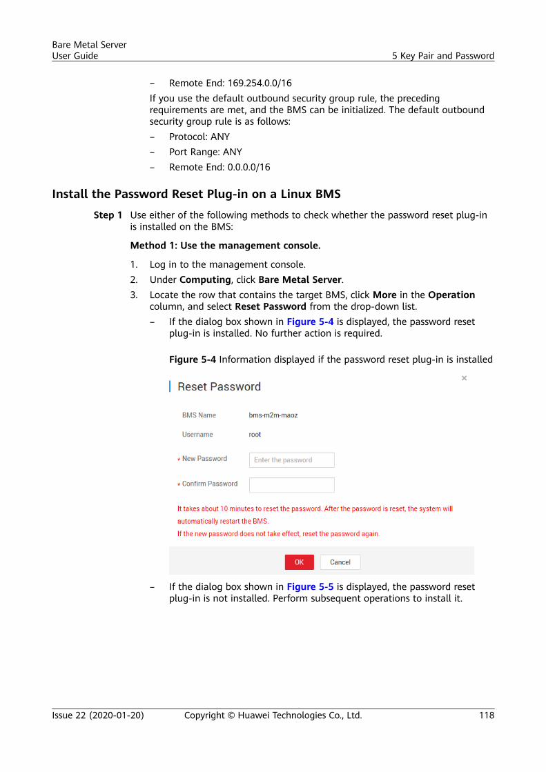
– Remote End: 169.254.0.0/16If you use the default outbound security group rule, the precedingrequirements are met, and the BMS can be initialized. The default outboundsecurity group rule is as follows:– Protocol: ANY– Port Range: ANY– Remote End: 0.0.0.0/16
Install the Password Reset Plug-in on a Linux BMS
Step 1 Use either of the following methods to check whether the password reset plug-inis installed on the BMS:
Method 1: Use the management console.
1. Log in to the management console.2. Under Computing, click Bare Metal Server.3. Locate the row that contains the target BMS, click More in the Operation
column, and select Reset Password from the drop-down list.– If the dialog box shown in Figure 5-4 is displayed, the password reset
plug-in is installed. No further action is required.
Figure 5-4 Information displayed if the password reset plug-in is installed
– If the dialog box shown in Figure 5-5 is displayed, the password resetplug-in is not installed. Perform subsequent operations to install it.
Bare Metal ServerUser Guide 5 Key Pair and Password
Issue 22 (2020-01-20) Copyright © Huawei Technologies Co., Ltd. 118
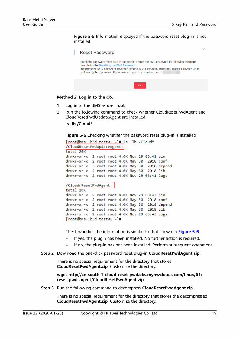
Figure 5-5 Information displayed if the password reset plug-in is notinstalled
Method 2: Log in to the OS.
1. Log in to the BMS as user root.2. Run the following command to check whether CloudResetPwdAgent and
CloudResetPwdUpdateAgent are installed:ls -lh /Cloud*
Figure 5-6 Checking whether the password reset plug-in is installed
Check whether the information is similar to that shown in Figure 5-6.– If yes, the plugin has been installed. No further action is required.– If no, the plug-in has not been installed. Perform subsequent operations.
Step 2 Download the one-click password reset plug-in CloudResetPwdAgent.zip.
There is no special requirement for the directory that storesCloudResetPwdAgent.zip. Customize the directory.
wget http://cn-south-1-cloud-reset-pwd.obs.myhwclouds.com/linux/64/reset_pwd_agent/CloudResetPwdAgent.zip
Step 3 Run the following command to decompress CloudResetPwdAgent.zip.
There is no special requirement for the directory that stores the decompressedCloudResetPwdAgent.zip. Customize the directory.
Bare Metal ServerUser Guide 5 Key Pair and Password
Issue 22 (2020-01-20) Copyright © Huawei Technologies Co., Ltd. 119
unzip -o -d Plug-in decompression directory CloudResetPwdAgent.zip
Example:
If the decompressed directory is /home/linux/test, run the following command:
unzip -o -d /home/linux/test CloudResetPwdAgent.zip
Step 4 Install password reset plugins CloudResetPwdAgent andCloudResetPwdUpdateAgent.
1. Run the following command to open the CloudResetPwdUpdateAgent.Linuxfile:cd /home/linux/test/CloudResetPwdAgent/CloudResetPwdAgent/CloudResetPwdUpdateAgent.Linux
2. Run the following command to add the execute permission for the setup.shfile:chmod +x setup.sh
3. Run the following command to install the plugins:sudo sh setup.sh
4. Run the following commands to check whether the installation is successful:service cloudResetPwdUpdateAgent statusIf the status of CoudResetPwdUpdateAgent is running, plugin installation issuccessful. Otherwise, the installation fails.
You can also check whether the password reset plug-in is installed successfully basedon Step 1.If the installation fails, check whether the installation environment meetsrequirements and install the plugin again.
----End
Install the Password Reset Plug-in on a Windows BMS
Step 1 Check whether CloudResetPwdAgent and CloudResetPwdUpdateAgent have beeninstalled on the BMS. To check this, perform the following operations:
Start the Task Manager and check whether cloudResetPwdAgent andCloudResetPwdUpdateAgent are displayed on the Services page.
Bare Metal ServerUser Guide 5 Key Pair and Password
Issue 22 (2020-01-20) Copyright © Huawei Technologies Co., Ltd. 120
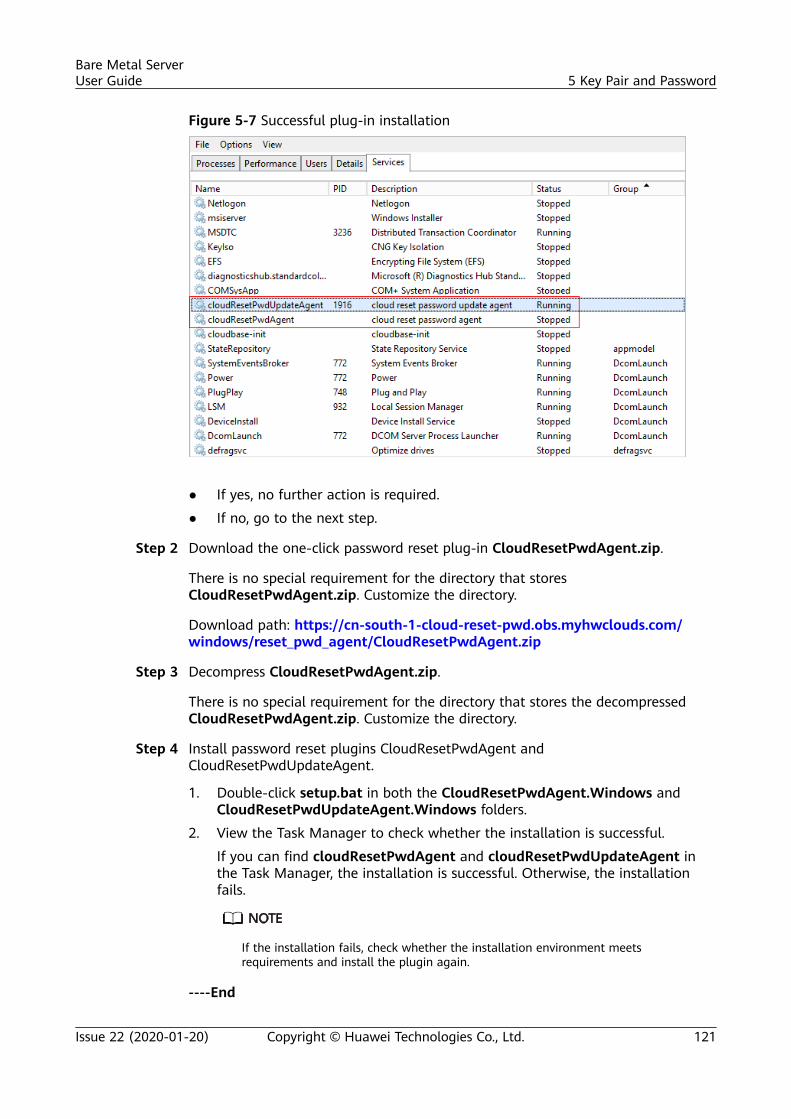
Figure 5-7 Successful plug-in installation
● If yes, no further action is required.
● If no, go to the next step.
Step 2 Download the one-click password reset plug-in CloudResetPwdAgent.zip.
There is no special requirement for the directory that storesCloudResetPwdAgent.zip. Customize the directory.
Download path: https://cn-south-1-cloud-reset-pwd.obs.myhwclouds.com/windows/reset_pwd_agent/CloudResetPwdAgent.zip
Step 3 Decompress CloudResetPwdAgent.zip.
There is no special requirement for the directory that stores the decompressedCloudResetPwdAgent.zip. Customize the directory.
Step 4 Install password reset plugins CloudResetPwdAgent andCloudResetPwdUpdateAgent.
1. Double-click setup.bat in both the CloudResetPwdAgent.Windows andCloudResetPwdUpdateAgent.Windows folders.
2. View the Task Manager to check whether the installation is successful.
If you can find cloudResetPwdAgent and cloudResetPwdUpdateAgent inthe Task Manager, the installation is successful. Otherwise, the installationfails.
If the installation fails, check whether the installation environment meetsrequirements and install the plugin again.
----End
Bare Metal ServerUser Guide 5 Key Pair and Password
Issue 22 (2020-01-20) Copyright © Huawei Technologies Co., Ltd. 121
Uninstall the Password Reset Plug-inIf you do not need the password reset function any longer, perform the followingoperations to uninstall the plug-in:
● Linux BMSsLog in to the BMS as user root and run the following commands:
a. sudo bash /CloudrResetPwdAgent/bin/cloudResetPwdAgent.scriptremove
b. sudo bash /CloudResetPwdUpdateAgent/bin/cloudResetPwdUpdateAgent.script remove
c. sudo rm -rf /CloudrResetPwdAgentd. sudo rm -rf /CloudResetPwdUpdateAgent
● Windows BMSs
a. Log in to the BMS and go to the C:\CloudResetPwdUpdateAgent\bindirectory.
b. Double-click UninstallApp-NT.bat.c. Delete C:\CloudResetPwdUpdateAgent.d. Go to the C:\CloudResetPwdAgent\bin directory.e. Double-click UninstallApp-NT.bat.f. Delete C:\CloudResetPwdAgent.
5.3 Obtaining the Password of a Windows BMS
ScenariosPassword authentication mode is required to log in to a Windows BMS. Therefore,you must use the key file used when you created the BMS to obtain theadministrator password generated when the BMS was initially installed. Theadministrator user is Administrator or the user configured using Cloudbase-Init.This password is randomly generated, offering high security.
PrerequisitesYou have obtained the private key file used during BMS creation.
Procedure1. Log in to the management console.2. Under Computing, click Bare Metal Server.3. Locate the row that contains the Windows BMS, click More in the Operation
column, and select Obtain Password.
Bare Metal ServerUser Guide 5 Key Pair and Password
Issue 22 (2020-01-20) Copyright © Huawei Technologies Co., Ltd. 122
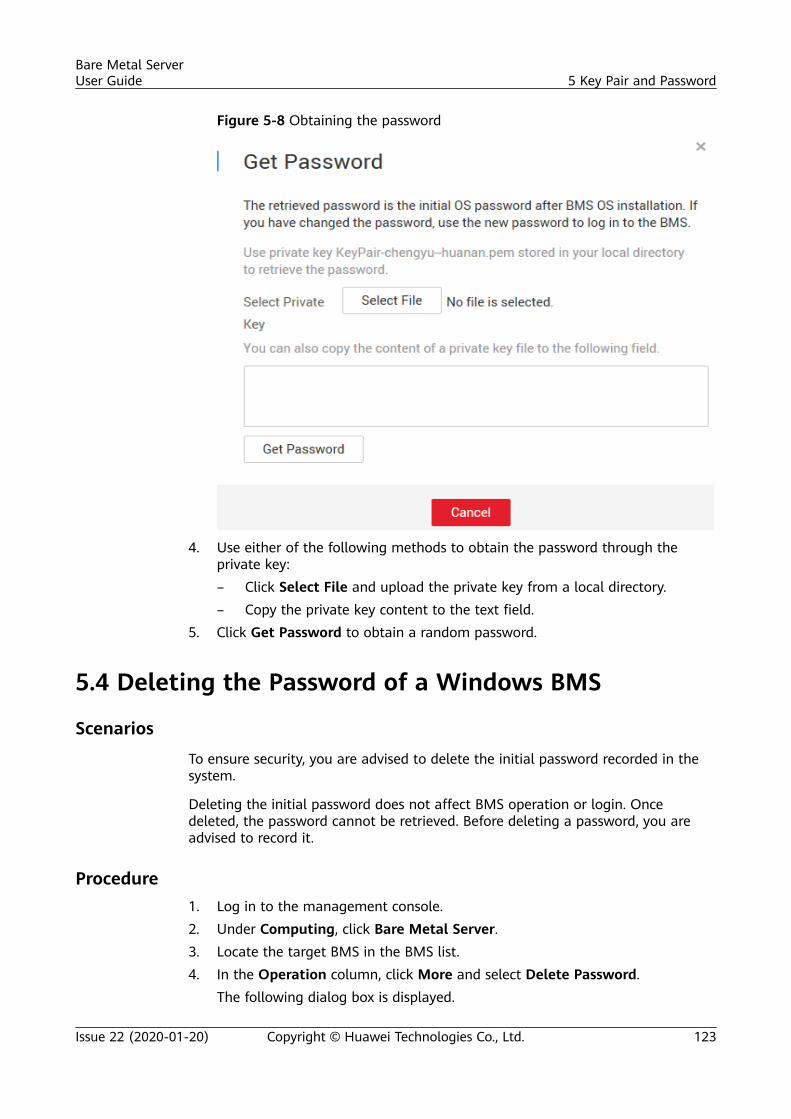
Figure 5-8 Obtaining the password
4. Use either of the following methods to obtain the password through theprivate key:– Click Select File and upload the private key from a local directory.– Copy the private key content to the text field.
5. Click Get Password to obtain a random password.
5.4 Deleting the Password of a Windows BMS
Scenarios
To ensure security, you are advised to delete the initial password recorded in thesystem.
Deleting the initial password does not affect BMS operation or login. Oncedeleted, the password cannot be retrieved. Before deleting a password, you areadvised to record it.
Procedure1. Log in to the management console.2. Under Computing, click Bare Metal Server.3. Locate the target BMS in the BMS list.4. In the Operation column, click More and select Delete Password.
The following dialog box is displayed.
Bare Metal ServerUser Guide 5 Key Pair and Password
Issue 22 (2020-01-20) Copyright © Huawei Technologies Co., Ltd. 123
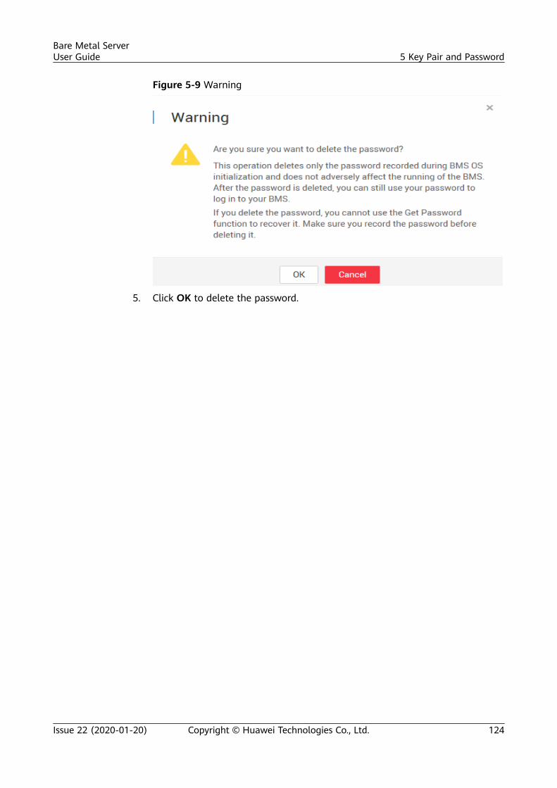
Figure 5-9 Warning
5. Click OK to delete the password.
Bare Metal ServerUser Guide 5 Key Pair and Password
Issue 22 (2020-01-20) Copyright © Huawei Technologies Co., Ltd. 124
6 Network
6.1 EIP
6.1.1 Overview
EIPThe Elastic IP (EIP) service provides independent public IP addresses andbandwidth for Internet access. Different from traditional static IP addresses, EIPscan be dynamically bound to or unbound from resources such as BMSs, ECSs, andNAT gateways. If a server becomes faulty, the EIP can be quickly unbound from itand bound to another healthy server to recover services.
Bare Metal ServerUser Guide 6 Network
Issue 22 (2020-01-20) Copyright © Huawei Technologies Co., Ltd. 125
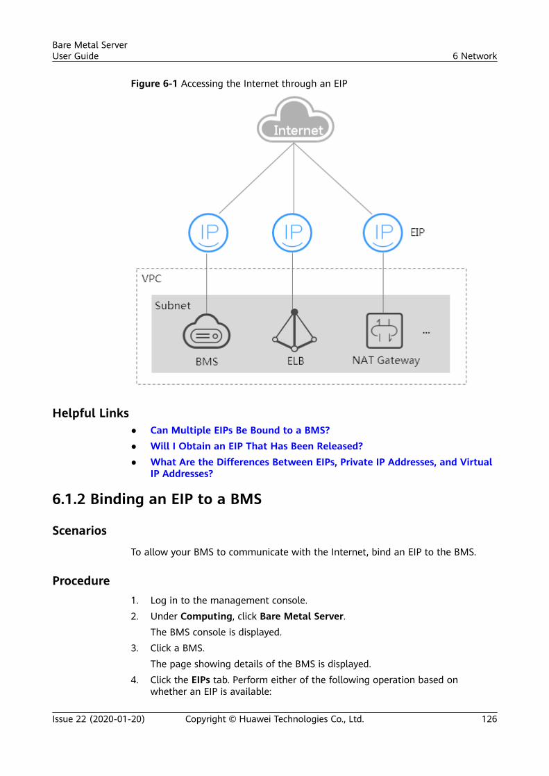
Figure 6-1 Accessing the Internet through an EIP
Helpful Links● Can Multiple EIPs Be Bound to a BMS?● Will I Obtain an EIP That Has Been Released?● What Are the Differences Between EIPs, Private IP Addresses, and Virtual
IP Addresses?
6.1.2 Binding an EIP to a BMS
Scenarios
To allow your BMS to communicate with the Internet, bind an EIP to the BMS.
Procedure1. Log in to the management console.2. Under Computing, click Bare Metal Server.
The BMS console is displayed.3. Click a BMS.
The page showing details of the BMS is displayed.4. Click the EIPs tab. Perform either of the following operation based on
whether an EIP is available:
Bare Metal ServerUser Guide 6 Network
Issue 22 (2020-01-20) Copyright © Huawei Technologies Co., Ltd. 126
– If an EIP is available, perform steps 8 and 9.– If no EIP is available, perform steps 5 to 9.
5. Click View EIP.The EIP console is displayed.
6. Click Buy EIP. On the displayed page, enter the bandwidth name, bandwidthsize, and quantity, and click Buy NowThe page for you to confirm EIP configuration is displayed.
7. Click Submit.The page showing details of the BMS is displayed.
8. Click Bind EIP.The Bind EIP page is displayed.
9. Select the target EIP and click OK.
Only one EIP can be bound to a NIC.
6.1.3 Unbinding an EIP from a BMS
ScenariosThis section describes how to unbind an EIP from a BMS.
Procedure1. Log in to the management console.2. Under Computing, click Bare Metal Server.
The BMS console is displayed.3. Click a BMS.
The page showing details of the BMS is displayed.4. Click the EIPs tab. On the displayed page, locate the target EIP and click
Unbind. In the displayed dialog box, click Yes.
6.1.4 Changing an EIP Bandwidth
ScenariosIf an EIP has been bound to a BMS, the BMS can access the Internet usingspecified bandwidth. This section describes how to modify the BMS bandwidth.
Procedure1. Log in to the management console.2. Under Computing, click Bare Metal Server.3. In the BMS list, click the name of the target BMS.
The page showing details of the BMS is displayed.4. Click the EIPs tab. Expand the information of the EIP to be modified and click
the ID hyperlink.
Bare Metal ServerUser Guide 6 Network
Issue 22 (2020-01-20) Copyright © Huawei Technologies Co., Ltd. 127
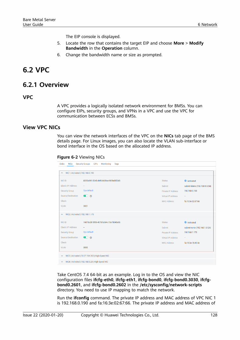
The EIP console is displayed.5. Locate the row that contains the target EIP and choose More > Modify
Bandwidth in the Operation column.6. Change the bandwidth name or size as prompted.
6.2 VPC
6.2.1 Overview
VPCA VPC provides a logically isolated network environment for BMSs. You canconfigure EIPs, security groups, and VPNs in a VPC and use the VPC forcommunication between ECSs and BMSs.
View VPC NICsYou can view the network interfaces of the VPC on the NICs tab page of the BMSdetails page. For Linux images, you can also locate the VLAN sub-interface orbond interface in the OS based on the allocated IP address.
Figure 6-2 Viewing NICs
Take CentOS 7.4 64-bit as an example. Log in to the OS and view the NICconfiguration files ifcfg-eth0, ifcfg-eth1, ifcfg-bond0, ifcfg-bond0.3030, ifcfg-bond0.2601, and ifcfg-bond0.2602 in the /etc/sysconfig/network-scriptsdirectory. You need to use IP mapping to match the network.
Run the ifconfig command. The private IP address and MAC address of VPC NIC 1is 192.168.0.190 and fa:16:3e:02:67:66. The private IP address and MAC address of
Bare Metal ServerUser Guide 6 Network
Issue 22 (2020-01-20) Copyright © Huawei Technologies Co., Ltd. 128
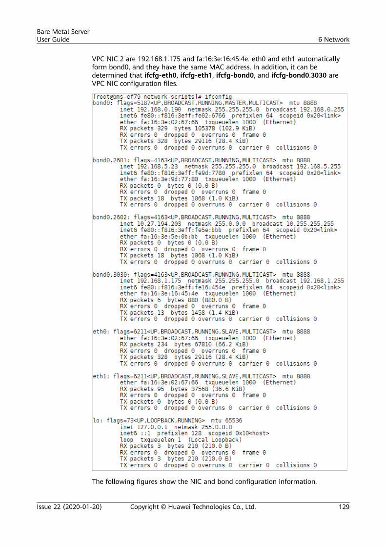
VPC NIC 2 are 192.168.1.175 and fa:16:3e:16:45:4e. eth0 and eth1 automaticallyform bond0, and they have the same MAC address. In addition, it can bedetermined that ifcfg-eth0, ifcfg-eth1, ifcfg-bond0, and ifcfg-bond0.3030 areVPC NIC configuration files.
The following figures show the NIC and bond configuration information.
Bare Metal ServerUser Guide 6 Network
Issue 22 (2020-01-20) Copyright © Huawei Technologies Co., Ltd. 129
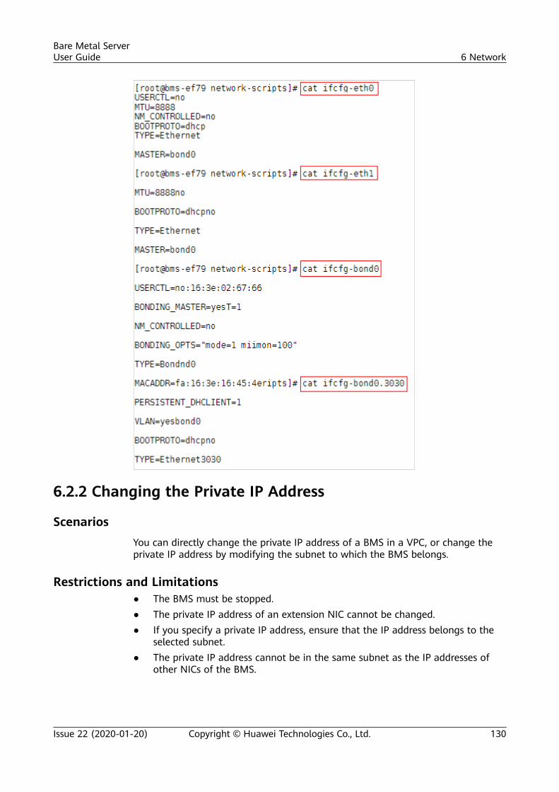
6.2.2 Changing the Private IP Address
ScenariosYou can directly change the private IP address of a BMS in a VPC, or change theprivate IP address by modifying the subnet to which the BMS belongs.
Restrictions and Limitations● The BMS must be stopped.● The private IP address of an extension NIC cannot be changed.● If you specify a private IP address, ensure that the IP address belongs to the
selected subnet.● The private IP address cannot be in the same subnet as the IP addresses of
other NICs of the BMS.
Bare Metal ServerUser Guide 6 Network
Issue 22 (2020-01-20) Copyright © Huawei Technologies Co., Ltd. 130
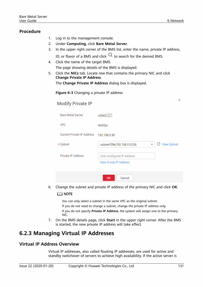
Procedure1. Log in to the management console.2. Under Computing, click Bare Metal Server.3. In the upper right corner of the BMS list, enter the name, private IP address,
ID, or flavor of a BMS and click to search for the desired BMS.4. Click the name of the target BMS.
The page showing details of the BMS is displayed.5. Click the NICs tab. Locate row that contains the primary NIC and click
Change Private IP Address.The Change Private IP Address dialog box is displayed.
Figure 6-3 Changing a private IP address
6. Change the subnet and private IP address of the primary NIC and click OK.
You can only select a subnet in the same VPC as the original subnet.If you do not need to change a subnet, change the private IP address only.If you do not specify Private IP Address, the system will assign one to the primaryNIC.
7. On the BMS details page, click Start in the upper right corner. After the BMSis started, the new private IP address will take effect.
6.2.3 Managing Virtual IP Addresses
Virtual IP Address OverviewVirtual IP addresses, also called floating IP addresses, are used for active andstandby switchover of servers to achieve high availability. If the active server is
Bare Metal ServerUser Guide 6 Network
Issue 22 (2020-01-20) Copyright © Huawei Technologies Co., Ltd. 131
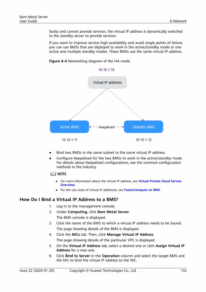
faulty and cannot provide services, the virtual IP address is dynamically switchedto the standby server to provide services.
If you want to improve service high availability and avoid single points of failure,you can use BMSs that are deployed to work in the active/standby mode or oneactive and multiple standby modes. These BMSs use the same virtual IP address.
Figure 6-4 Networking diagram of the HA mode
● Bind two BMSs in the same subnet to the same virtual IP address.● Configure Keepalived for the two BMSs to work in the active/standby mode.
For details about Keepalived configurations, see the common configurationmethods in the industry.
● For more information about the virtual IP address, see Virtual Private Cloud ServiceOverview.
● For the use cases of virtual IP addresses, see FusionCompute on BMS.
How Do I Bind a Virtual IP Address to a BMS?1. Log in to the management console.2. Under Computing, click Bare Metal Server.
The BMS console is displayed.3. Click the name of the BMS to which a virtual IP address needs to be bound.
The page showing details of the BMS is displayed.4. Click the NICs tab. Then, click Manage Virtual IP Address.
The page showing details of the particular VPC is displayed.5. On the Virtual IP Address tab, select a desired one or click Assign Virtual IP
Address for a new one.6. Click Bind to Server in the Operation column and select the target BMS and
the NIC to bind the virtual IP address to the NIC.
Bare Metal ServerUser Guide 6 Network
Issue 22 (2020-01-20) Copyright © Huawei Technologies Co., Ltd. 132
6.2.4 Setting the Source/Destination Check for a NIC
Procedure1. Log in to the management console.2. Under Computing, click Bare Metal Server.
The BMS console is displayed.3. Click the name of the target BMS.
The page showing details of the BMS is displayed.4. Select the NIC tab. On the displayed page, click the icon before the NIC to be
configured.5. Enable or disable the source/destination check function.
By default, the source/destination check function is enabled. When thisfunction is enabled, the system checks whether source IP addresses containedin the packets sent by BMSs are correct. If the IP addresses are incorrect, thesystem does not allow the BMSs to send the packets. This mechanismprevents packet spoofing, thereby improving system security. If the BMSfunctions as a NAT server, router, or firewall, you must disable the source/destination check for the BMS.
6.2.5 Enabling IPv4/IPv6 Dual Stack
Scenarios
IPv4/IPv6 dual stack allows your BMSs to use both the IPv4 and IPv6 addresses forprivate and public network communication. This section describes how to enableIPv4/IPv6 dual stack.
Notes● Currently, IPv4/IPv6 dual stack is in open beta test only in the CN North-
Beijing4 region.● Currently, you can only enable IPv6 when creating a BMS, rather than when
adding a NIC. After IPv6 is enabled, it cannot be disabled.● After IPv4/IPv6 dual stack is enabled, a BMS has an IPv4 and an IPv6 address,
and cannot use the IPv6 address alone.
Procedure1. Enable the IPv6 function of the VPC subnet.
a. Log in to the management console. Under Network, click Virtual PrivateCloud. On the displayed VPC console, click the name of the target VPC.
b. Click the Subnets tab. Locate the row that contains the target subnet andclick Enable IPv6 in the Operation column.
The IPv6 function cannot be disabled after it is enabled.
2. Create a BMS and enable IPv4/IPv6 dual stack.
Bare Metal ServerUser Guide 6 Network
Issue 22 (2020-01-20) Copyright © Huawei Technologies Co., Ltd. 133
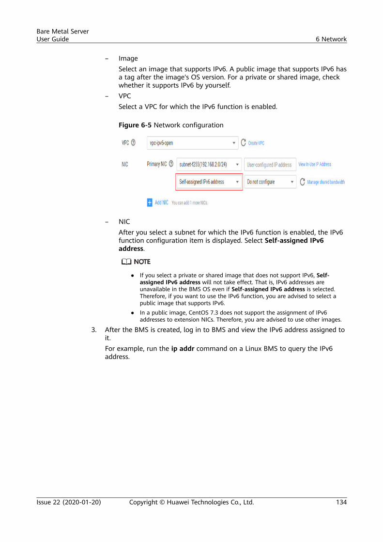
– ImageSelect an image that supports IPv6. A public image that supports IPv6 hasa tag after the image's OS version. For a private or shared image, checkwhether it supports IPv6 by yourself.
– VPCSelect a VPC for which the IPv6 function is enabled.
Figure 6-5 Network configuration
– NICAfter you select a subnet for which the IPv6 function is enabled, the IPv6function configuration item is displayed. Select Self-assigned IPv6address.
● If you select a private or shared image that does not support IPv6, Self-assigned IPv6 address will not take effect. That is, IPv6 addresses areunavailable in the BMS OS even if Self-assigned IPv6 address is selected.Therefore, if you want to use the IPv6 function, you are advised to select apublic image that supports IPv6.
● In a public image, CentOS 7.3 does not support the assignment of IPv6addresses to extension NICs. Therefore, you are advised to use other images.
3. After the BMS is created, log in to BMS and view the IPv6 address assigned toit.For example, run the ip addr command on a Linux BMS to query the IPv6address.
Bare Metal ServerUser Guide 6 Network
Issue 22 (2020-01-20) Copyright © Huawei Technologies Co., Ltd. 134
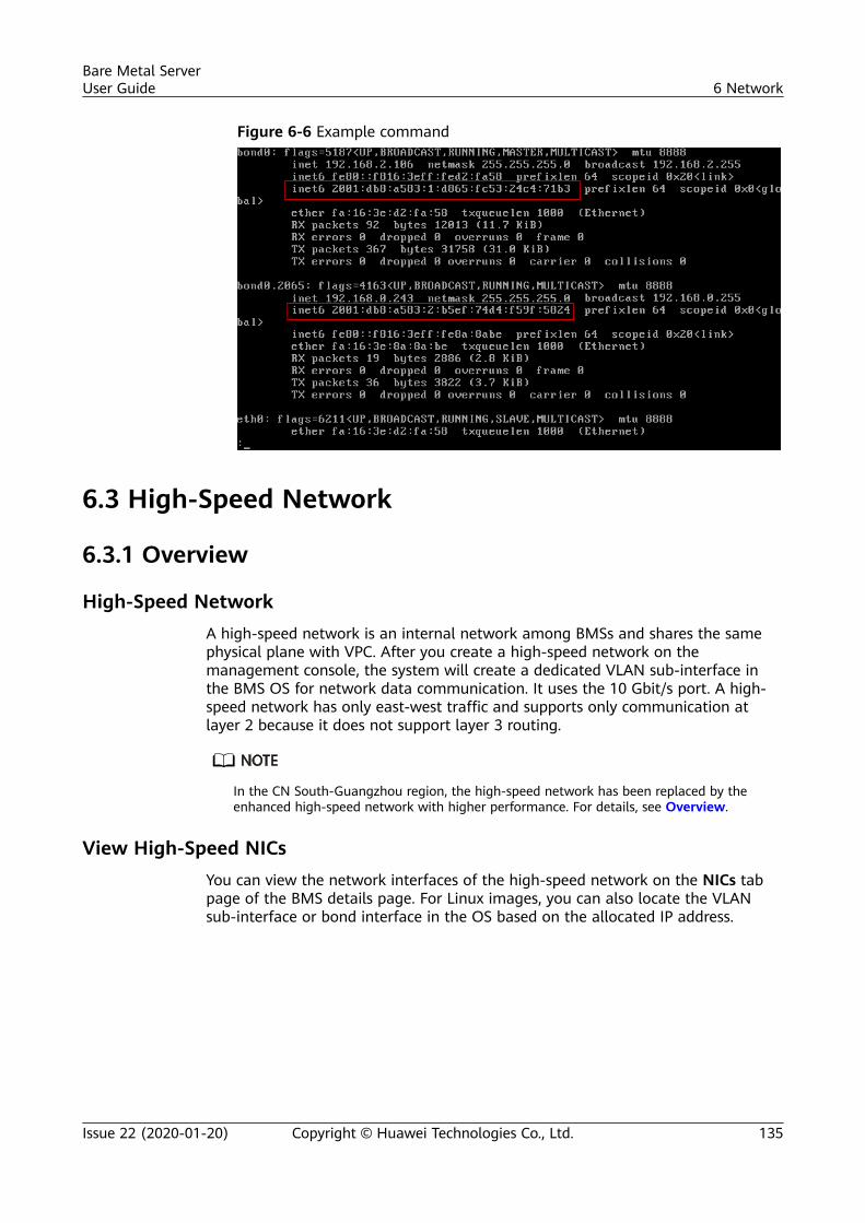
Figure 6-6 Example command
6.3 High-Speed Network
6.3.1 Overview
High-Speed NetworkA high-speed network is an internal network among BMSs and shares the samephysical plane with VPC. After you create a high-speed network on themanagement console, the system will create a dedicated VLAN sub-interface inthe BMS OS for network data communication. It uses the 10 Gbit/s port. A high-speed network has only east-west traffic and supports only communication atlayer 2 because it does not support layer 3 routing.
In the CN South-Guangzhou region, the high-speed network has been replaced by theenhanced high-speed network with higher performance. For details, see Overview.
View High-Speed NICsYou can view the network interfaces of the high-speed network on the NICs tabpage of the BMS details page. For Linux images, you can also locate the VLANsub-interface or bond interface in the OS based on the allocated IP address.
Bare Metal ServerUser Guide 6 Network
Issue 22 (2020-01-20) Copyright © Huawei Technologies Co., Ltd. 135
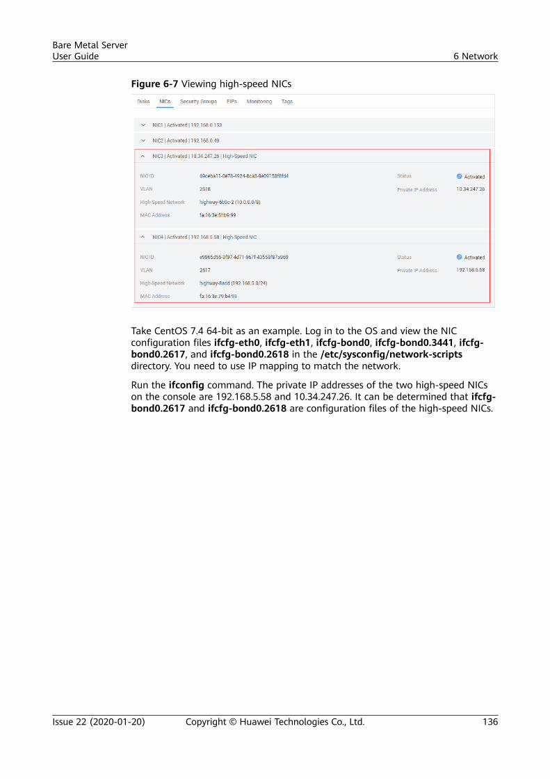
Figure 6-7 Viewing high-speed NICs
Take CentOS 7.4 64-bit as an example. Log in to the OS and view the NICconfiguration files ifcfg-eth0, ifcfg-eth1, ifcfg-bond0, ifcfg-bond0.3441, ifcfg-bond0.2617, and ifcfg-bond0.2618 in the /etc/sysconfig/network-scriptsdirectory. You need to use IP mapping to match the network.
Run the ifconfig command. The private IP addresses of the two high-speed NICson the console are 192.168.5.58 and 10.34.247.26. It can be determined that ifcfg-bond0.2617 and ifcfg-bond0.2618 are configuration files of the high-speed NICs.
Bare Metal ServerUser Guide 6 Network
Issue 22 (2020-01-20) Copyright © Huawei Technologies Co., Ltd. 136
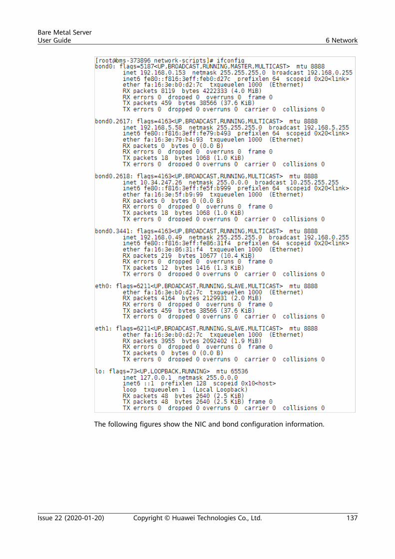
The following figures show the NIC and bond configuration information.
Bare Metal ServerUser Guide 6 Network
Issue 22 (2020-01-20) Copyright © Huawei Technologies Co., Ltd. 137
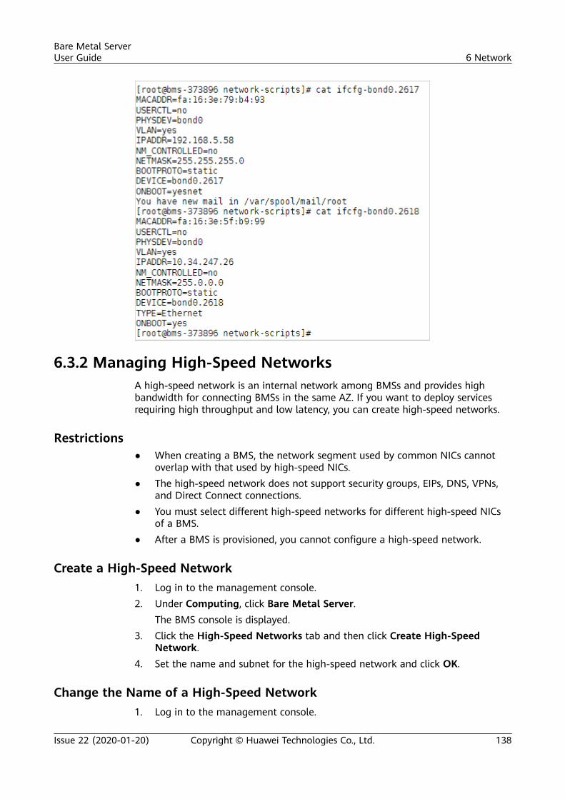
6.3.2 Managing High-Speed NetworksA high-speed network is an internal network among BMSs and provides highbandwidth for connecting BMSs in the same AZ. If you want to deploy servicesrequiring high throughput and low latency, you can create high-speed networks.
Restrictions● When creating a BMS, the network segment used by common NICs cannot
overlap with that used by high-speed NICs.● The high-speed network does not support security groups, EIPs, DNS, VPNs,
and Direct Connect connections.● You must select different high-speed networks for different high-speed NICs
of a BMS.● After a BMS is provisioned, you cannot configure a high-speed network.
Create a High-Speed Network1. Log in to the management console.2. Under Computing, click Bare Metal Server.
The BMS console is displayed.3. Click the High-Speed Networks tab and then click Create High-Speed
Network.4. Set the name and subnet for the high-speed network and click OK.
Change the Name of a High-Speed Network1. Log in to the management console.
Bare Metal ServerUser Guide 6 Network
Issue 22 (2020-01-20) Copyright © Huawei Technologies Co., Ltd. 138
2. Under Computing, click Bare Metal Server.The BMS console is displayed.
3. Click the High-Speed Networks tab. Locate the target high-speed networkand click Modify in the Operation column.
4. Change the high-speed network name and click OK.
Manage Private IP Addresses1. Log in to the management console.2. Under Computing, click Bare Metal Server.
The BMS console is displayed.3. Click the High-Speed Networks tab. Locate the target high-speed network,
click More in the Operation column, and select Manage Private IP Addressfrom the drop-down list.– To reserve a private IP address in the high-speed network for binding the
IP address to a BMS during BMS creation or for other purposes, performsteps 4 to 5.
– To delete a private IP address, perform step 6.4. Click Assign Private IP Address.
– If you select Automatic Assignment, the system automatically assigns aprivate IP address.
– If you select Manual Assignment, you can specify a specific IP address inthe high-speed network segment as the private IP address.
5. Click OK.6. Locate the row that contains the target private IP address, and click Delete in
the Operation column. In the displayed dialog box, click OK to delete the IPaddress.
6.4 Enhanced High-Speed Network
6.4.1 Overview
Enhanced High-Speed Network
The enhanced high-speed network is available only in the CN South-Guangzhou region.
Bare Metal ServerUser Guide 6 Network
Issue 22 (2020-01-20) Copyright © Huawei Technologies Co., Ltd. 139
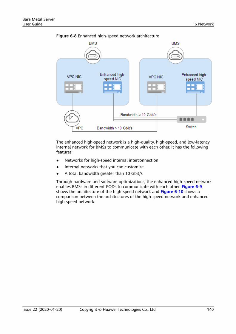
Figure 6-8 Enhanced high-speed network architecture
The enhanced high-speed network is a high-quality, high-speed, and low-latencyinternal network for BMSs to communicate with each other. It has the followingfeatures:
● Networks for high-speed internal interconnection● Internal networks that you can customize● A total bandwidth greater than 10 Gbit/s
Through hardware and software optimizations, the enhanced high-speed networkenables BMSs in different PODs to communicate with each other. Figure 6-9shows the architecture of the high-speed network and Figure 6-10 shows acomparison between the architectures of the high-speed network and enhancedhigh-speed network.
Bare Metal ServerUser Guide 6 Network
Issue 22 (2020-01-20) Copyright © Huawei Technologies Co., Ltd. 140
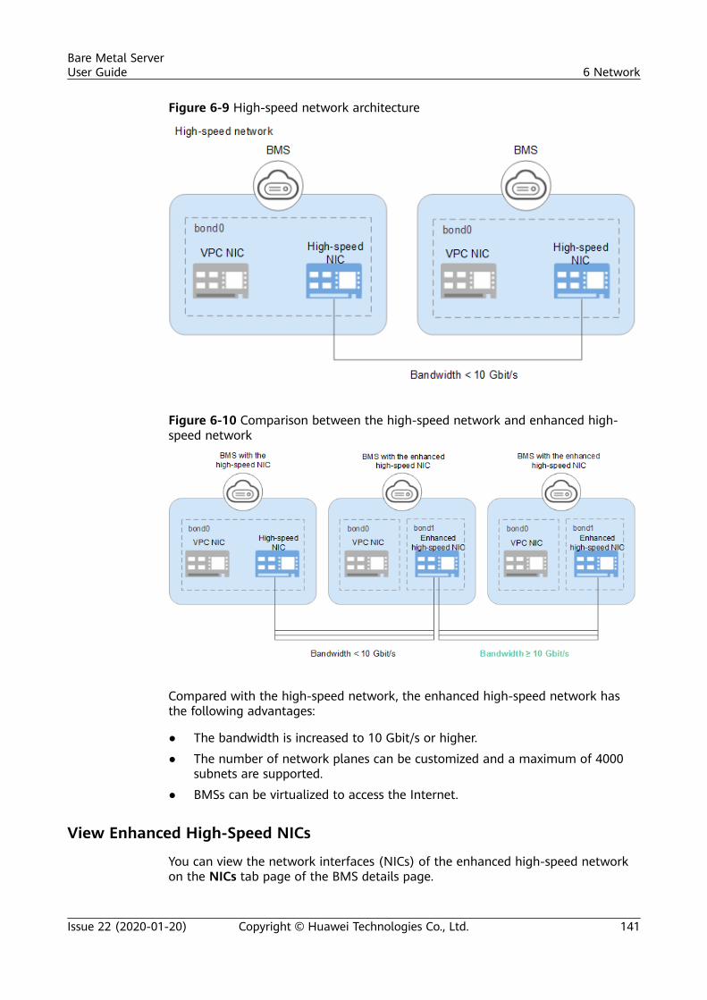
Figure 6-9 High-speed network architecture
Figure 6-10 Comparison between the high-speed network and enhanced high-speed network
Compared with the high-speed network, the enhanced high-speed network hasthe following advantages:
● The bandwidth is increased to 10 Gbit/s or higher.
● The number of network planes can be customized and a maximum of 4000subnets are supported.
● BMSs can be virtualized to access the Internet.
View Enhanced High-Speed NICs
You can view the network interfaces (NICs) of the enhanced high-speed networkon the NICs tab page of the BMS details page.
Bare Metal ServerUser Guide 6 Network
Issue 22 (2020-01-20) Copyright © Huawei Technologies Co., Ltd. 141
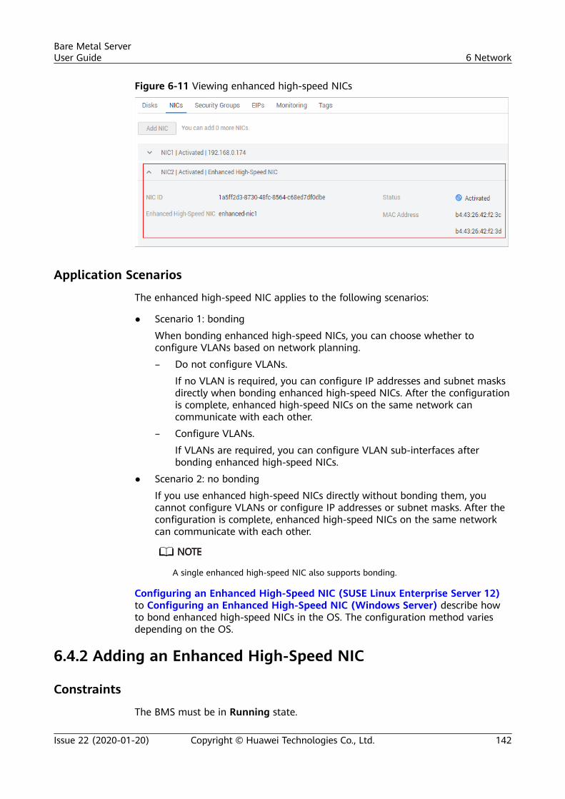
Figure 6-11 Viewing enhanced high-speed NICs
Application Scenarios
The enhanced high-speed NIC applies to the following scenarios:
● Scenario 1: bonding
When bonding enhanced high-speed NICs, you can choose whether toconfigure VLANs based on network planning.
– Do not configure VLANs.
If no VLAN is required, you can configure IP addresses and subnet masksdirectly when bonding enhanced high-speed NICs. After the configurationis complete, enhanced high-speed NICs on the same network cancommunicate with each other.
– Configure VLANs.
If VLANs are required, you can configure VLAN sub-interfaces afterbonding enhanced high-speed NICs.
● Scenario 2: no bonding
If you use enhanced high-speed NICs directly without bonding them, youcannot configure VLANs or configure IP addresses or subnet masks. After theconfiguration is complete, enhanced high-speed NICs on the same networkcan communicate with each other.
A single enhanced high-speed NIC also supports bonding.
Configuring an Enhanced High-Speed NIC (SUSE Linux Enterprise Server 12)to Configuring an Enhanced High-Speed NIC (Windows Server) describe howto bond enhanced high-speed NICs in the OS. The configuration method variesdepending on the OS.
6.4.2 Adding an Enhanced High-Speed NIC
Constraints
The BMS must be in Running state.
Bare Metal ServerUser Guide 6 Network
Issue 22 (2020-01-20) Copyright © Huawei Technologies Co., Ltd. 142
Add an Enhanced High-Speed NIC
To enable your BMS to communicate with resources in other PODs, add anenhanced high-speed NIC to the BMS.
1. Log in to the management console.
2. Under Computing, click Bare Metal Server.
The BMS console is displayed.
3. Click the name of the target BMS.
The page showing details of the BMS is displayed.
4. Click the NICs tab. Then, click Add Enhanced High-Speed NIC.
5. Select the bandwidth.
6. Click OK.
Follow-up Operations
The BMS cannot identify the newly added enhanced high-speed NIC. You mustmanually activate the NIC by following the instructions in sections Configuring anEnhanced High-Speed NIC (SUSE Linux Enterprise Server 12) to Configuringan Enhanced High-Speed NIC (Windows Server).
6.4.3 Deleting an Enhanced High-Speed NIC
Constraints
The BMS must be in Running or Stopped state.
Delete an Enhanced High-Speed NIC1. Log in to the management console.
2. Under Computing, click Bare Metal Server.
The BMS console is displayed.
3. Click the name of the target BMS.
The page showing details of the BMS is displayed.
4. Click the NICs tab, locate the target enhanced high-speed NIC, click toexpand its details, and make a note of the MAC address.
After deleting a NIC on the console, you need to log in to the BMS OS and performrelated operations to delete the device (the MAC address recorded will be used).
5. Click Delete.
6. Click Yes.
Bare Metal ServerUser Guide 6 Network
Issue 22 (2020-01-20) Copyright © Huawei Technologies Co., Ltd. 143
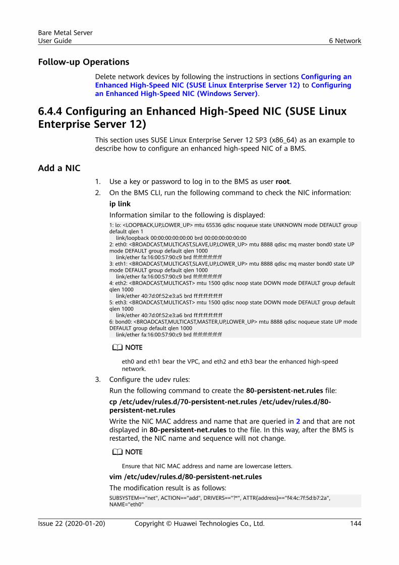
Follow-up OperationsDelete network devices by following the instructions in sections Configuring anEnhanced High-Speed NIC (SUSE Linux Enterprise Server 12) to Configuringan Enhanced High-Speed NIC (Windows Server).
6.4.4 Configuring an Enhanced High-Speed NIC (SUSE LinuxEnterprise Server 12)
This section uses SUSE Linux Enterprise Server 12 SP3 (x86_64) as an example todescribe how to configure an enhanced high-speed NIC of a BMS.
Add a NIC1. Use a key or password to log in to the BMS as user root.2. On the BMS CLI, run the following command to check the NIC information:
ip linkInformation similar to the following is displayed:1: lo: <LOOPBACK,UP,LOWER_UP> mtu 65536 qdisc noqueue state UNKNOWN mode DEFAULT group default qlen 1 link/loopback 00:00:00:00:00:00 brd 00:00:00:00:00:002: eth0: <BROADCAST,MULTICAST,SLAVE,UP,LOWER_UP> mtu 8888 qdisc mq master bond0 state UP mode DEFAULT group default qlen 1000 link/ether fa:16:00:57:90:c9 brd ff:ff:ff:ff:ff:ff3: eth1: <BROADCAST,MULTICAST,SLAVE,UP,LOWER_UP> mtu 8888 qdisc mq master bond0 state UP mode DEFAULT group default qlen 1000 link/ether fa:16:00:57:90:c9 brd ff:ff:ff:ff:ff:ff4: eth2: <BROADCAST,MULTICAST> mtu 1500 qdisc noop state DOWN mode DEFAULT group default qlen 1000 link/ether 40:7d:0f:52:e3:a5 brd ff:ff:ff:ff:ff:ff5: eth3: <BROADCAST,MULTICAST> mtu 1500 qdisc noop state DOWN mode DEFAULT group default qlen 1000 link/ether 40:7d:0f:52:e3:a6 brd ff:ff:ff:ff:ff:ff6: bond0: <BROADCAST,MULTICAST,MASTER,UP,LOWER_UP> mtu 8888 qdisc noqueue state UP mode DEFAULT group default qlen 1000 link/ether fa:16:00:57:90:c9 brd ff:ff:ff:ff:ff:ff
eth0 and eth1 bear the VPC, and eth2 and eth3 bear the enhanced high-speednetwork.
3. Configure the udev rules:Run the following command to create the 80-persistent-net.rules file:cp /etc/udev/rules.d/70-persistent-net.rules /etc/udev/rules.d/80-persistent-net.rulesWrite the NIC MAC address and name that are queried in 2 and that are notdisplayed in 80-persistent-net.rules to the file. In this way, after the BMS isrestarted, the NIC name and sequence will not change.
Ensure that NIC MAC address and name are lowercase letters.
vim /etc/udev/rules.d/80-persistent-net.rulesThe modification result is as follows:SUBSYSTEM=="net", ACTION=="add", DRIVERS=="?*", ATTR{address}=="f4:4c:7f:5d:b7:2a", NAME="eth0"
Bare Metal ServerUser Guide 6 Network
Issue 22 (2020-01-20) Copyright © Huawei Technologies Co., Ltd. 144
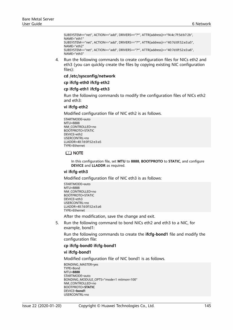
SUBSYSTEM=="net", ACTION=="add", DRIVERS=="?*", ATTR{address}=="f4:4c:7f:5d:b7:2b", NAME="eth1"SUBSYSTEM=="net", ACTION=="add", DRIVERS=="?*", ATTR{address}=="40:7d:0f:52:e3:a5", NAME="eth2"SUBSYSTEM=="net", ACTION=="add", DRIVERS=="?*", ATTR{address}=="40:7d:0f:52:e3:a6", NAME="eth3"
4. Run the following commands to create configuration files for NICs eth2 andeth3 (you can quickly create the files by copying existing NIC configurationfiles):cd /etc/sysconfig/networkcp ifcfg-eth0 ifcfg-eth2cp ifcfg-eth1 ifcfg-eth3Run the following commands to modify the configuration files of NICs eth2and eth3:vi ifcfg-eth2Modified configuration file of NIC eth2 is as follows.STARTMODE=autoMTU=8888NM_CONTROLLED=noBOOTPROTO=STATICDEVICE=eth2USERCONTRL=noLLADDR=40:7d:0f:52:e3:a5TYPE=Ethernet
In this configuration file, set MTU to 8888, BOOTPROTO to STATIC, and configureDEVICE and LLADDR as required.
vi ifcfg-eth3Modified configuration file of NIC eth3 is as follows:STARTMODE=autoMTU=8888NM_CONTROLLED=noBOOTPROTO=STATICDEVICE=eth3USERCONTRL=noLLADDR=40:7d:0f:52:e3:a6TYPE=Ethernet
After the modification, save the change and exit.5. Run the following command to bond NICs eth2 and eth3 to a NIC, for
example, bond1:Run the following commands to create the ifcfg-bond1 file and modify theconfiguration file:cp ifcfg-bond0 ifcfg-bond1vi ifcfg-bond1Modified configuration file of NIC bond1 is as follows.BONDING_MASTER=yesTYPE=BondMTU=8888STARTMODE=autoBONDING_MODULE_OPTS="mode=1 miimon=100"NM_CONTROLLED=noBOOTPROTO=STATICDEVICE=bond1USERCONTRL=no
Bare Metal ServerUser Guide 6 Network
Issue 22 (2020-01-20) Copyright © Huawei Technologies Co., Ltd. 145
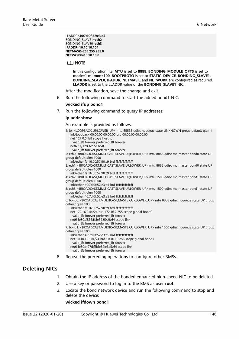
LLADDR=40:7d:0f:52:e3:a5BONDING_SLAVE1=eth2BONDING_SLAVE0=eth3IPADDR=10.10.10.104NETMASK=255.255.255.0NETWORK=10.10.10.0
In this configuration file, MTU is set to 8888, BONDING_MODULE_OPTS is set tomode=1 miimon=100, BOOTPROTO is set to STATIC. DEVICE, BONDING_SLAVE1,BONDING_SLAVE0, IPADDR, NETMASK, and NETWORK are configured as required.LLADDR is set to the LLADDR value of the BONDING_SLAVE1 NIC.
After the modification, save the change and exit.6. Run the following command to start the added bond1 NIC:
wicked ifup bond17. Run the following command to query IP addresses:
ip addr showAn example is provided as follows:1: lo: <LOOPBACK,UP,LOWER_UP> mtu 65536 qdisc noqueue state UNKNOWN group default qlen 1 link/loopback 00:00:00:00:00:00 brd 00:00:00:00:00:00 inet 127.0.0.1/8 scope host lo valid_lft forever preferred_lft forever inet6 ::1/128 scope host valid_lft forever preferred_lft forever2: eth0: <BROADCAST,MULTICAST,SLAVE,UP,LOWER_UP> mtu 8888 qdisc mq master bond0 state UP group default qlen 1000 link/ether fa:16:00:57:90:c9 brd ff:ff:ff:ff:ff:ff3: eth1: <BROADCAST,MULTICAST,SLAVE,UP,LOWER_UP> mtu 8888 qdisc mq master bond0 state UP group default qlen 1000 link/ether fa:16:00:57:90:c9 brd ff:ff:ff:ff:ff:ff4: eth2: <BROADCAST,MULTICAST,SLAVE,UP,LOWER_UP> mtu 1500 qdisc mq master bond1 state UP group default qlen 1000 link/ether 40:7d:0f:52:e3:a5 brd ff:ff:ff:ff:ff:ff5: eth3: <BROADCAST,MULTICAST,SLAVE,UP,LOWER_UP> mtu 1500 qdisc mq master bond1 state UP group default qlen 1000 link/ether 40:7d:0f:52:e3:a5 brd ff:ff:ff:ff:ff:ff6: bond0: <BROADCAST,MULTICAST,MASTER,UP,LOWER_UP> mtu 8888 qdisc noqueue state UP group default qlen 1000 link/ether fa:16:00:57:90:c9 brd ff:ff:ff:ff:ff:ff inet 172.16.2.44/24 brd 172.16.2.255 scope global bond0 valid_lft forever preferred_lft forever inet6 fe80::f816:ff:fe57:90c9/64 scope link valid_lft forever preferred_lft forever7: bond1: <BROADCAST,MULTICAST,MASTER,UP,LOWER_UP> mtu 1500 qdisc noqueue state UP group default qlen 1000 link/ether 40:7d:0f:52:e3:a5 brd ff:ff:ff:ff:ff:ff inet 10.10.10.104/24 brd 10.10.10.255 scope global bond1 valid_lft forever preferred_lft forever inet6 fe80::427d:fff:fe52:e3a5/64 scope link valid_lft forever preferred_lft forever
8. Repeat the preceding operations to configure other BMSs.
Deleting NICs1. Obtain the IP address of the bonded enhanced high-speed NIC to be deleted.2. Use a key or password to log in to the BMS as user root.3. Locate the bond network device and run the following command to stop and
delete the device:wicked ifdown bond1
Bare Metal ServerUser Guide 6 Network
Issue 22 (2020-01-20) Copyright © Huawei Technologies Co., Ltd. 146
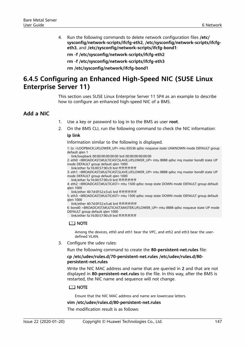
4. Run the following commands to delete network configuration files /etc/sysconfig/network-scripts/ifcfg-eth2, /etc/sysconfig/network-scripts/ifcfg-eth3, and /etc/sysconfig/network-scripts/ifcfg-bond1:rm -f /etc/sysconfig/network-scripts/ifcfg-eth2rm -f /etc/sysconfig/network-scripts/ifcfg-eth3rm /etc/sysconfig/network/ifcfg-bond1
6.4.5 Configuring an Enhanced High-Speed NIC (SUSE LinuxEnterprise Server 11)
This section uses SUSE Linux Enterprise Server 11 SP4 as an example to describehow to configure an enhanced high-speed NIC of a BMS.
Add a NIC1. Use a key or password to log in to the BMS as user root.2. On the BMS CLI, run the following command to check the NIC information:
ip linkInformation similar to the following is displayed.1: lo: <LOOPBACK,UP,LOWER_UP> mtu 65536 qdisc noqueue state UNKNOWN mode DEFAULT group default qlen 1 link/loopback 00:00:00:00:00:00 brd 00:00:00:00:00:002: eth0: <BROADCAST,MULTICAST,SLAVE,UP,LOWER_UP> mtu 8888 qdisc mq master bond0 state UP mode DEFAULT group default qlen 1000 link/ether fa:16:00:57:90:c9 brd ff:ff:ff:ff:ff:ff3: eth1: <BROADCAST,MULTICAST,SLAVE,UP,LOWER_UP> mtu 8888 qdisc mq master bond0 state UP mode DEFAULT group default qlen 1000 link/ether fa:16:00:57:90:c9 brd ff:ff:ff:ff:ff:ff4: eth2: <BROADCAST,MULTICAST> mtu 1500 qdisc noop state DOWN mode DEFAULT group default qlen 1000 link/ether 40:7d:0f:52:e3:a5 brd ff:ff:ff:ff:ff:ff5: eth3: <BROADCAST,MULTICAST> mtu 1500 qdisc noop state DOWN mode DEFAULT group default qlen 1000 link/ether 40:7d:0f:52:e3:a6 brd ff:ff:ff:ff:ff:ff6: bond0: <BROADCAST,MULTICAST,MASTER,UP,LOWER_UP> mtu 8888 qdisc noqueue state UP mode DEFAULT group default qlen 1000 link/ether fa:16:00:57:90:c9 brd ff:ff:ff:ff:ff:ff
Among the devices, eth0 and eth1 bear the VPC, and eth2 and eth3 bear the user-defined VLAN.
3. Configure the udev rules:Run the following command to create the 80-persistent-net.rules file:cp /etc/udev/rules.d/70-persistent-net.rules /etc/udev/rules.d/80-persistent-net.rulesWrite the NIC MAC address and name that are queried in 2 and that are notdisplayed in 80-persistent-net.rules to the file. In this way, after the BMS isrestarted, the NIC name and sequence will not change.
Ensure that the NIC MAC address and name are lowercase letters.
vim /etc/udev/rules.d/80-persistent-net.rulesThe modification result is as follows:
Bare Metal ServerUser Guide 6 Network
Issue 22 (2020-01-20) Copyright © Huawei Technologies Co., Ltd. 147
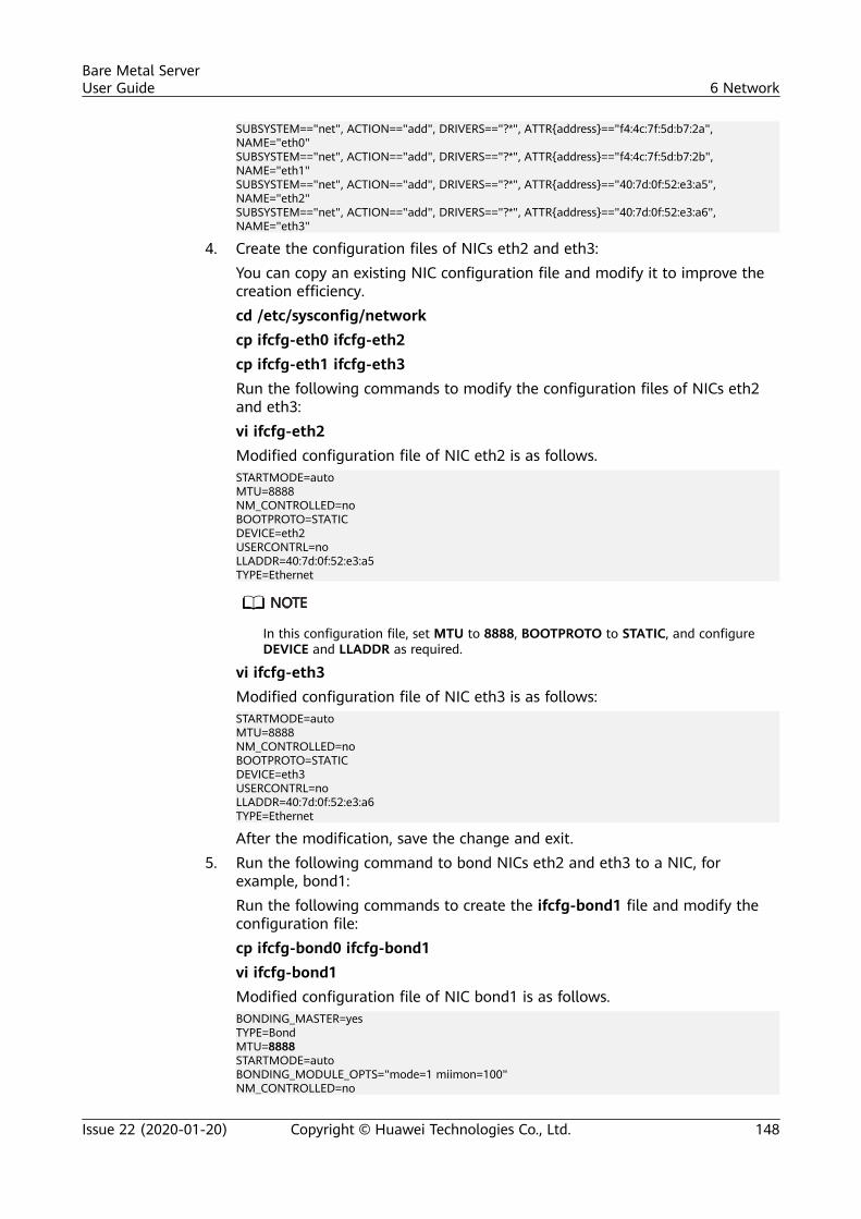
SUBSYSTEM=="net", ACTION=="add", DRIVERS=="?*", ATTR{address}=="f4:4c:7f:5d:b7:2a", NAME="eth0"SUBSYSTEM=="net", ACTION=="add", DRIVERS=="?*", ATTR{address}=="f4:4c:7f:5d:b7:2b", NAME="eth1"SUBSYSTEM=="net", ACTION=="add", DRIVERS=="?*", ATTR{address}=="40:7d:0f:52:e3:a5", NAME="eth2"SUBSYSTEM=="net", ACTION=="add", DRIVERS=="?*", ATTR{address}=="40:7d:0f:52:e3:a6", NAME="eth3"
4. Create the configuration files of NICs eth2 and eth3:You can copy an existing NIC configuration file and modify it to improve thecreation efficiency.cd /etc/sysconfig/networkcp ifcfg-eth0 ifcfg-eth2cp ifcfg-eth1 ifcfg-eth3Run the following commands to modify the configuration files of NICs eth2and eth3:vi ifcfg-eth2Modified configuration file of NIC eth2 is as follows.STARTMODE=autoMTU=8888NM_CONTROLLED=noBOOTPROTO=STATICDEVICE=eth2USERCONTRL=noLLADDR=40:7d:0f:52:e3:a5TYPE=Ethernet
In this configuration file, set MTU to 8888, BOOTPROTO to STATIC, and configureDEVICE and LLADDR as required.
vi ifcfg-eth3Modified configuration file of NIC eth3 is as follows:STARTMODE=autoMTU=8888NM_CONTROLLED=noBOOTPROTO=STATICDEVICE=eth3USERCONTRL=noLLADDR=40:7d:0f:52:e3:a6TYPE=Ethernet
After the modification, save the change and exit.5. Run the following command to bond NICs eth2 and eth3 to a NIC, for
example, bond1:Run the following commands to create the ifcfg-bond1 file and modify theconfiguration file:cp ifcfg-bond0 ifcfg-bond1vi ifcfg-bond1Modified configuration file of NIC bond1 is as follows.BONDING_MASTER=yesTYPE=BondMTU=8888STARTMODE=autoBONDING_MODULE_OPTS="mode=1 miimon=100"NM_CONTROLLED=no
Bare Metal ServerUser Guide 6 Network
Issue 22 (2020-01-20) Copyright © Huawei Technologies Co., Ltd. 148
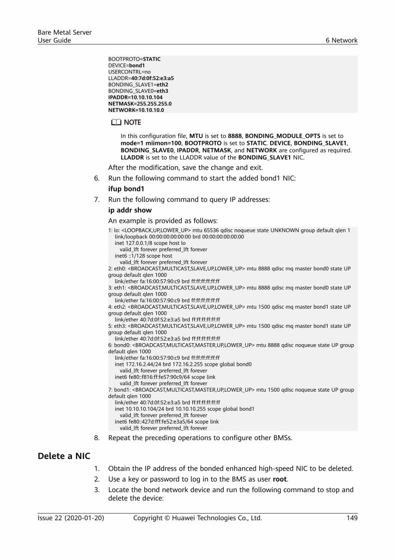
BOOTPROTO=STATICDEVICE=bond1USERCONTRL=noLLADDR=40:7d:0f:52:e3:a5BONDING_SLAVE1=eth2BONDING_SLAVE0=eth3IPADDR=10.10.10.104NETMASK=255.255.255.0NETWORK=10.10.10.0
In this configuration file, MTU is set to 8888, BONDING_MODULE_OPTS is set tomode=1 miimon=100, BOOTPROTO is set to STATIC. DEVICE, BONDING_SLAVE1,BONDING_SLAVE0, IPADDR, NETMASK, and NETWORK are configured as required.LLADDR is set to the LLADDR value of the BONDING_SLAVE1 NIC.
After the modification, save the change and exit.6. Run the following command to start the added bond1 NIC:
ifup bond17. Run the following command to query IP addresses:
ip addr showAn example is provided as follows:1: lo: <LOOPBACK,UP,LOWER_UP> mtu 65536 qdisc noqueue state UNKNOWN group default qlen 1 link/loopback 00:00:00:00:00:00 brd 00:00:00:00:00:00 inet 127.0.0.1/8 scope host lo valid_lft forever preferred_lft forever inet6 ::1/128 scope host valid_lft forever preferred_lft forever2: eth0: <BROADCAST,MULTICAST,SLAVE,UP,LOWER_UP> mtu 8888 qdisc mq master bond0 state UP group default qlen 1000 link/ether fa:16:00:57:90:c9 brd ff:ff:ff:ff:ff:ff3: eth1: <BROADCAST,MULTICAST,SLAVE,UP,LOWER_UP> mtu 8888 qdisc mq master bond0 state UP group default qlen 1000 link/ether fa:16:00:57:90:c9 brd ff:ff:ff:ff:ff:ff4: eth2: <BROADCAST,MULTICAST,SLAVE,UP,LOWER_UP> mtu 1500 qdisc mq master bond1 state UP group default qlen 1000 link/ether 40:7d:0f:52:e3:a5 brd ff:ff:ff:ff:ff:ff5: eth3: <BROADCAST,MULTICAST,SLAVE,UP,LOWER_UP> mtu 1500 qdisc mq master bond1 state UP group default qlen 1000 link/ether 40:7d:0f:52:e3:a5 brd ff:ff:ff:ff:ff:ff6: bond0: <BROADCAST,MULTICAST,MASTER,UP,LOWER_UP> mtu 8888 qdisc noqueue state UP group default qlen 1000 link/ether fa:16:00:57:90:c9 brd ff:ff:ff:ff:ff:ff inet 172.16.2.44/24 brd 172.16.2.255 scope global bond0 valid_lft forever preferred_lft forever inet6 fe80::f816:ff:fe57:90c9/64 scope link valid_lft forever preferred_lft forever7: bond1: <BROADCAST,MULTICAST,MASTER,UP,LOWER_UP> mtu 1500 qdisc noqueue state UP group default qlen 1000 link/ether 40:7d:0f:52:e3:a5 brd ff:ff:ff:ff:ff:ff inet 10.10.10.104/24 brd 10.10.10.255 scope global bond1 valid_lft forever preferred_lft forever inet6 fe80::427d:fff:fe52:e3a5/64 scope link valid_lft forever preferred_lft forever
8. Repeat the preceding operations to configure other BMSs.
Delete a NIC1. Obtain the IP address of the bonded enhanced high-speed NIC to be deleted.2. Use a key or password to log in to the BMS as user root.3. Locate the bond network device and run the following command to stop and
delete the device:
Bare Metal ServerUser Guide 6 Network
Issue 22 (2020-01-20) Copyright © Huawei Technologies Co., Ltd. 149
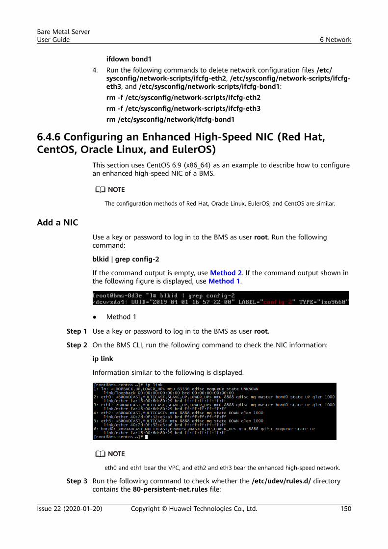
ifdown bond14. Run the following commands to delete network configuration files /etc/
sysconfig/network-scripts/ifcfg-eth2, /etc/sysconfig/network-scripts/ifcfg-eth3, and /etc/sysconfig/network-scripts/ifcfg-bond1:rm -f /etc/sysconfig/network-scripts/ifcfg-eth2rm -f /etc/sysconfig/network-scripts/ifcfg-eth3rm /etc/sysconfig/network/ifcfg-bond1
6.4.6 Configuring an Enhanced High-Speed NIC (Red Hat,CentOS, Oracle Linux, and EulerOS)
This section uses CentOS 6.9 (x86_64) as an example to describe how to configurean enhanced high-speed NIC of a BMS.
The configuration methods of Red Hat, Oracle Linux, EulerOS, and CentOS are similar.
Add a NIC
Use a key or password to log in to the BMS as user root. Run the followingcommand:
blkid | grep config-2
If the command output is empty, use Method 2. If the command output shown inthe following figure is displayed, use Method 1.
● Method 1
Step 1 Use a key or password to log in to the BMS as user root.
Step 2 On the BMS CLI, run the following command to check the NIC information:
ip link
Information similar to the following is displayed.
eth0 and eth1 bear the VPC, and eth2 and eth3 bear the enhanced high-speed network.
Step 3 Run the following command to check whether the /etc/udev/rules.d/ directorycontains the 80-persistent-net.rules file:
Bare Metal ServerUser Guide 6 Network
Issue 22 (2020-01-20) Copyright © Huawei Technologies Co., Ltd. 150
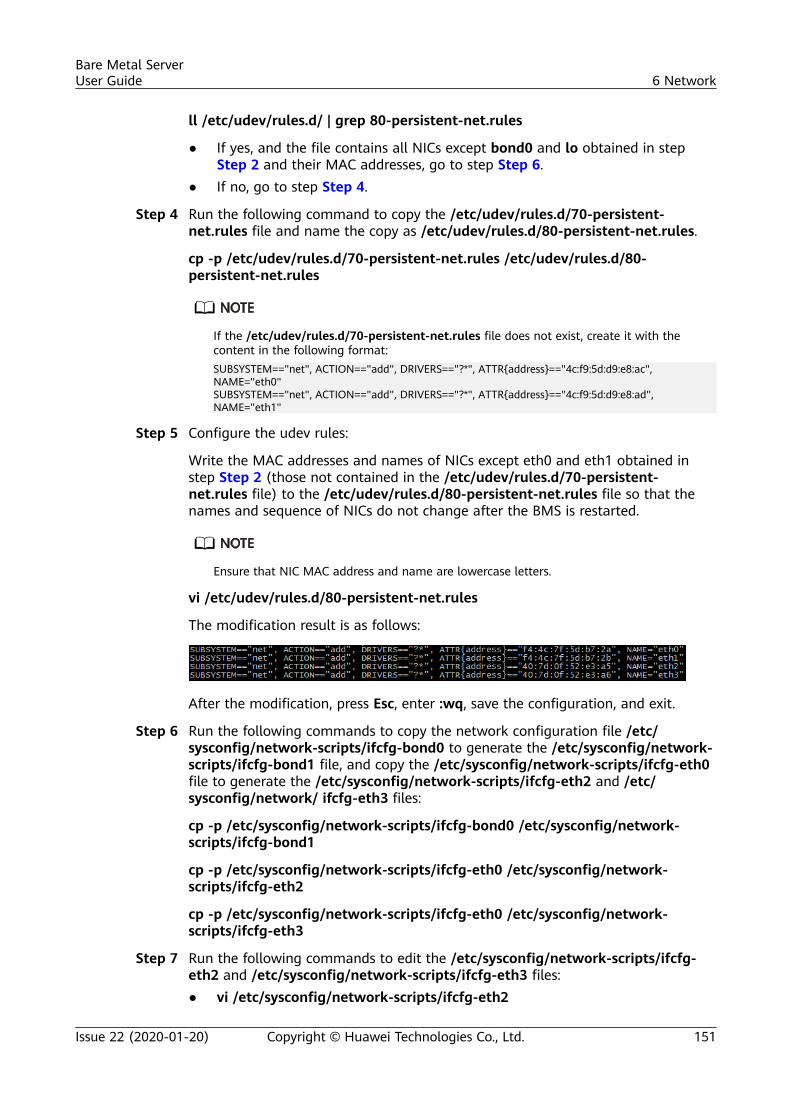
ll /etc/udev/rules.d/ | grep 80-persistent-net.rules
● If yes, and the file contains all NICs except bond0 and lo obtained in stepStep 2 and their MAC addresses, go to step Step 6.
● If no, go to step Step 4.
Step 4 Run the following command to copy the /etc/udev/rules.d/70-persistent-net.rules file and name the copy as /etc/udev/rules.d/80-persistent-net.rules.
cp -p /etc/udev/rules.d/70-persistent-net.rules /etc/udev/rules.d/80-persistent-net.rules
If the /etc/udev/rules.d/70-persistent-net.rules file does not exist, create it with thecontent in the following format:SUBSYSTEM=="net", ACTION=="add", DRIVERS=="?*", ATTR{address}=="4c:f9:5d:d9:e8:ac", NAME="eth0"SUBSYSTEM=="net", ACTION=="add", DRIVERS=="?*", ATTR{address}=="4c:f9:5d:d9:e8:ad", NAME="eth1"
Step 5 Configure the udev rules:
Write the MAC addresses and names of NICs except eth0 and eth1 obtained instep Step 2 (those not contained in the /etc/udev/rules.d/70-persistent-net.rules file) to the /etc/udev/rules.d/80-persistent-net.rules file so that thenames and sequence of NICs do not change after the BMS is restarted.
Ensure that NIC MAC address and name are lowercase letters.
vi /etc/udev/rules.d/80-persistent-net.rules
The modification result is as follows:
After the modification, press Esc, enter :wq, save the configuration, and exit.
Step 6 Run the following commands to copy the network configuration file /etc/sysconfig/network-scripts/ifcfg-bond0 to generate the /etc/sysconfig/network-scripts/ifcfg-bond1 file, and copy the /etc/sysconfig/network-scripts/ifcfg-eth0file to generate the /etc/sysconfig/network-scripts/ifcfg-eth2 and /etc/sysconfig/network/ ifcfg-eth3 files:
cp -p /etc/sysconfig/network-scripts/ifcfg-bond0 /etc/sysconfig/network-scripts/ifcfg-bond1
cp -p /etc/sysconfig/network-scripts/ifcfg-eth0 /etc/sysconfig/network-scripts/ifcfg-eth2
cp -p /etc/sysconfig/network-scripts/ifcfg-eth0 /etc/sysconfig/network-scripts/ifcfg-eth3
Step 7 Run the following commands to edit the /etc/sysconfig/network-scripts/ifcfg-eth2 and /etc/sysconfig/network-scripts/ifcfg-eth3 files:● vi /etc/sysconfig/network-scripts/ifcfg-eth2
Bare Metal ServerUser Guide 6 Network
Issue 22 (2020-01-20) Copyright © Huawei Technologies Co., Ltd. 151
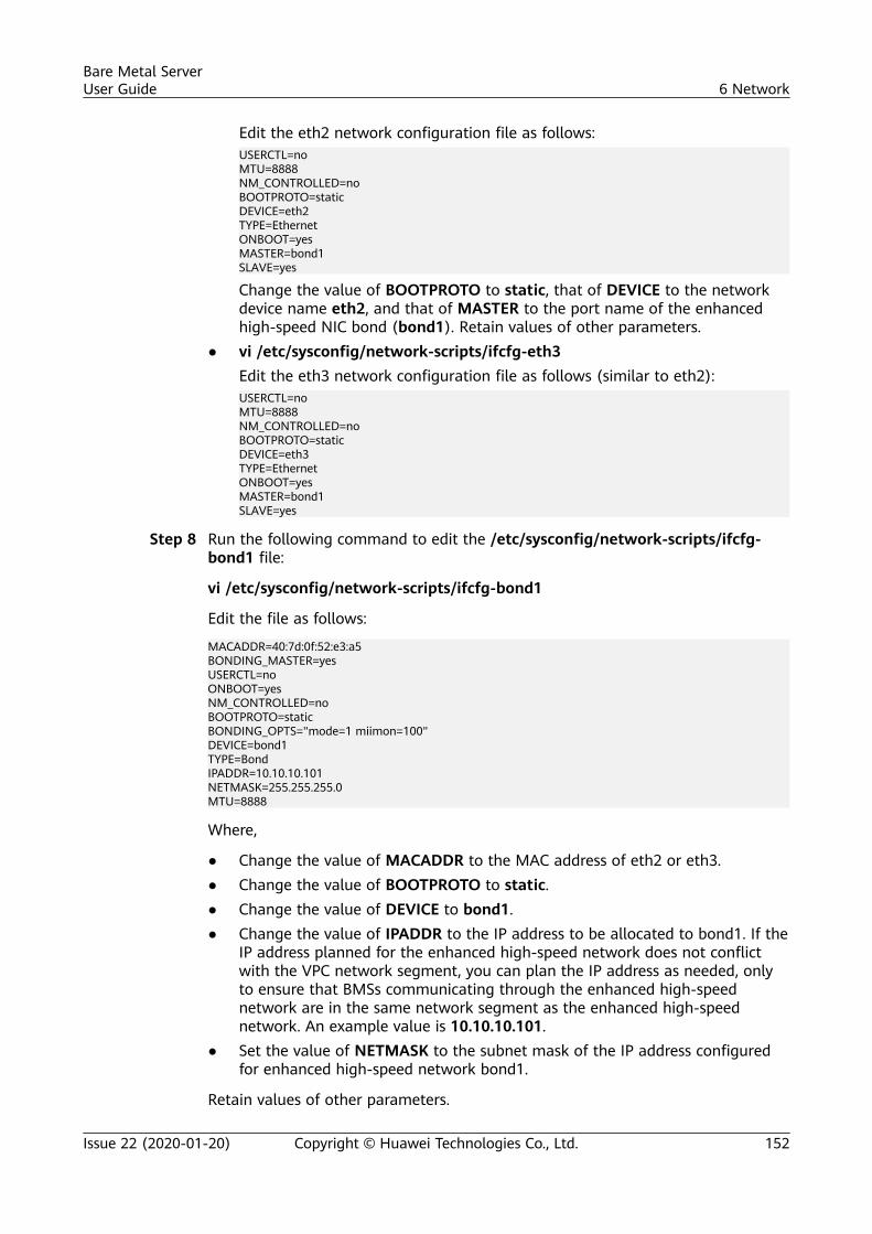
Edit the eth2 network configuration file as follows:USERCTL=noMTU=8888NM_CONTROLLED=noBOOTPROTO=staticDEVICE=eth2TYPE=EthernetONBOOT=yesMASTER=bond1SLAVE=yes
Change the value of BOOTPROTO to static, that of DEVICE to the networkdevice name eth2, and that of MASTER to the port name of the enhancedhigh-speed NIC bond (bond1). Retain values of other parameters.
● vi /etc/sysconfig/network-scripts/ifcfg-eth3Edit the eth3 network configuration file as follows (similar to eth2):USERCTL=noMTU=8888NM_CONTROLLED=noBOOTPROTO=staticDEVICE=eth3TYPE=EthernetONBOOT=yesMASTER=bond1SLAVE=yes
Step 8 Run the following command to edit the /etc/sysconfig/network-scripts/ifcfg-bond1 file:
vi /etc/sysconfig/network-scripts/ifcfg-bond1
Edit the file as follows:
MACADDR=40:7d:0f:52:e3:a5BONDING_MASTER=yesUSERCTL=noONBOOT=yesNM_CONTROLLED=noBOOTPROTO=staticBONDING_OPTS="mode=1 miimon=100"DEVICE=bond1TYPE=BondIPADDR=10.10.10.101NETMASK=255.255.255.0MTU=8888
Where,
● Change the value of MACADDR to the MAC address of eth2 or eth3.● Change the value of BOOTPROTO to static.● Change the value of DEVICE to bond1.● Change the value of IPADDR to the IP address to be allocated to bond1. If the
IP address planned for the enhanced high-speed network does not conflictwith the VPC network segment, you can plan the IP address as needed, onlyto ensure that BMSs communicating through the enhanced high-speednetwork are in the same network segment as the enhanced high-speednetwork. An example value is 10.10.10.101.
● Set the value of NETMASK to the subnet mask of the IP address configuredfor enhanced high-speed network bond1.
Retain values of other parameters.
Bare Metal ServerUser Guide 6 Network
Issue 22 (2020-01-20) Copyright © Huawei Technologies Co., Ltd. 152
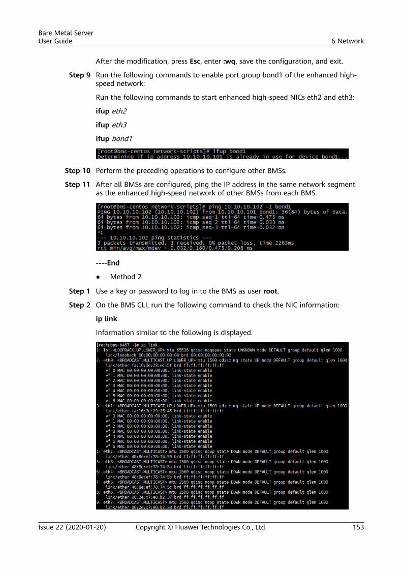
After the modification, press Esc, enter :wq, save the configuration, and exit.
Step 9 Run the following commands to enable port group bond1 of the enhanced high-speed network:
Run the following commands to start enhanced high-speed NICs eth2 and eth3:
ifup eth2
ifup eth3
ifup bond1
Step 10 Perform the preceding operations to configure other BMSs.
Step 11 After all BMSs are configured, ping the IP address in the same network segmentas the enhanced high-speed network of other BMSs from each BMS.
----End
● Method 2
Step 1 Use a key or password to log in to the BMS as user root.
Step 2 On the BMS CLI, run the following command to check the NIC information:
ip link
Information similar to the following is displayed.
Bare Metal ServerUser Guide 6 Network
Issue 22 (2020-01-20) Copyright © Huawei Technologies Co., Ltd. 153
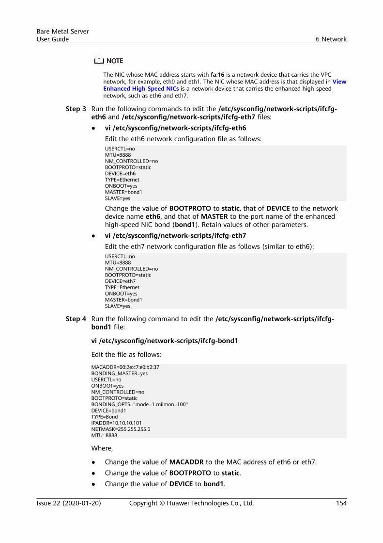
The NIC whose MAC address starts with fa:16 is a network device that carries the VPCnetwork, for example, eth0 and eth1. The NIC whose MAC address is that displayed in ViewEnhanced High-Speed NICs is a network device that carries the enhanced high-speednetwork, such as eth6 and eth7.
Step 3 Run the following commands to edit the /etc/sysconfig/network-scripts/ifcfg-eth6 and /etc/sysconfig/network-scripts/ifcfg-eth7 files:● vi /etc/sysconfig/network-scripts/ifcfg-eth6
Edit the eth6 network configuration file as follows:USERCTL=noMTU=8888NM_CONTROLLED=noBOOTPROTO=staticDEVICE=eth6TYPE=EthernetONBOOT=yesMASTER=bond1SLAVE=yes
Change the value of BOOTPROTO to static, that of DEVICE to the networkdevice name eth6, and that of MASTER to the port name of the enhancedhigh-speed NIC bond (bond1). Retain values of other parameters.
● vi /etc/sysconfig/network-scripts/ifcfg-eth7Edit the eth7 network configuration file as follows (similar to eth6):USERCTL=noMTU=8888NM_CONTROLLED=noBOOTPROTO=staticDEVICE=eth7TYPE=EthernetONBOOT=yesMASTER=bond1SLAVE=yes
Step 4 Run the following command to edit the /etc/sysconfig/network-scripts/ifcfg-bond1 file:
vi /etc/sysconfig/network-scripts/ifcfg-bond1
Edit the file as follows:
MACADDR=00:2e:c7:e0:b2:37BONDING_MASTER=yesUSERCTL=noONBOOT=yesNM_CONTROLLED=noBOOTPROTO=staticBONDING_OPTS="mode=1 miimon=100"DEVICE=bond1TYPE=BondIPADDR=10.10.10.101NETMASK=255.255.255.0MTU=8888
Where,
● Change the value of MACADDR to the MAC address of eth6 or eth7.● Change the value of BOOTPROTO to static.● Change the value of DEVICE to bond1.
Bare Metal ServerUser Guide 6 Network
Issue 22 (2020-01-20) Copyright © Huawei Technologies Co., Ltd. 154
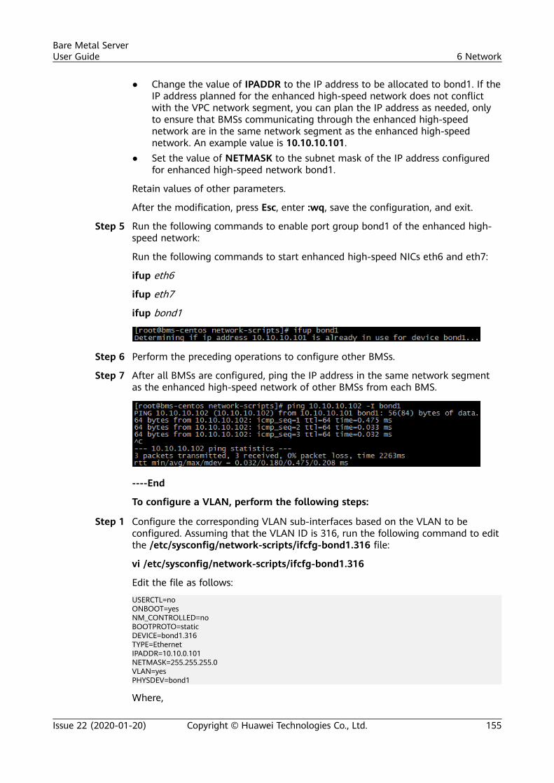
● Change the value of IPADDR to the IP address to be allocated to bond1. If theIP address planned for the enhanced high-speed network does not conflictwith the VPC network segment, you can plan the IP address as needed, onlyto ensure that BMSs communicating through the enhanced high-speednetwork are in the same network segment as the enhanced high-speednetwork. An example value is 10.10.10.101.
● Set the value of NETMASK to the subnet mask of the IP address configuredfor enhanced high-speed network bond1.
Retain values of other parameters.
After the modification, press Esc, enter :wq, save the configuration, and exit.
Step 5 Run the following commands to enable port group bond1 of the enhanced high-speed network:
Run the following commands to start enhanced high-speed NICs eth6 and eth7:
ifup eth6
ifup eth7
ifup bond1
Step 6 Perform the preceding operations to configure other BMSs.
Step 7 After all BMSs are configured, ping the IP address in the same network segmentas the enhanced high-speed network of other BMSs from each BMS.
----End
To configure a VLAN, perform the following steps:
Step 1 Configure the corresponding VLAN sub-interfaces based on the VLAN to beconfigured. Assuming that the VLAN ID is 316, run the following command to editthe /etc/sysconfig/network-scripts/ifcfg-bond1.316 file:
vi /etc/sysconfig/network-scripts/ifcfg-bond1.316
Edit the file as follows:
USERCTL=noONBOOT=yesNM_CONTROLLED=noBOOTPROTO=staticDEVICE=bond1.316TYPE=EthernetIPADDR=10.10.0.101NETMASK=255.255.255.0VLAN=yesPHYSDEV=bond1
Where,
Bare Metal ServerUser Guide 6 Network
Issue 22 (2020-01-20) Copyright © Huawei Technologies Co., Ltd. 155
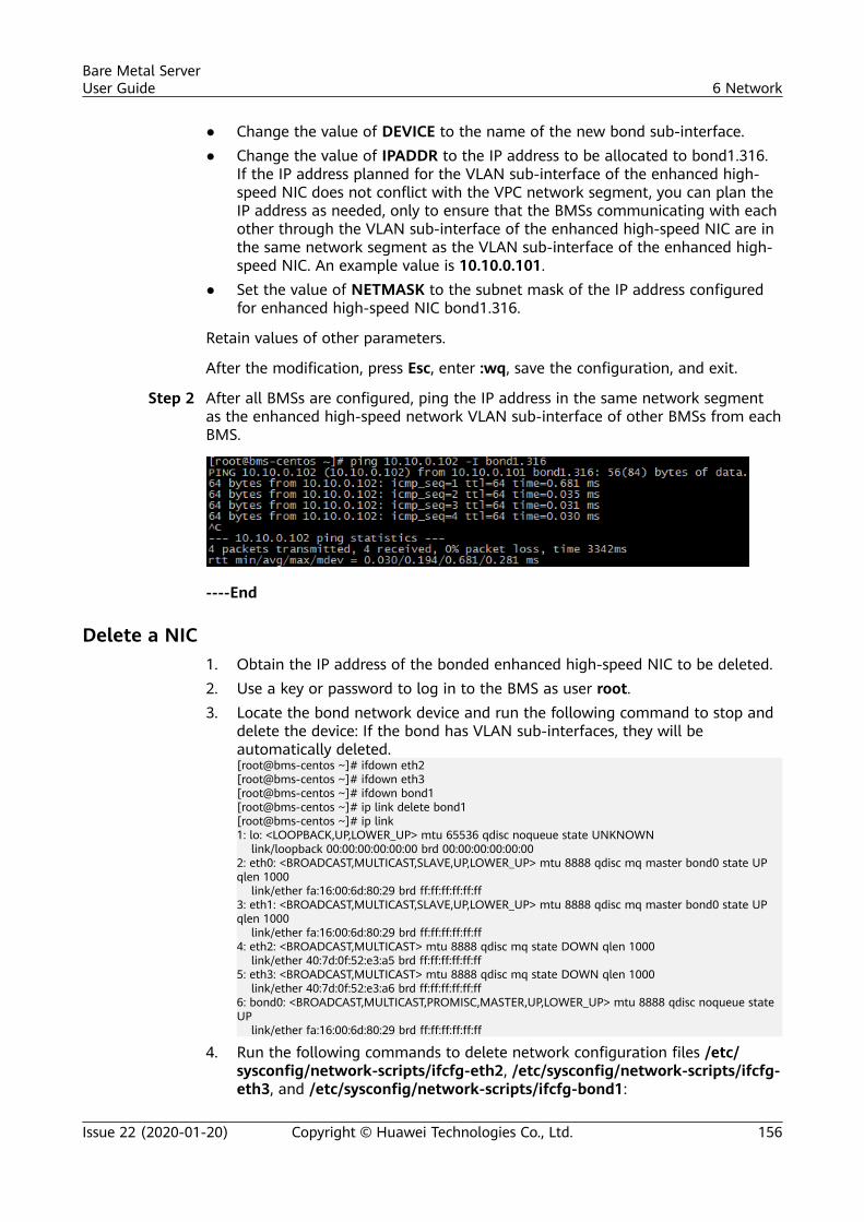
● Change the value of DEVICE to the name of the new bond sub-interface.● Change the value of IPADDR to the IP address to be allocated to bond1.316.
If the IP address planned for the VLAN sub-interface of the enhanced high-speed NIC does not conflict with the VPC network segment, you can plan theIP address as needed, only to ensure that the BMSs communicating with eachother through the VLAN sub-interface of the enhanced high-speed NIC are inthe same network segment as the VLAN sub-interface of the enhanced high-speed NIC. An example value is 10.10.0.101.
● Set the value of NETMASK to the subnet mask of the IP address configuredfor enhanced high-speed NIC bond1.316.
Retain values of other parameters.
After the modification, press Esc, enter :wq, save the configuration, and exit.
Step 2 After all BMSs are configured, ping the IP address in the same network segmentas the enhanced high-speed network VLAN sub-interface of other BMSs from eachBMS.
----End
Delete a NIC1. Obtain the IP address of the bonded enhanced high-speed NIC to be deleted.2. Use a key or password to log in to the BMS as user root.3. Locate the bond network device and run the following command to stop and
delete the device: If the bond has VLAN sub-interfaces, they will beautomatically deleted.[root@bms-centos ~]# ifdown eth2[root@bms-centos ~]# ifdown eth3[root@bms-centos ~]# ifdown bond1[root@bms-centos ~]# ip link delete bond1[root@bms-centos ~]# ip link1: lo: <LOOPBACK,UP,LOWER_UP> mtu 65536 qdisc noqueue state UNKNOWN link/loopback 00:00:00:00:00:00 brd 00:00:00:00:00:002: eth0: <BROADCAST,MULTICAST,SLAVE,UP,LOWER_UP> mtu 8888 qdisc mq master bond0 state UP qlen 1000 link/ether fa:16:00:6d:80:29 brd ff:ff:ff:ff:ff:ff3: eth1: <BROADCAST,MULTICAST,SLAVE,UP,LOWER_UP> mtu 8888 qdisc mq master bond0 state UP qlen 1000 link/ether fa:16:00:6d:80:29 brd ff:ff:ff:ff:ff:ff4: eth2: <BROADCAST,MULTICAST> mtu 8888 qdisc mq state DOWN qlen 1000 link/ether 40:7d:0f:52:e3:a5 brd ff:ff:ff:ff:ff:ff5: eth3: <BROADCAST,MULTICAST> mtu 8888 qdisc mq state DOWN qlen 1000 link/ether 40:7d:0f:52:e3:a6 brd ff:ff:ff:ff:ff:ff6: bond0: <BROADCAST,MULTICAST,PROMISC,MASTER,UP,LOWER_UP> mtu 8888 qdisc noqueue state UP link/ether fa:16:00:6d:80:29 brd ff:ff:ff:ff:ff:ff
4. Run the following commands to delete network configuration files /etc/sysconfig/network-scripts/ifcfg-eth2, /etc/sysconfig/network-scripts/ifcfg-eth3, and /etc/sysconfig/network-scripts/ifcfg-bond1:
Bare Metal ServerUser Guide 6 Network
Issue 22 (2020-01-20) Copyright © Huawei Technologies Co., Ltd. 156
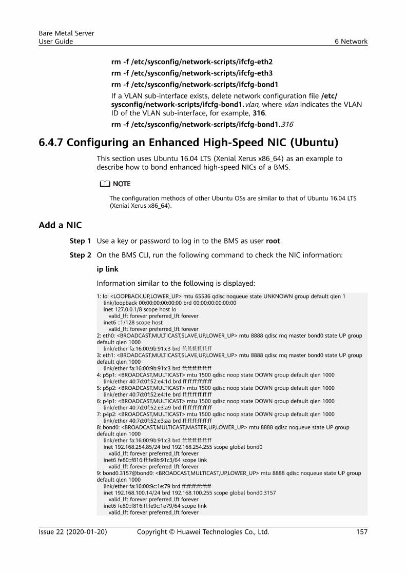
rm -f /etc/sysconfig/network-scripts/ifcfg-eth2rm -f /etc/sysconfig/network-scripts/ifcfg-eth3rm -f /etc/sysconfig/network-scripts/ifcfg-bond1If a VLAN sub-interface exists, delete network configuration file /etc/sysconfig/network-scripts/ifcfg-bond1.vlan, where vlan indicates the VLANID of the VLAN sub-interface, for example, 316.rm -f /etc/sysconfig/network-scripts/ifcfg-bond1.316
6.4.7 Configuring an Enhanced High-Speed NIC (Ubuntu)This section uses Ubuntu 16.04 LTS (Xenial Xerus x86_64) as an example todescribe how to bond enhanced high-speed NICs of a BMS.
The configuration methods of other Ubuntu OSs are similar to that of Ubuntu 16.04 LTS(Xenial Xerus x86_64).
Add a NIC
Step 1 Use a key or password to log in to the BMS as user root.
Step 2 On the BMS CLI, run the following command to check the NIC information:
ip link
Information similar to the following is displayed:
1: lo: <LOOPBACK,UP,LOWER_UP> mtu 65536 qdisc noqueue state UNKNOWN group default qlen 1 link/loopback 00:00:00:00:00:00 brd 00:00:00:00:00:00 inet 127.0.0.1/8 scope host lo valid_lft forever preferred_lft forever inet6 ::1/128 scope host valid_lft forever preferred_lft forever2: eth0: <BROADCAST,MULTICAST,SLAVE,UP,LOWER_UP> mtu 8888 qdisc mq master bond0 state UP group default qlen 1000 link/ether fa:16:00:9b:91:c3 brd ff:ff:ff:ff:ff:ff3: eth1: <BROADCAST,MULTICAST,SLAVE,UP,LOWER_UP> mtu 8888 qdisc mq master bond0 state UP group default qlen 1000 link/ether fa:16:00:9b:91:c3 brd ff:ff:ff:ff:ff:ff4: p5p1: <BROADCAST,MULTICAST> mtu 1500 qdisc noop state DOWN group default qlen 1000 link/ether 40:7d:0f:52:e4:1d brd ff:ff:ff:ff:ff:ff5: p5p2: <BROADCAST,MULTICAST> mtu 1500 qdisc noop state DOWN group default qlen 1000 link/ether 40:7d:0f:52:e4:1e brd ff:ff:ff:ff:ff:ff6: p4p1: <BROADCAST,MULTICAST> mtu 1500 qdisc noop state DOWN group default qlen 1000 link/ether 40:7d:0f:52:e3:a9 brd ff:ff:ff:ff:ff:ff7: p4p2: <BROADCAST,MULTICAST> mtu 1500 qdisc noop state DOWN group default qlen 1000 link/ether 40:7d:0f:52:e3:aa brd ff:ff:ff:ff:ff:ff8: bond0: <BROADCAST,MULTICAST,MASTER,UP,LOWER_UP> mtu 8888 qdisc noqueue state UP group default qlen 1000 link/ether fa:16:00:9b:91:c3 brd ff:ff:ff:ff:ff:ff inet 192.168.254.85/24 brd 192.168.254.255 scope global bond0 valid_lft forever preferred_lft forever inet6 fe80::f816:ff:fe9b:91c3/64 scope link valid_lft forever preferred_lft forever9: bond0.3157@bond0: <BROADCAST,MULTICAST,UP,LOWER_UP> mtu 8888 qdisc noqueue state UP group default qlen 1000 link/ether fa:16:00:9c:1e:79 brd ff:ff:ff:ff:ff:ff inet 192.168.100.14/24 brd 192.168.100.255 scope global bond0.3157 valid_lft forever preferred_lft forever inet6 fe80::f816:ff:fe9c:1e79/64 scope link valid_lft forever preferred_lft forever
Bare Metal ServerUser Guide 6 Network
Issue 22 (2020-01-20) Copyright © Huawei Technologies Co., Ltd. 157
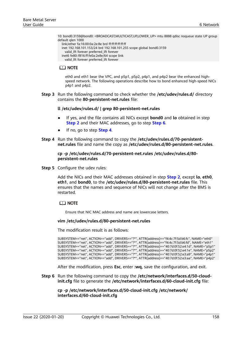
10: bond0.3159@bond0: <BROADCAST,MULTICAST,UP,LOWER_UP> mtu 8888 qdisc noqueue state UP group default qlen 1000 link/ether fa:16:00:0a:2e:8e brd ff:ff:ff:ff:ff:ff inet 192.168.101.153/24 brd 192.168.101.255 scope global bond0.3159 valid_lft forever preferred_lft forever inet6 fe80::f816:ff:fe0a:2e8e/64 scope link valid_lft forever preferred_lft forever
eth0 and eth1 bear the VPC, and p5p1, p5p2, p4p1, and p4p2 bear the enhanced high-speed network. The following operations describe how to bond enhanced high-speed NICsp4p1 and p4p2.
Step 3 Run the following command to check whether the /etc/udev/rules.d/ directorycontains the 80-persistent-net.rules file:
ll /etc/udev/rules.d/ | grep 80-persistent-net.rules
● If yes, and the file contains all NICs except bond0 and lo obtained in stepStep 2 and their MAC addresses, go to step Step 6.
● If no, go to step Step 4.
Step 4 Run the following command to copy the /etc/udev/rules.d/70-persistent-net.rules file and name the copy as /etc/udev/rules.d/80-persistent-net.rules.
cp -p /etc/udev/rules.d/70-persistent-net.rules /etc/udev/rules.d/80-persistent-net.rules
Step 5 Configure the udev rules:
Add the NICs and their MAC addresses obtained in step Step 2, except lo, eth0,eth1, and bond0, to the /etc/udev/rules.d/80-persistent-net.rules file. Thisensures that the names and sequence of NICs will not change after the BMS isrestarted.
Ensure that NIC MAC address and name are lowercase letters.
vim /etc/udev/rules.d/80-persistent-net.rules
The modification result is as follows:
SUBSYSTEM=="net", ACTION=="add", DRIVERS=="?*", ATTR{address}=="f4:4c:7f:5d:b6:fc", NAME="eth0"SUBSYSTEM=="net", ACTION=="add", DRIVERS=="?*", ATTR{address}=="f4:4c:7f:5d:b6:fd", NAME="eth1"SUBSYSTEM=="net", ACTION=="add", DRIVERS=="?*", ATTR{address}=="40:7d:0f:52:e4:1d", NAME="p5p1"SUBSYSTEM=="net", ACTION=="add", DRIVERS=="?*", ATTR{address}=="40:7d:0f:52:e4:1e", NAME="p5p2"SUBSYSTEM=="net", ACTION=="add", DRIVERS=="?*", ATTR{address}=="40:7d:0f:52:e3:a9", NAME="p4p1"SUBSYSTEM=="net", ACTION=="add", DRIVERS=="?*", ATTR{address}=="40:7d:0f:52:e3:aa", NAME="p4p2"
After the modification, press Esc, enter :wq, save the configuration, and exit.
Step 6 Run the following command to copy the /etc/network/interfaces.d/50-cloud-init.cfg file to generate the /etc/network/interfaces.d/60-cloud-init.cfg file:
cp -p /etc/network/interfaces.d/50-cloud-init.cfg /etc/network/interfaces.d/60-cloud-init.cfg
Bare Metal ServerUser Guide 6 Network
Issue 22 (2020-01-20) Copyright © Huawei Technologies Co., Ltd. 158
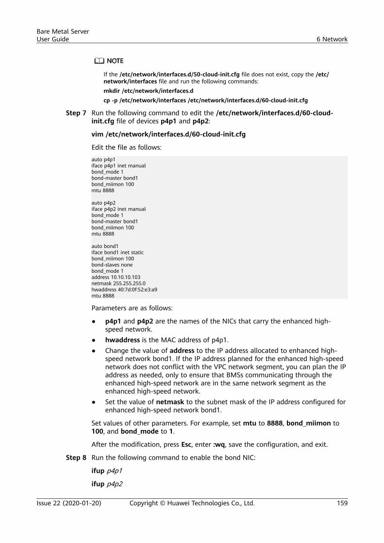
If the /etc/network/interfaces.d/50-cloud-init.cfg file does not exist, copy the /etc/network/interfaces file and run the following commands:mkdir /etc/network/interfaces.dcp -p /etc/network/interfaces /etc/network/interfaces.d/60-cloud-init.cfg
Step 7 Run the following command to edit the /etc/network/interfaces.d/60-cloud-init.cfg file of devices p4p1 and p4p2:
vim /etc/network/interfaces.d/60-cloud-init.cfg
Edit the file as follows:
auto p4p1iface p4p1 inet manualbond_mode 1bond-master bond1bond_miimon 100mtu 8888
auto p4p2iface p4p2 inet manualbond_mode 1bond-master bond1bond_miimon 100mtu 8888
auto bond1iface bond1 inet staticbond_miimon 100bond-slaves nonebond_mode 1address 10.10.10.103netmask 255.255.255.0hwaddress 40:7d:0f:52:e3:a9mtu 8888
Parameters are as follows:
● p4p1 and p4p2 are the names of the NICs that carry the enhanced high-speed network.
● hwaddress is the MAC address of p4p1.● Change the value of address to the IP address allocated to enhanced high-
speed network bond1. If the IP address planned for the enhanced high-speednetwork does not conflict with the VPC network segment, you can plan the IPaddress as needed, only to ensure that BMSs communicating through theenhanced high-speed network are in the same network segment as theenhanced high-speed network.
● Set the value of netmask to the subnet mask of the IP address configured forenhanced high-speed network bond1.
Set values of other parameters. For example, set mtu to 8888, bond_miimon to100, and bond_mode to 1.
After the modification, press Esc, enter :wq, save the configuration, and exit.
Step 8 Run the following command to enable the bond NIC:
ifup p4p1
ifup p4p2
Bare Metal ServerUser Guide 6 Network
Issue 22 (2020-01-20) Copyright © Huawei Technologies Co., Ltd. 159
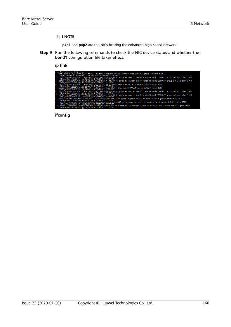
p4p1 and p4p2 are the NICs bearing the enhanced high-speed network.
Step 9 Run the following commands to check the NIC device status and whether thebond1 configuration file takes effect:
ip link
ifconfig
Bare Metal ServerUser Guide 6 Network
Issue 22 (2020-01-20) Copyright © Huawei Technologies Co., Ltd. 160
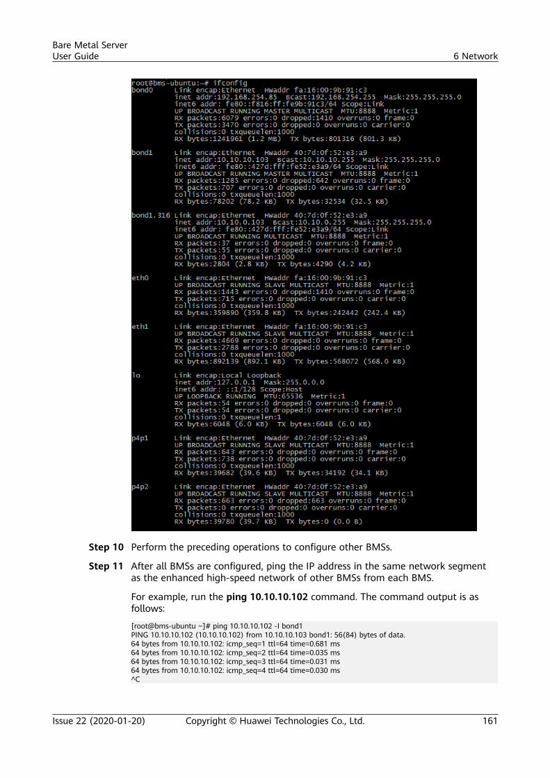
Step 10 Perform the preceding operations to configure other BMSs.
Step 11 After all BMSs are configured, ping the IP address in the same network segmentas the enhanced high-speed network of other BMSs from each BMS.
For example, run the ping 10.10.10.102 command. The command output is asfollows:
[root@bms-ubuntu ~]# ping 10.10.10.102 -I bond1PING 10.10.10.102 (10.10.10.102) from 10.10.10.103 bond1: 56(84) bytes of data.64 bytes from 10.10.10.102: icmp_seq=1 ttl=64 time=0.681 ms64 bytes from 10.10.10.102: icmp_seq=2 ttl=64 time=0.035 ms64 bytes from 10.10.10.102: icmp_seq=3 ttl=64 time=0.031 ms64 bytes from 10.10.10.102: icmp_seq=4 ttl=64 time=0.030 ms^C
Bare Metal ServerUser Guide 6 Network
Issue 22 (2020-01-20) Copyright © Huawei Technologies Co., Ltd. 161
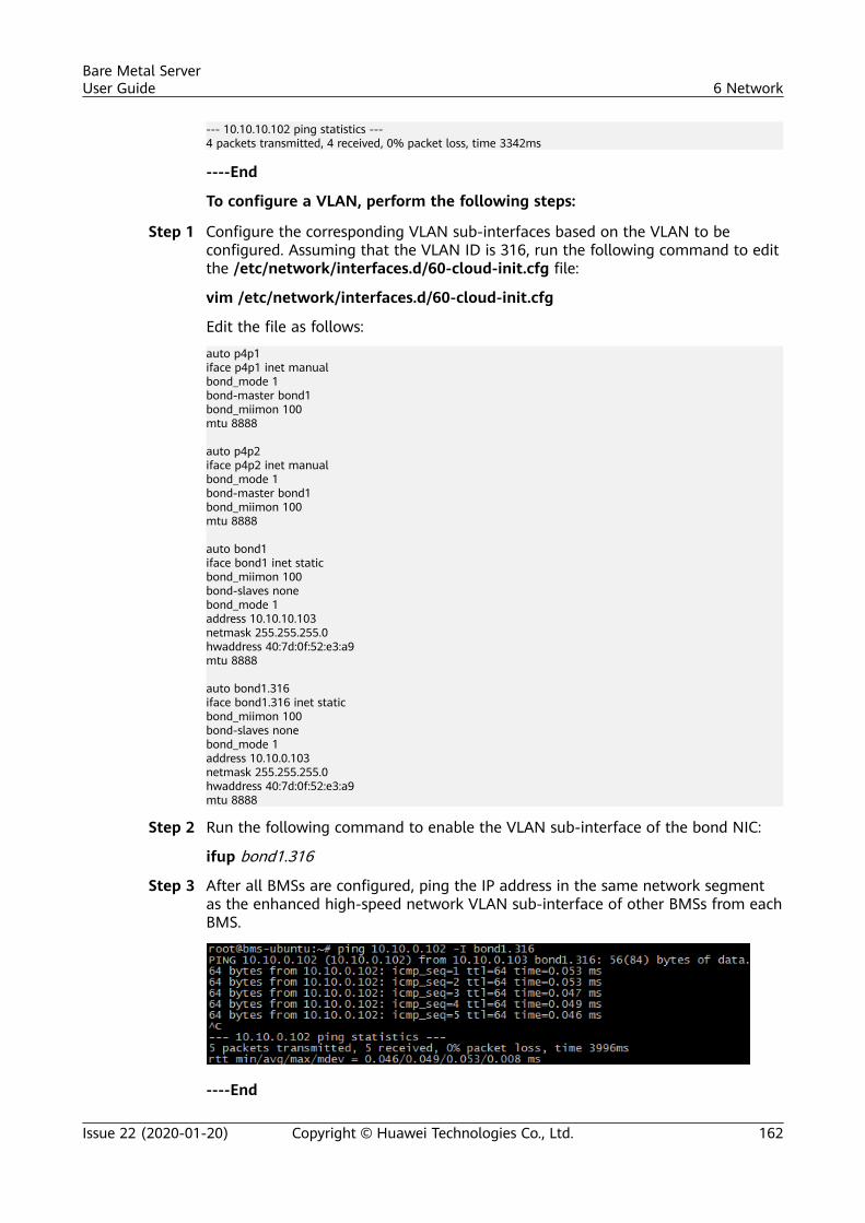
--- 10.10.10.102 ping statistics ---4 packets transmitted, 4 received, 0% packet loss, time 3342ms
----End
To configure a VLAN, perform the following steps:
Step 1 Configure the corresponding VLAN sub-interfaces based on the VLAN to beconfigured. Assuming that the VLAN ID is 316, run the following command to editthe /etc/network/interfaces.d/60-cloud-init.cfg file:
vim /etc/network/interfaces.d/60-cloud-init.cfg
Edit the file as follows:
auto p4p1iface p4p1 inet manualbond_mode 1bond-master bond1bond_miimon 100mtu 8888
auto p4p2iface p4p2 inet manualbond_mode 1bond-master bond1bond_miimon 100mtu 8888
auto bond1iface bond1 inet staticbond_miimon 100bond-slaves nonebond_mode 1address 10.10.10.103netmask 255.255.255.0hwaddress 40:7d:0f:52:e3:a9mtu 8888
auto bond1.316iface bond1.316 inet staticbond_miimon 100bond-slaves nonebond_mode 1address 10.10.0.103netmask 255.255.255.0hwaddress 40:7d:0f:52:e3:a9mtu 8888
Step 2 Run the following command to enable the VLAN sub-interface of the bond NIC:
ifup bond1.316
Step 3 After all BMSs are configured, ping the IP address in the same network segmentas the enhanced high-speed network VLAN sub-interface of other BMSs from eachBMS.
----End
Bare Metal ServerUser Guide 6 Network
Issue 22 (2020-01-20) Copyright © Huawei Technologies Co., Ltd. 162
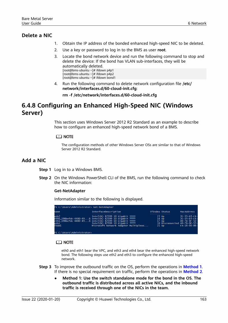
Delete a NIC1. Obtain the IP address of the bonded enhanced high-speed NIC to be deleted.2. Use a key or password to log in to the BMS as user root.3. Locate the bond network device and run the following command to stop and
delete the device: If the bond has VLAN sub-interfaces, they will beautomatically deleted.[root@bms-ubuntu ~]# ifdown p4p1[root@bms-ubuntu ~]# ifdown p4p2[root@bms-ubuntu ~]# ifdown bond1
4. Run the following command to delete network configuration file /etc/network/interfaces.d/60-cloud-init.cfg:rm -f /etc/network/interfaces.d/60-cloud-init.cfg
6.4.8 Configuring an Enhanced High-Speed NIC (WindowsServer)
This section uses Windows Server 2012 R2 Standard as an example to describehow to configure an enhanced high-speed network bond of a BMS.
The configuration methods of other Windows Server OSs are similar to that of WindowsServer 2012 R2 Standard.
Add a NIC
Step 1 Log in to a Windows BMS.
Step 2 On the Windows PowerShell CLI of the BMS, run the following command to checkthe NIC information:
Get-NetAdapter
Information similar to the following is displayed.
eth0 and eth1 bear the VPC, and eth3 and eth4 bear the enhanced high-speed networkbond. The following steps use eth2 and eth3 to configure the enhanced high-speednetwork.
Step 3 To improve the outbound traffic on the OS, perform the operations in Method 1.If there is no special requirement on traffic, perform the operations in Method 2.● Method 1: Use the switch standalone mode for the bond in the OS. The
outbound traffic is distributed across all active NICs, and the inboundtraffic is received through one of the NICs in the team.
Bare Metal ServerUser Guide 6 Network
Issue 22 (2020-01-20) Copyright © Huawei Technologies Co., Ltd. 163
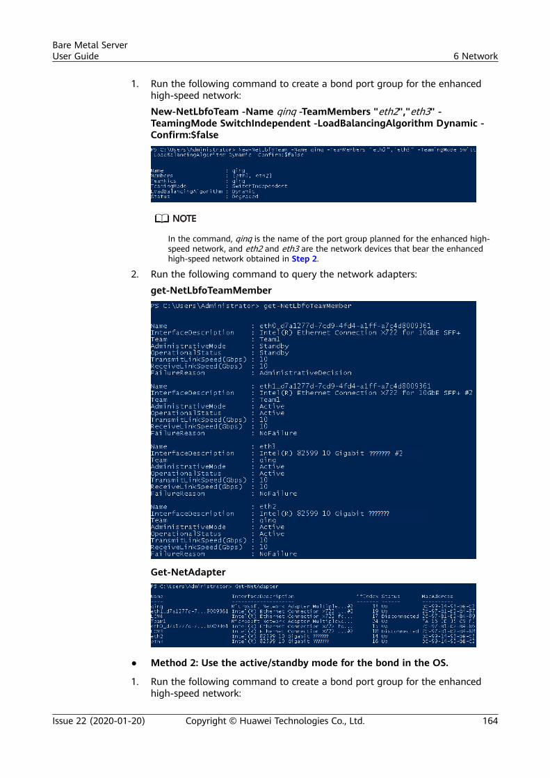
1. Run the following command to create a bond port group for the enhancedhigh-speed network:
New-NetLbfoTeam -Name qinq -TeamMembers "eth2","eth3" -TeamingMode SwitchIndependent -LoadBalancingAlgorithm Dynamic -Confirm:$false
In the command, qinq is the name of the port group planned for the enhanced high-speed network, and eth2 and eth3 are the network devices that bear the enhancedhigh-speed network obtained in Step 2.
2. Run the following command to query the network adapters:
get-NetLbfoTeamMember
Get-NetAdapter
● Method 2: Use the active/standby mode for the bond in the OS.
1. Run the following command to create a bond port group for the enhancedhigh-speed network:
Bare Metal ServerUser Guide 6 Network
Issue 22 (2020-01-20) Copyright © Huawei Technologies Co., Ltd. 164
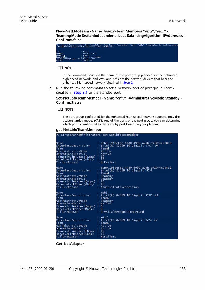
New-NetLbfoTeam -Name Team2 -TeamMembers "eth2","eth3" -TeamingMode SwitchIndependent -LoadBalancingAlgorithm IPAddresses -Confirm:$false
In the command, Team2 is the name of the port group planned for the enhancedhigh-speed network, and eth2 and eth3 are the network devices that bear theenhanced high-speed network obtained in Step 2.
2. Run the following command to set a network port of port group Team2created in Step 3.1 to the standby port:Set-NetLbfoTeamMember -Name "eth3" -AdministrativeMode Standby -Confirm:$false
The port group configured for the enhanced high-speed network supports only theactive/standby mode. eth3 is one of the ports of the port group. You can determinewhich port is configured as the standby port based on your planning.
get-NetLbfoTeamMember
Get-NetAdapter
Bare Metal ServerUser Guide 6 Network
Issue 22 (2020-01-20) Copyright © Huawei Technologies Co., Ltd. 165
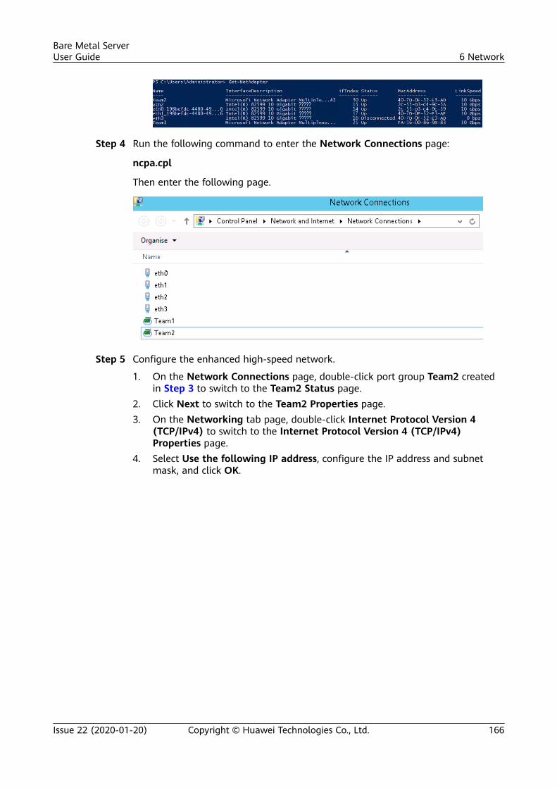
Step 4 Run the following command to enter the Network Connections page:
ncpa.cpl
Then enter the following page.
Step 5 Configure the enhanced high-speed network.
1. On the Network Connections page, double-click port group Team2 createdin Step 3 to switch to the Team2 Status page.
2. Click Next to switch to the Team2 Properties page.3. On the Networking tab page, double-click Internet Protocol Version 4
(TCP/IPv4) to switch to the Internet Protocol Version 4 (TCP/IPv4)Properties page.
4. Select Use the following IP address, configure the IP address and subnetmask, and click OK.
Bare Metal ServerUser Guide 6 Network
Issue 22 (2020-01-20) Copyright © Huawei Technologies Co., Ltd. 166
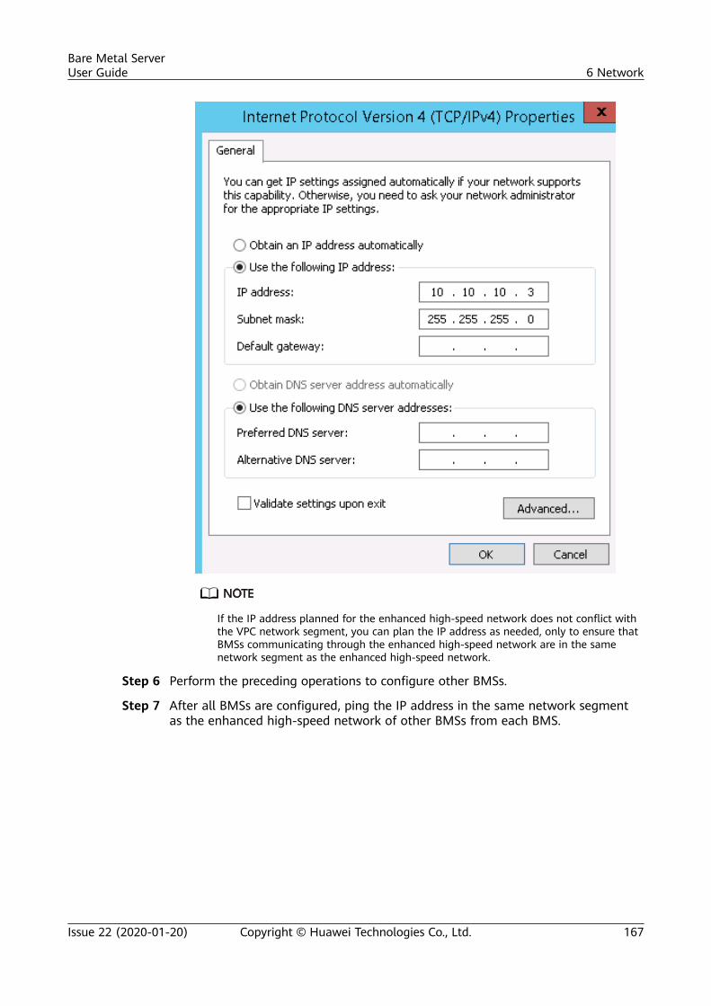
If the IP address planned for the enhanced high-speed network does not conflict withthe VPC network segment, you can plan the IP address as needed, only to ensure thatBMSs communicating through the enhanced high-speed network are in the samenetwork segment as the enhanced high-speed network.
Step 6 Perform the preceding operations to configure other BMSs.
Step 7 After all BMSs are configured, ping the IP address in the same network segmentas the enhanced high-speed network of other BMSs from each BMS.
Bare Metal ServerUser Guide 6 Network
Issue 22 (2020-01-20) Copyright © Huawei Technologies Co., Ltd. 167
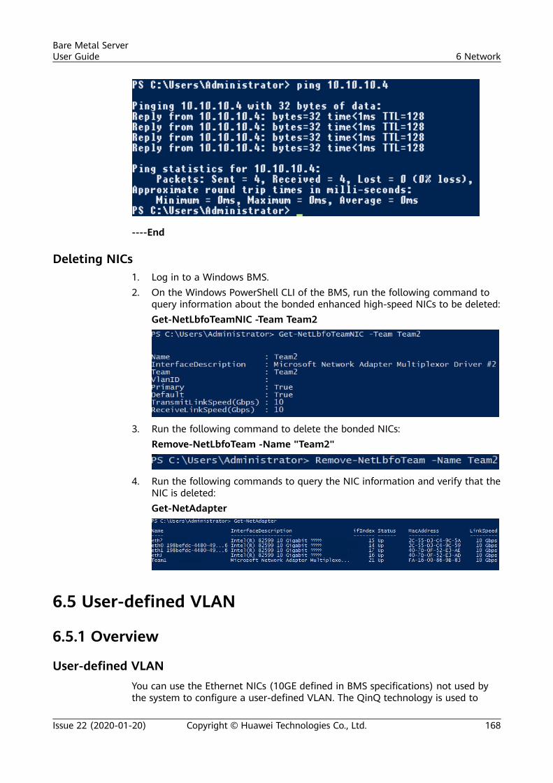
----End
Deleting NICs1. Log in to a Windows BMS.2. On the Windows PowerShell CLI of the BMS, run the following command to
query information about the bonded enhanced high-speed NICs to be deleted:Get-NetLbfoTeamNIC -Team Team2
3. Run the following command to delete the bonded NICs:Remove-NetLbfoTeam -Name "Team2"
4. Run the following commands to query the NIC information and verify that theNIC is deleted:Get-NetAdapter
6.5 User-defined VLAN
6.5.1 Overview
User-defined VLANYou can use the Ethernet NICs (10GE defined in BMS specifications) not used bythe system to configure a user-defined VLAN. The QinQ technology is used to
Bare Metal ServerUser Guide 6 Network
Issue 22 (2020-01-20) Copyright © Huawei Technologies Co., Ltd. 168
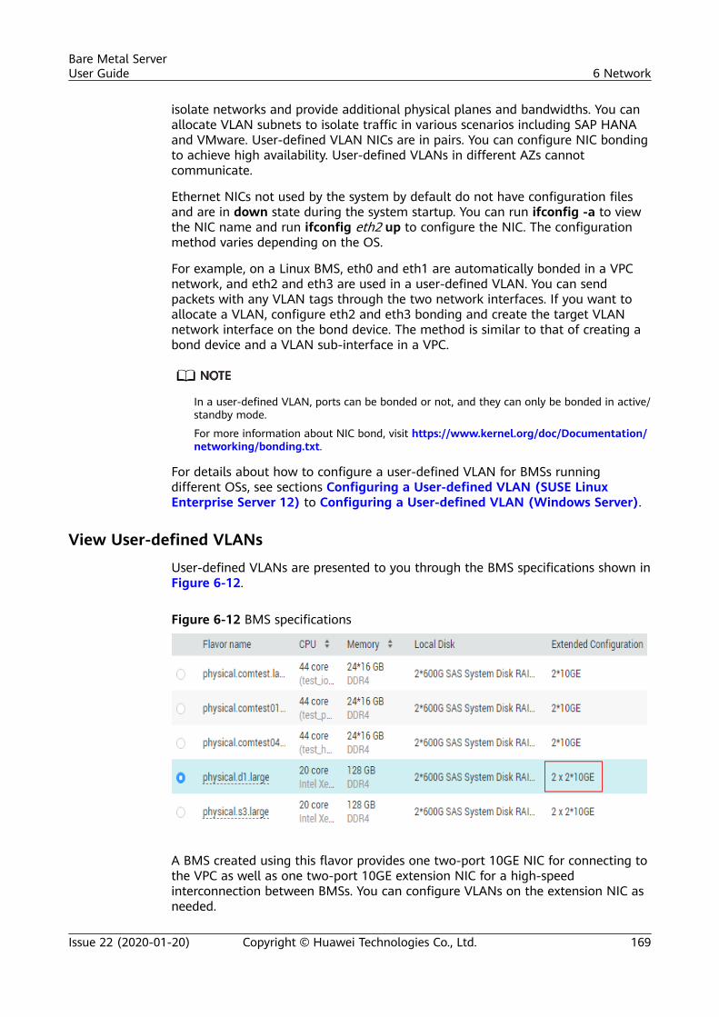
isolate networks and provide additional physical planes and bandwidths. You canallocate VLAN subnets to isolate traffic in various scenarios including SAP HANAand VMware. User-defined VLAN NICs are in pairs. You can configure NIC bondingto achieve high availability. User-defined VLANs in different AZs cannotcommunicate.
Ethernet NICs not used by the system by default do not have configuration filesand are in down state during the system startup. You can run ifconfig -a to viewthe NIC name and run ifconfig eth2 up to configure the NIC. The configurationmethod varies depending on the OS.
For example, on a Linux BMS, eth0 and eth1 are automatically bonded in a VPCnetwork, and eth2 and eth3 are used in a user-defined VLAN. You can sendpackets with any VLAN tags through the two network interfaces. If you want toallocate a VLAN, configure eth2 and eth3 bonding and create the target VLANnetwork interface on the bond device. The method is similar to that of creating abond device and a VLAN sub-interface in a VPC.
In a user-defined VLAN, ports can be bonded or not, and they can only be bonded in active/standby mode.
For more information about NIC bond, visit https://www.kernel.org/doc/Documentation/networking/bonding.txt.
For details about how to configure a user-defined VLAN for BMSs runningdifferent OSs, see sections Configuring a User-defined VLAN (SUSE LinuxEnterprise Server 12) to Configuring a User-defined VLAN (Windows Server).
View User-defined VLANs
User-defined VLANs are presented to you through the BMS specifications shown inFigure 6-12.
Figure 6-12 BMS specifications
A BMS created using this flavor provides one two-port 10GE NIC for connecting tothe VPC as well as one two-port 10GE extension NIC for a high-speedinterconnection between BMSs. You can configure VLANs on the extension NIC asneeded.
Bare Metal ServerUser Guide 6 Network
Issue 22 (2020-01-20) Copyright © Huawei Technologies Co., Ltd. 169
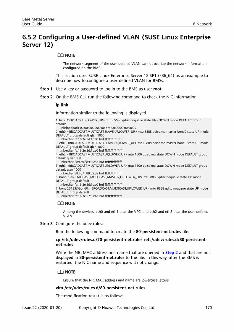
6.5.2 Configuring a User-defined VLAN (SUSE Linux EnterpriseServer 12)
The network segment of the user-defined VLAN cannot overlap the network informationconfigured on the BMS.
This section uses SUSE Linux Enterprise Server 12 SP1 (x86_64) as an example todescribe how to configure a user-defined VLAN for BMSs.
Step 1 Use a key or password to log in to the BMS as user root.
Step 2 On the BMS CLI, run the following command to check the NIC information:
ip link
Information similar to the following is displayed.
1: lo: <LOOPBACK,UP,LOWER_UP> mtu 65536 qdisc noqueue state UNKNOWN mode DEFAULT group default link/loopback 00:00:00:00:00:00 brd 00:00:00:00:00:002: eth0: <BROADCAST,MULTICAST,SLAVE,UP,LOWER_UP> mtu 8888 qdisc mq master bond0 state UP mode DEFAULT group default qlen 1000 link/ether fa:16:3e:3d:1c:e0 brd ff:ff:ff:ff:ff:ff3: eth1: <BROADCAST,MULTICAST,SLAVE,UP,LOWER_UP> mtu 8888 qdisc mq master bond0 state UP mode DEFAULT group default qlen 1000 link/ether fa:16:3e:3d:1c:e0 brd ff:ff:ff:ff:ff:ff4: eth2: <BROADCAST,MULTICAST,UP,LOWER_UP> mtu 1500 qdisc mq state DOWN mode DEFAULT group default qlen 1000 link/ether 38:4c:4f:89:55:8d brd ff:ff:ff:ff:ff:ff5: eth3: <BROADCAST,MULTICAST,UP,LOWER_UP> mtu 1500 qdisc mq state DOWN mode DEFAULT group default qlen 1000 link/ether 38:4c:4f:89:55:8e brd ff:ff:ff:ff:ff:ff6: bond0: <BROADCAST,MULTICAST,MASTER,UP,LOWER_UP> mtu 8888 qdisc noqueue state UP mode DEFAULT group default link/ether fa:16:3e:3d:1c:e0 brd ff:ff:ff:ff:ff:ff7: bond0.3133@bond0: <BROADCAST,MULTICAST,UP,LOWER_UP> mtu 8888 qdisc noqueue state UP mode DEFAULT group default link/ether fa:16:3e:57:87:6e brd ff:ff:ff:ff:ff:ff
Among the devices, eth0 and eth1 bear the VPC, and eth2 and eth3 bear the user-definedVLAN.
Step 3 Configure the udev rules:
Run the following command to create the 80-persistent-net.rules file:
cp /etc/udev/rules.d/70-persistent-net.rules /etc/udev/rules.d/80-persistent-net.rules
Write the NIC MAC address and name that are queried in Step 2 and that are notdisplayed in 80-persistent-net.rules to the file. In this way, after the BMS isrestarted, the NIC name and sequence will not change.
Ensure that the NIC MAC address and name are lowercase letters.
vim /etc/udev/rules.d/80-persistent-net.rules
The modification result is as follows:
Bare Metal ServerUser Guide 6 Network
Issue 22 (2020-01-20) Copyright © Huawei Technologies Co., Ltd. 170
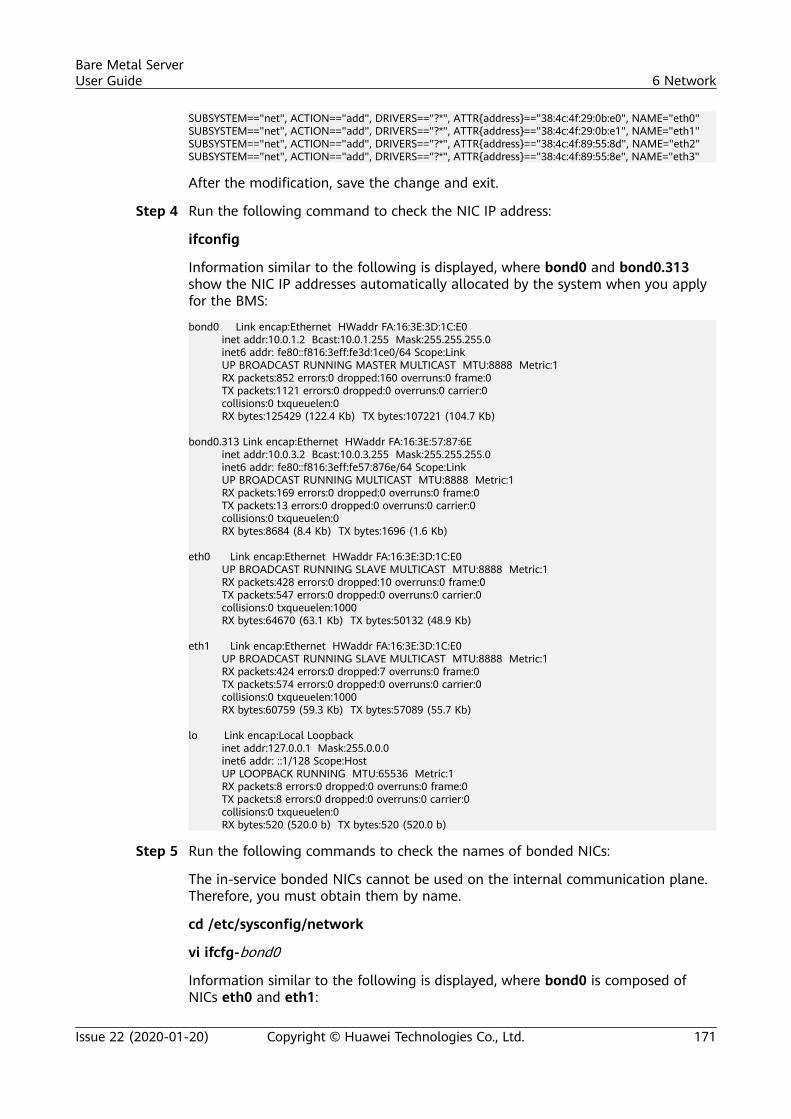
SUBSYSTEM=="net", ACTION=="add", DRIVERS=="?*", ATTR{address}=="38:4c:4f:29:0b:e0", NAME="eth0"SUBSYSTEM=="net", ACTION=="add", DRIVERS=="?*", ATTR{address}=="38:4c:4f:29:0b:e1", NAME="eth1"SUBSYSTEM=="net", ACTION=="add", DRIVERS=="?*", ATTR{address}=="38:4c:4f:89:55:8d", NAME="eth2"SUBSYSTEM=="net", ACTION=="add", DRIVERS=="?*", ATTR{address}=="38:4c:4f:89:55:8e", NAME="eth3"
After the modification, save the change and exit.
Step 4 Run the following command to check the NIC IP address:
ifconfig
Information similar to the following is displayed, where bond0 and bond0.313show the NIC IP addresses automatically allocated by the system when you applyfor the BMS:
bond0 Link encap:Ethernet HWaddr FA:16:3E:3D:1C:E0 inet addr:10.0.1.2 Bcast:10.0.1.255 Mask:255.255.255.0 inet6 addr: fe80::f816:3eff:fe3d:1ce0/64 Scope:Link UP BROADCAST RUNNING MASTER MULTICAST MTU:8888 Metric:1 RX packets:852 errors:0 dropped:160 overruns:0 frame:0 TX packets:1121 errors:0 dropped:0 overruns:0 carrier:0 collisions:0 txqueuelen:0 RX bytes:125429 (122.4 Kb) TX bytes:107221 (104.7 Kb)
bond0.313 Link encap:Ethernet HWaddr FA:16:3E:57:87:6E inet addr:10.0.3.2 Bcast:10.0.3.255 Mask:255.255.255.0 inet6 addr: fe80::f816:3eff:fe57:876e/64 Scope:Link UP BROADCAST RUNNING MULTICAST MTU:8888 Metric:1 RX packets:169 errors:0 dropped:0 overruns:0 frame:0 TX packets:13 errors:0 dropped:0 overruns:0 carrier:0 collisions:0 txqueuelen:0 RX bytes:8684 (8.4 Kb) TX bytes:1696 (1.6 Kb)
eth0 Link encap:Ethernet HWaddr FA:16:3E:3D:1C:E0 UP BROADCAST RUNNING SLAVE MULTICAST MTU:8888 Metric:1 RX packets:428 errors:0 dropped:10 overruns:0 frame:0 TX packets:547 errors:0 dropped:0 overruns:0 carrier:0 collisions:0 txqueuelen:1000 RX bytes:64670 (63.1 Kb) TX bytes:50132 (48.9 Kb)
eth1 Link encap:Ethernet HWaddr FA:16:3E:3D:1C:E0 UP BROADCAST RUNNING SLAVE MULTICAST MTU:8888 Metric:1 RX packets:424 errors:0 dropped:7 overruns:0 frame:0 TX packets:574 errors:0 dropped:0 overruns:0 carrier:0 collisions:0 txqueuelen:1000 RX bytes:60759 (59.3 Kb) TX bytes:57089 (55.7 Kb)
lo Link encap:Local Loopback inet addr:127.0.0.1 Mask:255.0.0.0 inet6 addr: ::1/128 Scope:Host UP LOOPBACK RUNNING MTU:65536 Metric:1 RX packets:8 errors:0 dropped:0 overruns:0 frame:0 TX packets:8 errors:0 dropped:0 overruns:0 carrier:0 collisions:0 txqueuelen:0 RX bytes:520 (520.0 b) TX bytes:520 (520.0 b)
Step 5 Run the following commands to check the names of bonded NICs:
The in-service bonded NICs cannot be used on the internal communication plane.Therefore, you must obtain them by name.
cd /etc/sysconfig/network
vi ifcfg-bond0
Information similar to the following is displayed, where bond0 is composed ofNICs eth0 and eth1:
Bare Metal ServerUser Guide 6 Network
Issue 22 (2020-01-20) Copyright © Huawei Technologies Co., Ltd. 171
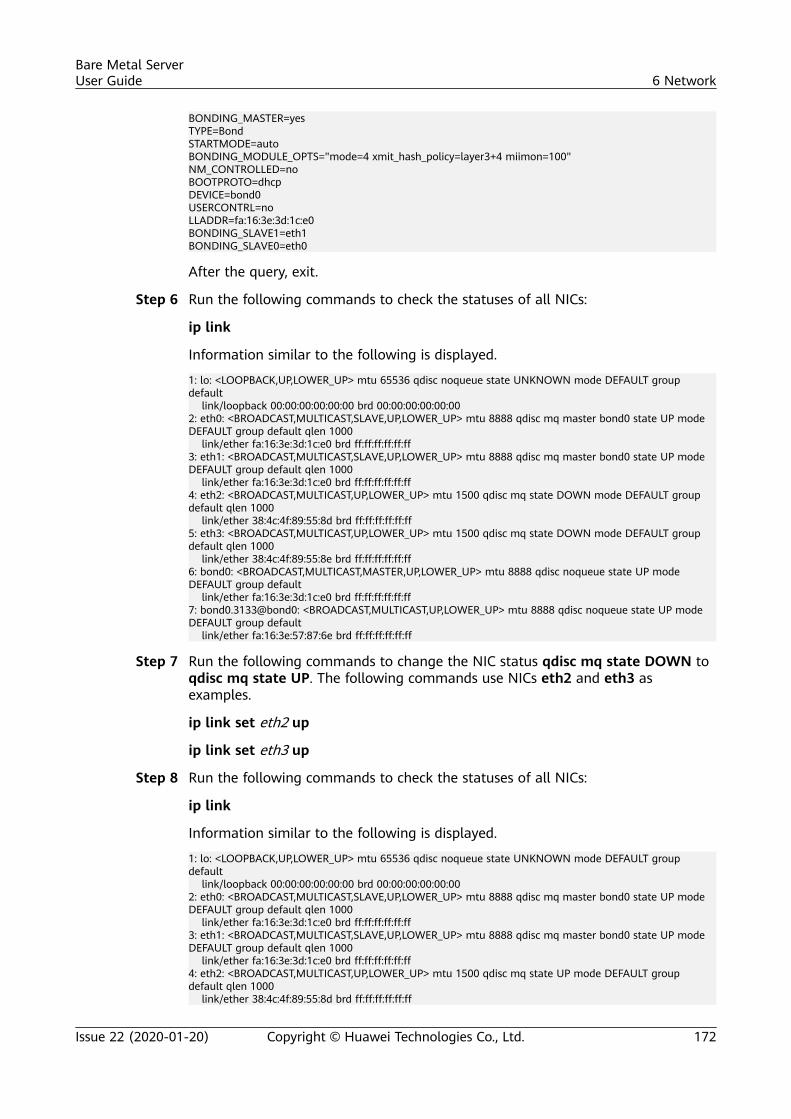
BONDING_MASTER=yesTYPE=BondSTARTMODE=autoBONDING_MODULE_OPTS="mode=4 xmit_hash_policy=layer3+4 miimon=100"NM_CONTROLLED=noBOOTPROTO=dhcpDEVICE=bond0USERCONTRL=noLLADDR=fa:16:3e:3d:1c:e0BONDING_SLAVE1=eth1BONDING_SLAVE0=eth0
After the query, exit.
Step 6 Run the following commands to check the statuses of all NICs:
ip link
Information similar to the following is displayed.
1: lo: <LOOPBACK,UP,LOWER_UP> mtu 65536 qdisc noqueue state UNKNOWN mode DEFAULT group default link/loopback 00:00:00:00:00:00 brd 00:00:00:00:00:002: eth0: <BROADCAST,MULTICAST,SLAVE,UP,LOWER_UP> mtu 8888 qdisc mq master bond0 state UP mode DEFAULT group default qlen 1000 link/ether fa:16:3e:3d:1c:e0 brd ff:ff:ff:ff:ff:ff3: eth1: <BROADCAST,MULTICAST,SLAVE,UP,LOWER_UP> mtu 8888 qdisc mq master bond0 state UP mode DEFAULT group default qlen 1000 link/ether fa:16:3e:3d:1c:e0 brd ff:ff:ff:ff:ff:ff4: eth2: <BROADCAST,MULTICAST,UP,LOWER_UP> mtu 1500 qdisc mq state DOWN mode DEFAULT group default qlen 1000 link/ether 38:4c:4f:89:55:8d brd ff:ff:ff:ff:ff:ff5: eth3: <BROADCAST,MULTICAST,UP,LOWER_UP> mtu 1500 qdisc mq state DOWN mode DEFAULT group default qlen 1000 link/ether 38:4c:4f:89:55:8e brd ff:ff:ff:ff:ff:ff6: bond0: <BROADCAST,MULTICAST,MASTER,UP,LOWER_UP> mtu 8888 qdisc noqueue state UP mode DEFAULT group default link/ether fa:16:3e:3d:1c:e0 brd ff:ff:ff:ff:ff:ff7: bond0.3133@bond0: <BROADCAST,MULTICAST,UP,LOWER_UP> mtu 8888 qdisc noqueue state UP mode DEFAULT group default link/ether fa:16:3e:57:87:6e brd ff:ff:ff:ff:ff:ff
Step 7 Run the following commands to change the NIC status qdisc mq state DOWN toqdisc mq state UP. The following commands use NICs eth2 and eth3 asexamples.
ip link set eth2 up
ip link set eth3 up
Step 8 Run the following commands to check the statuses of all NICs:
ip link
Information similar to the following is displayed.
1: lo: <LOOPBACK,UP,LOWER_UP> mtu 65536 qdisc noqueue state UNKNOWN mode DEFAULT group default link/loopback 00:00:00:00:00:00 brd 00:00:00:00:00:002: eth0: <BROADCAST,MULTICAST,SLAVE,UP,LOWER_UP> mtu 8888 qdisc mq master bond0 state UP mode DEFAULT group default qlen 1000 link/ether fa:16:3e:3d:1c:e0 brd ff:ff:ff:ff:ff:ff3: eth1: <BROADCAST,MULTICAST,SLAVE,UP,LOWER_UP> mtu 8888 qdisc mq master bond0 state UP mode DEFAULT group default qlen 1000 link/ether fa:16:3e:3d:1c:e0 brd ff:ff:ff:ff:ff:ff4: eth2: <BROADCAST,MULTICAST,UP,LOWER_UP> mtu 1500 qdisc mq state UP mode DEFAULT group default qlen 1000 link/ether 38:4c:4f:89:55:8d brd ff:ff:ff:ff:ff:ff
Bare Metal ServerUser Guide 6 Network
Issue 22 (2020-01-20) Copyright © Huawei Technologies Co., Ltd. 172
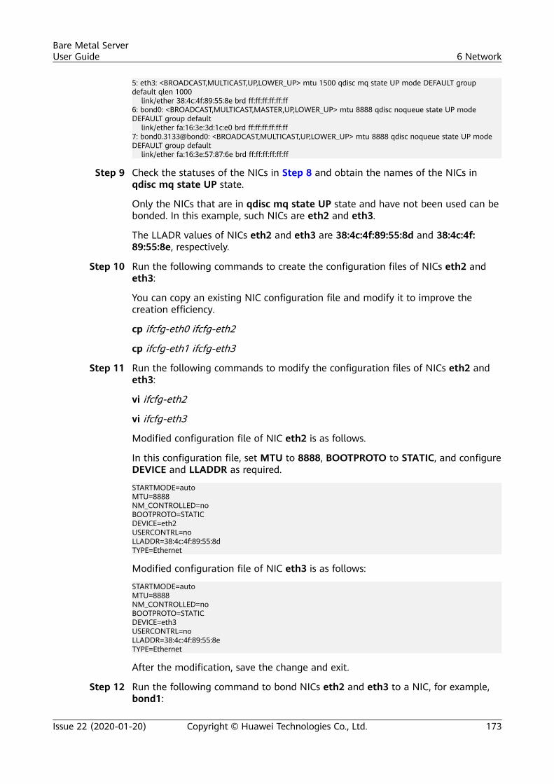
5: eth3: <BROADCAST,MULTICAST,UP,LOWER_UP> mtu 1500 qdisc mq state UP mode DEFAULT group default qlen 1000 link/ether 38:4c:4f:89:55:8e brd ff:ff:ff:ff:ff:ff6: bond0: <BROADCAST,MULTICAST,MASTER,UP,LOWER_UP> mtu 8888 qdisc noqueue state UP mode DEFAULT group default link/ether fa:16:3e:3d:1c:e0 brd ff:ff:ff:ff:ff:ff7: bond0.3133@bond0: <BROADCAST,MULTICAST,UP,LOWER_UP> mtu 8888 qdisc noqueue state UP mode DEFAULT group default link/ether fa:16:3e:57:87:6e brd ff:ff:ff:ff:ff:ff
Step 9 Check the statuses of the NICs in Step 8 and obtain the names of the NICs inqdisc mq state UP state.
Only the NICs that are in qdisc mq state UP state and have not been used can bebonded. In this example, such NICs are eth2 and eth3.
The LLADR values of NICs eth2 and eth3 are 38:4c:4f:89:55:8d and 38:4c:4f:89:55:8e, respectively.
Step 10 Run the following commands to create the configuration files of NICs eth2 andeth3:
You can copy an existing NIC configuration file and modify it to improve thecreation efficiency.
cp ifcfg-eth0 ifcfg-eth2
cp ifcfg-eth1 ifcfg-eth3
Step 11 Run the following commands to modify the configuration files of NICs eth2 andeth3:
vi ifcfg-eth2
vi ifcfg-eth3
Modified configuration file of NIC eth2 is as follows.
In this configuration file, set MTU to 8888, BOOTPROTO to STATIC, and configureDEVICE and LLADDR as required.
STARTMODE=autoMTU=8888NM_CONTROLLED=noBOOTPROTO=STATICDEVICE=eth2USERCONTRL=noLLADDR=38:4c:4f:89:55:8dTYPE=Ethernet
Modified configuration file of NIC eth3 is as follows:
STARTMODE=autoMTU=8888NM_CONTROLLED=noBOOTPROTO=STATICDEVICE=eth3USERCONTRL=noLLADDR=38:4c:4f:89:55:8eTYPE=Ethernet
After the modification, save the change and exit.
Step 12 Run the following command to bond NICs eth2 and eth3 to a NIC, for example,bond1:
Bare Metal ServerUser Guide 6 Network
Issue 22 (2020-01-20) Copyright © Huawei Technologies Co., Ltd. 173
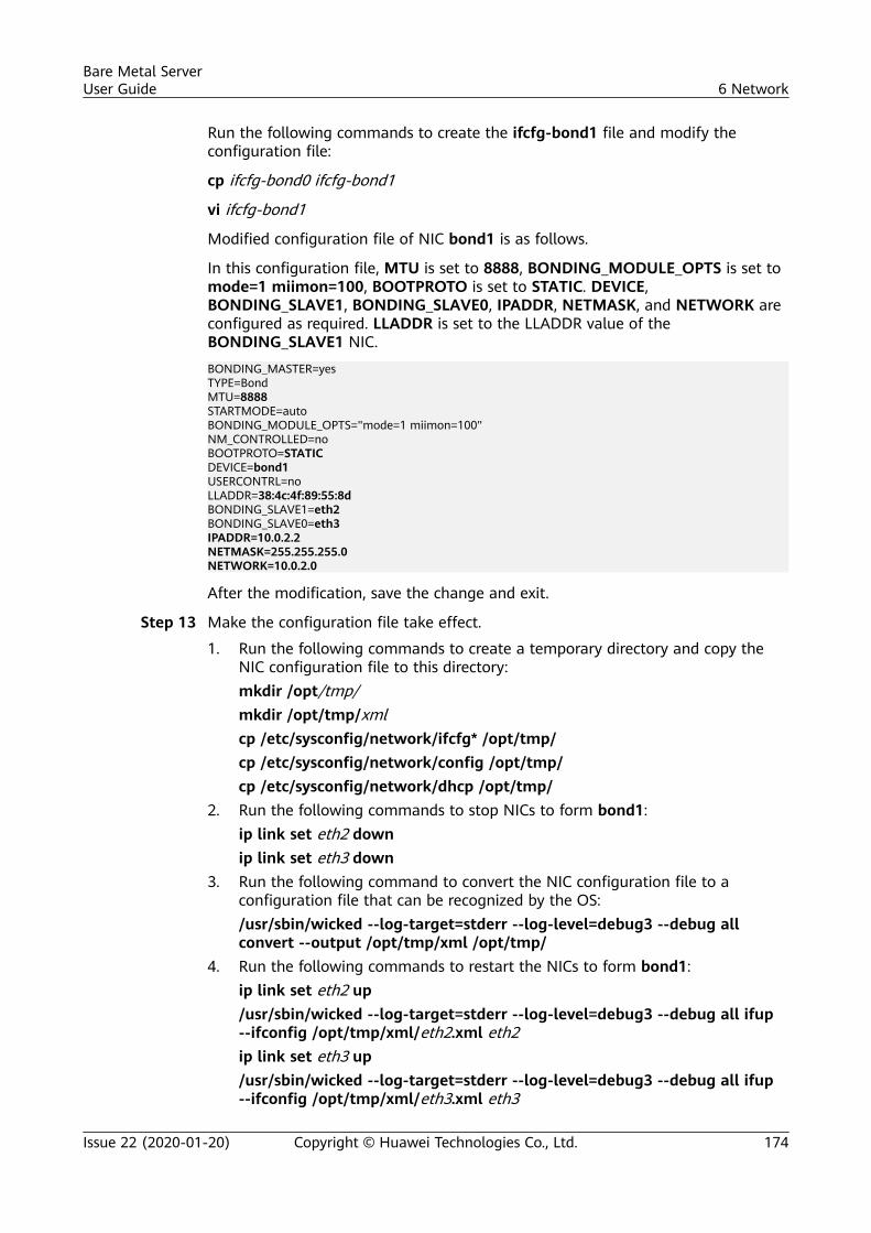
Run the following commands to create the ifcfg-bond1 file and modify theconfiguration file:
cp ifcfg-bond0 ifcfg-bond1
vi ifcfg-bond1
Modified configuration file of NIC bond1 is as follows.
In this configuration file, MTU is set to 8888, BONDING_MODULE_OPTS is set tomode=1 miimon=100, BOOTPROTO is set to STATIC. DEVICE,BONDING_SLAVE1, BONDING_SLAVE0, IPADDR, NETMASK, and NETWORK areconfigured as required. LLADDR is set to the LLADDR value of theBONDING_SLAVE1 NIC.
BONDING_MASTER=yesTYPE=BondMTU=8888STARTMODE=autoBONDING_MODULE_OPTS="mode=1 miimon=100"NM_CONTROLLED=noBOOTPROTO=STATICDEVICE=bond1USERCONTRL=noLLADDR=38:4c:4f:89:55:8dBONDING_SLAVE1=eth2BONDING_SLAVE0=eth3IPADDR=10.0.2.2NETMASK=255.255.255.0NETWORK=10.0.2.0
After the modification, save the change and exit.
Step 13 Make the configuration file take effect.
1. Run the following commands to create a temporary directory and copy theNIC configuration file to this directory:mkdir /opt/tmp/mkdir /opt/tmp/xmlcp /etc/sysconfig/network/ifcfg* /opt/tmp/cp /etc/sysconfig/network/config /opt/tmp/cp /etc/sysconfig/network/dhcp /opt/tmp/
2. Run the following commands to stop NICs to form bond1:ip link set eth2 downip link set eth3 down
3. Run the following command to convert the NIC configuration file to aconfiguration file that can be recognized by the OS:/usr/sbin/wicked --log-target=stderr --log-level=debug3 --debug allconvert --output /opt/tmp/xml /opt/tmp/
4. Run the following commands to restart the NICs to form bond1:ip link set eth2 up/usr/sbin/wicked --log-target=stderr --log-level=debug3 --debug all ifup--ifconfig /opt/tmp/xml/eth2.xml eth2ip link set eth3 up/usr/sbin/wicked --log-target=stderr --log-level=debug3 --debug all ifup--ifconfig /opt/tmp/xml/eth3.xml eth3
Bare Metal ServerUser Guide 6 Network
Issue 22 (2020-01-20) Copyright © Huawei Technologies Co., Ltd. 174
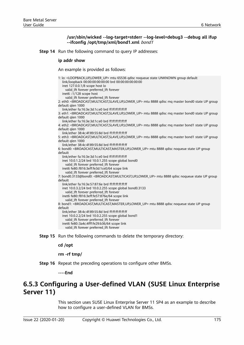
/usr/sbin/wicked --log-target=stderr --log-level=debug3 --debug all ifup--ifconfig /opt/tmp/xml/bond1.xml bond1
Step 14 Run the following command to query IP addresses:
ip addr show
An example is provided as follows:
1: lo: <LOOPBACK,UP,LOWER_UP> mtu 65536 qdisc noqueue state UNKNOWN group default link/loopback 00:00:00:00:00:00 brd 00:00:00:00:00:00 inet 127.0.0.1/8 scope host lo valid_lft forever preferred_lft forever inet6 ::1/128 scope host valid_lft forever preferred_lft forever2: eth0: <BROADCAST,MULTICAST,SLAVE,UP,LOWER_UP> mtu 8888 qdisc mq master bond0 state UP group default qlen 1000 link/ether fa:16:3e:3d:1c:e0 brd ff:ff:ff:ff:ff:ff3: eth1: <BROADCAST,MULTICAST,SLAVE,UP,LOWER_UP> mtu 8888 qdisc mq master bond0 state UP group default qlen 1000 link/ether fa:16:3e:3d:1c:e0 brd ff:ff:ff:ff:ff:ff4: eth2: <BROADCAST,MULTICAST,SLAVE,UP,LOWER_UP> mtu 8888 qdisc mq master bond1 state UP group default qlen 1000 link/ether 38:4c:4f:89:55:8d brd ff:ff:ff:ff:ff:ff5: eth3: <BROADCAST,MULTICAST,SLAVE,UP,LOWER_UP> mtu 8888 qdisc mq master bond1 state UP group default qlen 1000 link/ether 38:4c:4f:89:55:8d brd ff:ff:ff:ff:ff:ff6: bond0: <BROADCAST,MULTICAST,MASTER,UP,LOWER_UP> mtu 8888 qdisc noqueue state UP group default link/ether fa:16:3e:3d:1c:e0 brd ff:ff:ff:ff:ff:ff inet 10.0.1.2/24 brd 10.0.1.255 scope global bond0 valid_lft forever preferred_lft forever inet6 fe80::f816:3eff:fe3d:1ce0/64 scope link valid_lft forever preferred_lft forever7: bond0.3133@bond0: <BROADCAST,MULTICAST,UP,LOWER_UP> mtu 8888 qdisc noqueue state UP group default link/ether fa:16:3e:57:87:6e brd ff:ff:ff:ff:ff:ff inet 10.0.3.2/24 brd 10.0.2.255 scope global bond0.3133 valid_lft forever preferred_lft forever inet6 fe80::f816:3eff:fe57:876e/64 scope link valid_lft forever preferred_lft forever8: bond1: <BROADCAST,MULTICAST,MASTER,UP,LOWER_UP> mtu 8888 qdisc noqueue state UP group default link/ether 38:4c:4f:89:55:8d brd ff:ff:ff:ff:ff:ff inet 10.0.2.2/24 brd 10.0.2.255 scope global bond1 valid_lft forever preferred_lft forever inet6 fe80::3a4c:4fff:fe29:b36/64 scope link valid_lft forever preferred_lft forever
Step 15 Run the following commands to delete the temporary directory:
cd /opt
rm -rf tmp/
Step 16 Repeat the preceding operations to configure other BMSs.
----End
6.5.3 Configuring a User-defined VLAN (SUSE Linux EnterpriseServer 11)
This section uses SUSE Linux Enterprise Server 11 SP4 as an example to describehow to configure a user-defined VLAN for BMSs.
Bare Metal ServerUser Guide 6 Network
Issue 22 (2020-01-20) Copyright © Huawei Technologies Co., Ltd. 175
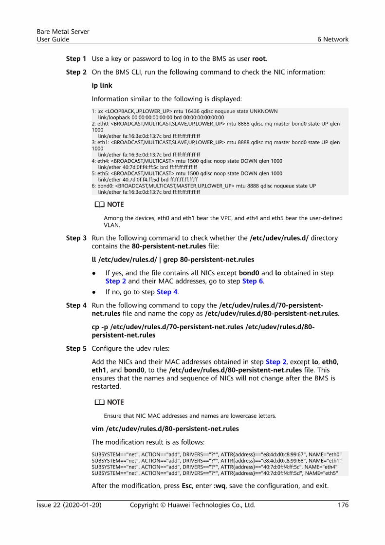
Step 1 Use a key or password to log in to the BMS as user root.
Step 2 On the BMS CLI, run the following command to check the NIC information:
ip link
Information similar to the following is displayed:
1: lo: <LOOPBACK,UP,LOWER_UP> mtu 16436 qdisc noqueue state UNKNOWN link/loopback 00:00:00:00:00:00 brd 00:00:00:00:00:002: eth0: <BROADCAST,MULTICAST,SLAVE,UP,LOWER_UP> mtu 8888 qdisc mq master bond0 state UP qlen 1000 link/ether fa:16:3e:0d:13:7c brd ff:ff:ff:ff:ff:ff3: eth1: <BROADCAST,MULTICAST,SLAVE,UP,LOWER_UP> mtu 8888 qdisc mq master bond0 state UP qlen 1000 link/ether fa:16:3e:0d:13:7c brd ff:ff:ff:ff:ff:ff4: eth4: <BROADCAST,MULTICAST> mtu 1500 qdisc noop state DOWN qlen 1000 link/ether 40:7d:0f:f4:ff:5c brd ff:ff:ff:ff:ff:ff5: eth5: <BROADCAST,MULTICAST> mtu 1500 qdisc noop state DOWN qlen 1000 link/ether 40:7d:0f:f4:ff:5d brd ff:ff:ff:ff:ff:ff6: bond0: <BROADCAST,MULTICAST,MASTER,UP,LOWER_UP> mtu 8888 qdisc noqueue state UP link/ether fa:16:3e:0d:13:7c brd ff:ff:ff:ff:ff:ff
Among the devices, eth0 and eth1 bear the VPC, and eth4 and eth5 bear the user-definedVLAN.
Step 3 Run the following command to check whether the /etc/udev/rules.d/ directorycontains the 80-persistent-net.rules file:
ll /etc/udev/rules.d/ | grep 80-persistent-net.rules
● If yes, and the file contains all NICs except bond0 and lo obtained in stepStep 2 and their MAC addresses, go to step Step 6.
● If no, go to step Step 4.
Step 4 Run the following command to copy the /etc/udev/rules.d/70-persistent-net.rules file and name the copy as /etc/udev/rules.d/80-persistent-net.rules.
cp -p /etc/udev/rules.d/70-persistent-net.rules /etc/udev/rules.d/80-persistent-net.rules
Step 5 Configure the udev rules:
Add the NICs and their MAC addresses obtained in step Step 2, except lo, eth0,eth1, and bond0, to the /etc/udev/rules.d/80-persistent-net.rules file. Thisensures that the names and sequence of NICs will not change after the BMS isrestarted.
Ensure that NIC MAC addresses and names are lowercase letters.
vim /etc/udev/rules.d/80-persistent-net.rules
The modification result is as follows:
SUBSYSTEM=="net", ACTION=="add", DRIVERS=="?*", ATTR{address}=="e8:4d:d0:c8:99:67", NAME="eth0"SUBSYSTEM=="net", ACTION=="add", DRIVERS=="?*", ATTR{address}=="e8:4d:d0:c8:99:68", NAME="eth1"SUBSYSTEM=="net", ACTION=="add", DRIVERS=="?*", ATTR{address}=="40:7d:0f:f4:ff:5c", NAME="eth4"SUBSYSTEM=="net", ACTION=="add", DRIVERS=="?*", ATTR{address}=="40:7d:0f:f4:ff:5d", NAME="eth5"
After the modification, press Esc, enter :wq, save the configuration, and exit.
Bare Metal ServerUser Guide 6 Network
Issue 22 (2020-01-20) Copyright © Huawei Technologies Co., Ltd. 176
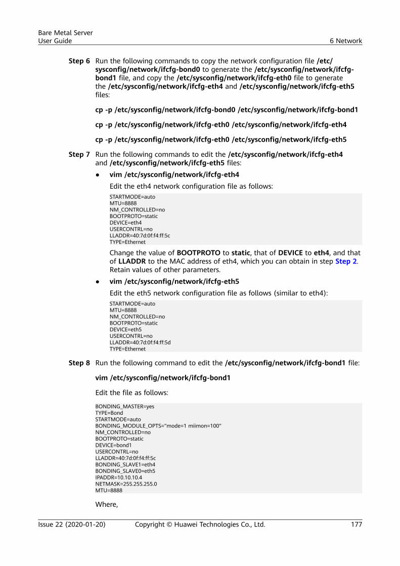
Step 6 Run the following commands to copy the network configuration file /etc/sysconfig/network/ifcfg-bond0 to generate the /etc/sysconfig/network/ifcfg-bond1 file, and copy the /etc/sysconfig/network/ifcfg-eth0 file to generatethe /etc/sysconfig/network/ifcfg-eth4 and /etc/sysconfig/network/ifcfg-eth5files:
cp -p /etc/sysconfig/network/ifcfg-bond0 /etc/sysconfig/network/ifcfg-bond1
cp -p /etc/sysconfig/network/ifcfg-eth0 /etc/sysconfig/network/ifcfg-eth4
cp -p /etc/sysconfig/network/ifcfg-eth0 /etc/sysconfig/network/ifcfg-eth5
Step 7 Run the following commands to edit the /etc/sysconfig/network/ifcfg-eth4and /etc/sysconfig/network/ifcfg-eth5 files:● vim /etc/sysconfig/network/ifcfg-eth4
Edit the eth4 network configuration file as follows:STARTMODE=autoMTU=8888NM_CONTROLLED=noBOOTPROTO=staticDEVICE=eth4USERCONTRL=noLLADDR=40:7d:0f:f4:ff:5cTYPE=Ethernet
Change the value of BOOTPROTO to static, that of DEVICE to eth4, and thatof LLADDR to the MAC address of eth4, which you can obtain in step Step 2.Retain values of other parameters.
● vim /etc/sysconfig/network/ifcfg-eth5Edit the eth5 network configuration file as follows (similar to eth4):STARTMODE=autoMTU=8888NM_CONTROLLED=noBOOTPROTO=staticDEVICE=eth5USERCONTRL=noLLADDR=40:7d:0f:f4:ff:5dTYPE=Ethernet
Step 8 Run the following command to edit the /etc/sysconfig/network/ifcfg-bond1 file:
vim /etc/sysconfig/network/ifcfg-bond1
Edit the file as follows:
BONDING_MASTER=yesTYPE=BondSTARTMODE=autoBONDING_MODULE_OPTS="mode=1 miimon=100"NM_CONTROLLED=noBOOTPROTO=staticDEVICE=bond1USERCONTRL=noLLADDR=40:7d:0f:f4:ff:5cBONDING_SLAVE1=eth4BONDING_SLAVE0=eth5IPADDR=10.10.10.4NETMASK=255.255.255.0MTU=8888
Where,
Bare Metal ServerUser Guide 6 Network
Issue 22 (2020-01-20) Copyright © Huawei Technologies Co., Ltd. 177
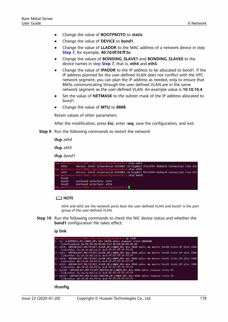
● Change the value of BOOTPROTO to static.● Change the value of DEVICE to bond1.● Change the value of LLADDR to the MAC address of a network device in step
Step 7, for example, 40:7d:0f:f4:ff:5c.● Change the values of BONDING_SLAVE1 and BONDING_SLAVE0 to the
device names in step Step 7, that is, eth4 and eth5.● Change the value of IPADDR to the IP address to be allocated to bond1. If the
IP address planned for the user-defined VLAN does not conflict with the VPCnetwork segment, you can plan the IP address as needed, only to ensure thatBMSs communicating through the user-defined VLAN are in the samenetwork segment as the user-defined VLAN. An example value is 10.10.10.4.
● Set the value of NETMASK to the subnet mask of the IP address allocated tobond1.
● Change the value of MTU to 8888.
Retain values of other parameters.
After the modification, press Esc, enter :wq, save the configuration, and exit.
Step 9 Run the following commands to restart the network:
ifup eth4
ifup eth5
ifup bond1
eth4 and eth5 are the network ports bear the user-defined VLAN and bond1 is the portgroup of the user-defined VLAN.
Step 10 Run the following commands to check the NIC device status and whether thebond1 configuration file takes effect:
ip link
ifconfig
Bare Metal ServerUser Guide 6 Network
Issue 22 (2020-01-20) Copyright © Huawei Technologies Co., Ltd. 178
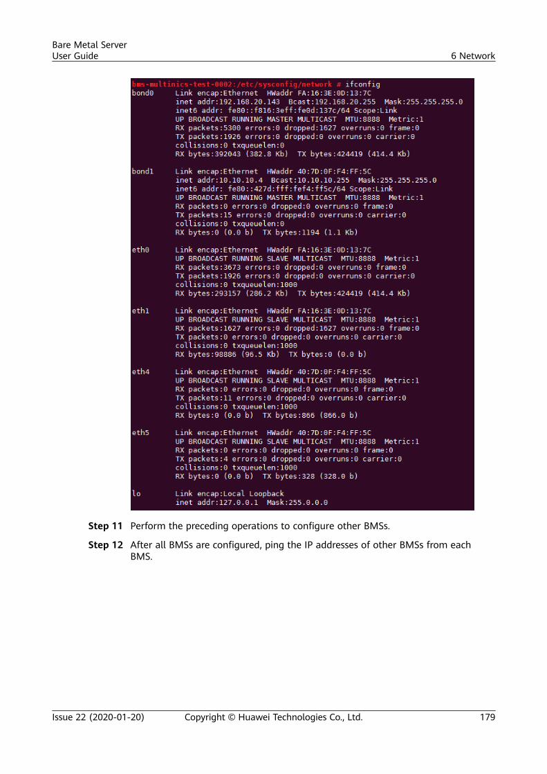
Step 11 Perform the preceding operations to configure other BMSs.
Step 12 After all BMSs are configured, ping the IP addresses of other BMSs from eachBMS.
Bare Metal ServerUser Guide 6 Network
Issue 22 (2020-01-20) Copyright © Huawei Technologies Co., Ltd. 179
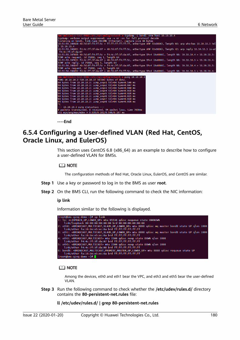
----End
6.5.4 Configuring a User-defined VLAN (Red Hat, CentOS,Oracle Linux, and EulerOS)
This section uses CentOS 6.8 (x86_64) as an example to describe how to configurea user-defined VLAN for BMSs.
The configuration methods of Red Hat, Oracle Linux, EulerOS, and CentOS are similar.
Step 1 Use a key or password to log in to the BMS as user root.
Step 2 On the BMS CLI, run the following command to check the NIC information:
ip link
Information similar to the following is displayed.
Among the devices, eth0 and eth1 bear the VPC, and eth3 and eth5 bear the user-definedVLAN.
Step 3 Run the following command to check whether the /etc/udev/rules.d/ directorycontains the 80-persistent-net.rules file:
ll /etc/udev/rules.d/ | grep 80-persistent-net.rules
Bare Metal ServerUser Guide 6 Network
Issue 22 (2020-01-20) Copyright © Huawei Technologies Co., Ltd. 180
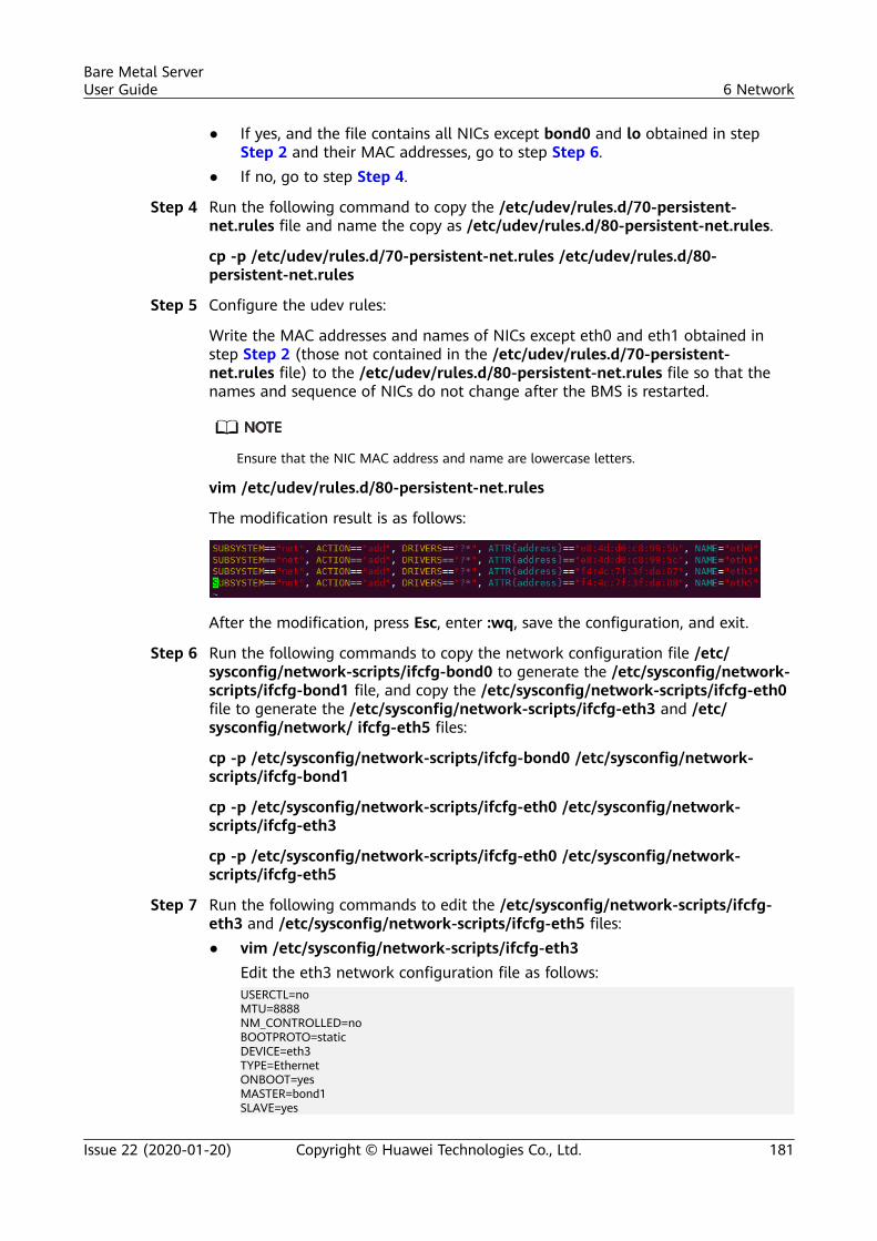
● If yes, and the file contains all NICs except bond0 and lo obtained in stepStep 2 and their MAC addresses, go to step Step 6.
● If no, go to step Step 4.
Step 4 Run the following command to copy the /etc/udev/rules.d/70-persistent-net.rules file and name the copy as /etc/udev/rules.d/80-persistent-net.rules.
cp -p /etc/udev/rules.d/70-persistent-net.rules /etc/udev/rules.d/80-persistent-net.rules
Step 5 Configure the udev rules:
Write the MAC addresses and names of NICs except eth0 and eth1 obtained instep Step 2 (those not contained in the /etc/udev/rules.d/70-persistent-net.rules file) to the /etc/udev/rules.d/80-persistent-net.rules file so that thenames and sequence of NICs do not change after the BMS is restarted.
Ensure that the NIC MAC address and name are lowercase letters.
vim /etc/udev/rules.d/80-persistent-net.rules
The modification result is as follows:
After the modification, press Esc, enter :wq, save the configuration, and exit.
Step 6 Run the following commands to copy the network configuration file /etc/sysconfig/network-scripts/ifcfg-bond0 to generate the /etc/sysconfig/network-scripts/ifcfg-bond1 file, and copy the /etc/sysconfig/network-scripts/ifcfg-eth0file to generate the /etc/sysconfig/network-scripts/ifcfg-eth3 and /etc/sysconfig/network/ ifcfg-eth5 files:
cp -p /etc/sysconfig/network-scripts/ifcfg-bond0 /etc/sysconfig/network-scripts/ifcfg-bond1
cp -p /etc/sysconfig/network-scripts/ifcfg-eth0 /etc/sysconfig/network-scripts/ifcfg-eth3
cp -p /etc/sysconfig/network-scripts/ifcfg-eth0 /etc/sysconfig/network-scripts/ifcfg-eth5
Step 7 Run the following commands to edit the /etc/sysconfig/network-scripts/ifcfg-eth3 and /etc/sysconfig/network-scripts/ifcfg-eth5 files:● vim /etc/sysconfig/network-scripts/ifcfg-eth3
Edit the eth3 network configuration file as follows:USERCTL=noMTU=8888NM_CONTROLLED=noBOOTPROTO=staticDEVICE=eth3TYPE=EthernetONBOOT=yesMASTER=bond1SLAVE=yes
Bare Metal ServerUser Guide 6 Network
Issue 22 (2020-01-20) Copyright © Huawei Technologies Co., Ltd. 181
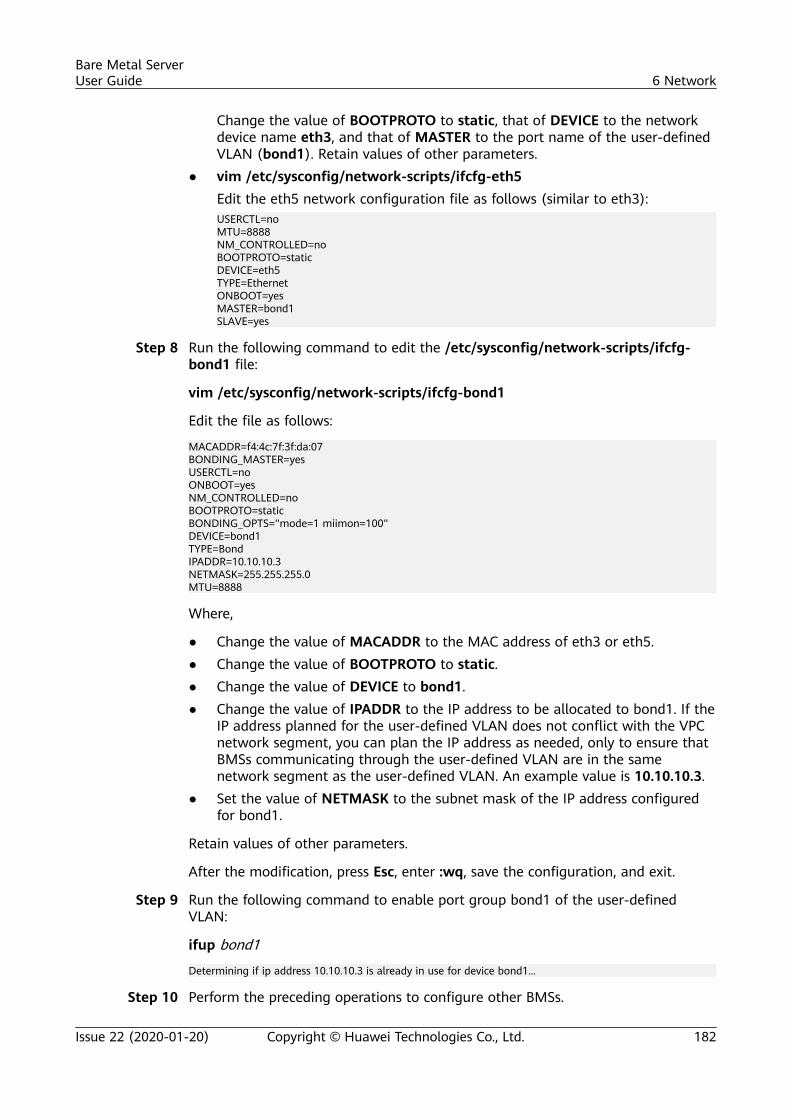
Change the value of BOOTPROTO to static, that of DEVICE to the networkdevice name eth3, and that of MASTER to the port name of the user-definedVLAN (bond1). Retain values of other parameters.
● vim /etc/sysconfig/network-scripts/ifcfg-eth5Edit the eth5 network configuration file as follows (similar to eth3):USERCTL=noMTU=8888NM_CONTROLLED=noBOOTPROTO=staticDEVICE=eth5TYPE=EthernetONBOOT=yesMASTER=bond1SLAVE=yes
Step 8 Run the following command to edit the /etc/sysconfig/network-scripts/ifcfg-bond1 file:
vim /etc/sysconfig/network-scripts/ifcfg-bond1
Edit the file as follows:
MACADDR=f4:4c:7f:3f:da:07BONDING_MASTER=yesUSERCTL=noONBOOT=yesNM_CONTROLLED=noBOOTPROTO=staticBONDING_OPTS="mode=1 miimon=100"DEVICE=bond1TYPE=BondIPADDR=10.10.10.3NETMASK=255.255.255.0MTU=8888
Where,
● Change the value of MACADDR to the MAC address of eth3 or eth5.● Change the value of BOOTPROTO to static.● Change the value of DEVICE to bond1.● Change the value of IPADDR to the IP address to be allocated to bond1. If the
IP address planned for the user-defined VLAN does not conflict with the VPCnetwork segment, you can plan the IP address as needed, only to ensure thatBMSs communicating through the user-defined VLAN are in the samenetwork segment as the user-defined VLAN. An example value is 10.10.10.3.
● Set the value of NETMASK to the subnet mask of the IP address configuredfor bond1.
Retain values of other parameters.
After the modification, press Esc, enter :wq, save the configuration, and exit.
Step 9 Run the following command to enable port group bond1 of the user-definedVLAN:
ifup bond1
Determining if ip address 10.10.10.3 is already in use for device bond1...
Step 10 Perform the preceding operations to configure other BMSs.
Bare Metal ServerUser Guide 6 Network
Issue 22 (2020-01-20) Copyright © Huawei Technologies Co., Ltd. 182
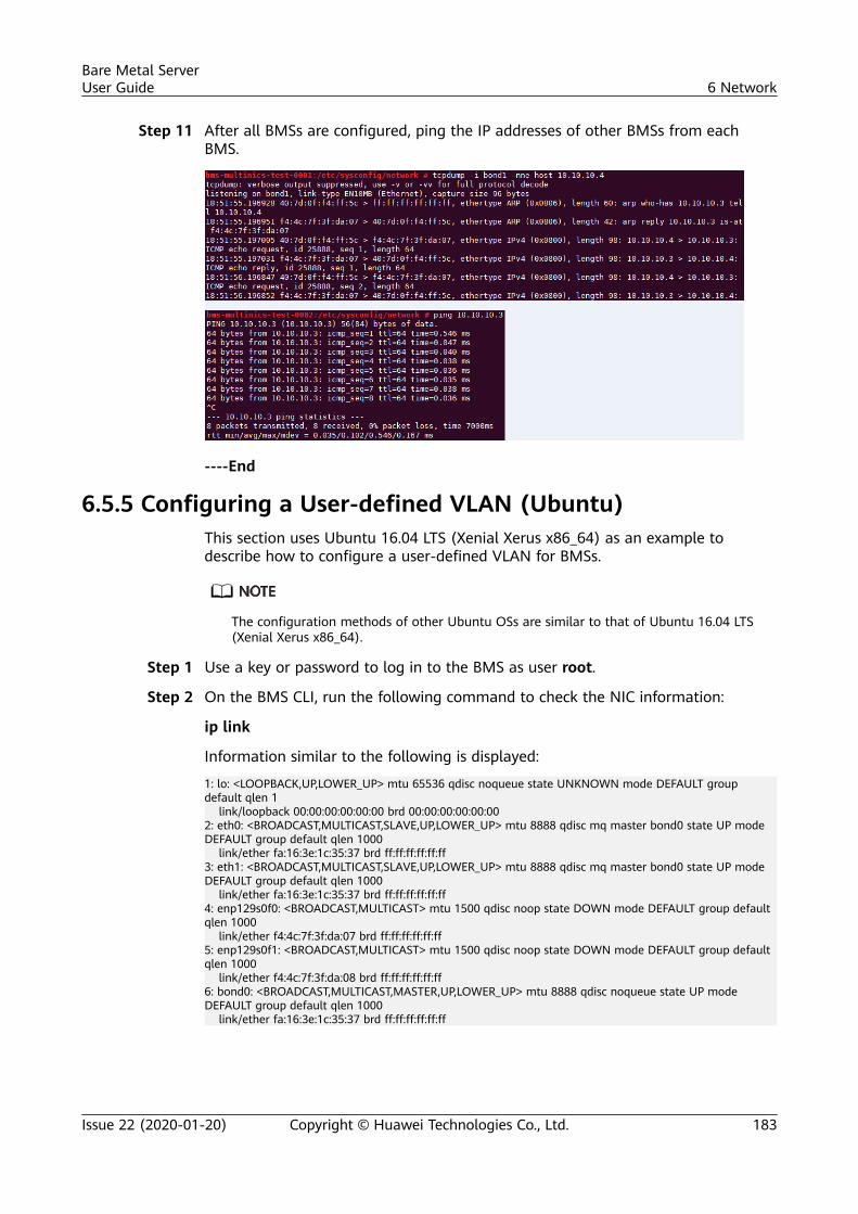
Step 11 After all BMSs are configured, ping the IP addresses of other BMSs from eachBMS.
----End
6.5.5 Configuring a User-defined VLAN (Ubuntu)This section uses Ubuntu 16.04 LTS (Xenial Xerus x86_64) as an example todescribe how to configure a user-defined VLAN for BMSs.
The configuration methods of other Ubuntu OSs are similar to that of Ubuntu 16.04 LTS(Xenial Xerus x86_64).
Step 1 Use a key or password to log in to the BMS as user root.
Step 2 On the BMS CLI, run the following command to check the NIC information:
ip link
Information similar to the following is displayed:
1: lo: <LOOPBACK,UP,LOWER_UP> mtu 65536 qdisc noqueue state UNKNOWN mode DEFAULT group default qlen 1 link/loopback 00:00:00:00:00:00 brd 00:00:00:00:00:002: eth0: <BROADCAST,MULTICAST,SLAVE,UP,LOWER_UP> mtu 8888 qdisc mq master bond0 state UP mode DEFAULT group default qlen 1000 link/ether fa:16:3e:1c:35:37 brd ff:ff:ff:ff:ff:ff3: eth1: <BROADCAST,MULTICAST,SLAVE,UP,LOWER_UP> mtu 8888 qdisc mq master bond0 state UP mode DEFAULT group default qlen 1000 link/ether fa:16:3e:1c:35:37 brd ff:ff:ff:ff:ff:ff4: enp129s0f0: <BROADCAST,MULTICAST> mtu 1500 qdisc noop state DOWN mode DEFAULT group default qlen 1000 link/ether f4:4c:7f:3f:da:07 brd ff:ff:ff:ff:ff:ff5: enp129s0f1: <BROADCAST,MULTICAST> mtu 1500 qdisc noop state DOWN mode DEFAULT group default qlen 1000 link/ether f4:4c:7f:3f:da:08 brd ff:ff:ff:ff:ff:ff6: bond0: <BROADCAST,MULTICAST,MASTER,UP,LOWER_UP> mtu 8888 qdisc noqueue state UP mode DEFAULT group default qlen 1000 link/ether fa:16:3e:1c:35:37 brd ff:ff:ff:ff:ff:ff
Bare Metal ServerUser Guide 6 Network
Issue 22 (2020-01-20) Copyright © Huawei Technologies Co., Ltd. 183
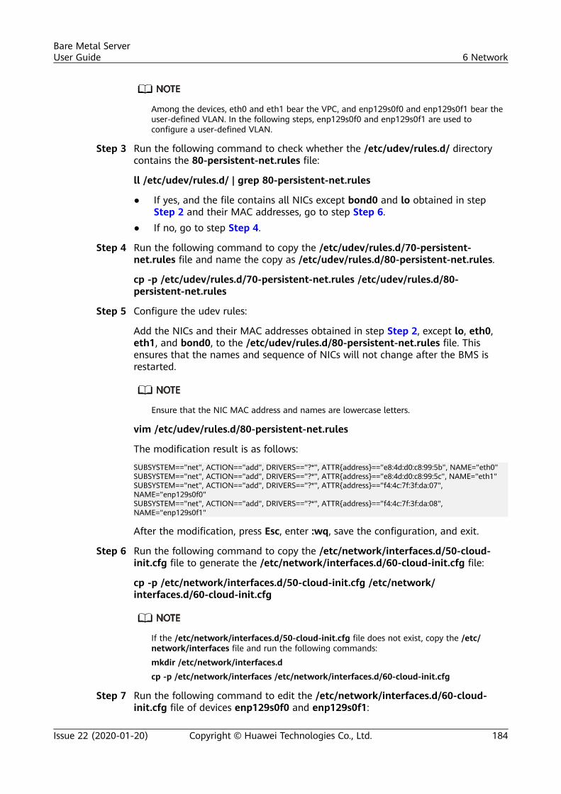
Among the devices, eth0 and eth1 bear the VPC, and enp129s0f0 and enp129s0f1 bear theuser-defined VLAN. In the following steps, enp129s0f0 and enp129s0f1 are used toconfigure a user-defined VLAN.
Step 3 Run the following command to check whether the /etc/udev/rules.d/ directorycontains the 80-persistent-net.rules file:
ll /etc/udev/rules.d/ | grep 80-persistent-net.rules
● If yes, and the file contains all NICs except bond0 and lo obtained in stepStep 2 and their MAC addresses, go to step Step 6.
● If no, go to step Step 4.
Step 4 Run the following command to copy the /etc/udev/rules.d/70-persistent-net.rules file and name the copy as /etc/udev/rules.d/80-persistent-net.rules.
cp -p /etc/udev/rules.d/70-persistent-net.rules /etc/udev/rules.d/80-persistent-net.rules
Step 5 Configure the udev rules:
Add the NICs and their MAC addresses obtained in step Step 2, except lo, eth0,eth1, and bond0, to the /etc/udev/rules.d/80-persistent-net.rules file. Thisensures that the names and sequence of NICs will not change after the BMS isrestarted.
Ensure that the NIC MAC address and names are lowercase letters.
vim /etc/udev/rules.d/80-persistent-net.rules
The modification result is as follows:
SUBSYSTEM=="net", ACTION=="add", DRIVERS=="?*", ATTR{address}=="e8:4d:d0:c8:99:5b", NAME="eth0"SUBSYSTEM=="net", ACTION=="add", DRIVERS=="?*", ATTR{address}=="e8:4d:d0:c8:99:5c", NAME="eth1"SUBSYSTEM=="net", ACTION=="add", DRIVERS=="?*", ATTR{address}=="f4:4c:7f:3f:da:07", NAME="enp129s0f0"SUBSYSTEM=="net", ACTION=="add", DRIVERS=="?*", ATTR{address}=="f4:4c:7f:3f:da:08", NAME="enp129s0f1"
After the modification, press Esc, enter :wq, save the configuration, and exit.
Step 6 Run the following command to copy the /etc/network/interfaces.d/50-cloud-init.cfg file to generate the /etc/network/interfaces.d/60-cloud-init.cfg file:
cp -p /etc/network/interfaces.d/50-cloud-init.cfg /etc/network/interfaces.d/60-cloud-init.cfg
If the /etc/network/interfaces.d/50-cloud-init.cfg file does not exist, copy the /etc/network/interfaces file and run the following commands:
mkdir /etc/network/interfaces.d
cp -p /etc/network/interfaces /etc/network/interfaces.d/60-cloud-init.cfg
Step 7 Run the following command to edit the /etc/network/interfaces.d/60-cloud-init.cfg file of devices enp129s0f0 and enp129s0f1:
Bare Metal ServerUser Guide 6 Network
Issue 22 (2020-01-20) Copyright © Huawei Technologies Co., Ltd. 184
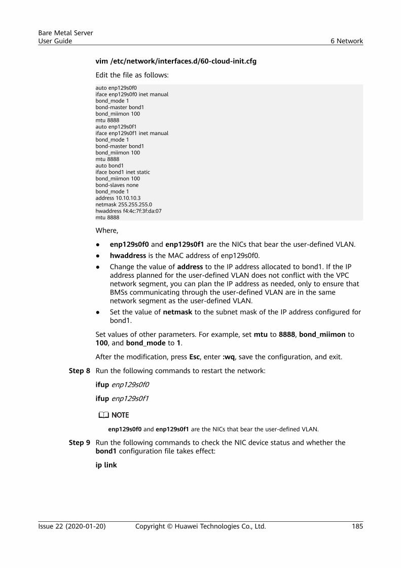
vim /etc/network/interfaces.d/60-cloud-init.cfg
Edit the file as follows:
auto enp129s0f0iface enp129s0f0 inet manualbond_mode 1bond-master bond1bond_miimon 100mtu 8888auto enp129s0f1iface enp129s0f1 inet manualbond_mode 1bond-master bond1bond_miimon 100mtu 8888auto bond1iface bond1 inet staticbond_miimon 100bond-slaves nonebond_mode 1address 10.10.10.3netmask 255.255.255.0hwaddress f4:4c:7f:3f:da:07mtu 8888
Where,
● enp129s0f0 and enp129s0f1 are the NICs that bear the user-defined VLAN.● hwaddress is the MAC address of enp129s0f0.● Change the value of address to the IP address allocated to bond1. If the IP
address planned for the user-defined VLAN does not conflict with the VPCnetwork segment, you can plan the IP address as needed, only to ensure thatBMSs communicating through the user-defined VLAN are in the samenetwork segment as the user-defined VLAN.
● Set the value of netmask to the subnet mask of the IP address configured forbond1.
Set values of other parameters. For example, set mtu to 8888, bond_miimon to100, and bond_mode to 1.
After the modification, press Esc, enter :wq, save the configuration, and exit.
Step 8 Run the following commands to restart the network:
ifup enp129s0f0
ifup enp129s0f1
enp129s0f0 and enp129s0f1 are the NICs that bear the user-defined VLAN.
Step 9 Run the following commands to check the NIC device status and whether thebond1 configuration file takes effect:
ip link
Bare Metal ServerUser Guide 6 Network
Issue 22 (2020-01-20) Copyright © Huawei Technologies Co., Ltd. 185
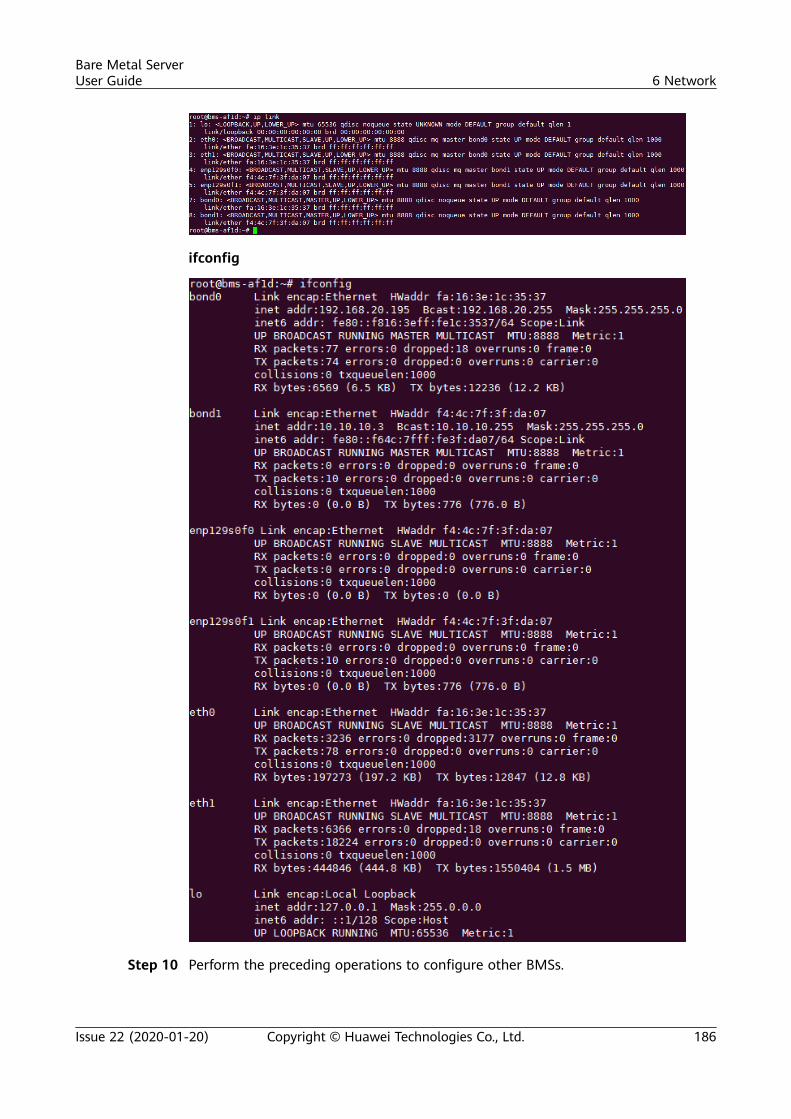
ifconfig
Step 10 Perform the preceding operations to configure other BMSs.
Bare Metal ServerUser Guide 6 Network
Issue 22 (2020-01-20) Copyright © Huawei Technologies Co., Ltd. 186
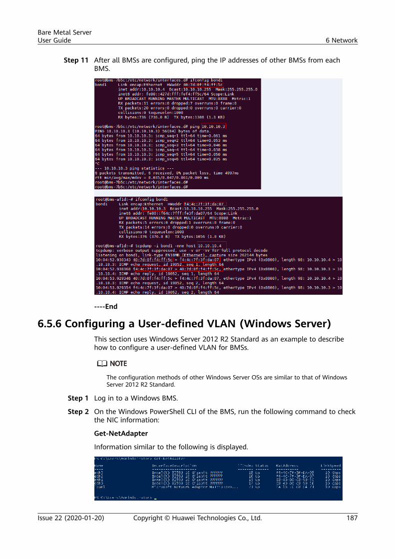
Step 11 After all BMSs are configured, ping the IP addresses of other BMSs from eachBMS.
----End
6.5.6 Configuring a User-defined VLAN (Windows Server)This section uses Windows Server 2012 R2 Standard as an example to describehow to configure a user-defined VLAN for BMSs.
The configuration methods of other Windows Server OSs are similar to that of WindowsServer 2012 R2 Standard.
Step 1 Log in to a Windows BMS.
Step 2 On the Windows PowerShell CLI of the BMS, run the following command to checkthe NIC information:
Get-NetAdapter
Information similar to the following is displayed.
Bare Metal ServerUser Guide 6 Network
Issue 22 (2020-01-20) Copyright © Huawei Technologies Co., Ltd. 187
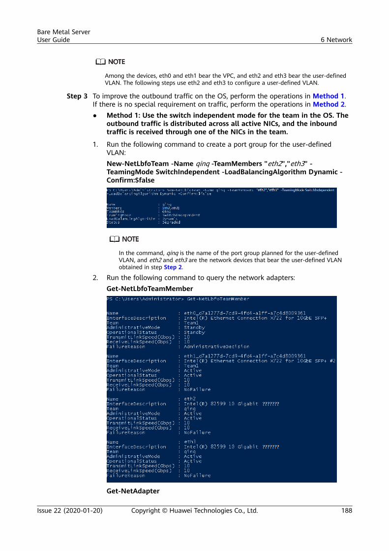
Among the devices, eth0 and eth1 bear the VPC, and eth2 and eth3 bear the user-definedVLAN. The following steps use eth2 and eth3 to configure a user-defined VLAN.
Step 3 To improve the outbound traffic on the OS, perform the operations in Method 1.If there is no special requirement on traffic, perform the operations in Method 2.● Method 1: Use the switch independent mode for the team in the OS. The
outbound traffic is distributed across all active NICs, and the inboundtraffic is received through one of the NICs in the team.
1. Run the following command to create a port group for the user-definedVLAN:New-NetLbfoTeam -Name qinq -TeamMembers "eth2","eth3" -TeamingMode SwitchIndependent -LoadBalancingAlgorithm Dynamic -Confirm:$false
In the command, qinq is the name of the port group planned for the user-definedVLAN, and eth2 and eth3 are the network devices that bear the user-defined VLANobtained in step Step 2.
2. Run the following command to query the network adapters:Get-NetLbfoTeamMember
Get-NetAdapter
Bare Metal ServerUser Guide 6 Network
Issue 22 (2020-01-20) Copyright © Huawei Technologies Co., Ltd. 188
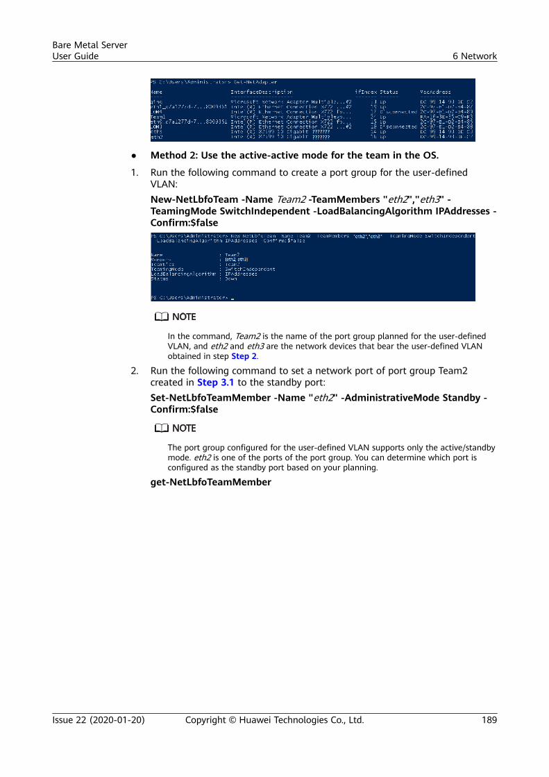
● Method 2: Use the active-active mode for the team in the OS.
1. Run the following command to create a port group for the user-definedVLAN:New-NetLbfoTeam -Name Team2 -TeamMembers "eth2","eth3" -TeamingMode SwitchIndependent -LoadBalancingAlgorithm IPAddresses -Confirm:$false
In the command, Team2 is the name of the port group planned for the user-definedVLAN, and eth2 and eth3 are the network devices that bear the user-defined VLANobtained in step Step 2.
2. Run the following command to set a network port of port group Team2created in Step 3.1 to the standby port:Set-NetLbfoTeamMember -Name "eth2" -AdministrativeMode Standby -Confirm:$false
The port group configured for the user-defined VLAN supports only the active/standbymode. eth2 is one of the ports of the port group. You can determine which port isconfigured as the standby port based on your planning.
get-NetLbfoTeamMember
Bare Metal ServerUser Guide 6 Network
Issue 22 (2020-01-20) Copyright © Huawei Technologies Co., Ltd. 189
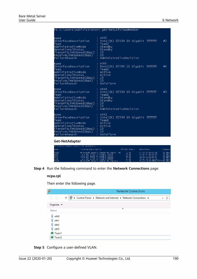
Get-NetAdapter
Step 4 Run the following command to enter the Network Connections page:
ncpa.cpl
Then enter the following page.
Step 5 Configure a user-defined VLAN.
Bare Metal ServerUser Guide 6 Network
Issue 22 (2020-01-20) Copyright © Huawei Technologies Co., Ltd. 190
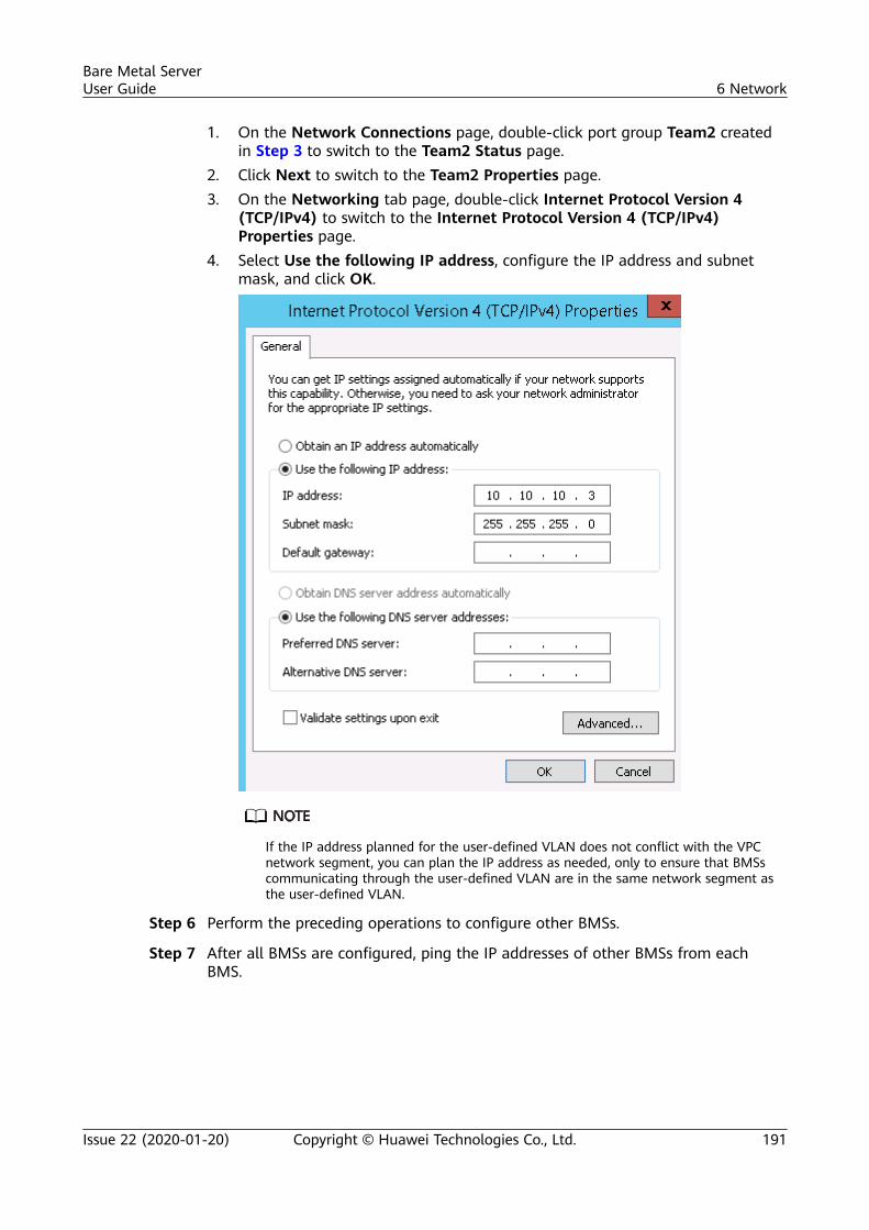
1. On the Network Connections page, double-click port group Team2 createdin Step 3 to switch to the Team2 Status page.
2. Click Next to switch to the Team2 Properties page.3. On the Networking tab page, double-click Internet Protocol Version 4
(TCP/IPv4) to switch to the Internet Protocol Version 4 (TCP/IPv4)Properties page.
4. Select Use the following IP address, configure the IP address and subnetmask, and click OK.
If the IP address planned for the user-defined VLAN does not conflict with the VPCnetwork segment, you can plan the IP address as needed, only to ensure that BMSscommunicating through the user-defined VLAN are in the same network segment asthe user-defined VLAN.
Step 6 Perform the preceding operations to configure other BMSs.
Step 7 After all BMSs are configured, ping the IP addresses of other BMSs from eachBMS.
Bare Metal ServerUser Guide 6 Network
Issue 22 (2020-01-20) Copyright © Huawei Technologies Co., Ltd. 191
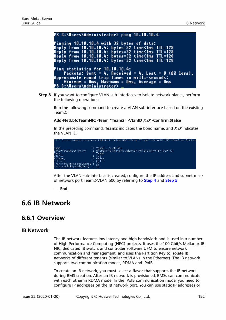
Step 8 If you want to configure VLAN sub-interfaces to isolate network planes, performthe following operations:
Run the following command to create a VLAN sub-interface based on the existingTeam2:
Add-NetLbfoTeamNIC -Team "Team2" -VlanID XXX -Confirm:$false
In the preceding command, Team2 indicates the bond name, and XXX indicatesthe VLAN ID.
After the VLAN sub-interface is created, configure the IP address and subnet maskof network port Team2-VLAN 500 by referring to Step 4 and Step 5.
----End
6.6 IB Network
6.6.1 Overview
IB NetworkThe IB network features low latency and high bandwidth and is used in a numberof High Performance Computing (HPC) projects. It uses the 100 Gbit/s Mellanox IBNIC, dedicated IB switch, and controller software UFM to ensure networkcommunication and management, and uses the Partition Key to isolate IBnetworks of different tenants (similar to VLANs in the Ethernet). The IB networksupports two communication modes, RDMA and IPoIB.
To create an IB network, you must select a flavor that supports the IB networkduring BMS creation. After an IB network is provisioned, BMSs can communicatewith each other in RDMA mode. In the IPoIB communication mode, you need toconfigure IP addresses on the IB network port. You can use static IP addresses or
Bare Metal ServerUser Guide 6 Network
Issue 22 (2020-01-20) Copyright © Huawei Technologies Co., Ltd. 192
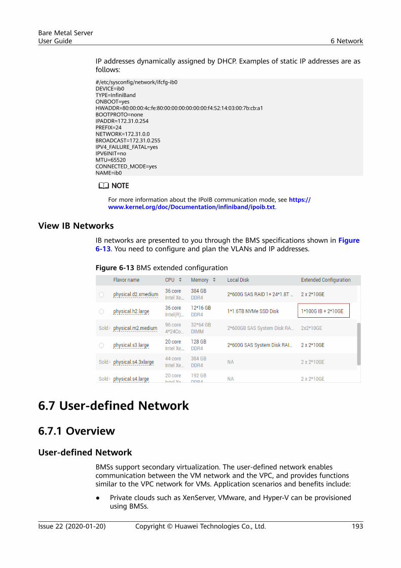
IP addresses dynamically assigned by DHCP. Examples of static IP addresses are asfollows:
#/etc/sysconfig/network/ifcfg-ib0DEVICE=ib0TYPE=InfiniBandONBOOT=yesHWADDR=80:00:00:4c:fe:80:00:00:00:00:00:00:f4:52:14:03:00:7b:cb:a1BOOTPROTO=noneIPADDR=172.31.0.254PREFIX=24NETWORK=172.31.0.0BROADCAST=172.31.0.255IPV4_FAILURE_FATAL=yesIPV6INIT=noMTU=65520CONNECTED_MODE=yesNAME=ib0
For more information about the IPoIB communication mode, see https://www.kernel.org/doc/Documentation/infiniband/ipoib.txt.
View IB NetworksIB networks are presented to you through the BMS specifications shown in Figure6-13. You need to configure and plan the VLANs and IP addresses.
Figure 6-13 BMS extended configuration
6.7 User-defined Network
6.7.1 Overview
User-defined NetworkBMSs support secondary virtualization. The user-defined network enablescommunication between the VM network and the VPC, and provides functionssimilar to the VPC network for VMs. Application scenarios and benefits include:
● Private clouds such as XenServer, VMware, and Hyper-V can be provisionedusing BMSs.
Bare Metal ServerUser Guide 6 Network
Issue 22 (2020-01-20) Copyright © Huawei Technologies Co., Ltd. 193
● VMs or containers provisioned in the private cloud on BMSs can communicatewith the Internet.
● VMs or containers provisioned in the private cloud on BMSs can communicatewith each other.
● Network ACLs can be configured for the subnets of the VMs or containersprovisioned in the private cloud on BMSs.
● VMs or containers provisioned in the private cloud on BMSs can communicatewith ECSs in VPCs.
● The private cloud system based on BMSs and Direct Connect cancommunicate with the private cloud in the on-premise data center.
The best practice Virtualization on BMS is provided for you to use user-definednetworks. For details, see Virtualization on BMS.
Notes● Currently, user-defined networks are only available in the CN North-Beijing1,
AP-Bangkok, and CN South-Guangzhou regions.User-defined networks in CN North-Beijing1 and AP-Bangkok are phase 1,and those in CN South-Guangzhou are phase 2, which provide the followingadditional functions:– A user-defined network can have a maximum of 200 user-defined
subnets.– VLANs can be configured for user-defined subnets.– User-defined network ACLs are available, which control incoming and
outgoing traffic of user-defined subnets.● If you have multiple VPCs, you can only create user-defined networks in one
VPC.● If each of your BMSs has only one NIC, you cannot create user-defined
networks.● You must create a BMS with a user-defined VLAN before creating a user-
defined network.● Security groups cannot be configured for user-defined subnets.
6.7.2 Creating and Managing a User-defined Network
Create a User-defined Network
This section describes how to create a user-defined network in the CN South-Guangzhouregion. For details about user-defined networks in CN North-Beijing1 and AP-Bangkok, seeNotes.
1. Log in to the management console.2. Under Computing, click Bare Metal Server.
The BMS console is displayed.3. Click the User-defined Networks tab and click Create User-defined
Network.
Bare Metal ServerUser Guide 6 Network
Issue 22 (2020-01-20) Copyright © Huawei Technologies Co., Ltd. 194
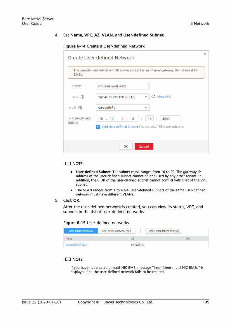
4. Set Name, VPC, AZ, VLAN, and User-defined Subnet.
Figure 6-14 Create a User-defined Network
● User-defined Subnet: The subnet mask ranges from 16 to 29. The gateway IPaddress of the user-defined subnet cannot be one used by any other tenant. Inaddition, the CIDR of the user-defined subnet cannot conflict with that of the VPCsubnet.
● The VLAN ranges from 1 to 4094. User-defined subnets of the same user-definednetwork must have different VLANs.
5. Click OK.After the user-defined network is created, you can view its status, VPC, andsubnets in the list of user-defined networks.
Figure 6-15 User-defined networks
If you have not created a multi-NIC BMS, message "Insufficient multi-NIC BMSs." isdisplayed and the user-defined network fails to be created.
Bare Metal ServerUser Guide 6 Network
Issue 22 (2020-01-20) Copyright © Huawei Technologies Co., Ltd. 195
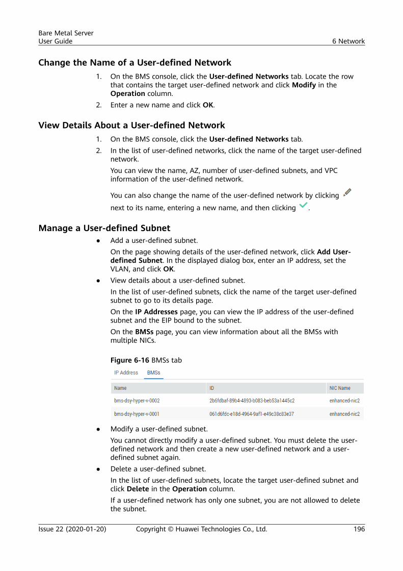
Change the Name of a User-defined Network1. On the BMS console, click the User-defined Networks tab. Locate the row
that contains the target user-defined network and click Modify in theOperation column.
2. Enter a new name and click OK.
View Details About a User-defined Network1. On the BMS console, click the User-defined Networks tab.2. In the list of user-defined networks, click the name of the target user-defined
network.You can view the name, AZ, number of user-defined subnets, and VPCinformation of the user-defined network.
You can also change the name of the user-defined network by clicking
next to its name, entering a new name, and then clicking .
Manage a User-defined Subnet● Add a user-defined subnet.
On the page showing details of the user-defined network, click Add User-defined Subnet. In the displayed dialog box, enter an IP address, set theVLAN, and click OK.
● View details about a user-defined subnet.In the list of user-defined subnets, click the name of the target user-definedsubnet to go to its details page.On the IP Addresses page, you can view the IP address of the user-definedsubnet and the EIP bound to the subnet.On the BMSs page, you can view information about all the BMSs withmultiple NICs.
Figure 6-16 BMSs tab
● Modify a user-defined subnet.You cannot directly modify a user-defined subnet. You must delete the user-defined network and then create a new user-defined network and a user-defined subnet again.
● Delete a user-defined subnet.In the list of user-defined subnets, locate the target user-defined subnet andclick Delete in the Operation column.If a user-defined network has only one subnet, you are not allowed to deletethe subnet.
Bare Metal ServerUser Guide 6 Network
Issue 22 (2020-01-20) Copyright © Huawei Technologies Co., Ltd. 196
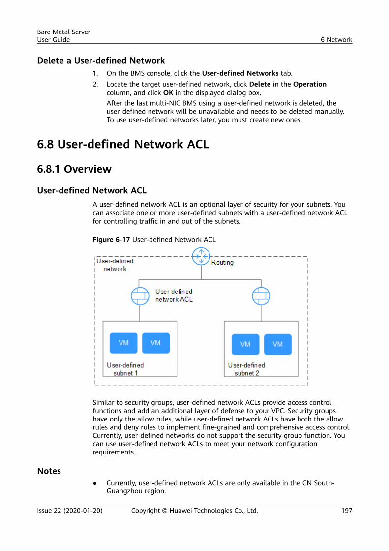
Delete a User-defined Network1. On the BMS console, click the User-defined Networks tab.2. Locate the target user-defined network, click Delete in the Operation
column, and click OK in the displayed dialog box.After the last multi-NIC BMS using a user-defined network is deleted, theuser-defined network will be unavailable and needs to be deleted manually.To use user-defined networks later, you must create new ones.
6.8 User-defined Network ACL
6.8.1 Overview
User-defined Network ACLA user-defined network ACL is an optional layer of security for your subnets. Youcan associate one or more user-defined subnets with a user-defined network ACLfor controlling traffic in and out of the subnets.
Figure 6-17 User-defined Network ACL
Similar to security groups, user-defined network ACLs provide access controlfunctions and add an additional layer of defense to your VPC. Security groupshave only the allow rules, while user-defined network ACLs have both the allowrules and deny rules to implement fine-grained and comprehensive access control.Currently, user-defined networks do not support the security group function. Youcan use user-defined network ACLs to meet your network configurationrequirements.
Notes● Currently, user-defined network ACLs are only available in the CN South-
Guangzhou region.
Bare Metal ServerUser Guide 6 Network
Issue 22 (2020-01-20) Copyright © Huawei Technologies Co., Ltd. 197
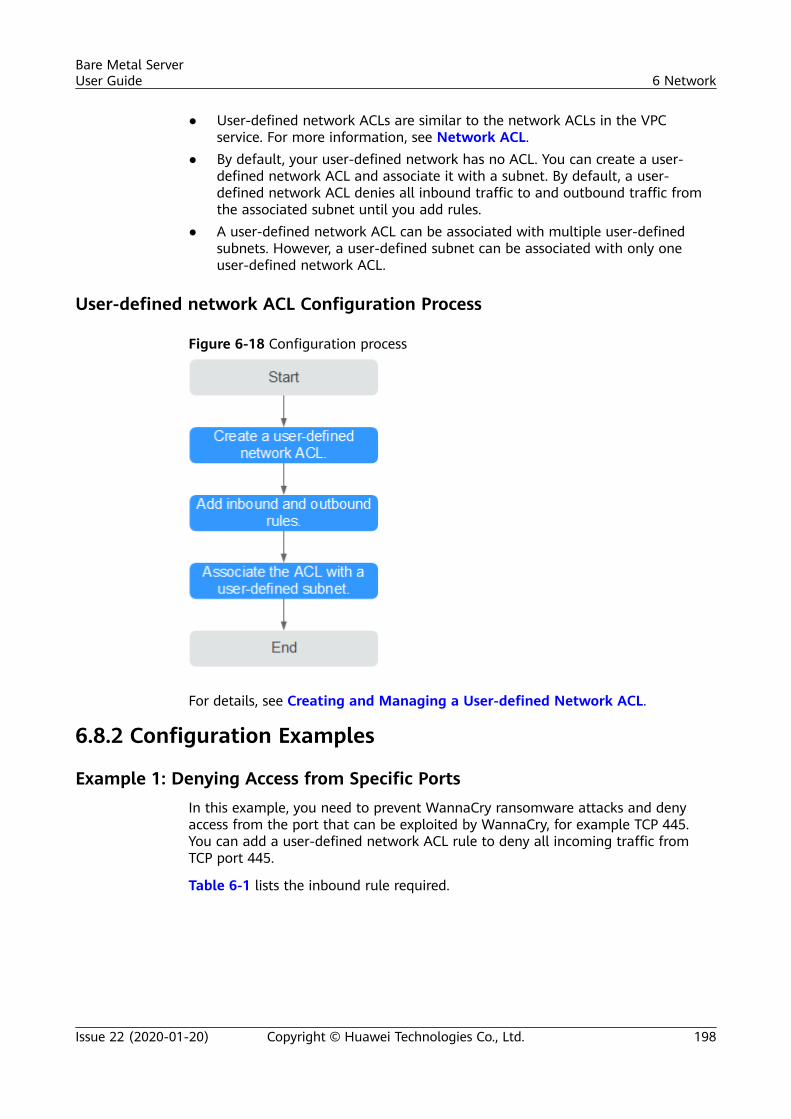
● User-defined network ACLs are similar to the network ACLs in the VPCservice. For more information, see Network ACL.
● By default, your user-defined network has no ACL. You can create a user-defined network ACL and associate it with a subnet. By default, a user-defined network ACL denies all inbound traffic to and outbound traffic fromthe associated subnet until you add rules.
● A user-defined network ACL can be associated with multiple user-definedsubnets. However, a user-defined subnet can be associated with only oneuser-defined network ACL.
User-defined network ACL Configuration Process
Figure 6-18 Configuration process
For details, see Creating and Managing a User-defined Network ACL.
6.8.2 Configuration Examples
Example 1: Denying Access from Specific PortsIn this example, you need to prevent WannaCry ransomware attacks and denyaccess from the port that can be exploited by WannaCry, for example TCP 445.You can add a user-defined network ACL rule to deny all incoming traffic fromTCP port 445.
Table 6-1 lists the inbound rule required.
Bare Metal ServerUser Guide 6 Network
Issue 22 (2020-01-20) Copyright © Huawei Technologies Co., Ltd. 198
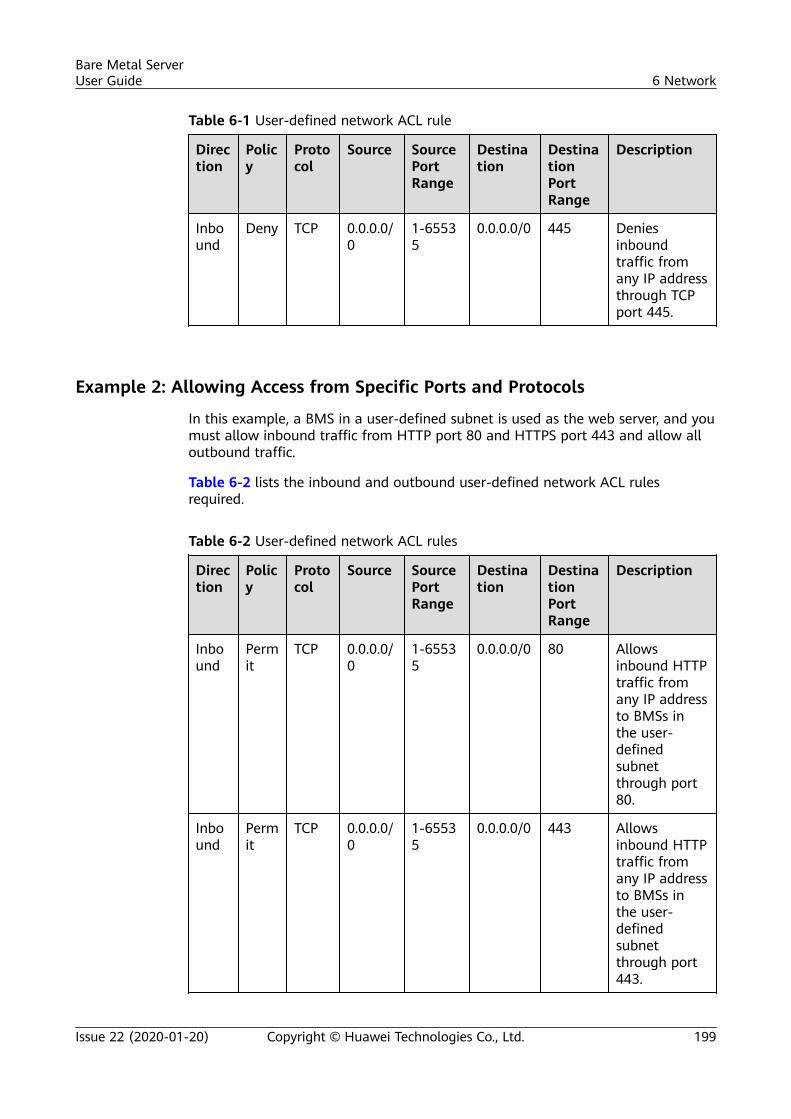
Table 6-1 User-defined network ACL rule
Direction
Policy
Protocol
Source SourcePortRange
Destination
DestinationPortRange
Description
Inbound
Deny TCP 0.0.0.0/0
1-65535
0.0.0.0/0 445 Deniesinboundtraffic fromany IP addressthrough TCPport 445.
Example 2: Allowing Access from Specific Ports and Protocols
In this example, a BMS in a user-defined subnet is used as the web server, and youmust allow inbound traffic from HTTP port 80 and HTTPS port 443 and allow alloutbound traffic.
Table 6-2 lists the inbound and outbound user-defined network ACL rulesrequired.
Table 6-2 User-defined network ACL rules
Direction
Policy
Protocol
Source SourcePortRange
Destination
DestinationPortRange
Description
Inbound
Permit
TCP 0.0.0.0/0
1-65535
0.0.0.0/0 80 Allowsinbound HTTPtraffic fromany IP addressto BMSs inthe user-definedsubnetthrough port80.
Inbound
Permit
TCP 0.0.0.0/0
1-65535
0.0.0.0/0 443 Allowsinbound HTTPtraffic fromany IP addressto BMSs inthe user-definedsubnetthrough port443.
Bare Metal ServerUser Guide 6 Network
Issue 22 (2020-01-20) Copyright © Huawei Technologies Co., Ltd. 199
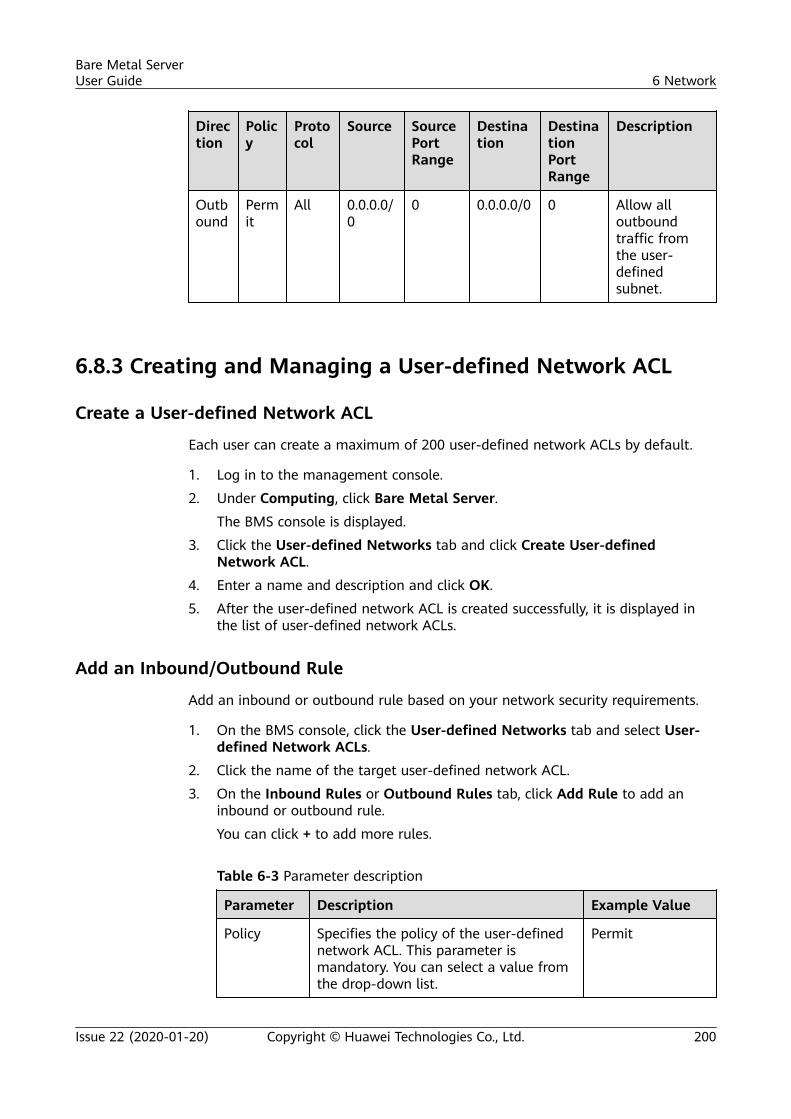
Direction
Policy
Protocol
Source SourcePortRange
Destination
DestinationPortRange
Description
Outbound
Permit
All 0.0.0.0/0
0 0.0.0.0/0 0 Allow alloutboundtraffic fromthe user-definedsubnet.
6.8.3 Creating and Managing a User-defined Network ACL
Create a User-defined Network ACL
Each user can create a maximum of 200 user-defined network ACLs by default.
1. Log in to the management console.
2. Under Computing, click Bare Metal Server.
The BMS console is displayed.
3. Click the User-defined Networks tab and click Create User-definedNetwork ACL.
4. Enter a name and description and click OK.
5. After the user-defined network ACL is created successfully, it is displayed inthe list of user-defined network ACLs.
Add an Inbound/Outbound Rule
Add an inbound or outbound rule based on your network security requirements.
1. On the BMS console, click the User-defined Networks tab and select User-defined Network ACLs.
2. Click the name of the target user-defined network ACL.
3. On the Inbound Rules or Outbound Rules tab, click Add Rule to add aninbound or outbound rule.
You can click + to add more rules.
Table 6-3 Parameter description
Parameter Description Example Value
Policy Specifies the policy of the user-definednetwork ACL. This parameter ismandatory. You can select a value fromthe drop-down list.
Permit
Bare Metal ServerUser Guide 6 Network
Issue 22 (2020-01-20) Copyright © Huawei Technologies Co., Ltd. 200
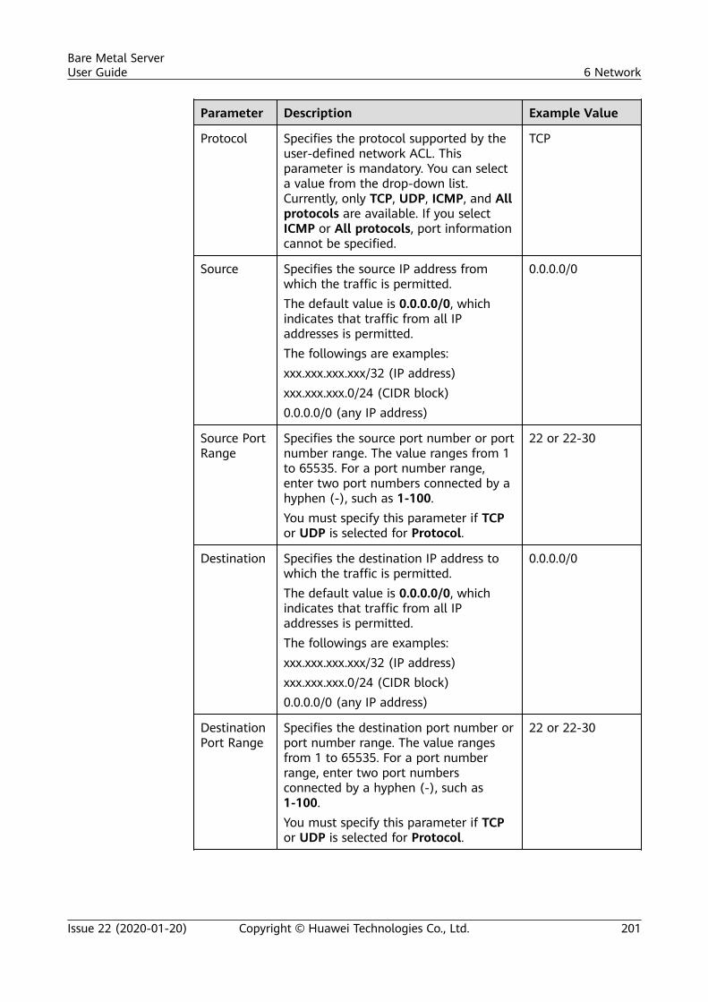
Parameter Description Example Value
Protocol Specifies the protocol supported by theuser-defined network ACL. Thisparameter is mandatory. You can selecta value from the drop-down list.Currently, only TCP, UDP, ICMP, and Allprotocols are available. If you selectICMP or All protocols, port informationcannot be specified.
TCP
Source Specifies the source IP address fromwhich the traffic is permitted.The default value is 0.0.0.0/0, whichindicates that traffic from all IPaddresses is permitted.The followings are examples:xxx.xxx.xxx.xxx/32 (IP address)xxx.xxx.xxx.0/24 (CIDR block)0.0.0.0/0 (any IP address)
0.0.0.0/0
Source PortRange
Specifies the source port number or portnumber range. The value ranges from 1to 65535. For a port number range,enter two port numbers connected by ahyphen (-), such as 1-100.You must specify this parameter if TCPor UDP is selected for Protocol.
22 or 22-30
Destination Specifies the destination IP address towhich the traffic is permitted.The default value is 0.0.0.0/0, whichindicates that traffic from all IPaddresses is permitted.The followings are examples:xxx.xxx.xxx.xxx/32 (IP address)xxx.xxx.xxx.0/24 (CIDR block)0.0.0.0/0 (any IP address)
0.0.0.0/0
DestinationPort Range
Specifies the destination port number orport number range. The value rangesfrom 1 to 65535. For a port numberrange, enter two port numbersconnected by a hyphen (-), such as1-100.You must specify this parameter if TCPor UDP is selected for Protocol.
22 or 22-30
Bare Metal ServerUser Guide 6 Network
Issue 22 (2020-01-20) Copyright © Huawei Technologies Co., Ltd. 201
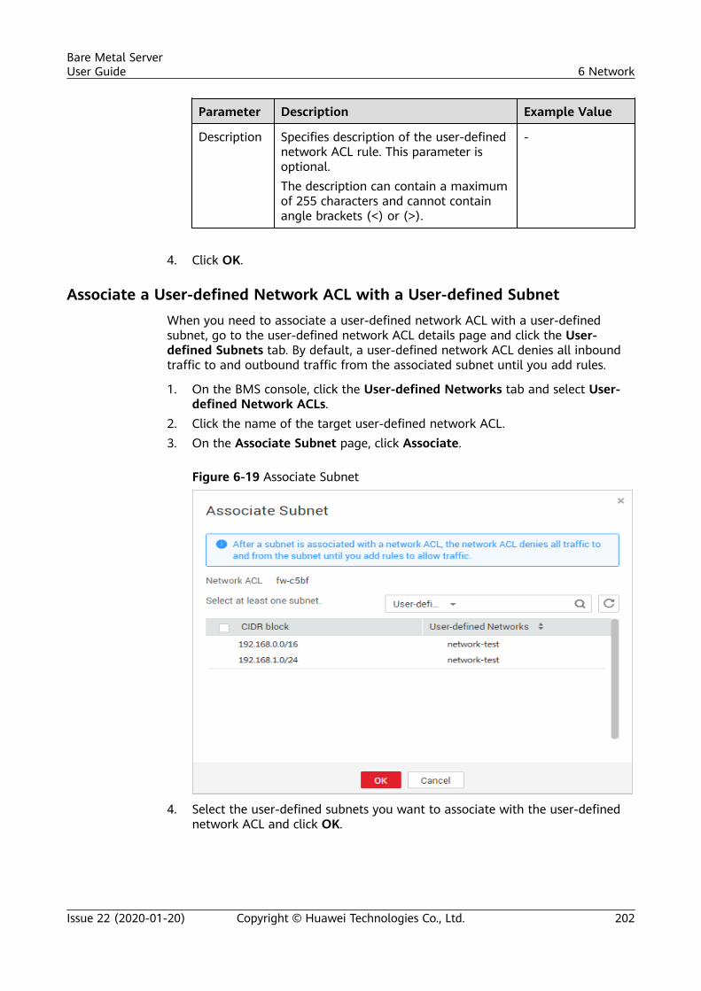
Parameter Description Example Value
Description Specifies description of the user-definednetwork ACL rule. This parameter isoptional.The description can contain a maximumof 255 characters and cannot containangle brackets (<) or (>).
-
4. Click OK.
Associate a User-defined Network ACL with a User-defined SubnetWhen you need to associate a user-defined network ACL with a user-definedsubnet, go to the user-defined network ACL details page and click the User-defined Subnets tab. By default, a user-defined network ACL denies all inboundtraffic to and outbound traffic from the associated subnet until you add rules.
1. On the BMS console, click the User-defined Networks tab and select User-defined Network ACLs.
2. Click the name of the target user-defined network ACL.3. On the Associate Subnet page, click Associate.
Figure 6-19 Associate Subnet
4. Select the user-defined subnets you want to associate with the user-definednetwork ACL and click OK.
Bare Metal ServerUser Guide 6 Network
Issue 22 (2020-01-20) Copyright © Huawei Technologies Co., Ltd. 202

User-defined subnets that have already been associated with user-defined networkACLs will not be displayed on the page for you to select. One-click user-defined subnetassociation and disassociation are not supported. If you want to associate a user-defined subnet that has already been associated with another user-defined networkACL, you must first disassociate the subnet from the original network ACL.
Bare Metal ServerUser Guide 6 Network
Issue 22 (2020-01-20) Copyright © Huawei Technologies Co., Ltd. 203
7 Security
7.1 Security Group
7.1.1 Adding Security Group Rules
Scenarios
The default security group rule allows all outgoing data packets. BMSs in asecurity group can access each other without the need to add access rules. After asecurity group is created, you can create different access rules for the securitygroup to protect the BMSs that are added to this security group.
You can add only one security group when creating a BMS. After the BMS is created, youcan modify the security group of each NIC on the BMS details page.
Suggestions● When adding a security group rule for a BMS, grant the minimum permissions
possible:
– Enable specific ports rather than a port range, for example, port 80.
– Be cautious to authorize source address 0.0.0.0/0 (entire networksegment).
● You are not advised to use one security group to manage all applicationsbecause isolation requirements for different layers vary.
● Configuring a security group for each BMS is unnecessary. Instead, you canadd BMSs with the same security protection requirements to the samesecurity group.
● Simple security group rules are recommended. For example, if you add a BMSto multiple security groups, the BMS may comply with hundreds of securitygroup rules, and a change to any rule may cause network disconnection forthe BMS.
Bare Metal ServerUser Guide 7 Security
Issue 22 (2020-01-20) Copyright © Huawei Technologies Co., Ltd. 204
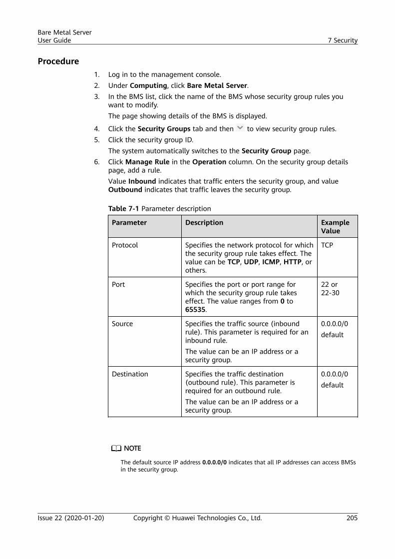
Procedure1. Log in to the management console.2. Under Computing, click Bare Metal Server.3. In the BMS list, click the name of the BMS whose security group rules you
want to modify.The page showing details of the BMS is displayed.
4. Click the Security Groups tab and then to view security group rules.5. Click the security group ID.
The system automatically switches to the Security Group page.6. Click Manage Rule in the Operation column. On the security group details
page, add a rule.Value Inbound indicates that traffic enters the security group, and valueOutbound indicates that traffic leaves the security group.
Table 7-1 Parameter description
Parameter Description ExampleValue
Protocol Specifies the network protocol for whichthe security group rule takes effect. Thevalue can be TCP, UDP, ICMP, HTTP, orothers.
TCP
Port Specifies the port or port range forwhich the security group rule takeseffect. The value ranges from 0 to65535.
22 or22-30
Source Specifies the traffic source (inboundrule). This parameter is required for aninbound rule.The value can be an IP address or asecurity group.
0.0.0.0/0default
Destination Specifies the traffic destination(outbound rule). This parameter isrequired for an outbound rule.The value can be an IP address or asecurity group.
0.0.0.0/0default
The default source IP address 0.0.0.0/0 indicates that all IP addresses can access BMSsin the security group.
Bare Metal ServerUser Guide 7 Security
Issue 22 (2020-01-20) Copyright © Huawei Technologies Co., Ltd. 205
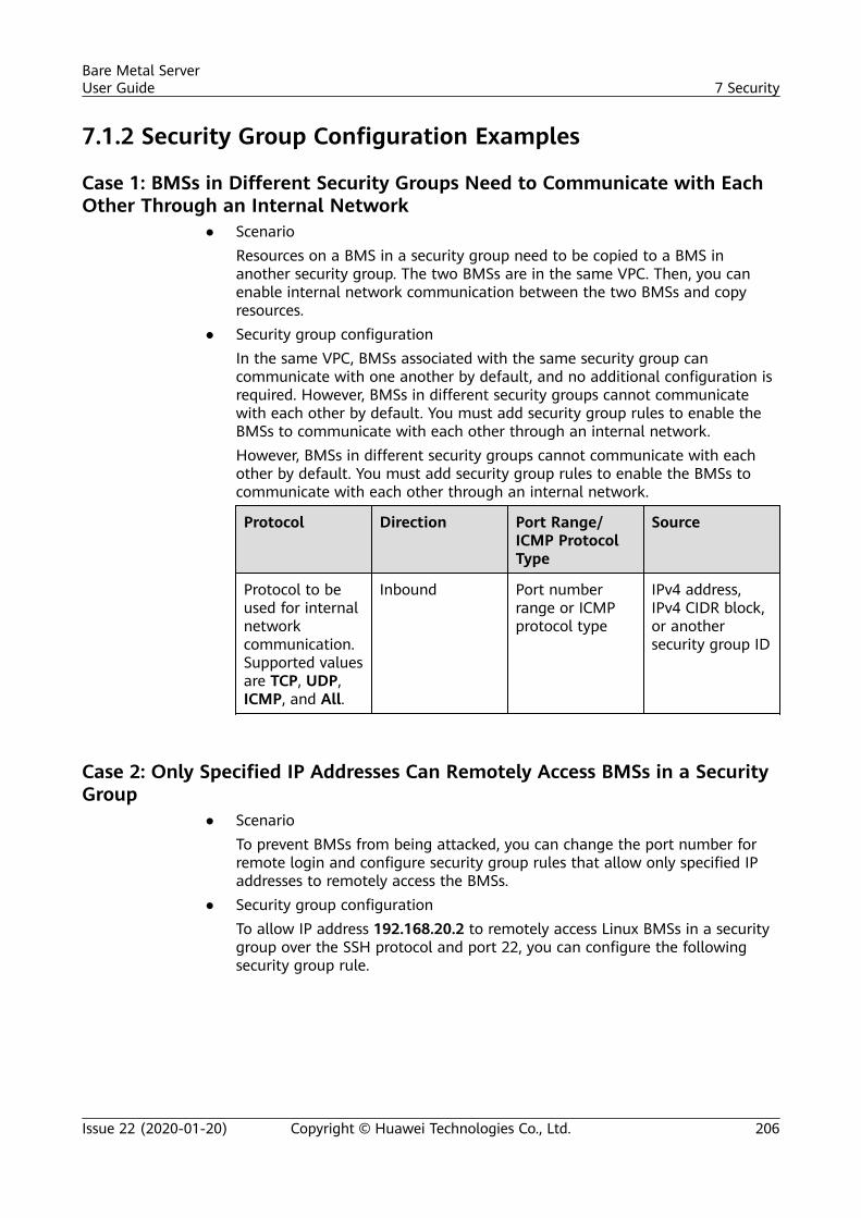
7.1.2 Security Group Configuration Examples
Case 1: BMSs in Different Security Groups Need to Communicate with EachOther Through an Internal Network
● ScenarioResources on a BMS in a security group need to be copied to a BMS inanother security group. The two BMSs are in the same VPC. Then, you canenable internal network communication between the two BMSs and copyresources.
● Security group configurationIn the same VPC, BMSs associated with the same security group cancommunicate with one another by default, and no additional configuration isrequired. However, BMSs in different security groups cannot communicatewith each other by default. You must add security group rules to enable theBMSs to communicate with each other through an internal network.However, BMSs in different security groups cannot communicate with eachother by default. You must add security group rules to enable the BMSs tocommunicate with each other through an internal network.
Protocol Direction Port Range/ICMP ProtocolType
Source
Protocol to beused for internalnetworkcommunication.Supported valuesare TCP, UDP,ICMP, and All.
Inbound Port numberrange or ICMPprotocol type
IPv4 address,IPv4 CIDR block,or anothersecurity group ID
Case 2: Only Specified IP Addresses Can Remotely Access BMSs in a SecurityGroup
● ScenarioTo prevent BMSs from being attacked, you can change the port number forremote login and configure security group rules that allow only specified IPaddresses to remotely access the BMSs.
● Security group configurationTo allow IP address 192.168.20.2 to remotely access Linux BMSs in a securitygroup over the SSH protocol and port 22, you can configure the followingsecurity group rule.
Bare Metal ServerUser Guide 7 Security
Issue 22 (2020-01-20) Copyright © Huawei Technologies Co., Ltd. 206
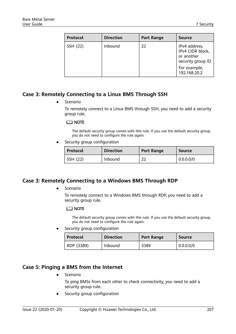
Protocol Direction Port Range Source
SSH (22) Inbound 22 IPv4 address,IPv4 CIDR block,or anothersecurity group IDFor example,192.168.20.2
Case 3: Remotely Connecting to a Linux BMS Through SSH● Scenario
To remotely connect to a Linux BMS through SSH, you need to add a securitygroup rule.
The default security group comes with this rule. If you use the default security group,you do not need to configure the rule again.
● Security group configuration
Protocol Direction Port Range Source
SSH (22) Inbound 22 0.0.0.0/0
Case 3: Remotely Connecting to a Windows BMS Through RDP● Scenario
To remotely connect to a Windows BMS through RDP, you need to add asecurity group rule.
The default security group comes with this rule. If you use the default security group,you do not need to configure the rule again.
● Security group configuration
Protocol Direction Port Range Source
RDP (3389) Inbound 3389 0.0.0.0/0
Case 5: Pinging a BMS from the Internet● Scenario
To ping BMSs from each other to check connectivity, you need to add asecurity group rule.
● Security group configuration
Bare Metal ServerUser Guide 7 Security
Issue 22 (2020-01-20) Copyright © Huawei Technologies Co., Ltd. 207
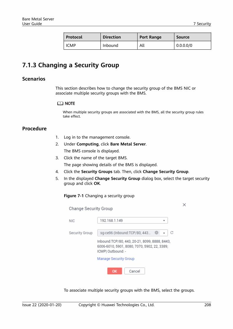
Protocol Direction Port Range Source
ICMP Inbound All 0.0.0.0/0
7.1.3 Changing a Security Group
Scenarios
This section describes how to change the security group of the BMS NIC orassociate multiple security groups with the BMS.
When multiple security groups are associated with the BMS, all the security group rulestake effect.
Procedure1. Log in to the management console.
2. Under Computing, click Bare Metal Server.
The BMS console is displayed.
3. Click the name of the target BMS.
The page showing details of the BMS is displayed.
4. Click the Security Groups tab. Then, click Change Security Group.
5. In the displayed Change Security Group dialog box, select the target securitygroup and click OK.
Figure 7-1 Changing a security group
To associate multiple security groups with the BMS, select the groups.
Bare Metal ServerUser Guide 7 Security
Issue 22 (2020-01-20) Copyright © Huawei Technologies Co., Ltd. 208
Result
On the BMS details page, click the Security Groups tab. The security group hasbeen changed, or new security groups are contained in the list.
7.2 Project and Enterprise Project
Create a Project and Assign Permissions● Creating a project
Log in to the management console, click the username in the upper rightcorner, and select Identity and Access Management from the drop-down listbox. In the navigation pane on the left, choose Projects. In the right pane,click Create Project. On the displayed Create Project page, select a regionand enter a project name.
● Assigning permissionsYou can assign permissions (of resources and operations) to user groups toassociate projects with user groups. You can add users to a user group tocontrol projects users can access and the resources on which users canperform operations. The procedure is as follows:
a. On the User Groups page, locate the target user group and clickConfigure Permission in the Operation column. The User GroupPermissions page is displayed. Locate the row that contains the targetproject, click Configure Policy, and select the required policies for theproject.
b. On the Users page, locate the target user and click Modify in theOperation column. In the User Groups area, add a user group for theuser.
Create an Enterprise Project and Assign Permissions● Creating an enterprise project
On the management console, click Enterprise in the upper right corner. TheEnterprise Management page is displayed. In the navigation pane on theleft, choose Enterprise Project Management. In the right pane, click CreateEnterprise Project and enter a name.
Enterprise is available on the management console only if you have enabled theenterprise project, or your account is the primary account. To enable this function,contact your customer manager.
● Assigning permissionsYou can add a user group to an enterprise project and configure a policy toassociate the enterprise project with the user group. You can add users to auser group to control projects users can access and the resources on whichusers can perform operations. The procedure is as follows:
a. Locate the row that contains the target enterprise project, click More inthe Operation column, and select View User Group. On the displayedUser Groups page, click Add User Group. In the displayed Add User
Bare Metal ServerUser Guide 7 Security
Issue 22 (2020-01-20) Copyright © Huawei Technologies Co., Ltd. 209
Group dialog box, select the user groups you want to add and movethem to the right pane. Click Next and select the policies.
b. In the navigation pane on the left, choose Personnel Management >User Management. Locate the row that contains the target user, clickMore in the Operation column, and select Add to User Group. In thedisplayed Add to User Group dialog box, select the user groups for whichpolicies have been configured and click OK.
● Associating BMSs with enterprise projectsYou can manage BMSs by enterprise project. To associate BMSs withenterprise projects, perform the following operations:– Select an enterprise project when buying a BMS.
On the page for buying a BMS, select an enterprise project from theEnterprise Project drop-down list.
– Add BMSs to an enterprise project.On the Enterprise Project Management page, you can add existingBMSs to an enterprise project.Value default indicates the default enterprise project. Resources that arenot allocated to any enterprise projects under your account are displayedin the default enterprise project.
For more information, see Enterprise Management User Guide.
Bare Metal ServerUser Guide 7 Security
Issue 22 (2020-01-20) Copyright © Huawei Technologies Co., Ltd. 210
8 Permissions Management
8.1 Creating a User and Granting PermissionsThis section describes how to use IAM to implement fine-grained permissionscontrol for your BMS resources. With IAM, you can:
● Create IAM users for employees based on the organizational structure of yourenterprise. Each IAM user has their own security credentials, providing accessto BMS resources.
● Grant only the permissions required for users to perform a task.● Entrust a HUAWEI CLOUD account or cloud service to perform professional
and efficient O&M on your BMS resources.
If your HUAWEI CLOUD account does not need individual IAM users, you can skipover this section.
This section uses the BMS ReadOnlyAccess policy as an example to describe howto grant permissions to a user. Figure 8-1 shows the process.
PrerequisitesLearn about the system permissions (see Permissions Management) supportedby BMS and choose permissions based on your requirements. For the permissionsof other services, see Permissions Policies.
Bare Metal ServerUser Guide 8 Permissions Management
Issue 22 (2020-01-20) Copyright © Huawei Technologies Co., Ltd. 211
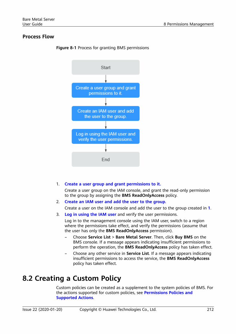
Process Flow
Figure 8-1 Process for granting BMS permissions
1. Create a user group and grant permissions to it.Create a user group on the IAM console, and grant the read-only permissionto the group by assigning the BMS ReadOnlyAccess policy.
2. Create an IAM user and add the user to the group.Create a user on the IAM console and add the user to the group created in 1.
3. Log in using the IAM user and verify the user permissions.Log in to the management console using the IAM user, switch to a regionwhere the permissions take effect, and verify the permissions (assume thatthe user has only the BMS ReadOnlyAccess permission).– Choose Service List > Bare Metal Server. Then, click Buy BMS on the
BMS console. If a message appears indicating insufficient permissions toperform the operation, the BMS ReadOnlyAccess policy has taken effect.
– Choose any other service in Service List. If a message appears indicatinginsufficient permissions to access the service, the BMS ReadOnlyAccesspolicy has taken effect.
8.2 Creating a Custom PolicyCustom policies can be created as a supplement to the system policies of BMS. Forthe actions supported for custom policies, see Permissions Policies andSupported Actions.
Bare Metal ServerUser Guide 8 Permissions Management
Issue 22 (2020-01-20) Copyright © Huawei Technologies Co., Ltd. 212
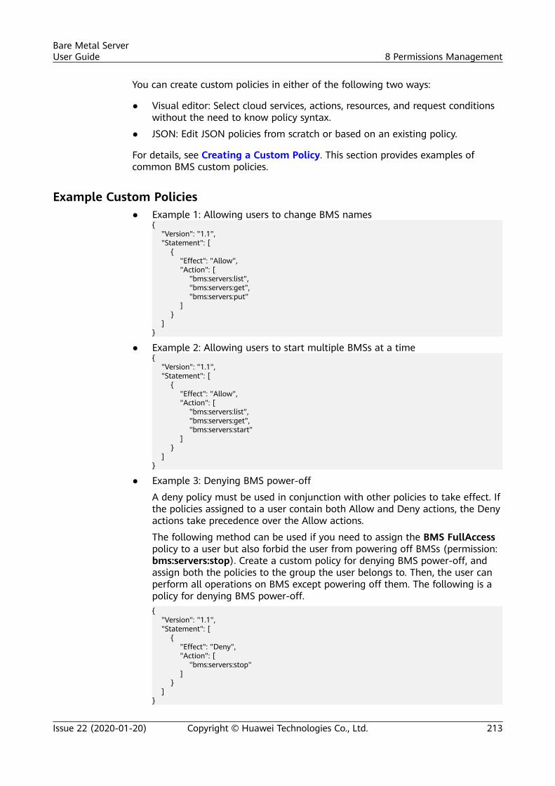
You can create custom policies in either of the following two ways:
● Visual editor: Select cloud services, actions, resources, and request conditionswithout the need to know policy syntax.
● JSON: Edit JSON policies from scratch or based on an existing policy.
For details, see Creating a Custom Policy. This section provides examples ofcommon BMS custom policies.
Example Custom Policies● Example 1: Allowing users to change BMS names
{ "Version": "1.1", "Statement": [ { "Effect": "Allow", "Action": [ "bms:servers:list", "bms:servers:get", "bms:servers:put" ] } ]}
● Example 2: Allowing users to start multiple BMSs at a time{ "Version": "1.1", "Statement": [ { "Effect": "Allow", "Action": [ "bms:servers:list", "bms:servers:get", "bms:servers:start" ] } ]}
● Example 3: Denying BMS power-off
A deny policy must be used in conjunction with other policies to take effect. Ifthe policies assigned to a user contain both Allow and Deny actions, the Denyactions take precedence over the Allow actions.
The following method can be used if you need to assign the BMS FullAccesspolicy to a user but also forbid the user from powering off BMSs (permission:bms:servers:stop). Create a custom policy for denying BMS power-off, andassign both the policies to the group the user belongs to. Then, the user canperform all operations on BMS except powering off them. The following is apolicy for denying BMS power-off.{ "Version": "1.1", "Statement": [ { "Effect": "Deny", "Action": [ "bms:servers:stop" ] } ]}
Bare Metal ServerUser Guide 8 Permissions Management
Issue 22 (2020-01-20) Copyright © Huawei Technologies Co., Ltd. 213
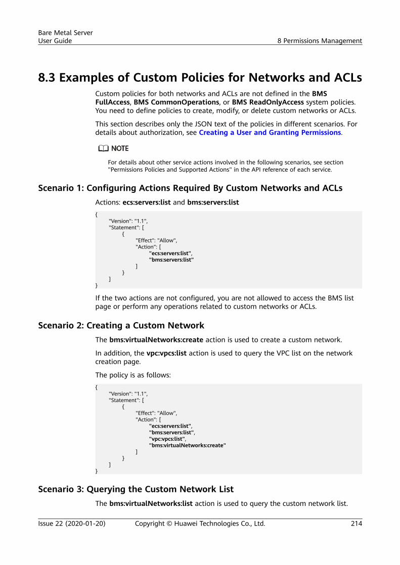
8.3 Examples of Custom Policies for Networks and ACLsCustom policies for both networks and ACLs are not defined in the BMSFullAccess, BMS CommonOperations, or BMS ReadOnlyAccess system policies.You need to define policies to create, modify, or delete custom networks or ACLs.
This section describes only the JSON text of the policies in different scenarios. Fordetails about authorization, see Creating a User and Granting Permissions.
For details about other service actions involved in the following scenarios, see section"Permissions Policies and Supported Actions" in the API reference of each service.
Scenario 1: Configuring Actions Required By Custom Networks and ACLsActions: ecs:servers:list and bms:servers:list
{ "Version": "1.1", "Statement": [ { "Effect": "Allow", "Action": [ "ecs:servers:list", "bms:servers:list" ] } ]}
If the two actions are not configured, you are not allowed to access the BMS listpage or perform any operations related to custom networks or ACLs.
Scenario 2: Creating a Custom NetworkThe bms:virtualNetworks:create action is used to create a custom network.
In addition, the vpc:vpcs:list action is used to query the VPC list on the networkcreation page.
The policy is as follows:
{ "Version": "1.1", "Statement": [ { "Effect": "Allow", "Action": [ "ecs:servers:list", "bms:servers:list", "vpc:vpcs:list", "bms:virtualNetworks:create" ] } ]}
Scenario 3: Querying the Custom Network ListThe bms:virtualNetworks:list action is used to query the custom network list.
Bare Metal ServerUser Guide 8 Permissions Management
Issue 22 (2020-01-20) Copyright © Huawei Technologies Co., Ltd. 214
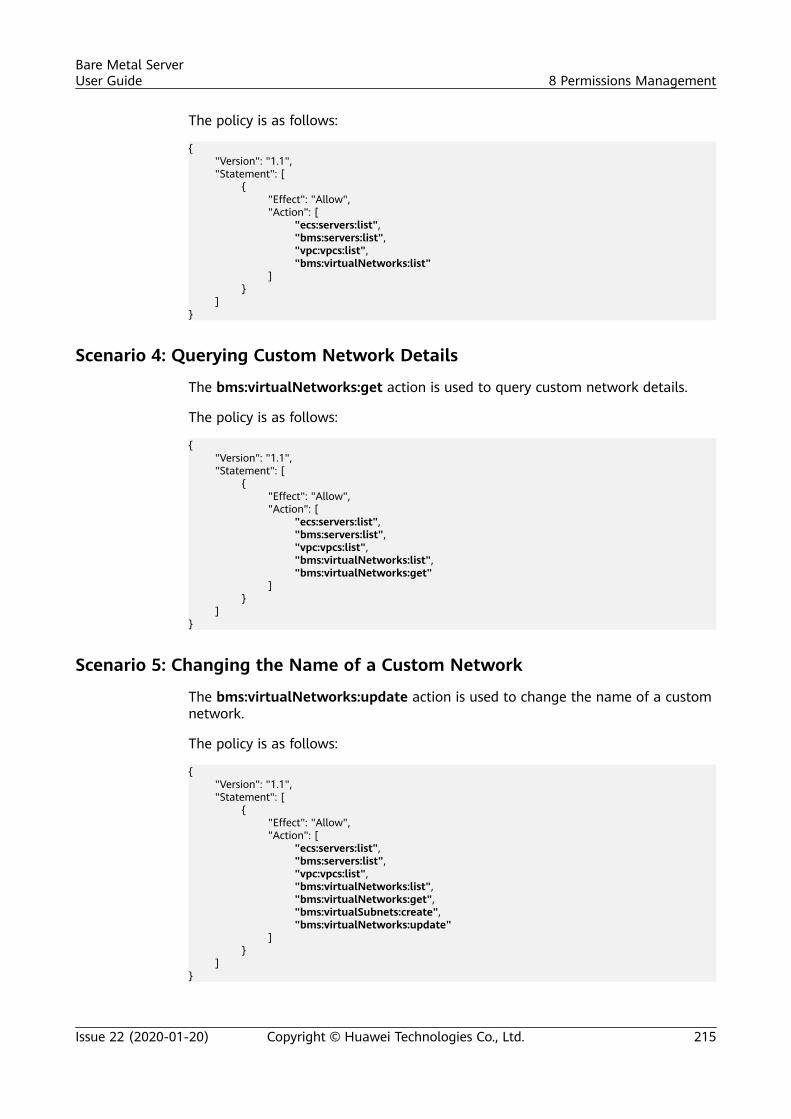
The policy is as follows:
{ "Version": "1.1", "Statement": [ { "Effect": "Allow", "Action": [ "ecs:servers:list", "bms:servers:list", "vpc:vpcs:list", "bms:virtualNetworks:list" ] } ]}
Scenario 4: Querying Custom Network Details
The bms:virtualNetworks:get action is used to query custom network details.
The policy is as follows:
{ "Version": "1.1", "Statement": [ { "Effect": "Allow", "Action": [ "ecs:servers:list", "bms:servers:list", "vpc:vpcs:list", "bms:virtualNetworks:list", "bms:virtualNetworks:get" ] } ]}
Scenario 5: Changing the Name of a Custom Network
The bms:virtualNetworks:update action is used to change the name of a customnetwork.
The policy is as follows:
{ "Version": "1.1", "Statement": [ { "Effect": "Allow", "Action": [ "ecs:servers:list", "bms:servers:list", "vpc:vpcs:list", "bms:virtualNetworks:list", "bms:virtualNetworks:get", "bms:virtualSubnets:create", "bms:virtualNetworks:update" ] } ]}
Bare Metal ServerUser Guide 8 Permissions Management
Issue 22 (2020-01-20) Copyright © Huawei Technologies Co., Ltd. 215
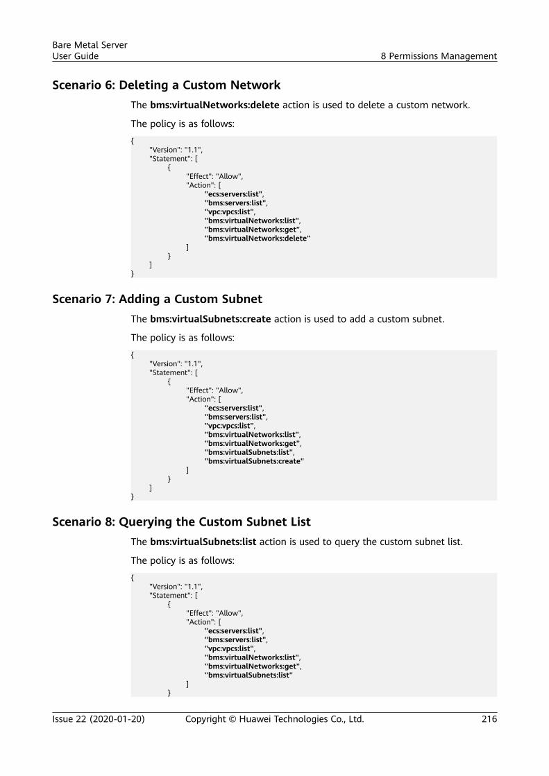
Scenario 6: Deleting a Custom NetworkThe bms:virtualNetworks:delete action is used to delete a custom network.
The policy is as follows:
{ "Version": "1.1", "Statement": [ { "Effect": "Allow", "Action": [ "ecs:servers:list", "bms:servers:list", "vpc:vpcs:list", "bms:virtualNetworks:list", "bms:virtualNetworks:get", "bms:virtualNetworks:delete" ] } ]}
Scenario 7: Adding a Custom SubnetThe bms:virtualSubnets:create action is used to add a custom subnet.
The policy is as follows:
{ "Version": "1.1", "Statement": [ { "Effect": "Allow", "Action": [ "ecs:servers:list", "bms:servers:list", "vpc:vpcs:list", "bms:virtualNetworks:list", "bms:virtualNetworks:get", "bms:virtualSubnets:list", "bms:virtualSubnets:create" ] } ]}
Scenario 8: Querying the Custom Subnet ListThe bms:virtualSubnets:list action is used to query the custom subnet list.
The policy is as follows:
{ "Version": "1.1", "Statement": [ { "Effect": "Allow", "Action": [ "ecs:servers:list", "bms:servers:list", "vpc:vpcs:list", "bms:virtualNetworks:list", "bms:virtualNetworks:get", "bms:virtualSubnets:list" ] }
Bare Metal ServerUser Guide 8 Permissions Management
Issue 22 (2020-01-20) Copyright © Huawei Technologies Co., Ltd. 216
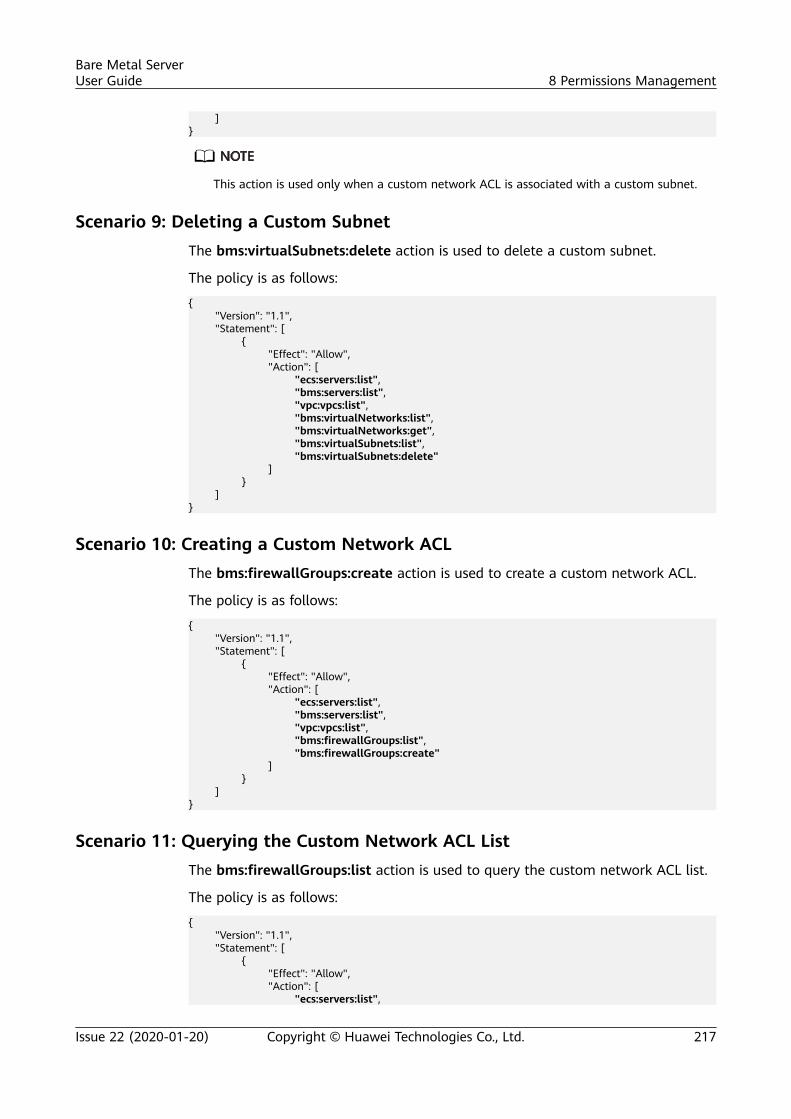
]}
This action is used only when a custom network ACL is associated with a custom subnet.
Scenario 9: Deleting a Custom SubnetThe bms:virtualSubnets:delete action is used to delete a custom subnet.
The policy is as follows:
{ "Version": "1.1", "Statement": [ { "Effect": "Allow", "Action": [ "ecs:servers:list", "bms:servers:list", "vpc:vpcs:list", "bms:virtualNetworks:list", "bms:virtualNetworks:get", "bms:virtualSubnets:list", "bms:virtualSubnets:delete" ] } ]}
Scenario 10: Creating a Custom Network ACLThe bms:firewallGroups:create action is used to create a custom network ACL.
The policy is as follows:
{ "Version": "1.1", "Statement": [ { "Effect": "Allow", "Action": [ "ecs:servers:list", "bms:servers:list", "vpc:vpcs:list", "bms:firewallGroups:list", "bms:firewallGroups:create" ] } ]}
Scenario 11: Querying the Custom Network ACL ListThe bms:firewallGroups:list action is used to query the custom network ACL list.
The policy is as follows:
{ "Version": "1.1", "Statement": [ { "Effect": "Allow", "Action": [ "ecs:servers:list",
Bare Metal ServerUser Guide 8 Permissions Management
Issue 22 (2020-01-20) Copyright © Huawei Technologies Co., Ltd. 217
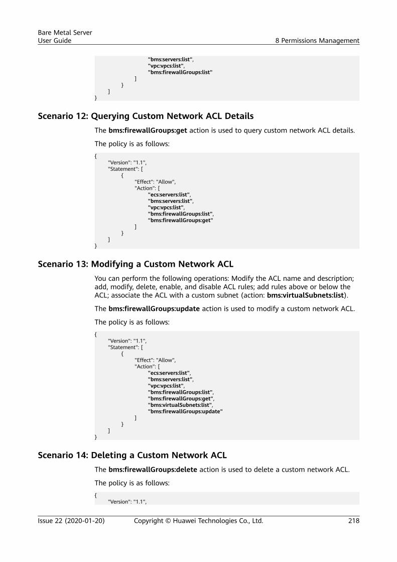
"bms:servers:list", "vpc:vpcs:list", "bms:firewallGroups:list" ] } ]}
Scenario 12: Querying Custom Network ACL DetailsThe bms:firewallGroups:get action is used to query custom network ACL details.
The policy is as follows:
{ "Version": "1.1", "Statement": [ { "Effect": "Allow", "Action": [ "ecs:servers:list", "bms:servers:list", "vpc:vpcs:list", "bms:firewallGroups:list", "bms:firewallGroups:get" ] } ]}
Scenario 13: Modifying a Custom Network ACLYou can perform the following operations: Modify the ACL name and description;add, modify, delete, enable, and disable ACL rules; add rules above or below theACL; associate the ACL with a custom subnet (action: bms:virtualSubnets:list).
The bms:firewallGroups:update action is used to modify a custom network ACL.
The policy is as follows:
{ "Version": "1.1", "Statement": [ { "Effect": "Allow", "Action": [ "ecs:servers:list", "bms:servers:list", "vpc:vpcs:list", "bms:firewallGroups:list", "bms:firewallGroups:get", "bms:virtualSubnets:list", "bms:firewallGroups:update" ] } ]}
Scenario 14: Deleting a Custom Network ACLThe bms:firewallGroups:delete action is used to delete a custom network ACL.
The policy is as follows:
{ "Version": "1.1",
Bare Metal ServerUser Guide 8 Permissions Management
Issue 22 (2020-01-20) Copyright © Huawei Technologies Co., Ltd. 218

"Statement": [ { "Effect": "Allow", "Action": [ "ecs:servers:list", "bms:servers:list", "vpc:vpcs:list", "bms:firewallGroups:list", "bms:firewallGroups:get", "bms:firewallGroups:delete" ] } ]}
Bare Metal ServerUser Guide 8 Permissions Management
Issue 22 (2020-01-20) Copyright © Huawei Technologies Co., Ltd. 219
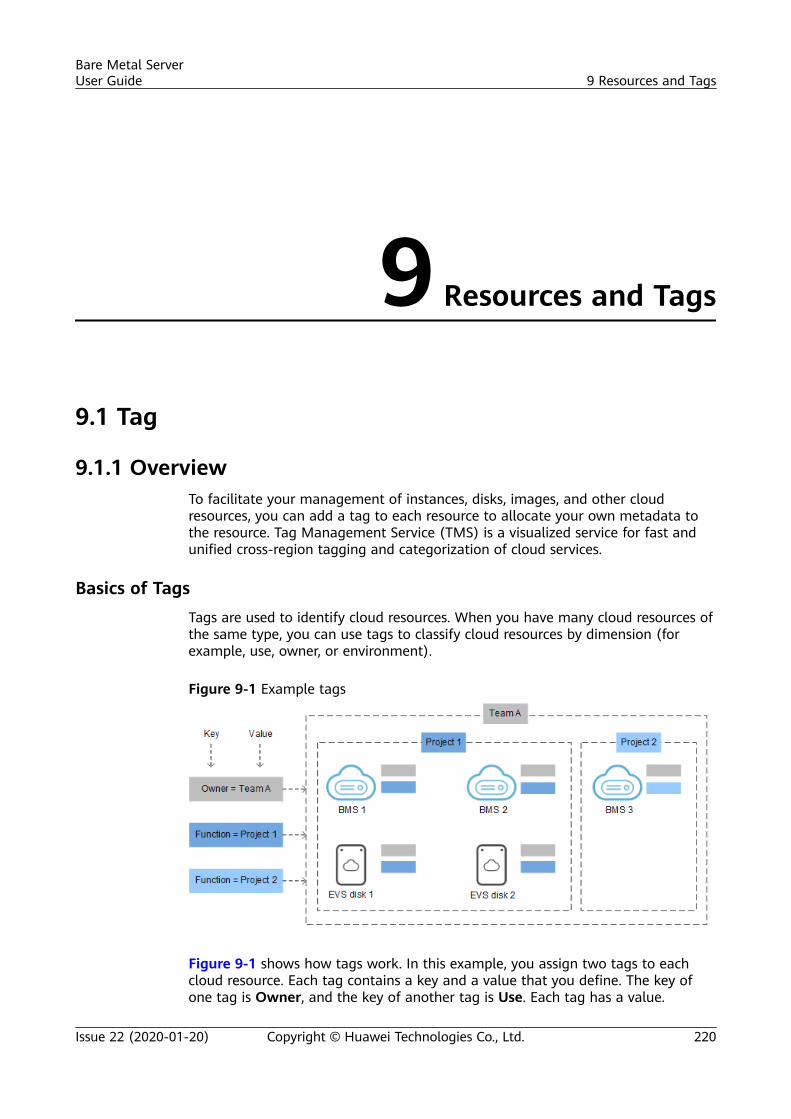
9 Resources and Tags
9.1 Tag
9.1.1 OverviewTo facilitate your management of instances, disks, images, and other cloudresources, you can add a tag to each resource to allocate your own metadata tothe resource. Tag Management Service (TMS) is a visualized service for fast andunified cross-region tagging and categorization of cloud services.
Basics of TagsTags are used to identify cloud resources. When you have many cloud resources ofthe same type, you can use tags to classify cloud resources by dimension (forexample, use, owner, or environment).
Figure 9-1 Example tags
Figure 9-1 shows how tags work. In this example, you assign two tags to eachcloud resource. Each tag contains a key and a value that you define. The key ofone tag is Owner, and the key of another tag is Use. Each tag has a value.
Bare Metal ServerUser Guide 9 Resources and Tags
Issue 22 (2020-01-20) Copyright © Huawei Technologies Co., Ltd. 220
You can quickly search for and filter specific cloud resources based on the tagsadded to them. For example, you can define a set of tags for cloud resources in anaccount to track the owner and usage of each cloud resource, making resourcemanagement easier.
Tag Usage● BMS-related services that support tags include ECS, IMS, and EVS.● Each tag consists of a key and a value.● A BMS can have a maximum of nine tags.● For each resource, each tag key must be unique and can have only one tag
value.● Table 9-1 provides the tag key and value requirements.
Table 9-1 Tag key and value requirements
Parameter Requirement Example Value
Tag key ● Cannot be left blank.● Can only contain letters, digits,
underscores (_), and hyphens (-).● Contains a maximum of 36
characters.
Organization
Tag value ● Cannot be left blank.● Can only contain letters, digits,
underscores (_), periods (.), andhyphens (-).
● Contains a maximum of 43characters.
Apache
9.1.2 Adding TagsTags are used to identify cloud resources, such as instances, images, and disks. Ifyou have multiple types of cloud resources which are associated with each other,you can add tags to the resources to classify and manage them easily. For moreinformation, see Overview.
You can add tags to a BMS in either of the following ways:
● Add Tags During BMS Creation● Add Tags on the BMS Details Page
Add Tags During BMS Creation1. Log in to the management console.2. Under Computing, click Bare Metal Server.3. Click Buy BMS.4. Configure the BMS parameters.
Bare Metal ServerUser Guide 9 Resources and Tags
Issue 22 (2020-01-20) Copyright © Huawei Technologies Co., Ltd. 221
Select Configure now for Advanced Settings and add a tag key and tagvalue. For the tag key and tag value requirements, see Table 9-1.
For details about other parameters, see Creating a BMS.
Add Tags on the BMS Details Page1. Log in to the management console.2. Under Computing, click Bare Metal Server.3. In the BMS list, click the name of the target BMS.
The page showing details of the BMS is displayed.4. Click the Tags tab and then Add Tag. In the displayed dialog box, enter the
tag key and tag value. For the tag key and tag value requirements, see Table9-1.You can change the tag value after the tag is added.
Tips
If you want to add the same tag to multiple BMSs or other resources, you cancreate a predefined tag on the TMS console and then select the tag for the BMSsor resources. This free you from having to repeatedly enter tag keys and values.The procedure is as follows:
1. Log in to the management console.2. In the upper right corner of the page, click the username and select Tag
Management from the drop-down list.3. In the navigation pane on the left, choose Predefined Tags. In the right pane,
click Create Tag, and enter a key (for example project) and a value (forexample A) in the displayed dialog box.
4. Choose Service List > Computing > Bare Metal Server. On the BMS console,click the name of the BMS to which you want to add the predefined tag.The page showing details of the BMS is displayed.
5. Click the Tags tab and then Add Tag. In the displayed dialog box, select thepredefined tag you have created.
9.1.3 Searching for Resources by TagAfter tags are added to resources, you can search for resources by tag using eitherof the following methods.
Filter Resources in the Resource List
On the BMS console, query BMSs by tag key and value.
1. Log in to the management console.2. Under Computing, click Bare Metal Server.3. Click Search by Tag above the upper right corner of the BMS list to expand
the search area.
Bare Metal ServerUser Guide 9 Resources and Tags
Issue 22 (2020-01-20) Copyright © Huawei Technologies Co., Ltd. 222
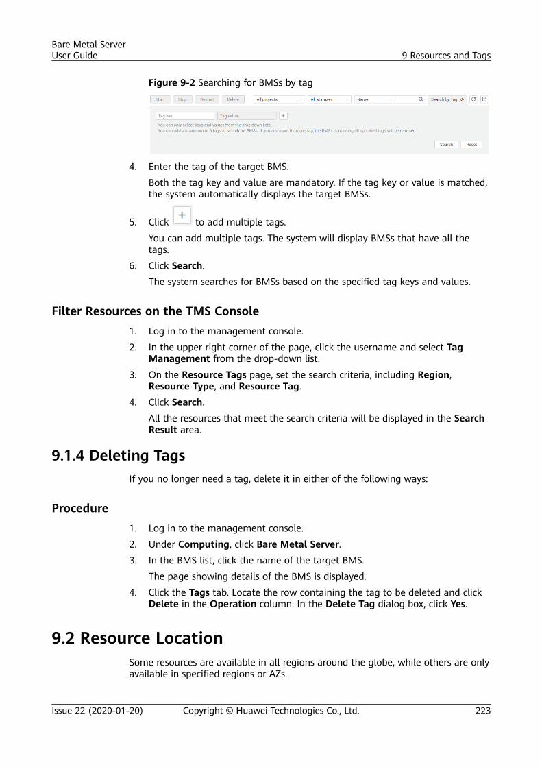
Figure 9-2 Searching for BMSs by tag
4. Enter the tag of the target BMS.
Both the tag key and value are mandatory. If the tag key or value is matched,the system automatically displays the target BMSs.
5. Click to add multiple tags.
You can add multiple tags. The system will display BMSs that have all thetags.
6. Click Search.
The system searches for BMSs based on the specified tag keys and values.
Filter Resources on the TMS Console1. Log in to the management console.
2. In the upper right corner of the page, click the username and select TagManagement from the drop-down list.
3. On the Resource Tags page, set the search criteria, including Region,Resource Type, and Resource Tag.
4. Click Search.
All the resources that meet the search criteria will be displayed in the SearchResult area.
9.1.4 Deleting TagsIf you no longer need a tag, delete it in either of the following ways:
Procedure1. Log in to the management console.
2. Under Computing, click Bare Metal Server.
3. In the BMS list, click the name of the target BMS.
The page showing details of the BMS is displayed.
4. Click the Tags tab. Locate the row containing the tag to be deleted and clickDelete in the Operation column. In the Delete Tag dialog box, click Yes.
9.2 Resource LocationSome resources are available in all regions around the globe, while others are onlyavailable in specified regions or AZs.
Bare Metal ServerUser Guide 9 Resources and Tags
Issue 22 (2020-01-20) Copyright © Huawei Technologies Co., Ltd. 223
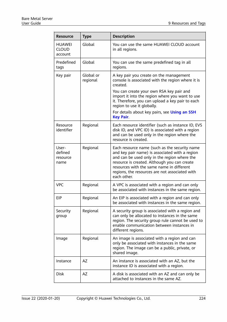
Resource Type Description
HUAWEICLOUDaccount
Global You can use the same HUAWEI CLOUD accountin all regions.
Predefinedtags
Global You can use the same predefined tag in allregions.
Key pair Global orregional
A key pair you create on the managementconsole is associated with the region where it iscreated.You can create your own RSA key pair andimport it into the region where you want to useit. Therefore, you can upload a key pair to eachregion to use it globally.For details about key pairs, see Using an SSHKey Pair.
Resourceidentifier
Regional Each resource identifier (such as instance ID, EVSdisk ID, and VPC ID) is associated with a regionand can be used only in the region where theresource is created.
User-definedresourcename
Regional Each resource name (such as the security nameand key pair name) is associated with a regionand can be used only in the region where theresource is created. Although you can createresources with the same name in differentregions, the resources are not associated witheach other.
VPC Regional A VPC is associated with a region and can onlybe associated with instances in the same region.
EIP Regional An EIP is associated with a region and can onlybe associated with instances in the same region.
Securitygroup
Regional A security group is associated with a region andcan only be allocated to instances in the sameregion. The security group rule cannot be used toenable communication between instances indifferent regions.
Image Regional An image is associated with a region and canonly be associated with instances in the sameregion. The image can be a public, private, orshared image.
Instance AZ An instance is associated with an AZ, but theinstance ID is associated with a region.
Disk AZ A disk is associated with an AZ and can only beattached to instances in the same AZ.
Bare Metal ServerUser Guide 9 Resources and Tags
Issue 22 (2020-01-20) Copyright © Huawei Technologies Co., Ltd. 224
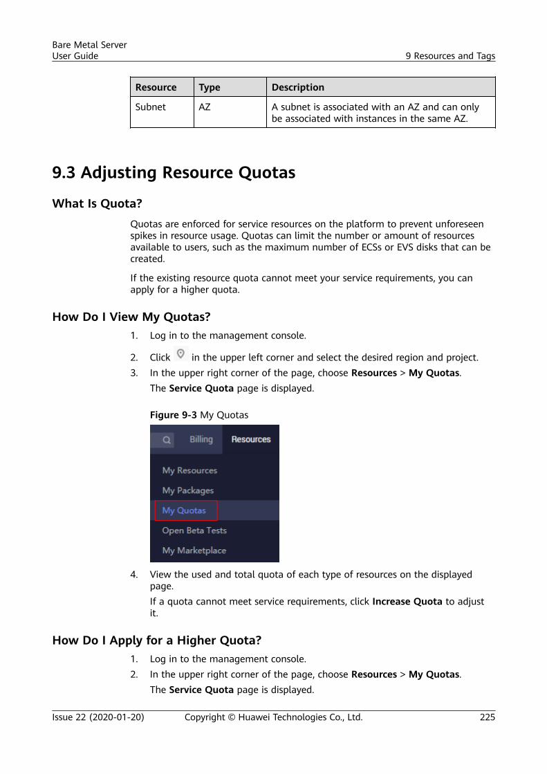
Resource Type Description
Subnet AZ A subnet is associated with an AZ and can onlybe associated with instances in the same AZ.
9.3 Adjusting Resource Quotas
What Is Quota?Quotas are enforced for service resources on the platform to prevent unforeseenspikes in resource usage. Quotas can limit the number or amount of resourcesavailable to users, such as the maximum number of ECSs or EVS disks that can becreated.
If the existing resource quota cannot meet your service requirements, you canapply for a higher quota.
How Do I View My Quotas?1. Log in to the management console.
2. Click in the upper left corner and select the desired region and project.3. In the upper right corner of the page, choose Resources > My Quotas.
The Service Quota page is displayed.
Figure 9-3 My Quotas
4. View the used and total quota of each type of resources on the displayedpage.If a quota cannot meet service requirements, click Increase Quota to adjustit.
How Do I Apply for a Higher Quota?1. Log in to the management console.2. In the upper right corner of the page, choose Resources > My Quotas.
The Service Quota page is displayed.
Bare Metal ServerUser Guide 9 Resources and Tags
Issue 22 (2020-01-20) Copyright © Huawei Technologies Co., Ltd. 225
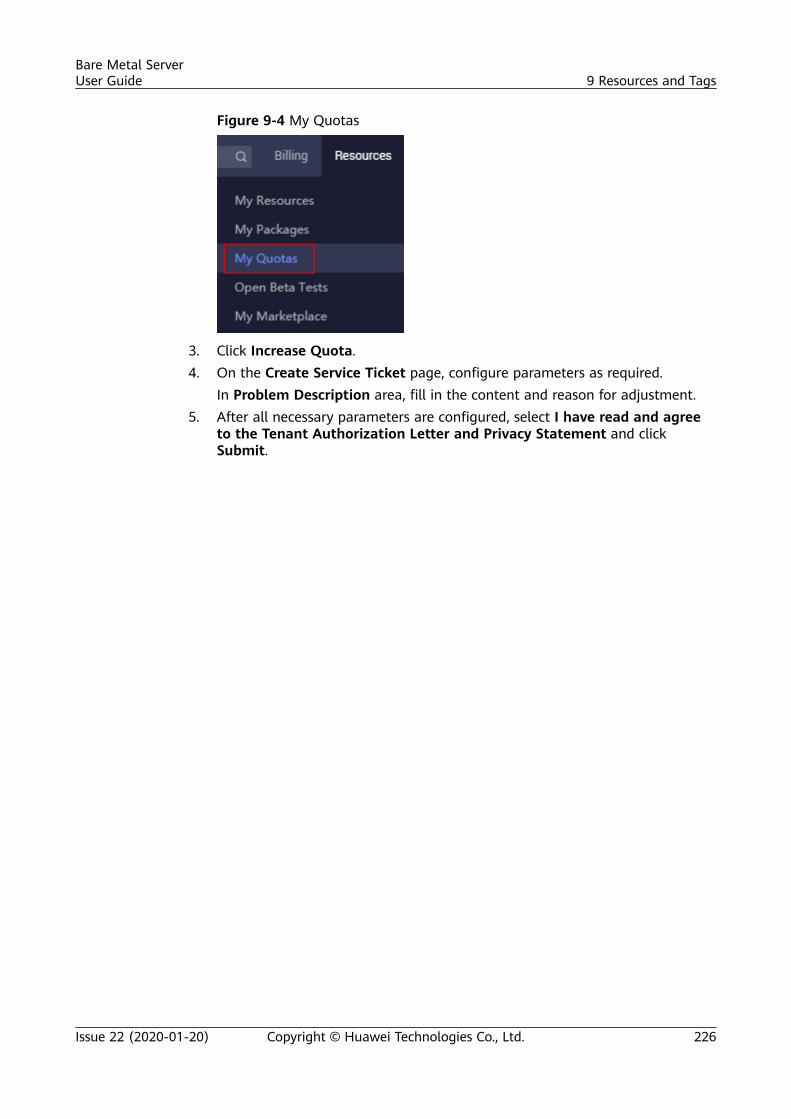
Figure 9-4 My Quotas
3. Click Increase Quota.4. On the Create Service Ticket page, configure parameters as required.
In Problem Description area, fill in the content and reason for adjustment.5. After all necessary parameters are configured, select I have read and agree
to the Tenant Authorization Letter and Privacy Statement and clickSubmit.
Bare Metal ServerUser Guide 9 Resources and Tags
Issue 22 (2020-01-20) Copyright © Huawei Technologies Co., Ltd. 226
10 Server Monitoring
10.1 Overview
Server Monitoring
Server monitoring provided by Cloud Eye includes basic monitoring and OSmonitoring. Basic monitoring refers to monitoring of ECS metrics automaticallyreported (BMS does not support basic monitoring). OS monitoring providessystem-wide, active, and fine-grained (10-second interval) monitoring for BMSs,on which Agent is installed. Agent occupies less than 1.5% CPU and less than 50MB memory of the OS.
To meet the basic monitoring and O&M requirements for servers, ServerMonitoring monitors more than 40 metrics, such as CPU, memory, disk, andnetwork metrics.
Constraints● Agent can only be installed on BMSs running a 64-bit Linux OS.
● Only CN North-Beijing1 (cn-north-1), CN South-Guangzhou (cn-south-1),CN East-Shanghai2 (cn-east-2), and Asia Pacific-Hong Kong (ap-southeast-1) are supported now.
● Private images do not support this function.
Table 10-1 lists the Linux images that support server monitoring.
Table 10-1 Linux images that support server monitoring
OS Type (64-bit) Version
SUSE Enterprise11 SP4 and Enterprise12SP1
CentOS 6.9 and 7.3
EulerOS 2.2
Bare Metal ServerUser Guide 10 Server Monitoring
Issue 22 (2020-01-20) Copyright © Huawei Technologies Co., Ltd. 227
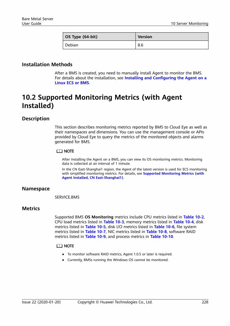
OS Type (64-bit) Version
Debian 8.6
Installation MethodsAfter a BMS is created, you need to manually install Agent to monitor the BMS.For details about the installation, see Installing and Configuring the Agent on aLinux ECS or BMS.
10.2 Supported Monitoring Metrics (with AgentInstalled)
DescriptionThis section describes monitoring metrics reported by BMS to Cloud Eye as well astheir namespaces and dimensions. You can use the management console or APIsprovided by Cloud Eye to query the metrics of the monitored objects and alarmsgenerated for BMS.
After installing the Agent on a BMS, you can view its OS monitoring metrics. Monitoringdata is collected at an interval of 1 minute.In the CN East-Shanghai1 region, the Agent of the latest version is used for ECS monitoringwith simplified monitoring metrics. For details, see Supported Monitoring Metrics (withAgent Installed, CN East-Shanghai1).
NamespaceSERVICE.BMS
MetricsSupported BMS OS Monitoring metrics include CPU metrics listed in Table 10-2,CPU load metrics listed in Table 10-3, memory metrics listed in Table 10-4, diskmetrics listed in Table 10-5, disk I/O metrics listed in Table 10-6, file systemmetrics listed in Table 10-7, NIC metrics listed in Table 10-8, software RAIDmetrics listed in Table 10-9, and process metrics in Table 10-10.
● To monitor software RAID metrics, Agent 1.0.5 or later is required.● Currently, BMSs running the Windows OS cannot be monitored.
Bare Metal ServerUser Guide 10 Server Monitoring
Issue 22 (2020-01-20) Copyright © Huawei Technologies Co., Ltd. 228
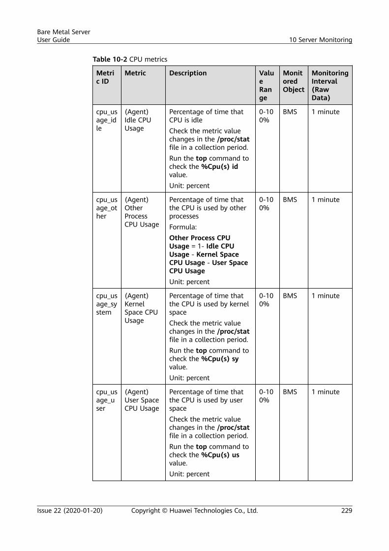
Table 10-2 CPU metrics
Metric ID
Metric Description ValueRange
MonitoredObject
MonitoringInterval(RawData)
cpu_usage_idle
(Agent)Idle CPUUsage
Percentage of time thatCPU is idleCheck the metric valuechanges in the /proc/statfile in a collection period.Run the top command tocheck the %Cpu(s) idvalue.Unit: percent
0-100%
BMS 1 minute
cpu_usage_other
(Agent)OtherProcessCPU Usage
Percentage of time thatthe CPU is used by otherprocessesFormula:Other Process CPUUsage = 1- Idle CPUUsage - Kernel SpaceCPU Usage - User SpaceCPU UsageUnit: percent
0-100%
BMS 1 minute
cpu_usage_system
(Agent)KernelSpace CPUUsage
Percentage of time thatthe CPU is used by kernelspaceCheck the metric valuechanges in the /proc/statfile in a collection period.Run the top command tocheck the %Cpu(s) syvalue.Unit: percent
0-100%
BMS 1 minute
cpu_usage_user
(Agent)User SpaceCPU Usage
Percentage of time thatthe CPU is used by userspaceCheck the metric valuechanges in the /proc/statfile in a collection period.Run the top command tocheck the %Cpu(s) usvalue.Unit: percent
0-100%
BMS 1 minute
Bare Metal ServerUser Guide 10 Server Monitoring
Issue 22 (2020-01-20) Copyright © Huawei Technologies Co., Ltd. 229
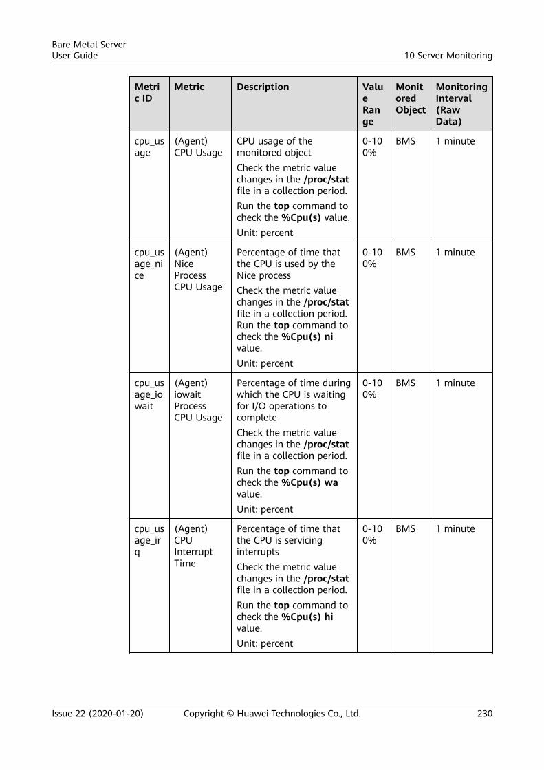
Metric ID
Metric Description ValueRange
MonitoredObject
MonitoringInterval(RawData)
cpu_usage
(Agent)CPU Usage
CPU usage of themonitored objectCheck the metric valuechanges in the /proc/statfile in a collection period.Run the top command tocheck the %Cpu(s) value.Unit: percent
0-100%
BMS 1 minute
cpu_usage_nice
(Agent)NiceProcessCPU Usage
Percentage of time thatthe CPU is used by theNice processCheck the metric valuechanges in the /proc/statfile in a collection period.Run the top command tocheck the %Cpu(s) nivalue.Unit: percent
0-100%
BMS 1 minute
cpu_usage_iowait
(Agent)iowaitProcessCPU Usage
Percentage of time duringwhich the CPU is waitingfor I/O operations tocompleteCheck the metric valuechanges in the /proc/statfile in a collection period.Run the top command tocheck the %Cpu(s) wavalue.Unit: percent
0-100%
BMS 1 minute
cpu_usage_irq
(Agent)CPUInterruptTime
Percentage of time thatthe CPU is servicinginterruptsCheck the metric valuechanges in the /proc/statfile in a collection period.Run the top command tocheck the %Cpu(s) hivalue.Unit: percent
0-100%
BMS 1 minute
Bare Metal ServerUser Guide 10 Server Monitoring
Issue 22 (2020-01-20) Copyright © Huawei Technologies Co., Ltd. 230
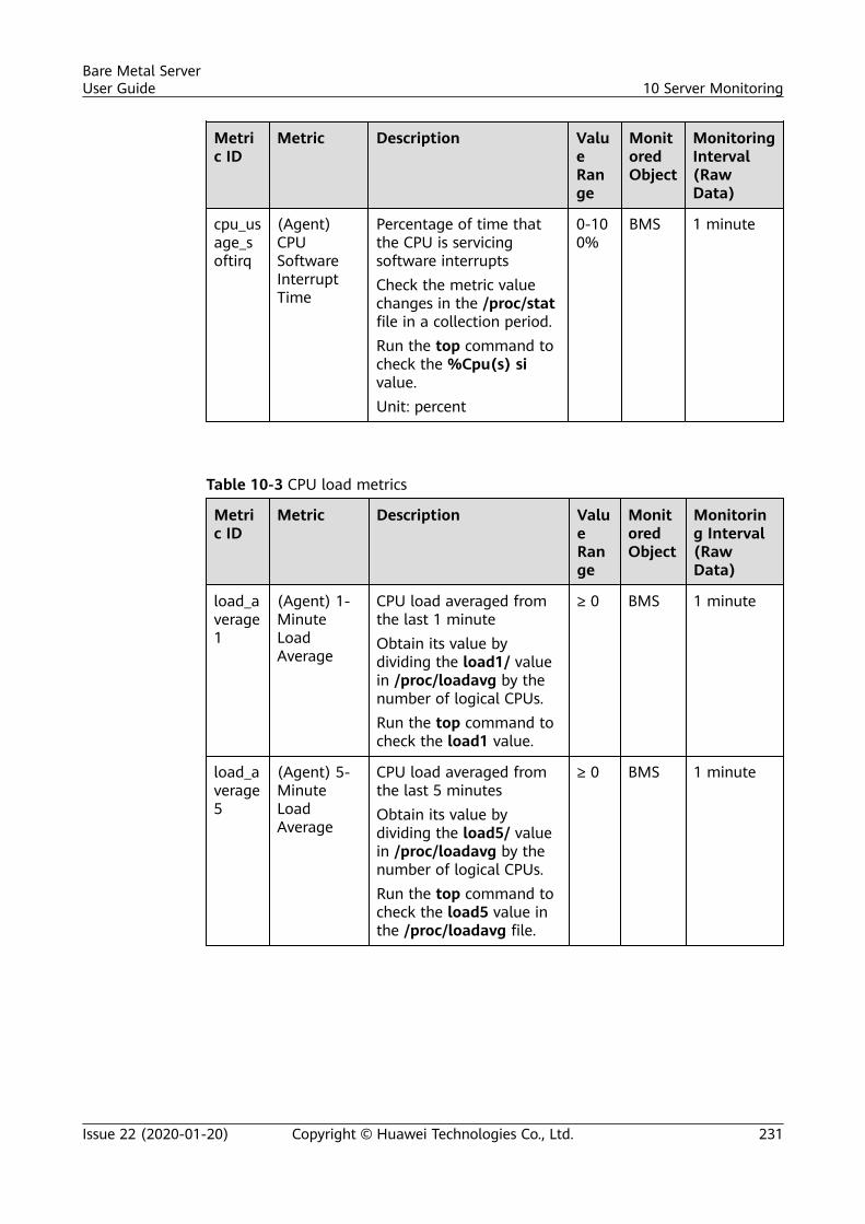
Metric ID
Metric Description ValueRange
MonitoredObject
MonitoringInterval(RawData)
cpu_usage_softirq
(Agent)CPUSoftwareInterruptTime
Percentage of time thatthe CPU is servicingsoftware interruptsCheck the metric valuechanges in the /proc/statfile in a collection period.Run the top command tocheck the %Cpu(s) sivalue.Unit: percent
0-100%
BMS 1 minute
Table 10-3 CPU load metrics
Metric ID
Metric Description ValueRange
MonitoredObject
Monitoring Interval(RawData)
load_average1
(Agent) 1-MinuteLoadAverage
CPU load averaged fromthe last 1 minuteObtain its value bydividing the load1/ valuein /proc/loadavg by thenumber of logical CPUs.Run the top command tocheck the load1 value.
≥ 0 BMS 1 minute
load_average5
(Agent) 5-MinuteLoadAverage
CPU load averaged fromthe last 5 minutesObtain its value bydividing the load5/ valuein /proc/loadavg by thenumber of logical CPUs.Run the top command tocheck the load5 value inthe /proc/loadavg file.
≥ 0 BMS 1 minute
Bare Metal ServerUser Guide 10 Server Monitoring
Issue 22 (2020-01-20) Copyright © Huawei Technologies Co., Ltd. 231
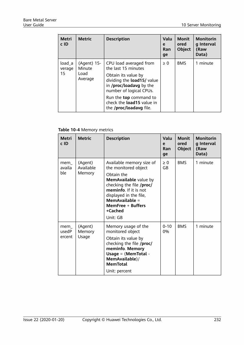
Metric ID
Metric Description ValueRange
MonitoredObject
Monitoring Interval(RawData)
load_average15
(Agent) 15-MinuteLoadAverage
CPU load averaged fromthe last 15 minutesObtain its value bydividing the load15/ valuein /proc/loadavg by thenumber of logical CPUs.Run the top command tocheck the load15 value inthe /proc/loadavg file.
≥ 0 BMS 1 minute
Table 10-4 Memory metrics
Metric ID
Metric Description ValueRange
MonitoredObject
Monitoring Interval(RawData)
mem_available
(Agent)AvailableMemory
Available memory size ofthe monitored objectObtain theMemAvailable value bychecking the file /proc/meminfo. If it is notdisplayed in the file,MemAvailable =MemFree + Buffers+CachedUnit: GB
≥ 0GB
BMS 1 minute
mem_usedPercent
(Agent)MemoryUsage
Memory usage of themonitored objectObtain its value bychecking the file /proc/meminfo. MemoryUsage = (MemTotal -MemAvailable)/MemTotalUnit: percent
0-100%
BMS 1 minute
Bare Metal ServerUser Guide 10 Server Monitoring
Issue 22 (2020-01-20) Copyright © Huawei Technologies Co., Ltd. 232
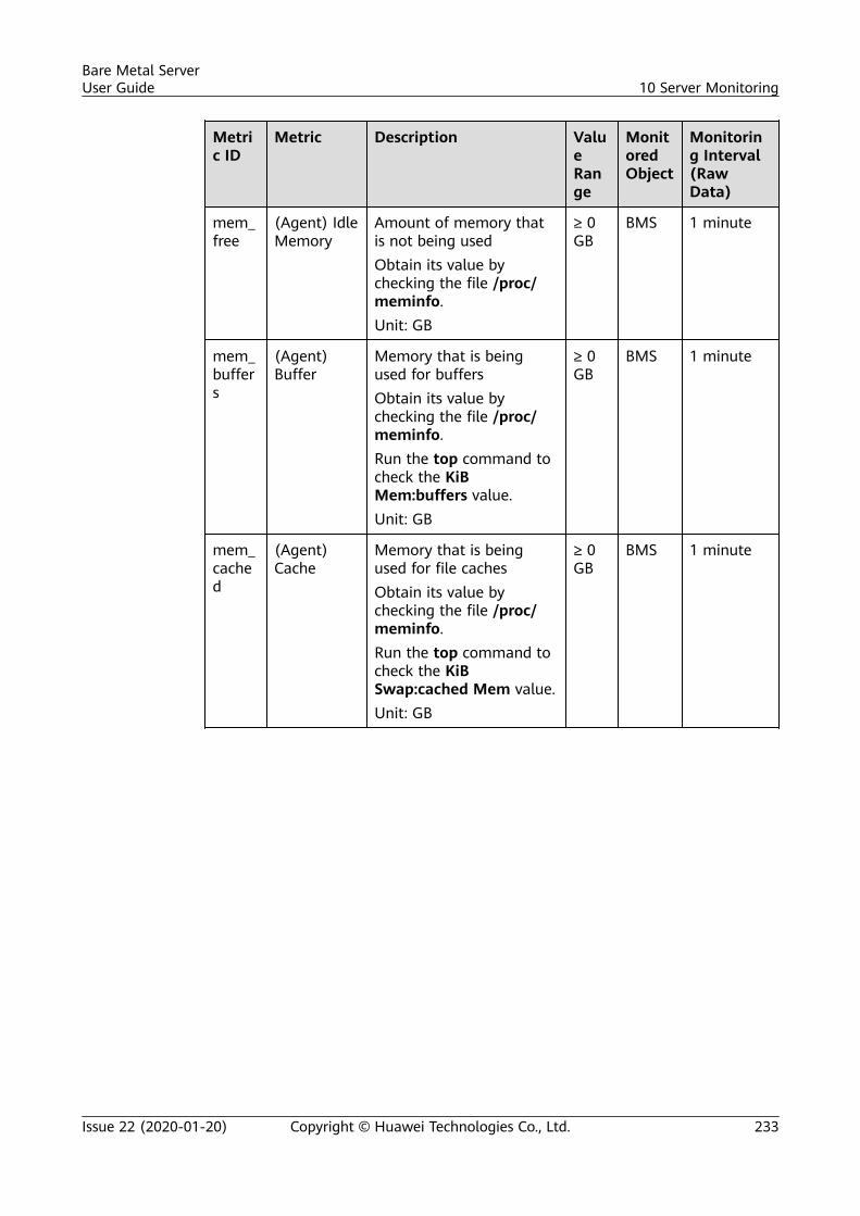
Metric ID
Metric Description ValueRange
MonitoredObject
Monitoring Interval(RawData)
mem_free
(Agent) IdleMemory
Amount of memory thatis not being usedObtain its value bychecking the file /proc/meminfo.Unit: GB
≥ 0GB
BMS 1 minute
mem_buffers
(Agent)Buffer
Memory that is beingused for buffersObtain its value bychecking the file /proc/meminfo.Run the top command tocheck the KiBMem:buffers value.Unit: GB
≥ 0GB
BMS 1 minute
mem_cached
(Agent)Cache
Memory that is beingused for file cachesObtain its value bychecking the file /proc/meminfo.Run the top command tocheck the KiBSwap:cached Mem value.Unit: GB
≥ 0GB
BMS 1 minute
Bare Metal ServerUser Guide 10 Server Monitoring
Issue 22 (2020-01-20) Copyright © Huawei Technologies Co., Ltd. 233
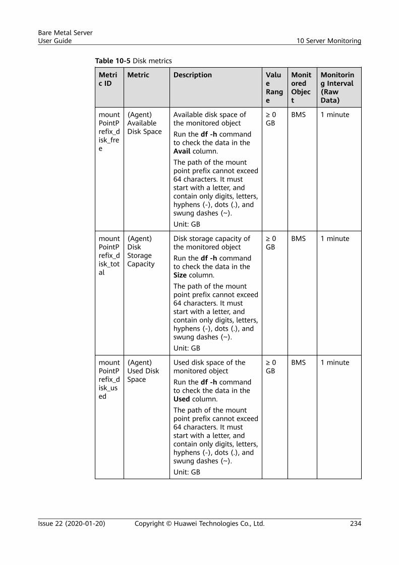
Table 10-5 Disk metrics
Metric ID
Metric Description ValueRange
MonitoredObject
Monitoring Interval(RawData)
mountPointPrefix_disk_free
(Agent)AvailableDisk Space
Available disk space ofthe monitored objectRun the df -h commandto check the data in theAvail column.The path of the mountpoint prefix cannot exceed64 characters. It muststart with a letter, andcontain only digits, letters,hyphens (-), dots (.), andswung dashes (~).Unit: GB
≥ 0GB
BMS 1 minute
mountPointPrefix_disk_total
(Agent)DiskStorageCapacity
Disk storage capacity ofthe monitored objectRun the df -h commandto check the data in theSize column.The path of the mountpoint prefix cannot exceed64 characters. It muststart with a letter, andcontain only digits, letters,hyphens (-), dots (.), andswung dashes (~).Unit: GB
≥ 0GB
BMS 1 minute
mountPointPrefix_disk_used
(Agent)Used DiskSpace
Used disk space of themonitored objectRun the df -h commandto check the data in theUsed column.The path of the mountpoint prefix cannot exceed64 characters. It muststart with a letter, andcontain only digits, letters,hyphens (-), dots (.), andswung dashes (~).Unit: GB
≥ 0GB
BMS 1 minute
Bare Metal ServerUser Guide 10 Server Monitoring
Issue 22 (2020-01-20) Copyright © Huawei Technologies Co., Ltd. 234
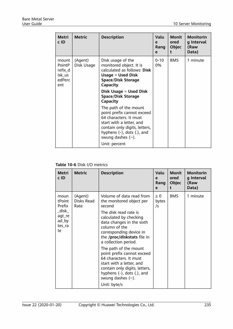
Metric ID
Metric Description ValueRange
MonitoredObject
Monitoring Interval(RawData)
mountPointPrefix_disk_usedPercent
(Agent)Disk Usage
Disk usage of themonitored object. It iscalculated as follows: DiskUsage = Used DiskSpace/Disk StorageCapacity.Disk Usage = Used DiskSpace/Disk StorageCapacityThe path of the mountpoint prefix cannot exceed64 characters. It muststart with a letter, andcontain only digits, letters,hyphens (-), dots (.), andswung dashes (~).Unit: percent
0-100%
BMS 1 minute
Table 10-6 Disk I/O metrics
Metric ID
Metric Description ValueRange
MonitoredObject
Monitoring Interval(RawData)
mountPointPrefix_disk_agt_read_bytes_rate
(Agent)Disks ReadRate
Volume of data read fromthe monitored object persecondThe disk read rate iscalculated by checkingdata changes in the sixthcolumn of thecorresponding device inthe /proc/diskstats file ina collection period.The path of the mountpoint prefix cannot exceed64 characters. It muststart with a letter, andcontain only digits, letters,hyphens (-), dots (.), andswung dashes (~).Unit: byte/s
≥ 0bytes/s
BMS 1 minute
Bare Metal ServerUser Guide 10 Server Monitoring
Issue 22 (2020-01-20) Copyright © Huawei Technologies Co., Ltd. 235
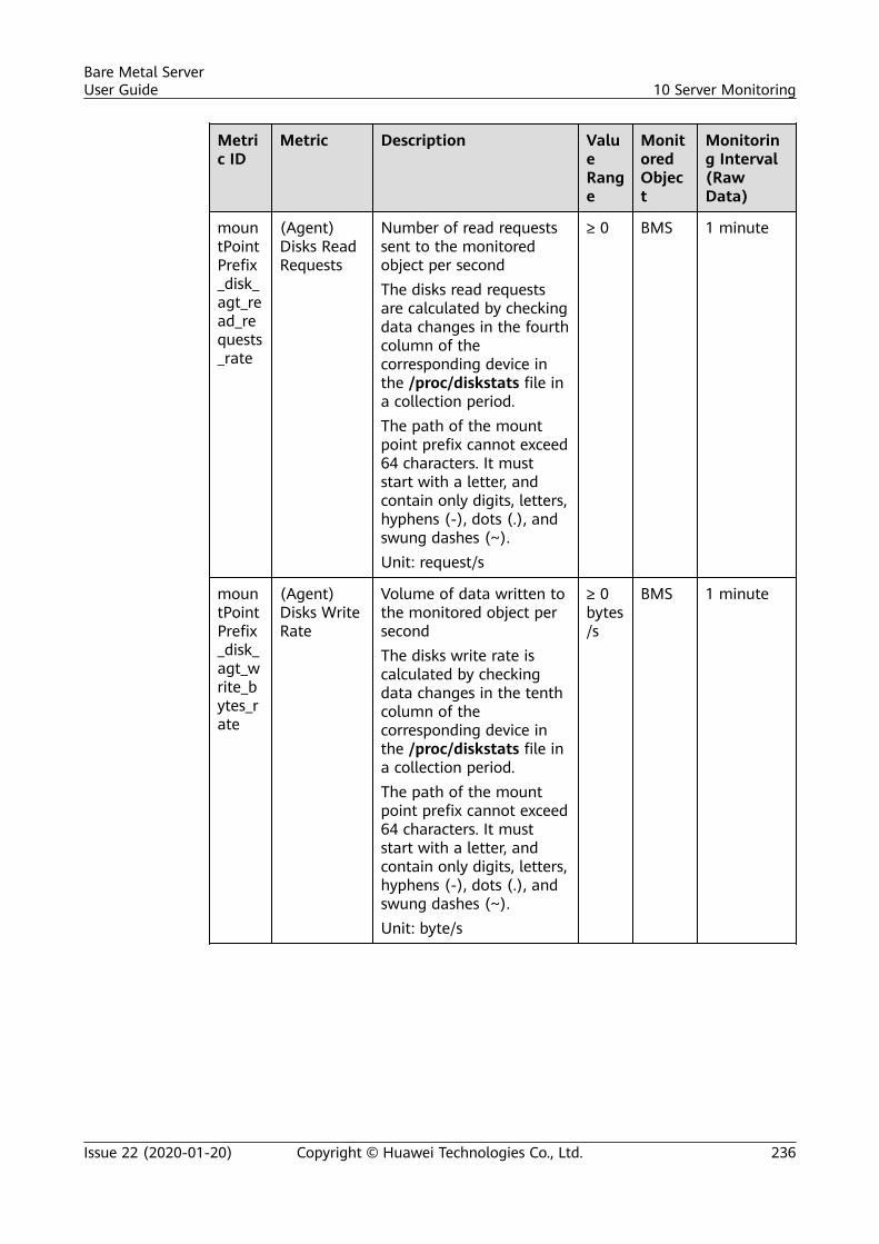
Metric ID
Metric Description ValueRange
MonitoredObject
Monitoring Interval(RawData)
mountPointPrefix_disk_agt_read_requests_rate
(Agent)Disks ReadRequests
Number of read requestssent to the monitoredobject per secondThe disks read requestsare calculated by checkingdata changes in the fourthcolumn of thecorresponding device inthe /proc/diskstats file ina collection period.The path of the mountpoint prefix cannot exceed64 characters. It muststart with a letter, andcontain only digits, letters,hyphens (-), dots (.), andswung dashes (~).Unit: request/s
≥ 0 BMS 1 minute
mountPointPrefix_disk_agt_write_bytes_rate
(Agent)Disks WriteRate
Volume of data written tothe monitored object persecondThe disks write rate iscalculated by checkingdata changes in the tenthcolumn of thecorresponding device inthe /proc/diskstats file ina collection period.The path of the mountpoint prefix cannot exceed64 characters. It muststart with a letter, andcontain only digits, letters,hyphens (-), dots (.), andswung dashes (~).Unit: byte/s
≥ 0bytes/s
BMS 1 minute
Bare Metal ServerUser Guide 10 Server Monitoring
Issue 22 (2020-01-20) Copyright © Huawei Technologies Co., Ltd. 236
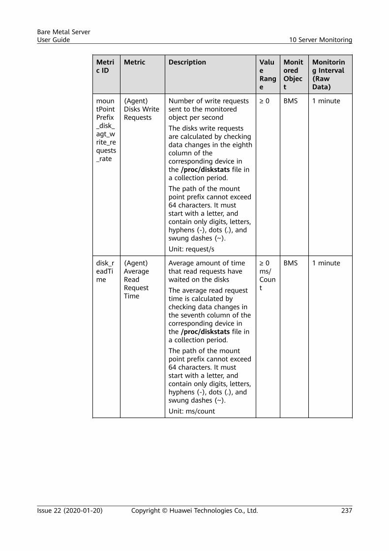
Metric ID
Metric Description ValueRange
MonitoredObject
Monitoring Interval(RawData)
mountPointPrefix_disk_agt_write_requests_rate
(Agent)Disks WriteRequests
Number of write requestssent to the monitoredobject per secondThe disks write requestsare calculated by checkingdata changes in the eighthcolumn of thecorresponding device inthe /proc/diskstats file ina collection period.The path of the mountpoint prefix cannot exceed64 characters. It muststart with a letter, andcontain only digits, letters,hyphens (-), dots (.), andswung dashes (~).Unit: request/s
≥ 0 BMS 1 minute
disk_readTime
(Agent)AverageReadRequestTime
Average amount of timethat read requests havewaited on the disksThe average read requesttime is calculated bychecking data changes inthe seventh column of thecorresponding device inthe /proc/diskstats file ina collection period.The path of the mountpoint prefix cannot exceed64 characters. It muststart with a letter, andcontain only digits, letters,hyphens (-), dots (.), andswung dashes (~).Unit: ms/count
≥ 0ms/Count
BMS 1 minute
Bare Metal ServerUser Guide 10 Server Monitoring
Issue 22 (2020-01-20) Copyright © Huawei Technologies Co., Ltd. 237
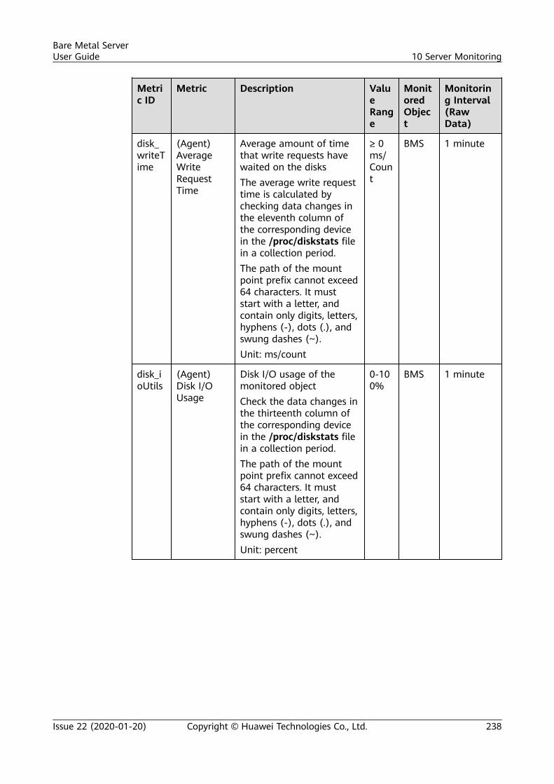
Metric ID
Metric Description ValueRange
MonitoredObject
Monitoring Interval(RawData)
disk_writeTime
(Agent)AverageWriteRequestTime
Average amount of timethat write requests havewaited on the disksThe average write requesttime is calculated bychecking data changes inthe eleventh column ofthe corresponding devicein the /proc/diskstats filein a collection period.The path of the mountpoint prefix cannot exceed64 characters. It muststart with a letter, andcontain only digits, letters,hyphens (-), dots (.), andswung dashes (~).Unit: ms/count
≥ 0ms/Count
BMS 1 minute
disk_ioUtils
(Agent)Disk I/OUsage
Disk I/O usage of themonitored objectCheck the data changes inthe thirteenth column ofthe corresponding devicein the /proc/diskstats filein a collection period.The path of the mountpoint prefix cannot exceed64 characters. It muststart with a letter, andcontain only digits, letters,hyphens (-), dots (.), andswung dashes (~).Unit: percent
0-100%
BMS 1 minute
Bare Metal ServerUser Guide 10 Server Monitoring
Issue 22 (2020-01-20) Copyright © Huawei Technologies Co., Ltd. 238
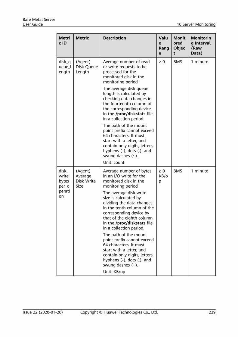
Metric ID
Metric Description ValueRange
MonitoredObject
Monitoring Interval(RawData)
disk_queue_length
(Agent)Disk QueueLength
Average number of reador write requests to beprocessed for themonitored disk in themonitoring periodThe average disk queuelength is calculated bychecking data changes inthe fourteenth column ofthe corresponding devicein the /proc/diskstats filein a collection period.The path of the mountpoint prefix cannot exceed64 characters. It muststart with a letter, andcontain only digits, letters,hyphens (-), dots (.), andswung dashes (~).Unit: count
≥ 0 BMS 1 minute
disk_write_bytes_per_operation
(Agent)AverageDisk WriteSize
Average number of bytesin an I/O write for themonitored disk in themonitoring periodThe average disk writesize is calculated bydividing the data changesin the tenth column of thecorresponding device bythat of the eighth columnin the /proc/diskstats filein a collection period.The path of the mountpoint prefix cannot exceed64 characters. It muststart with a letter, andcontain only digits, letters,hyphens (-), dots (.), andswung dashes (~).Unit: KB/op
≥ 0KB/op
BMS 1 minute
Bare Metal ServerUser Guide 10 Server Monitoring
Issue 22 (2020-01-20) Copyright © Huawei Technologies Co., Ltd. 239
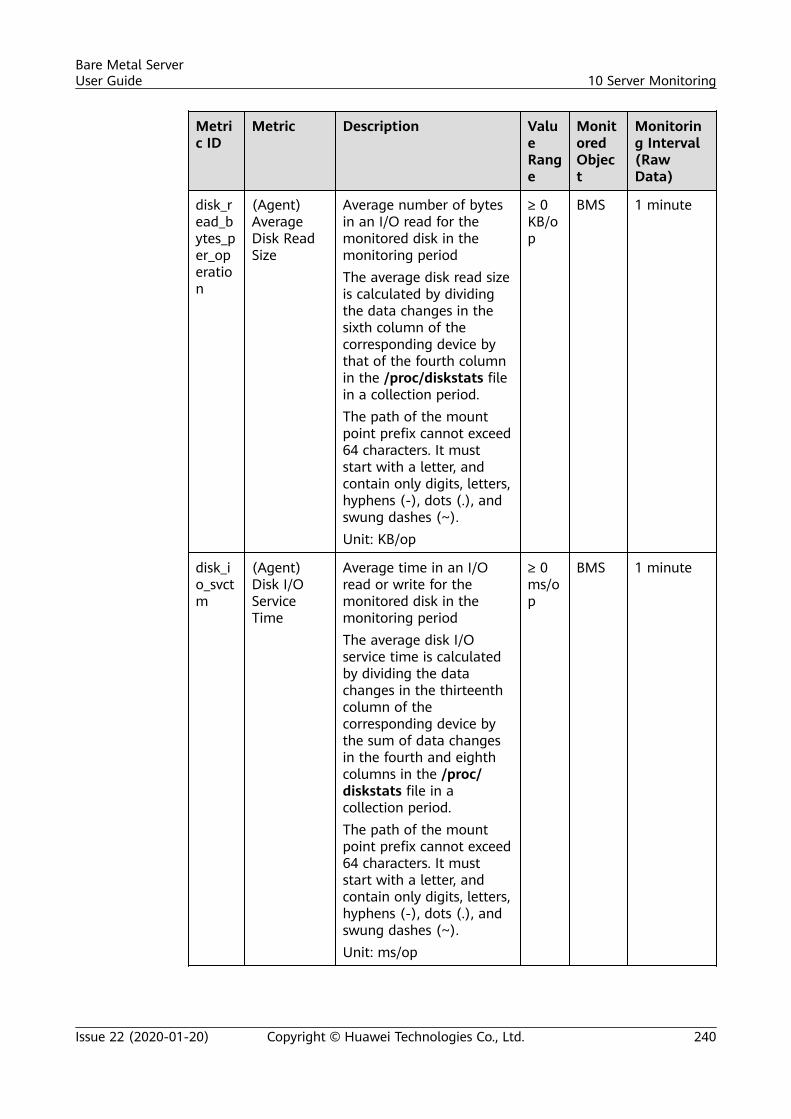
Metric ID
Metric Description ValueRange
MonitoredObject
Monitoring Interval(RawData)
disk_read_bytes_per_operation
(Agent)AverageDisk ReadSize
Average number of bytesin an I/O read for themonitored disk in themonitoring periodThe average disk read sizeis calculated by dividingthe data changes in thesixth column of thecorresponding device bythat of the fourth columnin the /proc/diskstats filein a collection period.The path of the mountpoint prefix cannot exceed64 characters. It muststart with a letter, andcontain only digits, letters,hyphens (-), dots (.), andswung dashes (~).Unit: KB/op
≥ 0KB/op
BMS 1 minute
disk_io_svctm
(Agent)Disk I/OServiceTime
Average time in an I/Oread or write for themonitored disk in themonitoring periodThe average disk I/Oservice time is calculatedby dividing the datachanges in the thirteenthcolumn of thecorresponding device bythe sum of data changesin the fourth and eighthcolumns in the /proc/diskstats file in acollection period.The path of the mountpoint prefix cannot exceed64 characters. It muststart with a letter, andcontain only digits, letters,hyphens (-), dots (.), andswung dashes (~).Unit: ms/op
≥ 0ms/op
BMS 1 minute
Bare Metal ServerUser Guide 10 Server Monitoring
Issue 22 (2020-01-20) Copyright © Huawei Technologies Co., Ltd. 240
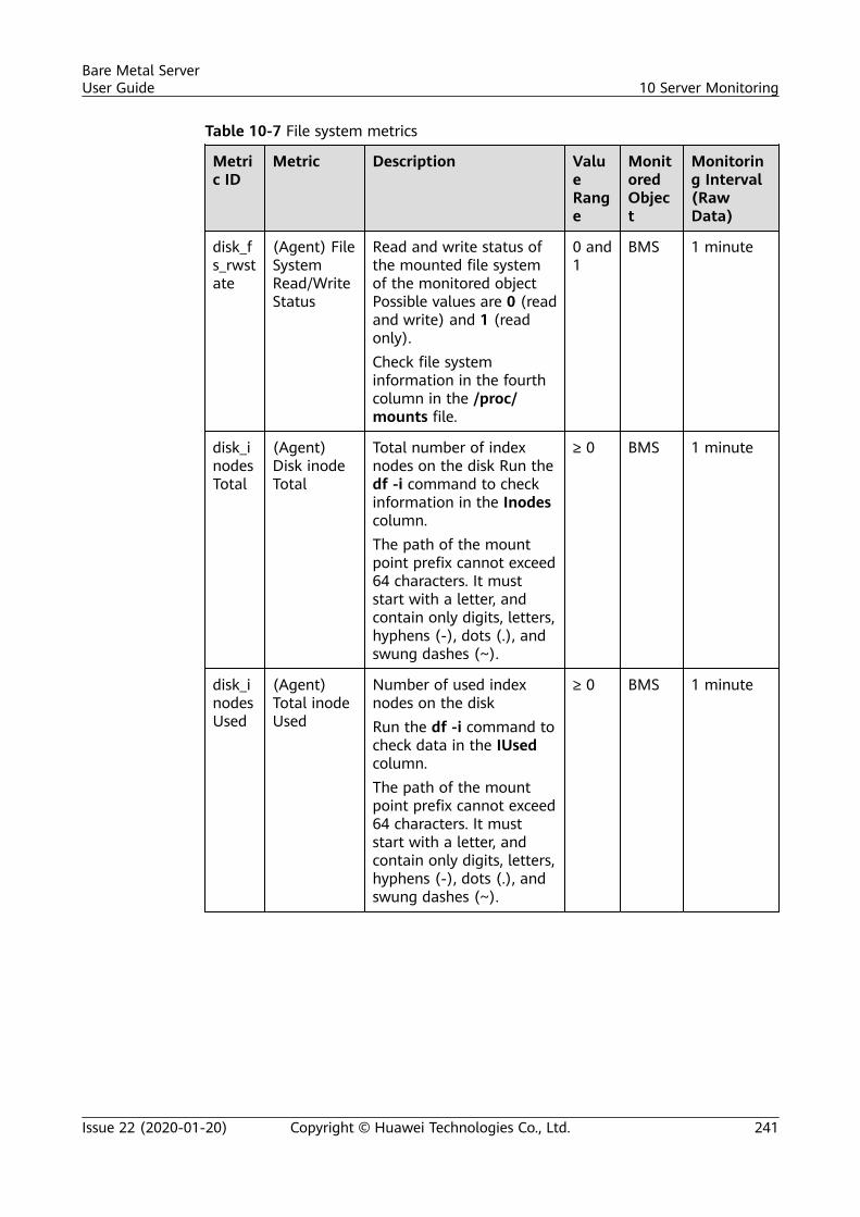
Table 10-7 File system metrics
Metric ID
Metric Description ValueRange
MonitoredObject
Monitoring Interval(RawData)
disk_fs_rwstate
(Agent) FileSystemRead/WriteStatus
Read and write status ofthe mounted file systemof the monitored objectPossible values are 0 (readand write) and 1 (readonly).Check file systeminformation in the fourthcolumn in the /proc/mounts file.
0 and1
BMS 1 minute
disk_inodesTotal
(Agent)Disk inodeTotal
Total number of indexnodes on the disk Run thedf -i command to checkinformation in the Inodescolumn.The path of the mountpoint prefix cannot exceed64 characters. It muststart with a letter, andcontain only digits, letters,hyphens (-), dots (.), andswung dashes (~).
≥ 0 BMS 1 minute
disk_inodesUsed
(Agent)Total inodeUsed
Number of used indexnodes on the diskRun the df -i command tocheck data in the IUsedcolumn.The path of the mountpoint prefix cannot exceed64 characters. It muststart with a letter, andcontain only digits, letters,hyphens (-), dots (.), andswung dashes (~).
≥ 0 BMS 1 minute
Bare Metal ServerUser Guide 10 Server Monitoring
Issue 22 (2020-01-20) Copyright © Huawei Technologies Co., Ltd. 241
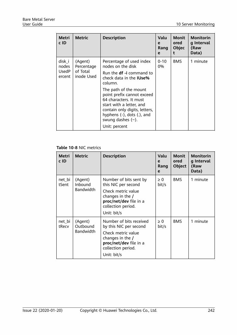
Metric ID
Metric Description ValueRange
MonitoredObject
Monitoring Interval(RawData)
disk_inodesUsedPercent
(Agent)Percentageof Totalinode Used
Percentage of used indexnodes on the diskRun the df -i command tocheck data in the IUse%column.The path of the mountpoint prefix cannot exceed64 characters. It muststart with a letter, andcontain only digits, letters,hyphens (-), dots (.), andswung dashes (~).Unit: percent
0-100%
BMS 1 minute
Table 10-8 NIC metrics
Metric ID
Metric Description ValueRange
MonitoredObject
Monitoring Interval(RawData)
net_bitSent
(Agent)InboundBandwidth
Number of bits sent bythis NIC per secondCheck metric valuechanges in the /proc/net/dev file in acollection period.Unit: bit/s
≥ 0bit/s
BMS 1 minute
net_bitRecv
(Agent)OutboundBandwidth
Number of bits receivedby this NIC per secondCheck metric valuechanges in the /proc/net/dev file in acollection period.Unit: bit/s
≥ 0bit/s
BMS 1 minute
Bare Metal ServerUser Guide 10 Server Monitoring
Issue 22 (2020-01-20) Copyright © Huawei Technologies Co., Ltd. 242
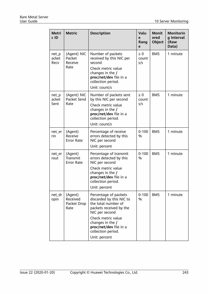
Metric ID
Metric Description ValueRange
MonitoredObject
Monitoring Interval(RawData)
net_packetRecv
(Agent) NICPacketReceiveRate
Number of packetsreceived by this NIC persecondCheck metric valuechanges in the /proc/net/dev file in acollection period.Unit: count/s
≥ 0counts/s
BMS 1 minute
net_packetSent
(Agent) NICPacket SendRate
Number of packets sentby this NIC per secondCheck metric valuechanges in the /proc/net/dev file in acollection period.Unit: count/s
≥ 0counts/s
BMS 1 minute
net_errin
(Agent)ReceiveError Rate
Percentage of receiveerrors detected by thisNIC per secondUnit: percent
0-100%
BMS 1 minute
net_errout
(Agent)TransmitError Rate
Percentage of transmiterrors detected by thisNIC per secondCheck metric valuechanges in the /proc/net/dev file in acollection period.Unit: percent
0-100%
BMS 1 minute
net_dropin
(Agent)ReceivedPacket DropRate
Percentage of packetsdiscarded by this NIC tothe total number ofpackets received by theNIC per secondCheck metric valuechanges in the /proc/net/dev file in acollection period.Unit: percent
0-100%
BMS 1 minute
Bare Metal ServerUser Guide 10 Server Monitoring
Issue 22 (2020-01-20) Copyright © Huawei Technologies Co., Ltd. 243
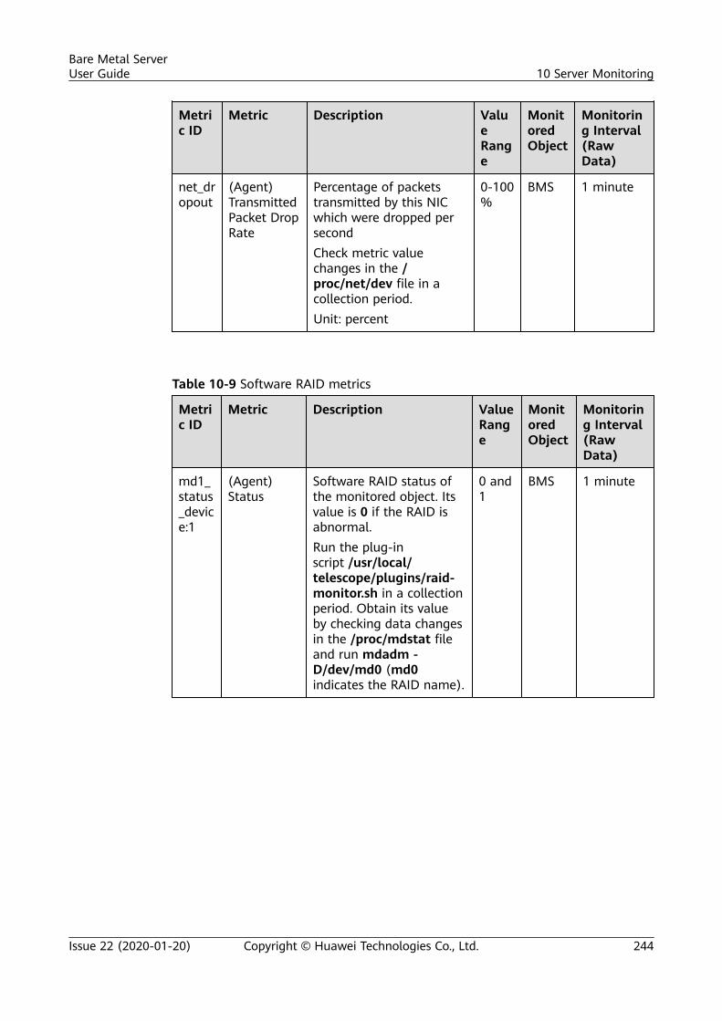
Metric ID
Metric Description ValueRange
MonitoredObject
Monitoring Interval(RawData)
net_dropout
(Agent)TransmittedPacket DropRate
Percentage of packetstransmitted by this NICwhich were dropped persecondCheck metric valuechanges in the /proc/net/dev file in acollection period.Unit: percent
0-100%
BMS 1 minute
Table 10-9 Software RAID metrics
Metric ID
Metric Description ValueRange
MonitoredObject
Monitoring Interval(RawData)
md1_status_device:1
(Agent)Status
Software RAID status ofthe monitored object. Itsvalue is 0 if the RAID isabnormal.Run the plug-inscript /usr/local/telescope/plugins/raid-monitor.sh in a collectionperiod. Obtain its valueby checking data changesin the /proc/mdstat fileand run mdadm -D/dev/md0 (md0indicates the RAID name).
0 and1
BMS 1 minute
Bare Metal ServerUser Guide 10 Server Monitoring
Issue 22 (2020-01-20) Copyright © Huawei Technologies Co., Ltd. 244
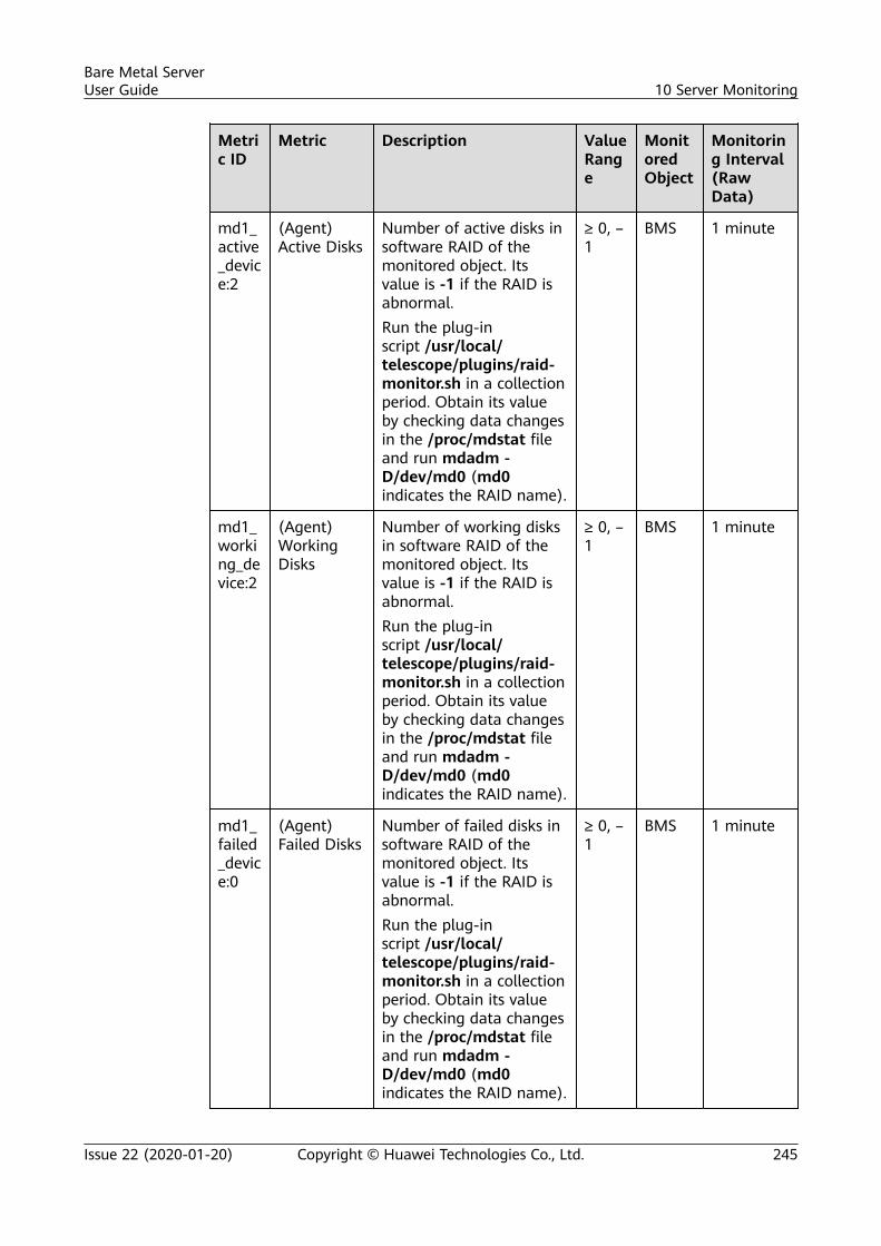
Metric ID
Metric Description ValueRange
MonitoredObject
Monitoring Interval(RawData)
md1_active_device:2
(Agent)Active Disks
Number of active disks insoftware RAID of themonitored object. Itsvalue is -1 if the RAID isabnormal.Run the plug-inscript /usr/local/telescope/plugins/raid-monitor.sh in a collectionperiod. Obtain its valueby checking data changesin the /proc/mdstat fileand run mdadm -D/dev/md0 (md0indicates the RAID name).
≥ 0, –1
BMS 1 minute
md1_working_device:2
(Agent)WorkingDisks
Number of working disksin software RAID of themonitored object. Itsvalue is -1 if the RAID isabnormal.Run the plug-inscript /usr/local/telescope/plugins/raid-monitor.sh in a collectionperiod. Obtain its valueby checking data changesin the /proc/mdstat fileand run mdadm -D/dev/md0 (md0indicates the RAID name).
≥ 0, –1
BMS 1 minute
md1_failed_device:0
(Agent)Failed Disks
Number of failed disks insoftware RAID of themonitored object. Itsvalue is -1 if the RAID isabnormal.Run the plug-inscript /usr/local/telescope/plugins/raid-monitor.sh in a collectionperiod. Obtain its valueby checking data changesin the /proc/mdstat fileand run mdadm -D/dev/md0 (md0indicates the RAID name).
≥ 0, –1
BMS 1 minute
Bare Metal ServerUser Guide 10 Server Monitoring
Issue 22 (2020-01-20) Copyright © Huawei Technologies Co., Ltd. 245
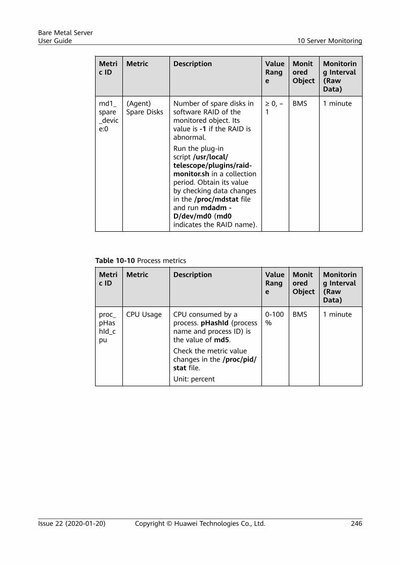
Metric ID
Metric Description ValueRange
MonitoredObject
Monitoring Interval(RawData)
md1_spare_device:0
(Agent)Spare Disks
Number of spare disks insoftware RAID of themonitored object. Itsvalue is -1 if the RAID isabnormal.Run the plug-inscript /usr/local/telescope/plugins/raid-monitor.sh in a collectionperiod. Obtain its valueby checking data changesin the /proc/mdstat fileand run mdadm -D/dev/md0 (md0indicates the RAID name).
≥ 0, –1
BMS 1 minute
Table 10-10 Process metrics
Metric ID
Metric Description ValueRange
MonitoredObject
Monitoring Interval(RawData)
proc_pHashId_cpu
CPU Usage CPU consumed by aprocess. pHashId (processname and process ID) isthe value of md5.Check the metric valuechanges in the /proc/pid/stat file.Unit: percent
0-100%
BMS 1 minute
Bare Metal ServerUser Guide 10 Server Monitoring
Issue 22 (2020-01-20) Copyright © Huawei Technologies Co., Ltd. 246
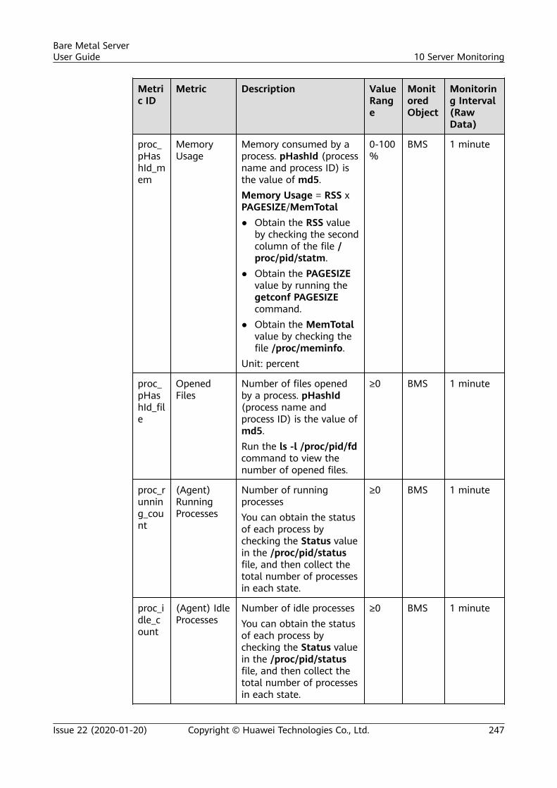
Metric ID
Metric Description ValueRange
MonitoredObject
Monitoring Interval(RawData)
proc_pHashId_mem
MemoryUsage
Memory consumed by aprocess. pHashId (processname and process ID) isthe value of md5.Memory Usage = RSS xPAGESIZE/MemTotal● Obtain the RSS value
by checking the secondcolumn of the file /proc/pid/statm.
● Obtain the PAGESIZEvalue by running thegetconf PAGESIZEcommand.
● Obtain the MemTotalvalue by checking thefile /proc/meminfo.
Unit: percent
0-100%
BMS 1 minute
proc_pHashId_file
OpenedFiles
Number of files openedby a process. pHashId(process name andprocess ID) is the value ofmd5.Run the ls -l /proc/pid/fdcommand to view thenumber of opened files.
≥0 BMS 1 minute
proc_running_count
(Agent)RunningProcesses
Number of runningprocessesYou can obtain the statusof each process bychecking the Status valuein the /proc/pid/statusfile, and then collect thetotal number of processesin each state.
≥0 BMS 1 minute
proc_idle_count
(Agent) IdleProcesses
Number of idle processesYou can obtain the statusof each process bychecking the Status valuein the /proc/pid/statusfile, and then collect thetotal number of processesin each state.
≥0 BMS 1 minute
Bare Metal ServerUser Guide 10 Server Monitoring
Issue 22 (2020-01-20) Copyright © Huawei Technologies Co., Ltd. 247
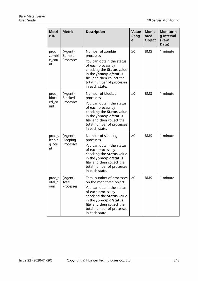
Metric ID
Metric Description ValueRange
MonitoredObject
Monitoring Interval(RawData)
proc_zombie_count
(Agent)ZombieProcesses
Number of zombieprocessesYou can obtain the statusof each process bychecking the Status valuein the /proc/pid/statusfile, and then collect thetotal number of processesin each state.
≥0 BMS 1 minute
proc_blocked_count
(Agent)BlockedProcesses
Number of blockedprocessesYou can obtain the statusof each process bychecking the Status valuein the /proc/pid/statusfile, and then collect thetotal number of processesin each state.
≥0 BMS 1 minute
proc_sleeping_count
(Agent)SleepingProcesses
Number of sleepingprocessesYou can obtain the statusof each process bychecking the Status valuein the /proc/pid/statusfile, and then collect thetotal number of processesin each state.
≥0 BMS 1 minute
proc_total_coun
(Agent)TotalProcesses
Total number of processeson the monitored objectYou can obtain the statusof each process bychecking the Status valuein the /proc/pid/statusfile, and then collect thetotal number of processesin each state.
≥0 BMS 1 minute
Bare Metal ServerUser Guide 10 Server Monitoring
Issue 22 (2020-01-20) Copyright © Huawei Technologies Co., Ltd. 248
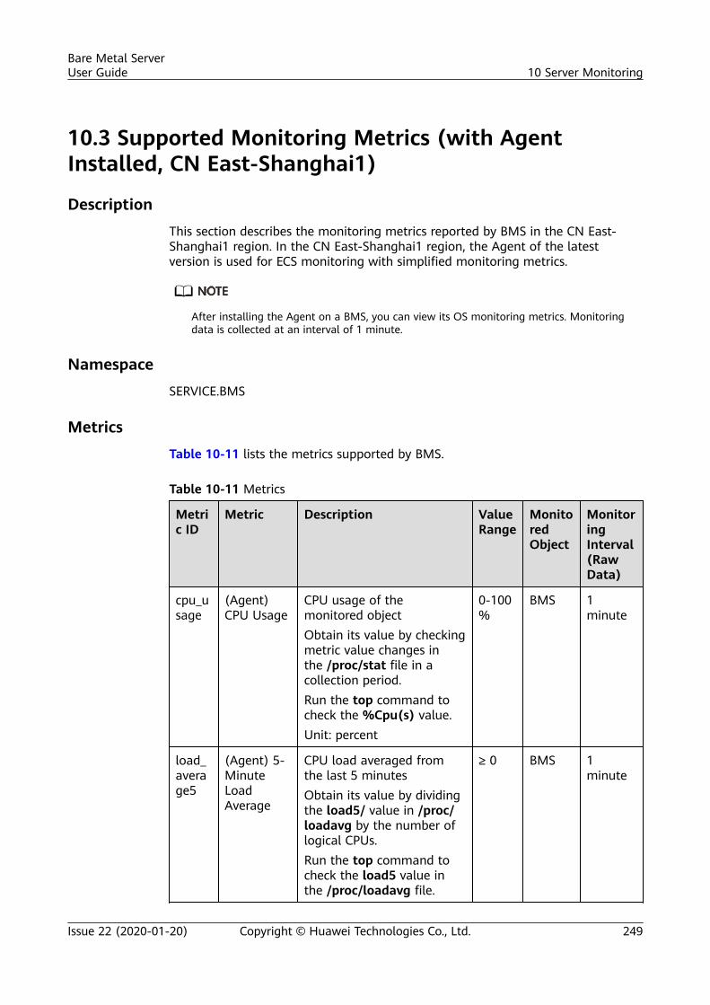
10.3 Supported Monitoring Metrics (with AgentInstalled, CN East-Shanghai1)
Description
This section describes the monitoring metrics reported by BMS in the CN East-Shanghai1 region. In the CN East-Shanghai1 region, the Agent of the latestversion is used for ECS monitoring with simplified monitoring metrics.
After installing the Agent on a BMS, you can view its OS monitoring metrics. Monitoringdata is collected at an interval of 1 minute.
Namespace
SERVICE.BMS
Metrics
Table 10-11 lists the metrics supported by BMS.
Table 10-11 Metrics
Metric ID
Metric Description ValueRange
MonitoredObject
MonitoringInterval(RawData)
cpu_usage
(Agent)CPU Usage
CPU usage of themonitored objectObtain its value by checkingmetric value changes inthe /proc/stat file in acollection period.Run the top command tocheck the %Cpu(s) value.Unit: percent
0-100%
BMS 1minute
load_average5
(Agent) 5-MinuteLoadAverage
CPU load averaged fromthe last 5 minutesObtain its value by dividingthe load5/ value in /proc/loadavg by the number oflogical CPUs.Run the top command tocheck the load5 value inthe /proc/loadavg file.
≥ 0 BMS 1minute
Bare Metal ServerUser Guide 10 Server Monitoring
Issue 22 (2020-01-20) Copyright © Huawei Technologies Co., Ltd. 249
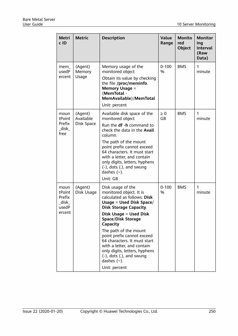
Metric ID
Metric Description ValueRange
MonitoredObject
MonitoringInterval(RawData)
mem_usedPercent
(Agent)MemoryUsage
Memory usage of themonitored objectObtain its value by checkingthe file /proc/meminfo.Memory Usage =(MemTotal -MemAvailable)/MemTotalUnit: percent
0-100%
BMS 1minute
mountPointPrefix_disk_free
(Agent)AvailableDisk Space
Available disk space of themonitored objectRun the df -h command tocheck the data in the Availcolumn.The path of the mountpoint prefix cannot exceed64 characters. It must startwith a letter, and containonly digits, letters, hyphens(-), dots (.), and swungdashes (~).Unit: GB
≥ 0GB
BMS 1minute
mountPointPrefix_disk_usedPercent
(Agent)Disk Usage
Disk usage of themonitored object. It iscalculated as follows: DiskUsage = Used Disk Space/Disk Storage Capacity.Disk Usage = Used DiskSpace/Disk StorageCapacityThe path of the mountpoint prefix cannot exceed64 characters. It must startwith a letter, and containonly digits, letters, hyphens(-), dots (.), and swungdashes (~).Unit: percent
0-100%
BMS 1minute
Bare Metal ServerUser Guide 10 Server Monitoring
Issue 22 (2020-01-20) Copyright © Huawei Technologies Co., Ltd. 250
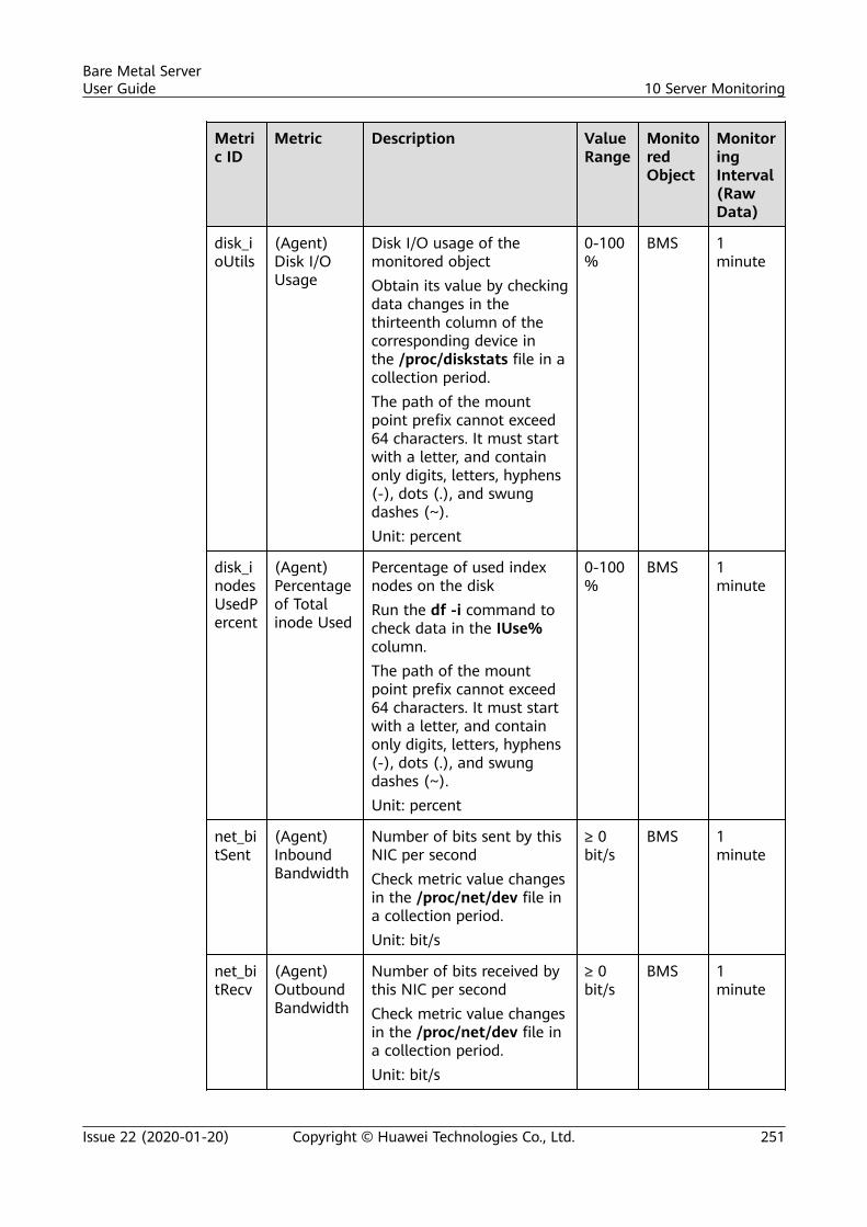
Metric ID
Metric Description ValueRange
MonitoredObject
MonitoringInterval(RawData)
disk_ioUtils
(Agent)Disk I/OUsage
Disk I/O usage of themonitored objectObtain its value by checkingdata changes in thethirteenth column of thecorresponding device inthe /proc/diskstats file in acollection period.The path of the mountpoint prefix cannot exceed64 characters. It must startwith a letter, and containonly digits, letters, hyphens(-), dots (.), and swungdashes (~).Unit: percent
0-100%
BMS 1minute
disk_inodesUsedPercent
(Agent)Percentageof Totalinode Used
Percentage of used indexnodes on the diskRun the df -i command tocheck data in the IUse%column.The path of the mountpoint prefix cannot exceed64 characters. It must startwith a letter, and containonly digits, letters, hyphens(-), dots (.), and swungdashes (~).Unit: percent
0-100%
BMS 1minute
net_bitSent
(Agent)InboundBandwidth
Number of bits sent by thisNIC per secondCheck metric value changesin the /proc/net/dev file ina collection period.Unit: bit/s
≥ 0bit/s
BMS 1minute
net_bitRecv
(Agent)OutboundBandwidth
Number of bits received bythis NIC per secondCheck metric value changesin the /proc/net/dev file ina collection period.Unit: bit/s
≥ 0bit/s
BMS 1minute
Bare Metal ServerUser Guide 10 Server Monitoring
Issue 22 (2020-01-20) Copyright © Huawei Technologies Co., Ltd. 251
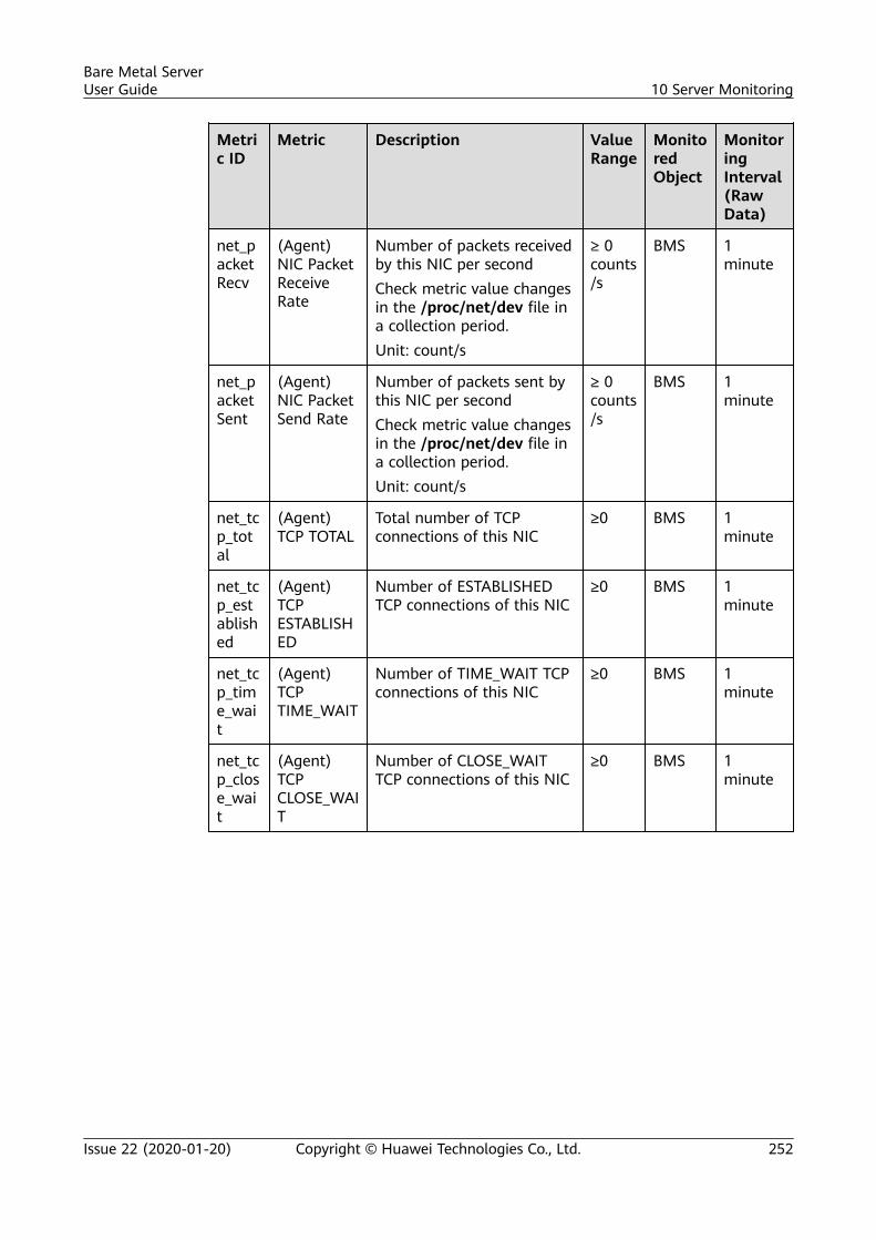
Metric ID
Metric Description ValueRange
MonitoredObject
MonitoringInterval(RawData)
net_packetRecv
(Agent)NIC PacketReceiveRate
Number of packets receivedby this NIC per secondCheck metric value changesin the /proc/net/dev file ina collection period.Unit: count/s
≥ 0counts/s
BMS 1minute
net_packetSent
(Agent)NIC PacketSend Rate
Number of packets sent bythis NIC per secondCheck metric value changesin the /proc/net/dev file ina collection period.Unit: count/s
≥ 0counts/s
BMS 1minute
net_tcp_total
(Agent)TCP TOTAL
Total number of TCPconnections of this NIC
≥0 BMS 1minute
net_tcp_established
(Agent)TCPESTABLISHED
Number of ESTABLISHEDTCP connections of this NIC
≥0 BMS 1minute
net_tcp_time_wait
(Agent)TCPTIME_WAIT
Number of TIME_WAIT TCPconnections of this NIC
≥0 BMS 1minute
net_tcp_close_wait
(Agent)TCPCLOSE_WAIT
Number of CLOSE_WAITTCP connections of this NIC
≥0 BMS 1minute
Bare Metal ServerUser Guide 10 Server Monitoring
Issue 22 (2020-01-20) Copyright © Huawei Technologies Co., Ltd. 252
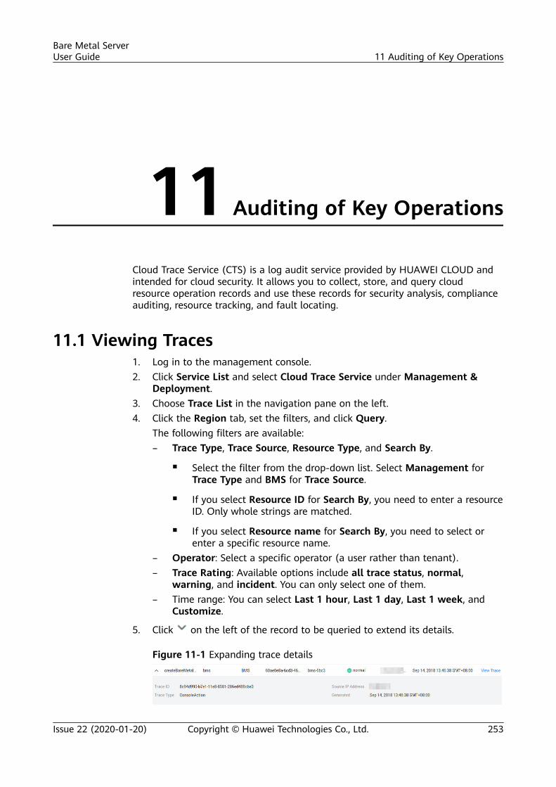
11 Auditing of Key Operations
Cloud Trace Service (CTS) is a log audit service provided by HUAWEI CLOUD andintended for cloud security. It allows you to collect, store, and query cloudresource operation records and use these records for security analysis, complianceauditing, resource tracking, and fault locating.
11.1 Viewing Traces1. Log in to the management console.2. Click Service List and select Cloud Trace Service under Management &
Deployment.3. Choose Trace List in the navigation pane on the left.4. Click the Region tab, set the filters, and click Query.
The following filters are available:– Trace Type, Trace Source, Resource Type, and Search By.
▪ Select the filter from the drop-down list. Select Management forTrace Type and BMS for Trace Source.
▪ If you select Resource ID for Search By, you need to enter a resourceID. Only whole strings are matched.
▪ If you select Resource name for Search By, you need to select orenter a specific resource name.
– Operator: Select a specific operator (a user rather than tenant).– Trace Rating: Available options include all trace status, normal,
warning, and incident. You can only select one of them.– Time range: You can select Last 1 hour, Last 1 day, Last 1 week, and
Customize.
5. Click on the left of the record to be queried to extend its details.
Figure 11-1 Expanding trace details
Bare Metal ServerUser Guide 11 Auditing of Key Operations
Issue 22 (2020-01-20) Copyright © Huawei Technologies Co., Ltd. 253
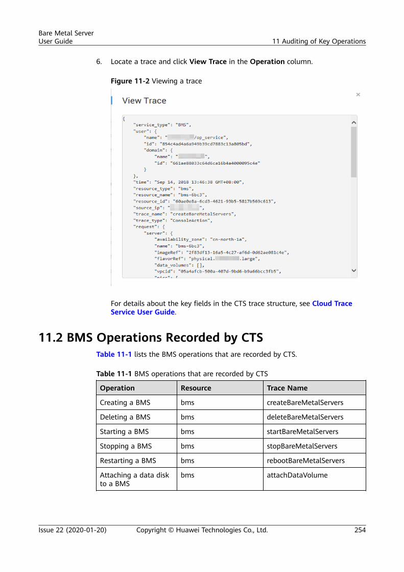
6. Locate a trace and click View Trace in the Operation column.
Figure 11-2 Viewing a trace
For details about the key fields in the CTS trace structure, see Cloud TraceService User Guide.
11.2 BMS Operations Recorded by CTSTable 11-1 lists the BMS operations that are recorded by CTS.
Table 11-1 BMS operations that are recorded by CTS
Operation Resource Trace Name
Creating a BMS bms createBareMetalServers
Deleting a BMS bms deleteBareMetalServers
Starting a BMS bms startBareMetalServers
Stopping a BMS bms stopBareMetalServers
Restarting a BMS bms rebootBareMetalServers
Attaching a data diskto a BMS
bms attachDataVolume
Bare Metal ServerUser Guide 11 Auditing of Key Operations
Issue 22 (2020-01-20) Copyright © Huawei Technologies Co., Ltd. 254

Operation Resource Trace Name
Detaching a data diskfrom a BMS
bms detachDataVolume
Bare Metal ServerUser Guide 11 Auditing of Key Operations
Issue 22 (2020-01-20) Copyright © Huawei Technologies Co., Ltd. 255
12 Troubleshooting
12.1 What Can I Do If I Cannot Log In to My BMS orthe BMS EVS Disk Is Lost After the BMS Is Started orRestarted?
Issue Description
After a BMS is started or restarted, the user cannot log in to the BMS or the BMSEVS disk is lost.
Possible Causes
The BMS cannot obtain the IP address or the EVS disk cannot be attached to theBMS because packet loss caused by network congestion occurs.
Solution
Restart the BMS. If the fault still exists after you restart the BMS for several times,contact the customer service.
12.2 What Should I Do If a Key Pair Created UsingPuTTYgen Cannot Be Imported to the ManagementConsole?
Symptom
When a key pair created using PuTTYgen was imported to the managementconsole, the system displayed a message indicating that importing the public keyfailed.
Bare Metal ServerUser Guide 12 Troubleshooting
Issue 22 (2020-01-20) Copyright © Huawei Technologies Co., Ltd. 256
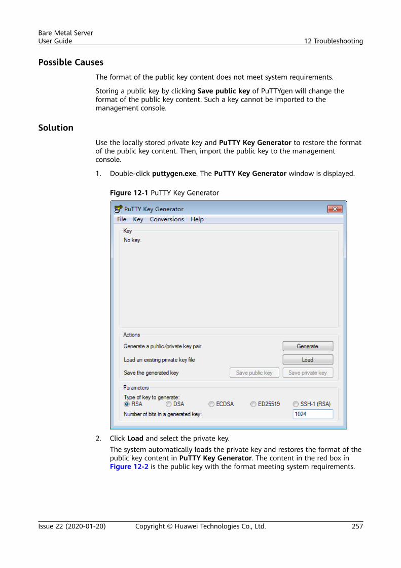
Possible CausesThe format of the public key content does not meet system requirements.
Storing a public key by clicking Save public key of PuTTYgen will change theformat of the public key content. Such a key cannot be imported to themanagement console.
SolutionUse the locally stored private key and PuTTY Key Generator to restore the formatof the public key content. Then, import the public key to the managementconsole.
1. Double-click puttygen.exe. The PuTTY Key Generator window is displayed.
Figure 12-1 PuTTY Key Generator
2. Click Load and select the private key.The system automatically loads the private key and restores the format of thepublic key content in PuTTY Key Generator. The content in the red box inFigure 12-2 is the public key with the format meeting system requirements.
Bare Metal ServerUser Guide 12 Troubleshooting
Issue 22 (2020-01-20) Copyright © Huawei Technologies Co., Ltd. 257
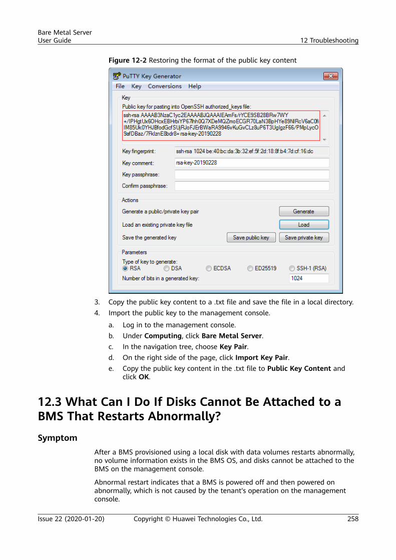
Figure 12-2 Restoring the format of the public key content
3. Copy the public key content to a .txt file and save the file in a local directory.4. Import the public key to the management console.
a. Log in to the management console.b. Under Computing, click Bare Metal Server.c. In the navigation tree, choose Key Pair.d. On the right side of the page, click Import Key Pair.e. Copy the public key content in the .txt file to Public Key Content and
click OK.
12.3 What Can I Do If Disks Cannot Be Attached to aBMS That Restarts Abnormally?
SymptomAfter a BMS provisioned using a local disk with data volumes restarts abnormally,no volume information exists in the BMS OS, and disks cannot be attached to theBMS on the management console.
Abnormal restart indicates that a BMS is powered off and then powered onabnormally, which is not caused by the tenant's operation on the managementconsole.
Bare Metal ServerUser Guide 12 Troubleshooting
Issue 22 (2020-01-20) Copyright © Huawei Technologies Co., Ltd. 258
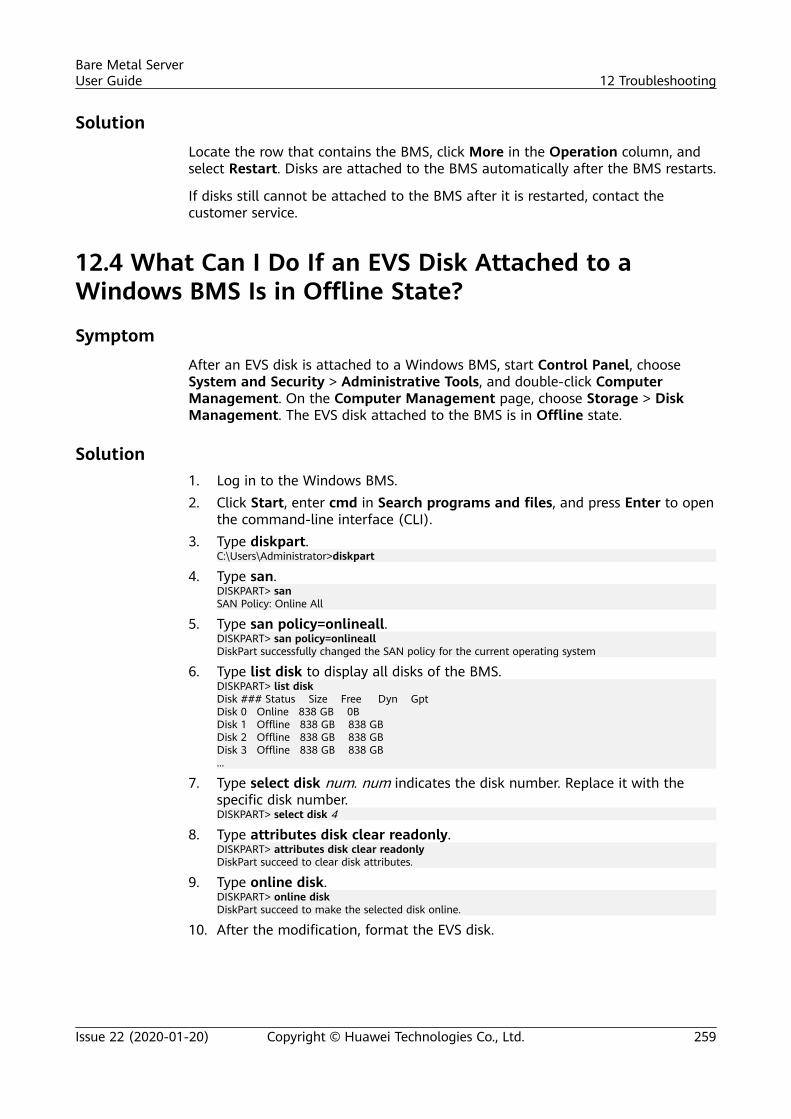
SolutionLocate the row that contains the BMS, click More in the Operation column, andselect Restart. Disks are attached to the BMS automatically after the BMS restarts.
If disks still cannot be attached to the BMS after it is restarted, contact thecustomer service.
12.4 What Can I Do If an EVS Disk Attached to aWindows BMS Is in Offline State?
SymptomAfter an EVS disk is attached to a Windows BMS, start Control Panel, chooseSystem and Security > Administrative Tools, and double-click ComputerManagement. On the Computer Management page, choose Storage > DiskManagement. The EVS disk attached to the BMS is in Offline state.
Solution1. Log in to the Windows BMS.2. Click Start, enter cmd in Search programs and files, and press Enter to open
the command-line interface (CLI).3. Type diskpart.
C:\Users\Administrator>diskpart
4. Type san.DISKPART> sanSAN Policy: Online All
5. Type san policy=onlineall.DISKPART> san policy=onlineallDiskPart successfully changed the SAN policy for the current operating system
6. Type list disk to display all disks of the BMS.DISKPART> list diskDisk ### Status Size Free Dyn GptDisk 0 Online 838 GB 0BDisk 1 Offline 838 GB 838 GBDisk 2 Offline 838 GB 838 GBDisk 3 Offline 838 GB 838 GB...
7. Type select disk num. num indicates the disk number. Replace it with thespecific disk number.DISKPART> select disk 4
8. Type attributes disk clear readonly.DISKPART> attributes disk clear readonlyDiskPart succeed to clear disk attributes.
9. Type online disk.DISKPART> online diskDiskPart succeed to make the selected disk online.
10. After the modification, format the EVS disk.
Bare Metal ServerUser Guide 12 Troubleshooting
Issue 22 (2020-01-20) Copyright © Huawei Technologies Co., Ltd. 259
A Change History
Released On Description
2020-01-20 This issue is the twenty-second official release.● Modified the permission description and operations
in Permissions Management because of theoptimization of the IAM management console.
● Moved the Agent installation guide from ServerMonitoring to the Cloud Eye documentation.
2019-12-30 This issue is the twenty-first official release.Added the following content:Supported Monitoring Metrics (with Agent Installed,CN East-Shanghai1)Modified the following content:Modified the method of configuring permissions for auser group in Creating a User and GrantingPermissions.
2019-11-30 This issue is the twentieth official release.Added the following content:Examples of Custom Policies for Networks and ACLsModified the following content:● Modified the method of associating multiple security
groups with a BMS in Changing a Security Group.● Added the creation of a custom policy in the Visual
editor in Creating a Custom Policy.
2019-10-30 This issue is the nineteenth official release.Added process metrics in Supported MonitoringMetrics (with Agent Installed).
2019-09-25 This issue is the eighteenth official release.Added Changing the Private IP Address.
Bare Metal ServerUser Guide A Change History
Issue 22 (2020-01-20) Copyright © Huawei Technologies Co., Ltd. 260
Released On Description
2019-07-30 This issue is the seventeenth official release.Added the following content:● Creating a Dedicated BMS● Changing the Name of a BMS● Private Image Overview● OverviewModified the following content:● Adjusted the outline of Instance.● Added a table displaying the requirements and
differences between login methods in Linux BMSLogin Methods.
● Added suggestions for using security groups inAdding Security Group Rules.
2019-05-30 This issue is the sixteenth official release.● Added Permissions Management and User-defined
Network ACL.● Added Tag and enabled you to add tags to BMSs.
2019-04-25 This issue is the fifteenth official release.● Added the guide to changing the SID of a Windows
Server 2012 BMS in Creating a BMS.● Added verification operations in Resetting the BMS
Password.● Optimized descriptions in Metadata.
2019-03-18 This issue is the fourteenth official release.Optimized the whole document, including adjusting theoutline, optimizing feature descriptions, and addingscenario descriptions.
2018-09-14 This issue is the thirteenth official release.Added the following content:● Deleting the Password of a Windows BMS● Overview● BMS Operations Recorded by CTS● Viewing Traces
2018-08-22 This issue is the twelfth official release.● Added Exporting the BMS list.● Added the method of automatically updating the
BMS host name in How Do I Configure the StaticHost Name of a BMS?
Bare Metal ServerUser Guide A Change History
Issue 22 (2020-01-20) Copyright © Huawei Technologies Co., Ltd. 261
Released On Description
2018-03-30 This issue is the eleventh official release.● Added Backing Up a BMS.● Adjusted the structure.
2018-02-28 This issue is the tenth official release.Added the following content:● Metadata● Rebuilding a BMS● How Should I Set SSH Configuration Items?
2018-01-30 This issue is the ninth official release.Added the following content:● How Should I Select Storage?● How Can I Activate a Windows BMS?
2017-11-30 This issue is the eighth official release.Added the following content:● Injecting User Data into BMSs● Creating a Private Image from a BMS● Resetting the BMS Password● Reinstalling the OS
2017-10-30 This issue is the seventh official release.Modified the steps to add a security group rule inAdding Security Group Rules.
2017-09-30 This issue is the sixth official release.Added the following content:● Expanding Disk Capacity● Creating a Private Image from an External Image
FileModified the following content:Added an example of how to configure user-definedVLANs in Overview.
2017-08-30 This issue is the fifth official release.Optimized descriptions in Overview.
2017-07-31 This issue is the fourth official release.● Added Overview.● Optimized the procedure in Creating a BMS.
Bare Metal ServerUser Guide A Change History
Issue 22 (2020-01-20) Copyright © Huawei Technologies Co., Ltd. 262

Released On Description
2017-03-30 This issue is the third official release.Added the following content:● Binding an EIP to a BMS● Managing High-Speed Networks
2016-10-29 This issue is the second official release.Added Viewing BMS Creation Statuses.
2016-08-25 This issue is the first official release.
Bare Metal ServerUser Guide A Change History
Issue 22 (2020-01-20) Copyright © Huawei Technologies Co., Ltd. 263