Embed Size (px)
Citation preview

1
User guide for the balancing spread-sheet MiniBalance
Peter G. Schild
SINTEF Building & Infrastructure, Norway
Fig. 1 MiniBalance spreadsheet on smartphone
1 Functionality
“MiniBalance” is a simple but smart Microsoft Excel®
spreadsheet to assist balancing of air flows in mechanical
ventilation systems, i.e. adjusting dampers and air
terminal devices. It can be a timesaving tool for HVAC
contractors, using a smartphone, netbook or laptop on the
building site. MiniBalance applies the proportional
method of balancing, and other fluid dynamics theory.
Functions include:
Built-in ‘expertise’ tells you what to do at any time.
For example, it advises you which airflow or pressure
setting to set, which can be especially time-saving if
you are alone on the job. This function is self-learning,
giving progressively better suggestions.
Either "quick and approximate" or "slow and accurate"
balancing is possible. Quick balancing involves fewer
measurements and adjustments. See page 6.
You may choose any terminal/damper as the reference
for a balancing group, not necessarily the end
damper/terminal. Nor do you have to use the same
terminal as reference for the whole balancing group.
It can handle different units of measurement when you
use different measurement instruments at the air
terminals or dampers in ventilation system. Units
include cfm, ℓ/s, m³/h and pressure (by providing the
k-factor for e.g. air terminals).
MiniBalance works equally well with any fan curve,
i.e. anything between constant pressure and constant
volume.
The spreadsheet can be printed out to serve as
commissioning documentation.
No software installation is needed. Simply open the
small file in a spreadsheet application.
The spreadsheet contains no macros. Instead, the
calculations are done in formulae in cells in a hidden
worksheet. It can thus be used on smartphones and
imported into non-Microsoft spreadsheet applications.
Column headings have popup comments (in English)
that explain the meaning of the parameters in the
column. This helps to make the spreadsheet self-
explanatory.
The spreadsheet layout is kept simple so that many
columns can be viewed on small screens.
The spreadsheet is limited to 50 dampers/terminals.
This is so that it can be used on smartphones with slow
processors. For large duct systems, simply use
multiple copies of the spreadsheet file.
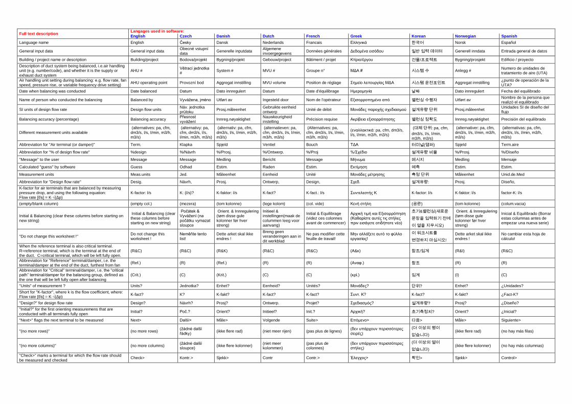
Presently, 9 languages are supported. See the table in
the appendix. The chosen interface language affects all
headings and output, but not the popup comments.
2 Versions
MiniBalance has been developed by SINTEF. There are
two versions:
MiniBalance.XLS: For Microsoft Office® Excel
versions 97 to 2003. This version can also be imported
into other non-Microsoft spreadsheet applications such
as OpenOffice (PC/linux/Mac), ‘Spreadsheet’ by Byte-
Squared (Android), Sheet² (iPhone/iPad),
‘Spreadsheet’ by AppAuthors Ltd. (iPhone/iPad), or
QuickOffice (Android/iPhone/iPad/Symbian).
2
MiniBalance.XLTX: Template file for Microsoft
Office® Excel 2007 and 2010. This version is also
suitable for smartphones running Microsoft Mobile or
Windows Phone operating system.
3 Scope of this user guide
This user guide explains how to use the MiniBalance
spreadsheet, with step-by-step examples.
The AIVC website also has a short training video about
MiniBalance.
It is highly recommended that you also read a good
guidebook on commissioning/TAB (testing, adjusting &
balancing) of duct systems, such as references [1] to [4].
The literature not only gives a good understanding of how
to successfully apply the Proportional Method of
balancing, but also other related issues such as proper
preparation and measurement methods. AIVC
Bibliography 11 [5] gives an overview of literature on the
topic.
4 Glossary
See the table at the end of this paper for keywords
translated into different languages.
Terminal: Air terminal device (e.g. supply diffuser or
exhaust terminal / grille). Such devices should have a
means of throttling (i.e. adjusting the flow resistance) that
can be fixed after it has been adjusted.
Damper: In-duct device for throttling (adjusting flow
resistance), such as butterfly device or adjustable iris
orifice.
Group: A row or collection of air terminals or dampers
that are balanced with each other, and for which their total
flow rate is collectively adjusted by a common balancing
damper (or fan) at the root of the duct. Examples of a
balancing group are: a main duct with a string of branches
each with a balancing damper, or a branch duct feeding a
string of air terminals. For example, the red boxes in
Fig. 2 are different balancing groups. At least one member
of each group (the ‘critical’ one) should be left fully open.
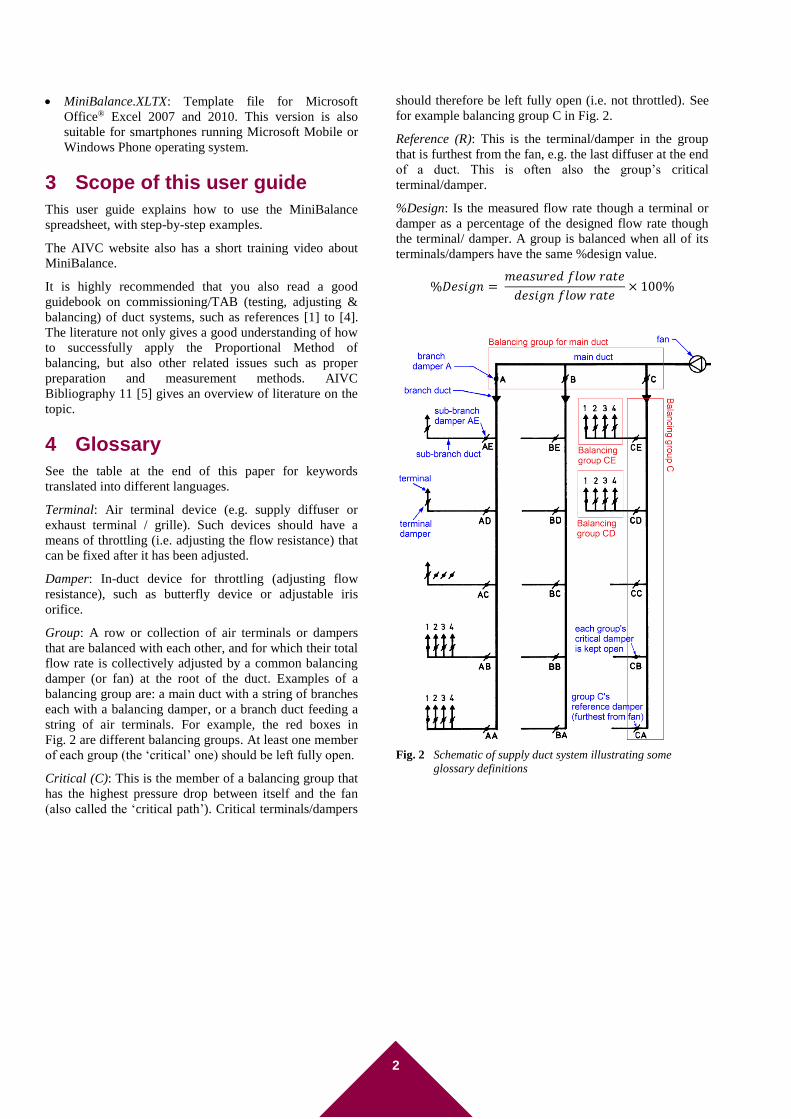
Critical (C): This is the member of a balancing group that
has the highest pressure drop between itself and the fan
(also called the ‘critical path’). Critical terminals/dampers
should therefore be left fully open (i.e. not throttled). See
for example balancing group C in Fig. 2.
Reference (R): This is the terminal/damper in the group
that is furthest from the fan, e.g. the last diffuser at the end
of a duct. This is often also the group’s critical
terminal/damper.
%Design: Is the measured flow rate though a terminal or
damper as a percentage of the designed flow rate though
the terminal/ damper. A group is balanced when all of its
terminals/dampers have the same %design value.
%𝐷𝑒𝑠𝑖𝑔𝑛 = 𝑚𝑒𝑎𝑠𝑢𝑟𝑒𝑑 𝑓𝑙𝑜𝑤 𝑟𝑎𝑡𝑒
𝑑𝑒𝑠𝑖𝑔𝑛 𝑓𝑙𝑜𝑤 𝑟𝑎𝑡𝑒× 100%
Fig. 2 Schematic of supply duct system illustrating some
glossary definitions
3
PART 1: Step-by-step examples using MiniBalance
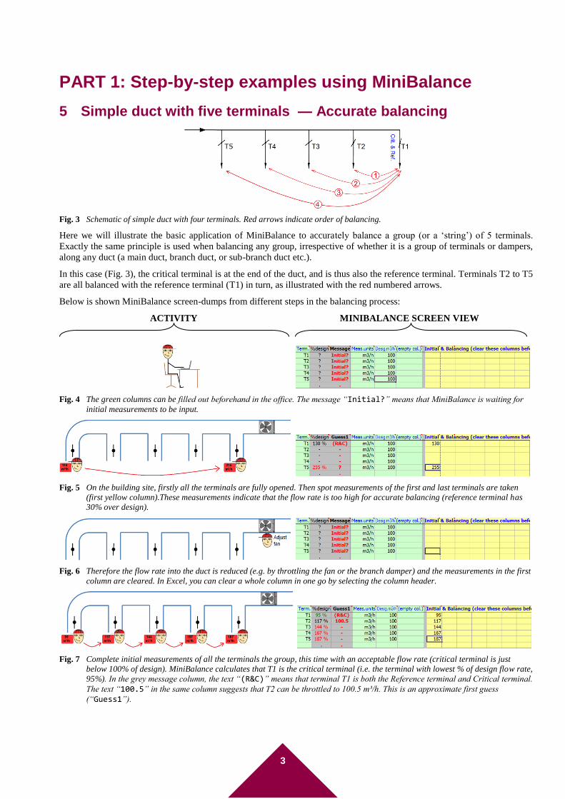
5 Simple duct with five terminals — Accurate balancing
Fig. 3 Schematic of simple duct with four terminals. Red arrows indicate order of balancing.
Here we will illustrate the basic application of MiniBalance to accurately balance a group (or a ‘string’) of 5 terminals.
Exactly the same principle is used when balancing any group, irrespective of whether it is a group of terminals or dampers,
along any duct (a main duct, branch duct, or sub-branch duct etc.).
In this case (Fig. 3), the critical terminal is at the end of the duct, and is thus also the reference terminal. Terminals T2 to T5
are all balanced with the reference terminal (T1) in turn, as illustrated with the red numbered arrows.
Below is shown MiniBalance screen-dumps from different steps in the balancing process:
ACTIVITY MINIBALANCE SCREEN VIEW
Fig. 4 The green columns can be filled out beforehand in the office. The message “Initial?” means that MiniBalance is waiting for
initial measurements to be input.
Fig. 5 On the building site, firstly all the terminals are fully opened. Then spot measurements of the first and last terminals are taken
(first yellow column).These measurements indicate that the flow rate is too high for accurate balancing (reference terminal has
30% over design).
Fig. 6 Therefore the flow rate into the duct is reduced (e.g. by throttling the fan or the branch damper) and the measurements in the first
column are cleared. In Excel, you can clear a whole column in one go by selecting the column header.
Fig. 7 Complete initial measurements of all the terminals the group, this time with an acceptable flow rate (critical terminal is just
below 100% of design). MiniBalance calculates that T1 is the critical terminal (i.e. the terminal with lowest % of design flow rate,
95%). In the grey message column, the text “(R&C)” means that terminal T1 is both the Reference terminal and Critical terminal.
The text “100.5” in the same column suggests that T2 can be throttled to 100.5 m³/h. This is an approximate first guess
(“Guess1”).
4
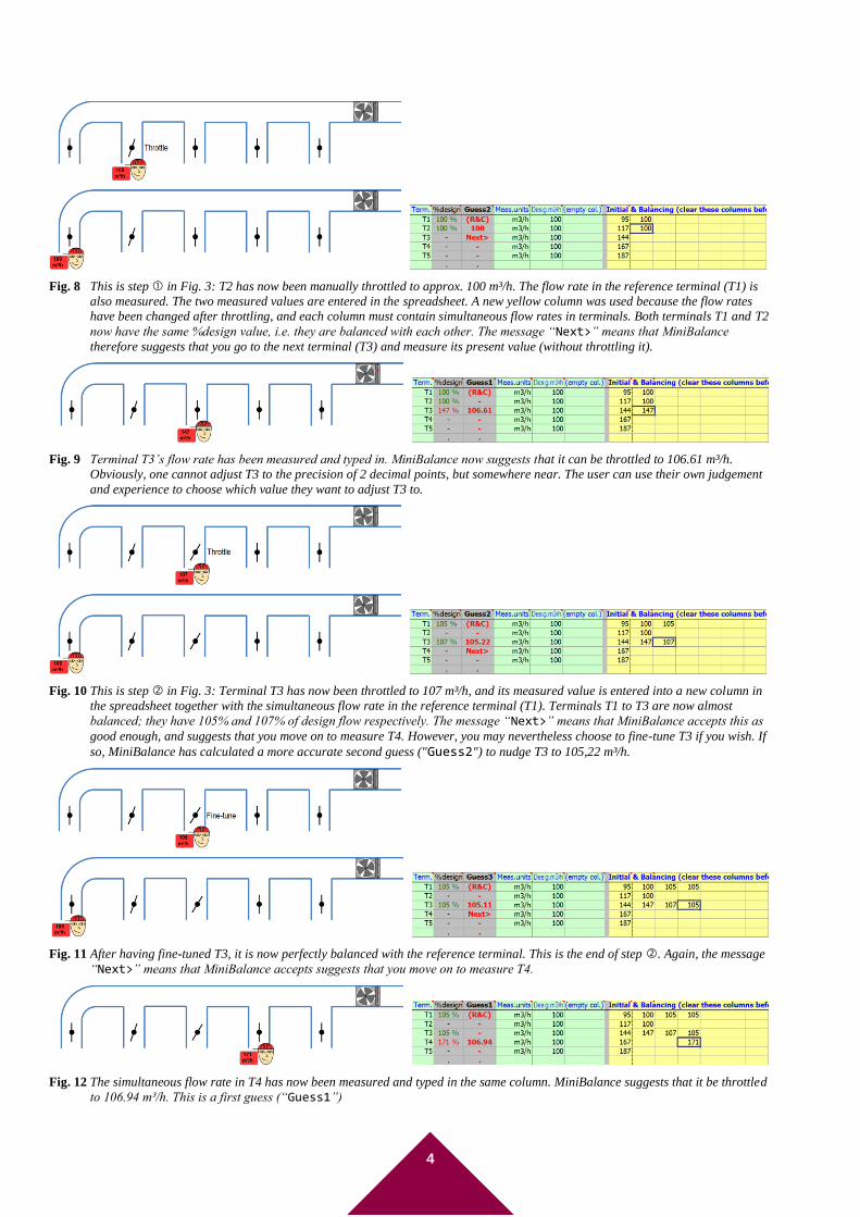
Fig. 8 This is step in Fig. 3: T2 has now been manually throttled to approx. 100 m³/h. The flow rate in the reference terminal (T1) is
also measured. The two measured values are entered in the spreadsheet. A new yellow column was used because the flow rates
have been changed after throttling, and each column must contain simultaneous flow rates in terminals. Both terminals T1 and T2
now have the same %design value, i.e. they are balanced with each other. The message “Next>” means that MiniBalance
therefore suggests that you go to the next terminal (T3) and measure its present value (without throttling it).
Fig. 9 Terminal T3’s flow rate has been measured and typed in. MiniBalance now suggests that it can be throttled to 106.61 m³/h.
Obviously, one cannot adjust T3 to the precision of 2 decimal points, but somewhere near. The user can use their own judgement
and experience to choose which value they want to adjust T3 to.
Fig. 10 This is step in Fig. 3: Terminal T3 has now been throttled to 107 m³/h, and its measured value is entered into a new column in
the spreadsheet together with the simultaneous flow rate in the reference terminal (T1). Terminals T1 to T3 are now almost
balanced; they have 105% and 107% of design flow respectively. The message “Next>” means that MiniBalance accepts this as
good enough, and suggests that you move on to measure T4. However, you may nevertheless choose to fine-tune T3 if you wish. If
so, MiniBalance has calculated a more accurate second guess ("Guess2") to nudge T3 to 105,22 m³/h.
Fig. 11 After having fine-tuned T3, it is now perfectly balanced with the reference terminal. This is the end of step . Again, the message
“Next>” means that MiniBalance accepts suggests that you move on to measure T4.
Fig. 12 The simultaneous flow rate in T4 has now been measured and typed in the same column. MiniBalance suggests that it be throttled
to 106.94 m³/h. This is a first guess (“Guess1”)
5
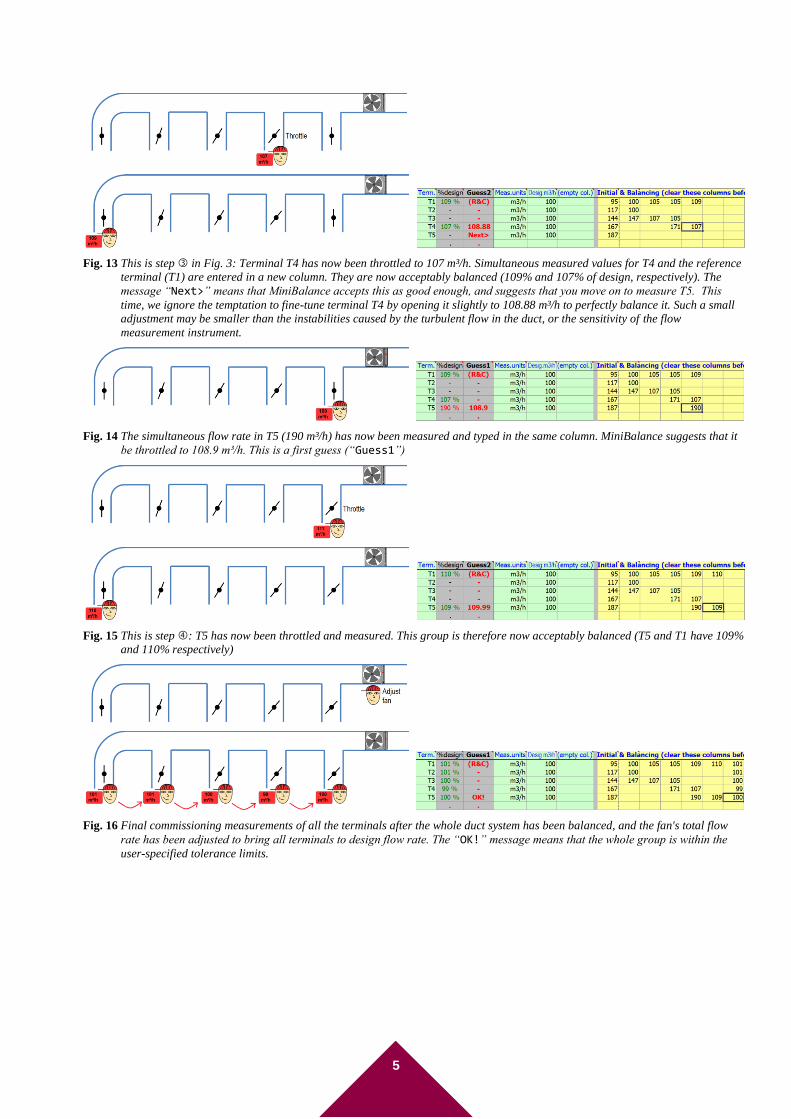
Fig. 13 This is step in Fig. 3: Terminal T4 has now been throttled to 107 m³/h. Simultaneous measured values for T4 and the reference
terminal (T1) are entered in a new column. They are now acceptably balanced (109% and 107% of design, respectively). The
message “Next>” means that MiniBalance accepts this as good enough, and suggests that you move on to measure T5. This
time, we ignore the temptation to fine-tune terminal T4 by opening it slightly to 108.88 m³/h to perfectly balance it. Such a small
adjustment may be smaller than the instabilities caused by the turbulent flow in the duct, or the sensitivity of the flow
measurement instrument.
Fig. 14 The simultaneous flow rate in T5 (190 m³/h) has now been measured and typed in the same column. MiniBalance suggests that it
be throttled to 108.9 m³/h. This is a first guess (“Guess1”)
Fig. 15 This is step : T5 has now been throttled and measured. This group is therefore now acceptably balanced (T5 and T1 have 109%
and 110% respectively)
Fig. 16 Final commissioning measurements of all the terminals after the whole duct system has been balanced, and the fan's total flow
rate has been adjusted to bring all terminals to design flow rate. The “OK!” message means that the whole group is within the
user-specified tolerance limits.
6
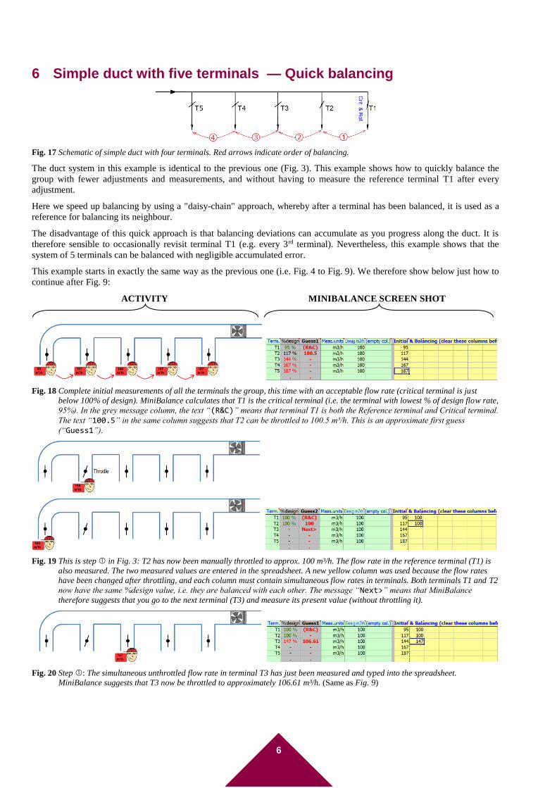
6 Simple duct with five terminals — Quick balancing
Fig. 17 Schematic of simple duct with four terminals. Red arrows indicate order of balancing.
The duct system in this example is identical to the previous one (Fig. 3). This example shows how to quickly balance the
group with fewer adjustments and measurements, and without having to measure the reference terminal T1 after every
adjustment.
Here we speed up balancing by using a "daisy-chain" approach, whereby after a terminal has been balanced, it is used as a
reference for balancing its neighbour.
The disadvantage of this quick approach is that balancing deviations can accumulate as you progress along the duct. It is
therefore sensible to occasionally revisit terminal T1 (e.g. every 3rd terminal). Nevertheless, this example shows that the
system of 5 terminals can be balanced with negligible accumulated error.
This example starts in exactly the same way as the previous one (i.e. Fig. 4 to Fig. 9). We therefore show below just how to
continue after Fig. 9:
ACTIVITY MINIBALANCE SCREEN SHOT
Fig. 18 Complete initial measurements of all the terminals the group, this time with an acceptable flow rate (critical terminal is just
below 100% of design). MiniBalance calculates that T1 is the critical terminal (i.e. the terminal with lowest % of design flow rate,
95%). In the grey message column, the text “(R&C)” means that terminal T1 is both the Reference terminal and Critical terminal.
The text “100.5” in the same column suggests that T2 can be throttled to 100.5 m³/h. This is an approximate first guess
(“Guess1”).
Fig. 19 This is step in Fig. 3: T2 has now been manually throttled to approx. 100 m³/h. The flow rate in the reference terminal (T1) is
also measured. The two measured values are entered in the spreadsheet. A new yellow column was used because the flow rates
have been changed after throttling, and each column must contain simultaneous flow rates in terminals. Both terminals T1 and T2
now have the same %design value, i.e. they are balanced with each other. The message “Next>” means that MiniBalance
therefore suggests that you go to the next terminal (T3) and measure its present value (without throttling it).
Fig. 20 Step : The simultaneous unthrottled flow rate in terminal T3 has just been measured and typed into the spreadsheet.
MiniBalance suggests that T3 now be throttled to approximately 106.61 m³/h. (Same as Fig. 9)
7
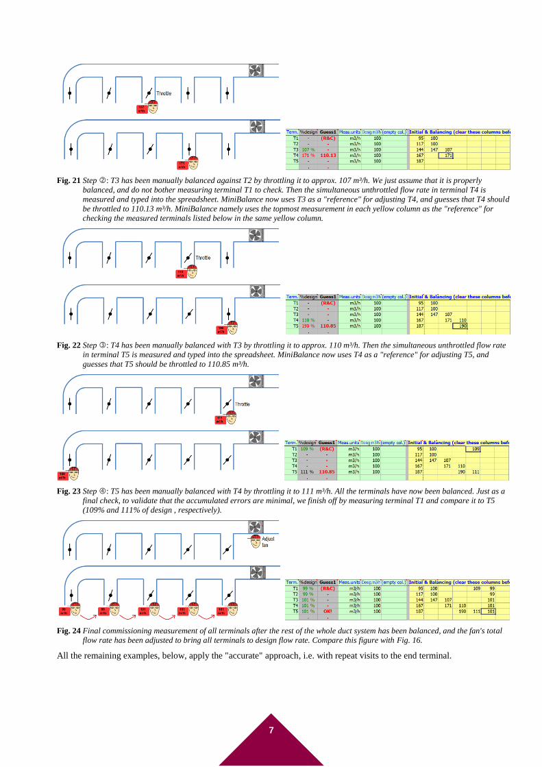
Fig. 21 Step : T3 has been manually balanced against T2 by throttling it to approx. 107 m³/h. We just assume that it is properly
balanced, and do not bother measuring terminal T1 to check. Then the simultaneous unthrottled flow rate in terminal T4 is
measured and typed into the spreadsheet. MiniBalance now uses T3 as a "reference" for adjusting T4, and guesses that T4 should
be throttled to 110.13 m³/h. MiniBalance namely uses the topmost measurement in each yellow column as the "reference" for
checking the measured terminals listed below in the same yellow column.
Fig. 22 Step : T4 has been manually balanced with T3 by throttling it to approx. 110 m³/h. Then the simultaneous unthrottled flow rate
in terminal T5 is measured and typed into the spreadsheet. MiniBalance now uses T4 as a "reference" for adjusting T5, and
guesses that T5 should be throttled to 110.85 m³/h.
Fig. 23 Step : T5 has been manually balanced with T4 by throttling it to 111 m³/h. All the terminals have now been balanced. Just as a
final check, to validate that the accumulated errors are minimal, we finish off by measuring terminal T1 and compare it to T5
(109% and 111% of design , respectively).
Fig. 24 Final commissioning measurement of all terminals after the rest of the whole duct system has been balanced, and the fan's total
flow rate has been adjusted to bring all terminals to design flow rate. Compare this figure with Fig. 16.
All the remaining examples, below, apply the "accurate" approach, i.e. with repeat visits to the end terminal.
8
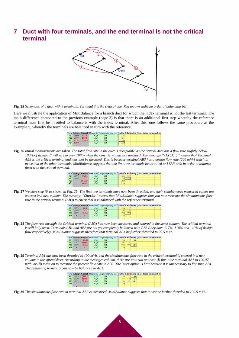
7 Duct with four terminals, and the end terminal is not the critical terminal
Fig. 25 Schematic of a duct with 4 terminals. Terminal 3 is the critical one. Red arrows indicate order of balancing [6].
Here we illustrate the application of MiniBalance for a branch duct for which the index terminal is not the last terminal. The
main difference compared to the previous example (page 3) is that there is an additional first step whereby the reference
terminal must first be throttled to balance it with the index terminal. After this, one follows the same procedure as the
example 5, whereby the terminals are balanced in turn with the reference.
Fig. 26 Initial measurements are taken. The total flow rate in the duct is acceptable, as the critical duct has a flow rate slightly below
100% of design. It will rise to over 100% when the other terminals are throttled. The message “(Crit.)” means that Terminal
AB3 is the critical terminal and must not be throttled. This is because terminal AB3 has a design flow rate (200 m³/h) which is
twice that of the other terminals. MiniBalance suggests that the first two terminals be throttled to 117.5 m³/h in order to balance
them with the critical terminal.
Fig. 27 We start step as shown in Fig. 25: The first two terminals have now been throttled, and their simultaneous measured values are
entered in a new column. The message ”Check>” means that MiniBalance suggests that you now measure the simultaneous flow
rate in the critical terminal (AB3) to check that it is balanced with the reference terminal.
Fig. 28 The flow rate through the Critical terminal (AB3) has now been measured and entered in the same column. The critical terminal
is still fully open. Terminals AB1 and AB2 are not yet completely balanced with AB3 (they have 117%, 118% and 110% of design
flow respectively). MiniBalance suggests therefore that terminal AB1 be further throttled to 99.5 m³/h.
Fig. 29 Terminal AB1 has now been throttled to 100 m³/h, and the simultaneous flow rate in the critical terminal is entered in a new
column in the spreadsheet. According to the messages column, there are now two options: (i) fine-tune terminal AB1 to 100.47
m³/h, or (ii) move on to measure the present flow rate in AB2. The latter option is best because it is unnecessary to fine tune AB1.
The remaining terminals can now be balanced to AB1.
Fig. 30 The simultaneous flow rate in terminal AB2 is measured. MiniBalance suggests that it now be further throttled to 100.5 m³/h.
9
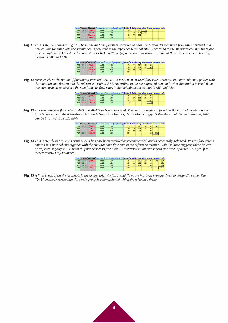
Fig. 31 This is step shown in Fig. 25: Terminal AB2 has just been throttled to near 100.5 m³/h. Its measured flow rate is entered in a
new column together with the simultaneous flow rate in the reference terminal AB1. According to the messages column, there are
now two options: (i) fine-tune terminal AB2 to 103.5 m³/h, or (ii) move on to measure the current flow rate in the neighbouring
terminals AB3 and AB4.
Fig. 32 Here we chose the option of fine tuning terminal AB2 to 103 m³/h. Its measured flow rate is entered in a new column together with
the simultaneous flow rate in the reference terminal AB1. According to the messages column, no further fine tuning is needed, so
one can move on to measure the simultaneous flow rates in the neighbouring terminals AB3 and AB4.
Fig. 33 The simultaneous flow rates in AB3 and AB4 have been measured. The measurements confirm that the Critical terminal is now
fully balanced with the downstream terminals (step in Fig. 25). MiniBalance suggests therefore that the next terminal, AB4,
can be throttled to 110.25 m³/h.
Fig. 34 This is step in Fig. 25: Terminal AB4 has now been throttled as recommended, and is acceptably balanced. Its new flow rate is
entered in a new column together with the simultaneous flow rate in the reference terminal. MiniBalance suggests that AB4 can
be adjusted slightly to 108.08 m³/h if one wishes to fine tune it. However it is unnecessary to fine tune it further. This group is
therefore now fully balanced.
Fig. 35 A final check of all the terminals in the group, after the fan’s total flow rate has been brought down to design flow rate. The
“OK!” message means that the whole group is commissioned within the tolerance limits.
10
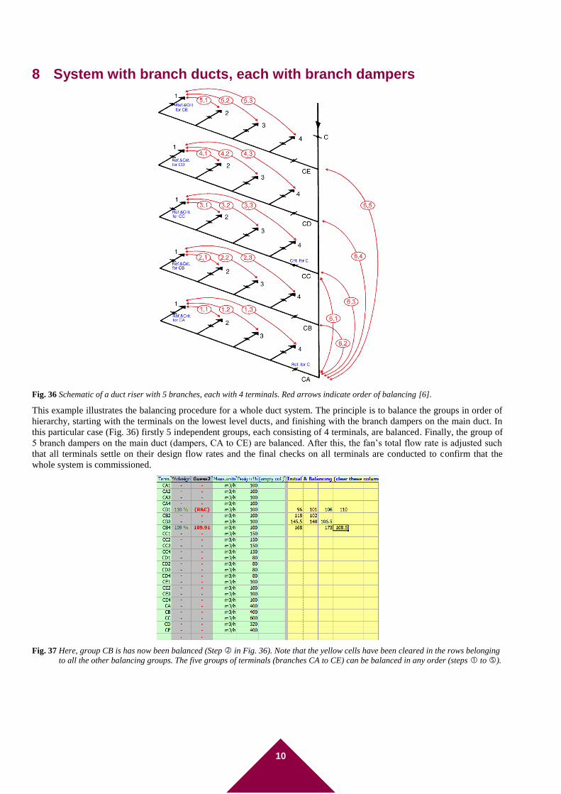
8 System with branch ducts, each with branch dampers
Fig. 36 Schematic of a duct riser with 5 branches, each with 4 terminals. Red arrows indicate order of balancing [6].
This example illustrates the balancing procedure for a whole duct system. The principle is to balance the groups in order of
hierarchy, starting with the terminals on the lowest level ducts, and finishing with the branch dampers on the main duct. In
this particular case (Fig. 36) firstly 5 independent groups, each consisting of 4 terminals, are balanced. Finally, the group of
5 branch dampers on the main duct (dampers, CA to CE) are balanced. After this, the fan’s total flow rate is adjusted such
that all terminals settle on their design flow rates and the final checks on all terminals are conducted to confirm that the
whole system is commissioned.
Fig. 37 Here, group CB is has now been balanced (Step in Fig. 36). Note that the yellow cells have been cleared in the rows belonging
to all the other balancing groups. The five groups of terminals (branches CA to CE) can be balanced in any order (steps to ).
11
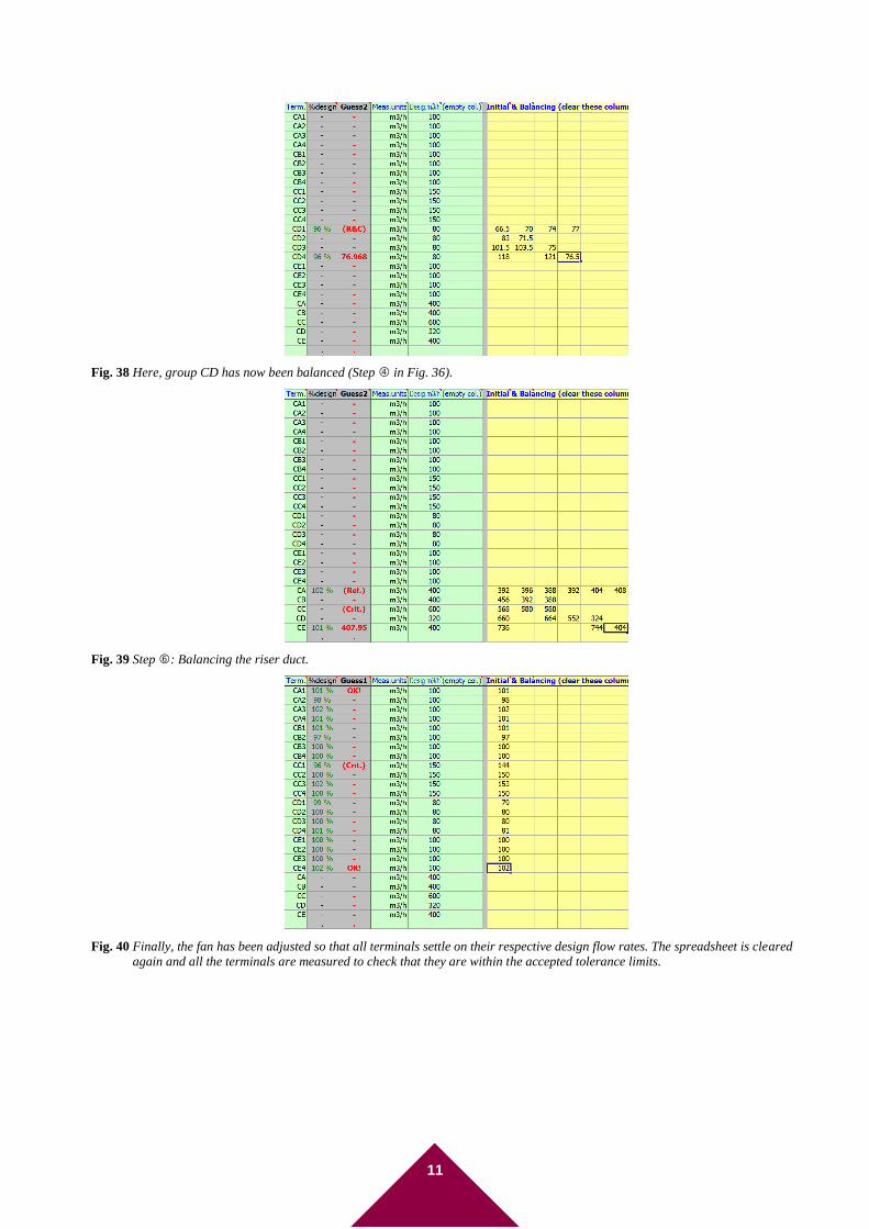
Fig. 38 Here, group CD has now been balanced (Step in Fig. 36).
Fig. 39 Step : Balancing the riser duct.
Fig. 40 Finally, the fan has been adjusted so that all terminals settle on their respective design flow rates. The spreadsheet is cleared
again and all the terminals are measured to check that they are within the accepted tolerance limits.
12
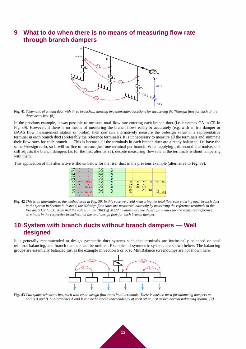
9 What to do when there is no means of measuring flow rate through branch dampers
Fig. 41 Schematic of a main duct with three branches, showing two alternative locations for measuring the %design flow for each of the
three branches. [6]
In the previous example, it was possible to measure total flow rate entering each branch duct (i.e. branches CA to CE in
Fig. 39). However, if there is no means of measuring the branch flows easily & accurately (e.g. with an iris damper or
BAAS flow measurement station or probe), then one can alternatively measure the %design value at a representative
terminal in each branch duct (preferably the reference terminals). It is unnecessary to measure all the terminals and summate
their flow rates for each branch — This is because all the terminals in each branch duct are already balanced, i.e. have the
same %design ratio, so it will suffice to measure just one terminal per branch. When applying this second alternative, one
still adjusts the branch dampers (as for the first alternative), despite measuring flow rate at the terminals without tampering
with them.
This application of this alternative is shown below for the riser duct in the previous example (alternative to Fig. 39).
Fig. 42 This is an alternative to the method used in Fig. 39. In this case we avoid measuring the total flow rate entering each branch duct
in the system in Section 8. Instead, the %design flow rates are measured indirectly by measuring the reference terminals in the
five ducts CA to CE. Note that the values in the “Desig.m3/h” column are the design flow rates for the measured reference
terminals in the respective branches, not the total design flow for each branch damper.
10 System with branch ducts without branch dampers — Well designed
It is generally recommended to design symmetric duct systems such that terminals are intrinsically balanced or need
minimal balancing, and branch dampers can be omitted. Examples of symmetric systems are shown below. The balancing
groups are essentially balanced just as the example in Section 5 or 6, so MiniBalance screendumps are not shown here.
Fig. 43 Two symmetric branches, each with equal design flow rates in all terminals. There is thus no need for balancing dampers at
points A and B. Sub-branches A and B can be balanced independently of each other, just as two normal balancing groups. [7]
13
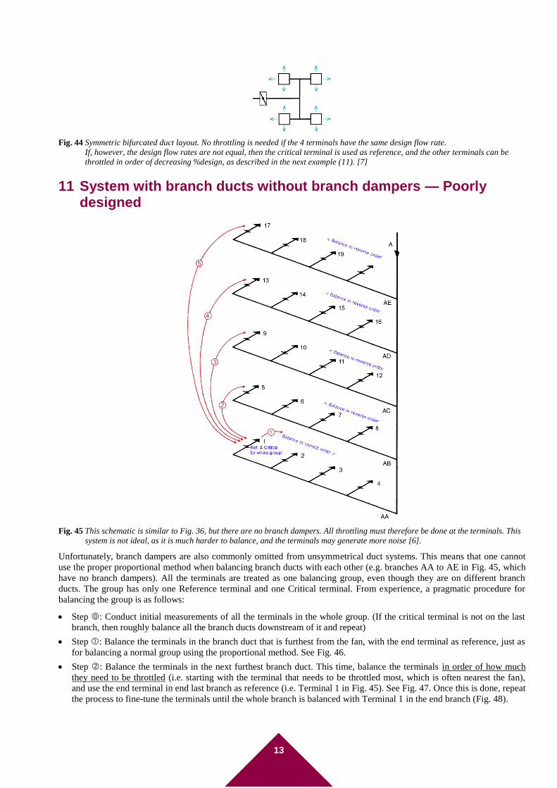
Fig. 44 Symmetric bifurcated duct layout. No throttling is needed if the 4 terminals have the same design flow rate.
If, however, the design flow rates are not equal, then the critical terminal is used as reference, and the other terminals can be
throttled in order of decreasing %design, as described in the next example (11). [7]
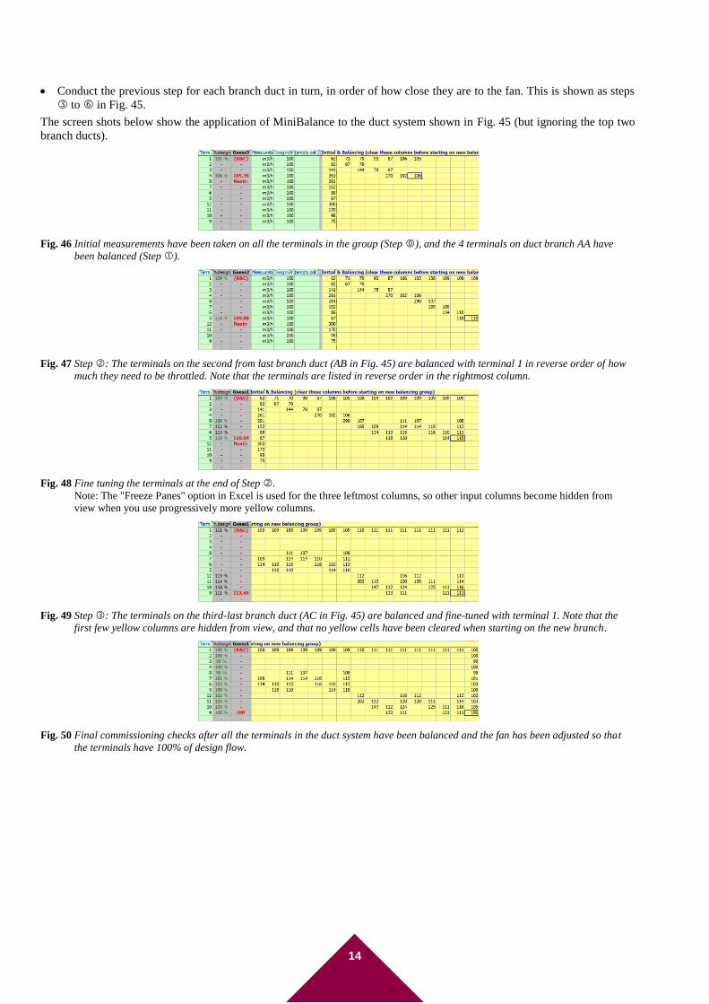
11 System with branch ducts without branch dampers — Poorly designed
Fig. 45 This schematic is similar to Fig. 36, but there are no branch dampers. All throttling must therefore be done at the terminals. This
system is not ideal, as it is much harder to balance, and the terminals may generate more noise [6].
Unfortunately, branch dampers are also commonly omitted from unsymmetrical duct systems. This means that one cannot
use the proper proportional method when balancing branch ducts with each other (e.g. branches AA to AE in Fig. 45, which
have no branch dampers). All the terminals are treated as one balancing group, even though they are on different branch
ducts. The group has only one Reference terminal and one Critical terminal. From experience, a pragmatic procedure for
balancing the group is as follows:
Step : Conduct initial measurements of all the terminals in the whole group. (If the critical terminal is not on the last
branch, then roughly balance all the branch ducts downstream of it and repeat)
Step : Balance the terminals in the branch duct that is furthest from the fan, with the end terminal as reference, just as
for balancing a normal group using the proportional method. See Fig. 46.
Step : Balance the terminals in the next furthest branch duct. This time, balance the terminals in order of how much
they need to be throttled (i.e. starting with the terminal that needs to be throttled most, which is often nearest the fan),
and use the end terminal in end last branch as reference (i.e. Terminal 1 in Fig. 45). See Fig. 47. Once this is done, repeat
the process to fine-tune the terminals until the whole branch is balanced with Terminal 1 in the end branch (Fig. 48).
14
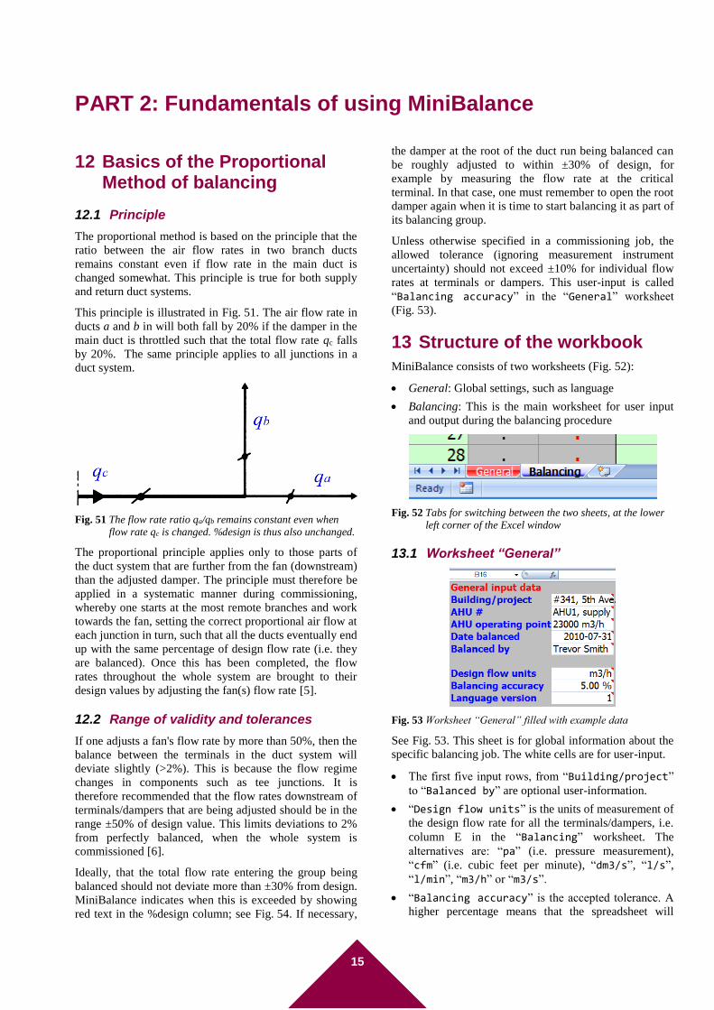
Conduct the previous step for each branch duct in turn, in order of how close they are to the fan. This is shown as steps
to in Fig. 45.
The screen shots below show the application of MiniBalance to the duct system shown in Fig. 45 (but ignoring the top two
branch ducts).
Fig. 46 Initial measurements have been taken on all the terminals in the group (Step ), and the 4 terminals on duct branch AA have
been balanced (Step ).
Fig. 47 Step : The terminals on the second from last branch duct (AB in Fig. 45) are balanced with terminal 1 in reverse order of how
much they need to be throttled. Note that the terminals are listed in reverse order in the rightmost column.
Fig. 48 Fine tuning the terminals at the end of Step .
Note: The "Freeze Panes" option in Excel is used for the three leftmost columns, so other input columns become hidden from
view when you use progressively more yellow columns.
Fig. 49 Step : The terminals on the third-last branch duct (AC in Fig. 45) are balanced and fine-tuned with terminal 1. Note that the
first few yellow columns are hidden from view, and that no yellow cells have been cleared when starting on the new branch.
Fig. 50 Final commissioning checks after all the terminals in the duct system have been balanced and the fan has been adjusted so that
the terminals have 100% of design flow.
15
PART 2: Fundamentals of using MiniBalance
12 Basics of the Proportional Method of balancing
12.1 Principle
The proportional method is based on the principle that the
ratio between the air flow rates in two branch ducts
remains constant even if flow rate in the main duct is
changed somewhat. This principle is true for both supply
and return duct systems.
This principle is illustrated in Fig. 51. The air flow rate in
ducts a and b in will both fall by 20% if the damper in the
main duct is throttled such that the total flow rate qc falls
by 20%. The same principle applies to all junctions in a
duct system.
Fig. 51 The flow rate ratio qa/qb remains constant even when
flow rate qc is changed. %design is thus also unchanged.
The proportional principle applies only to those parts of
the duct system that are further from the fan (downstream)
than the adjusted damper. The principle must therefore be
applied in a systematic manner during commissioning,
whereby one starts at the most remote branches and work
towards the fan, setting the correct proportional air flow at
each junction in turn, such that all the ducts eventually end
up with the same percentage of design flow rate (i.e. they
are balanced). Once this has been completed, the flow
rates throughout the whole system are brought to their
design values by adjusting the fan(s) flow rate [5].
12.2 Range of validity and tolerances
If one adjusts a fan's flow rate by more than 50%, then the
balance between the terminals in the duct system will
deviate slightly (>2%). This is because the flow regime
changes in components such as tee junctions. It is
therefore recommended that the flow rates downstream of
terminals/dampers that are being adjusted should be in the
range ±50% of design value. This limits deviations to 2%
from perfectly balanced, when the whole system is
commissioned [6].
Ideally, that the total flow rate entering the group being
balanced should not deviate more than ±30% from design.
MiniBalance indicates when this is exceeded by showing
red text in the %design column; see Fig. 54. If necessary,
the damper at the root of the duct run being balanced can
be roughly adjusted to within ±30% of design, for
example by measuring the flow rate at the critical
terminal. In that case, one must remember to open the root
damper again when it is time to start balancing it as part of
its balancing group.
Unless otherwise specified in a commissioning job, the
allowed tolerance (ignoring measurement instrument
uncertainty) should not exceed ±10% for individual flow
rates at terminals or dampers. This user-input is called
“Balancing accuracy” in the “General” worksheet
(Fig. 53).
13 Structure of the workbook
MiniBalance consists of two worksheets (Fig. 52):
General: Global settings, such as language
Balancing: This is the main worksheet for user input
and output during the balancing procedure
Fig. 52 Tabs for switching between the two sheets, at the lower
left corner of the Excel window
13.1 Worksheet “General”
Fig. 53 Worksheet “General” filled with example data
See Fig. 53. This sheet is for global information about the
specific balancing job. The white cells are for user-input.
The first five input rows, from “Building/project”
to “Balanced by” are optional user-information.
“Design flow units” is the units of measurement of
the design flow rate for all the terminals/dampers, i.e.
column E in the “Balancing” worksheet. The
alternatives are: “pa” (i.e. pressure measurement),
“cfm” (i.e. cubic feet per minute), “dm3/s”, “l/s”,
“l/min”, “m3/h” or “m3/s”.
“Balancing accuracy” is the accepted tolerance. A
higher percentage means that the spreadsheet will
16
accept a higher percentage deviation from ideally
balanced flow rate at each individual terminal/damper.
Note that the total balancing error is the sum of the
tolerance and the measurement error.
“Language version” is a number between 1
(English) and 9 (Spanish). See the table at the end of
this paper.
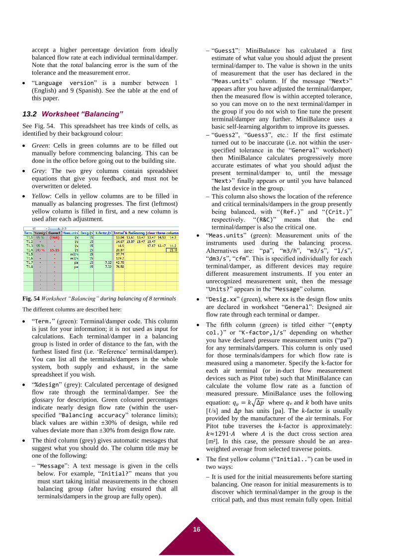
13.2 Worksheet “Balancing”
See Fig. 54. This spreadsheet has tree kinds of cells, as
identified by their background colour:
Green: Cells in green columns are to be filled out
manually before commencing balancing. This can be
done in the office before going out to the building site.
Grey: The two grey columns contain spreadsheet
equations that give you feedback, and must not be
overwritten or deleted.
Yellow: Cells in yellow columns are to be filled in
manually as balancing progresses. The first (leftmost)
yellow column is filled in first, and a new column is
used after each adjustment.
Fig. 54 Worksheet “Balancing” during balancing of 8 terminals
The different columns are described here:
“Term.” (green): Terminal/damper code. This column
is just for your information; it is not used as input for
calculations. Each terminal/damper in a balancing
group is listed in order of distance to the fan, with the
furthest listed first (i.e. ‘Reference’ terminal/damper).
You can list all the terminals/dampers in the whole
system, both supply and exhaust, in the same
spreadsheet if you wish.
“%design” (grey): Calculated percentage of designed
flow rate through the terminal/damper. See the
glossary for description. Green coloured percentages
indicate nearly design flow rate (within the user-
specified “Balancing accuracy” tolerance limits);
black values are within ±30% of design, while red
values deviate more than ±30% from design flow rate.
The third column (grey) gives automatic messages that
suggest what you should do. The column title may be
one of the following:
“Message”: A text message is given in the cells
below. For example, “Initial?” means that you
must start taking initial measurements in the chosen
balancing group (after having ensured that all
terminals/dampers in the group are fully open).
“Guess1”: MiniBalance has calculated a first
estimate of what value you should adjust the present
terminal/damper to. The value is shown in the units
of measurement that the user has declared in the
“Meas.units” column. If the message “Next>”
appears after you have adjusted the terminal/damper,
then the measured flow is within accepted tolerance,
so you can move on to the next terminal/damper in
the group if you do not wish to fine tune the present
terminal/damper any further. MiniBalance uses a
basic self-learning algorithm to improve its guesses.
“Guess2”, “Guess3”, etc.: If the first estimate
turned out to be inaccurate (i.e. not within the user-
specified tolerance in the “General” worksheet)
then MiniBalance calculates progressively more
accurate estimates of what you should adjust the
present terminal/damper to, until the message
“Next>” finally appears or until you have balanced
the last device in the group.
This column also shows the location of the reference
and critical terminals/dampers in the group presently
being balanced, with “(Ref.)” and “(Crit.)”
respectively. “(R&C)” means that the end
terminal/damper is also the critical one.
“Meas.units” (green): Measurement units of the
instruments used during the balancing process.
Alternatives are: “pa”, “m3/h”, “m3/s”, “l/s”,
“dm3/s”, “cfm”. This is specified individually for each
terminal/damper, as different devices may require
different measurement instruments. If you enter an
unrecognized measurement unit, then the message
“Units?” appears in the “Message” column.
“Desig.xx” (green), where xx is the design flow units
are declared in worksheet “General”: Designed air
flow rate through each terminal or damper.
The fifth column (green) is titled either “(empty col.)” or “K-factor,l/s” depending on whether
you have declared pressure measurement units (“pa”)
for any terminals/dampers. This column is only used
for those terminals/dampers for which flow rate is
measured using a manometer. Specify the k-factor for
each air terminal (or in-duct flow measurement
devices such as Pitot tube) such that MiniBalance can
calculate the volume flow rate as a function of
measured pressure. MiniBalance uses the following
equation: 𝑞𝑣 = 𝑘√∆𝑝 where 𝑞𝑣 and 𝑘 both have units
[ℓ/s] and Δ𝑝 has units [pa]. The k-factor is usually
provided by the manufacturer of the air terminals. For
Pitot tube traverses the k-factor is approximately:
𝑘≈1291·𝐴 where 𝐴 is the duct cross section area
[m²]. In this case, the pressure should be an area-
weighted average from selected traverse points.
The first yellow column (“Initial..”) can be used in
two ways:
It is used for the initial measurements before starting
balancing. One reason for initial measurements is to
discover which terminal/damper in the group is the
critical path, and thus must remain fully open. Initial
17
measurements should include all the terminals/
dampers in just one balancing group (see Fig. 7). All
other cells in all the yellow columns shall be cleared.
This tells MiniBalance which terminals/dampers
belong to the group presently being balanced. When
balancing is completed for that group, you should
clear all the yellow cells in the spreadsheet and start
again with measurements of a new group of
terminals/dampers (see the example in section 8).
These initial measurements generally start with all
the terminals/dampers in the group being fully open.
Alternatively, this column can be used just for
control-measurements of the whole, or any part of,
the duct system. In this case the dampers are
obviously not tampered with before measuring.
The second and consecutive yellow columns are for
typing in measurements during the actual balancing
process. As mentioned above, all cells in the yellow
columns shall remain empty, apart from the cells that
belong to the present balancing group. Use a new
column after each adjustment. A terminal/damper can
be adjusted any number of times (fine tuning), each
time with a new column. Normally you enter two or
three measurements in each column: (1) the terminal/
damper being balanced, (2) the simultaneous
measurement at the Reference terminal/damper, and
(3) if the message “Next>” appears then give the
simultaneous measurement in the next
terminal/damper in the list. You do not strictly have to
use the end terminal/damper as the reference (though
this is normally most accurate). The only requirement
is that it is a terminal/damper in the group that is
further away from the fan. See, for example, the quick
balancing method on page 6. You may enter any
number of simultaneous measurements per column if
you wish. MiniBalance shows the calculated %design
value for all these measured terminals/dampers.
14 Acknowledgements
Writing this user guide was in part financed by Enova SF.
15 Bibliography
[1] ASHRAE Standard 111-1988 ‘Practices for
Measurement, Testing, Adjusting and Balancing of
Building Heating, Ventilation, Air Conditioning, and
Refrigeration Systems’. www.ashrae.org
[2] Parsloe, C. ‘Commissioning Air Systems.
Application procedures for buildings’ BSRIA
publication AG 3/89.3 (2001).
www.bsria.co.uk
[3] ‘Commissioning Code A: Air Distribution Systems’,
CIBSE, 1996/2004.
www.cibse.org
[4] ‘HVAC Systems Testing, Adjusting and Balancing’
SMACNA handbook 1780. August 2002.
www.smacna.org
[5] Mark J. Limb, ‘Balancing Ventilation Systems: An
Annotated Bibliography’, AIVC publication BIB11,
2001
[6] Thunshelle, K. ’VENT 64.103 Innregulering etter
proporsjonalmetoden’. Oslo : SINTEF Building &
Infrastructure. 2002
[7] Thunshelle, K. 'VENT 64.101 Utforming av anlegg
for god innregulering: Prosjekteringsveiledning'.
Oslo : SINTEF Building & Infrastructure. 2002
Full text description Langages used in software:
English Czech Danish Dutch French Greek Korean Norwegian Spanish
Language name English Česky Dansk Nederlands Francais Ελληνικά 한국어 Norsk Español
General input data General input data Obecné vstupní data
Generelle inputdata Algemene invoergegevens
Données générales Δεδομένα εισόδου 일반 입력 데이터 Generell inndata Entrada general de datos
Building / project name or description Building/project Bodova/projekt Bygning/projekt Gebouw/project Bâtiment / projet Κτίριο/έργου 건물/프로젝트 Bygning/prosjekt Edificio / proyecto
Description of duct system being balanced, i.e.air handling unit (e.g. number/code), and whether it is the supply or exhaust duct system
AHU # Větrací jednotka #
System # MVU # Groupe n° ΜΔΑ # 시스템 수 Anlegg # Numero de unidades de tratamiento de aire (UTA)
Air handling unit setting during balancing: e.g. flow rate, fan speed, pressure rise, or variable frequency drive setting)
AHU operating point Provozní bod Aggregat innstilling MVU volume Position de réglage Σημείο λειτουργίας ΜΔΑ 시스템 운전포인트 Aggregat innstilling ¿punto de operación de la UTA?
Date when balancing was conducted Date balanced Datum Dato innregulert Datum Date d'équilibrage Ημερομηνία 날짜 Dato innregulert Fecha del equilibrado
Name of person who conducted the balancing Balanced by Vyvážena, jméno Utført av Ingesteld door Nom de l'opérateur Εξισορροπημένο από 밸런싱 수행자 Utført av Nombre de la persona que realizó el equilibrado
SI units of design flow rate Design flow units Náv. jednotka průtoku
Prosj.måleenhet Gebruikte eenheid ontwerp
Unité de débit Μονάδες παροχής σχεδιασμού 설계유량 단위 Prosj.måleenhet Unidades SI de diseño del flujo
Balancing accuracy (percentage) Balancing accuracy Přesnost vyvážení
Innreg.nøyaktighet Nauwkeurigheid instelling
Précision requise Ακρίβεια εξισορρόπησης 밸런싱 정확도 Innreg.nøyaktighet Precisión del equilibrado
Different measurement units available (alternatives: pa, cfm, dm3/s, l/s, l/min, m3/h, m3/s)
(alternativy: pa, cfm, dm3/s, l/s, l/min, m3/h, m3/s)
(alternativ: pa, cfm, dm3/s, l/s, l/min, m3/h, m3/s)
(alternatieven: pa, cfm, dm3/s, l/s, l/min, m3/h, m3/s)
(Alternatives: pa, cfm, dm3/s, l/s, l/min, m3/h, m3/s)
(εναλλακτικά: pa, cfm, dm3/s, l/s, l/min, m3/h, m3/s)
(대체 단위: pa, cfm,
dm3/s, l/s, l/min, m3/h, m3/s)
(alternativer: pa, cfm, dm3/s, l/s, l/min, m3/h, m3/s)
(alternativas: pa, cfm, dm3/s, l/s, l/min, m3/h, m3/s)
Abbreviation for "Air terminal (or damper)" Term. Klapka Spjeld Ventiel Bouch ΤΔΑ 터미널(댐퍼) Spjeld Term.aire
Abbreviation for "% of design flow rate" %design %/Návrh %/Prosj. %/Ontwerp. %/Proj %/Σχέδιο 설계유량 비율 %/Prosj. %/Diseño
"Message" to the user Message Message Medling Bericht Message Μήνυμα 메시지 Medling Mensaje
Calculated "guess" by software Guess Odhad Estim. Raden Estim. Εκτίμηση 예측 Estim. Estim.
Measurement units Meas.units Jed. Måleenhet Eenheid Unité Μονάδες μέτρησης 측정 단위 Måleenhet Unid.de.Med
Abbreviation for "Design flow rate" Desig. Návrh, Prosj. Ontwerp, Design, Σχεδ. 설계유량: Prosj. Diseño,
K-factor for air terminals that are balanced by measuring pressure drop, and using the following equation: Flow rate [ℓ/s] = K·√(Δp)
K-factor: l/s K: (l/s)? K-faktor: l/s K-fact? K-fact.: l/s Συντελεστής Κ K-factor: l/s K-faktor: l/s factor-K: l/s
(empty/blank column) (empty col.) (mezera) (tom kolonne) (lege kolom) (col. vide) Κενή στήλη (공란) (tom kolonne) (colum.vacia)
Initial & Balancing (clear these columns before starting on new string)
Initial & Balancing (clear these columns before starting on new string)
Počátek & Vyvážení (na počátku vymazat sloupce
Orient. & Innregulering (tøm disse gule kolonner før hver streng)
Initieel & instellingen(maak de colummen leeg voor aanvang)
Initial & Equilibrage (videz ces colonnes avant de commencer)
Αρχική τιμή και Εξισορρόπηση (Καθαρίστε αυτές τις στήλες πριν εισάγετε οτιδήποτε νέο)
초기&밸런싱(새로운
문장을 입력하기 전에
이 열을 지우시오)
Orient. & Innregulering (tøm disse gule kolonner før hver streng)
Inicial & Equilibrado (Borrar estas columnas antes de empezar una nueva serie)
"Do not change this worksheet !" Do not change this worksheet !
Neměňte tento list!
Dette arket skal ikke endres !
Breng geen veranderingen aan in dit werkblad
Ne pas modifier cette feuille de travail!
Μην αλλάξετε αυτό το φύλλο εργασίας!
이 워크시트를
변경하지 마십시오!
Dette arket skal ikke endres !
No cambiar esta hoja de cálculo!
When the reference terminal is also critical terminal. R=reference terminal, which is the terminal at the end of the duct. C=critical terminal, which will be left fully open.
(R&C) (R&C) (R&K) (R&C) (R&C) (Α&κ) 참조/임계 (R&I) (R&C)
Abbreviation for "Reference" terminal/damper, i.e. the terminal/damper at the end of the duct, furthest from fan
(Ref.) (R) (Ref.) (R) (R) (Αναφ.) 참조 (R) (R)
Abbreviation for "Critical" terminal/damper, i.e. the “critical path” terminal/damper for the balancing group, defined as the one that will be left fully open after balancing
(Crit.) (C) (Krit.) (C) (C) (κρί.) 임계 (I) (C)
"Units" of measurement ? Units? Jednotka? Enhet? Eenheid? Unités? Μονάδες? 단위? Enhet? ¿Unidades?
Short for "K-factor", where k is the flow coefficient, where: Flow rate [ℓ/s] = K·√(Δp)
K-fact? K? K-fakt? K-fact? K-fact? Συντ. Κ? K-fact? K-fakt? ¿Fact-K?
"Design?" for design flow rate Design? Návrh? Prosj? Ontwerp. Projet? Σχεδιασμός? 설계유량? Prosj? ¿Diseño?
"Initial?" for the first orienting measuremens that are conducted with all terminals fully open
Initial? Poč.? Orient? Initieel? Init.? Αρχική? 초기측정치? Orient? ¿Inicial?
"Next>" flags the next terminal to be measured Next> Další> Måle> Volgende Suite> Επόμενο> 다음> Måle> Siguiente>
"(no more rows)" (no more rows) (žádné další řádky)
(ikke flere rad) (niet meer rijen) (pas plus de lignes) (δεν υπάρχουν περισσότερες σειρές)
(더 이상의 행이
없습니다) (ikke flere rad) (no hay más filas)
"(no more columns)" (no more columns) (žádné další sloupce)
(ikke flere kolonner) (niet meer kolommen)
(pas plus de colonnes)
(δεν υπάρχουν περισσότερες στήλες)
(더 이상의 열이
없습니다) (ikke flere kolonner) (no hay más columnas)
"Check>" marks a terminal for which the flow rate should be measured and checked
Check> Kontr.> Sjekk> Contr Contr.> Έλεγχος> 확인> Sjekk> Control>


![User guide for the balancing spread sheet MiniBalance...guidebook on commissioning/TAB (testing, adjusting & balancing) of duct systems, such as references [1] to [4]. The literature](https://img.pdfslide.us/doc/110x75/601e812c080755079b649f41/user-guide-for-the-balancing-spread-sheet-minibalance-guidebook-on-commissioningtab.jpg)