Embed Size (px)
Citation preview
User Guide for Cisco Video Assurance Management Solution 1.5December 17, 2008
Americas HeadquartersCisco Systems, Inc.170 West Tasman DriveSan Jose, CA 95134-1706 USAhttp://www.cisco.comTel: 408 526-4000
800 553-NETS (6387)Fax: 408 527-0883
Text Part Number: OL-16498-01

THE SPECIFICATIONS AND INFORMATION REGARDING THE PRODUCTS IN THIS MANUAL ARE SUBJECT TO CHANGE WITHOUT NOTICE. ALL STATEMENTS, INFORMATION, AND RECOMMENDATIONS IN THIS MANUAL ARE BELIEVED TO BE ACCURATE BUT ARE PRESENTED WITHOUT WARRANTY OF ANY KIND, EXPRESS OR IMPLIED. USERS MUST TAKE FULL RESPONSIBILITY FOR THEIR APPLICATION OF ANY PRODUCTS.
THE SOFTWARE LICENSE AND LIMITED WARRANTY FOR THE ACCOMPANYING PRODUCT ARE SET FORTH IN THE INFORMATION PACKET THAT SHIPPED WITH THE PRODUCT AND ARE INCORPORATED HEREIN BY THIS REFERENCE. IF YOU ARE UNABLE TO LOCATE THE SOFTWARE LICENSE OR LIMITED WARRANTY, CONTACT YOUR CISCO REPRESENTATIVE FOR A COPY.
The Cisco implementation of TCP header compression is an adaptation of a program developed by the University of California, Berkeley (UCB) as part of UCB’s public domain version of the UNIX operating system. All rights reserved. Copyright © 1981, Regents of the University of California.
NOTWITHSTANDING ANY OTHER WARRANTY HEREIN, ALL DOCUMENT FILES AND SOFTWARE OF THESE SUPPLIERS ARE PROVIDED “AS IS” WITH ALL FAULTS. CISCO AND THE ABOVE-NAMED SUPPLIERS DISCLAIM ALL WARRANTIES, EXPRESSED OR IMPLIED, INCLUDING, WITHOUT LIMITATION, THOSE OF MERCHANTABILITY, FITNESS FOR A PARTICULAR PURPOSE AND NONINFRINGEMENT OR ARISING FROM A COURSE OF DEALING, USAGE, OR TRADE PRACTICE.
IN NO EVENT SHALL CISCO OR ITS SUPPLIERS BE LIABLE FOR ANY INDIRECT, SPECIAL, CONSEQUENTIAL, OR INCIDENTAL DAMAGES, INCLUDING, WITHOUT LIMITATION, LOST PROFITS OR LOSS OR DAMAGE TO DATA ARISING OUT OF THE USE OR INABILITY TO USE THIS MANUAL, EVEN IF CISCO OR ITS SUPPLIERS HAVE BEEN ADVISED OF THE POSSIBILITY OF SUCH DAMAGES.
CCDE, CCENT, Cisco Eos, Cisco Lumin, Cisco Nexus, Cisco StadiumVision, Cisco TelePresence, the Cisco logo, DCE, and Welcome to the Human Network are trademarks; Changing the Way We Work, Live, Play, and Learn and Cisco Store are service marks; and Access Registrar, Aironet, AsyncOS, Bringing the Meeting To You, Catalyst, CCDA, CCDP, CCIE, CCIP, CCNA, CCNP, CCSP, CCVP, Cisco, the Cisco Certified Internetwork Expert logo, Cisco IOS, Cisco Press, Cisco Systems, Cisco Systems Capital, the Cisco Systems logo, Cisco Unity, Collaboration Without Limitation, EtherFast, EtherSwitch, Event Center, Fast Step, Follow Me Browsing, FormShare, GigaDrive, HomeLink, Internet Quotient, IOS, iPhone, iQ Expertise, the iQ logo, iQ Net Readiness Scorecard, iQuick Study, IronPort, the IronPort logo, LightStream, Linksys, MediaTone, MeetingPlace, MeetingPlace Chime Sound, MGX, Networkers, Networking Academy, Network Registrar, PCNow, PIX, PowerPanels, ProConnect, ScriptShare, SenderBase, SMARTnet, Spectrum Expert, StackWise, The Fastest Way to Increase Your Internet Quotient, TransPath, WebEx, and the WebEx logo are registered trademarks of Cisco Systems, Inc. and/or its affiliates in the United States and certain other countries.
All other trademarks mentioned in this document or Website are the property of their respective owners. The use of the word partner does not imply a partnership relationship between Cisco and any other company. (0807R)
Any Internet Protocol (IP) addresses used in this document are not intended to be actual addresses. Any examples, command display output, and figures included in the document are shown for illustrative purposes only. Any use of actual IP addresses in illustrative content is unintentional and coincidental.
User Guide for Cisco Video Assurance Management Solution 1.5 © 2008 Cisco Systems, Inc. All rights reserved.
OL-16498-01
C O N T E N T S
Preface vii
Document Revision History vii
Objectives viii
Audience viii
Document Organization viii
Related Documentation ixCisco Product Documentation ix
Cisco Active Network Abstraction ixCisco Multicast Manager xi
Cisco Routers and Switches xii
Cisco Info Center xiii
Cisco Internet Protocol Television (IPTV) Solutions xiii
Video Probe Documentation xiv
Document Conventions xiv
Obtaining Documentation and Submitting a Service Request xv
C H A P T E R 1 Overview 1-1
License Information 1-1
Introduction to Cisco VAMS 1.5 1-2
Cisco VAMS 1.5 Network Topology 1-2
Cisco VAMS 1.5 in a Wireline Network 1-4
Cisco VAMS 1.5 in a Cable Network 1-5
Cisco VAMS Solution Components 1-6
Solution Component Versions 1-7
Cisco Multicast Manager 2.5.4 1-8
Cisco Multicast Manager 2.5.4 Hardware Components 1-8
Cisco Multicast Manager 2.5.4 Software Components 1-10
Cisco Info Center 1-12
IBM Tivoli Netcool/OMNIbus and ObjectServer 1-12
IBM Tivoli Netcool/Webtop 1-14
IBM Tivoli Netcool/Impact 1-15
IBM Tivoli Business Service Manager 1-15
IBM Tivoli Netcool GUI Foundation 1-16
IBM Tivoli Netcool Probes 1-16
iiiUser Guide for Cisco Video Assurance Management Solution 1.5
Contents
Rules Files 1-16
Cisco ANA 3.6.3 1-17
Cisco ANA 3.6.3 Hardware Components 1-17
Cisco ANA 3.6.3 Software Components 1-20
Third-Party Video Probes 1-26
Cisco VAMS 1.5 Solution Software Description 1-27
Cisco Advanced Services Support for VAMS 1-28
Cisco Lifecycle Approach 1-28
Prepare Phase 1-29
Plan Phase 1-30
Design Phase 1-30
Implement Phase 1-30
C H A P T E R 2 Preinstallation 2-1
Prerequisites 2-1
Install and Configure Prerequisite Hardware and Software Solution Components 2-2
C H A P T E R 3 Installing the Cisco Video Assurance Management Solution 1.5 3-1
Before You Install 3-1
Release Notes 3-1
Install the Cisco VAMS 1.5 Software 3-1
C H A P T E R 4 Uninstalling the Cisco Video Assurance Management Solution 1.5 4-1
Uninstall Cisco VAMS 1.5 4-1
C H A P T E R 5 Configuring the Components of the Cisco Video Assurance Management Solution 1.5 5-1
Create VNEs 5-2
Add Solution Components to the Cisco ANA Network Map 5-4
Configure the CMM 5-5
General CMM Configuration 5-5
Setting Up Troubleshooting Configuration for IP Multicast 5-6
Configuring BPS/PPS Threshold Monitoring 5-6
Configuring Tree Polling 5-8
Configuring Health Checks 5-11
Configuring IP Multicast Heartbeat Monitoring 5-13
Configure Video Probes 5-14
Bridge Technologies Video Probe 5-14
IneoQuest Video Probe 5-14
ivUser Guide for Cisco Video Assurance Management Solution 1.5
OL-16498-01
Contents
Mixed Signals Video Probe 5-15
PixelMetrix Video Probe 5-15
Tektronix Video Probe 5-15
Run the Setup for IPTV Script 5-15
Run the Cleanup from IPTV Script 5-16
CIC Configuration 5-16
Prerequisites 5-16
Installation of Cisco ANA to Netcool Adapter 5-17
Log Level Configuration 5-18
Installing the IBM Tivoli Netcool Rules Files 5-19
Installing IBM Tivoli Netcool View For ANA 5-21
C H A P T E R 6 Troubleshooting with the Cisco Video Assurance Management Solution 1.5 6-1
Monitoring ANA, CMM, and Video Probe Events with TBSM 6-1
Monitoring ANA, CMM, and Video Probe Events with Netcool/Webtop 6-4
Advanced Troubleshooting with CMM and TBSM 6-6
Monitoring Multicast Tree Changes (Tree Polling) 6-7
Monitoring Multicast Tree Changes with CIC 6-8
Monitoring Multicast Tree Changes with CMM 6-9
Monitoring IP Multicast Heartbeat 6-11
Monitoring Heartbeat Events with CIC/TBSM 6-12
Monitoring Heartbeat Events with CMM 6-13
Performing Health Checks 6-14
Monitoring PPS/BPS Thresholds 6-15
Monitoring PPS/BPS Thresholds in CIC TBSM/Webtop 6-15
Monitoring Threshold Events with CMM 6-16
Monitoring and Troubleshooting in the Wireline Network 6-19
Monitoring and Troubleshooting in the Cable Network 6-19
Troubleshooting with Cisco ANA 6-20
Fault Management 6-20
ANA NetworkVision 6-21
ANA EventVision 6-21
A P P E N D I X A Trap Definitions A-1
CMM A-1
Cisco 7600, Catalyst 6500, CRS-1, and Catalyst 4948 Devices A-3
Bridge Technologies Video Probe A-3
Ethernet Alarms A-3
vUser Guide for Cisco Video Assurance Management Solution 1.5
OL-16498-01
Contents
ETR (290) Alarms A-4
SYS (System) Events A-4
IneoQuest Video Probe A-5
Mixed Signals Video Probe A-5
PixelMetrix Video Probe A-7
Tektronix Video Probe A-7
Performance Metrics A-8
A P P E N D I X B End User License Agreement Supplement B-1
ADDITIONAL LICENCE RESTRICTIONS B-3
DESCRIPTION OF OTHER RIGHTS AND LIMITATIONS B-4
G L O S S A R Y
I N D E X
viUser Guide for Cisco Video Assurance Management Solution 1.5
OL-16498-01

Preface
This preface describes the objectives, audience, organization, and conventions of the User Guide for Cisco Video Assurance Management Solution 1.5.
Note Use this document along with the documents listed in the “Related Documentation” section on page ix.
This preface contains:
• Document Revision History, page vii
• Objectives, page viii
• Audience, page viii
• Document Organization, page viii
• Related Documentation, page ix
• Document Conventions, page xiv
• Obtaining Documentation and Submitting a Service Request, page xv
In this guide, each installation and configuration bases its procedures on Cisco product documentation with corresponding references made to specified product documentation guides (supplied during site installation or available online at cisco.com). Refer to these guides whenever requested. Each reference will call out the required procedure and the section of the guide that you will need.
Document Revision HistoryThe following Document Revision History table records technical changes to this document. The table shows the document revision number for the change, the date of the change, and a brief summary of the change.
Revision Date Change Summary
OL-16498-01 December 17, 2008 Initial release.
viiUser Guide for Cisco Video Assurance Management Solution 1.5
OL-16498-01
Preface
ObjectivesThis guide describes the architecture, the components, and the processes necessary for the design and implementation of the Cisco Video Assurance Management Solution (Cisco VAMS), Release 1.5.
AudienceThe target audience for the Cisco VAMS guide should have a basic knowledge of network management products, and experience with the installation and acceptance of these products covered by this solution.
In addition, the user should understand the procedures to upgrade and troubleshoot video systems and Ethernet switches.
Note This document addresses Cisco components only. It does not discuss how to implement third-party components optionally supported for video management capabilities.
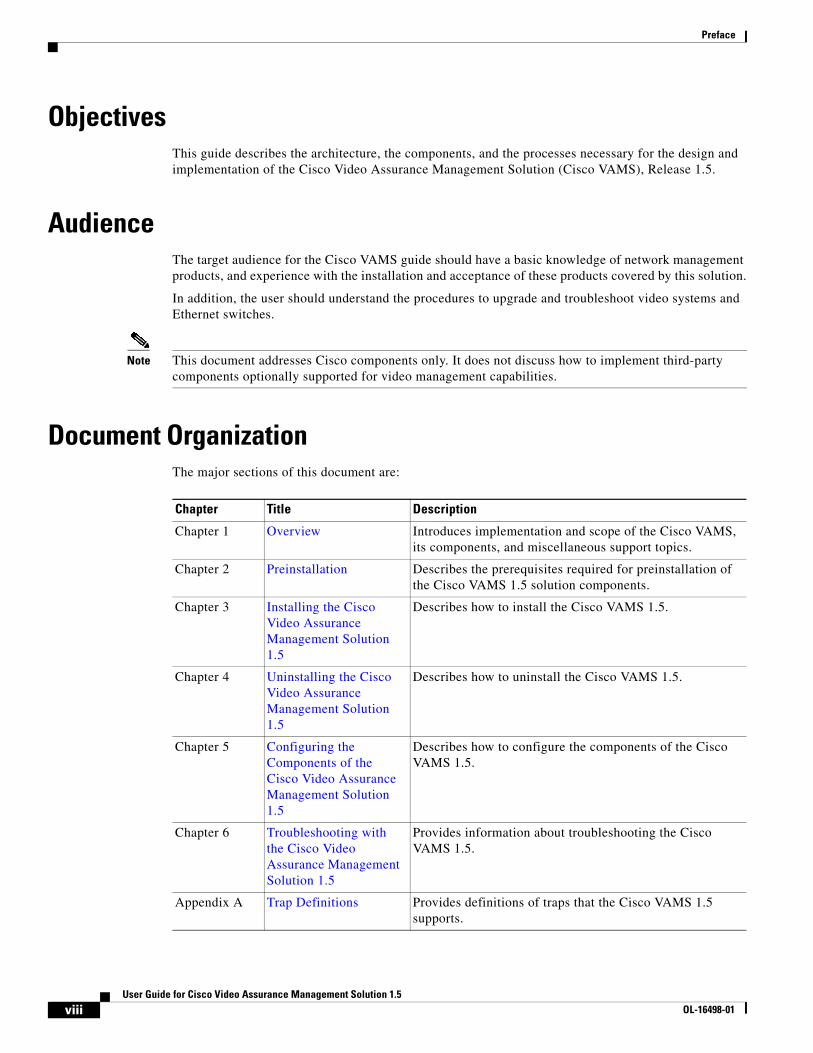
Document OrganizationThe major sections of this document are:
Chapter Title Description
Chapter 1 Overview Introduces implementation and scope of the Cisco VAMS, its components, and miscellaneous support topics.
Chapter 2 Preinstallation Describes the prerequisites required for preinstallation of the Cisco VAMS 1.5 solution components.
Chapter 3 Installing the Cisco Video Assurance Management Solution 1.5
Describes how to install the Cisco VAMS 1.5.
Chapter 4 Uninstalling the Cisco Video Assurance Management Solution 1.5
Describes how to uninstall the Cisco VAMS 1.5.
Chapter 5 Configuring the Components of the Cisco Video Assurance Management Solution 1.5
Describes how to configure the components of the Cisco VAMS 1.5.
Chapter 6 Troubleshooting with the Cisco Video Assurance Management Solution 1.5
Provides information about troubleshooting the Cisco VAMS 1.5.
Appendix A Trap Definitions Provides definitions of traps that the Cisco VAMS 1.5 supports.
viiiUser Guide for Cisco Video Assurance Management Solution 1.5
OL-16498-01
Preface
Related DocumentationFor information beyond the scope of this document, or for additional information about the Cisco VAMS product and its third-party documentation, refer to:
• Cisco Product Documentation, page ix
• Video Probe Documentation, page xiv
Cisco Product DocumentationCisco provides:
• Cisco Active Network Abstraction, page ix
• Cisco Multicast Manager, page xi
• Cisco Routers and Switches, page xii
• Cisco Info Center, page xiii
• Cisco Internet Protocol Television (IPTV) Solutions, page xiii
Cisco Active Network Abstraction
The Cisco Active Network Abstraction (ANA) 3.6 and Service Packs up through Service Pack 3 is the element management platform for the Cisco VAMS.
Cisco ANA Release Notes
• Release Notes for Cisco Active Network Abstraction, Version 3.6
• Release Notes for Cisco Active Network Abstraction, Version 3.6 Service Pack 1
• Release Notes for Cisco Active Network Abstraction, Version 3.6 Service Pack 2
• Release Notes for Cisco Active Network Abstraction, Version 3.6 Service Pack 3
Viewable online at:
http://www.cisco.com/en/US/products/ps6776/prod_release_notes_list.html
Cisco ANA User and Reference Guides
• Cisco Active Network Abstraction EventVision User Guide Version 3.6
• Cisco Active Network Abstraction EventVision User Guide Version 3.6 Service Pack 1
• Cisco Active Network Abstraction EventVision User Guide Version 3.6 Service Pack 2
• Cisco Active Network Abstraction EventVision User Guide Version 3.6 Service Pack 3
• Cisco Active Network Abstraction Fault Management User Guide Version 3.6
• Cisco Active Network Abstraction Fault Management User Guide Version 3.6 Service Pack 1
• Cisco Active Network Abstraction Fault Management User Guide Version 3.6 Service Pack 2
• Cisco Active Network Abstraction Fault Management User Guide Version 3.6 Service Pack 3
• Cisco Active Network Abstraction Managing MPLS User Guide Version 3.6
• Cisco Active Network Abstraction Managing MPLS User Guide Version 3.6 Service Pack 1
• Cisco Active Network Abstraction Managing MPLS User Guide 3.6 Service Pack 2
ixUser Guide for Cisco Video Assurance Management Solution 1.5
OL-16498-01
Preface
• Cisco Active Network Abstraction Managing MPLS User Guide 3.6 Service Pack 3
• Cisco Active Network Abstraction NetworkVision User Guide Version 3.6
• Cisco Active Network Abstraction NetworkVision User Guide 3.6 Service Pack 1
• Cisco Active Network Abstraction NetworkVision User Guide 3.6 Service Pack 2
• Cisco Active Network Abstraction NetworkVision User Guide 3.6 Service Pack 3
• Cisco Active Network Abstraction Technology Support and Information Model Reference Manual, Version 3.6
• Cisco Active Network Abstraction Technology Support and Information Model Reference Manual, 3.6 Service Pack 1
• Cisco Active Network Abstraction Technology Support and Information Reference Manual 3.6 Service Pack 2
• Cisco Active Network Abstraction Technology Support and Information Model Reference Manual, 3.6 Service Pack 3
• Cisco Active Network Abstraction 3.6 Virtual Network Element Reference Guide
• Cisco Active Network Abstraction Virtual Network Element Reference Guide, Version 3.6 Service Pack 1
• Cisco Active Network Abstraction VNE Reference Guide 3.6 Service Pack 2
Viewable online at:
http://www.cisco.com/en/US/products/ps6776/products_user_guide_list.html
Cisco ANA Configuration Guides
• Cisco Active Network Abstraction BQL User Guide 3.6
• Cisco Active Network Abstraction BQL User Guide 3.6 Service Pack 1
• Cisco Active Network Abstraction BQL User Guide 3.6 Service Pack 2
• Cisco Active Network Abstraction Command Builder User Guide 3.6
• Cisco Active Network Abstraction Command Builder User Guide 3.6 Service Pack 1
• Cisco Active Network Abstraction Command Builder User Guide 3.6 Service Pack 2
• Cisco Active Network Abstraction Customization User Guide 3.6
• Cisco Active Network Abstraction Customization User Guide 3.6 Service Pack 1
• Cisco Active Network Abstraction Customization User Guide 3.6 Service Pack 2
• Cisco Active Network Abstraction Customization User Guide 3.6 Service Pack 3
• Cisco Active Network Abstraction Workflow User Guide 3.6
• Cisco Active Network Abstraction Workflow User Guide Version 3.6 Service Pack 1
• Cisco Active Network Abstraction Workflow User Guide 3.6 Service Pack 2
Viewable online at:
http://www.cisco.com/en/US/products/ps6776/products_installation_and_configuration_guides_list. html
Cisco ANA Installation Guides
• Cisco Active Network Abstraction Installation Guide Version 3.6
• Cisco Active Network Abstraction Installation Guide 3.6 Service Pack 1
xUser Guide for Cisco Video Assurance Management Solution 1.5
OL-16498-01
Preface
• Cisco Active Network Abstraction Installation Guide 3.6 Service Pack 2
• Cisco Active Network Abstraction Installation Guide 3.6 Service Pack 3
Viewable online at:
http://cisco.com/en/US/products/ps6776/prod_installation_guides_list.html
Cisco ANA Administration Guides
• Cisco Active Network Abstraction Administrator Guide 3.6
• Cisco Active Network Abstraction Administrator Guide 3.6 Service Pack 1
• Cisco Active Network Abstraction Administrator Guide 3.6 Service Pack 2
• Cisco Active Network Abstraction Administrator Guide 3.6 Service Pack 3
• Cisco Active Network Abstraction Error Messages 3.6
• Cisco Active Network Abstraction Error Messages 3.6 Service Pack 1
• Cisco Active Network Abstraction Error Messages 3.6 Service Pack 2
• Cisco Active Network Abstraction Error Messages 3.6 Service Pack 3
• Cisco Active Network Abstraction High Availability User Guide 3.6
• Cisco Active Network Abstraction High Availability User Guide Version 3.6 Service Pack 1
• Cisco Active Network Abstraction High Availability User Guide 3.6 Service Pack 2
• Cisco Active Network Abstraction High Availability User Guide 3.6 Service Pack 3
• Cisco Active Network Abstraction Shell User Guide 3.6
• Cisco Active Network Abstraction Shell User Guide 3.6 Service Pack 1
• Cisco Active Network Abstraction Shell User Guide 3.6 Service Pack 2
• Cisco Active Network Abstraction Shell User Guide 3.6 Service Pack 3
Viewable online at:
http://www.cisco.com/en/US/products/ps6776/prod_maintenance_guides_list.html
Cisco Multicast Manager
Cisco Multicast Manager (CMM) 2.5.4 monitors the multicast control plane and forwards traps from the video transport network to Cisco ANA.
Cisco Multicast Manager Release Notes
Release Notes for Cisco Multicast Manager 2.5
Viewable online at:
http://www.cisco.com/en/US/products/ps6337/prod_release_notes_list.html
Cisco Multicast Manager Installation Guide
Installation Guide for Cisco Multicast Manager, 2.5
Viewable online at:
http://www.cisco.com/en/US/products/ps6337/prod_installation_guides_list.html
xiUser Guide for Cisco Video Assurance Management Solution 1.5
OL-16498-01
Preface
Cisco Multicast Manager User Guide
User Guide for Cisco Multicast Manager 2.5
Viewable online at:
http://www.cisco.com/en/US/products/ps6337/products_user_guide_list.html
Cisco Routers and Switches
The Cisco 7600 Series router, the Cisco Catalyst 6500 switch, the CRS-1, and a Catalyst 4948 Series switches form the core of the video transport network.
Cisco 7600 Series Routers
Viewable online at:
http://www.cisco.com/en/US/products/hw/routers/ps368/tsd_products_support_series_home.html
Release notes for the 12.2(33)SRB2, 12.2(33)SRB3, and 12.2(33)SRC1 IOS
Viewable online at:
http://www.cisco.com/en/US/docs/ios/12_2sr/release/notes/122SRrn.html
Cisco Catalyst 6500 Series Switches
Viewable online at:
http://www.cisco.com/en/US/products/hw/switches/ps708/tsd_products_support_series_home.html
Release notes for the 12.2(33)SRB2, 12.2(33)SRB3, and 12.2(33)SRC1 IOS
Viewable online at:
http://www.cisco.com/en/US/docs/ios/12_2sr/release/notes/122SRrn.html
Cisco Carrier Routing System (CRS-1)
Viewable online at:
http://www.cisco.com/en/US/products/ps5763/tsd_products_support_series_home.html
Release notes for the IOS-XR 3.6.1.12
Viewable online at:
http://www.cisco.com/en/US/docs/ios_xr_sw/iosxr_r3.6/general/release/notes/reln_361.html
Cisco Catalyst 4900 Series Switches
Viewable online at:
http://www.cisco.com/en/US/products/ps6021/tsd_products_support_series_home.html
Release notes for the 12.2(25)EWA6 and 12.2(31)SGA IOS
Viewable online at:
http://www.cisco.com/en/US/docs/switches/lan/catalyst4500/release/note/OL_9592.html
xiiUser Guide for Cisco Video Assurance Management Solution 1.5
OL-16498-01
Preface
Cisco Info Center
The Cisco VAMS 1.5 system architecture includes an interface between the IBM Netcool 7.1 product suite (under the Cisco Info Center or CIC product family) and Cisco ANA.
Documentation Guide and Supplemental License Agreement
• Cisco Info Center 7.1 Documentation Guide and Supplemental Licence Agreement
Viewable online at:
http://www.cisco.com/en/US/products/sw/netmgtsw/ps996/products_documentation_roadmap09186a0080805796.html
IBM Tivoli Netcool Product
See the following guides for this product, available on the IBM website.
User Guide
Netcool/OMNIbus 7.1 User Guide
Administration Guide
Netcool/OMNIbus 7.1 Administration Guide
Installation and Deployment
Netcool/OMNIbus 7.1 Installation and Deployment Guide
Release Notes
Netcool/OMNIbus 7.1 Release Notes
Probe and Gateway Guide
Netcool/OMNIbus 7.1 Probe and Gateway Guide
Cisco Internet Protocol Television (IPTV) Solutions
Video solutions that the Cisco VAMS 1.5 solution supports include:
Cisco IPTV Wireline Solutions
• Cisco Wireline Video/IPTV Solution Design and Implementation Guide, Release 1.1
Viewable online at:
http://www.cisco.com/en/US/products/ps6902/products_implementation_design_guide_book 09186a00806b5b4c.html
Cisco IPTV Cable Solutions
• Cisco Gigabit-Ethernet Optimized Video Networking Solution for Cable Design and Implementation Guide, Release 3.0
Viewable online at:
http://www.cisco.com/en/US/products/ps6902/products_implementation_design_guide_book 09186a00806470d8.html
xiiiUser Guide for Cisco Video Assurance Management Solution 1.5
OL-16498-01
Preface
Video Probe Documentation
Bridge Technologies
VB120 Broadcast IP-Probe User’s Manual v. 4.0
IneoQuest IQMediaMonitor Series M1 Singulus G1-T
• Hardware User’s Guide
• IQMediaAnalyzer Application User’s Guide
IneoQuest Cricket
See the IneoQuest website.
Mixed Signals Sentry
Mixed Signals Sentry Digital Content Monitor User Guide
PixelMetrix
DVStation-IP-3 User Manual, Software Version 4.17
Tektronix MTM400
• MTM400 MPEG Transport Stream Monitor User Manual
• MTM400 MPEG Transport Stream Monitor Technical Reference
• MTM400 MPEG Transport Stream Monitor Programmer Manual
Document ConventionsThis guide uses the following conventions to convey instructions and information.
Note Means reader take note. Notes contain helpful suggestions or references to material not covered in the publication.
Convention Description
boldface font Commands and keywords.
italic font Variables for which you supply values.
[ ] Keywords or arguments that appear within square brackets are optional.
{x | y | z} A choice of required keywords appears in braces separated by vertical bars. You must select one.
screen font Examples of information displayed on the screen.
boldface screen font
Examples of information you must enter.
< > Nonprinting characters, for example passwords, appear in angle brackets.
[ ] Default responses to system prompts appear in square brackets.
xivUser Guide for Cisco Video Assurance Management Solution 1.5
OL-16498-01
Preface
Timesaver Means the described action saves time. You can save time by performing the action described in the paragraph.
Tip Means the following information will help you solve a problem. The tips information might not be troubleshooting or even an action, but could be useful information, similar to a Timesaver.
Caution Means reader be careful. In this situation, you might do something that could result in equipment damage or loss of data.
Obtaining Documentation and Submitting a Service RequestFor information on obtaining documentation, submitting a service request, and gathering additional information, see the monthly What’s New in Cisco Product Documentation, which also lists all new and revised Cisco technical documentation, at:
http://www.cisco.com/en/US/docs/general/whatsnew/whatsnew.html
Subscribe to the What’s New in Cisco Product Documentation as a Really Simple Syndication (RSS) feed and set content to be delivered directly to your desktop by using a reader application. The RSS feeds are a free service and Cisco currently supports RSS version 2.0.
xvUser Guide for Cisco Video Assurance Management Solution 1.5
OL-16498-01

Preface
xviUser Guide for Cisco Video Assurance Management Solution 1.5
OL-16498-01
User Guide foOL-16498-01
C H A P T E R 1
OverviewThe User Guide for Cisco Video Assurance Management Solution 1.5 provides a complete overview of the hardware and software products that the Cisco Video Assurance Management Solution (Cisco VAMS) comprises. This guide describes key benefits and advantages, features, and technical specifications for the products that make up the Cisco VAMS 1.5. The guide also describes installation, configuration, and troubleshooting tasks.
You can use the Cisco VAMS 1.5 to diagnose and facilitate the tasks of monitoring the transport section of a multicast video network to:
• Monitor the health and performance of the network.
• Analyze and troubleshoot faults and exceptions.
• Ensure security, accountability and compliance with organizational policies and regulatory requirements.
This chapter contains:
• License Information, page 1-1
• Introduction to Cisco VAMS 1.5, page 1-2
• Cisco VAMS Solution Components, page 1-6
• Cisco Advanced Services Support for VAMS, page 1-28
License InformationSee Appendix B, “End User License Agreement Supplement.”
1-1r Cisco Video Assurance Management Solution 1.5
Chapter 1 Overview Introduction to Cisco VAMS 1.5
Introduction to Cisco VAMS 1.5Cisco VAMS 1.5 delivers to service providers real-time, centralized monitoring of backbone, regional, and aggregation networks for broadcast video transport. Cisco VAMS 1.5 provides the framework for a flexible end-to-end assurance platform for video. See the “Solution Component Versions” section on page 1-7 for descriptions of the solution components and required software versions.
Cisco VAMS 1.5 provides a modular architecture for monitoring video networks: VAMS 1.5 uses:
• Cisco Multicast Manager (CMM 2.5) with Patch 2.5.4 for multicast monitoring and troubleshooting functions
• The Cisco Info Center (CIC) product suite1 to monitor events from CMM.
Cisco has bundled the CIC/Netcool the ObjectServer (central database) and Webtop (web GUI for event list viewing) from the CIC product suite with the VAM solution.
The CIC product suite includes two additional product components from the IBM Tivoli product suite:
– IBM Tivoli Business and Services Manager (TBSM), a service dashboard and visualization tool.
– IBM Tivoli Impact, which supports the definition of service and network correlations.
This combination of CIC and Netcool functionality accomplishes two key objectives for Cisco VAMS 1.5. It provides:
– Connectivity between CMM and CIC.
– A “Single Pane of Glass” toolset2 for Cisco VAMS 1.5.
CIC includes rules files that define multicast alerts from various sources like probes and routers. The rules file includes code that extracts the multicast group and source information from these alerts and provides the operator with a CMM Multicast Trace option.
By integrating CMM with CIC you can now view all the alarm conditions and data for service level correlation and analysis. Additionally, you can launch troubleshooting and diagnostic analysis from one system instead of looking at several systems.
• Cisco ANA 3.6 Service Pack 3 to build an abstracted network model through a set of virtual network elements (VNEs).
Each VNE represents an element in the managed network. Cisco VAMS 1.5 extends the base functions of the Cisco ANA 3.6.2 VNEs for Cisco 7600 Series routers, Cisco Carrier Routing System (CRS-1) devices, and Cisco Catalyst 4948 and 6500 Series switches. These VNE extensions address the specific requirements of video delivery across the IP network.
Finally, Cisco VAMS 1.5 includes generic VNEs that support specific video probes; this release includes VNEs for IneoQuest, Mixed Signals, and Tektronix video probes.
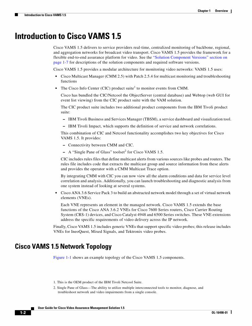
Cisco VAMS 1.5 Network TopologyFigure 1-1 shows an example topology of the Cisco VAMS 1.5 components.
1. This is the OEM product of the IBM Tivoli Netcool Suite.
2. Single Pane of Glass—The ability to utilize multiple interconnected tools to monitor, diagnose, and troubleshoot network and video impairments from a single console.
1-2User Guide for Cisco Video Assurance Management Solution 1.5
OL-16498-01
Chapter 1 Overview Introduction to Cisco VAMS 1.5
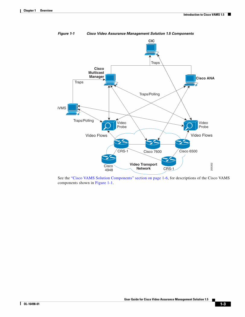
Figure 1-1 Cisco Video Assurance Management Solution 1.5 Components
See the “Cisco VAMS Solution Components” section on page 1-6, for descriptions of the Cisco VAMS components shown in Figure 1-1.
Multicast Cisco
Manager
Video T ranspor t Netw ork
Cisco 494 8
CRS-1 Cisco 7600
Video Probe
CRS-1
Cisco ANA
Tr aps/P ollin g
iVMS
Tr ap s
CI C
Tr ap s
Video Probe
Video Fl ow s Video Fl ow s
Tr aps/P ollin g
2053
52
Cisco 6500
1-3User Guide for Cisco Video Assurance Management Solution 1.5
OL-16498-01
Chapter 1 Overview Introduction to Cisco VAMS 1.5
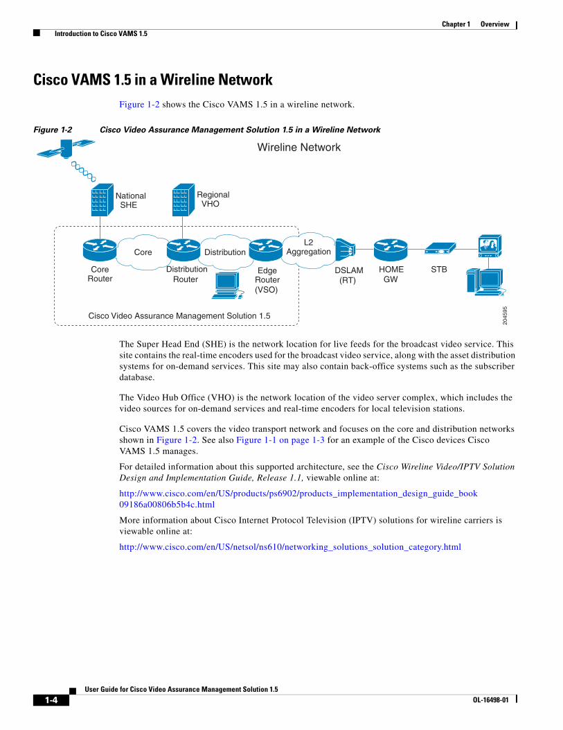
Cisco VAMS 1.5 in a Wireline NetworkFigure 1-2 shows the Cisco VAMS 1.5 in a wireline network.
Figure 1-2 Cisco Video Assurance Management Solution 1.5 in a Wireline Network
The Super Head End (SHE) is the network location for live feeds for the broadcast video service. This site contains the real-time encoders used for the broadcast video service, along with the asset distribution systems for on-demand services. This site may also contain back-office systems such as the subscriber database.
The Video Hub Office (VHO) is the network location of the video server complex, which includes the video sources for on-demand services and real-time encoders for local television stations.
Cisco VAMS 1.5 covers the video transport network and focuses on the core and distribution networks shown in Figure 1-2. See also Figure 1-1 on page 1-3 for an example of the Cisco devices Cisco VAMS 1.5 manages.
For detailed information about this supported architecture, see the Cisco Wireline Video/IPTV Solution Design and Implementation Guide, Release 1.1, viewable online at:
http://www.cisco.com/en/US/products/ps6902/products_implementation_design_guide_book 09186a00806b5b4c.html
More information about Cisco Internet Protocol Television (IPTV) solutions for wireline carriers is viewable online at:
http://www.cisco.com/en/US/netsol/ns610/networking_solutions_solution_category.html
Cisco Video Assurance Management Solution 1.5
Core Distr ib ution L2
Aggregation
Core Router
Edge Router (VSO)
Regional VHO
National SHE
DSLAM (RT)
HOME GW
Wireline Network
STB Router Distribution
2045
95
1-4User Guide for Cisco Video Assurance Management Solution 1.5
OL-16498-01
Chapter 1 Overview Introduction to Cisco VAMS 1.5
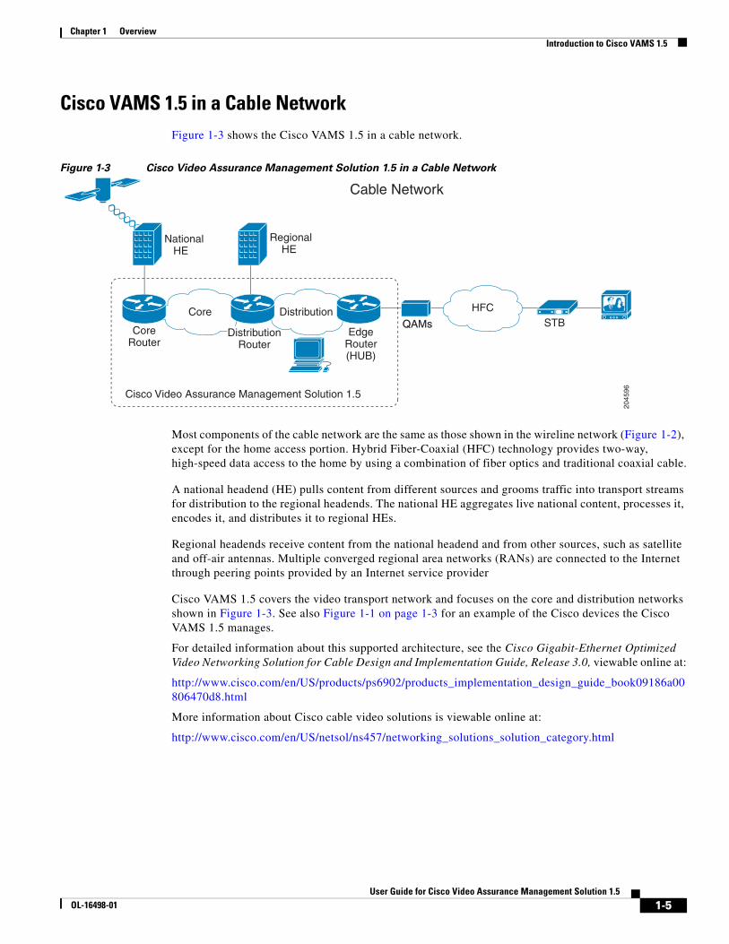
Cisco VAMS 1.5 in a Cable NetworkFigure 1-3 shows the Cisco VAMS 1.5 in a cable network.
Figure 1-3 Cisco Video Assurance Management Solution 1.5 in a Cable Network
Most components of the cable network are the same as those shown in the wireline network (Figure 1-2), except for the home access portion. Hybrid Fiber-Coaxial (HFC) technology provides two-way, high-speed data access to the home by using a combination of fiber optics and traditional coaxial cable.
A national headend (HE) pulls content from different sources and grooms traffic into transport streams for distribution to the regional headends. The national HE aggregates live national content, processes it, encodes it, and distributes it to regional HEs.
Regional headends receive content from the national headend and from other sources, such as satellite and off-air antennas. Multiple converged regional area networks (RANs) are connected to the Internet through peering points provided by an Internet service provider
Cisco VAMS 1.5 covers the video transport network and focuses on the core and distribution networks shown in Figure 1-3. See also Figure 1-1 on page 1-3 for an example of the Cisco devices the Cisco VAMS 1.5 manages.
For detailed information about this supported architecture, see the Cisco Gigabit-Ethernet Optimized Video Networking Solution for Cable Design and Implementation Guide, Release 3.0, viewable online at:
http://www.cisco.com/en/US/products/ps6902/products_implementation_design_guide_book09186a00806470d8.html
More information about Cisco cable video solutions is viewable online at:
http://www.cisco.com/en/US/netsol/ns457/networking_solutions_solution_category.html
Cisco Video Assurance Management Solution 1.5
Cable Network
Core Distribution HFC
Core Router
Distribution Router
Edge Router (HUB)
Regional HE
National HE
QAMsQAMs STB
2045
96
1-5User Guide for Cisco Video Assurance Management Solution 1.5
OL-16498-01
Chapter 1 Overview Cisco VAMS Solution Components
Cisco VAMS Solution ComponentsThe Cisco VAMS 1.5 solution comprises:
• Cisco Multicast Manager 2.5.4, page 1-8
• Cisco Info Center, page 1-12
• Cisco ANA 3.6.3, page 1-17
• Third-Party Video Probes, page 1-26
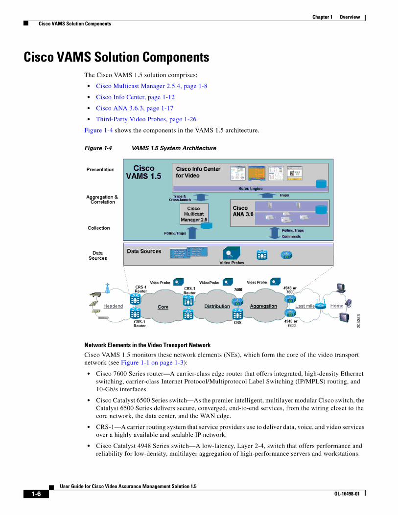
Figure 1-4 shows the components in the VAMS 1.5 architecture.
Figure 1-4 VAMS 1.5 System Architecture
Network Elements in the Video Transport Network
Cisco VAMS 1.5 monitors these network elements (NEs), which form the core of the video transport network (see Figure 1-1 on page 1-3):
• Cisco 7600 Series router—A carrier-class edge router that offers integrated, high-density Ethernet switching, carrier-class Internet Protocol/Multiprotocol Label Switching (IP/MPLS) routing, and 10-Gb/s interfaces.
• Cisco Catalyst 6500 Series switch—As the premier intelligent, multilayer modular Cisco switch, the Catalyst 6500 Series delivers secure, converged, end-to-end services, from the wiring closet to the core network, the data center, and the WAN edge.
• CRS-1—A carrier routing system that service providers use to deliver data, voice, and video services over a highly available and scalable IP network.
• Cisco Catalyst 4948 Series switch—A low-latency, Layer 2-4, switch that offers performance and reliability for low-density, multilayer aggregation of high-performance servers and workstations.
1-6User Guide for Cisco Video Assurance Management Solution 1.5
OL-16498-01
Chapter 1 Overview Cisco VAMS Solution Components
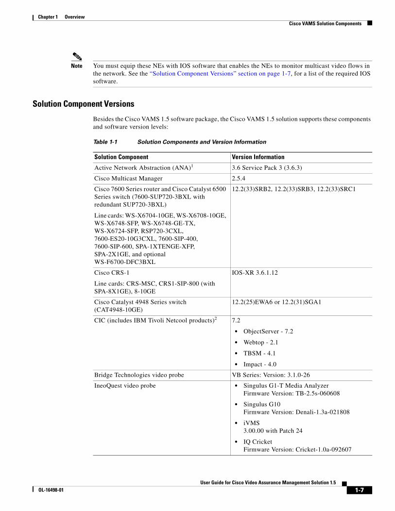
Note You must equip these NEs with IOS software that enables the NEs to monitor multicast video flows in the network. See the “Solution Component Versions” section on page 1-7, for a list of the required IOS software.
Solution Component Versions
Besides the Cisco VAMS 1.5 software package, the Cisco VAMS 1.5 solution supports these components and software version levels:
Table 1-1 Solution Components and Version Information
Solution Component Version Information
Active Network Abstraction (ANA)1 3.6 Service Pack 3 (3.6.3)
Cisco Multicast Manager 2.5.4
Cisco 7600 Series router and Cisco Catalyst 6500 Series switch (7600-SUP720-3BXL with redundant SUP720-3BXL)
Line cards: WS-X6704-10GE, WS-X6708-10GE, WS-X6748-SFP, WS-X6748-GE-TX, WS-X6724-SFP, RSP720-3CXL, 7600-ES20-10G3CXL, 7600-SIP-400, 7600-SIP-600, SPA-1XTENGE-XFP, SPA-2X1GE, and optional WS-F6700-DFC3BXL
12.2(33)SRB2, 12.2(33)SRB3, 12.2(33)SRC1
Cisco CRS-1
Line cards: CRS-MSC, CRS1-SIP-800 (with SPA-8X1GE), 8-10GE
IOS-XR 3.6.1.12
Cisco Catalyst 4948 Series switch (CAT4948-10GE)
12.2(25)EWA6 or 12.2(31)SGA1
CIC (includes IBM Tivoli Netcool products)2 7.2
• ObjectServer - 7.2
• Webtop - 2.1
• TBSM - 4.1
• Impact - 4.0
Bridge Technologies video probe VB Series: Version: 3.1.0-26
IneoQuest video probe • Singulus G1-T Media Analyzer Firmware Version: TB-2.5s-060608
• Singulus G10 Firmware Version: Denali-1.3a-021808
• iVMS 3.00.00 with Patch 24
• IQ Cricket Firmware Version: Cricket-1.0a-092607
1-7User Guide for Cisco Video Assurance Management Solution 1.5
OL-16498-01
Chapter 1 Overview Cisco VAMS Solution Components
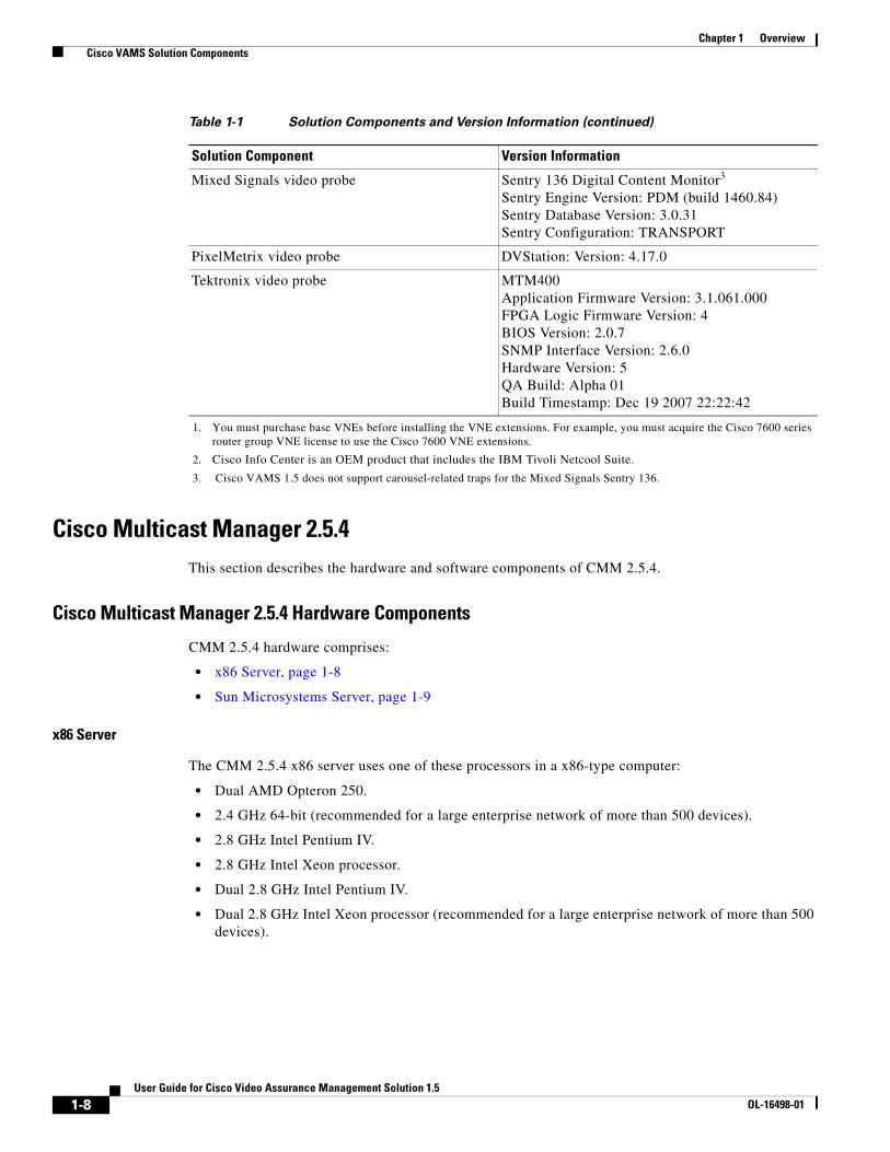
Cisco Multicast Manager 2.5.4This section describes the hardware and software components of CMM 2.5.4.
Cisco Multicast Manager 2.5.4 Hardware Components
CMM 2.5.4 hardware comprises:
• x86 Server, page 1-8
• Sun Microsystems Server, page 1-9
x86 Server
The CMM 2.5.4 x86 server uses one of these processors in a x86-type computer:
• Dual AMD Opteron 250.
• 2.4 GHz 64-bit (recommended for a large enterprise network of more than 500 devices).
• 2.8 GHz Intel Pentium IV.
• 2.8 GHz Intel Xeon processor.
• Dual 2.8 GHz Intel Pentium IV.
• Dual 2.8 GHz Intel Xeon processor (recommended for a large enterprise network of more than 500 devices).
Mixed Signals video probe Sentry 136 Digital Content Monitor3 Sentry Engine Version: PDM (build 1460.84) Sentry Database Version: 3.0.31 Sentry Configuration: TRANSPORT
PixelMetrix video probe DVStation: Version: 4.17.0
Tektronix video probe MTM400 Application Firmware Version: 3.1.061.000 FPGA Logic Firmware Version: 4 BIOS Version: 2.0.7 SNMP Interface Version: 2.6.0 Hardware Version: 5 QA Build: Alpha 01 Build Timestamp: Dec 19 2007 22:22:42
1. You must purchase base VNEs before installing the VNE extensions. For example, you must acquire the Cisco 7600 series router group VNE license to use the Cisco 7600 VNE extensions.
2. Cisco Info Center is an OEM product that includes the IBM Tivoli Netcool Suite.
3. Cisco VAMS 1.5 does not support carousel-related traps for the Mixed Signals Sentry 136.
Table 1-1 Solution Components and Version Information (continued)
Solution Component Version Information
1-8User Guide for Cisco Video Assurance Management Solution 1.5
OL-16498-01
Chapter 1 Overview Cisco VAMS Solution Components
Sun Microsystems Server
The CMM 2.5.4 Sun Microsystems server uses one of these Sun Fire series workstations:
• Sun Fire V440 (up to four 1.593 GHz UltraSPARC IIIi processors for a large enterprise network of more than 500 devices),
• Sun Fire V240 (one 1.34 GHz or two 1.5 GHz UltraSPARC processors).
CMM 2.5.4 Application
Using an x86-type computer running Linux or a Sun Microsystems Sun Fire series workstation running Solaris, the CMM 2.5.4 application (a web-based multicast troubleshooting tool) has two components: Administration and Multicast Manager. CMM 2.5.4 uses SNMP MIB polling to monitor devices and traffic in the network. CMM 2.5.4 also provides metrics and alerts, which it then forwards to the ANA as SNMP traps. Based on the unique requirements of the network environment, the SNMP traps are user-configurable.
The CMM 2.5.4 can monitor multicast-specific data such as:
• Rendezvous points (RP)
• Designated routers (DR)
• Multicast traffic (Layer 2 and Layer 3)
• Multicast bandwidth (Layer 2 and Layer 3)
• Layer 3 multicast trees
• Tree Change events
• PPS/BPS per flow monitoring
The CMM 2.5.4 also provides detailed diagnostics and a health-check capability.
You use CMM 2.5.4 to set thresholds, generate notifications, and forward them to CIC.
See the User Guide for Cisco Multicast Manager 2.5, viewable online at:
http://www.cisco.com/en/US/docs/net_mgmt/cisco_multicast_manager/2.5/user/guide/CMM_25_User_Guide.html
1-9User Guide for Cisco Video Assurance Management Solution 1.5
OL-16498-01
Chapter 1 Overview Cisco VAMS Solution Components
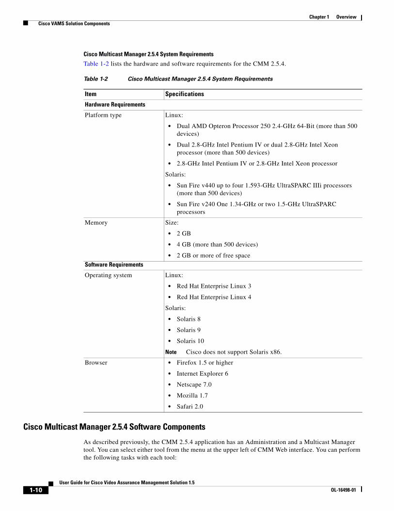
Cisco Multicast Manager 2.5.4 System Requirements
Table 1-2 lists the hardware and software requirements for the CMM 2.5.4.
Cisco Multicast Manager 2.5.4 Software Components
As described previously, the CMM 2.5.4 application has an Administration and a Multicast Manager tool. You can select either tool from the menu at the upper left of CMM Web interface. You can perform the following tasks with each tool:
Table 1-2 Cisco Multicast Manager 2.5.4 System Requirements
Item Specifications
Hardware Requirements
Platform type Linux:
• Dual AMD Opteron Processor 250 2.4-GHz 64-Bit (more than 500 devices)
• Dual 2.8-GHz Intel Pentium IV or dual 2.8-GHz Intel Xeon processor (more than 500 devices)
• 2.8-GHz Intel Pentium IV or 2.8-GHz Intel Xeon processor
Solaris:
• Sun Fire v440 up to four 1.593-GHz UltraSPARC IIIi processors (more than 500 devices)
• Sun Fire v240 One 1.34-GHz or two 1.5-GHz UltraSPARC processors
Memory Size:
• 2 GB
• 4 GB (more than 500 devices)
• 2 GB or more of free space
Software Requirements
Operating system Linux:
• Red Hat Enterprise Linux 3
• Red Hat Enterprise Linux 4
Solaris:
• Solaris 8
• Solaris 9
• Solaris 10
Note Cisco does not support Solaris x86.
Browser • Firefox 1.5 or higher
• Internet Explorer 6
• Netscape 7.0
• Mozilla 1.7
• Safari 2.0
1-10User Guide for Cisco Video Assurance Management Solution 1.5
OL-16498-01
Chapter 1 Overview Cisco VAMS Solution Components
Administration
• Manage domains
• Use administrative utilities
• Configure security
• Manage users
• Perform discovery
• Configure devices
• Configure global polling
• Configure multicast polling
• Manage addresses
Multicast Manager
• View events through the Home page.
• View topology through the Topology page, such as:
– Each router and its local interfaces.
– The interfaces on each of the router's PIM neighbors.
– The names of the routers and their PIM neighbors.
• Manage report through the Reporting page, such as:
– A record of the latest SNMP traps sent.
– Historical graphs or trends.
– Routers in the database IOS versions.
– Video probe reports.
– Reports on VPN routing/forwarding instances (VRFs).
• Manage a global view and a router-specific view of your network through the Diagnostics page, such as:
– Showing active sources and groups in the network.
– Finding sources and receivers in the network.
– Viewing the status of all devices in the current multicast domain.
– Viewing all the routers in the database.
– Viewing all the RPs that CMM is aware of, based on discovery.
– Seeing the interfaces that have joined onto a particular group.
– Viewing all the routers running Multicast Source Discovery Protocol (MSDP) and their peering connectivity. You can also view details for a specific router, such as peering information and the SA cache.
– Viewing Layer 2 Multicast Information and Layer 2 Host IPs.
– Running preconfigured network tests using the Health Check facility.
– Enable the CMM to gather accurate packet forwarding statistics and other information in a timely manner.
– Viewing the top 20 talkers, sorted by long term.
1-11User Guide for Cisco Video Assurance Management Solution 1.5
OL-16498-01
Chapter 1 Overview Cisco VAMS Solution Components
– Viewing diagnostic information about video probes and the flows that they are monitoring.
– Viewing a detailed trace about a video flow and a topology tree that shows: RPs, routers, interfaces, and probes.
– Viewing detailed information about the status of Multicast VPNs, including: VRF table configurations, Provider Edge (PE) device configurations, and the current status of a specified VRF.
– Viewing specific multicast diagnostics on a router.
• Viewing a PDF version of the User Guide for the Cisco Multicast Manager 2.5 through the Help page.
For complete hardware and software requirements, see the following books:
Installation Guide for the Cisco Multicast Manager 2.5, viewable online at: http://www.cisco.com/en/US/docs/net_mgmt/cisco_multicast_manager/2.5/installation/guide/ CMM_25_install_guide.html
User Guide for the Cisco Multicast Manager 2.5, viewable online at:
http://www.cisco.com/en/US/docs/net_mgmt/cisco_multicast_manager/2.5/user/guide/CMM_25_User_Guide.html
Cisco Info CenterCIC/Netcool delivers real-time centralized monitoring and root-cause analysis by integrating the IBM Tivoli Netcool 7.1 components and the CIC with Cisco ANA 3.6.3, CMM 2.5.4, and video probe devices.
CIC alone provides real-time monitoring, management, and event deduplication3 or pruning, and helps enterprises and service providers proactively manage their IT infrastructures to ensure the continuous uptime of business services and applications.
The CIC/Netcool components comprise:
• IBM Tivoli Netcool/OMNIbus and ObjectServer, page 1-12
• IBM Tivoli Netcool/Webtop, page 1-14
• IBM Tivoli Netcool/Impact, page 1-15
• IBM Tivoli Business Service Manager, page 1-15
• IBM Tivoli Netcool GUI Foundation, page 1-16
• IBM Tivoli Netcool Probes, page 1-16
• Rules Files, page 1-16
IBM Tivoli Netcool/OMNIbus and ObjectServer
The IBM Tivoli Netcool/OMNIbus service level management (SLM) system collects enterprise-wide event information from several different network data sources, and presents a simplified view of this information to operators and administrators.
This information:
• Assigns information to operators.
• Travels to help desk systems.
3. For a detailed definition, see the Glossary.
1-12User Guide for Cisco Video Assurance Management Solution 1.5
OL-16498-01
Chapter 1 Overview Cisco VAMS Solution Components
• Logs in a database.
• Replicates on a remote Netcool/OMNIbus system.
• Triggers automatic responses to certain alerts.
Netcool/OMNIbus can also consolidate information from different domain-limited network management platforms in remote locations. By working in conjunction with existing management systems and applications, Netcool/OMNIbus minimizes deployment time; thus, you can use their network management skills.
Netcool/OMNIbus tracks alert information in a high-performance, in-memory database, and presents information of interest to you through individually configurable filters and views.
Netcool/OMNIbus automation functions can perform intelligent processing on managed alerts.
The ObjectServer is the in-memory database server at the core of Netcool/OMNIbus. The ObjectServer forwards alert information from external programs, such as probes, monitors, and gateways, stored and managed in database tables, and visible in the event list.
See the following books:
• Netcool/OMNIbus v7 User Guide is viewable online at:
http://www.cisco.com/en/US/products/sw/netmgtsw/ps996/products_user_guide_book09186a008047d044.html
• Netcool/OMNIbus v7 ObjectServer Gateway Guide is viewable online at:
http://www.cisco.com/en/US/products/sw/netmgtsw/ps996/products_technical_reference_book09186a008047d049.html
IIBM Tivoli Netcool/OMNIbus and ObjectServer Requirements
On Sun Microsystems SPARC-based platforms, Cisco supports:
• Solaris 8
• Solaris 9
• Solaris 10
On Hewlett-Packard PA-RISC-based platforms, Cisco supports:
HP-UX 11i (11.11)
On IBM PowerPC-based platforms:
• AIX 5L (5.2 RS/6000 32-bit)
• AIX 5L (5.3 RS/6000 32-bit)
On Intel x86 processor and chipset-based platforms, Cisco supports:
• Microsoft Windows 2000 Server
• Microsoft Windows 2000 Advanced Server
• Microsoft Windows 2003 Server
• Microsoft Windows 2000 Professional—desktop component only
• Microsoft Windows XP—desktop component only
• Red Hat Enterprise Linux AS, ES, and WS 3
• Red Hat Enterprise Linux AS, ES, and WS 4
• SUSE Linux Enterprise Server 9.2
1-13User Guide for Cisco Video Assurance Management Solution 1.5
OL-16498-01
Chapter 1 Overview Cisco VAMS Solution Components
JRE Requirements
The Netcool/OMNIbus Administrator GUI and the nco_confpack utility require the JRE to be installed on your system.
Netcool/OMNIbus supports the following JREs:
• Javasoft JRE 1.5 on Linux, Solaris, and Windows platforms
• IBM JRE 1.4.2 on AIX platforms
• HP JRE 1.5 on HP-UX platforms
User Interface Requirements
Netcool/OMNIbus supports the following user interface environments:
• UNIX/Motif 1.2 or CDE
• Microsoft Windows 2000, 2003, and XP
IBM Tivoli Netcool/Webtop
IBM Tivoli Netcool/Webtop publishes alerts for viewing in a web browser. Users can manipulate them by using an active event list launched from a web browser. The Webtop includes server administration pages to set up users, table views, and other configurable elements.
Webtop includes the Webtop Editor; a tool for creating and editing maps (filters and views). Webtop publishes Netcool alerts and active event list applets over HTTP or HTTPS4 (HTTP with SSL) protocol to supported web browsers. Launched from a web browser, the active event list offers the functionality of Netcool/Java EventList (JEL) to acknowledge, prioritize, and delete alerts by using the Webtop technology.
Using a client-server architecture, the Webtop server runs inside the IBM Tivoli Netcool GUI Foundation application (see the “IBM Tivoli Netcool GUI Foundation” section on page 1-16 for more information). Clients connect to the IBM Tivoli Netcool GUI Foundation to access Netcool/Webtop.
See the administration guide for this product, available on the IBM website.
You can also launch Netcool/Webtop from the Tivoli Business Service Manager (TBSM) application. For information on launching TBSM and Netcool/Webtop to view VAMS 1.5 alerts, see Monitoring ANA, CMM, and Video Probe Events with TBSM, page 6-1.
IBM Tivoli Netcool/Webtop Requirements
On Sun Microsystems SPARC-based platforms, Cisco supports:
• Solaris 9
• Solaris 10
On Hewlett-Packard PA-RISC-based platforms, Cisco supports:
HP-UX 11i (11.11)
On IBM PowerPC-based platforms:
AIX 5L (5.3 RS/6000 32-bit)
On Intel x86 processor and chipset-based platforms, Cisco supports:
• Microsoft Windows 2003 Server (32 and 64 bit)
4. HTTPS—HTTP with SSL (secure sockets layer) encryption for security.
1-14User Guide for Cisco Video Assurance Management Solution 1.5
OL-16498-01
Chapter 1 Overview Cisco VAMS Solution Components
• Microsoft Windows XP SP2
• Red Hat Enterprise Linux AS, ES, and WS 3
• Red Hat Enterprise Linux AS, ES, and WS 4
• SUSE Linux Enterprise Server 9
• SUSE Linux Enterprise Server 10
Note Ensure that the IBM Tivoli Netcool Security Manager is installed, running, and accessible; and that you know the host, port, and administrative user name and password for the IBM Tivoli Netcool Security Manager before you install IBM Tivoli Netcool/Webtop. For information about how to install and configure the IBM Tivoli Netcool Security Manager, see the security manager installation guide for this product, available on the IBM website.
IBM Tivoli Netcool/Impact
IBM Tivoli Netcool/Impact is the analysis and correlation engine for the Netcool suite of network management products. IBM Tivoli Netcool/Impact allows you to extensively customize and enhance Netcool/OMNIbus and other Netcool products by adding such functionality as advanced event and business data correlation, event enrichment and event notification. In addition, you can use IBM Tivoli Netcool/Impact to integrate IBM Tivoli Netcool/OMNIbus with a wide variety of third-party software, including databases, messaging systems and network inventory applications.
See the administration, user interface, and solutions guides for this product, available on the IBM website.
IBM Tivoli Business Service Manager
IBM Tivoli Business Service Manager (TBSM) delivers technology to visualize and assure the health and performance of critical business services.
TBSM functions:
• Build business service models.
• Integrate business service status from data sources or event sources including the Netcool/OMNIbus ObjectServer.
• Monitor service outages based on service level agreements.
• Build customized business service views, scorecards, and dashboards.
• Tailor views to different users and roles including service manager, operator, or executive.
• Provide dynamic visualization of key performance indicators (KPIs) and other critical business metrics.
• Provide self-management through monitoring of key components by using IBM Tivoli Monitoring (ITM).
The TBSM tools enable a service model that integrates with the Netcool/OMNIbus ObjectServer alerts, or optionally with the data from a structured query language (SQL) data source. TBSM processes the external data based on the service model data you create in the TBSM database and returns a new or updated TBSM service event to the Netcool/OMNIbus ObjectServer.
1-15User Guide for Cisco Video Assurance Management Solution 1.5
OL-16498-01
Chapter 1 Overview Cisco VAMS Solution Components
TBSM provides a console that allows you to logically link services and business requirements in the service model. The service model provides you with a view on the performance of your business services, second by second.
See the installation, quick start, administrator, service configuration, customizing, and troubleshooting guides for this product, available on the IBM website.
JRE Requirements
Netcool/TBSM version 4.1.1 requires the Java Runtime Environment (JRE) to be installed on your system.
Netcool/TBSM supports the following JREs:
• Javasoft JRE 1.5 on Linux, Solaris, and Windows platforms
• IBM JRE 1.4.2 on AIX platforms
• HP JRE 1.5 on HP-UX platforms
Note JRE versions higher than 1.5 in client web browsers result in a failure of the Service Viewer and the Service Details within the TBSM window.
IBM Tivoli Netcool GUI Foundation
The IBM Tivoli Netcool GUI Foundation (NGF) is a server application that delivers web-based Netcool products in a single, unified framework. The IBM Tivoli Netcool GUI Foundation provides single sign-on, consolidated user management, and a single point of access for different IBM Tivoli Netcool applications. The IBM Tivoli Netcool GUI Foundation also provides the ability to create customized pages and administer access to content by user, role, or group.
The IBM Tivoli Netcool GUI Foundation is installed automatically with the first IBM Tivoli Netcool GUI Foundation-enabled product. Subsequent products may install updated versions of the IBM Tivoli Netcool GUI Foundation. The Netcool GUI Foundation is not available separately.
The IBM Tivoli Netcool GUI Foundation uses IBM Tivoli Netcool/Security Manager for authentication and authorization.
See the administration guide for this product, available on the IBM website.
IBM Tivoli Netcool Probes
The IBM Tivoli Netcool Probes connect to an event source, detect and acquire event data, and forward the data to the ObjectServer as alerts. Probes use the logic specified in a rules file to manipulate the event elements before converting them into fields of an alert in the ObjectServer alerts.status table.
Uniquely designed, each probe can acquire event data from a specific source. Probes can also acquire data from any stable data source, including devices, databases, and log files.
Rules Files
Included in CIC/Netcool, the rules files enable streamlined communication between the CMM and Cisco ANA components and the Netcool ObjectServer. This functionality includes the decoding of CMM and Cisco ANA trap information pushed up from CMM or Cisco ANA into the ObjectServer database on the Netcool server.
1-16User Guide for Cisco Video Assurance Management Solution 1.5
OL-16498-01
Chapter 1 Overview Cisco VAMS Solution Components
Cisco ANA 3.6.3 This section describes the hardware and software components of Cisco ANA 3.6.3.
Cisco ANA 3.6.3 Hardware Components
Cisco ANA 3.6.3 hardware comprises:
• Cisco ANA Servers, page 1-17
• Cisco ANA Clients, page 1-20
Note The hardware recommendations assume that the Cisco ANA 3.6.3 software will not share the hardware with additional applications.
Cisco ANA Servers
Cisco ANA uses two server types, each performing different activities:
• Cisco ANA Gateway, page 1-17
• Cisco ANA Unit, page 1-18
Cisco ANA Gateway
The Cisco ANA Gateway uses a Sun Fire V490 running Solaris OS 10. It is the gateway through which all clients, including any operations support systems or business support systems (OSS/BSS) applications as well as the Cisco ANA clients, can access the system. The gateway is an extended Cisco ANA unit (see the “Cisco ANA Unit” section on page 1-18). It enforces access control and security for all connections, and manages client sessions. In addition, it functions as a repository for storing configuration, network and system events, and alarms.
Another important function of the gateway is to map network resources to the business context. As a result, Cisco ANA can contain information not directly in the network (such as virtual private networks [VPNs] and subscribers) and display it to northbound applications.
Cisco ANA Gateway Requirements
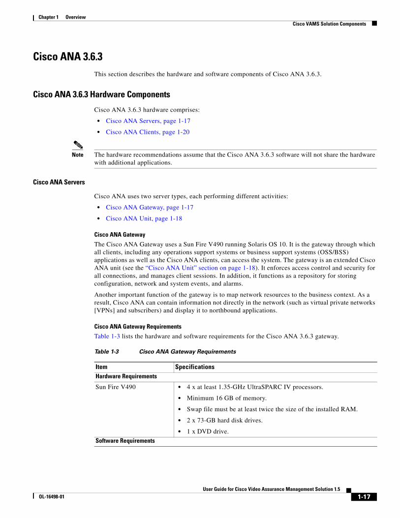
Table 1-3 lists the hardware and software requirements for the Cisco ANA 3.6.3 gateway.
Table 1-3 Cisco ANA Gateway Requirements
Item SpecificationsHardware Requirements
Sun Fire V490 • 4 x at least 1.35-GHz UltraSPARC IV processors.
• Minimum 16 GB of memory.
• Swap file must be at least twice the size of the installed RAM.
• 2 x 73-GB hard disk drives.
• 1 x DVD drive.
Software Requirements
1-17User Guide for Cisco Video Assurance Management Solution 1.5
OL-16498-01
Chapter 1 Overview Cisco VAMS Solution Components
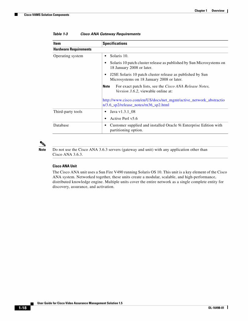
Note Do not use the Cisco ANA 3.6.3 servers (gateway and unit) with any application other than Cisco ANA 3.6.3.
Cisco ANA Unit
The Cisco ANA unit uses a Sun Fire V490 running Solaris OS 10. This unit is a key element of the Cisco ANA system. Networked together, these units create a modular, scalable, and high-performance, distributed knowledge engine. Multiple units cover the entire network as a single complete entity for discovery, assurance, and activation.
Operating system • Solaris 10.
• Solaris 10 patch cluster release as published by Sun Microsystems on 18 January 2008 or later.
• J2SE Solaris 10 patch cluster release as published by Sun Microsystems on 18 January 2008 or later.
Note For exact patch lists, see the Cisco ANA Release Notes, Version 3.6.2, viewable online at:
http://www.cisco.com/en/US/docs/net_mgmt/active_network_abstraction/3.6_sp2/release_notes/rn36_sp2.html
Third-party tools • Java v1.3.1_08
• Active Perl v5.6
Database • Customer supplied and installed Oracle 9i Enterprise Edition with partitioning option.
Table 1-3 Cisco ANA Gateway Requirements
Item SpecificationsHardware Requirements
1-18User Guide for Cisco Video Assurance Management Solution 1.5
OL-16498-01
Chapter 1 Overview Cisco VAMS Solution Components
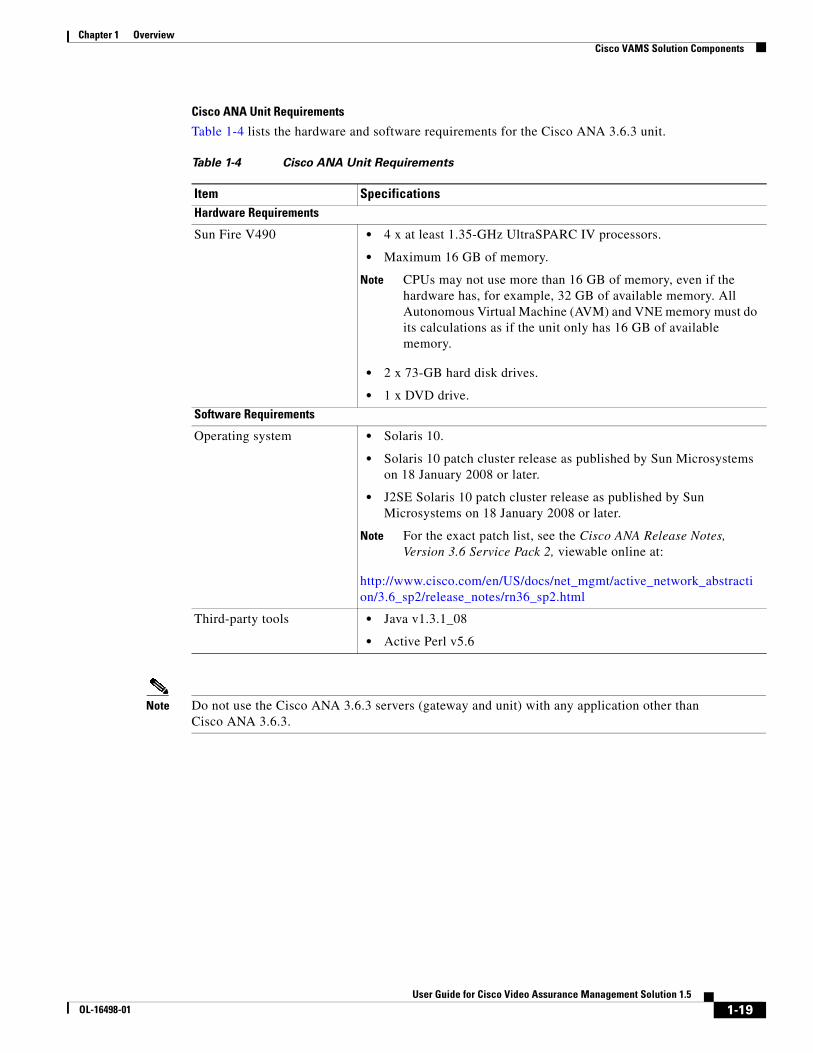
Cisco ANA Unit Requirements
Table 1-4 lists the hardware and software requirements for the Cisco ANA 3.6.3 unit.
Note Do not use the Cisco ANA 3.6.3 servers (gateway and unit) with any application other than Cisco ANA 3.6.3.
Table 1-4 Cisco ANA Unit Requirements
Item SpecificationsHardware Requirements
Sun Fire V490 • 4 x at least 1.35-GHz UltraSPARC IV processors.
• Maximum 16 GB of memory.
Note CPUs may not use more than 16 GB of memory, even if the hardware has, for example, 32 GB of available memory. All Autonomous Virtual Machine (AVM) and VNE memory must do its calculations as if the unit only has 16 GB of available memory.
• 2 x 73-GB hard disk drives.
• 1 x DVD drive.
Software Requirements
Operating system • Solaris 10.
• Solaris 10 patch cluster release as published by Sun Microsystems on 18 January 2008 or later.
• J2SE Solaris 10 patch cluster release as published by Sun Microsystems on 18 January 2008 or later.
Note For the exact patch list, see the Cisco ANA Release Notes, Version 3.6 Service Pack 2, viewable online at:
http://www.cisco.com/en/US/docs/net_mgmt/active_network_abstraction/3.6_sp2/release_notes/rn36_sp2.html
Third-party tools • Java v1.3.1_08
• Active Perl v5.6
1-19User Guide for Cisco Video Assurance Management Solution 1.5
OL-16498-01
Chapter 1 Overview Cisco VAMS Solution Components
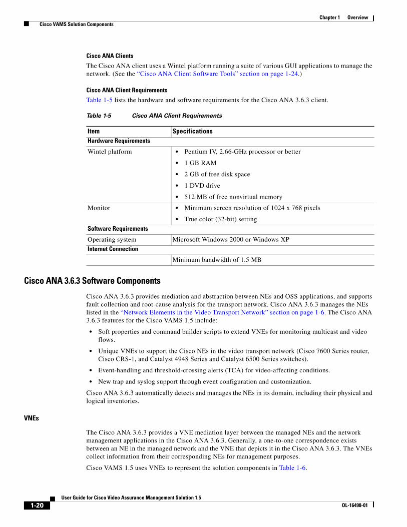
Cisco ANA Clients
The Cisco ANA client uses a Wintel platform running a suite of various GUI applications to manage the network. (See the “Cisco ANA Client Software Tools” section on page 1-24.)
Cisco ANA Client Requirements
Table 1-5 lists the hardware and software requirements for the Cisco ANA 3.6.3 client.
Cisco ANA 3.6.3 Software Components
Cisco ANA 3.6.3 provides mediation and abstraction between NEs and OSS applications, and supports fault collection and root-cause analysis for the transport network. Cisco ANA 3.6.3 manages the NEs listed in the “Network Elements in the Video Transport Network” section on page 1-6. The Cisco ANA 3.6.3 features for the Cisco VAMS 1.5 include:
• Soft properties and command builder scripts to extend VNEs for monitoring multicast and video flows.
• Unique VNEs to support the Cisco NEs in the video transport network (Cisco 7600 Series router, Cisco CRS-1, and Catalyst 4948 Series and Catalyst 6500 Series switches).
• Event-handling and threshold-crossing alerts (TCA) for video-affecting conditions.
• New trap and syslog support through event configuration and customization.
Cisco ANA 3.6.3 automatically detects and manages the NEs in its domain, including their physical and logical inventories.
VNEs
The Cisco ANA 3.6.3 provides a VNE mediation layer between the managed NEs and the network management applications in the Cisco ANA 3.6.3. Generally, a one-to-one correspondence exists between an NE in the managed network and the VNE that depicts it in the Cisco ANA 3.6.3. The VNEs collect information from their corresponding NEs for management purposes.
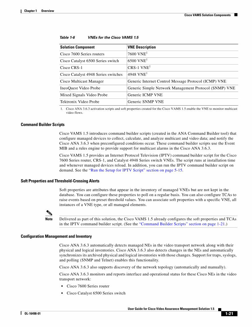
Cisco VAMS 1.5 uses VNEs to represent the solution components in Table 1-6.
Table 1-5 Cisco ANA Client Requirements
Item SpecificationsHardware Requirements
Wintel platform • Pentium IV, 2.66-GHz processor or better
• 1 GB RAM
• 2 GB of free disk space
• 1 DVD drive
• 512 MB of free nonvirtual memory
Monitor • Minimum screen resolution of 1024 x 768 pixels
• True color (32-bit) setting
Software Requirements
Operating system Microsoft Windows 2000 or Windows XP
Internet Connection
Minimum bandwidth of 1.5 MB
1-20User Guide for Cisco Video Assurance Management Solution 1.5
OL-16498-01
Chapter 1 Overview Cisco VAMS Solution Components
Command Builder Scripts
Cisco VAMS 1.5 introduces command builder scripts (created in the ANA Command Builder tool) that configure managed devices to collect, calculate, and analyze multicast and video data; and notify the Cisco ANA 3.6.3 when preconfigured conditions occur. These command builder scripts use the Event MIB and a rules engine to provide support for multicast alarms in the Cisco ANA 3.6.3.
Cisco VAMS 1.5 provides an Internet Protocol Television (IPTV) command builder script for the Cisco 7600 Series router, CRS-1, and Catalyst 4948 Series switch VNEs. The script runs at installation time and whenever managed devices reload. In addition, you can run the IPTV command builder script on demand. See the “Run the Setup for IPTV Script” section on page 5-15.
Soft Properties and Threshold-Crossing Alerts
Soft properties are attributes that appear in the inventory of managed VNEs but are not kept in the database. You can configure these properties to poll on a regular basis. You can also configure TCAs to raise events based on preset threshold values. You can associate soft properties with a specific VNE, all instances of a VNE type, or all managed elements.
Note Delivered as part of this solution, the Cisco VAMS 1.5 already configures the soft properties and TCAs in the IPTV command builder script. (See the “Command Builder Scripts” section on page 1-21.)
Configuration Management and Inventory
Cisco ANA 3.6.3 automatically detects managed NEs in the video transport network along with their physical and logical inventories. Cisco ANA 3.6.3 also detects changes in the NEs and automatically synchronizes its archived physical and logical inventories with those changes. Support for traps, syslogs, and polling (SNMP and Telnet) enables this functionality.
Cisco ANA 3.6.3 also supports discovery of the network topology (automatically and manually).
Cisco ANA 3.6.3 monitors and reports interface and operational status for these Cisco NEs in the video transport network:
• Cisco 7600 Series router
• Cisco Catalyst 6500 Series switch
Table 1-6 VNEs for the Cisco VAMS 1.5
Solution Component VNE Description
Cisco 7600 Series routers 7600 VNE1
1. Cisco ANA 3.6.3 activation scripts and soft properties created for the Cisco VAMS 1.5 enable the VNE to monitor multicast video flows.
Cisco Catalyst 6500 Series switch 6500 VNE1
Cisco CRS-1 CRS-1 VNE1
Cisco Catalyst 4948 Series switches 4948 VNE1
Cisco Multicast Manager Generic Internet Control Message Protocol (ICMP) VNE
IneoQuest Video Probe Generic Simple Network Management Protocol (SNMP) VNE
Mixed Signals Video Probe Generic ICMP VNE
Tektronix Video Probe Generic SNMP VNE
1-21User Guide for Cisco Video Assurance Management Solution 1.5
OL-16498-01
Chapter 1 Overview Cisco VAMS Solution Components
• CRS-1
• Cisco Catalyst 4948 Series switch
This support includes:
• Logical inventory (for example, subinterfaces, VLANs, and routing tables)
• Physical inventory (for example, chassis, cards, and serial numbers)
See the “Network Elements in the Video Transport Network” section on page 1-6, for details about the Cisco NEs.
Fault Management
The Cisco ANA 3.6.3 provides fault management for the video transport network:
• Event and Alarm Management, page 1-22
• Polling and CPU Utilization, page 1-22
• GUIs for Fault Management, page 1-23
See the Cisco ANA Fault Management User Guide 3.6 Service Pack 2 for a description of the Cisco ANA fault management system, viewable online at:
http://www.cisco.com/en/US/docs/net_mgmt/active_network_abstraction/3.6_sp2/fault/user/guide/ chp1.html
Event and Alarm Management
The Cisco ANA 3.6.3 also provides the following event-related features:
• A log of the events.
• Rules-based event processing (for example, to support changing event severities or customize problem descriptions).
• Correlation of events and removal of duplicated events.
• Suppression of events from a particular device or interface.
• Viewing and sorting events (by time and date, severity, or device), switching between multiple event views, and viewing detailed event data.
• Viewing syslog events.
• Changing severity of alarms in the Cisco VAMS 1.5.
Polling and CPU Utilization
Cisco ANA 3.6.3 monitors CPU utilization of the supported NEs in the Cisco VAMS 1.5. You can define polling groups and designate polling intervals for the ANA-managed NEs. The ANA uses an adaptive polling mechanism to ensure that the NEs are not overpolled.
For more information about ANA polling and its interaction with the CPU utilization of managed NEs, see the Cisco ANA Administrator User Guide 3.6 Service Pack 2, viewable online at:
http://www.cisco.com/en/US/docs/net_mgmt/active_network_abstraction/3.6_sp2/administrator/ administration/guide/global.html#wp1041531
Cisco ANA 3.6.3 also supports ICMP to verify that supported NEs are reachable. The ANA VNEs send the ICMP packets to the NEs at a designated rate. You specify the polling rate when you define the VNEs for the Cisco VAMS 1.5.
For more information about ICMP polling, see the Cisco ANA Administrator User Guide 3.6 Service Pack 2, viewable online at:
1-22User Guide for Cisco Video Assurance Management Solution 1.5
OL-16498-01
Chapter 1 Overview Cisco VAMS Solution Components
http://www.cisco.com/en/US/docs/net_mgmt/active_network_abstraction/3.6_sp2/administrator/ administration/guide/manavm.html#wp1041967
Cisco ANA 3.6.3 also provides dynamic, on-demand polling of specific object identifiers (OIDs) by using the ANA Command Builder, a tool which you use to create and run activation scripts.
See the Cisco ANA Command Builder User Guide 3.6 Service Pack 2, viewable online at:
http://www.cisco.com/en/US/docs/net_mgmt/active_network_abstraction/3.6_sp2/command_builder/ developer/guide/cmdbuild-Book-Wrapper.html
GUIs for Fault Management
Cisco ANA 3.6.3 provides GUIs that show NE:
• Status information on the components that this solution supports. (See the “Network Elements in the Video Transport Network” section on page 1-6, for descriptions of the supported NEs.)
• Events, including severity levels and timestamps.
Note Cisco ANA NetworkVision, page 1-25 and Cisco ANA EventVision, page 1-26 are the software tools that provide these GUIs.
Security Management
Cisco ANA 3.6.3 provides user identification and authentication for accessing the Cisco ANA 3.6.3 to perform configuration and fault management tasks on the supported NEs. For more information about security information in Cisco ANA 3.6.3, view the information online at:
http://www.cisco.com/en/US/docs/net_mgmt/active_network_abstraction/3.6/administrator/ mansec.html
Multicast and Video Management
Cisco ANA 3.6.3 provides these multicast and video metrics:
• PIM Alarms, page 1-23
• Multicast Routes, page 1-24
• Non-RPF Drops, page 1-24
PIM Alarms
Cisco ANA creates alarms for events related to Protocol Independent Multicast:(PIM) status changes. The video transport network uses PIM to build a video-specific multicast topology. Therefore, PIM alarms are important for monitoring the status of the solution.
You can view PIM alarms in the ANA EventVision tool. Cisco ANA creates alarms for the following multicast-related SNMP traps:
• pimNeighborLoss—Signifies the loss of an adjacency with a neighbor. The router generates the trap when the neighbor timer expires, and the router has no other neighbors on the same interface with a lower IP address than itself.
• ciscoPimInterfaceUp—Signifies the restoration of a PIM interface.
• ciscoPimInterfaceDown—Signifies the loss of a PIM interface.
1-23User Guide for Cisco Video Assurance Management Solution 1.5
OL-16498-01
Chapter 1 Overview Cisco VAMS Solution Components
Multicast Routes
Cisco ANA uses a VNE soft property to display the number of multicast routes in the device (Cisco 7600 Series router, Cisco CRS-1, or Cisco Catalyst 4948 Series switch). Cisco ANA NetworkVision displays the number of multicast routes on the selected device.
Cisco ANA uses the Event MIB to monitor changes in the number of multicast routes. When the number of multicast routes changes, indicating a possible problem in the video flow, the Event MIB sends an SNMP trap. Cisco ANA receives the trap and creates an event in the Cisco ANA EventVision.
Cisco VAMS 1.5 creates soft properties on VNEs to support viewing:
• Multicast (whether you are enabling an NE for multicast).
• PIM configurations on an interface (whether you are enabling the PIM, the PIM mode, and the designated router (DR) address for the PIM interface).
• IGMP configurations on an interface for a Cisco 7600 router or Catalyst 4948 switch (whether you are enabling the IGMP leave, the IGMP protocol version, or the number of IGMP interface groups).
Note The current Cisco VAMS 1.5 release does not support viewing IGMP status on Cisco CRS-1 NEs.
Non-RPF Drops
Cisco ANA monitors non-Reverse Path Forwarding (non-RPF) drops on each multicast stream. Non-RPF packets, also called RPF failure packets, are RPF packets transmitted backwards, against the flow from the source. Multicast streams include video and non-video streams. If the number of non-RPF drops on a multicast stream exceeds five drops during a polling period, the device sends an SNMP notification. The Cisco ANA 3.6.3 receives the notification and generates an alarm. The Cisco ANA 3.6.3 correlates subsequent alarms and generates subalarms.
Troubleshooting
You perform most fault management tasks through the Cisco ANA 3.6.3 software tools. You perform advanced troubleshooting of the multicast video network by using the CMM 2.5.4. See Chapter 6, “Troubleshooting with the Cisco Video Assurance Management Solution 1.5.”
Cisco ANA Client Software Tools
Cisco ANA 3.6.3 includes several applications built on top of the virtual network as the mediation layer.
Cisco ANA 3.6.3 applications include:
• Cisco ANA Manage, page 1-24
• Cisco ANA NetworkVision, page 1-25
• Cisco ANA EventVision, page 1-26
Cisco ANA Manage
You use the Cisco ANA Manage tool to add, delete, or modify the Cisco NEs in the Layer 2 transport sections of multicast video networks. The administrator configures and controls the Cisco ANA with this GUI tool. The Cisco ANA Manage tool interacts with the Cisco ANA Registry to query and modify configuration information.
Specifically, you use the Cisco ANA Manage tool to perform system administration activities including:
• Adding and removing Cisco ANA units, Autonomous Virtual Machines (AVMs), and VNEs.
• Starting and stopping VNEs.
1-24User Guide for Cisco Video Assurance Management Solution 1.5
OL-16498-01
Chapter 1 Overview Cisco VAMS Solution Components
• Setting polling information per VNE.
• Customizing polling groups and protection groups.
• Managing static and persistent topology links.
• Installing and managing Cisco ANA client licenses.
• Defining and managing user accounts.
See the Cisco ANA Administrators Guide 3.6 Service Pack 2, viewable online at:
http://www.cisco.com/en/US/docs/net_mgmt/active_network_abstraction/3.6_sp2/administrator/ administration/guide/Admin-Book-Wrapper.html
Cisco ANA NetworkVision
You use the Cisco ANA NetworkVision tool (the main GUI for Cisco ANA 3.6.3) to view the network inventory and topology. Cisco ANA NetworkVision displays events, while the mediation layer collects information from the NEs and displays the objects in a topology map. Cisco ANA NetworkVision also displays status and event information (including severities and timestamps) for these supported NEs.
You use the Cisco ANA NetworkVision to:
• View network inventory and multilayer connectivity.
• Troubleshoot, monitor, and manage NEs.
• Model and view network maps maintaining up-to-date topological information on device connections, traffic, and routes.
1-25User Guide for Cisco Video Assurance Management Solution 1.5
OL-16498-01
Chapter 1 Overview Cisco VAMS Solution Components
Network administrators and anyone else responsible for the management, fulfillment, planning, and assurance of the integrity of network resources can use the Cisco NetworkVision tool. See the Cisco ANA NetworkVision User Guide 3.6 Service Pack 2, viewable online at:
http://www.cisco.com/en/US/docs/net_mgmt/active_network_abstraction/3.6_sp2/networkvision/user/guide/nvug.html
Cisco ANA EventVision
You use the Cisco ANA EventVision tool (a GUI for browsing the events in the system) to view and manage alarms, traps, syslogs, provisioning, and system and security events. Monitoring the Cisco ANA EventVision helps predict and identify the sources of network problems, which may prevent future problems.
You can configure Cisco ANA EventVision to display:
• Number of events per page
• Number of events to export to a file
• Filter options
• Information that appears in EventVision tabs
Administrators periodically review and manage the events list by using the Cisco ANA EventVision tool. In addition, when an event occurs in the Cisco ANA 3.6.3 system, Cisco ANA EventVision displays specific details.
See the Cisco ANA EventVision User Guide 3.6 Service Pack 2, viewable online at:
http://www.cisco.com/en/US/docs/net_mgmt/active_network_abstraction/3.6_sp2/eventvision/user/ guide/Event-Book-Wrapper.html
Third-Party Video ProbesCisco VAMS 1.5 supports several third-party probes including the Bridge Technologies, IneoQuest, Mixed Signals, PixelMetrix, and Tektronix video probes. You can add these video quality monitoring probes to key points in the transport network. Functionally, these probes detect impairments and validate the integrity of the Moving Pictures Expert Group (MPEG) transport stream, which carries video.
The video probes communicate with the Cisco VAMS components as follows:
• The video probes communicate traps directly to CIC. When you are viewing a video probe event forwarded by these probes, you can launch CMM diagnostics directly from the CIC interface.
• Certain video probes, such as the IneoQuest probe and the iVMS NMS, communicate traps directly to CMM—CMM can then be configured to forward the traps to CIC.
Cisco VAMS 1.5 receives events from the probes based on thresholds that you configure in the video probes. The Cisco VAMS 1.5 associates probe events with a severity level in Cisco CIC.
Generic VNEs in the Cisco ANA 3.6.3 support the video-monitoring probes. Generic SNMP VNEs handle the IneoQuest and Tektronix probes. A Generic ICMP VNE (no inventory support) handles the Mixed Signals probe.
The video probe VNEs enable the Cisco ANA 3.6.3 to receive SNMP traps from the video probes. (See Appendix A, “Trap Definitions.”)
Note IneoQuest probes are polled directly by the CMM 2.5.4 application.
1-26User Guide for Cisco Video Assurance Management Solution 1.5
OL-16498-01
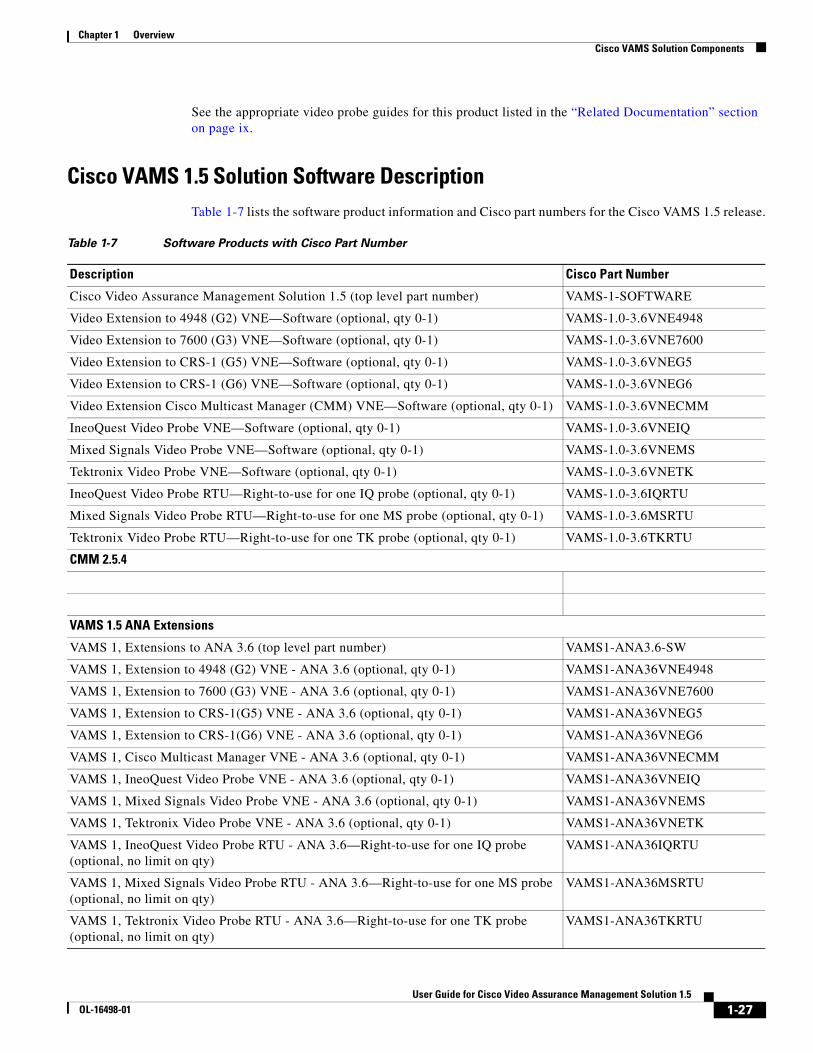
Chapter 1 Overview Cisco VAMS Solution Components
See the appropriate video probe guides for this product listed in the “Related Documentation” section on page ix.
Cisco VAMS 1.5 Solution Software DescriptionTable 1-7 lists the software product information and Cisco part numbers for the Cisco VAMS 1.5 release.
Table 1-7 Software Products with Cisco Part Number
Description Cisco Part Number
Cisco Video Assurance Management Solution 1.5 (top level part number) VAMS-1-SOFTWARE
Video Extension to 4948 (G2) VNE—Software (optional, qty 0-1) VAMS-1.0-3.6VNE4948
Video Extension to 7600 (G3) VNE—Software (optional, qty 0-1) VAMS-1.0-3.6VNE7600
Video Extension to CRS-1 (G5) VNE—Software (optional, qty 0-1) VAMS-1.0-3.6VNEG5
Video Extension to CRS-1 (G6) VNE—Software (optional, qty 0-1) VAMS-1.0-3.6VNEG6
Video Extension Cisco Multicast Manager (CMM) VNE—Software (optional, qty 0-1) VAMS-1.0-3.6VNECMM
IneoQuest Video Probe VNE—Software (optional, qty 0-1) VAMS-1.0-3.6VNEIQ
Mixed Signals Video Probe VNE—Software (optional, qty 0-1) VAMS-1.0-3.6VNEMS
Tektronix Video Probe VNE—Software (optional, qty 0-1) VAMS-1.0-3.6VNETK
IneoQuest Video Probe RTU—Right-to-use for one IQ probe (optional, qty 0-1) VAMS-1.0-3.6IQRTU
Mixed Signals Video Probe RTU—Right-to-use for one MS probe (optional, qty 0-1) VAMS-1.0-3.6MSRTU
Tektronix Video Probe RTU—Right-to-use for one TK probe (optional, qty 0-1) VAMS-1.0-3.6TKRTU
CMM 2.5.4
VAMS 1.5 ANA Extensions
VAMS 1, Extensions to ANA 3.6 (top level part number) VAMS1-ANA3.6-SW
VAMS 1, Extension to 4948 (G2) VNE - ANA 3.6 (optional, qty 0-1) VAMS1-ANA36VNE4948
VAMS 1, Extension to 7600 (G3) VNE - ANA 3.6 (optional, qty 0-1) VAMS1-ANA36VNE7600
VAMS 1, Extension to CRS-1(G5) VNE - ANA 3.6 (optional, qty 0-1) VAMS1-ANA36VNEG5
VAMS 1, Extension to CRS-1(G6) VNE - ANA 3.6 (optional, qty 0-1) VAMS1-ANA36VNEG6
VAMS 1, Cisco Multicast Manager VNE - ANA 3.6 (optional, qty 0-1) VAMS1-ANA36VNECMM
VAMS 1, IneoQuest Video Probe VNE - ANA 3.6 (optional, qty 0-1) VAMS1-ANA36VNEIQ
VAMS 1, Mixed Signals Video Probe VNE - ANA 3.6 (optional, qty 0-1) VAMS1-ANA36VNEMS
VAMS 1, Tektronix Video Probe VNE - ANA 3.6 (optional, qty 0-1) VAMS1-ANA36VNETK
VAMS 1, IneoQuest Video Probe RTU - ANA 3.6—Right-to-use for one IQ probe (optional, no limit on qty)
VAMS1-ANA36IQRTU
VAMS 1, Mixed Signals Video Probe RTU - ANA 3.6—Right-to-use for one MS probe (optional, no limit on qty)
VAMS1-ANA36MSRTU
VAMS 1, Tektronix Video Probe RTU - ANA 3.6—Right-to-use for one TK probe (optional, no limit on qty)
VAMS1-ANA36TKRTU
1-27User Guide for Cisco Video Assurance Management Solution 1.5
OL-16498-01
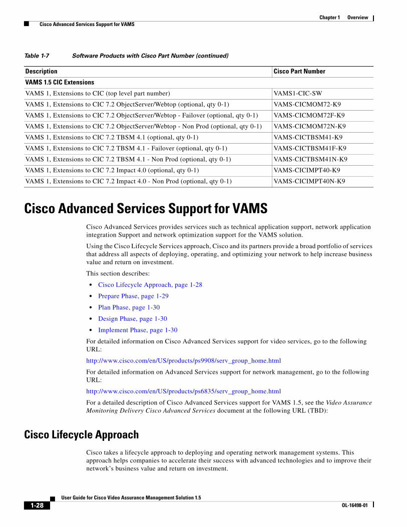
Chapter 1 Overview Cisco Advanced Services Support for VAMS
Cisco Advanced Services Support for VAMSCisco Advanced Services provides services such as technical application support, network application integration Support and network optimization support for the VAMS solution.
Using the Cisco Lifecycle Services approach, Cisco and its partners provide a broad portfolio of services that address all aspects of deploying, operating, and optimizing your network to help increase business value and return on investment.
This section describes:
• Cisco Lifecycle Approach, page 1-28
• Prepare Phase, page 1-29
• Plan Phase, page 1-30
• Design Phase, page 1-30
• Implement Phase, page 1-30
For detailed information on Cisco Advanced Services support for video services, go to the following URL:
http://www.cisco.com/en/US/products/ps9908/serv_group_home.html
For detailed information on Advanced Services support for network management, go to the following URL:
http://www.cisco.com/en/US/products/ps6835/serv_group_home.html
For a detailed description of Cisco Advanced Services support for VAMS 1.5, see the Video Assurance Monitoring Delivery Cisco Advanced Services document at the following URL (TBD):
Cisco Lifecycle ApproachCisco takes a lifecycle approach to deploying and operating network management systems. This approach helps companies to accelerate their success with advanced technologies and to improve their network’s business value and return on investment.
VAMS 1.5 CIC Extensions
VAMS 1, Extensions to CIC (top level part number) VAMS1-CIC-SW
VAMS 1, Extensions to CIC 7.2 ObjectServer/Webtop (optional, qty 0-1) VAMS-CICMOM72-K9
VAMS 1, Extensions to CIC 7.2 ObjectServer/Webtop - Failover (optional, qty 0-1) VAMS-CICMOM72F-K9
VAMS 1, Extensions to CIC 7.2 ObjectServer/Webtop - Non Prod (optional, qty 0-1) VAMS-CICMOM72N-K9
VAMS 1, Extensions to CIC 7.2 TBSM 4.1 (optional, qty 0-1) VAMS-CICTBSM41-K9
VAMS 1, Extensions to CIC 7.2 TBSM 4.1 - Failover (optional, qty 0-1) VAMS-CICTBSM41F-K9
VAMS 1, Extensions to CIC 7.2 TBSM 4.1 - Non Prod (optional, qty 0-1) VAMS-CICTBSM41N-K9
VAMS 1, Extensions to CIC 7.2 Impact 4.0 (optional, qty 0-1) VAMS-CICIMPT40-K9
VAMS 1, Extensions to CIC 7.2 Impact 4.0 - Non Prod (optional, qty 0-1) VAMS-CICIMPT40N-K9
Table 1-7 Software Products with Cisco Part Number (continued)
Description Cisco Part Number
1-28User Guide for Cisco Video Assurance Management Solution 1.5
OL-16498-01
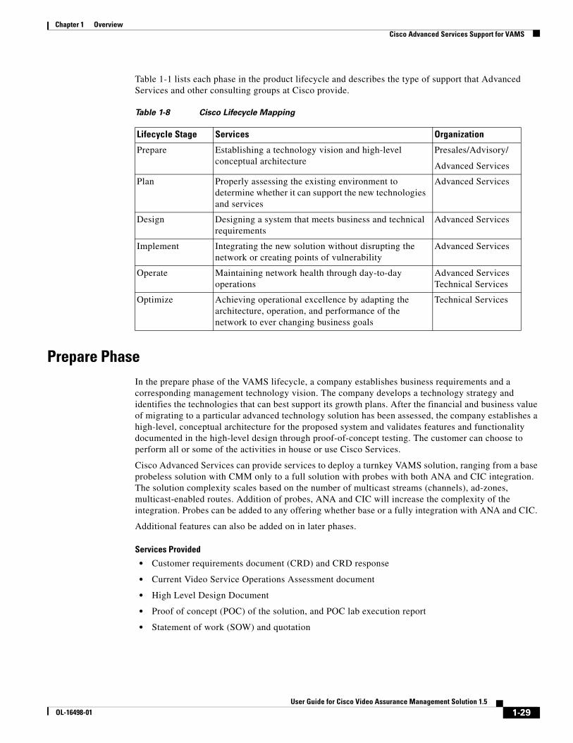
Chapter 1 Overview Cisco Advanced Services Support for VAMS
Table 1-1 lists each phase in the product lifecycle and describes the type of support that Advanced Services and other consulting groups at Cisco provide.
Prepare PhaseIn the prepare phase of the VAMS lifecycle, a company establishes business requirements and a corresponding management technology vision. The company develops a technology strategy and identifies the technologies that can best support its growth plans. After the financial and business value of migrating to a particular advanced technology solution has been assessed, the company establishes a high-level, conceptual architecture for the proposed system and validates features and functionality documented in the high-level design through proof-of-concept testing. The customer can choose to perform all or some of the activities in house or use Cisco Services.
Cisco Advanced Services can provide services to deploy a turnkey VAMS solution, ranging from a base probeless solution with CMM only to a full solution with probes with both ANA and CIC integration. The solution complexity scales based on the number of multicast streams (channels), ad-zones, multicast-enabled routes. Addition of probes, ANA and CIC will increase the complexity of the integration. Probes can be added to any offering whether base or a fully integration with ANA and CIC.
Additional features can also be added on in later phases.
Services Provided
• Customer requirements document (CRD) and CRD response
• Current Video Service Operations Assessment document
• High Level Design Document
• Proof of concept (POC) of the solution, and POC lab execution report
• Statement of work (SOW) and quotation
Table 1-8 Cisco Lifecycle Mapping
Lifecycle Stage Services Organization
Prepare Establishing a technology vision and high-level conceptual architecture
Presales/Advisory/
Advanced Services
Plan Properly assessing the existing environment to determine whether it can support the new technologies and services
Advanced Services
Design Designing a system that meets business and technical requirements
Advanced Services
Implement Integrating the new solution without disrupting the network or creating points of vulnerability
Advanced Services
Operate Maintaining network health through day-to-day operations
Advanced Services Technical Services
Optimize Achieving operational excellence by adapting the architecture, operation, and performance of the network to ever changing business goals
Technical Services
1-29User Guide for Cisco Video Assurance Management Solution 1.5
OL-16498-01
Chapter 1 Overview Cisco Advanced Services Support for VAMS
Plan PhaseIn the plan phase of the lifecycle, the organization tries to make sure that adequate resources are available to manage the technology deployment project from planning through design and implementation. A project plan is created to help manage the tasks, risk, problems, responsibilities, critical milestones, and resources required to implement VAMS solution into the production network.
Services Provided
• Data collection of channel-lineup, ad-zone, and multicast addresses for the video flows (Base offering, CMM only). A spreadsheet summarizing the collected data.
• Data collection regarding MPEG probes parameters and associated alarm thresholds. (probes only).
• Data collection regarding ANA managed nodes and alarm thresholds (ANA only).
• Data collection regarding VAMS CIC-specific data. (CIC).
• Gaps and recommendation to gaps document.
• VAMS program and project management: Aligns with the scope, cost, and resource parameters in the original business requirements established during the prepare phase.
• An overall project management plan (PMP).
• VAMS site readiness report.
Design PhaseDuring the design phase of the VAM lifecycle, Cisco validates the proposed high level design and develops a low level design to the specified customer requirements and data. During the design phase, Cisco Network Consulting Engineers create a variety of plans and documents to guide activities such as configuring, deploying, and commissioning the proposed system.
Services Provided
• VAMS design development (CMM, probes, ANA and/or CIC) and associated Low-Level Design (LLD) documents.
• VAMS test plan development (CMM, probes, ANA, and/or CIC.
• VAMS implementation plan.
• VAMS design validation and review.
• Probes placement methodology.
• Network management for probes.
• Probe configuration.
• Probe network management plan.
• ANA-plug in configuration for VAMS (ANA).
• Specific configuration for CIC.
Implement Phase
In the implementation phase, Cisco Advanced Services integrates systems without disrupting the existing network or creating points of vulnerability. Cisco configures and integrates system components, and installs,
1-30User Guide for Cisco Video Assurance Management Solution 1.5
OL-16498-01
Chapter 1 Overview Cisco Advanced Services Support for VAMS
configures, tests, and commissions the VAMS system. After installation, Cisco validates that its operational network is working as intended, validates system operations, and works to close gaps in staff skills
Services Provided
• Site readiness review.
• CMM installation and configuration.
• Discovery of the multicast devices.
• Configuration, testing, and adjustment of critical flows and multicast thresholds.
• Configuration, testing, and adjustment of MPEG thresholds (probes only). Customer performs physical installation of probes.
• Implementation and configuration of the ANA VAMS plug-in (ANA only)
• Implementation of CIC plug-in (CIC only).
• Test plan execution.
• CMM cases.
• Probes cases.
• ANA VAMS-plug in cases.
• CIC-plug in cases.
• AS build documents and support for on-site knowledge transfer.
1-31User Guide for Cisco Video Assurance Management Solution 1.5
OL-16498-01

Chapter 1 Overview Cisco Advanced Services Support for VAMS
1-32User Guide for Cisco Video Assurance Management Solution 1.5
OL-16498-01
User Guide foOL-16498-01
C H A P T E R 2
PreinstallationPrerequisitesYour system must have the following hardware and software before installing the Cisco VAMS 1.5 software package:
Note See the “Install and Configure Prerequisite Hardware and Software Solution Components” section on page 2-2 for detailed installation procedures.
Hardware Installation
• The core network elements of the video transport network:
– Cisco 7600 Series router
– Cisco Catalyst 6500 Series switch
– Cisco CRS-1
– Cisco Catalyst 4948 Series switch
• Management servers for Cisco Active Network Abstraction (ANA) 3.6.3 (includes gateway, unit, and client installation).
• Management servers for Cisco Multicast Manager (CMM) 2.5.4.
• Third-party video probes:
– Bridge Technologies VB Series
– IneoQuest Singulus G1-T and IQ Cricket
– Mixed Signals Sentry Digital Content Monitor
– Pixelmetrix DVStation
– Tektronix MTM400
• Management servers for Cisco Info Center/Netcool 7.2 Suite.
Software Installation
• The IPTV-enabled IOS software versions:
– 12.2(33)SRB2, 12.2(33)SRB3, 12.2(33)SRC, or 12.2(33)SRC1on the Cisco 7600 Series router
– 12.2(33)SRB2, 12.2(33)SRB3, 12.2(33)SRC, or 12.2(33)SRC1on the Cisco Catalyst 6500 Series switch
2-1r Cisco Video Assurance Management Solution 1.5
Chapter 2 Preinstallation Prerequisites
– IOS-XR 3.6.1.12 on the Cisco CRS-1
– 12.2(31)SGA1 on the Cisco Catalyst 4948 Series switch
• Cisco ANA 3.6.3 (includes gateway, unit, and client installation).
• Cisco Multicast Manager (CMM) 2.5.4 software on dedicated server.
• Management software for the Cisco Info Center/Netcool 7.2 suite:
– ObjectServer 7.2
– Webtop 2.1
– Impact 4.0
– TBSM 4.1
Install and Configure Prerequisite Hardware and Software Solution Components
Before installing the Cisco VAMS 1.5 software package:
Note Perform these tasks in the sequence shown.
Step 1 Install the Cisco 7600 Series routers, Cisco Catalyst 6500 switches, Cisco CRS-1, and Cisco Catalyst 4948 Series switches for the supported cable or wireline architecture.
See the following installation guides for more information:
• Cisco 7600 Series installation guides, viewable online at: http://www.cisco.com/en/US/products/hw/routers/ps368/prod_installation_guides_list.html
• Cisco Catalyst 6500 Series installation guides, viewable online at: http://www.cisco.com/en/US/products/hw/switches/ps708/prod_installation_guides_list.html
• Cisco CRS-1 installation guides, viewable online at: http://www.cisco.com/en/US/products/ps5763/prod_installation_guides_list.html
• Cisco Catalyst 4948 installation guides, viewable online at: http://www.cisco.com/en/US/docs/switches/lan/catalyst4900/4948-10ge/4948_10.html
Step 2 Configure the Cisco 7600 Series routers, Cisco Catalyst 6500 Series switches, Cisco CRS-1, and Cisco Catalyst 4948 Series switches for the supported cable or wireline architecture.
See the following configuration guides for more information:
• Cisco 7600 Series configuration guides, viewable online at: http://www.cisco.com/en/US/products/hw/routers/ps368/products_installation_and_configuration _guides_list.html
• Cisco Catalyst 6500 Series configuration guides, viewable online at: http://www.cisco.com/en/US/products/hw/switches/ps708/products_installation_and_ configuration_guides_list.html
• Cisco CRS-1 configuration guides, viewable online at: http://www.cisco.com/en/US/products/ps5763/products_installation_and_configuration_guides _list.html
2-2User Guide for Cisco Video Assurance Management Solution 1.5
OL-16498-01
Chapter 2 Preinstallation Prerequisites
• Cisco Catalyst 4948 configuration guides, viewable online at: http://www.cisco.com/en/US/docs/switches/lan/catalyst4500/12.2/25ewa/configuration/guide/ conf.html
http://www.cisco.com/en/US/docs/switches/lan/catalyst4500/12.2/31sg/configuration/guide/ conf.html
• Also, consult configuration tasks documented in the “Cisco Internet Protocol Television (IPTV) Solutions” section on page xiii.
Step 3 Install the following multicast-enabled IOS images1:
• Cisco 7600 Series routers with 12.2(33)SRB2, 12.2(33)SRB3, or 12.2(33)SRC1 image
• Cisco Catalyst 6500 Series switches with 12.2(33)SRB2, 12.2(33)SRB3, or 12.2(33)SRC1 image
• Cisco CRS-1 with IOS-XR 3.6.1.12 image
• Cisco Catalyst 4948 Series switches with 12.2(31)SGA1 image
See the following release notes for more information:
• Cisco 7600 release notes, viewable online at: http://www.cisco.com/en/US/products/ps6922/prod_release_note09186a00806c096f.html
• Cisco Catalyst 6500 release notes, viewable online at: http://www.cisco.com/en/US/products/hw/switches/ps708/prod_release_notes_list.html
• Cisco CRS-1 release notes, viewable online at: http://www.cisco.com/en/US/docs/ios_xr_sw/iosxr_r3.4/general/release/notes/reln_342.html
• Cisco Catalyst 4948 release notes, viewable online at: http://www.cisco.com/en/US/docs/switches/lan/catalyst4500/release/note/OL_9592.html
Step 4 Install the Active Network Abstraction (ANA) hardware and software on dedicated servers (includes gateway, unit, and client installation and ANA 3.6.1, 3.6.2, and 3.6.3 updates):
See the following installation guides for more information:
• Cisco Active Network Abstraction Installation Guide 3.6, viewable online at: http://www.cisco.com/en/US/docs/net_mgmt/active_network_abstraction/3.6/installation/ install_1.html
• Cisco Active Network Abstraction Installation Guide 3.6 Service Pack 1, viewable online at: http://www.cisco.com/en/US/docs/net_mgmt/active_network_abstraction/3.6_sp1/installation/ guide/Install-Book-Wrapper.html).
• Cisco Active Network Abstraction Installation Guide 3.6 Service Pack 22, viewable online at: http://www.cisco.com/en/US/docs/net_mgmt/active_network_abstraction/3.6_sp2/installation/ guide/Install-Book-Wrapper.html
• Cisco Active Network Abstraction Installation Guide 3.6 Service Pack 3, viewable online at: http://www.cisco.com/en/US/docs/net_mgmt/active_network_abstraction/3.6_sp3/installation/guide/Install-Book-Wrapper.html
Step 5 Install the Cisco Multicast Manager (CMM) 2.5.4 hardware and software on dedicated servers:
See the following installation guide for more information:
Cisco Multicast Manager Installation Guide 2.5, viewable online at: http://www.cisco.com/en/US/products/ps6337/prod_installation_guides_list.html
1. Download the Cisco IOS software from http://www.cisco.com/public/sw-center/index.shtml.
2. If you encounter an error during installation of ANA 3.6.2, follow the workaround described here: http://www.cisco.com/en/US/docs/net_mgmt/active_network_abstraction/3.6_sp2/release_notes /rn36_sp2.htm#wp82640
2-3User Guide for Cisco Video Assurance Management Solution 1.5
OL-16498-01
Chapter 2 Preinstallation Prerequisites
Step 6 Install the third-party video probes for Bridge Technologies, IneoQuest, Mixed Signals, PixelMetrix and Tektronix:
See the following video probe guides for more information:
Bridge Technologies
VB120 Broadcast IP-Probe User’s Manual v. 4.0.
IneoQuest Singulus G1-T
• IQMedia QuickStart Guide
• IQ MediaMonitor Series M1 Singulus G1-T Network Monitoring and Analysis Systems Hardware User’s Guide
• IQMediaAnalyzer Application User’s Guide
IneoQuest Cricket
See the IneoQuest website for more information.
Mixed Signals Sentry
Mixed Signals Sentry Digital Content Monitor User Guide
PixelMetrix
DVStation-IP-3 User Manual, Software Version 4.17
Tektronix MTM400
• MTM400 MPEG Transport Stream Monitor User Manual
• MTM400 MPEG Transport Stream Monitor Technical Reference
• MTM400 MPEG Transport Stream Monitor Programmer Manual
Step 7 Install the hardware and software for the Cisco Info Center/Netcool 7.2 on dedicated servers:
See the following books for more information:
Documentation Guide and Supplemental License Agreement
Cisco Info Center 7.1 Documentation Guide and Supplemental Licence Agreement
Viewable online at:
http://www.cisco.com/en/US/products/sw/netmgtsw/ps996/products_documentation_roadmap09186a0080805796.html
IBM Tivoli Netcool/OMNIbus
IBM Tivoli Netcool/OMNIbus Installation and Dployment Guide
IBM Tivoli Netcool/Webtop
• IBM Tivoli Netcool/Webtop QuickStart Guide
• IBM Tivoli Netcool/Webtop Administration Guide
2-4User Guide for Cisco Video Assurance Management Solution 1.5
OL-16498-01
Chapter 2 Preinstallation Prerequisites
IBM Tivoli Netcool/Impact
• IBM Tivoli Netcool/Impact Administration Guide
• IBM Tivoli Netcool/Impact User Interface Guide
• IBM Tivoli Netcool/Impact Solutions Guide
IBM Tivoli Business Service Manager
• IBM Tivoli Business Service Manager Installation Guide
• IBM Tivoli Business Service Manager Quick Start
• IBM Tivoli Business Service Manager Administrator’s Guide
• IBM Tivoli Business Service Manager Service Configuration Guide
• IBM Tivoli Business Service Manager Customization Guide
IBM Netcool GUI Foundation
Netcool GUI Foundation Version 1.1 Administration Guide
2-5User Guide for Cisco Video Assurance Management Solution 1.5
OL-16498-01

Chapter 2 Preinstallation Prerequisites
2-6User Guide for Cisco Video Assurance Management Solution 1.5
OL-16498-01
User Guide foOL-16498-01
C H A P T E R 3
Installing the Cisco Video Assurance Management Solution 1.5Before You Install
Note You must meet all preinstallation tasks listed in Chapter 2, “Preinstallation” before continuing. Complete these tasks before installing the Cisco VAMS 1.5 software package.
Release NotesBefore you install the Cisco VAMS 1.5, refer to the latest release notes for this solution, available online at Cisco.com. The release notes contain additional information that became available after the initial release of the solution.
Each release note contains:
• Upgrade notes—additional information and considerations for upgrading.
• Uninstalling software—detailed instructions for removing previous installations of software.
• Patch releases and enhancements—describes any enhancements provided by patches.
• Open and resolved caveats—describes any expected behavior that may or may not require a workaround.
• Other configuration requirements.
Install the Cisco VAMS 1.5 SoftwareTo install the Cisco VAMS 1.5:
Step 1 Log in to the server as the root user.
Step 2 Insert the Cisco VAMS 1.5 installation DVD into the DVD drive on your system.
Step 3 Check the system prerequisites such as required disk space. See Chapter 1, “Overview.”
Step 4 If an older version of the Cisco VAMS exists, uninstall it. See Chapter 4, “Uninstalling the Cisco Video Assurance Management Solution 1.5.”
3-1r Cisco Video Assurance Management Solution 1.5
Chapter 3 Installing the Cisco Video Assurance Management Solution 1.5 Install the Cisco VAMS 1.5 Software
Step 5 Change the directory to the root directory on the DVD.
For example:
cd /cdrom/cdrom0/
Step 6 Start the installation script.
For example:
./install.sh -o
The installation script prompts you to enter site-specific values for the installation.
Step 7 When prompted to enter login information for the Cisco ANA, you must enter an administrative-level user ID and password. If necessary, obtain this information from your administrator.
Step 8 If your login information does not authenticate, retry by entering r, or bypass the Cisco ANA authentication by entering y.
The specified login and password do not authenticate.Do you wish to continue with the installation? [Y(es)/N(o)/R(etry)]:
Caution If you enter y to bypass authentication, you must run the setCimsCredentials.sh script later. That script is in the iptv/scripts/ directory. The Cisco VAMS 1.5 will not operate correctly if you do not run the setCimsCredentials.sh script after a failed authentication.
Step 9 After successful installation, continue to Chapter 5, “Configuring the Components of the Cisco Video Assurance Management Solution 1.5.”
A message similar to this one should appear on your screen:
Installation of <CSCOcims> was successful.Modifying configuration filespreparing client configuration..updating client configuration..Restarting ANA Gateway...Installation completed.
3-2User Guide for Cisco Video Assurance Management Solution 1.5
OL-16498-01
User Guide foOL-16498-01
C H A P T E R 4
Uninstalling the Cisco Video Assurance Management Solution 1.5Uninstall Cisco VAMS 1.5
Note You can also use this procedure to uninstall a previous version of the Cisco VAMS software.
To uninstall Cisco VAMS 1.5:
Step 1 Log in to the server as the root user.
Step 2 Insert the Cisco VAMS 1.5 installation DVD into the DVD drive on your system.
Step 3 Change the directory to the uninstallation directory.
For example:
cd $ANAROOT/iptv/scripts
where $ANAROOT is the ANA installation directory.
Step 4 Start the uninstall script.
./uninstall.sh
Do you want to remove this package? [y,n,?,q] ?
Step 5 Enter y to continue. A message similar to this one should appear on your screen:
## Removing installed package instance <CSCOcims>## Verifying package <CSCOcims> dependencies in global zone## Processing package information.## Executing preremove script.Restoring configuration file...
Restarting ANA Gateway...
Removal of <CSCOcims> was successful.
4-1r Cisco Video Assurance Management Solution 1.5

Chapter 4 Uninstalling the Cisco Video Assurance Management Solution 1.5 Uninstall Cisco VAMS 1.5
4-2User Guide for Cisco Video Assurance Management Solution 1.5
OL-16498-01
User Guide foOL-16498-01
C H A P T E R 5
Configuring the Components of the Cisco Video Assurance Management Solution 1.5After completing the installation of Cisco VAMS 1.5, you are ready to configure the components of the solution for operation.
The following summary procedure describes how to configure all the components of the Cisco VAMS 1.5. References to more detailed procedures and documentation are provided.
To configure the components of the Cisco VAMS 1.5:
Step 1 Ensure that you have met all prerequisites. (See Chapter 2, “Preinstallation.” and the “Before You Install” section on page 3-1.)
Note As an important prerequisite, load all the Cisco devices in the video transport network with IOS software that supports the Cisco VAMS 1.5.
Step 2 In Cisco ANA, create new virtual network elements (VNEs) for the Cisco VAMS 1.5 components. See the “Create VNEs” section on page 5-2.
Step 3 Add the Cisco VAMS 1.5 devices to the Cisco ANA network map. See the “Add Solution Components to the Cisco ANA Network Map” section on page 5-4.
Step 4 Configure the CMM to set thresholds and forward notifications to the CIC Object Server. Configure the following types of monitoring:
• PPS/BPS Threshold Polling
• Tree Polling
• Health Checks
• IP Multicast Heartbeat Monitoring
See the “Configure the CMM” section on page 5-5.
Step 5 Configure the video probes to set thresholds and send events to Cisco ANA. See the “Configure Video Probes” section on page 5-14.
Note All components of the Cisco VAMS 1.5 are now operational. The Cisco devices in the video transport network forward notifications to the CMM, which then forwards them to the Cisco ANA. The video probes also forward notifications to the Cisco ANA. The remaining steps of this procedure are optional.
5-1r Cisco Video Assurance Management Solution 1.5
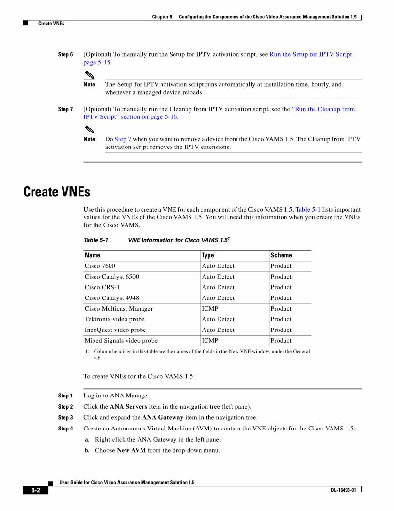
Chapter 5 Configuring the Components of the Cisco Video Assurance Management Solution 1.5 Create VNEs
Step 6 (Optional) To manually run the Setup for IPTV activation script, see Run the Setup for IPTV Script, page 5-15.
Note The Setup for IPTV activation script runs automatically at installation time, hourly, and whenever a managed device reloads.
Step 7 (Optional) To manually run the Cleanup from IPTV activation script, see the “Run the Cleanup from IPTV Script” section on page 5-16.
Note Do Step 7 when you want to remove a device from the Cisco VAMS 1.5. The Cleanup from IPTV activation script removes the IPTV extensions.
Create VNEs Use this procedure to create a VNE for each component of the Cisco VAMS 1.5. Table 5-1 lists important values for the VNEs of the Cisco VAMS 1.5. You will need this information when you create the VNEs for the Cisco VAMS.
To create VNEs for the Cisco VAMS 1.5:
Step 1 Log in to ANA Manage.
Step 2 Click the ANA Servers item in the navigation tree (left pane).
Step 3 Click and expand the ANA Gateway item in the navigation tree.
Step 4 Create an Autonomous Virtual Machine (AVM) to contain the VNE objects for the Cisco VAMS 1.5:
a. Right-click the ANA Gateway in the left pane.
b. Choose New AVM from the drop-down menu.
Table 5-1 VNE Information for Cisco VAMS 1.51
1. Column headings in this table are the names of the fields in the New VNE window, under the General tab.
Name Type Scheme
Cisco 7600 Auto Detect Product
Cisco Catalyst 6500 Auto Detect Product
Cisco CRS-1 Auto Detect Product
Cisco Catalyst 4948 Auto Detect Product
Cisco Multicast Manager ICMP Product
Tektronix video probe Auto Detect Product
IneoQuest video probe Auto Detect Product
Mixed Signals video probe ICMP Product
5-2User Guide for Cisco Video Assurance Management Solution 1.5
OL-16498-01
Chapter 5 Configuring the Components of the Cisco Video Assurance Management Solution 1.5 Create VNEs
c. Enter an ID number and key.
d. Check the Activate on creation check box and click OK.
Note You may create more than one AVM. For example, you could create one AVM for the Cisco devices and a different AVM for the video probes.
Step 5 Right-click the AVM that contains the IPTV devices, then, choose the New VNE.
Step 6 Complete these fields in the New VNE window under the General tab:
• Name (as ANA identifies it)
• IP Address
• Type (see Table 5-1 on page 5-2)
• Scheme (see Table 5-1 on page 5-2)
• Initial State (Stop or Start)
Step 7 Under the SNMP tab, in the SNMP V1/V2 Settings pane, complete these fields:
• Community Read
• Community Write
Step 8 Enable Telnet or SSH under the Telnet/SSH tab. This information enables discovery of the device.
Step 9 If the VNE type is ICMP (see Table 5-1 on page 5-2), enter a polling rate under the ICMP tab.
Step 10 If required, add the VNE to a polling group under the Polling tab.
Note The IPTV extensions of the Cisco VAMS 1.5 provide two new polling groups: 30-minute config and 60-minute config. Depending on your polling requirements, choose one of these groups to obtain status, configuration, and system information.
Step 11 Enter any other required information in the remaining tabs of the New VNE window and click OK.
Step 12 Verify that the new VNE appears in the VNEs table in the right pane of the ANA Manage window.
Step 13 To start the new VNE, right-click it in the table and choose Actions > Start.
Step 14 To continue to add new VNEs, repeat this procedure from Step 5.
5-3User Guide for Cisco Video Assurance Management Solution 1.5
OL-16498-01
Chapter 5 Configuring the Components of the Cisco Video Assurance Management Solution 1.5 Add Solution Components to the Cisco ANA Network Map
Add Solution Components to the Cisco ANA Network MapUse this procedure to add these components to the Cisco ANA Network Map:
• Cisco 7600 Series router
• Cisco Catalyst 6500 switch
• Cisco CRS-1
• Cisco Catalyst 4948 Series switch
• Video probes:
– Bridge Technologies
– IneoQuest
– Mixed Signals
– PixelMetrix
– Tektronix
• Cisco Multicast Manager
To add the previous components:
Step 1 Log in to ANA NetworkVision.
Step 2 If you have not already, create a new network map:
File > New Map
Step 3 To open the device list, choose File > Add Device.
Step 4 Choose the device that you want to add to the network map.
Step 5 Click Add Device.
Step 6 Verify that the device appears in the network map and links appear between connected devices.
Note If links do not appear and the devices are connected, you can manually create the links as described in the Release Notes for Cisco Active Network Abstraction 3.6 Service Pack 2: http://www.cisco.com/en/US/docs/net_mgmt/active_network_abstraction/3.6_sp2/release_notes/rn36_sp2.html (see defect CSCsi50166).
Step 7 To add other solution components to the network map, repeat this procedure from Step 3.
5-4User Guide for Cisco Video Assurance Management Solution 1.5
OL-16498-01
Chapter 5 Configuring the Components of the Cisco Video Assurance Management Solution 1.5 Configure the CMM
Configure the CMMTo enable notifications and set thresholds for multicast conditions, you must configure the CMM.
This section covers two areas of CMM Configuration:
• General CMM Configuration, page 5-5—This section covers general configuration of CMM.
• Setting Up Troubleshooting Configuration for IP Multicast, page 5-6—This section describes configuration of CMM for specific types of monitoring:
– Configuring BPS/PPS Threshold Monitoring, page 5-6.
– Configuring Tree Polling, page 5-8.
– Configuring Health Checks, page 5-11
– Configuring IP Multicast Heartbeat Monitoring, page 5-13
General CMM ConfigurationGeneral Configuration tasks for CMM include:
• Discovery of multicast-capable devices in the domain.
• Global configuration of polling intervals and run times for Layer 2 polling, Designated Router (DR) polling, and polling of Rendezvous Point (RP) status.
• Configuration of video probes.
• Configuration of the Channel Mapping database.
Note A summary procedure of configuration tasks follows. For complete details about these, and other configuration tasks, see the User Guide for the Cisco Multicast Manager 2.5:
http://www.cisco.com/en/US/docs/net_mgmt/cisco_multicast_manager/2.5/user/guide/CMM_25_User_Guide.html
To configure the CMM for the Cisco VAMS 1.5:
Step 1 In a browser window, open and log in to the CMM.
Step 2 In the Tool drop-down menu, click Administration.
Step 3 To add a domain, choose Domain Management.
Step 4 Choose add a new domain. The System Configuration page appears.
Step 5 To discover the devices, choose Discovery > Multicast.
Step 6 To add Video probes, choose Discovery > Add Video Probe.
Step 7 To configure multicast thresholds, choose Multicast Polling Configuration. To activate your changes, click the Start button.
Step 8 To configure polling intervals and run times, choose Global Polling Configuration. To activate your changes, click the Start button.
Step 9 To configure the Channel Mapping databases, choose Address Management and configure the Channel Map database, the Multiplex Table Database, the Ad Zone database, and the Address database.
5-5User Guide for Cisco Video Assurance Management Solution 1.5
OL-16498-01
Chapter 5 Configuring the Components of the Cisco Video Assurance Management Solution 1.5 Configure the CMM
Step 10 Forward notifications to CIC:
a. Choose Global Polling Configuration > Domain Trap/Email.
b. In the right pane, enter the IP address of the CIC Object Server in the Add Trap Receiver field.
c. Click the Add Trap Receiver button. This action adds the CIC Object Server IP address to the Configured Trap Receivers drop-down list.
d. Choose a trap receiver from the Configured Trap Receivers drop-down list.
e. To activate your changes, click the Start button.
The CMM forwards notifications to CIC, the designated trap receiver.
Step 11 To add users, choose User Management > Manage Users.
Setting Up Troubleshooting Configuration for IP MulticastConfiguring IP multicast configuration settings in CMM for VAMS 1.5 includes the following tasks:
• Configuring BPS/PPS Threshold Monitoring, page 5-6
• Configuring Tree Polling, page 5-8
• Configuring Health Checks, page 5-11
• Configuring IP Multicast Heartbeat Monitoring, page 5-13
Configuring BPS/PPS Threshold Monitoring
Cisco VAMS 1.5, which includes CMM 2.5.4. enables polling of flows from Cisco 7600 routers and Cisco 6500 devices without the use of video probes. This is referred to as probeless monitoring.
To configure probeless monitoring, in the domain configuration for the monitored device, specify Telnet as the CLI threshold polling method. Then, on the main SG Polling Configuration page, set up the thresholds that you want to configure for each device.
To set up BPS/PPS Threshold Monitoring:
Step 1 In the CMM application, from the Multicast Manager home page, select the Administration tool.
Step 2 Select Domain Management.
Step 3 Select add a new domain. The System Configuration page appears.
Note To edit an existing domain, select edit next to the desired domain listing.
Step 4 Specify the domain settings as described in “Creating a Domain” the User Guide for Cisco Multicast Manager 2.5 at the following location:
http://www.cisco.com/en/US/docs/net_mgmt/cisco_multicast_manager/2.5/user/guide/cmm_gs.html
Step 5 On the System Configuration page, from the drop-down list for CLI Threshold Polling method, select telnet, as shown in Figure 5-1.
5-6User Guide for Cisco Video Assurance Management Solution 1.5
OL-16498-01
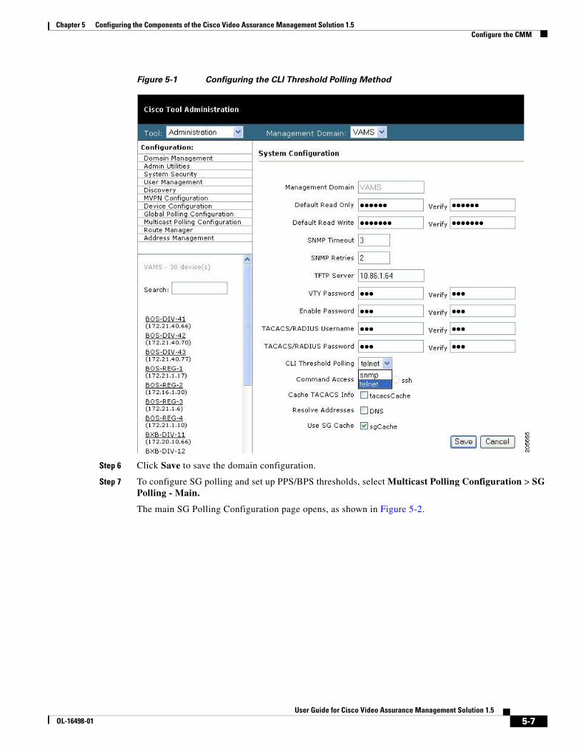
Chapter 5 Configuring the Components of the Cisco Video Assurance Management Solution 1.5 Configure the CMM
Figure 5-1 Configuring the CLI Threshold Polling Method
Step 6 Click Save to save the domain configuration.
Step 7 To configure SG polling and set up PPS/BPS thresholds, select Multicast Polling Configuration > SG Polling - Main.
The main SG Polling Configuration page opens, as shown in Figure 5-2.
5-7User Guide for Cisco Video Assurance Management Solution 1.5
OL-16498-01
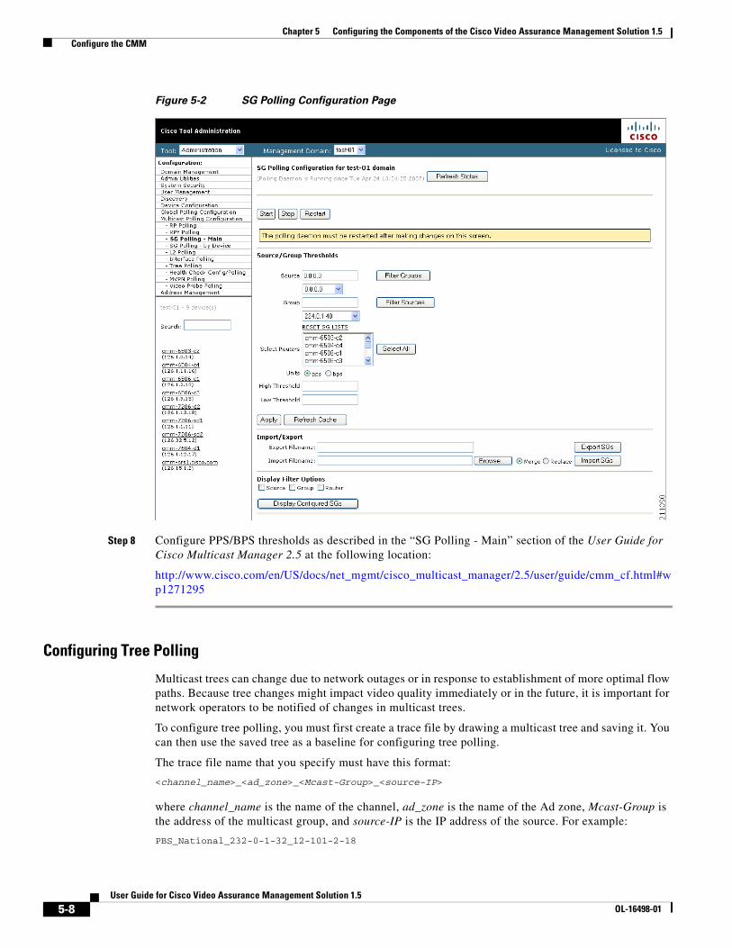
Chapter 5 Configuring the Components of the Cisco Video Assurance Management Solution 1.5 Configure the CMM
Figure 5-2 SG Polling Configuration Page
Step 8 Configure PPS/BPS thresholds as described in the “SG Polling - Main” section of the User Guide for Cisco Multicast Manager 2.5 at the following location:
http://www.cisco.com/en/US/docs/net_mgmt/cisco_multicast_manager/2.5/user/guide/cmm_cf.html#wp1271295
Configuring Tree Polling
Multicast trees can change due to network outages or in response to establishment of more optimal flow paths. Because tree changes might impact video quality immediately or in the future, it is important for network operators to be notified of changes in multicast trees.
To configure tree polling, you must first create a trace file by drawing a multicast tree and saving it. You can then use the saved tree as a baseline for configuring tree polling.
The trace file name that you specify must have this format:
<channel_name>_<ad_zone>_<Mcast-Group>_<source-IP>
where channel_name is the name of the channel, ad_zone is the name of the Ad zone, Mcast-Group is the address of the multicast group, and source-IP is the IP address of the source. For example:
PBS_National_232-0-1-32_12-101-2-18
5-8User Guide for Cisco Video Assurance Management Solution 1.5
OL-16498-01
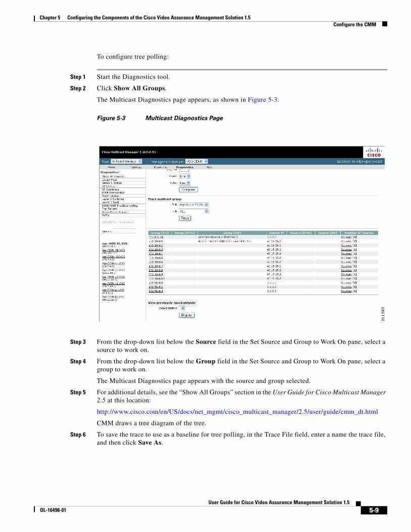
Chapter 5 Configuring the Components of the Cisco Video Assurance Management Solution 1.5 Configure the CMM
To configure tree polling:
Step 1 Start the Diagnostics tool.
Step 2 Click Show All Groups.
The Multicast Diagnostics page appears, as shown in Figure 5-3.
Figure 5-3 Multicast Diagnostics Page
Step 3 From the drop-down list below the Source field in the Set Source and Group to Work On pane, select a source to work on.
Step 4 From the drop-down list below the Group field in the Set Source and Group to Work On pane, select a group to work on.
The Multicast Diagnostics page appears with the source and group selected.
Step 5 For additional details, see the “Show All Groups” section in the User Guide for Cisco Multicast Manager 2.5 at this location:
http://www.cisco.com/en/US/docs/net_mgmt/cisco_multicast_manager/2.5/user/guide/cmm_dt.html
CMM draws a tree diagram of the tree.
Step 6 To save the trace to use as a baseline for tree polling, in the Trace File field, enter a name the trace file, and then click Save As.
5-9User Guide for Cisco Video Assurance Management Solution 1.5
OL-16498-01
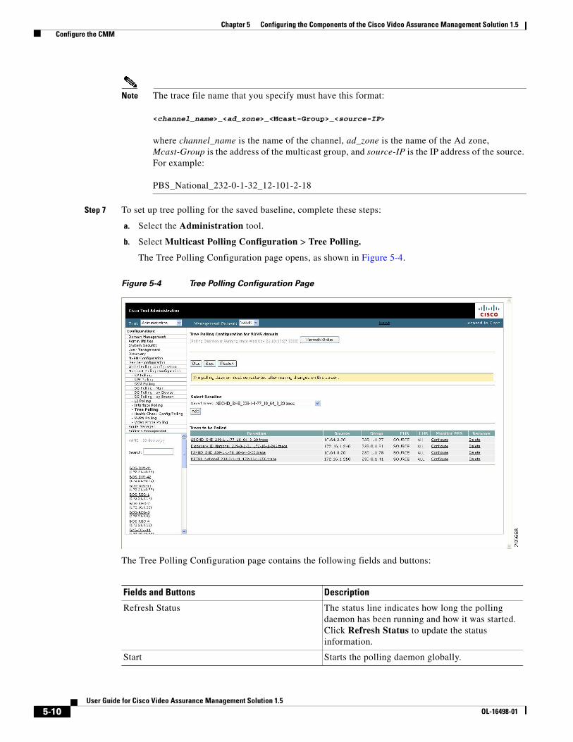
Chapter 5 Configuring the Components of the Cisco Video Assurance Management Solution 1.5 Configure the CMM
Note The trace file name that you specify must have this format: <channel_name>_<ad_zone>_<Mcast-Group>_<source-IP> where channel_name is the name of the channel, ad_zone is the name of the Ad zone, Mcast-Group is the address of the multicast group, and source-IP is the IP address of the source. For example: PBS_National_232-0-1-32_12-101-2-18
Step 7 To set up tree polling for the saved baseline, complete these steps:
a. Select the Administration tool.
b. Select Multicast Polling Configuration > Tree Polling.
The Tree Polling Configuration page opens, as shown in Figure 5-4.
Figure 5-4 Tree Polling Configuration Page
The Tree Polling Configuration page contains the following fields and buttons:
Fields and Buttons Description
Refresh Status The status line indicates how long the polling daemon has been running and how it was started. Click Refresh Status to update the status information.
Start Starts the polling daemon globally.
5-10User Guide for Cisco Video Assurance Management Solution 1.5
OL-16498-01
Chapter 5 Configuring the Components of the Cisco Video Assurance Management Solution 1.5 Configure the CMM
c. To monitor a tree, from the drop-down menu in the Saved Trees field, select the tree name, and click Add.
d. To specify how often the tree is polled:
– Click Global Polling Configuration.
The Global Polling Configuration Page appears.
– Click Tree Polling Interval, and on the dialog that appears, specify the time interval for tree polling.
– Save your changes.
– Click Set to save your global polling configuration.
The tree is drawn in the background for every interval that you set up for tree polling. This tree is compared with the tree saved in the database. If it is different, a trap is sent, and a report is generated.
Configuring Health Checks
The CMM application provides the ability to set up health checks that check and report on the status of critical components of your IP multicast network. Health checks can check the status of RPs, MSDP peering, the presence of sources and groups, and the status of multicast trees.
You should create a health check for every important source and group in your multicast network.
To configure health check polling:
Step 1 Select the Administration tool.
Step 2 Select Multicast Polling Configuration > Health Check Config/Polling.
Stop Stops the polling daemon globally.
Restart Restarts the polling daemon globally. Each time you change a polling interval, click Restart.
Saved Trees Lists all the multicast tree baselines that have been saved.
Add Adds the selected tree for monitoring.
Fields and Buttons Description
5-11User Guide for Cisco Video Assurance Management Solution 1.5
OL-16498-01
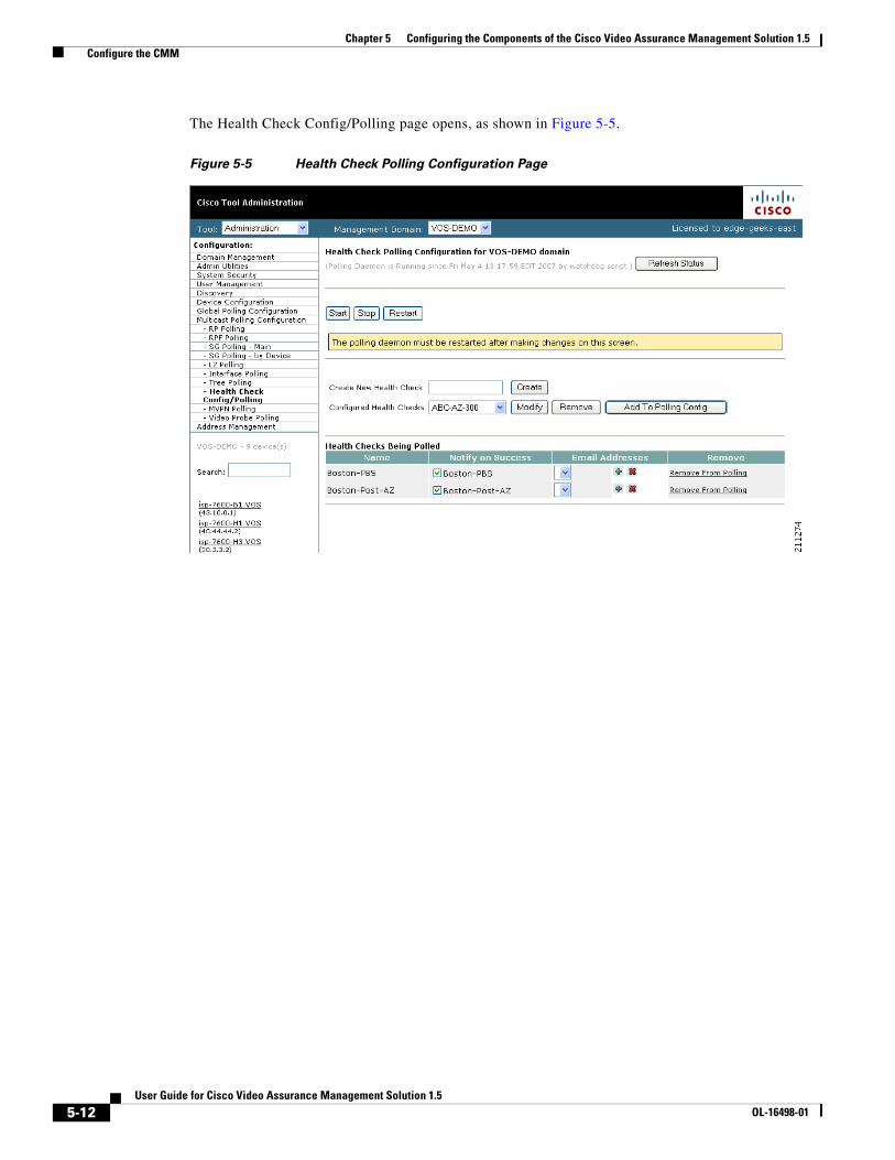
Chapter 5 Configuring the Components of the Cisco Video Assurance Management Solution 1.5 Configure the CMM
The Health Check Config/Polling page opens, as shown in Figure 5-5.
Figure 5-5 Health Check Polling Configuration Page
5-12User Guide for Cisco Video Assurance Management Solution 1.5
OL-16498-01
Chapter 5 Configuring the Components of the Cisco Video Assurance Management Solution 1.5 Configure the CMM
The Health Check Config/Polling page contains the following fields and buttons:
Configuring IP Multicast Heartbeat Monitoring
The CMM application can monitor the heartbeat of the routers that are forwarding a video flow. This is useful to confirm that the traffic stream is active.
To set up heartbeat monitoring requires that a downstream router or host has joined a multicast group or a static IGMP has been set; a data path must be established through the router that is configured for heartbeat monitoring.
Configuring heartbeat monitoring consists of two steps:
1. Configuring IP multicast on a router.
2. Enabling monitoring for the router.
Configuring IP Multicast Heartbeat on the Router
To configure IP multicast heartbeat on a router for which you want to enable IP multicast heartbeat, enter the following commands:
snmp-server enable traps ipmulticastip multicast heartbeat <ip_address> <minimum_number> <intervals> <interval_length>
where ip_address is the IP address of the router, minimum_number is the minimum number of intervals, intervals is the number of intervals, and interval_length is the length of the intervals in seconds.
The following is an example configuration of the ip multicast heartbeat command:
snmp-server enable traps ipmulticast-heartbeatip multicast heartbeat 224.0.1.53 1 1 10
Fields and Buttons Description
Create New Health Check Type a name for the health check.
Create Creates the new health check.
Configured Health Checks Select the health check you want to modify.
Modify To update a health check, select a health check from the drop-down list of health checks in the Configured Health checks field and then click Modify. A summary of the currently configured health checks appears.
Remove Removes the existing health check.
Add To Polling Config Schedules this health check to run automatically.
Name Name of the health check.
Notify on Success Generates an email report if the health check completes successfully.
Email Addresses Enter the email addresses to be notified. Click + to add an email address. Click - to remove an email address.
Remove Click Remove From Polling to stop the health check from running at scheduled intervals.
5-13User Guide for Cisco Video Assurance Management Solution 1.5
OL-16498-01
Chapter 5 Configuring the Components of the Cisco Video Assurance Management Solution 1.5 Configure Video Probes
Enabling Monitoring for the Router
To enable CMM monitoring for the router heartbeat, complete these steps to set the multicast group to monitor and specify the minimum number of packets that the router must process in an interval:
Step 1 Select Multicast Polling Configuration > SG Polling - Main.
The main SG Polling Configuration page opens.
Step 2 In the Group field, enter the IP address for the group to monitor.
Step 3 In the Select Routers list, select the router that you want to monitor.
Step 4 Scroll down to the bottom of the SG Polling configuration page and click Time-based thresholds (in the Time Threshold column).
Step 5 Set the number of intervals to monitor and the length of the intervals in seconds.
Step 6 Click the Set Thresholds button to save your changes.
Step 7 On the SG Polling Configuration page, click Apply.
Configure Video ProbesEach video probe in Cisco VAMS 1.5 monitors various parameters of the video flow through the network. For example, you might configure a video probe to monitor the amount of jitter or delay in a video stream.
For each video probe deployed in the network, you must configure the thresholds for the conditions that you want to monitor. You must also configure the video probes to forward traps to CIC. (Refer to the probe documentation for information on adding the CIC IP addresses and related SNMP information to the video probe settings.)
Once you configure the video probe, if a monitored condition exceeds a configured threshold, the probe sends a corresponding trap to CIC, which shows the event in the TBSM GUI and the Webtop GUI.
Note CMM 2.5.4 will poll the IneoQuest probes even though the probes may also be sending traps to the Cisco ANA.
Bridge Technologies Video ProbeTo configure the Bridge Technologies video probe for operation in the video transport network, refer to the documentation that comes with the product. These documents assist the network planner when integrating the Bridge Technologies video probes with the Cisco VAMS 1.5:
VB120 Broadcast IP-Probe User’s Manual v. 4.0
IneoQuest Video ProbeTo configure the IneoQuest video probe for operation in the video transport network, refer to the documentation that comes with the product. These documents assist the network planner when integrating the IneoQuest video probes with the Cisco VAMS 1.5:
5-14User Guide for Cisco Video Assurance Management Solution 1.5
OL-16498-01
Chapter 5 Configuring the Components of the Cisco Video Assurance Management Solution 1.5 Run the Setup for IPTV Script
• Hardware User’s Guide
• IQMediaAnalyzer Application User’s Guide
Mixed Signals Video ProbeTo configure the Mixed Signals video probe for operation in the video transport network, refer to the documentation that comes with the product. These documents assist the network planner when integrating the Mixed Signals video probes with the Cisco VAMS 1.5:
The Mixed Signals Sentry Digital Content Monitor User Guide
PixelMetrix Video ProbeTo configure the PixelMetrix video probe for operation in the video transport network, refer to the documentation that comes with the product. These documents assist the network planner when integrating the PixelMetrix video probes with the Cisco VAMS 1.5:
DVStation-IP-3 User Manual, Software Version 4.17
Tektronix Video ProbeTo configure the Tektronix video probe for operation in the video transport network, refer to the documentation that comes with the product. These documents assist the network planner when integrating the Tektronix video probes with the Cisco VAMS 1.5.
• MTM400 MPEG Transport Stream Monitor User Manual
• MTM400 MPEG Transport Stream Monitor Technical Reference
• MTM400 MPEG Transport Stream Monitor Programmer Manual
Run the Setup for IPTV ScriptThe Setup for IPTV activation script sets up network configuration parameters for the Cisco devices in the Cisco VAMS 1.5.
The script runs:
• ANA startup.
• Every two hours.
• Whenever the managed device reloads.
• When you activate it in ANA NetworkVision (see procedure).
The hourly run checks the IPTV configuration of the managed VNEs. If a VNE does not have the expected IPTV configuration, the script applies the IPTV configuration parameters to the device.
Note Configure the supported devices and load them with IPTV-enabled IOS images. The IPTV script does not recognize the devices without IPTV-enabled IOS images. (See the “Before You Install” section on page 3-1.)
5-15User Guide for Cisco Video Assurance Management Solution 1.5
OL-16498-01
Chapter 5 Configuring the Components of the Cisco Video Assurance Management Solution 1.5 Run the Cleanup from IPTV Script
To manually run the IPTV activation script for setup:
Step 1 Log in to ANA NetworkVision.
Step 2 Right-click a VNE in the network map.
Step 3 In the right-click menu, choose Management > Setup for IPTV.
Step 4 In the Setup for IPTV window, click the Execute button.
The result of the script appears in the same window under the Result tab.
Note If the selected VNE already has its IPTV configuration, the result indicates ALREADY CREATED, and the script does not run.
Run the Cleanup from IPTV ScriptYou run the Cleanup from IPTV activation script when you want to remove the IPTV extensions from a VNE that is in the Cisco VAMS 1.5. When you remove the extensions, the VNE will not be able to process the IPTV requests.
To run the Cleanup from IPTV script:
Step 1 Log in to ANA NetworkVision.
Step 2 Right-click the VNE in the network map.
Step 3 In the right-click menu, choose Management > Cleanup from IPTV.
The Cleanup from IPTV script runs and removes the IPTV extensions from the selected VNE.
CIC ConfigurationThe CIC configuration includes:
• Prerequisites, page 5-16
• Installation of Cisco ANA to Netcool Adapter, page 5-17
• Installing the IBM Tivoli Netcool Rules Files, page 5-19
• Installing IBM Tivoli Netcool View For ANA, page 5-21
• Configuring of Channel Mapping databases
• Configuration of the VAMS Cross-Launch menu
PrerequisitesVerify that the following patches are in Cisco ANA 3.6 Service Pack 1:
5-16User Guide for Cisco Video Assurance Management Solution 1.5
OL-16498-01
Chapter 5 Configuring the Components of the Cisco Video Assurance Management Solution 1.5 CIC Configuration
• CSCsj08845—Gateway sends duplicate alarms to the Netcool server.
• CSCsj16298—ANA2CIC—alarm notification sent to the drool misses properties.
Note Back up existing post.drl file, under the main/data directory. If the directory contains a new drools rules1 file, merge them with the post.drl file that will be added to the directory once the next step is complete.
Installation of Cisco ANA to Netcool AdapterTo install the Cisco ANA to the Netcool Adapter:
Step 1 Go to the release site and FTP the ps-Netcool-adapter-1.1-src.zip file:
http://wwwin-nmbu.cisco.com/Patches/patch-publisher/listbyproduct.cfm?searchbug=CSCsk84768 to the /export/home/sheer4 directory
Step 2 Unzip the file under the /export/home/sheer4 directory.
Note This procedure will override any existing post.drl files.
Step 3 Back up.
Step 4 If you are installing an AVM80 on the ANA gateway, skip this step.
To install the avm80.xml file on an ANA unit:
Copy the avm80.xml from directory ~Main/ registry/ConfigurationFiles/127.0.0.1 to an appropriate directory:
cp SHEERHOME/Main/registry/ConfigurationFiles/127.0.0.1/avm80.xml $SHEERHOME/Main/ registry/ConfigurationFiles/<unit_IP>
Step 5 In the drool installation, the JAR file contains the post.drl file. After unzipping and extracting the file, the file will override the existing data/post.drl file.
All relevant rules should have a condition tag set to true as follows:
java:condition>true</java:condition>
Set the following rules to true:
• sendAlarmNotification: Handles alarm and ticket notifications.
• sendAlarmNotificationOnProvisioningEvents: Handles provisioning events.
Step 6 Change the IP address 0.0.0.0 to the unit IP address if installed on the Cisco ANA unit. Then, run the following ANA gateway commands:
./runRegTool.sh -gs 127.0.0.1 add 0.0.0.0 avm99/services/bsm/avm80
./runRegTool.sh -gs 127.0.0.1 set 0.0.0.0 avm99/services/bsm/avm80/maxmem 512
./runRegTool.sh -gs 127.0.0.1 set 0.0.0.0 avm99/services/bsm/avm80/id 80
./runRegTool.sh -gs 127.0.0.1 set 0.0.0.0 avm99/services/bsm/avm80/enable false
./runRegTool.sh -gs 127.0.0.1 set 0.0.0.0 avm99/services/bsm/avm80/reqavm 0
./runRegTool.sh -gs 127.0.0.1 set 0.0.0.0 avm99/services/bsm/avm80/classesjar "classes.jar:ANA-Netcool-Adapter-1.1.jar"
Step 7 Verify that AVM80 has been updated correctly. If it has not, repeat the process.1. For a detailed definition, see the Glossary.
5-17User Guide for Cisco Video Assurance Management Solution 1.5
OL-16498-01
Chapter 5 Configuring the Components of the Cisco Video Assurance Management Solution 1.5 Log Level Configuration
Step 8 Edit the avm80.xml file containing the correct destination IP address and port number.
On the ANA gateway:
./runRegTool.sh -gs 127.0.0.1 set 127.0.0.1 avm80/services/trap-forwarder/destination-list/<Destination IP> 162
On the ANA unit:
./runRegTool.sh -gs 127.0.0.1 set <Unit_IP> avm80/services/trap-forwarder/destination-list/<Destination IP> 162
Step 9 To change the AVM80 trap type for the ANA gateway, run one of the following commands:
./runRegTool.sh -gs 127.0.0.1 set 127.0.0.1 avm80/services/trap-forwarder/snmp-version v1
./runRegTool.sh -gs 127.0.0.1 set 127.0.0.1 avm80/services/trap-forwarder/snmp-version v2
To change the AVM80 trap type for the ANA unit, run one of the following commands:
./runRegTool.sh -gs 127.0.0.1 set <Unit_IP> avm80/services/trap-forwarder/snmp-version v1
./runRegTool.sh -gs 127.0.0.1 set <Unit_IP> avm80/services/trap-forwarder/snmp-version v2
Step 10 From the ~/Main directory, run the mvm command.
~/Main]% ./mvm.csh
Step 11 Open the ANA Manage application and start the AVM80.
Log Level ConfigurationTo configure the log level for log monitoring:
Step 1 Run the following ANA gateway commands from the ~/Main directory:
Note Replace the IP address 127.0.0.1 with the ANA unit server IP address if the AVM80 does not reside in the Cisco ANA gateway.
./runRegTool.sh -gs 127.0.0.1 set 127.0.0.1 avm80/services/logger/log4j.category.com.cisco.integrations.cic DEBUG
./runRegTool.sh -gs 127.0.0.1 set 127.0.0.1 avm80/services/logger/log4j.category.Netcool-adapter DEBUG
Step 2 Use Cisco ANA Manage to stop and start the AVM80.
Step 3 To change the log level for log monitoring:
a. Go to the machine where the AVM80 is running.
b. Log in as user sheer.
c. Telnet to 0 2080.
d. Change the directory to logger.
e. Change the log level to DEBUG/ERROR/FATAL.
5-18User Guide for Cisco Video Assurance Management Solution 1.5
OL-16498-01
Chapter 5 Configuring the Components of the Cisco Video Assurance Management Solution 1.5 Installing the IBM Tivoli Netcool Rules Files
After changing the previous value to the desired level, the logs will appear in the 80.out directory.
Installing the IBM Tivoli Netcool Rules FilesConfigure the IBM Tivoli Netcool with a specific rules file created to identify the information that the Cisco ANA sends.
To install the IBM Tivoli Netcool rules files:
Step 1 First FTP the NCKL-1.2.3-CFM.tar.gz file to Netcool server.
Step 2 Put it in the directory $OMNIHOME/probes/linux2x86.
Step 3 Unzip the file:
gunzip NCKL-1.2.3-CFM.tar.gz
Step 4 Untar the file:
tar -vxf NCKL-1.2.3-CFM.tar
This should create a new directory called rules in the $OMNIHOME/probes/linux2x86 directory.
Step 5 Edit the .cshrc file as root and add the following environment variable at the end of the file after all the environment variables:
$NC_RULES_HOME=$OMNIHOME/probes/linux2x86/rules
Note Be sure to use the correct path.
Step 6 Exit the session and open a new session as root.
Step 7 FTP the Cisco EPM rules files to the $NC_RULES_HOME/include-snmptrap directory.
The rule files names are:
• cisco-CISCO-EPM-NOTIFICATION-MIB.adv.include.snmptrap.rules
• cisco-CISCO-EPM-NOTIFICATION-MIB.include.snmptrap.lookup
• cisco-CISCO-EPM-NOTIFICATION-MIB.include.snmptrap.rules
• cisco-CISCO-EPM-NOTIFICATION-MIB.sev.snmptrap.lookup
Step 8 FTP the ANA-New Probe.txt file from the caveat CSCsk84768 to the $NC_RULES_HOME/include-snmptrap directory and rename it by replacing the original cisco-EPM file:
mv ANA-New Probe.txt cisco-CISCO-EPM-NOTIFICATION-MIB.include.snmptrap.rules
Step 9 Edit the snmptrap.rules file located in directory $OMNIHOME/probes/linux2x86/rules to contain the following new lines:
Lookup files
a. include:
"$NC_RULES_HOME/include-snmptrap/cisco-CISCO-EPM-NOTIFICATION-MIB.include.snmptrap.lookup"
5-19User Guide for Cisco Video Assurance Management Solution 1.5
OL-16498-01
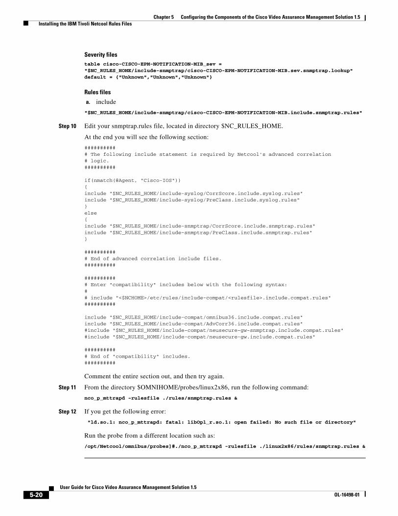
Chapter 5 Configuring the Components of the Cisco Video Assurance Management Solution 1.5 Installing the IBM Tivoli Netcool Rules Files
Severity filestable cisco-CISCO-EPM-NOTIFICATION-MIB_sev = "$NC_RULES_HOME/include-snmptrap/cisco-CISCO-EPM-NOTIFICATION-MIB.sev.snmptrap.lookup"default = {"Unknown","Unknown","Unknown"}
Rules files
a. include
"$NC_RULES_HOME/include-snmptrap/cisco-CISCO-EPM-NOTIFICATION-MIB.include.snmptrap.rules"
Step 10 Edit your snmptrap.rules file, located in directory $NC_RULES_HOME.
At the end you will see the following section:
########### The following include statement is required by Netcool's advanced correlation# logic.##########
if(nmatch(@Agent, "Cisco-IOS")){include "$NC_RULES_HOME/include-syslog/CorrScore.include.syslog.rules"include "$NC_RULES_HOME/include-syslog/PreClass.include.syslog.rules"}else{include "$NC_RULES_HOME/include-snmptrap/CorrScore.include.snmptrap.rules"include "$NC_RULES_HOME/include-snmptrap/PreClass.include.snmptrap.rules"}
########### End of advanced correlation include files.##########
########### Enter "compatibility" includes below with the following syntax:## include "<$NCHOME>/etc/rules/include-compat/<rulesfile>.include.compat.rules"##########
include "$NC_RULES_HOME/include-compat/omnibus36.include.compat.rules"include "$NC_RULES_HOME/include-compat/AdvCorr36.include.compat.rules"#include "$NC_RULES_HOME/include-compat/neusecure-gw-snmptrap.include.compat.rules"#include "$NC_RULES_HOME/include-compat/neusecure-gw.include.compat.rules"
########### End of "compatibility" includes.##########
Comment the entire section out, and then try again.
Step 11 From the directory $OMNIHOME/probes/linux2x86, run the following command:
nco_p_mttrapd -rulesfile ./rules/snmptrap.rules &
Step 12 If you get the following error:
"ld.so.1: nco_p_mttrapd: fatal: libOpl_r.so.1: open failed: No such file or directory"
Run the probe from a different location such as:
/opt/Netcool/omnibus/probes]#./nco_p_mttrapd -rulesfile ./linux2x86/rules/snmptrap.rules &
5-20User Guide for Cisco Video Assurance Management Solution 1.5
OL-16498-01
Chapter 5 Configuring the Components of the Cisco Video Assurance Management Solution 1.5 Installing IBM Tivoli Netcool View For ANA
Installing IBM Tivoli Netcool View For ANATo install IBM Tivoli Netcool View for ANA:
Step 1 FTP the Cisco ANA AdapterView.elc file from caveat CSCsk84768 to the Netcool server.
Step 2 Put it in the $OMNIHOME/utils directory.
Step 3 Open Netcool View, choose File > Open.
Step 4 Browse and select the $OMNIHOME/utils/Cisco ANA.elc file.
5-21User Guide for Cisco Video Assurance Management Solution 1.5
OL-16498-01

Chapter 5 Configuring the Components of the Cisco Video Assurance Management Solution 1.5 Installing IBM Tivoli Netcool View For ANA
5-22User Guide for Cisco Video Assurance Management Solution 1.5
OL-16498-01
User Guide foOL-16498-01
C H A P T E R 6
Troubleshooting with the Cisco Video Assurance Management Solution 1.5Troubleshooting with the Cisco VAMS 1.5 involves the use of:
• Monitoring Service Trees and Events using IBM Tivoli TBSM
• Monitoring ANA and CMM events using Netcool/Webtop
• CMM for advanced troubleshooting.
• Cisco ANA for basic troubleshooting.
This chapter contains:
• Monitoring ANA, CMM, and Video Probe Events with TBSM, page 6-1
• Monitoring ANA, CMM, and Video Probe Events with Netcool/Webtop, page 6-4
• Advanced Troubleshooting with CMM and TBSM, page 6-6
• Monitoring and Troubleshooting in the Wireline Network, page 6-19
• Monitoring and Troubleshooting in the Cable Network, page 6-19
• Troubleshooting with Cisco ANA, page 6-20
Monitoring ANA, CMM, and Video Probe Events with TBSM
Step 1 Log in to IBM Tivoli Business and Services Manager (TBSM).
The main TBSM page appears, as shown in Figure 6-4.
The highest severity alarm status is shown in the Service Tree at the left of the page.
6-1r Cisco Video Assurance Management Solution 1.5
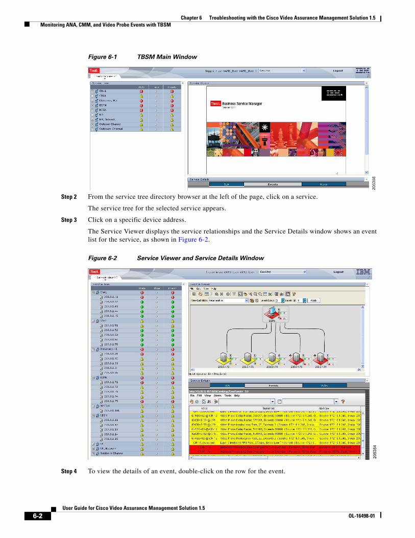
Chapter 6 Troubleshooting with the Cisco Video Assurance Management Solution 1.5 Monitoring ANA, CMM, and Video Probe Events with TBSM
Figure 6-1 TBSM Main Window
Step 2 From the service tree directory browser at the left of the page, click on a service.
The service tree for the selected service appears.
Step 3 Click on a specific device address.
The Service Viewer displays the service relationships and the Service Details window shows an event list for the service, as shown in Figure 6-2.
Figure 6-2 Service Viewer and Service Details Window
Step 4 To view the details of an event, double-click on the row for the event.
6-2User Guide for Cisco Video Assurance Management Solution 1.5
OL-16498-01
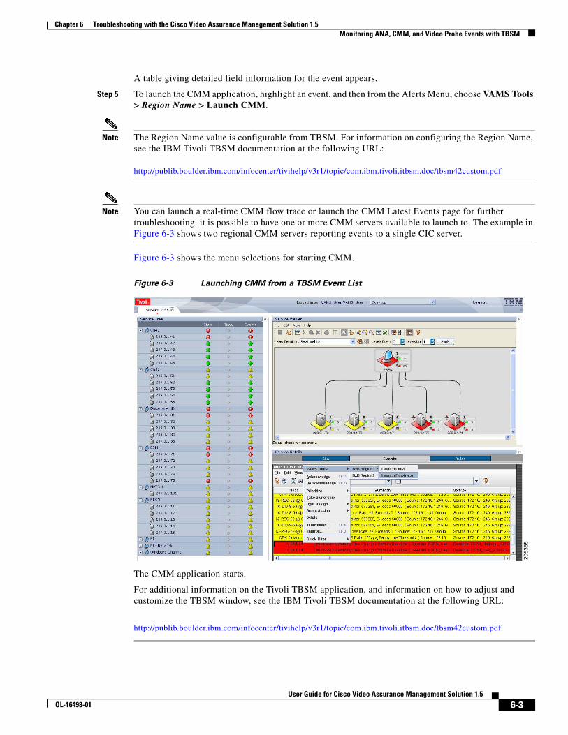
Chapter 6 Troubleshooting with the Cisco Video Assurance Management Solution 1.5 Monitoring ANA, CMM, and Video Probe Events with TBSM
A table giving detailed field information for the event appears.
Step 5 To launch the CMM application, highlight an event, and then from the Alerts Menu, choose VAMS Tools > Region Name > Launch CMM.
Note The Region Name value is configurable from TBSM. For information on configuring the Region Name, see the IBM Tivoli TBSM documentation at the following URL: http://publib.boulder.ibm.com/infocenter/tivihelp/v3r1/topic/com.ibm.tivoli.itbsm.doc/tbsm42custom.pdf
Note You can launch a real-time CMM flow trace or launch the CMM Latest Events page for further troubleshooting. it is possible to have one or more CMM servers available to launch to. The example in Figure 6-3 shows two regional CMM servers reporting events to a single CIC server.
Figure 6-3 shows the menu selections for starting CMM.
Figure 6-3 Launching CMM from a TBSM Event List
The CMM application starts.
For additional information on the Tivoli TBSM application, and information on how to adjust and customize the TBSM window, see the IBM Tivoli TBSM documentation at the following URL:
http://publib.boulder.ibm.com/infocenter/tivihelp/v3r1/topic/com.ibm.tivoli.itbsm.doc/tbsm42custom.pdf
6-3User Guide for Cisco Video Assurance Management Solution 1.5
OL-16498-01
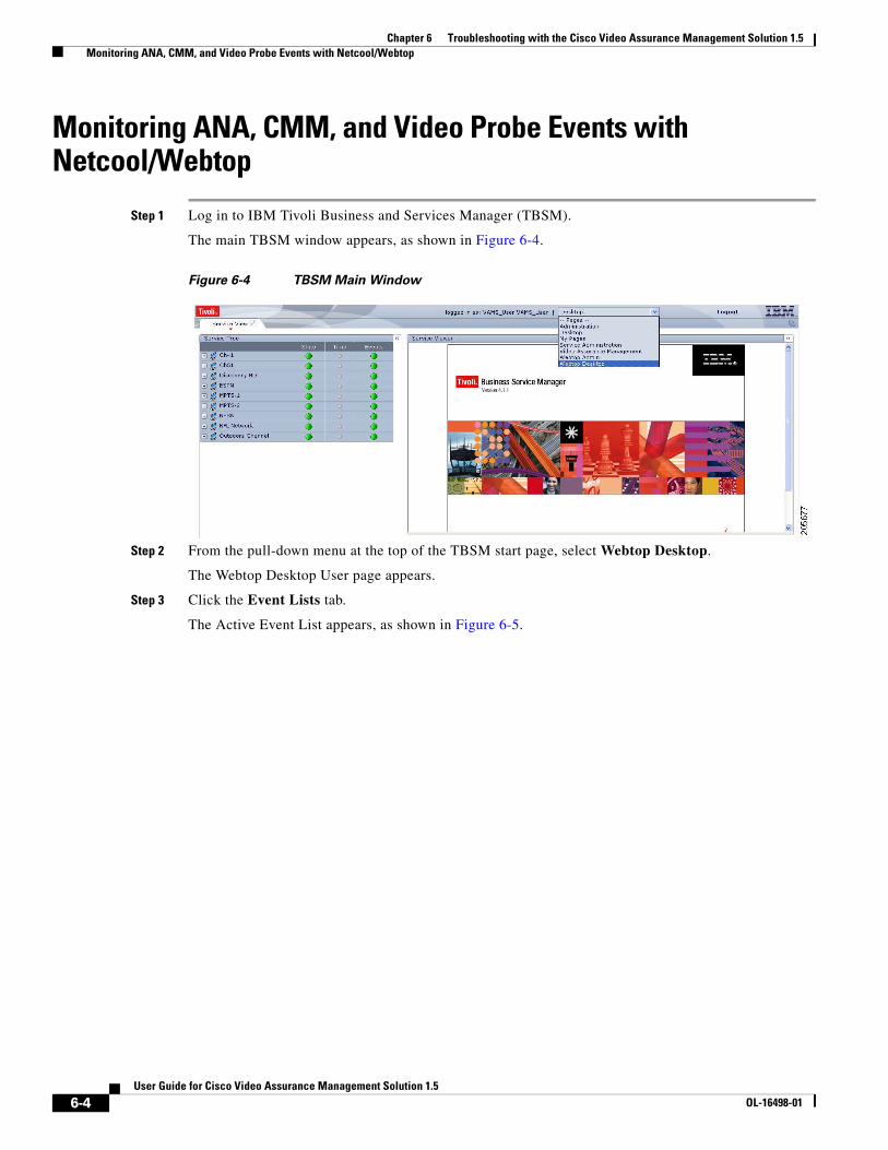
Chapter 6 Troubleshooting with the Cisco Video Assurance Management Solution 1.5 Monitoring ANA, CMM, and Video Probe Events with Netcool/Webtop
Monitoring ANA, CMM, and Video Probe Events with Netcool/Webtop
Step 1 Log in to IBM Tivoli Business and Services Manager (TBSM).
The main TBSM window appears, as shown in Figure 6-4.
Figure 6-4 TBSM Main Window
Step 2 From the pull-down menu at the top of the TBSM start page, select Webtop Desktop.
The Webtop Desktop User page appears.
Step 3 Click the Event Lists tab.
The Active Event List appears, as shown in Figure 6-5.
6-4User Guide for Cisco Video Assurance Management Solution 1.5
OL-16498-01
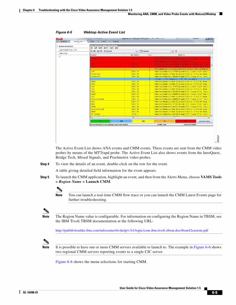
Chapter 6 Troubleshooting with the Cisco Video Assurance Management Solution 1.5 Monitoring ANA, CMM, and Video Probe Events with Netcool/Webtop
Figure 6-5 Webtop Active Event List
The Active Event List shows ANA events and CMM events. These events are sent from the CMM video probes by means of the MTTrapd probe. The Active Event List also shows events from the IneoQuest, Bridge Tech, Mixed Signals, and Pixelmetrix video probes.
Step 4 To view the details of an event, double-click on the row for the event.
A table giving detailed field information for the event appears.
Step 5 To launch the CMM application, highlight an event, and then from the Alerts Menu, choose VAMS Tools > Region Name > Launch CMM.
Note You can launch a real-time CMM flow trace or you can launch the CMM Latest Events page for further troubleshooting.
Note The Region Name value is configurable. For information on configuring the Region Name in TBSM, see the IBM Tivoli TBSM documentation at the following URL: http://publib.boulder.ibm.com/infocenter/tivihelp/v3r1/topic/com.ibm.tivoli.itbsm.doc/tbsm42custom.pdf
Note It is possible to have one or more CMM servers available to launch to. The example in Figure 6-6 shows two regional CMM servers reporting events to a single CIC server.
Figure 6-6 shows the menu selections for starting CMM.
6-5User Guide for Cisco Video Assurance Management Solution 1.5
OL-16498-01
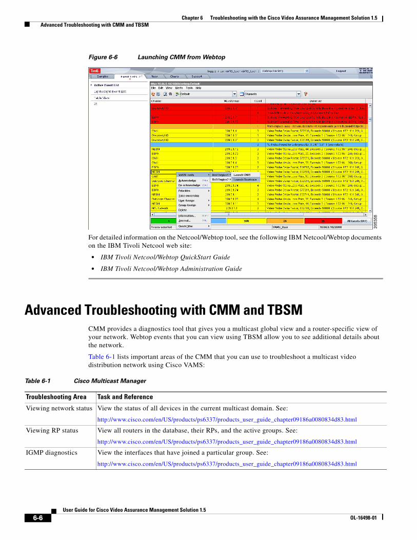
Chapter 6 Troubleshooting with the Cisco Video Assurance Management Solution 1.5 Advanced Troubleshooting with CMM and TBSM
Figure 6-6 Launching CMM from Webtop
For detailed information on the Netcool/Webtop tool, see the following IBM Netcool/Webtop documents on the IBM Tivoli Netcool web site:
• IBM Tivoli Netcool/Webtop QuickStart Guide
• IBM Tivoli Netcool/Webtop Administration Guide
Advanced Troubleshooting with CMM and TBSMCMM provides a diagnostics tool that gives you a multicast global view and a router-specific view of your network. Webtop events that you can view using TBSM allow you to see additional details about the network.
Table 6-1 lists important areas of the CMM that you can use to troubleshoot a multicast video distribution network using Cisco VAMS:
Table 6-1 Cisco Multicast Manager
Troubleshooting Area Task and Reference
Viewing network status View the status of all devices in the current multicast domain. See:
http://www.cisco.com/en/US/products/ps6337/products_user_guide_chapter09186a0080834d83.html
Viewing RP status View all routers in the database, their RPs, and the active groups. See:
http://www.cisco.com/en/US/products/ps6337/products_user_guide_chapter09186a0080834d83.html
IGMP diagnostics View the interfaces that have joined a particular group. See:
http://www.cisco.com/en/US/products/ps6337/products_user_guide_chapter09186a0080834d83.html
6-6User Guide for Cisco Video Assurance Management Solution 1.5
OL-16498-01
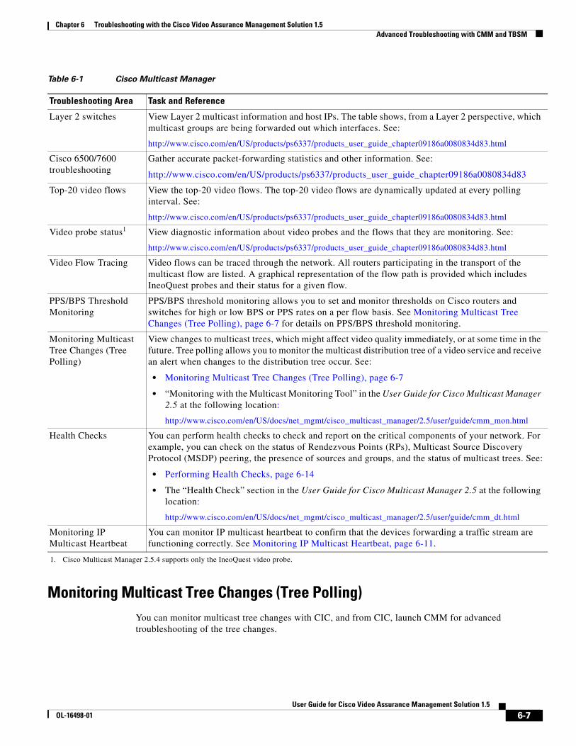
Chapter 6 Troubleshooting with the Cisco Video Assurance Management Solution 1.5 Advanced Troubleshooting with CMM and TBSM
Monitoring Multicast Tree Changes (Tree Polling)You can monitor multicast tree changes with CIC, and from CIC, launch CMM for advanced troubleshooting of the tree changes.
Layer 2 switches View Layer 2 multicast information and host IPs. The table shows, from a Layer 2 perspective, which multicast groups are being forwarded out which interfaces. See:
http://www.cisco.com/en/US/products/ps6337/products_user_guide_chapter09186a0080834d83.html
Cisco 6500/7600 troubleshooting
Gather accurate packet-forwarding statistics and other information. See:
http://www.cisco.com/en/US/products/ps6337/products_user_guide_chapter09186a0080834d83
Top-20 video flows View the top-20 video flows. The top-20 video flows are dynamically updated at every polling interval. See:
http://www.cisco.com/en/US/products/ps6337/products_user_guide_chapter09186a0080834d83.html
Video probe status1 View diagnostic information about video probes and the flows that they are monitoring. See:
http://www.cisco.com/en/US/products/ps6337/products_user_guide_chapter09186a0080834d83.html
Video Flow Tracing Video flows can be traced through the network. All routers participating in the transport of the multicast flow are listed. A graphical representation of the flow path is provided which includes IneoQuest probes and their status for a given flow.
PPS/BPS Threshold Monitoring
PPS/BPS threshold monitoring allows you to set and monitor thresholds on Cisco routers and switches for high or low BPS or PPS rates on a per flow basis. See Monitoring Multicast Tree Changes (Tree Polling), page 6-7 for details on PPS/BPS threshold monitoring.
Monitoring Multicast Tree Changes (Tree Polling)
View changes to multicast trees, which might affect video quality immediately, or at some time in the future. Tree polling allows you to monitor the multicast distribution tree of a video service and receive an alert when changes to the distribution tree occur. See:
• Monitoring Multicast Tree Changes (Tree Polling), page 6-7
• “Monitoring with the Multicast Monitoring Tool” in the User Guide for Cisco Multicast Manager 2.5 at the following location:
http://www.cisco.com/en/US/docs/net_mgmt/cisco_multicast_manager/2.5/user/guide/cmm_mon.html
Health Checks You can perform health checks to check and report on the critical components of your network. For example, you can check on the status of Rendezvous Points (RPs), Multicast Source Discovery Protocol (MSDP) peering, the presence of sources and groups, and the status of multicast trees. See:
• Performing Health Checks, page 6-14
• The “Health Check” section in the User Guide for Cisco Multicast Manager 2.5 at the following location:
http://www.cisco.com/en/US/docs/net_mgmt/cisco_multicast_manager/2.5/user/guide/cmm_dt.html
Monitoring IP Multicast Heartbeat
You can monitor IP multicast heartbeat to confirm that the devices forwarding a traffic stream are functioning correctly. See Monitoring IP Multicast Heartbeat, page 6-11.
1. Cisco Multicast Manager 2.5.4 supports only the IneoQuest video probe.
Table 6-1 Cisco Multicast Manager
Troubleshooting Area Task and Reference
6-7User Guide for Cisco Video Assurance Management Solution 1.5
OL-16498-01
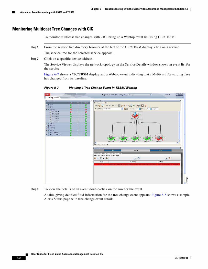
Chapter 6 Troubleshooting with the Cisco Video Assurance Management Solution 1.5 Advanced Troubleshooting with CMM and TBSM
Monitoring Multicast Tree Changes with CIC
To monitor multicast tree changes with CIC, bring up a Webtop event list using CIC/TBSM:
Step 1 From the service tree directory browser at the left of the CIC/TBSM display, click on a service.
The service tree for the selected service appears.
Step 2 Click on a specific device address.
The Service Viewer displays the network topology an the Service Details window shows an event list for the service.
Figure 6-7 shows a CIC/TBSM display and a Webtop event indicating that a Multicast Forwarding Tree has changed from its baseline.
Figure 6-7 Viewing a Tree Change Event in TBSM/Webtop
Step 3 To view the details of an event, double-click on the row for the event.
A table giving detailed field information for the tree change event appears. Figure 6-8 shows a sample Alerts Status page with tree change event details.
6-8User Guide for Cisco Video Assurance Management Solution 1.5
OL-16498-01
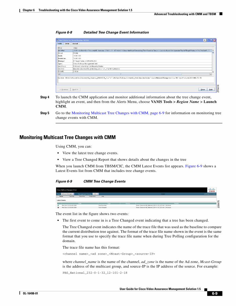
Chapter 6 Troubleshooting with the Cisco Video Assurance Management Solution 1.5 Advanced Troubleshooting with CMM and TBSM
Figure 6-8 Detailed Tree Change Event Information
Step 4 To launch the CMM application and monitor additional information about the tree change event, highlight an event, and then from the Alerts Menu, choose VAMS Tools > Region Name > Launch CMM.
Step 5 Go to the Monitoring Multicast Tree Changes with CMM, page 6-9 for information on monitoring tree change events with CMM.
Monitoring Multicast Tree Changes with CMM
Using CMM, you can:
• View the latest tree change events.
• View a Tree Changed Report that shows details about the changes in the tree
When you launch CMM from TBSM/CIC, the CMM Latest Events list appears. Figure 6-9 shows a Latest Events list from CMM that includes tree change events.
Figure 6-9 CMM Tree Change Events
The event list in the figure shows two events:
• The first event to come in is a Tree Changed event indicating that a tree has been changed.
The Tree Changed event indicates the name of the trace file that was used as the baseline to compare the current distribution tree against. The format of the trace file name shown in the event is the same format that you use to specify the trace file name when during Tree Polling configuration for the domain.
The trace file name has this format:
<channel name>_<ad zone>_<Mcast-Group>_<source-IP>
where channel_name is the name of the channel, ad_zone is the name of the Ad zone, Mcast-Group is the address of the multicast group, and source-IP is the IP address of the source. For example:
PBS_National_232-0-1-32_12-101-2-18
6-9User Guide for Cisco Video Assurance Management Solution 1.5
OL-16498-01
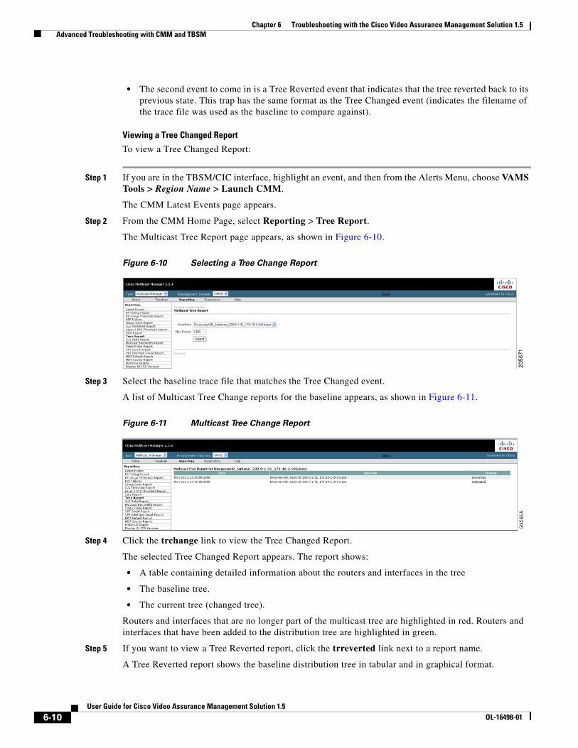
Chapter 6 Troubleshooting with the Cisco Video Assurance Management Solution 1.5 Advanced Troubleshooting with CMM and TBSM
• The second event to come in is a Tree Reverted event that indicates that the tree reverted back to its previous state. This trap has the same format as the Tree Changed event (indicates the filename of the trace file was used as the baseline to compare against).
Viewing a Tree Changed Report
To view a Tree Changed Report:
Step 1 If you are in the TBSM/CIC interface, highlight an event, and then from the Alerts Menu, choose VAMS Tools > Region Name > Launch CMM.
The CMM Latest Events page appears.
Step 2 From the CMM Home Page, select Reporting > Tree Report.
The Multicast Tree Report page appears, as shown in Figure 6-10.
Figure 6-10 Selecting a Tree Change Report
Step 3 Select the baseline trace file that matches the Tree Changed event.
A list of Multicast Tree Change reports for the baseline appears, as shown in Figure 6-11.
Figure 6-11 Multicast Tree Change Report
Step 4 Click the trchange link to view the Tree Changed Report.
The selected Tree Changed Report appears. The report shows:
• A table containing detailed information about the routers and interfaces in the tree
• The baseline tree.
• The current tree (changed tree).
Routers and interfaces that are no longer part of the multicast tree are highlighted in red. Routers and interfaces that have been added to the distribution tree are highlighted in green.
Step 5 If you want to view a Tree Reverted report, click the trreverted link next to a report name.
A Tree Reverted report shows the baseline distribution tree in tabular and in graphical format.
6-10User Guide for Cisco Video Assurance Management Solution 1.5
OL-16498-01
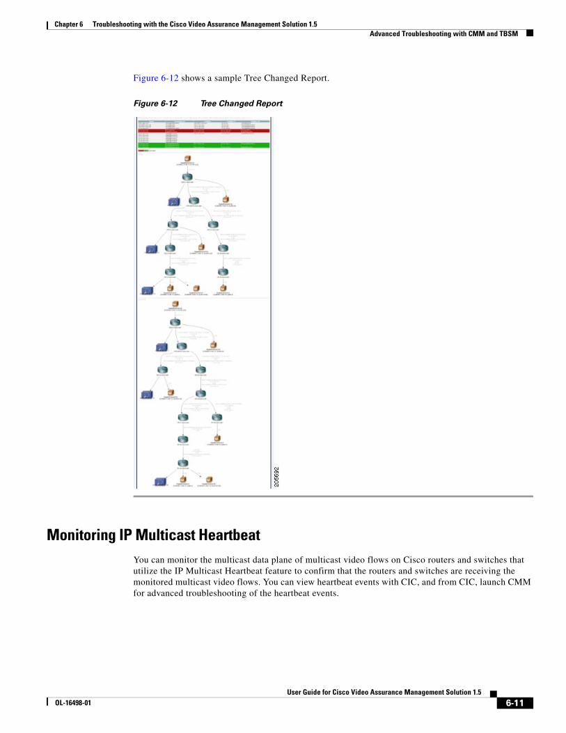
Chapter 6 Troubleshooting with the Cisco Video Assurance Management Solution 1.5 Advanced Troubleshooting with CMM and TBSM
Figure 6-12 shows a sample Tree Changed Report.
Figure 6-12 Tree Changed Report
Monitoring IP Multicast HeartbeatYou can monitor the multicast data plane of multicast video flows on Cisco routers and switches that utilize the IP Multicast Heartbeat feature to confirm that the routers and switches are receiving the monitored multicast video flows. You can view heartbeat events with CIC, and from CIC, launch CMM for advanced troubleshooting of the heartbeat events.
6-11User Guide for Cisco Video Assurance Management Solution 1.5
OL-16498-01

Chapter 6 Troubleshooting with the Cisco Video Assurance Management Solution 1.5 Advanced Troubleshooting with CMM and TBSM
Monitoring Heartbeat Events with CIC/TBSM
To view heartbeat events in TBSM/Webtop:
Step 1 From the service tree directory browser at the left of the TBSM display, click on a service.
The service tree for the selected service appears.
Step 2 Click on a specific device address.
The Service Viewer displays the network topology and the Service Details window shows an event list for the service.
Figure 6-13 shows a Webtop/TBSM display with a heartbeat event indicating that a a heartbeat threshold has been violated on a router.
Figure 6-13 Viewing a Heartbeat Event in TBSM/Webtop
The Summary column shows the IP address of the router that generated the heartbeat event.
Step 3 To view additional details about the event, double click on the event in the Webtop display.
Figure 6-14 shows a sample Alerts Status page with heartbeat event details.
6-12User Guide for Cisco Video Assurance Management Solution 1.5
OL-16498-01
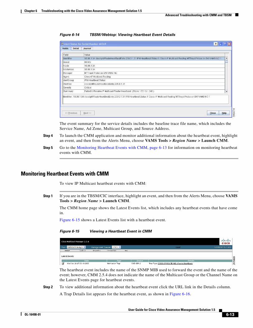
Chapter 6 Troubleshooting with the Cisco Video Assurance Management Solution 1.5 Advanced Troubleshooting with CMM and TBSM
Figure 6-14 TBSM/Webtop: Viewing Heartbeat Event Details
The event summary for the service details includes the baseline trace file name, which includes the Service Name, Ad Zone, Multicast Group, and Source Address.
Step 4 To launch the CMM application and monitor additional information about the heartbeat event, highlight an event, and then from the Alerts Menu, choose VAMS Tools > Region Name > Launch CMM.
Step 5 Go to the Monitoring Heartbeat Events with CMM, page 6-13 for information on monitoring heartbeat events with CMM.
Monitoring Heartbeat Events with CMM
To view IP Multicast heartbeat events with CMM:
Step 1 If you are in the TBSM/CIC interface, highlight an event, and then from the Alerts Menu, choose VAMS Tools > Region Name > Launch CMM.
The CMM home page shows the Latest Events list, which includes any heartbeat events that have come in.
Figure 6-15 shows a Latest Events list with a heartbeat event.
Figure 6-15 Viewing a Heartbeat Event in CMM
The heartbeat event includes the name of the SNMP MIB used to forward the event and the name of the event; however, CMM 2.5.4 does not indicate the name of the Multicast Group or the Channel Name on the Latest Events page for heartbeat events.
Step 2 To view additional information about the heartbeat event click the URL link in the Details column.
A Trap Details list appears for the heartbeat event, as shown in Figure 6-16.
6-13User Guide for Cisco Video Assurance Management Solution 1.5
OL-16498-01
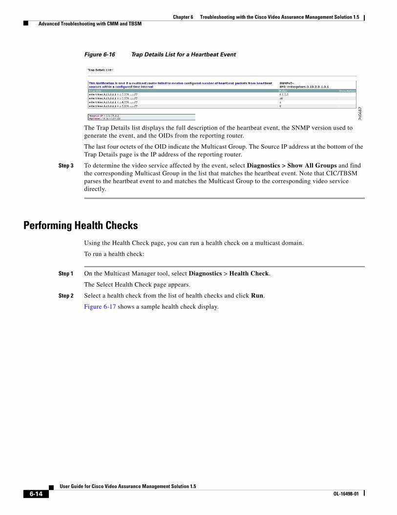
Chapter 6 Troubleshooting with the Cisco Video Assurance Management Solution 1.5 Advanced Troubleshooting with CMM and TBSM
Figure 6-16 Trap Details List for a Heartbeat Event
The Trap Details list displays the full description of the heartbeat event, the SNMP version used to generate the event, and the OIDs from the reporting router.
The last four octets of the OID indicate the Multicast Group. The Source IP address at the bottom of the Trap Details page is the IP address of the reporting router.
Step 3 To determine the video service affected by the event, select Diagnostics > Show All Groups and find the corresponding Multicast Group in the list that matches the heartbeat event. Note that CIC/TBSM parses the heartbeat event to and matches the Multicast Group to the corresponding video service directly.
Performing Health ChecksUsing the Health Check page, you can run a health check on a multicast domain.
To run a health check:
Step 1 On the Multicast Manager tool, select Diagnostics > Health Check.
The Select Health Check page appears.
Step 2 Select a health check from the list of health checks and click Run.
Figure 6-17 shows a sample health check display.
6-14User Guide for Cisco Video Assurance Management Solution 1.5
OL-16498-01
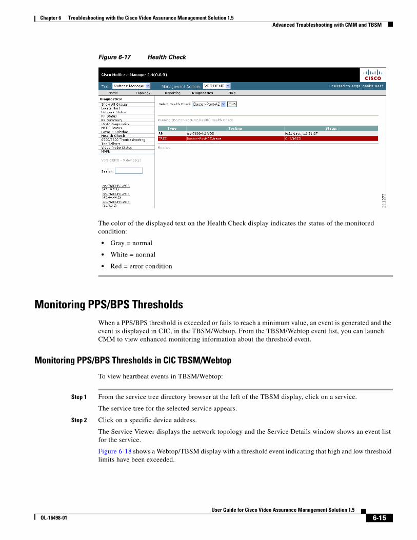
Chapter 6 Troubleshooting with the Cisco Video Assurance Management Solution 1.5 Advanced Troubleshooting with CMM and TBSM
Figure 6-17 Health Check
The color of the displayed text on the Health Check display indicates the status of the monitored condition:
• Gray = normal
• White = normal
• Red = error condition
Monitoring PPS/BPS ThresholdsWhen a PPS/BPS threshold is exceeded or fails to reach a minimum value, an event is generated and the event is displayed in CIC, in the TBSM/Webtop. From the TBSM/Webtop event list, you can launch CMM to view enhanced monitoring information about the threshold event.
Monitoring PPS/BPS Thresholds in CIC TBSM/Webtop
To view heartbeat events in TBSM/Webtop:
Step 1 From the service tree directory browser at the left of the TBSM display, click on a service.
The service tree for the selected service appears.
Step 2 Click on a specific device address.
The Service Viewer displays the network topology and the Service Details window shows an event list for the service.
Figure 6-18 shows a Webtop/TBSM display with a threshold event indicating that high and low threshold limits have been exceeded.
6-15User Guide for Cisco Video Assurance Management Solution 1.5
OL-16498-01
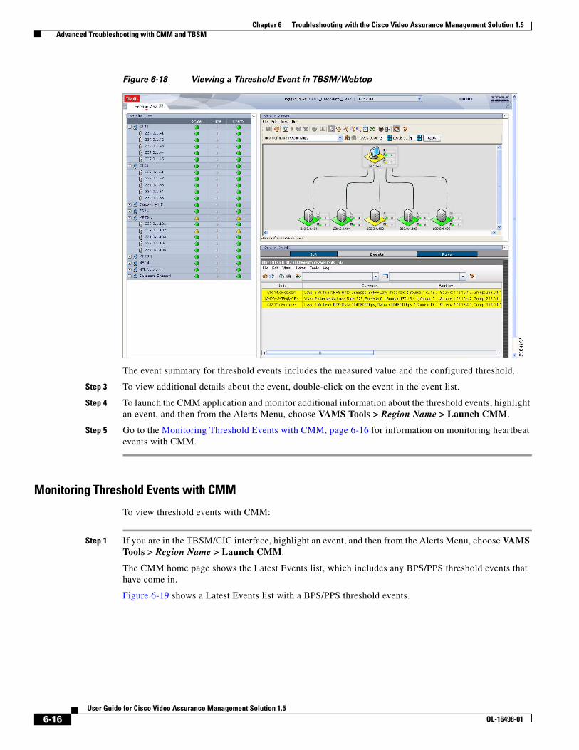
Chapter 6 Troubleshooting with the Cisco Video Assurance Management Solution 1.5 Advanced Troubleshooting with CMM and TBSM
Figure 6-18 Viewing a Threshold Event in TBSM/Webtop
The event summary for threshold events includes the measured value and the configured threshold.
Step 3 To view additional details about the event, double-click on the event in the event list.
Step 4 To launch the CMM application and monitor additional information about the threshold events, highlight an event, and then from the Alerts Menu, choose VAMS Tools > Region Name > Launch CMM.
Step 5 Go to the Monitoring Threshold Events with CMM, page 6-16 for information on monitoring heartbeat events with CMM.
Monitoring Threshold Events with CMM
To view threshold events with CMM:
Step 1 If you are in the TBSM/CIC interface, highlight an event, and then from the Alerts Menu, choose VAMS Tools > Region Name > Launch CMM.
The CMM home page shows the Latest Events list, which includes any BPS/PPS threshold events that have come in.
Figure 6-19 shows a Latest Events list with a BPS/PPS threshold events.
6-16User Guide for Cisco Video Assurance Management Solution 1.5
OL-16498-01
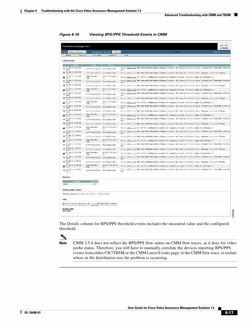
Chapter 6 Troubleshooting with the Cisco Video Assurance Management Solution 1.5 Advanced Troubleshooting with CMM and TBSM
Figure 6-19 Viewing BPS/PPS Threshold Events in CMM
The Details column for BPS/PPS threshold events includes the measured value and the configured threshold.
Note CMM 2.5.4 does not reflect the BPS/PPS flow status on CMM flow traces, as it does for video probe status. Therefore, you will have to manually correlate the devices reporting BPS/PPS events from either CIC/TBSM or the CMM Latest Events page, to the CMM flow trace, to isolate where in the distribution tree the problem is occurring.
6-17User Guide for Cisco Video Assurance Management Solution 1.5
OL-16498-01

Chapter 6 Troubleshooting with the Cisco Video Assurance Management Solution 1.5 Advanced Troubleshooting with CMM and TBSM
Running Threshold Reports
CMM provides two threshold reports that you can use to monitor threshold events:
• S, G Threshold Report—Shows threshold events for a specified source and group.
• Layer 2 PPS Threshold Report—Shows threshold events for a specified port on a specified switch.
To run an S, G Threshold report:
Step 1 In the CMM Multicast Manager tool, click Reporting.
Step 2 Select S, G Threshold Report.
A list of groups appears.
Step 3 Select a group from the list and then click Report.
CMM displays an S,G Threshold Report listing any events that have occurred in the last 24 hours.
To run a Layer 2 PPS Threshold report:
Step 1 In the CMM Multicast Manager tool, click Reporting.
Step 2 Select Layer 2 PPS Threshold Report.
A list of groups appears.
Step 3 Select a group from the list and then click Report.
CMM displays a Layer 2 PPS Threshold Report listing any events that have occurred in the last 24 hours.
6-18User Guide for Cisco Video Assurance Management Solution 1.5
OL-16498-01
Chapter 6 Troubleshooting with the Cisco Video Assurance Management Solution 1.5 Monitoring and Troubleshooting in the Wireline Network
Monitoring and Troubleshooting in the Wireline NetworkThe Cisco Wireline Video/IPTV Solution Design and Implementation Guide, Release 1.1, provides an introduction to monitoring and troubleshooting the Cisco Ethernet switches in the Cisco wireline-based IPTV solution. Troubleshooting areas include:
• Network Time Protocol (NTP)
• Syslog
• Quality of Service (QoS)
• Multicast
Monitoring and troubleshooting information is viewable online at:
http://www.cisco.com/en/US/products/ps6902/products_implementation_design_guide_ chapter09186a00806ac2e0.html
Monitoring and Troubleshooting in the Cable NetworkThe Cisco Gigabit-Ethernet Optimized Video Networking Solution for Cable Design and Implementation Guide, Release 3.0, provides an introduction to monitoring and troubleshooting the Cisco Ethernet switches in the Cisco cable-based IPTV solution. Troubleshooting areas include:
• Troubleshooting multicast.
• Show commands.
• Debug commands.
• Viewing hardware rate limiter (HWRL) counters.
Monitoring and troubleshooting information is viewable online at:
http://www.cisco.com/en/US/products/ps6902/products_implementation_design_guide _chapter09186a0080645ae0.html
6-19User Guide for Cisco Video Assurance Management Solution 1.5
OL-16498-01
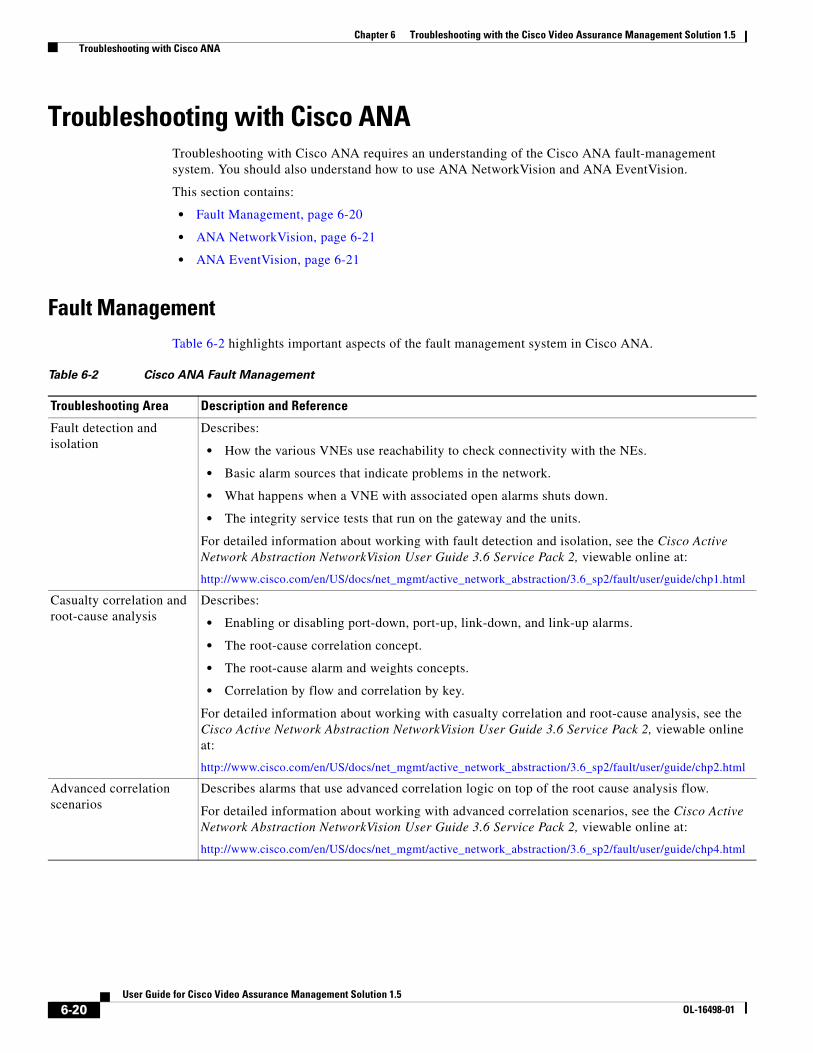
Chapter 6 Troubleshooting with the Cisco Video Assurance Management Solution 1.5 Troubleshooting with Cisco ANA
Troubleshooting with Cisco ANATroubleshooting with Cisco ANA requires an understanding of the Cisco ANA fault-management system. You should also understand how to use ANA NetworkVision and ANA EventVision.
This section contains:
• Fault Management, page 6-20
• ANA NetworkVision, page 6-21
• ANA EventVision, page 6-21
Fault ManagementTable 6-2 highlights important aspects of the fault management system in Cisco ANA.
Table 6-2 Cisco ANA Fault Management
Troubleshooting Area Description and Reference
Fault detection and isolation
Describes:
• How the various VNEs use reachability to check connectivity with the NEs.
• Basic alarm sources that indicate problems in the network.
• What happens when a VNE with associated open alarms shuts down.
• The integrity service tests that run on the gateway and the units.
For detailed information about working with fault detection and isolation, see the Cisco Active Network Abstraction NetworkVision User Guide 3.6 Service Pack 2, viewable online at:
http://www.cisco.com/en/US/docs/net_mgmt/active_network_abstraction/3.6_sp2/fault/user/guide/chp1.html
Casualty correlation and root-cause analysis
Describes:
• Enabling or disabling port-down, port-up, link-down, and link-up alarms.
• The root-cause correlation concept.
• The root-cause alarm and weights concepts.
• Correlation by flow and correlation by key.
For detailed information about working with casualty correlation and root-cause analysis, see the Cisco Active Network Abstraction NetworkVision User Guide 3.6 Service Pack 2, viewable online at:
http://www.cisco.com/en/US/docs/net_mgmt/active_network_abstraction/3.6_sp2/fault/user/guide/chp2.html
Advanced correlation scenarios
Describes alarms that use advanced correlation logic on top of the root cause analysis flow.
For detailed information about working with advanced correlation scenarios, see the Cisco Active Network Abstraction NetworkVision User Guide 3.6 Service Pack 2, viewable online at:
http://www.cisco.com/en/US/docs/net_mgmt/active_network_abstraction/3.6_sp2/fault/user/guide/chp4.html
6-20User Guide for Cisco Video Assurance Management Solution 1.5
OL-16498-01
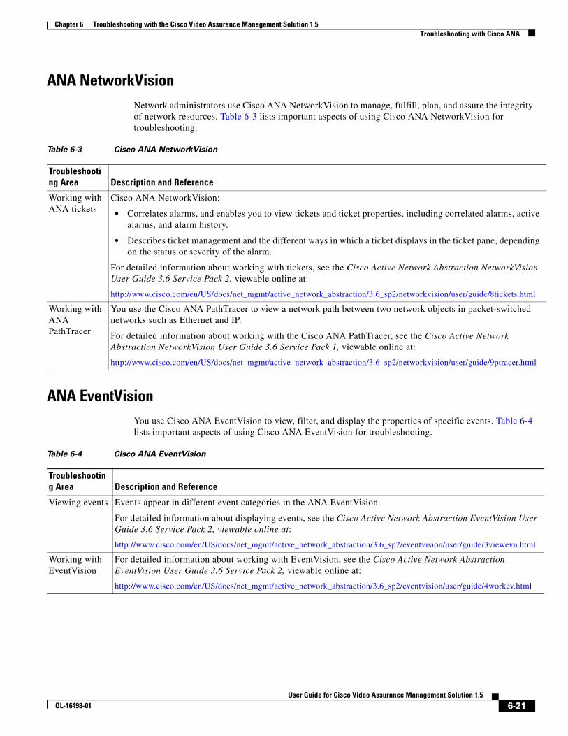
Chapter 6 Troubleshooting with the Cisco Video Assurance Management Solution 1.5 Troubleshooting with Cisco ANA
ANA NetworkVisionNetwork administrators use Cisco ANA NetworkVision to manage, fulfill, plan, and assure the integrity of network resources. Table 6-3 lists important aspects of using Cisco ANA NetworkVision for troubleshooting.
ANA EventVisionYou use Cisco ANA EventVision to view, filter, and display the properties of specific events. Table 6-4 lists important aspects of using Cisco ANA EventVision for troubleshooting.
Table 6-3 Cisco ANA NetworkVision
Troubleshooting Area Description and Reference
Working with ANA tickets
Cisco ANA NetworkVision:
• Correlates alarms, and enables you to view tickets and ticket properties, including correlated alarms, active alarms, and alarm history.
• Describes ticket management and the different ways in which a ticket displays in the ticket pane, depending on the status or severity of the alarm.
For detailed information about working with tickets, see the Cisco Active Network Abstraction NetworkVision User Guide 3.6 Service Pack 2, viewable online at:
http://www.cisco.com/en/US/docs/net_mgmt/active_network_abstraction/3.6_sp2/networkvision/user/guide/8tickets.html
Working with ANA PathTracer
You use the Cisco ANA PathTracer to view a network path between two network objects in packet-switched networks such as Ethernet and IP.
For detailed information about working with the Cisco ANA PathTracer, see the Cisco Active Network Abstraction NetworkVision User Guide 3.6 Service Pack 1, viewable online at:
http://www.cisco.com/en/US/docs/net_mgmt/active_network_abstraction/3.6_sp2/networkvision/user/guide/9ptracer.html
Table 6-4 Cisco ANA EventVision
Troubleshooting Area Description and Reference
Viewing events Events appear in different event categories in the ANA EventVision.
For detailed information about displaying events, see the Cisco Active Network Abstraction EventVision User Guide 3.6 Service Pack 2, viewable online at:
http://www.cisco.com/en/US/docs/net_mgmt/active_network_abstraction/3.6_sp2/eventvision/user/guide/3viewevn.html
Working with EventVision
For detailed information about working with EventVision, see the Cisco Active Network Abstraction EventVision User Guide 3.6 Service Pack 2, viewable online at:
http://www.cisco.com/en/US/docs/net_mgmt/active_network_abstraction/3.6_sp2/eventvision/user/guide/4workev.html
6-21User Guide for Cisco Video Assurance Management Solution 1.5
OL-16498-01

Chapter 6 Troubleshooting with the Cisco Video Assurance Management Solution 1.5 Troubleshooting with Cisco ANA
6-22User Guide for Cisco Video Assurance Management Solution 1.5
OL-16498-01
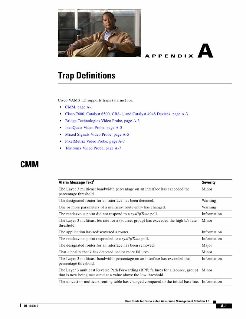
User Guide for CiscOL-16498-01
A
P P E N D I X A Trap DefinitionsCisco VAMS 1.5 supports traps (alarms) for:
• CMM, page A-1
• Cisco 7600, Catalyst 6500, CRS-1, and Catalyst 4948 Devices, page A-3
• Bridge Technologies Video Probe, page A-3
• IneoQuest Video Probe, page A-5
• Mixed Signals Video Probe, page A-5
• PixelMetrix Video Probe, page A-7
• Tektronix Video Probe, page A-7
CMM
Alarm Message Text1 Severity
The Layer 3 multicast bandwidth percentage on an interface has exceeded the percentage threshold.
Minor
The designated router for an interface has been detected. Warning
One or more parameters of a multicast route entry has changed. Warning
The rendezvous point did not respond to a sysUpTime poll. Information
The Layer 3 multicast b/s rate for a (source, group) has exceeded the high b/s rate threshold.
Minor
The application has rediscovered a router. Information
The rendezvous point responded to a sysUpTime poll. Information
The designated router for an interface has been removed. Major
That a health check has detected one or more failures. Minor
The Layer 3 multicast bandwidth percentage on an interface has exceeded the percentage threshold.
Information
The Layer 3 multicast Reverse Path Forwarding (RPF) failures for a (source, group) that is now being measured at a value above the low threshold.
Minor
The unicast or multicast routing table has changed compared to the initial baseline. Information
A-1o Video Assurance Management Solution 1.5

Appendix A Trap Definitions CMM
The video probe media loss rate (MLR) for a video flow has exceeded the configured threshold.
Major
The multicast group limit exceeded the configured threshold on the rendezvous point.
Minor
A Layer 2 port multicast p/s low threshold is exceeded. Minor
The Layer 3 multicast b/s rate for a (source, group) has exceeded the low b/s rate threshold.
Minor
A rendezvous point that did not respond to a poll. Information
The Layer 3 multicast p/s rate for a (source, group) has exceeded the set threshold when measured between the routers on a multicast forwarding tree.
Warning
A (source, group) no longer exists on the router. Major
One or more parameters of a unicast route entry has changed. Information
A multicast forwarding tree that has reverted to its baseline. Warning
The Layer 3 multicast b/s rate for a (source, group) has exceeded the high b/s rate threshold.
Cleared
The multicast p/s rate for the aggregate multicast traffic on a Layer 2 port, which is now being measured at a value between the high and low p/s rate thresholds.
Cleared
A (source, group) has been removed from the rendezvous point since the poll. Major
Notification that the video probe delay factor (DF) for a video flow has exceeded the configured threshold.
Major
A (source, group) has been added to the rendezvous point since the last poll. Information
A Layer 2 port multicast p/s high threshold is exceeded. Minor
The multicast bandwidth percentage for the aggregate multicast traffic on an interface is now at a value lower than the high threshold.
Cleared
The Layer 3 multicast p/s rate for a (source, group) that is now being measured at a value between the high and low p/s rate thresholds.
Cleared
A multicast group that has more than a single source sending to it. Major
A multicast forwarding tree that has changed from its baseline. Critical
The Layer 3 multicast p/s rate for a (source, group) has exceeded the high p/s rate threshold.
Minor
The Layer 3 multicast p/s rate for a (source, group) has exceeded the low p/s rate threshold.
Minor
The designated router for an interface has changed. Warning
A multicast sender on the default multicast distribution tree (MDT) for a particular VPN routing/forwarding (VRF) instance has been removed.
Warning
A VRF on a multicast VPN (MVPN) Provider Edge (PE) router has been removed. Warning
A default MDT address for a VRF has been configured on a PE that does not match the configuration on the rest of the PEs.
Warning
The number interfaces associated with a VRF on an MVPN PE has changed. Warning
A VRF on an MVPN PE has been added. Warning
Alarm Message Text1 (continued) Severity
A-2User Guide for Cisco Video Assurance Management Solution 1.5
OL-16498-01
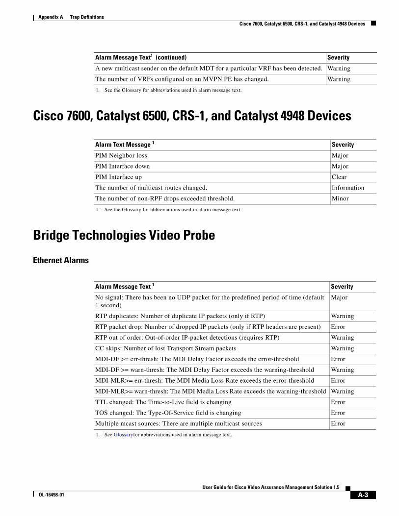
Appendix A Trap Definitions Cisco 7600, Catalyst 6500, CRS-1, and Catalyst 4948 Devices
Cisco 7600, Catalyst 6500, CRS-1, and Catalyst 4948 Devices
Bridge Technologies Video Probe
Ethernet Alarms
A new multicast sender on the default MDT for a particular VRF has been detected. Warning
The number of VRFs configured on an MVPN PE has changed. Warning
1. See the Glossary for abbreviations used in alarm message text.
Alarm Text Message 1
1. See the Glossary for abbreviations used in alarm message text.
Severity
PIM Neighbor loss Major
PIM Interface down Major
PIM Interface up Clear
The number of multicast routes changed. Information
The number of non-RPF drops exceeded threshold. Minor
Alarm Message Text 1
1. See Glossaryfor abbreviations used in alarm message text.
Severity
No signal: There has been no UDP packet for the predefined period of time (default 1 second)
Major
RTP duplicates: Number of duplicate IP packets (only if RTP) Warning
RTP packet drop: Number of dropped IP packets (only if RTP headers are present) Error
RTP out of order: Out-of-order IP-packet detections (requires RTP) Warning
CC skips: Number of lost Transport Stream packets Warning
MDI-DF >= err-thresh: The MDI Delay Factor exceeds the error-threshold Error
MDI-DF >= warn-thresh: The MDI Delay Factor exceeds the warning-threshold Warning
MDI-MLR>= err-thresh: The MDI Media Loss Rate exceeds the error-threshold Error
MDI-MLR>= warn-thresh: The MDI Media Loss Rate exceeds the warning-threshold Warning
TTL changed: The Time-to-Live field is changing Error
TOS changed: The Type-Of-Service field is changing Error
Multiple mcast sources: There are multiple multicast sources Error
Alarm Message Text1 (continued) Severity
A-3User Guide for Cisco Video Assurance Management Solution 1.5
OL-16498-01
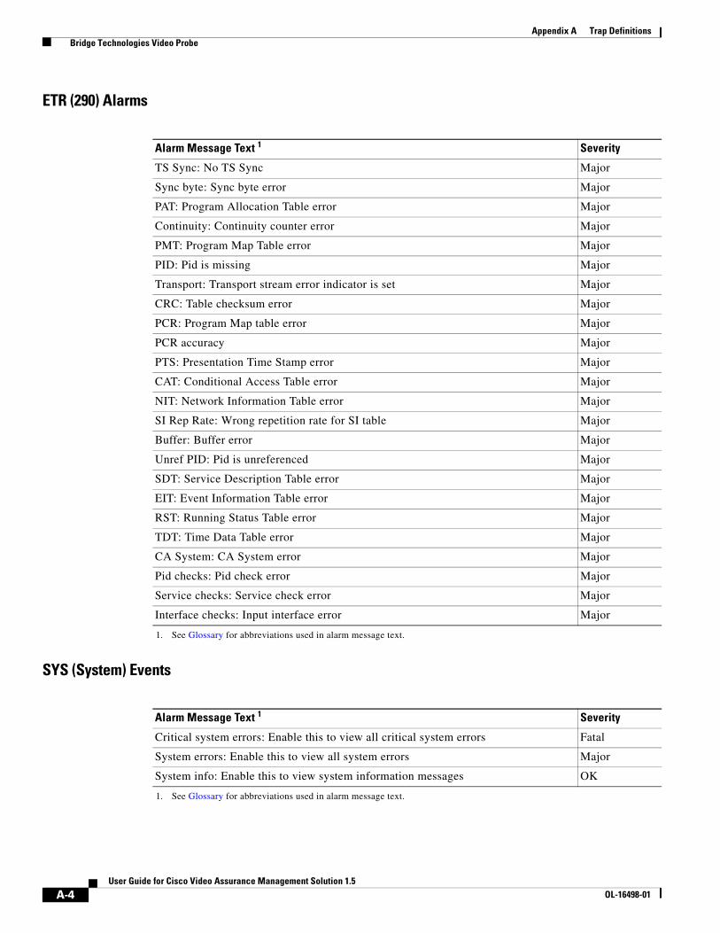
Appendix A Trap Definitions Bridge Technologies Video Probe
ETR (290) Alarms
SYS (System) Events
Alarm Message Text 1
1. See Glossary for abbreviations used in alarm message text.
Severity
TS Sync: No TS Sync Major
Sync byte: Sync byte error Major
PAT: Program Allocation Table error Major
Continuity: Continuity counter error Major
PMT: Program Map Table error Major
PID: Pid is missing Major
Transport: Transport stream error indicator is set Major
CRC: Table checksum error Major
PCR: Program Map table error Major
PCR accuracy Major
PTS: Presentation Time Stamp error Major
CAT: Conditional Access Table error Major
NIT: Network Information Table error Major
SI Rep Rate: Wrong repetition rate for SI table Major
Buffer: Buffer error Major
Unref PID: Pid is unreferenced Major
SDT: Service Description Table error Major
EIT: Event Information Table error Major
RST: Running Status Table error Major
TDT: Time Data Table error Major
CA System: CA System error Major
Pid checks: Pid check error Major
Service checks: Service check error Major
Interface checks: Input interface error Major
Alarm Message Text 1
1. See Glossary for abbreviations used in alarm message text.
Severity
Critical system errors: Enable this to view all critical system errors Fatal
System errors: Enable this to view all system errors Major
System info: Enable this to view system information messages OK
A-4User Guide for Cisco Video Assurance Management Solution 1.5
OL-16498-01
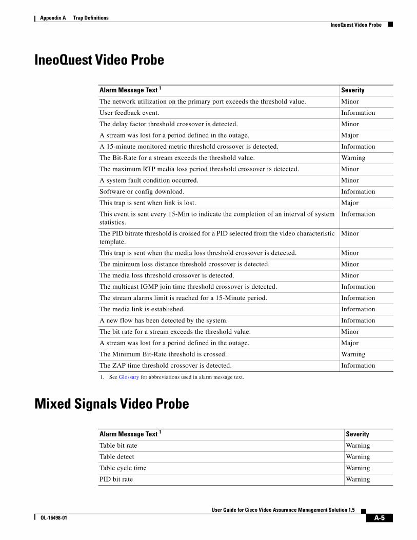
Appendix A Trap Definitions IneoQuest Video Probe
IneoQuest Video Probe
Mixed Signals Video Probe
Alarm Message Text 1
1. See Glossary for abbreviations used in alarm message text.
Severity
The network utilization on the primary port exceeds the threshold value. Minor
User feedback event. Information
The delay factor threshold crossover is detected. Minor
A stream was lost for a period defined in the outage. Major
A 15-minute monitored metric threshold crossover is detected. Information
The Bit-Rate for a stream exceeds the threshold value. Warning
The maximum RTP media loss period threshold crossover is detected. Minor
A system fault condition occurred. Minor
Software or config download. Information
This trap is sent when link is lost. Major
This event is sent every 15-Min to indicate the completion of an interval of system statistics.
Information
The PID bitrate threshold is crossed for a PID selected from the video characteristic template.
Minor
This trap is sent when the media loss threshold crossover is detected. Minor
The minimum loss distance threshold crossover is detected. Minor
The media loss threshold crossover is detected. Minor
The multicast IGMP join time threshold crossover is detected. Information
The stream alarms limit is reached for a 15-Minute period. Information
The media link is established. Information
A new flow has been detected by the system. Information
The bit rate for a stream exceeds the threshold value. Minor
A stream was lost for a period defined in the outage. Major
The Minimum Bit-Rate threshold is crossed. Warning
The ZAP time threshold crossover is detected. Information
Alarm Message Text 1 Severity
Table bit rate Warning
Table detect Warning
Table cycle time Warning
PID bit rate Warning
A-5User Guide for Cisco Video Assurance Management Solution 1.5
OL-16498-01
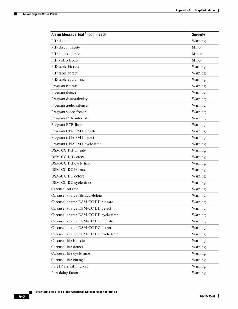
Appendix A Trap Definitions Mixed Signals Video Probe
PID detect Warning
PID discontinuity Minor
PID audio silence Minor
PID video freeze Minor
PID table bit rate Warning
PID table detect Warning
PID table cycle time Warning
Program bit rate Warning
Program detect Warning
Program discontinuity Warning
Program audio silence Warning
Program video freeze Warning
Program PCR interval Warning
Program PCR jitter Warning
Program table PMT bit rate Warning
Program table PMT detect Warning
Program table PMT cycle time Warning
DSM-CC DII bit rate Warning
DSM-CC DII detect Warning
DSM-CC DII cycle time Warning
DSM-CC DC bit rate Warning
DSM-CC DC detect Warning
DSM-CC DC cycle time Warning
Carousel bit rate Warning
Carousel source file add-delete Warning
Carousel source DSM-CC DII bit rate Warning
Carousel source DSM-CC DII detect Warning
Carousel source DSM-CC DII cycle time Warning
Carousel source DSM-CC DC bit rate Warning
Carousel source DSM-CC DC detect Warning
Carousel source DSM-CC DC cycle time Warning
Carousel file bit rate Warning
Carousel file detect Warning
Carousel file cycle time Warning
Carousel file change Warning
Port IP arrival interval Warning
Port delay factor Warning
Alarm Message Text 1 (continued) Severity
A-6User Guide for Cisco Video Assurance Management Solution 1.5
OL-16498-01
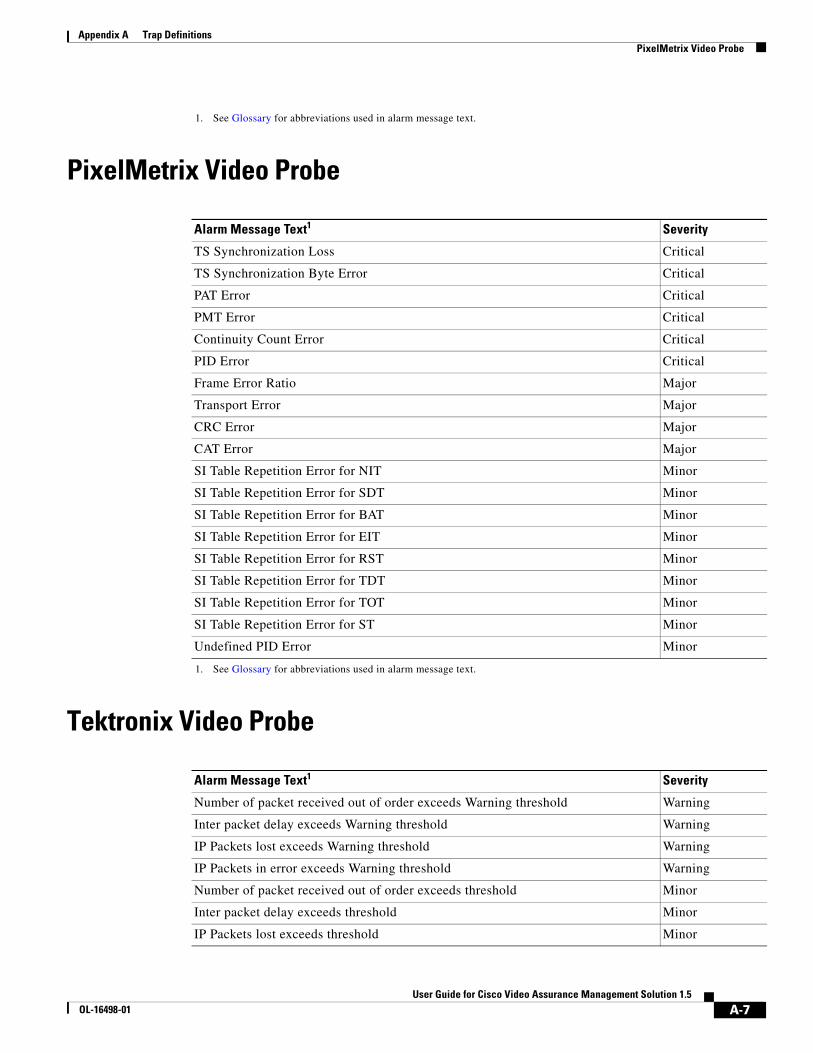
Appendix A Trap Definitions PixelMetrix Video Probe
PixelMetrix Video Probe
Tektronix Video Probe
1. See Glossary for abbreviations used in alarm message text.
Alarm Message Text1
1. See Glossary for abbreviations used in alarm message text.
Severity
TS Synchronization Loss Critical
TS Synchronization Byte Error Critical
PAT Error Critical
PMT Error Critical
Continuity Count Error Critical
PID Error Critical
Frame Error Ratio Major
Transport Error Major
CRC Error Major
CAT Error Major
SI Table Repetition Error for NIT Minor
SI Table Repetition Error for SDT Minor
SI Table Repetition Error for BAT Minor
SI Table Repetition Error for EIT Minor
SI Table Repetition Error for RST Minor
SI Table Repetition Error for TDT Minor
SI Table Repetition Error for TOT Minor
SI Table Repetition Error for ST Minor
Undefined PID Error Minor
Alarm Message Text1 Severity
Number of packet received out of order exceeds Warning threshold Warning
Inter packet delay exceeds Warning threshold Warning
IP Packets lost exceeds Warning threshold Warning
IP Packets in error exceeds Warning threshold Warning
Number of packet received out of order exceeds threshold Minor
Inter packet delay exceeds threshold Minor
IP Packets lost exceeds threshold Minor
A-7User Guide for Cisco Video Assurance Management Solution 1.5
OL-16498-01
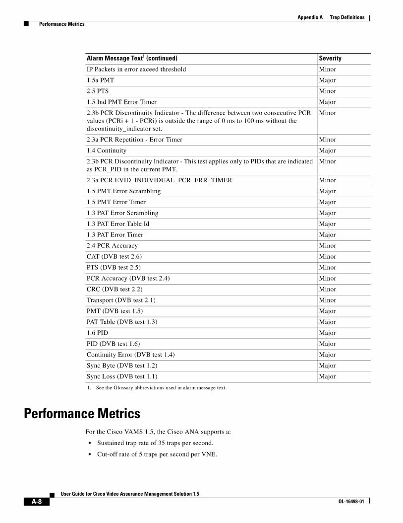
Appendix A Trap Definitions Performance Metrics
Performance MetricsFor the Cisco VAMS 1.5, the Cisco ANA supports a:
• Sustained trap rate of 35 traps per second.
• Cut-off rate of 5 traps per second per VNE.
IP Packets in error exceed threshold Minor
1.5a PMT Major
2.5 PTS Minor
1.5 Ind PMT Error Timer Major
2.3b PCR Discontinuity Indicator - The difference between two consecutive PCR values (PCRi + 1 - PCRi) is outside the range of 0 ms to 100 ms without the discontinuity_indicator set.
Minor
2.3a PCR Repetition - Error Timer Minor
1.4 Continuity Major
2.3b PCR Discontinuity Indicator - This test applies only to PIDs that are indicated as PCR_PID in the current PMT.
Minor
2.3a PCR EVID_INDIVIDUAL_PCR_ERR_TIMER Minor
1.5 PMT Error Scrambling Major
1.5 PMT Error Timer Major
1.3 PAT Error Scrambling Major
1.3 PAT Error Table Id Major
1.3 PAT Error Timer Major
2.4 PCR Accuracy Minor
CAT (DVB test 2.6) Minor
PTS (DVB test 2.5) Minor
PCR Accuracy (DVB test 2.4) Minor
CRC (DVB test 2.2) Minor
Transport (DVB test 2.1) Minor
PMT (DVB test 1.5) Major
PAT Table (DVB test 1.3) Major
1.6 PID Major
PID (DVB test 1.6) Major
Continuity Error (DVB test 1.4) Major
Sync Byte (DVB test 1.2) Major
Sync Loss (DVB test 1.1) Major
1. See the Glossary abbreviations used in alarm message text.
Alarm Message Text1 (continued) Severity
A-8User Guide for Cisco Video Assurance Management Solution 1.5
OL-16498-01

Appendix A Trap Definitions Performance Metrics
Cisco ANA drops traps that exceed the cut-off rate. For example, if a VNE receives six traps per second, the ANA drops the sixth trap. Also, the cut-off rate is cumulative. For example, for two VNEs, the cut-off rate is 10 traps per second.
A-9User Guide for Cisco Video Assurance Management Solution 1.5
OL-16498-01

Appendix A Trap Definitions Performance Metrics
A-10User Guide for Cisco Video Assurance Management Solution 1.5
OL-16498-01

User Guide for CiscOL-16498-01
A
P P E N D I X B End User License Agreement SupplementEND USER LICENSE AGREEMENT SUPPLEMENT FOR CISCO SYSTEMS NETWORK MANAGEMENT SOFTWARE: Cisco Video Assurance Management Solution Software
Dear Customer,
This End User License Agreement Supplement (“Supplement”) contains additional terms and conditions for the Software Product licensed under the End User License Agreement (“EULA”) between you and Cisco (collectively, the “Agreement”). Capitalized terms used in this Supplement but not defined will have the meanings assigned to them in the EULA. To the extent that there is a conflict between the terms and conditions of the EULA and this Supplement, the terms and conditions of this Supplement will take precedence.
In addition to the limitations set forth in the EULA on your access and use of the Software, you agree to comply at all times with the terms and conditions provided in this Supplement, including any restrictions on access and use of the Software. BY DOWNLOADING, INSTALLING, OR USING THE SOFTWARE, YOU ARE BINDING YOURSELF AND THE BUSINESS ENTITY THAT YOU REPRESENT (COLLECTIVELY, “CUSTOMER”) TO THE AGREEMENT. IF YOU DO NOT AGREE TO ALL OF THE TERMS OF THE AGREEMENT, THEN CISCO IS UNWILLING TO LICENSE THE SOFTWARE TO YOU AND (A) YOU MAY NOT DOWNLOAD, INSTALL OR USE THE SOFTWARE, AND (B) YOU MAY RETURN THE SOFTWARE (INCLUDING ANY UNOPENED CD PACKAGE AND ANY WRITTEN MATERIALS) FOR A FULL REFUND, OR, IF THE SOFTWARE AND WRITTEN MATERIALS ARE SUPPLIED AS PART OF ANOTHER PRODUCT, YOU MAY RETURN THE ENTIRE PRODUCT FOR A FULL REFUND. YOUR RIGHT TO RETURN AND REFUND EXPIRES 30 DAYS AFTER PURCHASE FROM CISCO OR AN AUTHORIZED CISCO RESELLER, AND APPLIES ONLY IF YOU ARE THE ORIGINAL END USER PURCHASER.
For purposes of the SEULA, the Product name and the Product description you have ordered is one or more of:
Cisco Video Assurance Management Solution 1.5
• VAMS1.0-3.6VNE4948—Video Assurance 1.0, Extension to 4948 (G2) VNE - ANA 3.6.3
• VAMS1.0-3.6VNE7600—Video Assurance 1.0, Extension to 7600 (G3) VNE - ANA 3.6.3
• VAMS1.0-3.6VNEG5—Video Assurance 1.0, Extension to CRS-1 (G5) VNE - ANA 3.6.3
• VAMS1.0-3.6VNEG6—Video Assurance 1.0, Extension to CRS-1 (G6) VNE - ANA 3.6.3
• VAMS1.0-3.6VNECMM—Video Assurance 1.0, Cisco Multicast Manager VNE - ANA 3.6.3
• VAMS1.0-3.6VNEIQ—IneoQuest Video Probe VNE - ANA 3.6.3
• VAMS1.0-3.6VNEMS—Mixed Signals Video Probe VNE - ANA 3.6.3
• VAMS1.0-3.6VNETK—Tektronix Video Probe VNE - ANA 3.6.3
B-1o Video Assurance Management Solution 1.5

Appendix B End User License Agreement Supplement
• VAMS1.0-3.6IQRTU—IneoQuest Video Probe RTU - Right to Use for one IQ probe
• VAMS1.0-3.6MSRTU—Mixed Signals Video Probe RTU - Right to Use for one MS probe
• VAMS1.0-3.6TKRTU—Tektronix Video Probe VNE RTU - Right to Use for one TK probe
VAMS 1.5 ANA Extensions:
• VAMS-ANA36VNE4948—VAMS 1, Extension to 4948 (G2) VNE - ANA 3.6
• VAMS-ANA36VNE7600—VAMS 1, Extension to 7600(G3) VNE - ANA 3.6
• VAMS-ANA36VNEG5—VAMS 1, Extension to CRS-1 (G5) VNE - ANA 3.6
• VAMS-ANA36VNEG6—VAMS 1, Extension to CRS-1 (G6) VNE - ANA 3.6
• VAMS-ANA36VNECMM—VAMS 1, Cisco Multicast Manager VNE - ANA 3.6
• VAMS-ANA36VNEIQ—VAMS 1, IneoQuest Video Probe VNE - ANA 3.6
• VAMS-ANA36VNETK—VAMS 1, Tektronix Video Probe VNE - ANA 3.6
• VAMS-ANA36QRTU—VAMS 1, IneoQuest Video Probe RTU - ANA 3.6
• VAMS-ANA36MSRTU—VAMS 1, Mixed Signals Video Probe RTU - ANA 3.6
• VAMS-ANA36VTKRTU—VAMS 1, Tektronix Video Probe RTU - ANA 3.6
VAMS 1.5 CIC Extensions
• VAMS1-CICMOM72-K9—VAMS 1, Extensions to CIC 7.2 ObjectServer/Webtop
• VAMS1-CICMOM72F-K9—VAMS 1, Extensions to CIC 7.2 ObjectServer/Webtop - Failover
• VAMS1-CICMOM72N-K9—VAMS 1, Extensions to CIC 7.2 ObjectServer/Webtop - Non Prod
• VAMS1-CICTBSM41-K9—VAMS 1, Extensions to CIC 7.2 TBSM 4.1
• VAMS1-CICTBSM41F-K9—VAMS 1, Extensions to CIC 7.2 TBSM 4.1 - Failover
• VAMS1-CICTBSM41N-K9—VAMS 1, Extensions to CIC 7.2 TBSM 4.1 - Non Prod
• VAMS1-CICIMPT40-K9—VAMS 1, Extensions to CIC 7.2 Impact 4.0
• VAMS1-CICIMPT40N-K9—VAMS 1, Extensions to CIC 7.2 Impact 4.0 - Non Prod
AMS 1.0
• AMS-1.0-MOM-K9—Assurance Management System 1.0 MoM Software and Probe RTU
• AMS-1.0-MOMP-K9—Assurance Management System 1.0 MoM Probe RTU
• AMS-1.0-MOMF-K9—Assurance Management System 1.0 MoM Software, Probe, BIGW Failover RTU
• AMS-1.0-MOMPF-K9—Assurance Management System 1.0 MoM Probe and Failover RTU
• AMS-1.0-MOMN-K9—Assurance Management System 1.0 MoM Software, Probe, BIGW, and Non Prod RTU
• AMS-1.0-MOMPN-K9—Assurance Management System 1.0 MoM Probe and Non Prod RTU
For purposes of this Supplement, the following definitions will apply:
“Cisco Video Assurance Management Solution” is software licensed to manage the assurance of video in a network environment. The Software is licensed per device managed.
B-2User Guide for Cisco Video Assurance Management Solution 1.5
OL-16498-01
Appendix B End User License Agreement Supplement ADDITIONAL LICENCE RESTRICTIONS
ADDITIONAL LICENCE RESTRICTIONS • Installation and Use. The Software components are provided to Customer solely to install, update,
supplement, or replace existing functionality of the applicable Network Management Software product.
Cisco Video Assurance Management Software is licensed and deployed such that it may be loaded on multiple processors. Customers must purchase software licenses for each device family to be managed in the Customer's environment.
• Customer may install and use following Software components:
– Cisco Video Assurance Management Solution - Video extensions to 4948 (G2) VNE license: Customer may install and run the Software on unlimited number of processors in the Customer's network environment, subject to a limitation on the number of 4948 devices managed that equals the number of ANA Group 2 licenses purchased from Cisco and in effect.
– Cisco Video Assurance Management Solution - Video extensions to 7600 (G3) VNE license: Customer may install and run the Software on unlimited number of processors in the Customer's network environment subject to a limitation on the number of 7600 devices managed that equals the number of ANA Group 3 licenses purchased from Cisco and in effect.
– Cisco Video Assurance Management Solution - Video extensions to CRS-1 (G5) VNE license: Customer may install and run the Software on unlimited number of processors in the Customer's network environment, subject to a limitation on the number CRS-1(G5) devices managed that equals the number of ANA Group 5 licenses purchased from Cisco and in effect.
– Cisco Video Assurance Management Solution - Video extensions to CRS-1 (G6) VNE license: Customer may install and run the Software on unlimited number of processors in the Customer's network environment, subject to a limitation on the number of CRS-1(G6) devices managed that equals the number of ANA Group 6 licenses purchased from Cisco and in effect.
– Cisco Video Assurance Management Solution - Cisco Multicast Manager VNE license: Customer may install and run the Software on unlimited number of processors in the Customer's network environment to enable ANA to interface with Cisco Multicast Manager installations in the Customer's network environment.
– Cisco Video Assurance Management Solution - IneoQuest Video Probe VNE license: Customer may install and run the Software on unlimited number of processors in the Customer's network environment, subject to a limitation on the number of IneoQuest probe devices managed that equals the number of IneoQuest licenses purchased from Cisco and in effect.
– Cisco Video Assurance Management Solution - Mixed Signals Video Probe VNE license: Customer may install and run the Software on unlimited number of processors in the Customer's network environment, subject to a limitation on the number of Mixed Signals probe devices managed that equals the number of Mixed Signals licenses purchased from Cisco and in effect.
– Cisco Video Assurance Management Solution - Tektronix Video Probe VNE license: Customer may install and run the Software on unlimited number of processors in the Customer's network environment, subject to a limitation on the number Tektronix probe devices managed that equals the number of Tektronix Video Probe licenses purchased from Cisco and in effect.
• Other license restrictions on software:
– Cisco Video Assurance Management Solution - IneoQuest Video Probe license: Each license permits the Customer to manage one IneoQuest probe device.
– Cisco Video Assurance Management Solution - Mixed Signals Video Probe RTU license: Each license permits the Customer to manage one Mixed Signals probe device.
B-3User Guide for Cisco Video Assurance Management Solution 1.5
OL-16498-01

Appendix B End User License Agreement Supplement DESCRIPTION OF OTHER RIGHTS AND LIMITATIONS
– Cisco Video Assurance Management Solution - Tektronix Video Probe license: Each license permits the Customer to manage one Tektronix probe device.
– Reproduction and Distribution. Customer may not reproduce nor distribute Software.
DESCRIPTION OF OTHER RIGHTS AND LIMITATIONS Please refer to the Cisco Systems, Inc. End User License Agreement
B-4User Guide for Cisco Video Assurance Management Solution 1.5
OL-16498-01

User Guide foOL-16498-01
G L O S S A R Y
A
Access privilege In computer security, the process of ensuring that only authorized users can access the resources of a computer system in authorized ways.
Activation script A command script that Cisco ANA applies to one or more VNEs to extend their configurations. You use Cisco ANA Command Builder to create activation scripts. The Cisco Video Assurance Management Solution runs an IPTV activation script on its VNEs.
Alarm An audible or visual signal at a device, such as a display station or printer, that is used to notify the user that a predefined condition exists.
Alarm Thresholding A mechanism by which Cisco ANA constantly monitors selected soft properties and generates an alarm every time they cross a user-defined threshold or violate a condition. See also Soft Properties.
ANA Active Network Abstraction. A Cisco resource management solution designed with a fully distributed OSS mediation platform which abstracts the network, its topology and its capabilities from the physical elements.
ANA EventVision ANA EventVision is a GUI application that serves as a browser for viewing and retrieving detailed information about the different types of system events and tickets that are generated within the Cisco ANA system. Monitoring EventVision helps predict and identify the sources of system problems, which assists in preventing future problems.
ANA Manage ANA Manage is a GUI tool in Cisco ANA that performs various system administration activities for simple system control.
Active Network
Abstraction
See ANA.
ANA NetworkVision ANA NetworkVision is the primary GUI for Cisco ANA. It is a surveillance tool providing total visibility for multi-vendor, multi-tier, multi-technology networks. It also supports fault and configuration functionality.
ANA NetworkVision supports the creation of multiple network maps to represent specific network views. Views can cover specific network segments, customer networks, or any other mix of network elements desired. Once the maps have been created, they are available for all connecting clients (with support for fine grained access privileges).
Authentication In computer security, (1) verification of the identity of a user or the user’s eligibility to access an object; (2) verification that a message has not been altered or corrupted; (3) a process that is used to verify the user of an information system or of protected resources.
Authorization In computer security, (1) the right granted to a user to communicate with or make use of a computer system; (2) the process of granting a user either complete or restricted access to an object, resource, or function.
GL-1r Cisco Video Assurance Management Solution 1.5
Glossary
Automation In IBM Tivoli/OMNIbus, the ObjectServer can respond automatically to specified alerts.
Autonomous Virtual
Machine
See AVM.
AVM Autonomous Virtual Machine. Java processes that provide the necessary distribution support platform for executing and monitoring multiple VNEs.
B
back-office The internal operations of an organization that are not accessible or visible to the general public.
back up To copy information to another location to ensure against loss of data. Contrast with restore.
C
Carrier Routing
System-1
See CRS-1
Cisco Multicast
Manager
A Web-based network management application that simplifies the holistic discovery, visualization, monitoring, and troubleshooting of multicast networks. CMM is applicable to multiple system operators that use multicast to transport video over IP.
Configuration The machines, devices, and programs that make up a system, subsystem, or network.
CPU Central Processing Unit.
CRC Cyclic Redundancy Check. Error-checking technique in which the frame recipient calculates a remainder by dividing frame contents by a prime binary divisor and compares the calculated remainder to a value stored in the frame by the sending node.
CRS-1 Carrier Routing System-1. A Cisco large-scale core router for carrier networks.
Cyclic Redundancy
Check
See CRC.
D
Deduplication Deduplication (also known as record linkage) is a task of finding the same (duplicate) entry in multiple files. You use deduplication when merging two or more data sets. Deduplication is a useful tool when performing data mining tasks, where the data originated from different sources or different organizations.
Delay Factor See DF.
Deploy To place files or install software into an operational environment.
Desginated Router See DR.
GL-2User Guide for Cisco Video Assurance Management Solution 1.5
OL-16498-01

Glossary
Device Any non-client, non-server part of a network managed by Tivoli software, including, but not limited to, cable set-top boxes and other pervasive devices.
DF Delay Factor. A time value indicating the amount of data that buffers must contain to eliminate jitter.
Digital Storage
Media - Command
and Control
See DSM-CC.
Digital Subscriber
Line Access
Multiplexer
See DSLAM.
Digital Video
Broadcast
See DVB.
Discovery The automatic detection of a topology change, such as finding new and deleted nodes or links within a network topology, or such as finding storage resources and devices within a network that are not yet being monitored.
Domain A logical grouping of resources in a network for the purpose of common management and administration.
Domain name In the Internet suite of protocols, a name of a host system. A domain name consists of a sequence of subnames that are separated by a delimiter character. For example, Cisco.com.
DR Designated Router. A router in a multiaccess network that designates the originate network link advertisements and establishes adjacencies with all routers in the network.
Drools rules engine Drools rules engine is a general-purpose expert-system generator and combines rule-based techniques and object-oriented programming. It also provides a customizable mechanism to add decision support and data flow control functions to business applications.
Drools rules engine is based on an object-oriented paradigm and uses user-defined rules to perform pattern matching on different conditions. The rules are written in a Java-like syntax, and are organized into source files (known as a rule files), which are plain ASCII files.
DSLAM Digital Subscriber Line Access Multiplexer. A device that connects many digital subscriber lines to a network by multiplexing the DSL traffic onto one or more network trunk lines.
DSM-CC Digital Storage Media - Command and Control. A toolkit for developing control channels associated with MPEG-1 and MPEG-2 streams.
DVB Digital Video Broadcast. A European standard for digital television.
E
EMS Element Management System. A system that manages a network of elements.
GL-3User Guide for Cisco Video Assurance Management Solution 1.5
OL-16498-01
Glossary
Element
Management
System
See EMS.
Event Any significant change in the state of a system resource, network resource, or network application. An event can be generated for a problem, for the resolution of a problem, or for the successful completion of a task.
F
Field The building block of which objects are composed. A field is characterized by a field name, a data type (integer, Boolean, character string, or enumerated value), and a set of flags that describe how the field is treated. A field can contain data only when it is associated with an object.
G
Gateway In the IP community, an older term referring to a routing device. Today, the term router is used to describe nodes that perform this function, and gateway refers to a special-purpose device that performs an application layer conversion of information from one protocol stack to another.
H
HDD Hard disk drive.
Health check A report that shows the values over time of one or more metrics, which can be selected from one or more schemas, for one or more components. Typically, a health check shows time-delineated, diagnostic data that shows the fluctuation of key indicators.
Host A computer that is connected to a network (such as the Internet or an Systems Network Architecture [SNA] network) and provides an access point to the network. Also, depending on the environment, the host may provide centralized control of the network. The host can be a client, a server, or both a client and a server simultaneously.
HFC Hybrid Fiber-Coaxial. Technology being developed by the cable TV industry to provide two-way, high-speed data access to the home by using a combination of fiber optics and traditional coaxial cable.
Hybrid Fiber-Coaxial See HFC.
I
iVMS IP Video Management System (iVMS) from Ineoquest Technologies has been added to CMM 2.5 to provide real-time alerts to allow for rapid fault isolation of customer impacting video events.
ICMP Internet Control Message Protocol. Network layer Internet protocol that reports errors and provides other information relevant to IP packet processing. Documented in RFC 792.
GL-4User Guide for Cisco Video Assurance Management Solution 1.5
OL-16498-01
Glossary
IGMP Internet Group Management Protocol. Used by IP hosts to report their multicast group memberships to an adjacent multicast router.
Internet Control
Message Protocol
See ICMP.
Internet Group
Management
Protocol
See IGMP.
Internet Protocol
Television
See IPT.
Internet Service
Monitors
See ISM.
IPTV Internet Protocol Television. Video transport over IP.
IPTV extensions Configurations that extend the capabilities of the VNEs to include functions that are unique to the Cisco Video Assurance Management Solution. These extensions are applied to supported VNEs with an activation script.
IP Video
Management
System
See iVMS.
ISM Internet Service Monitors. A collection of software components that monitors the status and performance of Internet services such as e-mail, Dynamic Host Configuration Protocol (DHCP), Domain Name Service (DNS), and Remote Authentication Dial-In User Service (RADIUS). To assist CIC users in integrating CIC with ISM, CIC includes utilities you can run after installing CIC and ISM. These utilities customize the ISM installation to function more smoothly with CIC.
J
Java EventLists See JEL.
JEL Java EventLists. Java EventLists use passive software probes to collect network events from a wide variety of management environments. Then, JEL distributes color-coded views (output from the Netcool/OMNIbus ObjectServer memory-resident SQL data repository) of networked services to operators who monitor service levels. When combined, the topology displays and Java EventLists are updated in real time, giving managers a collaborative network management environment.
M
Management
Information Base
See MIB.
Map A named collection of objects, symbols, submaps, and their relationships, all of which represent the network topology. See topology.
GL-5User Guide for Cisco Video Assurance Management Solution 1.5
OL-16498-01
Glossary
MDT Multicast Distribution Tree. A distribution tree that controls the path that IP multicast traffic takes through the network to deliver traffic to all receivers. The two basic types of multicast distribution trees are source trees and shared trees.
Media Loss Rate See MLR.
MIB Management Information Base. Network management protocol, such as SNMP, uses and maintains a database of network management information. The value of a MIB object can be changed or retrieved by using SNMP commands, usually through a GUI network management system.
MLR Media Loss Rate. The number of lost or out-of-order media packets per second.
Motion Picture
Experts Group
See MPEG.
MPEG Motion Picture Experts Group. Standard for compressing video. MPEG1 is a bit stream standard for compressed video and audio optimized to fit into a bandwidth of 1.5 Mb/s. Intended for higher quality video-on-demand applications, MPEG2 runs at data rates between 4 and 9 Mb/s. Intended for 64-kb/s connections, MPEG4 is a low-bit-rate compression algorithm.
MPLS Multiprotocol Label Switching. Switching method that forwards IP traffic by using a label. This label instructs the routers and the switches in the network where to forward the packets based on preestablished IP routing information.
MVPN Multicast VPN.
Multicast
Distribution Tree
See MDT.
Multicast VPN See MVPN.
Multiprotocol Label
Switching
See MPLS.
N
NE Network Element. A user-named physical component or device existing in the network.
Netcool/Tivoli An application that integrates the CIC server product with the Tivoli network management application and allows Tivoli to manage a CIC sever installation.
Network Element See NE.
Network Time
Protocol
See NTP.
NTP Network Time Protocol. Protocol built on top of TCP that ensures accurate local time-keeping with reference to radio and atomic clocks located on the Internet. This protocol is capable of synchronizing distributed clocks in milliseconds over long time periods.
GL-6User Guide for Cisco Video Assurance Management Solution 1.5
OL-16498-01
Glossary
O
Object Identifier See OID.
OID Object Identifier. Values are defined in specific MIB modules. The Event MIB allows a user or an NMS to watch over specified objects and to set event triggers based on existence, threshold, and boolean tests. An event occurs when a trigger is fired; this means that a specified test on an object returns a value of true. To create a trigger, a user or an NMS configures a trigger entry in the mteTriggerTable of the Event MIB. This trigger entry specifies the OID of the object to be watched. For each trigger entry type, corresponding tables (existence, threshold, and boolean tables) are populated with the information required for carrying out the test. The MIB can be configured so that when triggers are activated (fired) either an SNMP Set is performed, a notification is sent out to the interested host, or both.
Operations Support
Systems/Business
Support Systems
See OSS/BSS.
OSS/BSS Operations Support Systems/Business Support Systems. Operations support systems (OSS) and business support systems are a set of programs that help a communications service provider monitor, control, analyze, and manage a telephone or computer network.
P
Packet ID See PID.
Packets per second See PPS.
PAT Program Association Table. A table that lists the PIDs that are associated with the PMTs in the transport stream.
PCR Program Clock Reference. A clock reference on a program PID that helps to present programs on time and at the right speed.
PE Provider Edge. A router at the edge of a network service provider area.
PID Packet ID. The ID of a packet in a transport stream.
PIM Protocol Independent Multicast. Multicast routing architecture that allows the addition of IP multicast routing on existing IP networks. PIM is a unicast routing protocol which is independent and can be operated in two modes: dense and sparse.
PMT Program Map Table. A table that provides information about a program on a video transport stream. The PMT lists the PIDs of the streams associated with the program.
Polling (1) The process whereby stations are invited, one at a time, to transmit. The polling process usually involves the sequential interrogation of several data stations. (2) In network management, the process by which a manager interrogates one or more managed nodes at regular intervals. (3) The process by which databases are interrogated at regular intervals to determine if data needs to be transmitted.
PPS Packets per second.
GL-7User Guide for Cisco Video Assurance Management Solution 1.5
OL-16498-01
Glossary
Presentation Time
Stamp
See PTS.
Program
Association Table
See PAT.
Program Clock
Reference
See PCR.
Program Map Table See PMT.
Protocol
Independent
Multicast
See PIM.
Provider Edge See PE.
Provision To provide, deploy, and track a service or component.
Provisioning The process of setting up and maintaining a user’s access to a system.
PTS Presentation Time Stamp. The time stamp when a video or audio frame must be presented to the user.
Q
QAM Quadratrue Amplitude Modulation. Method for encoding digital data in an analog signal in which each combination of phase and amplitude represents one of sixteen four-bit patterns. Also refers to devices that encode digital cable channels for transmission over cable.
Quadrature
Amplitude
Modulation
See QAM.
QoS Quality of Service. Measure of performance for a transmission system that reflects its transmission quality and service availability.
Quality of Service See QoS.
R
RDBMS Relational Database Management System. A collection of hardware and software that organizes and provides access to a relational database.
Realtime Transport
Protocol
See RTP.
Registry The data store that contains access and configuration information for users, systems, and software.
Relational database A database that can be perceived as a set of tables and manipulated in accordance with the relational model of data.
GL-8User Guide for Cisco Video Assurance Management Solution 1.5
OL-16498-01
Glossary
Relational database
management
system
See RDBMS.
Rendezvous Point See RP.
Reverse Path
Forwarding
See RPF.
Root-cause analysis The process of determining the actual cause of a network problem. For example, when a device on a network cannot be reached, it might be because of a problem with the device or a problem with a network component that is used to reach that device.
RP Rendezvous Point. Router specified in PIM sparse mode implementations to track membership in multicast groups and to forward messages to known multicast group addresses.
RPF Reverse Path Forwarding. Multicasting technique in which a multicast datagram is forwarded out of all but the receiving interface if the receiving interface is the one used to forward unicast datagrams to the source of the multicast datagram. Non-RPF packets, also called RPF failure packets, are RPF packets that have been transmitted backwards, against the flow from the source.
RTP Realtime Transport Protocol. IP transport protocol that provides media-specific time stamp data for real-time flows.
Rule A set of logical statements that enable the event server to recognize relationships among events and to execute automated responses accordingly. See also event.
Run time The time period during which a computer program is executing. A run-time environment is an execution environment.
S
Schema The set of statements, expressed in a data definition language, that completely describe the structure of a database. In a relational database, the schema defines the tables, the fields in each table, and the relationships between fields and tables.
Secure sockets layer See SSL.
Service provider Any company that provides services for a fee to its customers, such as telecommunication companies, application service providers, enterprise IT, and Internet service providers (ISPs). These fee services include application provisioning, application hosting, service level agreement management, and others.
Set-top box See STB.
SHE Super Head End. Network location for live feeds for the broadcast video service. This site contains the real-time encoders used for the broadcast video service, along with the asset distribution systems for on-demand services. This site may also contain back-office systems such as the subscriber database. The SHE typically resides in the core of the transport network.
Simple Network
Management
Protocol
See SNMP.
GL-9User Guide for Cisco Video Assurance Management Solution 1.5
OL-16498-01
Glossary
SNMP Simple Network Management Protocol. Network management protocol used almost exclusively in TCP/IP networks. SNMP provides a means to monitor and control network devices, and to manage configurations, statistics collection, performance, and security.
Soft Properties Cisco ANA offers the soft properties mechanism to enable user-configurable extensions of device modeling, which can cover any unsupported MIB variable. This mechanism enables adding new monitored NE properties in runtime to the default set of supported properties.
Every soft property is implemented through a set of definitions that determine how to retrieve, parse and display a certain MIB variable from the NE. The definition process is done through a simple GUI utility, and does not require system restart. Soft properties are retrieved from the NE by using SNMP, or Telnet/SSH.
See also Alarm Thresholding.
SSL Secure sockets layer. A security protocol that provides communication privacy. SSL enables client/server applications to communicate in a way that is designed to prevent eavesdropping, tampering, and message forgery.
STB Set-top box. A set-top box (STB) or set-top unit (STU) is a device that connects to a television and an external source of signal, turning the signal into content which is then displayed on the television screen.
Structured Query
Language
See SQL.
SQL Structured Query Language. A database computer language designed for the retrieval and management of data in relational database management systems (RDBMS), database schema creation and modification, and database object access control management.
SQL is a standard interactive and programming language for querying and modifying data and managing databases. Although SQL is both an ANSI and an ISO standard, many database products support SQL with proprietary extensions to the standard language. The core of SQL is formed by a command language that allows the retrieval, insertion, updating, and deletion of data, and performing management and administrative functions.
Super Head End See SHE.
T
TCA Threshold Crossing Alert. A system message that alerts the operator when a provisionable threshold has been crossed.
Threshold A customizable value for defining the acceptable tolerance limits (maximum, minimum, or reference limit) for an application resource or system resource. When the measured value of the resource is greater than the maximum value, less than the minimum value, or equal to the reference value, an exception is raised.
Threshold Crossing
Alert
See TCA.
Topology Physical arrangement of network nodes and media within an enterprise networking structure.
GL-10User Guide for Cisco Video Assurance Management Solution 1.5
OL-16498-01
Glossary
V
VHO Video Hub Office. Network location of the video server complex, which includes the video sources for on-demand services and real-time encoders for local television stations. A VHO typically serves a metropolitan area of between 100,000 and 1,000,000 homes.
Video Hub Office See VHO.
Video Switching
Office
See VSO.
Virtual Network
Element
See VNE.
Virtual Private
Network
See VPN.
VNE Virtual Network Element. A virtual representation of a single network element as a modeled component. VNEs all communicate with each other to present ANA-based applications with a single, common device abstraction for network element discovery, configuration, status collection, fault analysis and other basic network functions. VNEs can be extended to support new application functionality.
VPN Virtual Private Network. Enables IP traffic to travel securely over a public TCP/IP network by encrypting all traffic from one network to another. A VPN uses tunneling to encrypt all information at the IP level.
VPN
routing/forwarding
See VRF.
VRF VPN routing/forwarding. A VRF consists of an IP routing table, a derived forwarding table, a set of interfaces that use the forwarding table, and a set of rules and routing protocols that determine what goes into the forwarding table.
VSO Video Switching Office. VSOs house aggregation routers that aggregate traffic from subscriber homes.
Z
ZAP Zone Announcement Protocol. A multicast protocol for discovering the multicast administrative scope zones that are relevant at a particular location. See RFC 2776.
Zone
Announcement
Protocol
See ZAP.
GL-11User Guide for Cisco Video Assurance Management Solution 1.5
OL-16498-01

Glossary
GL-12User Guide for Cisco Video Assurance Management Solution 1.5
OL-16498-01
User Guide foOL-16498-01
I N D E X
Symbols
$ANAROOT
ANA installation directory 4-1
Numerics
4948
switch
Catalyst 1-2, 1-6
6500
switch
Catalyst 1-6
7600
router 1-6
A
Activate on creation
check box 5-3
activation script
IPTV 1-21
active network abstraction
See ANA
administration
CMM
application tool 1-10
administrator
password 3-2
alarm
link-down
disable 6-20
link-up
disable 6-20
managing 1-26
open 6-20
port-down
disable 6-20
port-up
disable 6-20
root-cause 6-20
sources 6-20
viewing 1-26
alerts
CMM 1-9
ANA
authentication 3-2
client license 1-25
common builder tool 1-21, 1-23
EventVision 1-26, 6-20
gateway 5-2
GUI 1-23
manage 1-24, 5-3
navigation tree 5-2
Network Map 5-4
network map 5-1
NetworkVision 1-24, 1-25, 5-4, 5-16, 6-20
software tools
manage 1-24
solution component 1-20
traps 1-9
VNE 1-22
ANA installation directory
$ANAROOT 4-1
analysis
root cause 6-20
IN-1r Cisco Video Assurance Management Solution 1.5
Index
ANA Manage
perform, system administration 1-24
authentication
ANA 3-2
autonomous virtual machine
See AVM
AVM
create 5-2
B
before you install 3-1
Bridge Technologies
trap definitions A-3
video probe 1-26
browsing
event 1-26
button
Add Trap Receiver 5-6
Execute 5-16
Start 5-5
C
cable network
VAMS in a 1-5
carrier routing system 1
See CRS-1
casualty
correlation 6-20
Catalyst 4948
switch 1-2, 1-6
trap definitions A-3
Catalyst 6500
switch 1-6
trap definitions A-3
central database
ObjectServer 1-2
IN-2User Guide for Cisco Video Assurance Management Solution 1.5
check
connectivity 6-20
health A-1
check box
Activate on creation 5-3
choose 5-3
New AVM, from drop-down menu 5-2
New VNE 5-3
CIC/Netcool
solution component 1-12
Cisco 7600
trap definitions A-3
cisco multicast manager
See CMM
Cisco Multicast Manager 2.5.1 (table) 1-10
Cisco Video Assurance Management Solution in a Cable Network (figure) 1-5
Cisco Video Management Solution Components (figure) 1-3
Cisco Video Management Solution in a Wireline Network (figure) 1-4
client license
ANA 1-25
CMM 1-10
alerts 1-9
application tool
administration 1-10
multicast manager 1-11
configure 5-5
metrics 1-9
Sun Microsystems server 1-9
trap definitions A-1
x86 server 1-8
CMM diagnostics
MSDP 1-11
common builder tool
ANA 1-21, 1-23
components
solution 1-6
configuration 1-21
OL-16498-01
Index
IGMP 1-24
log level 5-18
management and inventory 1-21
PIM 1-24
configure
CMM 5-5
EventVision 1-26
polling intervals 5-5
threshold 5-14, A-2
VAMS 1.5 5-1
video probe 5-14
connections
device 1-25
connectivity
check 6-20
multilayer 1-25
network inventory 1-25
correlation
by key 6-20
casualty 6-20
scenario 6-20
create
AVM 5-2
VNEs 5-1, 5-2
CRS-1
trap definitions A-3
CVAMS 1-1
introduction 1-2
overview 1-1
D
defining
user account 1-25
delay factor
threshold A-5
designated router
See DR
detection and isolation
UseOL-16498-01
fault 6-20
device
connections 1-25
directory
iptv/scripts/ 3-2
uninstallation 4-1
disable
link-down, alarm 6-20
link-up, alarm 6-20
port-down, alarm 6-20
port-up, alarm 6-20
discovery 5-5
DR
global configuration, polling intervals 5-5
multicast data 1-9
drop-down list
Configured Trap Receivers 5-6
drop-down menu
choose
New AVM 5-2
duplicated
event 1-22
DVD
drive 1-17, 1-19, 1-20
VAMS 1.5 3-1, 4-1
E
element
virtual network 1-2
enable
SSH 5-3
Telnet 5-3
error
threshold A-3
event
browsing 1-26
duplicated 1-22
log 1-22
IN-3r Guide for Cisco Video Assurance Management Solution 1.5
Index
managing 1-26
MIB 1-24
syslog 1-22
time, day, severity, device 1-22
viewing 1-26
event and alarm
management 1-22
event management and integration
Netcool/Impact 1-15
EventVision
ANA 1-26, 6-20
configure 1-26
tool 1-23
F
fault 1-22
detection and isolation 6-20
management 1-22, 6-20
GUI 1-23
flow
by key 6-20
G
gateway
ANA 5-2
generic
VNE 1-26
generic ICMP
VNE 1-26
generic SNMP
VNE 1-26
graphical user interface
See GUI
group
polling 1-25
protection 1-25
IN-4User Guide for Cisco Video Assurance Management Solution 1.5
GUI
ANA 1-23
NetworkVision 1-25
fault
management 1-23
H
hardware
preinstallation 2-1
hardware rate limiter
See HWRL
health
check A-1
HFC
high-speed data access, two-way 1-5
high
threshold A-1, A-2
HTTP
protocol, web browser 1-14
HTTPS
secure protocol, web browser 1-14
HWRL
counters 6-19
hybrid fiber-coaxial
See HFC
hyper-text transport protocol
See HTTP
hyper-text transport protocol with SSL
See HTTPS
I
IBM Tivoli Monitoring
See ITM
ICMP
polling 1-22
IGMP
OL-16498-01
Index
configuration 1-24
IGMP join time
threshold A-5
IneoQuest
trap definitions A-5
video probe 1-2, 1-26
information
license 1-1
SNMP 5-14
install
VAMS 1.5 3-1
installation
script 3-2
integrity service 6-20
internet control message protocol
See ICMP
internet group management protocol
See IGMP
internet protocol television
IPTV 1-21
intervals
polling 1-22
introduction
CVAMS 1-2
inventory
logical 1-22
physical 1-22
IPTV
activation script 1-21
internet protocol television 1-21
iptv/scripts/
directory 3-2
ITM
key component, monitoring 1-15
J
Java EventList
See JEL
UseOL-16498-01
JEL
alerts, using Webtop 1-14
K
key performance indicator
See KPI
KPI
business metrics 1-15
L
Layer 2
multicast bandwidth 1-9
multicast traffic 1-9
transport 1-24
Layer 3
multicast bandwidth 1-9
multicast traffic 1-9
multicast trees 1-9
license
information 1-1
link
topology
persistent 1-25
static 1-25
Linux
platform 1-10
log
event 1-22
logical
inventory 1-22
log level configuration 5-18
M
manage
alarms 1-26
IN-5r Guide for Cisco Video Assurance Management Solution 1.5
Index
ANA 5-3
software tools 1-24
events 1-26
NE 1-25
provisioning 1-26
security events 1-26
syslogs 1-26
system events 1-26
traps 1-26
management 1-22
event and alarm 1-22
fault 6-20
multicast 1-23
security 1-23
video 1-23
management and inventory 1-21
management information base
See MIB
managing
user account 1-25
map
network 5-16
topology 1-25
medial loss period
threshold A-5
media loss rate
See MLR
memory database
ObjectServer 1-13, 1-16
metrics
CMM 1-9
performance A-8
MIB
event 1-24
Minimum Bit-Rate
threshold A-5
minimum loss distance
threshold A-5
Mixed Signals
IN-6User Guide for Cisco Video Assurance Management Solution 1.5
trap definitions A-5
video probe 1-2, 1-26
model
network maps 1-25
monitor
NE 1-25
monitored metric
threshold A-5
moving pictures expert group
See MPEG
MPEG
video, carries 1-26
MSDP
CMM diagnostics 1-11
multicast
management 1-23
routes 1-24
multicast bandwidth
Layer 2 1-9
Layer 3 1-9
multicast manager
CMM
application
tool 1-11multicast source discovery protocol
See MSDP
multicast traffic
Layer 2 1-9
Layer 3 1-9
multicast trees
Layer 3 1-9
multilayer
connectivity 1-25
N
navigation tree
ANA 5-2
NE
OL-16498-01
Index
add, delete, modify 1-24
ANA-managed 1-22
manage 1-25
monitor 1-25
troubleshoot 1-25
Netcool
ObjectServer 1-13
OMNIbus
service level management system 1-12
view 5-21
Webtop 1-14
Netcool/GUI Foundation
See NGF
Netcool/Impact
event management and integration 1-15
Netcool/OMNIbus
service level management system 1-13
network
map 5-16
network element
See NE
network inventory
connectivity 1-25
viewing 1-25
Network MAP
ANA 5-4
network map
ANA 5-1
network maps
model 1-25
view 1-25
network time protocol
See NTP
NetworkVision
ANA 1-24, 1-25, 5-4, 5-16, 6-20
use 1-25
New VNE 5-3
NGF
application, server 1-16
UseOL-16498-01
non-reverse path forwarding
See non-RPF
non-RPF
drops 1-24
packets
failure 1-24
notes
release 3-1
NTP
troubleshoot, Ethernet switches 6-19
O
object identifiers
See OID
ObjectServer
central database 1-2
memory database 1-13, 1-16
Netcool 1-13
OID
on-demand
polling 1-23
on-demand
polling 1-23
open
alarm 6-20
operations support system
See OSS
operations support systems/business support systems
See OSS/BSS
OSS
applications 1-20
OSS/BSS
applications 1-17
overview
CVAMS 1-1
IN-7r Guide for Cisco Video Assurance Management Solution 1.5
Index
P
packets
failure
non-RPF 1-24
password
administrator 3-2
PE
device configurations 1-12
percentage
threshold A-1
performance
metrics A-8
physical
inventory 1-22
PID bitrate
threshold A-5
PIM
configuration 1-24
PixelMetrix
trap definitions A-7
video probe 1-26
platform
Linux 1-10
Solaris 1-10
polling
group 1-25
ICMP 1-22
intervals 1-22
configure 5-5
on-demand 1-23
SNMP 1-21
Telnet 1-21
polling and CPU utilization 1-22
polling groups
30-minute config 5-3
60-minute config 5-3
preinstallation
hardware 2-1
IN-8User Guide for Cisco Video Assurance Management Solution 1.5
prerequisites 2-1
software 2-1
prerequisites 5-1
preinstallation 2-1
protection
group 1-25
protocol independent multicast
See PIM
provider edge
See PE
provisioning
managing 1-26
viewing 1-26
Q
QoS
Ethernet switches 6-19
troubleshoot, Ethernet switches 6-19
quality of service
See QoS
R
receiver
trap 5-6
release
notes 3-1
rendezvous point
See RP
reverse path forwarding
See RPF
review
events 1-26
root cause
analysis 6-20
root-cause
alarm 6-20
OL-16498-01
Index
router
7600 1-6
routes 1-25
multicast 1-24
RP
multicast data 1-9
RPF
failure packets 1-24
S
scenario
correlation 6-20
script
installation 3-2
setCimsCredentials.sh 3-2
uninstall 4-1
security
management 1-23
security event
managing 1-26
viewing 1-26
service level management
See SLM
service level management system
Netcool
OMNIbus 1-12
Netcool/OMNIbus 1-13
set
threshold 5-1, 5-5, A-2
setCimsCredentials.sh
script 3-2
settings
video probe 5-14
SHE
network location, wireline network 1-4
simple network management protocol
See SNMP
SLM
UseOL-16498-01
Netcool/omnibus management system 1-12
SNMP
information 5-14
polling 1-21
trap 1-24
ciscoPimInterfaceDown 1-23
ciscoPimInterfaceUp 1-23
pimNeighborLoss 1-23
traps 1-9, 1-26
soft properties
TCA 1-21
software
preinstallation 2-1
software components 1-10
CMM 1-10
Solaris
platform 1-10
solution
component 1-6
solution component
ANA 1-20
CIC/Netcool 1-12
solution components and version information (table) 1-7
sources
alarm 6-20
SQL
Netcool/Omnibus ObjectServer data source 1-15
SSH
enable 5-3
starting and stopping
VNE 1-24
structured query language
See SQL
Sun Microsystems server
CMM 1-9
super head end
See SHE
switch
Catalyst 4948 1-2, 1-6
IN-9r Guide for Cisco Video Assurance Management Solution 1.5
Index
Catalyst 6500 1-6
syslog
managing 1-26
system event
managing 1-26
viewing 1-26
T
tab
General 5-3
ICMP 5-3
Polling 5-3
SNMP 5-3
TBSM
critical business services, visualize and assure 1-15
service dashboard 1-2
visualization tool 1-2
TCA
soft properties 1-21
Tektronix
trap definitions A-7
video probe 1-2, 1-26
Telnet
enable 5-3
polling 1-21
test
integrity service 6-20
threshold 1-9, 1-26, A-3
configure 5-14, A-2
delay factor A-5
error A-3
high A-1, A-2
IGMP join time A-5
low A-1, A-2
media loss period A-5
Minimum Bit-Rate A-5
minimum loss distance A-5
monitored metric A-5
IN-10User Guide for Cisco Video Assurance Management Solution 1.5
multicast 5-5
percentage A-1
PID bitrate A-5
set 5-1, 5-5, A-2
value A-5
values 1-21
warning A-3, A-7
ZAP time A-5
threshold-crossing alert
See TCA
Tivoli Business and Services Manager
See TBSM
Tivoli Business Service Manager
See TBSM
Tool
drop-down menu
Administration 5-5
tool
EventVision 1-23
topology
map 1-25
viewing 1-25
traffic 1-25
transport
Layer 2 1-24
trap
managing 1-26
receiver 5-6
SNMP 1-24
viewing 1-26
trap definitions
Bridge Technologies A-3
Catalyst 4948 A-3
Catalyst 6500 A-3
Cisco 7600 A-3
CMM A-1
CRS-1 A-3
IneoQuest A-5
Mixed Signals A-5
OL-16498-01
Index
PixelMetrix A-7
Tektronix A-7
traps
ANA 1-9
SNMP 1-9, 1-26
troubleshoot
NE 1-25
troubleshooting 1-24
Cisco VAMS 1.5 6-1
U
uninstall
script 4-1
VAMS 1.5 4-1
uninstallation
directory 4-1
use
NetworkVision 1-25
user account
defining 1-25
managing 1-25
V
value
threshold
value A-5
values
threshold 1-21
VAMS 1.5
configure 5-1
DVD 3-1, 4-1
install 3-1
uninstall 4-1
VHO
network location, video server complex 1-4
video
UseOL-16498-01
management 1-23
video hub office
See VHO
video probe
Bridge Technologies 1-26, 5-14
configure 5-14
IneoQuest 1-2, 1-26, 5-14
Mixed Signals 1-2, 1-26, 5-15
PixelMetrix 1-26, 5-15
settings 5-14
Tektronix 1-2, 1-26, 5-15
video steam
delay in 5-14
video stream
jitter in 5-14
video transport network
made up of
Cisco 7600 router, Cisco CRS-1, and Catalyst 4948 switch 1-20
network elements in 1-6
view
alarms 1-26
network maps 1-25
provisioning 1-26
security events 1-26
syslogs 1-26
system events 1-26
traps 1-26
viewing
network inventory 1-25
syslog 1-26
topology 1-25
virtual network element
See VNE
VNE
ANA 1-22
generic 1-26
generic ICMP 1-26
generic SNMP 1-26
IN-11r Guide for Cisco Video Assurance Management Solution 1.5
Index
ICMP 1-21
SNMP 1-21
starting and stopping 1-24
VNE Information for Cisco VAMS 1.6 (table) 5-2
VNEs
create 5-1, 5-2
VNEs for the Cisco VAMS (table) 1-21
VPN routing/forwarding instances
See VRF
W
warning
threshold A-3, A-7
web GUI
Webtop 1-2
Webtop
Netcool 1-14
web GUI 1-2
wireline network
VAMS in 1-4
X
x86 server
CMM 1-8
Z
ZAP time
threshold A-5
IN-12User Guide for Cisco Video Assurance Management Solution 1.5
OL-16498-01


![CISCO VIDEO [Schreibgeschützt] - beb-ev.de · Cisco Confidential 4 Video / Telefonie Video Telepresence Cisco Telepresence Video Positionierung Welche Lösungen sind vorhanden? Immersive](https://img.pdfslide.us/doc/110x75/5dd10b76d6be591ccb63f342/cisco-video-schreibgeschtzt-beb-evde-cisco-confidential-4-video-telefonie.jpg)