Embed Size (px)
Citation preview
Barricade™ Home Gateway ADSL Router with 802.11 b/g wireless capabilities
SMC7901WBRA2 B1
USER GUIDE

20 MasonIrvine, CA 92618Phone: (949) 679-8000
SMC7901WBRA2 B1User Guide
November 2009Pub. # 149100000005A
E112009-DT-R01
Information furnished by SMC Networks, Inc. (SMC) is believed to be accurate and reliable. However, no responsibility is assumed by SMC for its use, nor for any infringements of patents or other rights of third parties which may result from its use. No license is granted by implication or otherwise under any patent or patent rights of SMC. SMC reserves the right to change specifications at any time without notice.
Copyright © 2009 by
SMC Networks, Inc.
20 Mason
Irvine, CA 92618
All rights reserved
Trademarks:
SMC is a registered trademark; and Barricade, EZ Switch, TigerStack, TigerSwitch, and TigerAccess are trademarks of SMC Networks, Inc. Other product and company names are trademarks or registered trademarks of their respective holders.

– 4 –
WARRANTY AND PRODUCT REGISTRATIONTo register SMC products and to review the detailed warranty statement, please refer to the Support Section of the SMC Website at http://www.smc.com.
COMPLIANCES
FEDERAL COMMUNICATION COMMISSION INTERFERENCE STATEMENT
This equipment has been tested and found to comply with the limits for a Class B digital device, pursuant to Part 15 of the FCC Rules. These limits are designed to provide reasonable protection against harmful interference in a residential installation. This equipment generates, uses and can radiate radio frequency energy and, if not installed and used in accordance with the instructions, may cause harmful interference to radio communications. However, there is no guarantee that interference will not occur in a particular installation. If this equipment does cause harmful interference to radio or television reception, which can be determined by turning the equipment off and on, the user is encouraged to try to correct the interference by one of the following measures:
◆ Reorient or relocate the receiving antenna
◆ Increase the separation between the equipment and receiver
◆ Connect the equipment into an outlet on a circuit different from that to which the receiver is connected
◆ Consult the dealer or an experienced radio/TV technician for help
This device complies with Part 15 of the FCC Rules. Operation is subject to the following two conditions: (1) This device may not cause harmful interference, and (2) this device must accept any interference received, including interference that may cause undesired operation.
FCC Caution: Any changes or modifications not expressly approved by the party responsible for compliance could void the user's authority to operate this equipment.
For product available in the USA/Canada market, only channel 1~11 can be operated. Selection of other channels is not possible.
This device and its antenna(s) must not be co-located or operation in conjunction with any other antenna or transmitter.
IMPORTANT NOTE:FCC RADIATION EXPOSURE STATEMENT
This equipment complies with FCC radiation exposure limits set forth for an uncontrolled environment. This equipment should be installed and operated with minimum distance 20 cm between the radiator and your body.
– 5 –
COMPLIANCES
The availability of some specific channels and/or operational frequency bands are country dependent and are firmware programmed at the factory to match the intended destination. The firmware setting is not accessible by the end user.
EC CONFORMANCE DECLARATION Marking by the above symbol indicates compliance with the Essential Requirements of the R&TTE Directive of the European Union (1999/5/EC). This equipment meets the following conformance standards:
◆ EN 300 328 - Technical requirements for 2.4 GHz radio equipment
◆ EN 301 489-1 / EN 301 489-17 - EMC requirements for radio equipment
This device is intended for use in the following European Community and EFTA countries:
Requirements for indoor vs. outdoor operation, license requirements and allowed channels of operation apply in some countries as described below:
◆ In Italy the end-user must apply for a license from the national spectrum authority to operate this device outdoors.
◆ In Belgium outdoor operation is only permitted using the 2.46 - 2.4835 GHz band: Channel 13.
◆ In France outdoor operation is only permitted using the 2.4 - 2.454 GHz band: Channels 1 - 7.
NOTE: The user must use the configuration utility provided with this product to ensure the channels of operation are in conformance with the spectrum usage rules for European Community countries as described below.
◆ This device will automatically limit the allowable channels determined by the current country of operation. Incorrectly entering the country of operation may result in illegal operation and may cause harmful interference to other systems. The user is obligated to ensure the device is operating according to the channel limitations, indoor/outdoor restrictions and license requirements for each European Community country as described in this document.
◆Austria ◆Belgium ◆Cyprus ◆Czech Republic ◆Denmark
◆Estonia ◆Finland ◆France ◆Germany ◆Greece
◆Hungary ◆ Iceland ◆ Ireland ◆ Italy ◆Latvia
◆Liechtenstein ◆Lithuania ◆Luxembourg ◆Malta ◆Netherlands
◆Norway ◆Poland ◆Portugal ◆Slovakia ◆Slovenia
◆Spain ◆Sweden ◆Switzerland ◆United Kingdom
– 6 –
COMPLIANCES
◆ This device may be operated indoors only in all countries of the European Community using the 2.4 GHz band: Channels 1 - 13, except where noted below.
◆ In Italy the end-user must apply for a license from the national spectrum authority to operate this device outdoors.
◆ In Belgium outdoor operation is only permitted using the 2.46 - 2.4835 GHz band: Channel 13.
◆ In France outdoor operation is only permitted using the 2.4 - 2.454 GHz band: Channels 1 - 7.
DECLARATION OF CONFORMITY IN LANGUAGES OF THE EUROPEAN COMMUNITY
CzechČesky
SMC tímto prohlašuje, že tento Radio LAN device je ve shodě se základními požadavky a dalšími příslušnými ustanoveními směrnice 1999/5/ES.
EstonianEesti
Käesolevaga kinnitab SMC seadme Radio LAN device vastavust direktiivi 1999/5/EÜ põhinõuetele ja nimetatud direktiivist tulenevatele teistele asjakohastele sätetele.
English Hereby, SMC, declares that this Radio LAN device is in compliance with the essential requirements and other relevant provisions of Directive 1999/5/EC.
FinnishSuomi
Valmistaja SMC vakuuttaa täten että Radio LAN device tyyppinen laite on direktiivin 1999/5/EY oleellisten vaatimusten ja sitä koskevien direktiivin muiden ehtojen mukainen.
DutchNederlands
Hierbij verklaart SMC dat het toestel Radio LAN device in overeenstemming is met de essentiële eisen en de andere relevante bepalingen van richtlijn 1999/5/EG
Bij deze SMC dat deze Radio LAN device voldoet aan de essentiële eisen en aan de overige relevante bepalingen van Richtlijn 1999/5/EC.
FrenchFrançais
Par la présente SMC déclare que l'appareil Radio LAN device est conforme aux exigences essentielles et aux autres dispositions pertinentes de la directive 1999/5/CE
SwedishSvenska
Härmed intygar SMC att denna Radio LAN device står I överensstämmelse med de väsentliga egenskapskrav och övriga relevanta bestämmelser som framgår av direktiv 1999/5/EG.
DanishDansk
Undertegnede SMC erklærer herved, at følgende udstyr Radio LAN device overholder de væsentlige krav og øvrige relevante krav i direktiv 1999/5/EF
GermanDeutsch
Hiermit erklärt SMC, dass sich dieser/diese/dieses Radio LAN device in Übereinstimmung mit den grundlegenden Anforderungen und den anderen relevanten Vorschriften der Richtlinie 1999/5/EG befindet". (BMWi)
Hiermit erklärt SMC die Übereinstimmung des Gerätes Radio LAN device mit den grundlegenden Anforderungen und den anderen relevanten Festlegungen der Richtlinie 1999/5/EG. (Wien)
GreekΕλληνική
με την παρουσα SMC δηλωνει οτι radio LAN device συμμορφωνεται προσ τισ ουσιωδεισ απαιτησεισ και τισ λοιπεσ σχετικεσ διαταξεισ τησ οδηγιασ 1999/5/εκ.
HungarianMagyar
Alulírott, SMC nyilatkozom, hogy a Radio LAN device megfelel a vonatkozó alapvetõ követelményeknek és az 1999/5/EC irányelv egyéb elõírásainak.
ItalianItaliano
Con la presente SMC dichiara che questo Radio LAN device è conforme ai requisiti essenziali ed alle altre disposizioni pertinenti stabilite dalla direttiva 1999/5/CE.
LatvianLatviski
Ar šo SMC deklarē, ka Radio LAN device atbilst Direktīvas 1999/5/EK būtiskajām prasībām un citiem ar to saistītajiem noteikumiem.
LithuanianLietuvių
Šiuo SMC deklaruoja, kad šis Radio LAN device atitinka esminius reikalavimus ir kitas 1999/5/EB Direktyvos nuostatas.
– 7 –
COMPLIANCES
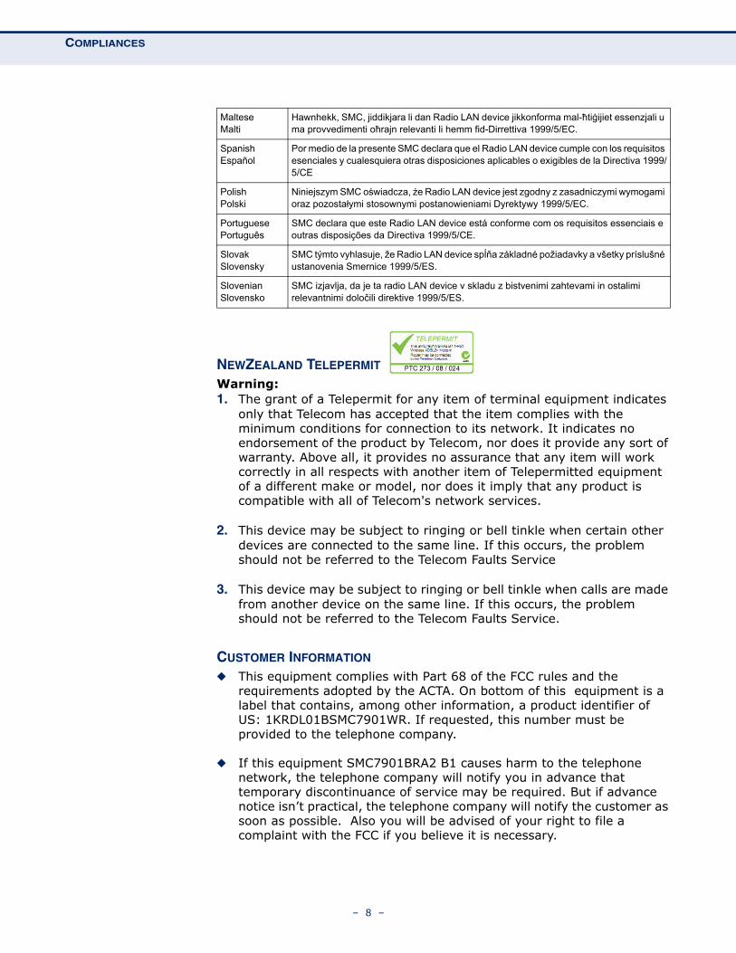
NEWZEALAND TELEPERMIT
Warning: 1. The grant of a Telepermit for any item of terminal equipment indicates
only that Telecom has accepted that the item complies with the minimum conditions for connection to its network. It indicates no endorsement of the product by Telecom, nor does it provide any sort of warranty. Above all, it provides no assurance that any item will work correctly in all respects with another item of Telepermitted equipment of a different make or model, nor does it imply that any product is compatible with all of Telecom's network services.
2. This device may be subject to ringing or bell tinkle when certain other devices are connected to the same line. If this occurs, the problem should not be referred to the Telecom Faults Service
3. This device may be subject to ringing or bell tinkle when calls are made from another device on the same line. If this occurs, the problem should not be referred to the Telecom Faults Service.
CUSTOMER INFORMATION
◆ This equipment complies with Part 68 of the FCC rules and the requirements adopted by the ACTA. On bottom of this equipment is a label that contains, among other information, a product identifier of US: 1KRDL01BSMC7901WR. If requested, this number must be provided to the telephone company.
◆ If this equipment SMC7901BRA2 B1 causes harm to the telephone network, the telephone company will notify you in advance that temporary discontinuance of service may be required. But if advance notice isn’t practical, the telephone company will notify the customer as soon as possible. Also you will be advised of your right to file a complaint with the FCC if you believe it is necessary.
MalteseMalti
Hawnhekk, SMC, jiddikjara li dan Radio LAN device jikkonforma mal-ħtiġijiet essenzjali u ma provvedimenti oħrajn relevanti li hemm fid-Dirrettiva 1999/5/EC.
SpanishEspañol
Por medio de la presente SMC declara que el Radio LAN device cumple con los requisitos esenciales y cualesquiera otras disposiciones aplicables o exigibles de la Directiva 1999/5/CE
PolishPolski
Niniejszym SMC oświadcza, że Radio LAN device jest zgodny z zasadniczymi wymogami oraz pozostałymi stosownymi postanowieniami Dyrektywy 1999/5/EC.
PortuguesePortuguês
SMC declara que este Radio LAN device está conforme com os requisitos essenciais e outras disposições da Directiva 1999/5/CE.
SlovakSlovensky
SMC týmto vyhlasuje, že Radio LAN device spĺňa základné požiadavky a všetky príslušné ustanovenia Smernice 1999/5/ES.
SlovenianSlovensko
SMC izjavlja, da je ta radio LAN device v skladu z bistvenimi zahtevami in ostalimi relevantnimi določili direktive 1999/5/ES.
– 8 –
COMPLIANCES
◆ The telephone company may make changes in its facilities, equipment, operations or procedures that could affect the operation of the equipment. If this happens, the telephone company will provide advance notice in order for you to make necessary modification to maintain uninterrupted service.
◆ If you experience trouble with this equipment, you disconnect it from the network until the problem has been corrected or until you are sure that the equipment is not malfunctioning.
◆ Please follow instructions for repairing if any (e.g. battery replacement section); otherwise do not alternate or repair any parts of device except specified.
◆ Connection to party line service is subject to state tariffs. Contact the state public utility commission, public service commission or corporation commission for information.
◆ If the telephone company requests information on what equipment is connected to their lines, inform them of:
a. The telephone number that this unit is connected to,
b. The ringer equivalence number 0.1B
c. The USOC jack required RJ-11 C/W, and
d. The FCC Registration Number US: 1KRDL01BSMC7901WR
Item (b) and (d) are indicated on the label. The ringer equivalence number (REN) is used to determine how many devices can be connected to your telephone line. In most areas, the sum of the RENs of all devices on any one line should not exceed five (5.0). If too many devices are attached, they may not ring properly.
◆ If your home has specially wired alarm equipment connected to the telephone line, ensure the installation of this equipment does not disable alarm equipment, consult your telephone company or a qualified installer.
SERVICE REQUIREMENTS
In the event of equipment malfunction, all repairs should be performed by our Company or an authorized agent. It is the responsibility of users requiring service to report the need for service to our Company or to one of our authorized agents.
Service can be facilitated through our office at:
SMC Networks North America
20 Mason
Irvine, CA 92618
USA
– 9 –
ABOUT THIS GUIDE
PURPOSE This guide gives specific information on how to install the ADSL Router and its physical and performance related characteristics. It also gives information on how to operate and use the management functions of the ADSL Router.
AUDIENCE This guide is intended for use by network administrators who are responsible for installing, operating, and maintaining network equipment; consequently, it assumes a basic working knowledge of LANs (Local Area Networks), the Internet Protocol (IP), and Simple Network Management Protocol (SNMP).
CONVENTIONS The following conventions are used throughout this guide to show information:
NOTE: Emphasizes important information or calls your attention to related features or instructions.
CAUTION: Alerts you to a potential hazard that could cause loss of data, or damage the system or equipment.
WARNING: Alerts you to a potential hazard that could cause personal injury.
RELATED PUBLICATIONS As part of the ADSL Router’s software, there is an online web-based help that describes all management related features.
REVISION HISTORY This section summarizes the changes in each revision of this guide.
NOVEMBER 2009 REVISIONThis is the first revision of this guide. It is valid for software release v1.2.0.15.
– 10 –
CONTENTS
WARRANTY AND PRODUCT REGISTRATION 4
COMPLIANCES 5
ABOUT THIS GUIDE 10
CONTENTS 11
FIGURES 16
TABLES 19
SECTION I GETTING STARTED 20
1 INTRODUCTION 21
Key Hardware Features 21
Description of Capabilities 21
Applications 22
Package Contents 23
Hardware Description 24
Antenna 26
LED Indicators 27
Ethernet Port 28
Power Connector and Button 28
Reset Button 28
2 INSTALLING THE ADSL ROUTER 29
System Requirements 29
Location Selection 29
Mounting on a Horizontal Surface 30
Mounting on a Wall 31
Connecting and Powering On 32
– 11 –
CONTENTS
3 INITIAL CONFIGURATION 35
ISP Settings 35
Connecting to the Login Page 35
Home Page and Main Menu 36
Common Web Page Buttons 37
Wizard 38
Step 1 - Internet Connection Settings 38
Step 2 - LAN Settings 39
Step 3 - WLAN Settings 40
Step 4 - Apply Changes 42
SECTION II WEB CONFIGURATION 45
4 STATUS INFORMATION 47
System 48
WAN 49
LAN 50
WLAN 51
Traffic Statistics 52
DSL Statistics 53
ARP Table 55
Bridging Table 56
Routing Table 57
5 WAN CONFIGURATION 59
Channel Configuration 59
Current ATM VC Table 60
Auto PVC Settings 63
ATM Settings 63
Current ATM VC Table 64
ADSL Settings 65
ADSL Modulation 65
AnnexL Option 66
AnnexM Option 66
ADSL Capability 66
ADSL Tone 67
– 12 –
CONTENTS
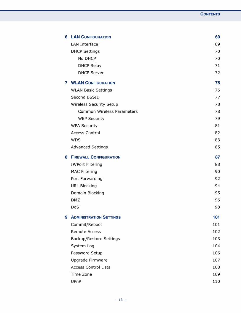
6 LAN CONFIGURATION 69
LAN Interface 69
DHCP Settings 70
No DHCP 70
DHCP Relay 71
DHCP Server 72
7 WLAN CONFIGURATION 75
WLAN Basic Settings 76
Second BSSID 77
Wireless Security Setup 78
Common Wireless Parameters 78
WEP Security 79
WPA Security 81
Access Control 82
WDS 83
Advanced Settings 85
8 FIREWALL CONFIGURATION 87
IP/Port Filtering 88
MAC Filtering 90
Port Forwarding 92
URL Blocking 94
Domain Blocking 95
DMZ 96
DoS 98
9 ADMINISTRATION SETTINGS 101
Commit/Reboot 101
Remote Access 102
Backup/Restore Settings 103
System Log 104
Password Setup 106
Upgrade Firmware 107
Access Control Lists 108
Time Zone 109
UPnP 110
– 13 –
CONTENTS
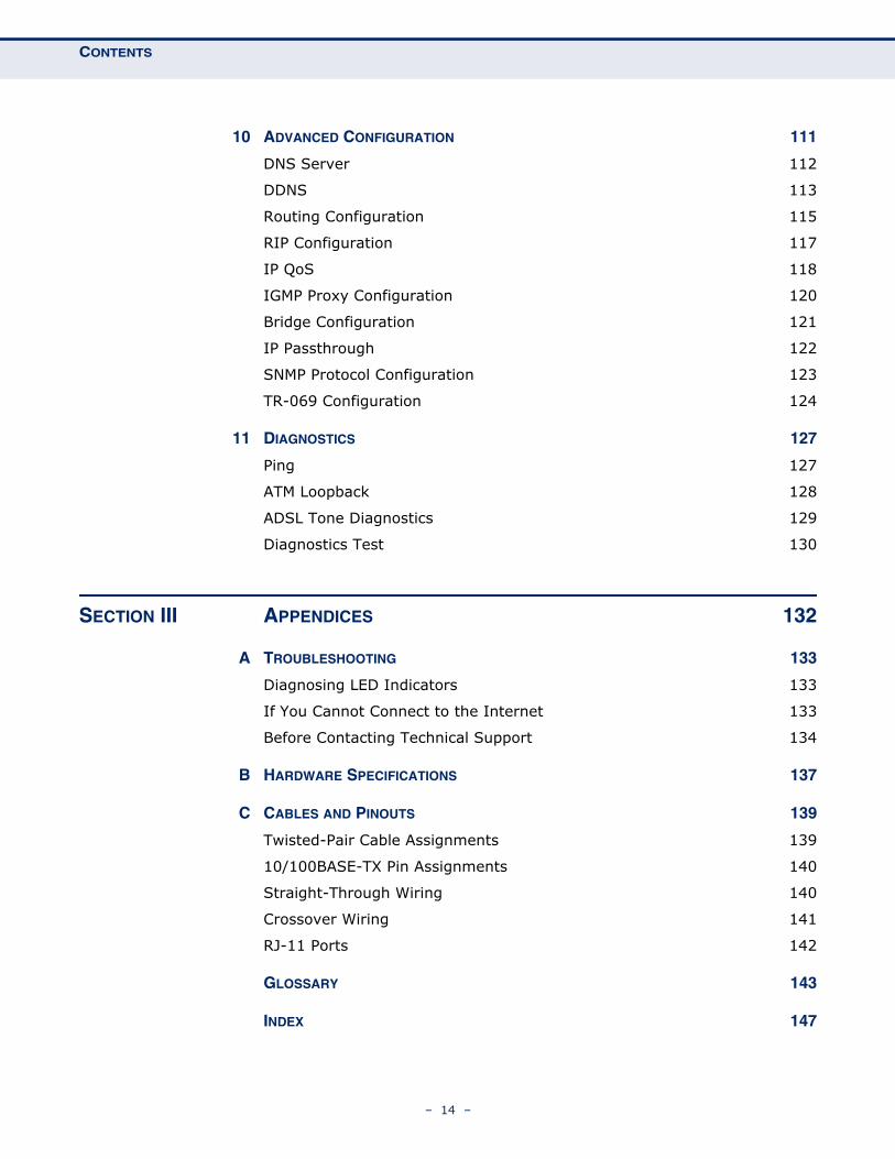
10 ADVANCED CONFIGURATION 111
DNS Server 112
DDNS 113
Routing Configuration 115
RIP Configuration 117
IP QoS 118
IGMP Proxy Configuration 120
Bridge Configuration 121
IP Passthrough 122
SNMP Protocol Configuration 123
TR-069 Configuration 124
11 DIAGNOSTICS 127
Ping 127
ATM Loopback 128
ADSL Tone Diagnostics 129
Diagnostics Test 130
SECTION III APPENDICES 132
A TROUBLESHOOTING 133
Diagnosing LED Indicators 133
If You Cannot Connect to the Internet 133
Before Contacting Technical Support 134
B HARDWARE SPECIFICATIONS 137
C CABLES AND PINOUTS 139
Twisted-Pair Cable Assignments 139
10/100BASE-TX Pin Assignments 140
Straight-Through Wiring 140
Crossover Wiring 141
RJ-11 Ports 142
GLOSSARY 143
INDEX 147
– 14 –

CONTENTS
– 15 –
FIGURES
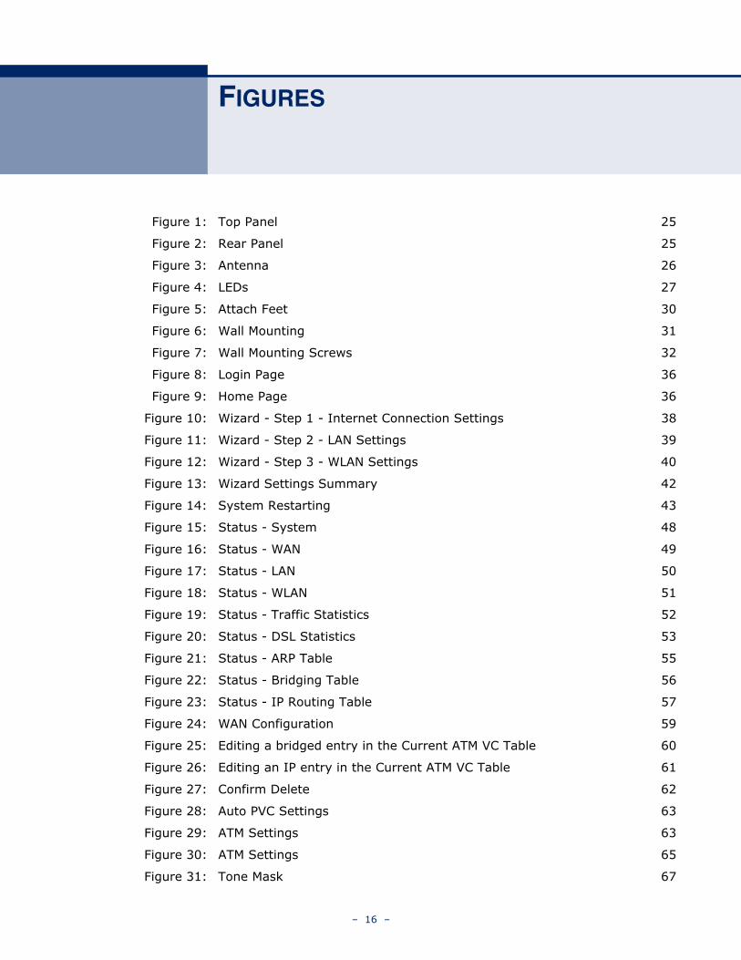
Figure 1: Top Panel 25
Figure 2: Rear Panel 25
Figure 3: Antenna 26
Figure 4: LEDs 27
Figure 5: Attach Feet 30
Figure 6: Wall Mounting 31
Figure 7: Wall Mounting Screws 32
Figure 8: Login Page 36
Figure 9: Home Page 36
Figure 10: Wizard - Step 1 - Internet Connection Settings 38
Figure 11: Wizard - Step 2 - LAN Settings 39
Figure 12: Wizard - Step 3 - WLAN Settings 40
Figure 13: Wizard Settings Summary 42
Figure 14: System Restarting 43
Figure 15: Status - System 48
Figure 16: Status - WAN 49
Figure 17: Status - LAN 50
Figure 18: Status - WLAN 51
Figure 19: Status - Traffic Statistics 52
Figure 20: Status - DSL Statistics 53
Figure 21: Status - ARP Table 55
Figure 22: Status - Bridging Table 56
Figure 23: Status - IP Routing Table 57
Figure 24: WAN Configuration 59
Figure 25: Editing a bridged entry in the Current ATM VC Table 60
Figure 26: Editing an IP entry in the Current ATM VC Table 61
Figure 27: Confirm Delete 62
Figure 28: Auto PVC Settings 63
Figure 29: ATM Settings 63
Figure 30: ATM Settings 65
Figure 31: Tone Mask 67
– 16 –
FIGURES
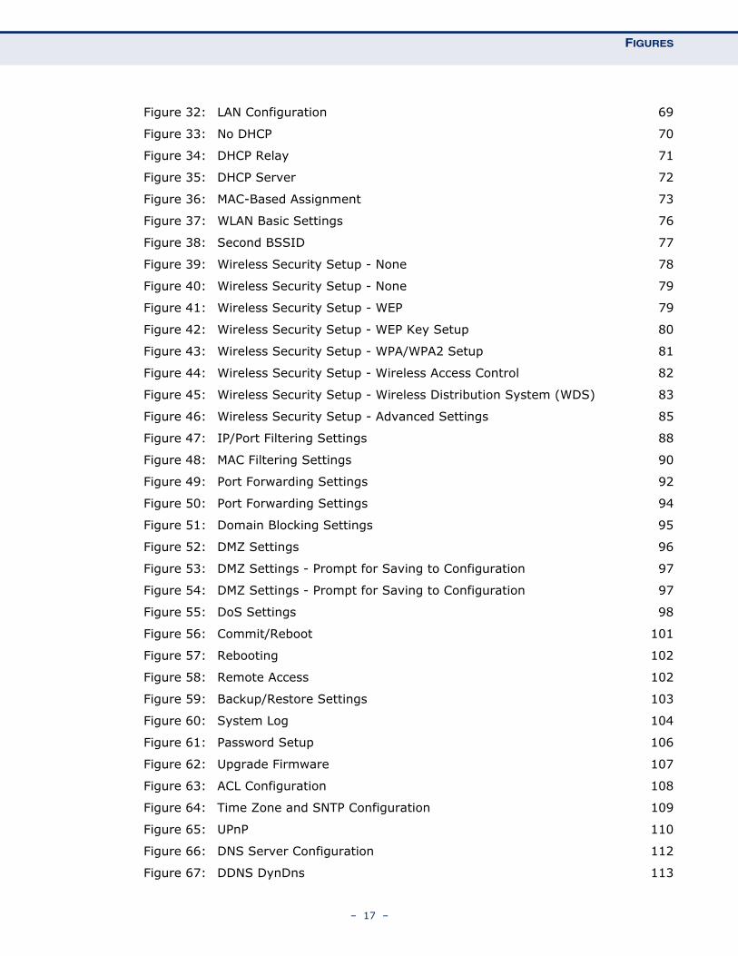
Figure 32: LAN Configuration 69
Figure 33: No DHCP 70
Figure 34: DHCP Relay 71
Figure 35: DHCP Server 72
Figure 36: MAC-Based Assignment 73
Figure 37: WLAN Basic Settings 76
Figure 38: Second BSSID 77
Figure 39: Wireless Security Setup - None 78
Figure 40: Wireless Security Setup - None 79
Figure 41: Wireless Security Setup - WEP 79
Figure 42: Wireless Security Setup - WEP Key Setup 80
Figure 43: Wireless Security Setup - WPA/WPA2 Setup 81
Figure 44: Wireless Security Setup - Wireless Access Control 82
Figure 45: Wireless Security Setup - Wireless Distribution System (WDS) 83
Figure 46: Wireless Security Setup - Advanced Settings 85
Figure 47: IP/Port Filtering Settings 88
Figure 48: MAC Filtering Settings 90
Figure 49: Port Forwarding Settings 92
Figure 50: Port Forwarding Settings 94
Figure 51: Domain Blocking Settings 95
Figure 52: DMZ Settings 96
Figure 53: DMZ Settings - Prompt for Saving to Configuration 97
Figure 54: DMZ Settings - Prompt for Saving to Configuration 97
Figure 55: DoS Settings 98
Figure 56: Commit/Reboot 101
Figure 57: Rebooting 102
Figure 58: Remote Access 102
Figure 59: Backup/Restore Settings 103
Figure 60: System Log 104
Figure 61: Password Setup 106
Figure 62: Upgrade Firmware 107
Figure 63: ACL Configuration 108
Figure 64: Time Zone and SNTP Configuration 109
Figure 65: UPnP 110
Figure 66: DNS Server Configuration 112
Figure 67: DDNS DynDns 113
– 17 –
FIGURES
Figure 68: DDNS TZO 113
Figure 69: Static Routing 115
Figure 70: Dynamic Routing 117
Figure 71: IP QoS 118
Figure 72: IGMP Configuration 120
Figure 73: Bridge Configuration 121
Figure 74: IP Passthrough 122
Figure 75: SNMP Configuration 123
Figure 76: TR-069 Configuration 124
Figure 77: Ping 127
Figure 78: Ping Results 128
Figure 79: ATM Loopback 128
Figure 80: ADSL Tone Diagnostics 129
Figure 81: Diagnostics Test 130
Figure 82: RJ-45 Connector 139
Figure 83: Straight Through Wiring 141
Figure 84: Crossover Wiring 141
Figure 85: RJ-11 Wire Pairs 142
– 18 –
TABLES
Table 1: Key Hardware Features 21
Table 2: LED Behavior 27
Table 3: LED Indicators 133
Table 4: 10/100BASE-TX MDI and MDI-X Port Pinouts 140
Table 5: RJ-11 Port Pinouts 142
– 19 –
SECTION I
GETTING STARTED
This section provides an overview of the ADSL Router, and describes how to install and mount the unit. It also describes the basic settings required to access the management interface and run the setup Wizard.
This section includes these chapters:
◆ “Introduction” on page 21
◆ “Installing the ADSL Router” on page 29
◆ “Initial Configuration” on page 35
– 20 –
1 INTRODUCTION
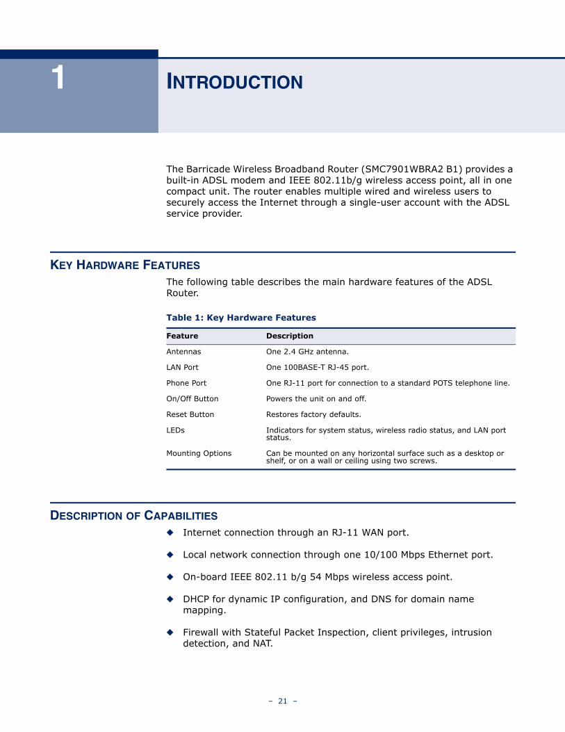
The Barricade Wireless Broadband Router (SMC7901WBRA2 B1) provides a built-in ADSL modem and IEEE 802.11b/g wireless access point, all in one compact unit. The router enables multiple wired and wireless users to securely access the Internet through a single-user account with the ADSL service provider.
KEY HARDWARE FEATURES
The following table describes the main hardware features of the ADSL Router.
DESCRIPTION OF CAPABILITIES
◆ Internet connection through an RJ-11 WAN port.
◆ Local network connection through one 10/100 Mbps Ethernet port.
◆ On-board IEEE 802.11 b/g 54 Mbps wireless access point.
◆ DHCP for dynamic IP configuration, and DNS for domain name mapping.
◆ Firewall with Stateful Packet Inspection, client privileges, intrusion detection, and NAT.
Table 1: Key Hardware Features
Feature Description
Antennas One 2.4 GHz antenna.
LAN Port One 100BASE-T RJ-45 port.
Phone Port One RJ-11 port for connection to a standard POTS telephone line.
On/Off Button Powers the unit on and off.
Reset Button Restores factory defaults.
LEDs Indicators for system status, wireless radio status, and LAN port status.
Mounting Options Can be mounted on any horizontal surface such as a desktop or shelf, or on a wall or ceiling using two screws.
– 21 –
CHAPTER 1 | IntroductionDescription of Capabilities
◆ NAT also enables multi-user Internet access via a single user account, and virtual server functionality (providing protected access to Internet services such as Web, FTP, e-mail, and Telnet).
◆ VPN pass-through (IPSec-ESP Tunnel mode, L2TP, PPTP).
◆ User-definable application sensing tunnel supports applications requiring multiple connections.
◆ Easy setup through a Web browser on any operating system that supports TCP/IP.
◆ Compatible with all popular Internet applications.
In addition, the access point functionality offers full network management capabilities through an easy to configure web interface, and support for Simple Network Management tools.
APPLICATIONS Many advanced networking features are provided by the Barricade:
◆ Wireless and Wired LAN — The Barricade provides connectivity to wired 10/100 Mbps devices, and wireless IEEE 802.11b compatible devices, making it easy to create a network in small offices or homes.
◆ Internet Access — This device supports Internet access through a DSL connection. Since many DSL providers use PPPoE or PPPoA to establish communications with end users, the Barricade includes built-in clients for these protocols, eliminating the need to install these services on your computer.
◆ Shared IP Address — The Barricade provides Internet access for up to 253 users via a single shared IP address. Using only one ISP account, multiple users on your network can browse the Web at the same time.
◆ Virtual Server — If you have a fixed IP address, you can set the Barricade to act as a virtual host for network address translation. Remote users access various services at your site using a constant IP address. Then, depending on the requested service (or port number), the Barricade can route the request to the appropriate server (at another internal IP address). This secures your network from direct attack by hackers, and provides more flexible management by allowing you to change internal IP addresses without affecting outside access to your network.
◆ DMZ Host Support — Allows a networked computer to be fully exposed to the Internet. This function is used when NAT and firewall security prevent an Internet application from functioning correctly.
– 22 –
CHAPTER 1 | IntroductionPackage Contents
◆ Security — The Barricade supports security features that deny Internet access to specified users, or filter all requests for specific services the administrator does not want to serve. The Barricade’s firewall also blocks common hacker attacks, including IP Spoofing, Land Attack, Ping of Death, IP with zero length, Smurf Attack, UDP port loopback, Snork Attack, TCP null scan, and TCP SYN flooding. WEP (Wired Equivalent Privacy), SSID, and MAC filtering provide security over the wireless network.
◆ Virtual Private Network (VPN) — The Barricade supports three of the most commonly used VPN protocols – PPTP, L2TP, and IPSec. These protocols allow remote users to establish a secure connection to their corporate network. If your service provider supports VPNs, then these protocols can be used to create an authenticated and encrypted tunnel for passing secure data over the Internet (i.e., a traditionally shared data network). The VPN protocols supported by the Barricade are briefly described below.
◆ Point-to-Point Tunneling Protocol — Provides a secure tunnel for remote client access to a PPTP security gateway. PPTP includes provisions for call origination and flow control required by ISPs. L2TP merges the best features of PPTP and L2F. Like PPTP, L2TP requires that the ISP’s routers support the protocol.
◆ IP Security — Provides IP network-layer encryption. IPSec can support large encryption networks (such as the Internet) by using digital certificates for device authentication.
PACKAGE CONTENTS
The Barricade Wireless Broadband Router package includes:
◆ Barricade Wireless Broadband Router
◆ RJ-45 Category 5 network cable
◆ RJ-11 telephone cable
◆ BT-RJ-11 telephone cable (for New Zealand and Australia only)
◆ Splitter
◆ Phone jack (for Australia only)
◆ AC power adapter
◆ Four rubber feet
◆ Quick Installation Guide
◆ Documentation CD
– 23 –
CHAPTER 1 | IntroductionHardware Description
◆ SMC warranty information card
Inform your dealer if there are any incorrect, missing or damaged parts. If possible, retain the carton, including the original packing materials. Use them again to repack the product in case there is a need to return it.
HARDWARE DESCRIPTION
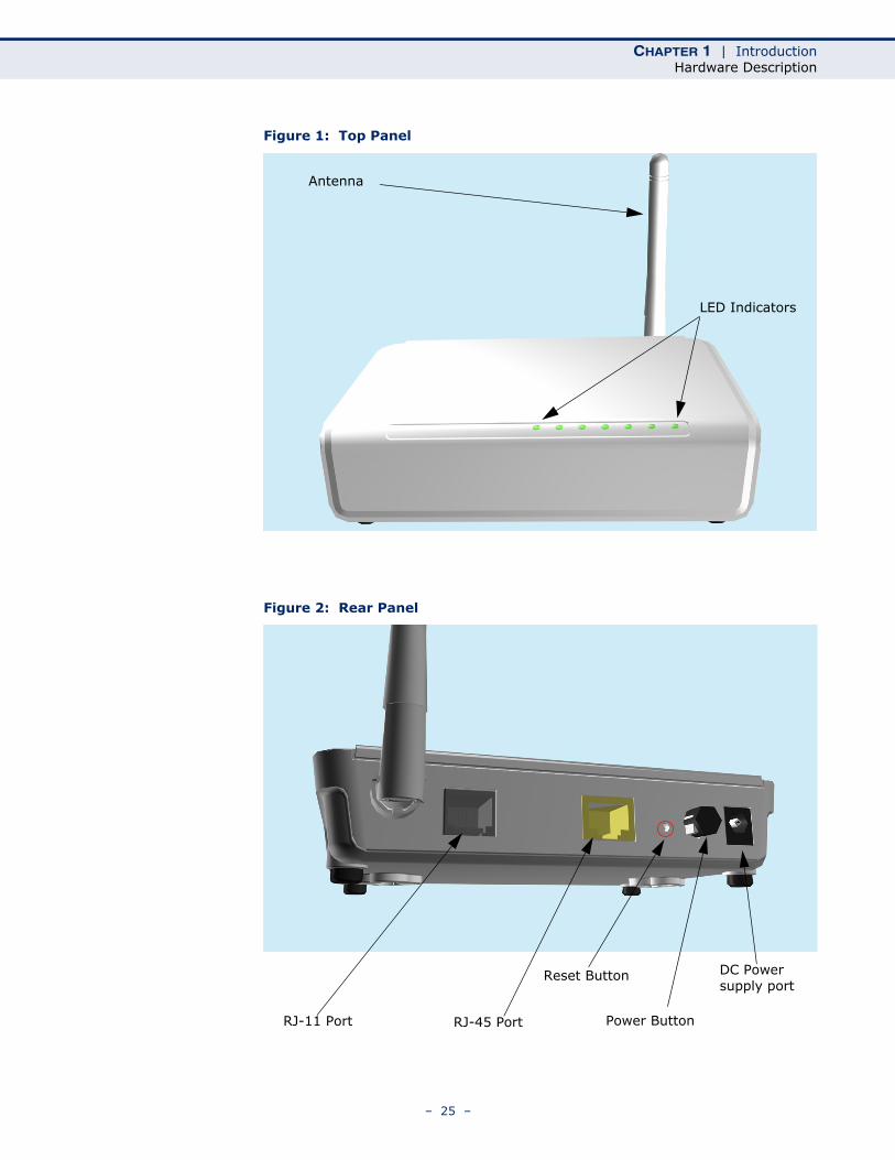
The Barricade Wireless Broadband Router, from herein refered to as ADSL Router, contains an integrated DSL modem and connects to the Internet or to a remote site using its RJ-11 WAN port. It connects directly to your PC or to a local area network using its RJ-45 Fast Ethernet LAN port or via a wireless network adapter.
Access speed to the Internet depends on your service type. Theoretically ADSL2+ provides up to 24 Mbps downstream and 3.5 Mbps upstream. However, this depends on the distance between your home and the central office (CO) of the service provider. Actual rates provided by specific broadband service providers may vary dramatically from these upper limits due to both distance and type of deployment of DSLAM equipment. Typically a modern domestic broadband connection can reach maximum download speeds dependent on your port capabilities and upload speeds usually set at a slower rate. This again is dependent on your service provider and what contract you sign with them.
Using the ADSL Router data passing between devices connected to your local area network can run at up to 100 Mbps over the Fast Ethernet ports and up to 54 Mbps over the built-in wireless network adapter.
The ADSL Router includes an LED display on the front panel for system power and port indications that simplifies installation and network troubleshooting.
– 24 –
CHAPTER 1 | IntroductionHardware Description
Figure 1: Top Panel
Figure 2: Rear Panel
LED Indicators
Antenna
RJ-11 Port RJ-45 Port
Reset Button
Power Button
DC Power supply port
– 25 –
CHAPTER 1 | IntroductionHardware Description
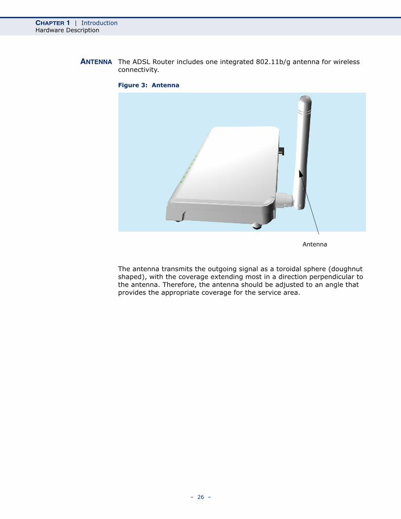
ANTENNA The ADSL Router includes one integrated 802.11b/g antenna for wireless connectivity.
Figure 3: Antenna
The antenna transmits the outgoing signal as a toroidal sphere (doughnut shaped), with the coverage extending most in a direction perpendicular to the antenna. Therefore, the antenna should be adjusted to an angle that provides the appropriate coverage for the service area.
Antenna
– 26 –
CHAPTER 1 | IntroductionHardware Description
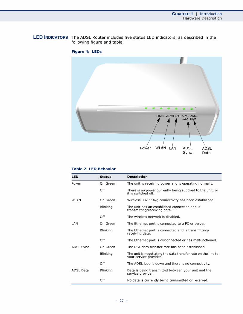
LED INDICATORS The ADSL Router includes five status LED indicators, as described in the following figure and table.
Figure 4: LEDs
Table 2: LED Behavior
LED Status Description
Power On Green The unit is receiving power and is operating normally.
Off There is no power currently being supplied to the unit, or it is switched off.
WLAN On Green Wireless 802.11b/g connectivity has been established.
Blinking The unit has an established connection and is transmitting/receiving data.
Off The wireless network is disabled.
LAN On Green The Ethernet port is connected to a PC or server.
Blinking The Ethernet port is connected and is transmitting/receiving data.
Off The Ethernet port is disconnected or has malfunctioned.
ADSL Sync On Green The DSL data transfer rate has been established.
Blinking The unit is negotiating the data transfer rate on the line to your service provider.
Off The ADSL loop is down and there is no connectivity.
ADSL Data Blinking Data is being transmitted between your unit and the service provider.
Off No data is currently being transmitted or received.
ADSLData
ADSLSync
LANWLANPower
– 27 –
CHAPTER 1 | IntroductionHardware Description
ETHERNET PORT The ADSL Router has one 100BASE-TX RJ-45 port that can be attached directly to 10BASE-T/100BASE-TX LAN segments.
This port supports automatic MDI/MDI-X operation, so you can use straight-through cables for all network connections to PCs, switches, or hubs.
POWER CONNECTORAND BUTTON
The ADSL Router has a power button. When the AC power adapter is attached and connected to a power source, you must depress the power button to power the unit.
The power adapter automatically adjusts to any voltage between 100~240 volts at 50 or 60 Hz, and supplies 12 volts DC power to the unit. No voltage range settings are required.
RESET BUTTON This button is used to restore the factory default configuration. If you hold down the button for 5 seconds or more, any configuration changes you may have made are removed, and the factory default configuration is restored to the access point.
– 28 –
2 INSTALLING THE ADSL ROUTER
This chapter describes how to install the ADSL Router.
SYSTEM REQUIREMENTS
You must meet the following minimum requirements:
◆ ADSL Internet service provider and modem with Ethernet connection.
◆ A 2.4GHz 802.11b/g wireless adapter installed on each PC. Alternatively an Ethernet adapter can be used.
◆ A web browser: Internet Explorer 5.5 or above, Netscape 4.7 or above, Mozilla Firefox 1.0 or above.
LOCATION SELECTION
Choose a proper place for the ADSL Router. In general, the best location is at the center of your wireless coverage area, within line of sight of all wireless devices. Try to place the ADSL Router in a position that can best cover its service area. For optimum performance, consider these guidelines:
◆ Mount the ADSL Router as high as possible above any obstructions in the coverage area.
◆ Avoid mounting next to or near building support columns or other obstructions that may cause reduced signal or null zones in parts of the coverage area.
◆ Mount away from any signal absorbing or reflecting structures (such as those containing metal).
The ADSL Router can be mounted on any horizontal surface, or a wall.
– 29 –
CHAPTER 2 | Installing the ADSL RouterMounting on a Horizontal Surface
MOUNTING ON A HORIZONTAL SURFACE
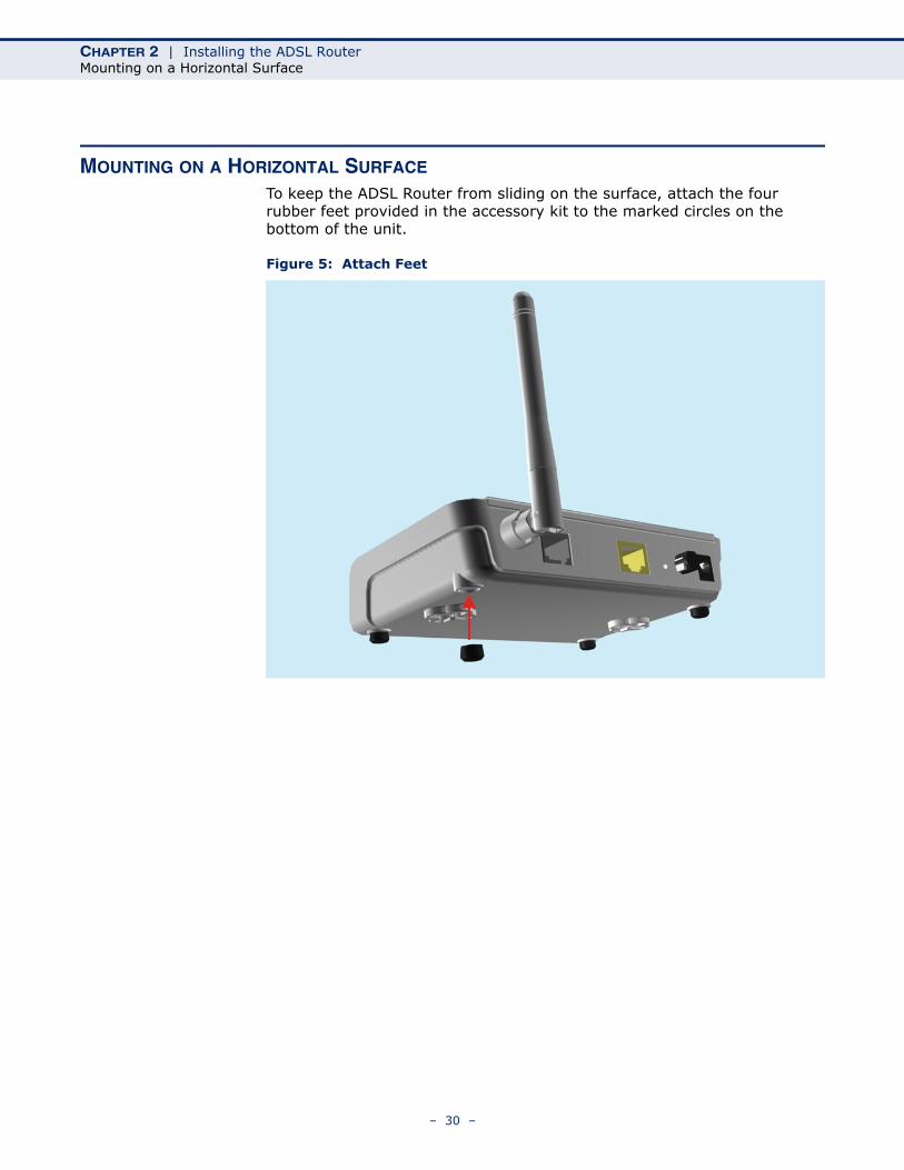
To keep the ADSL Router from sliding on the surface, attach the four rubber feet provided in the accessory kit to the marked circles on the bottom of the unit.
Figure 5: Attach Feet
– 30 –
CHAPTER 2 | Installing the ADSL RouterMounting on a Wall
MOUNTING ON A WALL
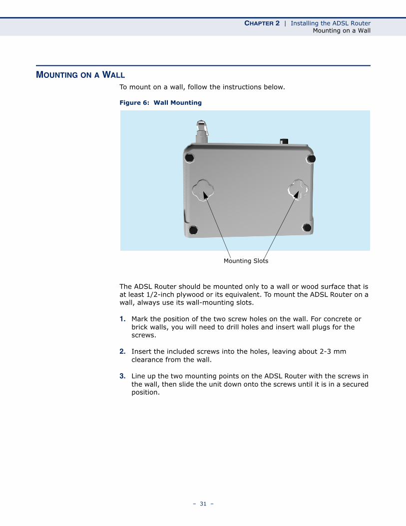
To mount on a wall, follow the instructions below.
Figure 6: Wall Mounting
The ADSL Router should be mounted only to a wall or wood surface that is at least 1/2-inch plywood or its equivalent. To mount the ADSL Router on a wall, always use its wall-mounting slots.
1. Mark the position of the two screw holes on the wall. For concrete or brick walls, you will need to drill holes and insert wall plugs for the screws.
2. Insert the included screws into the holes, leaving about 2-3 mm clearance from the wall.
3. Line up the two mounting points on the ADSL Router with the screws in the wall, then slide the unit down onto the screws until it is in a secured position.
Mounting Slots
– 31 –
CHAPTER 2 | Installing the ADSL RouterConnecting and Powering On
Figure 7: Wall Mounting Screws
CONNECTING AND POWERING ON
Connect the AC power adapter to the ADSL Router, and the power cord to an AC power outlet.
CAUTION: Use ONLY the power adapter supplied with this ADSL Router. Otherwise, the product may be damaged.
1. Observe the Power LED – When you power on the ADSL Router, verify that the Power indicator turns on, and that the other indicators start functioning as described under “LED Indicators” on page 27.
2. Connect the Ethernet Cable – The ADSL Router can be connected to a 10/100 Mbps Ethernet network through a device such as a hub or a switch. Connect your network to the RJ-45 port on the back panel with Category 5 or better UTP Ethernet cable. When the ADSL Router and the connected device are powered on, the Ethernet Link LED should turn on indicating a valid network connection.
NOTE: The RJ-45 port on the ADSL Router supports automatic MDI/MDI-X operation, so you can use straight-through cables for all network connections to PCs, switches, or hubs.
Mounting Screws
– 32 –

CHAPTER 2 | Installing the ADSL RouterConnecting and Powering On
3. Position the Antenna – The antenna emits a radiation pattern that is toroidal (doughnut shaped), with the coverage extending most in the direction perpendicular to the antenna. Therefore, the antenna should be oriented so that the radio coverage pattern fills the intended horizontal space. For example, if the ADSL Router is mounted on a horizontal surface, the antenna should be positioned pointing vertically up to provide optimum coverage.
– 33 –

CHAPTER 2 | Installing the ADSL RouterConnecting and Powering On
– 34 –
3 INITIAL CONFIGURATION
The ADSL Router offers a user-friendly web-based management interface for the configuration of all the unit’s features. Any PC directly attached to the unit can access the management interface using a web browser, such as Internet Explorer (version 6.0 or above).
ISP SETTINGS
If you are not sure of your connection method, please contact your Internet Service Provider. There are several connection types to choose from: Static IP, DHCP, PPPoE, PPPoA, PPTP and L2TP.
NOTE: If using the PPPoE option, you will need to remove or disable any PPPoE client software on your computers.
CONNECTING TO THE LOGIN PAGE
It is recommended to make initial configuration changes by connecting a PC directly to the ADSL Router’s LAN port. The ADSL Router has a default IP address of 192.168.2.1 and a subnet mask of 255.255.255.0. You must set your PC IP address to be on the same subnet as the ADSL Router (that is, the PC and ADSL Router addresses must both start 192.168.2.x).
To access the ADSL Router’s management interface, follow these steps:
1. Use your web browser to connect to the management interface using the default IP address of 192.168.2.1.
2. Log into the interface by entering the default username “admin” and password “smcadmin,” then click Login.
NOTE: It is strongly recommended to change the default user name and password the first time you access the web interface. For information on changing user names and passwords, See “Channel Configuration” on page 59.
– 35 –
CHAPTER 3 | Initial ConfigurationHome Page and Main Menu
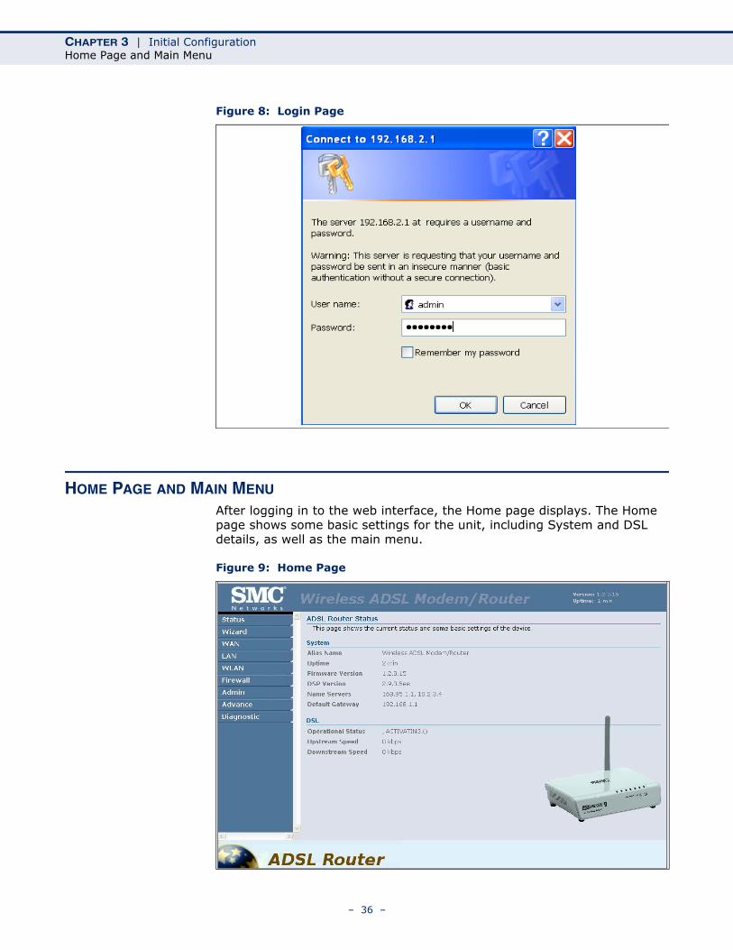
Figure 8: Login Page
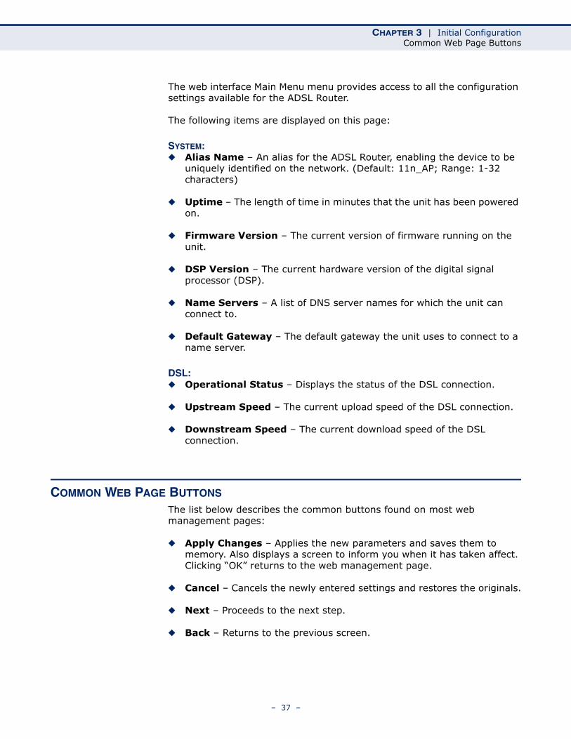
HOME PAGE AND MAIN MENU
After logging in to the web interface, the Home page displays. The Home page shows some basic settings for the unit, including System and DSL details, as well as the main menu.
Figure 9: Home Page
– 36 –
CHAPTER 3 | Initial ConfigurationCommon Web Page Buttons
The web interface Main Menu menu provides access to all the configuration settings available for the ADSL Router.
The following items are displayed on this page:
SYSTEM:◆ Alias Name – An alias for the ADSL Router, enabling the device to be
uniquely identified on the network. (Default: 11n_AP; Range: 1-32 characters)
◆ Uptime – The length of time in minutes that the unit has been powered on.
◆ Firmware Version – The current version of firmware running on the unit.
◆ DSP Version – The current hardware version of the digital signal processor (DSP).
◆ Name Servers – A list of DNS server names for which the unit can connect to.
◆ Default Gateway – The default gateway the unit uses to connect to a name server.
DSL:◆ Operational Status – Displays the status of the DSL connection.
◆ Upstream Speed – The current upload speed of the DSL connection.
◆ Downstream Speed – The current download speed of the DSL connection.
COMMON WEB PAGE BUTTONS
The list below describes the common buttons found on most web management pages:
◆ Apply Changes – Applies the new parameters and saves them to memory. Also displays a screen to inform you when it has taken affect. Clicking “OK” returns to the web management page.
◆ Cancel – Cancels the newly entered settings and restores the originals.
◆ Next – Proceeds to the next step.
◆ Back – Returns to the previous screen.
– 37 –
CHAPTER 3 | Initial ConfigurationWizard
WIZARD
The Wizard menu is designed to help you configure the basic settings required to get the ADSL Router up and running. Click “Wizard” in the main menu to get started.
STEP 1 - INTERNETCONNECTION
SETTINGS
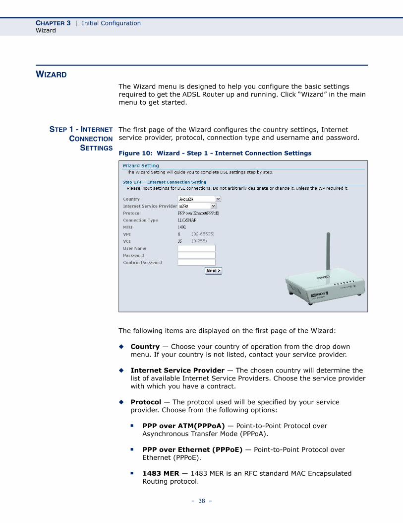
The first page of the Wizard configures the country settings, Internet service provider, protocol, connection type and username and password.
Figure 10: Wizard - Step 1 - Internet Connection Settings
The following items are displayed on the first page of the Wizard:
◆ Country — Choose your country of operation from the drop down menu. If your country is not listed, contact your service provider.
◆ Internet Service Provider — The chosen country will determine the list of available Internet Service Providers. Choose the service provider with which you have a contract.
◆ Protocol — The protocol used will be specified by your service provider. Choose from the following options:
■ PPP over ATM(PPPoA) — Point-to-Point Protocol over Asynchronous Transfer Mode (PPPoA).
■ PPP over Ethernet (PPPoE) — Point-to-Point Protocol over Ethernet (PPPoE).
■ 1483 MER — 1483 MER is an RFC standard MAC Encapsulated Routing protocol.
– 38 –
CHAPTER 3 | Initial ConfigurationWizard
■ 1483 Router (IPoA) — Dynamic IP over ATM (IPoA).
■ 1483 Bridged — The Bridged RFC 1483 Encapsulated Traffic over ATM feature allows you to send bridged RFC 1483 encapsulated packets over ATM switched virtual circuits (SVCs).
◆ Connection Type — Your connection type will also be specified by your service provider. Choose from the following options:
■ VC-Mux — Virtual circuit multiplexing (VC-Mux).
■ LLC/SNAP — Logical Link Control (LLC).
◆ MTU — This is a preset field and does not require configuration. For more information see “Current ATM VC Table” on page 64
◆ VPI — This is a preset field and does not require configuration. For more information see “Channel Configuration” on page 59.
◆ VCI — This is a preset field and does not require configuration. For more information see “Channel Configuration” on page 59.
◆ Username — Enter the username provided by your service provider.
◆ Password — Enter the password provided by your service provider.
◆ Confirm Password — Re-enter your password.
◆ Next — Proceeds to the next step.
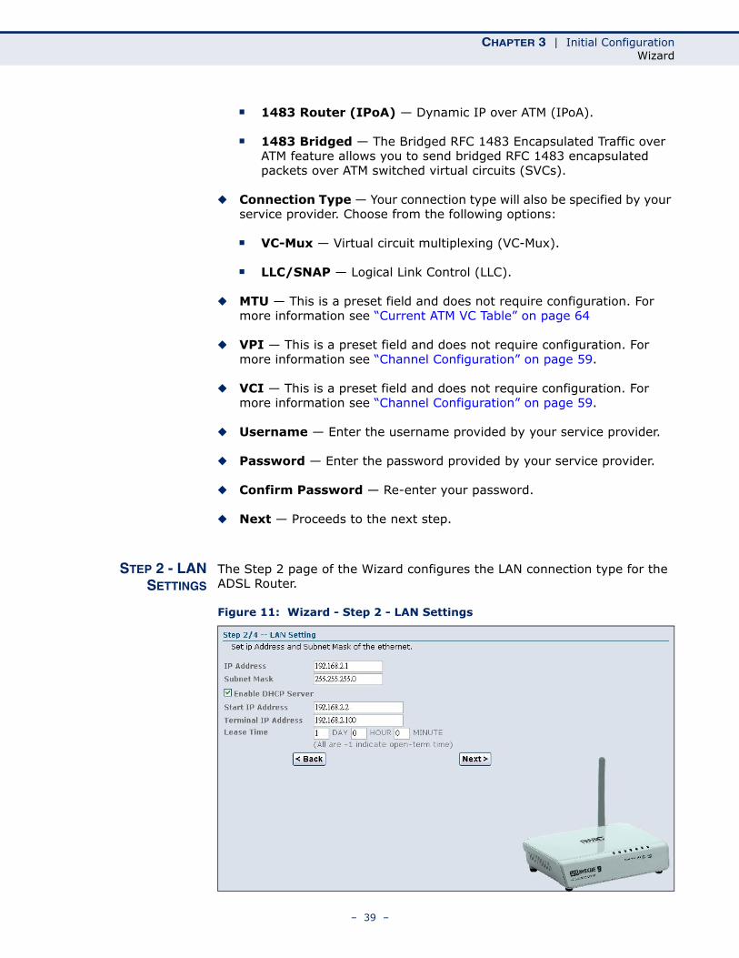
STEP 2 - LANSETTINGS
The Step 2 page of the Wizard configures the LAN connection type for the ADSL Router.
Figure 11: Wizard - Step 2 - LAN Settings
– 39 –
CHAPTER 3 | Initial ConfigurationWizard
The following items are displayed on this page:
◆ IP Address — Specifies an IP address for management of the ADSL Router. Valid IP addresses consist of four decimal numbers, 0 to 255, separated by periods. (Default: 192.168.2.1.)
◆ Subnet Mask — Indicates the local subnet mask. Select the desired mask from the drop down menu. (Default: 255.255.255.0)
◆ Enable the secondary LAN IP — Enables/disables dual LAN IP addresses as a fallback measure.
◆ Enable DHCP Server — Enables/disables DHCP on the ADSL Router. (Default: disabled)
◆ Start IP Address — Specifies the start DHCP IP address. Valid IP addresses consist of four decimal numbers, 0 to 255, separated by periods. (Default: 192.168.2.1.)
◆ Terminal IP Address — Specifies the end DHCP IP address.
◆ Lease Time — When DHCP sends configuration information to a client, the information is sent with a lease time. This is the length of time that the client can use the IP address it has been assigned. The duration of the lease time can be changed according to your specific requirement.
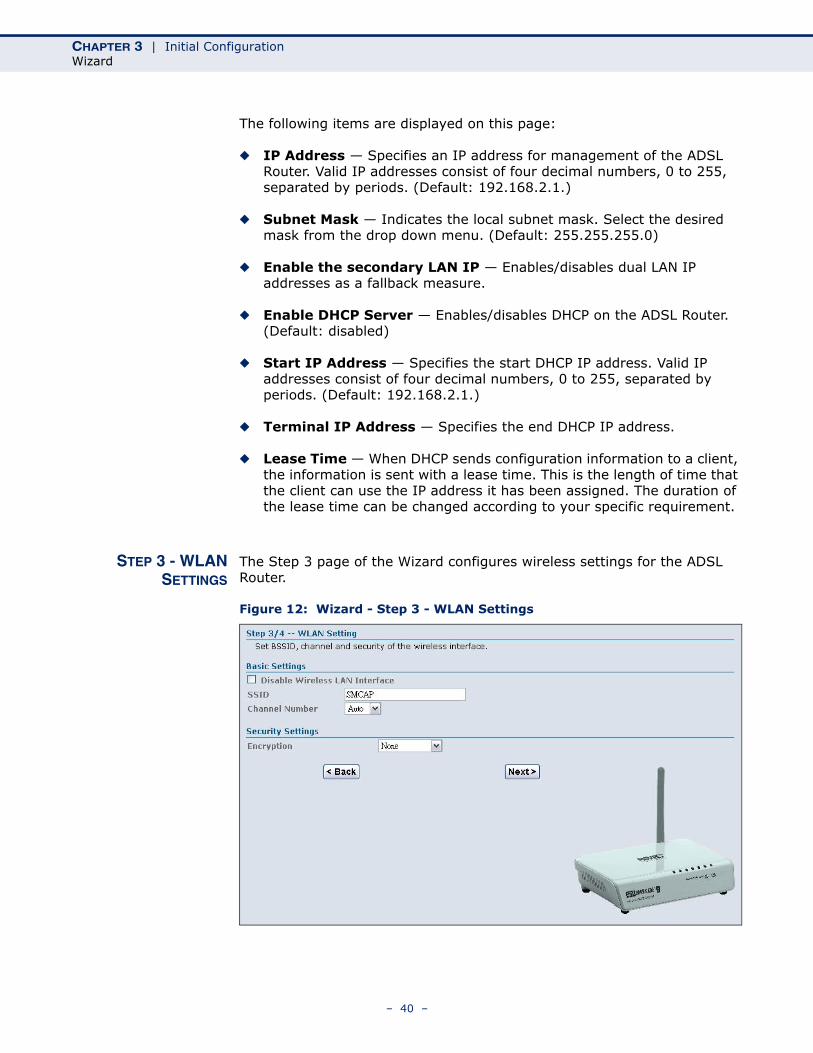
STEP 3 - WLANSETTINGS
The Step 3 page of the Wizard configures wireless settings for the ADSL Router.
Figure 12: Wizard - Step 3 - WLAN Settings
– 40 –
CHAPTER 3 | Initial ConfigurationWizard
The following items are displayed on this page:
BASIC SETTINGS◆ Disable Wireless LAN Interface — Enables/disables the wireless
802.11b/g interface.
◆ SSID — Specifies an SSID (service set identifier) which must be the same as that on all wireless clients that wish to associate with the unit.
◆ Channel Number — Specifies the radio channel number which must be the same as that on all wireless clients that wish to associate with the unit. The ADSL Router is set to automatically detect channel settings of wireless devices. (Default: Auto; Range: 1~11)
SECURITY SETTINGSThis section configures security settings to protect from intruders accessing your network.
◆ Encryption — Specifies the security used to protect your wireless network. (Default: None)
■ None: Allows any wireless client within range to associate with the ADSL/Router.
■ WEP: Provides a basic level of security using static shared keys that are distributed to all clients. Be sure to configure at least one static key. Alternatively, enable 802.1X authentication to dynamically create and distribute keys from a RADIUS server.
■ WPA(TKIP): Wi-Fi Protected Access (WPA) using either a static pre-shared key, or 802.1X authentication through a RADIUS server.
■ WPA2(AES): WPA2 using either a static pre-shared key, or 802.1X authentication through a RADIUS server.
■ WPA2 Mixed: WPA and WPA2 using either a static pre-shared key, or 802.1X authentication through a RADIUS server.
– 41 –
CHAPTER 3 | Initial ConfigurationWizard
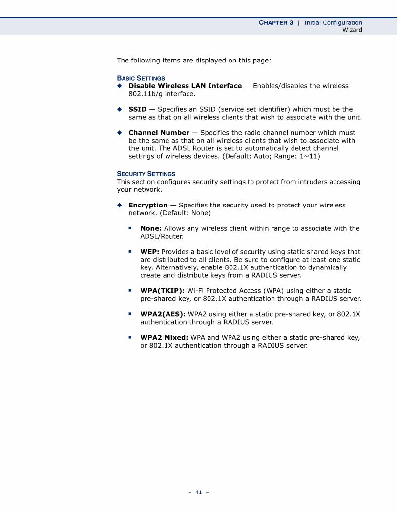
STEP 4 - APPLYCHANGES
The following pages details the final step in the setup Wizard.
Figure 13: Wizard Settings Summary
The following items are displayed on this page:
WAN SETTINGDetails the WAN port settings chosen including VPI/VCI and connection type.
LAN SETTINGDetails the LAN port settings chosen including LAN IP adress and DHCP server.
WLAN SETTINGDetails the wireless radio settings chosen including status, SSID, radio channel and security method.
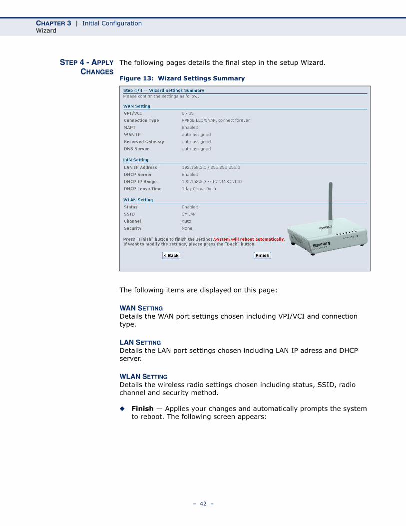
◆ Finish — Applies your changes and automatically prompts the system to reboot. The following screen appears:
– 42 –
CHAPTER 3 | Initial ConfigurationWizard
Figure 14: System Restarting
– 43 –

CHAPTER 3 | Initial ConfigurationWizard
– 44 –
SECTION II
WEB CONFIGURATION
This section provides details on configuring the ADSL Router using the web browser interface.
This section includes these chapters:
◆ “Status Information” on page 47
◆ “WAN Configuration” on page 59
◆ “LAN Configuration” on page 69
◆ “WLAN Configuration” on page 75
◆ “Firewall Configuration” on page 87
◆ “Administration Settings” on page 101
◆ “Advanced Configuration” on page 111
◆ “Diagnostics” on page 127
– 45 –

SECTION | Web Configuration
– 46 –
4 STATUS INFORMATION
The Status menu displays information on the current system configuration, the wireless interface, the system statistics, bridging information and routing information.
Status Information includes the following sections:
◆ “System” on page 48
◆ “WAN” on page 49
◆ “LAN” on page 50
◆ “WLAN” on page 51
◆ “Traffic Statistics” on page 52
◆ “DSL Statistics” on page 53
◆ “ARP Table” on page 55
◆ “Bridging Table” on page 56
◆ “Routing Table” on page 57
– 47 –
CHAPTER 4 | Status InformationSystem
SYSTEM
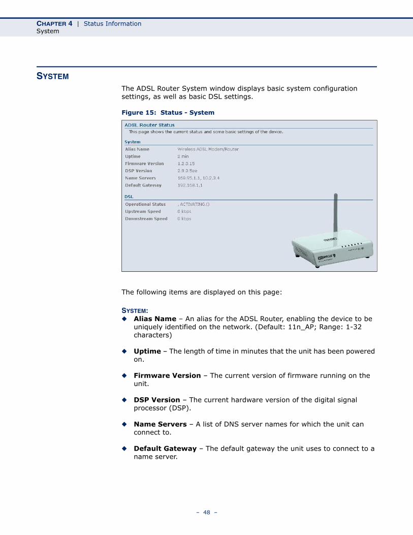
The ADSL Router System window displays basic system configuration settings, as well as basic DSL settings.
Figure 15: Status - System
The following items are displayed on this page:
SYSTEM:◆ Alias Name – An alias for the ADSL Router, enabling the device to be
uniquely identified on the network. (Default: 11n_AP; Range: 1-32 characters)
◆ Uptime – The length of time in minutes that the unit has been powered on.
◆ Firmware Version – The current version of firmware running on the unit.
◆ DSP Version – The current hardware version of the digital signal processor (DSP).
◆ Name Servers – A list of DNS server names for which the unit can connect to.
◆ Default Gateway – The default gateway the unit uses to connect to a name server.
– 48 –
CHAPTER 4 | Status InformationWAN
DSL:◆ Operational Status – Displays the status of the DSL connection.
◆ Upstream Speed – The current upload speed of the DSL connection.
◆ Downstream Speed – The current download speed of the DSL connection.
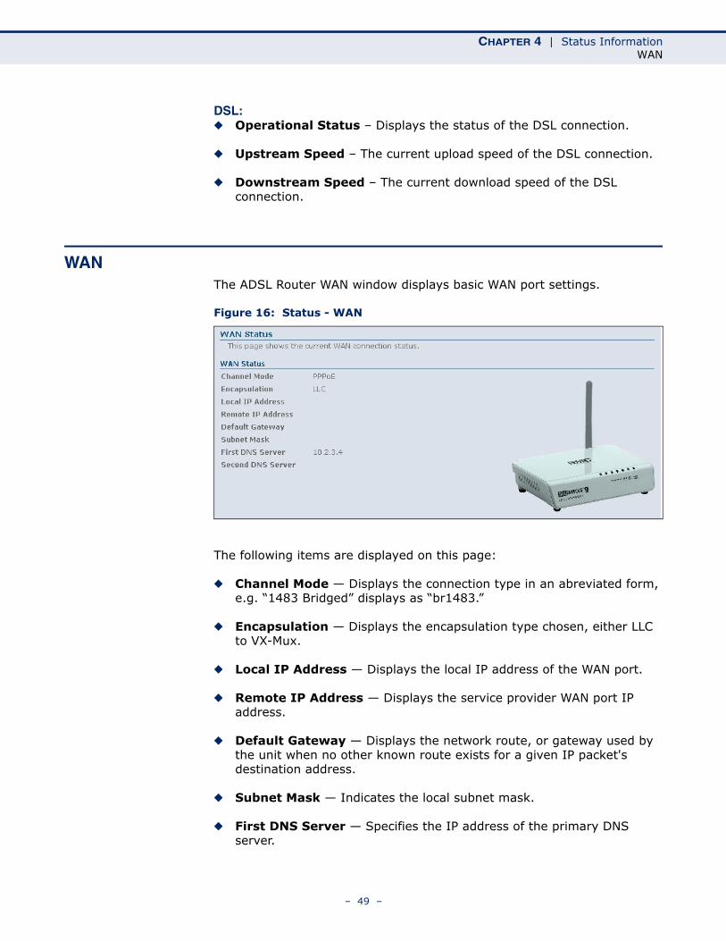
WANThe ADSL Router WAN window displays basic WAN port settings.
Figure 16: Status - WAN
The following items are displayed on this page:
◆ Channel Mode — Displays the connection type in an abreviated form, e.g. “1483 Bridged” displays as “br1483.”
◆ Encapsulation — Displays the encapsulation type chosen, either LLC to VX-Mux.
◆ Local IP Address — Displays the local IP address of the WAN port.
◆ Remote IP Address — Displays the service provider WAN port IP address.
◆ Default Gateway — Displays the network route, or gateway used by the unit when no other known route exists for a given IP packet's destination address.
◆ Subnet Mask — Indicates the local subnet mask.
◆ First DNS Server — Specifies the IP address of the primary DNS server.
– 49 –
CHAPTER 4 | Status InformationLAN
◆ Second DNS Server — Specifies the IP address of the secondary DNS server.
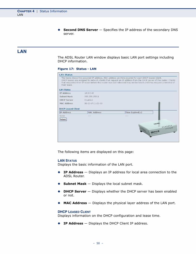
LANThe ADSL Router LAN window displays basic LAN port settings including DHCP information.
Figure 17: Status - LAN
The following items are displayed on this page:
LAN STATUSDisplays the basic information of the LAN port.
◆ IP Address — Displays an IP address for local area connection to the ADSL Router.
◆ Subnet Mask — Displays the local subnet mask.
◆ DHCP Server — Displays whether the DHCP server has been enabled or not.
◆ MAC Address — Displays the physical layer address of the LAN port.
DHCP LEASED CLIENTDisplays information on the DHCP configuration and lease time.
◆ IP Address — Displays the DHCP Client IP address.
– 50 –
CHAPTER 4 | Status InformationWLAN
◆ MAC Address — Displays the physical layer address of the DHCP Client.
◆ Time Expired (s) — Displays the duration of the lease time.
◆ Refresh — Updates the information for the entire screen should any changes have occured.
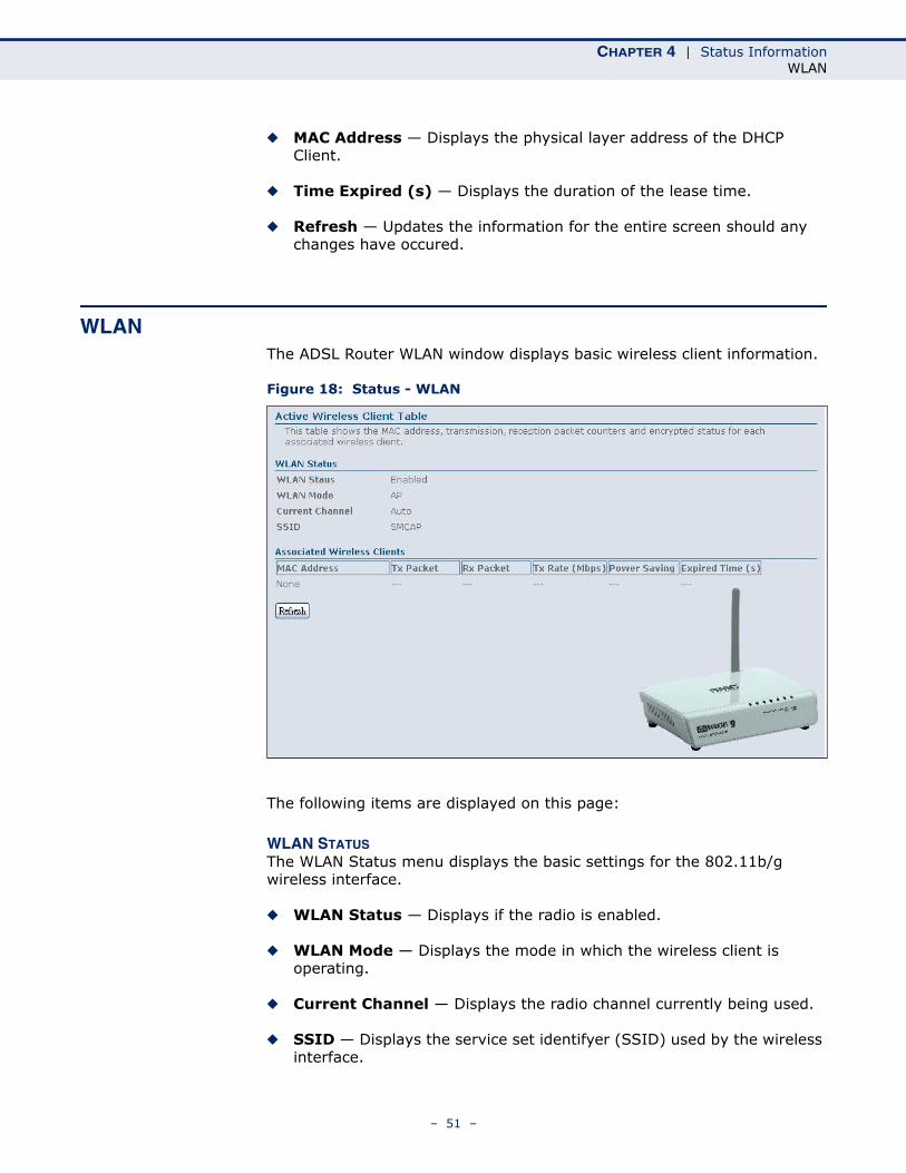
WLANThe ADSL Router WLAN window displays basic wireless client information.
Figure 18: Status - WLAN
The following items are displayed on this page:
WLAN STATUSThe WLAN Status menu displays the basic settings for the 802.11b/g wireless interface.
◆ WLAN Status — Displays if the radio is enabled.
◆ WLAN Mode — Displays the mode in which the wireless client is operating.
◆ Current Channel — Displays the radio channel currently being used.
◆ SSID — Displays the service set identifyer (SSID) used by the wireless interface.
– 51 –
CHAPTER 4 | Status InformationTraffic Statistics
ASSOCIATED WIRELESS CLIENTSThe Associated Wireless Clients menu displays information on wireless clients that have attached to the ADSL Router.
◆ MAC Address — Displays the MAC address of the associated wireless client.
◆ Tx Packet — Displays the total number of packets sent by the wireless client to the ADSL Router.
◆ Rx Packet — Displays the total number of packets received by the wireless client from the ADLS/Router.
◆ Tx Rate (Mbps) — Displays the tranmission rate of the wireless client in megabits per second (Mbps).
◆ Power Saving — Displays if power saving mode has been enabled on the wireless client.
◆ Expired Time (s) — Displays if the time after which the wireless client will lose connectivity with the ADSL Router.
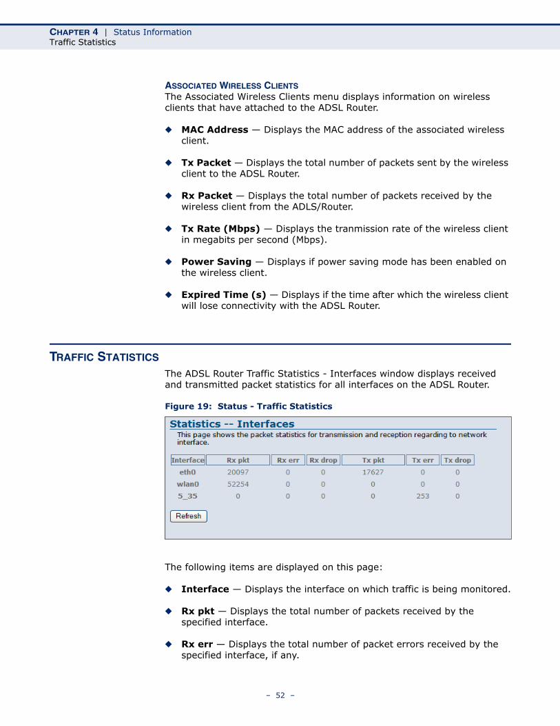
TRAFFIC STATISTICS
The ADSL Router Traffic Statistics - Interfaces window displays received and transmitted packet statistics for all interfaces on the ADSL Router.
Figure 19: Status - Traffic Statistics
The following items are displayed on this page:
◆ Interface — Displays the interface on which traffic is being monitored.
◆ Rx pkt — Displays the total number of packets received by the specified interface.
◆ Rx err — Displays the total number of packet errors received by the specified interface, if any.
– 52 –
CHAPTER 4 | Status InformationDSL Statistics
◆ Rx drop — Displays the total number of received packets dropped by the specified interface.
◆ Tx pkt — Displays the total number of packets transmitted by the specifed interface.
◆ Tx err — Displays the total number of packet errors occured during transmission by the specified interface.
◆ Tx drop — Displays the total number of packets transmitted but dropped by the specified interface.
◆ Refresh — Updates the statistical table for all interfaces.
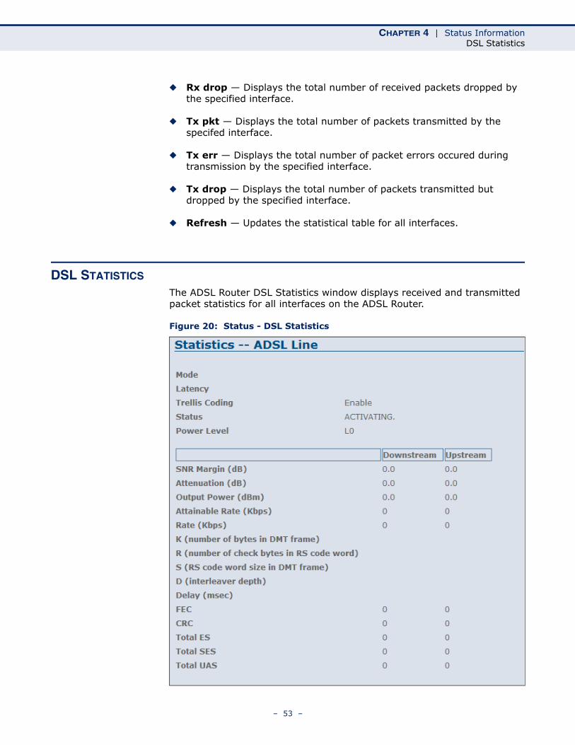
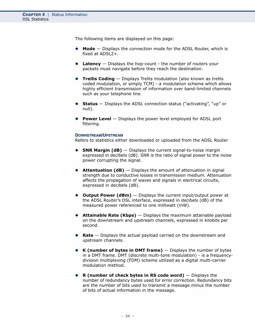
DSL STATISTICS
The ADSL Router DSL Statistics window displays received and transmitted packet statistics for all interfaces on the ADSL Router.
Figure 20: Status - DSL Statistics
– 53 –
CHAPTER 4 | Status InformationDSL Statistics
The following items are displayed on this page:
◆ Mode — Displays the connection mode for the ADSL Router, which is fixed at ADSL2+.
◆ Latency — Displays the hop-count - the number of routers your packets must navigate before they reach the destination.
◆ Trellis Coding — Displays Trellis modulation (also known as trellis coded modulation, or simply TCM) - a modulation scheme which allows highly efficient transmission of information over band-limited channels such as your telephone line.
◆ Status — Displays the ADSL connection status (“activating”, “up” or null).
◆ Power Level — Displays the power level employed for ADSL port filtering.
DOWNSTREAM/UPSTREAMRefers to statistics either downloaded or uploaded from the ADSL Router
◆ SNR Margin (dB) — Displays the current signal-to-noise margin expressed in decibels (dB). SNR is the ratio of signal power to the noise power corrupting the signal.
◆ Attentuation (dB) — Displays the amount of attenuation in signal strength due to conductive losses in transmission medium. Attenuation affects the propagation of waves and signals in electrical circuits, expressed in decibels (dB).
◆ Output Power (dBm) — Displays the current input/output power at the ADSL Router’s DSL interface, expressed in decibels (dB) of the measured power referenced to one milliwatt (mW).
◆ Attainable Rate (Kbps) — Displays the maximum attainable payload on the downstream and upstream channels, expressed in kilobits per second.
◆ Rate — Displays the actual payload carried on the downstream and upstream channels.
◆ K (number of bytes in DMT frame) — Displays the number of bytes in a DMT frame. DMT (discrete multi-tone modulation) - is a frequency-division multiplexing (FDM) scheme utilized as a digital multi-carrier modulation method.
◆ R (number of check bytes in RS code word) — Displays the number of redundancy bytes used for error correction. Redundancy bits are the number of bits used to transmit a message minus the number of bits of actual information in the message.
– 54 –
CHAPTER 4 | Status InformationARP Table
◆ S (RS code word size in DMT farme) — Displays the number of valid data symbols included by the RS code word in the DMT frame.
◆ D (interleaver depth) — Displays the actual depth of the interleaver used in the latency path in which the bearer channel is transported. Interleavers arrange data in a non-contiguous way in order to increase performance.
◆ Delay (nsec) — Displays interleave delay in nano-seconds (nsec). Interleave delay applies only to the interleave (slow) channel and defines the mapping (relative spacing) between subsequent input bytes at the interleaver input and their placement in the bit stream at the interleaver output.
◆ FEC — Displays forward error correction (FEC), a system of error control for data transmission, whereby the sender adds redundant data to its messages, also known as an error correction code.
◆ CRC — Displays the CRC (cyclic redunancy check) - a type of function that takes as input a data stream of any length, and produces as output a value of a certain space, commonly a 32-bit integer.
◆ Total ES — Displays the total error seconds, the number of second intervals during which there was one or more CRC anomalies, or one or more Loss of Signal (LOS) or Loss of Framing (LOF) defects.
◆ Total SES — Displays the total severly errored seconds. The number of second intervals containing 18 or more CRC-8 anomalies, one or more Loss of Signal (LOS) defects, one or more Severely Errored Frame (SEF) defects, or one or more Loss of Power (LPR) defects.
◆ Total UAS — Displays the total unavailable errored seconds, the number of seconds during which the ADSL transceiver is powered up but not available.
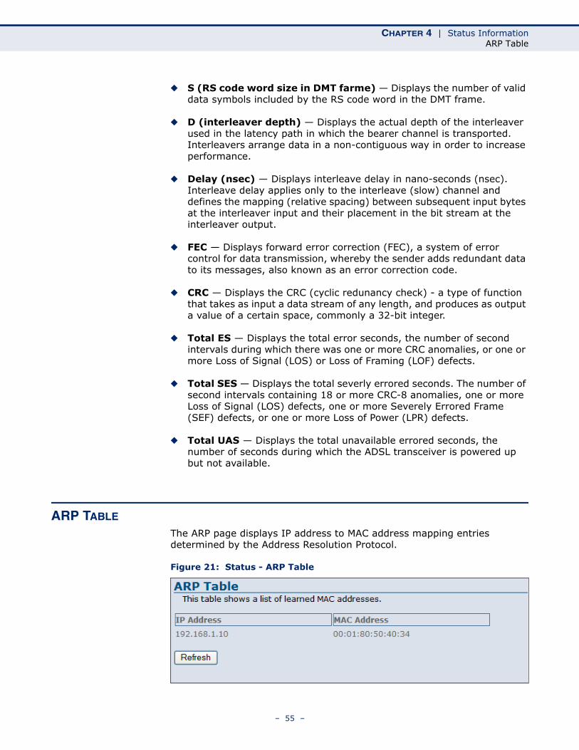
ARP TABLE
The ARP page displays IP address to MAC address mapping entries determined by the Address Resolution Protocol.
Figure 21: Status - ARP Table
– 55 –
CHAPTER 4 | Status InformationBridging Table
The following items are displayed on this page:
◆ IP Address — IP address of a local entry in the cache.
◆ MAC Address — MAC address mapped to the corresponding IP address.
◆ Refresh — Sends a request to update the current parameters.
BRIDGING TABLE
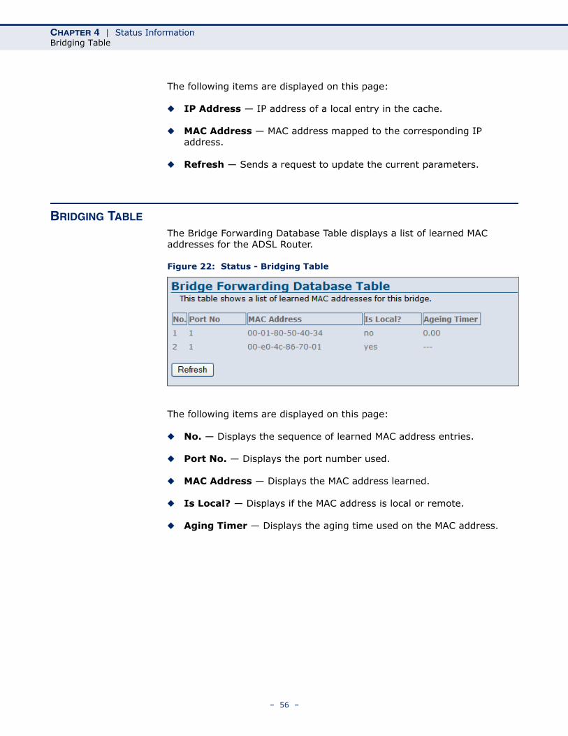
The Bridge Forwarding Database Table displays a list of learned MAC addresses for the ADSL Router.
Figure 22: Status - Bridging Table
The following items are displayed on this page:
◆ No. — Displays the sequence of learned MAC address entries.
◆ Port No. — Displays the port number used.
◆ MAC Address — Displays the MAC address learned.
◆ Is Local? — Displays if the MAC address is local or remote.
◆ Aging Timer — Displays the aging time used on the MAC address.
– 56 –
CHAPTER 4 | Status InformationRouting Table
ROUTING TABLE
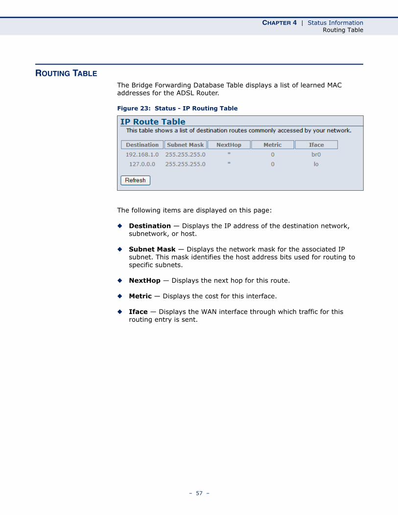
The Bridge Forwarding Database Table displays a list of learned MAC addresses for the ADSL Router.
Figure 23: Status - IP Routing Table
The following items are displayed on this page:
◆ Destination — Displays the IP address of the destination network, subnetwork, or host.
◆ Subnet Mask — Displays the network mask for the associated IP subnet. This mask identifies the host address bits used for routing to specific subnets.
◆ NextHop — Displays the next hop for this route.
◆ Metric — Displays the cost for this interface.
◆ Iface — Displays the WAN interface through which traffic for this routing entry is sent.
– 57 –

CHAPTER 4 | Status InformationRouting Table
– 58 –
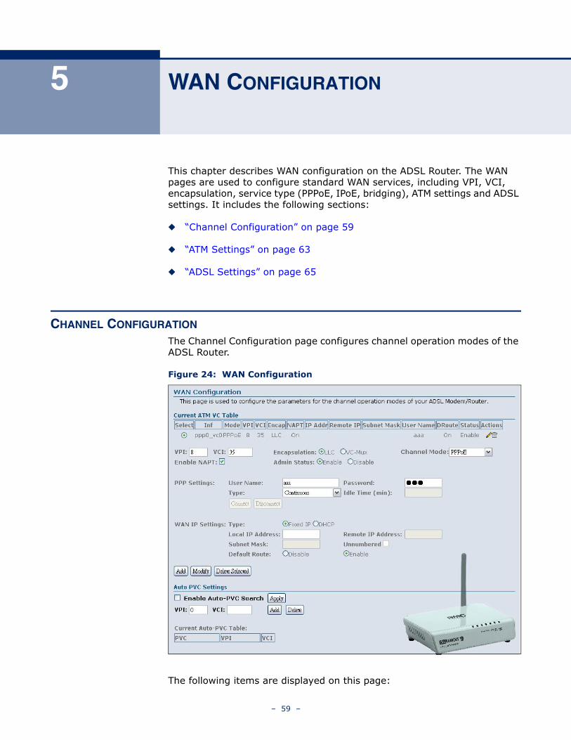
5 WAN CONFIGURATION
This chapter describes WAN configuration on the ADSL Router. The WAN pages are used to configure standard WAN services, including VPI, VCI, encapsulation, service type (PPPoE, IPoE, bridging), ATM settings and ADSL settings. It includes the following sections:
◆ “Channel Configuration” on page 59
◆ “ATM Settings” on page 63
◆ “ADSL Settings” on page 65
CHANNEL CONFIGURATION
The Channel Configuration page configures channel operation modes of the ADSL Router.
Figure 24: WAN Configuration
The following items are displayed on this page:
– 59 –
CHAPTER 5 | WAN ConfigurationChannel Configuration
CURRENT ATM VCTABLE
The Current ATM VC Table is a display only table of the configured parameters used to communincate with the remote ATM switch.
◆ Select — Selects the configured connection.
◆ Inf — Displays a virtual interface.
◆ Mode — Displays the channel mode employed by the link.
◆ VPI — Displays the virtual path identifyer (VPI) of the link.
◆ VCI — Displays the virtual vircuit identifyer (VCI) of the link.
◆ Encapt — Displays the encapsulation used.
◆ NAPT — Displays the network address port translation (NAPT).
◆ IP Addr — Displays the IP address of the link.
◆ Remote IP — Displays the remote IP address of the link.
◆ Subnet Mask — Displays the subnet mask.
◆ User Name — Displays the user name.
◆ DRoute — Dipslays if a default route (DRoute) has been enabled.
◆ Status — Displays if the link is enabled or disabled.
◆ Actions — Gives the options to edit the link information using the pencil icon, or delete the link using the trashcan icon.
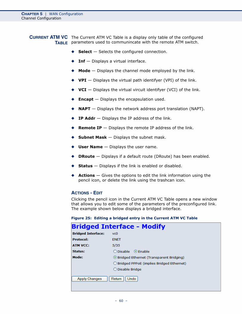
ACTIONS - EDIT
Clicking the pencil icon in the Current ATM VC Table opens a new window that allows you to edit some of the parameters of the preconfigured link. The example shown below displays a bridged interface.
Figure 25: Editing a bridged entry in the Current ATM VC Table
– 60 –
CHAPTER 5 | WAN ConfigurationChannel Configuration
The following items are displayed on this page:
◆ Bridged Interface — Displays a virtual interface.
◆ Protocol — Displays the protocol used for transmission of data packets.
◆ ATM VCC — Displays the virtual channel connection (VCC) to the remote ATM switch formed by the combination of the VCI and VPI.
◆ Status — Allows the user to enable or disable the link.
◆ Mode — Allows the user to select the connection protocol, such as PPPoE, or disable it.
◆ Apply Changes — Applies the user specified changes.
◆ Return — Returns to the previous creen without making changes.
◆ Undo — Undoes any changes to the connection made by the user and restores the originals.
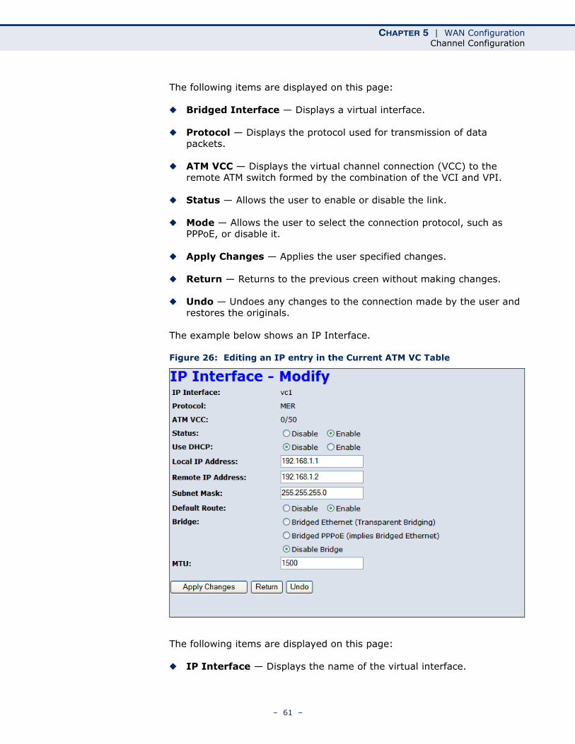
The example below shows an IP Interface.
Figure 26: Editing an IP entry in the Current ATM VC Table
The following items are displayed on this page:
◆ IP Interface — Displays the name of the virtual interface.
– 61 –
CHAPTER 5 | WAN ConfigurationChannel Configuration
◆ Protocol — Displays the protocol used for transmission of data packets.
◆ ATM VCC — Displays the virtual channel connection (VCC) to the remote ATM switch formed by the combination of the VCI and VPI.
◆ Status — Allows the user to enable or disable the link.
◆ Use DHCP — Allows the user to disable fixed IP address and use DHCP.
◆ Local IP Address — Specifies a local IP address.
◆ Remote IP Address — Specifies a remote IP address on the ATM server.
◆ Subnet Mask — Specifies a subnet mask.
◆ Default Route — Enables/disables a default route.
◆ Bridge — Allows the user to select the connection protocol, such as PPPoE, or disable it.
◆ MTU — Sets the maximum transmission unit (MTU), the size of the largest packet that a network protocol can transmit.
◆ Apply Changes — Applies the user specified changes.
◆ Return — Returns to the previous creen without making changes.
◆ Undo — Undoes any changes to the connection made by the user and restores the originals.
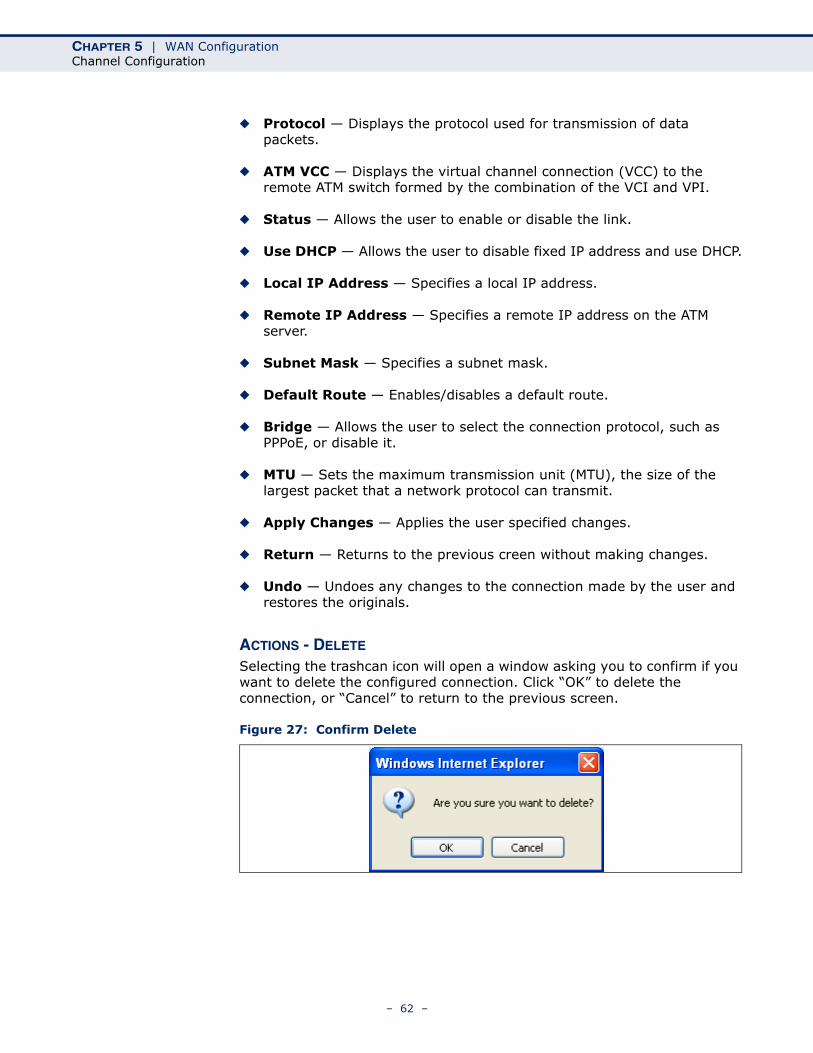
ACTIONS - DELETE
Selecting the trashcan icon will open a window asking you to confirm if you want to delete the configured connection. Click “OK” to delete the connection, or “Cancel” to return to the previous screen.
Figure 27: Confirm Delete
– 62 –
CHAPTER 5 | WAN ConfigurationATM Settings
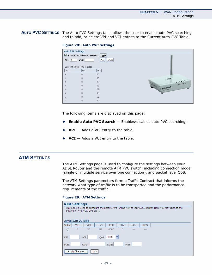
AUTO PVC SETTINGS The Auto PVC Settings table allows the user to enable auto PVC searching and to add, or delete VPI and VCI entries to the Current Auto-PVC Table.
Figure 28: Auto PVC Settings
The following items are displayed on this page:
◆ Enable Auto PVC Search — Enables/disables auto PVC searching.
◆ VPI — Adds a VPI entry to the table.
◆ VCI — Adds a VCI entry to the table.
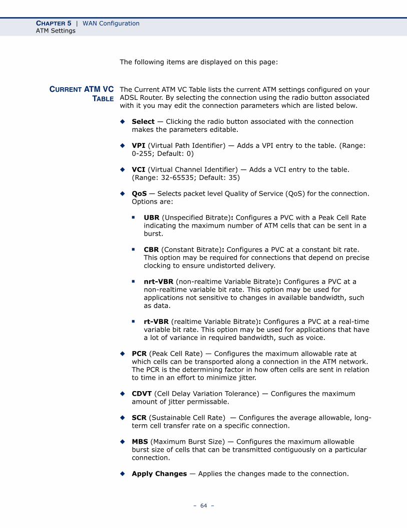
ATM SETTINGS
The ATM Settings page is used to configure the settings between your ADSL Router and the remote ATM PVC switch, including connection mode (single or multiple service over one connection), and packet level QoS.
The ATM Settings parameters form a Traffic Contract that informs the network what type of traffic is to be transported and the performance requirements of the traffic.
Figure 29: ATM Settings
– 63 –
CHAPTER 5 | WAN ConfigurationATM Settings
The following items are displayed on this page:
CURRENT ATM VCTABLE
The Current ATM VC Table lists the current ATM settings configured on your ADSL Router. By selecting the connection using the radio button associated with it you may edit the connection parameters which are listed below.
◆ Select — Clicking the radio button associated with the connection makes the parameters editable.
◆ VPI (Virtual Path Identifier) — Adds a VPI entry to the table. (Range: 0-255; Default: 0)
◆ VCI (Virtual Channel Identifier) — Adds a VCI entry to the table. (Range: 32-65535; Default: 35)
◆ QoS — Selects packet level Quality of Service (QoS) for the connection. Options are:
■ UBR (Unspecified Bitrate): Configures a PVC with a Peak Cell Rate indicating the maximum number of ATM cells that can be sent in a burst.
■ CBR (Constant Bitrate): Configures a PVC at a constant bit rate. This option may be required for connections that depend on precise clocking to ensure undistorted delivery.
■ nrt-VBR (non-realtime Variable Bitrate): Configures a PVC at a non-realtime variable bit rate. This option may be used for applications not sensitive to changes in available bandwidth, such as data.
■ rt-VBR (realtime Variable Bitrate): Configures a PVC at a real-time variable bit rate. This option may be used for applications that have a lot of variance in required bandwidth, such as voice.
◆ PCR (Peak Cell Rate) — Configures the maximum allowable rate at which cells can be transported along a connection in the ATM network. The PCR is the determining factor in how often cells are sent in relation to time in an effort to minimize jitter.
◆ CDVT (Cell Delay Variation Tolerance) — Configures the maximum amount of jitter permissable.
◆ SCR (Sustainable Cell Rate) — Configures the average allowable, long-term cell transfer rate on a specific connection.
◆ MBS (Maximum Burst Size) — Configures the maximum allowable burst size of cells that can be transmitted contiguously on a particular connection.
◆ Apply Changes — Applies the changes made to the connection.
– 64 –
CHAPTER 5 | WAN ConfigurationADSL Settings
◆ Undo — Undoes any altered parameters made if the Apply Changes button has not been clicked.
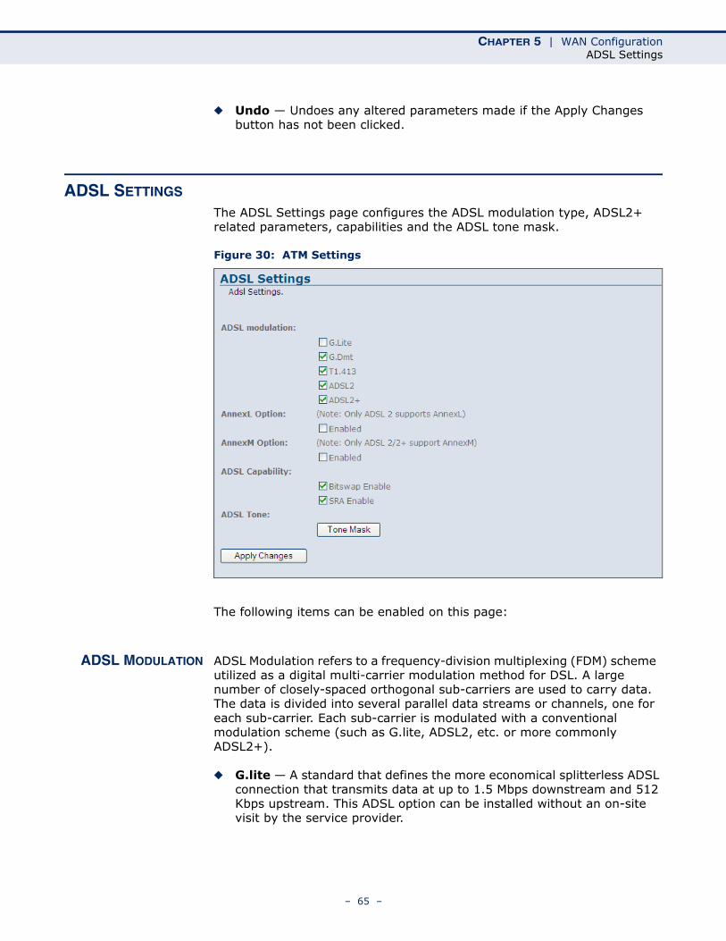
ADSL SETTINGS
The ADSL Settings page configures the ADSL modulation type, ADSL2+ related parameters, capabilities and the ADSL tone mask.
Figure 30: ATM Settings
The following items can be enabled on this page:
ADSL MODULATION ADSL Modulation refers to a frequency-division multiplexing (FDM) scheme utilized as a digital multi-carrier modulation method for DSL. A large number of closely-spaced orthogonal sub-carriers are used to carry data. The data is divided into several parallel data streams or channels, one for each sub-carrier. Each sub-carrier is modulated with a conventional modulation scheme (such as G.lite, ADSL2, etc. or more commonly ADSL2+).
◆ G.lite — A standard that defines the more economical splitterless ADSL connection that transmits data at up to 1.5 Mbps downstream and 512 Kbps upstream. This ADSL option can be installed without an on-site visit by the service provider.
– 65 –
CHAPTER 5 | WAN ConfigurationADSL Settings
◆ G.dmt — A standard that defines full-rate ADSL, and utilizes Discrete Multi-Tone (DMT) signaling to transmit data at up to 8 Mbps downstream and 640 Kbps upstream.
◆ T1.413 — ANSI standard that defines the requirements for ADSL for the interface between the telecommunications network and the customer installation in terms of their interaction and electrical characteristics. (The Gateway complies with Issue 2 of this standard.)
◆ ADSL2 — This standard extends the capability of basic ADSL data rates to 12 Mbit/s downstream and 3 Mbit/s upstream (with a mandatory capability of ADSL2 transceivers of 8 Mbit/s downstream and 800 Kbit/s upstream.
◆ ADSL2+ — This standard extends the capability of basic ADSL data rates to 24 Mbit/s downstream and 1.4 Mbit/s upstream depending on the distance from the DSLAM to the customer's home.
ANNEXL OPTION Annex L is an optional specification in the ITU-T ADSL2 recomendation G.992.3 titled “Specific requirements for a Reach Extended ADSL2 (READSL2) system operating in the frequency band above POTS.” It is often referred to as Reach Extended ADSL2 or READSL2.
◆ Enabled — Once enabled AnnexL increases the range of DSL service, enabling the link to work at a distance of 7 kilometers, or 23,000 feet.
ANNEXM OPTION Annex M is an optional specification in ITU-T recomendations G.992.3 (ADSL2) and G.992.5 (ADSL2+), also referred to as ADSL2 M and ADSL2+ M. This specification extends the capability of commonly deployed Annex A by more than doubling the number of upstream bits.
◆ Enabled — Once enabled AnnexM increases upload speeds by the shifting the upstream/downstream frequency split from 138 kHz up to 276 kHz, allowing the maximum upstream bandwidth to be increased from 1.4 Mbit/s to 3.3 Mbit/s.
ADSL CAPABILITY ADSL Capability refers to means of manipulating the bit loading of a connection to increase quality of signal or transmission rate.
◆ Bitswap — Enables bit swapping. Bit swapping is a way of swapping the bit-loading of a noisy tone with another tone in the symbol which is not as noisy. The bit loading from a specific tone can be increased or decreased. In addition, the TX power can be increased or decreased for a specific tone. However, there is no change in the overall payload rate after the bit swap operation.
◆ SRA — Enables seamless rate adaptation to set the optimal transmission rate based on existing line conditions.
– 66 –
CHAPTER 5 | WAN ConfigurationADSL Settings
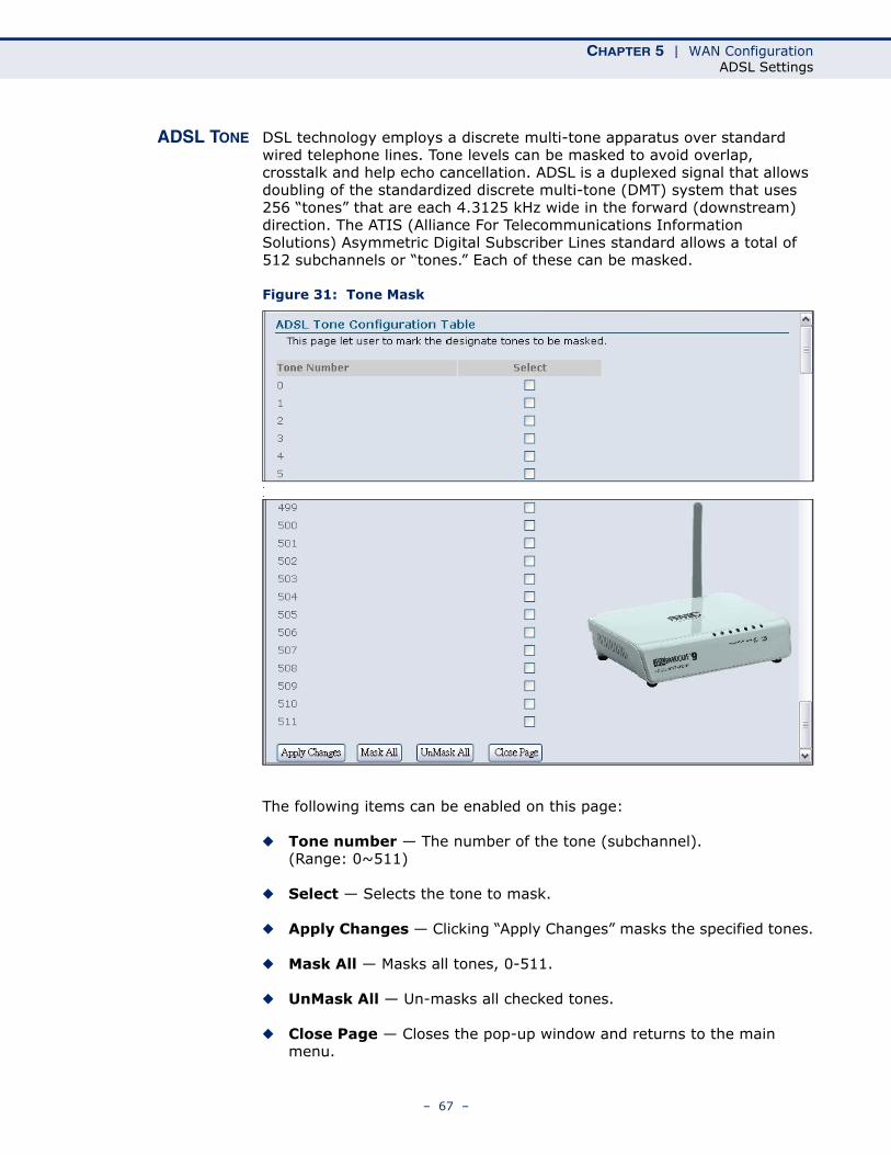
ADSL TONE DSL technology employs a discrete multi-tone apparatus over standard wired telephone lines. Tone levels can be masked to avoid overlap, crosstalk and help echo cancellation. ADSL is a duplexed signal that allows doubling of the standardized discrete multi-tone (DMT) system that uses 256 “tones” that are each 4.3125 kHz wide in the forward (downstream) direction. The ATIS (Alliance For Telecommunications Information Solutions) Asymmetric Digital Subscriber Lines standard allows a total of 512 subchannels or “tones.” Each of these can be masked.
Figure 31: Tone Mask
.
.
The following items can be enabled on this page:
◆ Tone number — The number of the tone (subchannel). (Range: 0~511)
◆ Select — Selects the tone to mask.
◆ Apply Changes — Clicking “Apply Changes” masks the specified tones.
◆ Mask All — Masks all tones, 0-511.
◆ UnMask All — Un-masks all checked tones.
◆ Close Page — Closes the pop-up window and returns to the main menu.
– 67 –

CHAPTER 5 | WAN ConfigurationADSL Settings
– 68 –
6 LAN CONFIGURATION
This chapter describes LAN configuration on the ADSL Router.
You can use the web browser interface to access IP addressing only if the ADSL Router already has an IP address that is reachable through your network.
◆ “LAN Interface” on page 69
◆ “DHCP Settings” on page 70
LAN INTERFACE
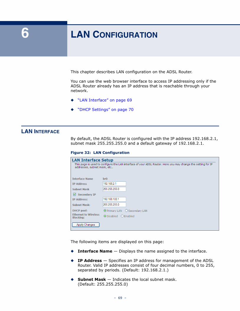
By default, the ADSL Router is configured with the IP address 192.168.2.1, subnet mask 255.255.255.0 and a default gateway of 192.168.2.1.
Figure 32: LAN Configuration
The following items are displayed on this page:
◆ Interface Name — Displays the name assigned to the interface.
◆ IP Address — Specifies an IP address for management of the ADSL Router. Valid IP addresses consist of four decimal numbers, 0 to 255, separated by periods. (Default: 192.168.2.1.)
◆ Subnet Mask — Indicates the local subnet mask. (Default: 255.255.255.0)
– 69 –
CHAPTER 6 | LAN ConfigurationDHCP Settings
◆ Secondary IP Address — Specifies a secondary IP address for management of the unit.
◆ DHCP Pool — Selects either the primary or secondary IP address to enable DHCP under.
◆ Ethernet to Wireless Blocking — Enables/disables access to the Ethernet port by wireless clients.
DHCP SETTINGS
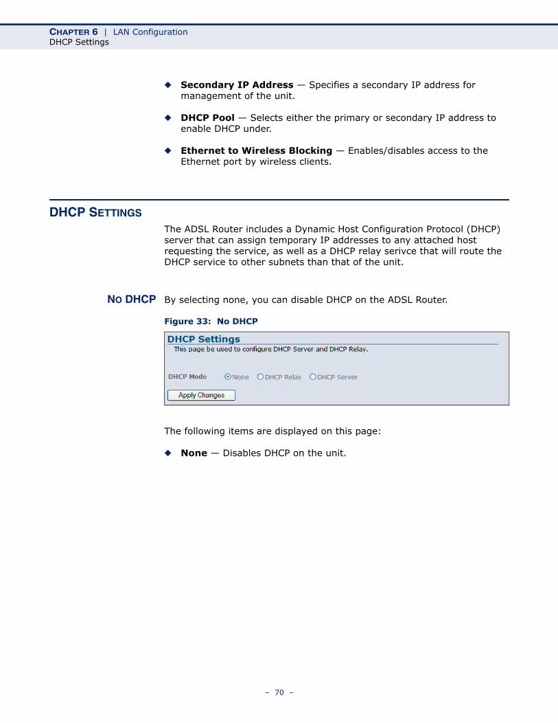
The ADSL Router includes a Dynamic Host Configuration Protocol (DHCP) server that can assign temporary IP addresses to any attached host requesting the service, as well as a DHCP relay serivce that will route the DHCP service to other subnets than that of the unit.
NO DHCP By selecting none, you can disable DHCP on the ADSL Router.
Figure 33: No DHCP
The following items are displayed on this page:
◆ None — Disables DHCP on the unit.
– 70 –
CHAPTER 6 | LAN ConfigurationDHCP Settings
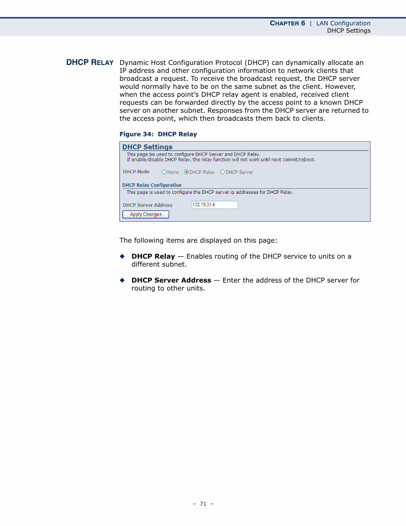
DHCP RELAY Dynamic Host Configuration Protocol (DHCP) can dynamically allocate an IP address and other configuration information to network clients that broadcast a request. To receive the broadcast request, the DHCP server would normally have to be on the same subnet as the client. However, when the access point’s DHCP relay agent is enabled, received client requests can be forwarded directly by the access point to a known DHCP server on another subnet. Responses from the DHCP server are returned to the access point, which then broadcasts them back to clients.
Figure 34: DHCP Relay
The following items are displayed on this page:
◆ DHCP Relay — Enables routing of the DHCP service to units on a different subnet.
◆ DHCP Server Address — Enter the address of the DHCP server for routing to other units.
– 71 –
CHAPTER 6 | LAN ConfigurationDHCP Settings
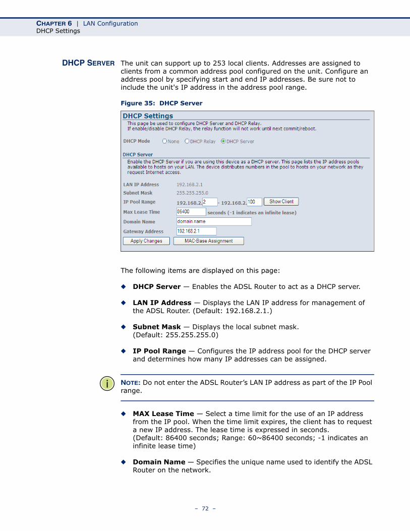
DHCP SERVER The unit can support up to 253 local clients. Addresses are assigned to clients from a common address pool configured on the unit. Configure an address pool by specifying start and end IP addresses. Be sure not to include the unit's IP address in the address pool range.
Figure 35: DHCP Server
The following items are displayed on this page:
◆ DHCP Server — Enables the ADSL Router to act as a DHCP server.
◆ LAN IP Address — Displays the LAN IP address for management of the ADSL Router. (Default: 192.168.2.1.)
◆ Subnet Mask — Displays the local subnet mask. (Default: 255.255.255.0)
◆ IP Pool Range — Configures the IP address pool for the DHCP server and determines how many IP addresses can be assigned.
NOTE: Do not enter the ADSL Router’s LAN IP address as part of the IP Pool range.
◆ MAX Lease Time — Select a time limit for the use of an IP address from the IP pool. When the time limit expires, the client has to request a new IP address. The lease time is expressed in seconds.(Default: 86400 seconds; Range: 60~86400 seconds; -1 indicates an infinite lease time)
◆ Domain Name — Specifies the unique name used to identify the ADSL Router on the network.
– 72 –
CHAPTER 6 | LAN ConfigurationDHCP Settings
◆ Gateway Address — Specifies the gateway address through which traffic is routed from. Usually the LAN IP address of the ADSL Router
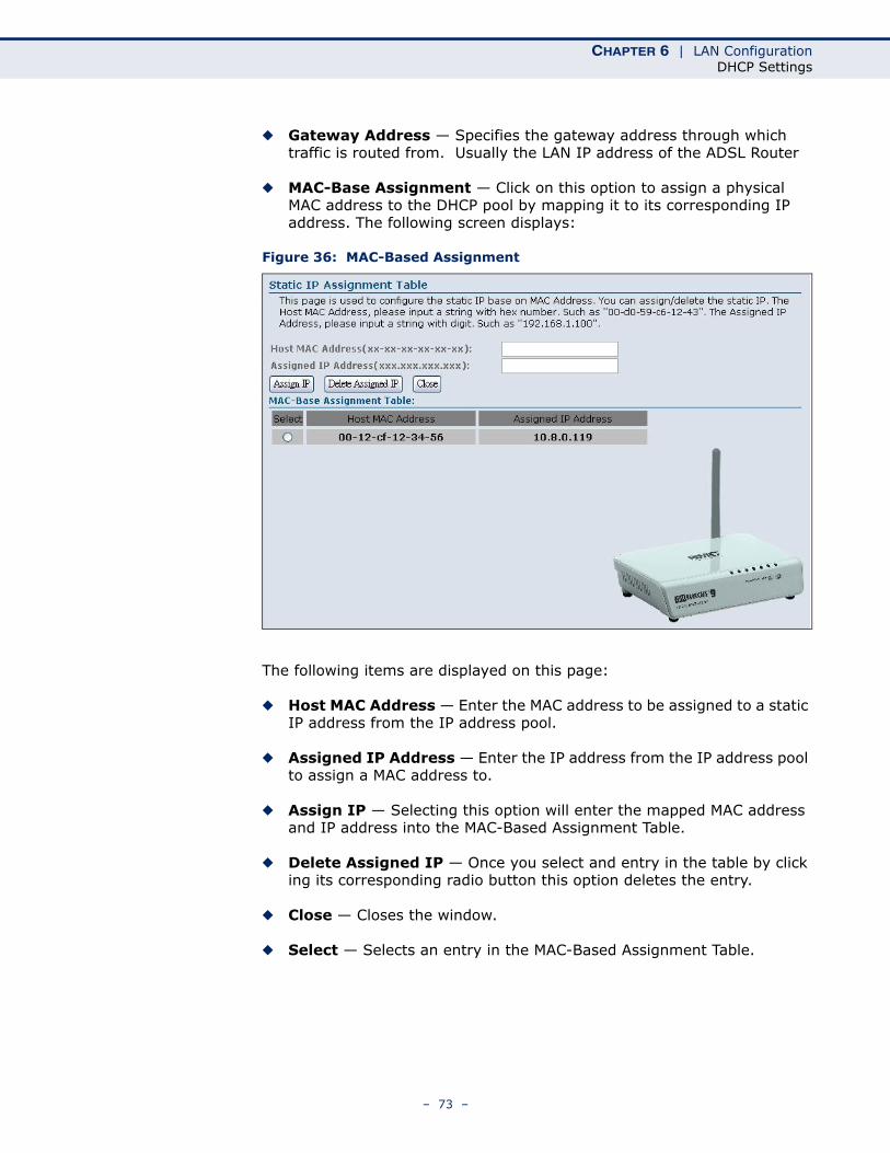
◆ MAC-Base Assignment — Click on this option to assign a physical MAC address to the DHCP pool by mapping it to its corresponding IP address. The following screen displays:
Figure 36: MAC-Based Assignment
The following items are displayed on this page:
◆ Host MAC Address — Enter the MAC address to be assigned to a static IP address from the IP address pool.
◆ Assigned IP Address — Enter the IP address from the IP address pool to assign a MAC address to.
◆ Assign IP — Selecting this option will enter the mapped MAC address and IP address into the MAC-Based Assignment Table.
◆ Delete Assigned IP — Once you select and entry in the table by click ing its corresponding radio button this option deletes the entry.
◆ Close — Closes the window.
◆ Select — Selects an entry in the MAC-Based Assignment Table.
– 73 –

CHAPTER 6 | LAN ConfigurationDHCP Settings
– 74 –
7 WLAN CONFIGURATION
This chapter describes wireless configuration on the ADSL Router. The unit contains an onboard IEEE 802.11b/g access point (AP), which provides wireless data communications between the router and wireless devices.
WLAN Configuration contains the following sections:
◆ “WLAN Basic Settings” on page 76
◆ “Second BSSID” on page 77
◆ “Wireless Security Setup” on page 78
◆ “WPA Security” on page 81
◆ “Access Control” on page 82
◆ “WDS” on page 83
◆ “Advanced Settings” on page 85
– 75 –
CHAPTER 7 | WLAN ConfigurationWLAN Basic Settings
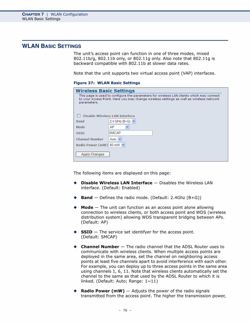
WLAN BASIC SETTINGS
The unit’s access point can function in one of three modes, mixed 802.11b/g, 802.11b only, or 802.11g only. Also note that 802.11g is backward compatible with 802.11b at slower data rates.
Note that the unit supports two virtual access point (VAP) interfaces.
Figure 37: WLAN Basic Settings
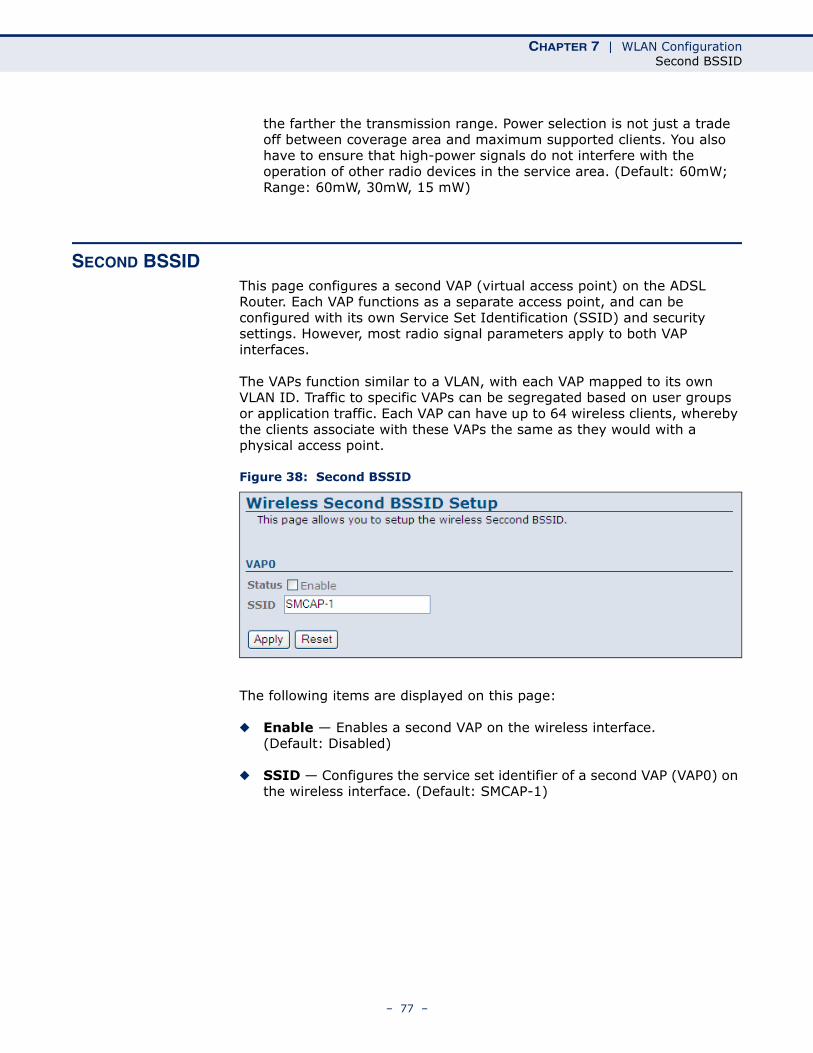
The following items are displayed on this page:
◆ Disable Wireless LAN Interface — Disables the Wireless LAN interface. (Default: Enabled)
◆ Band — Defines the radio mode. (Default: 2.4Ghz (B+G))
◆ Mode — The unit can function as an access point alone allowing connection to wireless clients, or both access point and WDS (wireless distribution system) allowing WDS transparent bridging between APs. (Default: AP)
◆ SSID — The service set identifyer for the access point. (Default: SMCAP)
◆ Channel Number — The radio channel that the ADSL Router uses to communicate with wireless clients. When multiple access points are deployed in the same area, set the channel on neighboring access points at least five channels apart to avoid interference with each other. For example, you can deploy up to three access points in the same area using channels 1, 6, 11. Note that wireless clients automatically set the channel to the same as that used by the ADSL Router to which it is linked. (Default: Auto; Range: 1~11)
◆ Radio Power (mW) — Adjusts the power of the radio signals transmitted from the access point. The higher the transmission power,
– 76 –
CHAPTER 7 | WLAN ConfigurationSecond BSSID
the farther the transmission range. Power selection is not just a trade off between coverage area and maximum supported clients. You also have to ensure that high-power signals do not interfere with the operation of other radio devices in the service area. (Default: 60mW; Range: 60mW, 30mW, 15 mW)
SECOND BSSIDThis page configures a second VAP (virtual access point) on the ADSL Router. Each VAP functions as a separate access point, and can be configured with its own Service Set Identification (SSID) and security settings. However, most radio signal parameters apply to both VAP interfaces.
The VAPs function similar to a VLAN, with each VAP mapped to its own VLAN ID. Traffic to specific VAPs can be segregated based on user groups or application traffic. Each VAP can have up to 64 wireless clients, whereby the clients associate with these VAPs the same as they would with a physical access point.
Figure 38: Second BSSID
The following items are displayed on this page:
◆ Enable — Enables a second VAP on the wireless interface. (Default: Disabled)
◆ SSID — Configures the service set identifier of a second VAP (VAP0) on the wireless interface. (Default: SMCAP-1)
– 77 –
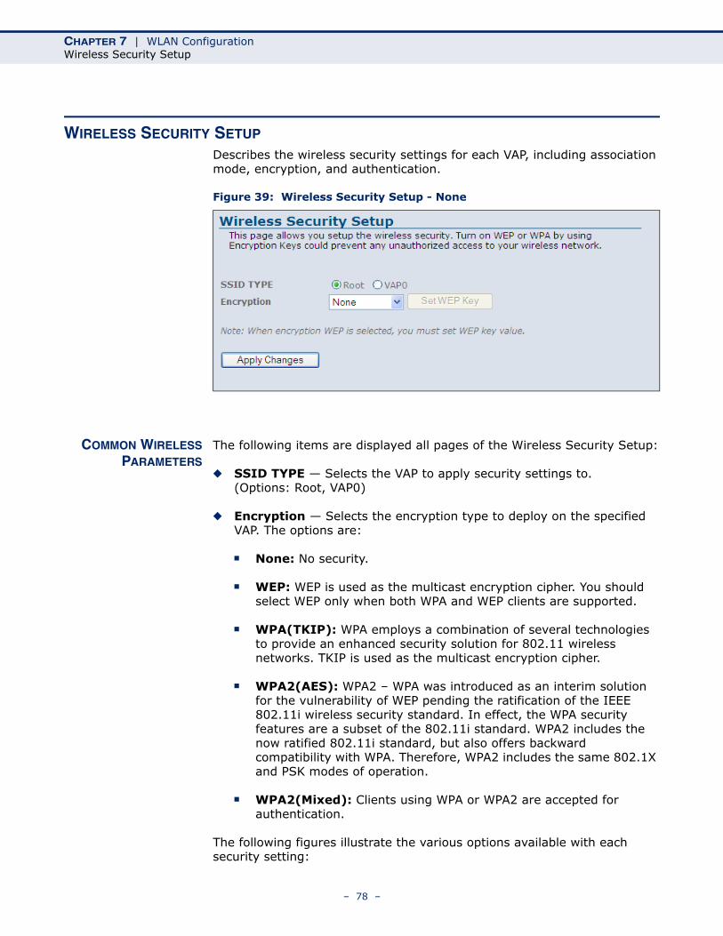
CHAPTER 7 | WLAN ConfigurationWireless Security Setup
WIRELESS SECURITY SETUP
Describes the wireless security settings for each VAP, including association mode, encryption, and authentication.
Figure 39: Wireless Security Setup - None
COMMON WIRELESSPARAMETERS
The following items are displayed all pages of the Wireless Security Setup:
◆ SSID TYPE — Selects the VAP to apply security settings to. (Options: Root, VAP0)
◆ Encryption — Selects the encryption type to deploy on the specified VAP. The options are:
■ None: No security.
■ WEP: WEP is used as the multicast encryption cipher. You should select WEP only when both WPA and WEP clients are supported.
■ WPA(TKIP): WPA employs a combination of several technologies to provide an enhanced security solution for 802.11 wireless networks. TKIP is used as the multicast encryption cipher.
■ WPA2(AES): WPA2 – WPA was introduced as an interim solution for the vulnerability of WEP pending the ratification of the IEEE 802.11i wireless security standard. In effect, the WPA security features are a subset of the 802.11i standard. WPA2 includes the now ratified 802.11i standard, but also offers backward compatibility with WPA. Therefore, WPA2 includes the same 802.1X and PSK modes of operation.
■ WPA2(Mixed): Clients using WPA or WPA2 are accepted for authentication.
The following figures illustrate the various options available with each security setting:
– 78 –
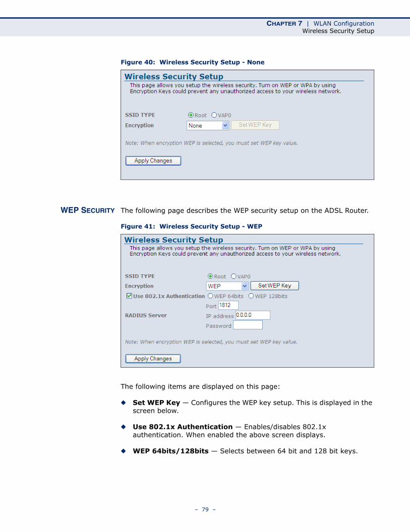
CHAPTER 7 | WLAN ConfigurationWireless Security Setup
Figure 40: Wireless Security Setup - None
WEP SECURITY The following page describes the WEP security setup on the ADSL Router.
Figure 41: Wireless Security Setup - WEP
The following items are displayed on this page:
◆ Set WEP Key — Configures the WEP key setup. This is displayed in the screen below.
◆ Use 802.1x Authentication — Enables/disables 802.1x authentication. When enabled the above screen displays.
◆ WEP 64bits/128bits — Selects between 64 bit and 128 bit keys.
– 79 –
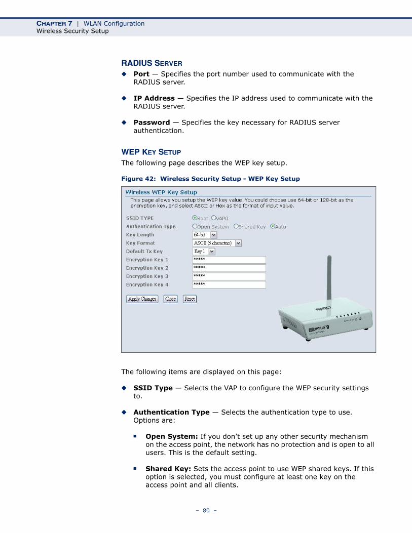
CHAPTER 7 | WLAN ConfigurationWireless Security Setup
RADIUS SERVER
◆ Port — Specifies the port number used to communicate with the RADIUS server.
◆ IP Address — Specifies the IP address used to communicate with the RADIUS server.
◆ Password — Specifies the key necessary for RADIUS server authentication.
WEP KEY SETUP
The following page describes the WEP key setup.
Figure 42: Wireless Security Setup - WEP Key Setup
The following items are displayed on this page:
◆ SSID Type — Selects the VAP to configure the WEP security settings to.
◆ Authentication Type — Selects the authentication type to use. Options are:
■ Open System: If you don’t set up any other security mechanism on the access point, the network has no protection and is open to all users. This is the default setting.
■ Shared Key: Sets the access point to use WEP shared keys. If this option is selected, you must configure at least one key on the access point and all clients.
– 80 –
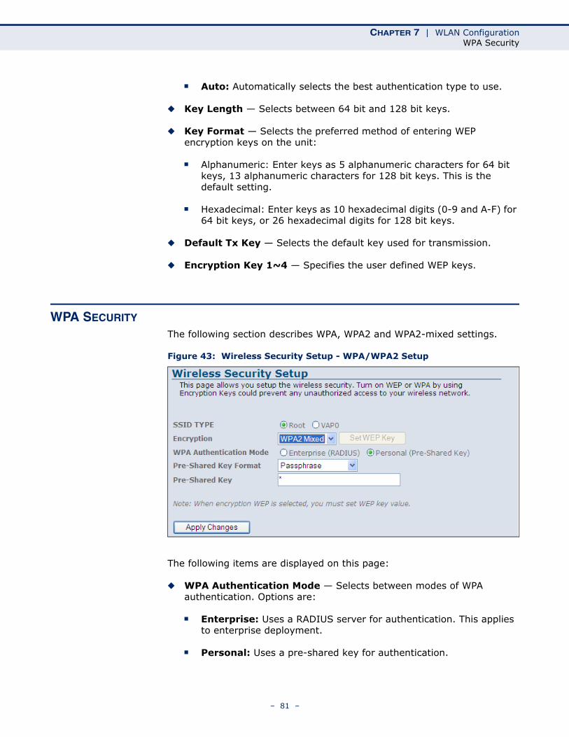
CHAPTER 7 | WLAN ConfigurationWPA Security
■ Auto: Automatically selects the best authentication type to use.
◆ Key Length — Selects between 64 bit and 128 bit keys.
◆ Key Format — Selects the preferred method of entering WEP encryption keys on the unit:
■ Alphanumeric: Enter keys as 5 alphanumeric characters for 64 bit keys, 13 alphanumeric characters for 128 bit keys. This is the default setting.
■ Hexadecimal: Enter keys as 10 hexadecimal digits (0-9 and A-F) for 64 bit keys, or 26 hexadecimal digits for 128 bit keys.
◆ Default Tx Key — Selects the default key used for transmission.
◆ Encryption Key 1~4 — Specifies the user defined WEP keys.
WPA SECURITY
The following section describes WPA, WPA2 and WPA2-mixed settings.
Figure 43: Wireless Security Setup - WPA/WPA2 Setup
The following items are displayed on this page:
◆ WPA Authentication Mode — Selects between modes of WPA authentication. Options are:
■ Enterprise: Uses a RADIUS server for authentication. This applies to enterprise deployment.
■ Personal: Uses a pre-shared key for authentication.
– 81 –
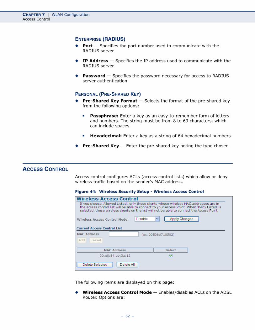
CHAPTER 7 | WLAN ConfigurationAccess Control
ENTERPRISE (RADIUS)◆ Port — Specifies the port number used to communicate with the
RADIUS server.
◆ IP Address — Specifies the IP address used to communicate with the RADIUS server.
◆ Password — Specifies the password necessary for access to RADIUS server authentication.
PERSONAL (PRE-SHARED KEY)◆ Pre-Shared Key Format — Selects the format of the pre-shared key
from the following options:
■ Passphrase: Enter a key as an easy-to-remember form of letters and numbers. The string must be from 8 to 63 characters, which can include spaces.
■ Hexadecimal: Enter a key as a string of 64 hexadecimal numbers.
◆ Pre-Shared Key — Enter the pre-shared key noting the type chosen.
ACCESS CONTROL
Access control configures ACLs (access control lists) which allow or deny wireless traffic based on the sender’s MAC address.
Figure 44: Wireless Security Setup - Wireless Access Control
The following items are displayed on this page:
◆ Wireless Access Control Mode — Enables/disables ACLs on the ADSL Router. Options are:
– 82 –
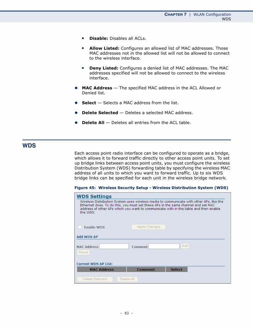
CHAPTER 7 | WLAN ConfigurationWDS
■ Disable: Disables all ACLs.
■ Allow Listed: Configures an allowed list of MAC addresses. Those MAC addresses not in the allowed list will not be allowed to connect to the wireless interface.
■ Deny Listed: Configures a denied list of MAC addresses. The MAC addresses specified will not be allowed to connect to the wireless interface.
◆ MAC Address — The specified MAC address in the ACL Allowed or Denied list.
◆ Select — Selects a MAC address from the list.
◆ Delete Selected — Deletes a selected MAC address.
◆ Delete All — Deletes all entries from the ACL table.
WDSEach access point radio interface can be configured to operate as a bridge, which allows it to forward traffic directly to other access point units. To set up bridge links between access point units, you must configure the wireless Distribution System (WDS) forwarding table by specifying the wireless MAC address of all units to which you want to forward traffic. Up to six WDS bridge links can be specified for each unit in the wireless bridge network.
Figure 45: Wireless Security Setup - Wireless Distribution System (WDS)
– 83 –
CHAPTER 7 | WLAN ConfigurationWDS
The following items are displayed on this page:
NOTE: The Mode of the radio, under Basic Settings, must be set to AP+WDS before enabling WDS.
◆ Enable WDS — Enables WDS bridging on the radio interface.
ADD WDS APAllows the user to enter up to six MAC addresses for WDS bridging.
◆ Apply Changes — Adds the specified MAC address to the Current WDS AP List.
◆ MAC Address — Specifies a MAC address in the format xxxxxxxxxxxx.
◆ Comment — Specifies a comment to help identify the MAC address.
◆ Add — Adds the user entered MAC address and Comment information to the table.
◆ Reset — Clears the fields.
CURRENT WDS AP LIST
Displays the current entries in the WDS AP List.
◆ MAC Address — Displays a MAC address entry.
◆ Comment — Displays a useful comment that may help to identify the MAC address.
◆ Select — Selects a MAC address entry.
◆ Delete Selected — Deletes the selected MAC address entry.
◆ Delete All — Deletes all entries from the table.
– 84 –
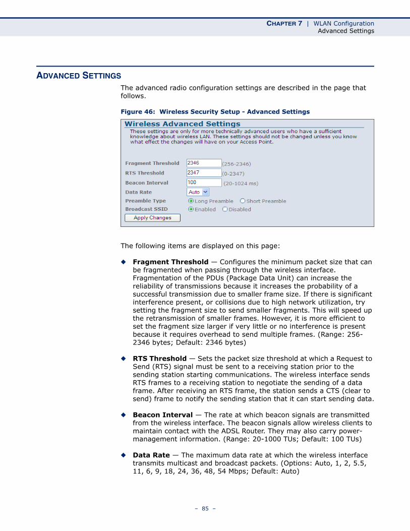
CHAPTER 7 | WLAN ConfigurationAdvanced Settings
ADVANCED SETTINGS
The advanced radio configuration settings are described in the page that follows.
Figure 46: Wireless Security Setup - Advanced Settings
The following items are displayed on this page:
◆ Fragment Threshold — Configures the minimum packet size that can be fragmented when passing through the wireless interface. Fragmentation of the PDUs (Package Data Unit) can increase the reliability of transmissions because it increases the probability of a successful transmission due to smaller frame size. If there is significant interference present, or collisions due to high network utilization, try setting the fragment size to send smaller fragments. This will speed up the retransmission of smaller frames. However, it is more efficient to set the fragment size larger if very little or no interference is present because it requires overhead to send multiple frames. (Range: 256-2346 bytes; Default: 2346 bytes)
◆ RTS Threshold — Sets the packet size threshold at which a Request to Send (RTS) signal must be sent to a receiving station prior to the sending station starting communications. The wireless interface sends RTS frames to a receiving station to negotiate the sending of a data frame. After receiving an RTS frame, the station sends a CTS (clear to send) frame to notify the sending station that it can start sending data.
◆ Beacon Interval — The rate at which beacon signals are transmitted from the wireless interface. The beacon signals allow wireless clients to maintain contact with the ADSL Router. They may also carry power-management information. (Range: 20-1000 TUs; Default: 100 TUs)
◆ Data Rate — The maximum data rate at which the wireless interface transmits multicast and broadcast packets. (Options: Auto, 1, 2, 5.5, 11, 6, 9, 18, 24, 36, 48, 54 Mbps; Default: Auto)
– 85 –
CHAPTER 7 | WLAN ConfigurationAdvanced Settings
◆ Preamble Type — Sets the length of the signal preamble that is used at the start of a data transmission. (Default: Long)
■ Long Preamble: Sets the preamble to long (192 microseconds). Using a long preamble ensures the wireless interface can support all 802.11b and 802.11g clients.
■ Short Preamble: Sets the preamble according to the capability of clients that are currently asscociated. Uses a short preamble (96 microseconds) if all associated clients can support it, otherwise a long preamble is used. The wireless interface can increase data throughput when using a short preamble, but will only use a short preamble if it determines that all associated clients support it.
◆ Broadcast SSID — Enables/disables the wireless interface to broadcast an SSID (service set identifier) to uniquely identify it on the network.
◆ Apply Changes — Applies the specified changes.
– 86 –
8 FIREWALL CONFIGURATION
The ADSL Router provides extensive firewall protection by restricting connection parameters to limit the risk of intrusion, and defending against a wide array of common hacker attacks.
Firewall Configuration contains the following sections:
◆ “IP/Port Filtering” on page 88
◆ “MAC Filtering” on page 90
◆ “Port Forwarding” on page 92
◆ “URL Blocking” on page 94
◆ “Domain Blocking” on page 95
◆ “DMZ” on page 96
◆ “DoS” on page 98
– 87 –
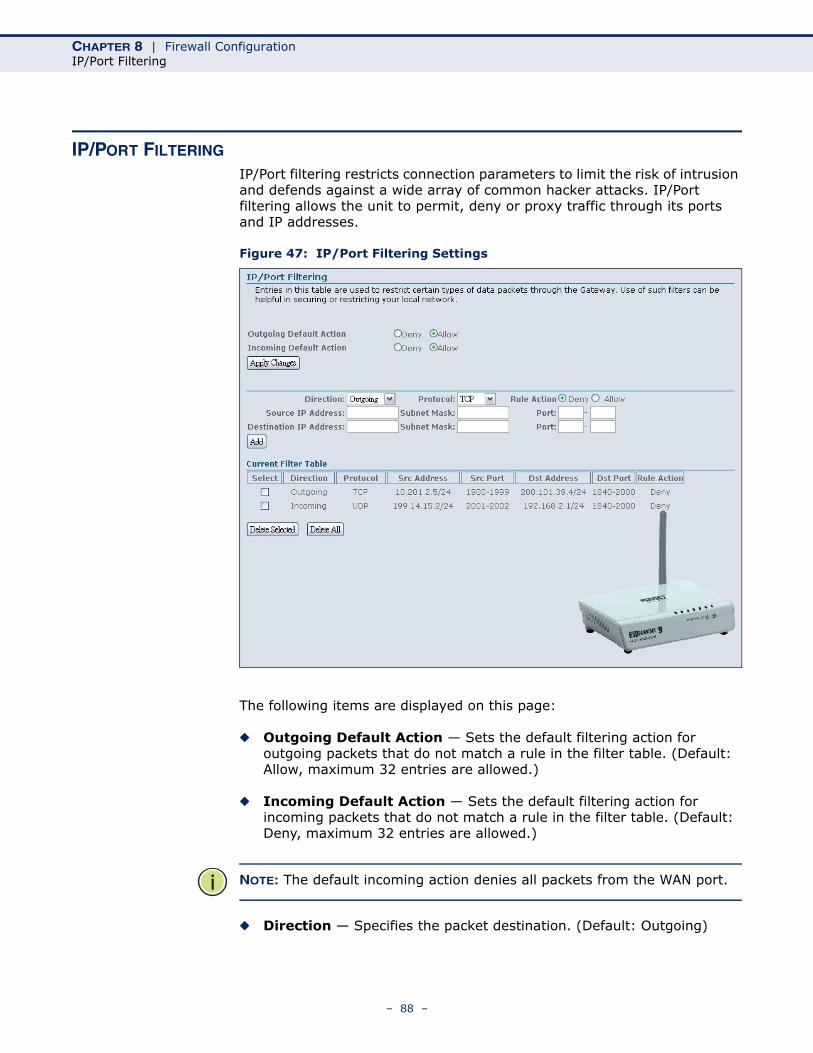
CHAPTER 8 | Firewall ConfigurationIP/Port Filtering
IP/PORT FILTERING
IP/Port filtering restricts connection parameters to limit the risk of intrusion and defends against a wide array of common hacker attacks. IP/Port filtering allows the unit to permit, deny or proxy traffic through its ports and IP addresses.
Figure 47: IP/Port Filtering Settings
The following items are displayed on this page:
◆ Outgoing Default Action — Sets the default filtering action for outgoing packets that do not match a rule in the filter table. (Default: Allow, maximum 32 entries are allowed.)
◆ Incoming Default Action — Sets the default filtering action for incoming packets that do not match a rule in the filter table. (Default: Deny, maximum 32 entries are allowed.)
NOTE: The default incoming action denies all packets from the WAN port.
◆ Direction — Specifies the packet destination. (Default: Outgoing)
– 88 –
CHAPTER 8 | Firewall ConfigurationIP/Port Filtering
◆ Protocol — Specifies the destination port type, TCP, UDP or ICMP. (Default: TCP).
◆ Rule Action — Specifies if traffic should be permitted or denied. (Options: Deny, Allow; Default: Deny)
◆ Source IP Address — Specifies the source IP address to block or allow traffic from.
◆ Destination IP Address — Specifies the destination IP address to block or allow traffic from.
◆ Subnet Mask — Specifies a subnet mask.
◆ Port — Specifies a range of ports to block traffic from the specified LAN IP address from reaching.
◆ Add — Adds a newly configured packet filter that denies forwarding in to the local area network to the list.
CURRENT FILTER TABLE
The Current Filter Table displays the configured IP addresses and ports that are permitted or denied access to and from the ADSL Router.
◆ Select — Selects a table entry.
◆ Direction — Displays the direction in which the rule has been applied.
◆ Protocol — Displays the destination port type.
◆ Src Address — Displays the source IP address.
◆ Src Port — Displays the source port range.
◆ Dst Address — Displays the destination IP address.
◆ Dst Port — Displays the destination port range.
◆ Rule Action — Displays if the specified traffic is allowed or denied.
◆ Delete Selected — Deletes a selected entry from the table.
◆ Delete All — Deletes all entries in the table.
– 89 –
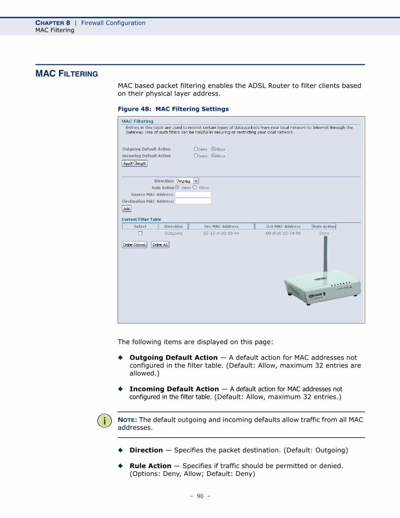
CHAPTER 8 | Firewall ConfigurationMAC Filtering
MAC FILTERING
MAC based packet filtering enables the ADSL Router to filter clients based on their physical layer address.
Figure 48: MAC Filtering Settings
The following items are displayed on this page:
◆ Outgoing Default Action — A default action for MAC addresses not configured in the filter table. (Default: Allow, maximum 32 entries are allowed.)
◆ Incoming Default Action — A default action for MAC addresses not configured in the filter table. (Default: Allow, maximum 32 entries.)
NOTE: The default outgoing and incoming defaults allow traffic from all MAC addresses.
◆ Direction — Specifies the packet destination. (Default: Outgoing)
◆ Rule Action — Specifies if traffic should be permitted or denied. (Options: Deny, Allow; Default: Deny)
– 90 –

CHAPTER 8 | Firewall ConfigurationMAC Filtering
◆ Source MAC Address — Specifies a source MAC address.
◆ Destination MAC Address — Specifies a destination MAC address.
◆ Add — Adds a newly configured packet filter that denies forwarding in to the local area network to the list.
CURRENT FILTER TABLE
◆ Select — Selects a table entry.
◆ Direction — Displays the direction in which the rule has been applied.
◆ Src MAC Address — Displays a source MAC address to filter.
◆ Dst MAC Address — Displays a destination MAC address to filter.
◆ Rule Action — Displays if the specified traffic is allowed or denied.
– 91 –
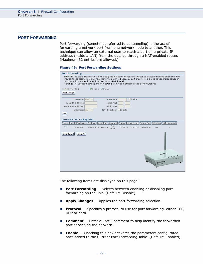
CHAPTER 8 | Firewall ConfigurationPort Forwarding
PORT FORWARDING
Port forwarding (sometimes referred to as tunneling) is the act of forwarding a network port from one network node to another. This technique can allow an external user to reach a port on a private IP address (inside a LAN) from the outside through a NAT-enabled router. (Maximum 32 entries are allowed.)
Figure 49: Port Forwarding Settings
The following items are displayed on this page:
◆ Port Forwarding — Selects between enabling or disabling port forwarding on the unit. (Default: Disable)
◆ Apply Changes — Applies the port forwarding selection.
◆ Protocol — Specifies a protocol to use for port forwarding, either TCP, UDP or both.
◆ Comment — Enter a useful comment to help identify the forwarded port service on the network.
◆ Enable — Checking this box activates the parameters configurated once added to the Current Port Forwarding Table. (Default: Enabled)
– 92 –
CHAPTER 8 | Firewall ConfigurationPort Forwarding
◆ Local IP Address — Specifies the IP address on the local network to allow external access to.
◆ Local Port — Specifies the port range through which traffic is forwarded.
◆ Remote IP Address — Specifies the source IP address on the WAN to allow access from. Leaving this parameter blank allows access from all traffic.
◆ Public Port — Specifies the external port range on the WAN to allow access from.
◆ Interface — Selects the WAN interface on which the port forwarding rule is to be applied.
◆ Add — Adds the configured port forwarding parameters to the Current Port Forwarding Table.
CURRENT PORT FORWARDING TABLE
The Current Port Forwarding Table displays the entries that are allowed to forward packets through the ADSL Router’s firewall.
◆ Select — Selects an entry in the Current Port Forwarding Table.
◆ Local IP Address — Displays an IP address on the local network to allow external access to.
◆ Protocol — Displays the protocol used for forwarding of this port.
◆ Local Port — Displays the local port range.
◆ Comment — Displays a useful comment to identify the nature of the port to be forwarded.
◆ Enable — Displays if the configured port forwarding setup has been enabled.
◆ Remote Host — Displays the source IP address on the WAN to allow access from.
◆ Public Port — Displays the external port range on the WAN to allow access from.
◆ Interface — Displays the WAN interface on which the port forwarding rule is applied.
◆ Delete Selected — Deletes a selected entry from the Current Port Forwarding Table.
◆ Delete All — Deletes all entries in the table.
– 93 –
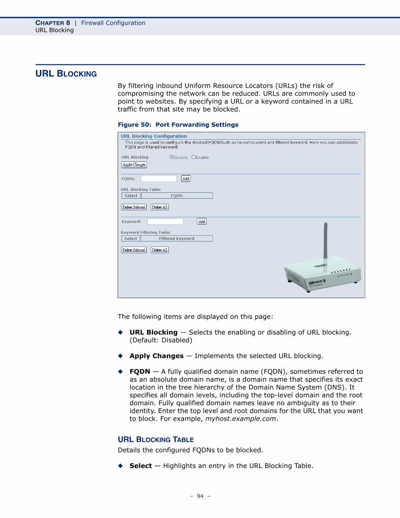
CHAPTER 8 | Firewall ConfigurationURL Blocking
URL BLOCKING
By filtering inbound Uniform Resource Locators (URLs) the risk of compromising the network can be reduced. URLs are commonly used to point to websites. By specifying a URL or a keyword contained in a URL traffic from that site may be blocked.
Figure 50: Port Forwarding Settings
The following items are displayed on this page:
◆ URL Blocking — Selects the enabling or disabling of URL blocking. (Default: Disabled)
◆ Apply Changes — Implements the selected URL blocking.
◆ FQDN — A fully qualified domain name (FQDN), sometimes referred to as an absolute domain name, is a domain name that specifies its exact location in the tree hierarchy of the Domain Name System (DNS). It specifies all domain levels, including the top-level domain and the root domain. Fully qualified domain names leave no ambiguity as to their identity. Enter the top level and root domains for the URL that you want to block. For example, myhost.example.com.
URL BLOCKING TABLE
Details the configured FQDNs to be blocked.
◆ Select — Highlights an entry in the URL Blocking Table.
– 94 –
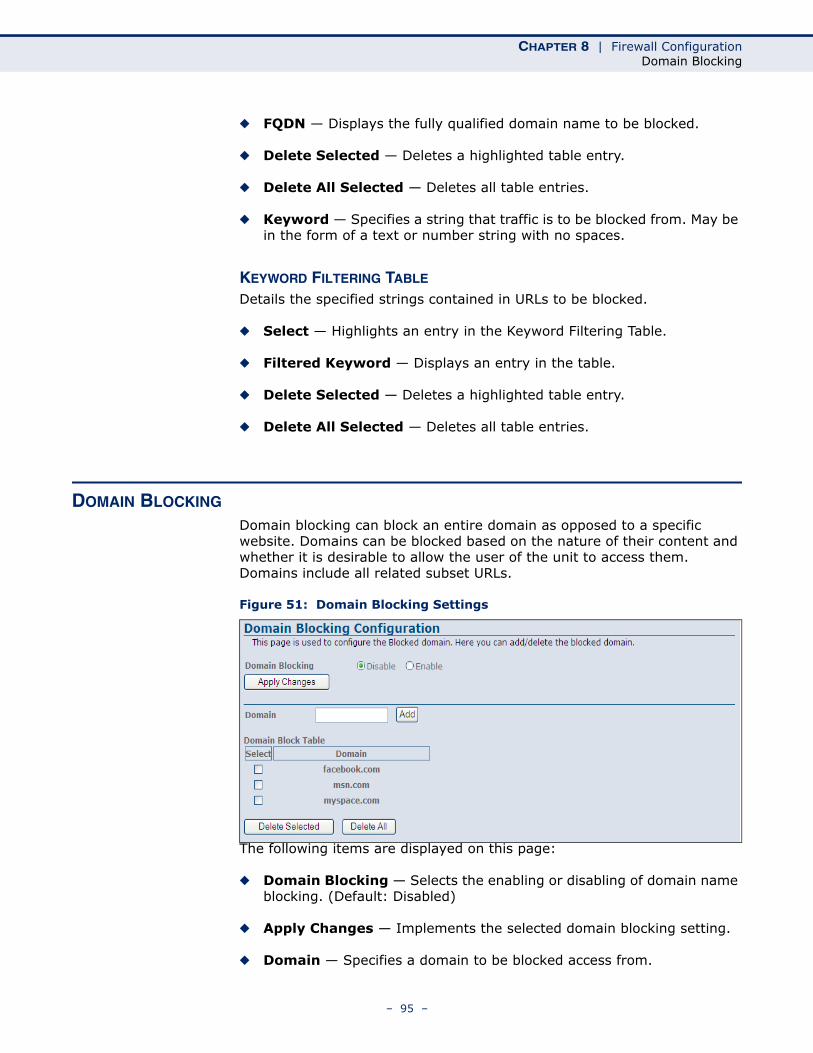
CHAPTER 8 | Firewall ConfigurationDomain Blocking
◆ FQDN — Displays the fully qualified domain name to be blocked.
◆ Delete Selected — Deletes a highlighted table entry.
◆ Delete All Selected — Deletes all table entries.
◆ Keyword — Specifies a string that traffic is to be blocked from. May be in the form of a text or number string with no spaces.
KEYWORD FILTERING TABLE
Details the specified strings contained in URLs to be blocked.
◆ Select — Highlights an entry in the Keyword Filtering Table.
◆ Filtered Keyword — Displays an entry in the table.
◆ Delete Selected — Deletes a highlighted table entry.
◆ Delete All Selected — Deletes all table entries.
DOMAIN BLOCKING
Domain blocking can block an entire domain as opposed to a specific website. Domains can be blocked based on the nature of their content and whether it is desirable to allow the user of the unit to access them. Domains include all related subset URLs.
Figure 51: Domain Blocking Settings
The following items are displayed on this page:
◆ Domain Blocking — Selects the enabling or disabling of domain name blocking. (Default: Disabled)
◆ Apply Changes — Implements the selected domain blocking setting.
◆ Domain — Specifies a domain to be blocked access from.
– 95 –
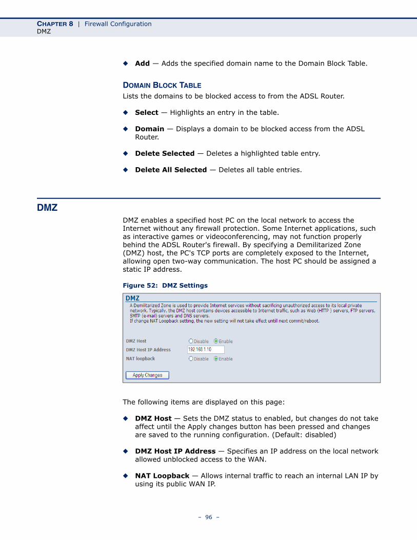
CHAPTER 8 | Firewall ConfigurationDMZ
◆ Add — Adds the specified domain name to the Domain Block Table.
DOMAIN BLOCK TABLE
Lists the domains to be blocked access to from the ADSL Router.
◆ Select — Highlights an entry in the table.
◆ Domain — Displays a domain to be blocked access from the ADSL Router.
◆ Delete Selected — Deletes a highlighted table entry.
◆ Delete All Selected — Deletes all table entries.
DMZDMZ enables a specified host PC on the local network to access the Internet without any firewall protection. Some Internet applications, such as interactive games or videoconferencing, may not function properly behind the ADSL Router's firewall. By specifying a Demilitarized Zone (DMZ) host, the PC's TCP ports are completely exposed to the Internet, allowing open two-way communication. The host PC should be assigned a static IP address.
Figure 52: DMZ Settings
The following items are displayed on this page:
◆ DMZ Host — Sets the DMZ status to enabled, but changes do not take affect until the Apply changes button has been pressed and changes are saved to the running configuration. (Default: disabled)
◆ DMZ Host IP Address — Specifies an IP address on the local network allowed unblocked access to the WAN.
◆ NAT Loopback — Allows internal traffic to reach an internal LAN IP by using its public WAN IP.
– 96 –
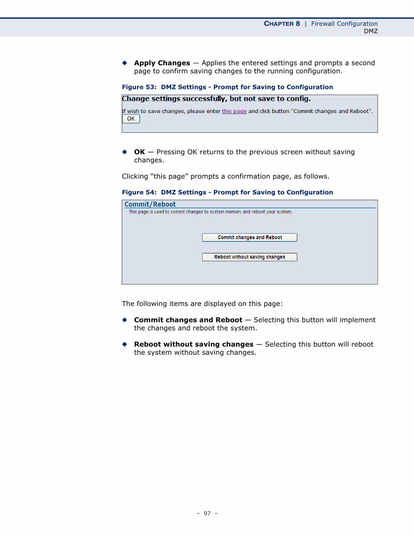
CHAPTER 8 | Firewall ConfigurationDMZ
◆ Apply Changes — Applies the entered settings and prompts a second page to confirm saving changes to the running configuration.
Figure 53: DMZ Settings - Prompt for Saving to Configuration
◆ OK — Pressing OK returns to the previous screen without saving changes.
Clicking “this page” prompts a confirmation page, as follows.
Figure 54: DMZ Settings - Prompt for Saving to Configuration
The following items are displayed on this page:
◆ Commit changes and Reboot — Selecting this button will implement the changes and reboot the system.
◆ Reboot without saving changes — Selecting this button will reboot the system without saving changes.
– 97 –
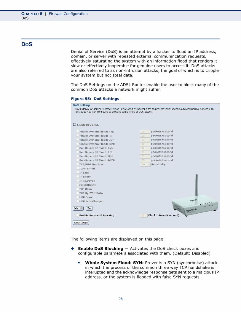
CHAPTER 8 | Firewall ConfigurationDoS
DOSDenial of Service (DoS) is an attempt by a hacker to flood an IP address, domain, or server with repeated external communincation requests, effectively saturating the system with an information flood that renders it slow or effectively inoperable for genuine users to access it. DoS attacks are also referred to as non-intrusion attacks, the goal of which is to cripple your system but not steal data.
The DoS Settings on the ADSL Router enable the user to block many of the common DoS attacks a network might suffer.
Figure 55: DoS Settings
The following items are displayed on this page:
◆ Enable DoS Blocking — Activates the DoS check boxes and configurable parameters associated with them. (Default: Disabled)
■ Whole System Flood: SYN: Prevents a SYN (synchronise) attack in which the process of the common three way TCP handshake is interupted and the acknowledge response gets sent to a maicious IP address, or the system is flooded with false SYN requests.
– 98 –
CHAPTER 8 | Firewall ConfigurationDoS
■ Whole System Flood: FIN: Prevents a FIN (no more data from sender) flood in which part of a TCP packet from an invalid (or spoofed) IP address floods the network with connection resets.
■ Whole System Flood: UDP: Prevents a flood of large numbers of raw UDP (User Datagram Protocol) packets targeted at the unit.
■ Whole System Flood: ICMP: Prevents a flood of ICMP (internet control message protocol) messages from an invalid IP address causing all TCP requests to be halted.
■ Per Source IP Flood: SYN: Prevents a SYN attach on a specified IP address, usually that of the LAN port.
■ Per Source IP Flood: FIN: Prevents a FIN attach on the LAN port IP address.
■ Per Source IP Flood: UDP: Prevents a UDP attack on the LAN port IP address.
■ Per Source IP Flood: ICMP: Prevents an ICMP attack on the LAN port IP address.
■ TCP/UDP Port Scan: Prevents a situation whereby a hacker sends a series of systematic queries to the unit for open ports through which to route traffic.
■ TCMP Smurf: Prevents a situation whereby a hacker forges the IP address of the unit and sends repeated ping requests to it flooding the network.
■ IP Land: Prevents an attack that involves a synchronise request being sent as part of the TCP handshake to an open port specifying the port as both the source and destination effectively locking the port.
■ IP Spoof: Prevents a situation where a hackerby a hacker creates an alias (spoof) of the units IP address to which all traffic is redirected.
■ IP Teardrop: Prevents a Teardrop attack that involves sending mangled IP fragments with overlapping, over-sized, payloads to the unit. The fragmented packets are processed by the unit causing it to crash.
■ PingofDeath: Prevents the receival of an oversized ping packet that the unit cannot handle. Normal ping packets are 56 bytes, or 84 bytes with the IP header attached. The Ping of Death will exceed the maximum IP packet size of 65,535 bytes.
■ TCP Scan: Prevents the probing of the unit by a hacker for open TCP ports to then block.
– 99 –
CHAPTER 8 | Firewall ConfigurationDoS
■ TCP SynWithData: Prevents the hacker sending a volume of requests for connections that cannot be completed.
■ UDP Bomb: Also called a UDP Flood or packet storm. Prevents the hacker congesting the network by generating a flood of UDP packets between it and the unit using the UDP chargen service (a testing utility that generates a character string for every packet it receives).
■ UDP EchoChargen: Prevents the hacker from sending a UDP packet to the echo server with a source port set to the chargen port.
■ packets/second: Enter the number of packets per second that you want to scan for malicious activity.
■ Sensitivity: Specifies the sensivity of the TCP/UDP port scan prevention. (Options: High, Low; Default: Low)
◆ Select All — Selects all DoS prevention measures listed.
◆ Clear — Clears all fields.
◆ Enable Source IP Blocking — When multiple attacks are detected from each of the fields listed above, or the packet threshold has been exceeded - the IP address of the hacker is blocked.
◆ Block Interval (second) — Sets the length of time the IP address should remain blocked.
– 100 –
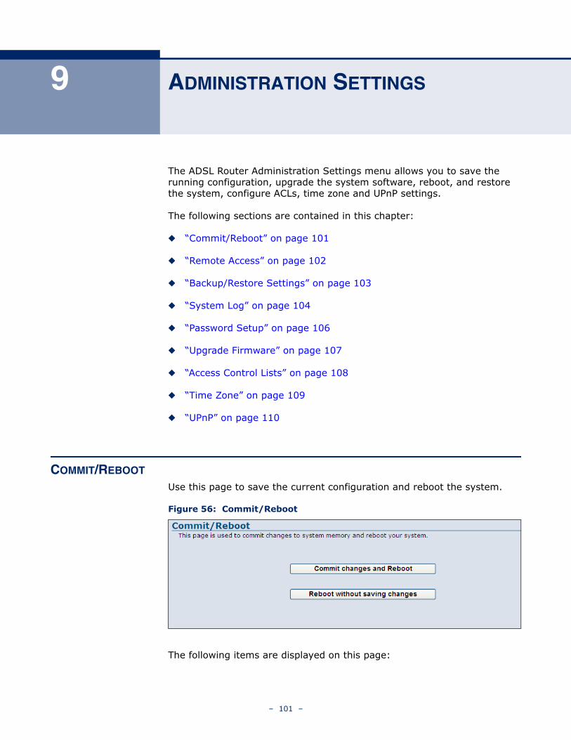
9 ADMINISTRATION SETTINGS
The ADSL Router Administration Settings menu allows you to save the running configuration, upgrade the system software, reboot, and restore the system, configure ACLs, time zone and UPnP settings.
The following sections are contained in this chapter:
◆ “Commit/Reboot” on page 101
◆ “Remote Access” on page 102
◆ “Backup/Restore Settings” on page 103
◆ “System Log” on page 104
◆ “Password Setup” on page 106
◆ “Upgrade Firmware” on page 107
◆ “Access Control Lists” on page 108
◆ “Time Zone” on page 109
◆ “UPnP” on page 110
COMMIT/REBOOT
Use this page to save the current configuration and reboot the system.
Figure 56: Commit/Reboot
The following items are displayed on this page:
– 101 –
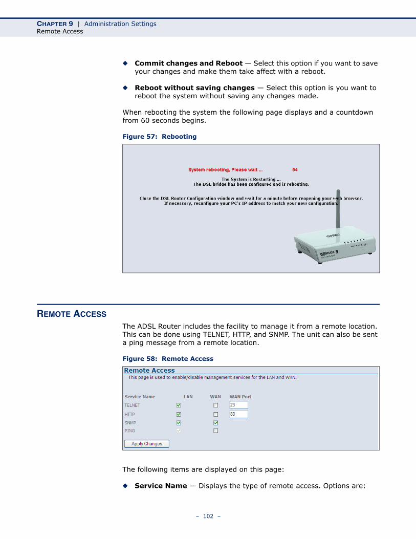
CHAPTER 9 | Administration SettingsRemote Access
◆ Commit changes and Reboot — Select this option if you want to save your changes and make them take affect with a reboot.
◆ Reboot without saving changes — Select this option is you want to reboot the system without saving any changes made.
When rebooting the system the following page displays and a countdown from 60 seconds begins.
Figure 57: Rebooting
REMOTE ACCESS
The ADSL Router includes the facility to manage it from a remote location. This can be done using TELNET, HTTP, and SNMP. The unit can also be sent a ping message from a remote location.
Figure 58: Remote Access
The following items are displayed on this page:
◆ Service Name — Displays the type of remote access. Options are:
– 102 –
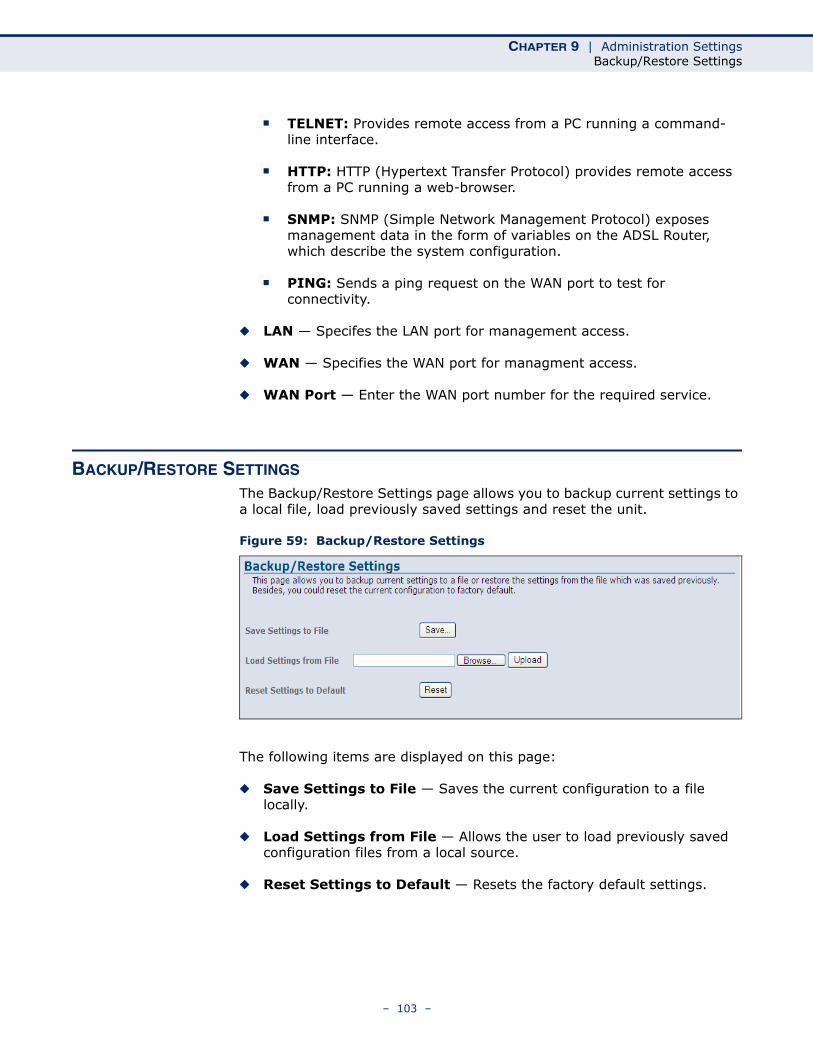
CHAPTER 9 | Administration SettingsBackup/Restore Settings
■ TELNET: Provides remote access from a PC running a command-line interface.
■ HTTP: HTTP (Hypertext Transfer Protocol) provides remote access from a PC running a web-browser.
■ SNMP: SNMP (Simple Network Management Protocol) exposes management data in the form of variables on the ADSL Router, which describe the system configuration.
■ PING: Sends a ping request on the WAN port to test for connectivity.
◆ LAN — Specifes the LAN port for management access.
◆ WAN — Specifies the WAN port for managment access.
◆ WAN Port — Enter the WAN port number for the required service.
BACKUP/RESTORE SETTINGS
The Backup/Restore Settings page allows you to backup current settings to a local file, load previously saved settings and reset the unit.
Figure 59: Backup/Restore Settings
The following items are displayed on this page:
◆ Save Settings to File — Saves the current configuration to a file locally.
◆ Load Settings from File — Allows the user to load previously saved configuration files from a local source.
◆ Reset Settings to Default — Resets the factory default settings.
– 103 –
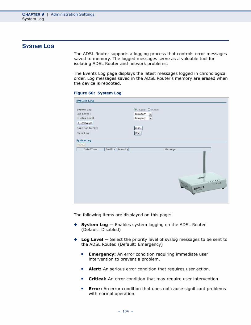
CHAPTER 9 | Administration SettingsSystem Log
SYSTEM LOG
The ADSL Router supports a logging process that controls error messages saved to memory. The logged messages serve as a valuable tool for isolating ADSL Router and network problems.
The Events Log page displays the latest messages logged in chronological order. Log messages saved in the ADSL Router’s memory are erased when the device is rebooted.
Figure 60: System Log
The following items are displayed on this page:
◆ System Log — Enables system logging on the ADSL Router. (Default: Disabled)
◆ Log Level — Select the priority level of syslog messages to be sent to the ADSL Router. (Default: Emergency)
■ Emergency: An error condition requiring immediate user intervention to prevent a problem.
■ Alert: An serious error condition that requires user action.
■ Critical: An error condition that may require user intervention.
■ Error: An error condition that does not cause significant problems with normal operation.
– 104 –
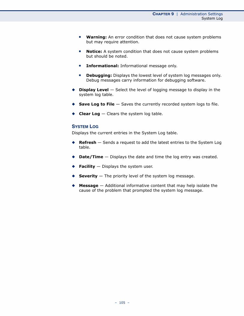
CHAPTER 9 | Administration SettingsSystem Log
■ Warning: An error condition that does not cause system problems but may require attention.
■ Notice: A system condition that does not cause system problems but should be noted.
■ Informational: Informational message only.
■ Debugging: Displays the lowest level of system log messages only. Debug messages carry information for debugging software.
◆ Display Level — Select the level of logging message to display in the system log table.
◆ Save Log to File — Saves the currently recorded system logs to file.
◆ Clear Log — Clears the system log table.
SYSTEM LOG
Displays the current entries in the System Log table.
◆ Refresh — Sends a request to add the latest entries to the System Log table.
◆ Date/Time — Displays the date and time the log entry was created.
◆ Facility — Displays the system user.
◆ Severity — The priority level of the system log message.
◆ Message — Additional informative content that may help isolate the cause of the problem that prompted the system log message.
– 105 –
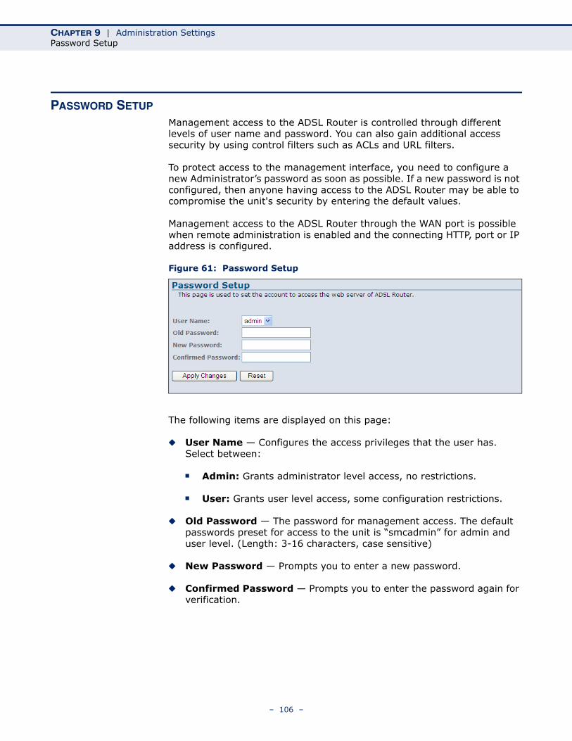
CHAPTER 9 | Administration SettingsPassword Setup
PASSWORD SETUP
Management access to the ADSL Router is controlled through different levels of user name and password. You can also gain additional access security by using control filters such as ACLs and URL filters.
To protect access to the management interface, you need to configure a new Administrator’s password as soon as possible. If a new password is not configured, then anyone having access to the ADSL Router may be able to compromise the unit's security by entering the default values.
Management access to the ADSL Router through the WAN port is possible when remote administration is enabled and the connecting HTTP, port or IP address is configured.
Figure 61: Password Setup
The following items are displayed on this page:
◆ User Name — Configures the access privileges that the user has. Select between:
■ Admin: Grants administrator level access, no restrictions.
■ User: Grants user level access, some configuration restrictions.
◆ Old Password — The password for management access. The default passwords preset for access to the unit is “smcadmin” for admin and user level. (Length: 3-16 characters, case sensitive)
◆ New Password — Prompts you to enter a new password.
◆ Confirmed Password — Prompts you to enter the password again for verification.
– 106 –
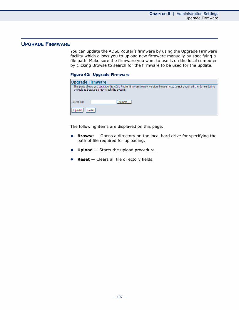
CHAPTER 9 | Administration SettingsUpgrade Firmware
UPGRADE FIRMWARE
You can update the ADSL Router’s firmware by using the Upgrade Firmware facility which allows you to upload new firmware manually by specifying a file path. Make sure the firmware you want to use is on the local computer by clicking Browse to search for the firmware to be used for the update.
Figure 62: Upgrade Firmware
The following items are displayed on this page:
◆ Browse — Opens a directory on the local hard drive for specifying the path of file required for uploading.
◆ Upload — Starts the upload procedure.
◆ Reset — Clears all file directory fields.
– 107 –
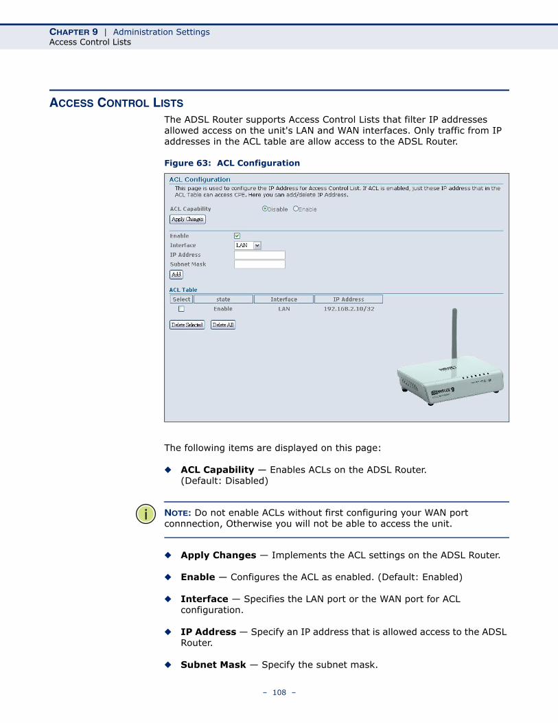
CHAPTER 9 | Administration SettingsAccess Control Lists
ACCESS CONTROL LISTS
The ADSL Router supports Access Control Lists that filter IP addresses allowed access on the unit's LAN and WAN interfaces. Only traffic from IP addresses in the ACL table are allow access to the ADSL Router.
Figure 63: ACL Configuration
The following items are displayed on this page:
◆ ACL Capability — Enables ACLs on the ADSL Router. (Default: Disabled)
NOTE: Do not enable ACLs without first configuring your WAN port connnection, Otherwise you will not be able to access the unit.
◆ Apply Changes — Implements the ACL settings on the ADSL Router.
◆ Enable — Configures the ACL as enabled. (Default: Enabled)
◆ Interface — Specifies the LAN port or the WAN port for ACL configuration.
◆ IP Address — Specify an IP address that is allowed access to the ADSL Router.
◆ Subnet Mask — Specify the subnet mask.
– 108 –
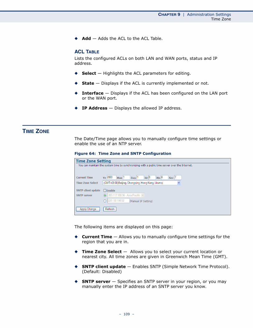
CHAPTER 9 | Administration SettingsTime Zone
◆ Add — Adds the ACL to the ACL Table.
ACL TABLE
Lists the configured ACLs on both LAN and WAN ports, status and IP address.
◆ Select — Highlights the ACL parameters for editing.
◆ State — Displays if the ACL is currently implemented or not.
◆ Interface — Displays if the ACL has been configured on the LAN port or the WAN port.
◆ IP Address — Displays the allowed IP address.
TIME ZONE
The Date/Time page allows you to manually configure time settings or enable the use of an NTP server.
Figure 64: Time Zone and SNTP Configuration
The following items are displayed on this page:
◆ Current Time — Allows you to manually configure time settings for the region that you are in.
◆ Time Zone Select — Allows you to select your current location or nearest city. All time zones are given in Greenwich Mean Time (GMT).
◆ SNTP client update — Enables SNTP (Simple Network Time Protocol). (Default: Disabled)
◆ SNTP server — Specifies an SNTP server in your region, or you may manually enter the IP address of an SNTP server you know.
– 109 –
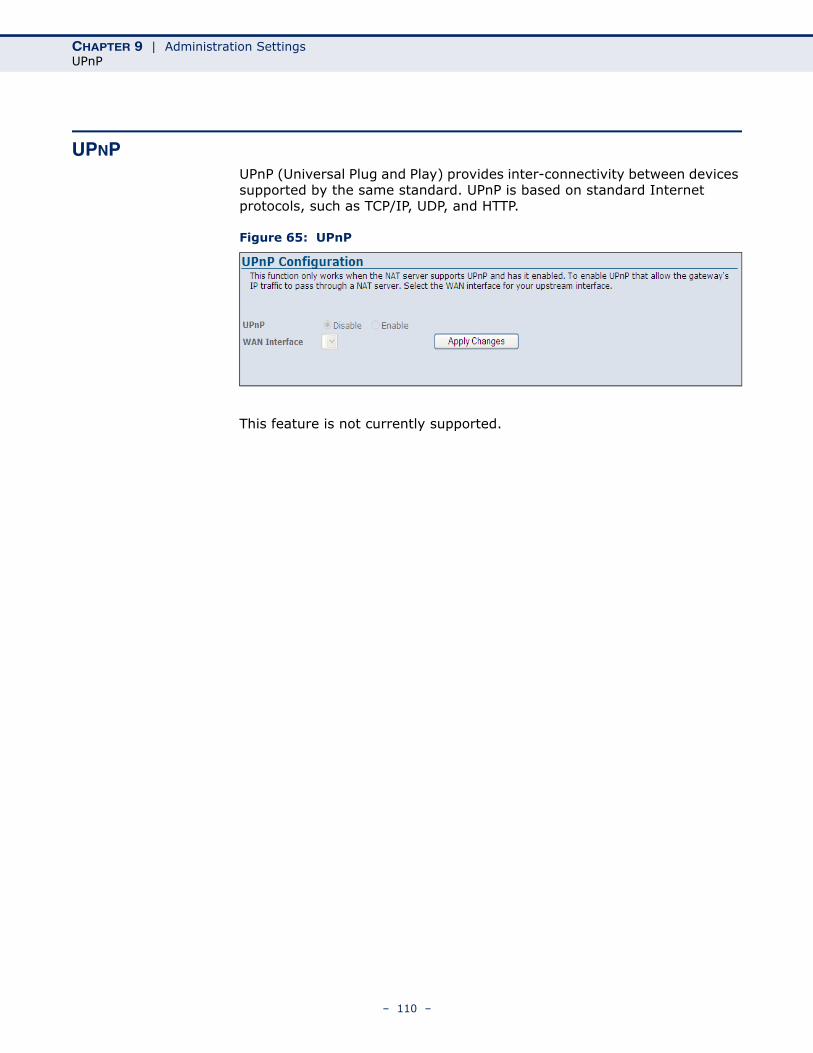
CHAPTER 9 | Administration SettingsUPnP
UPNPUPnP (Universal Plug and Play) provides inter-connectivity between devices supported by the same standard. UPnP is based on standard Internet protocols, such as TCP/IP, UDP, and HTTP.
Figure 65: UPnP
This feature is not currently supported.
– 110 –
10 ADVANCED CONFIGURATION
The Advanced Configuration settings for the ADSL Router contain advanced system management configuration settings such as DNS setup, routing configuration, bridging, SNMP and TR-069 settings.
The following sections are contained in this chapter:
◆ “DNS Server” on page 112
◆ “DDNS” on page 113
◆ “Routing Configuration” on page 115
◆ “RIP Configuration” on page 117
◆ “IP QoS” on page 118
◆ “IGMP Proxy Configuration” on page 120
◆ “Bridge Configuration” on page 121
◆ “IP Passthrough” on page 122
◆ “SNMP Protocol Configuration” on page 123
◆ “TR-069 Configuration” on page 124
– 111 –
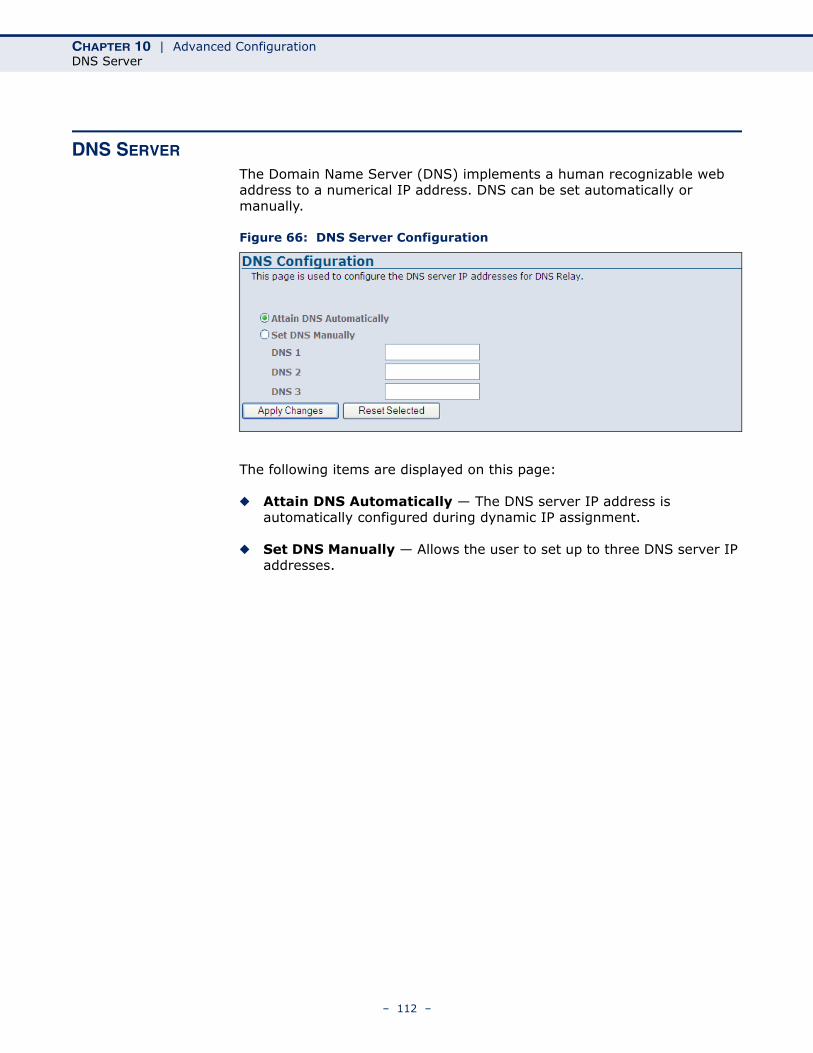
CHAPTER 10 | Advanced ConfigurationDNS Server
DNS SERVER
The Domain Name Server (DNS) implements a human recognizable web address to a numerical IP address. DNS can be set automatically or manually.
Figure 66: DNS Server Configuration
The following items are displayed on this page:
◆ Attain DNS Automatically — The DNS server IP address is automatically configured during dynamic IP assignment.
◆ Set DNS Manually — Allows the user to set up to three DNS server IP addresses.
– 112 –
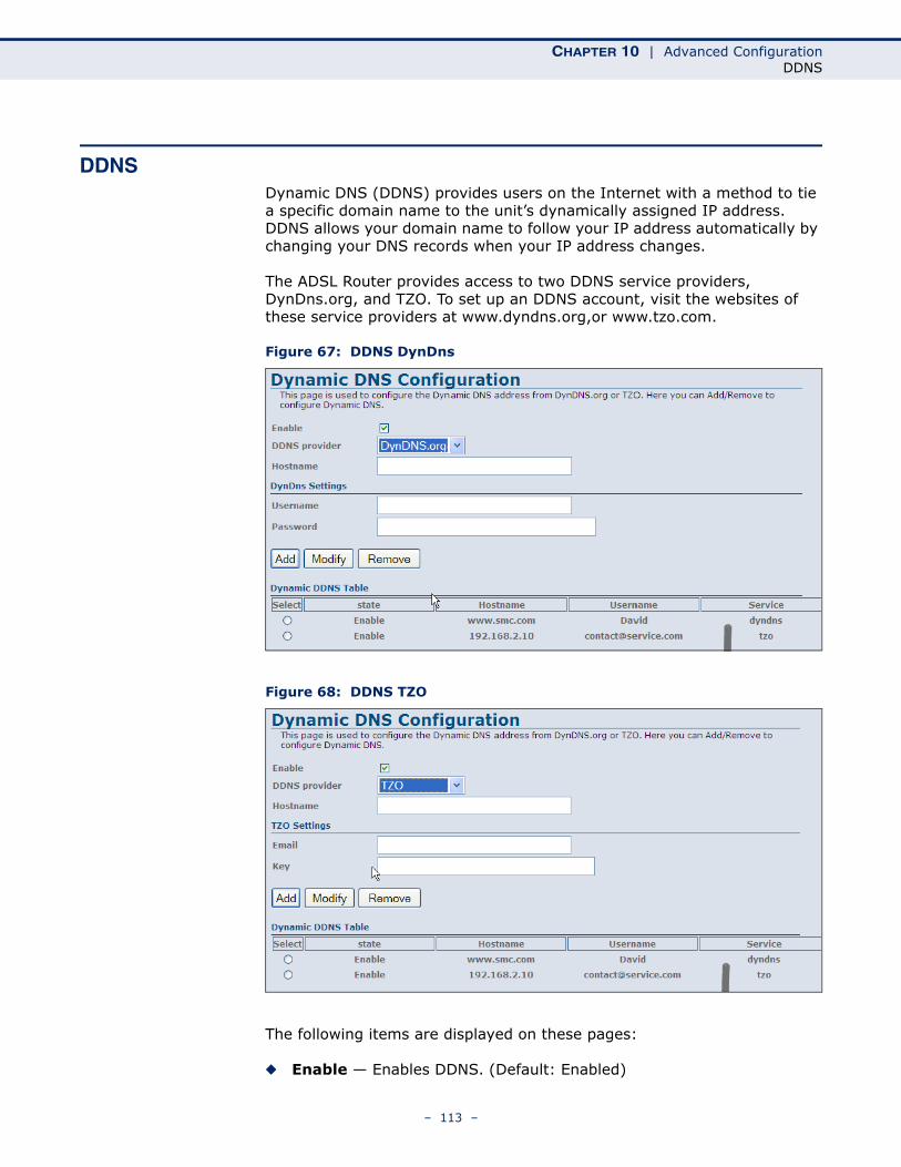
CHAPTER 10 | Advanced ConfigurationDDNS
DDNSDynamic DNS (DDNS) provides users on the Internet with a method to tie a specific domain name to the unit’s dynamically assigned IP address. DDNS allows your domain name to follow your IP address automatically by changing your DNS records when your IP address changes.
The ADSL Router provides access to two DDNS service providers, DynDns.org, and TZO. To set up an DDNS account, visit the websites of these service providers at www.dyndns.org,or www.tzo.com.
Figure 67: DDNS DynDns
Figure 68: DDNS TZO
The following items are displayed on these pages:
◆ Enable — Enables DDNS. (Default: Enabled)
– 113 –
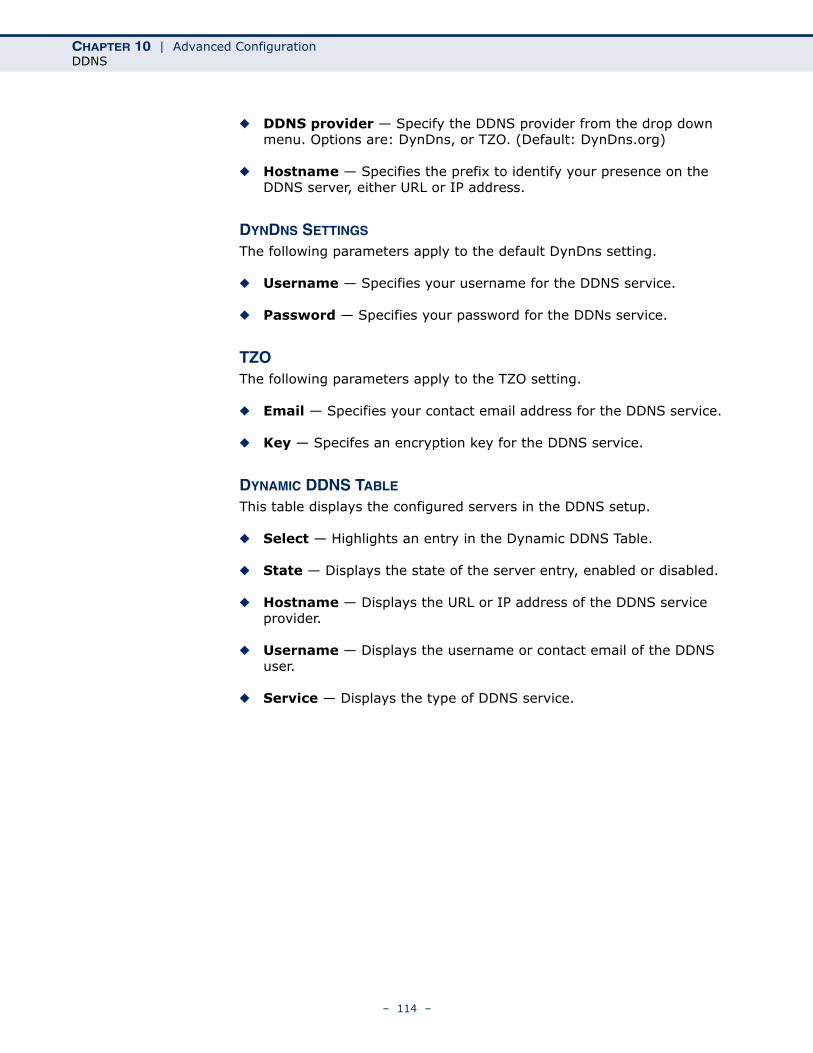
CHAPTER 10 | Advanced ConfigurationDDNS
◆ DDNS provider — Specify the DDNS provider from the drop down menu. Options are: DynDns, or TZO. (Default: DynDns.org)
◆ Hostname — Specifies the prefix to identify your presence on the DDNS server, either URL or IP address.
DYNDNS SETTINGS
The following parameters apply to the default DynDns setting.
◆ Username — Specifies your username for the DDNS service.
◆ Password — Specifies your password for the DDNs service.
TZOThe following parameters apply to the TZO setting.
◆ Email — Specifies your contact email address for the DDNS service.
◆ Key — Specifes an encryption key for the DDNS service.
DYNAMIC DDNS TABLE
This table displays the configured servers in the DDNS setup.
◆ Select — Highlights an entry in the Dynamic DDNS Table.
◆ State — Displays the state of the server entry, enabled or disabled.
◆ Hostname — Displays the URL or IP address of the DDNS service provider.
◆ Username — Displays the username or contact email of the DDNS user.
◆ Service — Displays the type of DDNS service.
– 114 –
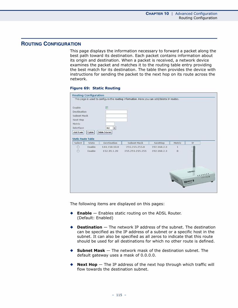
CHAPTER 10 | Advanced ConfigurationRouting Configuration
ROUTING CONFIGURATION
This page displays the information necessary to forward a packet along the best path toward its destination. Each packet contains information about its origin and destination. When a packet is received, a network device examines the packet and matches it to the routing table entry providing the best match for its destination. The table then provides the device with instructions for sending the packet to the next hop on its route across the network.
Figure 69: Static Routing
The following items are displayed on this pages:
◆ Enable — Enables static routing on the ADSL Router. (Default: Enabled)
◆ Destination — The network IP address of the subnet. The destination can be specified as the IP address of a subnet or a specific host in the subnet. It can also be specified as all zeros to indicate that this route should be used for all destinations for which no other route is defined.
◆ Subnet Mask — The network mask of the destination subnet. The default gateway uses a mask of 0.0.0.0.
◆ Next Hop — The IP address of the next hop through which traffic will flow towards the destination subnet.
– 115 –
CHAPTER 10 | Advanced ConfigurationRouting Configuration
◆ Metric — Defines the number of hops between network nodes that data packets travel. The default value is 0, which means that the subnet is directly one hop away on the local LAN network.
◆ Interface — The WAN interface to which a static routing subnet is to be applied.
◆ Add Route — Adds a static route to the Static Route Table.
◆ Update — Clears the above fields.
◆ Delete Selected — Deletes the specified static route.
STATIC ROUTE TABLE
This table displays all the configured static routes.
◆ Select — Highlights an entry in the Static Route Table.
◆ State — Displays if the route is enabled or disabled.
◆ Destination — Displays the final destination of the routed packets.
◆ Subnet Mask — Displays the subnet mask.
◆ Next Hop — The next hop that the packets will be routed to on their way to their final destination.
◆ Metric — Displays the number of hops from router to router that the packets must make before reaching their final destination.
◆ IF — Displays the interface the packets will be routed on.
– 116 –
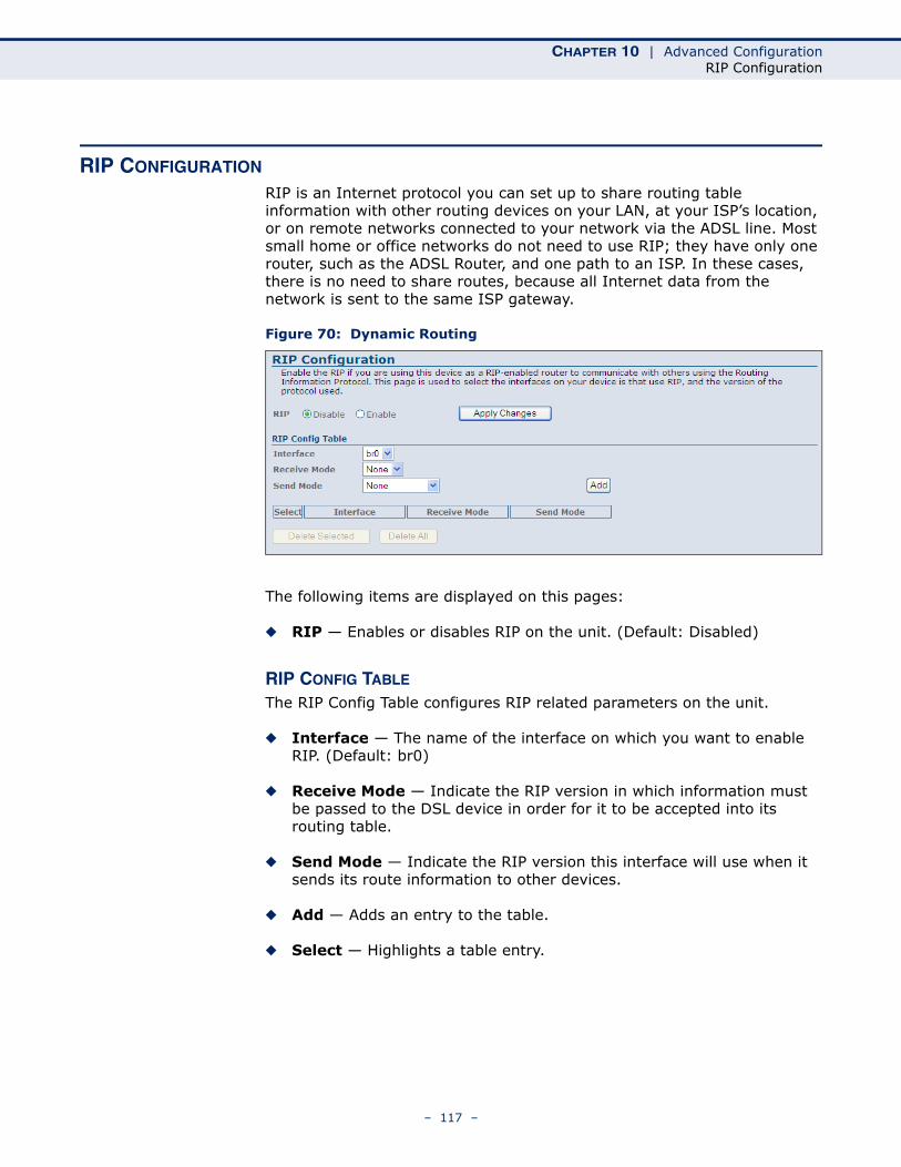
CHAPTER 10 | Advanced ConfigurationRIP Configuration
RIP CONFIGURATION
RIP is an Internet protocol you can set up to share routing table information with other routing devices on your LAN, at your ISP’s location, or on remote networks connected to your network via the ADSL line. Most small home or office networks do not need to use RIP; they have only one router, such as the ADSL Router, and one path to an ISP. In these cases, there is no need to share routes, because all Internet data from the network is sent to the same ISP gateway.
Figure 70: Dynamic Routing
The following items are displayed on this pages:
◆ RIP — Enables or disables RIP on the unit. (Default: Disabled)
RIP CONFIG TABLE
The RIP Config Table configures RIP related parameters on the unit.
◆ Interface — The name of the interface on which you want to enable RIP. (Default: br0)
◆ Receive Mode — Indicate the RIP version in which information must be passed to the DSL device in order for it to be accepted into its routing table.
◆ Send Mode — Indicate the RIP version this interface will use when it sends its route information to other devices.
◆ Add — Adds an entry to the table.
◆ Select — Highlights a table entry.
– 117 –
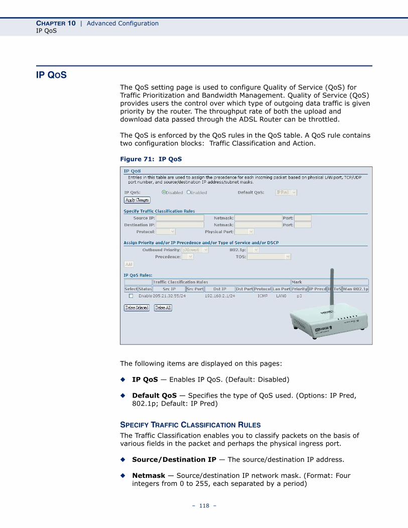
CHAPTER 10 | Advanced ConfigurationIP QoS
IP QOSThe QoS setting page is used to configure Quality of Service (QoS) for Traffic Prioritization and Bandwidth Management. Quality of Service (QoS) provides users the control over which type of outgoing data traffic is given priority by the router. The throughput rate of both the upload and download data passed through the ADSL Router can be throttled.
The QoS is enforced by the QoS rules in the QoS table. A QoS rule contains two configuration blocks: Traffic Classification and Action.
Figure 71: IP QoS
The following items are displayed on this pages:
◆ IP QoS — Enables IP QoS. (Default: Disabled)
◆ Default QoS — Specifies the type of QoS used. (Options: IP Pred, 802.1p; Default: IP Pred)
SPECIFY TRAFFIC CLASSIFICATION RULES
The Traffic Classification enables you to classify packets on the basis of various fields in the packet and perhaps the physical ingress port.
◆ Source/Destination IP — The source/destination IP address.
◆ Netmask — Source/destination IP network mask. (Format: Four integers from 0 to 255, each separated by a period)
– 118 –
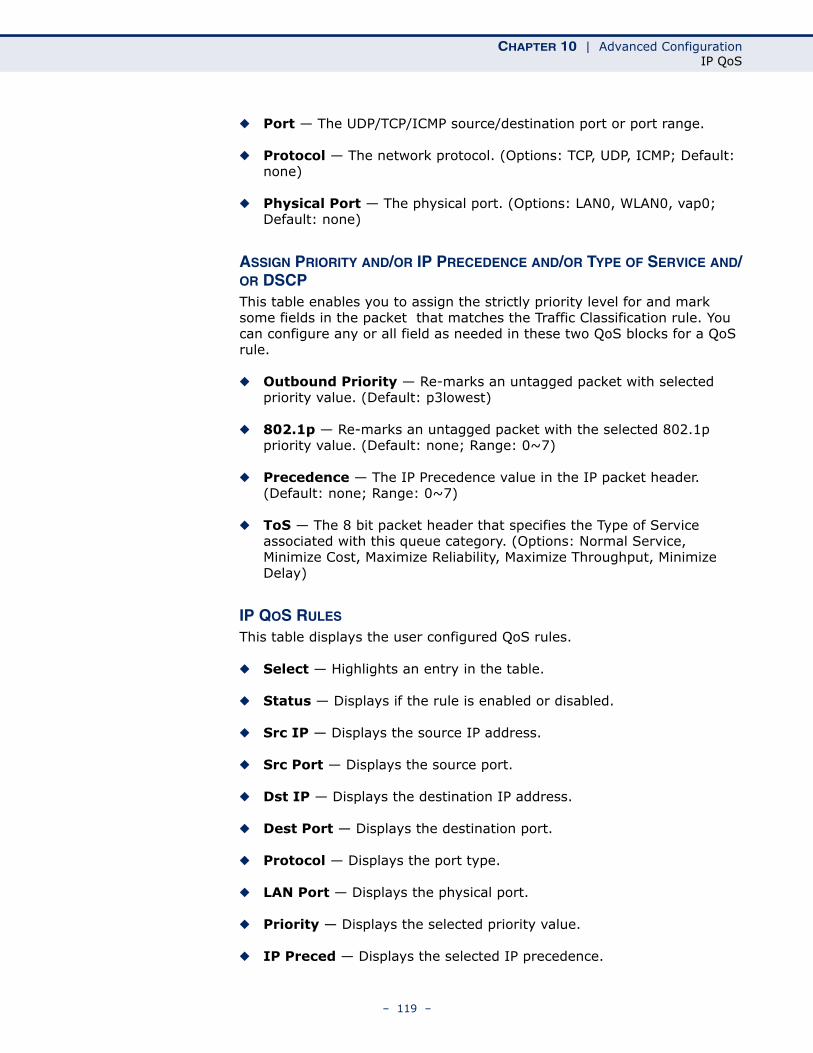
CHAPTER 10 | Advanced ConfigurationIP QoS
◆ Port — The UDP/TCP/ICMP source/destination port or port range.
◆ Protocol — The network protocol. (Options: TCP, UDP, ICMP; Default: none)
◆ Physical Port — The physical port. (Options: LAN0, WLAN0, vap0; Default: none)
ASSIGN PRIORITY AND/OR IP PRECEDENCE AND/OR TYPE OF SERVICE AND/OR DSCPThis table enables you to assign the strictly priority level for and mark some fields in the packet that matches the Traffic Classification rule. You can configure any or all field as needed in these two QoS blocks for a QoS rule.
◆ Outbound Priority — Re-marks an untagged packet with selected priority value. (Default: p3lowest)
◆ 802.1p — Re-marks an untagged packet with the selected 802.1p priority value. (Default: none; Range: 0~7)
◆ Precedence — The IP Precedence value in the IP packet header. (Default: none; Range: 0~7)
◆ ToS — The 8 bit packet header that specifies the Type of Service associated with this queue category. (Options: Normal Service, Minimize Cost, Maximize Reliability, Maximize Throughput, Minimize Delay)
IP QOS RULES
This table displays the user configured QoS rules.
◆ Select — Highlights an entry in the table.
◆ Status — Displays if the rule is enabled or disabled.
◆ Src IP — Displays the source IP address.
◆ Src Port — Displays the source port.
◆ Dst IP — Displays the destination IP address.
◆ Dest Port — Displays the destination port.
◆ Protocol — Displays the port type.
◆ LAN Port — Displays the physical port.
◆ Priority — Displays the selected priority value.
◆ IP Preced — Displays the selected IP precedence.
– 119 –
CHAPTER 10 | Advanced ConfigurationIGMP Proxy Configuration
◆ IP ToS — Displays the selected IP Type of Service.
◆ WAN 802.1p — Displays the 802.1p value associated with the WAN port.
IGMP PROXY CONFIGURATION
Multicasting is useful when the same data needs to be sent to more than one host. Using multicasting as opposed to sending the same data to the individual hosts uses less network bandwidth. The multicast feature also enables you to receive multicast video stream from multicast servers.
IP hosts use Internet Group Management Protocol (IGMP) to report their multicast group memberships to neighboring routers. Similarly, multicast routers use IGMP to discover which of their hosts belong to multicast groups. This device supports IGMP proxy that handles IGMP messages. When enabled, this device acts as a proxy for a LAN host making requests to join and leave multicast groups, or a multicast router sending multicast packets to multicast group on the WAN side.
Figure 72: IGMP Configuration
The following items are displayed on this pages:
◆ IGMP Proxy — Enables IGMP proxy. When enabled, the upstream interface acts as a host interface, sending query messages periodically to the downstream interfaces, sending join and leave messages to the upstream multicast router when a first join or last leave message is received from a downstream interface, and sending membership reports in response to query messages from the multicast router.
◆ Proxy Interface — Specifies the upstream WAN interface on which to implement IGMP proxy.
NOTE: The IGMP Proxy feature is not supported in the current software release.
– 120 –

CHAPTER 10 | Advanced ConfigurationBridge Configuration
BRIDGE CONFIGURATION
This feature allows you to set the bridge aging time and to enable Spanning Tree.
The Spanning Tree Protocol (STP) can be used to detect and disable network loops, and to provide backup links between bridges. This allows a wireless bridge to interact with other bridging devices (that is, an STP-compliant switch, bridge or router) in your network to ensure that only one route exists between any two stations on the network, and provide backup links which automatically take over when a primary link goes down.
Figure 73: Bridge Configuration
The following items are displayed on this pages:
◆ Ageing Time — Sets the MAC address ageing time, in seconds. After the aging time has been reached with no traffic received, the unit will delete the address from the forwarding database. (Default: 300 seconds)
◆ 802.1d Spanning Tree — Enables/disables the Spanning Tree Protocol on the ADSL Router. (Default: Disabled)
– 121 –
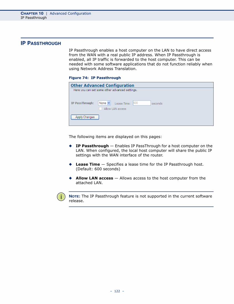
CHAPTER 10 | Advanced ConfigurationIP Passthrough
IP PASSTHROUGH
IP Passthrough enables a host computer on the LAN to have direct access from the WAN with a real public IP address. When IP Passthrough is enabled, all IP traffic is forwarded to the host computer. This can be needed with some software applications that do not function reliably when using Network Address Translation.
Figure 74: IP Passthrough
The following items are displayed on this pages:
◆ IP Passthrough — Enables IP PassThrough for a host computer on the LAN. When configured, the local host computer will share the public IP settings with the WAN interface of the router.
◆ Lease Time — Specifies a lease time for the IP Passthrough host. (Default: 600 seconds)
◆ Allow LAN access — Allows access to the host computer from the attached LAN.
NOTE: The IP Passthrough feature is not supported in the current software release.
– 122 –
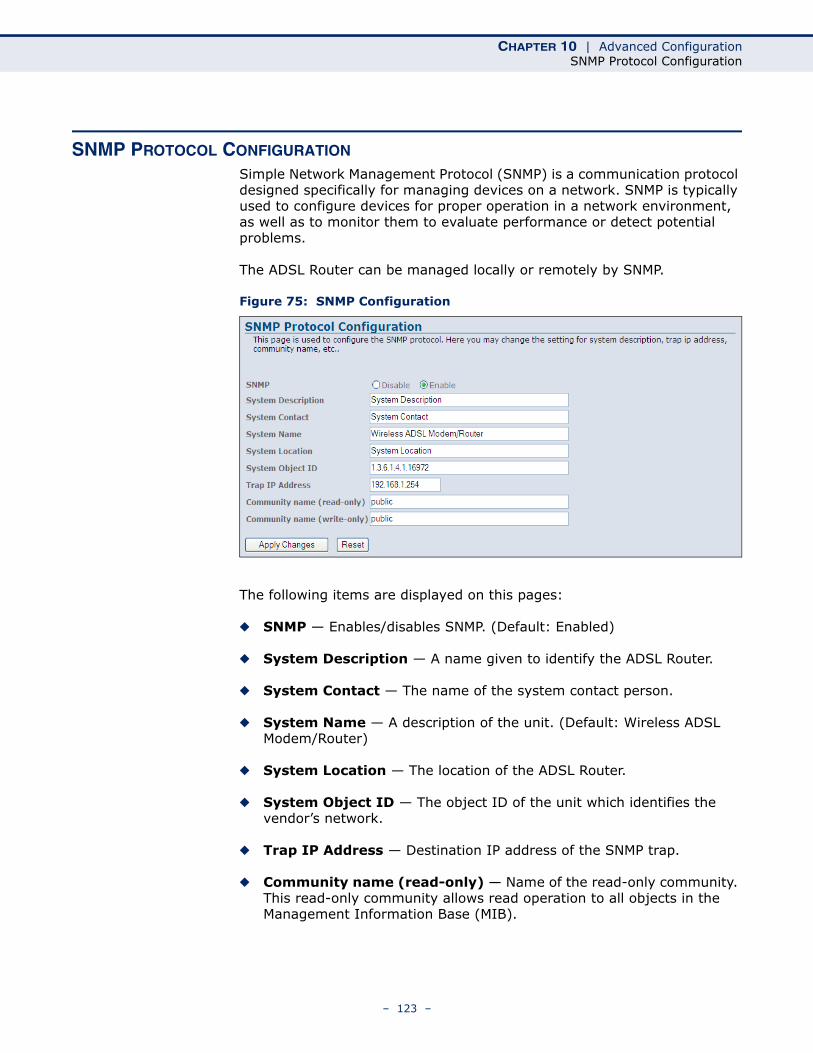
CHAPTER 10 | Advanced ConfigurationSNMP Protocol Configuration
SNMP PROTOCOL CONFIGURATION
Simple Network Management Protocol (SNMP) is a communication protocol designed specifically for managing devices on a network. SNMP is typically used to configure devices for proper operation in a network environment, as well as to monitor them to evaluate performance or detect potential problems.
The ADSL Router can be managed locally or remotely by SNMP.
Figure 75: SNMP Configuration
The following items are displayed on this pages:
◆ SNMP — Enables/disables SNMP. (Default: Enabled)
◆ System Description — A name given to identify the ADSL Router.
◆ System Contact — The name of the system contact person.
◆ System Name — A description of the unit. (Default: Wireless ADSL Modem/Router)
◆ System Location — The location of the ADSL Router.
◆ System Object ID — The object ID of the unit which identifies the vendor’s network.
◆ Trap IP Address — Destination IP address of the SNMP trap.
◆ Community name (read-only) — Name of the read-only community. This read-only community allows read operation to all objects in the Management Information Base (MIB).
– 123 –
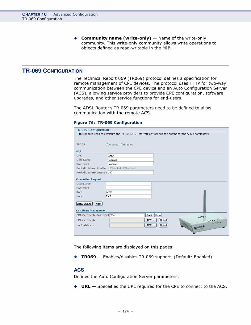
CHAPTER 10 | Advanced ConfigurationTR-069 Configuration
◆ Community name (write-only) — Name of the write-only community. This write-only community allows write operations to objects defined as read-writable in the MIB.
TR-069 CONFIGURATION
The Technical Report 069 (TR069) protocol defines a specification for remote management of CPE devices. The protocol uses HTTP for two-way communication between the CPE device and an Auto Configuration Server (ACS), allowing service providers to provide CPE configuration, software upgrades, and other service functions for end-users.
The ADSL Router’s TR-069 parameters need to be defined to allow communication with the remote ACS.
Figure 76: TR-069 Configuration
The following items are displayed on this pages:
◆ TR069 — Enables/disables TR-069 support. (Default: Enabled)
ACSDefines the Auto Configuration Server parameters.
◆ URL — Speceifies the URL required for the CPE to connect to the ACS.
– 124 –
CHAPTER 10 | Advanced ConfigurationTR-069 Configuration
◆ Username — Enter the user name that the ADSL Router should use when connecting to the ACS.
◆ Password — Enter the password that the ADSL Router should use when connecting to the ACS.
◆ Periodic Inform Enable — When this field is enabled, the DSL device will send an Inform RPC to the ACS server at the system startup, and will continue to send it periodically at an interval defined in Periodic Inform Interval field; When this field is disabled, the DSL device will only send Inform RPC to the ACS server once at the system startup. (Default: Enabled)
◆ Periodic Inform Interval — Time interval in seconds to send Inform RPC.
CONNECTION REQUEST
Defines the connection from the ADSL Router to the ACS.
◆ User Name — The user name the remote ACS should use when connecting to this device.
◆ Password — The password the remote ACS should use when connecting to this device.
◆ Path — The path of the device ConnectionRequestURL. The device ConnectionRequestURL should be configured based on the Device_IP, Path and Port as follows: http://Device_IP:Port/Path
◆ Port — The port of the device ConnectionRequestURL.
CERTIFICATE MANAGEMENT
Defines the digital certificate files used for authentication between the ADSL Router and the ACS.
◆ CPE Certificate Password — The password to use with the ADSL Router's digital certificate file.
◆ CPE Certificate — The unique digital security certificate used by the ADSL Router to authenticate with the ACS server. Click the “Browse” button to locate the file on your local PC and upload it to the unit using the “Upload” button.
◆ CA Certificate — The digital security certificate issued by a Certified Authority to be used by the unit when authenticating the ACS server. Click the “Browse” button to locate the file on your local PC and upload it to the unit using the “Upload” button.
– 125 –

CHAPTER 10 | Advanced ConfigurationTR-069 Configuration
– 126 –
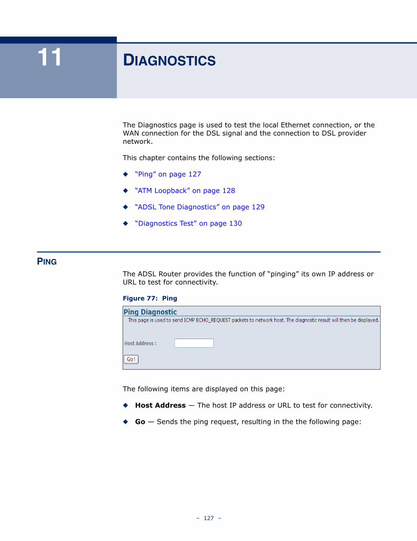
11 DIAGNOSTICS
The Diagnostics page is used to test the local Ethernet connection, or the WAN connection for the DSL signal and the connection to DSL provider network.
This chapter contains the following sections:
◆ “Ping” on page 127
◆ “ATM Loopback” on page 128
◆ “ADSL Tone Diagnostics” on page 129
◆ “Diagnostics Test” on page 130
PING
The ADSL Router provides the function of “pinging” its own IP address or URL to test for connectivity.
Figure 77: Ping
The following items are displayed on this page:
◆ Host Address — The host IP address or URL to test for connectivity.
◆ Go — Sends the ping request, resulting in the the following page:
– 127 –
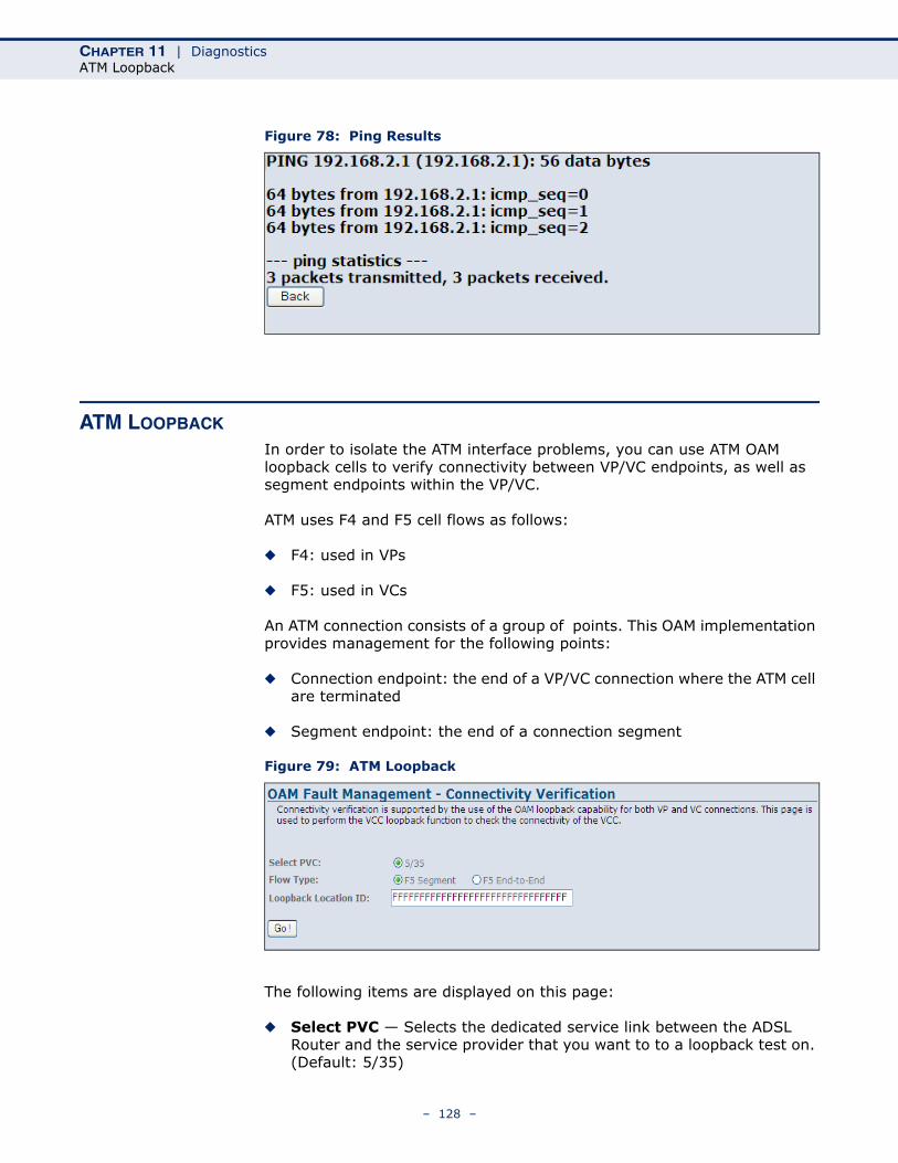
CHAPTER 11 | DiagnosticsATM Loopback
Figure 78: Ping Results
ATM LOOPBACK
In order to isolate the ATM interface problems, you can use ATM OAM loopback cells to verify connectivity between VP/VC endpoints, as well as segment endpoints within the VP/VC.
ATM uses F4 and F5 cell flows as follows:
◆ F4: used in VPs
◆ F5: used in VCs
An ATM connection consists of a group of points. This OAM implementation provides management for the following points:
◆ Connection endpoint: the end of a VP/VC connection where the ATM cell are terminated
◆ Segment endpoint: the end of a connection segment
Figure 79: ATM Loopback
The following items are displayed on this page:
◆ Select PVC — Selects the dedicated service link between the ADSL Router and the service provider that you want to to a loopback test on. (Default: 5/35)
– 128 –
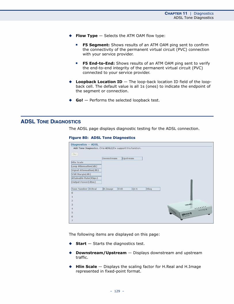
CHAPTER 11 | DiagnosticsADSL Tone Diagnostics
◆ Flow Type — Selects the ATM OAM flow type:
■ F5 Segment: Shows results of an ATM OAM ping sent to confirm the connectivity of the permanent virtual circuit (PVC) connection with your service provider.
■ F5 End-to-End: Shows results of an ATM OAM ping sent to verify the end-to-end integrity of the permanent virtual circuit (PVC) connected to your service provider.
◆ Loopback Location ID — The loop-back location ID field of the loop-back cell. The default value is all 1s (ones) to indicate the endpoint of the segment or connection.
◆ Go! — Performs the selected loopback test.
ADSL TONE DIAGNOSTICS
The ADSL page displays diagnostic testing for the ADSL connection.
Figure 80: ADSL Tone Diagnostics
The following items are displayed on this page:
◆ Start — Starts the diagnostics test.
◆ Downstream/Upstream — Displays downstream and upstream traffic.
◆ Hlin Scale — Displays the scaling factor for H.Real and H.Image represented in fixed-point format.
– 129 –
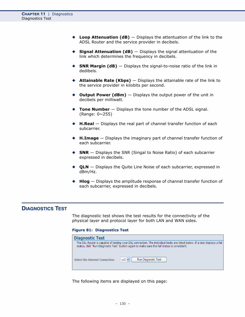
CHAPTER 11 | DiagnosticsDiagnostics Test
◆ Loop Attenuation (dB) — Displays the attentuation of the link to the ADSL Router and the service provider in decibels.
◆ Signal Attenuation (dB) — Displays the signal attentuation of the link which determines the frequency in decibels.
◆ SNR Margin (dB) — Displays the signal-to-noise ratio of the link in dedibels.
◆ Attainable Rate (Kbps) — Displays the attainable rate of the link to the service provider in kilobits per second.
◆ Output Power (dBm) — Displays the output power of the unit in decibels per milliwatt.
◆ Tone Number — Displays the tone number of the ADSL signal. (Range: 0~255)
◆ H.Real — Displays the real part of channel transfer function of each subcarrier.
◆ H.Image — Displays the imaginary part of channel transfer function of each subcarrier.
◆ SNR — Displays the SNR (Singal to Noise Ratio) of each subcarrier expressed in decibels.
◆ QLN — Displays the Quite Line Noise of each subcarrier, expressed in dBm/Hz.
◆ Hlog — Displays the amplitude response of channel transfer function of each subcarrier, expressed in decibels.
DIAGNOSTICS TEST
The diagnostic test shows the test results for the connectivity of the physical layer and protocol layer for both LAN and WAN sides.
Figure 81: Diagnostics Test
The following items are displayed on this page:
– 130 –
CHAPTER 11 | DiagnosticsDiagnostics Test
◆ Select Internet Connection — Selects the Internet connection. (Default: vc0)
◆ Run Diagnostic Test — Performs a diagnostic test on the LAN and WAN side connections.
LAN CONNECTION CHECK
Displays the result of a test for connectivity on the LAN port.
◆ Test Ethernet LAN Connection — Displays the connectivity of the Ethernet LAN port.
ADSL CONNECTION TEST
Displays the results of a test for connectivity on the WAN port.
◆ Test ADSL Synchronization — Displays the connectivity of the ADSL synchronisation.
◆ Test ATM OAM F5 Segment Loopback — Displays the connectivity of an F5 segment loopback of the permanent virtual circuit (PVC) connection with your service provider.
◆ Test ATM OAM F5 End-to-end Loopback — Displays the connectivity of an F5 end-to-end loopback integrity test of the permanent virtual circuit (PVC) connected to your service provider.
◆ Test ATM OAM F4 Segment Loopback — Displays the connectivity of an F4 segment loopback of the permanent virtual circuit (PVC) connection with your service provider.
◆ Test ATM OAM F4 End-to-end Loopback — Displays the connectivity of an F4 end-to-end loopback integrity test of the permanent virtual circuit (PVC) connected to your service provider.
– 131 –
SECTION III
APPENDICES
This section provides additional information and includes these items:
◆ “Troubleshooting” on page 133
◆ “Hardware Specifications” on page 137
◆ “Cables and Pinouts” on page 139
◆ “Glossary” on page 143
◆ “Index” on page 147
– 132 –
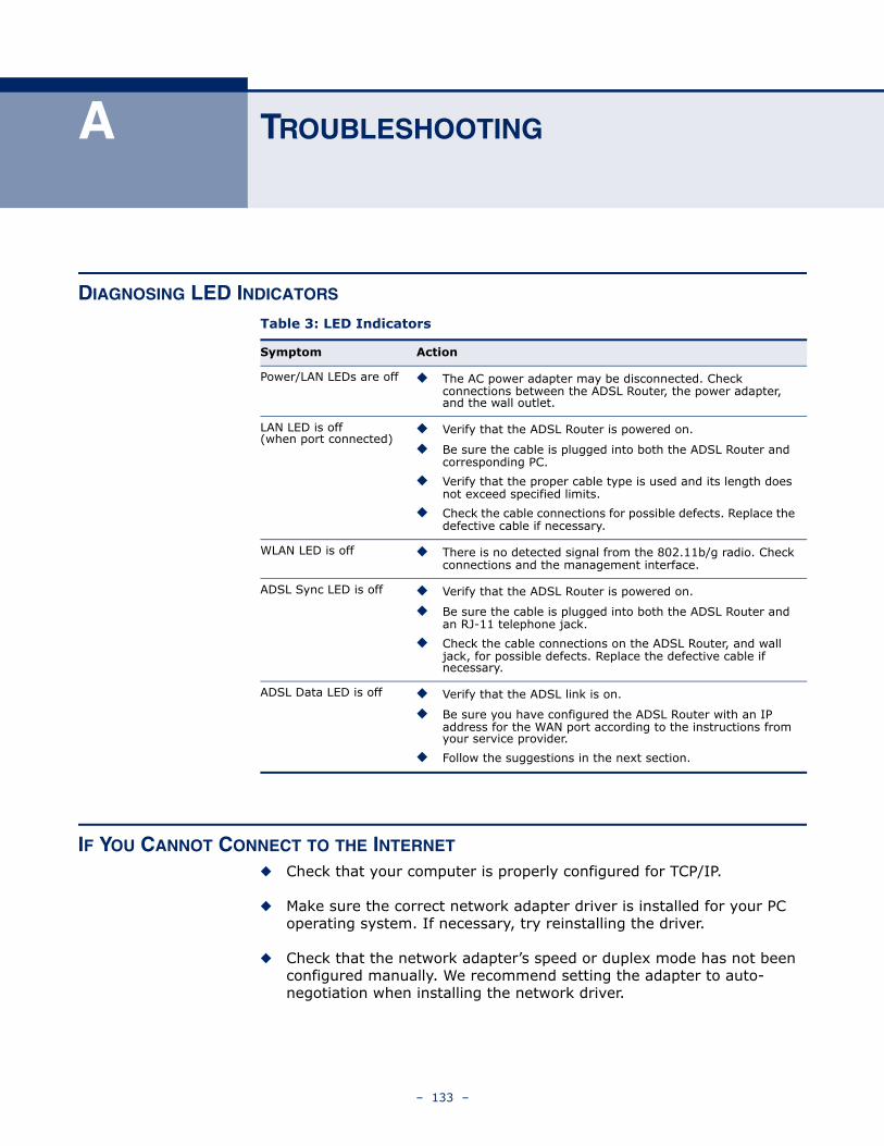
A TROUBLESHOOTING
DIAGNOSING LED INDICATORS
IF YOU CANNOT CONNECT TO THE INTERNET
◆ Check that your computer is properly configured for TCP/IP.
◆ Make sure the correct network adapter driver is installed for your PC operating system. If necessary, try reinstalling the driver.
◆ Check that the network adapter’s speed or duplex mode has not been configured manually. We recommend setting the adapter to auto-negotiation when installing the network driver.
Table 3: LED Indicators
Symptom Action
Power/LAN LEDs are off ◆ The AC power adapter may be disconnected. Check connections between the ADSL Router, the power adapter, and the wall outlet.
LAN LED is off (when port connected)
◆ Verify that the ADSL Router is powered on.
◆ Be sure the cable is plugged into both the ADSL Router and corresponding PC.
◆ Verify that the proper cable type is used and its length does not exceed specified limits.
◆ Check the cable connections for possible defects. Replace the defective cable if necessary.
WLAN LED is off ◆ There is no detected signal from the 802.11b/g radio. Check connections and the management interface.
ADSL Sync LED is off ◆ Verify that the ADSL Router is powered on.
◆ Be sure the cable is plugged into both the ADSL Router and an RJ-11 telephone jack.
◆ Check the cable connections on the ADSL Router, and wall jack, for possible defects. Replace the defective cable if necessary.
ADSL Data LED is off ◆ Verify that the ADSL link is on.
◆ Be sure you have configured the ADSL Router with an IP address for the WAN port according to the instructions from your service provider.
◆ Follow the suggestions in the next section.
– 133 –
APPENDIX A | TroubleshootingBefore Contacting Technical Support
BEFORE CONTACTING TECHNICAL SUPPORT
Check the following items before you contact local Technical Support.
1. If wireless clients cannot access the network, check the following:
■ Be sure the ADSL Router and the wireless clients are configured with the same Service Set ID (SSID).
■ If authentication or encryption are enabled, ensure that the wireless clients are properly configured with the appropriate authentication or encryption keys.
■ If authentication is being performed through a RADIUS server, ensure that the clients are properly configured on the RADIUS server.
■ If authentication is being performed through IEEE 802.1X, be sure the wireless users have installed and properly configured 802.1X client software.
■ If MAC address filtering is enabled, be sure the client’s address is included in the local filtering database or on the RADIUS server database.
■ If the wireless clients are roaming between ADSL Routers, make sure that all the ADSL Routers and wireless devices in the Extended Service Set (ESS) are configured to the same SSID, and authentication method.
2. If the ADSL Router cannot be configured using the Telnet, a web browser, or SNMP software:
■ Be sure to have configured the ADSL Router with a valid IP address, subnet mask and default gateway.
■ Check that you have a valid network connection to the ADSL Router and that the Ethernet port or the wireless interface that you are using has not been disabled.
■ If you are connecting to the ADSL Router through the wired Ethernet interface, check the network cabling between the management station and the ADSL Router. If you are connecting to ADSL Router from a wireless client, ensure that you have a valid connection to the ADSL Router.
■ If you cannot connect using Telnet, you may have exceeded the maximum number of concurrent Telnet sessions permitted (i.e, four sessions). Try connecting again at a later time.
– 134 –
APPENDIX A | TroubleshootingBefore Contacting Technical Support
3. If you forgot or lost the password:
■ Set the ADSL Router to its default configuration by pressing the reset button on the back panel for 5 seconds or more. Then use the default user name “admin” and password “smcadmin” to access the management interface.
4. If all other recovery measure fail, and the ADSL Router is still not functioning properly, take any of these steps:
■ Reset the ADSL Router’s hardware using the web interface, or through a power reset.
■ Reset the ADSL Router to its default configuration by pressing the reset button on the back panel for 5 seconds or more. Then use the default user name “admin” and a null password to access the management interface.
– 135 –

APPENDIX A | TroubleshootingBefore Contacting Technical Support
– 136 –
B HARDWARE SPECIFICATIONS
WIRELESS TRANSMITPOWER (MAXIMUM)
802.11b/g:802.11b: 18 dBm (typical)802.11g: 13 dBm
WIRELESS RECEIVESENSITIVITY (MAXIMUM)
802.11b/g:802.11b: -85 dBm @ 1 Mbps; -80 dBm @ 11 Mbps802.11g: -83 dBm @ 6 Mbps; -66 dBm @ 54 Mbps
OPERATING FREQUENCY 802.11g:2.4 ~ 2.4835 GHz (US, Canada)2.4 ~ 2.4835 GHz (ETSI, Japan)802.11b:2.4 ~ 2.4835 GHz (US, Canada)2.4 ~ 2.4835 GHz (ETSI)2.4 ~ 2.497 GHz (Japan)
DATA RATE 802.11b: 1, 2, 5.5, 11 Mbps per channel802.11g: 6, 9, 12, 18, 24, 36, 48, 54 Mbps per channel
OPERATING CHANNELS 802.11g:11 channels in base mode (US, Canada)13 channels (ETSI, Japan)802.11b:11 channels in base mode (US, Canada)13 channels (ETSI)14 channels (Japan)
MODULATION TYPE 802.11g: CCK, BPSK, QPSK, OFDM802.11b: CCK, BPSK, QPSK
AC POWER ADAPTER Input: 100 or 240 VAC, 50-60 HzOutput: 12 V/0.5 A
– 137 –
APPENDIX B | Hardware Specifications
LED INDICATORS Power, WLAN (Wireless Local Area Network), LAN (Local Area Network), ADSL Sync, ADSL Data.
NETWORK MANAGEMENT Web-browser
TelnetSNMP
TEMPERATURE Operating: 0 to 40 °C (32 to 104 °F)Storage: -20 to 70 °C (32 to 158 °F)
HUMIDITY 20% to 85% (non-condensing)
COMPLIANCES FCC Part 15B, Part 68 Class B
CETELEPERMIT PTC 273/08/024A-Tick
RADIO SIGNALCERTIFICATION
FCC Part 15C 15.247, 15.207 (2.4 GHz)EN 300 328EN 301 489-1EN 301 489-17
STANDARDS IEEE 802.11b/g
ANSI T1.413 Issue 2G.992.1 (G.dmt) Annex A/L/MSupport ITU G.992.1 (G.dmt) Annex A,L,M simultaneous or support Annex B,L,M simultaneousG.992.2 (G.lite) Annex AG.992.4G.994.1 (G.hs)G.992.3 (ADSL2 G.dmt.bis) Annex A/L/MG.992.5 (ADSL2+) Annex A/L/MSupport up to 25 Mbps downstream and 3.5 Mbps upstream(*ADSL speed may vary depend on your individual contract with or service offered by your ISP and the distance from the ISP DSLAM.)
– 138 –
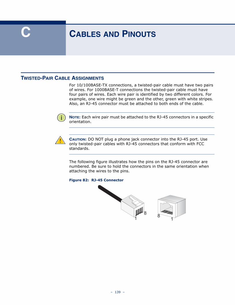
C CABLES AND PINOUTS
TWISTED-PAIR CABLE ASSIGNMENTS
For 10/100BASE-TX connections, a twisted-pair cable must have two pairs of wires. For 1000BASE-T connections the twisted-pair cable must have four pairs of wires. Each wire pair is identified by two different colors. For example, one wire might be green and the other, green with white stripes. Also, an RJ-45 connector must be attached to both ends of the cable.
NOTE: Each wire pair must be attached to the RJ-45 connectors in a specific orientation.
CAUTION: DO NOT plug a phone jack connector into the RJ-45 port. Use only twisted-pair cables with RJ-45 connectors that conform with FCC standards.
The following figure illustrates how the pins on the RJ-45 connector are numbered. Be sure to hold the connectors in the same orientation when attaching the wires to the pins.
Figure 82: RJ-45 Connector
811
8
– 139 –
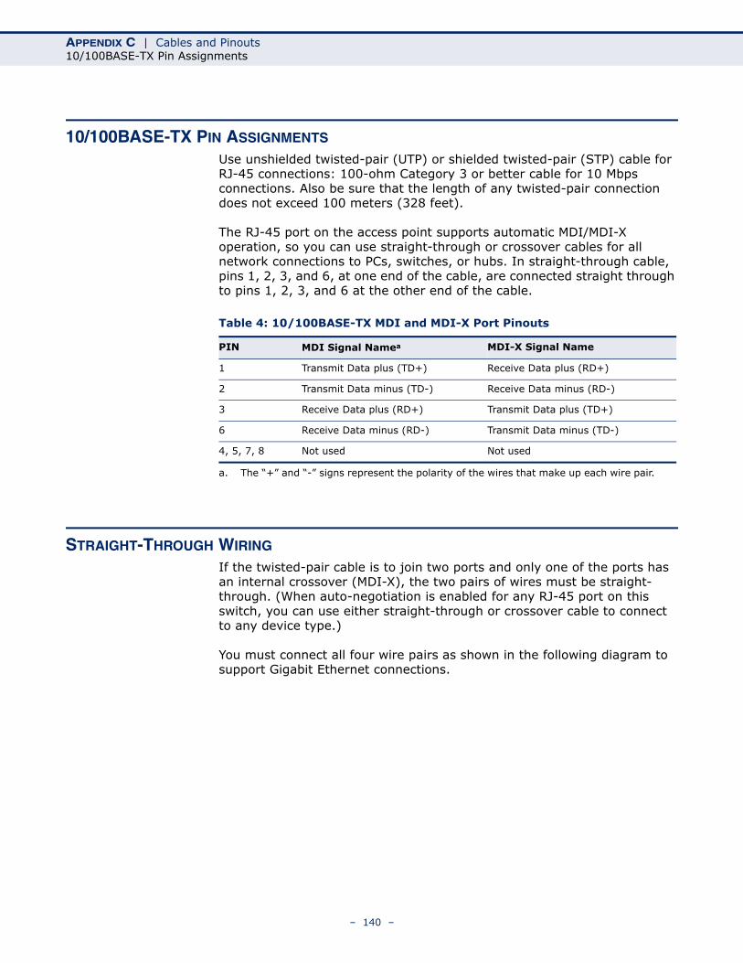
APPENDIX C | Cables and Pinouts10/100BASE-TX Pin Assignments
10/100BASE-TX PIN ASSIGNMENTS
Use unshielded twisted-pair (UTP) or shielded twisted-pair (STP) cable for RJ-45 connections: 100-ohm Category 3 or better cable for 10 Mbps connections. Also be sure that the length of any twisted-pair connection does not exceed 100 meters (328 feet).
The RJ-45 port on the access point supports automatic MDI/MDI-X operation, so you can use straight-through or crossover cables for all network connections to PCs, switches, or hubs. In straight-through cable, pins 1, 2, 3, and 6, at one end of the cable, are connected straight through to pins 1, 2, 3, and 6 at the other end of the cable.
STRAIGHT-THROUGH WIRING
If the twisted-pair cable is to join two ports and only one of the ports has an internal crossover (MDI-X), the two pairs of wires must be straight-through. (When auto-negotiation is enabled for any RJ-45 port on this switch, you can use either straight-through or crossover cable to connect to any device type.)
You must connect all four wire pairs as shown in the following diagram to support Gigabit Ethernet connections.
Table 4: 10/100BASE-TX MDI and MDI-X Port Pinouts
PIN MDI Signal Namea
a. The “+” and “-” signs represent the polarity of the wires that make up each wire pair.
MDI-X Signal Name
1 Transmit Data plus (TD+) Receive Data plus (RD+)
2 Transmit Data minus (TD-) Receive Data minus (RD-)
3 Receive Data plus (RD+) Transmit Data plus (TD+)
6 Receive Data minus (RD-) Transmit Data minus (TD-)
4, 5, 7, 8 Not used Not used
– 140 –
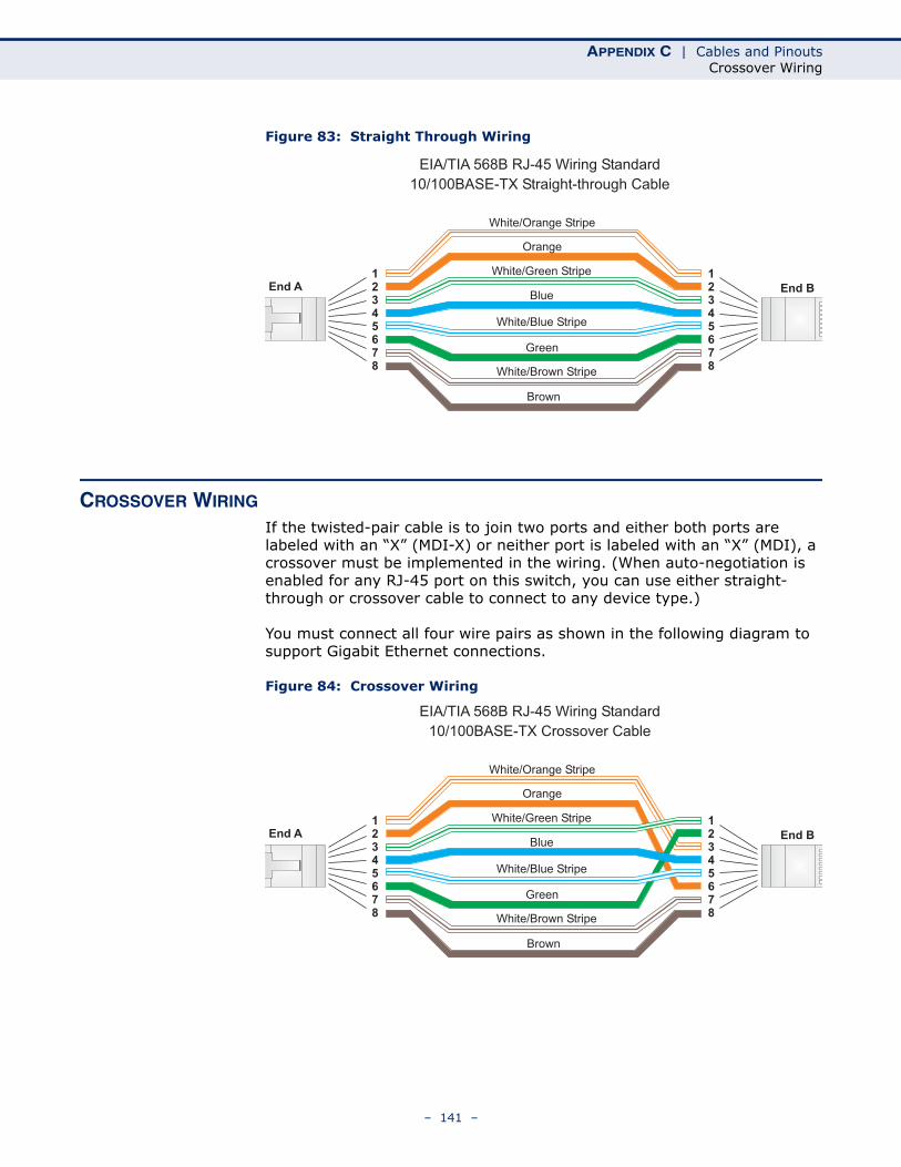
APPENDIX C | Cables and PinoutsCrossover Wiring
Figure 83: Straight Through Wiring
CROSSOVER WIRING
If the twisted-pair cable is to join two ports and either both ports are labeled with an “X” (MDI-X) or neither port is labeled with an “X” (MDI), a crossover must be implemented in the wiring. (When auto-negotiation is enabled for any RJ-45 port on this switch, you can use either straight-through or crossover cable to connect to any device type.)
You must connect all four wire pairs as shown in the following diagram to support Gigabit Ethernet connections.
Figure 84: Crossover Wiring
White/Orange Stripe
Orange
White/Green Stripe
Green
12345678
12345678
EIA/TIA 568B RJ-45 Wiring Standard
10/100BASE-TX Straight-through Cable
End A End BBlue
White/Blue Stripe
Brown
White/Brown Stripe
White/Orange Stripe
Orange
White/Green Stripe12345678
12345678
EIA/TIA 568B RJ-45 Wiring Standard
10/100BASE-TX Crossover Cable
End A End B
Green
Blue
White/Blue Stripe
Brown
White/Brown Stripe
– 141 –
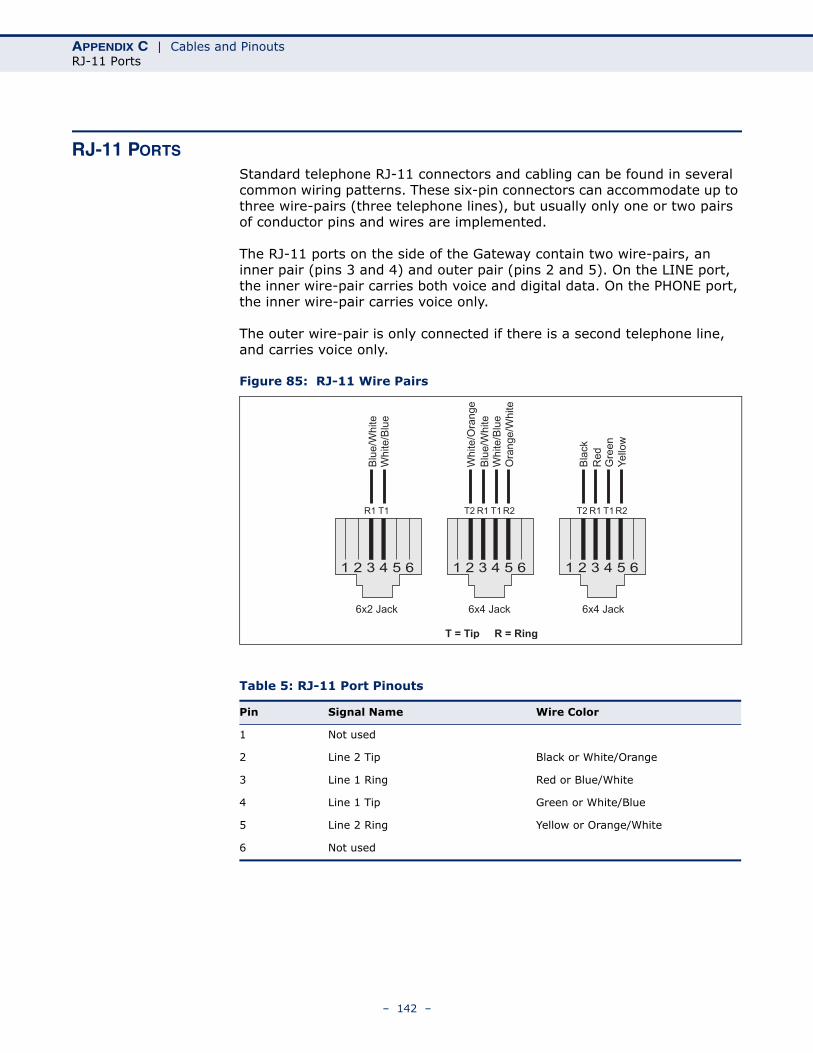
APPENDIX C | Cables and PinoutsRJ-11 Ports
RJ-11 PORTS
Standard telephone RJ-11 connectors and cabling can be found in several common wiring patterns. These six-pin connectors can accommodate up to three wire-pairs (three telephone lines), but usually only one or two pairs of conductor pins and wires are implemented.
The RJ-11 ports on the side of the Gateway contain two wire-pairs, an inner pair (pins 3 and 4) and outer pair (pins 2 and 5). On the LINE port, the inner wire-pair carries both voice and digital data. On the PHONE port, the inner wire-pair carries voice only.
The outer wire-pair is only connected if there is a second telephone line, and carries voice only.
Figure 85: RJ-11 Wire Pairs
Table 5: RJ-11 Port Pinouts
Pin Signal Name Wire Color
1 Not used
2 Line 2 Tip Black or White/Orange
3 Line 1 Ring Red or Blue/White
4 Line 1 Tip Green or White/Blue
5 Line 2 Ring Yellow or Orange/White
6 Not used
1 2 3 4 5 6
Blu
e/W
hite
Wh
ite
/Blu
e
R1 T1
1 2 3 4 5 6
Re
dG
ree
n
R1 T1 R2T2
Bla
ck
Ye
llow
1 2 3 4 5 6
Blu
e/W
hite
Wh
ite
/Blu
e
R1 T1 R2T2
Wh
ite
/Ora
ng
e
Ora
ng
e/W
hite
6x2 Jack 6x4 Jack6x4 Jack
T = Tip R = Ring
– 142 –
GLOSSARY
10BASE-T IEEE 802.3-2005 specification for 10 Mbps Ethernet over two pairs of Category 3 or better UTP cable.
100BASE-TX IEEE 802.3-2005 specification for 100 Mbps Fast Ethernet over two pairs of Category 5 or better UTP cable.
1000BASE-T IEEE 802.3ab specification for 1000 Mbps Gigabit Ethernet over four pairs of Category 5 or better UTP cable.
ACCESS POINT An internetworking device that seamlessly connects wired and wireless networks. Access points attached to a wired network, support the creation of multiple radio cells that enable roaming throughout a facility.
ADVANCED ENCRYPTIONSTANDARD (AES)
An encryption algorithm that implements symmetric key cryptography. AES provides very strong encryption using a completely different ciphering algorithm to TKIP and WEP.
AUTHENTICATION The process to verify the identity of a client requesting network access. IEEE 802.11 specifies two forms of authentication: open system and shared key.
BACKBONE The core infrastructure of a network. The portion of the network that transports information from one central location to another central location where it is unloaded onto a local system.
BEACON A signal periodically transmitted from the access point that is used to identify the service set, and to maintain contact with wireless clients.
BROADCAST KEY Broadcast keys are sent to stations using dynamic keying. Dynamic broadcast key rotation is often used to allow the access point to generate a random group key and periodically update all key-management capable wireless clients.
– 143 –
GLOSSARY
DYNAMIC HOSTCONFIGURATION
PROTOCOL (DHCP)
Provides a framework for passing configuration information to hosts on a TCP/IP network. DHCP is based on the Bootstrap Protocol (BOOTP), adding the capability of automatic allocation of reusable network addresses and additional configuration options.
ENCRYPTION Data passing between the access point and clients can use encryption to protect from interception and evesdropping.
ETHERNET A popular local area data communications network, which accepts transmission from computers and terminals.
FILE TRANSFERPROTOCOL (FTP)
A TCP/IP protocol used for file transfer.
HYPERTEXT TRANSFERPROTOCOL (HTTP)
HTTP is a standard used to transmit and receive all data over the World Wide Web.
IEEE 802.11A A wireless standard that supports high-speed communications in the 5 GHz band using Orthogonal Frequency Division Multiplexing (OFDM). The standard supports data rates of 6, 12, 24, and 54 Mbps.
IEEE 802.11B A wireless standard that supports wireless communications in the 2.4 GHz band using Direct Sequence Spread Spectrum (DSSS). The standard provides for data rates of 1, 2, 5.5, and 11 Mbps.
IEEE 802.11G A wireless standard that supports wireless communications in the 2.4 GHz band using Orthogonal Frequency Division Multiplexing (OFDM). The standard provides for data rates of 6, 9, 12, 18, 24, 36, 48, 54 Mbps. IEEE 802.11g is also backward compatible with IEEE 802.11b.
INFRASTRUCTURE An integrated wireless and wired LAN is called an infrastructure configuration.
LOCAL AREA NETWORK(LAN)
A group of interconnected computer and support devices.
MAC ADDRESS The physical layer address used to uniquely identify network nodes.
– 144 –
GLOSSARY
NETWORK TIMEPROTOCOL (NTP)
NTP provides the mechanisms to synchronize time across the network. The time servers operate in a hierarchical-master-slave configuration in order to synchronize local clocks within the subnet and to national time standards via wire or radio.
OPEN SYSTEM A security option which broadcasts a beacon signal including the access point’s configured SSID. Wireless clients can read the SSID from the beacon, and automatically reset their SSID to allow immediate connection to the nearest access point.
ORTHOGONALFREQUENCY DIVISION
MULTIPLEXING (ODFM)
OFDM allows multiple users to transmit in an allocated band by dividing the bandwidth into many narrow bandwidth carriers.
SERVICE SET IDENTIFIER(SSID)
An identifier that is attached to packets sent over the wireless LAN and functions as a password for joining a particular radio cell; i.e., Basic Service Set (BSS).
SESSION KEY Session keys are unique to each client, and are used to authenticate a client connection, and correlate traffic passing between a specific client and the access point.
SHARED KEY A shared key can be used to authenticate each client attached to a wireless network. Shared Key authentication must be used along with the 802.11 Wireless Equivalent Privacy algorithm.
SIMPLE NETWORK TIMEPROTOCOL (SNTP)
SNTP allows a device to set its internal clock based on periodic updates from a Network Time Protocol (NTP) server. Updates can be requested from a specific NTP server, or can be received via broadcasts sent by NTP servers.
TEMPORAL KEYINTEGRITY PROTOCOL
(TKIP)
A data encryption method designed as a replacement for WEP. TKIP avoids the problems of WEP static keys by dynamically changing data encryption keys.
TRIVIAL FILE TRANSFERPROTOCOL (TFTP)
A TCP/IP protocol commonly used for software downloads.
VIRTUAL ACCESS POINT(VAP)
Virtual AP technology multiplies the number of Access Points present within the RF footprint of a single physical access device. With Virtual AP technology, WLAN users within the device.s footprint can associate with what appears to be different access points and their associated network
– 145 –
GLOSSARY
services. All the services are delivered using a single radio channel, enabling Virtual AP technology to optimize the use of limited WLAN radio spectrum.
WI-FI PROTECTEDACCESS
WPA employs 802.1X as its basic framework for user authentication and dynamic key management to provide an enhanced security solution for 802.11 wireless networks.
WIRED EQUIVALENTPRIVACY (WEP)
WEP is based on the use of security keys and the popular RC4 encryption algorithm. Wireless devices without a valid WEP key will be excluded from network traffic.
WPA PRE-SHARED KEY(WPA-PSK)
WPA-PSK can be used for small office networks with a limited number of users that may not need a high level of security. WPA-PSK provides a simple security implementation that uses just a pre-shared password for network access.
– 146 –

INDEX
Aaccess control 82ACLs 108ADSL capability 66ADSL modulation 65ADSL settings 65ADSL tone 67ADSL tone diagnostics 129advanced settings 85AnnexL option 66AnnexM option 66antenna 26Applications 22ARP table 55ATM loopback 128ATM settings 63auto PVC settings 63
Bbackup/restore settings 103bridge configuration 121bridging table 56
Cchannel configuration 59commit/reboot 101connect Ethernet cable 32connecting and powering on 32current ATM VC table 60, 64
DDDNS 113denial of service (DoS) 98DHCP settings 70
DHCP relay 71DHCP server 72no DHCP 70
DMZ 96DNS server 112domain blocking 95DSL statistics 53
EEthernet port 28
Hhardware capabilities 21hardware description 24
IIGMP proxy configuration 120initial configuration 35installing the access point 29introduction 21IP pass through 122IP QoS 118IP/Port filtering 88ISP settings 35
Kkey features 21
LLAN interface 69LAN status 50LAN/WAN diagnostics test 130LED indicators 27location selection 29login page 35
MMAC filtering 90mounting on a horizontal surface 30mounting on a wall 31
Ppackage contents 23password setup 106ping 127port forwarding 92position antennas 33power connector 28
Rremote access 102reset button 28RIP configuration 117routing configuration 115
– 147 –
INDEX
routing table 57
Ssecond BSSID 77self test 32SNMP protocol configuration 123subnet mask 40system log 104system requirements 29system status 48
Ttime zone 109TR-069 configuration 124traffic statistics 52
Uupgrade firmware 107UPnP 110URL blocking 94
WWAN status 49WDS 83wireless security setup 78
common wireless parameters 78WEP security 79
WLAN basic settings 76WLAN status 51WPA security 81
– 148 –

INDEX
– 149 –

149100000005A R01
SMC7901WBRA2 B1