Embed Size (px)
Citation preview
2
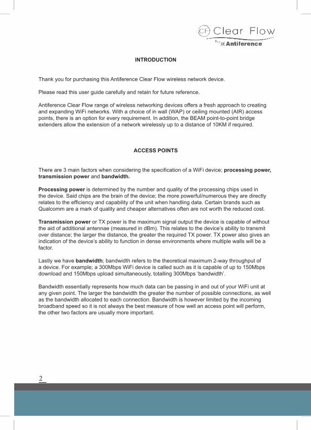
INTRODUCTION
Thank you for purchasing this Antiference Clear Flow wireless network device.
Please read this user guide carefully and retain for future reference.
Antiference Clear Flow range of wireless networking devices offers a fresh approach to creating and expanding WiFi networks. With a choice of in wall (WAP) or ceiling mounted (AIR) access points, there is an option for every requirement. In addition, the BEAM point-to-point bridge extenders allow the extension of a network wirelessly up to a distance of 10KM if required.
ACCESS POINTS
There are 3 main factors when considering the specification of a WiFi device; processing power, transmission power and bandwidth.
Processing power is determined by the number and quality of the processing chips used in the device. Said chips are the brain of the device; the more powerful/numerous they are directly relates to the efficiency and capability of the unit when handling data. Certain brands such as Qualcomm are a mark of quality and cheaper alternatives often are not worth the reduced cost.
Transmission power or TX power is the maximum signal output the device is capable of without the aid of additional antennae (measured in dBm). This relates to the device’s ability to transmit over distance; the larger the distance, the greater the required TX power. TX power also gives an indication of the device’s ability to function in dense environments where multiple walls will be a factor. Lastly we have bandwidth; bandwidth refers to the theoretical maximum 2-way throughput of a device. For example; a 300Mbps WiFi device is called such as it is capable of up to 150Mbps download and 150Mbps upload simultaneously, totalling 300Mbps ‘bandwidth’.
Bandwidth essentially represents how much data can be passing in and out of your WiFi unit at any given point. The larger the bandwidth the greater the number of possible connections, as well as the bandwidth allocated to each connection. Bandwidth is however limited by the incoming broadband speed so it is not always the best measure of how well an access point will perform, the other two factors are usually more important.
3
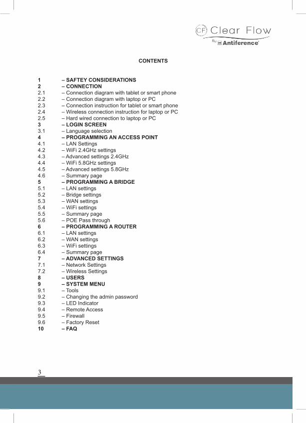
CONTENTS
1 – SAFTEY CONSIDERATIONS2 – CONNECTION 2.1 – Connection diagram with tablet or smart phone2.2 – Connection diagram with laptop or PC2.3 – Connection instruction for tablet or smart phone2.4 – Wireless connection instruction for laptop or PC2.5 – Hard wired connection to laptop or PC3 – LOGIN SCREEN3.1 – Language selection4 – PROGRAMMING AN ACCESS POINT4.1 – LAN Settings4.2 – WiFi 2.4GHz settings4.3 – Advanced settings 2.4GHz4.4 – WiFi 5.8GHz settings4.5 – Advanced settings 5.8GHz4.6 – Summary page5 – PROGRAMMING A BRIDGE5.1 – LAN settings5.2 – Bridge settings5.3 – WAN settings5.4 – WiFi settings5.5 – Summary page5.6 – POE Pass through6 – PROGRAMMING A ROUTER6.1 – LAN settings6.2 – WAN settings6.3 – WiFi settings6.4 – Summary page7 – ADVANCED SETTINGS7.1 – Network Settings7.2 – Wireless Settings8 – USERS9 – SYSTEM MENU9.1 – Tools9.2 – Changing the admin password9.3 – LED Indicator9.4 – Remote Access9.5 – Firewall9.6 – Factory Reset10 – FAQ
4
1 SAFETY CONSIDERATIONS
1.1 Connecting the power supply
This device must be connected to a 48V supply either from a Clear Flow power injector or a POE Ethernet switch. Please check the voltage and current rating to ensure correct supply is used as failure to do so may damage the product and will not be covered under warranty.
1.2 Liquids
DO NOT place liquids on or near the devices at any time as this may damage the product. Outdoor devices must be mounted in the correct orientation to prevent water ingress.
1.3 Cleaning
Only use a damp cloth for cleaning. We do not recommend using solvent based products as this may damage the case.
1.4 Repairs
No attempt should be made to carry out repairs on these devices unless trained or qualified to do
so. Opening the device may invalidate the warranty.
5
BEFORE YOU START
DO NOT connect the AP/bridge to the network until programming is complete.
Set up of all Clear Flow devices can be achieved with a tablet, smart phone or laptop.
Using the on-board GUI, the device can be set up via the wizard as an AP, Bridge or Router.
2 CONNECTION
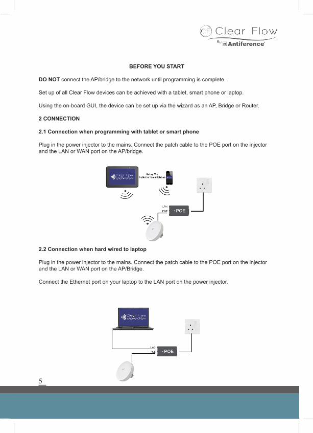
2.1 Connection when programming with tablet or smart phone
Plug in the power injector to the mains. Connect the patch cable to the POE port on the injector and the LAN or WAN port on the AP/bridge.
2.2 Connection when hard wired to laptop
Plug in the power injector to the mains. Connect the patch cable to the POE port on the injector and the LAN or WAN port on the AP/Bridge.
Connect the Ethernet port on your laptop to the LAN port on the power injector.
6
2.3 Connection using a tablet or smart phone
The Clear Flow Wireless range can be easily programmed using a smart phone or tablet using the following procedure:
Power up the AP/Bridge and wait for the device to boot-up. This may take a few minutes.
Using your smart device, scan for wireless networks. When you find the AIR, BEAM or WAP Wifi network, click connect.
Open a browser on your smart device and login to the AP/bridge using the default IP address 192.168.1.200.
To continue programming with a smart phone or tablet, please go to section 3
2.4 Wireless connection to your access point with a laptop
It is possible to program the access points via a laptop or PC. Simply search for the AP in your wireless network connections. Once connected open a web browser and type the default IP address 192.168.1.200 to reach the login screen.
*Please note: Some older WiFi devices may not be capable of connecting to a 5.8GHz Wi-Fi connection. This only applies when configuring the BEAM 5 or BEAM PRO via WiFi as these devices will be invisible to a non Dual band laptop/mobile phone. In which case please see section 2.5.
Go to section 3
2.5 Hard wired connection to your access point with a laptop
Connect an Ethernet cable from the LAN port of your AP to your laptop then type ‘192.168.1.200’ into your web browser. If the Clear Flow home page loads then please go to section 3.
If not then it is likely that your laptop is on a different IP range.
When programming via Ethernet, it is only possible when the PC is set onto the same IP range as the AP/Bridge.
In the average Class C network an IP address is made up of 4 groups of numbers. In order for devices to communicate on a network, the first 3 groups of numbers must match and the last group must be unique to the individual device.
For example: The IP addresses 192.168.1.100 and 192.168.1.200 can communicate. The IP addresses 192.168.1.100 and 192.168.0.200 cannot communicate.
7
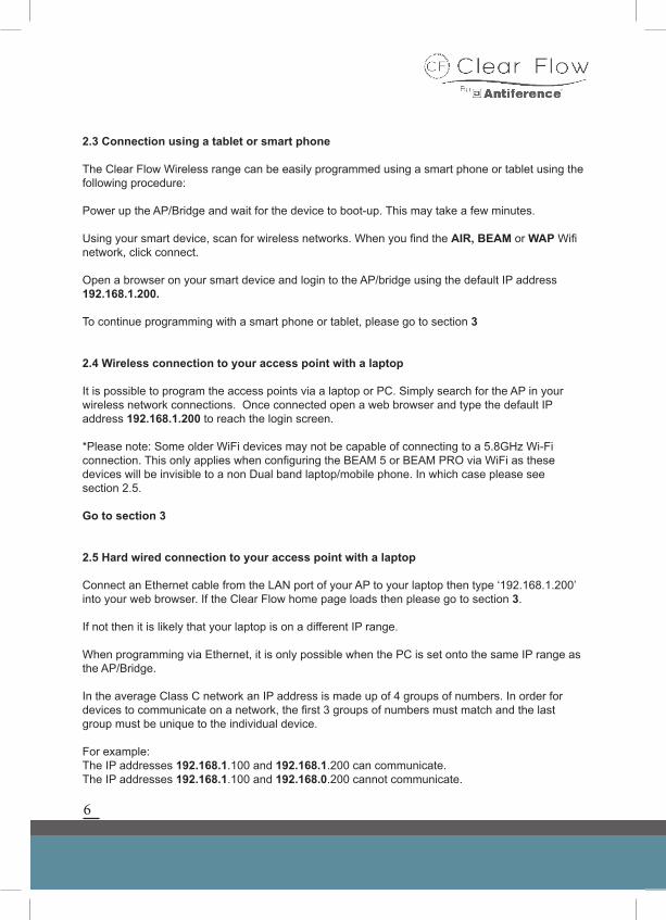
If you need to change the IP address, navigate to the Network & Sharing Centre in the Control Panel or via the shortcut link on the task bar (if present).
Once in the Network & Sharing Centre, click ‘change adaptor settings’
Then double click ‘local area connection’
Click ‘properties’
8
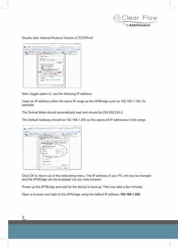
Double click ‘Internet Protocol Version 4 (TCP/IPv4)’
Next, toggle option to ‘use the following IP address.
Insert an IP address within the same IP range as the AP/Bridge such as 192.168.1.100, for example
The Subnet Mask should automatically load and should be 255.255.255.0.
The Default Gateway should be 192.168.1.255 as this opens all IP addresses in this range.
Click OK to return out of the networking menu. The IP address of your PC will now be changed and the AP/Bridge can be accessed via your web browser.
Power up the AP/Bridge and wait for the device to boot-up. This may take a few minutes.
Open a browser and login to the AP/bridge using the default IP address 192.168.1.200.
9
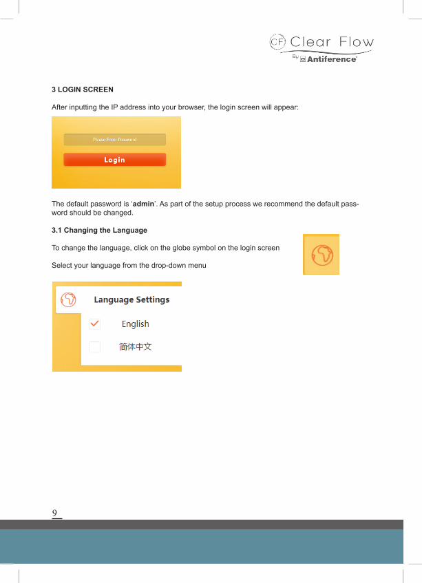
3 LOGIN SCREEN
After inputting the IP address into your browser, the login screen will appear:
The default password is ‘admin’. As part of the setup process we recommend the default pass-word should be changed.
3.1 Changing the Language
To change the language, click on the globe symbol on the login screen
Select your language from the drop-down menu
10
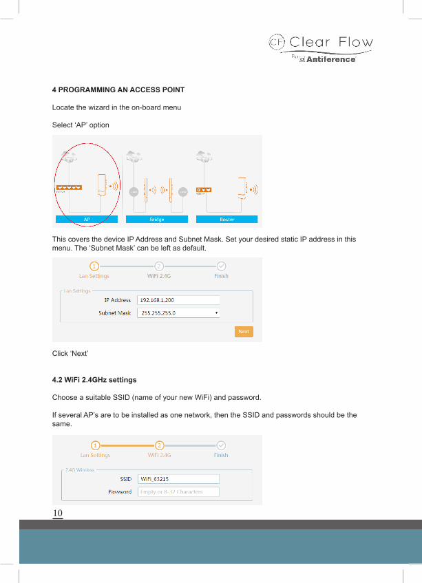
4 PROGRAMMING AN ACCESS POINT
Locate the wizard in the on-board menu
Select ‘AP’ option
4.1 LAN settings
This covers the device IP Address and Subnet Mask. Set your desired static IP address in this menu. The ‘Subnet Mask’ can be left as default.
Click ‘Next’
4.2 WiFi 2.4GHz settings
Choose a suitable SSID (name of your new WiFi) and password.
If several AP’s are to be installed as one network, then the SSID and passwords should be the same.
11
4.3 Advanced Settings 2.4GHz
Bandwidth selection – this should be set to 20MHz for 2.4GHz WiFi systems.
Select the country
Channel selection – choose a specific channel or run in auto mode.
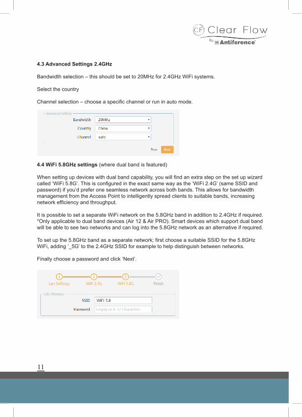
4.4 WiFi 5.8GHz settings (where dual band is featured)
When setting up devices with dual band capability, you will find an extra step on the set up wizard called ‘WiFi 5.8G’. This is configured in the exact same way as the ‘WiFi 2.4G’ (same SSID and password) if you’d prefer one seamless network across both bands. This allows for bandwidth management from the Access Point to intelligently spread clients to suitable bands, increasing network efficiency and throughput.
It is possible to set a separate WiFi network on the 5.8GHz band in addition to 2.4GHz if required. *Only applicable to dual band devices (Air 12 & Air PRO). Smart devices which support dual band will be able to see two networks and can log into the 5.8GHz network as an alternative if required.
To set up the 5.8GHz band as a separate network; first choose a suitable SSID for the 5.8GHz WiFi, adding ‘_5G’ to the 2.4GHz SSID for example to help distinguish between networks.
Finally choose a password and click ‘Next’.
12
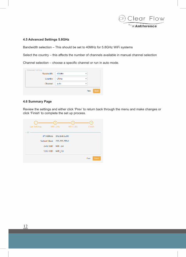
4.5 Advanced Settings 5.8GHz
Bandwidth selection – This should be set to 40MHz for 5.8GHz WiFi systems
Select the country – this affects the number of channels available in manual channel selection
Channel selection – choose a specific channel or run in auto mode.
4.6 Summary Page
Review the settings and either click ‘Prev’ to return back through the menu and make changes or click ‘Finish’ to complete the set up process.
13
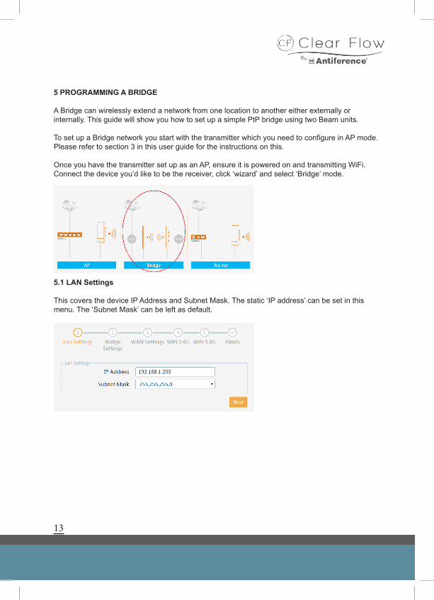
5 PROGRAMMING A BRIDGE
A Bridge can wirelessly extend a network from one location to another either externally or internally. This guide will show you how to set up a simple PtP bridge using two Beam units.
To set up a Bridge network you start with the transmitter which you need to configure in AP mode. Please refer to section 3 in this user guide for the instructions on this.
Once you have the transmitter set up as an AP, ensure it is powered on and transmitting WiFi. Connect the device you’d like to be the receiver, click ‘wizard’ and select ‘Bridge’ mode.
5.1 LAN Settings
This covers the device IP Address and Subnet Mask. The static ‘IP address’ can be set in this menu. The ‘Subnet Mask’ can be left as default.
14
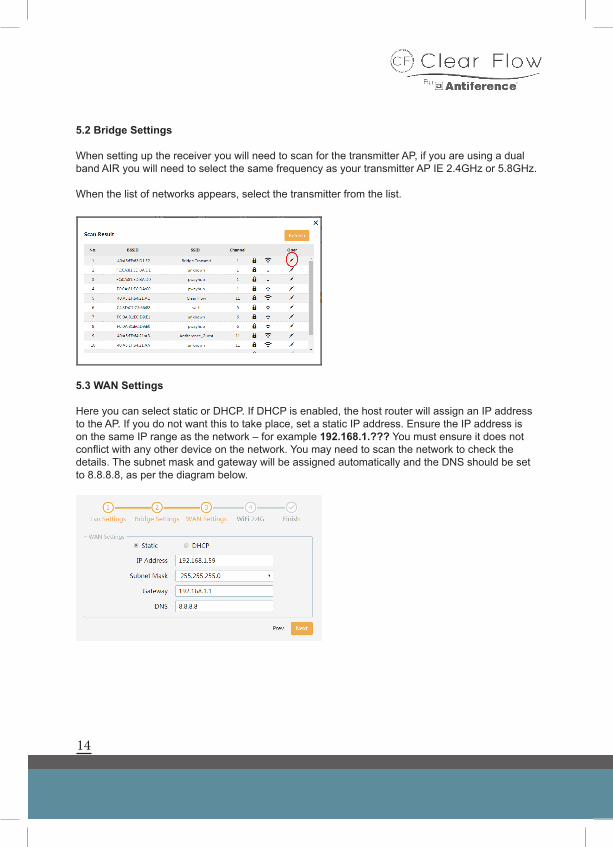
5.2 Bridge Settings
When setting up the receiver you will need to scan for the transmitter AP, if you are using a dual band AIR you will need to select the same frequency as your transmitter AP IE 2.4GHz or 5.8GHz.
When the list of networks appears, select the transmitter from the list.
5.3 WAN Settings
Here you can select static or DHCP. If DHCP is enabled, the host router will assign an IP address to the AP. If you do not want this to take place, set a static IP address. Ensure the IP address is on the same IP range as the network – for example 192.168.1.??? You must ensure it does not conflict with any other device on the network. You may need to scan the network to check the details. The subnet mask and gateway will be assigned automatically and the DNS should be set to 8.8.8.8, as per the diagram below.
15
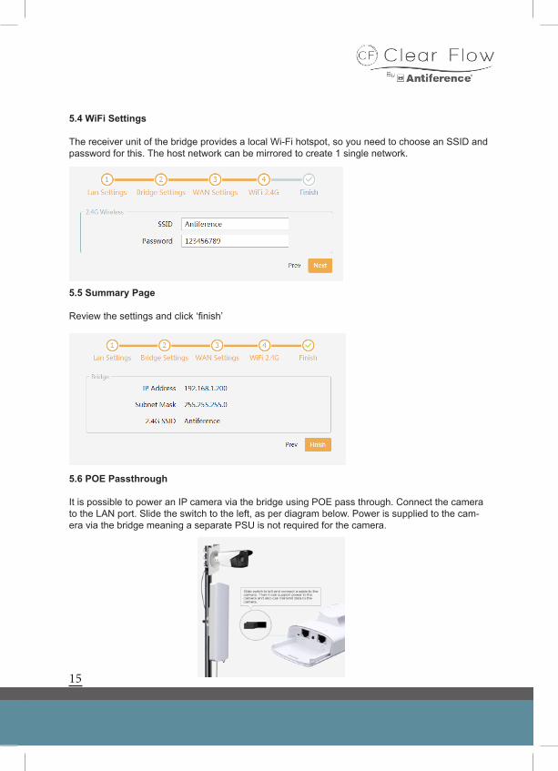
5.4 WiFi Settings
The receiver unit of the bridge provides a local Wi-Fi hotspot, so you need to choose an SSID and password for this. The host network can be mirrored to create 1 single network.
5.5 Summary Page
Review the settings and click ‘finish’
5.6 POE Passthrough
It is possible to power an IP camera via the bridge using POE pass through. Connect the camera to the LAN port. Slide the switch to the left, as per diagram below. Power is supplied to the cam-era via the bridge meaning a separate PSU is not required for the camera.
16
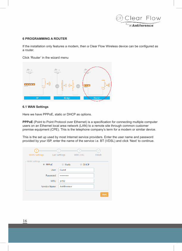
6 PROGRAMMING A ROUTER
If the installation only features a modem, then a Clear Flow Wireless device can be configured as a router.
Click ‘Router’ in the wizard menu
6.1 WAN Settings
Here we have PPPoE, static or DHCP as options.
PPPoE (Point to Point Protocol over Ethernet) is a specification for connecting multiple computer users on an Ethernet local area network (LAN) to a remote site through common customer premise equipment (CPE). This is the telephone company’s term for a modem or similar device.
This is the set up used by most Internet service providers. Enter the user name and password provided by your ISP, enter the name of the service i.e. BT (VDSL) and click ‘Next’ to continue.
17
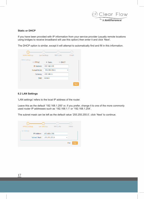
Static or DHCP
If you have been provided with IP information from your service provider (usually remote locations using bridges to receive broadband will use this option) then enter it and click ‘Next’.
The DHCP option is similar, except it will attempt to automatically find and fill in this information.
6.2 LAN Settings
‘LAN settings’ refers to the local IP address of the router.
Leave this as the default ‘192.168.1.200’ or, if you prefer, change it to one of the more commonly used router IP addresses such as ‘192.168.1.1’ or ‘192.168.1.254’.
The subnet mask can be left as the default value ‘255.255.255.0’, click ‘Next’ to continue.
18
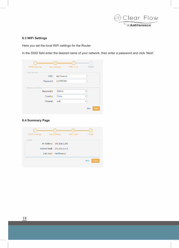
6.3 WiFi Settings
Here you set the local WiFi settings for the Router.
In the SSID field enter the desired name of your network, then enter a password and click ‘Next’.
6.4 Summary Page
19
7 ADVANCED SETTINGS
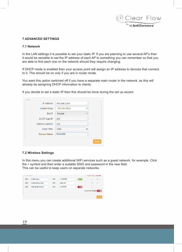
7.1 Network
In the LAN settings it is possible to set your static IP. If you are planning to use several AP’s then it would be sensible to set the IP address of each AP to something you can remember so that you are able to find each one on the network should they require changing.
If DHCP mode is enabled then your access point will assign an IP address to devices that connect to it. This should be on only if you are in router mode.
You want this option switched off if you have a separate main router in the network, as this will already be assigning DHCP information to clients.
If you decide to set a static IP then this should be done during the set up wizard.
7.2 Wireless Settings
In this menu you can create additional WiFi services such as a guest network, for example. Click the + symbol and then enter a suitable SSID and password in the new field. This can be useful to keep users on separate networks.
20
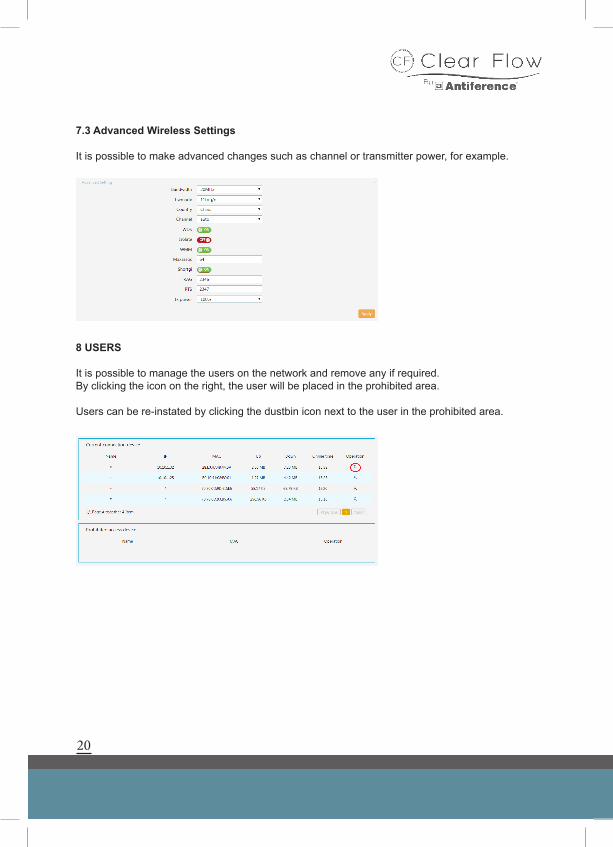
7.3 Advanced Wireless Settings
It is possible to make advanced changes such as channel or transmitter power, for example.
8 USERS
It is possible to manage the users on the network and remove any if required. By clicking the icon on the right, the user will be placed in the prohibited area.
Users can be re-instated by clicking the dustbin icon next to the user in the prohibited area.
21
9 SYSTEM MENU
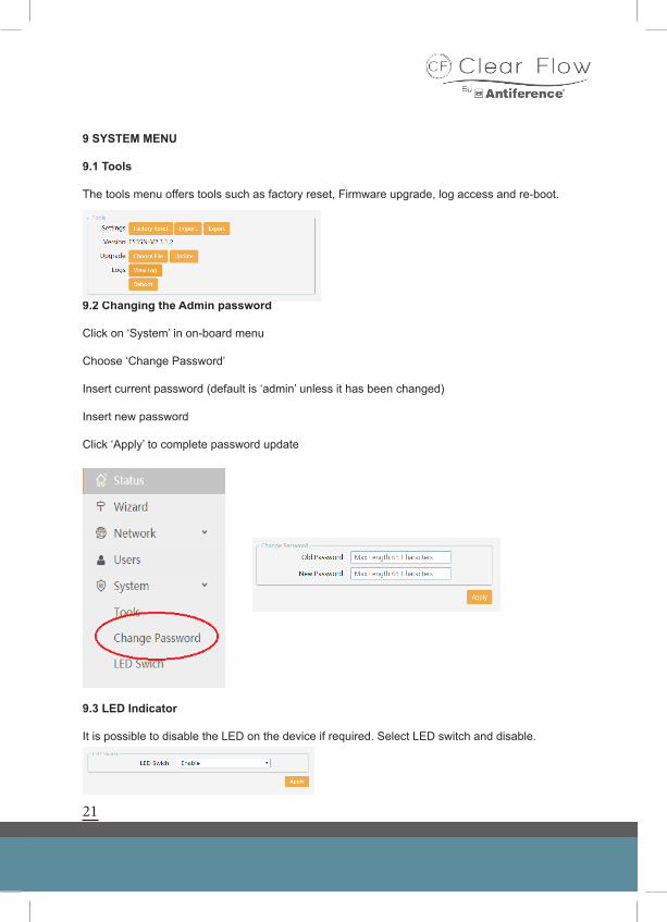
9.1 Tools
The tools menu offers tools such as factory reset, Firmware upgrade, log access and re-boot.
9.2 Changing the Admin password
Click on ‘System’ in on-board menu
Choose ‘Change Password’
Insert current password (default is ‘admin’ unless it has been changed)
Insert new password
Click ‘Apply’ to complete password update
9.3 LED Indicator
It is possible to disable the LED on the device if required. Select LED switch and disable.
22
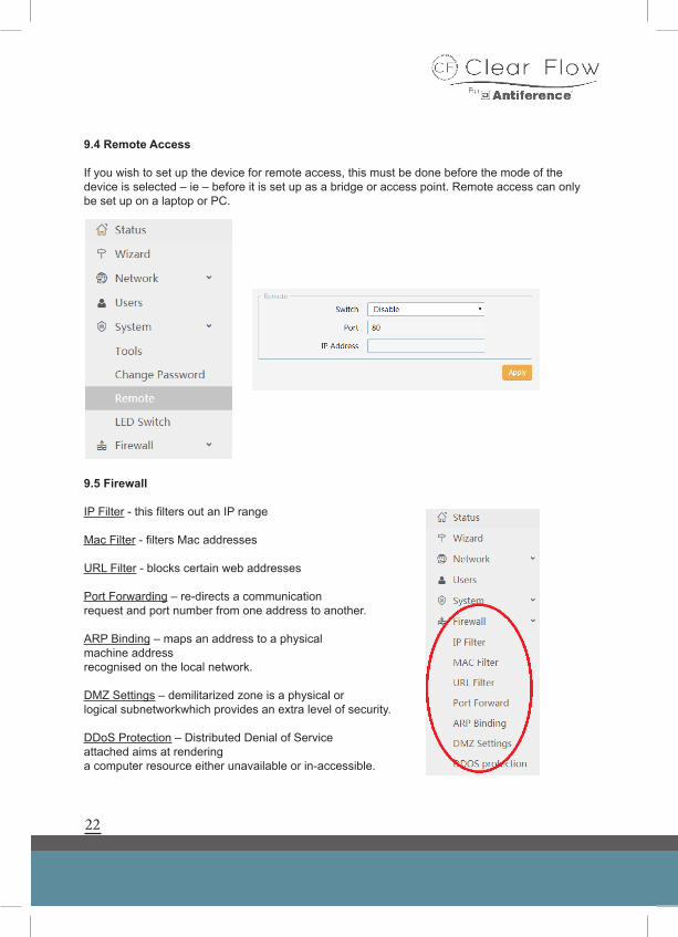
9.4 Remote Access
If you wish to set up the device for remote access, this must be done before the mode of the device is selected – ie – before it is set up as a bridge or access point. Remote access can only be set up on a laptop or PC.
9.5 Firewall
IP Filter - this filters out an IP range
Mac Filter - filters Mac addresses
URL Filter - blocks certain web addresses
Port Forwarding – re-directs a communication request and port number from one address to another.
ARP Binding – maps an address to a physical machine address recognised on the local network.
DMZ Settings – demilitarized zone is a physical or logical subnetworkwhich provides an extra level of security.
DDoS Protection – Distributed Denial of Service attached aims at renderinga computer resource either unavailable or in-accessible.
23
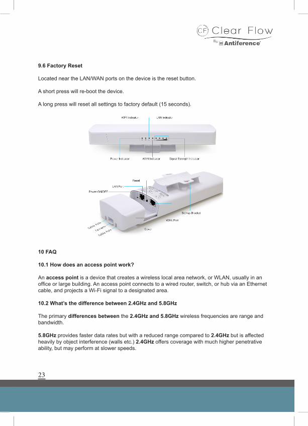
9.6 Factory Reset
Located near the LAN/WAN ports on the device is the reset button.
A short press will re-boot the device.
A long press will reset all settings to factory default (15 seconds).
10 FAQ
10.1 How does an access point work?
An access point is a device that creates a wireless local area network, or WLAN, usually in an office or large building. An access point connects to a wired router, switch, or hub via an Ethernet cable, and projects a Wi-Fi signal to a designated area.
10.2 What’s the difference between 2.4GHz and 5.8GHz
The primary differences between the 2.4GHz and 5.8GHz wireless frequencies are range and bandwidth.
5.8GHz provides faster data rates but with a reduced range compared to 2.4GHz but is affected heavily by object interference (walls etc.) 2.4GHz offers coverage with much higher penetrative ability, but may perform at slower speeds.
24
10.3 What is an IP Address?
An Internet Protocol Address (IP address) is a numerical label assigned to each device connected to a computer network that uses the Internet Protocol for communication. An IP address serves two principal functions: host or network interface identification and location addressing.
10.4 How do I find my devices IP address?
A scan of the network will identify the IP address of your device and an app such as FING (available on iOS & Android) is useful for this task.
10.5 What Wi-Fi channel is my device using?
If using auto mode, the device will select a channel in the band automatically and if other wireless devices are being used such as a baby monitor or wireless phone, it is useful to know what other channels are being used in the building in order to avoid them.
A Wi-Fi analyser should be used for this to ascertain the actual air radio noise. SSID’s can be discussed at length but an analyser which shows the energy in the air would be recommended such as Wi-Fi Analyser (Android only).
10.6 What do the LED’s indicate on the AIR access point?
Blue – Wireless/Wi-Fi
Red – WAN
Green – LAN
The LED can be disabled in the system menu.
Declaration of Conformity
We, ANTIFERENCE LIMITED herewith declare that the CLEAR FLOW Wireless access point products comply with all essential requirements and other applicable conditions set forth on directive 1999/05/CE.
According to the WEEE (Waste Electrical and Electrical Equipment) EU Directive, do not dispose of this product as household waste or commercial waste. Waste Electronic Equipment should be appropriately collected and recycled as required by practices established for your country. For information on recycling of this product, please contact your local authorities, your household waste disposal service or the shop where you purchased the product
25
Product Range
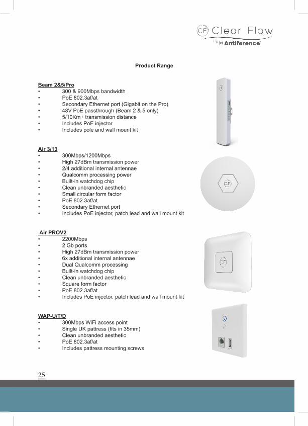
Beam 2&5/Pro• 300 & 900Mbps bandwidth• PoE 802.3af/at• Secondary Ethernet port (Gigabit on the Pro)• 48V PoE passthrough (Beam 2 & 5 only)• 5/10Km+ transmission distance• Includes PoE injector• Includes pole and wall mount kit
Air 3/13• 300Mbps/1200Mbps• High 27dBm transmission power• 2/4 additional internal antennae• Qualcomm processing power• Built-in watchdog chip• Clean unbranded aesthetic• Small circular form factor• PoE 802.3af/at• Secondary Ethernet port• Includes PoE injector, patch lead and wall mount kit
Air PROV2• 2200Mbps • 2 Gb ports• High 27dBm transmission power• 6x additional internal antennae• Dual Qualcomm processing• Built-in watchdog chip• Clean unbranded aesthetic• Square form factor• PoE 802.3af/at• Includes PoE injector, patch lead and wall mount kit
WAP-U/T/D• 300Mbps WiFi access point• Single UK pattress (fits in 35mm)• Clean unbranded aesthetic• PoE 802.3af/at• Includes pattress mounting screws