Embed Size (px)
Citation preview

user guide &
fitting instructions

fitting INSTRUCTIONS version 1-22
© 2015 - 2022 2
Thank you for purchasing FREEWheel!
FREEWheel, the most advanced wireless
steering wheel system in the world.
Here’s all the information you’ll need.
CONTENTS YOU WILL NEED
Relay Receiver and Transmitter IP67-rated OFF / [ON] momentary switches
Battery (3V CR2 lithium) and USB cable USB configuration software from www.blinkstop.co.uk
Optionally: 0.7m loom Wire strippers, soldering iron (not Easyfit)
Optionally: Easyfit Transmitter assembly or
button plate bundle comprising IP67-rated
OFF / [ON] momentary switches, nut covers,
button plate, spacer disc, decals
Optionally: hook-and-loop or servo tape, heat shrink
WARNINGS
Please check the contents and read the fitting instructions carefully before commencing
FREEWheel is rated for a maximum load of 15A per channel and MUST be used with additional relays for
higher current loads (additional relays not supplied).
FEATURES
• Wireless solution allows full push-button and paddle control with a detachable steering wheel
• Integrated BlinkSTOP and BeamSTOP functions – smart indicator cancelling and headlight control
• Integrated IVA fog mode – inhibits and resets fog lights when headlights are turned off
• Supports two simultaneous button presses – includes indicator channel hazard modes
• Uniquely, lets you use your choice of buttons, paddles and mounts. No more being tied to a
manufacturer's styling choices!
• Supports low or high-side switching of up to 15A at 12VDC using internal relays
• Choice of momentary and latching switch behaviour for all channels via USB configuration software

fitting INSTRUCTIONS version 1-22
© 2015 - 2022 3
TRANSMITTER INSTALLATION
SPECIFICATION
Compact case in flame-retardant ABS plastic. Requires
one 3V CR2 lithium battery. Weight with battery: 61g
Robust performance even at 2.65V. Unique Transmitter
ID prevents cross-talk from nearby kits.
No need to disconnect the Transmitter battery if the
vehicle is off the road. The sleep drain of 0.9uA and
25mA drain per ~20msec button press allows over 6
million transmissions.
Tri-colour LED indicating performance state:
• GREEN = Transmit OK. Transmission successfully
received and acknowledged by the Receiver;
• ORANGE = Transmit Fail. Transmission not
acknowledged by the Receiver. Possible causes
are obstruction, lack of range or de-powered
Receiver (e.g., vehicle ignition is off);
• RED = Low Battery <2.65V. Replace battery now.
Transmission time of 6 milliseconds for a real-time response.

fitting INSTRUCTIONS version 1-22
© 2015 - 2022 4
EASYFIT TRANSMITTER INSTALLATION INSTRUCTIONS
Easyfit Transmitter is supplied preassembled and configured to your specification.
The Easyfit Transmitter button plate is pre-drilled to support standard 50 to 50.8mm and 70mm PCD steering
wheel bosses. The rear plate is additionally pre-drilled to suit 74mm PCD and can be used as a guide to
gently drill through the button plate and/or spacer disk, if required. Use a 6mm HSS drill bit with light
pressure and low speed, with the parts securely clamped.
8-Channel Easyfit Transmitter shown

fitting INSTRUCTIONS version 1-22
© 2015 - 2022 5
PIGTAILED TRANSMITTER INSTALLATION INSTRUCTIONS
Use of good quality, IP67 rated OFF / [ON] momentary
switches is recommended, such as Multicomp’s
MCPAS6B2M1CE7, available from Farnell. Illuminated
switches are not supported.
1. Wiring
DO NOT solder the switches while the Transmitter battery is
fitted, as damage may occur.
The switches are all made to a common ground, so you
can connect the ground wires as you wish.
If used, Left / Right Indicators, Main Beam and Fog MUST
be connected to the wires shown because this is
matched by the relay control software. See Figure 1
through Figure 4 for suggested indicator and main beam
wiring diagrams.
When stripping the outer insulation, please take care not
to damage the wires inside. Leave sufficient wire for
future soldering of unused channels, and cover with heat-
shrink.
2. Nut Covers (if supplied)
Fit the nut covers to the rear of the switches. It is deliberately a tight, push fit. The covers can be secured
in place with a little hot melt glue once all testing is complete.
3. Attach the Transmitter to the Steering Wheel
The Transmitter can be easily attached to the reverse of the wheel or button plate using hook-and-loop
pads or servo tape.
4. Battery Fitting and Removal
Fit the CR2 battery to the Transmitter. When fitting the battery, take particular care in removing the case
lid and inserting the battery correctly, noting that the ‘+’ end of the battery is nearest to the LED.
To remove the battery, carefully prise out the battery – it is deliberately a tight fit in the holder.
5. IMPORTANT - Transmitter Testing
Follow the Receiver configuration software instructions to connect the Receiver to your Windows
PC/laptop and to verify that your button presses for each channel are being sent by the Transmitter.
Wire Colour Function
BLACK Ground YELLOW Ground WHITE Ground
ORANGE Ground RED Ch1 or L Indicator
GREEN Ch2 or R Indicator BLUE Ch3 or Main Beam
BROWN Ch4 or Fog GREY Ch5 PINK Ch6
CYAN Ch7 PURPLE Ch8
Transmitter wiring key

fitting INSTRUCTIONS version 1-22
© 2015 - 2022 6
RECEIVER CONFIGURATION SOFTWARE
INSTALLATION AND USAGE INSTRUCTIONS
NOTE: DO NOT disconnect the USB power during
programming or the chip memory may corrupt!
1. Software Installation
Connect the Receiver USB cable to the Windows PC.
Windows 7, 8 and 10 are supported. Windows will auto-
detect and install the FTDI Driver.
In the event the PC does not self-install the FTDI driver,
download and install FTDI’s VCP Virtual COM Port driver
from: http://www.ftdichip.com/Drivers/VCP.htm
2. Identify the correct COM port used by FREEWheel
Open Windows Device Manager [Start .. Run .. or
Search .. and enter ‘Device Manager’]. The port will
disappear and reappear as you remove and insert the
Receiver USB lead.
Download, extract to Desktop and run the
FREEWheel.exe program from the FREEWheel product
Downloads tab at: http://www.blinkstop.co.uk/
3. Using the Software
Choose the correct COM port from the available drop list and click ‘Connect’. The existing channel
configuration and virtual relay states will be displayed (physical relays are not powered by USB).
Pressing steering wheel buttons connected to the Transmitter will illuminate the corresponding buttons and
toggle or flash the virtual relay states on the software.
CHANNEL CONFIGURATION
4. Select the Configuration tab to set the channel behaviours
Select the desired smart features by checking or unchecking the Indicator, Main and Fog tick boxes.
Unchecking the tick boxes will allow a free choice of momentary or latching behaviour.
To configure the channels, simply press the software switches and adjust the duration slider and click
‘Program’. When successful, you will see ‘Success’ displayed.
To disconnect the Receiver from the USB software, press ‘Disconnect’ then ‘Close’. Now you can safely
disconnect the USB cable. Proceed with installing the Receiver.

fitting INSTRUCTIONS version 1-22
© 2015 - 2022 7
RELAY RECEIVER
SPECIFICATION
4-CHANNEL RECEIVER:
4-Channel Receiver
8-Channel Receiver
• Weight with 0.7m wiring loom: 300g.
• Wiring loom uses 14-gold pin sealed, genuine TE
connector and 18AWG heat resistant, high
temperature, thin wall wires with tinned copper.
8-CHANNEL RECEIVER:
• Weight with 0.7m wiring loom: 385g.
• Wiring loom uses 23-gold pin sealed, genuine TE
connector and 18AWG heat resistant, high
temperature, thin wall wires with tinned copper.
ALL SYSTEMS:
Internal relays are rated for maximum switching current
15A at 12VDC; supports low- or high-side switching of
loads.
Relays are open circuit by default at ignition ON and are
switched by the Transmitter.
Channels are configured using the FREEWheel USB
software and have behaviour options of:
• ALL: momentary [ON] (Transmitter button
follower)
• ALL: latching [ON] / OFF with each separate
Transmitter button press
• Channels 1 & 2: indicator control
• Channel 3: high and low beam function
• Channel 4: IVA fog function
• Channels 5, 6 & 7: inverted momentary function
(8-Channel Receiver only)

fitting INSTRUCTIONS version 1-22
© 2015 - 2022 8
RELAY RECEIVER INSTALLATION INSTRUCTIONS
Inside the FREEWheel Receiver are the
relays and ‘low current circuits’ that
control the relay coils. The white pair
from the receiver for each channel is
the ‘high current circuit’ pair shown.
The white pair can be used to switch
up to 15A and can be wired in
parallel with the existing dashboard
switches, or the switches can be
removed, if preferred.
In ALL cases, additional relays MUST
be used for current loads above 15A
(not supplied).
4-Channel Relay Receiver wiring key 8-Channel Relay Receiver wiring key

fitting INSTRUCTIONS version 1-22
© 2015 - 2022 9
1. Wiring
Identify an ignition-switched circuit that can be used for the power supply to FREEWheel. The FREEWheel
Receiver draws little current (<500mA typically), so will not increase the circuit load significantly.
Identify a suitable Ground connection, ideally direct to the vehicle chassis. Identify the existing circuits and
schematics. These will be critical to successful installation.
See Figure 1 through Figure 4 for suggested indicator and main beam wiring diagrams. Some vehicles as
standard do not provide high beam flashing unless headlamps are ON (e.g., Westfields), so use the
elements of the diagrams applicable to your vehicle.
Choose a cool location for the Receiver inside the car, with minimal (metal) obstructions between
Receiver and Transmitter. Behind the dashboard is normally an ideal place.
With the vehicle battery disconnected, connect Receiver Power and Ground to the previously identified
wires.
2. Receiver Testing
Re-connect the vehicle battery and check the relays can be heard to click when the steering wheel
Transmitter buttons are pressed.
Check that the Transmitter light is reliably GREEN on button presses. ORANGE means that there is a
probable obstruction to two-way communication. You can test the range of the system using this light for
indication.
Once you have reliable communication between Transmitter and Receiver, connect the Windows PC to
the USB connector and use the FREEWheel software to configure the channels, if you have not already
done so (see Receiver configuration software). The software will show the live state of the relays and
button presses.
Now disconnect the vehicle battery and complete the installation of the desired integrated functions.

fitting INSTRUCTIONS version 1-22
© 2015 - 2022 10
INTEGRATED BlinkSTOP FUNCTION
CHANNELS 1 AND 2 SET TO [INDICATORS]
INSTRUCTIONS FOR OPERATION
An indicator can be toggled ON and OFF with each press of your steering wheel push-button.
Toggling an indicator to ON begins a cancelling timer. Indicating will auto-cancel once the timer has
elapsed (6 to 30 seconds, user-configurable via the Receiver configuration software). Indicator auto-
cancelling is inhibited while the brakes are pressed, and afterwards for a short time so that the indicators
can remain ON in traffic or while waiting to turn.
To change indicator, push the opposite button once. The current indicator will cancel, and the opposite
indicator will toggle to ON and begin flashing. The cancelling timer will reset.
Flash rate can be controlled by FREEWheel to 60, 75, 90, 105 or 120 flashes per minute, or by your flasher
relay (user-configurable).
To use the Hazard function, push both buttons together at the same time. To cancel, press either button.
For a suggested wiring plan, see Figure 1 (4-channel) and Figure 2 (8-channel) on the following pages.

fitting INSTRUCTIONS version 1-22
© 2015 - 2022 11
FIGURE 1 // 4-CHANNEL RELAY SYSTEMS – SUGGESTED INDICATOR WIRING PLAN

fitting INSTRUCTIONS version 1-22
© 2015 - 2022 12
FIGURE 2 // 8-CHANNEL RELAY SYSTEMS – SUGGESTED INDICATOR WIRING PLAN

fitting INSTRUCTIONS version 1-22
© 2015 - 2022 13
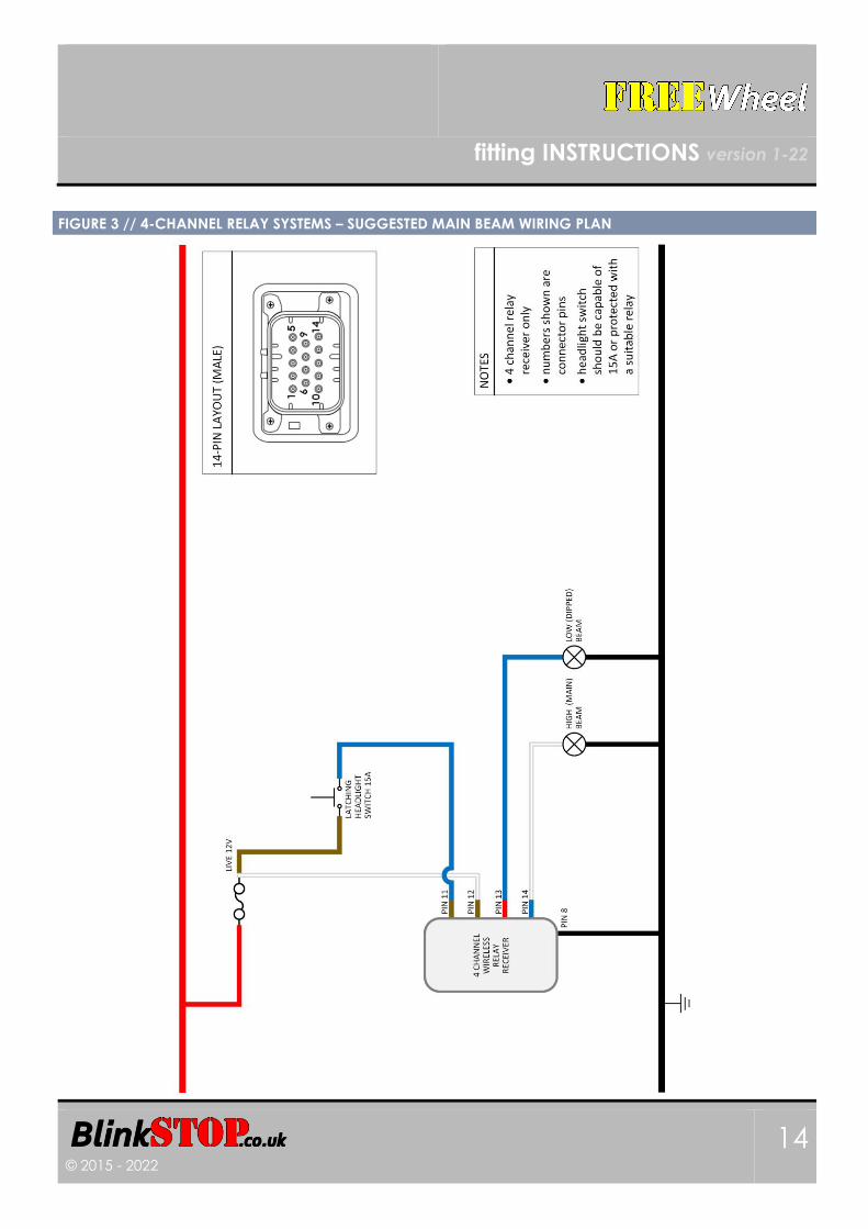
INTEGRATED BeamSTOP HEADLIGHT FUNCTION
CHANNEL 3 SET TO [MAIN]
INSTRUCTIONS FOR OPERATION
BeamSTOP allows full control of headlight main (high) beam and dipped (low) beam.
If the headlights are OFF, BeamSTOP allows the main beam to light for the duration of the button press. This
makes it useful for giving a warning flash to other road users when needed.
If the headlights are ON, BeamSTOP allows each button press to alternate between latched-dipped and
latched-main beam.
For a suggested wiring plan, see Figure 3 (4-channel) and Figure 4 (8-channel) on the following pages.
fitting INSTRUCTIONS version 1-22
© 2015 - 2022 14
FIGURE 3 // 4-CHANNEL RELAY SYSTEMS – SUGGESTED MAIN BEAM WIRING PLAN

fitting INSTRUCTIONS version 1-22
© 2015 - 2022 15
FIGURE 4 // 8-CHANNEL RELAY SYSTEMS – SUGGESTED MAIN BEAM WIRING PLAN

fitting INSTRUCTIONS version 1-22
© 2015 - 2022 16
INTEGRATED FOG LIGHT ‘IVA’ FUNCTION
CHANNEL 4 SET TO [FOG]
INSTRUCTIONS FOR OPERATION
Channel 4 can be used as an auto-cancelling fog light channel. When the headlights are OFF, the fog
light will automatically cancel and is inhibited from operation.
WIRING
When the steering wheel button is pressed, to ensure the fog light will only activate if the headlights are
ON, connect the blue/brown wire to the headlight switch, as shown in Figure 3 (4-channel, pin 11) and
Figure 4 (8-channel, pin 5).
INVERTED MOMENTARY FUNCTION
CHANNELS 5, 6 AND / OR 7 SET TO MOMENTARY [INVERTED]
INSTRUCTIONS FOR OPERATION
Channels 5, 6 and 7 can be used as inverted momentary switched channels, i.e. normally closed. Each
channel can be configured independently and will always be open at power up, with normally closed
behaviour starting once power-on checks are completed (<50ms).
WIRING
No additional wiring is necessary.

fitting INSTRUCTIONS version 1-22
© 2015 - 2022 17
GUARANTEE
All our products come with a two-year guarantee, except our batteries which have a five-
year guarantee.
RETURNS & EXCHANGES You can return many of our products within 14 days from delivery, however customised
goods and bespoke hardware, firmware and software cannot be returned or exchanged.
GOT A PROBLEM OR CHANGED YOUR MIND?
In all cases, we will be reasonable and responsive and will endeavour to give an excellent
service. Please see blinkstop.co.uk/shop for further details.
Contact:
Another quality product from