Embed Size (px)
Citation preview

USER AND INSTALLATION
MANUAL
of the hydraulically adjustable flight propeller
PowerMax
Serial no.: ……………………
TL-ULTRALIGHT s.r.o.
Airport 515, Pouchov
503 41 Hradec Kralove
CZECH REPUBLIC
Tel.: +420 495 218 910
Fax.: +420 495 213 378
www.tl-ultralight.com

Intentionally blank
2/28

Content
Content ..............................................................................................................................3
List of changes ..................................................................................................................5
General information ..........................................................................................................6
1. Introduction ...................................................................................................................6
2. Certification ..................................................................................................................6
3. Alerts, warnings and notes ...........................................................................................7
4. Description and determination of the propeller ............................................................7
5. Technical datas..............................................................................................................8
6. Propeller control............................................................................................................9
7. Propeller marking..........................................................................................................9
7.1. Propeller hub marking................................................................................................9
7.2. Propeller blade marking ...........................................................................................10
8. Propeller construction .................................................................................................10
8.1. Blades .......................................................................................................................10
8.2. Propeller hub ............................................................................................................11
8.3. Pitch control mechanism ..........................................................................................12
8.4. Pitch control servo motor subassembly ...................................................................12
8.5. Propeller spinner ......................................................................................................13
9. Emergency procedures ................................................................................................14
9.1. Vibrations .................................................................................................................14
9.2. Defect in AUTO mode .............................................................................................14
10. Usual procedures .......................................................................................................15
10.1. Pre-flight inspection ...............................................................................................15
11. Propeller service and maintenance ............................................................................16
11.1. Periodic inspections ...............................................................................................16
11.2. Special inspections .................................................................................................16
11.3. General repair.........................................................................................................17
11.4 Cleaning and care ....................................................................................................17
12. Admissible repairs ....................................................................................................18
12.1. Propeller spinner cover ..........................................................................................18
12.2. Change of parts ......................................................................................................18
12.3. Propeller blades repair ...........................................................................................18
13. Possible defects and probable causes ......................................................................19
14. Transport and storing ................................................................................................21
14.1. Propeller transport ..................................................................................................21
14.2. Propeller storing conditions ...................................................................................21
15. Propeller instalation ..................................................................................................22
15.1. Removing the wraping and propeller preservation ................................................22
15.2. Installation of P-AB0-X governor .........................................................................22
15.3 Cleaning of bearing area…………………………….…………………………….24
15.4 Propeller installation onto the propeller boss……….…………………………….24
3/28

15.5. Nut realising ...........................................................................................................24
15.6. Governor max. and min. RPM stop screw releasing .............................................24
15.7. Maximum RPM check ………………………………….……………………….26
15.8. Minimum RPM check ............................................................................................26
15.9. Nut tightening ........................................................................................................27
15.10. Detected speed is lower than given tolerance ......................................................27
15.11. Nut tightening ......................................................................................................28
15.12. Propeller spinner cover ........................................................................................28
15.13. Inspection and record ...........................................................................................28
4/28

List of changes
The user of the propeller is responsible for keeping the manual in force according to the issued
changes. The changes or revisions can be issued only by the producer of the propeller. Up-dating of
the manual is recorded in following table. Valid revision of this manual, so as the service bulletins and
service advicements are available free on www.tl-ultralight.com.
No of change. Date of issue Revised pages Date of insert Signature
1 28.5.2012 1, 8, 11, 29 – 31, 34 28.5.2012 Zahálka
2 1.5.2014 1, 7-11 1.5.2014 Tláskal
5/28

General information
1. Introduction
The aim of this user and installation manual issued by the producer of the propeller is to
introduce the hydraulically adjustable propeller PowerMax. The manual provides basic information for
usage, maintenance and installation of the propeller and its accessories. This information shall ensure
the user the most effective utilization of the propeller. All actions releating to the operation,
installation and maintenace of the propeller must be done according to this manual. The actions not
mentioned in this manual can be realized only by the producer or authorized service. The manual is
divided thematically into the individual parts which are further divided into points according to the
importance and relevance of the processed topic.
WARNING:
This product is designed for installation on the aircraft falling into the category of sports flying
appliances. It is not subject to approval of Civil Aviation Authority Czech Republic and it is
operated on user´s own risk.
NOTE:
Illustrations, pictures and drawings in this manual only serve as an example of displayed object and
cannot be considered for a product or its part as binding.
2. Certification
This propeller was approved by the Light Aircraft Association of Czech Republic according to
the regulation UL-2 „Airworthiness requests SLZ“. Type certificate no. ULL 05 / 2012 was issued on
10. 4. 2012.
.
6/28

3. Alerts, warnings and notes
Following definitions are specified for alerts, warnings and notes in the manual:
ALERT:
Overlooking the corresponding procedure leads to an immediate or significant decrease
in flight safety.
WARNING:
Overlooking the corresponding procedure leads to a smaller, shorter or longer decline
in flight safety.
NOTE:
Describes notes of some extra points which are not directly related to flight safety, but
are important or unusual.
4. Description and determination of the propeller
The PoweMax propeller is a 3-blade tractive in-flight adjustable flight propeller. The propeller
hub is from Al alloys and consist of a top and bottom flange with a lid. There are pitch control
mechanisms inside the hub. Hydraulic governor increases the pitch adjusting, in the opposite direction
the propeller blades are adjusted with a resistance of a spring located inside the hub. The blade
consists of a root part made of Al alloys and composite blade itself. The blade is fastened to the hub
using a pair of axial bearings which allow adjusting the pitch. The hydraulic governor and kinematic
gearing of its movement is located out of the hub behind the propeller gear box and adjusting the pitch
is controlled by oil pressure.
The propeller is designed for following types of engine:
Rotax 912 UL 80 HP
Rotax 912 S 100 HP
Rotax 912 iS 100 HP
Rotax 914 115 HP
ALERT:
Installation on other types of engine must be first consulted with the producer
of the propeller.
.
7/28

5. Technical datas
Sense of rotation To the left (from the front view)
Propeller installation orientation Tractive
No. of blades 3
Diameter 1748 mm
Max. absorbed engine power 115 HP
Max. propeller speed 2387 ot/min
Pitch control range 10º
Adjust speed from one extreme position to the
another – with load 4,6 s
Operating temperature range -25 º up to +40 ºC
Weight of propepeller 10,2 kg
Weight of propeller control hyraulic governor 1,25 kg
Weight of propeller´s spin 0,5 kg
Outer diameter of propeller´s spin Ø 235 mm
Diameter of mounting flange Ø 124 mm
Driving pins (pitch circle) Ø 13 mm (101,6 mm)
Fixing screws M 8
No. of pins/fixing screws 6
Picture no. 1 PowerMax propeller cut
8/28

6. Propeller control
Propeller speed are automatically kept by the electronic controller PR 2 - TL in selected position
(Constant Speed mode) in various flight modes. So the propeller operates in the constant speed mode.
7. Propeller marking
7.1. Propeller hub marking
The number is marked on the front cap of the hub (see an example):
The number is marked on the root part of the blade: (see an example):
NOTE:
The marking code of the propeller except the last symbol must be identical to the code marked on the
propeller hub. Otherwise the propeller was adjusted in an unauthorized way and it is not operated
according to the instructions given by the producer.
9/28

7.2. Propeller blade marking
The number is marked on the root part of the blade: (see an example):
NOTE:
The marking code of the propeller except the last symbol must be identical to the code marked on the
propeller hub. Otherwise the propeller was adjusted in an unauthorized way and it is not operated
according to the instructions given by the producer.
8. Propeller construction
The propeller assembly consists of following main structural units:
1) Propeller blades
2) Propeller hub
3) Pitch control mechanism
4) Pitch control hydraulic governor
5) Two-piece propeller spinner
6) Propeller wiring with control and controller
8.1. Propeller blades
The propeller blades consist of a root part made of steel and carbonic composite blade itself.
These two parts are inseparably joined. The blade´s root part forms the bearing area for a pair of axial
bearings to fasten the blade in the hub and joining area for excentric control of building the blade. The
space between the hub and the blade is protected by a rubber O-ring sealing to avoid entering
of impurities.
10/28

Propeller blade leading edge is protected against the wear-out of the blade in this part by a really
resistent layer. The propeller blade surface is produced in a polished white design, the back side is in
grey dull colour to avoid reflections. The ends of blades are supplied with colour stripes.
Picture no. 2 PowerMax propeller - blade
8.2. Propeller hub
Propeller hub is made from AL alloys and consists of top and bottom flange produced by a
mechanic tooling on CNC machines. The bottom flange is in the part adjacent to the engine controller
supplied with holes fit for installation on engines specified in chapter 4.
Picture no. 3 PowerMax propeller – hub
11/28

8.3. Pitch control mechanism
The pitch control mechanism is hidden inside the propeller hub and its task is to transfer the
advance motion from the hydraulic governor to the pich control. This ensemble is accessible after
dismantling the flange top part with a cap. A spring which ensures adjusting the pitch towards
smaller angles is a part of the subassembly. The construction of the mechanism creates fixed
movement stops of the pitch adjusting.
ALERT:
Keeping the requested tolerances during the pitch control mechanism assembly is possible only
by the producer or authorized service. Other subjects are not allowed for any manipulation with
this subassembly.
Picture no. 4 PowerMax pitch control mechanism
8.4 . Pitch control hydraulic governor subassembly
The hydraulic governor and kinematic gearing of its movement is located out of the propeller on
the the upper front part of the engine. The pitch adjusting is controlled by a oil pressure. The complete
subassembly of the hydraulic governor is installed on the propeller gear box.
12/28

Picture no. 5 PowerMax pitch control hydraulic governor
8.5. Propeller spiner
The propeller spinner consists of a base and a conical cover. Both parts are producer from glass-
carbon composite materials. The propeller spinner is supplied in various colours according to the
customer´s request.
Picture no. 6 Two-piece PowerMax propeller spinner
NOTE:
The propeller producer recommends to provide the aircraft with a manifold pressure instrument.
Adjusting the pitch to the appropriate modes may be selected according to the values on this indicator.
So there is no excessive engine stress and uneconomic operation of the whole driving systém.
13/28
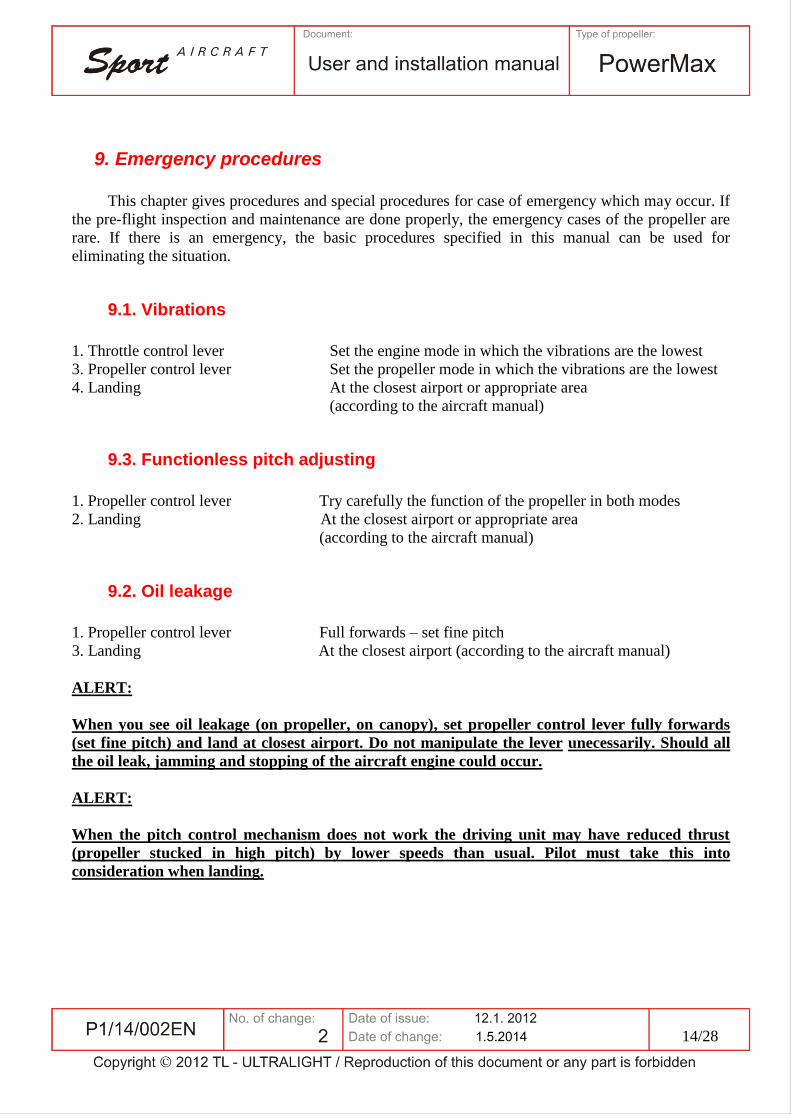
9. Emergency procedures
This chapter gives procedures and special procedures for case of emergency which may occur. If
the pre-flight inspection and maintenance are done properly, the emergency cases of the propeller are
rare. If there is an emergency, the basic procedures specified in this manual can be used for
eliminating the situation.
9.1. Vibrations
1. Throttle control lever Set the engine mode in which the vibrations are the lowest
3. Propeller control lever Set the propeller mode in which the vibrations are the lowest
4. Landing At the closest airport or appropriate area
(according to the aircraft manual)
9.3. Functionless pitch adjusting
1. Propeller control lever Try carefully the function of the propeller in both modes
2. Landing At the closest airport or appropriate area
(according to the aircraft manual)
9.2. Oil leakage
1. Propeller control lever Full forwards – set fine pitch
3. Landing At the closest airport (according to the aircraft manual)
ALERT:
When you see oil leakage (on propeller, on canopy), set propeller control lever fully forwards
(set fine pitch) and land at closest airport. Do not manipulate the lever unecessarily. Should all
the oil leak, jamming and stopping of the aircraft engine could occur.
ALERT:
When the pitch control mechanism does not work the driving unit may have reduced thrust
(propeller stucked in high pitch) by lower speeds than usual. Pilot must take this into
consideration when landing.
14/28

10. Usual procedures
10.1. Pre-flight inspection
Do the inspection systematically before every flight.
1. Propeller blades
Visual check of propeller blades focused on defects (eg. chipped edge etc.) or cracks on the
leading and trailing edges and root part.
2. Propeller blades mounting
Check of mounting the blades in the hub. The mounting must be without apparent backlash
and without oil leakage.
3. Propeller spinner
Visual check of the spinner and its mounting to the propeller focused on the defects and
unwanted releasing.
4. Check of propeller mounting
Check of propeller condition and strenght of mounting to the engine controller and without
oil leakage.
5. Check of pitch adjusting
Check of pitch adjusting in the complete range (focused on time needed for adjusting the
pitch to the extreme position) after switching on the engine.
ALERT:
Any manipulation with the aircraft via the propeller (eg. wheeling or towing the aircraft via
propeller blades) is prohibited. The propeller is not designed for this activity and could be
damaged which will significantly influence its safety during next flight operation.
15/28

11. Propeller service and maintenance
This chapter contains procedures for proper ground service and maintenance of the propeller
recommended and prescribed by the producer. The requests for inspections and maintenance are
defined so as the propeller achieves requested outputs and reliability. Realizing by the producer
prescribed inspections is a condition for the warranty of the propeller.
11.1. Periodics inspections
All activities mentioned in this chapter can be realized only by persons or subjects with
corresponding qualification.
Inspection Time of operation (h)
- period
Provided by Note
500 hour inspection - every 500 ± 5 hours
of operation provozu
Service centre or
producer
Disassembly of
the aircraft
needed
When good operating practices are observed the governor assembly will require complete
overhaul only at regular engine overhaul time. Engine oil changes at frequent periods will greatly
extend the useful life of the governor and engine.
WARNING:
Records about the realised inspections must be confirmed in the propeller record book.
11.2. Special inspections
Special inspections may be requested by the producer in case of untypical installation or usage of
the propeller.
If the propeller speed are exceeded by 10% above the take-off speed for a short term, the
authorized mechanic must eliminate the cause of the defect and realize a special inspection.
If the speed are exceeded by 10% above the take-off speed during the operation, the propeller
must be immediatelly put out of operation and sent to the producer for general repair. Send the
propeller with a detailed report specifying the cause of speed stalling and the values.
16/28

WARNING:
Record about the realised special inspection must be confirmed in the propeller record book.
11.3. General repair
The first general repair must be done after 1500 hours of operation or after 10 years from the
propeller´s production date (date of production is a part of the propeller serial no). General repair is
realised entirely by the producer of the propeller. Subsequent periodic control system is identical to the
system of a newly produced propeller or the residual life is determined according to the propeller
condition.
WARNING:
Record about the realised special inspection must be confirmed in the propeller record book.
11.4 Cleaning and care
NOTE:
The basic cleaning of propeller blades and the spinner can be done by the user according to this
manual.
Clean the exterior surface of propeller blades and the spinner with a cloth damped in tepid water.
By higher fouling use ordinary autoshampoo with concentration 2-10% according to the level of
fouling and after then wash with pure cold water. Slide protecting covers onto the blades after every
ending of flight day.
ALERT:
Do not press on the propeller blades and the spinner when cleaning them and do not use
pressure water. It could cause unwanted changes in settings of propeller geometry.
Use of other cleaning agents and diluents is prohibited.
17/28

12. Admissible repairs
The user of the propeller is allowed to make only the below mentioned repairs. Other repairs
must be realised by the producer, authorized mechanic or authorized service centre.
12.1. Propeller spinner cover
The cover of propeller spinner can be dismantled easily after removing 9 screws placed on the
cover girth. Centre axially the cover of propeller spinner during assembly. The admissible repairs are
not valid for the propeller spinner support. Its disassembly requieres complete disassembly of the
propeller which can be done only by the authorized mechanic.
12.2. Change of parts
The user can change following parts which were supplied by the producer of the propeller: cover
of propeller spinner, cabling and propeller control lever.
12.3. Propeller blades repair
The user is allowed to repair only small defects of the protecting slat on the leading edge of
propeller´s composite blade part. The maximum size of such repair (chipped mass) done by the user is
3 mm. Repair process:
1. Clean and ungrease the damaged place.
2. Fill in the chipped edge with epoxid resin and let it harden.
ALERT:
Do not use local sources (eg. hairdrier) for speeding the process of resin hardening. The
propeller blade surface or its finish may be damaged.
3. Regrind the filled place to the shape of propeller blade profile using the sanding paper.
4. Create the protecting layer of paint in the place of repair.
ALERT:
The propeller blades are statically and dynamically balanced from the production. When
repairing take notice of not influencing this balance.
18/28

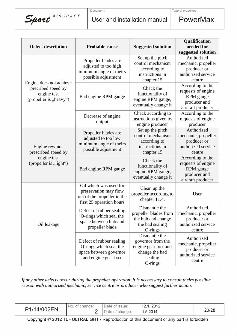
13. Possible defects and probable causes
Following possible defects may appear during the propeller´s operation and may have described
probabale causes and possible solutions of elimination.
Defect description Probable cause Suggested solution
Qualification
needed for
suggested solution
Vibrations during flight
or on the ground
Static unbalance of the
propeller
Check the condition
of propeller blades,
focus on chipped or
broken off parts or
damaged surface
Authorized
mechanic who
solves the possible
defect according to
the procedures
discussed with the
producer or the
authorized service
centre
Aerodynamic unbalance
of the propeller
Check the
functionality of
adjusting the pitch,
focus on smooth and
relative
synchronisation of
adjusting. Do the
check on ground with
engine turned off.
Authorized
mechanic who
solves the possible
issue with adjusting
the pitch according
to the procedures
discussed with the
producer or the
authorized service
centre
Engine defect or
releasing of engine
bedding
Procedure according
to the
recommendations of
engine or aircraft
producer
According to the
requests of engine
or aircraft producer
Propeller blades do not
adjust to the requested
positions
Defect on pitch control
mechanism, wiring or
hydraulic governon
Dismantle the pitch
control mechanism,
check accuracy and
function of wiring,
try function of
hydraulic governor
Authorized service
centre or producer
19/28
Defect description Probable cause Suggested solution
Qualification
needed for
suggested solution
Engine does not achieve
precribed speed by
engine test
(propeller is „heavy“)
Propeller blades are
adjusted to too high
minimum angle of theirs
possible adjustment
Set up the pitch
control mechanism
according to
instructions in
chapter 15
Authorized
mechanic, propeller
producer or
authorized service
centre
Bad engine RPM gauge
Check the
functionality of
engine RPM gauge,
eventually change it
According to the
requests of engine
RPM gauge
producer and
aircraft producer
Decrease of engine
output
Check according to
instructions given by
engine producer
According to the
requests of engine
producer
Engine rewinds
prescribed speed by
engine test
(propeller is „light“)
Propeller blades are
adjusted to too low
minimum angle of theirs
possible adjustment
Set up the pitch
control mechanism
according to
instructions in
chapter 15
Authorized
mechanic, propeller
producer or
authorized service
centre
Bad engine RPM gauge
Check the
functionality of
engine RPM gauge,
eventually change it
According to the
requests of engine
RPM gauge
producer and
aircraft producer
Oil leakage
Oil which was used for
preservation may flow
out of the propeller in the
first 25 operation hours
Clean up the
propeller according to
chapter 11.4.
User
Defect of rubber sealing
O-rings which seal the
space between hub and
propeller blade
Dismantle the
propeller blades from
the hub and change
the bad sealing
O-rings
Authorized
mechanic, propeller
producer or
authorized service
centre
Defect of rubber sealing
O-rings which seal the
space between governor
and engine gear box
Dismantle the
governor from the
engine gear box and
change the bad
sealing
O-rings
Authorized
mechanic, propeller
producer or
authorized service
centre
If any other defects occur during the propeller operation, it is neccessary to consult theirs possible
reason with authorized mechanic, service centre or producer who suggest further action.
20/28

14. Transport and storing
This chapter adjusts by the producer prescribed instructions for propeller transport and storing.
14.1. Propeller transport
The propeller is always supplied as ready-made, except the pitch control hydraulic governor
subassembly, which must be separately installed.
NOTE:
The propeller may be transported to the producer dismantled. The producer is not responsible for any
damages caused by the transport or by the unappropriate fixing and placing in a box.
14.2. Propeller storing conditions
A newly produced propeller or propeller after general repair is preserved from the production.
Store it in original wraping in a clean and dry room heated during winter and slighty ventilated. There
must not be stored chemicals affecting harmfully the propeller and the blades in the same room. Sharp
temperature fluctuation is inadmissible. The wraping must be stored in bulk, at least 20 cm above the
floor od from the room walls.
Table of requested climatic conditions for propeller storing
Temperature range +5 to + 40 ºC
Relative humidity range 45 to 75 %
Propeller with removed original wraping store like this:
1. In a horizontal position with the propeller hub flange laid on a pad and fixed with six
screws M 8. The propeller blades must not be in touch or be supported with any objects.
The propeller blades must be covered with protective sleeves.
2. In a vertical position fixed properly with six screws M 8 on the wall. The propeller
blades must not be in touch or be supported with any objects. The propeller blades must
be covered with protective sleeves.
ALERT:
It is forbidden to store the propeller laying ends of two blades on the ground and the third blade
leaned on e.g. the wall. This position could affect the geometry of blades adjusting.
21/28

15. Propeller installation
This chapter provides by the producer prescribed instructions for propeller installation onto the
propeller boss, wiring of control system and pitch control mechanism.
WARNING:
Propeller can be installed on the aircraft only by authorized mechanic, authorized service centre
or producer.
NOTE:
Propeller is designed only for installation onto the engines according to chapter 4.
15.1. Removing of wraping and propeller preservation
Remove the wraping and propeller preservation and get it out from the transportation box. Check
the condition, eventual damages or deformations of the supplied propeller. Check if the supply is
complete.
15.2. Installation of P-AB0-X governor
Install the P-AB0-X governor (see operation and installation manual for constant speed propeller
governors, P-ROV-514/01). Instal the bowden bracket and connect the cable with governor control
lever (via fork, pin, washer and cotter pin).
22/28
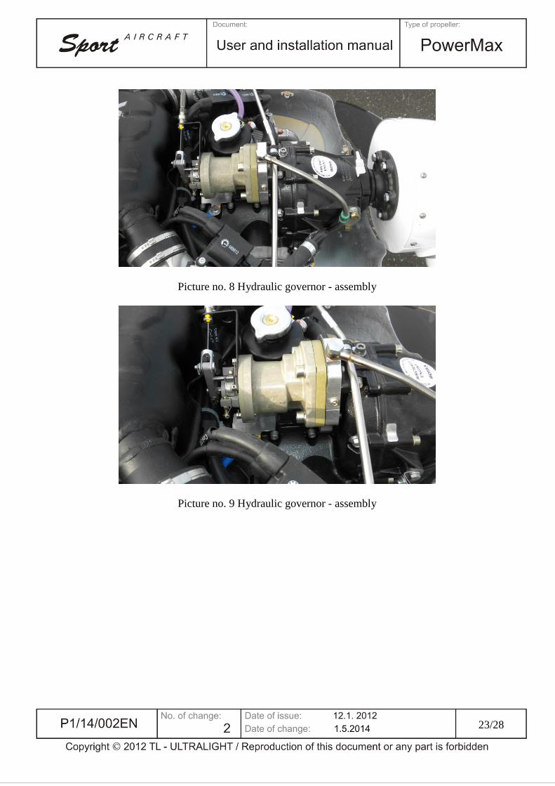
Picture no. 8 Hydraulic governor - assembly
Picture no. 9 Hydraulic governor - assembly
23/28

15.3. Cleaning of bearing area
Clean the bearing area of propeller hub flange with centre recess. Clean the bearing area of
propeller hub flange with centre area. Check condition of bearing area.
15.4. Propeller installation onto the propeller boss
Put the composite base of propeller hub onto the propeller boss and fix the senary of follower
pins into the recess in reducer flange. Insert a sealing 47/4 sealing O-ring between the propeller hub
surfaces and the engine flange. Finally put the built-up propeller onto the propeller boss with base of
propeller spinner. Set the propeller hub position so as the holes for follower pins are aligned and put
the propeller hub on them. Fix the joint of propeller and engine with senary of screws M 8 x 40 8.8
ISO 4014 and secure them with metal nuts VM 8 DIN 980 with washers. Tighten the screws according
to following instruction scheme with requested tightening torque.
ALERT:
Check and tighten properly the screws and nuts after every propeller installation when
achieving first 25 operation hours. Partial loss of assembly overlap in the joint of flange and
propeller hub may occur after this period. Which could endanger the operation safety.
Picture no. 16 Sequence of procedure for tightening the screws
Tightening torque of screws joining
propeller with propeller boss 23,5 N.m
24/28

Picture no. 17 Propeller installation onto the propeller boss
15.5. Nut releasing
Release the nut M 12 marked in the following picture.
WARNING:
Do not remove completely the nut M 12 from the axis of pitch control mechanism, only release it.
Picture no. 18 Nut M 12 releasing
25/28

15.6. Governor max. and min. RPM stop screw releasing
Release min. RPM stop screw and max. RPM stop screw on governor.
15.7. Maximum RPM check
Remove the textile protective sleeves from the propeller. Start up the engine and check carefully
RPM by maximum engine output. Set the full fine pitch. Engine speeds must be 5575 ± 200 RPM in
this mode. Keep the blade adjustment pitch set in this position and turn off the engine. Adjust the max.
RPM stop screw so that it makes contact with the governor control lever arm in the identified position.
Secure the RPM stop screw in this position.
15.8. Minimum RPM check
Start up the engine and check carefully RPM in maximum blade adjustment angle. RPM must be
4200 ± 200 RPM in this mode. Keep the blade adjustment pitch set in this position and turn off the
engine. Adjust the max. RPM stop screw so that it makes contact with the governor control lever
arm in the identified position. Secure the RPM stop screw in this position.
26/28

15.9. Nut tightening
If the engine speed with installed propeller justify the requests specified in point 15.7 and 15.8.
propeller installation onto the aircraft, tighten the nut M 12 marked in the following picture.
WARNING:
Do not tighten the nut M 12 using a force, the washer between the lid of propeller hub and this
nut must rotate freely.
15.10. Adjusting the propeller control lever
Nastavte upevnění lanka bovdenu na páku ovládání tak, aby její pohyb byl po celé délce drážky
ve výřezu ve sloupku. V krajních polohách se nesmí páka dotýkat plechu.
27/28

15.11. Propeller spinner cover
Install the propeller spinner cover onto the propeller spinner base using 9 screws located around
the cover. By assembly centre axially the propeller spinner cover.
15.12. Inspection and record
Test again correct propeller functionality. Check the bond of the propeller with the engine flange
for oil leaks. Write a note of propeller installation with date and aircraft immatriculation in the
propeller record book. The installation must be signed by an authorized mechanic in the propeller
record book.
28/28

Date Aircraft Total hours
in service Records
Records
by
1/5

Date Aircraft Total hours
in service Records
Records
by
2/5

Date Aircraft Total hours
in service Records
Records
by
3/5

Date Aircraft Total hours
in service Records
Records
by
4/5

Date Aircraft Total hours
in service Records
Records
by
5/5