Embed Size (px)
Citation preview

EPA
United States Office of Research Environmental Protection and Development April 2001 Agency Washington DC 45260
EPA 600/4-84/013 (N14)
USEPA Manual of Methods for Virology
Chapter 14April 2001

April 2001
Chapter 14CONCENTRATION AND PROCESSING OF WATERBORNE VIRUSES BY POSITIVE CHARGE
1MDS CARTRIDGE FILTERS AND ORGANIC FLOCCULATION1
1. Introduction
1.1 Scope This chapter describes the most
widely used virus adsorption-elution (VIRADEL) method for recovering human enteric viruses from water matrices (Fout et al., 1996). The method takes advantage of positively charged cartridge filters to concentrate viruses from water. The major advantage of methods that use these filters over those de-scribed in Chapters 5 and 6 that use negatively charged filters is that additives are not normally needed to achieve virus adsorption to filters.
1.2 Significance Human pathogenic enteric viruses
can be present in surface or ground-waters impacted by untreated or inadequately treated domestic wastes. The presence of these viruses can cause hepatitis, gastroenteritis and numerous other diseases.
The surface water treatment rule (40 CFR Part 141) established the maxi-mum contamination level for enteric virus in public water systems by requiring that systems using surface water or ground water under the influence of surface water reduce the amount of virus in source water by 99.99%. The rule requirements are currently met on basis of treatment alone, and thus the degree of actual protection against waterborne viral disease depends upon the source water quality. The actual degree of protection can only be estimated by monitoring source and finished waters over an extended period of time.
The amount of environmental water that must be sampled depends upon expected virus concentrations. In general,
it is recommended that one liter of highly contaminated waters such as sewage to 1,800 liters of drinking waters should passed through a 1MDS cartridge filter.
1.3 Safety The water samples to be monitored
may contain pathogenic human enteric viruses. Laboratories performing virus analyses are responsible for establishing an adequate safety plan and must rigorously follow the guidelines on decontamination and waste disposal given in Chapter 2 (May 1991 revision).
2. Apparatus, Materials, Media and Reagents
Analytical Reagent or ACS grade chemicals (unless specified otherwise) and deionized or distilled reagent grade water (dH2O) should be used to prepare all media and reagents. The dH2O must have a resistance of greater than 0.5 megohms-cm at 25°C, but water with a resistance of 18 megohms-cm is preferred.
Appendix 1 gives a list of potential vendors for the apparatus, materials, media and reagents used in this method. Equivalent items from other vendors may be substituted for those given in the text.
2.1 Sampling Apparatus and Materials Several configurations are given
below for the assembly of the filter apparatus. The standard filter apparatus is used for all sampling, except where a prefilter, dechlorination or pH adjustment are required.
2.1.1 Standard filter apparatus (see Figure 14-1)
(a) Materials Letters in bold print represent the
origin of the abbreviations used to identify parts in the figures.
(a.1) One BR — Backflow Regulator (Watts Regulator Product Series 8 — ¾" Hose Connection Vacuum Breaker).
(a.2) Three SF — Swivel Female insert with garden hose threads (United States Plastic Product No. 63003).
(a.3) Three sections of BT — Braided Tubing, ½" clear (Cole-Parmer Product No. P-95636-02).
(a.4) Six HC1 — Hose Clamps (Cole-Parmer Product No. P-06403-20).
(a.5) One HF1 — Hose Fitting, nylon, d" male NPT × ½" tubing ID (United States Plastic Product No. 61141).
(a.6) One PR — Pressure Regulator (Watts Regulator Product No. d" 26A (or 263A), Suffix B).
(a.7) One PN — PVC Nipple, d" male NPT (Ryan Herco Product No. 3861-057; not required with the 263A regulator).
(a.8) One TE — PVC TEE with d" female NPT ports (Ryan Herco Product No. 3805-003; not required with the 263A regulator).
(a.9) One RB1 — Reducing Bushing, d" NPT(M) × ¼" NPT(F) (Cole-Parmer Product No. P-06349-32; not required with the 263A regulator).
(a.10) One PG — Pressure Gauge 0-60 pound per square inch (PSI; Cole-Par-
1Prepared by G. Shay Fout, D.R. Dahling and R.S. Safferman
14-1

April 2001
Figure 14-1 Standard Filter Apparatus
mer Product No. P-68004-03; place in¼" gauge port if using the 263A regulator).
(a.11) One RA — Reducing Adaptor,½" female NPT × d" male NPT (Cincinnati Valve and Fitting Product No.SS-8-RA-6).
(a.12) One MQ1 — Male Quick Connect, ½" male NPT (Cincinnati Valveand Fitting Product No. SS-QF8-S-8PMor Cole-Parmer Product No. P-31303-36; appropriate hose fittings and braided tubing can be substituted for quickconnects).
(a.13) Two FQ1 — Female Quick Connects, ½" female NPT (CincinnatiValve and Fitting Product No. SS-QF8-B-8PF; Cole-Parmer Product No. P-31303-01 may be used by substitutingthe two reducing nipples (item a.14) fortwo reducing bushings (¾" male NPT × ½" female NPT; Cole-Parmer Product No. P-06349-35)).
(a.14) Two RN1 — Reducing Nipples,¾" male NPT × ½" male NPT (Cole-Parmer Product No. P-06349-87).
(a.15) One CH — Cartridge Housingwith wench (Cuno Product No. AP11Tor 44857-05).
(a.16) One FC — Filter Cartridge, positively charged 1MDS, ZetaPor Virosorb(Cuno Product No. 45144-01-1MDS).
(a.17) One MQ2 — Male Quick Connect, ½" female NPT (Cincinnati Valveand Fitting Product No. SS-QF8-S-8PF;Cole-Parmer Product No. P-31303-36 may be used by substituting the hosefitting (item a.18) for a ½" female NPT × ½"tubing ID hose fitting (Cole-Parmer Product No. P-06464-10)).
(a.18) One HF2 — Hose Fitting, ½" male NPT × ½"tubing ID (United StatesPlastic Product No. 62142).
(a.19) One WM — Water Meter (Neptune Equipment Product No. e" Trident 10).
The water meter should be used in a horizontal position and protectedfrom freezing. The order should specifythat meters be rated in gallons (1 gal =0.1337 ft3 or 3.7854 L). If not specified,meters may be rated in cubic feet (1 ft3 = 7.481 gal or 28.316 L).
(a.20) One HF3 — Hose Fitting, nylon, ¾" male NPT × ½" tubing ID (United States Plastic Product No. 61143).
(a.21) One FV — Flow Control Valve (Plast-O-Matic Valves Product No. FC075B-3-PVC).
(b) Apparatus assembly The standard filter apparatus con
sists of three modules: the regulator module, the cartridge housing module and the discharge module.
Teflon tape (Cole-Parmer Product No. P-08782-27) must be used on all threaded, non-compression fittings.
(b.1) Regulator module — in order, as shown in Figure 14-1, connect the backflow regulator (BR) to a swivel female insert (SF). Clamp a piece of braided tubing (BT) onto the tubing connector of the swivel female insert using a hose clamp (HC1). Clamp the other end of the tubing to a d × ½" hose fitting (HF1). Screw the fitting into the inlet of the pressure regulator (PR). Connect the outlet of the pressure regulator to the PVC TEE (TE) via a PVC nipple (PN). Connect the pressure gauge (PG) to the top of the PVC TEE using the reducing bushing (RB1). At-tach a reducing adaptor (RA) to the remaining connection on the PVC TEE. Add a male quick connect (MQ1) to the reducing adaptor.
(b.2) Cartridge housing module — Attach a female quick connect (FQ1) to a reducing nipple (RN1). Connect the reducing nipple to the inlet of the cartridge housing (CH). Attach another reducing nipple to the outlet of the housing. Attach a male quick connect (MQ2) to the reducing adaptor.
(b.3) Discharge module — attach a female quick connect (FQ1) to a hose fitting (HF2). Connect a piece of braided tubing (BT) to the hose fitting (HF2) with a hose clamp (HC1). Clamp the other end of the braided tubing to a swivel female insert (SF) with another hose clamp (HC1). Attach the swivel female insert (SF) to the inlet of the water meter (WM). Attach another swivel female insert (SF) to the outlet of the water meter (WM) and connect a piece of braided tubing (BT) with a hose clamp (HC1). Clamp the other end of
14-2

April 2001
Figure 14-2 Additional Modules for the Standard Filter Apparatus
the tubing to a hose fitting (HF3) with another hose clamp(HC1). Screw the hose fitting (HF3) into the inlet of the flow control valve (FV). An additional hose fitting (not shown) may be added to the flow control valve for the attachment of a sufficient length of tubing to reach a drain. The discharge module does not have to be sterilized.
(b.4) Connect the cartridge housing module to the regulator module at the quick connect. The combined regulator and cartridge housing modules should be sterilized with chlorine as described in section 2.1.1a.10, 2.3.2. Presterilize a 1MDS filter cartridge (FC) as de-scribed in section 2.3.1 and place it into the cartridge housing using aseptic technique. Replace the housing head of the cartridge housing and tighten with a cartridge housing wench. Check to en-sure that the filter is adequately sealed by shaking the housing. Adequately sealed filters should not move. For convenience during shipping, the regulator and cartridge housing modules may be separated. Seal all openings into the modules with sterile aluminum foil.
2.1.2 Prefilter module (see Figure 14-2)
Use the prefilter module for waters exceeding 75 nephelometric turbidity units (NTU) or for other conditions that prevent the minimum sampling volumes from being obtained.
(a) Additional materials: One PC — 10 :m Polypropylene Prefilter Cartridge (Parker Hannifin Product No. M19R10-A); in addition, a female quick connect (FQ1), two reducing nipples (RN1), a cartridge housing (CH) and a male quick connect (MQ2) as described for the standard apparatus are needed.
(b) Module assembly — in order, as shown for the prefilter module in Figure 14-2, attach a female quick connect (FQ1) to a reducing nipple (RN1). Connect the reducing nipple to the inlet of the cartridge housing (CH). Attach another reducing nipple to the outlet of the housing. Attach a male quick connect (MQ2) to the reducing adaptor. Sterilize the unit with chlorine as de-scribed in section 2.1.1a.10, 2.3.2 and add a presterilized polypropylene prefilter cartridge using aseptic technique.
Cover the ends with sterile aluminum foil.
2.1.3 Injector modules (see Figure 14-2)
Use injector modules for source or finished water requiring pH reduction and for finished waters requiring dechlorination. Both single and double injector modules should be assembled so that they will be available on demand.
(a) Materials:
(a.1) Two FQ2 — Female Quick Connects, ½" male NPT (Cincinnati Valve and Fitting Product No. SS-QF8-B-8PM).
(a.2) Four ME — Male Elbows, d" male NPT (Cincinnati Valve and Fitting Product No. SS-6-ME).
(a.3) Two RN2 — Reducing Nipples, d" male NPT × ½" male NPT (Cole-Parmer Product No. P-06349-85).
(a.4) Two RB2 — Reducing Bushings, d" female NPT × ½" male NPT (Cole-Parmer Product No. P-06349-34).
(a.5) Three IN — In-line INjectors (DEMA Engineering Product No. 203B d" female NPT; a metering or peristaltic pump and appropriate connectors may be substituted for an injector).
The use of injectors significantly reduces the cost per apparatus. Injectors can be used in the absence of an electricity source, but are much more difficult to control than pumps. If pumps are selected, use a check valve (e.g., Cole-Parmer Cat. No. P-98676-00) on tubing between the pump and the main body of the module.
(a.6) Three HC2 — Hose Clamps (Cole-Parmer Product No. P-06403-10).
(a.7) In addition to the items specified in sections 2.1.3a.1 to 2.1.3a.6, four reducing adaptors (RA), four PVC TEEs (TE), two PVC nipples (PN), two reducing bushings (RB1), two pressure
14-3

April 2001
gauges (PG), two female quick connects (FQ1), two male quick connects (MQ1) and two male quick connects (MQ2) as described for the standard apparatus are needed. Two union ball joints, d" female NPT (not shown; Cincinnati Valve and Fitting Product No. SS-6-UBJ) and two PVC nipples may be used in place of the two reducing nipples (RN2), male quick connects (MQ2), female quick connects (FQ1) and reducing bushings (RB2) used with the double injector module.
(b) Module assembly:
(b.1) Single Injector Module — assemble the parts in order as shown for the single injector module in Figure 14-2. Attach a female quick connect (FQ2) to a reducing adaptor (RA). Connect the adaptor to the inlet of the injector (IN). Connect the outlet of the injector to a PVC TEE (TE) via a PVC nipple (PN). Connect a pressure gauge (PG) to the top of the PVC TEE using a reducing bushing (RB1). Attach a reducing adaptor (RA) to the remaining connection on the PVC TEE. Add a male quick connect (MQ1) to the reducing adaptor.
(b.2) Double Injector Module — as-assemble the parts as shown for the double injector module in Figure 14-2. Assemble the main portion by attachinga female quick connect (FQ2) to a reducing adaptor (RA). Connect the adaptor to the top connector of a PVCTEE (TE). Add a male elbow (ME) toone of the connections on the PVC TEE. Attach a reducing nipple (RN2)to the other connection. If using a union ball joint in place of the quick connects, attach a PVC nipple (not shown)to the other connection. Add a male quick connect (MQ2) to the reducingnipple or add one portion of a union balljoint (not shown) to the PVC nipple.Connect the inlet side of an injector(IN) to the male elbow. Attach another male elbow to the outlet of the injector.Connect the male elbow to another PVC TEE. Connect a reducing nipple (RN2or PVC nipple) to the other end of thesecond PVC TEE. Add a male quick
connect (MQ2) to the reducing nippleas above (or add one portion of the second union ball joint to the PVC nipple).Connect the top connector of the secondPVC TEE to a third PVC TEE via a PVC nipple (PN). Connect a pressuregauge (PG) to the top of the third PVCTEE using a reducing bushing (RB1).Attach a reducing adaptor (RA) to the remaining connection on the third PVCTEE. Add a male quick connect (MQ1)to the reducing adaptor. Attach two male elbows (ME) to the inlet and outletof a second injector (IN). Connect two reducing bushings (RB2) or, if used, thebottom portion or the two union balljoints (not shown) to the male elbows. Connect a female quick connect (FQ1)to each reducing bushing. Orient the second injector so that the direction offlow is the same as the first injector (thearrows on the injectors should bothpoint towards the pressure gauge side ofthe assembly). Connect the two female quick connects to the male quick connects of the main portion to complete the assembly or, if used, connect the twoportions of the union ball joints.
2.1.4 Other Sampling Materials
(a) Portable pH probe (Omega Product No. PHH-1X)
(b) Portable temperature probe (Omega Product No. HH110).
(c) Commercial ice packs (Cole-Parmer Product No. P-06346-76).
(d) One liter polypropylene wide-mouth bottles (Nalgene Product No. 2104-0032).
(e) Insulated shipping box with carrying strap (17" × 17" × 16"; Cole-Parmer Product No. P-03742-00 and P-03742-30).
(f) Miscellaneous — aluminum foil, data card (see Appendix 2), hosecock clamp, surgical gloves, screwdriver or pliers for clamps, waterproof marker.
(g) Chemical resistant pump capable of supplying 30 PSI at 3 gal/min and ap
propriate connectors (for use where gar-den hose-type pressurized taps for the source or finished water to be monitored are unavailable and for QC samples). Follow the manufacturer's recommendations for pump priming.
2.2 Media and Reagents for Sampling Apparatus
2.2.1 0.52% chlorine (HOCl; 5250 mg/L) — add 100 mL of household bleach to 850 mL of dH2O and adjust the pH of the solution to 6-7 with 1 M HCl. Bring to 1 liter with dH2O. Store for up to two weeks at room temperature.
2.2.2 2% sodium thiosulfate (Na2S2O3) — dissolve 100 g of Na2S2O3 in a total of 5000 mL dH2O to prepare a stock solution. Autoclave for 30 min at 121°C.
2.2.3 Hydrochloric acid (HCl) — Pre-pare 0.1, 1 and 5 M solutions by mixing 50, 100 or 50 mL of concentrated HCl with 4950, 900 or 50 mL of dH2O, respectively.
HCl solutions are self-sterilizing, therefore, prepare those solutions to be used for adjusting the pH of water samples at least 24 h before use.
2.3 Sterilization of Sampling Apparatus
2.3.1 1MDS filter cartridges and prefilter cartridges — Presterilize 1MDS filter cartridges and prefilter cartridges by wrapping the filters in Kraft paper and autoclaving at 121°C for 30 min.
2.3.2 Chlorine Sterilization — Sterilize pumps, sampling apparatus modules, injector tubing and plastic bags fortransporting injector tubing by recirculating or immersing the items in 0.52% chlorine for 30 minutes. Drain the chlorine from the objects being sterilized. Dechlorinate by recirculating orimmersing the items in a solution containing 25 mL of 2% thiosulfate perliter of sterile dH2O. Cover the apparatus module ends and the injector port(s)with sterile aluminum foil. Place the
14-4

April 2001
injector tubing in a sterile bag or wrap-ping in such a way that the ends may be removed without contaminating them.
Ensure that the solutions come in full contact with all surfaces when per-forming these procedures.
Used filter apparatus modules should be decontaminated and then cleaned according to the procedures in Chapter 2 before final sterilization.
2.4 Apparatus and Materials for Elution and Organic Flocculation Steps
2.4.1 Positive pressure air or nitrogen source equipped with a pressure gauge.
If the pressure source is a laboratory air line or pump, it must be equipped with an oil filter.
2.4.2 Dispensing pressure vessels — 5 or 20 liter capacity (Millipore Corp. Product No. XX67 00P 05 and XX67 00P 20; see Figure 14-3).
Figure 14-3 Pressure Vessel
2.4.3 pH meter with combination-type electrode and an accuracy of at least 0.1 pH unit.
2.4.4 Autoclavable inner-braided tubing with screw clamps or quick connects for connecting the vacuum source, pressure vessel and cartridge housing.
2.4.5 Magnetic stirrer and stir bars.
2.4.6 Refrigerated centrifuge capable of attaining 2,500 - 10,000 ×g and screw-capped centrifuge bottles with 100 to 1000 mL capacity.
Each bottle must be rated for the relative centrifugal force used.
2.4.7 Sterilizing filter — 0.22 :m Acrodisc filter with prefilter (Gelman Sciences Product No. 4525).
Use sterilizing filter stacks on samples that clog commercial filters. Pre-pare sterilizing filter stacks using 0.22 :m pore size membrane filters (Millipore Corp. Product No. GSWP 47 00) stacked with fiberglass prefilters (Millipore Corp. AP15 47 00 and AP20 47 00). Stack the prefilters and 0.22 :m membrane into a disc filter holder (Millipore Corp. Product No. SX00 47 00) with the AP20 prefilter on top and 0.22 :m membrane filter on bottom. Disassemble the filter stack after each use to check the integrity of the 0.22 :m filter. Refilter any media filtered with a damaged stack.
Always pass about 10 - 20 mL of sterile beef extract, pH 7.0-7.5 (pre-pared as above, without pH adjustment), through the filter just before use. This step will reduce virus adsorption onto the filter membranes.
2.5 Media and Reagents for Elution and Organic Flocculation Steps
2.5.1 Sodium hydroxide (NaOH) — prepare 1 M and 5 M solutions by dissolving 4 g or 20 g of NaOH in a final volume of 100 mL of dH2O, respectively.
NaOH solutions are self-sterilizing and may be stored for several months at room temperature.
2.5.2 Iodine disinfectant, 0.5% — dissolve 5g of iodine in 1000 mL of 70% ethanol.
2.5.3 Beef extract, desiccated powder (Difco Product No. 0115-17-3) — pre-pare buffered 1.5% beef extract by dissolving 30 g of beef extract powder and 7.5 g of glycine (final glycine concentration = 0.05 M) in 1.9 L of dH2O. Adjust the pH to 9.5 with 1 or 5 M NaOH and bring the final volume to 2 L with dH2O. Autoclave at 121°C for 15 min and use at room temperature.
Beef extract solutions may be stored for one week at 4°C or for longer periods at -20°C.
Screen each new lot of beef extract before use to determine whether virus recoveries are adequate. Perform the screening by spiking one liter of beef extract solution with 1 mL of poliovirus containing a known virus concentration ranging between 100 and 200 PFU/mL. Process the spiked sample using the organic flocculation concentration procedure given in section 4.2 and assay the concentrate using the plaque assayprocedure given in Chapter 10 (December 1987 revision). The mean recoveryof poliovirus for three trials should be atleast 50%.
2.5.4 Sodium phosphate, dibasic(Na2HPO4 C 7H2O) — 0.15 M, pH 9.0 -9.5 or 7.0 - 7.5.
Dissolve 40.2 g of sodium phosphate in a final volume of 1000 mLdH2O. The pH of the solution should bebetween 9.0 - 9.5. Adjust the pH to 9.0to 9.5 with NaOH, if necessary, or to7.0 to 7.5 with HCl. Autoclave at 121°C for 15 min.
3. Sample CollectionOperators must wear surgical
gloves and avoid conditions that cancontaminate a sample with virus.Gloves should be changed after touching human skin or handling componentsthat may be contaminated (e.g., watertaps, other environmental surfaces).
3.1 Purge the water tap to be sampled before connecting the filter apparatus (see Figure 14-4). Continue the purging for 2-3 min or until any debris thathas settled in the line has cleared.
Figure 14-4 Purge of Tap
3.1.1 Remove the foil from the back-flow regulator (BR; see Figure 14-1). Loosen the swivel female insert (SF)
14-5
April 2001
slightly to allow it to turn freely andconnect the backflow regulator to the tap. Retighten the swivel female insert. Disconnect the cartridge housing module at the quick connect (MQ1/FQ1), ifconnected, and cover the open end withsterile foil.
3.1.2 Remove the foil from the ends of the discharge module and connect it to the regulator module. Place the control flow valve or tubing connected to the outlet of the flow control valve into a one liter plastic bottle. Note that the injector module, the prefilter module and the cartridge housing module must not be attached to the apparatus at this stage of the procedure!
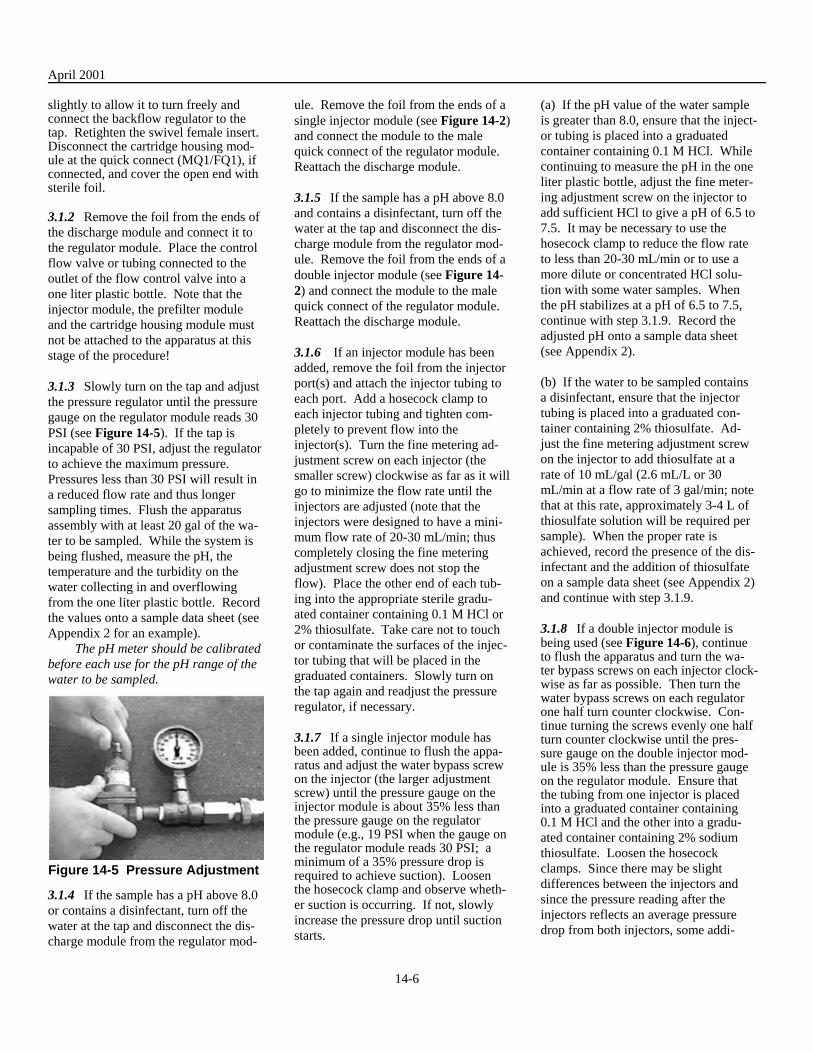
3.1.3 Slowly turn on the tap and adjust the pressure regulator until the pressure gauge on the regulator module reads 30 PSI (see Figure 14-5). If the tap is incapable of 30 PSI, adjust the regulator to achieve the maximum pressure. Pressures less than 30 PSI will result in a reduced flow rate and thus longer sampling times. Flush the apparatus assembly with at least 20 gal of the water to be sampled. While the system is being flushed, measure the pH, the temperature and the turbidity on the water collecting in and overflowing from the one liter plastic bottle. Record the values onto a sample data sheet (see Appendix 2 for an example).
The pH meter should be calibrated before each use for the pH range of the water to be sampled.
Figure 14-5 Pressure Adjustment
3.1.4 If the sample has a pH above 8.0 or contains a disinfectant, turn off the water at the tap and disconnect the discharge module from the regulator mod
ule. Remove the foil from the ends of a single injector module (see Figure 14-2) and connect the module to the male quick connect of the regulator module. Reattach the discharge module.
3.1.5 If the sample has a pH above 8.0 and contains a disinfectant, turn off the water at the tap and disconnect the discharge module from the regulator module. Remove the foil from the ends of a double injector module (see Figure 14-2) and connect the module to the male quick connect of the regulator module. Reattach the discharge module.
3.1.6 If an injector module has been added, remove the foil from the injector port(s) and attach the injector tubing to each port. Add a hosecock clamp to each injector tubing and tighten completely to prevent flow into the injector(s). Turn the fine metering adjustment screw on each injector (the smaller screw) clockwise as far as it will go to minimize the flow rate until the injectors are adjusted (note that the injectors were designed to have a mini-mum flow rate of 20-30 mL/min; thus completely closing the fine metering adjustment screw does not stop the flow). Place the other end of each tubing into the appropriate sterile graduated container containing 0.1 M HCl or 2% thiosulfate. Take care not to touch or contaminate the surfaces of the injector tubing that will be placed in the graduated containers. Slowly turn on the tap again and readjust the pressure regulator, if necessary.
3.1.7 If a single injector module has been added, continue to flush the apparatus and adjust the water bypass screwon the injector (the larger adjustment screw) until the pressure gauge on theinjector module is about 35% less than the pressure gauge on the regulator module (e.g., 19 PSI when the gauge onthe regulator module reads 30 PSI; a minimum of a 35% pressure drop isrequired to achieve suction). Loosen the hosecock clamp and observe whether suction is occurring. If not, slowly increase the pressure drop until suction starts.
(a) If the pH value of the water sample is greater than 8.0, ensure that the inject-or tubing is placed into a graduated container containing 0.1 M HCl. While continuing to measure the pH in the one liter plastic bottle, adjust the fine metering adjustment screw on the injector to add sufficient HCl to give a pH of 6.5 to 7.5. It may be necessary to use the hosecock clamp to reduce the flow rate to less than 20-30 mL/min or to use a more dilute or concentrated HCl solution with some water samples. When the pH stabilizes at a pH of 6.5 to 7.5, continue with step 3.1.9. Record the adjusted pH onto a sample data sheet (see Appendix 2).
(b) If the water to be sampled contains a disinfectant, ensure that the injector tubing is placed into a graduated container containing 2% thiosulfate. Ad-just the fine metering adjustment screw on the injector to add thiosulfate at a rate of 10 mL/gal (2.6 mL/L or 30 mL/min at a flow rate of 3 gal/min; note that at this rate, approximately 3-4 L of thiosulfate solution will be required per sample). When the proper rate is achieved, record the presence of the disinfectant and the addition of thiosulfate on a sample data sheet (see Appendix 2) and continue with step 3.1.9.
3.1.8 If a double injector module is being used (see Figure 14-6), continueto flush the apparatus and turn the water bypass screws on each injector clock-wise as far as possible. Then turn the water bypass screws on each regulatorone half turn counter clockwise. Continue turning the screws evenly one halfturn counter clockwise until the pressure gauge on the double injector module is 35% less than the pressure gaugeon the regulator module. Ensure that the tubing from one injector is placedinto a graduated container containing0.1 M HCl and the other into a graduated container containing 2% sodium thiosulfate. Loosen the hosecock clamps. Since there may be slight differences between the injectors and since the pressure reading after the injectors reflects an average pressure drop from both injectors, some addi-
14-6
April 2001
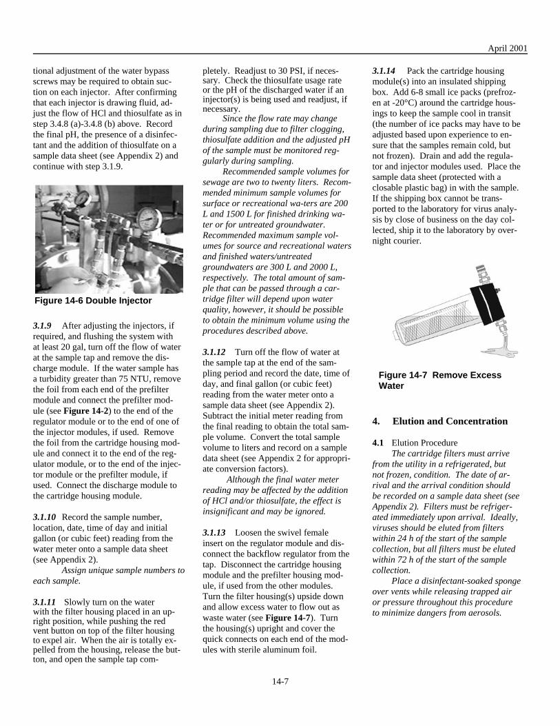
tional adjustment of the water bypass screws may be required to obtain suction on each injector. After confirming that each injector is drawing fluid, ad-just the flow of HCl and thiosulfate as in step 3.4.8 (a)-3.4.8 (b) above. Record the final pH, the presence of a disinfectant and the addition of thiosulfate on a sample data sheet (see Appendix 2) and continue with step 3.1.9.
Figure 14-6 Double Injector
3.1.9 After adjusting the injectors, if required, and flushing the system with at least 20 gal, turn off the flow of water at the sample tap and remove the discharge module. If the water sample has a turbidity greater than 75 NTU, remove the foil from each end of the prefilter module and connect the prefilter module (see Figure 14-2) to the end of the regulator module or to the end of one of the injector modules, if used. Remove the foil from the cartridge housing module and connect it to the end of the regulator module, or to the end of the injector module or the prefilter module, if used. Connect the discharge module to the cartridge housing module.
3.1.10 Record the sample number, location, date, time of day and initial gallon (or cubic feet) reading from the water meter onto a sample data sheet (see Appendix 2).
Assign unique sample numbers to each sample.
3.1.11 Slowly turn on the waterwith the filter housing placed in an up-right position, while pushing the redvent button on top of the filter housingto expel air. When the air is totally expelled from the housing, release the but-ton, and open the sample tap com
pletely. Readjust to 30 PSI, if necessary. Check the thiosulfate usage rateor the pH of the discharged water if aninjector(s) is being used and readjust, if necessary.
Since the flow rate may change during sampling due to filter clogging, thiosulfate addition and the adjusted pH of the sample must be monitored reggularly during sampling.
Recommended sample volumes for sewage are two to twenty liters. Recommended minimum sample volumes for surface or recreational wa-ters are 200 L and 1500 L for finished drinking water or for untreated groundwater. Recommended maximum sample volumes for source and recreational waters and finished waters/untreated groundwaters are 300 L and 2000 L, respectively. The total amount of sample that can be passed through a cartridge filter will depend upon water quality, however, it should be possible to obtain the minimum volume using the procedures described above.
3.1.12 Turn off the flow of water at the sample tap at the end of the sampling period and record the date, time of day, and final gallon (or cubic feet) reading from the water meter onto a sample data sheet (see Appendix 2). Subtract the initial meter reading from the final reading to obtain the total sample volume. Convert the total sample volume to liters and record on a sample data sheet (see Appendix 2 for appropriate conversion factors).
Although the final water meter reading may be affected by the addition of HCl and/or thiosulfate, the effect is insignificant and may be ignored.
3.1.13 Loosen the swivel female insert on the regulator module and disconnect the backflow regulator from the tap. Disconnect the cartridge housing module and the prefilter housing module, if used from the other modules. Turn the filter housing(s) upside down and allow excess water to flow out as waste water (see Figure 14-7). Turn the housing(s) upright and cover the quick connects on each end of the modules with sterile aluminum foil.
3.1.14 Pack the cartridge housing module(s) into an insulated shipping box. Add 6-8 small ice packs (prefrozen at -20°C) around the cartridge housings to keep the sample cool in transit (the number of ice packs may have to be adjusted based upon experience to en-sure that the samples remain cold, but not frozen). Drain and add the regulator and injector modules used. Place the sample data sheet (protected with a closable plastic bag) in with the sample. If the shipping box cannot be trans-ported to the laboratory for virus analysis by close of business on the day collected, ship it to the laboratory by over-night courier.
Figure 14-7 Remove Excess Water
4. Elution and Concentration
4.1 Elution Procedure The cartridge filters must arrive
from the utility in a refrigerated, but not frozen, condition. The date of arrival and the arrival condition should be recorded on a sample data sheet (see Appendix 2). Filters must be refrigerated immediately upon arrival. Ideally, viruses should be eluted from filters within 24 h of the start of the sample collection, but all filters must be eluted within 72 h of the start of the sample collection.
Place a disinfectant-soaked sponge over vents while releasing trapped air or pressure throughout this procedure to minimize dangers from aerosols.
14-7

April 2001
4.1.1 Attach sections of braided tubing (sterilized on inside and outside surfaces with chlorine and dechlorinated with thiosulfate as described in section 2.1.1a.10, 2.3.2) to the inlet and outlet ports of a cartridge housing module containing a 1MDS filter to be tested for viruses. If a prefilter was used, keep the prefilter and cartridge housing modules connected and attach the tubing to the inlet of the prefilter module and to the outlet of the cartridge housing module.
4.1.2 Place the sterile end of the tubing attached to the outlet of the cartridge housing module into a sterile two liter glass or polypropylene beaker.
4.1.3 Attach the free end of the tubing from the inlet port of the prefilter or cartridge housing modules to the outlet port of a sterile pressure vessel and at-tach the inlet port of the pressure vessel to a positive air pressure source. Add pressure to blow out any residual water from the cartridge housing(s). Open the vent/relief valve to release the pressure.
4.1.4 Remove the top of the pressure vessel and pour 1000 mL of buffered 1.5% beef extract (pH 9.5, prewarmed to room temperature) into the vessel. Replace the top of the pressure vessel and close its vent/relief valve.
Acceptable alternatives to the use of a pressure vessel include 1) the use of a peristaltic pump and sterile tubing to push the beef extract through the filter and 2) the addition of beef extract directly to the cartridge housing and the use of positive pressure to push the beef extract through the filter.
4.1.5 Open the vent/relief valve(s) on the cartridge housing(s) and slowly apply sufficient pressure to purge trapped air from them. Close the vent/relief valve(s) as soon as the buffered beef extract solution begins to flow from it. Turn off the pressure and allow the solution to contact the 1MDS filter for 1 min.
Wipe up spilled liquid withdisinfectant-soaked sponge. Carefullyobserve alternative housings without
vents to ensure that all trapped air has been purged.
4.1.6 Apply pressure to force the buffered beef extract solution through the filter(s) (see Figure 14-8).
The solution should pass through the 1MDS filter slowly to maximize the elution contact period. When air enters the line from the pressure vessel, elevate and invert the filter housing to permit complete evacuation of the solution from the filters.
4.1.7 Turn off the pressure at the source and open the vent/relief valve on the pressure vessel. Place the buffered beef extract from the two liter beaker back into the pressure vessel. Replace the top of the pressure vessel and close its vent/relief valve. Repeat steps 4.1.5 - 4.1.6.
Figure 14-8 Elution of 1MDS Filter (a) Turn off the pressure at the source and open the vent/relief valve on the pressure vessel. Thoroughly mix the eluate. Record the date and time of elution on a sample data sheet.
(b) Proceed to the Organic Flocculation Concentration Procedure (section 4.2) immediately. If the Organic Flocculation Concentration Procedure cannot be undertaken immediately, adjust the pH of the eluate to 7.0 to 7.5 with 1 M HCl and store the eluate at 4°C for up to 24 h or for longer periods at -70°C.
4.2 ORGANIC FLOCCULATION CONCENTRATION PROCEDURE
Minimize foaming (which may inactivate viruses) throughout the procedure by not stirring or mixing faster than necessary to develop a vortex.
4.2.1 Place a sterile stir bar into the beaker containing the buffered beef ex-tract eluate from the cartridge filter(s). Place the beaker onto a magnetic stirrer, and stir at a speed sufficient to develop a vortex.
4.2.2 Insert a combination-type pH electrode into the beef extract eluate. Add 1 M HCl to the eluate slowly while moving the tip of the pipette in a circular motion away from the vortex to facilitate mixing. Continue adding 1 M HCl until the pH reaches 3.5 ± 0.1 and then stir slowly for 30 min at room temperature (see Figure 14-9).
The pH meter must be standardized at pH 4 and 7.
Sterilize electrodes before each use by immersing the tip of the electrode in 0.1% chlorine for at least 1 min. Dechlorinate using a solution containing 2.5 mL of 2% sterile sodium thiosulfate per liter of sterile dH2O. Sterilize electrodes after each use by rinsing to remove particulates followed by immersion of the tip of the electrode in 0.1% chlorine again for at least 1 min. Dechlorinate again using a solution containing 2.5 mL of 2% sterile sodium thiosulfate per liter of sterile dH2O.
A precipitate will form. If pH falls below 3.4, add 1 M NaOH to bring it back to 3.5 ± 0.1. Exposure to a pH below 3.4 may result in some virus inactivation.
Figure 14-9 Floc Formation
4.2.3 Remove the electrode from the beaker, and pour the contents of the beaker into a centrifuge bottle. Cap the bottle and centrifuge the precipitated beef extract suspension at 2,500 ×g for 15 min at 4°C (see Figure 14-10). Re-move and discard the supernatant.
14-8

April 2001
To prevent the transfer of the stir bar into a centrifuge bottle, hold an-other stir bar or magnet against the bottom of the beaker while decanting the contents. The beef extract suspension will usually have to be divided into several centrifuge bottles.
Figure 14-10 Centrifuge Floc
4.2.4 Place a stir bar into the centrifuge bottle that contains the precipitate. Add 30 mL of 0.15 M sodium phosphate, pH 9.0 - 9.5. Place the bottle onto a magnetic stirrer, and stir slowly until the precipitate has dissolved completely (see Figure 14-11).
Since the precipitate may be difficult to dissolve, it can be partially dispersed with a spatula before or during the stirring procedure. It may also be dissolved by repeated pipetting or by shaking at 160 rpm for 20 min on an orbital shaker in place of stirring. When the centrifugation is performed in more than one bottle, dissolve the precipitates in a total of 30 mL and combine into one bottle. The precipitate should be completely dissolved before proceeding or significant virus loss may occur in step 4.2.5. Because virus loss may also occur by prolonged exposure to pH 9.0-9.5, laboratories that find it difficult to resuspend the precipitate may dissolve it initially in 0.15 M sodium phosphate, pH 7.0 - 7.5. If this variation is used, the pH should be re-adjusted to 9.0-9.5 with 1 M NaOH after the precipitate is completely dissolved and mixed for 10 min at room temperature before proceeding to step 4.2.5.
4.2.5 Check the pH using an electrode sterilized as in step 4.2.2 and readjust to 9.0-9.5 with 1 M NaOH, as necessary.
Remove the stir bar and centrifuge the dissolved precipitate at 4,000 - 10,000 ×g for 10 min at 4°C. Remove the supernatant and discard the pellet. Ad-just the pH of the supernatant to 7.0-7.5 with 1 M HCl.
4.2.6 Load the supernatant into a 50 mL syringe and force it through a beef extract-treated sterilizing filter. This step is to remove bacteria, fungi and other contaminating agents.
If the sterilizing filter begins to clog, empty the loaded syringe into the bottle containing the unfiltered supernatant, fill the syringe with air, and inject air into filter to force any residual sample from it. Continue the filtration procedure with another filter.
4.2.7 Measure the amount of filtered, concentrated supernatant and record the amount as the Final Concentrated Sample Volume (FCSV) onto a sample data sheet. Also record the date and time of concentration on a sample data sheet. Divide the filtered supernatant into subsamples, if appropriate, and label the containers with appropriate sampling information for identification.
Figure 14-11 Dissolving Precipitate
4.2.8 Hold any portion of the sample that can be assayed within 24 h at 4°C and freeze all other portions at -70°C. Assay the sample for viruses using the plaque assay described in Chapter 10 (December 1987 revision) or the total culturable assay described in Chapter 15.
5. References
Fout, G.S., F.W. Schaefer III, J.W. Messer, D.R. Dahling and R.E. Stetler. 1996. ICR Microbial Laboratory Manual. U.S. Environmental Protection Agency Publication No. EPA/600/R-95/178. Office of Re-search and Development, Washing-ton, D.C.
14-9

April 2001
Appendix 1. VENDORS
The vendors listed below represent one possible source for required products. Equivalent items from other vendors may substituted for items given in the text.
Cincinnati Valve and Fitting Co.11633 Deerfield Rd.Cincinnati, OH 45242(513) 469-1212
Cole-Parmer Instrument Co.7425 N. Oak Park Ave.Niles, IL 60714(800) 323-4340
Cuno, Inc.400 Research ParkwayMeriden, CT 06450(800) 243-6894 (Ask for a localdistributor)
DEMA Engineering Co.10014 Big Bend Blvd.Kirkwood, MO 63122(800) 325-3362
Difco LaboratoriesP.O. Box 331058Detroit, MI 48232(800) 521-0851 (Ask for a local distributor)
Gelman Sciences600 S. Wagner Rd.Ann Arbor, MI 48103(800) 521-1520
Millipore Corp.397 Williams St.Marlboro, MA 01752(800) 645-5476
Nalgene Nunc InternationalP.O. Box 20365Rochester, NY 14602(716) 586-8800 (Ask for a localdistributor)
Neptune Equipment Co.520 W. Sharon Rd.Forest Park, OH 45240(800) 624-6975
OMEGA Engineering, Inc.P.O. Box 4047Stamford, CT 06907(800) 826-6342
Plast-o-matic Valves, Inc.1384 Pompton AveCedar Grove, NJ 07009(973) 256-3000 (Ask for a local distributor)
Parker Hannifin Corp.Commercial Filters Div.1515 W. South St., Lebanon, IN 46052(765) 482-3900
Ryan Herco2509 N. Naomi St.Burbank, CA 91504(800) 848-1141
United States Plastic Corp.1390 Neubrecht Rd.Lima, OH 45801(800) 537-9724
Watts RegulatorBox 628Lawrence, MA 01845(978) 688-1811
14-10

April 2001
Appendix 2. SAMPLE DATA SHEET
14-11


![1 3 4 Reference: ZDHC wastewater guidelines, Pg. 9 ......2370-65-7 76057-124] 877-11-2 RepŒti 2B: 8260B, Dich ISO losn usEPA ISO 1 USEPA USEPA 1 "4 g. usEPA usEPA usEPA usEPA usEPA](https://img.pdfslide.us/doc/110x75/610e853285f7f7713133afc2/1-3-4-reference-zdhc-wastewater-guidelines-pg-9-2370-65-7-76057-124.jpg)