Embed Size (px)
Citation preview

JOURNAL OF RESEARCH of the National Bureau of Standards-D. Radio Propagation Vol. 65D, No. I, January- February 1961
Useful Radiation From an Underground Antenna 12
Harold A. Wheeler
(February 26, 1960)
An underground antenna delivers power to the surrounding conductive medium, and a fraction of the power goes out as radiation above the surface. This fraction is denoted the "radiation efficiency." It is expressed in simple terms for two types of underground antennas. The first and simplest is a vertical loop in a submerged spherical radome. The second is a submerged horizontal insulated wire with each end connected to a ground electrode. In each case, the efficiency is the product of three simple factors: The first depending on the index of refraction between air and ground ; the second proportional to the size (radius of the radome or length of the wire) ; the t hird giving t he attenuation with depth. An example for 1 megacycle per second gives a n efficiency of 0.0014 for an underground wire of specified dimensions. The radiation efficiency is applicable to sender or receiver.
For protection from hazards above the ground, an underground antenna may be considered for some purposes, such as communication over a moderate distance. In a sender, such an antenna radiates a small part of its power out of the ground into free space. In a receiver, it intercepts a small part of the wave power that penetrates into the ground. Usually the most favorable path between two antennas is in the space above ground, even if both of the antennas are underground.
It is the purpose of this note to give some simple formulas for the radiation efficiency and some other properties of underground antennas of two simple forms. These are based on previous publications of R. K. Moore [1] 3, J. R. Wait [I a], and the writer [2 to 6], which were directed to underwater antennas presenting essentially the same problems.
By formulating the efficiency of radiation out of the ground, separate from other losses in the antenna and in propagation, the formulas are simplified and the contributing factors are made apparent. These formulas are used in computing the performance of an underground antenna to be described by L . E . Rawls [7]. They are also applicable to the transmission formulas for computing system performance, as proposed by C. R. Burrows [8], H. T. Friis [9 ,10], and K. A. Norton [ll]. This "separation of the variables" is usually helpful in understanding the respective factors in performance.
The radiation pattern of the cases here to be considered is that of a small vertical loop just above ground. The reference for evaluating radiation efficiency is a perfect small loop just above a perfect ground plane, as shown in figure I (a). The power supplied to the loop is all radiated; this useful radiated power is symbolized by P r • In a sender, the loop image doubles the far field. In a receiver,
1 Contribution from Wheeler Laboratories, Great Neck, N.Y., and Development Engineering Corp. Leesburg, Va.
, Paper presented at Conference on the Propagation of ELF Radio Waves, Boulder, Colo., Jan. 26, 1960.
3 Figure~ill brackets indicate the literature references at the end of this paper.
89
(a )
( b 1
Pr --Pr
o o
IMAGE
AIR().../2".)
GROUND(S)
S
a < S « )", /2 ".
FIGURE l." 'A perfect small loop as a basis for expl'essing the radiation efficiency of an underground antenna.
a. Loop over perfect ground plane. b. Loop in submerged radome.
the total interception area (3/2 radian circle) is only half associated with the actual loop above ground, so it has an interception area of only % radiancircle, as referred to the power density in a plane wave along the ground.
The simplest case of an underground antenna is a small loop in a small spherical radome located underground at a certain depth, as sho'wn in figure 1 (b). The radome, of radius a, is filled with perfect insulating material (such as air), and its center is submerged to the depth d below the surface.
The relative properties of the ground and the space above (air) are indicated by the radianlengths in the respective mediums, 0 and t-.!27r. Assuming that the ground behaves mainly as a conductor rather than a dielectric, the former (0) is equal to
)
r- ~
the well-known skin depth. All properties are to be expressed simply in terms of ratios of the several "length" dimensions.
The" index of refraction" may be defined as
(1)
which is the ratio of phase velocities in the respective mediums. It is assumed to be very great, which is conducive to propagation of a wave along the ground with little "wave tilt."
Assuming a perfect loop as the radiator in figure l(b), the power out of the loop (P d ) goes into the ground, and a small part of it (Pr ) is radiated above ground. The ratio of these two quantities is the radiation efficiency:
Pr=C7r8Y Pa 'A (~) (exp - 28d)
(2) . . In1merSlOn SIze depth
(1 /n3) (loss) (atten.)
The three factors have the indicated significance. The middle factor is peculiar to this type, reflecting t?e e~ss dissipati?n in the near magnetic field if the SIze of the radome IS much less than the radiansphere in the ground.
The same value of efficiency is applicable in a receiver by reciprocity. In fact, the efficiency is more easily derived for a receiver, since plane waves may be assumed above and below the surface. It is ~he~ necessary also to compute the resistance appearmg m ~h~ loo~ as a result of the surrounding ground, and thIs IS easIly done for the small spherical radome. In ~ rece~ver, the" noise temperature" of atmospheric radIO nOIse above the surface may be multiplied by this efficiency to give the apparent temperature of such noise reaching the radome interior. This apparent temperature may be added to the actual temperature in the ground around the radome.
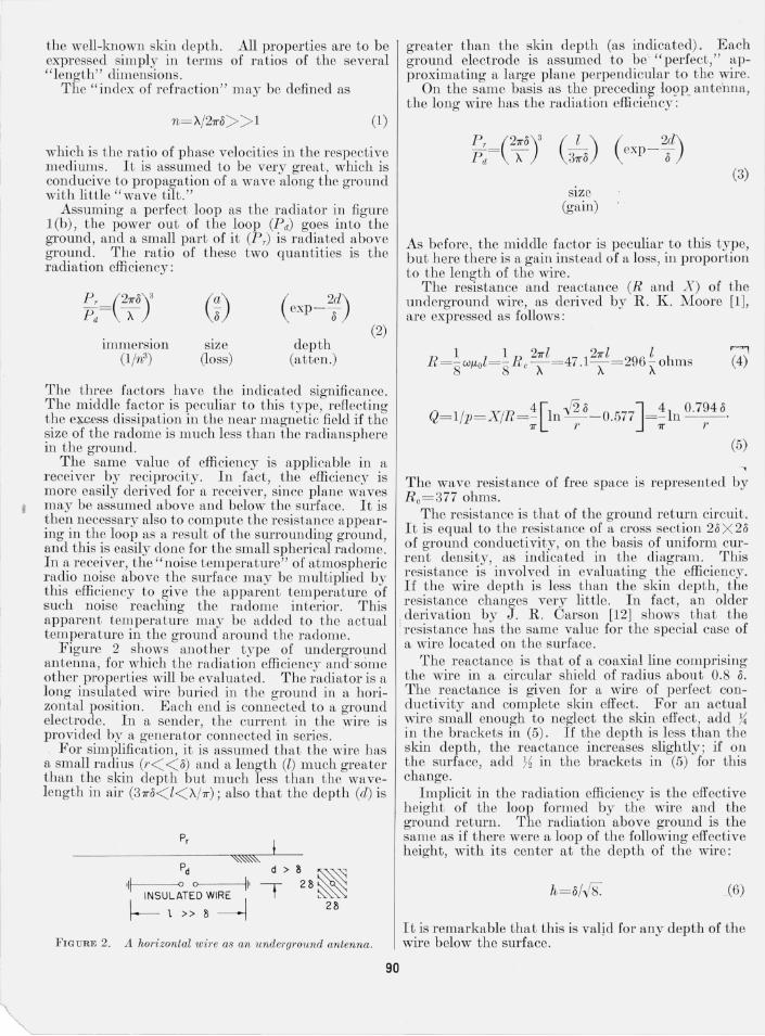
Figure 2 shows another type of underground antenna, for which the radiation efficiencv and; some other properties will be evaluated. The iadiator is a long insulated wire buried in the ground in a horizontal position. Each end is connected to a ground electrode. In a sender, the current in the wire is provided by a generator connected in series.
For simplification, it is assumed that the wire has a small radius (r < < 8) and a length (l) much greater than the skin depth but much less than the wavelength in air (3 7ro < l< 'A/7r) ; also that the depth (d) is
P,
~~" Pd d > 8 ~~~
.11 0 0 II' 2 8 ~~ INSULATED WIRE I t ~ f-- 1 » 1) ------j 2 I)
FIGURE 2. A horizontal wire as an underground antenna.
90
greater than the skin depth (as indicated). Each ground electrode is assumed to be" perfect," approximating a large plane perpendicular to the wire.
On the same basis as the preceding !09P_ ante'nna, the long wire has the radiation efficiency:
~: =e~oy C:8) ( exp - 28d) (3)
slze (gain)
As before, the middle factor is peculiar to this type, but here there is a gain instead of a loss, in proportion to the length of the wire.
The resistance and reactance (R and X) of the underground wire, as derived by R. K. Moore [1], are expressed as follows:
Q= l/p= X/R = 'i [In -f2 0 - 0.577J= 'i In 0.7948. 7r r 7r r
(5)
The wave resistance of free space is represented by R c = 377 ohms.
The resistance is that of the ground return circuit. It is equal to the resistance of a cross section 2o X 28 of ground conductivity, on the basis of uniform current density, as indicated in the diagram. This resistance is involved in evaluating the efficiency. If the wire depth is less than the skin depth, the resistance changes very little. In fact , an older
i derivation by J. R. Carson [12] shows that the . resistance has the same value for the special case of a wire located on the surface.
The reactance is that of a coaxial line comprising the wire in a circular shield of radius about 0.8 8. The reactance is given for a wire of perfect conductivity and complete skin effect. For an actual wire small enough to neglect the skin effect, add ?~ in the brackets in (5). If the depth is less than the skin depth, the reactance increases slightly; if on the surface, add ?f in the brackets in (5) for this change.
Implicit in the radiation efficiency is the effective height of the loop formed by the wire and the ground return. The radiation above ground is the same as if there were a loop of the following effective height, with its center at the depth of the wire:
h=8/-/8'. (6)
It is remarkable that this is valid for any depth of the wire below the surface.

An example of the long wire underground is described by the following dimensions and computed properties:
Frequcncy ________ ___ j = 1 Mc/s, wavelcngth __ __ _______ A= 300 m , ground conductivity _ _ u= O.Ol mho/m, skin depth ___________ 0= 5 m, depLh ________________ d= 1 m, length _________ ______ l= 100 m, radius _____________ __ r=3 mm, index of refraction_ _ _ _ n = 10 effective heighk ______ h= 1.8 m, resistance ___________ _ R = 99 ohms, reactance_ _ _ _ _ _ _ _ _ _ _ _ X = 900 ohms, power factoL ________ p= O.ll, radiation efficiency _P T/Pa= 0.00l4 = - 28.5 db.
In Lhis example, for each 1 kw of power into the ground, only 1.4 w will end up in useful radiation above the surface.
The efficiency can be increased by locating a number of wires (N) in parallel in a grid, and supplying all with equal currents to form a sort of "current sheet." 1£ the wires are spaced more than the skin depth (or more than twice the skin depth if near the surface) the efficiency is multiplied by the number (N) approximately.
Two practical problems have been ignored in the above. One is the power loss in the end connections. The other is the current variation along the wire.
The ground electrode for each end connection should have enough surface to reduce its resistance much below the irreducible value of the ground return (given above).
Some current variation fLlong the wire is caused by the voltage applied to the capacitance to ground through the in ulation. The voltage developed by the resistance is inevitable. However, the voltfLge developed by the reactance can be reduced by inserting series capacitors along the length. In the present case, for example, a capacitor of 50-ohms reactance (about ?~ R ) may be inserted at intervals of 50-ohms wire r eactance to tune out this reactance at one frequency. This would require 18 series capacitors in the wire.
The straight long wire does not have the highest efficiency possible for its length. A nalTOW loop of the same length, enelosed in a cylindrical radome, has greater efficiency by virtue of its wire return instead of a ground return. However, this loop
565004~GO--8 91
has a much smaller power factor, so it must be critically tuned and has a relatively narrow bandwidth.
These formulas for radiation efficiency and other properties are intended to indicate the behavior of certain types of underground (or underwater) antennas. They are expressed in simple terms, and they fit into the usual computations of terminal circuits and point-to-point transmission.
The earlier work of Carson [12) and Moore [1) has contributed much to this subject, as Inentioned in the text . The recent studi es have been Inade as an aid to practical designs being proposed by Developmental Engineering Corp.
References
[1] R. K. Moore, The t heory of radio communication between submerged submarin es, Corn ell Un iv ., thcsis (June 1951) .
[la] J . R. Wait, The m agnetic dipo le a ntcnn a immerscd in a conducting m cdium, Pl'oc. IRE 40, 1244 (HJ52) .
[2] H. A. Whecler , Radio wave propagation formu las, Hazeltine Rcpt. 1301W (May 11, 1(42). (Transmission formul a as a power rat io, interception a rea, rad ia ncircle.)
[3] I-I . A. Wheeler, U niversal skin-effect char t for conducting matcrials, E lectro nics 25, 152 (1952) . (Formulas a nd charL, in cluding land and water, all frcquencies.)
[4] I-I. A. Wheelcr, Fundamental li mitat ions of a small VLF anten na for submarin cs, IRE Trans. A 1'- 6, 123 (1958). (Coil in spherical radom e ubmerged in water, power in te rcept ion area, power factor.)
[5] I-I . A. Wheelcr, The spherical coil as an inducLor, shield or a ntenna, Proc . IRE 46, 1595 (1958). (Coil in spherica l radome submerged in water. )
[6] H . A. \Vheelcr, The rad ia nsphere arou nd a small antenna, Proc. IRE 47, 1325 (1959) .
[7] L. E. Rawls, A practical und erground transmitting ante nn a, topic presented bv Developmcntal Enginecring Corp. in mceting on J an . 26, 1960, at t he NBS, Boulder, Colo.
[8] C. R . BurrolVs, Radio propagation over p lanc earth- fi cld strength curves, Bcll Systcm T cch. J . 16, 45 (19:37). (Transmission formu la as a powcr ratio .)
19] I-I . T . Friis, A notc on a s imple transmiss ion formula, Proc. IRE 19, 254 (1946). (Transn"li ss ion formula as a power ratio in t erms of intc rcept ion a rea.)
[10] S. A. Schelkunoff a nd H . T . Friis, Antennas- Thcory and pract ice (John ·Wiley & Sons, In c., N ew York, N.Y., 1952). (Transmiss ion formu la as a power ratio, problems, pp. 300-1.)
[11] Ie. A. Norton , Transmission loss in radio propagationII, NBS T ech . Note 12 (Jun e 195!J). (Power ratios.)
[12] J . R . Carson , Wave propagation in ovcrhead wires with grou nd rcturn, Bell System T ech. J . 5, 539 (1926) .
(Paper 65DI-I06)
)