Embed Size (px)
Citation preview

ALOHA
• Possibly first modern data network- Deployed in 1970 (before Ethernet)
- 9,600 Baud
• Designed to communicate across Hawaiian islands- Hub at ALOHANET headquarters
- Many other sites on islands
• Used two radio frequencies- One frequence for hub to broadcast messages
- Another (shared) frequency for other sites to transmit

ALOHA transmission
• Send all packets to hub- Hub re-broadcasts all packets it receives
• Listen after sending packet- If you hear your packet broadcast, transmission OK
- Otherwise, assume a collision
• If collision, retransmit after random delay

Multiple access
• Multiple access was revolutionary at the time- Now seems like common wisdom
• Previous systems partitioned channels- TDMA, FDMA, etc.
• ALOHA optimized case of few senders- Can potentially transmit immediately—much lower delay
- With TDMA, wait your turn while channel unused
- But have to deal with collisions (which lower throughput)

Throughput
• Initial ALOHANET had ∼18% throughput- ∼81% of bandwidth wasted by collisions
- Unlike Ethernet, large distance & no collision detection
• Improved with slotted ALOHA- Divide time into equal sized slots
- Only transmit at beginning of a slot
- If collision, transmit on future slots with probability p
• Slotted ALOHA raised utilization by factor of two- Avoided many partial collisions

802.11
• Modern standard for wireless networks- 11 Mbps (newer standards allow 54 Mbps)
- Widely deployed (around NYU, in people’s homes)
- Can often just pick up someone’s signal to get on net(Not recommended because it’s possibly illegal)
• Designed for smaller spaces (250m range)- Spread spectrum with frequency hopping
- Operates over 79 1 Mhz-wide slots around 2.4 GHz
- Makes it harder to jam the signal (inadvertently)
• Can also use direct sequence, or IR (10m)
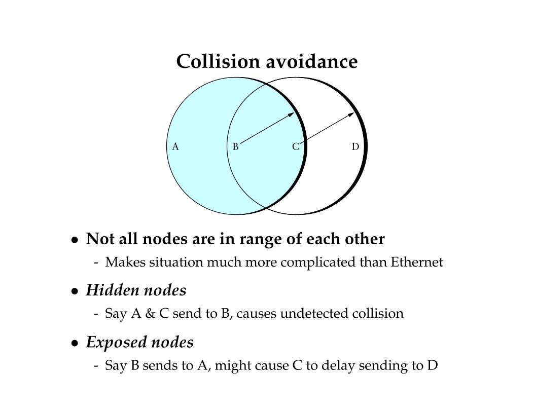
Collision avoidance
A B C D
• Not all nodes are in range of each other- Makes situation much more complicated than Ethernet
• Hidden nodes- Say A & C send to B, causes undetected collision
• Exposed nodes- Say B sends to A, might cause C to delay sending to D

MACA(W)
• Multiple Access with Collision Avoidance- Sender sends RTS (request to send) pkt, w. length
- Receiver replies w. CTS (clear to send) pkt, echoing length
- If you see CTS packet, don’t transmit (you are near receiver)
- If you see RTS but not CTS, okay to transmit
• MACA for Wireless LANS (MACAW) adds ACK- Receiver sends ACK for packet
- All nodes must wait for ACK before sending a packet
• Two RTS packets may collide- Detect by timing out CTS
- Backoff similarly to Ethernet

Distribution system
B
H
A
F
G
D
AP-2
AP-3AP-1
C E
Distribution system
• 802.11 usually operates in infrastructure mode- Access points—non-mobile nodes on wired network
• Distribution System connects Access Points- Example: A sends to E, AP-1 gets pkt, sends it to AP-3
- Typically hook to Ethernet & use learning bridge technique
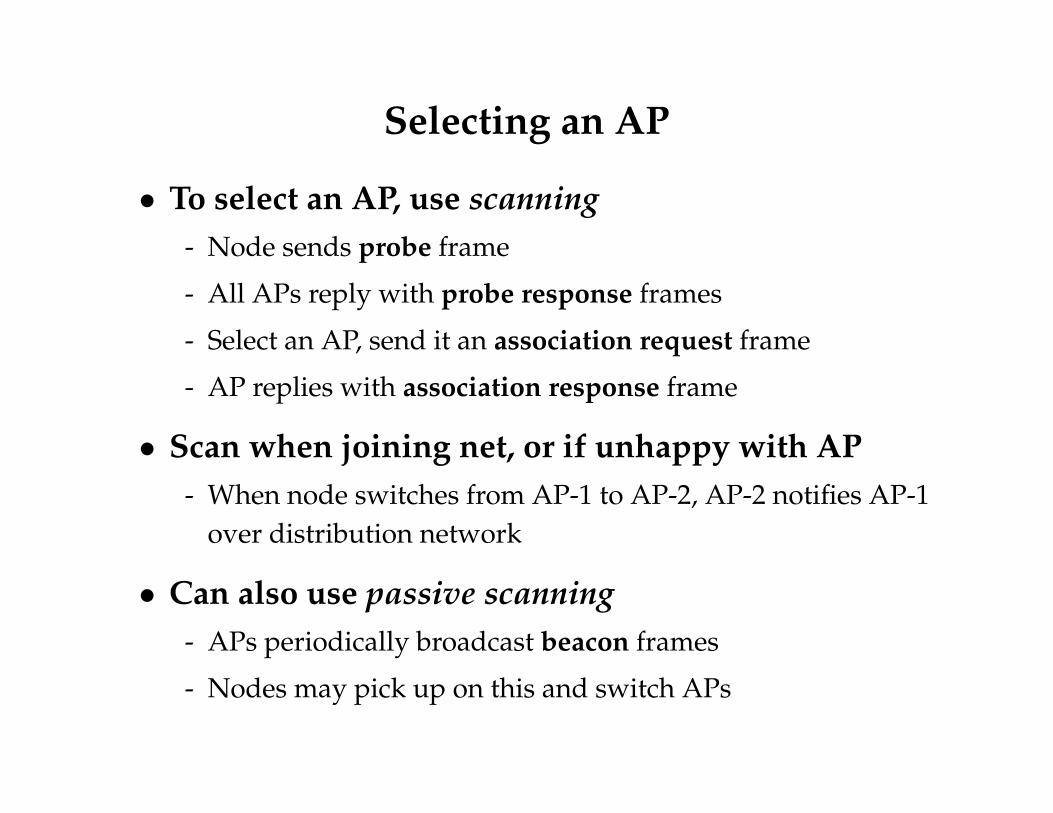
Selecting an AP
• To select an AP, use scanning- Node sends probe frame
- All APs reply with probe response frames
- Select an AP, send it an association request frame
- AP replies with association response frame
• Scan when joining net, or if unhappy with AP- When node switches from AP-1 to AP-2, AP-2 notifies AP-1
over distribution network
• Can also use passive scanning- APs periodically broadcast beacon frames
- Nodes may pick up on this and switch APs

802.11 frame format
Addr4 PayloadSeqCtrlAddr3Addr2Addr1 CRC
0–18,4964816 32484848
Duration
16
Control
16
• Control field contains 6-bit type field- Types include data, RTS, CTS, scanning
• Two other bits in control: ToDS & FromDS- DS = Distribution System – when packet goes via DS
• Notice 4 address fields- When FromDS/ToDS both set, specifies intermediary hops
- Addr1 – ultimate destination, Addr4 – original source
- Addr2 – immediate sender, Addr3 – intermediatedestination

Ad hoc networks
• Sometimes want to deploy wireless network w/oinfrastructure
- Use nodes to forward data to each other
- But don’t know anything about node locations a priori
• These are called ad hoc networks
• Examples:- Emergency workers deployed to disaster area
- Construction sites, mining equipment
- Sensor networks, Rooftop networks

The routing problem
R
S
D
• Find end-to-end path (route) from S to D
- Each router must find an adequate next hop
• Topology may be very dynamic in ad hoc networks

Existing routing algorithms
• Can we just use DV or LS routing protocols?
• Problems:- DV & LS both send maintenance packets – uses bandwidth
and also maybe battery power (important for ad hoc nets)
- Wireless networks have many more redundant links(increases size of routing updates, CPU utilization)
- Asymmetry – host A may hear broadcast from B, but not beable to send to B
- Loops – simple DV/LS protocols can cause loops givenincorrect information. More likely in dynamic environment.

DSR
• Dynamic Source Routing- Each packet contains source route—hops to go through
- Routes determined on-the-fly, heavily cached
• Route discovery – to find a route to target D
- Packet contains a route record with path from sender
- If a node has the route, prepends route record and replieswith route reply
- As special case, if node is target this works, too
- Otherwise, nodes re-broadcast the route request
- Append own address to route record before re-broadcasting

DSR continued
• Avoid re-broadcasting same packets- Each route request contains a request id
- Cache recently seen 〈initiator-id, request-id〉 pairs
- Discard already seen 〈initiator-id, request-id〉 pairs
- Also discard if your route already appears in route record
• When sending route reply packet- If links bi-directional, can reverse route
- Else, must discover own route to source (if none cached)
- Can piggyback route reply onto route request packet

Route maintenance
• May have many broken links when node move- Expensive – takes time to timeout packet to bad destination
- But proactive notification would be expensive, too
• Report broken links with route error packets- Must truncate all routes that use the broken link
• Requires ACKs to know if next hop got packet- Okay for MACAW
- w/o ACKs, can use passive acknowledgement by listeningfor re-broadcast

Optimizations
• Intermediary hops augment their caches- If you reach D via A → B → C → D, have route for C
- When B forwards packet A → D, learns routes to C and D
- Can also use promiscuous mode to learn routes from others
• Limiting collisions of route reply packets- Delay d = H(h − 1 + r), where h is number of hops in
route, r is random number 0 ≤ r ≤ 1
- Listen promiscuously for other route replies during delay
- Favors shorter routes, avoids collisions, reduces traffic
• Route request has max # times to re-broadcast- Request 1 hop first, then ∞

More optimizations• Piggybacking on route discoveries
- Small packets (e.g., TCP SYN) can be piggybacked
- But must handle cached routes differently—reply withcached route and forward packet to destination
• Discovering short routes- Suppose using routes B → C → D and D → C → B
- If B moves close to D, would like to send directly
- Discover this special case using promiscuous mode
• Eavesdrop on route error packets
• Cache bad links- Because of asymmetry, might receive cached routes
containing a link just purged from your routing table

Limitations of DSR
• On-demand routing adds latency
• Each node must keep lots of state- Every route the node employs
- Possibly other routes overheard through eavesdropping
• Extra overhead for routing packets
• What is solution proposed by GPSR?

GPSR
• Use geography to forward packets- Every node can know its exact location w. GPS receiver
- E.g., all new cell phones have GPS built in for E911
• Assume some way to look up nodes’ locations- E.g., There is some mapping from IP address to location
- There are P2P ways of doing this (perhaps discuss later)
• Forward pkts using location to minimize state
• Other assumptions- Bi-directional communication (as with 802.11 RTS/CTS)
- All nodes roughly at same altitude
- No weird obstacles to transmission

Greedy forwarding
Nodes learn immediate neighbors’ positions throughbeacons/piggybacking on data packets
Locally optimal, greedy forwarding choice at a node:Forward to the neighbor geographically closest to the destination
y
x
D
Are we done?

Greedy forwarding failure
Greedy forwarding not always possible! Consider:
w
v z
x
y
D

VoidsWhen the intersection of a node’s circular radio range and the circleabout the destination on which the node sits is empty of nodes,greedy forwarding is impossible
Such a region is a void:
D
v z
w
x
y
void

Node Density and Voids
0
0.1
0.2
0.3
0.4
0.5
0.6
0.7
0.8
0.9
1
1.1
0 50 100 150 200 250 300
Fra
ctio
n o
f p
ath
s
Number of nodes
Existing and Found Paths, 3000 m x 600 m Region
Fraction existing pathsFraction paths found by greedy
Probability of empty void region increases as nodes become sparserUnacceptable not eventually to find valid routes

Void Traversal: The Right-Hand RuleWell-known graph traversal: right-hand rule:
When arriving at x from y, move to the next vertexcounterclockwise about x from y
y
3.1.
2.x z
Traverses interior faces in clockwise edge order; exterior faces incounterclockwise edge order
So use RHR when greedy fails. Are we done?

Planar vs. Non-Planar Graphs
The right-hand rule may not tour enclosed faces on graphs withedges that cross (non-planar graphs)
x
u
vw
z
5. 1.
2.3.
4.
3.4.
Seek a distributed algorithm that removes crossing edges withoutpartitioning the network, using only neighbors’ positions as input

Planarized Graphs
Relative Neighborhood Graph (RNG) [Toussaint, ’80] and GabrielGraph (GG) [Gabriel, ’69] are long-known planar graphs
Assume an edge exists between any pair of nodes separated by lessthan a threshold distance (i.e., the nominal radio range)
RNG and GG can be constructed using only neighbors’ positions,and can be shown not to partition the network!
u v
w
RNG
u v
w
GG

Planarized Graphs: Example
200 nodes, placed uniformly at random on a 2000-by-2000-meterregion; radio range 250 meters
Full Network GG Subset RNG Subset

Full Greedy Perimeter Stateless Routing
All packets begin in greedy mode
Upon greedy failure, node marks its current location in packet, andmarks packet in perimeter mode
Perimeter mode packets follow simple planar graph traversal:
Forward along successively closer faces by right-handrule, until reaching destination, or node closer to it thanperimeter mode entry point
Return packets to greedy mode when they reach a node closer thantheir perimeter mode entry point

Perimeter Mode Forwarding Example
D
xTraverse face closer to D along xD by right-hand rule, untilreaching the edge that crosses xD
Repeat with the next closer face along xD, etc.
Record first edge on face to detect disconnection

GPSR packet header
Field Function
D Destination Location
Lp Location Packet Entered Perimeter Mode
Lf Point on xV Packet Entered Current Face
e0 First Edge Traversed on Current Face
M Packet Mode: Greedy or Perimeter