Embed Size (px)
Citation preview
Used Concrete Recycled as Aggregate for New Concrete
A bachelor thesis
Mats D. Skevik Hole
10.06.2013
2
- Titulación: Grado en Arquitectura Técnica - Estudiante: Mats D. Skevik HOLE - Tutor: Enrique DAVID LLÁCER - Título del proyecto: Used Concrete Recycled as Aggregate for New Concrete - Fecha presentación: 14/06/2013 - Modalidad: Intercambio
3
Table of contents
Abstract................................................................................................................................................... 4
Recycled Concrete Aggregates (RCA) .............................................................................................. 5
The recycling process .......................................................................................................................... 5
The recent use of recycled concrete .................................................................................................. 5
The importance of recycling concrete ................................................................................................ 6
The Equivalent Mortar Volume (EMV)-method ................................................................................ 7
Research in the field of RCA ............................................................................................................... 8
Compressive strength ...................................................................................................................... 8
Shear strength ................................................................................................................................. 10
Tensile strength ............................................................................................................................... 13
Modulus of elasticity ....................................................................................................................... 14
Durability........................................................................................................................................... 15
Drying shrinkage and creep .......................................................................................................... 21
RCA concrete in different countries ................................................................................................. 22
Contribution .......................................................................................................................................... 25
How the reduction of the compressive strength affects the capacity of a beam ....................... 25
Excel worksheet .................................................................................................................................. 27
Possibilities for using RCA concrete in non structural construction materials. .......................... 31
Concrete sandwich panels ............................................................................................................ 31
Table of suggested possibilities for RCA concrete in concrete sandwich panels ................. 37
Concrete Sound Walls ................................................................................................................... 38
Table of suggested possibilities of using RCA concrete in concrete sound walls ................ 41
Architectural precast concrete panels .......................................................................................... 42
Table of suggested possibilities of using RCA concrete in precast curtain walls ................. 46
Stonework ........................................................................................................................................ 47
Table of possibility for using RCA concrete in stonework......................................................... 53
Concrete Pavements ...................................................................................................................... 54
Table of suggested possibilities for utilization of RCA concrete in concrete pavements ..... 60
Conclusion ........................................................................................................................................... 61
Acknowledgement ............................................................................................................................... 62
List of annexes .................................................................................................................................... 62
References ........................................................................................................................................... 63
4
Abstract
This dissertation has investigated recycled concrete aggregates in bound form. It has given a
general overview of what RCA is and the importance of utilizing it. A presentation of the
latest research conducted on the material with a special focus on the mechanical properties
is given. The new concrete mixture proportioning method called the Equivalent Mortar
Volume method is being presented and an Excel worksheet for using the new method is
created. This worksheet is more like an example than a program for concrete proportioning.
A short investigation of how a reduction of compressive strength reduces the resistance of a
beam is also conducted. The reduction of compressive strength is calculated after a
proposed equation which takes the amount of RCA into account. At last a study of non
structural possibilities for RCA has been carried out.
5
Recycled Concrete Aggregates (RCA)
Due to the vast amount of concrete being produced and the huge amount of demolition
waste from old concrete structures, recycling concrete has become a necessity. New
standards, design criteria and wear and tear forces forward the demolition of concrete. And
to save space at landfills and disposal dumps it is important to take care of this waste in an
environmentally friendly way. Recycled concrete aggregates are simply crushed old concrete
elements, and it can be used in various applications.
The recycling process
At first, in the recycling process it is important to control the quality of the concrete which is
going to be recycled. The next step is the crushing, and it is several crushing methods. Most
common is the jaw crusher. But there are also cone crushers and large impact crushers.
Sometimes the concrete needs to be crushed more than ones, to get a satisfying
consistence. After crushing, the concrete is screened. A scalp screen removes dirt and
foreign elements. A fine harp deck removes the smaller elements, from the larger. For further
cleaning of the recycled concrete, methods like water flotation, hand picking, air and
electromagnetic separation is used. These methods are described by the construction
materials recycling organization (1).
Also wet concrete from precast concrete production cause a waste disposal problem. This is
the redundant wet concrete, which is not used for anything. Each year somewhere between
7 and 10 billion cubic of concrete is produced, and actually 50 million cubic is not used on the
construction site. This problem has the cement chemical manufacturer Mapei found a
solution for. The product is called Re-Con Zero, and is short for Returned Concrete with Zero
Impact. When the wet redundant concrete is mixed with Re-Con Zero new aggregates can
be made. According to Mapei this aggregates has the same properties as natural aggregates
(2).
The recent use of recycled concrete
At this moment, concrete made with RCA is not commonly used for structural purposes.
Their poor structural properties can be the ultimate reason. Most studies have shown that an
increase in the amount of RCA leads to a decreasing performance of the concrete. Problems
with high water absorption and low E-modulus are suggested to be the main problems.
The range of water absorption in RCA used as coarse aggregate is 3.5 % to 9.2%, while
water absorption for natural aggregate concrete (NAC) is 0.5% to 5% (3).This can lead into
micro cracks in the cement paste and a lower workability of the concrete. The quality of the
6
origin concrete is also difficult to control. In a Spanish article (4) it is mentioned that
comparing studies about RAC can be difficult because of the uncertainty of the origin of the
concrete that has been recycled. RCA technology is not developed to the point were it is a
well known material. Regulations and codes are not common for RCA. And this makes it
difficult to use it in building designs.
Up to now RCA is mostly used in non structural applications. In unbound form, it is used as
subbase for slabs on ground, gravel for roads and in under concrete pavements. There are
examples of using it in buildings, e.g. the Shanghai ecological building (5). And in the
enterprise park at Stapleton in Denver, Colorado (6). In Singapore, RCA concrete has been
utilized in several projects. One of these projects is the Wop Hup Building. In this office
building 30% RCA and 30% washed copper slag is used in its superstructure (7).
In an article from 2002 it can be read that RCA concrete is prohibited because of its
significant impact on drying shrinkage and creep (8). This will be presented in a deeper way
later in this paper. However it should be noted that the state of the art regarding RCA
concrete is possibly the EMV method. This method will also be explained in the following.
The point is that it can contribute to a higher recycling rate of waste concrete. And therefore it
will affect the use of RCA in the future.
The importance of recycling concrete
In many areas, especially around some of the larger cities in the world, sources of natural
virgin aggregates like sand and gravel has been depleted (9). This has become an
environmental problem, because aggregates are now transported over longer distances. So
preserving natural resources by using RCA is environmentally desirable. Because the source
of RCA is usually in the urban areas, and this gives a possibility of using resources from the
city.
Many of the old concrete structures in older buildings do not fulfill the requirements of the
current standards. These structures must be taken down. And that is why currently a huge
amount of demolition wastes containing concrete now has become a problem. In 2012 is was
produced 1 ton of concrete per human being in the world, and with a world population of
approximately 7 billion people the answer gives its self (3). The amount of demolition waste
concrete will be higher in the future. This is one reason for creating technology which can
handle this problem.
The production of cement is one of the largest contributors to CO2 emissions, when looking at
the production of construction materials. The global production of cement was in 2010 over
7
3.3 billion tons, and it stood for about 5% of the anthropogenic CO2 emissions (10). To
produce cement a process named calcination is necessary. In this process limestone is
heated and chap into calcium oxide and CO2. This is an inevitable process for making
cement and it is the opposite of the carbonating process, which lowers the steel protecting
alkaline level in concrete.
The Equivalent Mortar Volume (EMV)-method
When mixing concrete with RCA, it is necessary to take into account the residual mortar in
the old concrete. If this is not considered, the total mortar volume in the RCA concrete
becomes larger than the mortar volume in natural aggregate concrete (NAC) mixtures. This
higher mortar volume is believed to be the reason for the lower performance in RCA
concrete. By using the EMV method, the cement amount is reduced. As a consequence
becomes the amount of new fresh mortar reduced. And the total mortar volume in RCA
concrete becomes equivalent to the NAC. Reduction of cement used in concrete also leads
to a reduction in CO2 emissions. And using EMV method will therefore reduce CO2
emissions as well as preserve natural resources by using recycled concrete.
8
Research in the field of RCA
Compressive strength
A Chinese study by Li et al. has tested the compressive strength of RCA concrete (5). They
tested both the concentric and the eccentric loading capacity. In both cases they found
similar failure mechanisms for RCA concrete and NAC. This is also mentioned in another
article (11). Similar load-deformation curve for concentric load, and a neglecting influence on
the N-M diagram for eccentric loading, was also discovered (5).
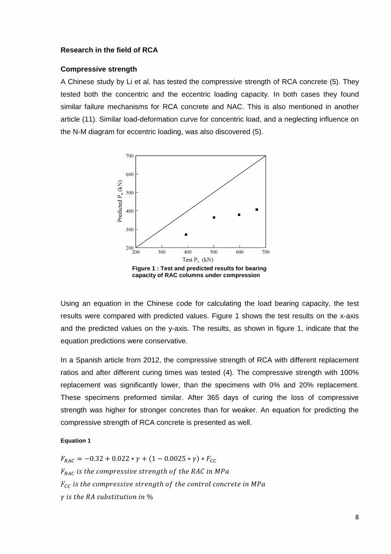
Using an equation in the Chinese code for calculating the load bearing capacity, the test
results were compared with predicted values. Figure 1 shows the test results on the x-axis
and the predicted values on the y-axis. The results, as shown in figure 1, indicate that the
equation predictions were conservative.
In a Spanish article from 2012, the compressive strength of RCA with different replacement
ratios and after different curing times was tested (4). The compressive strength with 100%
replacement was significantly lower, than the specimens with 0% and 20% replacement.
These specimens preformed similar. After 365 days of curing the loss of compressive
strength was higher for stronger concretes than for weaker. An equation for predicting the
compressive strength of RCA concrete is presented as well.
Equation 1
Figure 1 : Test and predicted results for bearing capacity of RAC columns under compression
9
From equation 1 it is possible to find a compressive strength for the control concrete where
the substitution of RA does not have any effect. This value is 8.8 MPa and is a theoretical
value.
In 2012 another study which compares predicted values of the compressive strength with
test results was executed (11).The purpose of this study was to investigate if reinforced
concrete columns made with RCA fulfill the American Concrete Institute (ACI) design
strength criteria. The equation for maximum nominal axial load capacity in ACI is:
Equation 2
When using this formula and compeering it with the test results, all of the specimens
maximum nominal axial load capacity were predicted lower than the test results. So this
indicates that reinforced concrete columns made out of RCA are strong enough to fulfill the
ACI design criteria for maximum nominal axial load capacity.
An article by Marie et al. investigates the properties of RAC after it has been recycled one
more time (3). Replacing 20% of the natural aggregate each time it is recycled. The
compressive strength of the RCA concrete decreased with 20 %, while the recycled-RCA
concrete decreased only 12 %. Both compared with NAC. It is believed that the reduction in
the residual mortar, when the concrete is recycled one more time, makes the recycled RCA
concrete perform better than the RCA concrete.
This leads to the new method for proportioning concrete, the Equivalent Mortar Volume
(EMV)-method. An investigation on this new method was done in Spain (12). They replaced
20% of the NA with RCA and used the EMV-method for proportioning. Regarding the
compressive strength the observed specimens presented no major differences. They
concluded that the ACI mixes made by the EMV method, with Spanish aggregates, gave
similar compressive strength for both RCA concrete and NAC.
In reviewing the research about RCA concrete, it can be stated that when the replacement
ratio is high and the RCA concrete is proportioned after conventional methods, the loss of
compressive strength likely to occur. The reduction in compressive strength capacity can be
larger for stronger concretes. However if the replacement ratio is low and the residual mortar
is taken into account, RCA concrete can be made with acceptable compressive strength.
10
Shear strength
It has been recently reported a negative effect on the shear strength (5). A decrease of 10%
with 50% RCA and a 17% decrease in strength with 100% RCA. The research was only
carried out over beams. Another study found a decrease in shear strength of 30% when the
amount of RCA increased from 0% to 100%. These reductions make it impossible to use the
equations for normal beams in ACI 1318, EC2 and the Chinese code GB50010 to calculate
the shear strength. It is suggested a reduction factor which consider the amount of RCA. This
can be used in the Chinese code for normal beams.
Equation 3
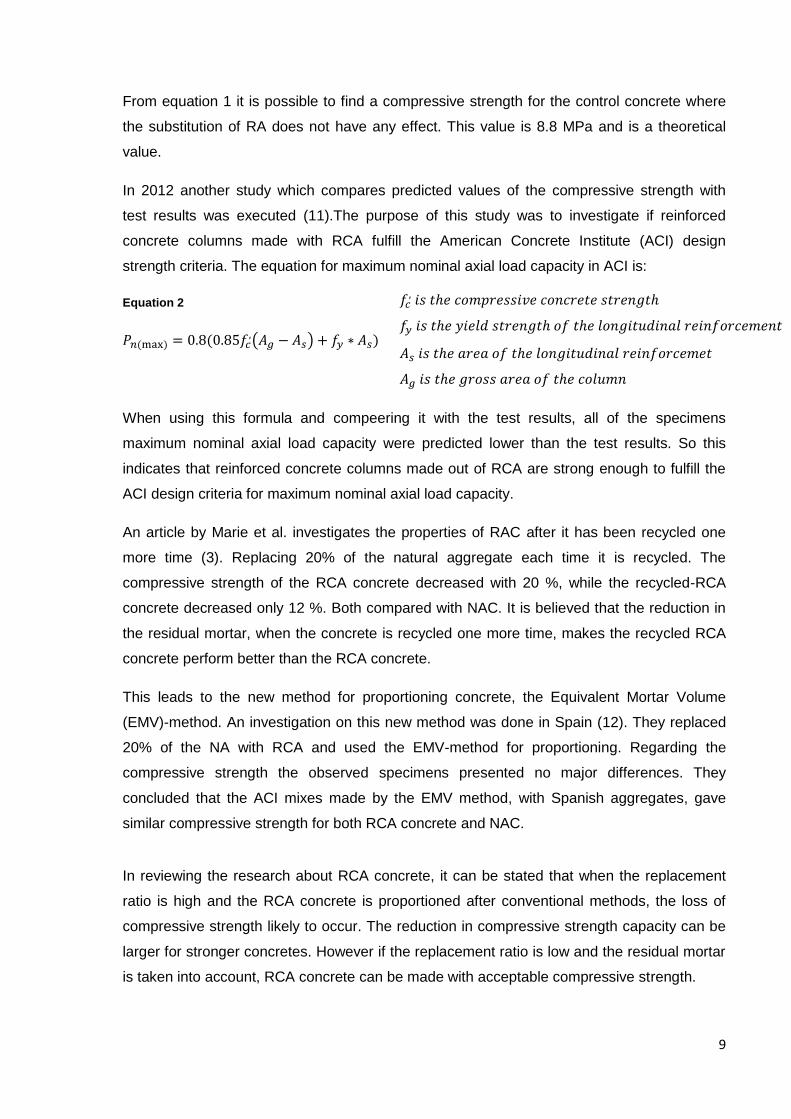
But in the Chinese technical code for RAC, SCSS 2007 an equation is given for calculating
the shear strength (5). This is equation 4.
Equation 4
Figure 2 shows the comparison of the test and predicted results by using equation 4.
Figure 2 - Compression of the test and predicted results for shear strength of RAC beams
11
A Swiss study that compares different formulas form different codes is done in 2012 (13).
This study examined the effect of shear resistance in unreinforced concrete slabs. All the
slabs had the same geometry, so this investigation realizes that the results are limited to this
geometry.
It was observed similar crack distributions in the NC and the RCA slabs. And the increase of
RCA did not affect the resistance significantly. Previous studies of beams have reported
different crack distributions and a decrease of resistance when the RCA increases.
When comparing different formulas from different codes the results showed a good
correlation between test results and equations form EC2 and CSC. CSC corresponds to
“critical shear crack” theory, and it is the basis for the Swiss code. In this code the shear
resistance is calculated by using a reduction factor, as can be seen in equation 5 and 6.
Equation 5 - Shear resistance from CSC
Equation 6 - Reduction factor from CSC
Equation 7 - Strain in a critical section at a critical depth
The article concludes that the shear in RCA slabs, with the tested geometry, could be
predicted by existing equations (13).
An article which is presented by G. Fathifazl et al. has tested different sizes and its influence
on shear (14). Other test parameters are shear span to depth ratio, the source of RCA and
coarse aggregate type. When proportioning concrete mixes they have used the EMV method
on some of the samples and compared this with regular concrete proportion mixes. And they
.
12
have found that it is not necessary to change the formulas for shear prediction in the ACI,
and the Canadian CSA codes for beams with RCA as long as the EMV method is used.
In the article by G. Fathifazl et al. (14) investigations have found the ACI code equation
(11.3) overestimates the Shear strength. But the author did not find this effect. When results
of the equations were compared with all the test results it was clear that the equation
predicted lower values than the test results. It is believed in the article that the different
results comes from the different proportioning method used. The previous studies mentioned
in Fathifazl et al. article used conventional proportioning method when they prepared the
RAC concrete. In the new study the EMV method were used, and therefore a concrete with
better properties was made.
The shear span to depth ratio was tested in this article with different values to discuss how it
affected the shear strength (14). It was found that when the a/d ratio decreases, the
calculated shear strength generally becomes more conservative. Almost all of the theories
gave conservative predictions when varying the a/d. Some overestimated the resistance
when the a/d ratio became larger than 4.
It is also believed that the beam size has an influence on the shear strength of concrete. And
the investigation revealed that when increasing the beam size, the equations gave less
conservative predictions. Some equations eventually overestimated the shear strength in the
RCA beams. But the codes which the article found to be useful for calculating shear strength
of RCA beams were ACI 318, CSA A23.3 and EHE. This was regardless of shear span to
depth ratio, beam size and RCA source. This is assuming the RCA concrete are made after
the EMV method for proportioning the concrete mix.
To make a short summary on shear resistance of RCA elements some highlights is given:
ACI, EC2 and GB 50010 may not be applicable for shear calculations. The Chinese code for
RCA concrete can possibly be used (5). EC2 and CSC theory give conservative predictions
on shear resistance of unreinforced concrete slabs. And slabs performed better than beams
(13). Codes like ACI 318, CSA A23.3 and EHE can be applied for shear calculations if the
EMV method is used (14).
13
Tensile strength
Research has shown that the tensile strength in concrete depends on micro cracks in the
cement paste (13). And on the interfacial transition zone between the cement paste and the
aggregates with grain size larger than 4 mm. There are also other factors that play a role for
the tensile strength of concrete. But when looking at RCA concrete these two reported
effects are crucial. This is because both of these are connected with the water absorption of
the concrete, and in RCA concrete the water absorption is much higher than in regular
concrete.
C. Thomas et al. (4) investigated the tensile splitting strength of RCA concrete. The tensile
splitting strength decreases with the amount of RCA. For 100% RCA the tensile splitting
strength decreased with 20%. The investigation compares the results with previous articles.
Those existing articles stated a reduction between 21% and 35%.
Both the splitting and the flexural tensile strength were tested in the article by I. Marie (3). A
replacement of 20 % gave a decrease of 10 % compared with natural aggregate concrete.
When recycling the RCA concrete again and adding 80% natural aggregate the decrease
was only 5% compared with NAC. The article explains this with a reduction of residual mortar
in the second time the concrete is recycled.
14
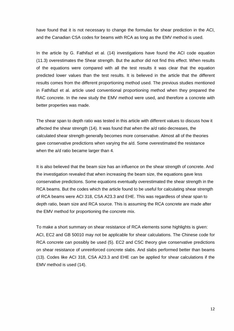
Modulus of elasticity
Because of the high residual mortar content in conventional RAC mixes, the modulus of
elasticity always seems to be lower (14). It can also be established that the RCA amount has
a more important influence on the elasticity modulus, than on the compressive strength (4).
But not only has the amount of RCA had an effect on the modulus of elasticity, the water
cement ration played an important role as well. It can be seen in figure 3 that the modulus of
elasticity decreases with the increasing of the water/cement ratio. We can also see the big
difference between the RAC with 100% replacement and the NAC.
Another study also found a reduction on the elasticity modulus (13). With a 100%
replacement of natural aggregates with recycled concrete the loss of the E-modulus was
about 16%. This is in fact about the same as in figure 3. Both these articles used
conventional proportion methods and did not take into account the residual mortar in the
RCA.
C. Jiménez et al. (12) finally identifies the process in establishing the modulus of elasticity
using the EMV method. With only a few exceptions the EMV concrete mixes gave a higher e-
modulus than conventional concrete mixes. It is recommend a replacement ratio of 20 % for
RCA and the use of the EMV method. With this amount of replacement it was not any
significant differences observed in the value of the modulus of elasticity.
Figure 3 - Modulus of elasticity versus w/c ratio

15
Durability
One of the most crucial factors for concrete is the durability. Concrete is known to be a
durable material, but this is only if the concrete is properly produced. So adding RCA into
concrete can be a problem, because of the residual mortar volume.
Figure 4 - Relative density vs. w/c ratio of different degrees of substitutions after 28 days (a), 180 days (b)
and 365 days (c)
C. Thomas et al. studied the durability of the RCA concrete (4). The investigation tested
concrete with different RCA replacements, w/c ratios, accelerated carbonation and gas
permeability. The most important findings were that for smaller w/c ratios the reduction of
durability is less than for larger w/c ratios. In order to avoid risks, study suggested stricter
regulations for RCA concrete in carbonation environments.
Figure 4 shows how the different amount of RCA affects the relative density. With 100%
substitution the concrete has a smaller value of relative density, than the ones with a less
amount of replacement. And a high w/c ratio makes the relative density smaller. This is not
only reported in RCA concrete. At figure 4 it can be observed that the w/c ratio have a
significant impact on the concrete with 0% RCA as well.
Throughout all reviewed scientific literature, the water absorption is one for the most
problematic factors affecting concrete manufactured form RCA. One of the reasons is the
origin and quality of the RCA. It is reported in (4) that RCA concrete requires more water for
the same workability as regular concrete and Schubert et al. (13) considered that whenever
the water absorption gets too big, micro cracks in the cement paste can occur. Therefore by
considering the RCA’s impact on the effective w/c ratio, the effect on the durability is also
considered. Figure 5 is from article (4), and shows the absorption coefficient after 28 days
(a), 180 days (b) and 365 days (c) with different w/c ratios. It is shown that the absorption
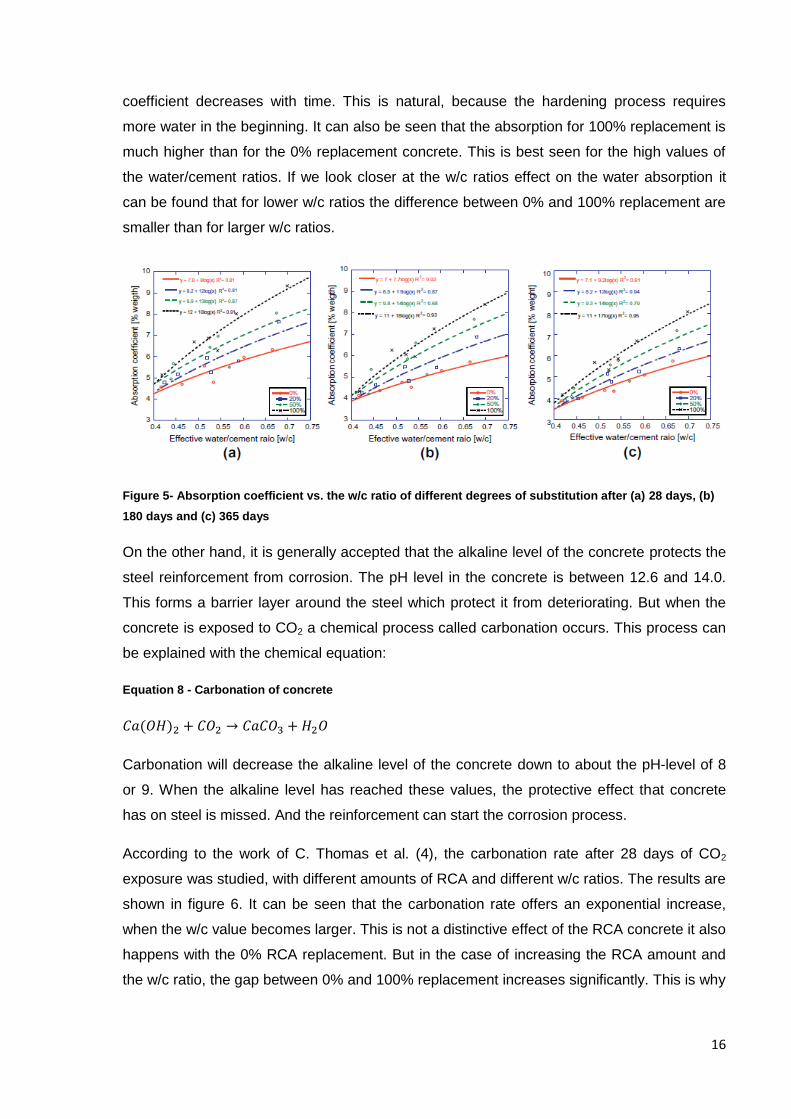
16
coefficient decreases with time. This is natural, because the hardening process requires
more water in the beginning. It can also be seen that the absorption for 100% replacement is
much higher than for the 0% replacement concrete. This is best seen for the high values of
the water/cement ratios. If we look closer at the w/c ratios effect on the water absorption it
can be found that for lower w/c ratios the difference between 0% and 100% replacement are
smaller than for larger w/c ratios.
Figure 5- Absorption coefficient vs. the w/c ratio of different degrees of substitution after (a) 28 days, (b)
180 days and (c) 365 days
On the other hand, it is generally accepted that the alkaline level of the concrete protects the
steel reinforcement from corrosion. The pH level in the concrete is between 12.6 and 14.0.
This forms a barrier layer around the steel which protect it from deteriorating. But when the
concrete is exposed to CO2 a chemical process called carbonation occurs. This process can
be explained with the chemical equation:
Equation 8 - Carbonation of concrete
Carbonation will decrease the alkaline level of the concrete down to about the pH-level of 8
or 9. When the alkaline level has reached these values, the protective effect that concrete
has on steel is missed. And the reinforcement can start the corrosion process.
According to the work of C. Thomas et al. (4), the carbonation rate after 28 days of CO2
exposure was studied, with different amounts of RCA and different w/c ratios. The results are
shown in figure 6. It can be seen that the carbonation rate offers an exponential increase,
when the w/c value becomes larger. This is not a distinctive effect of the RCA concrete it also
happens with the 0% RCA replacement. But in the case of increasing the RCA amount and
the w/c ratio, the gap between 0% and 100% replacement increases significantly. This is why
17
the article (4) suggests more restrictive mixtures for RCA in carbonation aggressive
environments.
Another important property for studying the durability of concrete is its oxygen permeability.
C. Thomas et al. reported that it is the amount of RCA that have an effect on the effective w/c
ratio (4). This is because of the high water absorption of the RCA. Therefore the oxygen
permeability has been 15% lower for RCA mixes than for regular mixes.
In 2009 a study on durability of concrete with RCA was conducted (15). The target was to
see how RCA concrete, mixed with the EMV method, performed compared with conventional
mixed RCA concrete. This investigation was focused on durability properties which are
crucial for concrete in northern climates. The tested factors are freeze-thaw, chloride
penetration and carbonation resistance. Results proved that the RCA concrete, mixed with
the EMV-method, had comparable durability parameters to concrete mixed with conventional
methods.
In addition, the paper (15), studied the material characteristics of the aggregates. Properties
analyzed were absorption capacity, specific gravity, porosity and residual mortar content
(RMC). The RMC is the percentage of residual mortar weight of the total RCA weight. Table
1 gives us the characterization of the aggregates.
Figure 6 - Carbonation rate as a function of the w/c ratio
18
Aggregate Porosity (%) Absorption
capacity (%)
Specific gravity RMC (%)
Bulk SSD Apparent
RCA-MO 12,3 5,4 2,31 2,42 2,64 41
RCA-VA 8,1 3,3 2,42 2,50 2,64 23
Limestone 0,9 0,34 2,70 2,71 2,73 0
River gravel 2,4 0,89 2,72 2,74 2,79 0
River sand - 0,54 2,70 2,72 2,76 -
This last mentioned research paper investigated how the additions of fly ash and blast
furnace slag (bfs) affected the durability (15). At the same time they tried to hold the
compressive strength and the w/c ratio constant. Compressive strength varied from 35 to 40
MPa and the w/c ratio was 0.45. The target air volume was 6%. All the test specimens were
stored in a moist environment for 28 days, after curing for 24 hours.
The durability test is initially addressed following a freeze-thaw analysis, using the factor
called relative dynamic modulus. Results showed that all the RCA concrete specimens
performed well against freeze-thaw series. They achieved a relative dynamic modulus of 90
to 100 %. But it was found that the concrete made with natural aggregates only performed 2
till 4 % better then the RCA concretes.
The durability of the concrete was measured with a factor called the durability factor.
Equation 9 - Durability factor
Results of the durability factor showed that the EMV method mixes performed better than the
conventional RCA mixes. But regular concrete performed best. It has been found that the
durability factor of the samples with a partial cement replacement performed worse than the
specimens with ordinary cement (15). Since the test was done after 28 days it is expected
that after a longer curing period, results could be leveled. However, all the specimens with fly
ash, bfs or 100% regular cement proved that they can withstand severe climatic effects. And
they fulfill the Canadian requirements for freeze-thaw durability.
To find the chloride penetration in the specimens, the acid bulk diffusion test was applied. In
these types of tests the expected result for conventional concrete with natural aggregates is
PN relative dynamic modulus of elasticity after Nth freeze-thaw
cycles.
N is the number of cycles at which the PN reaches a minimum
value.
M is the specified number of cycles.
Table 1 - Aggregate characterization
19
around 0.006% to 0.008% for the initial acid soluble chloride concentration C0. All the results
in the chloride penetration tests are presented as a percentage of the mass of concrete.
Table 2 – Results from the acid bulk diffusion test
Mix ID C0 (%) Cs (%) Dax10-12
(m2/s)
CM-C 0.018 1.238 4.45
CM-F 0.019 1.490 3.83
CM-B 0.023 1.553 2.15
EM-C 0.022 1.209 4.87
EM-F 0.019 1.576 2.21
EM-B 0.018 1.710 1.80
CL-C 0.008 0.996 5.58
CV-C 0.008 1.120 3.84
CV-F 0.006 1.432 2.62
CV-B 0.011 1.374 1.95
EV-C 0.006 1.703 4.26
EV-F 0.008 1.646 2.56
EV-B 0.011 1.344 1.85
CG-G 0.007 1.183 5.00
According to the results shown in table 2 the specimens with M as a second letter shows an
initial acid chloride concentration value much higher than the other test specimens. It is
believed in the investigation that the cause of this is salt concentration in the residual mortar
used in the specimens with M as a second letter (15).
In ACI there is a limit of acid soluble chloride concentration of 0.2% of the weight of cement.
If the cement in the residual mortar of the RCA concrete were not is taken into account, the
RCA concrete had a concentration of 0.15%. That means it is well under the limit in ACI.
The acid soluble bulk diffusion test results in the apparent chloride diffusion coefficient, Da,
and the surface chloride concentration, Cs. Both are given in table 2. Interestingly, the RCA
mixed after the conventional method offers the lowest values of Da. In the middle we can find
RCA concrete mixed after the EMV method. The highest value for chloride diffusion was the
conventional concrete specimens (CL-C and CG-C in table 2).
Figure 7 shows the impact of fly ash and bfs as a partial cement replacement, on the chloride
diffusion. Figure 7 is for the RCA concrete from Montreal. The conventional concrete with
natural aggregates (CL-C) had the highest apparent diffusion coefficient. Following, the
20
second highest value of chloride diffusion was found in the RCA concrete mixed after the
EMV method (EM-C). But it is important to notice the effect of fly ash (EM-F) and bfs (EM-B).
These values are lower than the values for RCA concrete mixed after conventional methods
(CM-F and CM-B).
Figure 8 reports the chloride diffusion of the concrete with RCA from Vancouver. We can find
the same tendencies here as in figure 7. However it is not the same clear difference between
RCA concrete made with conventional mixing methods (CV-C, CV-F and CV-B) and the
concrete made with the EMV method (EV-C, EV-F and EV-B) as for the concrete from
Montreal. Therefore it seems clear that partial cement replacements have a significant
impact on the RCA concrete resistance against chloride diffusion. And especially the blast
furnace slag.
Figure 7 - Impact of fly ash and bfs on the Montreal concrete
Figure 8 - Impact of fly ash and bfs on the Vancouver concrete
21
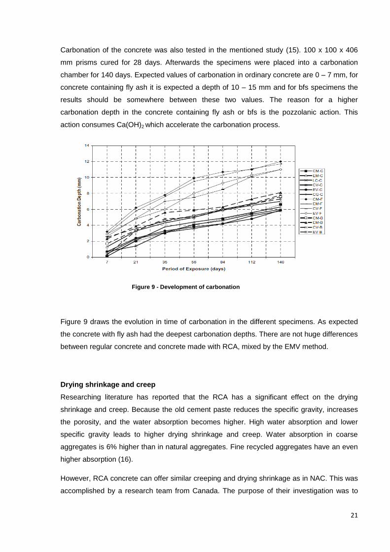
Carbonation of the concrete was also tested in the mentioned study (15). 100 x 100 x 406
mm prisms cured for 28 days. Afterwards the specimens were placed into a carbonation
chamber for 140 days. Expected values of carbonation in ordinary concrete are 0 – 7 mm, for
concrete containing fly ash it is expected a depth of 10 – 15 mm and for bfs specimens the
results should be somewhere between these two values. The reason for a higher
carbonation depth in the concrete containing fly ash or bfs is the pozzolanic action. This
action consumes Ca(OH)2 which accelerate the carbonation process.
Figure 9 draws the evolution in time of carbonation in the different specimens. As expected
the concrete with fly ash had the deepest carbonation depths. There are not huge differences
between regular concrete and concrete made with RCA, mixed by the EMV method.
Drying shrinkage and creep
Researching literature has reported that the RCA has a significant effect on the drying
shrinkage and creep. Because the old cement paste reduces the specific gravity, increases
the porosity, and the water absorption becomes higher. High water absorption and lower
specific gravity leads to higher drying shrinkage and creep. Water absorption in coarse
aggregates is 6% higher than in natural aggregates. Fine recycled aggregates have an even
higher absorption (16).
However, RCA concrete can offer similar creeping and drying shrinkage as in NAC. This was
accomplished by a research team from Canada. The purpose of their investigation was to
Figure 9 - Development of carbonation
22
see how the RCA concrete mixed by EMV method performed in shrinkage and creeping
tests. At creeping tests the RCA concrete performed even better than NAC. It was believed
that the reason for this result was that the total mortar volume was the same in both the RCA
concrete and the NAC. But the fresh mortar crept more than the old mortar in the RCA, and
in the NAC the amount of fresh mortar were highest (17).
RCA concrete in different countries
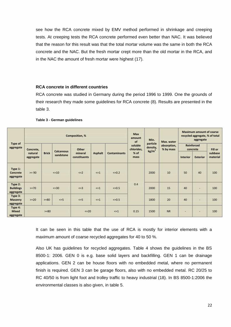
RCA concrete was studied in Germany during the period 1996 to 1999. One the grounds of
their research they made some guidelines for RCA concrete (8). Results are presented in the
table 3.
Table 3 - German guidelines
Type of aggregate
Composition, % Max
amount of
soluble chlorides,
% of mass
Min. particle density, kg/m3
Max. water absorption, % by mass
Maximum amount of coarse recycled aggregate, % of total
aggregate
Concrete, natural
aggregate Brick
Calcareous sandstone
Other mineral
constituents Asphalt Contaminants
Reinforced concrete Fill or
subbase material Interior Exterior
Type 1: Concrete aggregate
>= 90 <=10 <=2 <=1 <=0.2
0.4
2000 10 50 40 100
Type 2: Buildings aggregate
>=70 <=30 <=3 <=1 <=0.5 2000 15 40 - 100
Type 3: Masonry aggregate
>=20 >=80 <=5 <=5 <=1 <=0.5 1800 20 40 - 100
Type 4: Mixed
aggregate >=80 <=20 <=1 0.15 1500 NR - - 100
It can be seen in this table that the use of RCA is mostly for interior elements with a
maximum amount of coarse recycled aggregates for 40 to 50 %.
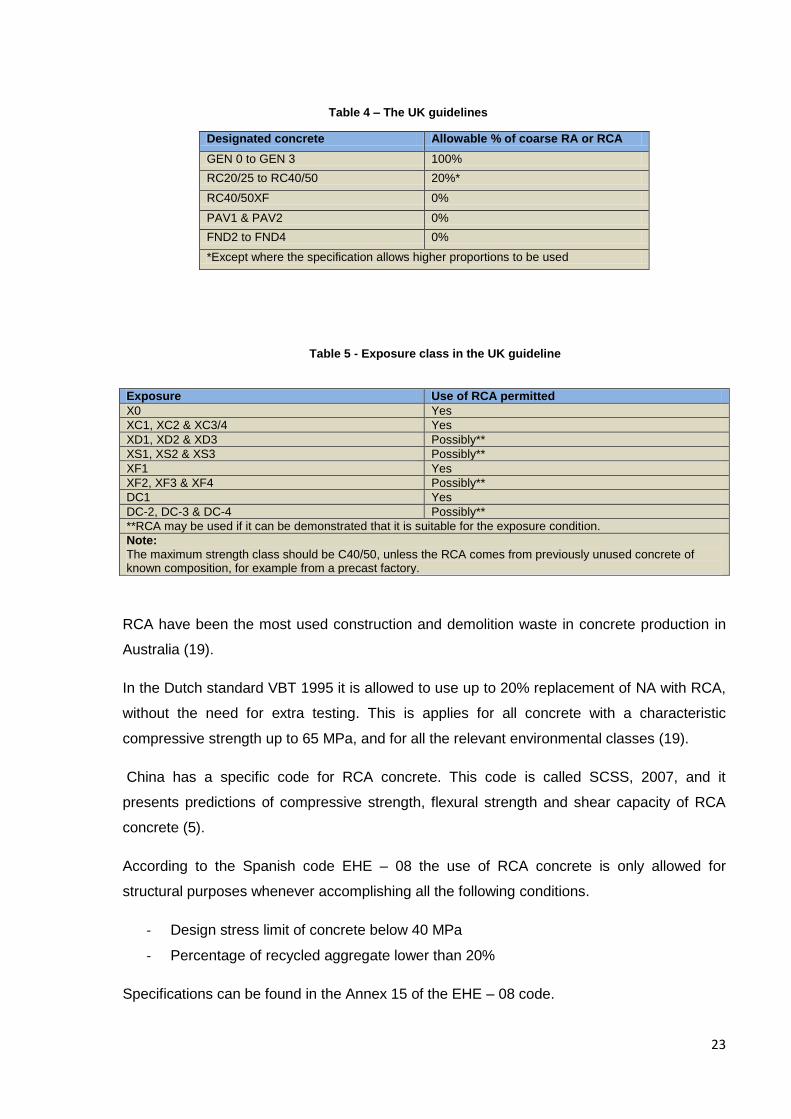
Also UK has guidelines for recycled aggregates. Table 4 shows the guidelines in the BS
8500-1: 2006. GEN 0 is e.g. base solid layers and backfilling. GEN 1 can be drainage
applications. GEN 2 can be house floors with no embedded metal, where no permanent
finish is required. GEN 3 can be garage floors, also with no embedded metal. RC 20/25 to
RC 40/50 is from light foot and trolley traffic to heavy industrial (18). In BS 8500-1:2006 the
environmental classes is also given, in table 5.
23
Designated concrete Allowable % of coarse RA or RCA
GEN 0 to GEN 3 100%
RC20/25 to RC40/50 20%*
RC40/50XF 0%
PAV1 & PAV2 0%
FND2 to FND4 0%
*Except where the specification allows higher proportions to be used
Exposure Use of RCA permitted
X0 Yes
XC1, XC2 & XC3/4 Yes
XD1, XD2 & XD3 Possibly**
XS1, XS2 & XS3 Possibly**
XF1 Yes
XF2, XF3 & XF4 Possibly**
DC1 Yes
DC-2, DC-3 & DC-4 Possibly**
**RCA may be used if it can be demonstrated that it is suitable for the exposure condition.
Note:
The maximum strength class should be C40/50, unless the RCA comes from previously unused concrete of known composition, for example from a precast factory.
RCA have been the most used construction and demolition waste in concrete production in
Australia (19).
In the Dutch standard VBT 1995 it is allowed to use up to 20% replacement of NA with RCA,
without the need for extra testing. This is applies for all concrete with a characteristic
compressive strength up to 65 MPa, and for all the relevant environmental classes (19).
China has a specific code for RCA concrete. This code is called SCSS, 2007, and it
presents predictions of compressive strength, flexural strength and shear capacity of RCA
concrete (5).
According to the Spanish code EHE – 08 the use of RCA concrete is only allowed for
structural purposes whenever accomplishing all the following conditions.
- Design stress limit of concrete below 40 MPa
- Percentage of recycled aggregate lower than 20%
Specifications can be found in the Annex 15 of the EHE – 08 code.
Table 4 – The UK guidelines
Table 5 - Exposure class in the UK guideline
24
In Singapore in 2012, RCA concrete was only used for low grade applications like backfilling
and constructions for temporary roads. But the Building Construction Authority of Singapore
have noticed that RCA can also be used for Structural grade concrete, and they have a plan
of using RCA concrete as a structural material in the future (7).
In the United States of America it is reported in 2004 that 41 states used RCA as aggregate.
Only 11 of them use it as aggregate in new concrete (20).
In Norway RCA concrete has been used as a building material in e.g. constructing a school.
The RCA concrete is used in foundations, walls and columns in about half of the basement.
35% of the coarse aggregates were replaced with recycled concrete in the size area of 10 to
20 mm. Another Norwegian example is a parking house near Oslo. Here the fundaments
were built of concrete with 20% RCA of the coarse aggregates in the size spread from 10 to
20 mm (21).
A Norwegian guideline was published dedicated for the use of recycled materials in concrete
production. The guideline contains information and specifications for the use of recycled
materials, among them RCA (22). It contains specifications on the production of the recycled
material, production of the concrete with recycled material and calculation rules. This
guideline is for concrete with an amount of RCA over 20 % of the aggregate weight. In
Norway the use of the conventional calculation methods can be used for reinforced concrete
as long as the amount of RCA is maintained below the 20% limit.
25
Contribution
The contribution is divided in three parts. The first part consists of calculations on a beam. I
have tried to compare the results from both a NAC beam and a RCA beam. The method may
not give the correct answers, but it gives a look on how the RCA reduces the compressive
strength in a beam, and how the reduction of the compressive strength affects the calculation
of the beam resistance. The calculation is enclosed as annex 1.I found it interesting to see
how the altering of the compressive strength changed the results of the calculation. Since
this is just calculated results, it would have been interesting to see how the experimental
results would have been.
Part two of my contribution is a excel worksheet. In this worksheet I have used a research
paper which presents the EMV method (23). I have made a worksheet where the input
values are the volumes of a regular concrete mix, and resulting in the volumes that are
needed if RCA is used. A printed copy of the worksheet is enclosed as annex 2.
The last part of my contribution is centered in some suggestions of non structural uses for
recycled concrete aggregates. I have focused on the use of RCA in bound form, and the use
of it in construction materials. This part consists of ideas and possibilities which can be
researched further. A summarizing table is enclosed as annex 3. It is not proven that the
suggested ideas will work, but it is non structural, and therefore can it be possible. The
reason for suggesting possible non structural applications are the fact that RCA concrete in
many countries is not allowed for structural uses or exceptionally limited.
How the reduction of the compressive strength affects the capacity of a beam
In this part I have used the equation suggested in a research paper and see how it affected
the results of a beam calculation. The equation can be found in a paper (4). And I have
presented it Equation 1. The equation is found form looking at the linear relationship between
the test results of RCA and NAC in compressive strength. It is not mentioned if this can be
used in the EC2, and the way I have used it to reduce the compressive strength in the
regular formulas for calculating resistance is not an approved method. But still I found it
interesting to see how the reduction affected the results.
The beam I used for the calculations is a 5000 mm long, and with a cross section of 300 x
400 mm. It is reinforced with 4 x Ø20 rebars in the tensile zone and 2 x Ø20 in the
compressive zone. The beam also has shear reinforcement. Stirrups with Ø10 and a spacing
26
of 180 mm are used. It is designed for an even distributed load. The concrete quality used is
B30. This is equal to the CEN C30/37 and has a characteristic compressive strength of 30
MPa. After reducing this with the suggested equation and using 100% replacement of the
coarse natural aggregate with RCA, the characteristic compressive strength became 24.38
MPa.
I have used formulas in the EC2 and the Norwegian national annex to design the beam. And
I have calculated one NAC beam and one RCA concrete beam. Because I wanted to test out
how equations proposed in research affect the strength of the beams. I have used a
reduction of the compressive strength because of RCA. This reduction has suggested in a
research paper (4). I am aware that I have taken some liberties when using this formula,
because it is not specified that this reduction can be used in EC2 calculations. And further it
is not approved methods I have used when calculating the moment, shear, creep and
shrinkage of the RCA beam. The calculations are done after the usual EC2 method, but I
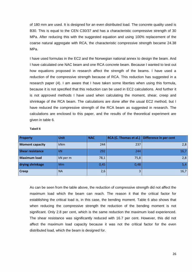
have reduced the compressive strength of the RCA beam as suggested in research. The
calculations are enclosed to this paper, and the results of the theoretical experiment are
given in table 6.
Tabell 6
Property Unit NAC RCA (C. Thomas et al.) Difference in per cent
Moment capacity kNm 244 237 2,8
Shear resistance kN 292 244 16,7
Maximum load kN per m 78,1 75,8 2,8
drying shrinkage Mm 0,45 0,48 5,4
Creep NA 2,6 3 16,7
As can be seen from the table above, the reduction of compressive strength did not affect the
maximum load which the beam can reach. The reason it that the critical factor for
establishing the critical load is, in this case, the bending moment. Table 6 also shows that
when reducing the compressive strength the reduction of the bending moment is not
significant. Only 2.8 per cent, which is the same reduction the maximum load experienced.
The shear resistance was significantly reduced with 16.7 per cent. However, this did not
affect the maximum load capacity because it was not the critical factor for the even
distributed load, which the beam is designed for.
27
Excel worksheet
To find out more about how the new mixture proportioning method for recycled concrete
aggregates work I have made an Excel worksheet. This is the list of needed input values.
Bulk specific gravity of
o Recycled concrete aggregates
o Natural aggregates
o The original virgin aggregates (The original aggregate in the RCA)
The residual mortar content in the RCA
The dry-rodded volume of the natural aggregate
The weights of the different components in the natural aggregate concrete
o Cement weight
o Water weight
o The oven dry natural aggregate weight
o The oven dry fine aggregate weight
These input values result in a complete concrete mixture with recycled aggregates. When
using this input values the volume content of the RCA concrete is found. The EMV method
takes into account the residual mortar volume in the recycled concrete aggregate, and
adjusts the volume of new cement paste. This means that the amount of natural aggregate,
both fine and coarse, cement and water is reduced. The RCA concrete needs admixtures like
water reducing and air-entraining admixtures. The air-entraining admixture is also often used
in the NAC. In fact it is used more air-entraining admixture in the NAC than in the RCA
concrete in most of the articles I have read.
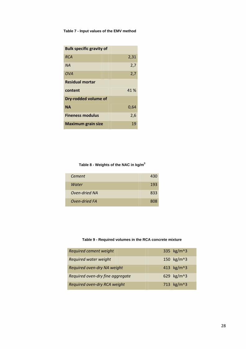
Below are some tables from the excel worksheet presented. Table 7 is the input values, and
table 8 is the input values of a conventional concrete mix with natural aggregates. Table 9 is
the mixture proportion of the RCA concrete. This concrete should have similar properties as
the conventional concrete mixture when it is cured. The last two tables are the differences
from the NAC and the RCA concrete and some environmental benefits which is a result of
the EMV method. Enclosed to my paper is the complete Excel worksheet.
28
Table 7 - Input values of the EMV method
Bulk specific gravity of
RCA 2,31
NA 2,7
OVA 2,7
Residual mortar
content 41 %
Dry-rodded volume of
NA 0,64
Fineness modulus 2,6
Maximum grain size 19
Table 8 - Weights of the NAC in kg/m3
Cement 430
Water 193
Oven-dried NA 833
Oven-dried FA 808
Table 9 - Required volumes in the RCA concrete mixture
Required cement weight 335 kg/m^3
Required water weight 150 kg/m^3
Required oven-dry NA weight 413 kg/m^3
Required oven-dry fine aggregate 629 kg/m^3
Required oven-dry RCA weight 713 kg/m^3
29
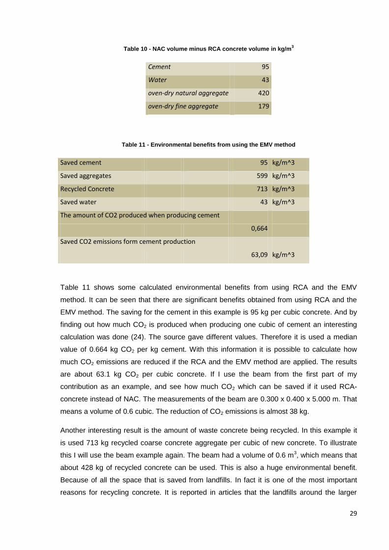
Table 10 - NAC volume minus RCA concrete volume in kg/m3
Cement 95
Water 43
oven-dry natural aggregate 420
oven-dry fine aggregate 179
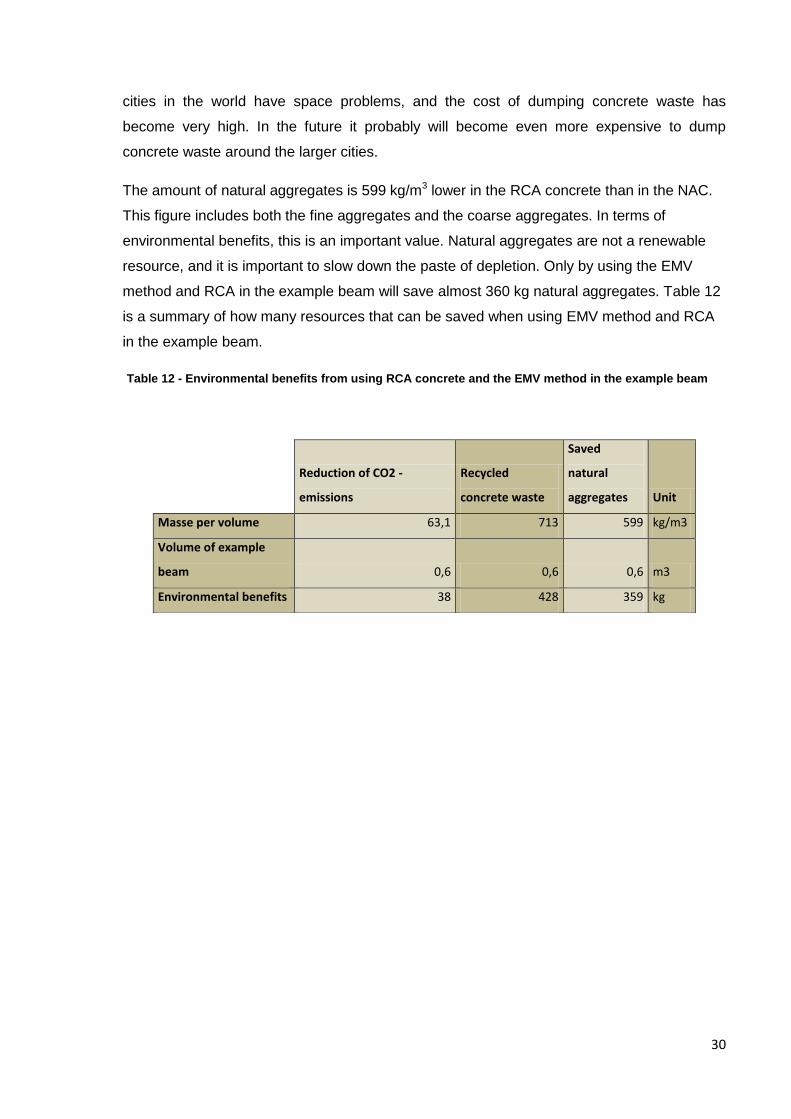
Table 11 - Environmental benefits from using the EMV method
Saved cement 95 kg/m^3
Saved aggregates 599 kg/m^3
Recycled Concrete 713 kg/m^3
Saved water 43 kg/m^3
The amount of CO2 produced when producing cement
0,664
Saved CO2 emissions form cement production
63,09 kg/m^3
Table 11 shows some calculated environmental benefits from using RCA and the EMV
method. It can be seen that there are significant benefits obtained from using RCA and the
EMV method. The saving for the cement in this example is 95 kg per cubic concrete. And by
finding out how much CO2 is produced when producing one cubic of cement an interesting
calculation was done (24). The source gave different values. Therefore it is used a median
value of 0.664 kg CO2 per kg cement. With this information it is possible to calculate how
much CO2 emissions are reduced if the RCA and the EMV method are applied. The results
are about 63.1 kg CO2 per cubic concrete. If I use the beam from the first part of my
contribution as an example, and see how much CO2 which can be saved if it used RCA-
concrete instead of NAC. The measurements of the beam are 0.300 x 0.400 x 5.000 m. That
means a volume of 0.6 cubic. The reduction of CO2 emissions is almost 38 kg.
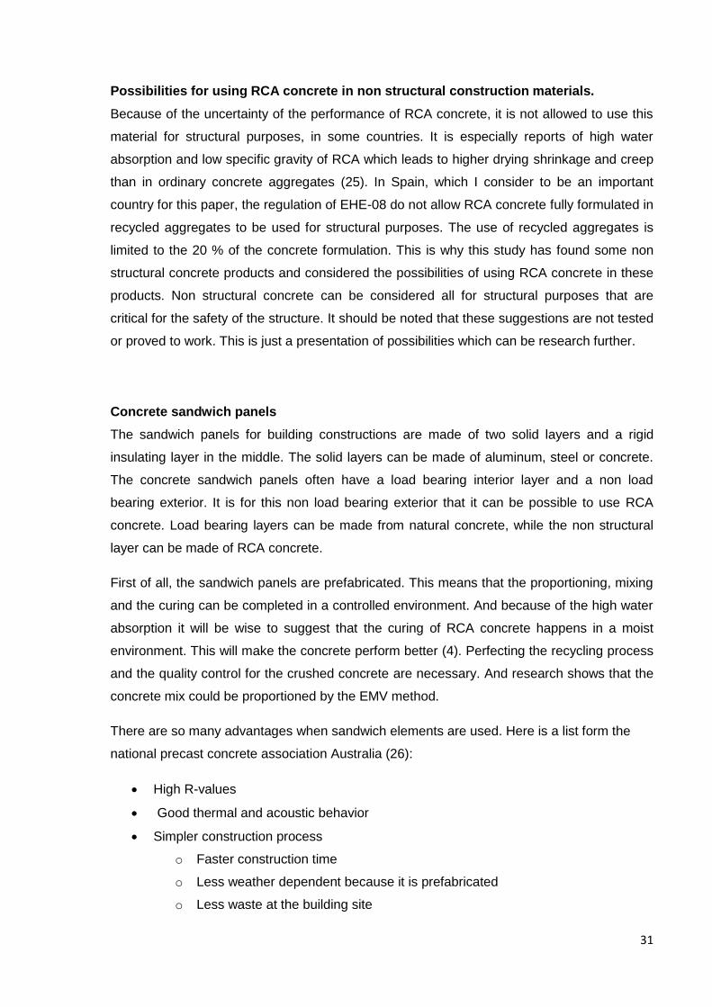
Another interesting result is the amount of waste concrete being recycled. In this example it
is used 713 kg recycled coarse concrete aggregate per cubic of new concrete. To illustrate
this I will use the beam example again. The beam had a volume of 0.6 m3, which means that
about 428 kg of recycled concrete can be used. This is also a huge environmental benefit.
Because of all the space that is saved from landfills. In fact it is one of the most important
reasons for recycling concrete. It is reported in articles that the landfills around the larger
30
cities in the world have space problems, and the cost of dumping concrete waste has
become very high. In the future it probably will become even more expensive to dump
concrete waste around the larger cities.
The amount of natural aggregates is 599 kg/m3 lower in the RCA concrete than in the NAC.
This figure includes both the fine aggregates and the coarse aggregates. In terms of
environmental benefits, this is an important value. Natural aggregates are not a renewable
resource, and it is important to slow down the paste of depletion. Only by using the EMV
method and RCA in the example beam will save almost 360 kg natural aggregates. Table 12
is a summary of how many resources that can be saved when using EMV method and RCA
in the example beam.
Table 12 - Environmental benefits from using RCA concrete and the EMV method in the example beam
Reduction of CO2 -
emissions
Recycled
concrete waste
Saved
natural
aggregates Unit
Masse per volume 63,1 713 599 kg/m3
Volume of example
beam 0,6 0,6 0,6 m3
Environmental benefits 38 428 359 kg
31
Possibilities for using RCA concrete in non structural construction materials.
Because of the uncertainty of the performance of RCA concrete, it is not allowed to use this
material for structural purposes, in some countries. It is especially reports of high water
absorption and low specific gravity of RCA which leads to higher drying shrinkage and creep
than in ordinary concrete aggregates (25). In Spain, which I consider to be an important
country for this paper, the regulation of EHE-08 do not allow RCA concrete fully formulated in
recycled aggregates to be used for structural purposes. The use of recycled aggregates is
limited to the 20 % of the concrete formulation. This is why this study has found some non
structural concrete products and considered the possibilities of using RCA concrete in these
products. Non structural concrete can be considered all for structural purposes that are
critical for the safety of the structure. It should be noted that these suggestions are not tested
or proved to work. This is just a presentation of possibilities which can be research further.
Concrete sandwich panels
The sandwich panels for building constructions are made of two solid layers and a rigid
insulating layer in the middle. The solid layers can be made of aluminum, steel or concrete.
The concrete sandwich panels often have a load bearing interior layer and a non load
bearing exterior. It is for this non load bearing exterior that it can be possible to use RCA
concrete. Load bearing layers can be made from natural concrete, while the non structural
layer can be made of RCA concrete.
First of all, the sandwich panels are prefabricated. This means that the proportioning, mixing
and the curing can be completed in a controlled environment. And because of the high water
absorption it will be wise to suggest that the curing of RCA concrete happens in a moist
environment. This will make the concrete perform better (4). Perfecting the recycling process
and the quality control for the crushed concrete are necessary. And research shows that the
concrete mix could be proportioned by the EMV method.
There are so many advantages when sandwich elements are used. Here is a list form the
national precast concrete association Australia (26):
High R-values
Good thermal and acoustic behavior
Simpler construction process
o Faster construction time
o Less weather dependent because it is prefabricated
o Less waste at the building site
32
There are a wide range of design possibilities
Fire resistant and durable
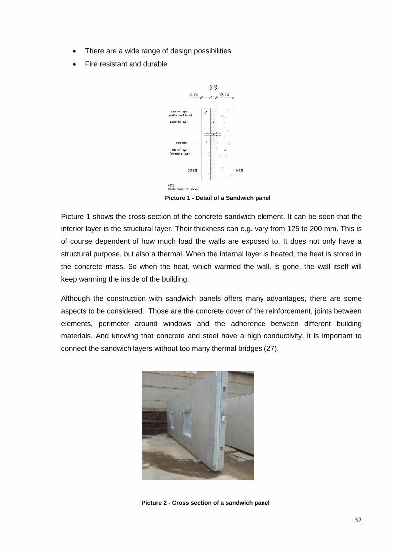
Picture 1 shows the cross-section of the concrete sandwich element. It can be seen that the
interior layer is the structural layer. Their thickness can e.g. vary from 125 to 200 mm. This is
of course dependent of how much load the walls are exposed to. It does not only have a
structural purpose, but also a thermal. When the internal layer is heated, the heat is stored in
the concrete mass. So when the heat, which warmed the wall, is gone, the wall itself will
keep warming the inside of the building.
Although the construction with sandwich panels offers many advantages, there are some
aspects to be considered. Those are the concrete cover of the reinforcement, joints between
elements, perimeter around windows and the adherence between different building
materials. And knowing that concrete and steel have a high conductivity, it is important to
connect the sandwich layers without too many thermal bridges (27).
Picture 1 - Detail of a Sandwich panel
Picture 2 - Cross section of a sandwich panel
33
The insulation layer is often made out of polystyrene, which is a type of plastic. In picture 2
we can see the blue rigid insolating layer. It is this layer which contributes the most to the R
value of this material. The R-value is a measure of the thermal resistance, and in concrete
sandwich panels R-values up to 3 m2 *K/W can be achieved (26).
Connectors are placed between the two concrete layers. Their main function is to distribute
loads between the concrete layers and making sure that the layers stay together. A company
called Owens Corning has a product called Pinkcore Insulated Concrete Sandwich Panel
Wall systems. They distributes polystyrene insulation and low conductivity wall ties. The wall
ties are made from thermoplastic resin (28).
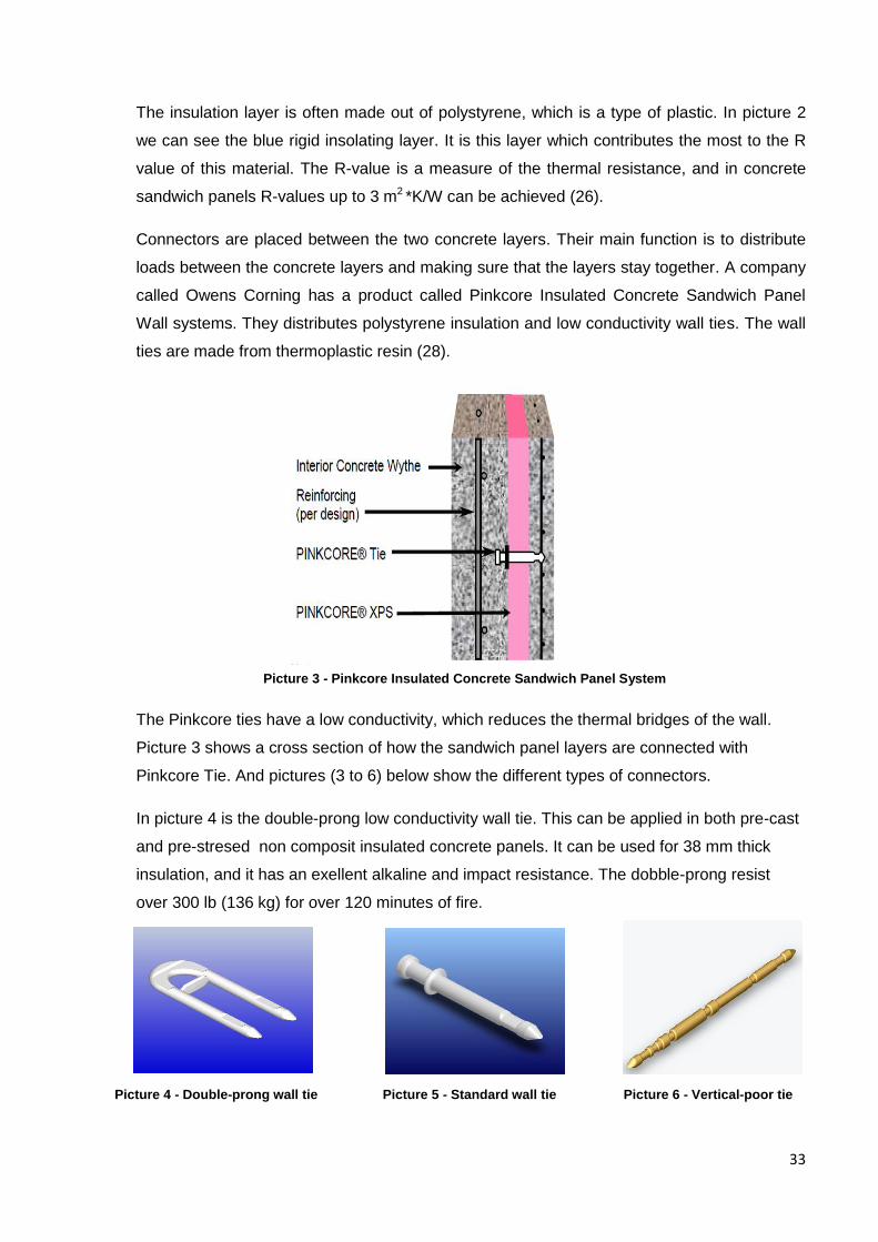
The Pinkcore ties have a low conductivity, which reduces the thermal bridges of the wall.
Picture 3 shows a cross section of how the sandwich panel layers are connected with
Pinkcore Tie. And pictures (3 to 6) below show the different types of connectors.
In picture 4 is the double-prong low conductivity wall tie. This can be applied in both pre-cast
and pre-stresed non composit insulated concrete panels. It can be used for 38 mm thick
insulation, and it has an exellent alkaline and impact resistance. The dobble-prong resist
over 300 lb (136 kg) for over 120 minutes of fire.
Picture 3 - Pinkcore Insulated Concrete Sandwich Panel System
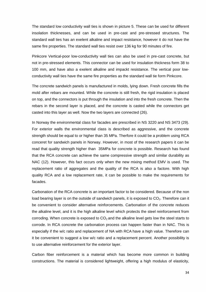
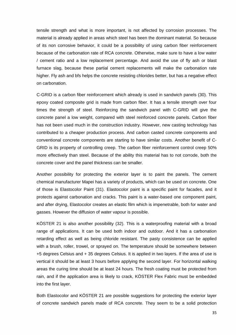
Picture 4 - Double-prong wall tie Picture 5 - Standard wall tie Picture 6 - Vertical-poor tie
34
The standard low conductivity wall ties is shown in picture 5. These can be used for different
insolation thicknesses, and can be used in pre-cast and pre-stressed structures. The
standard wall ties has an exelent alkaline and impact resistance, however it do not have the
same fire properties. The standard wall ties resist over 136 kg for 90 minutes of fire.
Pinkcore Vertical-poor low-conductivity wall ties can also be used in pre-cast concrete, but
not in pre-stressed elements. This connector can be used for insulation thickness form 38 to
100 mm, and have also a exelent alkaline and impackt resistance. The vertical poor low-
conductivity wall ties have the same fire properties as the standard wall tie form Pinkcore.
The concrete sandwich panels is manufactured in molds, lying down. Fresh concrete fills the
mold after rebars are mounted. While the concrete is still fresh, the rigid insulation is placed
on top, and the connectors is put through the insulation and into the fresh concrete. Then the
rebars in the second layer is placed, and the concrete is casted while the connectors get
casted into this layer as well. Now the two layers are connected (26).
In Norway the environmental class for facades are prescribed in NS 3220 and NS 3473 (29).
For exterior walls the environmental class is described as aggressive, and the concrete
strength should be equal to or higher than 35 MPa. Therfore it could be a problem using RCA
conceret for sandwich panels in Norway. However, in most of the research papers it can be
read that quality strength higher than 35MPa for concrete is possible. Research has found
that the RCA concrete can achieve the same compressive strength and similar durability as
NAC (12). However, this fact occurs only when the new mixing method EMV is used. The
replacement ratio of aggregates and the quality of the RCA is also a factore. With high
quality RCA and a low replacement rate, it can be possible to make the requirements for
facades.
Carbonation of the RCA concrete is an important factor to be considered. Because of the non
load bearing layer is on the outside of sandwich panels, it is exposed to CO2. Therefore can it
be convenient to consider alternative reinforcements. Carbonation of the concrete reduces
the alkaline level, and it is the high alkaline level which protects the steel reinforcement from
corroding. When concrete is exposed to CO2 and the alkaline level gets low the steel starts to
corrode. In RCA concrete the carbonation process can happen faster than in NAC. This is
especially if the w/c ratio and replacement of NA with RCA have a high value. Therefore can
it be convenient to suggest a low w/c ratio and a replacement percent. Another possibility is
to use alternative reinforcement for the exterior layer.
Carbon fiber reinforcement is a material which has become more common in building
constructions. The material is considered lightweight, offering a high modulus of elasticity,
35
tensile strength and what is more important, is not affected by corrosion processes. The
material is already applied in areas which steel has been the dominant material. So because
of its non corrosive behavior, it could be a possibility of using carbon fiber reinforcement
because of the carbonation rate of RCA concrete. Otherwise, make sure to have a low water
/ cement ratio and a low replacement percentage. And avoid the use of fly ash or blast
furnace slag, because these partial cement replacements will make the carbonation rate
higher. Fly ash and bfs helps the concrete resisting chlorides better, but has a negative effect
on carbonation.
C-GRID is a carbon fiber reinforcement which already is used in sandwich panels (30). This
epoxy coated composite grid is made from carbon fiber. It has a tensile strength over four
times the strength of steel. Reinforcing the sandwich panel with C-GRID will give the
concrete panel a low weight, compared with steel reinforced concrete panels. Carbon fiber
has not been used much in the construction industry. However, new casting technology has
contributed to a cheaper production process. And carbon casted concrete components and
conventional concrete components are starting to have similar costs. Another benefit of C-
GRID is its property of controlling creep. The carbon fiber reinforcement control creep 50%
more effectively than steel. Because of the ability this material has to not corrode, both the
concrete cover and the panel thickness can be smaller.
Another possibility for protecting the exterior layer is to paint the panels. The cement
chemical manufacturer Mapei has a variety of products, which can be used on concrete. One
of those is Elastocolor Paint (31). Elastocolor paint is a specific paint for facades, and it
protects against carbonation and cracks. This paint is a water-based one component paint,
and after drying, Elastocolor creates an elastic film which is impenetrable, both for water and
gasses. However the diffusion of water vapour is possible.
KÖSTER 21 is also another possibility (32). This is a waterproofing material with a broad
range of applications. It can be used both indoor and outdoor. And it has a carbonation
retarding effect as well as being chloride resistant. The pasty consistence can be applied
with a brush, roller, trowel, or sprayed on. The temperature should be somewhere between
+5 degrees Celsius and + 35 degrees Celsius. It is applied in two layers. If the area of use is
vertical it should be at least 3 hours before applying the second layer. For horizontal walking
areas the curing time should be at least 24 hours. The fresh coating must be protected from
rain, and if the application area is likely to crack, KÖSTER Flex Fabric must be embedded
into the first layer.
Both Elastocolor and KÖSTER 21 are possible suggestions for protecting the exterior layer
of concrete sandwich panels made of RCA concrete. They seem to be a solid protection
36
against outdoor climates. But research is needed to figure out how the RCA concrete and
these materials could perform properly.
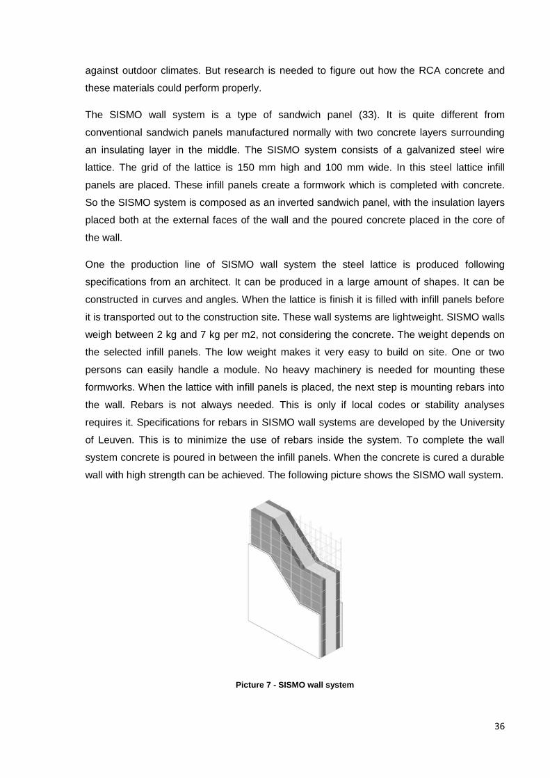
The SISMO wall system is a type of sandwich panel (33). It is quite different from
conventional sandwich panels manufactured normally with two concrete layers surrounding
an insulating layer in the middle. The SISMO system consists of a galvanized steel wire
lattice. The grid of the lattice is 150 mm high and 100 mm wide. In this steel lattice infill
panels are placed. These infill panels create a formwork which is completed with concrete.
So the SISMO system is composed as an inverted sandwich panel, with the insulation layers
placed both at the external faces of the wall and the poured concrete placed in the core of
the wall.
One the production line of SISMO wall system the steel lattice is produced following
specifications from an architect. It can be produced in a large amount of shapes. It can be
constructed in curves and angles. When the lattice is finish it is filled with infill panels before
it is transported out to the construction site. These wall systems are lightweight. SISMO walls
weigh between 2 kg and 7 kg per m2, not considering the concrete. The weight depends on
the selected infill panels. The low weight makes it very easy to build on site. One or two
persons can easily handle a module. No heavy machinery is needed for mounting these
formworks. When the lattice with infill panels is placed, the next step is mounting rebars into
the wall. Rebars is not always needed. This is only if local codes or stability analyses
requires it. Specifications for rebars in SISMO wall systems are developed by the University
of Leuven. This is to minimize the use of rebars inside the system. To complete the wall
system concrete is poured in between the infill panels. When the concrete is cured a durable
wall with high strength can be achieved. The following picture shows the SISMO wall system.
Picture 7 - SISMO wall system
37
There is a large amount of different infill systems which the architect can select. Hardboard
on both sides or one side hardboard and one side EPS. The EPS can be 40 mm or 80 mm.
Another choice is to have one side with 40 mm mineral wool and the other with 40 mm or 80
mm EPS. However, the most common is to use EPS on both sides. EPS is short for
expanded polystyrene. The SISMO walls come in different thickness. The thinnest is 60 mm
and the thickest is 500 mm. One module is 120 mm long and can be as high as 12 m.
So I want to suggest researching in how RCA concrete performs in SISMO wall systems.
Maybe it could be a possibility because it can be designed as a non structural wall. In a
building with conventional concrete in its critical structure, the SISMO wall filled with RCA
concrete can be applied as a climatic envelope. SISMO infill panels can be made out of
recycled materials. So if the concrete in the structure also is recycled if will make the wall a
good environmental alternative.
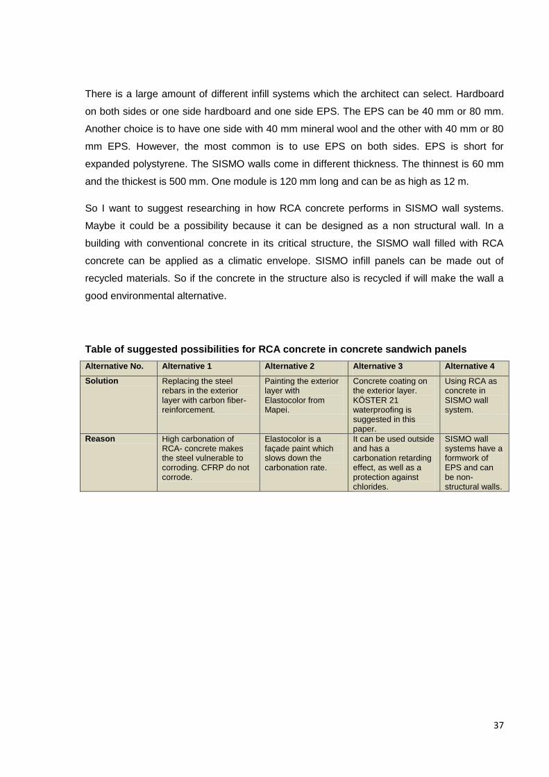
Table of suggested possibilities for RCA concrete in concrete sandwich panels
Alternative No. Alternative 1 Alternative 2 Alternative 3 Alternative 4
Solution Replacing the steel rebars in the exterior layer with carbon fiber-reinforcement.
Painting the exterior layer with Elastocolor from Mapei.
Concrete coating on the exterior layer. KÖSTER 21 waterproofing is suggested in this paper.
Using RCA as concrete in SISMO wall system.
Reason High carbonation of RCA- concrete makes the steel vulnerable to corroding. CFRP do not corrode.
Elastocolor is a façade paint which slows down the carbonation rate.
It can be used outside and has a carbonation retarding effect, as well as a protection against chlorides.
SISMO wall systems have a formwork of EPS and can be non-structural walls.
38
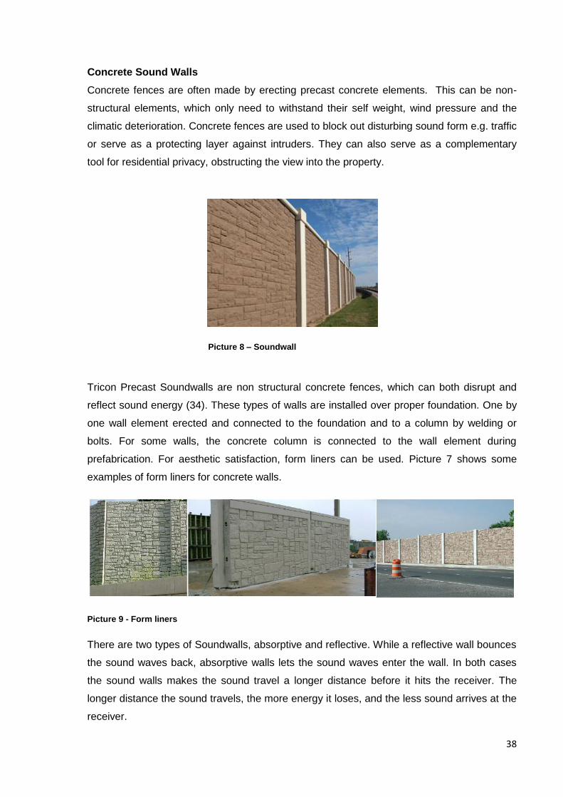
Concrete Sound Walls
Concrete fences are often made by erecting precast concrete elements. This can be non-
structural elements, which only need to withstand their self weight, wind pressure and the
climatic deterioration. Concrete fences are used to block out disturbing sound form e.g. traffic
or serve as a protecting layer against intruders. They can also serve as a complementary
tool for residential privacy, obstructing the view into the property.
Tricon Precast Soundwalls are non structural concrete fences, which can both disrupt and
reflect sound energy (34). These types of walls are installed over proper foundation. One by
one wall element erected and connected to the foundation and to a column by welding or
bolts. For some walls, the concrete column is connected to the wall element during
prefabrication. For aesthetic satisfaction, form liners can be used. Picture 7 shows some
examples of form liners for concrete walls.
Picture 9 - Form liners
There are two types of Soundwalls, absorptive and reflective. While a reflective wall bounces
the sound waves back, absorptive walls lets the sound waves enter the wall. In both cases
the sound walls makes the sound travel a longer distance before it hits the receiver. The
longer distance the sound travels, the more energy it loses, and the less sound arrives at the
receiver.
Picture 8 – Soundwall

39
Criteria which need to be fulfilled for soundwalls are a minimum density of 37 Ib/yd2 (20
kg/m2), sufficient height and at least eight times the length of the distance from the receiver
to the barrier (35). This can be seen in picture 10.The distance from the sound wall to the
receiver, also called the line of sight, should be the length which reduces the sound by 5dB.
The height of the wall than reduces the sound with 1.5 dB for each meter of height, as we
can see in picture 10. The decibel scale is a logarithmic scale and therefore is reductions of
1.5 dB a significant difference. E.g. a reduction of 9dB is equivalent of a reduction of 80 %
sound elimination.
Porosity of the material is very important for sound walls. And this is maybe a reason for
using RCA concrete in this application. I have not found any research on the sound
Picture 10 - Minimum length of the sound wall Picture 11 - The height of the wall reduces the sound
Picture 12 - Micrograph of the RCA structure Picture 13 - Detail image of the RCA microstructure
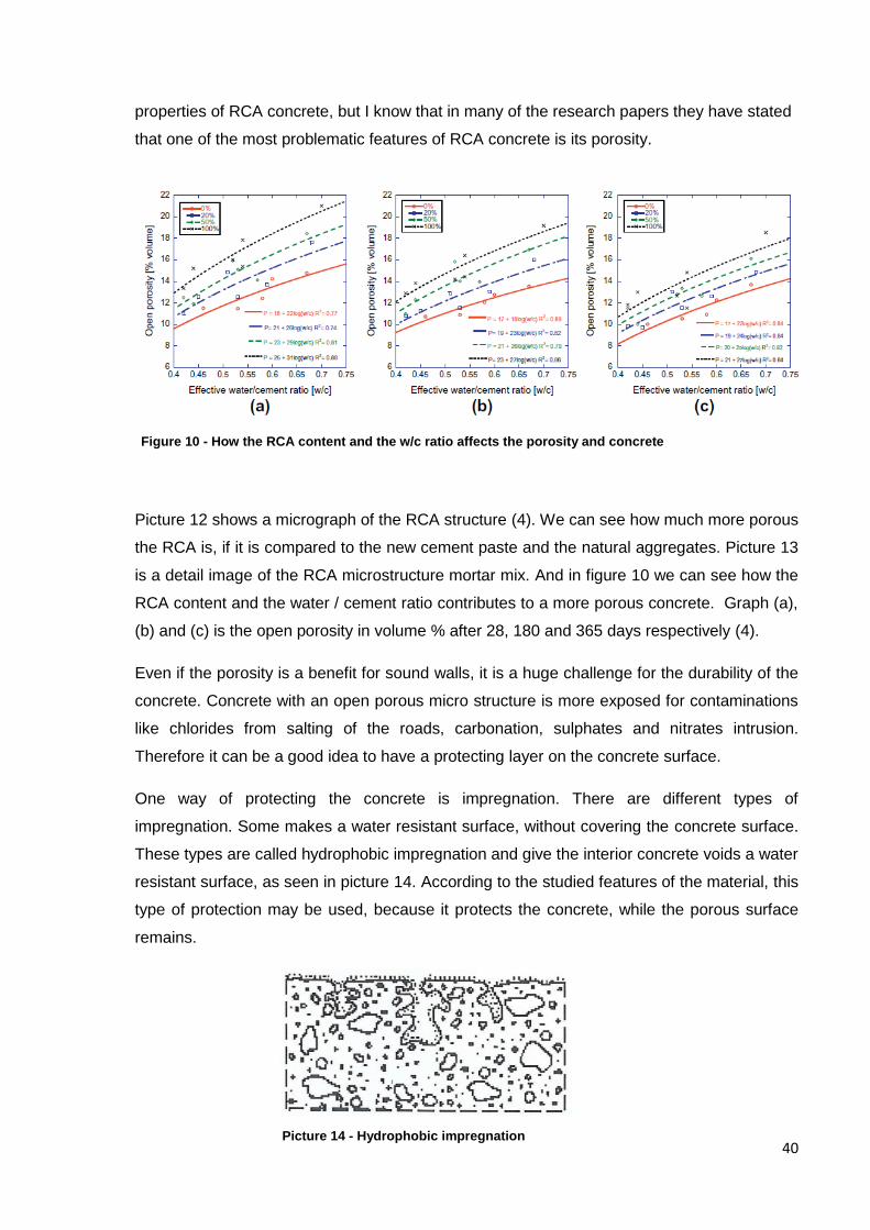
40
properties of RCA concrete, but I know that in many of the research papers they have stated
that one of the most problematic features of RCA concrete is its porosity.
Picture 12 shows a micrograph of the RCA structure (4). We can see how much more porous
the RCA is, if it is compared to the new cement paste and the natural aggregates. Picture 13
is a detail image of the RCA microstructure mortar mix. And in figure 10 we can see how the
RCA content and the water / cement ratio contributes to a more porous concrete. Graph (a),
(b) and (c) is the open porosity in volume % after 28, 180 and 365 days respectively (4).
Even if the porosity is a benefit for sound walls, it is a huge challenge for the durability of the
concrete. Concrete with an open porous micro structure is more exposed for contaminations
like chlorides from salting of the roads, carbonation, sulphates and nitrates intrusion.
Therefore it can be a good idea to have a protecting layer on the concrete surface.
One way of protecting the concrete is impregnation. There are different types of
impregnation. Some makes a water resistant surface, without covering the concrete surface.
These types are called hydrophobic impregnation and give the interior concrete voids a water
resistant surface, as seen in picture 14. According to the studied features of the material, this
type of protection may be used, because it protects the concrete, while the porous surface
remains.
Picture 14 - Hydrophobic impregnation
Figure 10 - How the RCA content and the w/c ratio affects the porosity and concrete

41
Another possibility of protecting the concrete is a dense impregnation or covering.
Impregnation protects the concrete by reducing surface voids. The voids become partial filled
and a thin, but not continuously film, covers the concrete. This is illustrated in picture 15.
The use of RCA concrete in sound walls can be a good alternative for utilizing waste
concrete. The huge amount of concrete waste needs to be taken advantage of, and this will
be even more important in the future. Governments around the world have already intentions
in reducing concrete waste, and to reach these goals new ideas are necessary. Research
about how RCA concrete performs in soundwalls is, important according to all papers
reviewed. The research should follow investigations of how RCA concrete performs as a
sound reducing element. And how RCA concrete will survive in the harsh outdoor climates
where soundwalls are constructed. Like along trafficked roads. Also studies on how the
impregnation and form liners coexist with RCA concrete would have been interesting.
Table of suggested possibilities of using RCA concrete in concrete sound walls
Alternative No. Alternative 1 Alternative 2 Alternative 3
Solution Using RCA concrete in absorptive sound walls with an impregnation which conserves the rough surface.
Using RCA concrete in reflecting sound walls with a concrete coating.
Using RCA concrete in sound walls with form liners.
Reason Pre cast concrete elements. Sound walls are not a critical structural element. RCA is a porous material, which can be good for sound absorption.
Pre cast concrete elements. Sound walls are not a critical structural element. Coating gives a good protection against the outdoor climate that the sound walls need to withstand.
Pre cast concrete elements. Sound walls are not a critical structural element. Form liners give an aesthetic wall with sound reducing properties.
Picture 15 - Impregnation
42
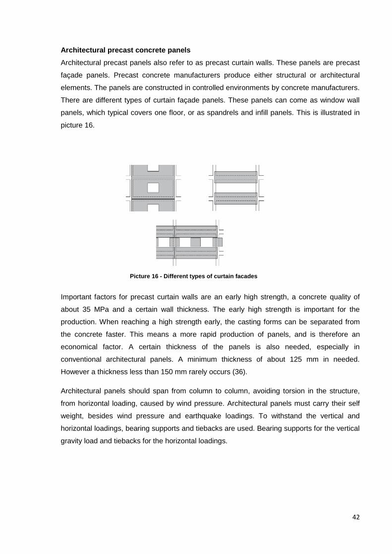
Architectural precast concrete panels
Architectural precast panels also refer to as precast curtain walls. These panels are precast
façade panels. Precast concrete manufacturers produce either structural or architectural
elements. The panels are constructed in controlled environments by concrete manufacturers.
There are different types of curtain façade panels. These panels can come as window wall
panels, which typical covers one floor, or as spandrels and infill panels. This is illustrated in
picture 16.
Important factors for precast curtain walls are an early high strength, a concrete quality of
about 35 MPa and a certain wall thickness. The early high strength is important for the
production. When reaching a high strength early, the casting forms can be separated from
the concrete faster. This means a more rapid production of panels, and is therefore an
economical factor. A certain thickness of the panels is also needed, especially in
conventional architectural panels. A minimum thickness of about 125 mm in needed.
However a thickness less than 150 mm rarely occurs (36).
Architectural panels should span from column to column, avoiding torsion in the structure,
from horizontal loading, caused by wind pressure. Architectural panels must carry their self
weight, besides wind pressure and earthquake loadings. To withstand the vertical and
horizontal loadings, bearing supports and tiebacks are used. Bearing supports for the vertical
gravity load and tiebacks for the horizontal loadings.
Picture 16 - Different types of curtain facades
43
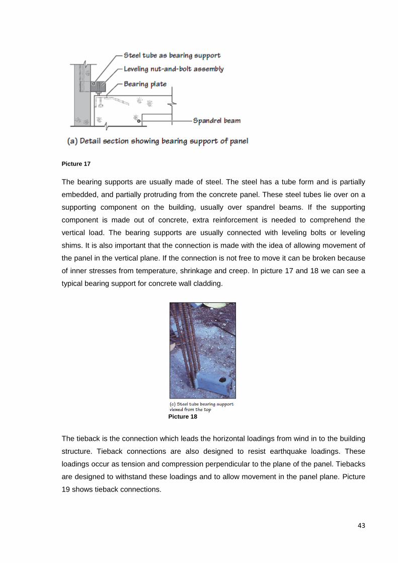
Picture 17
The bearing supports are usually made of steel. The steel has a tube form and is partially
embedded, and partially protruding from the concrete panel. These steel tubes lie over on a
supporting component on the building, usually over spandrel beams. If the supporting
component is made out of concrete, extra reinforcement is needed to comprehend the
vertical load. The bearing supports are usually connected with leveling bolts or leveling
shims. It is also important that the connection is made with the idea of allowing movement of
the panel in the vertical plane. If the connection is not free to move it can be broken because
of inner stresses from temperature, shrinkage and creep. In picture 17 and 18 we can see a
typical bearing support for concrete wall cladding.
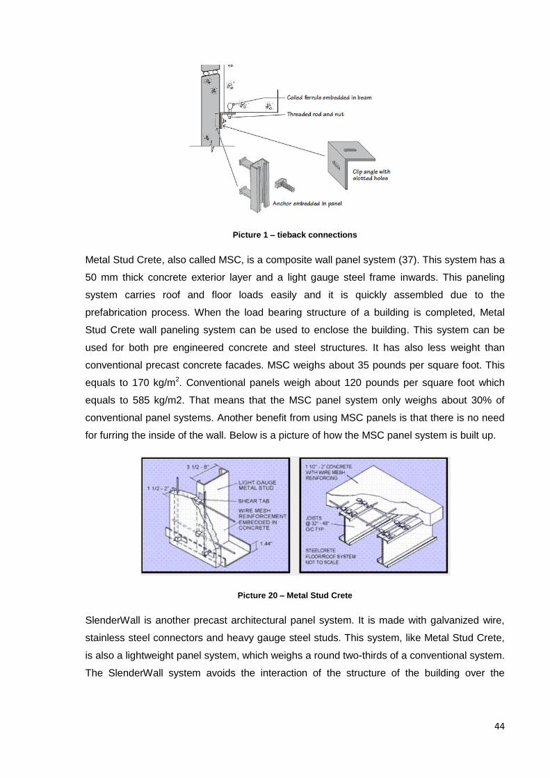
The tieback is the connection which leads the horizontal loadings from wind in to the building
structure. Tieback connections are also designed to resist earthquake loadings. These
loadings occur as tension and compression perpendicular to the plane of the panel. Tiebacks
are designed to withstand these loadings and to allow movement in the panel plane. Picture
19 shows tieback connections.
Picture 18
44
Picture 1 – tieback connections
Metal Stud Crete, also called MSC, is a composite wall panel system (37). This system has a
50 mm thick concrete exterior layer and a light gauge steel frame inwards. This paneling
system carries roof and floor loads easily and it is quickly assembled due to the
prefabrication process. When the load bearing structure of a building is completed, Metal
Stud Crete wall paneling system can be used to enclose the building. This system can be
used for both pre engineered concrete and steel structures. It has also less weight than
conventional precast concrete facades. MSC weighs about 35 pounds per square foot. This
equals to 170 kg/m2. Conventional panels weigh about 120 pounds per square foot which
equals to 585 kg/m2. That means that the MSC panel system only weighs about 30% of
conventional panel systems. Another benefit from using MSC panels is that there is no need
for furring the inside of the wall. Below is a picture of how the MSC panel system is built up.
Picture 20 – Metal Stud Crete
SlenderWall is another precast architectural panel system. It is made with galvanized wire,
stainless steel connectors and heavy gauge steel studs. This system, like Metal Stud Crete,
is also a lightweight panel system, which weighs a round two-thirds of a conventional system.
The SlenderWall system avoids the interaction of the structure of the building over the
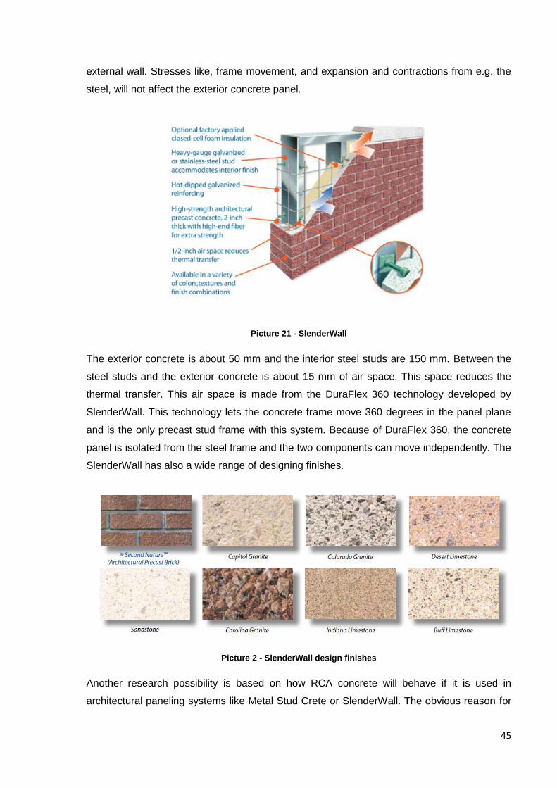
45
external wall. Stresses like, frame movement, and expansion and contractions from e.g. the
steel, will not affect the exterior concrete panel.
Picture 21 - SlenderWall
The exterior concrete is about 50 mm and the interior steel studs are 150 mm. Between the
steel studs and the exterior concrete is about 15 mm of air space. This space reduces the
thermal transfer. This air space is made from the DuraFlex 360 technology developed by
SlenderWall. This technology lets the concrete frame move 360 degrees in the panel plane
and is the only precast stud frame with this system. Because of DuraFlex 360, the concrete
panel is isolated from the steel frame and the two components can move independently. The
SlenderWall has also a wide range of designing finishes.
Picture 2 - SlenderWall design finishes
Another research possibility is based on how RCA concrete will behave if it is used in
architectural paneling systems like Metal Stud Crete or SlenderWall. The obvious reason for
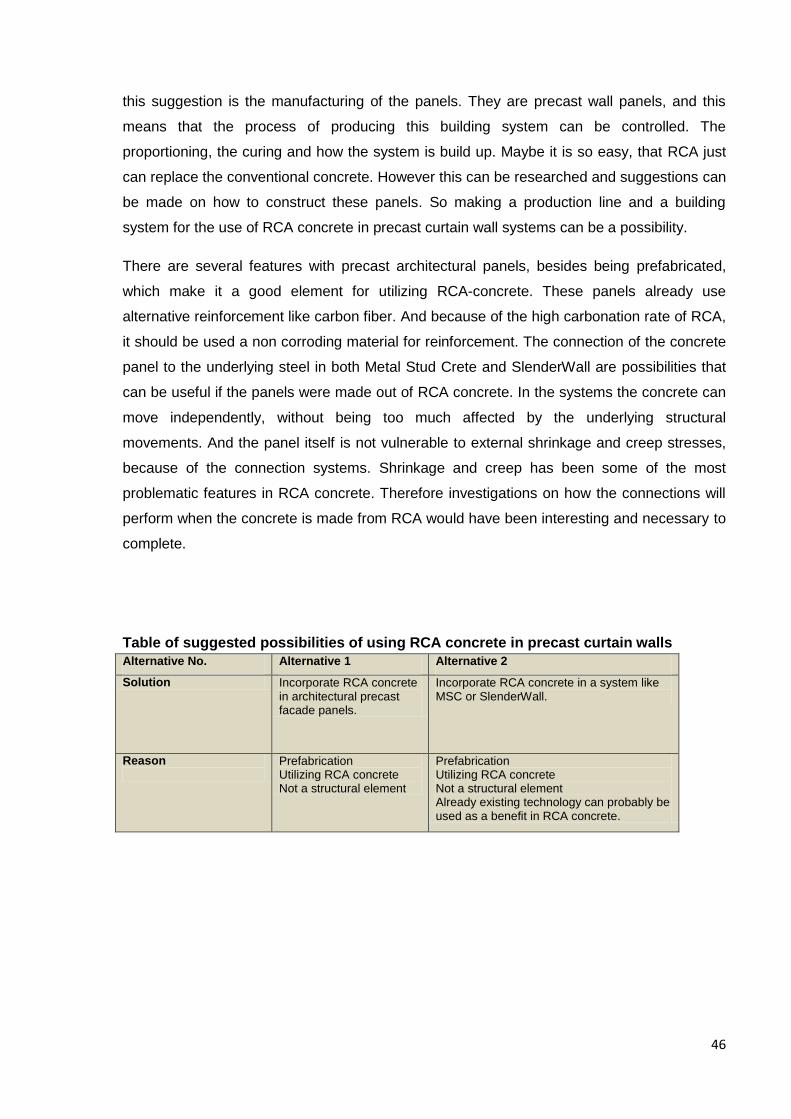
46
this suggestion is the manufacturing of the panels. They are precast wall panels, and this
means that the process of producing this building system can be controlled. The
proportioning, the curing and how the system is build up. Maybe it is so easy, that RCA just
can replace the conventional concrete. However this can be researched and suggestions can
be made on how to construct these panels. So making a production line and a building
system for the use of RCA concrete in precast curtain wall systems can be a possibility.
There are several features with precast architectural panels, besides being prefabricated,
which make it a good element for utilizing RCA-concrete. These panels already use
alternative reinforcement like carbon fiber. And because of the high carbonation rate of RCA,
it should be used a non corroding material for reinforcement. The connection of the concrete
panel to the underlying steel in both Metal Stud Crete and SlenderWall are possibilities that
can be useful if the panels were made out of RCA concrete. In the systems the concrete can
move independently, without being too much affected by the underlying structural
movements. And the panel itself is not vulnerable to external shrinkage and creep stresses,
because of the connection systems. Shrinkage and creep has been some of the most
problematic features in RCA concrete. Therefore investigations on how the connections will
perform when the concrete is made from RCA would have been interesting and necessary to
complete.
Table of suggested possibilities of using RCA concrete in precast curtain walls
Alternative No. Alternative 1 Alternative 2
Solution Incorporate RCA concrete in architectural precast facade panels.
Incorporate RCA concrete in a system like MSC or SlenderWall.
Reason
Prefabrication Utilizing RCA concrete Not a structural element
Prefabrication Utilizing RCA concrete Not a structural element Already existing technology can probably be used as a benefit in RCA concrete.
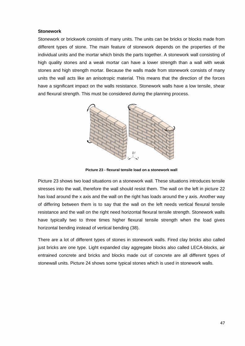
47
Stonework
Stonework or brickwork consists of many units. The units can be bricks or blocks made from
different types of stone. The main feature of stonework depends on the properties of the
individual units and the mortar which binds the parts together. A stonework wall consisting of
high quality stones and a weak mortar can have a lower strength than a wall with weak
stones and high strength mortar. Because the walls made from stonework consists of many
units the wall acts like an anisotropic material. This means that the direction of the forces
have a significant impact on the walls resistance. Stonework walls have a low tensile, shear
and flexural strength. This must be considered during the planning process.
Picture 23 - flexural tensile load on a stonework wall
Picture 23 shows two load situations on a stonework wall. These situations introduces tensile
stresses into the wall, therefore the wall should resist them. The wall on the left in picture 22
has load around the x axis and the wall on the right has loads around the y axis. Another way
of differing between them is to say that the wall on the left needs vertical flexural tensile
resistance and the wall on the right need horizontal flexural tensile strength. Stonework walls
have typically two to three times higher flexural tensile strength when the load gives
horizontal bending instead of vertical bending (38).
There are a lot of different types of stones in stonework walls. Fired clay bricks also called
just bricks are one type. Light expanded clay aggregate blocks also called LECA-blocks, air
entrained concrete and bricks and blocks made out of concrete are all different types of
stonewall units. Picture 24 shows some typical stones which is used in stonework walls.
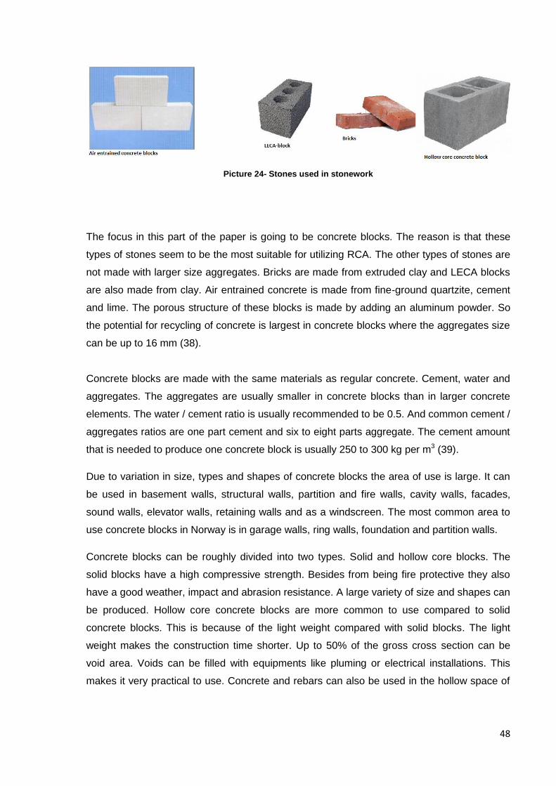
48
Picture 24- Stones used in stonework
The focus in this part of the paper is going to be concrete blocks. The reason is that these
types of stones seem to be the most suitable for utilizing RCA. The other types of stones are
not made with larger size aggregates. Bricks are made from extruded clay and LECA blocks
are also made from clay. Air entrained concrete is made from fine-ground quartzite, cement
and lime. The porous structure of these blocks is made by adding an aluminum powder. So
the potential for recycling of concrete is largest in concrete blocks where the aggregates size
can be up to 16 mm (38).
Concrete blocks are made with the same materials as regular concrete. Cement, water and
aggregates. The aggregates are usually smaller in concrete blocks than in larger concrete
elements. The water / cement ratio is usually recommended to be 0.5. And common cement /
aggregates ratios are one part cement and six to eight parts aggregate. The cement amount
that is needed to produce one concrete block is usually 250 to 300 kg per m3 (39).
Due to variation in size, types and shapes of concrete blocks the area of use is large. It can
be used in basement walls, structural walls, partition and fire walls, cavity walls, facades,
sound walls, elevator walls, retaining walls and as a windscreen. The most common area to
use concrete blocks in Norway is in garage walls, ring walls, foundation and partition walls.
Concrete blocks can be roughly divided into two types. Solid and hollow core blocks. The
solid blocks have a high compressive strength. Besides from being fire protective they also
have a good weather, impact and abrasion resistance. A large variety of size and shapes can
be produced. Hollow core concrete blocks are more common to use compared to solid
concrete blocks. This is because of the light weight compared with solid blocks. The light
weight makes the construction time shorter. Up to 50% of the gross cross section can be
void area. Voids can be filled with equipments like pluming or electrical installations. This
makes it very practical to use. Concrete and rebars can also be used in the hollow space of
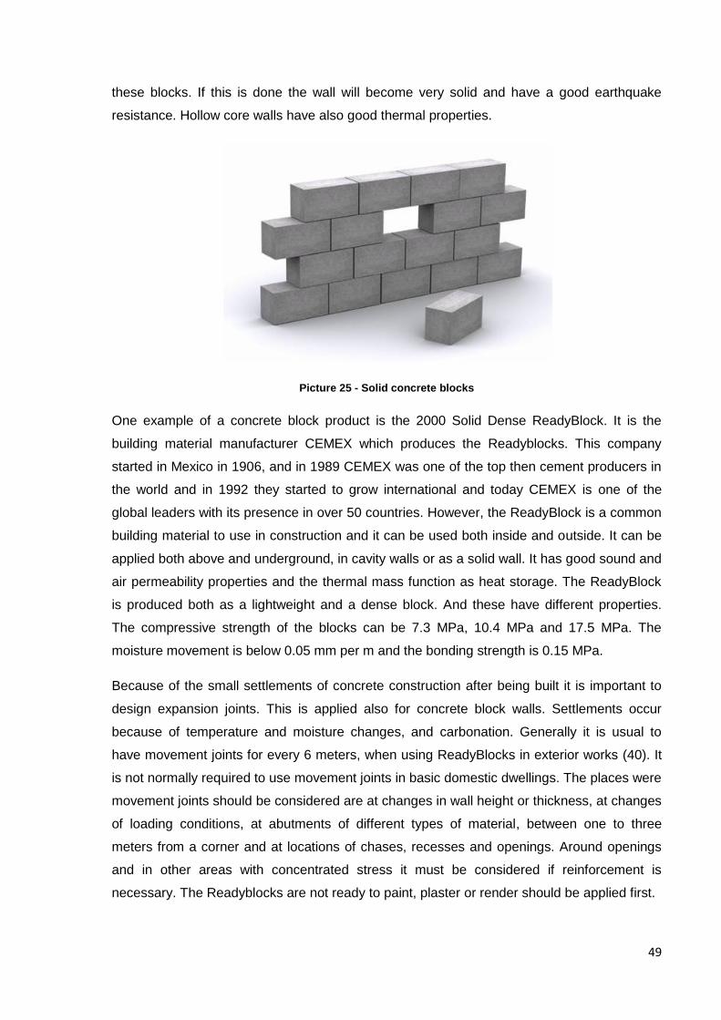
49
these blocks. If this is done the wall will become very solid and have a good earthquake
resistance. Hollow core walls have also good thermal properties.
Picture 25 - Solid concrete blocks
One example of a concrete block product is the 2000 Solid Dense ReadyBlock. It is the
building material manufacturer CEMEX which produces the Readyblocks. This company
started in Mexico in 1906, and in 1989 CEMEX was one of the top then cement producers in
the world and in 1992 they started to grow international and today CEMEX is one of the
global leaders with its presence in over 50 countries. However, the ReadyBlock is a common
building material to use in construction and it can be used both inside and outside. It can be
applied both above and underground, in cavity walls or as a solid wall. It has good sound and
air permeability properties and the thermal mass function as heat storage. The ReadyBlock
is produced both as a lightweight and a dense block. And these have different properties.
The compressive strength of the blocks can be 7.3 MPa, 10.4 MPa and 17.5 MPa. The
moisture movement is below 0.05 mm per m and the bonding strength is 0.15 MPa.
Because of the small settlements of concrete construction after being built it is important to
design expansion joints. This is applied also for concrete block walls. Settlements occur
because of temperature and moisture changes, and carbonation. Generally it is usual to
have movement joints for every 6 meters, when using ReadyBlocks in exterior works (40). It
is not normally required to use movement joints in basic domestic dwellings. The places were
movement joints should be considered are at changes in wall height or thickness, at changes
of loading conditions, at abutments of different types of material, between one to three
meters from a corner and at locations of chases, recesses and openings. Around openings
and in other areas with concentrated stress it must be considered if reinforcement is
necessary. The Readyblocks are not ready to paint, plaster or render should be applied first.

50
ReadyBlocks are not currently produced with any recycled material. But these types of
concrete blocks can be an alternative to use RCA. The CEMEX Company has a clear goal to
create sustainable materials, and have already taken some steps. Furnace bottom slag is
used and all of the packaging of ReadyBlocks is 100% recycled. It is also mentioned that
ReadyBlocks contains dust which otherwise would go to the landfill. CEMEX are working with
the possibility of using recycled materials to replace the virgin aggregates in the blocks.
There are some attempts in applying this technology (41).
Picture 26 - 2000 Solid Dense ReadyBlock (Standard finish)
There is another company which already has applied recycled materials into concrete blocks.
This company is called Aggregates Industries. It is a manufacturer of heavy building
materials for the construction industry. And is a member of the company Holcim Group and it
is also the first company in the world which got a BES 6001 certificate. Other certificates are
ISO 9001, ISO 14001 and OHSAS 18001. Aggregates industries are working for sustainable
solutions for their market.
One of the products from Aggregates Industries is Enviroblock. The aggregates in these
types of concrete blocks consist of minimum 80% recycled materials. But it is possible to get
as much as 100% recycled aggregates in Enviroblocks. The recycled materials are china
clay and recycled concrete aggregates. RCA is thoroughly described in this paper and china
is produced from crushed waste rock and can be used in a variety of applications. Examples
are similar to RCA e.g. in bitumen bound materials, concrete, pipe bedding, and unbound
mixtures for sub-base, chapping, embankments and fill. The use of China clay in concrete is
as a replacement for the fine aggregates, while RCA is usually used for course aggregates.
All the products in Enviroblocks are approved by the European and the UK standards. All the
blocks are produced after the quality procedures of BS EN ISO 9001 2000. This lead to a
compliance with the BS EN 771-3:2003. The concrete blocks fit into the Category 1 masonry
units.
Enviroblocks can be used in both internal and external constructions. They can be used both
over and under the DPC (Damp Proof Course). And they are especially suitable for locations
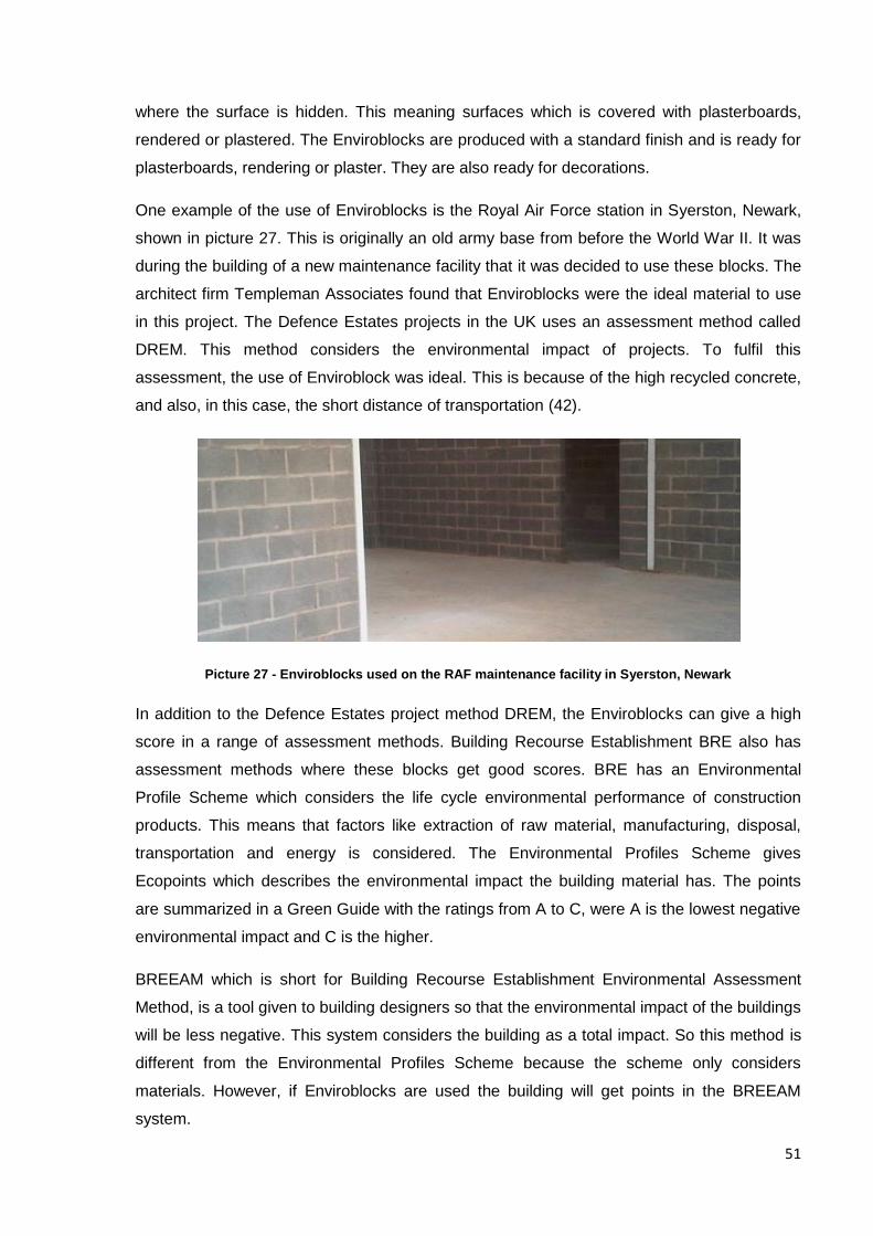
51
where the surface is hidden. This meaning surfaces which is covered with plasterboards,
rendered or plastered. The Enviroblocks are produced with a standard finish and is ready for
plasterboards, rendering or plaster. They are also ready for decorations.
One example of the use of Enviroblocks is the Royal Air Force station in Syerston, Newark,
shown in picture 27. This is originally an old army base from before the World War II. It was
during the building of a new maintenance facility that it was decided to use these blocks. The
architect firm Templeman Associates found that Enviroblocks were the ideal material to use
in this project. The Defence Estates projects in the UK uses an assessment method called
DREM. This method considers the environmental impact of projects. To fulfil this
assessment, the use of Enviroblock was ideal. This is because of the high recycled concrete,
and also, in this case, the short distance of transportation (42).
Picture 27 - Enviroblocks used on the RAF maintenance facility in Syerston, Newark
In addition to the Defence Estates project method DREM, the Enviroblocks can give a high
score in a range of assessment methods. Building Recourse Establishment BRE also has
assessment methods where these blocks get good scores. BRE has an Environmental
Profile Scheme which considers the life cycle environmental performance of construction
products. This means that factors like extraction of raw material, manufacturing, disposal,
transportation and energy is considered. The Environmental Profiles Scheme gives
Ecopoints which describes the environmental impact the building material has. The points
are summarized in a Green Guide with the ratings from A to C, were A is the lowest negative
environmental impact and C is the higher.
BREEAM which is short for Building Recourse Establishment Environmental Assessment
Method, is a tool given to building designers so that the environmental impact of the buildings
will be less negative. This system considers the building as a total impact. So this method is
different from the Environmental Profiles Scheme because the scheme only considers
materials. However, if Enviroblocks are used the building will get points in the BREEAM
system.
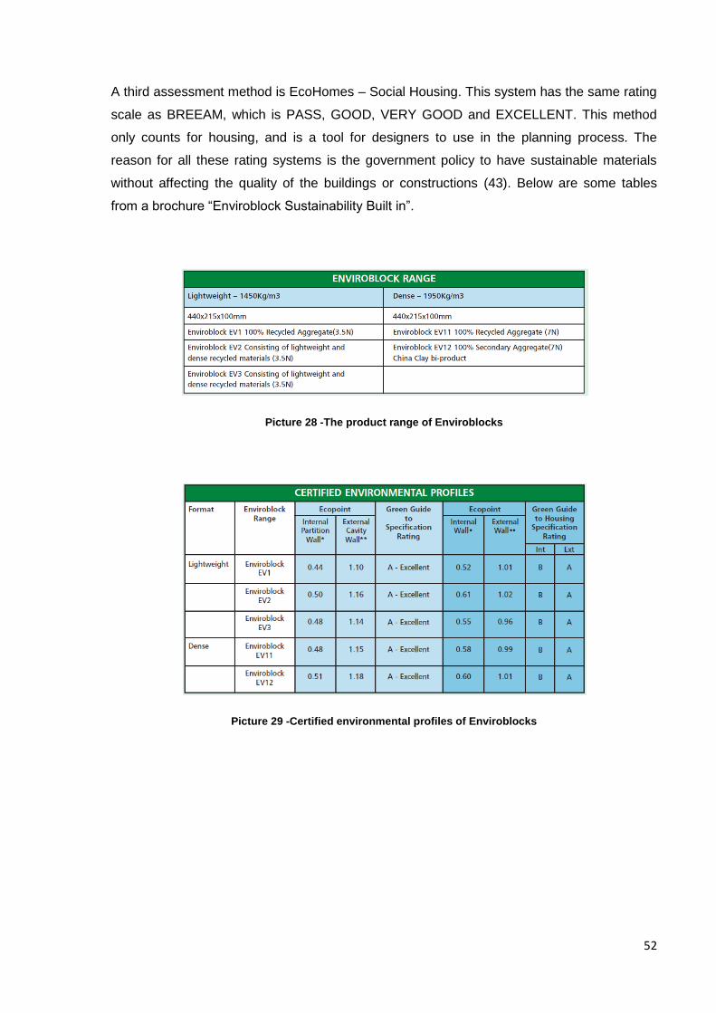
52
A third assessment method is EcoHomes – Social Housing. This system has the same rating
scale as BREEAM, which is PASS, GOOD, VERY GOOD and EXCELLENT. This method
only counts for housing, and is a tool for designers to use in the planning process. The
reason for all these rating systems is the government policy to have sustainable materials
without affecting the quality of the buildings or constructions (43). Below are some tables
from a brochure “Enviroblock Sustainability Built in”.
Picture 28 -The product range of Enviroblocks
Picture 29 -Certified environmental profiles of Enviroblocks
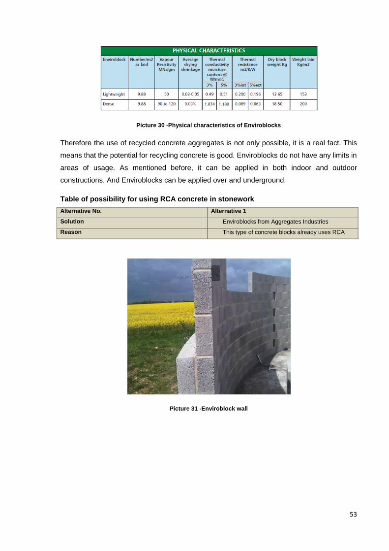
53
Picture 30 -Physical characteristics of Enviroblocks
Therefore the use of recycled concrete aggregates is not only possible, it is a real fact. This
means that the potential for recycling concrete is good. Enviroblocks do not have any limits in
areas of usage. As mentioned before, it can be applied in both indoor and outdoor
constructions. And Enviroblocks can be applied over and underground.
Table of possibility for using RCA concrete in stonework
Alternative No. Alternative 1
Solution Enviroblocks from Aggregates Industries
Reason This type of concrete blocks already uses RCA
Picture 31 -Enviroblock wall
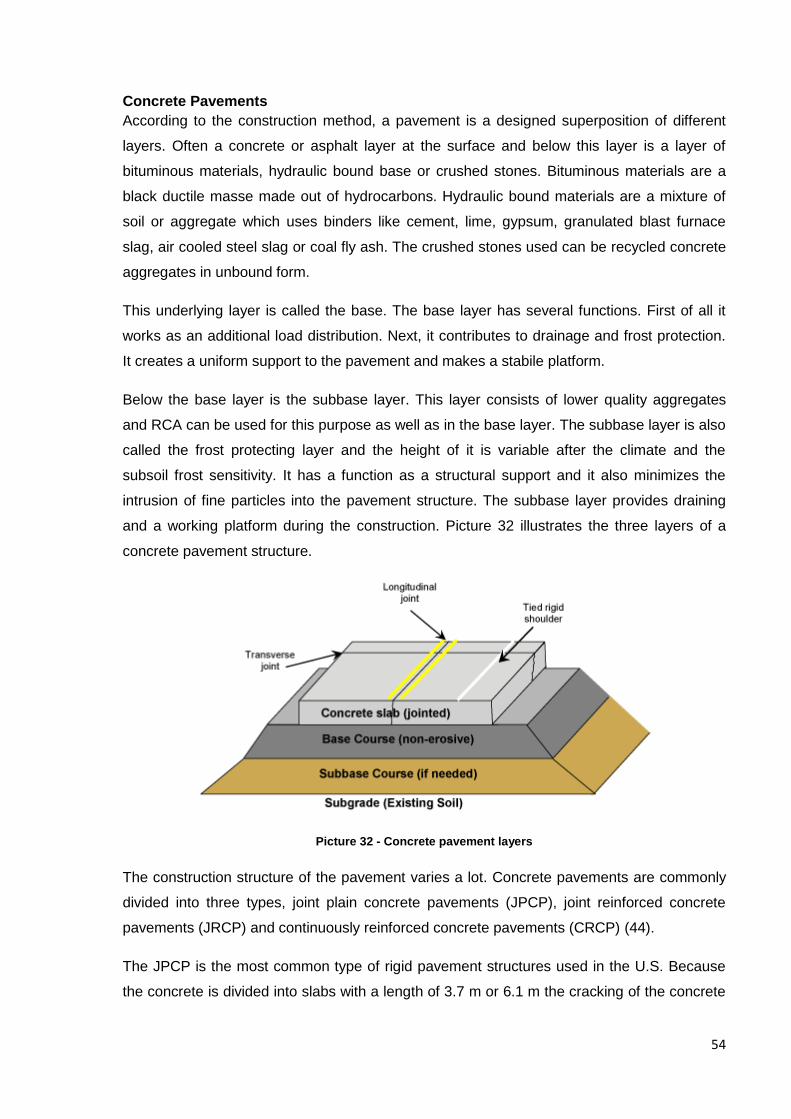
54
Concrete Pavements
According to the construction method, a pavement is a designed superposition of different
layers. Often a concrete or asphalt layer at the surface and below this layer is a layer of
bituminous materials, hydraulic bound base or crushed stones. Bituminous materials are a
black ductile masse made out of hydrocarbons. Hydraulic bound materials are a mixture of
soil or aggregate which uses binders like cement, lime, gypsum, granulated blast furnace
slag, air cooled steel slag or coal fly ash. The crushed stones used can be recycled concrete
aggregates in unbound form.
This underlying layer is called the base. The base layer has several functions. First of all it
works as an additional load distribution. Next, it contributes to drainage and frost protection.
It creates a uniform support to the pavement and makes a stabile platform.
Below the base layer is the subbase layer. This layer consists of lower quality aggregates
and RCA can be used for this purpose as well as in the base layer. The subbase layer is also
called the frost protecting layer and the height of it is variable after the climate and the
subsoil frost sensitivity. It has a function as a structural support and it also minimizes the
intrusion of fine particles into the pavement structure. The subbase layer provides draining
and a working platform during the construction. Picture 32 illustrates the three layers of a
concrete pavement structure.
Picture 32 - Concrete pavement layers
The construction structure of the pavement varies a lot. Concrete pavements are commonly
divided into three types, joint plain concrete pavements (JPCP), joint reinforced concrete
pavements (JRCP) and continuously reinforced concrete pavements (CRCP) (44).
The JPCP is the most common type of rigid pavement structures used in the U.S. Because
the concrete is divided into slabs with a length of 3.7 m or 6.1 m the cracking of the concrete
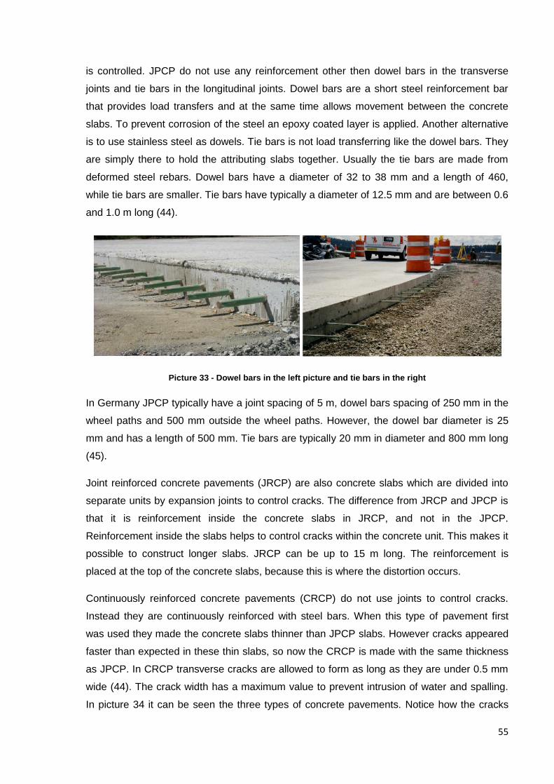
55
is controlled. JPCP do not use any reinforcement other then dowel bars in the transverse
joints and tie bars in the longitudinal joints. Dowel bars are a short steel reinforcement bar
that provides load transfers and at the same time allows movement between the concrete
slabs. To prevent corrosion of the steel an epoxy coated layer is applied. Another alternative
is to use stainless steel as dowels. Tie bars is not load transferring like the dowel bars. They
are simply there to hold the attributing slabs together. Usually the tie bars are made from
deformed steel rebars. Dowel bars have a diameter of 32 to 38 mm and a length of 460,
while tie bars are smaller. Tie bars have typically a diameter of 12.5 mm and are between 0.6
and 1.0 m long (44).
Picture 33 - Dowel bars in the left picture and tie bars in the right
In Germany JPCP typically have a joint spacing of 5 m, dowel bars spacing of 250 mm in the
wheel paths and 500 mm outside the wheel paths. However, the dowel bar diameter is 25
mm and has a length of 500 mm. Tie bars are typically 20 mm in diameter and 800 mm long
(45).
Joint reinforced concrete pavements (JRCP) are also concrete slabs which are divided into
separate units by expansion joints to control cracks. The difference from JRCP and JPCP is
that it is reinforcement inside the concrete slabs in JRCP, and not in the JPCP.
Reinforcement inside the slabs helps to control cracks within the concrete unit. This makes it
possible to construct longer slabs. JRCP can be up to 15 m long. The reinforcement is
placed at the top of the concrete slabs, because this is where the distortion occurs.
Continuously reinforced concrete pavements (CRCP) do not use joints to control cracks.
Instead they are continuously reinforced with steel bars. When this type of pavement first
was used they made the concrete slabs thinner than JPCP slabs. However cracks appeared
faster than expected in these thin slabs, so now the CRCP is made with the same thickness
as JPCP. In CRCP transverse cracks are allowed to form as long as they are under 0.5 mm
wide (44). The crack width has a maximum value to prevent intrusion of water and spalling.
In picture 34 it can be seen the three types of concrete pavements. Notice how the cracks
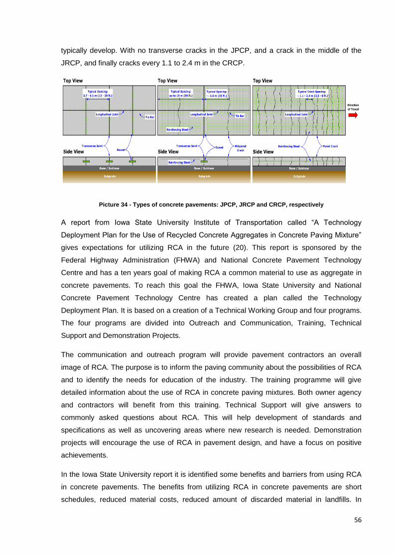
56
typically develop. With no transverse cracks in the JPCP, and a crack in the middle of the
JRCP, and finally cracks every 1.1 to 2.4 m in the CRCP.
Picture 34 - Types of concrete pavements: JPCP, JRCP and CRCP, respectively
A report from Iowa State University Institute of Transportation called “A Technology
Deployment Plan for the Use of Recycled Concrete Aggregates in Concrete Paving Mixture”
gives expectations for utilizing RCA in the future (20). This report is sponsored by the
Federal Highway Administration (FHWA) and National Concrete Pavement Technology
Centre and has a ten years goal of making RCA a common material to use as aggregate in
concrete pavements. To reach this goal the FHWA, Iowa State University and National
Concrete Pavement Technology Centre has created a plan called the Technology
Deployment Plan. It is based on a creation of a Technical Working Group and four programs.
The four programs are divided into Outreach and Communication, Training, Technical
Support and Demonstration Projects.
The communication and outreach program will provide pavement contractors an overall
image of RCA. The purpose is to inform the paving community about the possibilities of RCA
and to identify the needs for education of the industry. The training programme will give
detailed information about the use of RCA in concrete paving mixtures. Both owner agency
and contractors will benefit from this training. Technical Support will give answers to
commonly asked questions about RCA. This will help development of standards and
specifications as well as uncovering areas where new research is needed. Demonstration
projects will encourage the use of RCA in pavement design, and have a focus on positive
achievements.
In the Iowa State University report it is identified some benefits and barriers from using RCA
in concrete pavements. The benefits from utilizing RCA in concrete pavements are short
schedules, reduced material costs, reduced amount of discarded material in landfills. In
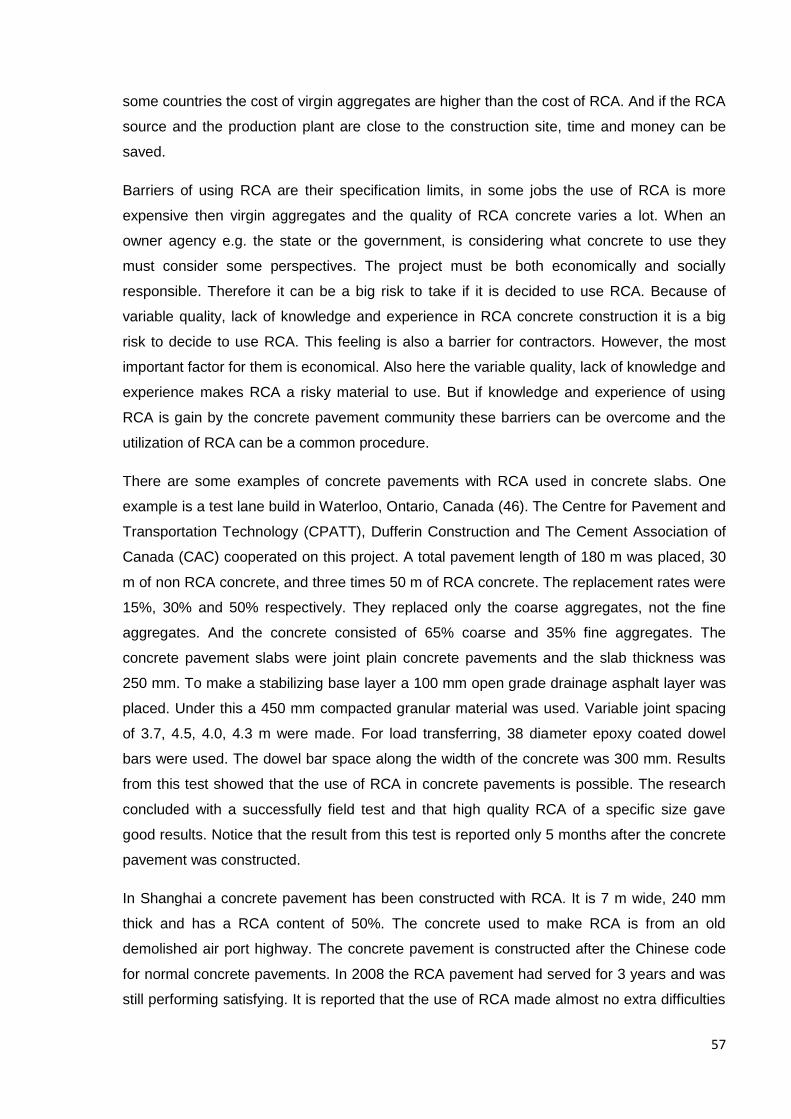
57
some countries the cost of virgin aggregates are higher than the cost of RCA. And if the RCA
source and the production plant are close to the construction site, time and money can be
saved.
Barriers of using RCA are their specification limits, in some jobs the use of RCA is more
expensive then virgin aggregates and the quality of RCA concrete varies a lot. When an
owner agency e.g. the state or the government, is considering what concrete to use they
must consider some perspectives. The project must be both economically and socially
responsible. Therefore it can be a big risk to take if it is decided to use RCA. Because of
variable quality, lack of knowledge and experience in RCA concrete construction it is a big
risk to decide to use RCA. This feeling is also a barrier for contractors. However, the most
important factor for them is economical. Also here the variable quality, lack of knowledge and
experience makes RCA a risky material to use. But if knowledge and experience of using
RCA is gain by the concrete pavement community these barriers can be overcome and the
utilization of RCA can be a common procedure.
There are some examples of concrete pavements with RCA used in concrete slabs. One
example is a test lane build in Waterloo, Ontario, Canada (46). The Centre for Pavement and
Transportation Technology (CPATT), Dufferin Construction and The Cement Association of
Canada (CAC) cooperated on this project. A total pavement length of 180 m was placed, 30
m of non RCA concrete, and three times 50 m of RCA concrete. The replacement rates were
15%, 30% and 50% respectively. They replaced only the coarse aggregates, not the fine
aggregates. And the concrete consisted of 65% coarse and 35% fine aggregates. The
concrete pavement slabs were joint plain concrete pavements and the slab thickness was
250 mm. To make a stabilizing base layer a 100 mm open grade drainage asphalt layer was
placed. Under this a 450 mm compacted granular material was used. Variable joint spacing
of 3.7, 4.5, 4.0, 4.3 m were made. For load transferring, 38 diameter epoxy coated dowel
bars were used. The dowel bar space along the width of the concrete was 300 mm. Results
from this test showed that the use of RCA in concrete pavements is possible. The research
concluded with a successfully field test and that high quality RCA of a specific size gave
good results. Notice that the result from this test is reported only 5 months after the concrete
pavement was constructed.
In Shanghai a concrete pavement has been constructed with RCA. It is 7 m wide, 240 mm
thick and has a RCA content of 50%. The concrete used to make RCA is from an old
demolished air port highway. The concrete pavement is constructed after the Chinese code
for normal concrete pavements. In 2008 the RCA pavement had served for 3 years and was
still performing satisfying. It is reported that the use of RCA made almost no extra difficulties
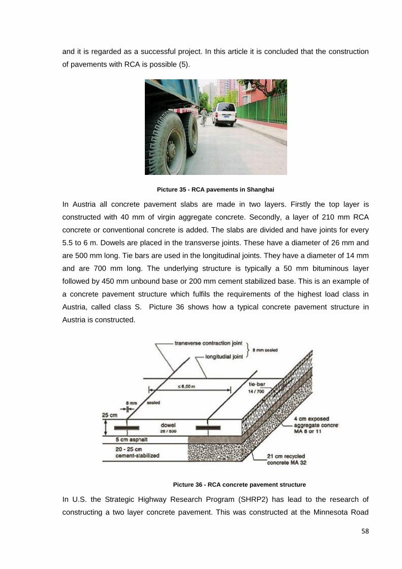
58
and it is regarded as a successful project. In this article it is concluded that the construction
of pavements with RCA is possible (5).
Picture 35 - RCA pavements in Shanghai
In Austria all concrete pavement slabs are made in two layers. Firstly the top layer is
constructed with 40 mm of virgin aggregate concrete. Secondly, a layer of 210 mm RCA
concrete or conventional concrete is added. The slabs are divided and have joints for every
5.5 to 6 m. Dowels are placed in the transverse joints. These have a diameter of 26 mm and
are 500 mm long. Tie bars are used in the longitudinal joints. They have a diameter of 14 mm
and are 700 mm long. The underlying structure is typically a 50 mm bituminous layer
followed by 450 mm unbound base or 200 mm cement stabilized base. This is an example of
a concrete pavement structure which fulfils the requirements of the highest load class in
Austria, called class S. Picture 36 shows how a typical concrete pavement structure in
Austria is constructed.
Picture 36 - RCA concrete pavement structure
In U.S. the Strategic Highway Research Program (SHRP2) has lead to the research of
constructing a two layer concrete pavement. This was constructed at the Minnesota Road
59
Research Facility. It is not usual to construct two lift pavements in U.S. So this was a test to
see how this technique performed in U.S. The goal for this project was to understand this
type of pavement technique, which is more common in Europe. Because of the possibilities
of utilizing RCA in these concrete structures the research done here is regarded important.
The target of this research was to design and construct a new composite pavement system
and to determine the behaviour, the critical material and the performance parameters. The
concrete pavement structure was constructed with the upper concrete layer consisting of
high strength Portland cement and 15% fly ash. The aggregate in the upper layer was
crushed granite. In the lower concrete layer low strength Portland cement and 60% fly ash
was used. Aggregates in this layer consists of 50% RCA and 50% Mn/DOT Class 5. The
maximum aggregate sizes were 31.75 mm. A 200 mm unbound base were used as an
underlying layer. Below this was the subgrade. It consisted of clay. The joint spacing was 4.5
m. Dowel bars with a diameter of 31.75 mm were placed in the transverse joints, at mid
depth. To reinforce longitudinal joints, tie bars with a diameter of 12.5 mm were used.
The construction of the pavement began 28th of April and was concluded the 10th of May.
Before the work started some concerns were formulated. A critical point when constructing
this type of two layer concrete pavements is that the upper layer needs to be placed only 15
to 90 minutes after the first layer is placed. So it is important that the delivery of concrete is
on time. It is also important to establish a complete planning programme in detail. Another
effect to be aware of is the different shrinkage, rates of hydration and the compound problem
of bounding at the interface. Those are even more critical when this type of concrete
mixtures is applied, because RCA concrete do not act the same way as normal concrete.
Another concern was the batching plant. When this pavement technique is applied in Europe
it is common to use two different batching plants. This is because the second concrete layer
has to be placed a short time after the first. However in this project it was only used one
concrete supplier.
When construction started the weather was not ideal. High temperatures and a lot of wind
combined with concrete mixes that did not have a consistent workability, made the
construction difficult. The temperature and the wind lead to a faster setting. And the
workability varied with a slump value from 6 mm to 70 mm. The target slump value was 25
mm. It is believed that the reason for this was the concrete supplier inexperience with fly ash.
Another problem was the RCA stockpile. This was supposed to be saturated. However it is
believed that in some periods the stockpile was allowed to dry.
Nevertheless, it can be settled form this project that RCA was a viable material to use as
coarse aggregate for the lower lift. This is provided the RCA comes from a known source,
60
fine aggregates are excluded and the stockpile was properly maintained. It is believed that if
the supplier had more experience with fly ash and RCA the project would have been more
successful. And if the project had been planned better, the mix delays would not have been a
problem.
The utilization of RCA in concrete pavements has a great potential. Concrete pavements
have a huge construction volume. And the aggregate size is large. It seems like the
pavement industries, states and government are very interested in making RCA a common
material in pavement constructions. E.g. the Technology Deployment Plan with a ten years
goal of making RCA a good alternative to natural aggregates. Not all of the barriers of RCA
concrete have to do with its properties. If knowledge and experience about RCA is gain it will
be possible to overcome the barriers. All the examples, like the test lane in Waterloo, the
pavement in Shanghai, and pavement constructions in Austria etc. proves that a
development is ongoing. Developments like these helps RCA concrete pavements to
become a normal procedure in road construction industries. However it seems like there is a
long way to go before reaching the goal.
Table of suggested possibilities for utilization of RCA concrete in concrete pavements
Alternative No. Alternative No.1
Alternative No.2
Solution Joint Palin Concrete pavements. Using RCA in the underlying layer of two lift concrete pavements.
Reason This is the most common pavement type, and the best type for controlling cracks. It should be possible. Especially when RCA mixture designs are developing towards conventional concrete properties. Another reason is the interest in utilization shown by governments. E.g. the Technology Deployment Plan in the United States.
The underlying layer of two lift concrete pavements is usually a concrete of a lower quality than the overlying surface layer. This makes it a good possibility for utilisation of RCA. It is already a practice to use it in some European countries. E.g. Austria and Germany.
61
Conclusion
Research shows that concrete with RCA is negatively affected. However research also
shows that if the concrete mixture proportioning, setting and curing is controlled the RCA
concrete can be created with similar properties as NAC. And also the quality and amount of
RCA is an important factor for how the concrete is affected. With a low replacement rate of
up to 20 or 30% and the use of high quality RCA the concrete properties is not severely
affected. After my opinion this leads to possibilities of utilizing RCA concrete on both the
construction sites and in prefabrication processes.
The result from using the EMV method in a worksheet shows that the environmental effects
are positive. Not only preserving natural recourses and recycling waste concrete, but also
reducing the CO2 emission from the cement industry is possible. This is because the EMV
method gives a lower amount of needed cement to mix the concrete.
By using a proposed equation for reduction of compressive strength in RCA concrete the
calculation of resistance in the beam in my example was little effected. The reason is that
compressive strength is not the most important factor when calculating moment capacity in a
reinforced concrete beam. The crucial factor is the steel reinforcement.
Researching non structural possibilities has been interesting. I think RCA concrete can be
used in a variety of construction application. Personally I think the utilization of RCA in
concrete pavements has the greatest potential. The background for this belief is the huge
interest for using RCA in concrete pavements. It is satisfying to see the effort which is being
applied to utilizing of concrete waste. And it is good to see that there are products on the
marked which incorporates RCA. It is also nice to have discovered that some countries
already have developed specifications for RCA concrete, and that assessment systems gives
RCA high credits. However further research is needed to get knowledge about how RCA
concrete will perform in the suggested non structural applications in this dissertation. And
experience of using the material on construction sites and in prefabrication plant is needed if
RCA is to become a common and approved alternative to natural concrete aggregates.
62
Acknowledgement First and foremost I would like to thank my professor Enrique David Llácer. He has given my
guidance and advice throughout this project. I would also like to thank him for ideas and
inspiration which helped my write this thesis.
I would like to express my gratitude to the members of the jury. I would like to thank them for
taking the time to read and evaluate my text. My sincere thanks also go to the international
office at UPV for arranging this academical project for exchange students.
Last but not least, I wish to thank my fellow students in this course for being at the tutorials
and listening to my presentations. And a special thanks to my friend and fellow student from
Bergen University collage, Harald Bjørntvedt. He has given my motivation and inspiration
throughout this project.
List of annexes
Annex 1 – beam calculations
Annex 2 – Example of the EMV method
Annex 3 – A summarizing table of non structural possibilities

63
References
1. Construction materials recycling association. ConcreteRecycling.org. [Online] 2006 - 2013. [Cited:
April 18, 2013.] http://www.concreterecycling.org/how.html.
2. Mapei. Re-Con Zero. [Online] [Cited: may 13, 2013.] http://www.mapei.com/adv/NO/re-
con_zero/.
3. Marie, I. and Quiasrawi, H. Closed - loop recycling of recycled concrete aggregates. Jordan :
Elsevier Ltd, 2012.
4. Thomas, C., et al. Durability of recycled aggregate concrete. Spain : Elsevier Ltd., 2012.
5. Li, Xuping. Recycling and reuse of waste in concrete in China part II. Structural behaviour of
recycled aggregate concrete and engineering applications. Zhejiang : Elsevier B.V, 2008.
6. Etkin Johnson Group. Enterprise Park at Stapleton. [Online] 2012. [Cited: April 18, 2013.]
http://www.etkinjohnson-stapleton.com/index.php#.
7. Building and Construction Authority, Singapore. Sustainable Construction A guide on Concrete
Usage Index. Singapore : Building and Construction Authority, Singapore, 2012.
8. Concrete technology today. www.cement.org/cct. [Online] 2002. [Cited: May 11, 2013.]
http://www.cement.org/pdf_files/ct022.pdf.
9. Mehta, P. Kumar. Reducing the environmental impact of concrete. Berkeley,U.S.A. : Concrete
international, 2001.
10. Xu, T., Galama, T. and Sathaye, J. Reducing carbon fotprint in cement material making:
Characterizing cost of conserved energy and reduced carbon emisions. Berkely, U.S. : Elsevier B.V.,
2013.
11. Choi, W-C and Yun, H-D. Compressive behavior of reinforced concrete columns with recycled
aggregate under uniaxial loading. USA and Korea : Elsevier Ltd, 2012.
12. Jiménez, C., et al. Equvilent Mortar Volume (EMV) method for proportioning recycled aggregate
concrete: Validation under the Spanish context and its adaption to Bolomey methodology for concrete
proportioning. Barcelona, Spain : Materiales de Construcción, 2012.
13. Schubert, S., et al. Recycled aggregate concrete: Experimental Shear Resistance of Slabs Without
Shear Reinforcement. Switzerland : Elsevier Ltd, 2012.
14. Fathifazl, G., et al. Shear capasity evaluation of steel reinforced recycled concrete (RRC) beams.
Canada : Elsevier Ltd, 2010.
15. Isgor, O.B, et al. Durability of recycled aggregate concrete designed with equivalent mortar
volume method. Canada : Elsevier, 2009.
16. McGovern, Martin. Going with the Flow. Concrete technology today. July 2002.
64
17. Fathifazl, G., et al. Creep and drying shrinkage characteristics of concreteproduced with coarse
recycled aggregate. Cement & Concrete Composits. 2011.
18. Premier Mortars. Premier Mortars - Ready to use mortars screeds and renders. [Online] 2013.
[Cited: May 11, 2013.] http://www.premiermortars.co.uk/concrete/ready-mixed-concrete#.
19. Cement Concrete and Aggregates Australia. Use of recycled aggregates in Construction. [Online]
2008. [Cited: May 12, 2013.] http://www.concrete.net.au/publications/pdf/RecycledAggregates.pdf.
20. Garber, S., et al. A Technology Deployment Plan for the Use of Recycled Concrete Aggregates in
Concrete Paving Mixture. s.l. : Iowa State University, 2011.
21. Skytterholm, Ole and Mehus, Jacob. Veileder for bruk av resirkulert tilslag. Norway : Øko-bygg,
2002.
22. Norsk Betongforening. Materialgjenvinning av betong og murverk for betongproduksjon (2003)
Norsk utgave . Norway : Norsk Betongforening, 2003.
23. New Mixture Proportioning Method for Concrete Made with Coarse Recycled Concrete
Aggregates. G. Fathifazl; A. Abbas; A. G. Razaqpur; O. B. Isgor; B. Fournier; and S. Foo. 2009, Journal
of aterials in Civil engineering.
24. Norsk Betongforening. CO2 - Utslipp - Sement og betong - Utfordringer og perspektiver. Norway :
Norsk Betongforening, 2008.
25. Portland Cement Association . Portland Cement Association . [Online] 2013. [Cited: May 10,
2013.] http://www.cement.org/tech/faq_recycled.asp.
26. National precast concrete association Australia. National precast concrete association Australia.
[Online] [Cited: May 10, 2013.]
http://www.npcaa.com.au/members_products/buildings/walls/sandwich_panels/.
27. Sintef Byggforsk. Betongelementer i fasader. Norway : Sintef Byggforsk, 1994.
28. Owens Corning. commercial.owenscorning.com. [Online] 2007. [Cited: may 11, 2010.]
http://commercial.owenscorning.com/assets/0/144/172/174/ab82355e-a751-4980-953b-
3ffbafde01f7.pdf.
29. Sintef Byggforsk. Sintef Byggforsk Kunnskapssystemer. [Online] 1994. [Cited: may 11, 2013.]
http://bks.byggforsk.no/DocumentView.aspx?sectionId=2&documentId=367.
30. AltusGroup. www.altusprecast.com. [Online] 2013. [Cited: May 15, 2013.]
http://altusprecast.com/products/c-grid/.
31. Mapei. www.mapei.com. [Online] 2005. [Cited: May 13, 2013.]
http://www.mapei.com/public/NO/products/329_ElastocolorPaint_no.pdf.
32. KÖSTER. www.koester.eu. [Online] March 1, 2013. [Cited: May 14, 2013.]
http://www.koester.eu/files/de_en/3.03015-21.pdf.
65
33. SISMO Building Technology. www.sismo.eu. [Online] [Cited: June 4, 2013.]
http://www.sismo.eu/site/concept.asp?v=en.
34. Tricon Precast Limited. Tricon Precast Limited. [Online] 2013. [Cited: May 12, 2013.]
http://www.triconprecast.com/precast_sound_wall_systems.htm.
35. National Precast Concrete Association. Precast concrete absorptive sound walls. United States of
America and Canada : National Precast concrete Association.
36. M. Metha, W. Scarboough, D. Armpriest. Exterior Wall Cladding - II. Buliding Construction:
Principles, Materials, % Systems. s.l. : Pearson Higher Ed USA, 2011, pp. 638 - 685.
37. Metal Stud Crete. www.metalcrete.com. [Online] 2008. [Cited: May 16, 2013.]
http://www.metalcrete.com/msc_system.html.
38. Sintef byggforsk. Murverk. Materialer, typer og egenskaper. s.l. : Sintef Byggforsk
Kunskapsystemer, 2011.
39. Swiss Resource Centre and Consultancies for Development. Concrete Blocks.
40. CEMEX READYBLOCK. 2000 Solid Dense Readyblock. s.l. : CEMEX READYBLOCK, 2003.
41. Readyblock. www.cemex.co.uk/readyblock. [Online] 2012. [Cited: may 27, 2013.]
http://www.cemex.co.uk/Userfiles/datasheets/masonary-ready-block-wallchart.pdf.
42. Barbour Product Search . Barbour Product Search The fastest route to the right product . [Online]
Septembre 7, 2007. [Cited: May 28, 2013.] http://www.barbourproductsearch.info/raf-syerston-
newark-news017621.html.
43. Aggregates Industries. www.greenspec.co.uk. [Online] 2013. [Cited: May 28, 2013.]
http://www.greenspec.co.uk/products/blocks/masterblock-enviroblock/.
44. Origon State University. [Online] [Cited: june 3, 2013.]
http://classes.engr.oregonstate.edu/cce/winter2012/ce492/Modules/02_pavement_types/02-
6_body.htm.
45. Federal Highway Administration. Office of internationale Programs. [Online] May 22, 2013.
[Cited: May 31, 2013.] http://international.fhwa.dot.gov/pubs/pl07027/llcp_07_03.cfm.
46. Smith, James T., et al. Coarse Recycled Aggregate Concrete Pavements - Design, Instrumentation,
and Performance. s.l. : Recycled Materials and Recycling Process for Sustainable Infrastructure
Session of the 2008 Annual Conference of the Transportation Association of Canada, 2008.
47. Norges Geologiske Undersøkelse. Norges Geologiske Undersøkelse. [Online] 2012. [Cited: April
29, 2013.] http://www.ngu.no/no/hm/Georessurser/Sand-grus-og-pukk/Ressursknapphet---
alternative-materialer/.
48. Marton, Ingun. Byggemiljø. [Online] 2008. [Cited: May 12, 2013.]
http://www.byggemiljo.no/category.php/category/Resirkulert%20tilslag/?categoryID=332.

66
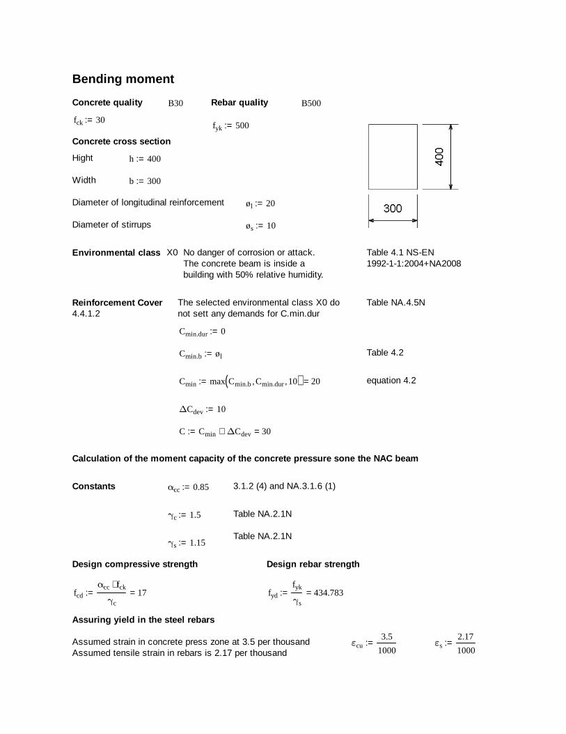
Bending moment
Concrete quality B30 Rebar quality B500
fck 30:=fyk 500:=
Concrete cross section
Hight h 400:=
Width b 300:=
Diameter of longitudinal reinforcement øl 20:=
Diameter of stirrups øs 10:=
Environmental class X0 No danger of corrosion or attack.The concrete beam is inside abuilding with 50% relative humidity.
Table 4.1 NS-EN1992-1-1:2004+NA2008
Reinforcement Cover The selected environmental class X0 donot sett any demands for C.min.dur
Table NA.4.5N4.4.1.2
Cmin.dur 0:=
Cmin.b øl:= Table 4.2
Cmin max Cmin.b Cmin.dur, 10, ( ) 20=:= equation 4.2
∆Cdev 10:=
C Cmin ∆Cdev+ 30=:=
Calculation of the moment capacity of the concrete pressure sone the NAC beam
Constants αcc 0.85:= 3.1.2 (4) and NA.3.1.6 (1)
γc 1.5:= Table NA.2.1N
Table NA.2.1Nγs 1.15:=
Design compressive strength Design rebar strength
fcd
αcc fck⋅
γc
17=:= fyd
fyk
γs
434.783=:=
Assuring yield in the steel rebars
Assumed strain in concrete press zone at 3.5 per thousandAssumed tensile strain in rebars is 2.17 per thousand
εcu3.5
1000:= εs
2.17
1000:=
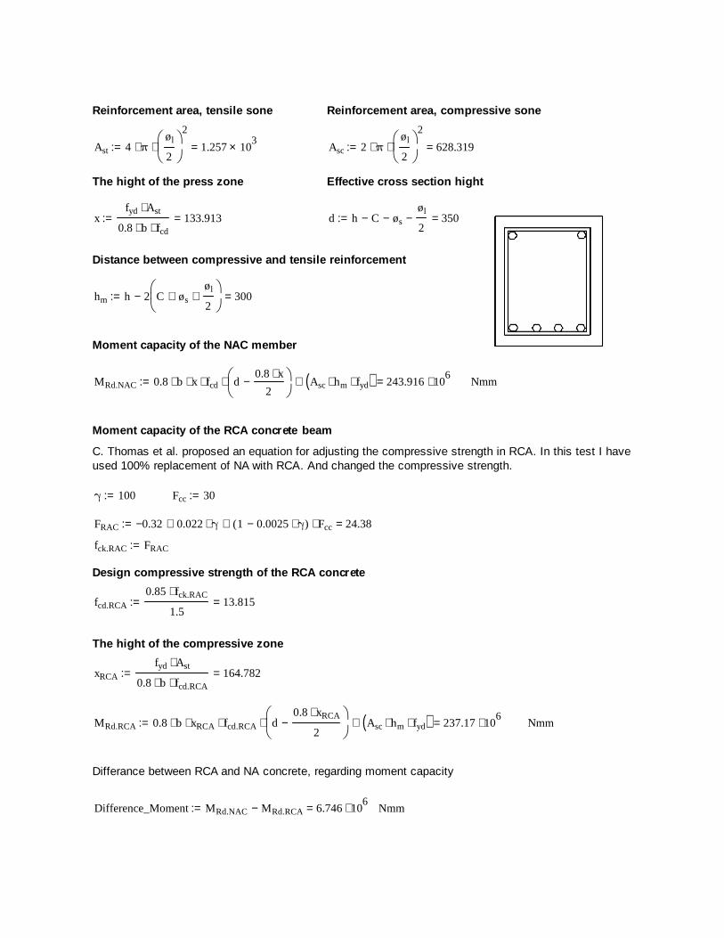
Reinforcement area, tensile sone Reinforcement area, compressive sone
Ast 4 π⋅øl
2
2
⋅ 1.257 103×=:= Asc 2 π⋅
øl
2
2
⋅ 628.319=:=
The hight of the press zone Effective cross section hight
xfyd Ast⋅
0.8 b⋅ fcd⋅133.913=:= d h C− øs−
øl
2− 350=:=
Distance between compressive and tensile reinforcement
hm h 2 C øs+øl
2+
− 300=:=
Moment capacity of the NAC member
MRd.NAC 0.8 b⋅ x⋅ fcd⋅ d0.8 x⋅
2−
⋅ Asc hm⋅ fyd⋅( )+ 243.916 106⋅=:= Nmm
Moment capacity of the RCA concrete beam
C. Thomas et al. proposed an equation for adjusting the compressive strength in RCA. In this test I haveused 100% replacement of NA with RCA. And changed the compressive strength.
γ 100:= Fcc 30:=
FRAC 0.32− 0.022 γ⋅+ 1 0.0025 γ⋅−( ) Fcc⋅+ 24.38=:=
fck.RAC FRAC:=
Design compressive strength of the RCA concrete
fcd.RCA
0.85 fck.RAC⋅
1.513.815=:=
The hight of the compressive zone
xRCA
fyd Ast⋅
0.8 b⋅ fcd.RCA⋅164.782=:=
MRd.RCA 0.8 b⋅ xRCA⋅ fcd.RCA⋅ d0.8 xRCA⋅
2−
⋅ Asc hm⋅ fyd⋅( )+ 237.17 106⋅=:= Nmm
Differance between RCA and NA concrete, regarding moment capacity
Difference_Moment MRd.NAC MRd.RCA− 6.746 106⋅=:= Nmm
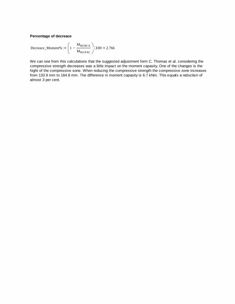
Percentage of decreace
Decreace_Moment% 1MRd.RCA
MRd.NAC−
100⋅ 2.766=:=
We can see from this calculations that the suggested adjustment form C. Thomas et al. considering thecompressive strength decreases was a little impact on the moment capasity. One of the changes is thehight of the compressive sone. When reducing the compressive strength the compressive zone increasesfrom 133.9 mm to 164.8 mm. The difference in moment capasity is 6.7 kNm. This equals a reduction ofalmost 3 per cent.
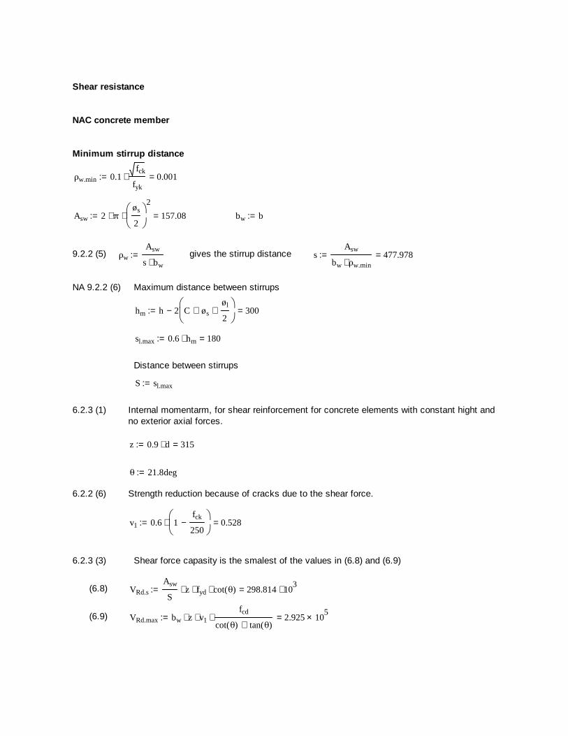
Shear resistance
NAC concrete member
Minimum stirrup distance
ρw.min 0.1fck
fyk⋅ 0.001=:=
Asw 2 π⋅øs
2
2
⋅ 157.08=:= bw b:=
9.2.2 (5) ρw
Asw
s bw⋅:= gives the stirrup distance s
Asw
bw ρw.min⋅477.978=:=
NA 9.2.2 (6) Maximum distance between stirrups
hm h 2 C øs+øl
2+
− 300=:=
sl.max 0.6 hm⋅ 180=:=
Distance between stirrups
S sl.max:=
6.2.3 (1) Internal momentarm, for shear reinforcement for concrete elements with constant hight andno exterior axial forces.
z 0.9 d⋅ 315=:=
θ 21.8deg:=
6.2.2 (6) Strength reduction because of cracks due to the shear force.
v1 0.6 1fck
250−
⋅ 0.528=:=
6.2.3 (3) Shear force capasity is the smalest of the values in (6.8) and (6.9)
(6.8) VRd.s
Asw
Sz⋅ fyd⋅ cot θ( )⋅ 298.814 10
3⋅=:=
(6.9) VRd.max bw z⋅ v1⋅fcd
cot θ( ) tan θ( )+⋅ 2.925 10
5×=:=
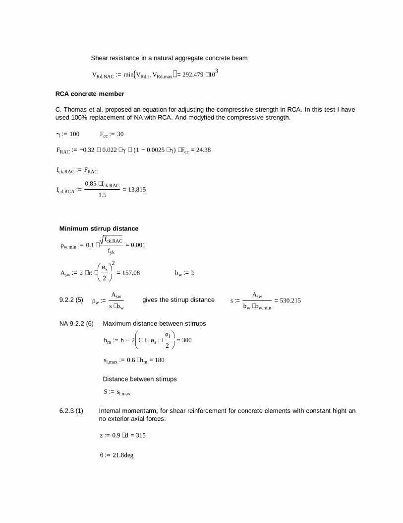
Shear resistance in a natural aggregate concrete beam
VRd.NAC min VRd.s VRd.max, ( ) 292.479 103⋅=:=
RCA concrete member
C. Thomas et al. proposed an equation for adjusting the compressive strength in RCA. In this test I haveused 100% replacement of NA with RCA. And modyfied the compressive strength.
γ 100:= Fcc 30:=
FRAC 0.32− 0.022 γ⋅+ 1 0.0025 γ⋅−( ) Fcc⋅+ 24.38=:=
fck.RAC FRAC:=
fcd.RCA
0.85 fck.RAC⋅
1.513.815=:=
Minimum stirrup distance
ρw.min 0.1fck.RAC
fyk⋅ 0.001=:=
Asw 2 π⋅øs
2
2
⋅ 157.08=:= bw b:=
9.2.2 (5) ρw
Asw
s bw⋅:= gives the stirrup distance s
Asw
bw ρw.min⋅530.215=:=
NA 9.2.2 (6) Maximum distance between stirrups
hm h 2 C øs+øl
2+
− 300=:=
sl.max 0.6 hm⋅ 180=:=
Distance between stirrups
S sl.max:=
6.2.3 (1) Internal momentarm, for shear reinforcement for concrete elements with constant hight andno exterior axial forces.
z 0.9 d⋅ 315=:=
θ 21.8deg:=
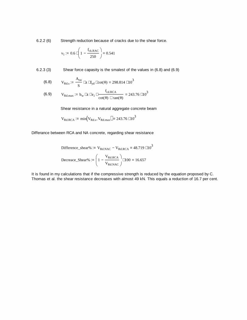
6.2.2 (6) Strength reduction because of cracks due to the shear force.
v1 0.6 1fck.RAC
250−
⋅ 0.541=:=
6.2.3 (3) Shear force capasity is the smalest of the values in (6.8) and (6.9)
(6.8) VRd.s
Asw
Sz⋅ fyd⋅ cot θ( )⋅ 298.814 10
3⋅=:=
(6.9) VRd.max bw z⋅ v1⋅fcd.RCA
cot θ( ) tan θ( )+⋅ 243.76 10
3⋅=:=
Shear resistance in a natural aggregate concrete beam
VRd.RCA min VRd.s VRd.max, ( ) 243.76 103⋅=:=
Differance between RCA and NA concrete, regarding shear resistance
Difference_shear% VRd.NAC VRd.RCA− 48.719 103⋅=:=
Decreace_Shear% 1VRd.RCA
VRd.NAC
−
100⋅ 16.657=:=
It is found in my calculations that if the compressive strength is reduced by the equation proposed by C.Thomas et al. the shear resistance decreases with almost 49 kN. This equals a reduction of 16.7 per cent.
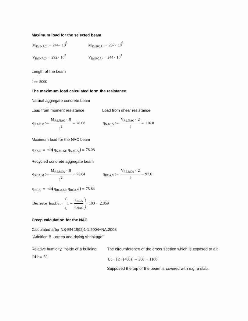
Maximum load for the selected beam.
MRd.NAC 244 106
MRd.RCA 237 106
VRd.NAC 292 103
VRd.RCA 244 103
Length of the beam
l 5000
The maximum load calculated form the resistance.
Natural aggregate concrete beam
Load from moment resistance Load from shear resistance
qNAC.M
MRd.NAC 8
l2
78.08 qNAC.V
VRd.NAC 2
l116.8
Maximum load for the NAC beam
qNAC min qNAC.M qNAC.V 78.08
Recycled concrete aggregate beam
qRCA.M
MRd.RCA 8
l2
75.84 qRCA.V
VRd.RCA 2
l97.6
qRCA min qRCA.M qRCA.V 75.84
Decreace_load% 1qRCA
qNAC
100 2.869
Creep calculation for the NAC
Calculated after NS-EN 1992-1-1:2004+NA:2008
"Addition B - creep and drying shrinkage"
Relative humidity, inside of a building The circumference of the cross section which is exposed to air.
RH 50U 2 400( )[ ] 300 1100
Supposed the top of the beam is covered with e.g. a slab.
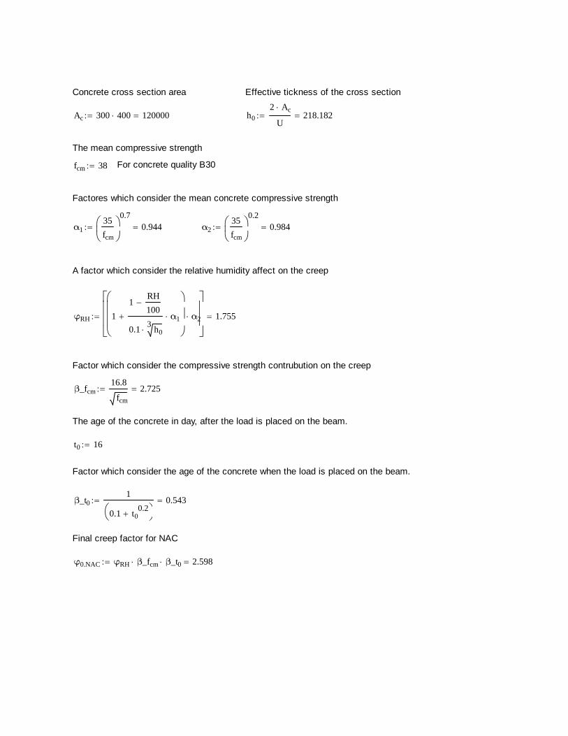
Concrete cross section area Effective tickness of the cross section
Ac 300 400 120000 h0
2 Ac
U218.182
The mean compressive strength
fcm 38 For concrete quality B30
Factores which consider the mean concrete compressive strength
α135
fcm
0.7
0.944 α235
fcm
0.2
0.984
A factor which consider the relative humidity affect on the creep
φRH 1
1RH
100
0.13
h0α1
α2
1.755
Factor which consider the compressive strength contrubution on the creep
β_fcm16.8
fcm
2.725
The age of the concrete in day, after the load is placed on the beam.
t0 16
Factor which consider the age of the concrete when the load is placed on the beam.
β_t01
0.1 t00.2
0.543
Final creep factor for NAC
φ0.NAC φRH β_fcm β_t0 2.598
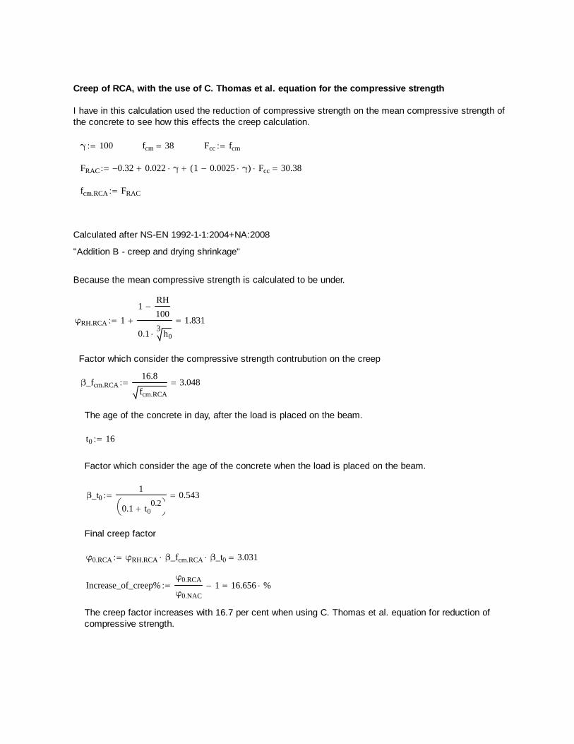
Creep of RCA, with the use of C. Thomas et al. equation for the compressive strength
I have in this calculation used the reduction of compressive strength on the mean compressive strength ofthe concrete to see how this effects the creep calculation.
γ 100 fcm 38 Fcc fcm
FRAC 0.32 0.022 γ 1 0.0025 γ( ) Fcc 30.38
fcm.RCA FRAC
Calculated after NS-EN 1992-1-1:2004+NA:2008
"Addition B - creep and drying shrinkage"
Because the mean compressive strength is calculated to be under.
φRH.RCA 1
1RH
100
0.13
h0 1.831
Factor which consider the compressive strength contrubution on the creep
β_fcm.RCA16.8
fcm.RCA
3.048
The age of the concrete in day, after the load is placed on the beam.
t0 16
Factor which consider the age of the concrete when the load is placed on the beam.
β_t01
0.1 t00.2
0.543
Final creep factor
φ0.RCA φRH.RCA β_fcm.RCA β_t0 3.031
Increase_of_creep%φ0.RCA
φ0.NAC
1 16.656 %
The creep factor increases with 16.7 per cent when using C. Thomas et al. equation for reduction ofcompressive strength.
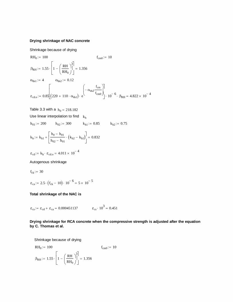
Drying shrinkage of NAC concrete
Shrinkage because of drying
RH0 100 fcm0 10
βRH 1.55 1RH
RH0
3
1.356
αds1 4 αds2 0.12
εcd.o 0.85 220 110 αds1 e
αds2fcm
fcm0
10
6 βRH 4.822 10
4
Table 3.3 with a h0 218.182
Use linear interpolation to find kh
h01 200 h02 300 kh1 0.85 kh2 0.75
kh kh1
h0 h01
h02 h01kh2 kh1
0.832
εcd kh εcd.o 4.011 104
Autogenous shrinkage
fck 30
εca 2.5 fck 10 106
5 105
Total shrinkage of the NAC is
εcs εcd εca 0.000451137 εcs 103
0.451
Drying shrinkage for RCA concrete when the compressive strength is adjusted after the equationby C. Thomas et al.
Shrinkage because of drying
RH0 100 fcm0 10
βRH 1.55 1RH
RH0
3
1.356
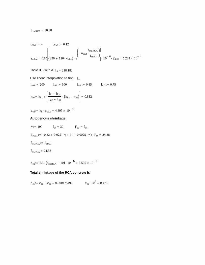
fcm.RCA 30.38
αds1 4 αds2 0.12
εcd.o 0.85 220 110 αds1 e
αds2fcm.RCA
fcm0
10
6 βRH 5.284 10
4
Table 3.3 with a h0 218.182
Use linear interpolation to find kh
h01 200 h02 300 kh1 0.85 kh2 0.75
kh kh1
h0 h01
h02 h01kh2 kh1
0.832
εcd kh εcd.o 4.395 104
Autogenous shrinkage
γ 100 fck 30 Fcc fck
FRAC 0.32 0.022 γ 1 0.0025 γ( ) Fcc 24.38
fck.RCA FRAC
fck.RCA 24.38
εca 2.5 fck.RCA 10 106
3.595 105
Total shrinkage of the RCA concrete is
εcs εcd εca 0.000475496 εcs 103
0.475

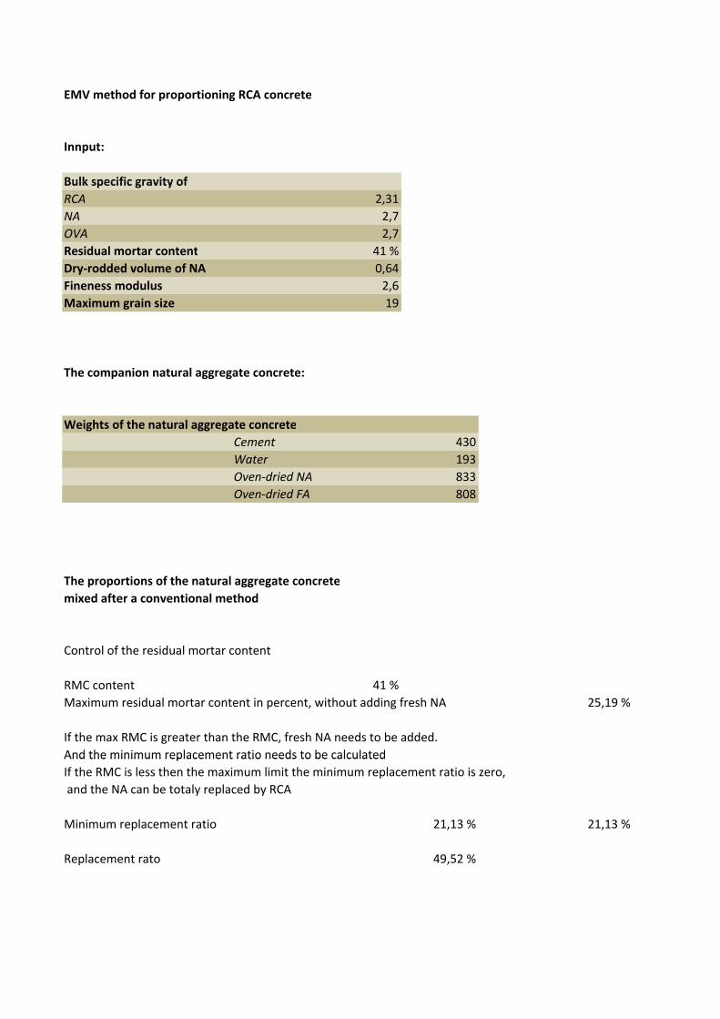
EMV method for proportioning RCA concrete
Innput:
Bulk specific gravity ofBulk specific gravity of
RCA 2,31
NA 2,7
OVA 2,7
Residual mortar content 41 %
Dry-rodded volume of NA 0,64
Fineness modulus 2,6
Maximum grain size 19Maximum grain size 19
The companion natural aggregate concrete:
Weights of the natural aggregate concrete
430
193
Oven-dried NA 833
Oven-dried FA 808
Cement
Water
The proportions of the natural aggregate concrete
mixed after a conventional method
Control of the residual mortar contentControl of the residual mortar content
RMC content 41 %
Maximum residual mortar content in percent, without adding fresh NA 25,19 %
If the max RMC is greater than the RMC, fresh NA needs to be added.
And the minimum replacement ratio needs to be calculatedAnd the minimum replacement ratio needs to be calculated
If the RMC is less then the maximum limit the minimum replacement ratio is zero,
and the NA can be totaly replaced by RCA
Minimum replacement ratio 21,13 % 21,13 %
Replacement rato 49,52 %
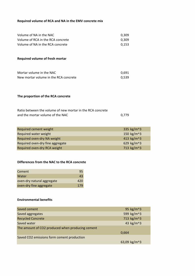
Required volume of RCA and NA in the EMV concrete mix
Volume of NA in the NAC 0,309
Volume of RCA in the RCA concrete 0,309
Volume of NA in the RCA concrete 0,153
Required volume of fresh mortar
Mortar volume in the NAC 0,691
New mortar volume in the RCA concrete 0,539
The proportion of the RCA concrete
Ratio between the volume of new mortar in the RCA concrete Ratio between the volume of new mortar in the RCA concrete
and the mortar volume of the NAC 0,779
Required cement weight 335 kg/m^3
Required water weight 150 kg/m^3
Required oven-dry NA weight 413 kg/m^3
Required oven-dry fine aggregate 629 kg/m^3Required oven-dry fine aggregate 629 kg/m^3
Required oven-dry RCA weight 713 kg/m^3
Differences from the NAC to the RCA concrete
Cement 95
Water 43Water 43
oven-dry natural aggregate 420
oven-dry fine aggregate 179
Environmental benefits
Saved cement 95 kg/m^3
Saved aggregates 599 kg/m^3
Recycled Concrete 713 kg/m^3
Saved water 43 kg/m^3
The amount of CO2 produced when producing cement
0,664
Saved CO2 emissions form cement productionSaved CO2 emissions form cement production
63,09 kg/m^3
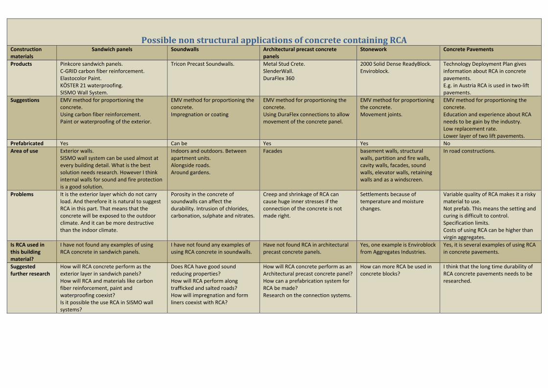
PossiblenonstructuralapplicationsofconcretecontainingRCAConstruction materials
Sandwich panels Soundwalls Architectural precast concrete panels
Stonework Concrete Pavements
Products Pinkcore sandwich panels. C‐GRID carbon fiber reinforcement. Elastocolor Paint. KÖSTER 21 waterproofing. SISMO Wall System.
Tricon Precast Soundwalls. Metal Stud Crete. SlenderWall. DuraFlex 360
2000 Solid Dense ReadyBlock. Enviroblock.
Technology Deployment Plan gives information about RCA in concrete pavements. E.g. in Austria RCA is used in two‐lift pavements.
Suggestions EMV method for proportioning the concrete. Using carbon fiber reinforcement. Paint or waterproofing of the exterior.
EMV method for proportioning the concrete. Impregnation or coating
EMV method for proportioning the concrete. Using DuraFlex connections to allow movement of the concrete panel.
EMV method for proportioning the concrete. Movement joints.
EMV method for proportioning the concrete. Education and experience about RCA needs to be gain by the industry. Low replacement rate. Lower layer of two lift pavements.
Prefabricated Yes Can be Yes Yes No Area of use Exterior walls.
SISMO wall system can be used almost at every building detail. What is the best solution needs research. However I think internal walls for sound and fire protection is a good solution.
Indoors and outdoors. Between apartment units. Alongside roads. Around gardens.
Facades basement walls, structural walls, partition and fire walls, cavity walls, facades, sound walls, elevator walls, retaining walls and as a windscreen.
In road constructions.
Problems It is the exterior layer which do not carry load. And therefore it is natural to suggest RCA in this part. That means that the concrete will be exposed to the outdoor climate. And it can be more destructive than the indoor climate.
Porosity in the concrete of soundwalls can affect the durability. Intrusion of chlorides, carbonation, sulphate and nitrates.
Creep and shrinkage of RCA can cause huge inner stresses if the connection of the concrete is not made right.
Settlements because of temperature and moisture changes.
Variable quality of RCA makes it a risky material to use. Not prefab. This means the setting and curing is difficult to control. Specification limits. Costs of using RCA can be higher than virgin aggregates.
Is RCA used in this building material?
I have not found any examples of using RCA concrete in sandwich panels.
I have not found any examples of using RCA concrete in soundwalls.
Have not found RCA in architectural precast concrete panels.
Yes, one example is Enviroblock from Aggregates Industries.
Yes, it is several examples of using RCA in concrete pavements.
Suggested further research
How will RCA concrete perform as the exterior layer in sandwich panels? How will RCA and materials like carbon fiber reinforcement, paint and waterproofing coexist? Is it possible the use RCA in SISMO wall systems?
Does RCA have good sound reducing properties? How will RCA perform along trafficked and salted roads? How will impregnation and form liners coexist with RCA?
How will RCA concrete perform as an Architectural precast concrete panel? How can a prefabrication system for RCA be made? Research on the connection systems.
How can more RCA be used in concrete blocks?
I think that the long time durability of RCA concrete pavements needs to be researched.