Embed Size (px)
Citation preview

Use of Tire DerivedProducts (TDP) in
Roadway Construction
Matthew Oman, Primary AuthorBraun Intertec Corporation
July 2013Research Project
Final Report 2013-20

To request this document in an alternative format, call Bruce Lattu at 651-366-4718 or 1-800-657-3774 (Greater Minnesota); 711 or 1-800-627-3529 (Minnesota Relay). You may also send an e-mail to [email protected]. (Please request at least one week in advance).

Technical Report Documentation Page 1. Report No. 2. 3. Recipients Accession No. MN/RC 2013-20 4. Title and Subtitle 5. Report Date
Use of Tire Derived Products (TDP) in Roadway Construction June 2013 6.
7. Author(s) 8. Performing Organization Report No. Megan Hoppe and Matthew Oman 9. Performing Organization Name and Address 10. Project/Task/Work Unit No. Braun Intertec Corporation 1826 Buerkle Road St. Paul, Minnesota 55110
11. Contract (C) or Grant (G) No.
(c) 03598
12. Sponsoring Organization Name and Address 13. Type of Report and Period Covered Minnesota Department of Transportation 395 John Ireland Boulevard, MS 330 St. Paul, MN 55155
Final Report 14. Sponsoring Agency Code
15. Supplementary Notes http://www.lrrb.org/PDF/201320.pdf 16. Abstract (Limit: 250 words) Tire Derived Aggregate (TDA) is referred to in this report as rough shreds, shreds, and tire chips of various sizes. The potential uses discussed herein include TDA as lightweight fill, retaining wall backfill, insulation layer, drainage layer, and capillary moisture break. Other uses exist; however, they are beyond the scope of this report. This report summarizes the results of numerous studies regarding the environmental concerns of using TDA both above and below the ground water table. The summary provides general observations based on the literature review performed, comments on the current state of the practice regarding the use of TDA for highway applications, and information on additional resources.
17. Document Analysis/Descriptors 18. Availability Statement tire derived aggregate lightweight fill TDA roadway construction shreds geotechnical use tire chips
No restrictions. Document available from: National Technical Information Services, Alexandria, Virginia 22312
19. Security Class (this report) 20. Security Class (this page) 21. No. of Pages 22. Price Unclassified Unclassified 58
Use of Tire Derived Products (TDP) in Roadway Construction
Final Report
Principal Investigator Matthew S. Oman, P.E.
Braun Intertec Corporation
Co-Principal Investigator Jeffrey Gebhard, P.E.
Braun Intertec Corporation
Report Prepared By Megan J.L. Hoppe, P.E.
Braun Intertec Corporation
June 2013
Published by
Minnesota Department of Transportation Research Services Section
395 John Ireland Boulevard St. Paul, MN 55155-1899
This report represents the results of research conducted by the author and does not necessarily represent the views of policies of the Minnesota Department of Transportation or Braun Intertec. This report does not contain a standard or specified technique.
The authors, the Minnesota Department of Transportation, and Braun Intertec do not endorse products or manufacturers. Any trade or manufacturers’ names that may appear herein do so solely because they are considered essential to this report
ACKNOWLEGMENTS The authors thank the following members of the Technical Advisory Panel (TAP) for their participation in this project and their valuable input and assistance:
• Blake Nelson, MnDOT Technical Liaison • Shirlee Sherkow, MnDOT Research Services, Project Coordinator • Other Members
o MnDOT –Tim Andersen, Pavement Design Engineer and Harold Bottolfson, Air & Noise Specialist
o MPCA – Dan Vleck, Solid Waste Engineer o Industry – Rahni Bahr, General Manager-Savage, Liberty Tire Recycling; Monte Nemi,
CEO, First State Tire Recycling; and Tammy Schmitz, Marketing and Public Relations, First State Tire Recycling
The authors thank Glenn Engstrom and Alan Rindels of MnDOT for helping initiate this study. The authors thank Jim Byerly, Marilee Tuite, and Danae Ostroot of the MnDOT Library for locating and providing many of the resources utilized in the preparation of this report. The authors also thank Jennifer Force, Jeffrey Casmer and Debashis Sikdar, Ph.D., P.E. of Braun Intertec for providing reviews of some of the articles sited herein.
TABLE OF CONTENTS
CHAPTER 1: BACKGROUND .................................................................................................................................... 1 1.1 Problem Statement ......................................................................................................................................... 1 1.2 Objective ........................................................................................................................................................ 1 1.3 Scope ............................................................................................................................................................. 1
CHAPTER 2: HISTORICAL PERSPECTIVE ............................................................................................................. 2 2.1 The Early Years ............................................................................................................................................. 2
2.1.1 1960-1980 .............................................................................................................................................. 2 2.1.2 1980-1994 .............................................................................................................................................. 2
2.2 1994 to Present .............................................................................................................................................. 3 2.2.1 Exothermic Reactions ............................................................................................................................ 3 2.2.2 ASTM D6270 ........................................................................................................................................ 3 2.2.3 MnDOT ................................................................................................................................................. 5 2.2.4 Minnesota Regulations .......................................................................................................................... 6
CHAPTER 3: HIGHWAY APPLICATIONS .............................................................................................................. 7 3.1 Uses ............................................................................................................................................................... 7 3.2 Lightweight Fill ............................................................................................................................................. 7 3.3 Retaining Wall Backfill ................................................................................................................................. 8 3.4 Insulation layer .............................................................................................................................................. 8 3.5 Drainage Layer .............................................................................................................................................. 8 3.6 Capillary Moisture Break .............................................................................................................................. 8
CHAPTER 4: TEST SECTIONS AND PROJECTS ................................................................................................... 10 4.1 Colorado ...................................................................................................................................................... 10 4.2 Iowa ............................................................................................................................................................. 10 4.3 Indiana ......................................................................................................................................................... 11 4.4 Maine ........................................................................................................................................................... 11 4.5 Minnesota .................................................................................................................................................... 14 4.6 New York .................................................................................................................................................... 15 4.7 Texas ............................................................................................................................................................ 15 4.8 Vermont ....................................................................................................................................................... 17 4.9 Virginia ........................................................................................................................................................ 17 4.10 Wisconsin .................................................................................................................................................... 18 4.11 Canada ......................................................................................................................................................... 19 4.12 Europe .......................................................................................................................................................... 19
CHAPTER 5: PROPERTIES ...................................................................................................................................... 21 5.1 Dry Density and Compaction ...................................................................................................................... 21 5.2 Compressibility ............................................................................................................................................ 22 5.3 Lateral Earth Pressures ................................................................................................................................ 22 5.4 Shear Strength .............................................................................................................................................. 23 5.7 Thermal Conductivity .................................................................................................................................. 24 5.6 Permeability ................................................................................................................................................. 24 5.7 Pavement Design Parameters ....................................................................................................................... 25
CHAPTER 6: ENVIRONMENTAL STUDIES .......................................................................................................... 27 6.1 Background Information .............................................................................................................................. 27 6.2 1990 MPCA Study ....................................................................................................................................... 27 6.3 1996 University of Wisconsin Madison Laboratory Investigation .............................................................. 27 6.4 1998 Chelsea Center Literature Review ...................................................................................................... 28
2
6.5 2006 EPA Literature Review ....................................................................................................................... 28 6.5.1 General ................................................................................................................................................. 28 6.5.2 Sites with TDA Above the Groundwater Table ................................................................................... 29 6.5.3 Sites with TDA Below the Groundwater Table ................................................................................... 30
6.6 2008 MnDOT Study – Oak Grove Tire Shreds Project ............................................................................... 30 CHAPTER 7: SUMMARY ......................................................................................................................................... 32
7.1 Comments .................................................................................................................................................... 32 7.2 TDA State of Practice .................................................................................................................................. 32 7.3 Resources ..................................................................................................................................................... 34
APPENDIX A ............................................................................................................................................................. 42 REFERENCES APPENDIX A - Additional Resources
LIST OF TABLES Table 1. ASTM D6270 TDA Size Summary ............................................................................................. 4 Table 2. Dingley Road Test Sections Richmond, Maine ........................................................................... 12 Table 3. Witter Farm Test Road Sections Orono, Maine ........................................................................... 12 Table 4. Route 231 Test Sections North Yarmouth, Maine ....................................................................... 13 Table 5. Dane County Landfill Test Road Sections, Wisconsin ................................................................ 18 Table 6. General Properties ........................................................................................................................ 21 Table 7. Compressibility ............................................................................................................................ 22 Table 8. Lateral Earth Pressure .................................................................................................................. 22 Table 9. Shear Strength .............................................................................................................................. 23 Table 10. Apparent Thermal Conductivity .................................................................................................. 24 Table 11. Permeability ................................................................................................................................. 25 Table 12. Constant Head Permeability after Humphrey et al 1992 .............................................................. 25
EXECUTIVE SUMMARY The published articles reviewed include the use of TDP in many forms, including whole tires, tire bales, rough shreds, shreds, chips, and tire/soil mixtures. Recently, the term Tire Derived Aggregate (TDA) has come into use. To create consistency with the aforementioned terms, the remainder of this report will use TDA to refer to rough shreds, shreds, and tire chips of various sizes. The potential uses discussed herein include TDA as lightweight fill, retaining wall backfill, insulation layer, drainage layer, and capillary moisture break. Other uses exist; however, they are beyond the scope of this report. Full scale construction and test projects are discussed, including the issues encountered and successes realized. The material properties in the reviewed literature include density, specific gravity, absorption, void ratio, compressibility, lateral earth pressure, shear strength, thermal conductivity, permeability, and various pavement design parameters. Based on the reviewed literature, this report summarizes the effects TDA particle size and TDA/soil ratios have on these properties. It also presents the effects of compaction effort, compaction equipment, and moisture content on the properties of TDA. In addition, the report summarizes the results of numerous studies regarding the environmental concerns of using TDA both above and below the ground water table. The summary provides general observations based on the literature review performed, comments on the current state of the practice regarding the use of TDA for highway applications, and information on additional resources.

1
CHAPTER 1: BACKGROUND
1.1 Problem Statement Although shredded tires have been used in Minnesota for decades, typically as a lightweight fill for embankment construction over weak or compressible soil, the existing Minnesota design standards for the use of shredded tires are based on test projects and research performed predominantly in the late 1980’s and early 1990’s. Since that time, many projects across the country and around the world have used Tire Derived Products (TDP) in highway construction or rehabilitation applications. In addition, continuing research has been performed. The Minnesota Department of Transportation (MnDOT) wishes to update their state of practice in regards to the geotechnical use of Tire Derived Aggregate (TDA) in roadway construction. Within this report, TDA is used as a generic term to describe scrap tires which have been processed in some manner and are intended for use in civil engineering applications. TDA includes rough shreds, shreds, and chips. This project was initiated through MnDOT’s Transportation Research Synthesis (TRS) program. 1.2 Objective The goals of this report are to review the available literature regarding the geotechnical use of TDP in highway applications and summarize the results. This report specifically outlines the potential uses of TDA in as a geotechnical material in roadway construction, identifies the advantages and any disadvantages of using TDA, and presents strategies to optimize the advantages while mitigating the disadvantages. 1.3 Scope This project includes a comprehensive literature review of published research, test cases, and actual construction projects conducted or supported by state and federal agencies, mostly in the United States. A few Canadian and European studies were also reviewed. The focus of this summary is the use of TDA as a geotechnical material; it does not include the use of TDP within pavement materials.
2
CHAPTER 2: HISTORICAL PERSPECTIVE 2.1 The Early Years
2.1.1 1960-1980
In 1967, the Minnesota Legislature created the Minnesota Pollution Control Agency (MPCA). The intent was to create an agency to develop rules and programs to protect air and water quality and oversee waste management. In 1976, the U.S. Federal Government passed the Federal Resource Conservation Recovery Act (RCRA), which emphasized recycling, required solid waste planning and new landfill regulations, and offered grants to states for disposal alternatives [1]. 2.1.2 1980-1994
In the late 1980’s, the Minnesota Legislature passed Statute § 115A.904, which banned the landfilling of waste tires and authorized the MPCA as the governing body [Bull 02]. According to this statute, a waste tire is a tire that is no longer suitable for its original intended purpose because of wear, damage, or defect. This legislation was passed in response to the large number of waste tire stock piles that had developed across the state. These waste tire stock piles were eyesores, led to an abundance of pests such as rodents and mosquitoes, and were potential fire hazards. Also in the late 1980’s, the Minnesota Department of Natural Resources (MnDNR) used shredded tires to “float” logging roads over swampy areas underlain by compressible peat deposits. Concurrently, several studies were performed in response to the changing legislation, including studies at the University of Minnesota [2] and the University of Wisconsin in Madison [3]. The University of Minnesota report discusses projects in California and Minnesota, as well as providing the results of laboratory testing performed in both states. The UW Madison report presents engineering properties obtained from laboratory tests; the results of large-scale model laboratory repetitive load tests and numerical modeling; as well as field test embankment construction, performance, and environmental monitoring results. This report included three different size chips and mixtures of TDA with up to three different soils. In 1994, MnDOT published a summary research report [4] that discussed shredded tires for use primarily as lightweight fill, including advantages, disadvantages, and engineering properties. This report includes brief discussions of previous shredded tire use in Sweden, Virginia, Colorado, Wisconsin, Oregon, and North Carolina. It also presents, in more detail, seven case studies of shredded tire lightweight fill projects constructed in Minnesota. Finally, the report references two environmental studies regarding waste tires performed in Wisconsin and Minnesota. The Wisconsin Department of Natural Resources (WI/DNR) report stated “The concentration of the elements were determined not to be harmful to groundwater or surface water, however, (WI/DNR) suggests that because minor amounts of metal substances and indicators leached from the tires, they are best used when placed out of the water.” The latter report [5] provided the following two recommendations:
3
• “the use of waste tires be limited to the unsaturated zone in a roadway designed to limit infiltration of water through the waste tire subgrade…(by designing) the roadway surface and ditches to promote surface water drainage away from the waste tire subgrade…”
• “additional field studies be performed to evaluate new or existing roadways where waste tires are used…(which) should include sufficient numbers of monitoring wells in roadways and background areas to provide a statistically significant comparison of tire area and background area samples.”
These early reports and referenced environmental studies became the baseline for future use of tire shreds in Minnesota, as well as future studies and the use of TDA around the country. 2.2 1994 to Present 2.2.1 Exothermic Reactions
In 1995, three documented shredded tire highway projects experienced exothermic reactions. These included a maximum 65-foot shredded tire fill embankment for landslide mitigation of SR 100 Loop Road in Ilwaco, Washington; a 49-foot embankment over a ravine for Falling Springs Road in Garfield County, Washington; and a multi-tiered, rubber-block faced retaining wall with a total height of 65 feet along I-70 in Glenwood Canyon, Colorado [6]. These fires led to investigations by the Federal Highway Administration (FHWA) and the development of an Ad-Hoc Civil Engineering Committee that produced guidelines to minimize internal heating of tire fills. [7]. 2.2.2 ASTM D6270
In 1998, ASTM International published the Standard Practice for Use of Scrap Tires in Civil Engineering Applications, which is numbered ASTM D6270. This standard was revised in 2008 and reapproved in 2012 [8]. It presents several definitions which are useful for discussing the use of TDP in civil engineering applications. The definitions provided in Section 3.1 of ASTM D6270 which are used in subsequent sections of this report are reproduced below.
• Nominal Size: the average size that comprises 50% or more throughput in a scrap tire processing operation
• Tire Derived Aggregate (TDA): pieces of scrap tires of basic geometric shape generally between 0.5 and 12 inches in size which are intended for use in civil engineering applications.
• Tire Chips: pieces of scrap tires of basic geometric shape generally between 0.5 and 2 inches in size with most of wire removed.
• Tire Shreds: pieces of scrap tires of basic geometric shape generally between 2 and 12 inches in size.
• Rough Shred: piece of shredded tire larger than 2 by 2 by 2 inches but smaller than 2 by 4 by 30 inches.
• Whole Tire: a scrap tire that has been removed from a rim but has not been processed.
4
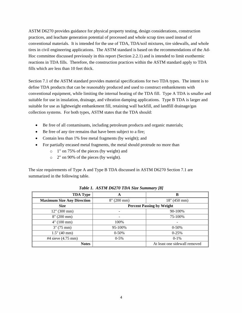
ASTM D6270 provides guidance for physical property testing, design considerations, construction practices, and leachate generation potential of processed and whole scrap tires used instead of conventional materials. It is intended for the use of TDA, TDA/soil mixtures, tire sidewalls, and whole tires in civil engineering applications. The ASTM standard is based on the recommendations of the Ad-Hoc committee discussed previously in this report (Section 2.2.1) and is intended to limit exothermic reactions in TDA fills. Therefore, the construction practices within the ASTM standard apply to TDA fills which are less than 10 feet thick. Section 7.1 of the ASTM standard provides material specifications for two TDA types. The intent is to define TDA products that can be reasonably produced and used to construct embankments with conventional equipment, while limiting the internal heating of the TDA fill. Type A TDA is smaller and suitable for use in insulation, drainage, and vibration damping applications. Type B TDA is larger and suitable for use as lightweight embankment fill, retaining wall backfill, and landfill drainage/gas collection systems. For both types, ASTM states that the TDA should:
• Be free of all contaminants, including petroleum products and organic materials; • Be free of any tire remains that have been subject to a fire; • Contain less than 1% free metal fragments (by weight); and • For partially encased metal fragments, the metal should protrude no more than
o 1" on 75% of the pieces (by weight) and o 2" on 90% of the pieces (by weight).
The size requirements of Type A and Type B TDA discussed in ASTM D6270 Section 7.1 are summarized in the following table.
Table 1. ASTM D6270 TDA Size Summary [8] TDA Type A B
Maximum Size Any Direction 8" (200 mm) 18" (450 mm) Size Percent Passing by Weight
12" (300 mm) - 90-100% 8" (200 mm) - 75-100% 4" (100 mm) 100% - 3" (75 mm) 95-100% 0-50%
1.5" (40 mm) 0-50% 0-25% #4 sieve (4.75 mm) 0-5% 0-1%
Notes At least one sidewall removed
5
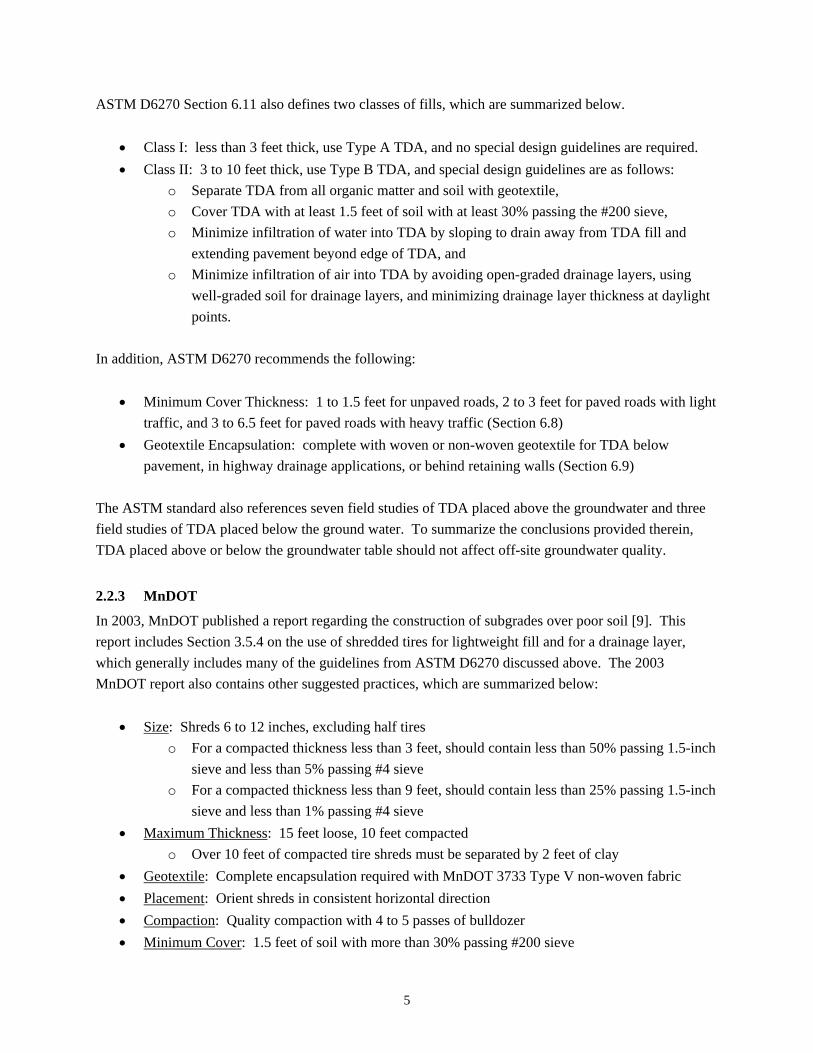
ASTM D6270 Section 6.11 also defines two classes of fills, which are summarized below.
• Class I: less than 3 feet thick, use Type A TDA, and no special design guidelines are required. • Class II: 3 to 10 feet thick, use Type B TDA, and special design guidelines are as follows:
o Separate TDA from all organic matter and soil with geotextile, o Cover TDA with at least 1.5 feet of soil with at least 30% passing the #200 sieve, o Minimize infiltration of water into TDA by sloping to drain away from TDA fill and
extending pavement beyond edge of TDA, and o Minimize infiltration of air into TDA by avoiding open-graded drainage layers, using
well-graded soil for drainage layers, and minimizing drainage layer thickness at daylight points.
In addition, ASTM D6270 recommends the following:
• Minimum Cover Thickness: 1 to 1.5 feet for unpaved roads, 2 to 3 feet for paved roads with light traffic, and 3 to 6.5 feet for paved roads with heavy traffic (Section 6.8)
• Geotextile Encapsulation: complete with woven or non-woven geotextile for TDA below pavement, in highway drainage applications, or behind retaining walls (Section 6.9)
The ASTM standard also references seven field studies of TDA placed above the groundwater and three field studies of TDA placed below the ground water. To summarize the conclusions provided therein, TDA placed above or below the groundwater table should not affect off-site groundwater quality.
2.2.3 MnDOT
In 2003, MnDOT published a report regarding the construction of subgrades over poor soil [9]. This report includes Section 3.5.4 on the use of shredded tires for lightweight fill and for a drainage layer, which generally includes many of the guidelines from ASTM D6270 discussed above. The 2003 MnDOT report also contains other suggested practices, which are summarized below:
• Size: Shreds 6 to 12 inches, excluding half tires o For a compacted thickness less than 3 feet, should contain less than 50% passing 1.5-inch
sieve and less than 5% passing #4 sieve o For a compacted thickness less than 9 feet, should contain less than 25% passing 1.5-inch
sieve and less than 1% passing #4 sieve • Maximum Thickness: 15 feet loose, 10 feet compacted
o Over 10 feet of compacted tire shreds must be separated by 2 feet of clay • Geotextile: Complete encapsulation required with MnDOT 3733 Type V non-woven fabric • Placement: Orient shreds in consistent horizontal direction • Compaction: Quality compaction with 4 to 5 passes of bulldozer • Minimum Cover: 1.5 feet of soil with more than 30% passing #200 sieve
6
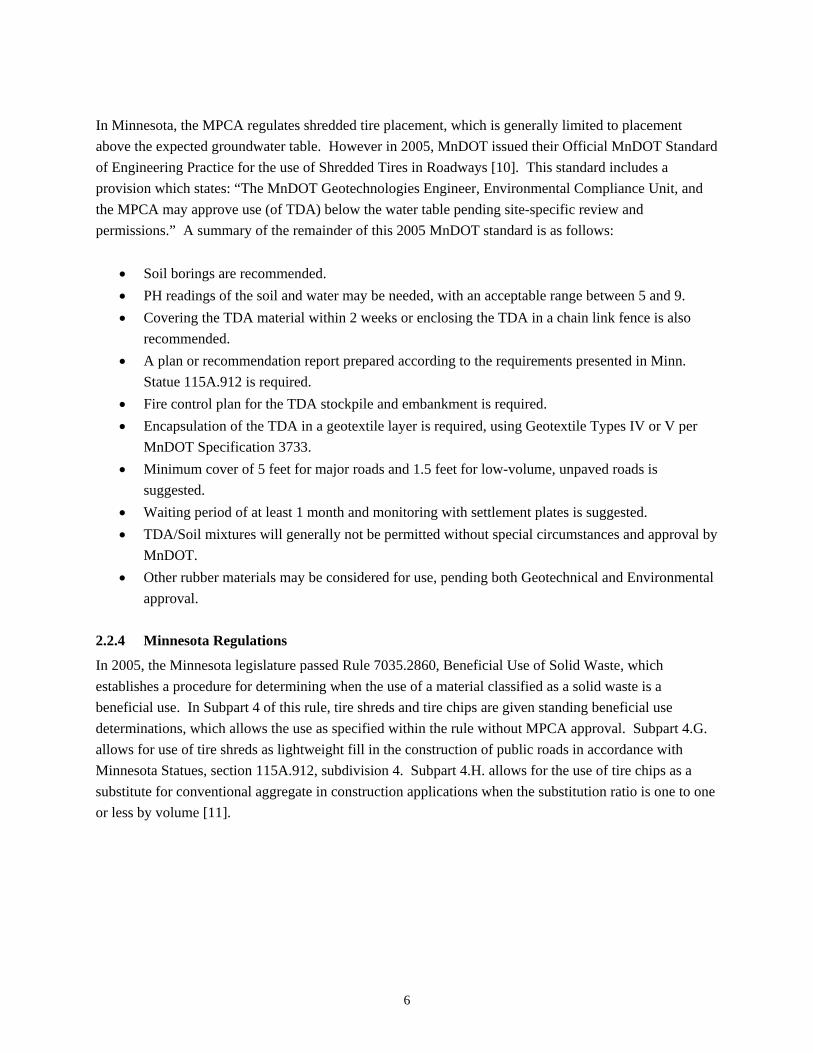
In Minnesota, the MPCA regulates shredded tire placement, which is generally limited to placement above the expected groundwater table. However in 2005, MnDOT issued their Official MnDOT Standard of Engineering Practice for the use of Shredded Tires in Roadways [10]. This standard includes a provision which states: “The MnDOT Geotechnologies Engineer, Environmental Compliance Unit, and the MPCA may approve use (of TDA) below the water table pending site-specific review and permissions.” A summary of the remainder of this 2005 MnDOT standard is as follows:
• Soil borings are recommended. • PH readings of the soil and water may be needed, with an acceptable range between 5 and 9. • Covering the TDA material within 2 weeks or enclosing the TDA in a chain link fence is also
recommended. • A plan or recommendation report prepared according to the requirements presented in Minn.
Statue 115A.912 is required. • Fire control plan for the TDA stockpile and embankment is required. • Encapsulation of the TDA in a geotextile layer is required, using Geotextile Types IV or V per
MnDOT Specification 3733. • Minimum cover of 5 feet for major roads and 1.5 feet for low-volume, unpaved roads is
suggested. • Waiting period of at least 1 month and monitoring with settlement plates is suggested. • TDA/Soil mixtures will generally not be permitted without special circumstances and approval by
MnDOT. • Other rubber materials may be considered for use, pending both Geotechnical and Environmental
approval.
2.2.4 Minnesota Regulations
In 2005, the Minnesota legislature passed Rule 7035.2860, Beneficial Use of Solid Waste, which establishes a procedure for determining when the use of a material classified as a solid waste is a beneficial use. In Subpart 4 of this rule, tire shreds and tire chips are given standing beneficial use determinations, which allows the use as specified within the rule without MPCA approval. Subpart 4.G. allows for use of tire shreds as lightweight fill in the construction of public roads in accordance with Minnesota Statues, section 115A.912, subdivision 4. Subpart 4.H. allows for the use of tire chips as a substitute for conventional aggregate in construction applications when the substitution ratio is one to one or less by volume [11].
7
CHAPTER 3: HIGHWAY APPLICATIONS
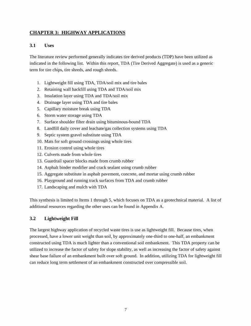
3.1 Uses The literature review performed generally indicates tire derived products (TDP) have been utilized as indicated in the following list. Within this report, TDA (Tire Derived Aggregate) is used as a generic term for tire chips, tire shreds, and rough shreds.
1. Lightweight fill using TDA, TDA/soil mix and tire bales 2. Retaining wall backfill using TDA and TDA/soil mix 3. Insulation layer using TDA and TDA/soil mix 4. Drainage layer using TDA and tire bales 5. Capillary moisture break using TDA 6. Storm water storage using TDA 7. Surface shoulder filter drain using bituminous-bound TDA 8. Landfill daily cover and leachate/gas collection systems using TDA 9. Septic system gravel substitute using TDA 10. Mats for soft ground crossings using whole tires 11. Erosion control using whole tires 12. Culverts made from whole tires 13. Guardrail spacer blocks made from crumb rubber 14. Asphalt binder modifier and crack sealant using crumb rubber 15. Aggregate substitute in asphalt pavement, concrete, and mortar using crumb rubber 16. Playground and running track surfaces from TDA and crumb rubber 17. Landscaping and mulch with TDA
This synthesis is limited to Items 1 through 5, which focuses on TDA as a geotechnical material. A list of additional resources regarding the other uses can be found in Appendix A.
3.2 Lightweight Fill The largest highway application of recycled waste tires is use as lightweight fill. Because tires, when processed, have a lower unit weight than soil, by approximately one-third to one-half, an embankment constructed using TDA is much lighter than a conventional soil embankment. This TDA property can be utilized to increase the factor of safety for slope stability, as well as increasing the factor of safety against shear base failure of an embankment built over soft ground. In addition, utilizing TDA for lightweight fill can reduce long term settlement of an embankment constructed over compressible soil.

8
3.3 Retaining Wall Backfill The use of TDA as retaining wall backfill is a newer application that has been studied more in the last decade. The lighter weight of TDA reduces the lateral load on retaining walls and bridge abutments, allowing for a more economical wall design by utilizing a thinner wall with less reinforcing. Often the retaining wall backfill applications include a TDA/sand mixture. Some full scale testing has been performed [12], and pull-out testing has been performed for TDA/sand mixtures with metal straps, ribbed metal strips, and geogrids [13]. In addition, a few full scale construction projects utilizing this approach have been published [14, 15]. 3.4 Insulation layer Because TDA has a lower thermal conductivity than soil, about 7 to 8 times lower [16], it can be used to reduce subgrade frost heave by decreasing the depth of frost penetration. Potential problems with this application include differential icing and reduced subgrade strength, both of which occur if TDA is placed too near the final surface. Larger TDA generally has a lower insulating value due to the larger amount of void space [16]. The insulating value of TDA tends to decrease with increasing density [16]. The effectiveness of insulating properties of TDA decreases as the thickness of the overlying soil cover increases [17]. Published research and test sections utilizing this application exist [17, 18]; however, there seems to be a lack of published full scale construction projects utilizing this approach. 3.5 Drainage Layer The high permeability or large hydraulic conductivity of TDA, similar to that of gravel, makes it a good material for drainage applications [19]. However, the hydraulic conductivity of TDA decreases when the material is compressed [3]. TDA, in the form of large shreds or tire bales, has been widely used in landfill drainage, leachate, and gas collection applications in the United States and Europe [18, 20, 21]. In a highway application in Maine, iron eating bacteria has created aesthetic issues with the effluent emanating from a TDA ditch drain [22, 23]. 3.6 Capillary Moisture Break As soils freeze from the top, water is drawn upwards through the pore spaces within the soil toward the freezing front. Silty soils are most susceptible because of the capillary pore space size. This capillary rise of pore water toward the freezing front leads to the formation of ice lenses, which expand in volume, exert enormous pressures within the soil, and result in frost heave of the subgrade. In addition, ice lens formation and frost heave tends to be variable, following the path of least resistance within the soil.
In the spring when the subgrade thaws from the top down, the ice lenses melt, convert to water, reduce in volume, and then become trapped above the still frozen subgrade below. This process, referred to as thaw
9
weakening, results in a wet, weak upper subgrade that becomes subject to rutting from traffic loads and leads to distress of the surfacing above. A capillary barrier or moisture break is a material with a pore size large enough such that pore water cannot rise up in the soil toward the freezing front. Typically such materials are free draining and therefore contain negligible moisture. Providing a capillary moisture break for a roadway reduces ice lens formation and subsequently frost heaving and thaw weakening. Due to its large pore space, TDA seems a good candidate for use as a capillary moisture break. The results of three test sections constructed in Georgia, Vermont indicate an 8 to 9-inch thick layer of TDA can cut off capillary rise of subsurface water and provide drainage of the overlying gravel for better roadway performance during the spring thaw [24].

10
CHAPTER 4: TEST SECTIONS AND PROJECTS The following sections summarize some of the test sections and case histories described in the literature we reviewed. 4.1 Colorado A 5-foot thick test embankment, including three distinct sections, was constructed with TDA at the Front Range Tire Recycle, Inc. facility in Sedalia, Colorado [25]. The first section included two 6-inch thick layers of pure TDA covered by 2-foot thick layers of soil. The second section included a 10% TDA/soil mixture (by weight) with 1-foot of soil cover. The third section consisted of pure soil as a control section. The TDA ranged from 2 to 6 inches in length and was about 1-inch wide. The soil used was classified as silty sand (SM) per the Unified Soil Classification System (USCS). No geotextile was used to separate the TDA or TDA/soil mixture from the pure soil. The material was compacted with four passes of a 6.7-ton sheepsfoot roller. Settlement was monitored for over 2 years, during which the access road was subject to an average of 20 trucks per day. For the TDA layered and TDA/soil mix sections, settlement rates during the first 120 days were about 2 times and 1.6 times that of the control section, , respectively, which was 0.015 inches per day. Beyond 120 days, the settlement rates for both TDA sections and the control decreased substantially. The TDA layered section and TDA/soil mix section settled 4.25 and 4.75 inches over the monitoring period, respectively, compared to the control section at 2.6 inches. Both TDA sections exhibited the formation of small sinkholes, presumably due to the lack of geotextile encapsulation. This study indicated a TDA/soil mixture of 30% by weight was difficult to achieve in the field. 4.2 Iowa A prototype drain was constructed using rough shreds, 4 to 8 inches in width and 8 to 16 inches in length, in order to investigate a replacement for conventional field draintile, drainage pipes, and gravel [26]. Laboratory compression tests indicated up to 50% strain under a load of about 600 psf for this large shred material. The prototype field drain was 65 feet long, 4.5 feet wide, and ranged from 5 to 6.5 feet thick. No geotextile fabric was used and soil cover above the trench ranged from about 3.5 to 4 feet thick. Settlement plates indicated the large shreds compressed 10 inches, corresponding to about 13% to 17% of the tire shred thickness. Two flow tests (see source 26 for details) were conducted 8 months apart in order to test the ability of the field drain to transmit large volumes of water and to determine its long term effectiveness. The field hydraulic conductivity was measured to be 10 cm/sec, which was comparable to but slightly higher than the constant head hydraulic conductivity test results of 1.5 to 7 cm/sec found in the laboratory.
11
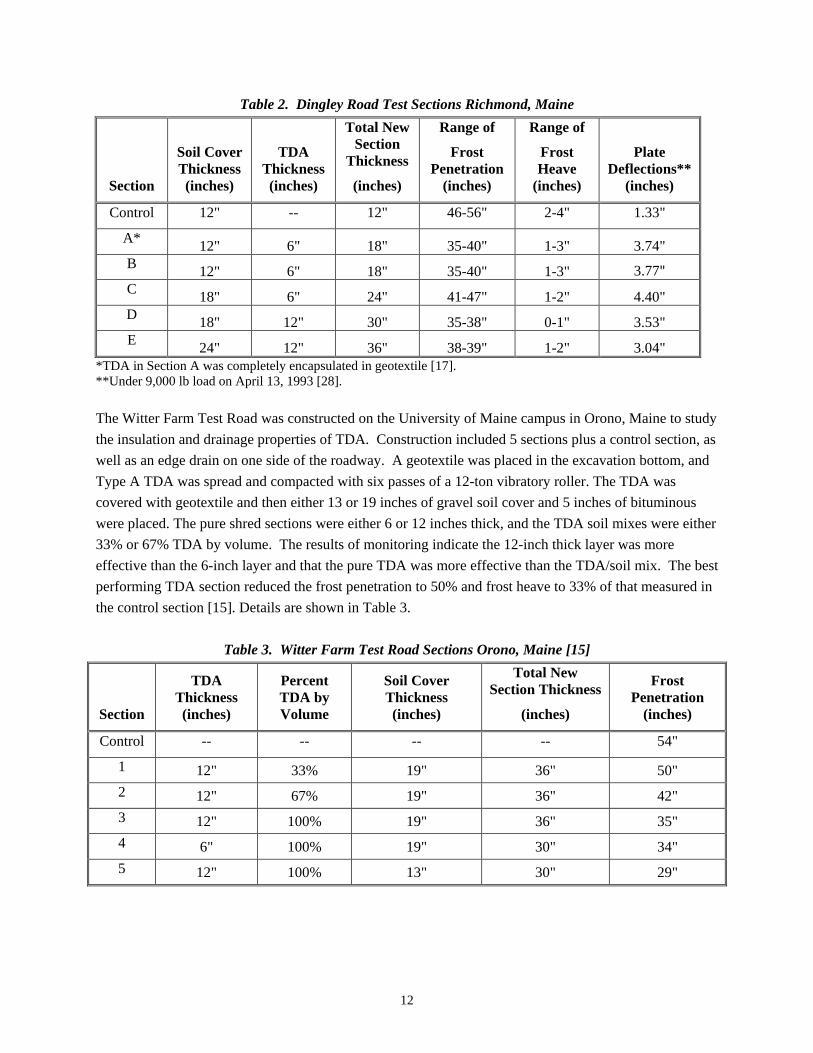
4.3 Indiana In 2008, two road widening projects in Indiana, SR-110 in Marshall County and SR-19 in Elkhart County, required grade raises over peat. For these projects, TDA/sand mixes (35% TDA by weight) were selected as lightweight fill to minimize settlement [14]. The TDA/soil mix was underlain by a geogrid over a geotextile fabric. The TDA/sand mix was spread with a dozer and compacted in 12-inch lifts with a smooth-drum 5-ton roller. A geotextile was then used above the TDA/sand mix in side slope areas, where the fabric was covered with 6 to 12-inches of topsoil. In pavement areas, geogrid alone was used above the TDA/sand mix, below 9 inches of aggregate base and an unknown thickness of bituminous pavement. Settlement monitoring indicated about 0.6 to 1-inch of settlement at SR-110 and about 0.1 to 1-inch of settlement of SR-19, during the first approximately 100 days the roadways were open to traffic. A TDA/sand mixture was utilized as lightweight backfill behind a 10-foot tall MSE wall constructed for widening of I-80 over 40 feet of poor riverbed soils in northwest Indiana [27]. The TDA/sand mix on this project was 25% TDA by weight and reinforcement consisted of metal straps [13]. A bottom aggregate layer, wall leveling pad, and the first course wall panels were installed. Then the TDA/sand mix was spread with a dozer, compacted in 12-inch lifts with a smooth-drum 10-ton roller, and covered with EPS blocks. Finally an aggregate base layer was spread and concrete pavement was constructed. Settlement monitoring, inclinometers, survey points, and crack gauges were used to monitor the wall, which moved vertically 0.12 inches and horizontally less than 0.05 inches. 4.4 Maine In 1992, test sections were constructed along Dingley Road in Richmond, Maine to investigate tire chips as an insulating layer to limit frost penetration [17]. The road was gravel surfaced and experienced severe rutting during the spring season. The underlying soils consisted of silty clay and silty gravelly sand over glacial till or bedrock. Normally, the ground water was 3 to 10 feet below the surface; however, during the spring thaw standing water was often observed at the surface. The existing 6 to 18 inches of existing road surface was excavated and the bottom of the excavation was sloped 4% to the ditch. Type A TDA was spread in maximum 12-inch lifts with a small bulldozer and compacted with six passes of a 9-ton, smooth-drum, vibratory roller. The gravel cover material was smaller than 6 inches and had 7% or less passing the #200 sieve. The 4-inch thick surface course was maximum 1-inch in size, contained up to 13% passing the #200 sieve, and was treated with flake calcium chloride [28].
Monitoring included thermal behavior, frost heave measurements, and groundwater quality over two winter seasons. In general, the TDA test sections remained stable during the spring thaw, while the adjacent road sections experienced severe rutting [28, 29]. Sections A and B experienced some rutting the first month after construction. Details of the TDA sections investigated as well as results of the monitoring are summarized in Table 2.
12
Table 2. Dingley Road Test Sections Richmond, Maine
Section
Soil Cover Thickness (inches)
TDA Thickness (inches)
Total New Section
Thickness
(inches)
Range of
Frost Penetration
(inches)
Range of
Frost Heave
(inches)
Plate Deflections**
(inches)
Control 12" -- 12" 46-56" 2-4" 1.33"
A* 12" 6" 18" 35-40" 1-3" 3.74" B 12" 6" 18" 35-40" 1-3" 3.77" C 18" 6" 24" 41-47" 1-2" 4.40" D 18" 12" 30" 35-38" 0-1" 3.53" E 24" 12" 36" 38-39" 1-2" 3.04"
*TDA in Section A was completely encapsulated in geotextile [17]. **Under 9,000 lb load on April 13, 1993 [28]. The Witter Farm Test Road was constructed on the University of Maine campus in Orono, Maine to study the insulation and drainage properties of TDA. Construction included 5 sections plus a control section, as well as an edge drain on one side of the roadway. A geotextile was placed in the excavation bottom, and Type A TDA was spread and compacted with six passes of a 12-ton vibratory roller. The TDA was covered with geotextile and then either 13 or 19 inches of gravel soil cover and 5 inches of bituminous were placed. The pure shred sections were either 6 or 12 inches thick, and the TDA soil mixes were either 33% or 67% TDA by volume. The results of monitoring indicate the 12-inch thick layer was more effective than the 6-inch layer and that the pure TDA was more effective than the TDA/soil mix. The best performing TDA section reduced the frost penetration to 50% and frost heave to 33% of that measured in the control section [15]. Details are shown in Table 3.
Table 3. Witter Farm Test Road Sections Orono, Maine [15]
Section
TDA Thickness (inches)
Percent TDA by Volume
Soil Cover Thickness (inches)
Total New Section Thickness
(inches)
Frost Penetration
(inches)
Control -- -- -- -- 54"
1 12" 33% 19" 36" 50"
2 12" 67% 19" 36" 42"
3 12" 100% 19" 36" 35"
4 6" 100% 19" 30" 34"
5 12" 100% 13" 30" 29"
13
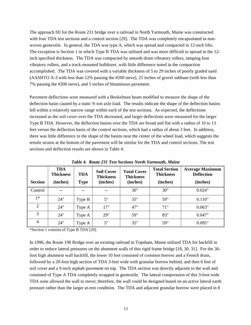
The approach fill for the Route 231 bridge over a railroad in North Yarmouth, Maine was constructed with four TDA test sections and a control section [29]. The TDA was completely encapsulated in non-woven geotextile. In general, the TDA was type A, which was spread and compacted in 12-inch lifts. The exception is Section 1 in which Type B TDA was utilized and was more difficult to spread in the 12-inch specified thickness. The TDA was compacted by smooth drum vibratory rollers, tamping foot vibratory rollers, and a track-mounted bulldozer, with little difference noted in the compaction accomplished. The TDA was covered with a variable thickness of 5 to 29 inches of poorly graded sand (AASHTO A-3 with less than 12% passing the #200 sieve), 25 inches of gravel subbase (with less than 7% passing the #200 sieve), and 5 inches of bituminous pavement. Pavement deflections were measured with a Benkelman beam modified to measure the shape of the deflection basin caused by a static 9–ton axle load. The results indicate the shape of the deflection basins fell within a relatively narrow range within each of the test sections. As expected, the deflections increased as the soil cover over the TDA decreased, and larger deflections were measured for the larger Type B TDA. However, the deflection basins over the TDA are broad and flat with a radius of 10 to 13 feet versus the deflection basin of the control sections, which had a radius of about 3 feet. In addition, there was little difference in the shape of the basins near the center of the wheel load, which suggests the tensile strains at the bottom of the pavement will be similar for the TDA and control sections. The test sections and deflection results are shown in Table 4.
Table 4. Route 231 Test Sections North Yarmouth, Maine
Section
TDA Thickness
(inches)
TDA
Type
Soil Cover Thickness (inches)
Total Cover Thickness (inches)
Total Section Thickness
(inches)
Average Maximum Deflection
(inches)
Control -- -- -- 30" 30" 0.024"
1* 24" Type B 5" 35" 59" 0.110"
2 24" Type A 17" 47" 71" 0.063"
3 24" Type A 29" 59" 83" 0.047"
4 24" Type A 5" 35" 59" 0.095"
*Section 1 consists of Type B TDA [29]. In 1996, the Route 196 Bridge over an existing railroad in Topsham, Maine utilized TDA for backfill in order to reduce lateral pressures on the abutment walls of this rigid frame bridge [18, 30, 31]. For the 36-foot high abutment wall backfill, the lower 10 feet consisted of common borrow and a French drain, followed by a 20-foot high section of TDA 3-feet wide with granular borrow behind, and then 6 feet of soil cover and a 9-inch asphalt pavement on top. The TDA section was directly adjacent to the wall and consisted of Type A TDA completely wrapped in geotextile. The lateral compression of this 3-foot wide TDA zone allowed the wall to move; therefore, the wall could be designed based on an active lateral earth pressure rather than the larger at-rest condition. The TDA and adjacent granular borrow were placed in 8
14
inch lifts and compacted with 4 passes of a 1.4-ton walk-behind roller. Pressure cells mounted on the concrete walls both below and within the TDA fill zone indicate the lateral pressure exerted on the wall in the TDA zone was half that of the pressure in the soil zone. In 1998, TDA was used as lightweight fill in both bridge approach embankments for the Portland Interchange project in Portland, Maine [15]. The 32-foot high approach fills for the new bridge would be too heavy if constructed with conventional soil, resulting in slope stability issues. Type B TDA per ASTM D6270 was placed in two layers, which were a maximum of 10 feet thick, were completely encapsulated by a geotextile fabric, and were separated by a 3-foot thick layer of soil with more then 30% passing the #200 sieve. The TDA was placed in 12 inch lifts with a D-4 dozer and compacted with six passes of a 10-ton vibratory roller. Side cover over the embankment consisted of 6 feet of soil with more then 30% passing the #200 sieve, and the top cover included 4 feet of granular subbase. A 4-foot thick surcharge was placed over the subbase material, in order to preload the underlying soft clays prior to paving. Prefabricated vertical drains had been installed within the underlying soft clays prior to TDA placement. Temperature monitoring of the TDA fills showed no evidence of self heating over the 10 month monitoring period. In 2000, shredded tires were used to construct a subgrade French drain in the ditch profile along the Route 27 reconstruction project near Rome, Maine [22, 23]. The project was used to investigate if the insulating value of the TDA would prevent ice build-up and subsequent clogging of the drain, which can be very problematic in the spring when run-off volumes peak. The 4400-foot long French drain was constructed with Type A TDA placed 4 feet wide and 3 feet deep [32]. The TDA was placed and compacted in 12-inch lifts and then completely encapsulated in a geotextile fabric with overlapped seams. Thermocouples were installed in several locations within the drain and two monitoring wells were installed to measure water levels within the drain. During the spring of 2001, the drain performed well and large amounts of water flowed from the system. However, that winter there was a large amount of snow, and temperatures never reached the freezing point within the drain [22]. In the spring of 2003, ice and snow were observed in the ditch long after other areas had melted. Despite the deep frost that year, the drain appeared to function well during the spring runoff. General observations included a crack that developed in the pavement surface adjacent to the drain and rust colored discharge water coming from the drain. 4.5 Minnesota In 2006 on the TH 212 design-build project (SP 1017-12) in Eden Prairie, Minnesota the Contractor built noise berm and roadway embankments with multiple layers of TDA for load reduction over a large diameter Metropolitan Council Environmental Services (MCES) sewer pipe [Gebhard]. In 2010 on the TH 610 design-build project (SP 2771-38) in Maple Grove, Braun Intertec designed a single layer of TDA for load reduction over a 54-inch MCES sanitary sewer interceptor pipe [Oman].

15
The TDA consisted of shreds 4 to 8 inches in length that were encapsulated in a MnDOT Spec. 3733 Class V geotextile with sewn seams. The TDA was placed and compacted with a bulldozer in maximum 2-foot lifts. In ditch areas, the cover consisted of 6 inches of topsoil over 18 inches of granular soil. In the Great River Energy tower access road area, the cover consisted of 12 inches of MnDOT Class 5 aggregate base over 12 inches of granular material. In 2010 near Mankato, TDA was used as lightweight fill to partially reconstruct a 30-foot tall bridge approach embankment, which developed longitudinal cracks shortly after construction. The approach embankment was for a new Blue Earth County Road 12 bridge over a rail line [33]. The approach embankment area was underlain by a previously undiscovered layer of peat up to 20 feet thick. The project included one layer of TDA similar to Type B which was up to 15 feet thick. The TDA was placed and compacted in 3-foot thick lifts with a tracked vehicle, wrapped with a geotextile fabric, and covered with at least 2 feet of soil. Settlement plates indicated about 2 feet of settlement (30% of the TDA thickness) occurred during a six month construction delay prior to paving and about 0.7 inches of post construction settlement occurred after paving. Inclinometers were installed prior to removal of the original embankment fill. They indicated about 0.5 to 3 inches of downslope movement during fill placement; however, negligible movement was measured after fill placement was compete. A shrinkage factor of 35% was calculated for the TDA used on this project.
4.6 New York In 1997, the New York State Department of Transportation (NYSDOT) established a pilot project in order to develop design, specification, and construction methods for the use of TDA in engineering applications [34]. The appropriate site was selected and in 1999, TDA was used as lightweight fill below a widened area of Route 17 near Binghamton, New York. The design and construction was based on the prior experiences of the Maine DOT. The Type B TDA fill was less than 10 feet thick, and a layer of geotextile was used below the TDA. Cover above the TDA was 3 to 5 feet of soil plus a 4 to 8-foot thick surcharge. The issues encountered during construction include an incomplete and non-continuous supply of TDA and difficulty with compaction of the unconfined side slopes of the TDA embankment. The monitoring reported settlement of about 10 to 13% of the TDA thickness during fill placement, with an additional 0.5 inches to 1-inch of settlement during the two months after fill placement was complete. Temperature readings indicated little to no self-heating of the TDA fill. 4.7 Texas
Between 1998 and 2000, three embankment fills for Woodrow Bean-Trans Mountain Road (Loop 375) in El Paso, Texas were constructed using sandy lean clay (CL), 50% volume mix of Type A TDA and CL,
16
and pure Type A TDA [35]. The TDA embankments were generally constructed per ASTM D6270 guidelines to reduce internal heating. Instrumentation included horizontal inclinometers, thermocouples, air sampling ducts, moisture detection units, and lysimeters. The conventional clay fill embankment was 12.6 feet thick, and it was placed and compacted in 12 inch lifts. The TDA/soil mix section consisted of a 6.6 foot thick fill constructed by placing 12 inches of soil over 12 inches of TDA, which were then uniformly mixed with a bulldozer, compacted in 24-inch thick layers with a non-vibratory Traxter, and ultimately covered with 13 feet of soil. The 5.4-foot thick pure TDA section was entirely encapsulated in geotextile, spread in 12-inch lifts with a bulldozer, compacted with a sheep’s foot roller, and covered with 20 feet of soil. About 0.3 inches of heave was measured for the conventional fill embankment, while maximum settlements of 0.8 and 5.5 inches were measured for the TDA/soil mix and pure TDA respectively. About 85% of the settlement of the pure TDA layer occurred prior to placement of the soil cover, under the movement of heavy construction traffic. Temperatures within the TDA fill embankments were higher than ambient temperatures; the temperatures were higher in the pure TDA versus the TDA/soil mix; and the maximum temperature recorded was 88°F. The moisture detection units indicated no water percolated down to the sumps for the lysimeters, so no leachate was tested. The air quality samples were collected to identify concentrations of any flammable compounds, and the non-detect or low levels measured indicated that no reactions were taking place in the TDA fills. A slope failure along I-30 east of Fort Worth, Texas was repaired in 2002 (Phase One) using three layers of tire bales separated by 6 to 8-inch thick layers of soil [36]. No monitoring was performed for Phase One of this project, and other than issues with obtaining a large enough supply of tire bales, construction of the project was generally considered a success. This project prompted further research regarding the engineering properties of tire bales [37]. This reference provides an updated TxDOT Draft Specification based on that research. However, in the spring of 2005, the slope adjacent to the repaired slope failed [38]. The second slope failure is attributed to water from the original tire bales, which did not include a drainage layer, draining downhill into the adjacent slope. Repairs of the second slope failure (Phase Two) included a gravel drainage layer over a geotextile fabric located at the bottom of the tire bales. In this phase, the four layers of bales were stacked directly on top of one another and covered with geotextile. In addition, a drain outlet was installed between the two slope sections. Phase Two also include inclinometers and surveying points on the slope face. Two years of inclinometer readings, survey shots, and outlet drain flow monitoring were performed; however, initial inclinometer readings weren’t taken until three months after construction was complete.
17
4.8 Vermont Beginning in 1990, tire chips were used for a capillary break and drainage layer below a 330-foot section of Town Highway 4 (TH 4) in Georgia, Vermont [24]. The existing roadway consisted of a gravel surface elevated about 2 feet above the native soils, which generally consisted of 4 feet of silty sand (AASHTO A-2-4 with 24% to 43% passing the #200 sieve) over silty clay and clay. In summer, the ground water level was measured at the top of the silty clay. During the spring “mud season”, the road was often impassable by two-wheel drive vehicles, so the original 24-inch gravel surface and 6 inches of native subgrade were removed. A 6 to 9-inch loose thickness layer of Type A TDA was placed and covered with 21 to 24 inches of gravel, which contained between 8 and 15% passing the #200 sieve. Monitoring for the project included visual observations of the surface performance over time and installation of piezometers. Some fine longitudinal and transverse cracks were noted after construction but did not worsen over the fall season. At that time, average water levels were measured about 1-foot below the bottom of the TDA. During the following spring, visual observations indicated the surface of the TDA section was dry and free of rutting, while the adjacent portions of the roadway without TDA were visibly wet and soft to walk on; contained numerous ruts, cracks, and boils; and allowed water to be drawn up to the surface with tamping action. At this time, water levels were measured about 6 inches below the bottom of the TDA. In 1991, another segment of TH 4 was reconstructed using TDA, more piezometers were installed, and a test pit was excavated in the original 1990 test section. In this test pit, the top of the TDA indicated a trace of moisture, the bottom of the TDA layer was dry, and the underlying silty sand subgrade was near its optimum moisture content. The two TDA sections were chip-sealed in the fall of 1992; subsequent inspection in the fall of 1993, indicated fine transverse and longitudinal cracks and minimal stone loss. In the fall of 1994, another test section was constructed and FWD testing was performed on the two previously chip-sealed TDA sections as well as two adjacent bituminous paved sections without TDA. The measured deflections averaged 0.116 and 0.032 inches for the TDA and control sections, respectively, while the AASHTO structural numbers back calculated from the FWD data averaged 1.55 and 2.66 for the TDA and control sections, respectively. 4.9 Virginia In 1993, TDA soil mixes were used in the construction of the bridge approach embankments for the Route 646 Connector located north of Williamsburg in York County, Virginia [39]. The mixes included TDA up to 10 inches in length that were mixed with either silty sand or clayey silt in an approximate 50% volumetric ratio. The TDA embankment heights varied but were less than 20 feet, and side cover of at least 4 feet was provided over the TDA/soil mixture. The TDA was spread with a D-8 bulldozer and mixed with soil using a motor grader with scarifying teeth. The mix was compacted in maximum 1-foot lifts with at least three passes of a 26-ton steel wheel roller. A 5-foot thick compacted soil cap was placed over the TDA/soil mix, followed by a 5-foot thick un-compacted surcharge. Other than achieving a
18
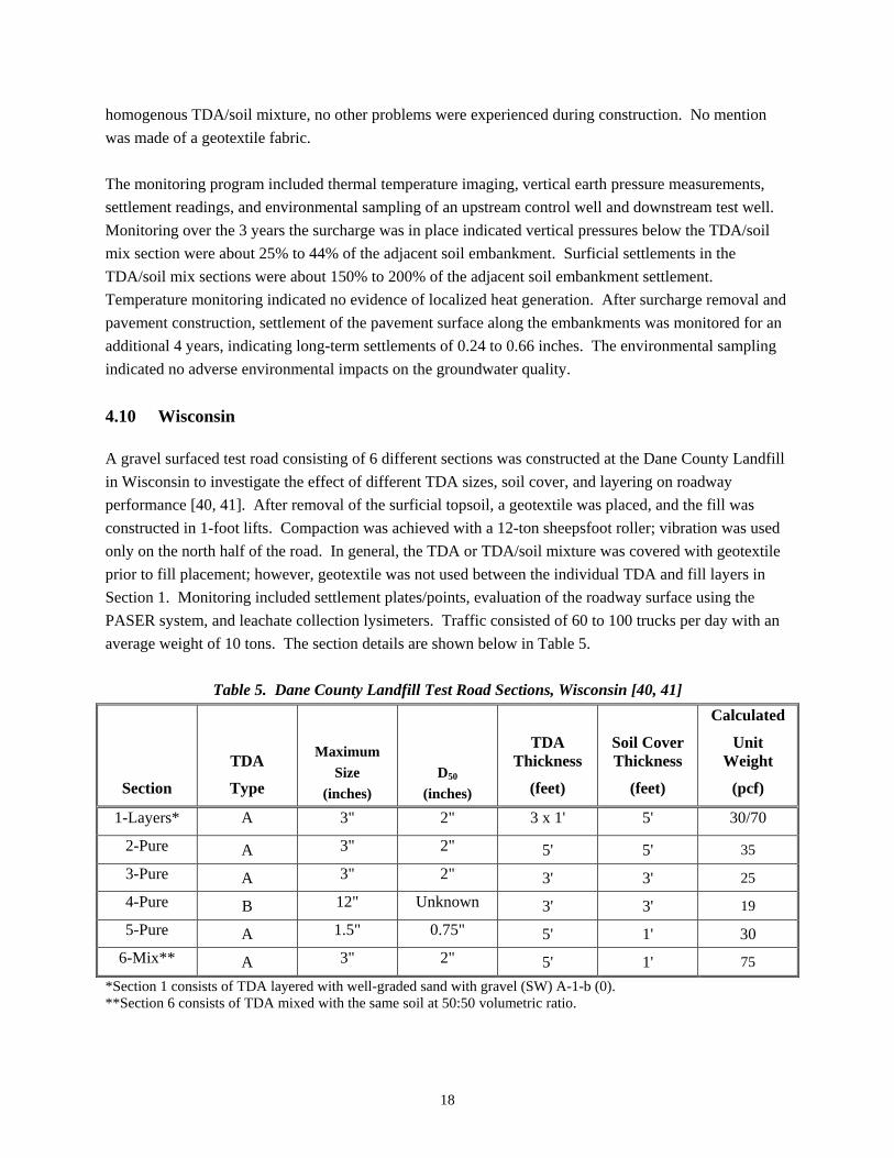
homogenous TDA/soil mixture, no other problems were experienced during construction. No mention was made of a geotextile fabric. The monitoring program included thermal temperature imaging, vertical earth pressure measurements, settlement readings, and environmental sampling of an upstream control well and downstream test well. Monitoring over the 3 years the surcharge was in place indicated vertical pressures below the TDA/soil mix section were about 25% to 44% of the adjacent soil embankment. Surficial settlements in the TDA/soil mix sections were about 150% to 200% of the adjacent soil embankment settlement. Temperature monitoring indicated no evidence of localized heat generation. After surcharge removal and pavement construction, settlement of the pavement surface along the embankments was monitored for an additional 4 years, indicating long-term settlements of 0.24 to 0.66 inches. The environmental sampling indicated no adverse environmental impacts on the groundwater quality. 4.10 Wisconsin A gravel surfaced test road consisting of 6 different sections was constructed at the Dane County Landfill in Wisconsin to investigate the effect of different TDA sizes, soil cover, and layering on roadway performance [40, 41]. After removal of the surficial topsoil, a geotextile was placed, and the fill was constructed in 1-foot lifts. Compaction was achieved with a 12-ton sheepsfoot roller; vibration was used only on the north half of the road. In general, the TDA or TDA/soil mixture was covered with geotextile prior to fill placement; however, geotextile was not used between the individual TDA and fill layers in Section 1. Monitoring included settlement plates/points, evaluation of the roadway surface using the PASER system, and leachate collection lysimeters. Traffic consisted of 60 to 100 trucks per day with an average weight of 10 tons. The section details are shown below in Table 5.
Table 5. Dane County Landfill Test Road Sections, Wisconsin [40, 41]
Section
TDA
Type
Maximum Size
(inches) D50
(inches)
TDA Thickness
(feet)
Soil Cover Thickness
(feet)
Calculated
Unit Weight
(pcf)
1-Layers* A 3" 2" 3 x 1' 5' 30/70
2-Pure A 3" 2" 5' 5' 35
3-Pure A 3" 2" 3' 3' 25
4-Pure B 12" Unknown 3' 3' 19
5-Pure A 1.5" 0.75" 5' 1' 30 6-Mix** A 3" 2" 5' 1' 75
*Section 1 consists of TDA layered with well-graded sand with gravel (SW) A-1-b (0). **Section 6 consists of TDA mixed with the same soil at 50:50 volumetric ratio.

19
Rutting was noted almost immediately after opening the road to traffic, and the road was repeatedly re-graded over the first year due to the formation of ruts and potholes. Sections 3, 4, and 6 settled about 3 to 3.5 inches and performed the best, indicating the sections with more soil cover performed better. In addition, Section 3 performed somewhat better than Section 4, indicating that for the same cover thickness, the smaller TDA size performed better. The layered Section 1 performed the worst and settled almost 6 inches. The settlement rate of the TDA fills was much faster in the first 60 days of monitoring. The environmental testing indicated little likelihood of TDA having adverse effects on groundwater quality. 4.11 Canada In 2000, a combination of large shreds and tire sidewalls were used to construct a 1000-foot long embankment over soft ground northeast of Winnipeg, Manitoba, Canada [42]. The section consisted of five layers of tire sidewalls, a 5-foot shredded tire layer, and 18-inches of gravel cover. To investigate compressibility, settlement plates were installed and the surface was loaded statically with a 46,000 pound tandem axle. Surveyed deflections measured about 0.6 inches with a maximum of 1-inch. The load was removed and reloaded, which produced greater surface deflections. The instantaneous rebound after unloaded was about 0.4 inches and the increase in deflection was about 0.3 inches. The project also included instrumentation to monitor frost depths. However, it appears frost penetration and temperature controls were located in a snow covered swamp adjacent to the new gravel road. Therefore, due to plowing and little no snow cover on the road, the frost penetration was deeper in the TDA roadway section than the control section located in the snow covered swamp. In 2007, TDA was used as lightweight fill after an embankment failure occurred during construction of the Route 1 highway embankment near St. Stephen, New Brunswick [43]. The embankment was approximately 40 feet high when it failed, due to the underlying soft marine clay. The remediation design includes two-stage construction utilizing prefabricated vertical drains in the underlying clay. It also includes two layers of Type B TDA, each 10 feet thick and fully wrapped in a woven geotextile. The TDA was covered by at least 3 feet of low permeability soil, containing at least 30% passing the #200 sieve, and the final cover in pavement areas will be 7 feet. Due to underestimated quantities of TDA, only the first stage construction was completed in 2007. The TDA was placed in 16-inch lifts with a bulldozer and compacted with 6 passes of a smooth drum vibratory roller. When complete this project will utilize approximately 1.6 million tires, which is equivalent to two years of scrap tire generation in the province of New Brunswick. 4.12 Europe Near the city of Porvoo, Finland, a test road was constructed using TDA for lightweight fill [44]. The TDA thickness varied from 1 to 4.5 feet, and it was covered with about 4 feet of gravel subbase and about 23 inches of bituminous pavement. Environmental sampling was to take place for a period of about 10 years.
20
Tire bales were used as lightweight fill in a ramp for the high traffic volume Tampere Western Ring Road project in Tampere, Finland [45]. The tire bale section is about 425 feet in length, and the bales are about 2.5 by 4 by 5 feet in size. The underlying soil consists of weak clay extending down to about 33 feet. The bottom layer of the road embankment consists of one layer of tire bales surrounded by filter cloth and covered by a steel wire net. The road section includes 40 inches of crushed stone aggregate under the pavement. TDA was studied and utilized in 1994 in a bituminous bound shoulder surface drain in England [46]. The TDA ultimately used meets the Type A size requirements in ASTM D6270. The proportion of bituminous binder used is about 25%. The material was laid in a single 6-inch thick layer over an area about 5 feet wide at the outside shoulder of a bituminous multilane roadway. Field testing of the drainage capacity of the bituminous-bound TDA exceeded the values obtained in the laboratory, and the field capacity of the bituminous-bound TDA was effectively the same as laboratory measurements for clean stone drainage material. The overall assessment indicated the bituminous-bound surface drains were in good serviceable condition after a 12-month monitoring period.

21
CHAPTER 5: PROPERTIES A subtask for this project was to summarize properties of TDA materials for use in design. These properties include the following: unit weight, specific gravity, absorption, void ratio, compressibility, lateral earth pressures, shear strength, thermal conductivity, permeability, and various pavement design parameters. ASTM D6270 provides guidance on the adjustments necessary to typical laboratory testing equipment due to the larger size of TDA as compared to typical geomaterials.
5.1 Dry Density and Compaction The compacted dry density of TDA generally ranges from about 35 to 60 pounds per cubic foot (pcf), which is about one-third to one-half of a typical soil. The specific gravity of tire chips, with maximum sizes of 1.5 to 3 inches and D50 sizes of 0.8 to 1.5 inches, was measured to range from 1.13 to 1.36, depending on metal content [47]. In addition, the tire chips without metal were found to have a very narrow range of specific gravities at about 1.15 [47].
Table 6. General Properties
Maximum Size
(inches) D50
(inches)
Apparent Specific Gravity
Loose or Minimum
Unit Weight (pcf)
Compacted* or Maximum Unit
Weight (pcf)
Absorption (%) Source
1.5 0.8 1.14 30.9 38.6 3.8 [48] 1.8 1.0 1.24 30.1 40.1 2.0 [48] 2.0 0.875 1.18 25.6 35.3 9.5 [19] 2.0 1.2 1.23 25.5 39.0 4.3 [48] 2.5 2.0 1.19 27.3 31.4 2.8 [19] 3.0 2.0 1.27 21.3 38.7 2.0 [48]
*60% of the Standard Proctor Energy [48]. Compaction effort beyond a certain level, approximately 50% to 60% of the Standard Proctor energy, has little effect on compacted dry density of TDA [49]. Similarly, the water content has a negligible effect on compaction of TDA [48]. Vibration appears to have a negligible effect on compaction of pure TDA [47, 50], but it is useful for compaction of TDA/sand mixes [47, 51]. Compaction is typically accomplished in the field with tracked bulldozers, sheepsfoot rollers, or smooth drum rollers making 4 to 6 passes over each lift. Lift thicknesses have ranged from 6 inches to 3 feet. The dry density assumed in design should consider the compression of the TDA under its own weight as well as the weight of soil cover and/or surcharge placed above.
22
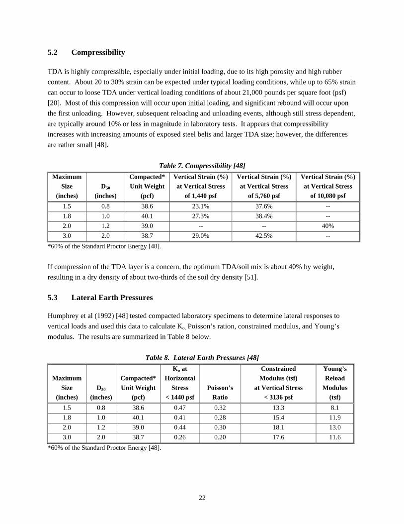
5.2 Compressibility TDA is highly compressible, especially under initial loading, due to its high porosity and high rubber content. About 20 to 30% strain can be expected under typical loading conditions, while up to 65% strain can occur to loose TDA under vertical loading conditions of about 21,000 pounds per square foot (psf) [20]. Most of this compression will occur upon initial loading, and significant rebound will occur upon the first unloading. However, subsequent reloading and unloading events, although still stress dependent, are typically around 10% or less in magnitude in laboratory tests. It appears that compressibility increases with increasing amounts of exposed steel belts and larger TDA size; however, the differences are rather small [48].
Table 7. Compressibility [48] Maximum
Size (inches)
D50 (inches)
Compacted* Unit Weight
(pcf)
Vertical Strain (%) at Vertical Stress
of 1,440 psf
Vertical Strain (%) at Vertical Stress
of 5,760 psf
Vertical Strain (%) at Vertical Stress
of 10,080 psf 1.5 0.8 38.6 23.1% 37.6% -- 1.8 1.0 40.1 27.3% 38.4% -- 2.0 1.2 39.0 -- -- 40% 3.0 2.0 38.7 29.0% 42.5% --
*60% of the Standard Proctor Energy [48]. If compression of the TDA layer is a concern, the optimum TDA/soil mix is about 40% by weight, resulting in a dry density of about two-thirds of the soil dry density [51]. 5.3 Lateral Earth Pressures Humphrey et al (1992) [48] tested compacted laboratory specimens to determine lateral responses to vertical loads and used this data to calculate Ko, Poisson’s ration, constrained modulus, and Young’s modulus. The results are summarized in Table 8 below.
Table 8. Lateral Earth Pressures [48]
Maximum Size
(inches) D50
(inches)
Compacted* Unit Weight
(pcf)
Ko at Horizontal
Stress < 1440 psf
Poisson’s Ratio
Constrained Modulus (tsf)
at Vertical Stress < 3136 psf
Young’s Reload
Modulus (tsf)
1.5 0.8 38.6 0.47 0.32 13.3 8.1 1.8 1.0 40.1 0.41 0.28 15.4 11.9 2.0 1.2 39.0 0.44 0.30 18.1 13.0 3.0 2.0 38.7 0.26 0.20 17.6 11.6
*60% of the Standard Proctor Energy [48].
23
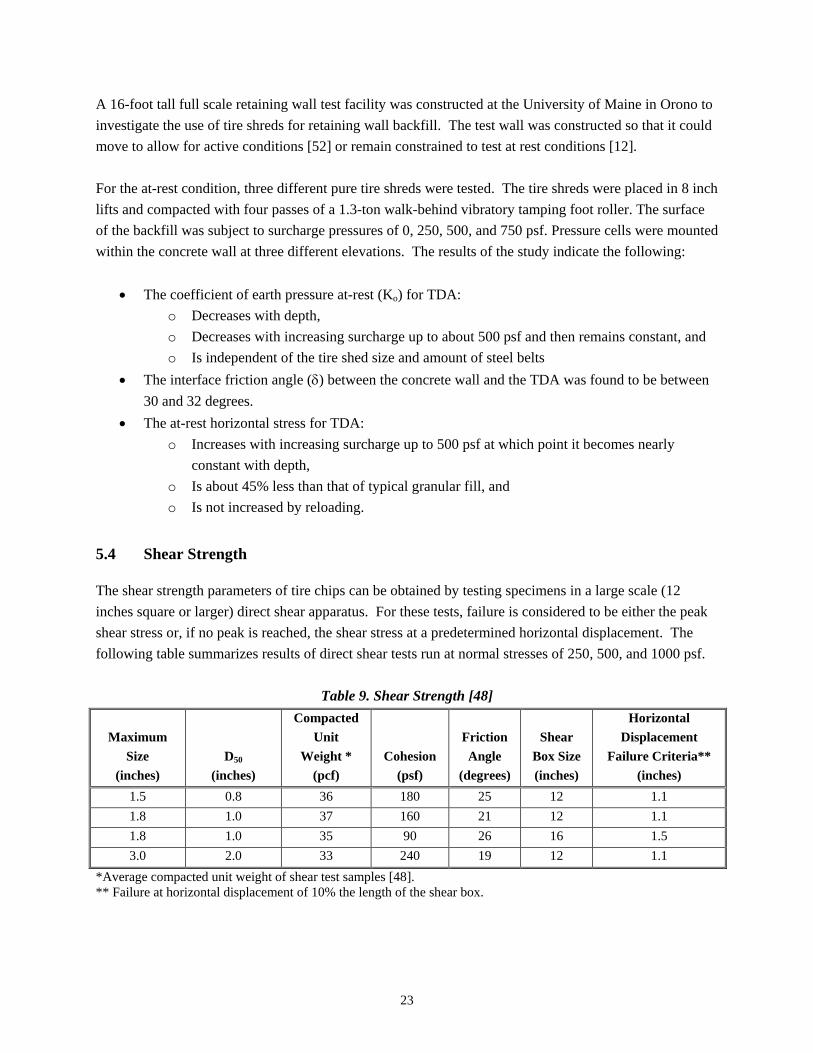
A 16-foot tall full scale retaining wall test facility was constructed at the University of Maine in Orono to investigate the use of tire shreds for retaining wall backfill. The test wall was constructed so that it could move to allow for active conditions [52] or remain constrained to test at rest conditions [12]. For the at-rest condition, three different pure tire shreds were tested. The tire shreds were placed in 8 inch lifts and compacted with four passes of a 1.3-ton walk-behind vibratory tamping foot roller. The surface of the backfill was subject to surcharge pressures of 0, 250, 500, and 750 psf. Pressure cells were mounted within the concrete wall at three different elevations. The results of the study indicate the following:
• The coefficient of earth pressure at-rest (Ko) for TDA: o Decreases with depth, o Decreases with increasing surcharge up to about 500 psf and then remains constant, and o Is independent of the tire shed size and amount of steel belts
• The interface friction angle (δ) between the concrete wall and the TDA was found to be between 30 and 32 degrees.
• The at-rest horizontal stress for TDA: o Increases with increasing surcharge up to 500 psf at which point it becomes nearly
constant with depth, o Is about 45% less than that of typical granular fill, and o Is not increased by reloading.
5.4 Shear Strength The shear strength parameters of tire chips can be obtained by testing specimens in a large scale (12 inches square or larger) direct shear apparatus. For these tests, failure is considered to be either the peak shear stress or, if no peak is reached, the shear stress at a predetermined horizontal displacement. The following table summarizes results of direct shear tests run at normal stresses of 250, 500, and 1000 psf.
Table 9. Shear Strength [48]
Maximum Size
(inches) D50
(inches)
Compacted Unit
Weight * (pcf)
Cohesion (psf)
Friction Angle
(degrees)
Shear Box Size (inches)
Horizontal Displacement
Failure Criteria** (inches)
1.5 0.8 36 180 25 12 1.1 1.8 1.0 37 160 21 12 1.1 1.8 1.0 35 90 26 16 1.5 3.0 2.0 33 240 19 12 1.1
*Average compacted unit weight of shear test samples [48]. ** Failure at horizontal displacement of 10% the length of the shear box.
24
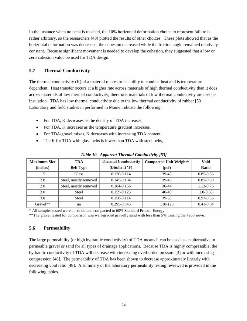
In the instance when no peak is reached, the 10% horizontal deformation choice to represent failure is rather arbitrary, so the researchers [48] plotted the results of other choices. These plots showed that as the horizontal deformation was decreased, the cohesion decreased while the friction angle remained relatively constant. Because significant movement is needed to develop the cohesion, they suggested that a low or zero cohesion value be used for TDA design. 5.7 Thermal Conductivity The thermal conductivity (K) of a material relates to its ability to conduct heat and is temperature dependent. Heat transfer occurs at a higher rate across materials of high thermal conductivity than it does across materials of low thermal conductivity; therefore, materials of low thermal conductivity are used as insulation. TDA has low thermal conductivity due to the low thermal conductivity of rubber [53]. Laboratory and field studies in performed in Maine indicate the following:
• For TDA, K decreases as the density of TDA increases, • For TDA, K increases as the temperature gradient increases, • For TDA/gravel mixes, K decreases with increasing TDA content, • The K for TDA with glass belts is lower than TDA with steel belts,
Table 10. Apparent Thermal Conductivity [53] Maximum Size
(inches) TDA
Belt Type Thermal Conductivity
(Btu/hr ft °F) Compacted Unit Weight*
(pcf) Void Ratio
1.5 Glass 0.120-0.114 39-45 0.85-0.56 2.0 Steel, mostly removed 0.145-0.134 39-45 0.85-0.60 2.0 Steel, mostly removed 0.184-0.156 36-44 1.13-0.76 3.0 Steel 0.159-0.125 40-49 1.0-0.63 3.0 Steel 0.158-0.114 39-50 0.97-0.56
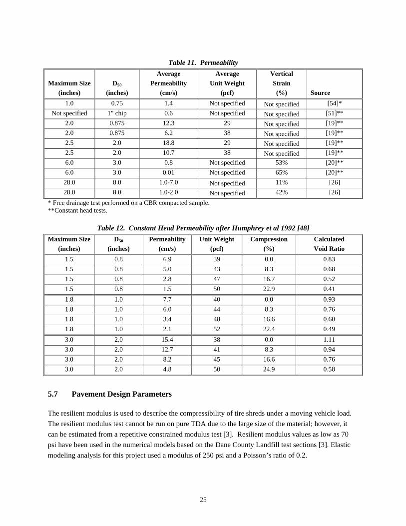
Gravel** na 0.295-0.345 118-123 0.41-0.34 * All samples tested were air-dried and compacted to 60% Standard Proctor Energy. **The gravel tested for comparison was well-graded gravelly sand with less than 5% passing the #200 sieve. 5.6 Permeability The large permeability (or high hydraulic conductivity) of TDA means it can be used as an alternative to permeable gravel or sand for all types of drainage applications. Because TDA is highly compressible, the hydraulic conductivity of TDA will decrease with increasing overburden pressure [3] or with increasing compression [48]. The permeability of TDA has been shown to decrease approximately linearly with decreasing void ratio [48]. A summary of the laboratory permeability testing reviewed is provided in the following tables.
25
Table 11. Permeability
Maximum Size (inches)
D50 (inches)
Average Permeability
(cm/s)
Average Unit Weight
(pcf)
Vertical Strain (%) Source
1.0 0.75 1.4 Not specified Not specified [54]* Not specified 1" chip 0.6 Not specified Not specified [51]**
2.0 0.875 12.3 29 Not specified [19]** 2.0 0.875 6.2 38 Not specified [19]** 2.5 2.0 18.8 29 Not specified [19]** 2.5 2.0 10.7 38 Not specified [19]** 6.0 3.0 0.8 Not specified 53% [20]** 6.0 3.0 0.01 Not specified 65% [20]**
28.0 8.0 1.0-7.0 Not specified 11% [26] 28.0 8.0 1.0-2.0 Not specified 42% [26]
* Free drainage test performed on a CBR compacted sample. **Constant head tests.
Table 12. Constant Head Permeability after Humphrey et al 1992 [48] Maximum Size
(inches) D50
(inches) Permeability
(cm/s) Unit Weight
(pcf) Compression
(%) Calculated Void Ratio
1.5 0.8 6.9 39 0.0 0.83 1.5 0.8 5.0 43 8.3 0.68 1.5 0.8 2.8 47 16.7 0.52 1.5 0.8 1.5 50 22.9 0.41 1.8 1.0 7.7 40 0.0 0.93 1.8 1.0 6.0 44 8.3 0.76 1.8 1.0 3.4 48 16.6 0.60 1.8 1.0 2.1 52 22.4 0.49 3.0 2.0 15.4 38 0.0 1.11 3.0 2.0 12.7 41 8.3 0.94 3.0 2.0 8.2 45 16.6 0.76 3.0 2.0 4.8 50 24.9 0.58
5.7 Pavement Design Parameters The resilient modulus is used to describe the compressibility of tire shreds under a moving vehicle load. The resilient modulus test cannot be run on pure TDA due to the large size of the material; however, it can be estimated from a repetitive constrained modulus test [3]. Resilient modulus values as low as 70 psi have been used in the numerical models based on the Dane County Landfill test sections [3]. Elastic modeling analysis for this project used a modulus of 250 psi and a Poisson’s ratio of 0.2.

26
Wisconsin has based their pavement design for TDA sections on 3 feet of soil cover over the TDA and a corresponding modulus of subgrade reaction of 60 pci [3]. Rahman reported a CBR value of 1.33% for TDA with a maximum size of 1 inch and a D50 of 0.75 inches [54].
27
CHAPTER 6: ENVIRONMENTAL STUDIES
A subtask for this project was to review environmental studies involving the use of tire chips both above and below the water table. 6.1 Background Information These studies generally fall into one of two categories: laboratory leaching tests or field studies. In the laboratory leaching studies, pieces of TDA are submerged in different solutions in order to determine what types of contaminants the TDA may produce under worst case conditions. In the laboratory, two protocols are typically used; these include Toxicity Characterization Leaching Procedure (TCLP) and Extraction Procedure Toxicity (EP or EP Tox). Toxicity refers to either the negative effects produced when an organism is exposed to a harmful material or the property of a substance that causes those negative effects [55]. The information from the laboratory leaching tests is used develop a comprehensive field study. In a field study, TDA is placed in the ground and then soil and water samples are collected over time to evaluate the effect of the TDA on the environment [56]. The Unites States Environmental Protection Agency (EPA) defines the following [57]:
• Primary Drinking Water Standards: legally enforceable standards that apply to public water systems, often referred to as regulatory allowable limits (RALs)
• Secondary Drinking Water Standards: non-enforceable guidelines regulating contaminants that may cause cosmetic effects (to skin or teeth) or aesthetic effects (such as taste, odor, or color) in drinking water.
• Preliminary Remediation Goals (PRG): risk-based concentrations for the human life-time.
6.2 1990 MPCA Study As discussed in Chapter 2, the original environmental study performed for the MPCA in 1990 indicated tires should only be used above the water table [5]. The intent of this study was to determine which compounds leach during extreme conditions by simulating some worst case scenarios [56]. It showed that highest levels of metals were leached in acidic conditions and that organics were leached in basic conditions. 6.3 1996 University of Wisconsin Madison Laboratory Investigation
This 1996 laboratory investigation at the University of Wisconsin in Madison was performed in order to study the leaching characteristics of TDA in various aquatic environments [58]. It included three batch tests of TDA placed in local groundwater, surface water from a wetland environment, and deionized water. The TDA samples were compared to control samples with the same aquatic environment but no TDA. The TDA particles used were 0.75 to 4 inches in length, and samples were collected over a 12-

28
month period. Initially, volatile organic compounds (VOCs) common to the tire manufacturing process and highway environment were found in all three TDA tanks, but after 7 months they reduced to insignificant levels. Iron, lead, and manganese leached from the TDA; however, these metals were found in levels below the Wisconsin State Groundwater Quality Standards. 6.4 1998 Chelsea Center Literature Review
This literature review [56] discusses five laboratory leaching studies: Illinois Department of Energy and Natural Resources 1990, MPCA 1990, Scrap Tire Management Council 1991,Wisconsin DOT 1992, and Virginia DOT 1992. All five studies showed that higher concentrations of metals occur under acidic conditions (low pH) and higher levels of organics occur under basic conditions (high pH). Metals and organics were well below the TCLP and EP standards, indicating TDA is not a hazardous waste. This review also discusses three field studies regarding the impact of TDA on soil, which include: MPCA 1990, Kent State University 1997, and Wageningen Agricultural (Dutch) University 1996. The review states these field tests were not as complete as the available laboratory studies; that the data collected to that date suggested few if any potential problems; and that continued evaluation was prudent. In addition, this review discusses six field studies regarding the impact of TDA on water, which include: Tire Pond in Connecticut 1987, MPCA 1990, Wisconsin DOT 1992, Chenette Engineering Vermont 1993, and Two Field Studies by University of Maine 1997. In almost all of these studies iron exceeded the RAL, and in some studies manganese exceeded the RAL; however, these metals have only secondary drinking water standards and do not pose severe environmental problems. For other metallic and organic compounds, the results vary and appear to depend on local subsurface and infiltration conditions. Finally, this review discusses three studies regarding the impact of TDA on local ecology. The MPCA 1990 study included two general vegetation field surveys that indicated no observable difference at either of the study areas as compared to the control areas. Two laboratory studies, Abernethy 1994 and Nelson 1994, showed elevated levels of zinc as the primary toxicant. The review concludes that it is reasonable to use TDA in civil engineering applications, but that it is important to recognize that the impact of TDA on the environment will vary with local soil and water conditions.
6.5 2006 EPA Literature Review
6.5.1 General
A literature review of the water quality effects of TDA and rubber modified asphalt pavement was performed in 2006 for the USEPA [59]. The ten studies sited in this literature review tested for a variety of parameters with differing detection levels. All of the projects included some metals and pH, while limited studies included total dissolved solids (TDS), total solids (TS), biological oxygen demand (BOD),
29
chemical oxygen demand (COD), organic compounds, and inorganic compounds. Only two included toxicity effects on aquatic life of fathead minnows (pimephales promelas) and a small crustacean (Ceriopdaphnai dubia). In addition, only seven included a control section adequate for defining background levels at the sites. In the review, Humphrey describes the statistical methods used. He also states that the methods used for data sets with results below the detection limit were based on recommendations presented by Dr. Dennis R. Helselin his 2005 book entitled Nondetects and Data Analysis, published by John Wiley & Sons, New Jersey. This method is described in Humphrey’s paper [59]. 6.5.2 Sites with TDA Above the Groundwater Table
In the review, Humphrey mentions the 1990 Minnesota study performed for the MPCA [5]. However, he does not include the results of the two field locations in his review because of the sampling methods, the sampling depths, and the remote location of the control well at one of the sites. The review sites seven field studies on the effects of TDA placed above the groundwater table on water quality. These seven projects can be further subdivided into projects where samples were taken directly from water which passed through the TDA, which include the five sites listed below:
• Test site at Dane County Landfill, Madison, Wisconsin [41] including ten readings from 2 lysimeters over 26 months with no background control.
• Route 231, North Yarmouth, Maine [60] with readings from 2 seepage basins over 10 years versus 1 background control basin.
• Witter Farm Road, Orono, Maine [18], which includes a single reading on sample from TDA roadway edge drain with no background control.
• Coal Mine Monofills, Stark County Ohio with eight readings over 2 years with no background control.
• Interstate Exit Ramp, Binghamton, New York including readings from 2 TDA sampling ports versus 1 control well.
The second group consists of studies where TDA is above the groundwater table and where samples were taken from ground water monitoring wells adjacent to TDA fills, which include the following three sites:
• Dingley Road, Richmond, Maine with three readings over 2 years from 5 PVC wells versus 1 PVC control well.
• Route 646 Connector, Williamsburg, Virginia [39, 61] including eight readings over 3 years from 1 monitoring well with TDA/soil mixture versus 1 control well.
• Interstate Exit Ramp, Binghamton, New York which includes readings from 2 ground water monitoring wells versus 1 control well.
30
Based on the results of seven field studies for TDA placed above the water table, Humphrey makes the following conclusions regarding environmental concerns of leachate from TDA placed above groundwater and where infiltrated water exits the TDA fill:
• Primary drinking water standards for metals and primary drinking water standards and PRG for volatile and semivolatile organics will not be exceeded.
• Secondary drinking water standards for Iron and Manganese will likely be exceeded and the PRG for Manganese will likely be exceeded; however, these metals often exceed those levels within naturally occurring groundwater.
• Survival, growth, or reproduction of fathead minnows and a small crustacean will likely not be affected.
6.5.3 Sites with TDA Below the Groundwater Table
The literature review by Humphrey references three field studies regarding the effects of TDA placed below the groundwater table on water quality [60]. At these sites, TDA was buried in trenches below the ground water table within three different soil types: peat, marine clay, and glacial till. At each site, one monitoring well was installed up gradient of the TDA trench, one was installed within the TDA trench, and one to three were installed from about 2 to 10 feet down gradient from the trench. The sites were monitored on seven occasions within 3 years, and the peat site was monitored on two additional occasions up to 4 years later. The conclusions from this report regarding TDA placed below the groundwater and for groundwater within the TDA fill are summarized below:
• Primary drinking water standards for metals will not be exceeded. • Secondary drinking water standards and PRG for Iron and Manganese will likely be exceeded;
however, after flowing 2 to 11 feet through adjacent soil, these concentrations decrease to near background levels.
• Drinking water standards and PRG for volatile and semivolatile organics will likely not be exceeded 2 to 11 feet down gradient from the TDA, except benzene, which was found down gradient on a single date in a single study in excess of the PRG but below the primary drinking water standard.
• Survival, growth, or reproduction of fathead minnows will not be affected, and for groundwater down gradient or with a 4-fold dilution at entering surface water, the survival, growth, or reproduction of a small crustacean will likely not be affected.
6.6 2008 MnDOT Study – Oak Grove Tire Shreds Project A long term field study of TDA placed below the groundwater table was performed in Oak Grove, Anoka County, Minnesota [62]. The TDA fill is 1300 feet long by 22 feet wide with an average depth of 7 feet. The groundwater in the area is hard water and alkaline, with a pH in excess of 7.0. The TDA material is
31
completely enclosed in a permeable geotextile fabric. Five test wells were installed within the TDA fill, and one background well was installed as a control. Surface water samples were also collected from the adjacent ditch. The TDA fill was installed in the fall 2002, and the wells were installed in August of 2004. Samples have been collected since January of 2005. This is a unique field study conducted at an actual roadway project where 7.6 million pounds of shredded tire material was placed as lightweight fill for support of a roadway. This quantity is far greater than most other field studies. The results presented in the report are summarized below:
• Specific conductance, barium, iron, manganese, COD, TSS, and possibly total organic carbon levels have increased with the TDA fill water.
• Specific conductance, barium, iron, manganese, and possibly zinc and COD levels have increased in the downstream water.
• PAH’s were detected at low concentrations in the TDA fill water where the TDA is thicker. • No carcinogenic PAH’s were detected in the TDA fill water. • Four organic chemicals were detected in the TDA fill water, and their concentrations varied
linearly with the submerged thickness of TDA. • None of the tire related organic chemicals have been detected in the downstream water. • The TDA fill water exhibited survival and reproductive toxicity to certain aquatic organisms. • The toxicity characteristics of the TDA leachate appear to be retained with the TDA fill. • The pH of the TDA fill water has decreased slightly.
The report concludes the following:
• When placed below the water, TDA will contribute metals and organic chemicals to the TDA water.
• An increased mass of TDA in the water leads to increased concentrations of at least some leached materials.
• The geotextile fabric wrap may be restricting the migration of many chemicals from the TDA fill to the adjacent ditch water.
32
CHAPTER 7: SUMMARY
7.1 Comments The following are some general observations regarding the literature reviewed:
• Tire derived products (TDP) have been and continue to be used in highway applications. TDP includes a range of materials including tire bales, whole tires, large shreds, shreds, chips, and crumb rubber. Tire Derived Aggregate (TDA) generally includes large shred, shreds, and chips produced from waste tires. TDA has also been mixed with various types of soil.
• The ASTM D6270 standard appears to have been successful in limiting fires associated with TDA use in embankments.
• Based on the case histories reviewed, TDA seems to be a relatively constructible material. The primary issues appear to be limited to damage of rubber tired equipment by the exposed steel belts and inconsistent or limited supply of TDA product.
• TDA as a lightweight fill material is a proven use in highway applications to reduce vertical and lateral earth pressures.
• The high permeability of TDA makes it an excellent drainage material for all types of below-grade drains, collection systems, wall backfill, and storm water storage applications.
• The large void spaces and high void ratio (large porosity) make TDA an excellent capillary moisture break.
• The insulating properties of TDA make it an option for reducing frost penetration. • The high compressibility of TDA must be considered in design, including the resulting
embankment settlement, TDA permeability reduction, TDA drainage layer thickness reduction, and in quantity calculations.
• Due to the highly elastic reload/unload response of TDA, sufficient cover must be provided in order to avoid distress of pavement placed above.
• The long-term performance of projects utilizing TDA, as compared to adjacent control sections, may be documented but are not commonly published.
• Specifications and guidance on the design and use of TDA are readily available.
7.2 TDA State of Practice Based on our review of the literature, our interpretation of the state of practice in regards to the use of TDA for highway applications is summarized below.
• Size: o ASTM D6270, Type A TDA has been used in roadway projects for insulation, drainage,
wall backfill, and mixed with soil.
33
o ASTM D6270, Type B TDA and larger rough shreds have been used in roadway projects to construct lightweight fill embankments, backfill abutment walls, provide below-grade drainage, and have been mixed with soil.
o Other sizes of TDA and forms of TDP are available and usable on highway projects. • Thickness:
o A maximum thickness of 10 feet is most often used. o Single layers of TDA in excess of 10 feet have been successfully utilized. In these cases,
particular attention was paid to other specifications to limit internal heating of the TDA. o Multiple layers of TDA, 9 to 10 feet thick, separated by geotextile fabric and mineral soil
have been used successfully. • Cover:
o As little as 0.5 feet of cover has been provided in turf covered areas. ASTM recommends at least 1.5 feet for Class II fills. FHWA recommends at least 2 feet [63].
o 1 to 2 feet of cover has been provided below gravel surfaced roadways. ASTM suggests 1.0 to 1.5 feet of cover on gravel roads.
o 3 or more feet of cover has been provided below paved roads, with more cover used for roadways with higher traffic levels. ASTM suggests 2.0 to 6.5 feet of cover for paved roads. FHWA recommends at least 3 feet between the TDA and the pavement.
• Geotextile: o Complete encapsulation is usually provided; however, in some cases a geotextile has not
been used, particularly below the TDA fill. ASTM recommends geotextile separation of TDA for Class II fills.
o Covering the top of TDA with geotextile (or possibly geogrid) seems prudent to limit the intrusion of soil material into the rather large void space present between TDA particles.
o Complete encapsulation of the TDA fill should also provide better lateral confinement. • Environmental:
o Laboratory studies indicate primary drinking water standards may be exceeded in extreme conditions.
o Field studies indicate TDA fills should not affect off-site soil or groundwater quality. • Lightweight Fill:
o Historically, the most utilized application of TDA is to construct a lightweight fill embankment over soft ground.
o More recently TDA is being utilized as lightweight retaining wall and bridge abutment backfill, as well as to reduce load increases over buried pipes.
• Capillary Moisture Break: o This appears to be a very good application of TDA; however, the available literature
suggests this use to date has been limited. o A layer as thin as 8 inches has proved a successful capillary moisture break beneath
multiple sections of a gravel road.
34
• Insulation Layer: o Theoretically, TDA as an insulation layer is a good application; however, the need to
cover the TDA with soil for support of the overlying pavement decreases the efficiency of this application in roadway subgrades.
o The use of TDA layers 6 to 12 inches thick has been shown to decrease frost penetration and frost heave in Maine.
• Aggregate Substitute: o TDA has been and is increasing being used as an aggregate substitute in drainage
applications. o TDA has been and is increasing being used as an aggregate substitute by mixing with
mineral soil. 7.3 Resources
The FHWA [63] and EPA [64, 65, 66] have online resources regarding the beneficial use of TDP. In 2006, these two agencies along with others formed the Green Highways Partnership (GHP) to encourage the use of recycled materials in highway construction [67]. The California Waste Management Board has a report by Dana Humphrey available on its website [16] which provides a very extensive overview of the properties, uses, and design considerations for TDA. The Texas Department of Transportation (TxDOT) has “Draft Specifications to Incorporate the Use of Tire Bales in Embankment Construction”, “Draft Guideline on the Use of Scrap Tire Bales in the Embankment Construction”, a “Typical Section”, and Special Specification Item 5160 “Tires for Use in Embankment” available on their website [68]. These websites as well as the other resources reviewed in the preparation of this report are provided in the following References section. Appendix A also includes a list of resources that were located but could not be thoroughly reviewed, due to time constraints. First State Tire Recycling provided a list of projects using TDA in and around Minnesota since 1986. The list provides approximately 200 projects constructed in Minnesota and several others from neighboring states. The applications listed include various building, trench, and retaining wall backfills; private driveway, commercial parking lot, and public roadway subgrades; as well as septic system, sewer, and storm water projects. During recent years, the trend in Minnesota is for increased TDA use in bridge and storm water projects.
35
REFERENCES Cited References 1. Bull, M and Baker, K. (2002) “Minnesota Solid Waste History, Major Milestones.” Information Brief, Minnesota House of Representatives, Research Dept., St. Paul, MN, January, 10 pages. (Accessed June 11, 2013) http://www.house.leg.state.mn.us/hdr/pubs/solwaste 2. Drescher, A and Newcomb, D.E. (1994) “Development of Design Guidelines for Use of Shredded Tires as a Lightweight Fill in Road Subgrade and Retaining Walls,” Report No. MN/RC-94/04, Minnesota Department of Transportation, January, 137 pages. 3. Edil, T.B. and Bosscher, P.J. (1992) “Development of Engineering Criteria for Shredded Waste Tires in Highway Applications,” Final Report Research Project Number WI 14-92, Wisconsin Department of Transportation and Wisconsin Department of Natural Resources, September, 86 pages. 4. Engstrom, G. and Lamb, R. (1994) “Using Shredded Waste Tires as a Lightweight Fill Materials for Road Subgrades,” Summary Report No. 94-10, Minnesota Department of Transportation, Materials Research and Engineering, April, 29 pages. 5. Twin City Testing Corporation (1990) “Waste Tires in Sub-grade Road Beds, Report on the Environmental Study of the Use of Shredded Waste Tires for Roadway Sub-grade Support,” Minnesota Pollution Control Agency, February 19, 46 pages. 6. Humphrey, D.N. (1996) “Investigation of Exothermic Reaction in Tire Shred Fill Located on SR 100 in Ilwaco, Washington,” Federal Highway Administration, Washington, D.C., March 22, 61 pages. 7. Scrap Tire Management Council, Ad-Hoc Committee (1997) FHWA, 4 pages. 8. ASTM International (2012) “Standard Practice for Use of Scrap Tires in Civil Engineering Applications,” ASTM Designation D6270-08 (Reapproved 2012), ASTM International, 100 Barr Harbor Drive, PO Box C700, West Conshohocken, PA, December, 22 pages. 9. Skok, E.L., Johnson, E.N. and Brown, M. (2003) “Special Practices for Design and Construction of Subgrades in Poor, Wet and/or Saturated Soil Conditions,” Minnesota Department of Transportation, September, 134 pages. 10. Nelson, B.E. (2005) “Official Mn/DOT Standard of Engineering Practice for the use of Shredded Tires in Roadways (pursuant to MN Statute 115A.912, Subdivision 4),” Minnesota Department of Transportation, (Accessed June 12, 2013), 2 pages. See Mn/DOT Shredded Tire Standard at bottom of this website: http://www.mrr.dot.state.mn.us/geotechnical/foundations/foundations.asp 11. Minnesota Administrative Rules (2013) June 27. http://www.revisor.mn.gov/rules 12. Tweedie, J.J., Humphrey, D.N., and Sanford, T.C. (1998) “Full-Scale Field Trials of Tire Shreds as Lightweight Retaining Wall Backfill Under At-Rest Conditions,” Transportation Research Record 1619, Paper No. 98-0908, Transportation Research Board, Washington, D.C., pp. 64-71. 13. Prezzi, M. and Duvvuru Mohan, V.K. (2011) “Construction of MSE Wall Using Tire Shred-Sand Mixture as Backfill (SPR-3470).” Joint Transportation Research Program (JTRP), Indiana Department of Transportation, Purdue University, West Lafayette, Indiana, 45 pages. 14. Prezzi, M. (2009) “Use of Tire Shreds in Lightweight Fill Construction,” Publication FHWA/IN/JTRP-2009/36. Joint Transportation Research Program (JTRP), Indiana Department of Transportation, and Purdue University, West Lafayette, Indiana, 52 pages. 15. Humphrey, D.N. and Blumenthal, M. (2010) “The Use of Tire Derived Aggregate in Road Construction Applications,” Proceedings of Green Streets and Highways 2010, ASCE 2011, pp. 299-313.
36
16. Humphrey, D.N. (2008) “Civil Engineering Applications Using Tire-Derived Aggregate (TDA),” CalRecycle Publication Number DRRR-2011-0038, 156 pages. Accessed June 18, 2013. http://www.calrecycle.ca.gov/publications 17. Humphrey, D.N. and Eaton, R. A. (1995) “Field Performance of Tire Chips as Subgrade Insulation for Rural Roads,” Proceedings of 6th International on Conference Low-Volume Roads, Vol. 2, Minneapolis, MN, June 25-29, Transportation Research Board, Washington, D.C., pp. 1-26. 18. Humphrey, D.N. (1999) “Civil Engineering Application of Tire Shreds.” Presented at The Tire Industry Conference, Hilton Head, South Carolina, March 3, pp. 1-16. 19. Bressette, T. (1984) “Used Tire Materials as an Alternate Permeable Aggregate,” California Department of Transportation, June, 304 pages. 20. Reddy, K.R. and Sainchek, R.E. (1998) “Assessment of Damage to Geomembrane Liners by Shredded Scrap Tires,” Geotechnical Testing Journal, Volume 21, Issue 4, pp. 307-316. 21. Simm, J. and Winter, M. (2007) “Specification for the Production of Tyre Bales for use in Construction,” Publicly Available Specification PAS 108:2007, British Standards Institution, London, W4 4ALA, United Kingdom, April, 63 pages. 22. Thompson, W. and Peabody, D. (2001) “Experimental Construction Project ME 00-20, First Year Interim Report on Experimental Utilization of Tire Shreds to Enhance Highway Drainage,” Maine Department of Transportation, June, 7 pages. 23. Thompson, W. and Peabody, D. (2003) “Experimental Construction Project ME 00-20, Third Year Interim Report on Experimental Utilization of Tire Shreds to Enhance Highway Drainage,” Maine Department of Transportation, April, 14 pages. 24. Frascoia, R.I. and Cauley, R.F. (1995) “Tire Shreds in the Base Course of a Local Road,” Proceedings of the Sixth International Conference on Low-Volume Roads, Transportation Research Board, Washington, D.C., Volume 2, pp.47-52. 25. Zornberg, J., Costa, Y.D. and Vollenweider, B. (2004) “Performance of a Prototype Embankment Backfill Built with Tire Shreds and Nongranular Soil,” Transportation Research Record No. 1874, Transportation Research Board, Washington, D.C., pp. 70-77. 26. Kjartanson, B.H., Lohnes, R.A., and Zimmerman, P.S. (2001) “Design and Construction of Horizontal Drains using Large-Sized Shredded Scrap Tires,” Conference Proceedings: Beneficial Use of Recycled Materials in Transportation Applications, University of New Hampshire, Durham, pp. 709-719. 27. Bingham, J. (2010) “Yearning Rubber,” Roads & Bridges, February. (Accessed April 24, 2013.) www.roadsbridges.com/yearning-rubber 28. Eaton, R.A., Roberts, R.J., Humphrey, D.N. (1994) “Gravel Road Test Sections Insulated with Scrap Tire Chips, Construction and First Year’s Results,” Special Report 94-21, U.S. Army Corps of Engineers, Cold Regions Research & Engineering Laboratory, August, 46 pages. 29. Humphrey, D.N. and Nickels, W.L. (1994) “Tire Chips as Subgrade Insulation and Lightweight Fill.” Presented at the 18th Annual Meeting of the Asphalt Recycling and Reclaiming Association, Pompano Beach, Florida, February, 23 pages. 30. Humphrey, D.N., Whetten, N., Weaver, J. and Recker, K. (2000) “Tire Shreds as Lightweight Fill for Construction on Weak Marine Clay,” Proceedings of the International Symposium on Coastal Geotechnical Engineering in Practice, Balkema, Rotterdam, pp. 611-616. 31. Humphrey, D.N., Cosgrove, T., Whetten, N.L., and Hebert, R. (1997) “Tire Chips Reduce Lateral Earth Pressure Against the Walls of a Rigid Frame Bridge” presented at Renewal, Rehabilitation and Upgrades in Civil and Environmental Engineering Seminar, ASCE, 11 pages.
37
32. Thompson, W. and Peabody, D. (2001) “Experimental Construction Project ME 00-20, Construction Report, Experimental Utilization of Tire Shreds to Enhance Highway Drainage,” Maine Department of Transportation, March, 14 pages. 33. Lichty, N.M., Gale, S.M. and Forsberg, A. (2013) “Bridge Approach Embankment Slope Distress: Analysis, Monitoring, Design & Remediation – A Case Study,” Proceedings of 61st Annual Geotechnical Engineering Conference, University of Minnesota, Minneapolis, MN, pp. 157-169. 34. Dickson, T.H., Dwyer, D.F. and Humphrey, D.N. (2001) “Prototype Tire Shred Embankment Construction,” Transportation Research Record No. 1755, Paper No. 01-2457, Transportation Research Board, Washington, D.C., pp. 160-167. 35. Tandon, V., Velazco, D.A., Nazarian, S., and Picornell, M. (2007) “Performance Monitoring of Embankments Containing Tire Chips: Case Study,” Journal of Performance of Constructed Facilities, ASCE, Vol. 21, No. 3, June 1, pp. 207-214. 36. Zornberg, J., Christopher, B.R. and LaRocque, C.J. (2004) “Applications of Tire Bales in Transportation Projects,” Recycled Materials in Geotechnics, ASCE, pp. 42-60. 37. Zornberg, J.G. and LaRocque, C.J. (2005) “Engineering Properties of Tire Bales for Soil Repairs and Embankment Construction,” Texas Department of Transportation, Revised February, 2006, 42 pages. 38. Freilich, B. and Zornberg, J.G. (2008) “Mechanical Properties of Tire Bales for Highway Applications,” Texas Department of Transportation, Revised December 2009, 300 pages. 39. Hoppe, E.J. and Mullen, W.G. (2004) “Field Study of a Shredded-Tire Embankment in Virginia,” Final Report, VTRC 04-R20, Virginia Transportation Research Council, April, 55 pages. 40. Bosscher, P.J., Edil, T.B., and Eldin, N.N. (1992) “Construction and Performance of a Shredded Waste Tire Test Embankment,” Transportation Research Record No. 1345, Transportation Research Board, Washington, D.C., pp. 44-52. 41. Eldin, N.N. and Senouci, A.B. (1992) “Use of Scrap Tires in Road Construction,” Journal of Construction Engineering and Management, Vol. 118, No. 3, September, Paper No. 1739, ASCE, pp. 561-567. 42. Shalaby, A. and Ahmed Khan, R. (2002) “Temperature Monitoring and Compressibility Measurement of a Tire Shred Embankment,” Transportation Research Record 1808, Paper No. 02-2872, Transportation Research Board, Washington, D.C., pp. 67-75. 43. Mills, B. and McGinn, J. (2008) “Recycled Tires as Lightweight Fill.” Presented at Recycled Materials and Recycling Processes for Sustainable Infrastructure Session of the 2008 Annual Conference of the Transportation Association of Canada, Toronto, Ontario, 14 pages. 44. Route One Publishing Limited. (1998) “Shredded Tyre Tests,” World Highways/Routes Du Monde, Vol. 7, July/August, p. 18. 45. Harri, H. (2005) “Tyre Bales form part of Finnish Road,” World Highways, Volume 14, Issue 2, March, p. 18. 46. Carswell, J. and Jenkins, E.J. (1996) “Re-Use of Scrap Tyres in Highway Drainage,” TRL, Report 200. Transport Research Laboratory, Crowthorne, Berkshire, England, 18 pages. 47. Edil, T.B. and Bosscher, P.J. (1994) “Engineering Properties of Tire Chips and Soil Mixtures,” Geotechnical Testing Journal, Vol. 17, No. 4, December, pp. 453-464. 48. Humphrey, D.N., Sandford, T.C., Cribbs, M.M., Gharegrat, H.G., Manion, W.P. (1992) “Tire Chips As Lightweight Backfill for Retaining Walls – Phase 1.” New England Transportation Consortium, August 21.
38
49. Humphrey, D.N. and Manion, W.P. (1992) “Properties of Tire Chips for Lightweight Fill,” Proceeding of the Conference Grouting, Soil Improvement, and Geosynthetics, Vol. 2, ASME, New York, New York, pp. 1344-1355. 50. Edil, T.B., Bosscher, P.J. and Eldin, N.N. (1990) “Development of Engineering Criteria for Shredded or Whole Tires in Highway Applications,” Interim Report to The Wisconsin Department of Transportation, University of Wisconsin-Madison, Madison, Wisconsin, June, 77 pages. 51. Ahmed, I. and Lovell, C.W. (1993) “Rubber Soils as Lightweight Geomaterials,” Transportation Research Record No. 1422, Transportation Research Board, Washington, D.C., pp. 61-70. 52. Tweedie, J.J., Humphrey, D.N., and Sanford, T.C. (1998) “Tire Chips as Lightweight Backfill for Retaining Walls- Phase II,” Report No. NETCR-8, New England Transportation Consortium, March 11, 314 pages. 53. Humphrey, D.N., Chen, L. and Eaton, R.A. (1997) “Laboratory and Field Measurement of the Thermal Conductivity of Tire Chips for Use as Subgrade Insulation.” Transportation Research Board. 54. Rahman, G.A., Berthelot, C., Guenther, D., Olsen, S. and McQuoid, T. (2011) “Laboratory Characterization of Shredded Tires as Substructure Road Drainage Layer Material.” Paper for Successful Mitigation of Frost Heave Session, 2011 Annual Conference of the Transportation Association of Canada, Edmonton, Alberta, Canada, 12 pages. 55. Harrington-Hughes, K. (2000), “Environmental Impact of Construction and Repair Materials on Surface and Ground Waters.” Report 443, Transportation Research Board, National Cooperative Highway Research Program, Washington D.C., 25 pages. 56. Liu, H.S., Mead, J.L., Stacer, R.G. (1998) “Environmental Impacts of Recycled Rubber in Light Fill Applications: Summary & Evaluation of Existing Literature.” Chelsea Center for Recycling and Economic Development, Technical Report #2, University of Massachusetts, August, pp. 1-17. 57. Environmental Protection Agency (2013) Internet “Drinking Water Contaminants,” US EPA, June 3. (Accessed June 27, 2013). http://water.epa.gov/drink/contaminants/index.cfm 58. Gunter, M., Edil, T.B., Benson, C.H. and Park, J.K. (1996) “Environmental Suitability of Scrap Tire Chips in Environmental and Civil Engineering Applications: A Laboratory Investigation.” University of Wisconsin, Madison. 59. Humphrey, D.N. and Swett, M. (2006) “Literature Review of the Water Quality Effects of Tire Derived Aggregate and Rubber Modified Asphalt Pavement.” U.S. Environmental Protection Agency, Resource Conservation Challenge, November 29, 57 pages. 60. Humphrey, D.N. and Katz, L.E. (2001) “Field Study of Water Quality Effects of Tire Shreds Placed Below the Water Table,” Proceeding of the Conference on Beneficial Use of Recycled Materials in Transportation Applications, Air and Waste Management Associations, Pittsburg, PA, November, pp. 1-10. 61. Hoppe, E.J. (1998) “Field Study of Shredded-Tire Embankment-Interim Report,” Transportation Research Record 1619, Paper No. 98-0630, Transportation Research Board, pp. 47-54. 62. Edstrom, R., Jordahl-Larson, M. and Sampson, J. (2008) “Oak Grove Tire Shreds Project: Tire Shreds below the Seasonal Groundwater Table,” Final Report No. MN/RC 2009-02, Minnesota Department of Transportation, Office of Environmental Studies, November, 244 pages. 63. Federal Highway Administration (2012) Internet “User Guidelines for Waste and Byproduct Materials in Pavement Construction,” Publication Number: FHWA-RD-97-148, U.S. Department of Transportation, April 23. (Accessed June 27, 2013.) http://www.fhwa.dot.gov/publications/research/infrastructure/structures/97148/index.cfm 64. Environmental Protection Agency (2013) Internet “Scrap Tires,” Wastes – Resource Conservation – Common Wastes & Materials Scrap Tires, US EPA, March 28. (Accessed June 27, 2013). http://www.epa.gov/osw/conserve/materials/tires/index.htm
39
65. Environmental Protection Agency (2012) Internet. “Scrap Tires, Basic Information,” US EPA, November 14. (Accessed April 23, 2013.) http://www.epa.gov/osw/conserve/materials/tires/basic.htm 66. Environmental Protection Agency (2012) Internet. “Scrap Tires, Civil Engineering Applications,” US EPA, November 14. (Accessed March 14, 2013.) http://www.epa.gov/osw/conserve/materials/tires/civil_eng.htm 67. Federal Highway Administration (2008) Internet “Green Highways: Partnering to Build More Environmentally Sustainable Roadways,” Publication Number: FHWA-HRT-08-012, U.S. Department of Transportation, April, pp. 1-3. (Accessed June 27, 2013.) http://www.fhwa.dot.gov/publications/focus/08apr/01.cfm 68. TxDOT, Earthwork Using Tires. Accessed April 25, 2013. http://www.txdot.gov/inside-txdot/division/general-services/recycling/earthwork.html Others Reviewed AASHTO (1993) “Recycling Hits the Road in North Carolina,” AASHTO Quarterly/Winter, p. 17. Bosscher, P.J., Edil, T.B., and Kuraoka, S. (1997) “Design of Highway Embankments Using Tire Chips,” Journal of Geotechnical and Geoenvironmental Engineering, Vo. 123, No. 4, April, pp. 295-304. Boyd, N. (1996) “Untiring Effort.” TR News, Issue No. 184, Transportation Research Board, Washington, D.C. DePoy, T. (1999) “Recycled Rubber in the Road,” Roads & Bridges, August, p. 10. Freilich, B.J. and Zornberg, J.G. (2010) “A Model for the Characterization of the Scrap Tire Bale Interface,” Proceedings of GeoFlorida 2010: Advances in Analysis, Modeling & Design, ASCE, pp. 2933-2942. Gacke, S., Lee M and Boyd, N. (1997) “Field Performance and Mitigation of Shredded Tired Embankment,” Transportation Research Record 1577, Paper No. 970841, Transportation Research Board, Washington, D.C., pp. 81-89. Ghazavi, M. and Sakhi, M.A. (2005) “Influence of Optimized Tire Shreds on Shear Strength Parameters of Sand,” International Journal of Geomechanics, Vol. 5, No. 1, March 1, pp. 58-65. Graham, M.A., Kjartanson, B.H. and Lohnes, R.A. (2001) “Shear Strength of Large-Size Shredded Scrap Tires,” Transportation Research Record No. 1755, Paper No. 01-2260, Transportation Research Board, Washington, D.C., pp. 168-172. Hager, M.G., Dahill, J.M. and Boundy, B. (2000) “Evaluation of Shredded Tires as Backfill at Double Nickle Slide,” Wyoming Department of Transportation, January, 10 pages. Han, C. (1998) “Use of Shredded Tires as Lightweight Fill in Roadway Construction,” Minnesota Local Road Research Board, Research Implementation Service No. 22, December, 11 pages. Huggins, E. and Ravichandran, N. (2011) “Numerical Study on the Dynamic Behavior of Retaining Walls Backfilled with Shredded Tires.” Proceedings of GeoRisk 2011, ASCE, pp. 955-962. Humphrey, D.N., Dunn, P.A. and Merfel, P.S (2000) “Tire Shreds Save Money for Maine.” TR News 206, January-February, Transportation Research Board, Washington, D.C., pp. 42-44. Humphrey, D.N. and Nickels, W.L. (1997) “Effect of Tire Chips as Lightweight Fill on Pavement Performance, Proceedings of 14th International Conference on Soil Mechanics and Foundation Engineering, Balkem, Volume 3, pp. 1617-1620. Humphrey, D.N., Sandford, T.C., Cribbs, M.M. and Manion, W.P. (1993) “Shear Strength and Compressibility of Tire Chips for Use as Retaining Wall Backfill,” Transportation Research Record No. 1422, Transportation Research Board, Washington, D.C., pp. 29-35.

40
Jones, J. (2011) “Purdue Researchers develop Guidelines for Integrating Tires into Road Projects,” Civil Engineering, ASCE, February, pp. 44-45. Khan, R.A. and Shalaby, A. (2002) “Performance of a Road Base Constructed with Shredded Rubber Tires.” Annual Conference of the Canadian Society of Civil Engineering, Montreal, Quebec, Canada, June 5-8. Kestler, M. (2007) “Techniques for Extending the Life of Low-Volume Roads in Seasonal Frost Areas,” Transportation Research Record No. 1819, Paper No. LVRB-1150, Transportation Research Board, Washington, D.C., pp. 275-284. Kohlnhofer, G. (1995) “Lightweight Fill Materials for Road Construction,” Proceedings of 6th International Conference Low-Volume Roads, Minneapolis, MN, June 25-29, Transportation Research Board, Washington, D.C., Vol. 2, pp. 139-148. Lea, M.E. (2004) Internet. “Waste Tire Management Efforts in Missouri, Virginia, and California,” APWA Reporter, ASCE, March. (Accessed April 23, 2013.) http://www.apwa.net/resources/reporter/articles/2004/3/waste-tire-management-efforts-in-missouri-virginia-and-california Lee, J.H., Salgardo, R., Bernal, A. and Lovell, C.W. (1999) “Shredded Tires and Rubber-Sand as Lightweight Backfill,” Journal of Geotechnical and Geoenvironmental Engineering, Vol. 125, No. 2, February, pp. 132-141. Long, J.R. (1995) “Putting Waste to Work (An Engineer’s Obligation to the Environment),” Civil Engineering, ASCE, December, pp. 64-65. Lozano, N. and Roanhorse, J.E. (2001) “Expansion and Permeability of Clayey Soils Mixed with Waste Material,” Proceedings of Conference: Beneficial Use of Recycled Materials in Transportation Applications, Arlington, VA (November 13 to November 15), Sponsor & Corp. Author: University of New Hampshire, Durham, pp. 433-440. Manion, W.P. and Humphrey, D.H. (1992) “Use of Tire Chips as Lightweight and Conventional Embankment Fill, Draft Report” Maine Department of Transportation, February 5, p. 198. Masad, E., Taha, R., Ho, C. and Papagiannakis, T. (1996) “Engineering Properties of Tire/Soil Mixtures as a Lightweight Fill Material,” Geotechnical Testing Journal, GTJODJ, Vol. 19, No. 3, ASTM, September, pp. 297-304. National Cooperative Highway Research Program (2000) “Primer Environmental Impact of Construction and Repair Materials on Surface and Ground Waters,” NCHRP Report 443, Transportation Research Board. Newcomb, D.E. and Drescher, A. (1994) “Engineering Properties of Shredded Tires in Lightweight Fill Applications,” Transportation Research Record 1437, Transportation Research Board, Washington, D.C., pp. 1-7. Purdue University (2010) “Indiana Putting Old Tires to New Use in Transportation Projects,” December 2, (Accessed DATE). http://www.purdue.edu. Senadheera, S., Rana, A., Nash, P.T. and Ervin, R.T. “Road to Recycling: Findings and Recommendations,” Texas Tech University Center for Multidisciplinary Research in Transportation, Project Summary Report 1509-S, pp. 1-4. Shakoor, A. and Chu, C.J. (1997) “Physical and Chemical Evaluation of Soil-Tire Mixtures for Highway Applications,” Proceedings of 48th Highway Geology Symposium, Studies in Geology 27, University of Tennessee, Knoxville, TN, May 8-10, pp. 96-105. Stidger, R. editor (2007) “New Ideas in Public-Private Partnerships,” Better Roads, Road Manager, Vol. 77, Issue No. 9, September, pp. 33-34. Tarricone, P. (1993) “Recycled Roads,” Civil Engineering, ASCE, April, pp. 46-49. Upton, R.J. and Machan, G. (1993) “Use of Shredded Tires for Lightweight Fill,” Transportation Research Record 1422, Transportation Research Board, Washington, D.C., pp. 36-45
41
Venner Consulting and Parsons Brinckerhoff (2004), Environmental Stewardship Practices, Procedures, and Policies for Highway Construction and Maintenance,” AASHTO, September. Vinot, V. and Singh, B. (2010) “Experimental Study on Shear Strength Behavior of Shredded Tyre-Reinforced Sand,” Geotechnical Special Publication No. 207, Proceedings of Session of GeoShanghai, Ground Improvement and Geosynthetics, Shanghai, China, June 3-5, pp. 93-98. Zornberg, J.G., Cabral, A.R. and Viratjandr, C. (2004) “Behaviour of Tire Shred – Sand Mixtures,” Canadian Geotechnical Journal 41, April, pp. 227-241. Zornberg, J.G. and Freilich, B.J. (2008) “0-5517: Beneficial Use of Scrap Tire Bales in Highway Projects,” Texas Department of Transportation.

42
APPENDIX A
Additional Resources Bales Winter, M.G., Watts, G.R.A. and Johnson, P.E. (2006) “Tyre Bales in Construction,” Report PPR080, Version 1.0, TRL Limited, UK, 115 pages. Zornberg, J.G., Christopher, B.R. and Oosterbaan, M.D. (2005) “Tire Bales in Highway Applications: Feasibility and Properties Evaluation,” Report No. CDOT-DTD_R-2005-2, Colorado Department of Transportation, National Technical Information Service, Springfield, Virginia, March, 114 pages. California Caltrans (2012) “2012 Annual Report to the Legislature and the Department of Resources Recycling and Recovery Senate Bill 876 Waste and Used Tires,” 17 pages. Caltrans (2008) “2008 Annual Report to the Legislature and the California Integrated Waste Management Board – Senate Bill 876 – Waste and Used Tires,” 16 pages. Caltrans (1988) “Use of Discarded Tires in Highway Maintenance,” Translab Design Information Brochure No. TL/REC/1/88, California Department of Transportation, 7 pages. Gray, T. (1997) “Civil Engineering Applications for Scrap Tires,” California Integrated Waste Management Board, January, 18 pages. Fires Nightingale, D.E.B. (1997) “An Unresolved Riddle: Tire Chips, Two Road Beds, and Spontaneous Reactions,” Presented at the Symposium on Testing Soil Mixed with Waste or Recycled Materials, ASTM Committee D-18, Hyatt Regency, New Orleans, January, 6 pages. Poole, S. L., Stambaugh, H. and Banks, P. (1998) “Scrap and Shredded Tire Fires - Special Report No. 93 of the Major Fires Investigation Project,” FEMA, United States Fire Administration, Emmitsburg, Maryland, December, 76 pages. Wappett, H.L. and Zornberg, J.G. (2006) “Full Scale Monitoring for Assessment of Exothermal Reactions in Waste Tires - Final Report, Project No. 27,” Recycled Materials Resource Center, February, 312 pages. General Ahmed, I. (1991) “Use of Waste Materials in Highway Construction,” Final Report, Project No. C-36-50K, National Technical Information Services, Springfield, Virginia, 22161, May, p. Ahmed, I. (1992) “Laboratory Study on Properties of Rubber Soils: Interim Report,” Report No. FHWA/IN/JHRP-92/11. Joint Highway Research Project, Indiana Department of Transportation and Purdue University, West Lafayette, Indiana, 128 pages. Ahmed, I. (1993) “Laboratory Study on Properties of Rubber-Soils,” Report No. FHWA/IN/JHRP-93/04. Joint Highway Research Project, Indiana Department of Transportation and Purdue University, West Lafayette, Indiana, May 12, 348 pages. Association of State and Territorial Solid Waste Management Officials (2007) “ASTSWMO 2006 Beneficial Use Survey Report,” Washington, D.C., 188 pages. Balunaini, U., Yoon, S., Prezzi, M. and Salgado, R. (2009) “Tire Shred Backfill in Mechanically stabilized Earth Wall Applications,” Report No. FHWA/IN/JTRP-2008/17. Joint Transportation Research Program, Indiana Department of Transportation and Purdue University, West Lafayette, Indiana, August, 169 pages.
43
Bernal, A., Lovell, C.W. and Salgado, R. (1996) “Laboratory Study on the Use of Tire Shreds and Rubber-Sand in Backfilled and Reinforced Soil Applications,” Report No. FHWA/IN/JHRP-96/12. Joint Highway Research Project, Indiana Department of Transportation and Purdue University, West Lafayette, Indiana, December 20, 164 pages. Candle, R.D. and Fischer, W.J. (1978) “Scrap Tire Shore Protection Structures,” The Goodyear Tire & Rubber Company, 142 Goodyear Boulevard, Akron, Ohio, 44316, March 21 (Revised), 26 pages. California State University, Chico Research Foundation (2006) “The Feasibility, Constructability, and Efficacy of Tire-Derived Aggregate as a Component in Slurry Cutoff Walls,” Publication #621-06-009, Integrated Waste Management Board, Public Affairs Office, publications Clearinghouse (MS-6) 1001 I Street, P.O. Box 4025, Sacramento, California, 95812-4025, June, 80 pages. Cecich, V., Gonzales, L., Hoisaeter, A., Williams, J. and Reddy, K. (1996) “Use of Shredded Tires as Lightweight Backfill Material for Retaining Structures,” Waste Management & Research, Vol. 14, Published by SAGE on behalf of ISWA, January 1, pp. 433-451. Cosentino, P.J., Kalajian, E.H., Shieh, C.S. and Heck, H.H. (1995) “Developing Specifications for Waste Glass, Municipal Waste Combustor Ash and Waste Tires as Highway Fill Materials,” Report No. FL/DOT/RMC/06650-7754, Vol. 3 of 3 (Waste Tires), Florida Department of Transportation, National Technical Information Services, Springfield, Virginia, April, 83 pages. Cumbaa, S.L. (1994) “Feasibility of Utilizing Shredded Tires in Roadside Ditches,” Publication FHWA/LA-94/286, Sponsored by Louisiana Department of Transportation, Baton Rouge, Louisiana 70804-9245, June, 37 pages. Davio, R. (2000) “How Texas Uses Trash to Recycle Roads,” Better Roads, August, p. 26. DeGroot, D.J., Shelburne, W.M., Switzenbaum, M.S. (1995) “Use of Recycled Materials and Recycled Products in Highway Construction,” Final Report, Massachusetts Highway Department, Boston, Maryland, August, 224 pages. Edeskar, T. (2006) “Use of Tyre Shreds in Civil Engineering Applications, Technical and Environmental Properties ,” Doctoral Thesis, Lulea University of Technology, Sweden, p. 317. Edil, T.B. (2004) “A Review of Mechanical and Chemical Properties of Shredded Tires and Soil Mixtures,” Recycled Materials in Geotechnics, Proceedings of ASCE Civil Engineering Conference and Exposition, Baltimore, Maryland, Imprint Reston, VA: American Society of Civil Engineers, c2005. October, pp. 19-21. Eleazer, W.E., Barlaz, M.A. and Whittle, D.J. (1992) “Resource Recovery Alternatives for Waste Tires in North Carolina,” North Carolina State University, Civil Engineering Department, North Dakota, January p. 50. Environmental Protection Agency (1999) “State Scrap Tire Programs, A Quick Reference Guide: 1999 Update,” Report No. EPA-530-B-99-002, August, p. 53 http://www.epa.gov. Everett, J.W. and Gattis, J.L. (1994) “A Study of the Use of Truck Tire Beads as Drainage Pipe and Analysis of the Economics of Tire Disposal in Oklahoma: Part 1 – Culverts,” National Technical Information Service, Springfield, Virginia, 22161, July, No. of Pages, 76. Foose, G.J., Benson, C.H. and Bosscher, P.J. (1996) “Sand Reinforced with Shredded Waste Tires,” Journal of Geotechnical Engineering, September, pp. 760-767. Heindel and Noyes (1997) “Permeability of Highway Base and Sub-Base Material,” Contract #STP-SPR-PL-1 (32 & 33), EA #0001032 & 1033, Sub Job #915, Prepared for Vermont Agency of Transportation, June 6, p. 51. Helwany, M.B. (1994) “The Deep Patch Technique for Landslide Repair,” Report No. CTI-UCD-2-94, Sponsored by Colorado Department of Transportation, 4201 East Arkansas Avenue, Denver, Colorado, 80222, October, No. of Pages 118. Hoppe, E.J. (1994) “Field Study of a Shredded-Tire Embankment,” Publication FHWA/VA-94-IR1, Sponsored by Virginia Department of Transportation, NTIS, Springfield, Virginia, June, 46 pages.
44
Humphrey, D.N. (1995) “Civil Engineering Applications for Chipped Tires,” Presented in Nebraska, November 15, p. 78. Humphrey, D. N. (1998) “Highway Applications of Tire Shreds”, presented to New England Transportation Consortium, September 25. Humphrey, D. (1998) “Civil Engineering Applications of Scrap Tires: an Emerging Market,” Resource Recycling, December, pp. 1-3. Humphrey. D.N., Whetten, N., Weaver, J., Recker, K. and Cosgrove, T.A. (1998) “Tire Shreds as Lightweight Fill for Embankments and Retaining Walls,” presented at Recycled Materials in Geotechnical Applications, ASCE National Convention, Boston, Maryland, October, p. 15. Hyman, W.A. and Johnson, B.L. (2000) “Assessing Public Benefits of Reusing Waste Materials in Highway Projects, A framework and Decision-Support Tool,” Transportation Research Record 1702, Paper No. 00-1280, pp. 97-107. Kestler, M.A., Shoop, S.A., Henry, K.S., Trak, J.A. and Affleck, R.T. (1999) “Rapid Stabilization of Thawing Soils for Enhanced Vehicle Mobility A Field Demonstration Project,” CRREL Report 99-3, National Technical Information Service, , Springfield, Virginia, February, p. 80. Landphair, H.C. (2004) “Nonhazardous Recycled Materials: A Reuse Information System, Summary Report Project 0-4249-S,” Texas Transportation Institute, p. 4. Manion, W.P. and Humphrey, D.H. (1992) “Use of Tire Chips as Lightweight and Conventional Embankment Fill-Draft Report,” Maine Department of Transportation and University of Maine, Orono, February 5, p. 198. Mason, L.E. and Greenfield, P.H. (1995) “Portable Crossings for Weak Soil Areas and Streams,” Paper No. 950535, presented at 1995 Transportation Research Board Annual Meeting “Low Volume Road Crossings” Session No. 101. Nelson, P.O., Huber, W.C., Eldin, N.N., Williamson, K.J., Lundy, J.R., Azizian, M.F., Thayumanavan, Quigley, M.M., Hesse, E.T., Frey, K.M. and Leahy, R.B. (2001) “Environmental Impact of Construction and Repair Materials on Surface and Ground Waters,” NCHRP Report 448, Transportation Research Board – National Research Council, Washington, D.C., p. 137. NEWMOA (2001) “Beneficial Use of Tire Shreds as Lightweight Fill,” Fact Sheet, Northeast Waste Management Official’s Association (NEWMOA), Boston, Maryland, April 6, p. 6. Ohrn, J. (1990) “Tire Fill Stabilizes Roadway, Embankment,” Public Works, Vol. 121, Issue 11, October, p. 68. Raine, W. (2004) “Tire-Rubber Anti-Vegetation Tile Evaluation,” Quarterly and Final Report for Recycled Materials Resource Center, Research Project No. 30, August 31, p. 5. Read, J., Dodson, T. and Thomas, J. (1991) “Experimental Project Use of Shredded Tires for Lightweight Fill,” Post-Construction Report, FHWA Experimental Project No. 1, DTFH-71-90-501-OR-11, Oregon Department of Transportation, Salem, Oregon, February, p. 61. Saboundjian, S. (2008) “Evaluation of Alternative Embankment Construction Methods,” FHWA-AK-RD-08-02, Alaska Department of Transportation, Juneau, Alaska, p. 30. Salgado, R., Yoon, S. and Siddiki, N.Z. (2003) “Construction of Tire Shreds Test Embankment,” FHWA/IN/JTRP-2002-35. Joint Transportation Research Program, Indiana Department of Transportation and Purdue University, West Lafayette, Indiana, October, p. 50. Senadheera, S., Rana, A., Nash, P.T. and Ervin, R.T. (2001) “Road to Recycling: Findings and Recommendations,” Project Summary Report 1509-S, Texas Tech University, p. 4.

45
Schimmoller, V.D., Holtz, K., Eighmy, T.T., Wiles, C., Smith, M., Malasheskie, G., Rohrbach, G.J., Schaftlein, S., Helms, G., Campbell, R.D., Van Deusen, C.H., Ford, B. and Almborge, J.A. (2000) “Recycled Materials in European Highway Environments: Uses, Technologies, and Policies,” FHWA-PL-00-025, Office of International Programs, US Department of Transportation, Washington, D.C., October, p. 132. Scrap Tire Management Council (1994) “Glossary of Scrap Tire Terminology,” Scrap Tire Management Council, 1400 K Street NW, Suite 900, Washington, DC, 20009, April, p. 32. Shahin, M.A. and Hong, L.S. (2010) “Utilization of Shredded Rubber Tires for Cement-Stabilized Soft Clays,” Proceedings of Session of GeoShanghai, Ground Improvement and Geosynthetics, Shanghai, China, June 3-5, pp. 181-186. Shakoor, A. (1997) “Geotechnical Investigation of the Potential Use of Shredded Scrap Tires in Soil Stabilization,” FHWA/OH-98/004, Ohio Department of Transportation, National Technical Information, Springfield, Virginia, December 17, p. 258. Shao, J., Zarling, J.P. and Esch, D. (1995) “Thermal Conductivity or Recycled Tire Rubber to be Used as Insulating Fill Beneath Roadways,” SPR-UAF-93-09-A, Alaska Department of Transportation, Juneau, Alaska, February, p. 69. Smith, C.C., Anderson, W.F. and Burgess, R.J. (1999) “Use of Shredded Tyre Chips in Permeable Reactive Barriers,” Geoenvironmental Engineering, Thomas Telford, London, pp. 465-472. Spier, R. and Witczak, M.W. (YEAR) “Use of Shredded Rubber in Unbound Granular Flexible Pavement Layers,” Transportation Research Record 1547, pp. 96-106. Sun, C., Hopkins, T.C., Beckham, T.L. and Ni, B. (2005) “Examination of Economical Methods for Repairing Highway Landslides,” KTC-05-04/SPR-180-98-1F, Kentucky Transportation Cabinet, Frankford, Kentucky, April, p. 37. Tatlisoz, N., Edil, T.B., Benson, C.H., Park, J.K. and Kim, J.Y. (1996) “Review of Environmental Suitability of Scrap Tires,” Environmental Geotechnics Report No. 96-7, University of Wisconsin, Madison, Wisconsin, February, p. 40. Tatum, V.K. (1993) “A Comparison of Modified Open-Graded Friction Courses to Standard OGFC,” FHWA/GA/92/9110, Georgia Department of Transportation, Atlanta, Georgia, January, p. 44. Whitmill, M.E. (1991) “Recycled Products and Solid Waste Materials Incorporated in Project U-2003AA,” North Carolina Department of Transportation, February, p. 56. Illinois Illinois Environmental Protection Agency (2006) “Used Tire Program 2005 Biennial Report,” March, p. 22. Indiana Indiana Department of Environmental Management (2005) “Dedicated Funds – Waste Tire Management Fund,” October 12, p. 147. Indiana Department of Environmental Management (2009) “2008-2009 Annual Report Waste Tire Management Program,” 100 North Senate Avenue MC 64-01 IGCS W041, Indianapolis, Indiana 46204-2251, January 2009, p. 13. Indiana Waste Tire Management Grant Program (2011) “FY 2011 Annual Report,” FY 2011 Indiana Waste Tire Management Program Annual Report, p. 4. Landfill Charron, R.M., Geosyntec, Inc. (1989) “Results of a Testing Program to Evaluate the Use of Tire Chips as a Liquid Transmission Medium for Landfill Leakage Detection and Collection Systems,” May 24, p. 66. Dempsey, J, Donovan, R. and Owen, S. (1996) “Scrap Tire Utilization in Landfill Applications,” presented at the 34th Annual International Solid Waste Exposition, Swana, Portland, Oregon, September, p. 38.

46
GeoSyntec Consultants, Inc. (1988) “Tire Shreds as Gas Collection Material at Municipal Solid Waste Landfills,” IWMB Publication #212-99-006, California Integrated Waste Management Board, Sacramento, California, December, p. 50. GeoSyntec Consultants, Inc. (1998) “Tire Shreds as Leachate Drainage Material at Municipal Solid Waste Landfills,” IWMB Publication #212-99-005, California Integrated Waste Management Board, Sacramento, California, December 15, p. 44. GeoSyntec Consultants, Inc. (1998) “Tire Shreds as Operations Layer Material at Municipal Solid Waste Landfills,” IWMB Publication #212-99-007, California Integrated Waste Management Board, Sacramento, California, December 17, p. 40. GeoSyntec Consultants, Inc. (1998) “Tire Shreds as Final Cover Foundation Layer Material at Municipal Solid Waste Landfills,” IWMB Publication #212-98-002, California Integrated Waste Management Board, Sacramento, California, December 18, p. 48. HDR Engineering, Inc. (1997) “Tire Chip Utilization Study Landfill Applications,” Nebraska Department of Environmental Quality, May, p. 90. Hall, T.J. (1990) “Reuse of Shredded Waste Tire Material for Leachate Collection Systems at Municipal Solid Waste Landfills,” Iowa Department of Natural Resources Waste Management Authority Division, September 7, p. 18. Ohio Environmental Protection Agency (1994) “Use of Shredded Tires for Freeze-Thaw Protection during the Construction of Recompacted Clay Liners and Recompacted Soil Barrier Cap Systems at Solid Waste Landfills,” p. 2. Park, J.K., Madsen, C.D., Kim, J.Y. and Edil, T.B. (1995) “Retardation of Volatile Organic Compound Movement by a Bentonite Slurry Cut-Off Wall Amended with Ground Tires,” Presented at the 68th Annual Water Environmental Federation Conference, October, p. 6. Park, J.K. and Jhung, J.K. (1993) “Removal of Volatile Organic Compounds Emitted during Wastewater Treatment by Ground Tires,” Presented at the 66th Annual Water Environment Federation Conference, Anaheim, California, October 3-7, p. 6. Phaneuf, R. and Glander, C. (2003) “Using Tire Chips in Landfill Leachate Collection and Removal Systems,” Presented at the Federation of New York Solid Waste Associations 2003 Solid Waste/Recycling Conference & Trade Show, Bolton Landing, New York, May 7, p. 18. Pohland, F.G. and Graven, J.T. (1993) “The Use of Alternative Materials Daily Cover at Municipal Solid Waste Landfills,” EPA/600/R-93/172, U.S. Environmental Protection Agency, Cincinnati, Ohio, September, p. 166. Ross, C.C. & Valentine, G.E. (1988) “The Utilization of Scrap Tire Segments as Media for High-Rate Anaerobic Pretreatment of Industrial Wastewaters,” White Paper, Environmental Science and Technology Laboratory, Georgia Tech Research Institute, Atlanta, Georgia, p. 6. Texas Natural Resource Conservation Commission (1996) Proceedings from Conference on Using Tire Shreds in Landfill Design, Arlington, Texas, TNRR, March 12, p. 156. Michigan Chester, S.E. (2006) “Scrap Tire Program,” Report, State of Michigan Department of Environmental Quality, Lansing, Michigan, August 11, p. 20. Oyer, R.S. (2013) “Scrap Tire End-Use; Estimated Usage and Capacity 2011,” Interoffice Communication, Michigan Department of Environmental Quality, February 5, p. 9. Sygo, J. (2010) “Report of the Effectiveness of Part 169 in Encouraging the Reuse and Safe Storage of Scrap Tires,” Report, State of Michigan Department of Environmental Quality, Lansing, Michigan, January 8, p. 44. Wyant, D. (2013) “Report on the Effectiveness of Part 169 in Encouraging the Reuse and Safe Storage of Scrap Tires,” 2012 Triennial Report, State of Michigan Department of Environmental Quality, Lansing, Michigan, April 18, p. 25.
47
Mortar Cement Pedor, D., Brito, J. and Veiga, R. (2013) “Mortars Made with Fine Granulate from Shredded Tires,” Journal of Materials in Civil Engineering, Vol. 25, No. 4, April 1, ASCE, pp 519-529. Turki, M., Zarrad, I., Bretagne, E. and Queneudec, M. (2012) “Influence of Filler Addition on Mechanical Behavior of Cementitious Mortar-Rubber Aggregates: Experimental Study and Modeling,” Journal of Materials in Civil Engineering, Vol. 24, No. 11, November 1, ASCE, pp. 1350-1358. Pavements Bahia, H.S. and Coenen, A. (2011) “Synthesis of Use of Crumb Rubber in Hot Mix Asphalt,” Final Report for RMRC Project 54, Recycled Materials Resource Center, July 31, 45 pages. City of Los Angeles Bureau of Street Maintenance (1995) “Olympic Boulevard Asphalt Rubber Recycling Project,” Final Report, 18 pages. Chowdhury, A., Button, J.W. and Bhasin, A. (2006) “Fibers from Recycled Tire as Reinforcement in Hot Mix Asphalt,” Report No. SWUTC/06/167453-1, Texas Transportation Institute, April, 58 pages. Constantino, P., Abraham, M. and Murray D. (1987) “Evaluation of Asphalt Rubber Overlay of Old Concrete, Sterling, Massachusetts,” Asphalt Rubber Producers Group, Phoenix, Arizona, 20 pages. DeFoe, J.H. (1985) “Evaluation of Ground and Reclaimed Tire Rubber in Bituminous Resurfacing Mixtures,” Research Report R-1266, Research Project 75-D-32, Michigan Transportation Commission, October, 12 pages. Dutta, U. (1998) “Compatibility and Rheological Study of ASR Asphalt Binder,” Journal of Materials in Civil Engineering, Vol. 10, No. 1, February, ASCE, pp. 40-44. Dutta, U. and Ibadat, I. (1998) “ASR Modified Asphalt for Better Quality Roads,” University of Detroit Mercy, Civil & Environmental Engineering, Detroit, Michigan, 13 pages. Glover, C.J. and Davison, R.R. (2001) “High-Cure Crumb Rubber Modified Asphalt for Dense-Graded Mixes- Project Summary Report 1460-S,” Texas Transportation Institute, 1 page. Lundy, J.R., Hicks, R.G. and Richardson, E. (1986) “Evaluation of Rubber-Modified Asphalt Pavement Performance – Mt. St. Helens Project,” Annual Meeting of the Association of Asphalt Paving Technologists, Reno, Nevada, September, 44 pages. Lynch, D.F. and Northwood, R.P. (1991) “The Waste Tire Paving Demonstration Project at Thamesville, Ontario,” Ministry of Transportation Report No. M1-150, Transportation Association of Canada 1991 Annual Conference, November, 21 pages. Shook, J.F., Takallou, H.B. and Oshinski, E. (1989) “Evaluation of the Use of Rubber-Modified Asphalt Mixtures for Asphalt Pavements in New York State,” PIN R012-17-801, Contract No. D005072, New York State Department of Transportation, December, 78 pages. Glover, C.J., Davison, R.R., Bullin, J.A., Estakhri, C.K., Williamson, S.A., Billiter, T.C., Chipps, J.F., Chun, J.S., Juristyarini, P., Leicht, S.E. and Wattanachai, P. (2000) “A Comprehensive Laboratory and Field Study of High-Cure Crumb-Rubber Modified Asphalt Materials,” Report 1460-1, Texas Department of Transportation, Research and Technology Implementation Office, Austin, Texas, January, November, 262 pages. Swami, V., Tandon, V. and Nazarian, S. (2006) “Mix Design and Performance Evaluation of CRM-HMAC - Project Summary Report 0-4821-S,” Center for Transportation Infrastructure Systems, The University of Texas, El Paso, Texas, September, 4 pages. Pennsylvania Joint State Government Commission (2007) “Waste Tire Recycling and Reuse in Pennsylvania: An Analysis of the Industry, Markets and State Use, Including Rubber Modified Asphalt,” October, 174 pages.
48
Septic Amoozegar, A and Robarge, W.P. (1998) “Evaluation of Tire Chips as a Substitute for Gravel in the Trenches of Septic Systems,” The Office of Waste Reduction, North Carolina Department of Environment and Natural Resources, 82 pages. Daniels, J. and Bird, B. (1993) “A Report on the Use of Scrap Tire Shreds as Soil Absorption Media,” Kansas Department of Health and Environment, December 3, 11 pages. Douglas, B. (1992) “Innovative System Proposal: Use of Shredded Tires as Leachfield Aggregate,” State of Vermont, Department of Environmental Conservation, Waterbury, Vermont, January 13, 2 pages. Envirologic, Inc. (1990) “A Report on the Use of Shredded Scrap Tires in On-site Sewage Disposal Scrap Tires in On-site Sewage Disposal Systems,” Department of Environmental Conservation, State of Vermont, May 22, 85 pages. Hatfield, R.L. (1995) “Revised Standard for Tire Chips Used as Aggregate in Septic Tank Absorption Systems,” Memorandum, South Carolina Department of Health and Environmental Control, Columbia, South Carolina, 1 page. Missouri Department of Natural Resources (2007) “Standards for the Use of Tire Chips in On-Site Wastewater Treatment Systems,” PUB002205, Solid Waste Management Program Fact Sheet, February, 2 pages. Sengupta, S. and Miller, H.J. (1999) “Preliminary Investigation of Tire Shreds for Use in Residential Subsurface Leaching Field Systems,” Chelsea Center for Recycling and Economic Development, Chelsea, Massachusetts, October, 14 pages. Spagnoli, J., Weber, A.S. and Zicari, L.P. (2001) “The Use of Tire Chips in Septic System Leachfields,” Environmental Management Investment Group, Albany, New York, September, 126 pages. Virginia Department of Environmental Quality (1997) “Standards for Use of Tire Chips in a Residential Septic Drain Field,” 7 pages. Texas Texas Department of Transportation (1995) “Special Specification Item 5160 Tires for Use in Embankment,” 4 pages. Texas Department of Transportation (1999) “Tire Shreds in Road and Bridge Construction: Civil Engineering Applications of Shredded Tires,” Research Summary, December, 56 pages. Texas Department of Transportation (2003) “Tire Bale Slope Failure Repair Summary Detail,” June 5, 3 pages. Texas Department of Transportation (2004) “Design Guidelines on Use of Scrap Tire Bales in Embankment Construction,” 4 pages. Texas Department of Transportation (2004) “Draft Specifications and Design Guidelines for Use of Scrap Tires in Embankment Construction,” 11 pages. Texas Department of Transportation (2004) “Tire Bale Slope Failure Repair Synopsis,” March, 1 page. Texas Department of Transportation (2004) “Tire Bale,” Typical Section, 1 page. Texas Department of Transportation (2007) “Using Scrap Tire and Crumb Rubber,” 2007 Annual Progress Report, TCEQ Publication SFR-069/07, January, p. 50. Texas Department of Transportation “Item 300 Asphalts, Oils, and Emulsions,” p. 17. Tires Blumenthal, M. (2006) “The Impact of New Tire Technology on Tire Processing,” ISRI’s Scrap Tire Forum, Rosemont, Illinois, September 13, p. 38.
49
Gray, T.A. (2000) “Crumb Rubber Processing in the Twenty-First Century,” Third Southeast Regional Scrap Tire Management Conference, Atlanta, Georgia, October 31, p. 10. McIntyre, S. (2002) “Developing Local Markets for Scrap Tires,” National Recycling Coalition’s 21st Annual Congress & Exposition, Austin, Texas, September 11, p. 36. Rubber Manufacturers Association (2011) “US Scrap Tire Management Summary 2005-2009,” October, p. 13. Turf, Tracks, Playgrounds Environmental Protection Agency (2009) “A Scoping-Level Field Monitoring Study of Synthetic Turf Fields and Playgrounds,” DPA/600/R-09/135, EPA, Office of Research and Development, November, p. 123. Denly, E., Rutkowski, K. and Vetrano, K.M. (2008) “A Review of the Potential Health and Safety Risks from Synthetic Turf Fields Containing Crumb Rubber Infill,” New York City Department of Health and Mental Hygiene, New York, New York, May, p. 200. Office of Environmental Health Hazard Assessment (2007) “Evaluation of Health Effects of Recycled Waste Tires in Playground and Track Products,” Publication #622-06-013, State of California Integrated Waste Management Board, Sacramento, California, January, p. 147. Vermont Cauley, R.F. and Winters, P. (1991) “Use of Tire Chips in a Highway Embankment,” Research Update, Vermont Agency of Transportation, April 8, p. 7. Vibrations Bacus, Thomas, P. and Gharabegian, A. (2004) “Shredded Tires as a Vibration Mitigation Technique for LRT,” APTA Rail Transit Conference, Miami, Florida, June 6-9, pp. 1-8. Wolfe, S.L., Humphrey, D.N. and Wetzel, E.D. (2004) “Development of the Tire Shred Underlayment to reduce Groundborne Vibration from LRT Track,” Proceedings of Geo Trans 2004, Geotechnical Engineering for Transportation Projects, Vol. 1, Los Angeles, California, July 27-31, pp. 750-759.