Embed Size (px)
Citation preview

Advances in Wireless Communications and Networks 2016; 2(1): 1-10
http://www.sciencepublishinggroup.com/j/awcn
doi: 10.11648/j.awcn.20160201.11
Use of RFID Technology as a Reporting Mechanism in Vehicle Tracking System
Mamudu Hamidu
Electrical/Electronic Engineering Department, Kumasi Polytechnic, Kumasi, Ghana
Email address:
[email protected], [email protected]
To cite this article: Mamudu Hamidu. Use of RFID Technology as a Reporting Mechanism in Vehicle Tracking System. Advances in Wireless Communications
and Networks. Vol. 2, No. 1, 2016, pp. 1-10. doi: 10.11648/j.awcn.20160201.11
Received: September 4, 2016; Accepted: November 4, 2016; Published: December 5, 2016
Abstract: The integrated vehicle tracking research has been on the rise as both public and private sectors use the facilities in
acquiring real time management information to enhance their business processes. This is predominantly used for monitoring
and tracking but may not be able to report incidents. The research proposed a design to effectively communicate from the
vehicle any incident which may happen on the highway. In order to achieve this, the design involved the combined wireless
technology using Radio Frequency Identification (RFID), Global System for mobile Communication (GSM), and Global
Position Satellite (GPS). The design is based on the use of RFID as a communication tool from the driver of a vehicle to a local
database server. This design is termed Transport High-way Integrated Security System (THISS) will bridge the gap in the
combined wireless technology by providing access to the driver with a key tagged RFID to help transmit prioritized signal via
an in-the-vehicle unit to send the real time location of an incident. The main priorities are the three main incidents that are
frequent on the high-way such as; robbery, accident and mechanical faults. When these occurrences happen, there’s usually
difficulty in placing direct mobile communications for help or assistance.
Keywords: RFID, GPS, GSM/GPRS, Vehicle Tracking System, Flow Chart, Sequences Diagram,
Unified Modeling Language (UML)
1. Introduction
This research introduces RFID based High-Way Transport
Security System is a technology based on wireless
communication. This falls under the vehicle location and
tracking system. Different proposed tracking systems have
being made by researchers. Many have being meant to solve
problems of monitoring for companies. The acquisition of
vehicle’s location can be done through Vehicle Tracking and
Ticketing (VTT) at a specified time interval [14]. The
information is transmitted to Tracking server using
GSM/GPRS modem on GSM network by using SMS or
using direct TCP/IP connection with Tracking server through
GPRS. Tracking server also has GSM/GPRS modem that
receives vehicle location information via GSM network and
stores this information in database. This information is
available to authorized users of the system via website over
the internet.
Another research considered the introduction of a tracking
system by the applying RFID and GPS in a combined study
by implementing a Fisher Boat tracking System [22]. This
was to introduce the GPS tracking system on land to the
travelling boat on sea. The system worked very well at sea,
because there are no obstacles that weakening signals from
the satellites to GPS device. But the unlucky side is no sea
cell-towers to aid communication. There are more
Commercial satellites Communication Services on marine
there are many ships and its tracking system is mandatory
communications to base station [15], [16].
Research in the design of accurate vehicle location system
using RFID had been proposed to implement the integration
of RFID, GPS, GPRS and LANDMARC technologies in
achieving accuracy in different complex environment [3].
This is simply to improve the precise vehicle location and get
the mechanical information of vehicle status by the
technology of wireless communication.
The rise of cargo shipment in the transport industry has
become global and needed effective monitoring to help
identify cargos moving from one country to another. In
another view of the transportation security system, the use of
RFID and GPS for Cargo Transport System where an RFID

2 Mamudu Hamidu: Use of RFID Technology as a Reporting Mechanism in Vehicle Tracking System
reader and GPS tracker wirelessly connects with databases to
serve as testing grounds in the implementation of boarder
security measures [4]. This is to help prevent future terrorist
attacks and help in ensuring that the goods and products are
not compromised while in transit. The system will also
reduce the labor work of security check to its minimum.
United States border security has become a major concern in
the recent past. In order to enhance border security, a system
must be put in place to allow the tracking of shipments from
origin to destination. US Department of Homeland Security
requests proposals of cargo transportation security tools for
US Customs and Border Protection (CBP). Zhang (2013)
research was initially for US Department of Homeland
Security to check cargo identification at the US borders by
Customs and Border Protection (CBP) in an Automated
Commercial Environment (ACE).
This RFID based tracking system is called the Transport
High-way Security System (THIS). The design looks at how
the setup of the transportation monitoring on Ghana high-
way operates. To provide effective means of communicating
incidence in real time. The vehicles on the high-ways have
increased in recent years. Identifying problem on the high-
way cannot be dependable on the traditional system. There is
a need to consider how the transport in the Ghanaian
environment can be automated to help solve problems on the
high-ways. This RFID based Transport High-Way Security
System will inform where your vehicle is and where it has
been and how long it has been. The system uses geographic
position and time information from the Global Positioning
Satellites. The system has an "On-Board Module" which
resides in the vehicle to be tracked and a "Base Station"
database that monitors data from the various vehicles. The
On-Board module consists of GPs receiver, a GSM modem
and an RFID module all embedded on a single architecture.
1.1. Problem Statement
This RFID based high-way transport security system is a
design intended to address mainly the incidences on the high-
way with poor communication as a main factor. Again, there
is a localization problem which this research addresses; that
is how to achieve accurate location or position of vehicle
reporting incidence from the high-way. The GPS receiver
receives coordinates which has high noise giving high error
margin. This design is to come out with the best means of
reducing the noise level in the GPS coordinates.
The automation of this tracking system will solve the delay
in responds to high-way incidences. The driver is now given
the privilege to report incidence rather than the normal
monitoring of drivers from a remote area.
The current system of eye-witness view information is
limited. On the high-way most incidence occurring takes a
long time before they reach the appropriate quarters. This are
frequently been distorted. Therefore this THIS sees to it that
reports are based on real-time to show the exact location of
an affected vehicle.
In most vehicles plying the high-way, the main means of
security management is by mobile phone communication.
This mostly does not yield any results, because whenever
there is an attack on a vehicle, it is impossible to
communicate. With this THISS a signal priority is given to
the driver to communicate without any means of attacking
persons knowing.
The above phenomenon has shown that research into
automated transport security management is an important
factor in the reduction of high-way incidences. There so
much inconsistencies in reporting of high-way incidences.
This THISS was initiated to aid in the contribution of
existing knowledge. It is for easy communication from the
high-ways at any particular instance in real-time. This
research will help in the important in the transport sector to
minimize incidence on the high-way.
1.2. Types of Incidence on the Highways
The major type of incidences and occurrences which
happens on the highway includes vehicle accidents, highway
robbery and mechanical faults. The following are some of the
negative impact to economy.
1.2.1. Vehicle Accident
In 2010, the road crashes recoded in Ghana was 11,506
resulting in about 1,986 fatalities. Out of this, about 5,713
were seriously injured and 9.205 slightly injured [18]. The
socio-economic cost of this is estimated at 1.6 percent of
Ghana's Gross Domestic Product (GDP). According to the
National Road Safety Commission (NRSC) annual report
(2010), about 43% of the GDP of the country is spent on lost
output, about 28% on Human cost and 5% on medical. This
gives a matter for concern. Therefore this research seeks to
use an RFID controlled vehicle tracking system to help
monitor and effectively report incidences and occurrences on
the highway. This will help serve as a check and control the
rate of cost on road accidents.
1.2.2. Highway Robbery
Highway robbery in the transport sectors in many
countries has led to the loss of valuable lives and properties.
From anecdote source have something led to crashes of
vehicles leading to various degrees of injuries. Armed
robbers sometimes track vehicles on the highways to rob
people with their valuables while some hijack vehicles and
drive to nearby bushes to unleash terror on helpless victims.
In other instances, tires, stones, woods, trees and pretended
helpless people are used as a road blockade in other to stop
vehicles for robbery. These acts have being the result of the
absence of adequate security on highways in many
countries has left the highways unsafe. The rate of crime in
public transportation system in Nigeria is on the increase
[19].
Therefore in other alienate these mishaps; this research
will seek to implore the vehicle tracking and reporting model
to address the highway robbery problems. This research will
solve by means of the wireless communication technology to
send signal on prioritize basis to the already stationed
highway patrol teams for rapid response.

Advances in Wireless Communications and Networks 2016; 2(1): 1-10 3
1.2.3. Mechanical Problem
According to the US Department of Transport (2015),
statistical investigations were conducted on the critical
reason for vehicle crashes on the highway.
The critical reason, which is the last event in the crash
causal chain, was assigned to the driver in 94 percent of the
crashes. About 2 percent of the crashes, the critical reason
was assigned to a vehicle component’s failure or degradation,
and in 2 percent of crashes, it was attributed to the
environment (slick roads, weather, etc.). In the mechanical
related critical reason out of a total of 44,000 vehicles, about
35% were tires/wheels related. In about 22% of the critical
reason were brakes related.
Steering/suspension/transmission/engine related to about 3%.
In the same vein, about 40% crashes of mechanical critical
reason accounted for unknown vehicle related problems.
Therefore for researchers to be able solve this problem
associated with mechanical related crashes which may arise
as result of the inability for a driver to report a mechanical
incident. This may have accounted for drivers to hasten-up to
a closer destination for assistance. There-by leading to
certain bad decisions from the driver. However this case of
US is no more different from Ghana and elsewhere in the
globe [20].
Therefore this research will seek to use RFID in reporting
such mechanical problems other appropriate stakeholders.
The assumption is that, this research will help drivers to
report any mechanical problem without panic for the
transport station to aid in highway vehicle maintenance. The
assumed result will be that the proposed model will help in
the reduction of down time to maintenance and avoid
hardship to various public transport passengers and eliminate
the terror they go through.
2. System Composition
Vehicle tracking systems are a design technology which is
mainly for the purpose of monitoring, identification and
locating of vehicles. In tracking system, the means of its
development uses different technologies in achieving a set
goal. This goals may include; theft prevention, cross border
identification, and checks for cargo transportation. The
technologies which are frequently used are as follows:
� Global Position System (GPS)
� Radio Frequency Identification (RFID)
� Global Mobile Communication System (GSM)
� Differential Global Position System (DGPS)
Framework of Vehicle Tracking System
According to Ning et al (2013), vehicle tracking system
has an architecture which consists os four main layer. These
layers always interact with one another for effective
communication. The vehicle tracking system is also a
platform is shown in figure 1 consisting of the following
layers:
� Physical layer
� Device layer
� Data transmission layer and
� Application layer
2.1. Physical Layer
This physical layer mainly uses a passive RFID tags. The
vehicle has a controller which transmits electromagnetic
signals to tags and saves information of position from the
tags. The RFID tags are position at the sides of the road at a
position for enough visibility.
Figure 1. Architecture of framework [3].

4 Mamudu Hamidu: Use of RFID Technology as a Reporting Mechanism in Vehicle Tracking System
2.2. Device Layer
The device layer is the vehicle controller which contains
RFID module, a GSM/GPRS module, a GPS module and a
sensing module. This is the main p of the vehicle tracking
system which is used to pick data of all locations and then
transfer. The work of this device layer is to collect;
identification information, the GPS received data, and the
status of the vehicle. These collected information is then
stored and transmitted to a management centre through a
GSM/GPRS means
2.3. Data Transmission Layer
The main function of this layer is transmitting all
information received by the device layer to a remote
management centre. This transmission is done through the
GSM/GPRS network. There is also a transmission from the
RFID tags at a rate of 256 kbps [3]
2.4. Application Layer
The application layer is the main remote controlling part of
the entire layers. This provides the monitoring and remote
management of the vehicles. This consists of the
management centre and the cloud. The application layer
processes all information which includes position, status of
the vehicle in real-time events. This gives the system
administrator the various means of determining the vehicle
state.
3. Architectural Design of the
in-the-Vehicle Unit
The most important part in how the in-the-vehicle unit
communicates to the database server to help report to the
authorized persons for necessary action. This consist of
micro controller, RFID, GPS receiver, max232 uses RS-232
protocol for serial communication between the modems and
the microcontroller, LCD, power supply, crystal for
oscillation and a multiplex (MUX) which are all
demonstrated in figure 2.
A serial driver IC is used for converting TTL voltage
levels to RS-232 voltage levels [1]. When the system is
initiated through with the RFID tag, request is sent by the
number at the modem, the system automatically sends a
return reply to that mobile indicating the position of the
vehicle in terms of latitude and longitude.
Figure 2. The in-the vehicle unit.
3.1. RFID Module
Radio-frequency identification (RFID) uses radio-
frequency magnetic fields to transfer data. This data can
travel up to hundreds of meters, which is different from the
bar codes [10]. The RFID tags in the THISS is attached to the
driver’s key-holder in the vehicle together with its reader
embedded on the in-the vehicle unit. The RFID tag needs to
be read and tracked by the RFID reader, the location of the
vehicle will be known. Its methods of tracking is by means a
passive in nature and the tracking data can be read from a
networked device only when the driver tag is read by the
RFID reader on the vehicle based on the number of reads
within a time t, seconds each signifying prioritization.
3.2. Constituents of the RFID in the Vehicle Tracking
System (VTS)
The RFID has two main components which are the RFID
tags and the RFID readers.
3.2.1. RFID Tag
The tags are attached to devices that need to be tracked but
this research; the tags are controlled by the driver who uses it
when there is any incidence on the high-way. This is
programmed with the on-board vehicle unit which has the
RFID reader. The transponder includes a changeable or

Advances in Wireless Communications and Networks 2016; 2(1): 1-10 5
writable memory, and means" responsive to the transmitted
interrogation signal for processing the signal and for
selectively writing data into or reading data out from the
memory. The RFID tag is a transponder then transmits an
answerback signal from the data read-out from its internal
memory, which signal may be interpreted at the base station.
In the preferred inventive embodiment, the transponder
generates its own operating power from the transmitted
interrogation signal, such that the transponder apparatus is
self-contained [9]. It communicates through three main
priorities based on the kind of incidence occurring at a high
probability. These three priorities are as follows:
� Robbery incidence
� Occurrence of accident
� Vehicle’s mechanical problem
Each of these priorities follows a command online to the
authorized persons for immediate RFID systems use different
frequencies ranging from low to microwave range. RFID tags
will establish communication with its reader, it will detect
item instantaneously and relay it to a network [6], [5]. Top
notch retail shops, employed this technology to smooth
functioning of their operation [23].
Low frequencies like 30-500 KHz for short-range
applications (usually less than two meters), Ultra High
frequencies like 860-960 MHz, and Microwave frequencies
like 2.4v-2.5GHz for longer transmission range (usually
more than 27 meters) are mainly used for RFID based
application [26]. Various simulation models on RFID viz.
simulation platform of RFID operating in UHF region;
realization & optimization of simulated UHF RFID;
behavioral modeling and simulation of RFID antennas;
realization & simulation of the hardware for RFID system
and its performance study etc. are studied and developed to
save the search time for the technologists involved in the
fabrication of devices or designing a system [5].
The Ultra High Frequency (860-960MHz) mode used by the
RFID system achieves higher communication ranges, higher
data rates and smaller antenna sizes [11], [10], [13], [12].
Hence this research work deals with the use of UHF
Passive tags of the RFID system. There is a try to develop a
RFID system using MATLAB and study its performance in
the frequency range of 860-960 MHz [24].
3.2.2. Radio Frequency Identification (RFID) Reader
The RFID readers can be grouped based on the tag-reader
combination. The passive reader active tag (PRAT) is a
system with a passive reader that reads signals from active
tags. These tags can transmit data up to thousands of feet [9].
The active reader active tag system consists of an active tag
that continuously transmits signals which are read by active
readers. The RFID reader contains an radio frequency (RF)
transceiver module (transmitter and receiver), a signal
processor and controller unit, a coupling element (antenna),
and a serial data interface (MUX 232) [21] to the on-board
vehicle unit as shown in figure 2 in section 3. Therefore the
reader is use in this technology to read information/signals
from the RFID tag.
3.3. AT89S52 Microcontroller
AT89S52 is a low-power, high-performance CMOS 8-bit
microcontroller with 8K bytes of in-system programmable
Flash memory. This microprocessor is the central
coordinating device on the on-board vehicle unit which
allows signal routing with assigned algorithms [25]. The
AT89S52 provides the following standard features: 8K bytes
of Flash, 256 bytes of RAM, 32 I/O lines, Watchdog timer,
two data pointers, three 16-bit timer/counters, a six-vector
two-level interrupt architecture, a full duplex serial port, on-
chip oscillator, and clock circuitry.
4. Design Methodology
This study describes the various methodologies used in the
research work. The method used is predominantly an
exploratory approach. However the technique use in build
and developing the ideas is based on Unified Modelling
Language (UML) a model platform. The UML approach uses
block diagrams, sequence diagrams and use of flow chart in
explaining the working process of this RFID vehicle tracking
system. Figure 3 is the overall methodology used in
modelling the idea.
Figure 3. RFID controlled VTS methodology.
This research represents the general architecture, RFID,
GPS and the system response with diagrams. The use of
block, sequence and flow charts gives the design idea of its
operation.
5. General Architecture Platform
The idea in this research is to solve the incidence problems
on the High-way after a long ply and constant occurrence of

6 Mamudu Hamidu: Use of RFID Technology as a Reporting Mechanism in Vehicle Tracking System
robbery, accident and mechanical problems. This needed an
intuitive innovation to curb this menace from continually
happening. This has cost the nation a lot of productive
resources both tangible and intangible. This research looks at
a design termed the combined tracking technology, which has
being in existence in many advanced countries to help solve
identified problem at various levels. This design also looked
at the textual design from various lead researches in their
effort to solve crime, authorizations, manufacturing
processes, transportation and many other fields.
The diagram in figure 4 shows the overall architecture of
the design idea in this research.
Figure 4. The general architecture of RFID based High-way Security System.
The in-the vehicle unit design consist of basically an
accelerometer, a database server, and application interfaces.
In this design there is a combined wireless technology
employed which includes; RFID, GPS, and GSM/GPRS.
Accelerometers can be used to measure vehicle acceleration.
Accelerometers can be used to measure vibration on cars,
machines, buildings, process control systems and safety
installations [17]. They can also be used to measure seismic
activity, inclination, machine vibration, dynamic distance and
speed with or without the influence of gravity. It measures
acceleration not by calculating how speed changes over time
but by measuring force.
From Newton's second law of motion relates force, mass,
and acceleration through this very simple equation:
�������� ����� ���������������
∴ � �
In other words, acceleration is the amount of force we
need to move each unit of mass. Based on this theory, the
accelerometer will be able to measure the speed of the
vehicle and its’ position by the use of position-velocity-
acceleration (PVA) model.
6. Discussions of the Operational
Principle of the RFID Controlled
Vehicle Tracking System (VTS)
6.1. GPS Data Decoding
G.P.S receiver continuously sends data and the
microcontroller receives the data whenever it requires. The
data sent by the GPS is a string of characters which should be
decoded to the standard format [2], [8]. This is done by the
program which we implement in the controller.
Figure 5. Sequence diagram of GPS recordings.
Advances in Wireless Communications and Networks 2016; 2(1): 1-10 7
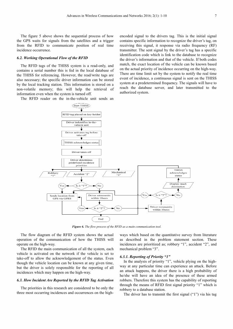
The figure 5 above shows the sequential process of how
the GPS waits for signals from the satellites and a trigger
from the RFID to communicate position of real time
incidence occurrence.
6.2. Working Operational Flow of the RFID
The RFID tags of the THISS system is a read-only, and
contains a serial number this is fed in the local database of
the THISS for referencing. However, the read/write tags are
also necessary; the specific driver information can be stored
by the local tracking station. This information is stored on a
non-volatile memory; this will help the retrieval of
information even when the system is turned off.
The RFID reader on the in-the-vehicle unit sends an
encoded signal to the drivers tag. This is the initial signal
contains specific information to recognize the driver’s tag, on
receiving this signal, it response via radio frequency (RF)
transmitter. The sent signal by the driver’s tag has a specific
identification code which is link to the database to recognize
the driver’s information and that of the vehicle. If both codes
match, the exact location of the vehicle can be known based
on the actual priority of incidence occurring on the high-way.
There are time limit set by the system to notify the real time
event of incidence, a continuous signal is sent on the THISS
system at a predetermined frequency. The signals will have to
reach the database server, and later transmitted to the
authorized system.
Figure 6. The flow process of the RFID as a main communication tool.
The flow diagram of the RFID system shows the actual
operation of the communication of how the THISS will
operate on the high-way.
The RFID the main communication of all the system, each
vehicle is activated on the network if the vehicle is set to
take-off to allow the acknowledgement of the status. Even
though the vehicle location can be known at any given time,
but the driver is solely responsible for the reporting of all
incidences which may happen on the high-way.
6.3. How Incident Are Reported by the RFID Tag Activation
The priorities in this research are considered to be only the
three most occurring incidences and occurrences on the high-
ways which based on the quantitative survey from literature
as described in the problem statement section. These
incidences are prioritized as; robbery “1”, accident “2”, and
mechanical problem “3”.
6.3.1. Reporting of Priority “1”
In the analysis of priority “1”, vehicle plying on the high-
way at any particular time can experience an attack. Before
an attack happens, the driver there is a high probability of
he/she will have an idea of the presence of these armed
robbers. Therefore this system has the capability of reporting
through the means of RFID first signal priority “1” which is
robbery to a database station.
The driver has to transmit the first signal (“1”) via his tag

8 Mamudu Hamidu: Use of RFID Technology as a Reporting Mechanism in Vehicle Tracking System
and robbery attack signal is sent on to the network. This will
show the exact location via coordinates at a particular radius.
By this means, the nearest patrol team or authorized security
force will response swiftly to prevent the incident from
happening. This priority stays confirmed after ten
seconds�� � 10�����.. However, if the driver retransmits a
signal from the RFID tag within the ten seconds �� �
10����� then the next priority is activated and transmitted on
the THISS system.
6.3.2. Reporting of Priority “2”
This priority is to report road accident or an unnecessary
speeding on the high-way where its difficulty to report such
incidences. This can be done by the driver in the accident
vehicle or most importantly by any passing vehicle. This
reporting is done in a time constraint of within ten seconds
from the reporting time of priority “1”. However, high impact
sensor can also compliment the reporting of this priority if it
is a serious accident. On the other hand, if it a less impact
accident, driver should be able to report within the next ten
seconds after priority “1” �0 � � � 10����� . After this
period, if there is no third signal sent by the driver, the
system will report.
6.3.3. Reporting of Priority “3”
This is the reporting of mechanical problem which is the
third most occurring incident on the high-way. The on-board
vehicle unit will report the incidence of mechanical problem
if and only if the driver transmit three separate signal within
20 seconds �10 � � � 20�����after the priority “1”. This
will help transport operators to be able to send new vehicle to
convey stranded passengers and drivers on the high-way and
also mechanics to repair major faults.
6.3.4. Destination Notification
This is to notify the THISS system that the vehicle has
reached its destination to allow the on-board vehicle unit to
go off. This also allows the acknowledgement of the tracking
station of vehicle’s arrival at its’ destination with coordinates
taken for event analysis.
The fig below is the sequence process of how the driver
uses his tag to communicate the real time event to the
database server.
Figure 7. The sequence diagram of communication from the driver to the server.
The micro controller chosen is AT 89S52, which serves as
the central command control of all this RFID based system
components namely; the GPS, RFID, and the GSM/GPRS
modules on the in-the-vehicle unit. It process includes when
to use the system, which components to be used and at what
time they should interact with each other. It is a
programmable part of the system where all units have to
access their commands. The micro controller has the
privilege to update all units status of hoe each should
response that is required to implement the in-the-vehicle unit.
6.3.5. Response of the RFID Based Vehicle Tracking
System
The response of the system is the legitimate to the flow of
how the in-the-vehicle unit communicates to the local data
server. This will aid authorize persons to take the appropriate

Advances in Wireless Communications and Networks 2016; 2(1): 1-10 9
action to forestall any of the three main priorities on the high-
way. In figure 8 shows a simple response of the Transport
High-way Integrated Security System (THISS).
Figure 8. The response diagram of the THISS.
Management phase (database): the management phase
contains functions of organizing driver’s information,
received data from the Base station (BS)/Subscriber station
(SSs) (tracking data) and GIS data (check-points).
6.3.6. The Flow Diagram for the GPS System of the
in-the-Vehicle Unit
Special radio signals from the satellites are received by the
GPS receiver, which further carries out mathematical
calculations on them.
Figure 9. The direct flow chart of GPS localization of vehicle.
For calculating the exact position, the GPS receiver should
know:
� Distance of the tracked device from each of the satellite.
� Rough location of the device to be tracked.
As mentioned earlier, GPS receivers calculate the distance
from the satellite on the basis of the time taken for the radio
waves to travel. To know this exact time, the clocks of the
satellites and the GPS receiver should be synchronized.
Satellites use an atomic clock while receivers use a quartz
clock. The quartz clock continuously resets itself [7]. The
receiver looks at all the incoming signals, and selects the
current time signal for location calculations. All the other
signals are aligned at a single point in space, by using this
time value as a reference. The receiver itself resets its clock
to the atomic clock value. Once this time value is known, and
the satellites are aligned, spheres are drawn around these
satellites based on the calculated distances that intersect at a
particular point. As the receiver continuously resets its clock
according to the atomic clock of the satellites, these distances
are accurate, and the intersecting point will give the exact
location of the device.
7. Conclusion
A better communication system suited for effective
reporting of incidences and occurrences on the highway is
proposed. The solution is wireless means of using RFID
technology combined with GPS, GSM and a database server
is defined in a general architecture. Therefore with the
increasing population plying the highway means more
incidences and occurrences are bound to happen. Therefore
this proposed technology will help reduce the menace. The
three major incidence claims thousands of lives, loss of
properties, waste of time in incurring more cost, and
reduction in the rich human resource base of the country
every year. The responses are done by knowing the exact
location on the high-way. Due to the complex nature of this
design, some future studies are to implement and simulate the
system to show how the RFID will response to
communication of the priorities.
References
[1] Shreenivas, J., M. S. Sutaone, and V. V. Badawe 2011. ‘Performance Improvement of GPS based Vehicle Tracking System using DGPS and Mobile Wi-Max’. IJCSET 1(8) 491-495
[2] Baburao, K., V. K. Raju, S. R. Srinivasa, A. V. Prabu, T. R. Appa, and Y. V. Narayana. 2014. GSM and GPS based vehicle location and tracking system. International Journal of Engineering Research and Applications (IJERA). Vol. 1, Issue 3, pp.616-625.
[3] Ning, Y., W. Zhong-qin, R. Malekian, W. Ru-chuan, and A. H. Abdulla. 2013. Design of Accurate Vehicle Location System Using RFID. Elektronika IR Elektrotechnika [Online] 19(8), 1392-1215.
[4] Ruijian, Z. 2013. A transportation security system applying RFID and GPS. Journal of Industrial Engineering and Management 6(1), 163-174.

10 Mamudu Hamidu: Use of RFID Technology as a Reporting Mechanism in Vehicle Tracking System
[5] Datta, T., Debdoot, S., Kumar, A., Dutta, A., Dasgupta, S., and Sarkar, S. K. 2007. Realization & Simulation of the Hardware for RFID system and its performance study. IET-UK International Conference on Information and Communication Technology in Electrical Sciences. 20-22, 2007. pp. 697-700. University, Chennai, Tamil.
[6] Datta, T., Debdoot, S., Kumar, A., Dutta, A., Dasgupta, S., and Sarkar, S. K. 2003. RFID based Airport Logistics Management. 3rd Innovative Conference on Embedded Systems, Mobile Communication & Computing (ICEMC2 2008), Infosys Mysore, Karnataka, India, 228-232.
[7] Casper, S. 2006. Garmin, GPS 60 navigator Owner’s Manual, March-2006. Available at: https://www.rei.com/media/97730477-6010-4217-9f62-6f5cd4693a40. Accessed 14May 2016.
[8] Jean-Marie, Z. 2002. GPS basics-Introduction to system Application overview, GPS-X-02007. Available at: http:// www.u-blox.com. Accessed 24 July 2016.
[9] Cardullo et al. 1973. "Transponder apparatus and system”, US Patent 3,713,148.
[10] Landt, J. 2001. “Shrouds of Time: The history of RFID", AIM, Inc.
[11] Bogdan C. Ionescu, “A Study of RFID Devices and Efficient Ways of Simulating RFID Systems with Maxwell Software”, Technical Articles for E-M Products, Ansoft.
[12] S. Basat, K. Lim, I. Kim, M. M. Tentzeris, J. Laskar, “Design and Development of a Miniaturized Embedded UHF RFID Tag for Automotive Tire Applications”, School of ECE, Georgia Institute of Technology, Atlanta, GA 30332-0250, USA
[13] Tikhov, Y. 2006. “Comments on ‘Antenna design for UHF RFID tags: A review and a practical application’,” IEEE Trans. Antennas Propag., vol. 54, p. 1906.
[14] Dinkar, A. S. and Shaikh, S. A., 2011. Design and implementation of Vehicle tracking system using GPS. Journal of Information Engineering and Applications, 1(3), pp. 1-7.
[15] Weinstein (2006), H., Bhatt, N., Mehta, H., & Dist-rajkot, T. (2014). RFID and GPS combination approach implementation in fisher boat tracking system. International Journal of
Computer Science and Information Technologies, 5(2), 1836-1838.
[16] Weinstein, R. 2005. “RFID: A Technical Overview and Its Application to the Enterprise,” IT Professional, Vol. 7, No.3, pp. 2733.
[17] Woodford, C. 2009. Accelerometers. Retrieved from http://www.explainthatstuff.com/accelerometers.html. [Accessed 29/10/2016]
[18] National Road Safety Commission (NRSC) 2010. Annual Report. National Road Safety Commission, Ghana. Retrieved from www.nrsc.gov.gh.
[19] Onatere-Ubrurhe, J. O. (2015). “Model Formulation for Predicting Future Highway Armed Robbery Incidents in Nigeria”. Available on: [http://www.iiste.org/Journals/index.php/DCS/article/viewFile/26630/27279]. Accessed: 3/12/2015.
[20] National Transportation Statistics 2015, available at http://www.bts.gov/ as of November 2015.
[21] Harvey, L. 2008. RFID Design Principles. ARTECH HOUSE. INC. Norwood. USA.
[22] Durani, H., Bhatt, N., Mehta, H. and Dist-rajkot, T., 2014. RFID and GPS combination approach implementation in fisher boat tracking system. International Journal of Computer Science and Information Technologies, 5(2), pp. 1836-1838.
[23] Cooper, D. E., Stanford, M., Kibble, K. A. and Gibbons, G. J., 2012. Additive manufacturing for product improvement at Red Bull Technology. Materials & Design, 41, pp. 226-230.
[24] Datta, T., De, A. and Bhattacharjee, A., 2013. RFID Model and Study Its Performances. International Journal of Computer Applications, 68(1).
[25] 8-bit Microcontroller with 8K Bytes In-System Programmable Flash 2008. Retrieved from: http://www.electroschematics.com/wp-content/uploads/2015/01/AT89S52-Datasheet.pdf. Accessed on: 29/10/2016.
[26] Atmel RFID Kits Overview 2015. Retrieved from: http://www.atmel.com/images/atmel-4980-rfid-kits-overview_application-note.pdf. Accessed on: 29/10/2016.