Embed Size (px)
Citation preview

Chapter 13Use of Nanostructured Coatingto Improve Heat Exchanger Efficiency
Antonino Bonanno, Mariarosa Raimondo and Michele Pinelli
Abstract This work investigates the potential of surface nano-coatings on the heattransfer surface of heat exchangers, in order to improve their overall efficiency interms of pressure drop and heat power exchanged. The work started from the con-sideration that, due to the increasingly strict international standards, the machineswill be provided with optimized engines with new and improved devices to reducethe exhaust emissions (liquid cooled EGR valves, new catalytic converters and DPFsystems) which reduce inevitably the space in the engine compartment. In this paperit is studied the feasibility of the coating processes and the adaptability of depositiontechniques to the industrial production process of cross flow heat exchanger fins. Theinnovative exchanger performance, investigated using dedicated test rigs, shows thatthe results are influenced by the coating technology.
13.1 Scientific and Industrial Motivations
Heat exchanger efficiency is one of themain concerns in trying to improve the overallefficiency of mobile off-road machines and industrial plants. Compact radiators playa fundamental role in temperature control of internal combustion engines (ICE)and hybrid drivelines. An improvement of this component could affect the globalefficiency of the machine. Typically, the problem is studied from a geometrical pointof view, using different production lines tomakefins geometries dedicated to improvethe heat exchange or to reduce the pressure drop. Heat exchanger optimization isneeded to obtain smaller, lighter, but at the same time more efficient radiators.
A. Bonanno (B)CNR-IMAMOTER, Istituto per le Macchine Agricole e Movimento Terra, Ferrara, Italye-mail: [email protected]
M. RaimondoCNR-ISTEC, Istituto di Scienza e Tecnologia dei Materiali Ceramici, Faenza, Ravenna, Italy
M. PinelliUniversità di Ferrara, Ferrara, Italy
© The Author(s) 2019T. Tolio et al. (eds.), Factories of the Future,https://doi.org/10.1007/978-3-319-94358-9_13
275
276 A. Bonanno et al.
In this paper, we propose to focus the attention on the possibility to change theperformance not only via geometrical modifications, but also considering new pro-duction processes to functionalize the heat exchanger surfaces, thus enabling tocustomize the performance based on the specific requests. Indeed, the laminar layerheight, which influences the ability to exchange heat and the pressure drop could bemodified by changing the surface functionalization while keeping the same geome-try. Therefore, the use of functionalized coating could improve the heat exchangerperformance, giving the possibility to develop new product families able to satisfythe market requests, especially for tailored (high value—high technological content)products. The use of functionalized coating (superhydrophobic and oleophobic) inheat exchanger has not been tested until now. Recently some studies dedicated tothe applicability of nanostructured coating on hydraulic piston pumps have beenpresented [1]. The structure of a nanoscale surfaces enables to modify its wettingand the fluid interaction. Thus, it is possible to reach high levels of repulsion againstwater (super-hydrophobicity) or oils/alcohols (oleophobicity).
This work studies the potential of a novel nanostructured coating, featuring super-hydrophobic and oleophobic behaviour, in providing better performance to the heatexchanger for fixed andmobile circuit. Different production technologieswere inves-tigated with the aim to further develop the currently most easily adaptable method-ology, i.e. hot brazing.
Moreover, a software tool was developed to optimize the heat exchanger geometryperformance, thus ensuring the best results in term of heat exchanger performanceregardless of its overall dimensions. The software tool is able to split the exchangerinto sub-domains having homogeneous boundary conditions and then simulates theperformance, both on the cold and hot side, in terms of theWHTC (WallHeat TransferCoefficient) and pressure drop, using CFD (Computational fluid dynamics) analysis.The basic idea is to simulate the entire radiator using sub-domains, considered as acombination of elements with series and parallel layout, as a function of the regionsto be simulated.
The chapter is organized as follows. Section 13.2 presents the state of the artregarding the ability to develop a nanostructured coating able to change the fluid sur-face interaction, specifically to reach a contact angle greater than 110 °C. Section 13.3proposes the overall approach to functionalize the whole heat exchanger withoutmodifying the actual construction methodology. Section 13.4 presents the developedmethodologies, tools, and prototypes. The testing and analysis of thermomechani-cal and corrosion analysis of functional layer is reported in Sect. 13.5. Finally, theconclusions are drawn in Sect. 13.6.
13.2 State of the Art
Although the heat exchangers are widely used both in mobile and fixed applications,to the best of our knowledge there are few examples of scientific works focused tothe same approach proposed in this paper. The effect of contact angle (or surface

13 Use of Nanostructured Coating to Improve Heat … 277
wettability) on the convective heat transfer coefficient has been studied and a cor-relation between the pressure drop reduction and heat transfer coefficient has beenfound considering a hydrophilic surface [2].
In a steam condensation application, the use of a hydrophobic coating hasimproved the overall heat coefficient of more than 10 times [3]. In air conditioningapplications, the pressure drop and the heat transfer have been studied considering ahydrophilic coating and a new correlation between heat, mass and momentum trans-fer has been proposed to describe the obtained results [4]. Furthermore, the use ofa hydrophilic coating has enhanced the heat transfer performance and has reducedthe pressure drop in a dehumidifying application [5]. The coating ability to promotefluid motion after the application of external forces was studied in the laminar fieldof motion [6] and in turbulent conditions [7, 8]. A relation between slip length andcontact angle was studied in [9].
Wettability is the ability of a liquid to maintain contact with a solid surface. Thewettability of the surface has a great influence on heat exchange, because it influ-ences the type of motion that is established between surface and fluid. The impactof wettability effect on heat transfer was studied in [10]. The effect of contact angle(or surface wettability) on the convective heat transfer coefficient in microchannelswas studied in [11], while a correlation between the contact angle and the wettingproperties is proposed in [12]. In none of the previous studies, however, the possibleconnection between the reduction of the friction between the fluid and the surface,by means of the nanostructured coating, and the increase in the heat exchange per-formance was investigated. About the oleophobic performance obtained using thetechnology proposed in this paper, the main literature can be found in [1, 13–17].
13.3 Problem Statement and Proposed Approach
Cross-flow heat exchangers are widely used in automotive and earthmoving machin-ery applications because they can transfer a great quantity of thermal power in arelative small volume. The need to cool process fluids is always present and becomescritical when there is the need to concentrate a big amount of power in increasinglysmall dimensions. This is the case, for example, of new hybrid solutions, whereto the thermal power generated by the ICE is added the thermal power developedby the driveline and the electric motor. This work is based on the hypothesis that,if heat transfer coefficient increases and friction power losses do not increase toomuch or even decrease, then it is then possible to transfer the same power by smallerdimensions or to transfer more thermal power by the same overall dimensions. Theproblem was addressed through five phases.
The first part of the work was dedicated to reduce the wettability of the sur-face thanks to the design and synthesis of coatings of various types, both organic andhybrid (organic-inorganic). In particular, we focused on themorphology of the nanos-tructure and on the surface chemistry that both have to be controlled and modulated(Sect. 13.4.1). In this context, the synthesis of ceramic oxides nanoparticles (Al2O3,
278 A. Bonanno et al.
ZrO2, etc.) was studied to form a stable colloids or nanosuspensions in differentmedia (i.e. alcohols or water). In this phase it was mandatory to have a high controldegree on phases, particle size and composition. Also specific synthetic approacheswere developed (i.e. sol-gel), involving particle nucleation directly from precursorspresent into the fluid, in the meantime avoiding particle precipitation and ensuring abetter control over physical variables of suspensions.
The second phase was the adaptation of laboratory deposition techniques tothe specific production process followed to make the brazed heat exchanger(Sect. 13.4.2). In this context, coating deposition by simple immersion techniques,such as dip-coating or spin-coating in controlled conditions, revealed to be suitableto produce homogeneous functional surfaces (turbolators), to easily control the layerthickness in the order of nanometers and to promote the formation of micro- andnanostructures. The main problem is related to the fact that the turbolators couldbe easily functionalized using the dip-coating, but they lost their superhydropho-bic/oleophobic performance after the brazing phase, necessary to assembly turbola-tors and fins in order to produce a complete heat exchanger. For this reason otherproduction techniques (e.g. pumping, suction) were experimented with the aim toinvestigate which of them could interfere as less as possible with the currently usedproduction technique.
The third phase was the development of a software tool able to simulate the heatexchanger, considering the different possible combinations of turbolators and finssurfaces (Sect. 13.4.3). The heat exchanger was decomposed in main portions inwhich the flow has some peculiar characteristics (mainly from the point of view ofboundary conditions applied). The final aim is to have a customized, yet flexible,tool able to predict the heat exchanger performance under different environmentalconditions and geometry dimensions, considering not only the possibility to optimizethe radiator by the fin geometry but also using the surface functionalization.
The assessment of functional performance of the obtained samples is the fourthphase of the work (Sect. 13.4.4). The setup of new measurement stations, in orderto have practical estimates of the behaviour of different surface coating, was alsotaken into consideration during this part of the work. For instance, a prototype withreduced dimension was used to monitor the pressure drop and the exchanged powerconsidering different nano-coating functionalized surface. The reasons groundingthe choice of the test cycles, foreseen for the functional performance tests, derivefrom the experience gained in functional characterization of the components at theexperimental stage and from the investigation of the relevant laboratory tests requiredby the applicable international standards.Akey factor at this stagewas the assessmentof changes or damages to the microstructure of the functionalized layers after thetest cycles.
The fifth and final phase was dedicated to the verification of new coating ability, inthe expected operative conditions, to assure the efficiency improvement (Sect. 13.5).A complete tribological, corrosion and mechanical characterization of functionallayers was performed.
13 Use of Nanostructured Coating to Improve Heat … 279
13.4 Developed Technologies, Methodologies and Tools
13.4.1 Development of Functional Layer
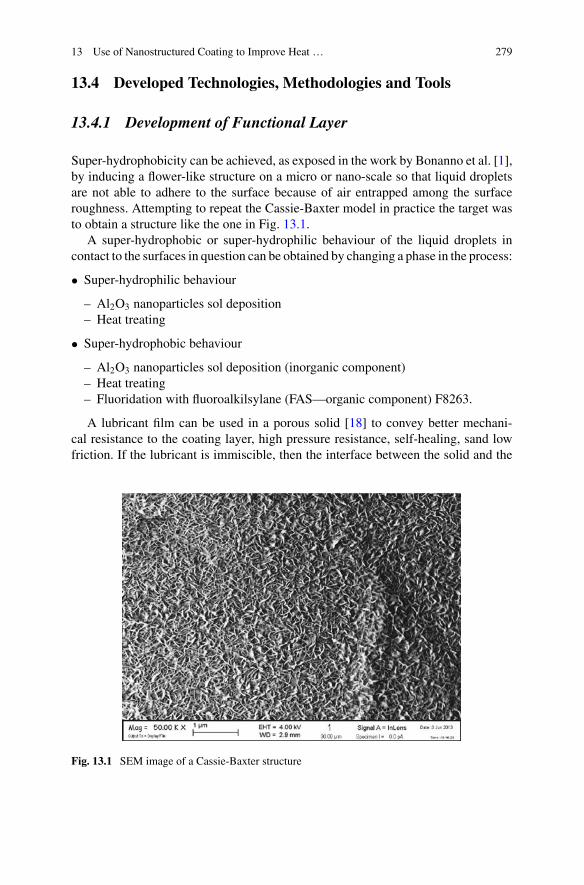
Super-hydrophobicity can be achieved, as exposed in the work by Bonanno et al. [1],by inducing a flower-like structure on a micro or nano-scale so that liquid dropletsare not able to adhere to the surface because of air entrapped among the surfaceroughness. Attempting to repeat the Cassie-Baxter model in practice the target wasto obtain a structure like the one in Fig. 13.1.
A super-hydrophobic or super-hydrophilic behaviour of the liquid droplets incontact to the surfaces in question can be obtained by changing a phase in the process:
• Super-hydrophilic behaviour
– Al2O3 nanoparticles sol deposition– Heat treating
• Super-hydrophobic behaviour
– Al2O3 nanoparticles sol deposition (inorganic component)– Heat treating– Fluoridation with fluoroalkilsylane (FAS—organic component) F8263.
A lubricant film can be used in a porous solid [18] to convey better mechani-cal resistance to the coating layer, high pressure resistance, self-healing, sand lowfriction. If the lubricant is immiscible, then the interface between the solid and the
Fig. 13.1 SEM image of a Cassie-Baxter structure
280 A. Bonanno et al.
immiscible liquid is no more solid but liquid, meaning that the lubricant interposedbetween solid and liquid reduces the friction.
13.4.2 Deposition Techniques
A surface must be optimised to keep repellency stable over time. In fact, keeping thefree energy of the solid/lubricant/liquid system as low as possible, it is possible tomake the liquid reside on the surface of the lubricant without replacing it, thus elim-inating the fixing points and obtaining extremely low sliding angles (super-repellentsurfaces). This is true also for liquids with very low surface tensions [19]. A quali-tative analysis showed the formation of the pinning effect, therefore the componentswere further functionalized with fluoridated lubricant FC-43 in order to obtain astable repellency. The functionalization of singular components of a heat exchangerimplicates a following bonding with further heat treatments that could damage thecoating, and so threaten the relative hydrophobic effect. The general coating tech-nique is the same described in the work by Bonanno et al. [1].
Three different coating techniques were developed and tested in this work:
• Functionalization by emptying. The functionalization by dip-coating (immersionin the solution) implies a strict dependence of the sol container on the heatexchanger dimensions. Besides the volume of sol to be produced must be some-times much greater than the volume to be filled in the heat exchanger. The empty-ing method works taking advantage of the same principle as the dip-coating one,namely the relative motion between solid surface and coating liquid. In this caseliquid moves to the solid which is steady whereas by dip-coating the solid movesand liquid is steady.
• Emptying by suction. This method consists in sucking the inner liquid, previouslyfilled in the heat exchanger, using a controlled volume variation container like asyringe. Since the optimal liquid evacuation velocity is 2 mm/s for both aluminasuspension solution and FAS solution, an appropriate piston velocity must beassessed. This method presents the non-negligible advantage of using the exactvolume of liquid necessary to fill the heat exchanger, furthermore, since both nano-particles solution and FAS can be used more than once to coat the solid surface,several heat exchangers can be treated with the same solutions.
• Emptying by pumping. This method is based on emptying the treated heatexchanger by pumping the chemical solutions out of it by using a peristaltic pumpwhich is volumetric (flow rate can be easily controlled by varying rotational speed)and suitable for low flow rate values (0–100 ml/min). The pump, activated by theelectrical supply, sucks the solution from the heat exchanger and sends it to thebottle that works as a recovery container. After having emptied the heat exchangerthe solution can be used again in another one.

13 Use of Nanostructured Coating to Improve Heat … 281
Fig. 13.2 Heat exchangersub-domains
13.4.3 Simulation of Heat Exchanger Performance
As previously described, a dedicated software toolwas developed to simulate the heatexchanger performance. By positioning on the XZ plane, the heat exchanger can bedivided into a number of basic elements, which have certain geometric characteristicsand fluid dynamics features. In particular, it can be distinguished an entrance area,an inner section and an output section of the cooling fluid. The same can be said forthe hot fluid. Preliminary analyses have highlighted a substantial independence ofthe results from the direction of the fluid: heat transfer coefficients and pressure dropwere slightly affected by the direction inwhich the transition plenum-interstices takesplace. This consideration leads to match subdomains that present the same geometricproperties regardless of the fluid dynamic condition in the subdomain. The resultwas to group the nine possible subdomains into four classes, in this way, only foursubdomains have been analysed as representative from each class. Summarizing, theadopted methodology does not simulate the coupling of one or more rows of hot sidefins with one or more cold side fins. Rather a small element of every single fin wasanalysed, by imposing on the single domain the boundary conditions that most likelywill occur during operation. Then, through a revision of the results that is performedby means of a spreadsheet, the subdomains are reconstructed in a virtual exchangerso as to have the characteristic of the global heat exchanger. The heat exchangeris thermo-fluid-dynamically reconstructed (Fig. 13.2) by spacing layers (in parallel)consisting of an element ofType 2 (shown in red) input, which has n elements in seriesType 5 (highlighted in blue) and then conclude with an element of Type 2 output. Inthis way, the types of simulation domains are cut without significantly reducing theaccuracy of the entire analysis. Initially, it was assumed that the size of the elementcould have an influence on the transfer coefficient due to the actual distribution oftemperature on the wall of the fins. However, by performing a preliminary analysison the influence of the size of the computational domain on the value of the heattransfer coefficient, there was a substantial independence from such a value.

282 A. Bonanno et al.
Table 13.1 Simulation conditions
Fluid Testedgeometries
Temperatures(°C)
Subdomains Velocities (m/s)
Air A0, A1, A2, A3,A4
20–40–60 Type 2–Type 5 2–4–6
Water-glycol P0–P2 60–80–120 Type 2–Type 5 0.2–0.4–0.6
Oil P0–P2 60–80–120 Type 2–Type 5 0.2–0.4– 0.6
Hot air P1–P3 120–160–200 Type 2–Type 5 4–6–8
For each designed geometry, we have identified two types of domain:
• Type 2, characterized by the presence of the inlet plenum that is used to simulatethe input section;
• Type 5, in which the plenum is absent because it represents the internal geometryof the heat exchanger.
A total amount of 5 geometries for fins (A0, A1, A2, A3, A4), 2 geometries forwater-glycol and oil channels (P0 and P2) and 2 geometries for the air channels (P1and P3) were analysed to assess the specific heat transfer coefficient and pressuredrop. The simulations performed were 180, as reported in Table 13.1.
13.4.4 Test Rig and Prototypes
During the work several prototypes were realized and a dedicated test rig was builtto properly test them. The test rig is shown in Fig. 13.3 and is composed of a servicepipeline that is connected to a proportional valve, i.e. a gate valve controlling the flowrate through the heat exchanger. Before the beginning of the tests, a heater controlsthe temperature of the inlet oil by heating the whole mass of oil contained in thetank, so that the oil has a high heat capacity to keep at a constant temperature duringthe tests. The air flow (the cold fluid) is driven by a fan, actuated by a hydraulicmotor, whose suction side is connected to the heat exchanger by a divergent duct.The oil temperatures (inlet and outlet), the oil flow, the air temperature, the oil andair pressures were all collected by a dedicated acquisition software, in order to haveall the measured values coming from different transducers. In particular, two flowmeters were installed to measure a wide range of volume flow rate: one has a fullscale of 10 l/min and the other of 300 l/min that can be activated separately by ballvalves placed upstream them.
All the measures were printed in a text file that can be imported into a post-processing software to examine and derive other physical quantities not directlymeasured. A control panel of the acquisition softwarewas developed from the groundup (both hardware and software) and used to monitor the working conditions of thetest rig.

13 Use of Nanostructured Coating to Improve Heat … 283
Fig. 13.3 Test rig for heat exchanger prototypes
Fig. 13.4 Type A heat exchanger a standard and b functionalized (right)
The first set of prototypes was developed by using the brazing technology toassemble the fin packs (Fig. 13.4) at about 600 °C, temperature at which the nanos-tructured coating would be irreparably damaged. To avoid this, the samples werefirst assembled and brazed, and then coated, according to one of the technologiespresented in Sect. 13.4.
Four different set of cross flow heat exchangers were realized as previously pre-sented and tested:
• Type A: 63 mm by 100 mm by 46 mm;• Type B: 94 mm by 93 mm by 200 mm;• Type C: 160 mm by 160 mm by 45 mm;• Bonded: 63 mm by 100 mm by 46 mm.
The choice of testing three different shapes and dimensions of heat exchang-ers is justified by the necessity to verify if scale effect would have amplified theirperformance differences.
In the Type A the lateral bowls were glued after the functionalization (by empting)of the fins pack as showed in Fig. 13.4 on the right. In the Types B and C the lateral
284 A. Bonanno et al.
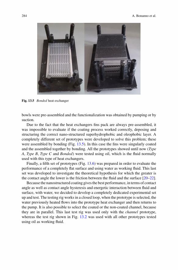
Fig. 13.5 Bonded heat exchanger
bowls were pre-assembled and the functionalization was obtained by pumping or bysuction.
Due to the fact that the heat exchangers fins pack are always pre-assembled, itwas impossible to evaluate if the coating process worked correctly, deposing andstructuring the correct nano-structured superhydrophobic and oleophobic layer. Acompletely different set of prototypes were developed to solve this problem; thesewere assembled by bonding (Fig. 13.5). In this case the fins were singularly coatedand the assembled together by bonding. All the prototypes showed until now (TypeA, Type B, Type C and Bonded) were tested using oil, which is the fluid normallyused with this type of heat exchangers.
Finally, a fifth set of prototypes (Fig. 13.6) was prepared in order to evaluate theperformance of a completely flat surface and using water as working fluid. This lastset was developed to investigate the theoretical hypothesis for which the greater isthe contact angle the lower is the friction between the fluid and the surface [20–22].
Because the nanostructured coating gives the best performance, in terms of contactangle as well as contact angle hysteresis and energetic interaction between fluid andsurface, with water, we decided to develop a completely dedicated experimental setup and test. The testing rig works in a closed loop, when the prototype is selected, thewater previously heated flows into the prototype heat exchanger and then returns tothe pump. It is also possible to select the coated or the non-coated channel, becausethey are in parallel. This last test rig was used only with the channel prototype,whereas the test rig shown in Fig. 13.2 was used with all other prototypes testedusing oil as working fluid.

13 Use of Nanostructured Coating to Improve Heat … 285
Fig. 13.6 Channel prototype
13.5 Testing and Validation of Results
Wettability of the samples treated with the techniques described in the previoussection were measured using diiodomethane (CH2I2 with a surface tension of 50.8mN/m) because of the impossibility to measure the water contact angle due toa complete water proofing of the surface of heat exchanger fins (Fig. 13.7). Theresults showed a contact angle of 133.1°±7.1° using the hybrid methodology and123.8°±6.6° using the lubricant. It can be noticed the good hydrophobicity achievedwith the hybrid method against the lubricant one on the liquid side fins. It was alsotested the possibility to achieve a direct functionalization through fluoridation only(agent F 8263). The assessment was done throughwater contact angle (WCA), CH2I2contact angle, and surface energy (SE) measurement. TheWCAwas 136.2°±34.7°,the CH2I2 contact angle was 70.9°±10.9° whereas the SE was 7.28±23.91 mN/m.From the results obtained, it comes out the nano-structuring necessity to achievesuper-hydrophobicity.
The heat resistance assessment of the coated layers was performed at three dif-ferent temperatures:
• Heating at 200 °C for 2 h—the results showed that the superhydrophobic-ity/oleophobicity is maintained;
• Heating at 300 °C for 2 h—still hydrophobic surfaces (spherical droplets) butlower slipping;
• Heating at 400 °C for 2 h—destruction of the organic component of the coating,with subsequent super-hydrophilicity.
The results confirm that the brazing production methodology currently employedis not compatible with the nanostructured superhydrophobic layer.
The test rig (see Sect. 13.4.4) was designed to supply prototype heat exchangerswith suitable thermal and hydraulic power to be dissipated. After measuring the threephysical quantities (volumeflow rate, static temperature and static pressure) thanks to

286 A. Bonanno et al.
Fig. 13.7 Experimental results: a standard heat exchanger pressure drop at different temperatures;b functionalized heat exchanger pressure drop at different temperatures; c standard heat exchangerheat transfer coefficient at different temperatures; d functionalized heat exchanger heat transfercoefficient at different temperatures
the sensors in the test rig and knowing the thermo-physical properties of the processfluid (hydraulic oil), it is possible to extrapolate the overall Darcy viscous frictionfactor f according to Eq. (13.1) and the overall heat transfer coefficient U accordingto Eq. (13.2).
f � 2 ∗ S2f ∗ �pm
ρ(t) ∗ Q2(13.1)
U � ρ(t) ∗ Q ∗ cp ∗ �TmSh ∗ �Tm ∗ F
(13.2)
Sf is the flow through surface at the inlet of the finned part of the heat exchanger,Δpm is the static pressure difference measured upstream and downstream the heatexchanger, ρ(t) is themass density of the fluid as a function of the instant temperatureof the fluid, Q is the volume flow rate of the fluid, cp is the specific heat capacity atconstant pressure of the fluid, ΔTm is the measured temperature difference betweenupstream and downstream the heat exchanger, Sh is the heat transfer surface of
13 Use of Nanostructured Coating to Improve Heat … 287
the finned part of the heat exchanger, ΔTml is the logarithmic mean temperaturedifference, F is a correction factor [23] depending on the shape of the heat exchangerand the way the fluids interact each other thermally and dynamically.
Four tests were carried out in two periods (or stages):
1. Test of Type A heat exchangers at three different inlet oil temperature condi-tions: 40, 65, 70 °C (two tests have been performed at 70 °C). For each workingcondition, volume flow rate was varied between 1 and 10 l/min with a step of1 l/min.
2. Test of Type A, Type B, TypeC andBonded in the updated test rig at three differentinlet oil temperature conditions: 50, 70, 85 °C.
The second stage corresponds to an evolution of the first one inasmuch the testrig has been improved and more attention paid to the data acquisition system. Thegeometrical correction factor F can be considered equal to one with good accuracyin each working condition.
The idea of a channel (basically a rectangular cross section pipe as showed inFig. 13.6 has been conceived to study the behaviour of water in contact to straightwalls that interact with liquid only through viscous friction.
The next subsections present the results of the main experiments.
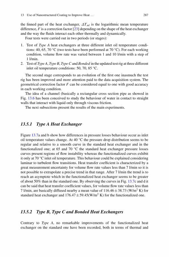
13.5.1 Type A Heat Exchanger
Figure 13.7a and b show how differences in pressure losses behaviour occur as inletoil temperature values change. At 40 °C the pressure drop distribution seems to beregular and relative to a smooth curve in the standard heat exchanger and in thefunctionalized one; at 65 and 70 °C the standard heat exchanger pressure lossescurves present regions of flow instability whereas the functionalized curves exhibitit only at 70 °C inlet oil temperature. This behaviour could be explained consideringlaminar to turbulent flow transitions. Heat transfer coefficient is characterized by agreat measurement uncertainty for volume flow rate values less than 7 l/min so it isnot possible to extrapolate a precise trend in that range. After 7 l/min the trend is toreach an asymptote which in the functionalized heat exchanger seems to be greaterof about 50% than in the standard one. By observing the curves in Fig. 13.7c and d itcan be said that heat transfer coefficient values, for volume flow rate values less than7 l/min, are basically diffused nearby a mean value of 116.46±38.73 (W/m2 K) forstandard heat exchanger and 176.47±59.45(W/m2 K) for the functionalized one.
13.5.2 Type B, Type C and Bonded Heat Exchangers
Contrary to Type A, no remarkable improvements of the functionalized heatexchanger on the standard one have been recorded, both in terms of thermal and
288 A. Bonanno et al.
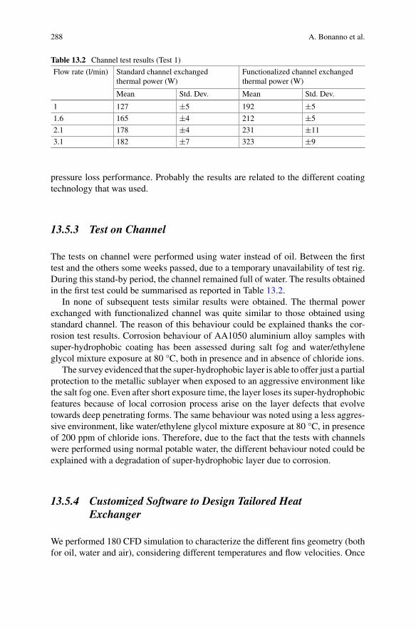
Table 13.2 Channel test results (Test 1)
Flow rate (l/min) Standard channel exchangedthermal power (W)
Functionalized channel exchangedthermal power (W)
Mean Std. Dev. Mean Std. Dev.
1 127 ±5 192 ±5
1.6 165 ±4 212 ±5
2.1 178 ±4 231 ±11
3.1 182 ±7 323 ±9
pressure loss performance. Probably the results are related to the different coatingtechnology that was used.
13.5.3 Test on Channel
The tests on channel were performed using water instead of oil. Between the firsttest and the others some weeks passed, due to a temporary unavailability of test rig.During this stand-by period, the channel remained full of water. The results obtainedin the first test could be summarised as reported in Table 13.2.
In none of subsequent tests similar results were obtained. The thermal powerexchanged with functionalized channel was quite similar to those obtained usingstandard channel. The reason of this behaviour could be explained thanks the cor-rosion test results. Corrosion behaviour of AA1050 aluminium alloy samples withsuper-hydrophobic coating has been assessed during salt fog and water/ethyleneglycol mixture exposure at 80 °C, both in presence and in absence of chloride ions.
The survey evidenced that the super-hydrophobic layer is able to offer just a partialprotection to the metallic sublayer when exposed to an aggressive environment likethe salt fog one. Even after short exposure time, the layer loses its super-hydrophobicfeatures because of local corrosion process arise on the layer defects that evolvetowards deep penetrating forms. The same behaviour was noted using a less aggres-sive environment, like water/ethylene glycol mixture exposure at 80 °C, in presenceof 200 ppm of chloride ions. Therefore, due to the fact that the tests with channelswere performed using normal potable water, the different behaviour noted could beexplained with a degradation of super-hydrophobic layer due to corrosion.
13.5.4 Customized Software to Design Tailored HeatExchanger
We performed 180 CFD simulation to characterize the different fins geometry (bothfor oil, water and air), considering different temperatures and flow velocities. Once
13 Use of Nanostructured Coating to Improve Heat … 289
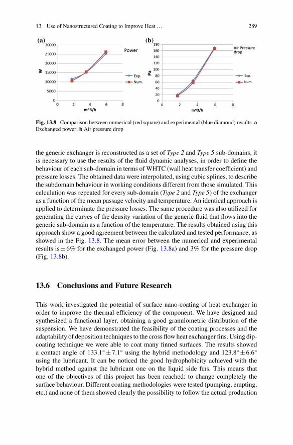
Fig. 13.8 Comparison between numerical (red square) and experimental (blue diamond) results. aExchanged power; b Air pressure drop
the generic exchanger is reconstructed as a set of Type 2 and Type 5 sub-domains, itis necessary to use the results of the fluid dynamic analyses, in order to define thebehaviour of each sub-domain in terms ofWHTC (wall heat transfer coefficient) andpressure losses. The obtained data were interpolated, using cubic splines, to describethe subdomain behaviour in working conditions different from those simulated. Thiscalculation was repeated for every sub-domain (Type 2 and Type 5) of the exchangeras a function of the mean passage velocity and temperature. An identical approach isapplied to determinate the pressure losses. The same procedure was also utilized forgenerating the curves of the density variation of the generic fluid that flows into thegeneric sub-domain as a function of the temperature. The results obtained using thisapproach show a good agreement between the calculated and tested performance, asshowed in the Fig. 13.8. The mean error between the numerical and experimentalresults is±6% for the exchanged power (Fig. 13.8a) and 3% for the pressure drop(Fig. 13.8b).
13.6 Conclusions and Future Research
This work investigated the potential of surface nano-coating of heat exchanger inorder to improve the thermal efficiency of the component. We have designed andsynthesized a functional layer, obtaining a good granulometric distribution of thesuspension. We have demonstrated the feasibility of the coating processes and theadaptability of deposition techniques to the cross flow heat exchanger fins. Using dip-coating technique we were able to coat many finned surfaces. The results showeda contact angle of 133.1°±7.1° using the hybrid methodology and 123.8°±6.6°using the lubricant. It can be noticed the good hydrophobicity achieved with thehybrid method against the lubricant one on the liquid side fins. This means thatone of the objectives of this project has been reached: to change completely thesurface behaviour. Different coating methodologies were tested (pumping, empting,etc.) and none of them showed clearly the possibility to follow the actual production

290 A. Bonanno et al.
methodology (by brazing) of cross flow heat exchanger, which should be probablymodified.
The influence of the new superhydrophobic and oleophobic surface on the heatexchanger behaviour was studied thanks to a dedicated test rig. The results showthat, for the Type A heat exchanger, the heat transfer coefficient values, for vol-ume flow rate values less than 7 l/min, are basically diffused nearby a meanvalue of 116.46±38.73 (W/m2 K) for standard heat exchanger and 176.47±59.45(W/m2 K) for the functionalized one. The same results were not found in theother heat exchanger (Type B, Type C, Bonded) probably due to the different coatingmethodology used. A last test was performed using water instead of oil and consid-ering a different heat exchanger geometry (channel). In this last test the first set ofresults obtained show a good improvement of heat exchange coefficient (≈+20%),but the test performed after some weeks on the same component did not confirm thistrend. The results become clearer after the corrosion test, were the survey evidencedthat the super-hydrophobic layer is able to offer just a partial protection to themetallicsublayer when exposed to an aggressive environment like the salt fog one. Even aftershort exposure time, the layer loses its super-hydrophobic features because of localcorrosion process arise on the layer defects that evolve towards deep penetratingforms. Finally, a dedicated modular software was developed. The results obtainedcomparing the experimental results with the numerical one show good agreementconsidering both the heat exchanger power and pressure drop. Further results relatedto this work are presented in the papers [24–30].
Finally, the exploitation of the scientific results led to the submission and approvalof a research project titled HEAT (nano coated Heat ExchAnger with improvedThermal performances) funded under the call POR-FESR 2014–2020 of RegioneEmilia Romagna. This project is coordinated by ISTEC-CNR in cooperation withFIRA spa and COMEX EUROPE srl.
Acknowledgements This work has been funded by the Italian Ministry of Education, UniversitiesandResearch (MIUR) under the Flagship Project “Factories of the Future - Italy” (Progetto Bandiera“La Fabbrica del Futuro”) [31], Sottoprogetto 2, research projects “CustomizedHeat exchangerwithImproved Nano-coated surface for earth moving machines Applications” (CHINA) and “ThermallyImproved Heat Exchangers prototypes with Superhydrophobic Internal Surfaces: new assemblyprocedures and materials” (THESIS).
The authors express their gratitude to the following researcher, for the precious and effectivecollaboration,withoutwhich all thisworkwould not be possible: Eng.GiuseppeRizzo, Eng.GiorgioPaolo Massarotti, Eng. Luca Pastorello, Dr. Maria Giulia Faga, Dr. Giovanna Gautier, Dr. FedericoVeronesi, Dr. Magda Blosi, Dr. Aurora Caldarelli, Dr. Giulio Boveri, Mrs. Guia Guarini.
The authors would like to thank for his indispensable technical andmethodological contribution,FIRA S.p.A., which developed the heat exchangers and gave the necessary support to perform allthe tests and to develop the different prototypes.
This work would not have been possible without the foresight of Prof. Roberto Paoluzzi, inmemory of whom this paper was written.

13 Use of Nanostructured Coating to Improve Heat … 291
References
1. Bonanno A, Raimondo MR, Zapperi S (2019) Surface nano-structured coating for improvedperformance of axial piston pumps. In: Tolio T, Copani G, Terkaj W (eds) Factories of thefuture. Springer
2. Rosengarten G, Cooper-White J, Metcalfe G (2006) Experimental and analytical study of theeffect of contact angle on liquid convective heat transfer in microchannels. Int J Heat MassTrans 49(21)
3. Lara JR, Holtzapple MT (2011) Experimental investigation of dropwise condensation onhydrophobic heat exchanger. Part II: effect of coatings and surface geometry. Desalination280:363–369
4. Sheng Y, Quing-Ding W (2006) Experimental study on physical mechanism of drag reductionof hydrophobic materials in laminar flow. Chin Phys Lett 23(6):1634
5. Xiaokui M, Ding G, Zhang Y,Wang K (2009) Airside characteristics of heat, mass transfer andpressure drop for heat exchangers of tube-in hydrophilic coating wavy fin under dehumidifyingconditions. Int J Heat Mass Transf 52:4358–4370
6. Jiaguo Y, Xiujian Z, Qingnan Z, Gao W (2001) Preparation and characterization of super-hydrophilic porous TiO2 coating films. Mater Chem Phys 68:253–259
7. Rothstein PJ (2010) Slip on Superhydrophobic Surfaces. Annu Rev Fluid Mech 42:89–109.https://doi.org/10.1146/annurev-fluid-121108-145558
8. Martell MB, Rothstein JP, Perot JB (2010) An analysis of superhydrophobic turbulent dragreduction mechanisms using direct numerical simulation. Phys Fluids (22), 065102. AmericanInstitute of Physics, https://doi.org/10.1063/1.3432514
9. Bsushan B, Wang Y, Maali A (2009) Boundary slip study on hydrophilic, hydropho-bic, and superhydrophobic surfaces with dynamic atomic force microscopy. Langmuir25(14):8117–8121. https://doi.org/10.1021/la900612s
10. Choi C, Moohwan K (2011) Wettability effects on heat transfer, two phase flow, phase changeand numerical modeling. Ahsan A (ed) InTech. https://doi.org/10.5772/19512
11. Rosengarten G, Cooper-White J, Metcalfe G (2010) Experimental and analytical study of theeffect of contact angle on liquid convective heat transfer in microchannels. Int J Heat MassTransf 49:4161–4170
12. Liu K, Yao X, Jiang L (2010) Recent development in bio-inspired special wettability. ChemSoc Rev 39:3240–3255. https://doi.org/10.1039/b917112f
13. Tuteja A, Choi W, Mabry JM, McKinley GH, Cohen RE (2007) Designing super-oleophobicsurfaces. Science 318:1618–1622. https://doi.org/10.1126/science.1148326
14. Bhushan B (2011) Biomimetic inspired surfaces for drag reduction and oleophobicity/philicity.Beilstein J Nanotech 2:66–68. https://doi.org/10.3762/bjnano.2.9
15. Rimondo M, Blosi M, Bezzi F, Mingazzini C (2011) Metodo per il Trattamento di Super-fici Ceramiche per Conferire alle Stesse una Elevata Idrofobicità e Oleofobicità. PatentRM2011A000104
16. Raimondo M, Blosi M, Bezzi F, Mingazzini C (2012) Metodo di Trattamento di Super-fici Metalliche per Conferire alle Stesse una Elevata Idrofobicità ed Oleofobicità. PatentRM2012A000291
17. RaimondoM (2012) Making super-hydrophobic building materials: static and dynamic behav-ior of nanostructured surface. In: IV ICC4 international ceramic conference, Chicago (USA),July 14–19 2012
18. Wong TS, Kang SH, Tang SK, Smythe EJ, Hatton BD, Grinthal A, Aizenberg J (2011)Bioinspired self-repairing slippery surfaces with pressure-stable omniphobicity. Nature477(7365):443–447. https://doi.org/10.1038/nature10447
19. Vogel N, Belisle R, Hatton B,Wong T, Aizenberg J (2013) Transparency and damage toleranceof patternable omniphobic lubricated surfaces based on inverse colloidal monolayers. NatCommun 4:2176. https://doi.org/10.1038/ncomms3176
20. Ingebrigtsen T, Toxvaerd S (2007) Contact angles of Lennard-Jones liquids and droplets onplanar surfaces. J Phys Chem C 111:8518

292 A. Bonanno et al.
21. Hong SD, Ha MY, Balachandar S (2009) Static and dynamic contact angles of water dropleton a solid surface using molecular dynamics simulation. J Coll Interf Sci 339:187
22. Park JY, Ha MY, Choi HJ, Hong SD, Yoon HS (2011) A study on the contact angles of a waterdroplet on smooth and rough solid surfaces. J Mech Sci Technol 25:323
23. Kakaç S, Liu H (1998) Heat exchangers selection, rating and thermal design. CRC Press LLC24. PastorelloL,BonannoA (2015)Application ofNano-structured coatings to heat transfer surface
of heat exchangers. In: The fourteenth scandinavian international conference on fluid power,May 20–22, 2015, Tampere, Finland
25. Paoluzzi R,BonannoA, Ferrari C,MartelliM (2014) Procedure for hydraulic oil heat exchangerperformance improvement through integrated CFD analysis. Int J Fluid Power 15(3):169–180
26. Raimondo M, Blosi M, Caldarelli A, Guarini G, Veronesi F (2014) Wetting behavior andremarkable durability of amphiphobic aluminum alloys surfaces in a wide range of environ-mental conditions. Chem Eng J 258:101–109. https://doi.org/10.1016/j.cej.2014.07.076
27. Caldarelli A, Raimondo M, Veronesi F, Boveri G, Guarini G (2015) Sol–gel route for thebuilding up of superhydrophobic nanostructured hybrid-coatings on copper surfaces. Surf CoatTechnol 276:408–415. https://doi.org/10.1016/j.surfcoat.2015.06.037
28. Motta A, Cannelli O, Boccia A, Zanoni R, Raimondo M, Caldarelli A, Veronesi F (2015) Amechanistic explanation of the peculiar amphiphobic properties of hybrid organic−inorganiccoatings by combining XPS characterization and DFT modeling. ACS Appl Mater Interfaces7:19941–19947. https://doi.org/10.1021/acsami.5b04376
29. Malavasi Veronesi F, Caldarelli A, Zani M, Raimondo M, Marengo M (2016) Is a knowledgeof surface topology and contact angles enough to define the drop impact outcome? Langmuir32:6255–6262. https://doi.org/10.1021/acs.langmuir.6b01117
30. Raimondo M, Veronesi F, Boveri G, Guarini G, Motta A, Zanoni R (2017) Superhydrophobicproperties induced by sol-gel routes on copper surfaces. Appl Surf Sci 422:1022–1029. https://doi.org/10.1016/j.apsusc.2017.05.257
31. TerkajW, Tolio T (2019) The Italian flagship project: factories of the future. In: Tolio T, CopaniG, Terkaj W (eds) Factories of the future. Springer
Open Access This book is licensed under the terms of the Creative Commons Attribution 4.0International License (http://creativecommons.org/licenses/by/4.0/), which permits use, sharing,adaptation, distribution and reproduction in any medium or format, as long as you give appropriatecredit to the original author(s) and the source, provide a link to the Creative Commons licence andindicate if changes were made.
The images or other third partymaterial in this bookare included in the book’sCreativeCommonslicence, unless indicated otherwise in a credit line to the material. If material is not included in thebook’s Creative Commons licence and your intended use is not permitted by statutory regulation orexceeds the permitted use, you will need to obtain permission directly from the copyright holder.


![[Mariarosa Dalla Costa Selma James] the Power of(Bookos.org)](https://img.pdfslide.us/doc/110x75/577cd6ab1a28ab9e789cee8c/mariarosa-dalla-costa-selma-james-the-power-ofbookosorg.jpg)