Embed Size (px)
Citation preview
Lasers in Manufacturing Conference 2015
Use of inline coherent imaging for laser welding processes: Process control and beyond
Thibault Bautzea*, Rüdiger Mosera, Matthias Strebela, Markus Kogel-Hollacherb
aPrecitec GmbH & Co. KG, Draisstr. 1, 76571 Gaggenau, Germany bPrecitec Optronik GmbH, Schleussnerstr. 54, 63263 Neu-Isenburg, Germany
Abstract
The introduction of inline coherent imaging technologies as a sensor for the laser materials processing is accompanied by the integration into several applications. One of these is the measurement of the depth of the vapor capillary for laser welding applications, now allowing to keep record of the welding depth with an accuracy of micrometers and a sub millisecond temporal resolution. The broader achievement is the closed-loop control of the welding depth that was not available in industrial environments till now due to the lack of an adequate sensor. Further use includes the acquisition of 3D images around the laser process itself, allowing for coaxial integration of pre- and post-process sensors. These applications are demonstrated by using the In-Process Depth Meter (IDM).
Keywords: laser welding; process monitoring; process control; low-coherence interferometry; sensor technology; penetration depth
1. Introduction
Since the invention of the laser, it has rapidly evolved in terms of technical benchmarks and applications. A huge step was made by using the laser light as a tool for materials processing, opening the doors to a wide set of new machine types. The focus of new developments shifted over the time: having started with the laser itself, efforts were put into the design of processing optics enabling new processes. Today, the most recent improvements are achieved by using high complex sensor- and software-solutions. Thus, the demand for new sensor technologies is more relevant than ever.
* Corresponding author. Tel.: +49 7225 684-567; fax: +49 7225 684-900.
E-mail address: [email protected].
On the other hand, the need for perfected processes, innovative material mixes and reduced error tolerances require a better understanding for what happens inside the laser welding process. Numerous investigations deal with the simulation of the vapor capillary (keyhole) behavior. Even though high speed imaging technologies exist since the beginnings, its small dimensions and its high-frequency dynamics make it impossible to continuously monitor the keyhole in an industrial environment.
This paper illustrates the applications of the inline coherent imaging for laser welding tasks. The first part summarizes the current state of the art for sensors, data processing and available measures. In a second step, the sensor technology itself will be presented. The third part covers the tested sensor applications, starting from laboratory implementations and ending with an outlook of upcoming solutions.
1.1. State of the art for laser welding process monitoring and control
The laser welding process can be seen as the interaction of the laser beam and the welded workpiece. Even this very limited representation is of complex nature: the laser needs to hit the workpiece at the right position, the laser needs to have the right power density and the resulting seam needs to fulfill the given requirements in term of appearance and steadiness. In general, sensors can be classified as pre-, in- or post-process sensors and can be used for monitoring, control or both.
The domain of pre-process sensors primarily deals with the acquisition of the joint position relatively to the tool center point (TCP) and is mostly image based. Common approaches use laser triangulation or grey scale image analysis. In both cases, a following data processing extracts the joint position and calculates a displacement vector for linear axes, a robot or similar. Recent developments also allow the adaption of the laser power density as a function of space and time to a given joint geometry (Weberpals, 2015). Due to the large workspace of laser scanners and the resulting complexity for the joint geometry, pre-process sensor solutions only slowly begin to arise for these. (Dorsch, 2015, Vogl, 2014).
A very wide field of sensor technologies exists for the in-process application. The major role of these sensors is the acquisition of signals that correlate with the resulting properties of the weld seam or, in simple words, its quality. A subset of sensors is also capable to control process properties, aiming to maintain a stable process quality. Here, one key measure needs to be named for monitoring and controlling the process: the depth of the keyhole. It is the best indicator for the attained penetration depth and can be directly influenced by varying the applied laser power.
Most in-process monitoring solutions rely on the use of photodiodes that acquire electromagnetic radiation in different spectral bands, e.g. heat radiation, laser back-reflection or visible emissions. The information is given by the signal amplitude or a derivative of it, such as a frequency transformation or wavelet transformation. Still, no absolute measures, e.g. the penetration depth or seam width, are acquired. The quality assessment is based on the comparison with defined signal sequences and therefore requires laser welds in advance with stable seam qualities and defined process parameters. Correlations between signal levels and the penetration depth can be made, but are only valid around the operating point. The slightest changes of process or material parameters can lead to erroneous classifications and therefore disallow this method for small batches. Nevertheless, the simplicity of the principle allows an easy integration and compatibility with most laser welding processes. In literature, several publications discuss the use of photodiodes for monitoring purposes (Eriksson, 2009).
Due to the absence of a direct relation between signal levels and seam properties, the use of photodiodes for controlling the laser power is limited. Model-based controllers, often combined with neural networks or other self-learning algorithms, are used to perform this task. Their complexity and sensitivity prohibit their use in industrial environments.
The image acquisition of the laser interaction with the workpiece reveals a wide set of measures directly related to the welding process. Geometrical properties of the meltpool and the keyhole can be extracted and used for quality assurance or control purposes. Further details can be revealed by using additional illumination, laser triangulation or sensors sensitive in the near infrared spectral domain. Due to the lack of 3D information for the keyhole, none of the possible measures are analytically related to the penetration depth. However, advanced optical setups separate the s- and p-polarized thermal radiations of the keyhole front, allowing to calculate its slope and to approximate its depth (Weberpals, 2011).
Several implementations have been tested to use image features to closed-loop control the laser welding process. Common measures are the shape of the keyhole (Bardin, 2005) or the full penetration hole (Blug, 2011), entered into PID-, two-level or similar controllers. More elaborated approaches combine images with the information gathered from photodiodes and integrate dimensionality-reduction and multi-dimensional classification algorithms in order to deal with the data complexity (Stork gen. Wersborg, 2009). All approaches can be used to control the process, but they cannot guarantee to maintain a predefined welding depth if non-observable process parameters vary.
Outside of the industrial use, other in-process sensors are worth to be mentioned. The use of X-ray technology allows to visualize the shape of the keyhole and hence to determine its depth and length. Other defects, such as internal pores, can also be made visible (Abt, 2011). The use of airborne or structure borne acoustic sensors also reveals relevant properties, but is limited to high-frequency effects, such as keyhole or plasma plume oscillations or discrete events such as the full penetration (Huang, 2009). The acquisition of the process emissions with a spectrometer reveals material dependent spectral signatures that can be used for monitor or control purposes (Konuk, 2011). Several other approaches are compared in the literature (Shao, 2005, Norman, 2007, Purtonen, 2014).
The aim of post-process sensors is to determine the geometry of the weld seam and record any kind of defects, such as visible or internal pores, cracks or lack of fusion. Industrial solutions mostly rely on the use of laser triangulation sensors and grey scale image analysis. Welding systems with fixed optics can be directly equipped with these sensors (online measurement), whereas scanning optics require an adjacent inspection (offline measurement). The visible defect size is limited to the resolution of the used optical sensor and to their presence on the surface. Common detectable defect sizes are in the range of 0.1 mm.
Other technologies also allow the detection of inlaying defects. As a wide range of these non-destructive testing means exists for weld seams, only some may be named: eddy current sensors (Bautze, 2011), ultrasonic testing or thermography are used in industrial applications.
1.2. The demand for technological improvements
Although several kinds of sensor technologies are available for monitoring and controlling the laser welding process, their use is limited to specific applications.
Due to the absence of an easy measure of the true penetration depth, the definition of welding process parameters such as the laser power or ideal focal position is done empirically with massive utilization of cross sections. A tool allowing to have an easy access to the achieved penetration depth would shorten this process initialization time. The additional closed-loop control of the laser power without preliminary definition of an ideal laser power was demonstrated on several places, but lacks of robustness and versatility.
Pre-process control finds its way into some applications using scanning optics, whereas the online post-process monitoring is limited to fixed welding optics. An improvement could be achieved by integrating post-process sensors into scanning optics or by developing in-process sensors able to detect defects nowadays monitored with post-process sensors.
2. Use of low-coherence interferometry in laser material processing
Laser welding is a highly dynamic process, requiring a sensor with high temporal and spatial resolution. A further drawback is the presence of intense process emissions and steep temperature gradients. These circumstances can be handled by using optical sensor technologies such as low-coherence interferometry. The use of this method in laser applications has risen in the last years. Since its first appearance in 2008 (Schürmann, 2008), application examples were shown for laser cutting (Schneider, 2015), selective laser melting (Neef, 2014), laser micro machining (Schmitt, 2012), laser drilling (Webster, 2010) and laser welding (Kogel-Hollacher, 2014, Bautze, 2014, Lohaus, 2010). For the latter, a huge potential is foreseen (Kogel-Hollacher, 2014).
2.1. Measuring principle
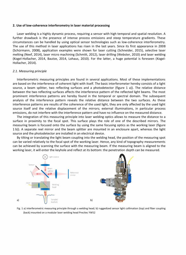
Interferometric measuring principles are found in several applications. Most of these implementations are based on the interference of coherent light with itself. The basic interferometer hereby consists of a light source, a beam splitter, two reflecting surfaces and a photodetector (figure 1 a)). The relative distance between the two reflecting surfaces affects the interference pattern of the reflected light beams. The most prominent interference patterns are hereby found in the temporal or spectral domain. The subsequent analysis of the interference pattern reveals the relative distance between the two surfaces. As these interference patterns are results of the coherence of the used light, they are only affected by the used light source itself and the relative displacement of the mirrors; external illuminations, in particular process emissions, do not interfere with the interference pattern and have no influence on the measured distance.
The integration of this measuring principle into laser welding optics allows to measure the distance to a surface in proximity to the focal spot. This surface plays the role of one of the described mirrors. The measuring beam is focused onto the surface by using the same focusing optics as the working laser (figure 1 b)). A separate reel mirror and the beam splitter are mounted in an enclosure apart, whereas the light source and the photodetector are installed in an electrical device.
By tilting or translating the light beam coupling into the welding head, the position of the measuring spot can be varied relatively to the focal spot of the working laser. Hence, any kind of topography measurements can be achieved by scanning the surface with the measuring beam. If the measuring beam is aligned to the working laser, it will enter the keyhole and reflect at its bottom: the penetration depth can be measured.
a) b)
Fig. 1 a) interferometric measuring principle through a welding head; b) ruggedized sensor light collimation (top) and fiber coupling
(back) mounted on a modular laser welding head Precitec YW52
2.2. Sensor characteristics
All of the characteristics of the In-Process Depth Meter (IDM) were designed to meet the requirements of a continuous monitoring and control of the keyhole depth. In order to deal with the discrepancy of possible high frequent keyhole oscillations and low frequent changes of the penetration depth, the raw data is acquired with a high sample rate (70 kHz) and subsequently filtered by different means. The resulting signal corresponds to a penetration depth as it would be measured with cross sections.
The measuring range covers 14 mm, although the relevant penetration depths are in the range of less than 10 mm. The depth resolution is less than one micrometer and hereby sufficient to acquire any kind of keyhole depth variations.
The raw and processed measurement data, as well as other signal characteristics, are made available via analog outputs, the PLC-compatible RS422 connection or the graphical user interface running on a PC. The described sensor was used for all of the following application examples.
3. Application examples
In its basic configuration, the In-Process Depth Meter is a pure distance measuring device whose measuring range is superimposed or adjacent to the focal spot of a laser welding head. For the following application examples, it was partially equipped with additional hardware and data processing to allow for process monitoring, process control and pre- and post-process imaging.
3.1. Process development
The acquisition and understanding of raw measurement data reveals a multiplicity of process properties that cannot be acquired online through other sensors. Apart from the absolute penetration depth itself, material properties, keyhole stability and its shape, welding mode, as well as correlations to the presence of inlaying pores can be observed (Boley, 2015).
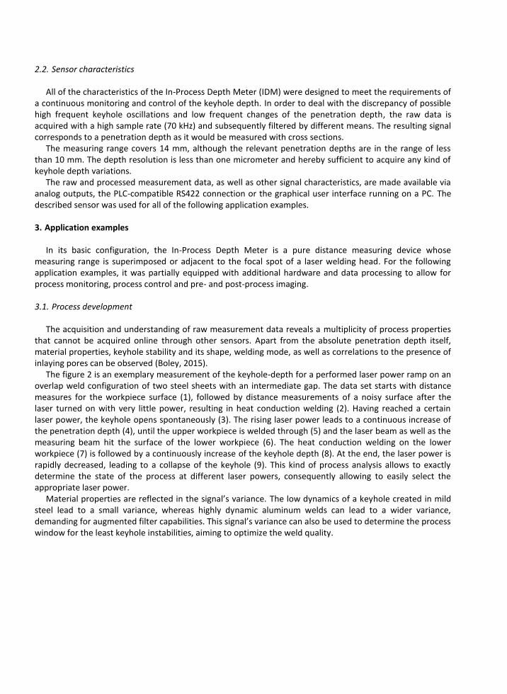
The figure 2 is an exemplary measurement of the keyhole-depth for a performed laser power ramp on an overlap weld configuration of two steel sheets with an intermediate gap. The data set starts with distance measures for the workpiece surface (1), followed by distance measurements of a noisy surface after the laser turned on with very little power, resulting in heat conduction welding (2). Having reached a certain laser power, the keyhole opens spontaneously (3). The rising laser power leads to a continuous increase of the penetration depth (4), until the upper workpiece is welded through (5) and the laser beam as well as the measuring beam hit the surface of the lower workpiece (6). The heat conduction welding on the lower workpiece (7) is followed by a continuously increase of the keyhole depth (8). At the end, the laser power is rapidly decreased, leading to a collapse of the keyhole (9). This kind of process analysis allows to exactly determine the state of the process at different laser powers, consequently allowing to easily select the appropriate laser power.
Material properties are reflected in the signal’s variance. The low dynamics of a keyhole created in mild steel lead to a small variance, whereas highly dynamic aluminum welds can lead to a wider variance, demanding for augmented filter capabilities. This signal’s variance can also be used to determine the process window for the least keyhole instabilities, aiming to optimize the weld quality.
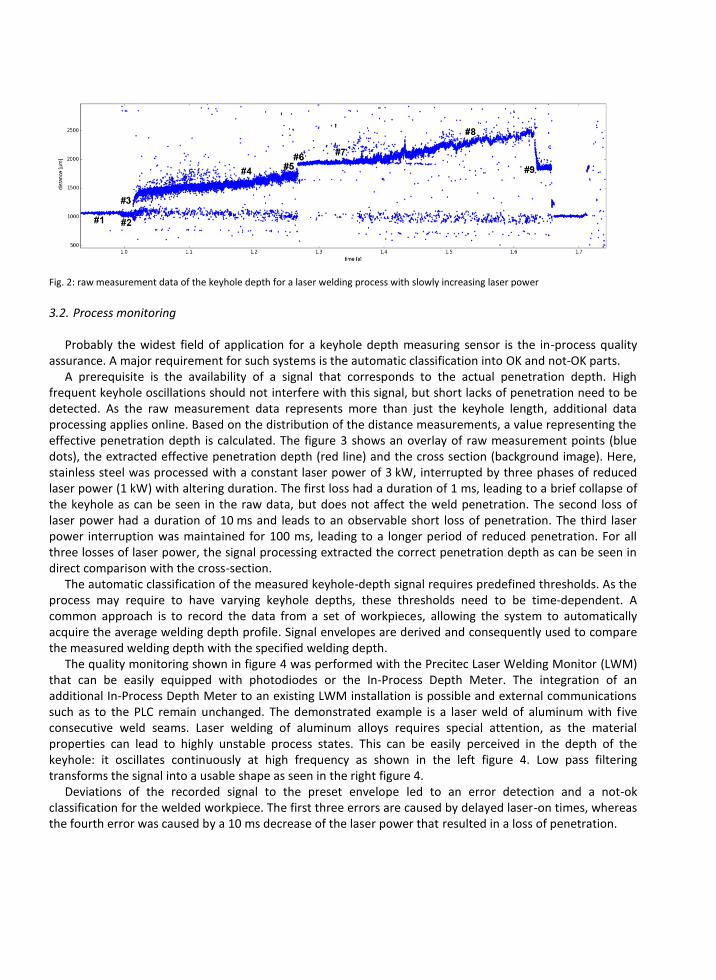
Fig. 2: raw measurement data of the keyhole depth for a laser welding process with slowly increasing laser power
3.2. Process monitoring
Probably the widest field of application for a keyhole depth measuring sensor is the in-process quality assurance. A major requirement for such systems is the automatic classification into OK and not-OK parts.
A prerequisite is the availability of a signal that corresponds to the actual penetration depth. High frequent keyhole oscillations should not interfere with this signal, but short lacks of penetration need to be detected. As the raw measurement data represents more than just the keyhole length, additional data processing applies online. Based on the distribution of the distance measurements, a value representing the effective penetration depth is calculated. The figure 3 shows an overlay of raw measurement points (blue dots), the extracted effective penetration depth (red line) and the cross section (background image). Here, stainless steel was processed with a constant laser power of 3 kW, interrupted by three phases of reduced laser power (1 kW) with altering duration. The first loss had a duration of 1 ms, leading to a brief collapse of the keyhole as can be seen in the raw data, but does not affect the weld penetration. The second loss of laser power had a duration of 10 ms and leads to an observable short loss of penetration. The third laser power interruption was maintained for 100 ms, leading to a longer period of reduced penetration. For all three losses of laser power, the signal processing extracted the correct penetration depth as can be seen in direct comparison with the cross-section.
The automatic classification of the measured keyhole-depth signal requires predefined thresholds. As the process may require to have varying keyhole depths, these thresholds need to be time-dependent. A common approach is to record the data from a set of workpieces, allowing the system to automatically acquire the average welding depth profile. Signal envelopes are derived and consequently used to compare the measured welding depth with the specified welding depth.
The quality monitoring shown in figure 4 was performed with the Precitec Laser Welding Monitor (LWM) that can be easily equipped with photodiodes or the In-Process Depth Meter. The integration of an additional In-Process Depth Meter to an existing LWM installation is possible and external communications such as to the PLC remain unchanged. The demonstrated example is a laser weld of aluminum with five consecutive weld seams. Laser welding of aluminum alloys requires special attention, as the material properties can lead to highly unstable process states. This can be easily perceived in the depth of the keyhole: it oscillates continuously at high frequency as shown in the left figure 4. Low pass filtering transforms the signal into a usable shape as seen in the right figure 4.
Deviations of the recorded signal to the preset envelope led to an error detection and a not-ok classification for the welded workpiece. The first three errors are caused by delayed laser-on times, whereas the fourth error was caused by a 10 ms decrease of the laser power that resulted in a loss of penetration.
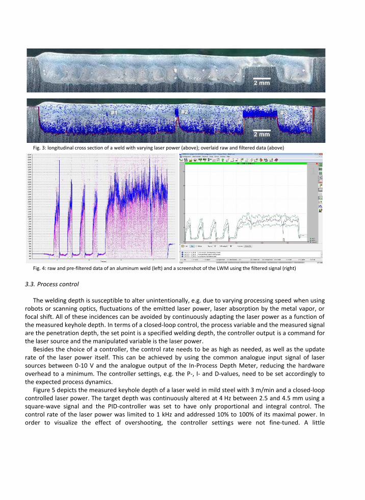
Fig. 3: longitudinal cross section of a weld with varying laser power (above); overlaid raw and filtered data (above)
Fig. 4: raw and pre-filtered data of an aluminum weld (left) and a screenshot of the LWM using the filtered signal (right)
3.3. Process control
The welding depth is susceptible to alter unintentionally, e.g. due to varying processing speed when using robots or scanning optics, fluctuations of the emitted laser power, laser absorption by the metal vapor, or focal shift. All of these incidences can be avoided by continuously adapting the laser power as a function of the measured keyhole depth. In terms of a closed-loop control, the process variable and the measured signal are the penetration depth, the set point is a specified welding depth, the controller output is a command for the laser source and the manipulated variable is the laser power.
Besides the choice of a controller, the control rate needs to be as high as needed, as well as the update rate of the laser power itself. This can be achieved by using the common analogue input signal of laser sources between 0-10 V and the analogue output of the In-Process Depth Meter, reducing the hardware overhead to a minimum. The controller settings, e.g. the P-, I- and D-values, need to be set accordingly to the expected process dynamics.
Figure 5 depicts the measured keyhole depth of a laser weld in mild steel with 3 m/min and a closed-loop controlled laser power. The target depth was continuously altered at 4 Hz between 2.5 and 4.5 mm using a square-wave signal and the PID-controller was set to have only proportional and integral control. The control rate of the laser power was limited to 1 kHz and addressed 10% to 100% of its maximal power. In order to visualize the effect of overshooting, the controller settings were not fine-tuned. A little
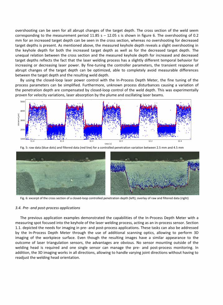
overshooting can be seen for all abrupt changes of the target depth. The cross section of the weld seem corresponding to the measurement period 11.85 s – 12.05 s is shown in figure 6. The overshooting of 0.2 mm for an increased target depth can be seen in the cross section, whereas no overshooting for decreased target depths is present. As mentioned above, the measured keyhole depth reveals a slight overshooting in the keyhole depth for both the increased target depth as well as for the decreased target depth. The unequal relation between the cross section and the measured keyhole depth for increased and decreased target depths reflects the fact that the laser welding process has a slightly different temporal behavior for increasing or decreasing laser power. By fine-tuning the controller parameters, the transient response of abrupt changes of the target depth can be optimized, able to completely avoid measurable differences between the target depth and the resulting weld depth.
By using the closed-loop laser power control with the In-Process Depth Meter, the fine tuning of the process parameters can be simplified. Furthermore, unknown process disturbances causing a variation of the penetration depth are compensated by closed-loop control of the weld depth. This was experimentally proven for velocity variations, laser absorption by the plume and oscillating laser beams.
Fig. 5: raw data (blue dots) and filtered data (red line) for a controlled penetration variation between 2.5 mm and 4.5 mm
Fig. 6: excerpt of the cross section of a closed-loop controlled penetration depth (left); overlay of raw and filtered data (right)
3.4. Pre- and post-process applications
The previous application examples demonstrated the capabilities of the In-Process Depth Meter with a measuring spot focused into the keyhole of the laser welding process, acting as an in-process sensor. Section 1.1. depicted the needs for imaging in pre- and post-process applications. These tasks can also be addressed by the In-Process Depth Meter through the use of additional scanning optics, allowing to perform 3D imaging of the workpiece surface. Even though the resulting images have a similar appearance to the outcome of laser triangulation sensors, the advantages are obvious. No sensor mounting outside of the welding head is required and one single sensor can manage the pre- and post-process monitoring. In addition, the 3D imaging works in all directions, allowing to handle varying joint directions without having to readjust the welding head orientation.
The spatial resolution is hereby given by the scanning speed of the measuring spot and the given sample rate. Spatial resolutions of <25 µm can be achieved in all three dimensions for the region of interest, whereas non-relevant topographies are skipped in the scanning process. Moreover, the coaxial integration of the sensor prevents shadowing effects, allowing high accurate depth measurements of visible pores. As the working range of the sensor can also be very distant to the welding head, pre- and post-process scans can be performed for focusing optics with large stand-off distances. These advantages permit to use the In-Process Depth Meter also for applications where classical laser triangulation sensors would fail.
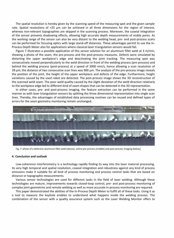
Figure 7 illustrates a possible application of this sensor solution for an aluminum fillet weld at 3 m/min, showing a photo of the seam, the pre-process and the post-process measures. Defects were simulated by distorting the upper workpiece’s edge and deactivating the joint tracking. The measuring spot was consecutively moved perpendicularly to the weld direction in front of the welding process (pre-process) and behind the welding process (post-process) at a speed of 2000 mm/s, hence allowing a scan resolution of 28 µm; the distance of two consecutive scan lines was 900 µm. The analysis of the pre-process image reveals the position of the joint, the height of the upper workpiece and defects of the edge. Furthermore, height variations caused by the used robot are detected. The post-process image shows the 3D reconstruction of the scanned weld seam. The poor weld quality caused by the slight deviation of the weld direction relatively to the workpiece edge led to different kind of seam shapes that can be detected in the 3D representation.
In either cases, pre- and post-process imaging, the feature extraction can be performed in the same manner as with laser triangulation sensors by splitting the three dimensional representation into single scan lines. Thereby, the advantages of established data processing routines can be reused and defined types of errors for the seam geometry monitoring remain unchanged.
Fig. 7: photo of a defective aluminum fillet weld (above), online pre-process (middle) and post-process imaging (below)
4. Conclusion and outlook
Low-coherence interferometry is a technology rapidly finding its way into the laser material processing. Its very high temporal and spatial resolution, coaxial integration and robustness against any kind of process emissions make it suitable for all kind of process monitoring and process control tasks that are based on distance or topographic measurements.
Various sensor technologies are used for different tasks in the field of laser welding. Although these technologies are mature, improvements towards closed-loop control, pre- and post-process monitoring of complex joint geometries and remote welding as well as more accurate in-process monitoring are required.
This paper demonstrated the abilities of the In-Process Depth Meter to fulfill all of these tasks. Using it as a tool to measure the keyhole enables to understand what happens inside the welding process. The combination of the sensor with a quality assurance system such as the Laser Welding Monitor offers to
autonomously detect weld defects that remain unseen by conventional sensors. By feeding the laser source with a power signal, the sensor offers closed-loop control of the penetration depth. The fourth shown application example demonstrated the ability to compete with current pre- and post-process sensors.
Upcoming developments might include the 3D modelling of the keyhole’s geometry, all-in-one sensors for simultaneous pre-, in- and post-monitoring and self-tuning welding robots. Also other laser applications, such as the selective laser melting, will benefit from the advantages of the low-coherence interferometry.
References
Weberpals, J.-P., Böhm, D., Müller, S., 2015. Laser beam remote welding of aluminum hang-on parts, European Automotive Laser
Applications 2015, Bad Nauheim, Germany.
Dorsch, F., 2015. New approaches in process monitoring and seam tracking increase robustness and reliability of laser welding processes, European Automotive Laser Applications 2015, Bad Nauheim, Germany.
Vogl, W., Munzert, U., Megerle, U., 2014. Robotic 3D scanner welding with on-the-fly seam tracking, European Automotive Laser
Applications 2014, Bad Nauheim, Germany. Eriksson, I., Norman, P., Kaplan, A., 2009. Basic study of photodiode signals from laser welding emissions. Proceedings of 12th Nordic
Laser Materials Processing Conference (NOLAMP), Copenhagen, Denmark.
Weberpals, J.-P., et al., 2011. Utilisation of thermal radiation for process monitoring, Proceedings of Lasers in Manufacturing 2011, Munich, Germany.
Bardin, F., at al., 2005. Closed-loop power and focus control of laser welding for full-penetration monitoring, Optical Society of America,
Applied Optics, Vol. 44, No. 1, p. 13-21. Blug, A., et al., 2011. Closed-loop control of laser power using the full penetration hole image feature in aluminum welding processes,
Proceedings of Lasers in Manufacturing, 2011, Munich, Germany. Stork genannt Wersborg, I., et al., 2009. Multiple sensors and artificial neural networks in a cognitive technical system for laser welding,
Proceedings of International Conference on Intelligent Sensors, Sensor Networks and Information Processing (ISSNIP), p. 109-114.
Abt, F., et al, 2011. Novel X-ray system for in-situ diagnostics of laser based processes - first experimental results, Proceedings of Lasers in Manufacturing, 2011, Munich, Germany.
Huang, W., Kovacevic, R., 2009. Feasibility study of using acoustic signals for online monitoring of the depth of the weld in the laser
welding of high-strength steels, Proc. of the Institution of Mechanical Engineers, Part B: J. of Eng. Man., Vol. 223, p. 343-361. Konuk, A., et al., 2011. Closed loop control of laser welding using an optical spectroscopic sensor for Nd:YAG and CO2 lasers,
Proceedings of ICALEO 2011, Laser Institute of America, Orlando, USA.
Shao, J., Yan, Y., 2005. Review of techniques for on-line monitoring and inspection of laser welding, Journal of Physics: Conference Series 15, p. 101-107.
Norman, P., Engström, H., Kaplan, A., 2007. State-of-the-art of monitoring and imaging laser welding defects, Proceedings of 11th
Nordic Laser Material Processing Conference (NOLAMP), Lappeenranta, Finland. Purtonen, T., Kalliosaari, A., Salminen, A., 2014. Monitoring and adaptive control of laser processes, Proceedings of 8th International
Conference on Photonic Technologies LANE 2014, Fürth, Germany.
Bautze, T., Zösch, A., 2011. Laserschweißen mit höchster Qualität bei reduzierter Leistung, Laser Technik Journal 11/2011, p. 29-33. Schürmann, B., Kogel-Hollacher, M., 2008. Bearbeitungsoptik zum Remote-Schweißen mit integrierter Sensorik, Projekt RoFaLas,
Münchener Kolloquium, Munich, Germany.
Schneider, F., Kogel-Hollacher, M., 2015. Laserschneiden von TP-FVK mit cw- und Kurzpulslasern - Prozessführung und Anlagentechnik, Abschlussveranstaltung des BMBF-Projektes InProLight, Aachen, Germany.
Neef, A., et al., 2014. Low coherence interferometry in selective laser melting, Proceedings of 8th International Conference on Photonic
Technologies LANE 2014, Fürth, Germany. Schmitt, R., et al., 2012. Inline process metrology system for the control of laser surface structuring processes, Proceedings of 8th
International Conference on Photonic Technologies LANE 2014, Fürth, Germany.
Webster, P., et al., 2010. In situ 24 kHz coherent imaging of morphology change in laser percussion drilling, Optics Letter, Vol. 35, No. 5, p.646-648.
Kogel-Hollacher, M., Schönleber, M., Bautze, T., 2014. Inline coherent imaging of laser processing - a new sensor approach heading for
industrial application, Proceedings of 8th International Conference on Photonic Technologies LANE 2014, Fürth, Germany. Bautze, T., Kogel-Hollacher, M., 2014. Keyhole depth is just a distance, Laser Technik Journal 4/2014, p. 39-43.
Lohaus, L., Bautze, T., Diepold, K., 2010. Evaluation of optical sensors for laser welding in a technical cognitive environment,
Proceedings of ICALEO 2010, Laser Institute of America, Orlando, USA. Kogel-Hollacher, M., 2014. Finalist des Innovation Award Laser Technolog 2014 - Messung der Einschweißtiefe und der Topographie in
der Laser-Materialbearbeitung mit Hilfe der Kurzkohärenz-Interferometrie, Laser 2-2014, p. 22-23.
Boley, M., Weber, R., Graf, T., 2015. Online detection of pore formation during laser deep-penetration welding, Proceedings of Lasers in Manufacturing, 2015, Munich, Germany.


![PECULIARITIES OF LASER WELDING OF METALS · PECULIARITIES OF LASER WELDING OF METALS ... technological process and also broadened application of this method [1,4]. The laser welding](https://img.pdfslide.us/doc/110x75/5e0d62e12e988379d40e28d6/peculiarities-of-laser-welding-of-peculiarities-of-laser-welding-of-metals-technological.jpg)