Embed Size (px)
Citation preview

USE OF HYDRATES TO
STORE NATURAL GAS
Ben Aseme
Adebusola Odunuga
05/08/2009
1

Abstract
Storage of Natural gas is needed and important in the oil and gas industry. There
are existing methods of storing natural gas but the use of hydrates is one of increasing
interest. Natural gas hydrates can be useful since some naturally occur in polar and
deep oceanic regions. In this project, focus is placed on storing natural gas using
hydrates formed using pressurized tanks. Natural gas hydrates were found to have
lower capital cost than other methods used for storing natural gas currently in the
industry as a result of absence in need for cushion gas. Cushion gas accounts for a
sizeable amount of the fixed capital investment especially in other forms of natural gas
storage systems. Salt caverns were shown to be profitable for short term storage but also
showed relatively high activation costs.
Storing natural gas using hydrates is definitely an option that should be
investigated given the resource value of natural gas.
2

Executive Summary
Gas Hydrates are practically clathrates of natural gas in which water solidify to
form a crystal system. In this project, other methods used in storing natural gas were
analyzed and compared to storing natural gas using hydrates. Hydrates can be
naturally found in deep polar region where there is high pressure and low
temperatures. The storage method using hydrates is observed through a pressurized
tank. Total cost of natural storage using hydrates for capacity of 107 mmbtu is
$2.46/mmbtu. For the same capacity, the total capital investment is $15.00/mmbtu and
the return on investment is 0.65 which increases as the capacity of the storage tank
increases. Natural gas hydrates have lower total capital investment than the other three
methods of storage studied (Depleted Reservoir, Aquifer, and salt caverns). Hydrates of
natural gas can be very useful for peak shaving. Suppliers can make tank readily
accessible to consumers when needed, which will reduce the strain on resources when
natural gas in high demand.
3

Table of Contents
Introduction...........................................................................................................................................5
Natural gas storage..................................................................................................................................6
Business Plan............................................................................................................................................6
Natural gas Hydrates..............................................................................................................................9
Storage methods of Hydrates.............................................................................................................11
Depleted Gas Reservoirs...........................................................................................................................14
Injection/Withdrawal wells................................................................................................................15
Compressor........................................................................................................................................17
Gathering systems(Piping).................................................................................................................20
Valves................................................................................................................................................21
Pumps................................................................................................................................................22
Gas flow meters.................................................................................................................................23
Dehydrators.......................................................................................................................................24
Central point separators....................................................................................................................26
Cushion gas............................................................................................................................................27
Labor..........................................................................................................................................................30
Installation ................................................................................................................................................31
Insurance...................................................................................................................................................32
Salt Caverns...............................................................................................................................................32
Aquifer......................................................................................................................................................35
Economic Analysis.....................................................................................................................................36
Conclusion.................................................................................................................................................40
Work Cited................................................................................................................................................41
Appendix...................................................................................................................................................43
4

Introduction
The fossil fuel natural gas is a mixture of the hydrocarbon gases methane (70-
90%), ethane, propane, butane (0-20%), carbon dioxide (0-8%), oxygen (0-0.2%), nitrogen
(0-5%), hydrogen sulfide (0-5%) and rare gases (trace). Natural gas is a resource
primarily because it releases substantial energy when combusted or burned (approx.
1000 Btu/cubic ft). Natural gas is composed primarily of methane and its combustion
equation is given below as:
CH4[g] + 2 O2[g] -> CO2[g] + 2 H2O[l] + Energy [kJ] Equation 1
Compared to all other fossil fuels, natural gas combustion produces less
environmentally-harmful materials per volume of energy released making it the
cleanest burning fossil fuel. The released energy is used residentially, commercially and
industrially for heating or power generation purposes. Natural gas currently satisfies
24% of total energy consumption in the United States with a projected annual growth of
1% over the next 20 years. These important characteristics of natural gas make it a
valuable energy resource now and for the future.
5

Natural Gas Storage
Traditionally, the demand for natural gas has been highly seasonal. In colder
climates, the winter months demand more natural gas supplies for heating purposes
while warmer climates might demand more natural gas supplies during the hot
summer months for air cooling requirements. These periods of seasonal high demand
are referred to as base periods. Periods of daily or weekly high demand are referred to
as peak periods and can vary as much +/- 20% from the average consumption rates. The
resource value, unsteady pattern of natural gas demand and the fact that most primary
gas producers and primary gas consumers are not in proximity warrant storage
system(s) that will guarantee consumers natural gas supply by reserving excess natural
gas during the low demand periods for supply during the high demand periods.
Business Plan
An analysis is conducted to compare 3 existing methods of storing natural gas.
They are listed below together with our proposed method.
Depleted gas reservoirs
Salt caverns
Aquifers
Natural gas hydrates (Proposed)
6

In each of the main storage methods, natural gas is stored in large reservoirs
underground. Natural gas is injected into the underground reservoir or formation at
pressures exceeding the natural pressure of the gas. Gas is extracted for delivery using
the reservoir-to-wellhead gas pressure differential through standard gas wells. To attain
and maintain this pressure differential, the reservoir pressure must be above the gas
wellhead pressure. Hence a certain amount of gas (base or cushion gas) must remain in
the reservoir to provide the needed pressure differential. The gas withdrawn during
delivery cycles is called the working gas. It can then be deduced that withdrawal rates
are highest when the withdrawal cycle begins and decrease as the working gas amount
reduces.
A comprehensive study of the cost factors associated with each storage method is
needed so as to make appropriate comparisons between our proposed method and the
known methods of natural gas storage. Listed below are cost factor components of
typical gas storage facilities:
Injection wells/Withdrawal wells
Compressors
Gathering system
Valves
7

Pumps
Gas flow meters
Dehydrators
Separators
Cushion gas
Power (Electricity)
Land
Labor
Equipment Installation/Setup
Property Taxes/Insurance
Most of these cost factors apply to all storage methods although minimal changes
might apply depending on the storage method. These factors will be developed and
explained for the depleted gas reservoir gas storage method and applied to the other
storage methods. Necessary cost factor changes will be made wherever they may apply.
8

Natural Gas Hydrates
Gas hydrates are naturally occurring solids composed of water molecules
forming a rigid lattice of cage with most of the cages each containing a molecule of
natural gas. Gas hydrates naturally occur both at very low temperatures and high
pressure regimes in Deep Ocean.
Hydrates form in three repeating crystal structures; Structure I, Structure II, and
Structure H. Structure I, is a body-centered cubic structure form with small natural gas
molecules found in Deep Ocean. Structure II is a diamond lattice within a cubic
framework, forms when natural gases or oils contain molecules which commonly occur
in production and processing conditions. The newest form of hydrates just Structure H
is an hexagonal structure that has cavities that have large enough to contain molecules
size of common components of naphtha and gasoline.
FFig 1. Structure of Gas Hydrates (Henriet &Mienert 1998)
9

The geometry of structure is represented by the kind of cages they have. Crystal
structures depend on the kind of lattice which contains natural gas. In this case,
methane is the only natural gas to be considered. Table 1 shows the breakdown of each
crystal structure according to their type.
Table 1: Hydrate Crystal Structure (Henriet &Mienert, 1998)
512 represent a crystal structure that has 12 faces with five sides per face. Methane gas
forms Structure I crystal structure in which calculations are based on. The temperature
and pressure at which hydrates can exist must fall under certain limits. Fig 2 shows the
boundaries at which they must occur. In this project, Pressure at 6MPA and
temperature of 20 0C were chosen since it falls within boundary needed for stable
hydrate.
Fig 2: Boundaries of Temperature and Pressure
10

Storage Method of Hydrates
There are several advantages associated with storing natural gas using hydrates.
Hydrates can be used for economic storage of natural gas in cold countries and the cost
associated can be relatively minimized. The use of natural gas hydrates for storage is
also an alternative that maintains a high degree of safety. When a large volume of
natural gas is ignited, explosions occur but with natural gas, the effect is drastically
reduced due to water molecules present.
There are two ways of evaluating the cost of using hydrates. Fig 3 shows two options.
Fig 3: Possible options for evaluating gas hydrates
11

Drilling to conditions where the formation of hydrates is favorable can be
expensive and time consuming. Also the geological formation of such topography must
be monitored to ensure that natural gas can be stored with escape. Another method is to
create a pressurized tank that would simulate the same conditions (Low temperature
and High pressure). This method would enable engineers monitor the amount of gas
stored and would create easy accessibility when needed. An Hydrate tank can also be
created by using a refrigeration system, therefore keeping hydrate at temperature
needed and also maintaining an average pressure. Below is the PFD for hydrates design
Pressurized Tank
Gas Supply
Pump
Storage for water/gas mixture
Gas and water slurry supply after storage
Gas and water mixture
Flare gas
water
Fresh water supply
Recycle water
Fresh water supply
Compressor 129KW
Gas supply
V-2 V-3
V-4
Fresh water supply
V-5
V-6
Pressurized vessel heated
Heat
V-13
Fig 4: PFD of storage systems using Hydrates
12

The cost of this storage method was based on the amount of natural gas to be stored
and the size of each hydrate. The rate of hydrate formation must be evaluated. This was
done using the equation below (Mannel, 2008)
Where R is the rate of hydrate formation, μ2 is the second moment of distribution
around particle size for hydrate; f is the fugacity of gas, feq is the fugacity of gas at
equilibrium, and K* is the kinetic parameter. The chosen parameter for pressure and
temperature is 6MPA and 273k. Using this parameters and the CNGA equation of state,
compressibility is calculated
Where z is the compressibility, SG is specific gravity of gas, P is pressure in psig, and T
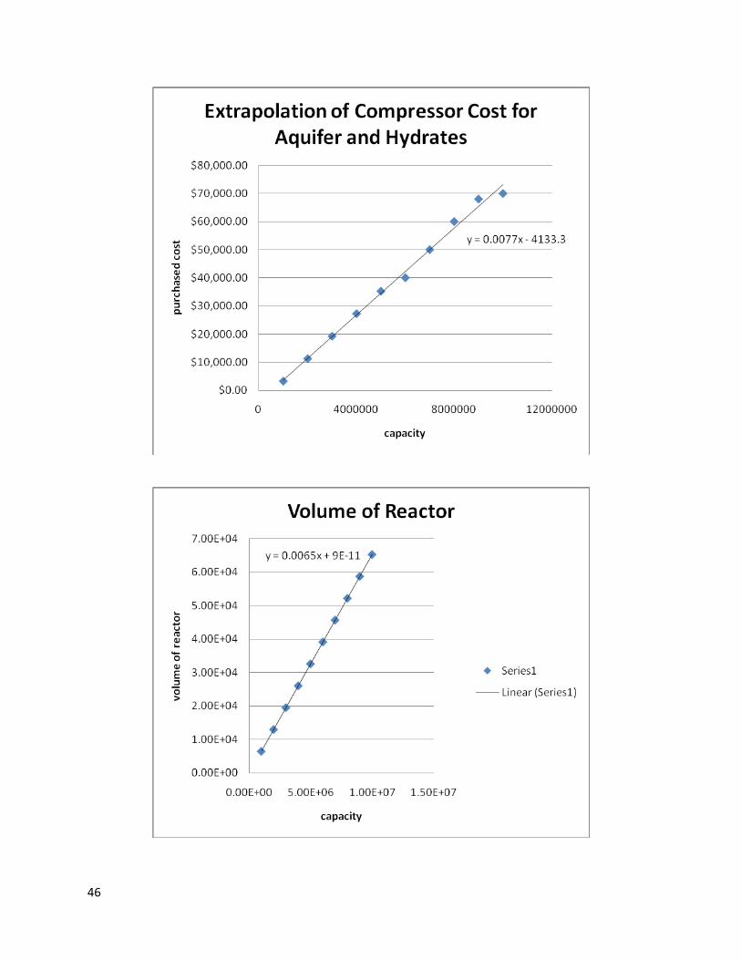
is temperature in ˚R. In estimating the volume of the reactor, the equation below is
used,
Where V is the volume of the reactor, Q is the gas flow rate in the reactor, R is the rate of
hydrate formation. When the capacity of the reactor tank is achieved, the cost can be
estimated using (Timmerhaus, 5th Edition). This estimation is based on the cost of tank
13

with insulation and a stirrer. Other cost associated with using hydrates for natural gas
includes equipment cost, cost of installation, and fees associated with storage.
For re-gasification, the tank is depressurized and heat is applied to the tank. Below is a
PFD diagram illustrating the design.
Storage for water and gas mixture
Slurry mixture
Gas
Heat
V-14
Gas and water slurry after depressurizing
Recycled water flowing back to the system
Water removed
Fig 5: PFD showing gas recovery method
Depleted gas reservoirs
Depleted gas reservoirs are natural gas reservoirs that have been sapped of all
recoverable natural gas. This results in an underground geological formation that is
capable of holding or reserving natural gas. Storing natural gas using depleted
14

reservoirs is the most common gas storage method. This partly due to the fact that most
of the infrastructure already exist thereby minimizing activation costs and time.
Injection/Withdrawal wells
Gas wells are used to transfer gas into and out of a gas storage reservoir.
Combination injection/withdrawal wells are most common because of their reduced
cost but this depends on the reservoir characteristics (H2O influx, gas bubble shape, etc).
These wells are usually much larger in diameter than normal gas producing wells to
allow increased gas deliverability. For this study, we assumed worst case scenario and
chose to use separate gas injection and withdrawal wells. We opted to use schedule 40
medium grade steel with nominal diameter of 0.5 inches as our well casing and tubing
material. The well casing had an inner diameter of 12.625 inches and outer diameter of
15 inches while the well tubing had an inner diameter of 12 inches and an outer
diameter of 0.624 inches. The well casing material weighed approximately 9.3 lbs per
foot length and the well tubing material weighed approximately 2.4 lbs per foot length.
The average depth of natural gas reservoirs is 5500 feet which gives a total of 51,150 lbs
and 13,200 lbs of medium grade steel for the well casing and tubing respectively.
Current prices for medium grade steel are about 1,000 dollars per lb. The resulting total
15

cost for well casing material is 153 million dollars and 39 million dollars for well tubing
material.
Depleted gas reservoirs have the largest holding capacity of all gas storage
methods therefore requiring a slightly higher number of injection and/or withdrawal
wells. A minimum of 2 injection wells and 1 withdrawal well would suffice bringing the
total well material cost to 193 million dollars. The calculated cost is for replacing the
well materials after years of disuse for a reservoir with this maximum capacity.
16

Fig 6: Diagram showing an observation, withdrawal and injection well (http://www.princeton.edu/~hotinski/Resources, 2006)
Compressors
17
Compressors increase the flow rate of a fluid by decreasing its volume.
Compressors are needed to provide the needed injection horsepower to fill the gas
reservoir. Compressor discharge pressures vary greatly between the beginning and end
of the injection process. Centrifugal compressors are not designed to sustain such
varying ranges thus reciprocating – type compressors were used in this case.
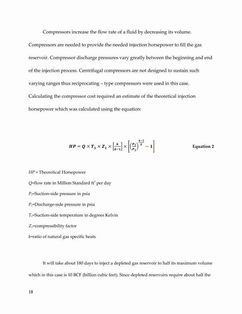
Calculating the compressor cost required an estimate of the theoretical injection
horsepower which was calculated using the equation:
Equation 2
HP = Theoretical Horsepower
Q=flow rate in Million Standard ft3 per day
P1=Suction-side pressure in psia
P2=Discharge-side pressure in psia
T1=Suction-side temperature in degrees Kelvin
Z1=compressibility factor
k=ratio of natural gas specific heats
It will take about 180 days to inject a depleted gas reservoir to half its maximum volume
which in this case is 10 BCF (billion cubic feet). Since depleted reservoirs require about half the
18

maximum storage volume to be used as cushion gas, the gas injection flow rate (Q) is
approximately 28 million standard cubic feet per day. The compressor is operating under
standard conditions therefore the suction-side gas temperature (T1) and pressure (P1) are 288
Kelvin (15 0C) and 14.7 psia (1 atm) respectively. The discharge-side pressure (P2) is equivalent
to the maximum reservoir pressure which is approximately 550 psia (37.4 atm) for a total gas
volume of 10 BCF. The compressibility factor (Z1) for natural gas is given by the equation:
Equation 3
Vm = molar volume
R = gas constant
The molar volume used in this calculation was 22.5 (liters/mole) and the gas
constant was 0.082 (liters*atm/Kelvin*mol). Substituting values into equation 3 gives a
compressibility factor of 0.95. The ratio of specific heats (k) is given by the equation:
Equation 4
Cp = Gas specific heat capacity at constant pressure
Cv = Gas specific heat capacity at constant volume
The specific heat capacity of natural gas at constant pressure is 0.56 Btu/lbmoF and
0.44 Btu/lbmoF at constant volume. The ratio of specific heats (k) has a calculated value of
19

1.27. From equation 2, the compressor requires about 41,500 horsepower theoretically. It
has been noticed that compressors lose ideal functionality after weeks of operation
because gas properties may vary from the compressor design basis. It is therefore
advisable to multiply the theoretical horsepower by a de-rating factor when sizing the
compressor. A de-rating value of 0.95 is reasonable in obtaining the actual compressor
horsepower. Our compressor thus requires about 39,400 horsepower actually. The
calculated compressor cost is about 39,000,000 dollars. This depleted gas reservoir needs
two compressors for the two injection wells which gives a total compressor cost of 79
million dollars for maximum capacity.
20

Fig 7: Reciprocating compressor (http://images.google.com, 2008)
Gathering system
The gathering system is a network of pipes that connect the gas reservoir wells to
central gas collection points. These ½ inch nominal diameter, schedule 40, medium
grade carbon steel pipes have larger diameters than those of producing gas field wells
to accommodate the increased volumes from the large-bore gas reservoir wells. The
thickness and internal diameter of this gathering system’s pipe were 1 and 15 inches
respectively. Pipe lengths of approximately 400 meters (1312 feet) are reasonable and
21

were used in this case. The calculated weight for this pipe material is 10 lbs/ft which
gives a total pipe weight of 13,000 lbs. At an average cost of 1,000 dollars per lb, it
would cost approximately 13 million dollars maximum to setup our gas gathering
system.
Fig 8: Gas gathering system (www.ogfj.com/Articles/Article_Display.cfm?Art, 2005)
Valves
Valves control fluid flow by fully or partially closing or opening. Valves are
important in controlling the flow pattern of gas into and out of the gas storage reservoir.
Stainless steel self-contained control valves (½ inch nominal diameter) that can
withstand the maximum reservoir pressure of 550 psia were used in this case. The
calculated cost for purchasing our valves came up to 13 million dollars. This cost varied
22

with the capacity of the reservoir and the corresponding nominal diameter (which
depended on the gathering system pipe size) using java programming techniques.
Fig 9: Sample self-controlled gas valve (http://www.globalspec.com, 2000)
Pumps
Pumps are used to transfer fluids between locations. Associated pump costs
were calculated using the gas withdrawal capacities of the pumps. The working gas
withdrawal rate for the average depleted reservoir is 120 days. Dividing half the total
gas volume (5 BCF) by the withdrawal period gives a gas flow rate of 41.7 million
standard cubic feet per day. This is equivalent to 13.7 cubic meters (3615 gallons) per
second. The calculated cost of a withdrawal well pump with this capacity is
approximately 420, 000 dollars.
23

Fig 10: Vertical reciprocating pump (http://images.google.com, 2008)
Gas flow meters
These are devices used to maintain accurate gas injection and withdrawal
inventory control by measuring the flow or quantity of the moving gas. Gas flow meters
are an important component in a natural gas storage facility because inaccurate gas flow
measuring techniques could imply significant financial losses. After extensive research,
we opted to use the GE panametric ultrasonic GM868 ultrasonic gas flow meter for our
storage facilities. The versatility, accuracy and space saving design of this gas flow
meter make practical sense. This flow meter costs about 5,000 dollars. This price does
not vary with the capacity of the reservoir because it comes in a one-size-fits-all model.
24

Fig 11: GE panametric ultrasonic GM868 ultrasonic gas flow meter (http://cgi.ebay.com, 2009)
Dehydrators
Most storage facilities possess a certain amount of water within their geological
formations. This residual liquid evaporates into the injected gas and upon withdrawal,
can decrease the pipeline quality of the gas and cause pipeline freezing if the gas is not
dehydrated. These dehydrators are located at the central collection point and basic
glycol units. Glycol units are used because of their cost-cutting potential and
satisfactory performance. A glycol unit works by pulling the ‘wet’ natural gas through
the bottom of an absorber containing glycol. As the ‘wet’ gas penetrates upward, it
25

releases its water into the glycol solution and dry gas is obtained at the top of the
absorber. When saturated with water, the glycol solution is pumped through a reboiler
or regenerator which boils the glycol-water mixture and separates the glycol from the
water. After separation, the glycol can be returned to the absorber to contact and
dehydrate additional wet gas. The associated cost was about 12,500 dollars and it was
also constant for varying reservoir capacities.
Figure12: Glycol dehydration process (www.images.google.com, 2009)
26

Central point separators
Central point separators are used for both the injection and withdrawal gas
streams in a gas storage facility. Injection gas separators prevent injection pipeline dirt
and debris from contaminating and clogging compressors and the well bore. The
withdrawal separators prevent reservoir sand and water particles from entering the
pumps and delivery pipeline. These separators should be designed to handle gases and
liquids because of the high probability withdrawn gas is going to contain water
molecules. Our separator cost about 1,700 dollars and varied with capacity due to glycol
replacement costs.
Figure 13: Gas/liquid separators (http://www.peerlessmfg.com/pdf, 2008)
27

Cushion gas
The cushion gas requirement for depleted gas reservoir storage systems is half
the total storage capacity. We have a maximum storage volume of 10 BCF for this
depleted gas reservoir. Current well-head prices for natural gas average $4.00/mmbtu.
We are using this as our standard price for purchasing the stored gas but will vary this
cost to see how our storage cost plots respond. The calculated cushion gas would total 5
million mmbtu at a purchase cost of 20 million dollars. This is just the cost of
purchasing the gas to be stored. It costs $0.40/mmbtu to store the gas for depleted
reservoirs. It would therefore cost 2 million dollars to store the gas in this reservoir. Gas
injection and withdrawal fees also apply costing about $0.02/mmbtu for both cycles. It
would therefore cost $100,000 to inject the working gas into the reservoir. The same cost
would apply during the withdrawal cycle. Cushion gas costs total 22.1 million dollars
for a storage reservoir of this maximum capacity at $4.42/mmbtu. This cost varied
slightly with increased and decreased gas purchase costs of $2.42/mmbtu, $6.42/mmbtu,
and $8.42/mmbtu.
Power (Electricity)
Electricity costs for the operation of this gas reservoir are based on the
compressor and pump power requirements. Calculating the power rating of the pump
28

requires that we calculate the hydraulic and shaft power of the pump. The hydraulic
power of the pump is calculated using the equation:
Equation 5
Ph=Hydraulic power (Kilowatts)
H=Total head (Suction pressure – Discharge pressure)
Q=Fluid flow rate (m3/s)
ρ= density of the fluid (kg/m3)
g=acceleration due to gravity (m/s2)
We have a total head of 5485.3 psia, density of 0.8 kg/m3, fluid flow rate of
13.7m3/s and g to be equal to 9.8 m/s2. From equation 5, the total hydraulic power
requirements for the pump equal 589 kilowatts. The shaft power is derived from the
equation:
Equation 6
29

The term η is the efficiency of the pump which for reciprocating pumps is
approximately 70%. The calculated shaft power is thus approximately 841 kilowatts.
The electrical power input is calculated by dividing the shaft power by an efficiency
factor of 0.5. This results in a total electrical power requirement of 1682 kilowatts per
hour for the pump. At current costs of $0.05/kilowatt-hr for electricity, the pump would
incur electricity costs of 84 dollars per hour. Withdrawal cycles are typically in the
range of 120 days. The pump would be operating for a total 2880 hours bringing the
total electricity costs to 23, 000 dollars for the pump. The compressors operate at 39,705
horsepower which is equivalent to 3221.4 horsepower-hours (4,320 kilowatt-hours). At
the cost of $0.05/kilowatt-hr, the total cost of operating the compressors for the 180-day
injection period totals 6 million dollars. The total electricity costs for a depleted
reservoir with our maximum capacity is approximately 6.4 million dollars for the
combined injection and withdrawal periods.
Land
There are restrictions when dealing with land used for natural gas storage. Wells
or tanks containing large volumes of natural gas must be wells spaced at least 320-640
acres apart to allow efficient reservoir damage and to maximize the recovery of natural
gas. No storage method must be located within 100 feet from private homes, 150 feet
from public buildings and 50 feet from any stream. These criteria were used in
30

evaluating the cost of leasing or purchasing land that could be used for natural gas
storage. For depleted reservoir calculations we used an approximate value of 10,000
acres at a yearly leasing cost of $25 per acre. This gave a yearly leasing cost of $250,000
dollars for maximum capacity operation.
Labor
Labor costs are important cost factor of gas storage facilities. Labor costs for gas
storage facilities are incurred during the activation or design implementation period
and possibly the gas withdrawal period also. For depleted gas reservoirs, this activation
period is approximately 4 weeks because most of the needed infrastructure is already in
place. Labor costs for activation projects are in the range of 30 dollars/hr per worker.
This would result in a total labor cost of approximately 20, 000 dollars per worker over
a four-week period. This cost also includes relocation, housing, feeding and
transportation for each worker. Assuming it takes a ten-man team to activate a depleted
reservoir, labor costs would total 200, 000 dollars for the four-week activation period.
The withdrawal cycle would also require manpower to run the pump and other
machinery so we assume it would cost 22 dollars/hr for each worker. Three workers
would provide enough manpower for the entire 120 day withdrawal period. This gives
combined labor costs averaging 190,000 dollars. This cost did indeed vary with storage
capacity as less man-hours are needed as storage capacity reduces.
31

Fig 14: Fieldman hard at work (http://images.google.com, 2008)
Equipment Installation/Setup
The equipment installation costs as a percentage of the equipment cost are as
follows:
Separators: 40%
Compressors: 45%
Dehydrators: 42.5%
Flow meters: 30%
Pumps: 43%
Valves: 40%
Piping: 38%
32

This gave us a total installation cost of about 40 million dollars for a 10BCF
maximum capacity storage reservoir.
Property Taxes/Insurance
Property taxes are in the range of 2 to 4 percent for highly populated areas and in
the range of 1 to 2 percent for less populated areas. Gas reservoirs are primarily situated
in remote, less populated areas. Property taxes for our depleted gas reservoir are about
1.5 percent of the total fixed capital investment. Property insurance is about 1 percent
the total fixed capital investment per year. Totaled costs came to 3.5 million dollars and
decreased for lesser storage volumes. Details of our results are contained in the attached
excel sheets.
Salt Caverns
Salt caverns for the storage of natural gas are large underground tanks created
form salt deposits (salt domes or beds) by solution mining (leaching) procedures. The
salt is dissolved by injecting water through the well tubing. The dissolved salt is
pumped out through the well casing. The resulting brine is sold to salt companies or
injected into porous rock formations far beneath any surrounding water reservoirs. The
cavern dimensions can then be determined directly by the water injection flow rate and
the bottom-end position of the well tubing. Sound technology is used to determine if
the proper cavern dimensions have been reached through leaching and the resulting
33

cavern space is dried using gas injection. Although salt caverns are generally much
smaller in capacity than any other storage method, their walls can possess structural
integrity as high as that of steel preventing little or no gas seepage. This makes salt
caverns very ideal for gas peak shaving. We are assuming this salt cavern has a
maximum gas holding capacity that is half that of that of the depleted reservoir. Our
calculated costs for a salt cavern included all the cost parameters previously explained.
The costs comparisons between depleted reservoirs and salt caverns are shown are
shown in the plots below and explained in detail in our attached excel sheets.
Fig 15: Cost comparison for depleted reservoir and salt cavern.
34

Our results show negligible changes on the overall curve for both depleted reservoirs
and salt caverns when the purchase cost of gas was varied. A plot of the return on
investment is shown below with the average gas purchase cost of $4.42/mmbtu.
Fig 16: Return on investment plot for a depleted reservoir and salt cavern
Our plots show error bars which were calculated with 30 percent error. This was
derived by calculating the error values for each cost component and finding the error
average.
35

Overall our plots show that salt caverns are more profitable at smaller storage volumes
but depleted reservoirs are more profitable long term.
Aquifer
Aquifers are underground porous, permeable rock formations that act as natural water
reservoirs. However, in certain situations, these water containing formations may be
reconditioned and used as natural gas storage facilitiesi. In order to consider aquifer for
natural gas storage, several factors have to be considered. The Geological characteristics
of an aquifer are important.
Fig 17: Aquifer cushion gas needs vs. Depleted reservoir gas needs
If an aquifer is found appropriate for storage, other supporting infrastructure has to be
built to support its use. Aquifers require cushion gas of up to 80% of total volume
which make its utilization very high. Aquifers are mostly built when the price of natural
36
Working gas (50%)
Base or Cushion gas
(50%)
Working Gas- (20%)
Base or Cushion Gas
(80%)
Capacity of storage field

gas is low. This is done to minimize the cost of natural gas spent as cushion gas. To
determine the cost of developing an aquifer, similar criteria used for depleted reservoir
was used. Since aquifers are natural water reservoirs, water must be evacuated before it
can be used as natural gas storage. One of the major environmental concerns is the case
of leaky aquifer. Enough amount of cushion gas must be in place to prevent any
leakage. Pressure is an important parameter. Aquifers must operate at a high pressure
to reduce the possibility of leakages. Cost analysis include labor, compressor, pump,
utilities, land, cushion gas other miscellaneous cost. Below shows the PFD diagram for
Aquifer design
P-19
E-9
compressor
Gas supply
V-2 V-3
V-1
Aquifer Underground Storage
Withdrawal pipe
Injection of gas
Withdrawal pipe
V-12
Fig 18: Aquifer system Design
Economics and Risk Analysis
The graph below shows the cost of storage per mmbtu. According to our results,
Aquifer cost higher than hydrate after designed. This is due to the volume of cushion
37

gas needed before natural gas can be stored. Using hydrates to store natural gas seems
to be more stable and less expensive when a pressurized tank is used.
Fig. 19: Graph comparing storage method
The total cost of hydrates for 106 mmbtu is $25 million while aquifer cost approximately
$60million. If the cost of natural gas reduces to about $2/mmbtu, then it would cost
approximately the same amount to build an aquifer storage or create a storage tank for
hydrates. In todays market, it is unlikely that natural gas would become that cheap.
Current market price for natural gas is about $4/mmbtu. Using that price, then it would
cost about $40million more to get an Aquifer ready for natural gas storage.
38

Fig 20: ROI comparison for Hydrates and acquifers at different gas prices
The return of investment on hydrates would determine whether this proposed
method is profitable. Hydrates has a higher rate of investment even when the cost of
natural gas is cheap. At 107mmbtu, the return on investment is about 0.65%. It then
progressively increasing until it levels off. This is about 40% greater than Aquifer.
Since the price of natural gas fluctuates depending on the season, the cost of cushion
gas is varied. This gives an increase in total cost for each storage method. The graph
below shows the comparison for aquifers.
39

Fig 21: Effects of change in natural gas prices on aquifer costs
Summary Results for Aquifers and Hydrates
Hydrates Aquifers
Compressor $291,466.80
Pumps $83,333.34
Cushion Gas - $32,000,000.00
Extra Fees $1,800,000.00
Land $45,000.00 $25,000,000.00
Utilities $42,000.00
Pressurised Tank $24,625,109.00 -
Valves $182,625.97
Pipes $181,779.20
TCI/mmbtu $15.18 $35.65
ROI $0.66 $0.28
40

Total Cost $25,591,314.31 $60,113,205.31Table 2: Cost summary for hydrates and aquifers
Conclusion
Natural gas hydrates can be very useful for storing natural gas. Studies shows that it
can be profitable when managed and designed to save money. Natural gas hydrates
could provide easy access to storage when needed. Increased capacity makes the cost
economically feasible and return on investment would increase over time. Operating
cost of gas hydrates is low compared to the other methods; therefore more research
should be carried out on the use of gas hydrates as natural gas. Exploring the possibility
of storing gas using hydrates is definitely a worthwhile venture.
41

Works cited
Max, M. D., Economic geology of natural gas hydrate, pg (68-69)
Flanigan, O. (1995). Underground Gas Storage Facilities: Design and Implementation.1, 40 – 53.
Hardy Jr, R.H. (1982). Theoretical and Laboratory Studies Relative to the Design of Salt Caverns for the Storage of Natural Gas. 1, 7-10.
Chandra, V. (2006). Fundamentals of Natural Gas – An International Perspective. 1, 70 – 73.
Mannel, Puckett (2008) Transportation and Storage of Natural gas Hydrates, 12-16
42

Appendix
Cost comparison plots
43

44

45
46

47

VBA code for Aquifer and Hydrates
48

49

i


![New Techniques in Corolling Gas Hydrates [Recovered] Techniques in Corolling Gas Hydrates... · New Techniques in Controlling Gas Hydrates ... Ethane Propane ... • When hydrates](https://img.pdfslide.us/doc/110x75/5b865c467f8b9a195a8ca7ef/new-techniques-in-corolling-gas-hydrates-recovered-techniques-in-corolling-gas.jpg)