Embed Size (px)
Citation preview
1
Master thesis study
Use of High Strength Steel Grades for Economical Bridge Design
TU- Delft & Iv- Infra
Eleni Gogou, 4035887
April 2012

ii
iii
Use of High Strength Steel Grades
for Economical Bridge Design April 2012 Civil Engineering and Geosciences, Delft University of Technology Iv-Infra, Amsterdam Author: Eleni Gogou, 4035887 Structural Engineer Thesis examination committee:
Prof. Ir. F.S.K. Bijlaard, Structural Engineering, SBE, Steel Structures Dr. M.H. Kolstein, Structural Engineering, SBE, Steel Structures Dr. Ir. P.C.J. Hoogenboom, Structural Engineering, Structural Mechanics Ir. W. P.J. Langedijk, Iv- Infra b.v. Ir. L.J.M. Houben Structural Engineering, Road&Railway Eng., Road Engineering

iv

Summary
v
Summary
Bridges offer great potential for the use of high strength steel grades (HSS). The main
advantages are generally a result of reduced weight and cross-sectional dimensions. Design
stresses can be increased and plate thickness may be reduced, resulting in significant weight
savings. Reduced plate thickness can also save on welding costs as well as on fabrication,
erection and transportation costs. Simplified structural components and construction
techniques are often possible, particularly for large structures, and foundation costs may also
be reduced due to lower dead weight.
High strength steels can be delivered as quenched and tempered (Q&T) or as thermo-
mechanically controlled processed (TMPC). In the first case, high strengths can be achieved
with minimum yield strength up to 1100 MPa, which can lead to considerable weight savings,
while in the second case moderate strengths (min yield strength up to 500 MPa) accompanied
with excellent weldability are possible.
Especially quenched and tempered high strength steels may offer big weight savings when
used for bridges. However, quenching and tempering production method poses limitations to
the product length.
The most economical and efficient use of Q&T steels is in members stressed in tension where
the high strength can be fully exploited, and in projects where dead load is predominant
(e.g. long span bridges). In compression they are most effective in heavily loaded, stocky
columns or in stiffened compression elements where buckling is not the controlling criterion.
Furthermore, hybrid steel girders are more economical than homogeneous girders. Hybrid
steel girders are welded girders with different steel grades in flanges and web (usually high
strength steel for the flanges, e.g. S550 or S690 and mild steel grades for the web, e.g. S355).
Higher steel grades (e.g. S690) are usually applied in steel members and/or in bridge regions
with very high static stresses in order to reduce the cross sectional dimensions and plate
thicknesses of these members. As a result the overall steel self-weight of the bridge will be
reduced leading to a more economical design in comparison to the case where the same
(equivalent) design is made out of mild steels (e.g. S355) only.
This study aims to present the potential advantages that high strength steels (HSS) have to
offer in case of bridges, but also possible disadvantages. Special attention is being paid to
high strength steel grades up to S700 (700 MPa minimum yield strength) in quenched and
tempered condition as they are expected to offer maximum weight savings.
This thesis is divided into two main parts (Part 1 and Part 2):
In Part 1, a literature survey is initially performed (Part 1A) based on scientific
documentation and relevant sites found on the Internet. Its purpose is to collect information
from previous studies, experimental projects and fabricators, utilizing HSS for application in
bridges, around the world. Then in Part 1B, a long span (L= 105 m) roadway bridge is chosen
as a case study (the ‘Schellingwouderbrug’ in the Netherlands) and preliminary designs for
three bridge types are presented (a single box girder bridge, a warren type truss girder bridge
and arch girder bridge with vertical hangers). High strength steel S690 with minimum
fy = 690 MPa is applied in members with very high stresses (e.g. chord members in the truss

Summary
vi
bridge) and S355 everywhere else (hybrid design concept). The design criteria that have been
studied are strength, stability and fatigue.
In Part 2, the preliminary design alternatives are compared on a cost basis (based on
calculated steel self-weight and required maximum plate thicknesses) and one is chosen and
designed in more detail. It is then checked, by estimating total costs, whether the hybrid
design with high strength steel grade S690 will lead to a more economical bridge solution in
comparison to an equivalent homogeneous (completely out of S355 steel grade) bridge
design. European standards have been used throughout the whole design phase.
Comparing costs between the two hybrid alternative designs (for the same bridge type) and
their equivalent homogeneous designs, it has been found that the developed hybrid designs
(combination of S355 and S690) for the ‘Schellingwouderbrug’, result in significant weight
savings in comparison to their equivalent homogeneous (only S355) bridge designs (even up
to 65% in some cases). The high price for S690 (currently ≈70-75% more expensive than
S355) leads to higher material costs (up to 4% higher) for the hybrid designs. Nevertheless,
the weight reduction in hybrid designs has a positive impact on the reduction of total costs
(up to 6% lower) including fabrication, transportation, erection and maintenance costs.
Keywords: Bridges; High strength steel; Hybrid design; Economy
Acknowledgements
vii
Acknowledgements
I am very grateful to my graduation committee members, Prof. F.S.K. Bijlaard, Dr. M.H.
Kolstein and Dr. ir. P.C.J. Hoogenboom for all the time they have devoted to reviewing my
thesis and for their contribution and guidance on a regular basis.
I would especially like to express my deepest gratitude to my daily supervisor in Iv- Infra
W.P.J. Langedijk, who was constantly guiding me and supporting me through the whole
process. His help and guidance during the design phase, specifically, was invaluable.
Special thanks to my colleagues in Iv- Infra P.J.C. van Lierop, M.J.M. Koop, M.B. Pegman,
D. van Goolen, B.Jadi, I. Roos and M. Zewald for their direct help and engineering guidance
whenever needed. I also want to show my appreciation to C. Speksnijder at Mercon Steel
Structures B.V. and Prof. dr. ir. J. Wardenier for their cooperation and the valuable
information they provided me with.
I want of course to thank very much all my colleagues in the office of Iv- Infra in
Amsterdam, for creating the best and most pleasant working environment, in every way and
beyond all my expectations. I am really thankful to all of you and each one separately, for
what I have experienced in the past few months.
Finally, I would like to express my love and gratefulness to my family for supporting my
choices and funding my studies all these years. Without their support I could have never
achieved my goals and realize my dreams. Last but not least, I want to thank my boyfriend
Harris for being the main reason I came to the Netherlands in the first place, and for
supporting me in every possible way all these years.
Amsterdam, 08. 04. 2012
Eleni Gogou

viii
Table of Contents
ix
Table of Contents
Summary ..................................................................................................................................... v
Acknowledgements .................................................................................................................. vii
Abbreviations and notations .................................................................................................... xii
Introduction ................................................................................................................................. 1
Part 1 ........................................................................................................................................... 3
Part 1A ........................................................................................................................................ 4
1 Material ................................................................................................................................ 5
1.1 High Strength Steel (HSS) ........................................................................................... 5
1.1.1 General ................................................................................................................. 5
1.1.2 High strength steel types ...................................................................................... 7
1.1.3 Chemical composition of structural HSS ........................................................... 11
1.1.4 Properties of High Strength Steels ..................................................................... 13
1.1.5 Production of HSS ............................................................................................. 21
1.1.6 Fabrication of HSS ............................................................................................. 26
1.1.7 Machinability of HSS ........................................................................................ 27
1.1.8 Costs ................................................................................................................... 28
2 Design with High Strength Steel ....................................................................................... 29
2.1 Codes and Standards .................................................................................................. 29
2.2 Bridge design in high strength steel ........................................................................... 30
2.2.1 General ............................................................................................................... 30
2.2.2 Bridge design aspects and experimental research review .................................. 30
2.2.3 Buckling ............................................................................................................. 36
2.2.4 Fatigue................................................................................................................ 37
2.2.5 Deformation capacity of welded details ............................................................ 44
2.3 Economic and other benefits of using HSS for bridge design ................................... 46
3 Examples of existing bridge applications, case studies and cost based research .............. 49
3.1 General ....................................................................................................................... 49
3.2 Examples in Europe ................................................................................................... 50
3.2.1 The Prince Clause Bridge, the Netherlands ....................................................... 50
3.2.2 Bridge HST over the Hollandsch Diep .............................................................. 51
3.2.3 The Ennëus Heerma bridge ................................................................................ 51
3.2.4 Fast Bridge 48 Military Bridge, Sweden [Höglund] .......................................... 52
3.2.5 Composite bridge near Ingolstadt, Germany [Müller] ....................................... 53
3.2.6 Verrand viaduct, Italy [Miazzon] ....................................................................... 53
3.2.7 Sweden, Hybrid Girder Bridge .......................................................................... 54
3.2.8 Nesenbachtalbrücke, Germany .......................................................................... 54
3.2.9 Footbridge over Bayerstraße in Munich, Germany ........................................... 55
3.2.10 COMBRI project ................................................................................................ 56
3.3 Examples in Japan ...................................................................................................... 57
3.3.1 Tokyo Gate Bridge (Japan) ................................................................................ 57
3.3.2 Nagata Bridge, Japan ......................................................................................... 57
3.3.3 The Akashi Kaikyo Bridge ................................................................................ 58
3.4 Bridge examples and case studies in U.S. .................................................................. 58
3.4.1 Dodge Street Bridge ........................................................................................... 61
3.4.2 Springview South Bridge ................................................................................... 61
4 Conclusions from literature review ................................................................................... 62
References- Part 1A .................................................................................................................. 64
Table of contents
x
Part 1B ...................................................................................................................................... 68
5 Preliminary bridge designs using HSS .............................................................................. 69
5.1 Setting the scene ......................................................................................................... 69
5.1.1 Material choice................................................................................................... 69
5.1.2 Scope and planning ............................................................................................ 69
5.1.3 The reference bridge .......................................................................................... 70
5.2 Basis of Design........................................................................................................... 72
5.2.1 Conceptual choice .............................................................................................. 72
5.3 Preliminary bridge designs ......................................................................................... 73
5.3.1 General ............................................................................................................... 73
5.3.2 Global analysis ................................................................................................... 74
5.3.3 Loads .................................................................................................................. 74
5.3.4 Material strength ................................................................................................ 75
5.3.5 Box girder bridge ............................................................................................... 75
5.3.6 Truss girder bridge ............................................................................................. 77
5.3.7 Arch bridge ........................................................................................................ 82
6 Results ............................................................................................................................... 84
6.1 Extra considerations ................................................................................................... 85
Part 2 ......................................................................................................................................... 86
7 Choice for bridge design .................................................................................................... 87
7.1 Comparison ................................................................................................................ 87
7.2 Final choice ................................................................................................................ 89
8 Detailed truss bridge design .............................................................................................. 90
8.1 General ....................................................................................................................... 90
8.2 Design codes and limitations...................................................................................... 90
8.3 Critical truss joints with RHS members ..................................................................... 90
8.4 Design of critical joints .............................................................................................. 91
8.5 Results ........................................................................................................................ 94
8.5.1 Strength .............................................................................................................. 94
8.5.2 Fatigue................................................................................................................ 95
8.6 Improvement of connections with RHS members ..................................................... 95
8.7 Alternative truss hybrid design with CHS and cast joints ........................................ 100
8.7.1 Benefits of CHS members ............................................................................... 100
8.7.2 Members and dimensions ................................................................................ 101
8.7.3 Cast design ....................................................................................................... 101
8.7.4 Costs ................................................................................................................. 102
8.8 Truss design using S355 steel grade only ................................................................ 102
9 Total costs estimation ...................................................................................................... 104
9.1 Final truss bridge designs ......................................................................................... 104
9.2 Designs comparison on a cost basis ......................................................................... 104
9.2.1 Material costs ................................................................................................... 104
9.2.2 Fabrication costs .............................................................................................. 109
9.2.3 Transportation costs ......................................................................................... 110
9.2.4 Erection costs ................................................................................................... 110
9.2.5 Maintenance costs ............................................................................................ 110
9.3 Results interpretation................................................................................................ 111
9.3.1 Hybrid designs vs. “all in S355” designs ......................................................... 112
9.3.2 Hybrid RHS design vs. hybrid CHS design ..................................................... 113
9.4 Future trends on price of high strength steel grade S690 ......................................... 113
10 Conclusions ..................................................................................................................... 116
Table of contents
xi
Case study: ‘Schellingwouderbrug’ ........................................................................................ 117
11 Recommendations for further research ............................................................................ 121
References - Part 1B & Part 2 ................................................................................................. 123
Appendix A: Preliminary designs ........................................................................................... 124
A.1 Loads and load combinations ....................................................................................... 124
A.2 Trial preliminary bridge designs .................................................................................. 129
a. Trial box designs ........................................................................................................... 129
b. Trial truss designs ......................................................................................................... 137
c. Trial arch bridge designs ............................................................................................... 161
Appendix B: Detailed truss bridge design .............................................................................. 174
1) Connection design of “Truss 3” hybrid design with RHS members (with typical truss
joints) .................................................................................................................................. 174
2) Truss bridge design with RHS members and only S355 steel grade .............................. 192
3) Hybrid truss bridge design with CHS members and cast joints ..................................... 200
4) Truss bridge design with CHS members, all in S355 steel grade ................................... 205

Abbreviations and notations
xii
Abbreviations and notations
HSS High strength steel (460-700 MPa minimum yield strength)- term adopted for use
throughout this thesis project
VHSS Very high strength steel (above 700 MPa minimum yield strength)
HSLA High strength low alloy steel or micro- alloyed steel
HPS High performance (weathering) steel- steel grades with high yield strength
developed in USA
BHS Bridge high performance (weathering) steel- steel grades with high yield strength
developed in Japan especially for bridges
Q&T Quenched and tempered –delivery condition of steel material according to
production process
TMCP Thermomechanically controlled processed- delivery condition of steel material
according to production process
PWHT Post weld heat treatment
Hybrid design
Combination of high strength steel and mild steel grades for the design of a steel structure or
a steel member/component.
Connection
Location at which two or more elements meet. For design purposes it is the assembly of
basic components required to represent the behavior during the transfer of the relevant
internal forces and moments in the connection.
Joint
Zone where two or more members are interconnected. For design purposes it is the assembly
of basic components required to represent the behavior during the transfer of the relevant
internal forces and moments between the connected members.
Critical members/joints/locations
Most heavily loaded and/or fatigue sensitive details in the bridge design. This may refers to
specific joints or member connections with respect to a particular member (chord, brace,
etc.).
Material costs Costs calculated for the dead weight of the main steel structure- self weight of steel members
(i.e. braces, chords, cross beams) plus an extra 15% for connections and additional steel-.
Total costs
Costs calculated taking into account material, fabrication, transportation, erection and
maintenance costs.
Introduction
1
Introduction
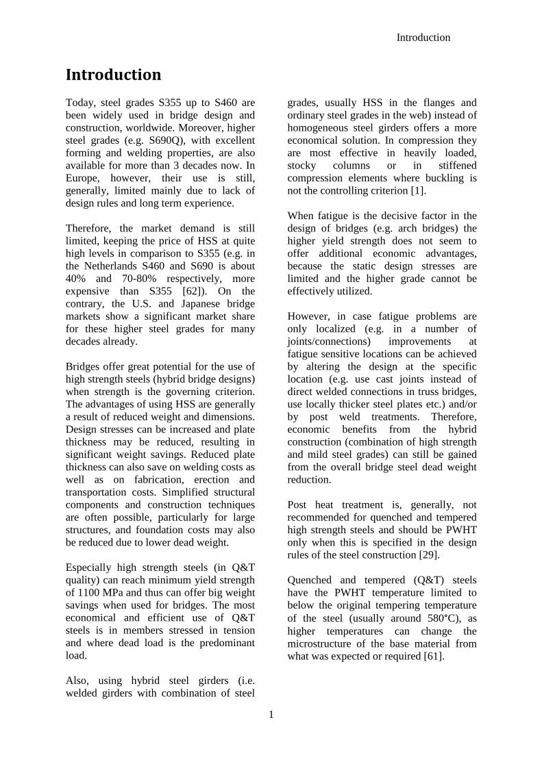
Today, steel grades S355 up to S460 are
been widely used in bridge design and
construction, worldwide. Moreover, higher
steel grades (e.g. S690Q), with excellent
forming and welding properties, are also
available for more than 3 decades now. In
Europe, however, their use is still,
generally, limited mainly due to lack of
design rules and long term experience.
Therefore, the market demand is still
limited, keeping the price of HSS at quite
high levels in comparison to S355 (e.g. in
the Netherlands S460 and S690 is about
40% and 70-80% respectively, more
expensive than S355 [62]). On the
contrary, the U.S. and Japanese bridge
markets show a significant market share
for these higher steel grades for many
decades already.
Bridges offer great potential for the use of
high strength steels (hybrid bridge designs)
when strength is the governing criterion.
The advantages of using HSS are generally
a result of reduced weight and dimensions.
Design stresses can be increased and plate
thickness may be reduced, resulting in
significant weight savings. Reduced plate
thickness can also save on welding costs as
well as on fabrication, erection and
transportation costs. Simplified structural
components and construction techniques
are often possible, particularly for large
structures, and foundation costs may also
be reduced due to lower dead weight.
Especially high strength steels (in Q&T
quality) can reach minimum yield strength
of 1100 MPa and thus can offer big weight
savings when used for bridges. The most
economical and efficient use of Q&T
steels is in members stressed in tension
and where dead load is the predominant
load.
Also, using hybrid steel girders (i.e.
welded girders with combination of steel
grades, usually HSS in the flanges and
ordinary steel grades in the web) instead of
homogeneous steel girders offers a more
economical solution. In compression they
are most effective in heavily loaded,
stocky columns or in stiffened
compression elements where buckling is
not the controlling criterion [1].
When fatigue is the decisive factor in the
design of bridges (e.g. arch bridges) the
higher yield strength does not seem to
offer additional economic advantages,
because the static design stresses are
limited and the higher grade cannot be
effectively utilized.
However, in case fatigue problems are
only localized (e.g. in a number of
joints/connections) improvements at
fatigue sensitive locations can be achieved
by altering the design at the specific
location (e.g. use cast joints instead of
direct welded connections in truss bridges,
use locally thicker steel plates etc.) and/or
by post weld treatments. Therefore,
economic benefits from the hybrid
construction (combination of high strength
and mild steel grades) can still be gained
from the overall bridge steel dead weight
reduction.
Post heat treatment is, generally, not
recommended for quenched and tempered
high strength steels and should be PWHT
only when this is specified in the design
rules of the steel construction [29].
Quenched and tempered (Q&T) steels
have the PWHT temperature limited to
below the original tempering temperature
of the steel (usually around 580°C), as
higher temperatures can change the
microstructure of the base material from
what was expected or required [61].

Introduction
2
Moreover, using high strength steel (HSS)
enhances economy in the first place but
also contributes in saving resources. A
structure in HSS uses less steel for a
certain application than one in mild steel.
This study aims to present the potential
advantages that high strength steels (HSS)
have to offer in case of bridges, but also
possible disadvantages. Special attention is
paid to high strength steel grades up to
S700 (700 MPa minimum yield strength)
in quenched and tempered condition
(Q&T).
This thesis is divided into two main parts
(Part 1 and Part 2):
In Part 1, a literature survey is initially
performed (Part 1A) based on scientific
documentation and relevant sites found on
the Internet. Its purpose is to collect
information from previous studies,
experimental projects and fabricators,
utilizing HSS for application in bridges,
around the world. Then in Part 1B, a long
span (L= 105 m) roadway bridge is chosen
as a case study (the ‘Schellingwouderbrug’
in the Netherlands) and preliminary
designs for three bridge types are
presented (a single box girder bridge, a
warren type truss girder bridge and arch
girder bridge with vertical hangers). High
strength steel S690 with minimum fy = 690
MPa is applied in members with very high
stresses (e.g. chord members in the truss
bridge) and S355 everywhere else (hybrid
design concept). The design criteria that
have been studied are strength, stability
and fatigue.
In Part 2, the preliminary design
alternatives are compared on a cost basis
(based on calculated steel self-weight and
required maximum plate thicknesses) and
one is chosen and designed in more detail.
It is then checked, by estimating total
costs, whether the hybrid design with high
strength steel grade S690 will lead to a
more economical bridge solution in
comparison to an equivalent homogeneous
(completely out of S355 steel grade)
bridge design. European standards have
been used throughout the whole design
phase.
Comparing costs between the two hybrid
alternative designs (for the same bridge
type) and their equivalent homogeneous
designs, it has been found that the
developed hybrid designs (combination of
S355 and S690) for the
‘Schellingwouderbrug’, result in
significant weight savings in comparison
to their equivalent homogeneous (only
S355) bridge designs (even up to 65% in
some cases).
The high price for S690 (currently ≈70-
75% more expensive than S355) leads to
higher material costs (up to 4% higher) for
the hybrid designs. Nevertheless, the
weight reduction in hybrid designs has a
positive impact on the reduction of total
costs (up to 6% lower) including
fabrication, transportation, erection and
maintenance costs.
3
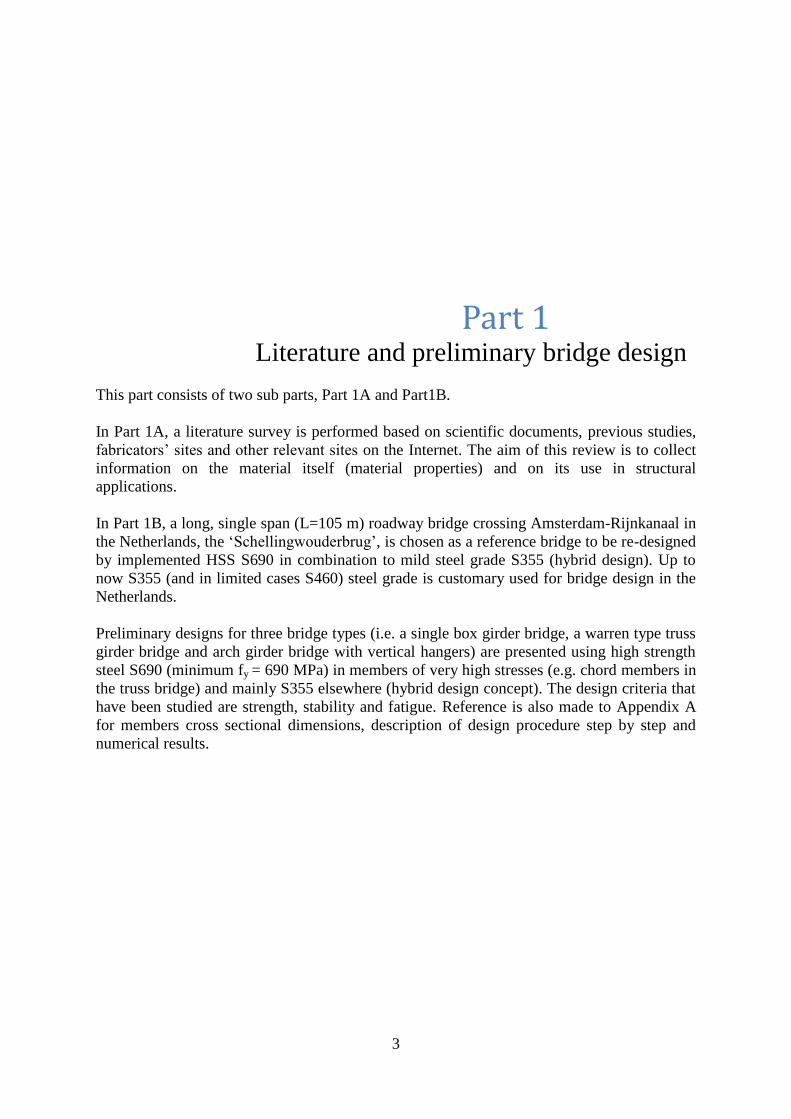
Part 1 Literature and preliminary bridge design
This part consists of two sub parts, Part 1A and Part1B.
In Part 1A, a literature survey is performed based on scientific documents, previous studies,
fabricators’ sites and other relevant sites on the Internet. The aim of this review is to collect
information on the material itself (material properties) and on its use in structural
applications.
In Part 1B, a long, single span (L=105 m) roadway bridge crossing Amsterdam-Rijnkanaal in
the Netherlands, the ‘Schellingwouderbrug’, is chosen as a reference bridge to be re-designed
by implemented HSS S690 in combination to mild steel grade S355 (hybrid design). Up to
now S355 (and in limited cases S460) steel grade is customary used for bridge design in the
Netherlands.
Preliminary designs for three bridge types (i.e. a single box girder bridge, a warren type truss
girder bridge and arch girder bridge with vertical hangers) are presented using high strength
steel S690 (minimum fy = 690 MPa) in members of very high stresses (e.g. chord members in
the truss bridge) and mainly S355 elsewhere (hybrid design concept). The design criteria that
have been studied are strength, stability and fatigue. Reference is also made to Appendix A
for members cross sectional dimensions, description of design procedure step by step and
numerical results.
Part 1A
4
Part 1A Literature survey
In Part 1A (chapters 1, 2, 3, and 4), a literature survey is performed based on scientific
documents, previous studies, fabricators’ sites and other relevant sites on the Internet. The
aim of this review is to collect information on the material itself (material properties) and also
on its use in structural applications. The most interesting points from this review are
summarized in chapter 4.
Part 1A: Literature survey Chapter 1: High strength steel material
5
1 Material
1.1 High Strength Steel (HSS)
1.1.1 General
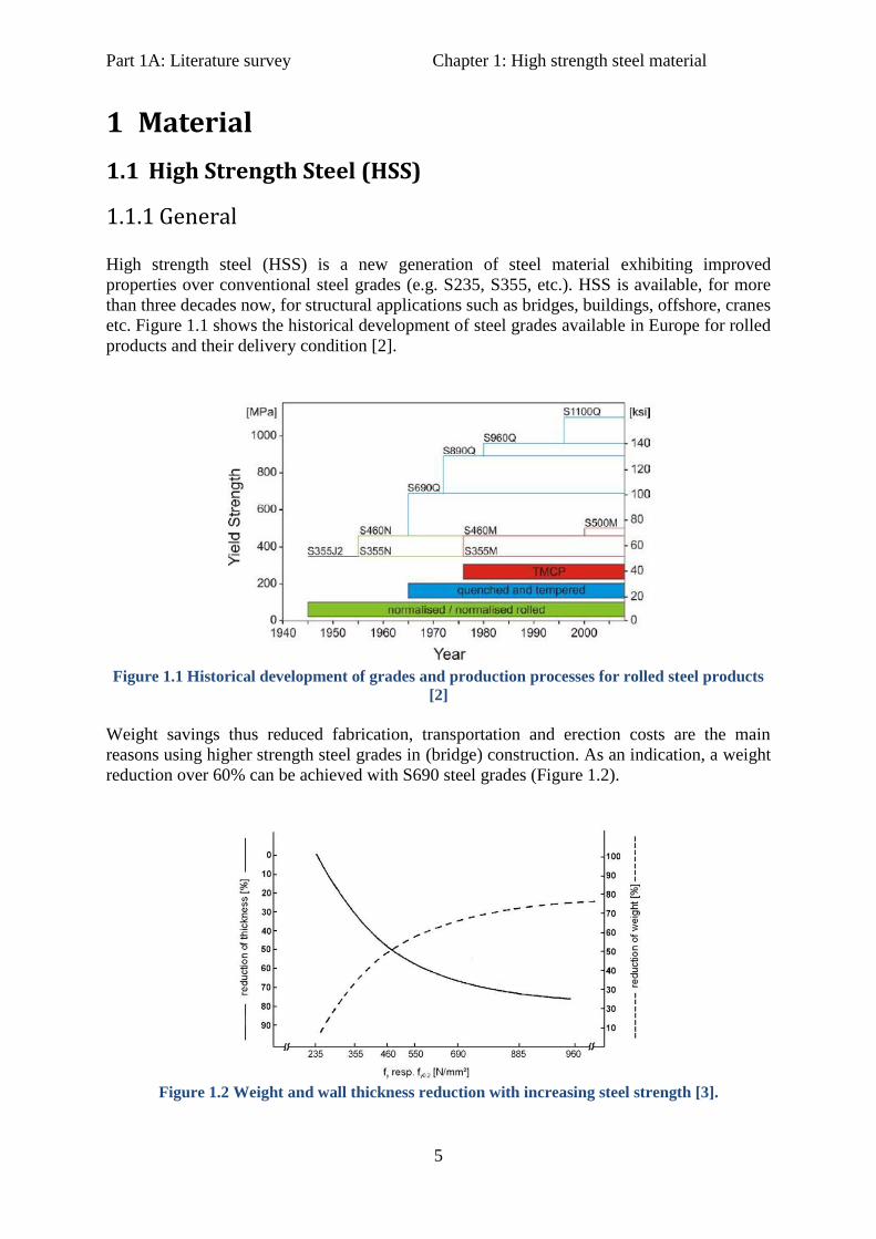
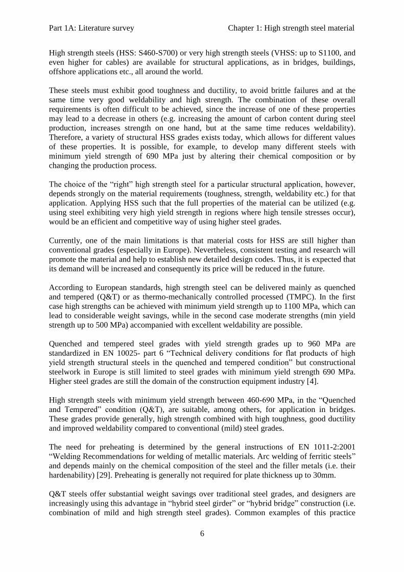
High strength steel (HSS) is a new generation of steel material exhibiting improved
properties over conventional steel grades (e.g. S235, S355, etc.). HSS is available, for more
than three decades now, for structural applications such as bridges, buildings, offshore, cranes
etc. Figure 1.1 shows the historical development of steel grades available in Europe for rolled
products and their delivery condition [2].
Figure 1.1 Historical development of grades and production processes for rolled steel products
[2]
Weight savings thus reduced fabrication, transportation and erection costs are the main
reasons using higher strength steel grades in (bridge) construction. As an indication, a weight
reduction over 60% can be achieved with S690 steel grades (Figure 1.2).
Figure 1.2 Weight and wall thickness reduction with increasing steel strength [3].
Part 1A: Literature survey Chapter 1: High strength steel material
6
High strength steels (HSS: S460-S700) or very high strength steels (VHSS: up to S1100, and
even higher for cables) are available for structural applications, as in bridges, buildings,
offshore applications etc., all around the world.
These steels must exhibit good toughness and ductility, to avoid brittle failures and at the
same time very good weldability and high strength. The combination of these overall
requirements is often difficult to be achieved, since the increase of one of these properties
may lead to a decrease in others (e.g. increasing the amount of carbon content during steel
production, increases strength on one hand, but at the same time reduces weldability).
Therefore, a variety of structural HSS grades exists today, which allows for different values
of these properties. It is possible, for example, to develop many different steels with
minimum yield strength of 690 MPa just by altering their chemical composition or by
changing the production process.
The choice of the “right” high strength steel for a particular structural application, however,
depends strongly on the material requirements (toughness, strength, weldability etc.) for that
application. Applying HSS such that the full properties of the material can be utilized (e.g.
using steel exhibiting very high yield strength in regions where high tensile stresses occur),
would be an efficient and competitive way of using higher steel grades.
Currently, one of the main limitations is that material costs for HSS are still higher than
conventional grades (especially in Europe). Nevertheless, consistent testing and research will
promote the material and help to establish new detailed design codes. Thus, it is expected that
its demand will be increased and consequently its price will be reduced in the future.
According to European standards, high strength steel can be delivered mainly as quenched
and tempered (Q&T) or as thermo-mechanically controlled processed (TMPC). In the first
case high strengths can be achieved with minimum yield strength up to 1100 MPa, which can
lead to considerable weight savings, while in the second case moderate strengths (min yield
strength up to 500 MPa) accompanied with excellent weldability are possible.
Quenched and tempered steel grades with yield strength grades up to 960 MPa are
standardized in EN 10025- part 6 “Technical delivery conditions for flat products of high
yield strength structural steels in the quenched and tempered condition” but constructional
steelwork in Europe is still limited to steel grades with minimum yield strength 690 MPa.
Higher steel grades are still the domain of the construction equipment industry [4].
High strength steels with minimum yield strength between 460-690 MPa, in the “Quenched
and Tempered” condition (Q&T), are suitable, among others, for application in bridges.
These grades provide generally, high strength combined with high toughness, good ductility
and improved weldability compared to conventional (mild) steel grades.
The need for preheating is determined by the general instructions of EN 1011-2:2001
“Welding Recommendations for welding of metallic materials. Arc welding of ferritic steels”
and depends mainly on the chemical composition of the steel and the filler metals (i.e. their
hardenability) [29]. Preheating is generally not required for plate thickness up to 30mm.
Q&T steels offer substantial weight savings over traditional steel grades, and designers are
increasingly using this advantage in “hybrid steel girder” or “hybrid bridge” construction (i.e.
combination of mild and high strength steel grades). Common examples of this practice
Part 1A: Literature survey Chapter 1: High strength steel material
7
include beams with high strength flanges and standard strength web, and steel tanks with
higher strength steel for the more heavily loaded lower sections, thereby maintaining a
constant wall thickness for simplified fabrication. This hybrid approach gives high strength
steel a crucial cost advantage [1].
In Europe, a variety of HSS with yield strengths from 460 to 690 MPa are available for
bridge applications, although still not widely used. The two main reasons for this drawback
are the lack of detailed design codes, especially for grades between S700 and S1100, and also
the higher material costs compared to conventional steel grades. So far, European design
Standards have developed additional design rules and specifications to extend existing design
rules covering steel grades up to S700 only (Eurocode 3 - Design of steel structures - Part 1-
12: Additional rules for the extension of EN 1993 up to steel grades S700 (2007)).
Ongoing testing and research contributes in gaining more experience on the structural
behaviour of bridge components made with these steel grades, and extend further their use for
bridge design.
On the contrary, bridges using HSS in U.S and Japan exist for several decades already.
Use of HSS for bridge construction, in Japan, dates back to 1960 (Miki and al. 2002). Several
hundred bridges have been constructed using 500 MPa and 600 MPa yield strength steel, and
steel with nominal yield strength of 800 MPa has also been used in several projects. These
steels typically require preheating between 100-120 ºC before welding and sometimes post-
weld treatment to avoid hydrogen assisted cracking of the weld (cold cracking). In 1992, a
new steel grade (fy=800 MPa) was developed that requires preheating at 50 ºC (Miki and al.
2002) [5].
In 1992, in U.S. a new type of steel, known as high-performance steel (HPS) was developed.
High Performance (Weathering) Steel, with yield strength between HPS 70W (485MPa) and
HPS 120W (827 MPa), has been developed in the USA over the last decade. They provide
high strength, high toughness, good weldability and improved fatigue and corrosion
resistance [6].
1.1.2 High strength steel types
Depending on their structural properties, chemical composition or delivery condition, many
different types/categories exist, which usually referred as high strength steels (HSS) or high
performance steels (HPS).
All these different steel types, however, have more or less similar properties, in the sense
that, they refer to high strength steels with better toughness, improved weldability, higher
strengths and/or improved corrosion resistance (in case of high performance weathering
steels).
Generally, their chemical composition and quality depends strongly on the production
process, controlled by the manufacturer, and also on the processes in the fabrication shop
(cutting, drilling, welding etc.) to obtain the final product. In any case, it must be ensured,
that they all comply with (or are superior of) the specifications provided by the relative
international quality standard (American (ASTM), European (EN), Japanese (JIS), etc.).

Part 1A: Literature survey Chapter 1: High strength steel material
8
Focused mainly on the latest developments in steels for design of bridges [7], several steel
types/categories are briefly described in this study. All these types of high strength steel, and
many others, are available nowadays, to produce stronger, lighter and more slender bridges.
1.1.2.1 HIGH STRENGTH LOW ALLOY STEEL (HSLA) OR MICROALLOYED STEELS
(MA)
Microalloyed (MA) or High Strength Low Alloy (HSLA) steels ([8], [9], and [10]) constitute
an important category of steels estimated to be around 12% of total world steel production
[8]. High Strength Low Alloy steels contain a low percentage of microalloying elements
(below 0.15% in total) and vary from other steels in that, they are not made to meet a specific
chemical composition, but rather to specific mechanical properties. They typically contain
0.07 to 0.12% carbon, up to 2% manganese and small additions of niobium, vanadium and
titanium (usually max. 0.1%) in various combinations. High-strength low-alloy (HSLA)
steels, or microalloyed steels, are designed to provide better mechanical properties and/or
greater resistance to atmospheric corrosion than conventional carbon steels [8]. The material
is preferably produced by a thermomechanical rolling process, which maximizes grain
refinement as a basis for improved mechanical properties. Grain refinement and precipitation
strengthening are the primary mechanisms to increase yield strength of microalloyed steels,
while maintaining desired levels of ductility and weldability. Furthermore, due to their higher
strength and toughness HSLA steels usually require 25 to 30% more power to form, as
compared to carbon steels.
A special type of HSLA steels is HSLA-V [11]. This low alloy steel is intended to represent
those steel grades where a small addition of vanadium (less than 0.12%) provides enhanced
strength over standard low C-Mn steels, while meeting or even exceeding all requirements for
ductility, weldability and toughness. They are usually supplied in the as-rolled or as-forged
condition, eliminating the need for subsequent heat treatments. This negates the need for
higher alloy contents of Cr, Ni and Mo (hence “Low Alloy”) and also provides significant
energy savings. It has many applications in structural engineering and especially for bridges
has already been used in different types (long span truss, non-standard fixed bridge,
deployable bridge, suspension components). Finally, steel manufacturers producing HSLA-V
steel, experience lower operating costs compared to C-Mn steels, due to the unique
metallurgical characteristics of vanadium in the microstructure and metalworking technology.
1.1.2.2 HIGH PERFORMANCE STEEL (HPS)
HPS developed in U.S., Europe and Japan, have nominal yield strengths between 485-
900 MPa and exhibit excellent ductility, toughness and corrosion resistance. HPS can be
welded with greater ease than many steels developed in the past [5].
In 1992, AISI partnered with the Carderock Division, Naval Surface Warfare Centre and the
Federal Highway Administration (FHWA) to develop new and improved steel alternatives for
bridges. The result was a new type of steel, known as high-performance steel (HPS), which
provided up to 18% cost savings and up to 28% weight savings when compared with
traditional steel bridge design materials. They also have improved fatigue and corrosion-
resistance properties [12].
Part 1A: Literature survey Chapter 1: High strength steel material
9
HPS 70W (485MPa) and HPS 120W (827MPa), has also been developed in the USA over the
last decade. The key features for this steel is high strength, high toughness, good weldability
and ease of fabrication (due to a low carbon equivalent), adequate elongation and yield to
tensile strength ratio for ductility and enhanced durability (corrosion resistance is superior to
weathering steels currently used) [13]. When produced by quenching and tempering (Q&T),
that poses limitations to the product length. However, production by thermo-mechanical
controlled processing (TMCP) is also possible.
1.1.2.3 HIGH STRENGTH WEATHERING STEEL (W)
High strength weathering steels are high strength low alloy steels, which under certain
atmospheric conditions (humidity and oxygen should always be present) give an enhanced
resistance to rusting compared to that of ordinary carbon manganese steels by forming a
protective layer on the outer surface. They are of particular interest to the artists and the
designers. The best known of these steels is COR-TEN® an alloy developed by the American
USX Corporation. Weathering steel bridges do not require painting. Periodic inspection and
cleaning should be the only maintenance required to ensure the bridge continues to perform
satisfactorily. Hence, weathering steel bridges are ideal where access is difficult or
dangerous, and where future disruption needs to be minimized.
Cost savings from the elimination of the protective paint system outweigh the additional
material costs. Typically, the initial costs of weathering steel bridges are approximately 5%
lower than conventional painted steel alternatives [7]. In addition, limited maintenance
requirements of weathering steel bridges, greatly reduces both the direct costs of the
maintenance operations, and the indirect costs of traffic delays or rail possessions.
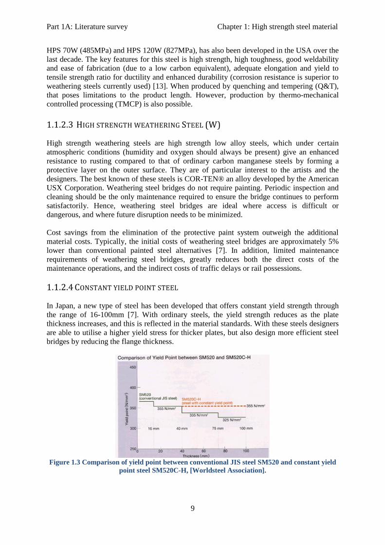
1.1.2.4 CONSTANT YIELD POINT STEEL
In Japan, a new type of steel has been developed that offers constant yield strength through
the range of 16-100mm [7]. With ordinary steels, the yield strength reduces as the plate
thickness increases, and this is reflected in the material standards. With these steels designers
are able to utilise a higher yield stress for thicker plates, but also design more efficient steel
bridges by reducing the flange thickness.
Figure 1.3 Comparison of yield point between conventional JIS steel SM520 and constant yield
point steel SM520C-H, [Worldsteel Association].

Part 1A: Literature survey Chapter 1: High strength steel material
10
1.1.2.5 HIGH TOUGHNESS STEEL
Generally, the toughness of steel products decreases at low temperature and the steel becomes
susceptible to brittle fracture. However, the use of high toughness steel plates allows the use
of steel for bridges in very cold regions. This steel provides two main benefits: Firstly, cold
forming becomes possible with smaller bending radius, and secondly, the steel products can
be used in cold regions (toughness is not reduced even at very low temperatures avoiding
brittle fracture), Figure 1.4
Figure 1.4 Comparison of toughness performance of high toughness steel and conventional steel
[Worldsteel Association].
1.1.2.6 BRIDGE HIGH PERFORMANCE STEELS (BHS)
High performance steel for bridges (BHS) was recently developed in Japan. BHS is defined
as a steel material superior to conventional steel materials for bridge structures in terms of
strength, fracture toughness, weldability, workability and corrosion resistance which are
required for bridges and has its properties optimized for application to bridges [16]. Honshu-
Shikoku bridge project is a good example of effectiveness of a BHS with tensile strength of
780 MPa (680 MPa yield strength).
The Society for the study of High-Performance Steel Application- established at the Creative
Project Research group in the Tokyo Institute of Technology-, has discussed the performance
requirements of steel bridges and the specifications of steel materials for steel bridges as part
of an industrial academic project involving steelmakers and bridge fabricators [33].
For plate girder bridges it was found that increasing the yield strength the weight decreases
but exceeding yield strength of 500 MPa will not always be effectively used in design.
Therefore, it was proposed that yield strength of 500 MPa is approximately, the upper limit
that can effectively be used in girder bridge design and should be adopted as the basic yield
strength for BHS. For suspension and cable stayed bridges (bridge types in which reducing
Part 1A: Literature survey Chapter 1: High strength steel material
11
the dead load of the superstructure has a significant effect on bridge economics), the same
study, proposed a yield strength of 700 MPa as the upper limit for BHS.
1.1.3 Chemical composition of structural HSS
Depending on the material properties required for a specific application, the amount and
types of alloying elements vary in chemical composition of HSS. These variations in
chemical composition accompanied with high quality in fabrication process, determine the
final properties of high strength steel grades. It is not the aim of this study to refer extensively
in the chemical composition of all different types/categories of high strength steels mentioned
in the previous section, of course. Some general information has already been provided for
HSLA steels, anyway.
Special attention, however, is paid on quenched and tempered structural steels (Q&T). That is
because; they provide high strength, improved toughness properties at low temperatures, very
good weldability and sufficient ductility to be used for bridge design. They also offer
substantial weight, thus cost, savings and are covered by the European standards. Quality
standard EN 10025-6 cover these steels up to grades S960 but design standard EN 1993-1-12
gives additional design rules only up to S700 steel grades. Therefore, for practical reasons
this study focuses on the range of S500-S700 (Q&T), which are covered by the Eurocodes.
1.1.3.1 CHEMICAL COMPOSITION OF HSS IN Q&T CONDITION
Q&T steels offer many advantages which, in the right circumstances, can generate significant
cost savings. Especially for bridges, key design benefits include longer or lighter spans and
greater load carrying capacity. They provide high strength to weight ratios, very good
weldability, improved toughness and sufficient deformation capacity (especially where
overmatched welds are used). Financial benefits can also be realized through reduced
transportation and lifting costs (reduced weight), material savings (smaller/lighter sections)
and reduced weld volumes (thinner plates).
Some typical quenched and tempered steel grades for structural applications are the steel
grades S500, S550, S620, S690, S890 and S960 [EN10025-6]. Quenched and tempered high
strength structural steels (usually up to S690) are ideal for applications with heavy sections
and heavy live loads (e.g. long span bridges), where weight reduction is important.
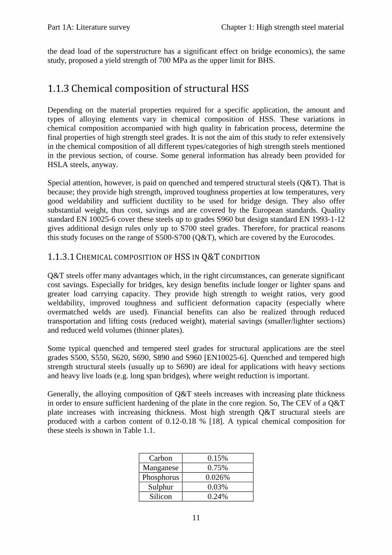
Generally, the alloying composition of Q&T steels increases with increasing plate thickness
in order to ensure sufficient hardening of the plate in the core region. So, The CEV of a Q&T
plate increases with increasing thickness. Most high strength Q&T structural steels are
produced with a carbon content of 0.12-0.18 % [18]. A typical chemical composition for
these steels is shown in Table 1.1.
Carbon 0.15%
Manganese 0.75%
Phosphorus 0.026%
Sulphur 0.03%
Silicon 0.24%
Part 1A: Literature survey Chapter 1: High strength steel material
12
Nickel 0.85%
Chromium 0.5%
Molybdenum 0.45%
Vanadium 0.05%
Copper 0.31%
Table 1.1 Typical chemical composition for quenched and tempered steels
[SteelTalk.com, [14]].
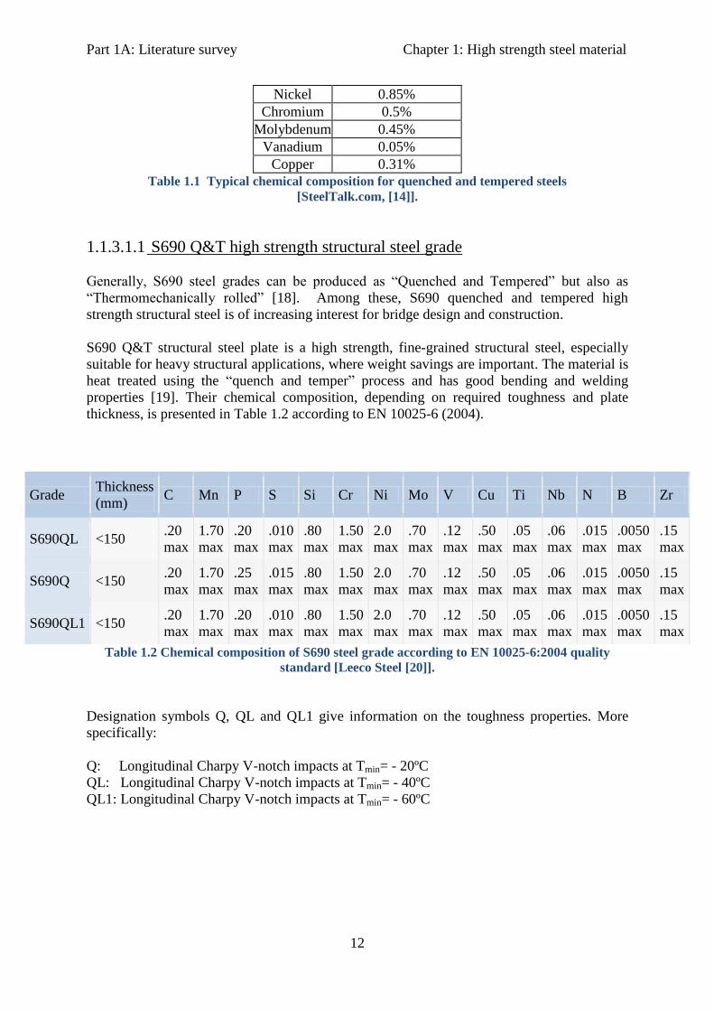
1.1.3.1.1 S690 Q&T high strength structural steel grade
Generally, S690 steel grades can be produced as “Quenched and Tempered” but also as
“Thermomechanically rolled” [18]. Among these, S690 quenched and tempered high
strength structural steel is of increasing interest for bridge design and construction.
S690 Q&T structural steel plate is a high strength, fine-grained structural steel, especially
suitable for heavy structural applications, where weight savings are important. The material is
heat treated using the “quench and temper” process and has good bending and welding
properties [19]. Their chemical composition, depending on required toughness and plate
thickness, is presented in Table 1.2 according to EN 10025-6 (2004).
Grade Thickness
(mm) C Mn P S Si Cr Ni Mo V Cu Ti Nb N B Zr
S690QL <150 .20
max
1.70
max
.20
max
.010
max
.80
max
1.50
max
2.0
max
.70
max
.12
max
.50
max
.05
max
.06
max
.015
max
.0050
max
.15
max
S690Q <150 .20
max
1.70
max
.25
max
.015
max
.80
max
1.50
max
2.0
max
.70
max
.12
max
.50
max
.05
max
.06
max
.015
max
.0050
max
.15
max
S690QL1 <150 .20
max
1.70
max
.20
max
.010
max
.80
max
1.50
max
2.0
max
.70
max
.12
max
.50
max
.05
max
.06
max
.015
max
.0050
max
.15
max
Table 1.2 Chemical composition of S690 steel grade according to EN 10025-6:2004 quality
standard [Leeco Steel [20]].
Designation symbols Q, QL and QL1 give information on the toughness properties. More
specifically:
Q: Longitudinal Charpy V-notch impacts at Tmin= - 20ºC
QL: Longitudinal Charpy V-notch impacts at Tmin= - 40ºC
QL1: Longitudinal Charpy V-notch impacts at Tmin= - 60ºC
Part 1A: Literature survey Chapter 1: High strength steel material
13
1.1.4 Properties of High Strength Steels
1.1.4.1 MECHANICAL PROPERTIES
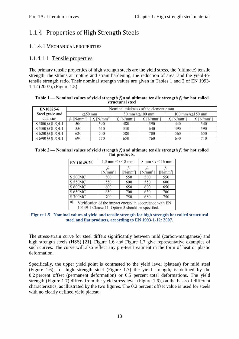
1.1.4.1.1 Tensile properties
The primary tensile properties of high strength steels are the yield stress, the (ultimate) tensile
strength, the strains at rupture and strain hardening, the reduction of area, and the yield-to-
tensile strength ratio. Their nominal strength values are given in Tables 1 and 2 of EN 1993-
1-12 (2007), (Figure 1.5).
Figure 1.5 Nominal values of yield and tensile strength for high strength hot rolled structural
steel and flat products, according to EN 1993-1-12: 2007.
The stress-strain curve for steel differs significantly between mild (carbon-manganese) and
high strength steels (HSS) [21]. Figure 1.6 and Figure 1.7 give representative examples of
such curves. The curve will also reflect any pre-test treatment in the form of heat or plastic
deformation.
Specifically, the upper yield point is contrasted to the yield level (plateau) for mild steel
(Figure 1.6); for high strength steel (Figure 1.7) the yield strength, is defined by the
0.2 percent offset (permanent deformation) or 0.5 percent total deformations. The yield
strength (Figure 1.7) differs from the yield stress level (Figure 1.6), on the basis of different
characteristics, as illustrated by the two figures. The 0.2 percent offset value is used for steels
with no clearly defined yield plateau.

Part 1A: Literature survey Chapter 1: High strength steel material
14
Figure 1.6 Typical stress-strain curve for mild steels (Geschwindner et al., 1994)
Figure 1.7 Stress strain curve for high strength steels (Geschwindner et al., 1994)
1.1.4.1.2 Toughness
High strength steels show much improved toughness properties compared to conventional
steel grades even at very low temperatures (transition to brittle fracture occurs at lower
temperatures than conventional steel grades).
The Charpy-V notch impact test is used as a measure of toughness of structural steel where
the test temperature and the minimum absorbed energy are specified, although Charpy results
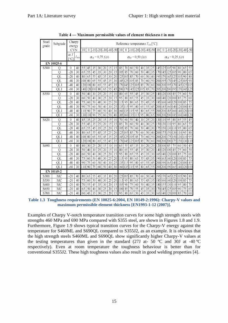
cannot be considered to be directly relevant to structural behaviour [15]. Table 1.3 specifies
maximum element thickness depending on the steel grade and the minimum Charpy-V
energy values. Grades taken from this table and satisfying the conditions given in
EN1993-1-10 for the lowest temperature, are assumed to have sufficient toughness and no
further testing is needed against brittle fracture [EN 1993-1-1 (2006)].
Part 1A: Literature survey Chapter 1: High strength steel material
15
Table 1.3 Toughness requirements (EN 10025-6:2004, EN 10149-2:1996): Charpy-V values and
maximum permissible element thickness [EN1993-1-12 (2007)].
Examples of Charpy V-notch temperature transition curves for some high strength steels with
strengths 460 MPa and 690 MPa compared with S355 steel, are shown in Figures 1.8 and 1.9.
Furthermore, Figure 1.9 shows typical transition curves for the Charpy-V energy against the
temperature for S460ML and S690QL compared to S355J2, as an example. It is obvious that
the high strength steels S460ML and S690QL show significantly higher Charpy-V values at
the testing temperatures than given in the standard (27J at- 50 ºC and 30J at -40 ºC
respectively). Even at room temperature the toughness behaviour is better than for
conventional S355J2. These high toughness values also result in good welding properties [4].

Part 1A: Literature survey Chapter 1: High strength steel material
16
Figure 1.8 Charpy V-notch temperature transition curves for some HSS, [22]
Figure 1.9 Charpy-V temperature transition curves for S460M and, S690QL compared to
S355J2 [4].
1.1.4.1.3 Ductility
The requirements for ductility ensure that brittle failures are avoided (i.e. inelastic
deformations must be sufficiently large). The carbon content plays an important role here.
Increasing the carbon content produces a material with higher strength but lower ductility.
Therefore, the carbon content should be kept between 0.15-0.30 % for all structural
steels [23]. In case of HSS is possible to keep the carbon content at very low levels usually
around 0.15% ensuring high strengths at the same time. The quality of HSS meets similar
standards to conventional steel grades. That is also verified by experimental research.

Part 1A: Literature survey Chapter 1: High strength steel material
17
Uni-axial tension tests on HSS coupons have shown that these steels can achieve elongation
of up to 20%, which is considered excellent [24]. Tests on beam to column bolted
connections (S355) with end plates (S690) have shown that the rotation capacity of
specimens using HSS satisfy high deformation demands. Furthermore, rotation capacities of
40 mrad (it is generally accepted that a minimum of 35-40 mrad ensures sufficient rotation
capacity of a bolted joint in a partial-strength scenario) and above, were achieved with
thinner end plates. However, simple beam analysis with actual joint behaviour has shown that
the efficiency of HSS moment connections has no correspondence to the improvement in
quality, and the deformation demands of these connections are higher than for mild steel
grades.
High strength steels with a tensile to yield strength ratio of 1.05 are considered less ductile
than mild structural steel. Therefore it is believed they are suitable only for elastic analysis.
Figure 1.10 (b) shows why HSS are considered to be more sensitive to local ductility
demands than ordinary steel grades. However, extensive experimental research on plates with
holes and bolted connections made of steel grade S690 confirmed that a low fu/fy ratio does
not affect local ductility significantly.
Figure 1.10 (a) Stress strain curves for different steel grades; (b) Load-deflection curves for
different steel grades [3].
Tables 1 and 2 of EN 1993-1-12:2007 (Figure 1.5) specify the nominal values of the yield
strength (fy) and the ultimate tensile strength (fu) for hot rolled high strength structural steel.
It is stated that steels included in these tables can be assumed to satisfy the ductility
requirements. Generally the same rules for ductility, as for normal structural steel grades,
hold for HSS with the limits of the two first requirements somewhat relaxed. More
specifically: fu/fy ≥ 1.05 and elongation at failure not less than 10% [EN 1993-1-12 (2007)].
The critical part of the steel manufacturing is to control the processing parameters so that the
microstructure and, hence, the strength-elongation balance could be optimized. Figure
1.11gives an indication on ductility properties (total elongation %) based on the tensile
strength of different structural steel grades.

Part 1A: Literature survey Chapter 1: High strength steel material
18
Figure 1.11 Ductility of structural steels compared to their tensile strength [25].
1.1.4.2 TECHNOLOGICAL PROPERTIES
Technological properties of HSS include weldability and formability. Once more, high
strength steels (S460-S700) in quenched and tempered condition are mainly of interest in this
study.
1.1.4.2.1 Weldability
High strength steels (HSS) show generally improved weldability compared to conventional
structural steels and they are suitable for all current welding methods. Generally, no
preheating is required for plate thickness up to 30 mm. However, the temperature of the
material should be at least RT for welding.
The need for preheating, however, is determined by the general instructions of EN 1011-2
and depends mainly on the chemical composition of the steel and the filler metals (i.e. their
hardenability) [29].
Below preheating recommended temperatures for S690 QL1 steel grade (source: steel
supplier AJ Marshall, UK) are given as an example:
20mm – 40mm: 75°C
40-60 mm: 100°C
>60mm 150°C
In general, as the parent metal strength increases, greater precautions are needed to ensure
that welding procedure is satisfactory, see also Figure 1.12.

Part 1A: Literature survey Chapter 1: High strength steel material
19
Figure 1.12 Total weld heat input for welding Q&T steels [60]
The shaded area in Figure 1.12 denotes a permissible heat input ‘window’ limited on the low
energy side by the risk of excessive energy and cold cracking. On the other side the heat input
is limited by the loss of strength and hardness. This ‘window’ for the arc energy input is
getting smaller as the strength of base material increases [60].
Variations in the welding process such as steel dimensions, weld geometry, heat input and
steel chemical composition all influence the resulting microstructure. Nomograms involving
thermal severity- joint thickness (mm), heat input of the weld (KJ/mm) and weld preheat
required (ºC) are often used to indicate the necessary welding procedure to be followed to
produce a sound crack free joint in relation to the particular composition of the steel used
which is usually related to carbon equivalent value [15].
Carbon equivalent (CEV or CE) is the most common measure for weldability, which is used
to assess the combined effect of carbon and the other chemical elements on the cracking
susceptibility of the material. Generally, low values for CE are important for good
weldability. Various CE-formulas are available, but for structural steel is usually described by
the following equation, which is the formula, proposed by the International Institute of
Welding (IIW):
CE = C + Μn/6 + (Cr + Mo + V)/5 + (Ni + Cu)/15
As an alternative approach adopted from some countries is the Graville diagram shown in
Figure 1.13 which separates the steels into three zones rated by their ease of weldability-zone
I easily weldable, zone II weldable with care, and zone III difficult to weld [15]. From this
diagram can be seen that with increasing carbon equivalent the weldability decreases but it
also emphasises the extremely important effect of carbon content on weldability. Reducing
the carbon content of steel is the most effective way to improve its weldability [15].

Part 1A: Literature survey Chapter 1: High strength steel material
20
Figure 1.13 Weldability criteria, cracking susceptibility [15]
A very high carbon equivalent value indicates poor weldability and these steels are not
suitable for structural applications, where welding is very important to assure structural
safety. The CEV is also utilized to assess preheat requirements for a welded joint or
assembly, and to take into account the influence of hydrogen and joint restraint.
Finally, HSS are suitable for all current welding methods and they generally require little or
no preheat [CSEC Group]. Also post weld heat treatment (PWHT) is not recommended in
case of Q&T high strength steels [29].
1.1.4.2.2 Formability
The mechanical properties of the particular steel grade being formed, dictates the loads
required (higher grades require higher loads) for forming and the care that should be taken
during the process. New developments and production of fine grain structural steel (S690),
have allowed for HSS and VHSS to combine strength and weldability with excellent
formability. Strength and formability of these steel grades however, extend scope for
fabrication. For example, products may be manufactured by press forming rather than
welding. A major drawback fabricating HSS and VHSS is they tend to demonstrate a higher
“spring-back” during the process, which restricts workability.
To overcome similar limitations new innovative processes like hot forming (at elevated
temperatures on a hydraulic press and air cooling) or hydro-forming (at room temperature
with force of water or hydraulic fluids) are required. Quenched and tempered high strength
structural steels are suitable for both cold (at ambient temperatures) and hot forming.
Part 1A: Literature survey Chapter 1: High strength steel material
21
Another important consideration is that HSS material requires more energy. Two main
factors need to be considered. Firstly, increased forming tonnage in combination with
increased draw pad pressure requires higher energy; secondly, the higher-strength steel does
not have the same draw qualities as the previously used lower-grade steels. This could lead to
cracking at the forming radii and unacceptable thinning of the material as it is drawn. This
requires the operator to decrease the draw speed by slowing the press.
1.1.5 Production of HSS
Weldable structural steels can be delivered as “normalized (N)”, “quenched and tempered
(Q&T)”, or “thermo-mechanically controlled rolled (TM or TMPC)”. All heating, cooling
and processing methods affect the microstructure of steel. With classical hot rolling and
normalizing of the steel we can achieve moderate values of strength (up to 460 MPa yield
strength) and toughness. By quenching and tempering however, we can achieve yield
strengths up to 1100 MPa. TM rolled plates are available with minimum yield strength of 500
MPa. Higher steel grades (e.g. S690) are also possible by the TM-process but in a more
limited thickness.
The steel manufacturing process can be Basic-Oxygen-Furnace, Electric-Furnace, etc., and is
generally the option of the manufacturer. If production process is carefully controlled, the
properties such as hardness, ductility and tensile strength can be predetermined to fulfill a
variety of uses. The metal is finally shaped under temperature controlled conditions which
can alter its characteristics and strength.
In general, the strength of steel is controlled by its microstructure which varies according to
its chemical composition, its thermal history and the deformation process it undergoes during
its production process. The strength can be enhanced mainly in two ways: by grain
refinement (and precipitation hardening) (Figure 1.14) or by increasing the carbon content
(CE)-or carbon equivalent (CEV)-, (Figure 1.15). In case of grain refinement, the material
obtains high strength, accompanied with good toughness and excellent weldability, while
increasing the carbon content, makes the material more brittle.

Part 1A: Literature survey Chapter 1: High strength steel material
22
Figure 1.14 Microstructure of conventional normalized steel compared to TM, TM+ACC and
Q&T steels [26].
Figure 1.15 Effect of CE and steel processing route on plate strength.
Where,
N: Normalized
QT: Quenched and tempered
TM: Thermomechanically rolled
ACC: Accelerated cooled
DIC: Direct intensive cooled
In Figure 1.15 the relation between the carbon equivalent and the yield strength is plotted.
While raising the carbon-equivalent increases strength it also drastically reduces other
engineering properties (e.g. weldability). Figure 1.15 shows also that, the same yield strength
level is possible on different levels of carbon equivalent depending on the delivery conditions
of steel material. However, since welding is irreplaceable as a method of fabrication, the
Part 1A: Literature survey Chapter 1: High strength steel material
23
carbon-equivalent mechanism of steel strengthening cannot be used in many applications
requiring good weldability (e.g. bridges).
On the other hand, grain refinement and precipitation hardening, increase strength and also
improve toughness. Because these two dominant strengthening mechanisms operate in micro-
alloyed steels, their carbon content may be very low. This low-carbon content contributes to
excellent weldability.
In practice, grain refinement can be achieved during hot rolling by the interaction between
micro-alloying elements (niobium, vanadium, or titanium) and hot deformation. Grain
refinement may be further enhanced by accelerating cooling after the completion of hot
rolling.
Hot and Cold Rolling
There are various methods of forming steel into finished products, including hot forging, hot
and cold rolling, seamless tube making and welded tube making. The most widely used
process is hot rolling, which accounts for over 90% of all steel production. There are many
types of rolling processes, including flat rolling, foil rolling, ring rolling, roll bending, roll
forming, profile rolling, and controlled rolling.
Rolling is a metal forming process in which metal stock is passed through a pair of rolls.
Rolling is classified according to the temperature of the metal rolled. If the temperature of the
metal is above its re-crystallization temperature, then the process is termed as hot rolling. If
the temperature of the metal is below its re-crystallization temperature, the process is termed
as cold rolling. In terms of usage, hot rolling processes more tonnage than any other
manufacturing process and cold rolling processes the most tonnage out of all cold working
processes.
High strength steels produced in the Q&T method suitable for hot working only at
temperatures below 550ºC since very high temperature affects their mechanical properties
[29].
1.1.5.1 PRODUCTION OF Q&T HSS
By quenching and tempering, structural steels can reach minimum yield strength of 1100
MPa. This heat treatment applied subsequent to hot rolling, consists of an austenitisation,
followed by quenching and finally tempering [26].
Quenched and tempered steels are used for components subjected to high stresses where the
combination of high strength, wear-resistance and toughness are particularly important.
Quenching and tempering gives the materials their special properties. Temperature control
during quenching and tempering is essential to achieve the desired component properties;
however, it must be matched to the respective application.
Generally, the alloying composition of Q&T steels increases with increasing plate thickness
in order to ensure sufficient hardening of the plate in the core region. So, The CEV of a Q&T
plate increases with increasing thickness. Most high strength Q&T structural steels are
produced with a carbon content of 0.12-0.18 %. Figure 1.16 can explain why this is the most
favorable range. The martensite hardness increases linear with the carbon content.

Part 1A: Literature survey Chapter 1: High strength steel material
24
Figure 1.16 Influence of carbon content on hardness and yield strength of Martensite as
quenched and after tempered at two temperatures (T2>T1). Relation hardness and yield
strength is not perfectly linear and so the right y- axis serves for an estimation only.(Dillinger
Hütte, [18])
Quenching
Heat treatment process employed to produce high strength steels involves quickly cooling
austenized steel in a quenching medium like air, water or oil. Heat treatment results in the
formation of martensitic microstructure, which makes the steel not only extremely hard but
also brittle. However, by subjecting steels to heating or tempering (Q&T) after quenching, an
optimum combination of high strength and ductility can be achieved.
Tempering
Tempering is heat-treating of metal alloys, particularly steel, to reduce brittleness and restore
ductility. In tempering, steel is slowly heated to a temperature between 150 °C and 700 °C
(for appropriate toughness, tempering is performed at least at 550 °C), depending on desired
properties, in an oil or salt bath and held for about two hours and then allowed to air cool. As
steel is physically worked (e.g., rolling, wiredrawing, hammering), hardening takes place, and
it grows progressively more brittle.
Heating and quenching also increase hardness. Combined quench-and-temper heat-treating is
applied at many different cooling rates, holding times, and temperatures and is a very
important means of controlling the properties of steel. Strength and hardness, generally,
decrease with increasing tempering temperature and holding time. On the other hand, results
from tensile tests show that, elongation and area reduction increase as the tempering
temperature and holding time are increased, Figure 1.17 [27].

Part 1A: Literature survey Chapter 1: High strength steel material
25
Figure 1.17 Effect of tempering temperature and holding time on (a) tensile strength, (b)
hardness, (c) elongation and area reduction (ductility) of Q&T high strength steels [27].
In Figures 1.18 and 1.19 an example of 60 mm thick “Dillimax 890” (Q&T fine grained
structural steel with minimum yield strength of 890 MPa produced by Dillinger Hütte GTS)
steel is presented with respect to the effect of tempering temperatures on the strength and
toughness properties of the material.
Figure 1.18 Influence of increasing tempering temperatures on tensile properties of Dillimax
890 in 60 mm thickness [18]

Part 1A: Literature survey Chapter 1: High strength steel material
26
Figure 1.19 Influence of increasing tempering temperatures on the Charpy impact transition of
Dillimax 890 in 60 mm thickness [18]
1.1.6 Fabrication of HSS
Fabrication consists of cutting pieces of steel and connecting them together. The material is
generally obtained from rolling mills or stocks in the form of I-sections, channels, hollow
sections, angles or plates. The steel specified should be rationalized to use relatively few
section sizes and a common grade. The sections are being cut to length, drilled and welded as
necessary ready for assembly, and in most cases some protective treatment is applied against
corrosion.
Operations can include cleaning, sawing, shearing, punching, grinding, bending, drilling,
welding and the finishing of the steel. These involve extensive use of numerically controlled
processes which improve productivity and quality. Cranes are always involved for moving
material within the factory, but the use of mechanical conveyors is more efficient. There are
saws and guillotines, drills and punches, and facilities for flame cutting and welding, both by
hand and by machine.
Fabricator's shops vary both in the size of the facility and weight of material that they can
handle. The sophistication of the available equipment also varies. Increasingly, where
investment is available, operations are being automated and computer-controlled. This is
necessary, particularly, for fabricating higher strength materials.
In Europe only a limited number of fabricators can process and fabricate HSS mainly because
of the required investment. However, in a few years, as the market demand for the new steel
material will increase it will be essential that all fabricators invest in new equipment.
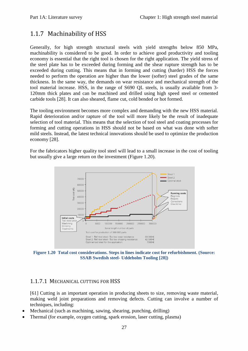
Part 1A: Literature survey Chapter 1: High strength steel material
27
1.1.7 Machinability of HSS
Generally, for high strength structural steels with yield strengths below 850 MPa,
machinability is considered to be good. In order to achieve good productivity and tooling
economy is essential that the right tool is chosen for the right application. The yield stress of
the steel plate has to be exceeded during forming and the shear rupture strength has to be
exceeded during cutting. This means that in forming and cutting (harder) HSS the forces
needed to perform the operation are higher than the lower (softer) steel grades of the same
thickness. In the same way, the demands on wear resistance and mechanical strength of the
tool material increase. HSS, in the range of S690 QL steels, is usually available from 3-
120mm thick plates and can be machined and drilled using high speed steel or cemented
carbide tools [28]. It can also sheared, flame cut, cold bended or hot formed.
The tooling environment becomes more complex and demanding with the new HSS material.
Rapid deterioration and/or rapture of the tool will more likely be the result of inadequate
selection of tool material. This means that the selection of tool steel and coating processes for
forming and cutting operations in HSS should not be based on what was done with softer
mild steels. Instead, the latest technical innovations should be used to optimize the production
economy [28].
For the fabricators higher quality tool steel will lead to a small increase in the cost of tooling
but usually give a large return on the investment (Figure 1.20).
Figure 1.20 Total cost considerations. Steps in lines indicate cost for refurbishment. (Source:
SSAB Swedish steel- Uddeholm Tooling [28])
1.1.7.1 MECHANICAL CUTTING FOR HSS
[61] Cutting is an important operation in producing sheets to size, removing waste material,
making weld joint preparations and removing defects. Cutting can involve a number of
techniques, including:
Mechanical (such as machining, sawing, shearing, punching, drilling)
Thermal (for example, oxygen cutting, spark erosion, laser cutting, plasma)
Part 1A: Literature survey Chapter 1: High strength steel material
28
Hydraulic (water and abrasive water jet cutting)
Regardless of the strength or hardness of the steel plate, successful mechanical cutting
requires that the plate is allowed to warm up throughout to room temperature +20 ºC. It is
recommended that high strength steels are mechanically cut with guillotine shears.
The most important factors are clearance and cutting angle. The hardness of the cutting blade,
also, has substantial effect on the cut. The clearance influences the service life of the cutter
blades and therefore the cutting costs. A suitable clearance reduces the stresses subject to the
cutter frame. This extends the usable life of shears and allows cutting thicker plates. When
cutting HSS the clearance must be increased [29].
If however, plate thicknesses are kept small (about 30mm maximum), no special machinery
and techniques are necessary for mechanical cutting of Q&T high strength steels [62]. As the
thickness of HSS and the hardness increases, however, thermal cutting is more appropriate.
1.1.8 Costs 1.1.8.1 MATERIAL COSTS
The cost of steel is typically driven by a number of factors, including the price of the raw
material, the price of energy, and the supply-demand relationship for that specific type of
steel. It is therefore, important to know the price of the entire steel package and not simply
the cost of the material.
Typically, the cost of materials represents only 25-30 % of the total structural steel package.
The remaining 70-75 % of the cost is fabrication and erection. Even a 20 % increase in
material costs would only result in a 5 % increase in the cost of the steel package [30].
Moreover, the material costs are determined in terms of weight and depend on the
manufacturer. Under these considerations HSS can be proved beneficial since the total
amount (weight) of material would be smaller and therefore costs for fabrication and erection
would be reduced.
Material prices for HSS are currently much higher than mild structural steel grades. As an
indication, in the Netherlands S690 is about 70-75 % more expensive than S355 per kg of
steel at the moment [source: Mercon Steel]. However, the price is expected to decrease in the
next few years as the market demands for high strength steel grades will increase.
1.1.8.2 MANUFACTURING COSTS
Flame cutting, drilling and punching holes usually entail virtually the same costs as for
regular steel grades. However welding is much cheaper because, thinner plates mean less
welding volumes and also preheating to avoid cold cracking may be omitted for HSS for
plate thicknesses below 30 mm, (provided that the correct choice is made as to steel quality,
consumables and welding process) [2].
Part 1A: Literature survey Chapter 2: Design aspects of high strength steel
29
2 Design with High Strength Steel
2.1 Codes and Standards
In Europe, the design of higher steel grades, (with a yield strength above 500MPa), is
currently, inadequately covered in Eurocodes. EN 1993-1-12:2007 has recently been
developed; concerning the design of HSS grades with minimum yield strengths between
S460 MPa and S700 MPa, and provides additional rules to the extension of EN 1993 for the
design of steel structures. Quality standard EN 10025:2004 is also the new European standard
with rules for the delivery conditions of structural steel. It contains six parts and especially
EN10025-6 deals with the technical delivery conditions for flat products of high yield
strength structural steels in the quenched and tempered condition which are widely used in
structural applications.
The bigger restriction of using HSS is lack of detailed design codes and rules. This fact in
combination with a higher price for HSS grades (due to their improved properties) are the
two major drawbacks when material is to be chosen for structural design. In addition,
applying the current design codes, may occasionally lead to conservative and non-cost
effective solutions, thus reduce the competiveness of the material.
However, in a design tailored to meet certain specifications (i.e. where the properties of HSS
can be fully utilized), the use of HSS steel offer many advantages (see chapter 1) over mild
steel grades. Testing and experimental research is the main resources of gaining knowledge
on the behaviour and structural performance of these steels. These studies, many times, aim
to propose new design rules using the new material. However, further research is necessary
which will help to establish new design rules for these grades, to fully utilize their benefits in
steel construction.
Nevertheless, several experimental studies and testing have already been performed, from
fabricators and technical institutes/universities, worldwide, which have shown positive results
in the structural performance of these steel grades. For example, in 2006, TU-Delft started the
research project “Very High Strength Steel for Structural Applications”, to investigate the
possibilities for using these grades in structural applications in the future. However, further
research is necessary which will help to establish new design rules for these grades, to fully
utilize their benefits in steel bridge construction.
Finally, HSS and VHSS is been used for many years already in other industries such as crane
structures (very thick plates) automobile (very thin plates) or offshore construction and many
valuable information from their experience can be gained to enhance a broader use of the
material in bridge construction also.
Part 1A: Literature survey Chapter 2: Design aspects of high strength steel
30
2.2 Bridge design in high strength steel
2.2.1 General
High strength steels suitable for bridges (e.g. quenched and tempered structural steels like
S690QL) combine properties like weldability, toughness, ductility and corrosion resistance
(weathering high strength steels) in an optimized and balanced way while remaining cost
effective. In Europe, their use is still quite limited, while in USA and in Japan are more
widely used (460-690 MPa minimum yield strengths).
The main benefit gained, where strength governs, lies in creating more slender and
lightweight structures, thus reducing overall costs, (material, welding volume, transportation
etc.). However, in case of bridge design, the governing factors are usually stiffness and
fatigue. In this respect, it is more often assumed, that a material offering higher tensile
strength will not be beneficial for these structures. Reduction of the cross sectional
dimensions of the main girders, for example, is limited as this will more likely create stiffness
and/or fatigue problems locally or globally.
In addition, according to “design- build” concept, the bridge design should always be
developed to optimize the construction methodology which is a primary component of the
costs [31]. It is essential therefore, that the whole perspective of designing a bridge should
change for acquiring the full benefits of higher steel grades.
2.2.2 Bridge design aspects and experimental research review
Once again, the advantages of using high strength steels are generally a result of reduced
weight and dimensions. Design stresses can be increased and plate thickness may be reduced,
resulting in significant weight savings. Reduced plate thickness can also save on welding
costs. Simplified structural components and construction techniques are often possible,
particularly for large structures, and foundation costs may also be reduced due to lower dead
weight.
Especially for applications in bridges, quenched and tempered high strength steels, in the
range S460 (460 MPa minimum yield strength) to S690 (690 MPa minimum yield strength),
are to be used, since they combine very high strength, with high toughness (even at low
temperatures) and very good weldability. Higher steel grades will more likely not be
beneficial due to stiffness and fatigue limitations.
The most economical and efficient use of Q&T steels is in members stressed in tension where
the high strength can be fully exploited, and in projects where the dead weight of the steel is
the predominant load, such as in long span bridges. In compression they are most effective in
heavily loaded, stocky columns or in stiffened compression elements where buckling is not
the controlling criterion.
One of the oldest bridge examples, the 980 m lattice girder bridge, Minato Ohashi Bridge in
Osaka, Japan, uses large tonnage of TS780 MPa steel (min fy = 690 MPa) in its fabricated
box sections. The bridge was constructed in 1974 [Japan Welding Engineering
Society, JWES]. When the cost of this design was calculated for different grades of steel, it
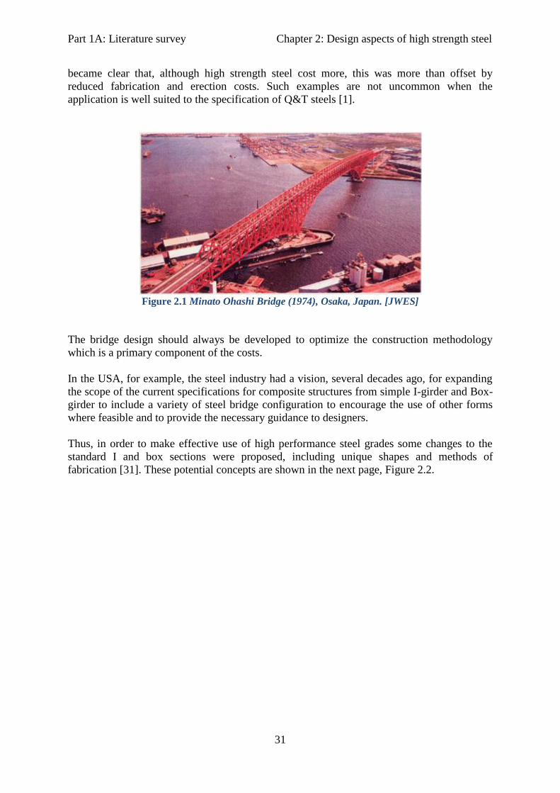
Part 1A: Literature survey Chapter 2: Design aspects of high strength steel
31
became clear that, although high strength steel cost more, this was more than offset by
reduced fabrication and erection costs. Such examples are not uncommon when the
application is well suited to the specification of Q&T steels [1].
Figure 2.1 Minato Ohashi Bridge (1974), Osaka, Japan. [JWES]
The bridge design should always be developed to optimize the construction methodology
which is a primary component of the costs.
In the USA, for example, the steel industry had a vision, several decades ago, for expanding
the scope of the current specifications for composite structures from simple I-girder and Box-
girder to include a variety of steel bridge configuration to encourage the use of other forms
where feasible and to provide the necessary guidance to designers.
Thus, in order to make effective use of high performance steel grades some changes to the
standard I and box sections were proposed, including unique shapes and methods of
fabrication [31]. These potential concepts are shown in the next page, Figure 2.2.
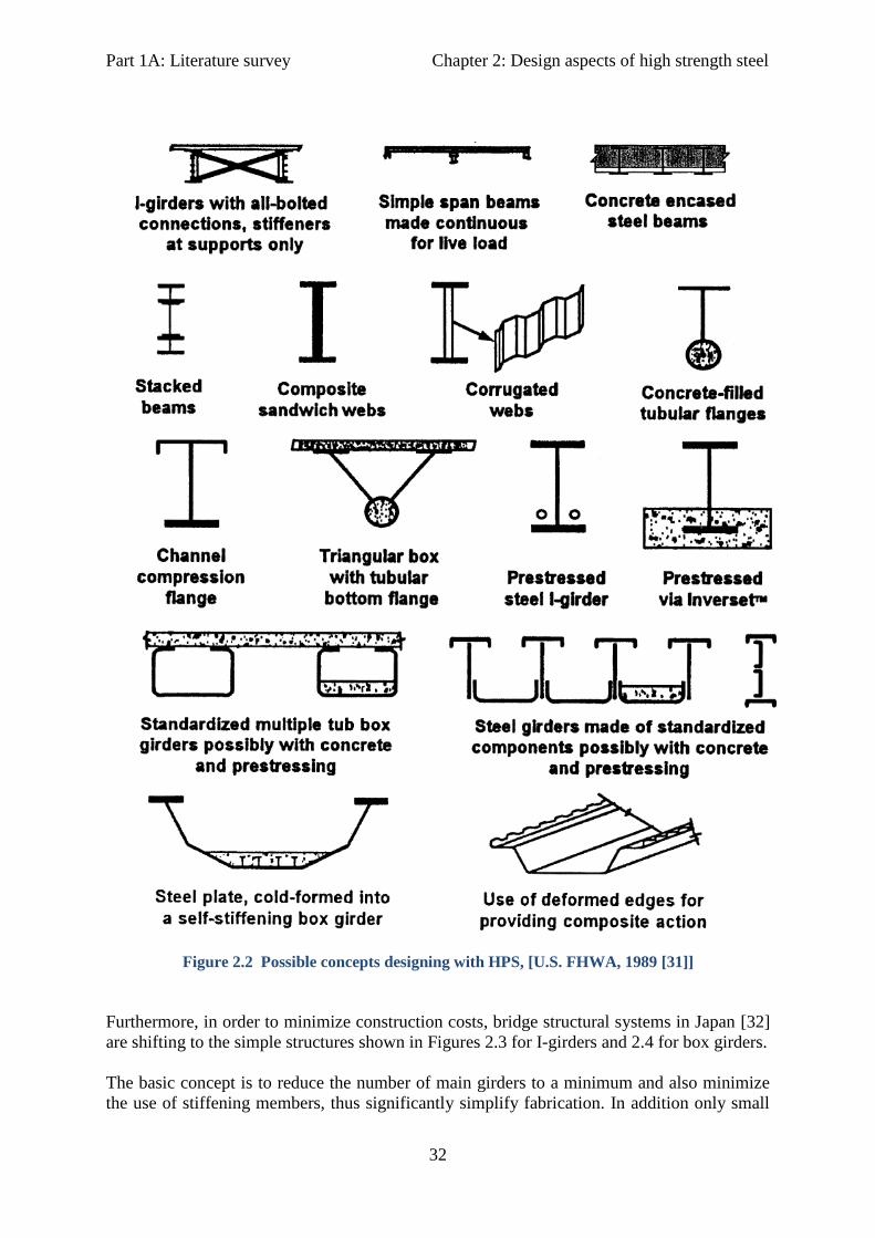
Part 1A: Literature survey Chapter 2: Design aspects of high strength steel
32
Figure 2.2 Possible concepts designing with HPS, [U.S. FHWA, 1989 [31]]
Furthermore, in order to minimize construction costs, bridge structural systems in Japan [32]
are shifting to the simple structures shown in Figures 2.3 for I-girders and 2.4 for box girders.
The basic concept is to reduce the number of main girders to a minimum and also minimize
the use of stiffening members, thus significantly simplify fabrication. In addition only small

Part 1A: Literature survey Chapter 2: Design aspects of high strength steel
33
sized cross beams are arranged between the main girders and the use of lower lateral bracing
is eliminated.
Figure 2.3 Structural innovations for I-girders (Dr. M. Nagai, 2006) [32].
Figure 2.4 Structural innovations for Box girders (Dr. M. Nagai, 2006) [32].
These types of construction are economical for span ranges between 30-60 m as shown in
table 2.1.
For small spans (<30 m) and for spans longer than 60-70 m concrete bridges are more
economical. A steel alternative expected to be very competitive in the range of 70-120 m, is
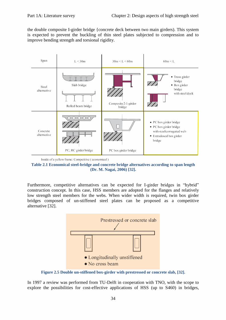
Part 1A: Literature survey Chapter 2: Design aspects of high strength steel
34
the double composite I-girder bridge {concrete deck between two main girders). This system
is expected to prevent the buckling of thin steel plates subjected to compression and to
improve bending strength and torsional rigidity.
Table 2.1 Economical steel-bridge and concrete bridge alternatives according to span length
(Dr. M. Nagai, 2006) [32].
Furthermore, competitive alternatives can be expected for I-girder bridges in “hybrid”
construction concept. In this case, HSS members are adopted for the flanges and relatively
low strength steel members for the webs. When wider width is required, twin box girder
bridges composed of un-stiffened steel plates can be proposed as a competitive
alternative [32].
Figure 2.5 Double un-stiffened box-girder with prestressed or concrete slab, [32].
In 1997 a review was performed from TU-Delft in cooperation with TNO, with the scope to
explore the possibilities for cost-effective applications of HSS (up to S460) in bridges,

Part 1A: Literature survey Chapter 2: Design aspects of high strength steel
35
buildings, cranes etc. [34]. According to this review HSS is especially cost effective in
situations where the weight of the structure forms an important part of the load e.g. long span
bridges, high rise buildings and cranes.
HSS may be more expensive to purchase, however, in the fabrication welding is the most
costly. HSS have good ductility and weldability which has a favourable effect on mechanical
behaviour of the structures and will reduce the fabrication costs significantly. Furthermore, it
was concluded that new design rules help design more economically in high strength steel.
Today EN 1993-1-12 serves this scope so far in addition to testing and experimental research.
Table 2.2 Example of plated structure - Data cost savings, [Dillinger Hütte].
In addition, some general guidelines were given depending on the type of the loading that are
summarized here:
Members in tension: If tension governs the design, a choice of S460 instead of S355 gives a
material saving of 30%. If for example, S460 is considered 20% more expensive, then the
overall cost savings will be 10% but on top of that the savings in fabrication costs are much
greater.
Stiffness: Where deflection criteria govern (SLS), HSS is not favourable with the current
design rules. This is so because higher stresses with the same E-modulus will cause bigger
deflections. It could be possible, however, that SLS limits for deflections could be somewhat
relaxed in some cases to allow for a more effective use of HSS. New design rules need to be
developed for that.
Members in bending: Application of HSS may have a big influence on the design choice. A
cost effective choice in that case is the hybrid construction, where the webs on the welded
girders are made from lower steel grades (e.g. S355) and the flanges of HSS (e.g. S690). This
is so, because the web plates usually, have to be design to satisfy instability criteria. In that
case working stresses are lower due to buckling and a higher grade is not effective.
Members in Compression: Here buckling phenomena govern the design which is based on
E-modulus. This is the same for all steel grades, but if slenderness is low λ< 60-80, then the
weight savings will still be obtained. Furthermore, sections in HSS have relatively lower
residual stresses than sections in S355 or in S235. Therefore, design codes
(EN 1993 National Annex D) give for example, a better buckling curve for steels S420-S460.
Generally, Table 6.2 for choosing the buckling curve in EN 1993-1-1:2005, holds also for
steel grades up to S700 (EN 1993-1-12:2007).
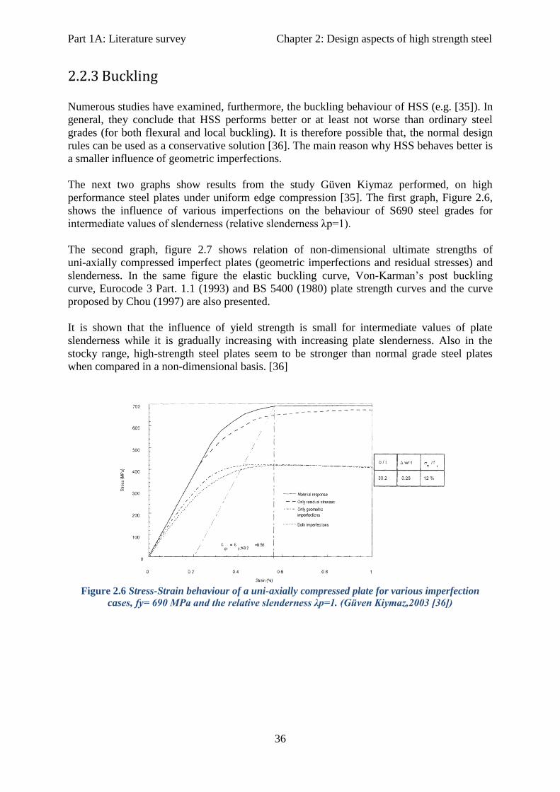
Part 1A: Literature survey Chapter 2: Design aspects of high strength steel
36
2.2.3 Buckling
Numerous studies have examined, furthermore, the buckling behaviour of HSS (e.g. [35]). In
general, they conclude that HSS performs better or at least not worse than ordinary steel
grades (for both flexural and local buckling). It is therefore possible that, the normal design
rules can be used as a conservative solution [36]. The main reason why HSS behaves better is
a smaller influence of geometric imperfections.
The next two graphs show results from the study Güven Kiymaz performed, on high
performance steel plates under uniform edge compression [35]. The first graph, Figure 2.6,
shows the influence of various imperfections on the behaviour of S690 steel grades for
intermediate values of slenderness (relative slenderness λp=1).
The second graph, figure 2.7 shows relation of non-dimensional ultimate strengths of
uni-axially compressed imperfect plates (geometric imperfections and residual stresses) and
slenderness. In the same figure the elastic buckling curve, Von-Karman’s post buckling
curve, Eurocode 3 Part. 1.1 (1993) and BS 5400 (1980) plate strength curves and the curve
proposed by Chou (1997) are also presented.
It is shown that the influence of yield strength is small for intermediate values of plate
slenderness while it is gradually increasing with increasing plate slenderness. Also in the
stocky range, high-strength steel plates seem to be stronger than normal grade steel plates
when compared in a non-dimensional basis. [36]
Figure 2.6 Stress-Strain behaviour of a uni-axially compressed plate for various imperfection
cases, fy= 690 MPa and the relative slenderness λp=1. (Güven Kiymaz,2003 [36])

Part 1A: Literature survey Chapter 2: Design aspects of high strength steel
37
Figure 2.7 Non-dimensional strength of uni-axially compressed imperfect plates with various
yield strengths over a range of plate slenderness. (Güven Kiymaz, 2003 [36])
2.2.4 Fatigue
The graph in Figure 2.8 shows that fatigue strength increases with tensile strength for plane
materials, but in welded and notched details fatigue strength is independent of increasing
yield strength. This is why the application of high strength steel in fatigue loaded structures
with a high number of stress cycles during their lifetime, such as bridges, is still questionable.
Experimental research though, based on fatigue data for parent and welded high strength
steels, indicates that the general performance of high strength steels is as good as the medium
strength steels.
Figure 2.8 Fatigue strength in relation to material yield strength [37].
Gurney (1979) concluded that the higher the yield strength of base materials the more
sensitive the fatigue strength of the material becomes to both the presence of notches and to

Part 1A: Literature survey Chapter 2: Design aspects of high strength steel
38
the surface condition. In case of low notch values notch sensitivity of fatigue strength is
minimized. Therefore the use of high strength steel in welded connections requires high
fabrication quality and avoidance of large stress concentrations in joints [38]
2.2.4.1 FATIGUE OF WELDED DETAILS
It is well known that welded details determine the fatigue behaviour in a welded structure.
This was also shown in Figure 2.8. Therefore, several conditions need to be fulfilled for
making use of the HSS in fatigue loaded structures in an effective way. Welded details should
be at the least severe loaded locations in the structure, wherever possible.
It is also important to ensure high quality details with good surface finishing minimizing
defects, so that large stress concentrations at these locations are avoided. Removing overfills
in welded joints, for example, can improve the fatigue behaviour of the joint, although it will
remain lower than that of the parent metal [39]. However, in cases of high overloads high
strength steels can be more beneficial than regular grades, since it allows for higher stress
levels.
Puthli et al. (2006) examined the fatigue strength of longitudinal attachments welded to plates
and tubes made of high strength steels S460, S690, S960 and S1100. They showed that high
strength steels do not exhibit any disadvantage in fatigue resistance compared to mild steels.
EN 1993-1-9 (2005) indicates that the fatigue strength of the steel structure depends on the
applied detail (notch factor), plate thickness and machining condition. This standard is
generally applicable also to high strength steels covered by EN 1993-1-12 (2007).
Furthermore, fatigue performance of welded details is strongly dependent on the initiation of
a crack, usually located at the weld toe or at the weld root, followed by crack propagation.
The number of cycles required to initiate a crack depends on applied stress, weld geometry
and material properties. Crack nucleation at the weld joint is related to the fatigue strength of
the base material because the presence of the welded joint acts as a notch [40].
Since fatigue crack propagation characteristics are the same for low and high strength
structural steels an effective way to improve the fatigue resistance of welded details in HSS,
would be to introduce a longer initiation period [41]. This can be achieved in two ways. An
improved weld procedure which will give smaller global and local stress concentrations and a
global post weld improvement technique (e.g. post weld shot peening).
The strength of the weld metal in relation to the strength of the base metal is particularly
important for the behaviour of a welded joint. In normal steel grades the weld metal is always
stronger than the base metal (over matched welds) in order to achieve a more ductile
behaviour of the welded connection and therefore enhance the safety of the structure.
When HSS (above S690) is used, however, the weld metal will be weaker than the base metal
(under matched welds). When such joints are loaded up to failure, large strains will occur in
the welds and not in the adjacent parent metal. Due to small dimensions of the weld the
deformation capacity of these connections can be limited and potential stress redistribution
will also be limited (the weld will fail before the load is redistributed). So special attention
should be paid when under matched welds are used with respect to deformation capacity and
the SCFs (stress concentration factor resulting from unequal stress/strain distribution, which
in case of under- matched welds will be concentrated In the weld itself).
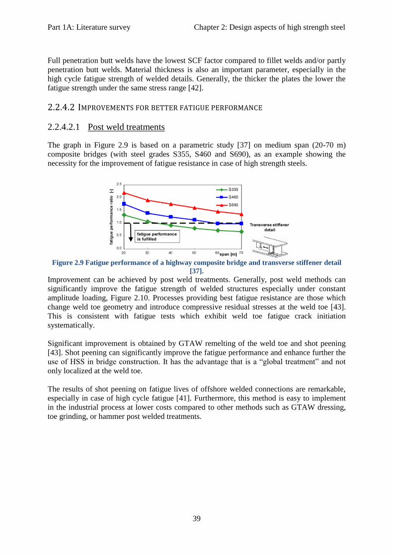
Part 1A: Literature survey Chapter 2: Design aspects of high strength steel
39
Full penetration butt welds have the lowest SCF factor compared to fillet welds and/or partly
penetration butt welds. Material thickness is also an important parameter, especially in the
high cycle fatigue strength of welded details. Generally, the thicker the plates the lower the
fatigue strength under the same stress range [42].
2.2.4.2 IMPROVEMENTS FOR BETTER FATIGUE PERFORMANCE
2.2.4.2.1 Post weld treatments
The graph in Figure 2.9 is based on a parametric study [37] on medium span (20-70 m)
composite bridges (with steel grades S355, S460 and S690), as an example showing the
necessity for the improvement of fatigue resistance in case of high strength steels.
Figure 2.9 Fatigue performance of a highway composite bridge and transverse stiffener detail
[37].
Improvement can be achieved by post weld treatments. Generally, post weld methods can
significantly improve the fatigue strength of welded structures especially under constant
amplitude loading, Figure 2.10. Processes providing best fatigue resistance are those which
change weld toe geometry and introduce compressive residual stresses at the weld toe [43].
This is consistent with fatigue tests which exhibit weld toe fatigue crack initiation
systematically.
Significant improvement is obtained by GTAW remelting of the weld toe and shot peening
[43]. Shot peening can significantly improve the fatigue performance and enhance further the
use of HSS in bridge construction. It has the advantage that is a “global treatment” and not
only localized at the weld toe.
The results of shot peening on fatigue lives of offshore welded connections are remarkable,
especially in case of high cycle fatigue [41]. Furthermore, this method is easy to implement
in the industrial process at lower costs compared to other methods such as GTAW dressing,
toe grinding, or hammer post welded treatments.

Part 1A: Literature survey Chapter 2: Design aspects of high strength steel
40
Figure 2.10 Improvement techniques for fatigue performance [43].
The international institute of welding (IIW) gives recommendations with regard to post weld
improvements of arc welded steel structures [63]. Four methods are described namely, burr
grinding, tig dressing, hammer peening and needle peening. The benefits from all these
methods are higher for steels with specified yield stress above 350 MPa in comparison to
lower steel grades (i.e. for steels with specified yield stress above 350 MPa a factor of 1.5 on
allowable stress range can be considered, limited to an increase to FAT 100). The higher
fatigue category that can benefit from these treatments is FAT 90 (fatigue strength at
2 million cycles).
2.2.4.2.2 Cast joints
A very efficient way of reducing stress concentrations on welded details is to position them
away from the critical, highly stressed, locations on the structure. Cast joints, if designed
properly, successfully provide this benefit.
Cast steel is available up to 1100 MPa yield strength and is more and more applied in fatigue
loaded bridge and offshore structures. A hybrid connection of cast steel welded to a rolled
steel member could make the use of high strength steels relatively more efficient.
A very efficient and promising application of HSS is in stiff truss like structures, typically
made of circular hollow sections (CHS). Use of castings in combination with CHS could be
promising for the design of highly resistant fatigue joints [38].
In 2009 an experimental program was performed in TU-Delft University of Technology, in
order to investigate the fatigue strength of hybrid connections made of rolled and cast steel
with high yield strength [38]. The experimental program included two parts: Large scale test
series on trusses made of welded CHS and K-joint cast members (Figure 2.11) and small
scale test series on V-welded plate connections made of rolled and cast steel (Figure 2.12).
Strengths for rolled and cast steels were 690 MPa and 890 MPa, while for the small scale
tests also S460 steel was tested.

Part 1A: Literature survey Chapter 2: Design aspects of high strength steel
41
Results show, that fatigue class 71 in the Eurocodes, is rather conservative. Most cracks seem
to initiate at the HAZ next to the weld locations, while the use of ceramic backing is found
not to improve the fatigue performance. Instead, the steeper weld root angle of the specimens
welded with use of ceramic backing resulted in lower fatigue strength. Furthermore the
results on steels S690 and S890, showed slightly higher fatigue strength (although, the
number of test specimens was quite low to evaluate the influence of the yield strength).
Figure 2.11 Conceptual drawing of large scale setup for CHS trusses with VHSS K-joint cast
steel members [38].
Figure 2.12 Geometry of small scale V-welded plates from rolled (S460, S690 and S890) and cast
(G20Mn5, G10MNMoV6-3 and G18NiMoCr3-6) steel [38].
Finally, economic efficiency of cast steel joints depends largely on the manufacturing of the
formwork. High cost effectiveness can be achieved if the bridge design allows a large number
of equal joints.
2.2.4.2.3 Transverse Butt welds
Fatigue performance of welded structures can be improved significantly with optimized
design of welded details and high quality welding techniques. In the codes, several welded
details are classified in categories according to their fatigue strength (Δσ value, usually at
2 million cycles). From these, the transverse butt weld detail appears to have low stress
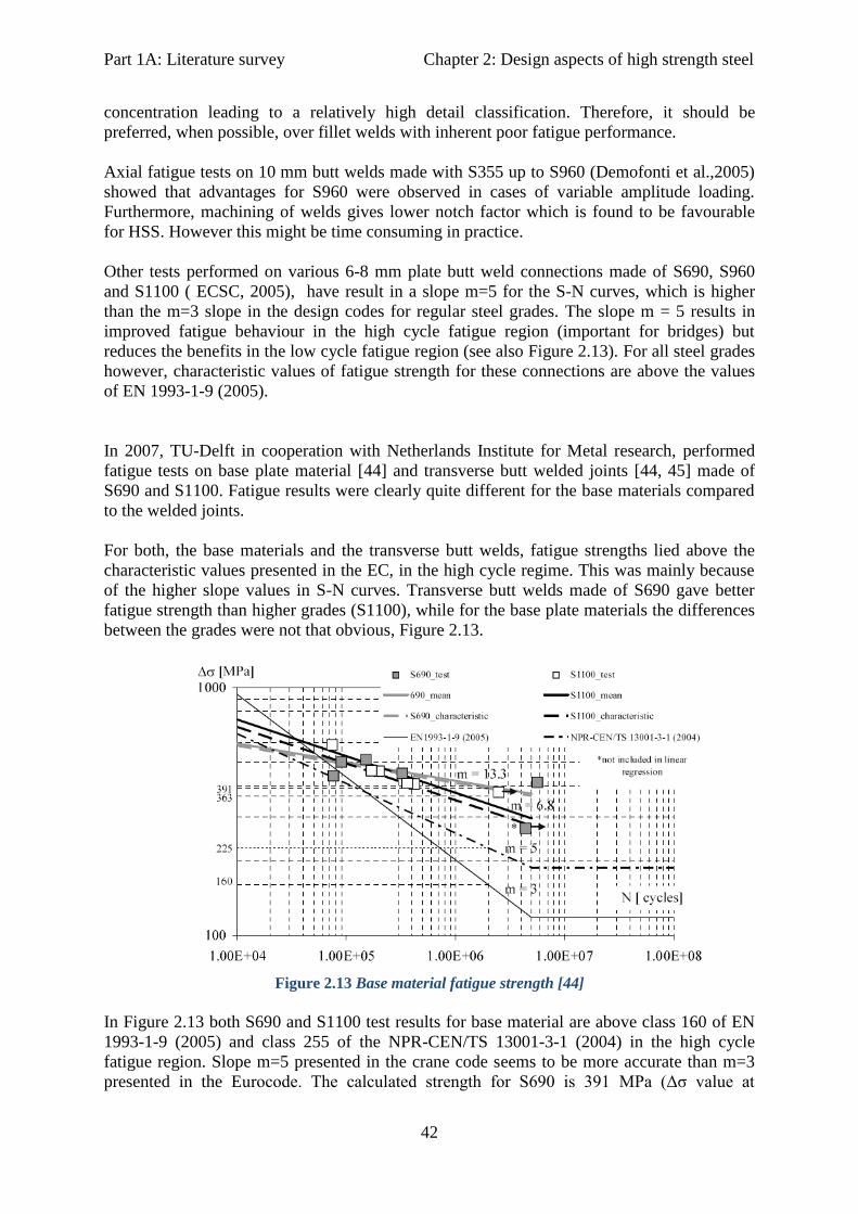
Part 1A: Literature survey Chapter 2: Design aspects of high strength steel
42
concentration leading to a relatively high detail classification. Therefore, it should be
preferred, when possible, over fillet welds with inherent poor fatigue performance.
Axial fatigue tests on 10 mm butt welds made with S355 up to S960 (Demofonti et al.,2005)
showed that advantages for S960 were observed in cases of variable amplitude loading.
Furthermore, machining of welds gives lower notch factor which is found to be favourable
for HSS. However this might be time consuming in practice.
Other tests performed on various 6-8 mm plate butt weld connections made of S690, S960
and S1100 ( ECSC, 2005), have result in a slope m=5 for the S-N curves, which is higher
than the m=3 slope in the design codes for regular steel grades. The slope m = 5 results in
improved fatigue behaviour in the high cycle fatigue region (important for bridges) but
reduces the benefits in the low cycle fatigue region (see also Figure 2.13). For all steel grades
however, characteristic values of fatigue strength for these connections are above the values
of EN 1993-1-9 (2005).
In 2007, TU-Delft in cooperation with Netherlands Institute for Metal research, performed
fatigue tests on base plate material [44] and transverse butt welded joints [44, 45] made of
S690 and S1100. Fatigue results were clearly quite different for the base materials compared
to the welded joints.
For both, the base materials and the transverse butt welds, fatigue strengths lied above the
characteristic values presented in the EC, in the high cycle regime. This was mainly because
of the higher slope values in S-N curves. Transverse butt welds made of S690 gave better
fatigue strength than higher grades (S1100), while for the base plate materials the differences
between the grades were not that obvious, Figure 2.13.
Figure 2.13 Base material fatigue strength [44]
In Figure 2.13 both S690 and S1100 test results for base material are above class 160 of EN
1993-1-9 (2005) and class 255 of the NPR-CEN/TS 13001-3-1 (2004) in the high cycle
fatigue region. Slope m=5 presented in the crane code seems to be more accurate than m=3
presented in the Eurocode. The calculated strength for S690 is 391 MPa (Δσ value at

Part 1A: Literature survey Chapter 2: Design aspects of high strength steel
43
2 million cycles), much higher than the 339 MPa value for S1100. Thus it is obvious that
higher yield strength leads to higher fatigue strength also for base material.
Figure 2.14 Transverse butt welds fatigue results [44]
The behaviour of transverse butt welds however is different as shown in Figure 2.14. The
calculated strength for S690 was 92 MPa, which is in good correspondence with a high
quality butt weld of regular steel (class 90 of EN 1993-1-9 (2005)), but lower than class 140
of NPR CEN/TS 13001-3-1 (2004). Plus, the slope of S-N curves (m=2.8) is lower than the
slope value m=3 according to both codes.
On the other hand S1100 butt welds show a complete different behaviour than S690. The
slope is higher m=5.7 and the strength is 180 MPa which is a higher value compared to both
codes. The results are summarized in Table 2.3.
Table 2.3 Fatigue strength comparison (N= 2*10^6 cycles) [44]
Additionally, as a part of the same PhD programme at TU-Delft, for the applicability of
VHSS in civil engineering structures, transverse butt welds (S690 and S1100) were tested
with respect to fatigue [45]. Results from tensile tests on these specimens showed a brittle
failure since the yield to tensile strength ratio is low compared to regular steels (especially for
S1100).
However, research also showed that the higher tensile strength of S1100 transverse butt welds
gives higher fatigue strength and that the fatigue strength of S690 butt welded joints lied well
above the design value in EN 1993-1-9 code.
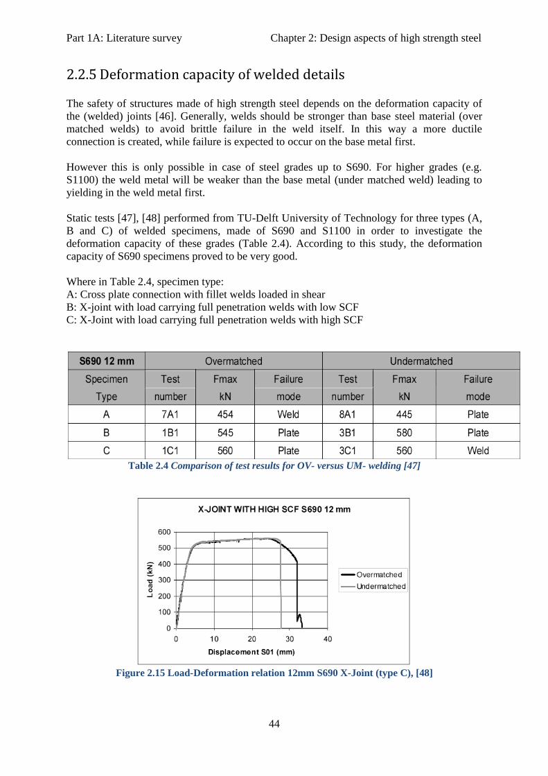
Part 1A: Literature survey Chapter 2: Design aspects of high strength steel
44
2.2.5 Deformation capacity of welded details
The safety of structures made of high strength steel depends on the deformation capacity of
the (welded) joints [46]. Generally, welds should be stronger than base steel material (over
matched welds) to avoid brittle failure in the weld itself. In this way a more ductile
connection is created, while failure is expected to occur on the base metal first.
However this is only possible in case of steel grades up to S690. For higher grades (e.g.
S1100) the weld metal will be weaker than the base metal (under matched weld) leading to
yielding in the weld metal first.
Static tests [47], [48] performed from TU-Delft University of Technology for three types (A,
B and C) of welded specimens, made of S690 and S1100 in order to investigate the
deformation capacity of these grades (Table 2.4). According to this study, the deformation
capacity of S690 specimens proved to be very good.
Where in Table 2.4, specimen type:
A: Cross plate connection with fillet welds loaded in shear
B: X-joint with load carrying full penetration welds with low SCF
C: X-Joint with load carrying full penetration welds with high SCF
Table 2.4 Comparison of test results for OV- versus UM- welding [47]
Figure 2.15 Load-Deformation relation 12mm S690 X-Joint (type C), [48]
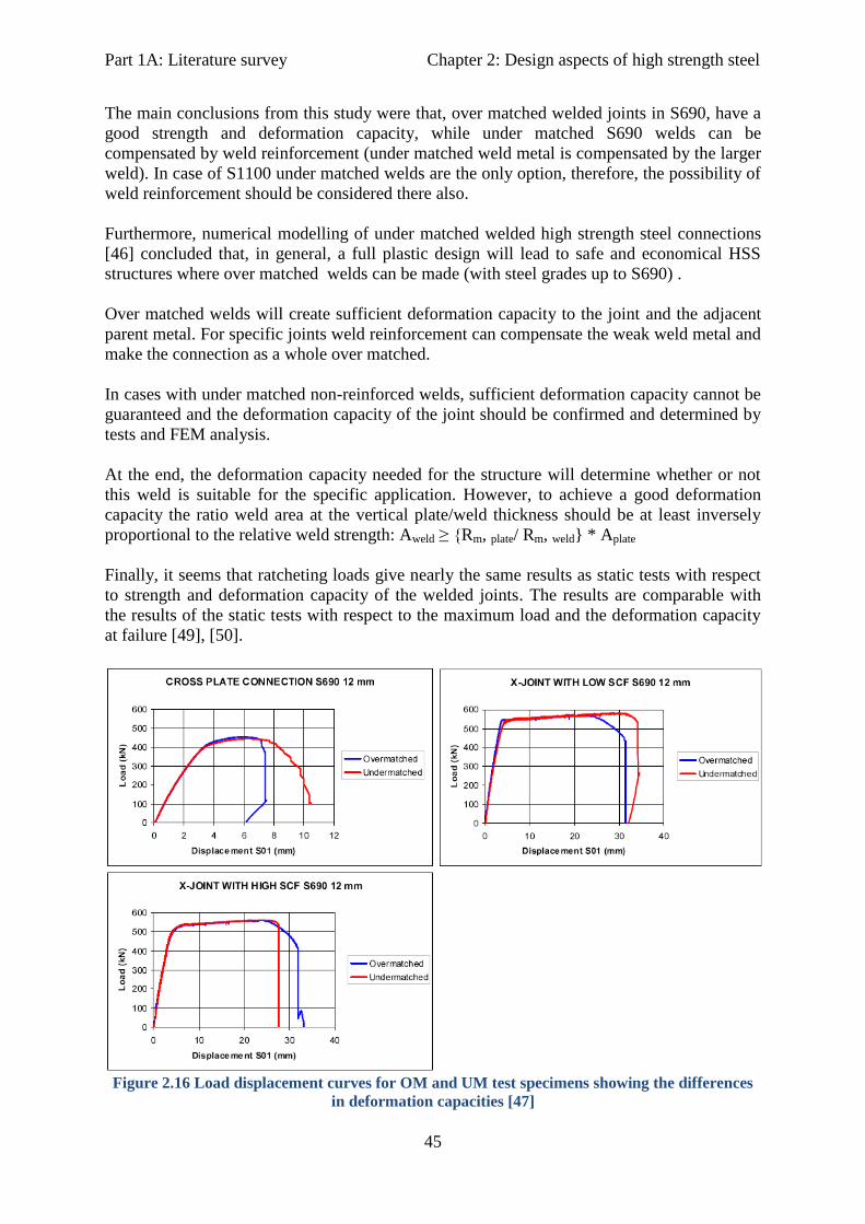
Part 1A: Literature survey Chapter 2: Design aspects of high strength steel
45
The main conclusions from this study were that, over matched welded joints in S690, have a
good strength and deformation capacity, while under matched S690 welds can be
compensated by weld reinforcement (under matched weld metal is compensated by the larger
weld). In case of S1100 under matched welds are the only option, therefore, the possibility of
weld reinforcement should be considered there also.
Furthermore, numerical modelling of under matched welded high strength steel connections
[46] concluded that, in general, a full plastic design will lead to safe and economical HSS
structures where over matched welds can be made (with steel grades up to S690) .
Over matched welds will create sufficient deformation capacity to the joint and the adjacent
parent metal. For specific joints weld reinforcement can compensate the weak weld metal and
make the connection as a whole over matched.
In cases with under matched non-reinforced welds, sufficient deformation capacity cannot be
guaranteed and the deformation capacity of the joint should be confirmed and determined by
tests and FEM analysis.
At the end, the deformation capacity needed for the structure will determine whether or not
this weld is suitable for the specific application. However, to achieve a good deformation
capacity the ratio weld area at the vertical plate/weld thickness should be at least inversely
proportional to the relative weld strength: Aweld ≥ {Rm, plate/ Rm, weld} * Aplate
Finally, it seems that ratcheting loads give nearly the same results as static tests with respect
to strength and deformation capacity of the welded joints. The results are comparable with
the results of the static tests with respect to the maximum load and the deformation capacity
at failure [49], [50].
Figure 2.16 Load displacement curves for OM and UM test specimens showing the differences
in deformation capacities [47]

Part 1A: Literature survey Chapter 2: Design aspects of high strength steel
46
2.3 Economic and other benefits of using HSS for bridge design
The advantages of using high strength steels are generally a result of reduced weight and
dimensions. Design stresses can be increased and plate thickness may be reduced, resulting in
significant weight savings. Reduced plate thickness can also save on welding costs as it leads
to smaller weld volumes. Simplified structural components and construction techniques are
often possible, particularly for large structures, and foundation costs may also be reduced due
to lower dead weight.
The most economical and efficient use of high strength steel for bridge design, is
Q&T steels in members stressed in tension where the high strength can be fully exploited,
and in projects where the dead weight of the steel is the predominant load, such as in long
span bridges. In compression they are most effective in heavily loaded, stocky columns or in
stiffened compression elements where buckling is not the controlling criterion.
Usually, the cost of the material increases as the strength increases (Figure 2.17, left).
However, when the higher strength can be fully utilized then the relative material cost is
reduced (Figure 2.17 right) [36].
In that respect, a very cost-effective solution is “hybrid girders”. These are girders with
flanges of HSS and web of lower steel grade, which are proved to be more economical than
homogeneous girders. It is suggested that the strength of the flanges should not exceed twice
that of the web for serviceability reasons.
For economy in fabrication, rules require matching electrodes which this requirement can be
met with HSS up to S690 [51]. These grades are commonly used in US and in Japan for
many years, while in Europe their use is still limited.
Figure 2.17 Left: Approximate price per tonne of hot rolled steel, normalized with price of S235
as function of yield strength. Right: Approximate material costs normalized with the cost of 235
assuming that the strength can be fully utilized [36].
In U.S. many research activities are focused on exploring the benefits of HSS bridges over
concrete bridges and making steel bridge construction more cost-effective. Most of them
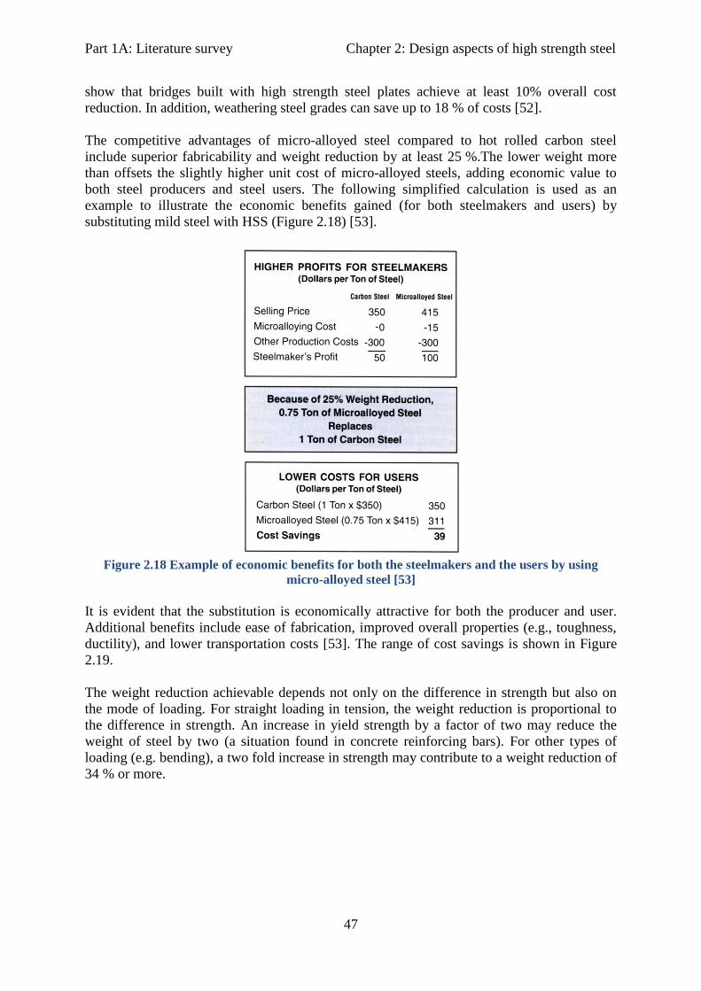
Part 1A: Literature survey Chapter 2: Design aspects of high strength steel
47
show that bridges built with high strength steel plates achieve at least 10% overall cost
reduction. In addition, weathering steel grades can save up to 18 % of costs [52].
The competitive advantages of micro-alloyed steel compared to hot rolled carbon steel
include superior fabricability and weight reduction by at least 25 %.The lower weight more
than offsets the slightly higher unit cost of micro-alloyed steels, adding economic value to
both steel producers and steel users. The following simplified calculation is used as an
example to illustrate the economic benefits gained (for both steelmakers and users) by
substituting mild steel with HSS (Figure 2.18) [53].
Figure 2.18 Example of economic benefits for both the steelmakers and the users by using
micro-alloyed steel [53]
It is evident that the substitution is economically attractive for both the producer and user.
Additional benefits include ease of fabrication, improved overall properties (e.g., toughness,
ductility), and lower transportation costs [53]. The range of cost savings is shown in Figure
2.19.
The weight reduction achievable depends not only on the difference in strength but also on
the mode of loading. For straight loading in tension, the weight reduction is proportional to
the difference in strength. An increase in yield strength by a factor of two may reduce the
weight of steel by two (a situation found in concrete reinforcing bars). For other types of
loading (e.g. bending), a two fold increase in strength may contribute to a weight reduction of
34 % or more.

Part 1A: Literature survey Chapter 2: Design aspects of high strength steel
48
Figure 2.19 Cost savings by the use of HSS [SSAB Sheet Steel Handbook]
However, in case that buckling governs the saving in material costs will be slightly smaller
and will depend on the type of buckling and the slenderness of the component.
Figure 2.20 Left: Relative material cost for column subject to flexural buckling as a function to
yield strength. Reference costs are for S235. Right: relative costs for a plate supported along all
four edges, subject to uniform compression as a function of yield strength. Reference costs are
for S235 [36].
Figure 2.20 (left) shows that you save money with increasing strength in case of stocky
columns (I/i= 40). For I/i= 60 we gain minimum costs for yield strength 600 MPa.
In Figure 2.20 (right) the plate slenderness is represented by the width over thickness ratio
(b/t). It is obvious that increasing the yield strength always reduces the material costs but for
slender plates the savings are quite small. Therefore the plate slenderness has to be kept low
in order to obtain substantial cost savings.
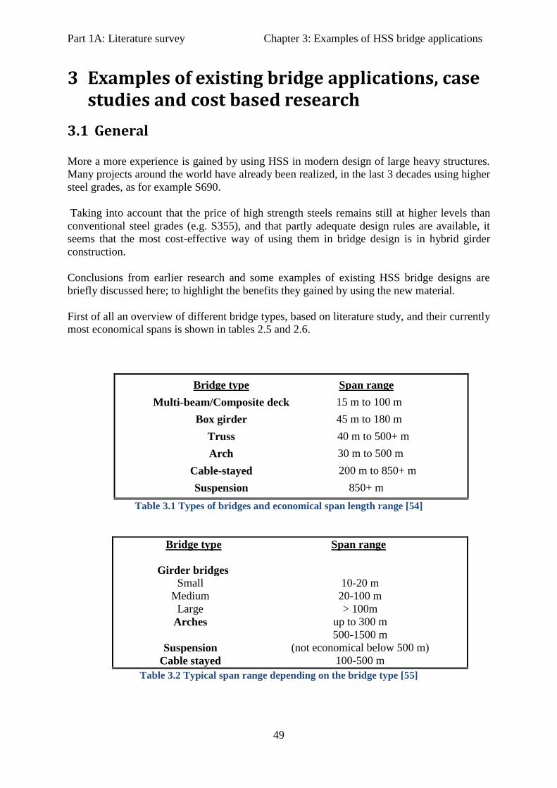
Part 1A: Literature survey Chapter 3: Examples of HSS bridge applications
49
3 Examples of existing bridge applications, case studies and cost based research
3.1 General
More a more experience is gained by using HSS in modern design of large heavy structures.
Many projects around the world have already been realized, in the last 3 decades using higher
steel grades, as for example S690.
Taking into account that the price of high strength steels remains still at higher levels than
conventional steel grades (e.g. S355), and that partly adequate design rules are available, it
seems that the most cost-effective way of using them in bridge design is in hybrid girder
construction.
Conclusions from earlier research and some examples of existing HSS bridge designs are
briefly discussed here; to highlight the benefits they gained by using the new material.
First of all an overview of different bridge types, based on literature study, and their currently
most economical spans is shown in tables 2.5 and 2.6.
Bridge type Span range
Multi-beam/Composite deck 15 m to 100 m
Box girder 45 m to 180 m
Truss 40 m to 500+ m
Arch 30 m to 500 m
Cable-stayed 200 m to 850+ m
Suspension 850+ m
Table 3.1 Types of bridges and economical span length range [54]
Bridge type Span range
Girder bridges
Small 10-20 m
Medium 20-100 m
Large > 100m
Arches up to 300 m
Suspension
500-1500 m
(not economical below 500 m)
Cable stayed 100-500 m
Table 3.2 Typical span range depending on the bridge type [55]

Part 1A: Literature survey Chapter 3: Examples of HSS bridge applications
50
Table 3.3 Availability of steel plates for different bridge types, [56]
3.2 Examples in Europe
3.2.1 The Prince Clause Bridge, the Netherlands
This cable-stayed bridge (fig.19) which opened in June 2003 spans the Amsterdam Rhine
canal between the Kanaleneiland and the new Papendorp business quarter. It has a total
length of 300m (150 m cable stayed span) and 35m width and carries regional tramway rail
routes, road traffic, cyclists and pedestrians. High strength structural steel S460, in
thicknesses 20-100mm, was used for the heavily stressed pylon elements [57].
Figure 3.1 The Prince Clause bridge, Utrecht.

Part 1A: Literature survey Chapter 3: Examples of HSS bridge applications
51
3.2.2 Bridge HST over the Hollandsch Diep
[57] This is a new high speed railway bridge, located between Dordrecht and Breda, over
Hollansch Diep (1200 m wide). The steel structure consists of hammer-head-shaped elements
above the piers with connected box girder sections. Plates of S460N and S355J2G3,
100- 210 mm thick were supplied for this structure. Exceptionally broad plates of 4,550 mm
where prefabricated and transferred on site by ship and lifted into position with a 500 t
floating crane, permitting minimization of costly and complex on site welding.
Figure 3.2 Bridge HST, Hollandsch Diep 1998-2006
3.2.3 The Ennëus Heerma bridge
[57] It is an unusual shaped bow string bridge of 230 m length, 38 m width and 26 m height
(four motor traffic carriageways, two tram lines, two cycle tracks and a pedestrian walkway.
It was completed in 2001. TM-rolled fine grain steel of minimum yield strength 460 MPa in
thickness up to 100 mm were used for the cross members of the composite carriageway deck
and the central arches in order to safely absorb the high stresses occurring at these zones of
the bridge.
Figure 3.3 The Ennëus Heerma bridge, The Netherlands [Wikipedia].

Part 1A: Literature survey Chapter 3: Examples of HSS bridge applications
52
3.2.4 Fast Bridge 48 Military Bridge, Sweden [Höglund]
The bridge was designed and constructed only for military purposes. The main features
include:
Geometry: span 32-48 m with 4-6.8 m long (truss girder) sections, 4 m wide and 1.6 m deep.
System: 2 truss girder single-span bridge with VHSS deck (S1100, 5mm thick), stiffened by
cold formed steel channel sections with web folds. The bottom chord is made of cold formed
sections whereas the diagonals in the truss are made of S460 rectangular hollow sections. The
coupling plates are made of 50 mm S960 plates.
The fast bridge 48 required steel with 1100 MPa yield strength and impact toughness 40 J
in 40 ºC. Due to the fact that these grades were not covered by the national standards
extensive testing on buckling and fatigue behaviour was carried out to verify the structural
integrity of all components. However there are no limitations on the deflections for Military
bridges.
Figure 3.4 Cross section of Fast bridge 48.
As there are no limitations on deflections for military bridges, the strength of very high
strength steel could fully utilize. The result is a light-weight bridge competitive to aluminium
alloys and polymers. Furthermore, reduced fabrication costs and extended service life added
more positive value to the specific design. With further development this design can reach up
to 200 m span length, with intermediate supports dropped from the bridge during launching.
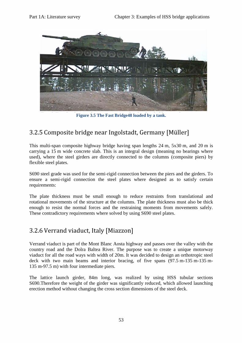
Part 1A: Literature survey Chapter 3: Examples of HSS bridge applications
53
Figure 3.5 The Fast Bridge48 loaded by a tank.
3.2.5 Composite bridge near Ingolstadt, Germany [Müller]
This multi-span composite highway bridge having span lengths 24 m, 5x30 m, and 20 m is
carrying a 15 m wide concrete slab. This is an integral design (meaning no bearings where
used), where the steel girders are directly connected to the columns (composite piers) by
flexible steel plates.
S690 steel grade was used for the semi-rigid connection between the piers and the girders. To
ensure a semi-rigid connection the steel plates where designed as to satisfy certain
requirements:
The plate thickness must be small enough to reduce restraints from translational and
rotational movements of the structure at the columns. The plate thickness must also be thick
enough to resist the normal forces and the restraining moments from movements safely.
These contradictory requirements where solved by using S690 steel plates.
3.2.6 Verrand viaduct, Italy [Miazzon]
Verrand viaduct is part of the Mont Blanc Aosta highway and passes over the valley with the
country road and the Dolra Baltea River. The purpose was to create a unique motorway
viaduct for all the road ways with width of 20m. It was decided to design an orthotropic steel
deck with two main beams and interior bracing, of five spans (97.5 m-135 m-135 m-
135 m-97.5 m) with four intermediate piers.
The lattice launch girder, 84m long, was realized by using HSS tubular sections
S690.Therefore the weight of the girder was significantly reduced, which allowed launching
erection method without changing the cross section dimensions of the steel deck.

Part 1A: Literature survey Chapter 3: Examples of HSS bridge applications
54
3.2.7 Sweden, Hybrid Girder Bridge
In Sweden is a common practice to mix different steel grades for a single cross section, with
the stronger grade at the flanges and the weaker in the webs. These types of girders (hybrid
girders), are standardized in Swedish codes. It is required that the flange strength may not
exceed 50 % of the web strength. Furthermore, when the design is reduced with respect to
buckling of normal stresses, the effective web thickness is based on the strength of the flange
and not the web itself.
In 1995, a single span bridge was erected in Mttådalen with a span of 20 m and free width
7 m. For the lower flanges S690 steel was used, while for the upper flange and the web S460
steel grade was used. Using S690 also for the upper flange proved not to be cost effective,
since it is often submitted to buckling and/or lateral torsional buckling during erection and
casting.
Three alternative designs were made with respect to different material combinations: S355 all
over the cross section; S460 only at the bottom flange and to the right; S460 in the web and
top flange and S690 for the bottom flange. A comparison based n costs of the three designs is
presented in the next graph. Clearly the hybrid design is proved to be the most cost effective.
Figure 3.6 S355 all over the cross section; S460 only at the bottom flange and to the right; S460
in he web and top flange and S690 for the bottom flange.
3.2.8 Nesenbachtalbrücke, Germany
This is a 572 m long composite bridge with span lengths of 35.10 m to 89.50 m. The
architectural requirement for slender structures was feasible with hollow section lattice
structure with small construction depth and members diameter. The columns are integrated in
the shape of trees with branches and trunks with high slenderness ratios. The slender
dimensions could be achieved by S690QL1 steel.

Part 1A: Literature survey Chapter 3: Examples of HSS bridge applications
55
Figure 3.7 The Nesenbachtalbrücke, Stuttgart
Figure 3.8 The cross section of Nesenbachtalbrücke.
3.2.9 Footbridge over Bayerstraße in Munich, Germany
It is a pedestrian bridge spanning the “Bayerstraße” street, completed in 2005. It has a length
of 38.70m and a 4m width. The supporting framework was made out of h two arched girders
and one stiffening girder with a surface plate of concrete. High strength steel S690 G5 QL
was used for the main girders (tubular steel sections 127x30mm).
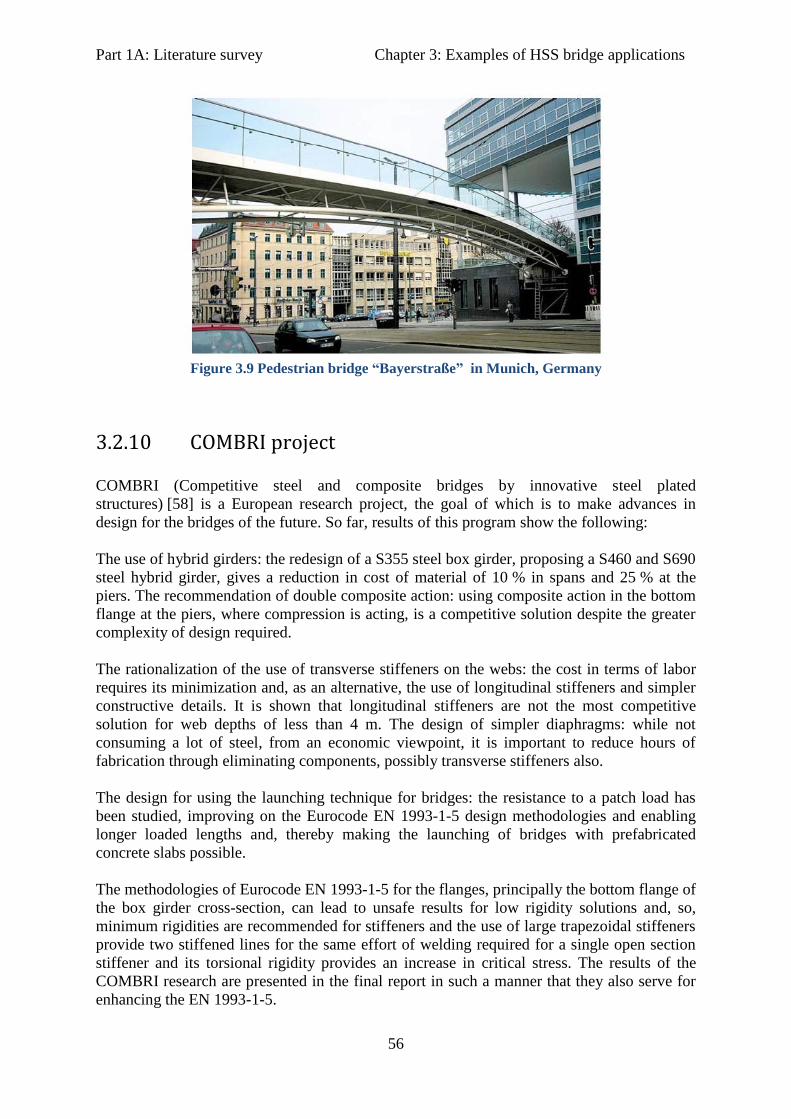
Part 1A: Literature survey Chapter 3: Examples of HSS bridge applications
56
Figure 3.9 Pedestrian bridge “Bayerstraße” in Munich, Germany
3.2.10 COMBRI project
COMBRI (Competitive steel and composite bridges by innovative steel plated
structures) [58] is a European research project, the goal of which is to make advances in
design for the bridges of the future. So far, results of this program show the following:
The use of hybrid girders: the redesign of a S355 steel box girder, proposing a S460 and S690
steel hybrid girder, gives a reduction in cost of material of 10 % in spans and 25 % at the
piers. The recommendation of double composite action: using composite action in the bottom
flange at the piers, where compression is acting, is a competitive solution despite the greater
complexity of design required.
The rationalization of the use of transverse stiffeners on the webs: the cost in terms of labor
requires its minimization and, as an alternative, the use of longitudinal stiffeners and simpler
constructive details. It is shown that longitudinal stiffeners are not the most competitive
solution for web depths of less than 4 m. The design of simpler diaphragms: while not
consuming a lot of steel, from an economic viewpoint, it is important to reduce hours of
fabrication through eliminating components, possibly transverse stiffeners also.
The design for using the launching technique for bridges: the resistance to a patch load has
been studied, improving on the Eurocode EN 1993-1-5 design methodologies and enabling
longer loaded lengths and, thereby making the launching of bridges with prefabricated
concrete slabs possible.
The methodologies of Eurocode EN 1993-1-5 for the flanges, principally the bottom flange of
the box girder cross-section, can lead to unsafe results for low rigidity solutions and, so,
minimum rigidities are recommended for stiffeners and the use of large trapezoidal stiffeners
provide two stiffened lines for the same effort of welding required for a single open section
stiffener and its torsional rigidity provides an increase in critical stress. The results of the
COMBRI research are presented in the final report in such a manner that they also serve for
enhancing the EN 1993-1-5.

Part 1A: Literature survey Chapter 3: Examples of HSS bridge applications
57
3.3 Examples in Japan
3.3.1 Tokyo Gate Bridge (Japan)
The bridge opened in July 2011. The use of high yield strength steel “SBHS” (Steel for
Bridge High Performance Structures), reduced approx. 3 % of the total weight and approx.
12 % of the total construction cost (estimated by MLIT).
Figure 3.10 Tokyo Gate Bridge
3.3.2 Nagata Bridge, Japan
It is suspended over the Tama River, connecting Fussa and Akiruno cities in Tokyo (ordered
by the Tokyo Metropolitan Government Bureau of Construction).It is a four span continuous
bridge, 250m in length The total weight of the steel used is approximately 600 tons.
The Nagata Bridge is the bridge for which SBHS was first adopted after it was established as
JIS steel. SBHS was used because is highly strong and tough, and has excellent weldability
and cold formability when compared to conventional rolled steel for welded structures.
The yield strength, which refers to the design strength in the structural design, is 10-20%
higher than conventional steel. This allows for economical design that includes weight
savings.
Figure 3.11 Nagata bridge, Japan

Part 1A: Literature survey Chapter 3: Examples of HSS bridge applications
58
3.3.3 The Akashi Kaikyo Bridge
The Akashi Kaikyo Bridge forms part of the arterial highway that connects Honshu and
Shikoku. This three-span, two-hinge stiffened truss suspension bridge is 3,911 m long with
the world's longest center span of 1,991 m. Nippon Steel delivered approx. 4,200 tons of
HT690 and HT780 steel for the stiffening girders; this steel can decrease preheating
temperatures.
Figure 3.12 The Akashi Kaikyo Bridge, Japan.
Figure 3.13 Application of HSS in the Akashi Kaikyo Bridge, Japan.
3.4 Bridge examples and case studies in U.S.
Especially in the USA extensive research programs for HPS (high performance steels), in
bridges, have been performed. These help gaining experience and learn more about the use of
these steels in bridges. Some of them are presented here.
In 1992, AISI partnered with the Carderock Division, Naval Surface Walfare centre and the
Federal Highway administration (FHWA), to develop new and improved steel alternatives for
bridges. The team brought together a cadre of professionals in steel production, bridge
design, bridge fabrication and welding, as well as specialists from the U.S. government and
academia.

Part 1A: Literature survey Chapter 3: Examples of HSS bridge applications
59
The result was a new type of steel, known as high-performance steel (HPS), which provided
up to 18 % cost savings and up to 28 % weight savings when compared with traditional steel
bridge design materials. HPS 100W, HPS 70W (485 MPa yield strength) and HPS 50W
(345 MPa yield Strength) produce bridges that are more cost-effective, higher in strength,
lighter in weight, and have greater atmospheric resistance than conventional steels. They also
have improved fatigue and corrosion-resistance properties.
In the International Conference on Transportation Engineering, 2009 (ASCE) was presented a
study on costs of long span bridges with application of HSS. In this study, trial designs of
cable- stayed bridges with main span length of 1400 m, steel weight and construction cost of
the bridges made of different steels named as Q345, Q420, HPS70W and HPS100W of which
their yield points are 345, 420, 485 and 690 MPa, respectively, were investigated. The results
indicate that the steel weight and construction cost can be reduced obviously with the
increase of steel strength, although the design stresses of some plates of the box girder are not
governed by material strength due to the influence of the stability of stiffened plates and the
limitation of minimum plate thickness.
[6] According to U.S. Department of transportation, Federal Highway Administration
(FHWA), there is the need for a fundamental change in the methods and materials used in
bridge construction. A large number of the of the 595,000 highway bridges in U.S. are
substandard or deficient in one or more ways, even after 25 years of federal, state and local
improvement programs. Fatigue and deterioration govern the service life of these structures.
Therefore, FHWA suggests, that it would be a good solution to solve these problems, by fully
implement the use of High Performance Steel for all structural steel bridge elements where
the high strength of HPS leads to fewer lines of girders, shallower beams and longer spans.
These HPS bridges also have improved fatigue and corrosion resistance.
Benefits from the use of HPS in the USA (according to FHWA): - Longer span lengths and fewer piers
- Lower foundation and superstructure costs
- Wider beam spacing and fewer beams
- Increased vertical clearance without expensive approach roadway work
- Fewer maintenance requirements and longer service life
- Lower initial and life-cycle costs
A parametric study conducted of FHWA of two span continuous plate girder bridges with
span lengths of 30 m and 75 m indicated that the optimum girders used ASTM A709 grade
345W (345 MPa nominal yield strength) steel for all webs and positive moment top flanges
and HPS 485 W for the negative moment top flanges and all bottom flanges (AASHTO
2003).
Girder designs consisting entirely of HPS 485W were 13-20 % lighter than those fabricated
entirely from grade 345W, but were about 3 % more expensive due to the higher cost of
material. However as HPS becomes more common in the market its costs is likely to be
reduced.

Part 1A: Literature survey Chapter 3: Examples of HSS bridge applications
60
As a part of a master’s thesis project at the University of Missouri-Columbia in the year
2000 [13], six alternative bridge designs (alternating the number of girders and the material
used) where developed for a particular site.
The purpose of the paper was to demonstrate the benefits of HPS 485W (yield strength of
485 MPa) girder bridges compared to conventional 345W (345 MPa yield strength) steel
girder bridges. Three homogeneous HPS 485W designs where compared to two 345W
designs and also a hybrid design 345W/485W was also explored. For design optimization,
based on current trends, 345W steel was used for all stiffeners, diaphragms and slice
connection plates. The designs followed the AASHTO Standard specifications (16th
edition)
Load Factor method.
The objective was to compare construction, fabrication, erection and shipping costs and find
the most cost effective design. However, the bridge owners were mostly interested in
comparing the total costs.
The study concluded that at the time, and for current prices of the material, the design with
the 7 hybrid girders was the most cost effective (11 % cost savings at the time of the study)
and that lower material costs for HPS will have significant advantages for the use of these
steels in the future (14.6 % was the estimation accounting for projected costs). In the table
below the six design alternatives are presented.
Table 3.4 Bridge design alternatives for cost comparisons, University of Missouri-Columbia
2000 [13]
Another paper, [59] collects experience from the use of HPS in the state of Nebraska and
describes its application in four different projects. The study indicated that the best use of
High Performance Steels is in hybrid construction, as it is more economical and efficient to
use the high strength steel in regions of high tensile stresses (bottom flanges in spans and top
flanges at supports and in regions with high tensile stresses). Two of the projects this paper is
dealing with, are mentioned briefly here.
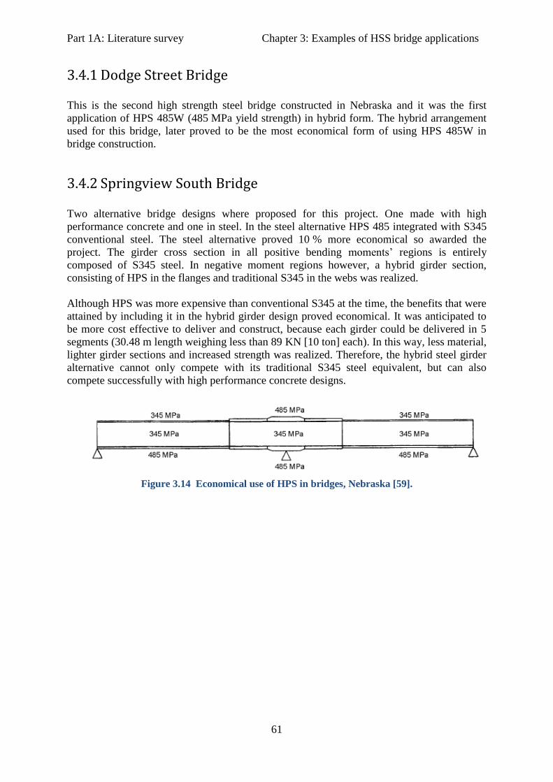
Part 1A: Literature survey Chapter 3: Examples of HSS bridge applications
61
3.4.1 Dodge Street Bridge
This is the second high strength steel bridge constructed in Nebraska and it was the first
application of HPS 485W (485 MPa yield strength) in hybrid form. The hybrid arrangement
used for this bridge, later proved to be the most economical form of using HPS 485W in
bridge construction.
3.4.2 Springview South Bridge
Two alternative bridge designs where proposed for this project. One made with high
performance concrete and one in steel. In the steel alternative HPS 485 integrated with S345
conventional steel. The steel alternative proved 10 % more economical so awarded the
project. The girder cross section in all positive bending moments’ regions is entirely
composed of S345 steel. In negative moment regions however, a hybrid girder section,
consisting of HPS in the flanges and traditional S345 in the webs was realized.
Although HPS was more expensive than conventional S345 at the time, the benefits that were
attained by including it in the hybrid girder design proved economical. It was anticipated to
be more cost effective to deliver and construct, because each girder could be delivered in 5
segments (30.48 m length weighing less than 89 KN [10 ton] each). In this way, less material,
lighter girder sections and increased strength was realized. Therefore, the hybrid steel girder
alternative cannot only compete with its traditional S345 steel equivalent, but can also
compete successfully with high performance concrete designs.
Figure 3.14 Economical use of HPS in bridges, Nebraska [59].

Part 1A: Literature survey Chapter 4: Main points from literature survey
62
4 Conclusions from literature review
High strength steels may offer many benefits when used for bridge design. The main
advantages are generally a result of reduced weight and cross sectional dimensions. Design
stresses can be increased and plate thicknesses may be reduced resulting in significant weight
savings. Reduced plate thickness can also save on welding costs as well as on fabrication,
erection and transportation costs. Foundation costs may also be reduced due to lower dead
weight.
Quenched and tempered (Q&T) high strength steels offer very high strengths for structural
applications (up to 1100 MPa minimum yield strength), thus significant weight savings,
accompanied with high toughness values (even at low temperatures), good weldability and
sufficient ductility (although they have lower fu/fy ratios). These overall properties make this
steels the most appropriate choice in case of bridges.
Their chemical composition can be adjusted according to the specific structural application
demands.
Strength and hardness, generally, decrease with increasing tempering temperature and
holding time. On the other hand tensile tests show that elongation and area reduction increase
as the tempering temperature and holding time increase. For appropriate toughness values
tempering is performed at least at 550 °C.
Weldability is improved due to grain refinement and low CEV values (carbon content usually
around 0.15 %). However, high strength steels seem to be more susceptible to hydrogen
cracking. Generally, as the parent metal increases fewer variations in welding procedure are
allowed.
Preheating temperatures depend on the steel grade and chemical composition. It is generally
not required for plate thicknesses below 30mm.
Post welding heat treatment is generally not recommended for Q&T steels. In addition, they
are not suitable for hot working above 550 °C since this may change their mechanical
properties.
Design codes available today in Europe, for these steels, are only available as additional rules
for steel grades up to S700 (EN 1993-1-12:2007) although quality standards cover steel
grades up to 960 MPa. This lack of detailed European design rules, limits the use of these
higher grades in the construction industry, in Europe.
Especially when talking about economical design of bridges using high strength steel, it is
important to realize that the whole design consideration should change and development of
detailed design codes are essential for gaining the maximum benefits the new material has to
offer. This has been done in U.S and in Japan for several years now.
The price of high strength steel still lies in high levels in comparison to S355, especially in
Europe. This is because the market demands for these grades are still quite limited and only a
few fabricators are able to work with the new material. However, this will change in the
Part 1A: Literature survey Chapter 4: Main points from literature survey
63
future as the market demand is expected to increase, resulting in significant reduction of the
high strength steel price.
In spite of the higher material costs, high strength steel bridges can be more economical in
terms of total costs when properly designed. Total costs include material, fabrication,
erection, transportation and maintenance costs.
To provide the best (high strength) steel quality and gain the maximum profit, it is important
that fabricators will invest in higher quality equipment as a small increase in initial cost may
give a large return on the investment. For small plate thicknesses, however, high strength
steel can be machined as the regular steel grades with no extra investment.
The most economical and efficient use of Q&T steels is in members stressed in tension where
the high strength can be fully exploited, and in projects where the dead weight of steel is the
predominant load (e.g. long span bridges). In compression they are most effective in heavily
loaded, stocky columns or in stiffened compression elements where buckling is not the
controlling criterion. In any case, must be ensured that fatigue or buckling is not the
governing criterion, by proper bridge design.
Hybrid steel girders are welded steel girders which combine different steel grades. Usually
high strength steel is used for the flanges while normal steel grades are used for the web. This
combination is proven to offer the highest level of economy in comparison to homogeneous
steel girders.
Fatigue of welded details usually governs the design of steel and composite (steel-concrete)
bridges. Material strength in that case plays no role and thus properties of high strength steel
cannot be fully utilized since the stress level is limited at critical locations. However,
experimental research shows that these steels do not exhibit any disadvantage in fatigue
resistance compared to mild steels [Puthli et al. (2006)]. In addition, alternative and more
effective design solutions as cast joints, bolted connections where possible, transverse butt
welds and plate thickness increase at critical locations, can greatly improve fatigue
performance. Post weld treatment can also be incorporated, if necessary, to improve further
the fatigue behavior of welded details.
Buckling behavior of high strength steel can be considered better than mild steel in cases of
heavily loaded stocky sections. The main reason for that is that higher steel grades (e.g. S690)
are less sensitive to geometric imperfections in comparison to S355.
Part 1A: Literature survey References
64
References- Part 1A
[1] BlueScope Steel, Australia. “High
Strength Steels - Cost or Economy?” (31
January 2002).
[2] Prof. Dan Dubina, The politechnica
University of Timisoara. “Performance
and benefits of using high strength steels”.
ECCS Annual Meeting Aalesund, 18
September 2008 Technical Meeting
Session.
[3] Prof. Dr.-Ing. Gerhard Sedlacek, Dipl.-
Ing. Christian Müller. “High Strength
Steels in Steel Construction”. Institute of
Steel Construction, RWTH Aachem,
Germany.
[4] Anders Samuelsson¹, Falko Schröter².
“High performance steels in Europe-
Production Processes, mechanical and
Chemical Properties, Fabrication
Properties”. ¹PhD, SSAB Oxelösund,
Sweden, Dr.-Ing., ²Dillinger Hütte GTS,
Germany.
[5] Colin Macdougall¹, Robert G. Driver²,
Gilbert Y. Grondin². “A State-of-the-Art
Review of High Performance Steel for
Bridge Design”. ¹Assistant Professor,
Dept.of Civil Engrg., Queen’s University,
Kingston, Canada, ² Associate Professor,
Dept. of Civil & Envir. Engrg. University
of Alberta, Edmonton, Canada.
[6] Vasant C. Mistry, Federal Highway
Administration: “High Performance Steel
for Highway Bridges”. Paper 1, (2005).
[7] Worldsteel Association: “Steels for
Modern Bridge Construction”.
[8] Key to Metals: “Application of Micro-
alloyed HSLA Steel: Part One”.
[9] Wikipedia-The Free Encyclopedia:
“High-Strength Low-Alloy steel (HSLA)”.
[10] BSS Steelstrip - Cold Rolled, mild
steel and high carbon steel strip suppliers
for the UK: “HSLA steels”.
[11] HSLA-V, Vanadium steel technology:
HSLA-V Steel. High-Strength Low-Alloy
steel Micro-alloyed with Vanadium.
[12] SMDI - Steel Market development
Institute: “High Performance Steel
Bridges”.
[13] Michael G. Barker, Steven D.
Schrage. “High performance Steel: Design
and Cost Comparisons”. Bridge Crossings-
practical information For the Bridge
industry, No. 16 (June 2000).
[14] SteelTalk.com: “Special alloy steels-
Quenched and Tempered Steels”.
[15] “Review of the performance of high
strength steels used offshore”. Research
report 105, prepared by Cranfield
University for the Health and Safety
Executive (HSE), 2003.
[16] Miki C., Ichikawa A., Kusunoki T.,
Kawabata F. “Proposal for Bridge high
performance steels (BHS500/BHS700W),
Collection of papers of Japan society of
civil engineers. (738/I-64), 1-10 (July
2003).
[17] Wikipedia- The Free Encyclopedia:
“Honshū-Shikoku Bridge Project”.
[18] Klaus Richter, Frank Hanus, Peter
Wolf. “Structural Steels of S690 MPa
yield Strength- A State of Art”. Dillinger
Hütte- Quality Department.
[19] Masteel: “S690QL High Yield
Structural Steel - Properties and
Applications”.
[20] Leeco Steel- O’Neal Industrial Metals
Group: “S690 European Standard Steel”.
Part 1A: Literature survey References
65
[21] MetalPass-resource: “Structural steel
metallurgical characteristics and
properties”, paper (2002)
[22] Kaiser H-J, Kern A. Schriever U and
Wegmann H., “Fracture toughness of
modern high strength steel plates with
minimum yield strength up to S690 MPa”.
In: Proceeding of International symposium
“Safety in application of high strength
steel”, Trondheim, Norway, 1-2 July 1997,
publ. Statoil, Norway.
[23] MIT- Department of Civil and
Environmental Engineering. ”Chemical
Composition of Structural Steels”. §1.51-
Design of Steel Structures (1999).
[24] Ana M. Girão Coelho et al.
“Deformation Consideration for High
Strength Steel Moment Connections”.
D.Camotim et al. (Eds.), Lisbon, Portugal,
September 6-8 (2006): “Stability and
Ductility of Steel Structures”.
[25] Key to metals: Article: “Multi Phase
Twinning-Induced Plasticity (TWIP)
Steel”.
[26] Dr.-Ing. Frank Hanus, Dr.-Ing. Falko
Schröter, Dipl.-Ing. Wolfgang Schütz.
“State of art in the production and use of
high-strength heavy plates for hydropower
applications”. Dillinger Hütte GTS,
Hüttenwerk, Dillingen. Paper presented at
the conference “High strength steel for
Hydropower Plants”, Graz, 05-07.07.2005.
[27] Woei -Shyan Lee, Tzay-Tian Su.
Mechanical Properties and Microstructural
features of AISI 4340 high-strength alloy
steel under quenched and tempered
conditions. Department of Mechanical
Engineering, National Cheng Kung
University, Tainan 701, Taiwan. Journal of
materials Processing Technology 87
(1999) 198 – 206.
[28] SSAB Swedish Steel-Uddeholm
Tooling.”Tooling Solutions for advanced
high strength steels”
[29] RUUKKI.” Hot rolled steel sheets
plates and coils- Mechanical Cutting”.
MFI.001EN/08.2011/AN. Helsinki, Finland.
[30] AISC-American Institute of Steel
Construction. “Will rising ore pricing
impact the price of structural steel?” (April
5, 2010).
[31] Robert A. P. Sweeney, et al. “Steel
Bridges”. A2C02: Committee on Steel
Bridges, Chairman: Robert A.P. Sweeney,
1989.
[32] Dr. Masatsugu Nagai. “Steel Bridges -
Rationalized design methods in Japan”.
Professor, Nagaoka University of
Technology. Included in Paper No. 15,
presented in JIFC-Japan Iron and Steel
Federation-, July 2006.
[33] Koji Homma, Kazumi Matsuoka,
Hirofumi Kawasaki, Mutsuto Tanaka,
Tadashi Kasuya. “Development of
Application Technologies for Bridge High
Performance Steels BHS”. Nippon Steel
technical report No. 97 January 2008,
UDC 699. 14. 018. 292: 624. 3
[34] A.M. Gresnight, S.M. Steenhuis. High
Strength Steels. Delft University of
Technology, The Netherlands. TNO
Building and Construction Research,
Delft, The Netherlands
[35] Güven kiymaz. Stability and strength
criteria for High Performance Steel Plates
under Edge Compression. Journal of
Istanbul Kültür University 2003/3, pp. 1 -
26.
[36] Peter Collin¹, Bernt Johansson².
“Bridges in High Strength Steel”. ¹ Prof.
Composite Structures LTU/Ramböll,
Part 1A: Literature survey References
66
Sweden ,² Prof. Steel Structures LTU,
Sweden.
[37] Prof.Dr.-Ing. Utrike Kuhimann, Dr.-
Ing. André Dürr, Dr.-Ing. Hans-Peter
Günther. Longer service life by improved
fatigue resistance applying post-weld
treatment methods. University of Stuttgart-
Institute of structural design. COST C25
Oslo, 2007.
[38] R.J.M. Pijpers¹ ², M.H. Kolstein², A.
Romeijn², F.S.K. Bijlaard². “Fatigue
strength of hybrid VHSS-Cast steel welded
plates”. ¹The materials innovation Institute
(M2i), Delft, the Netherlands. ²Delft
university of Technology, Delft, the
Netherlands (NSCC2009).
[39] Zijah Burzić et al. “Fatigue Properties
of a High Strength Steel Welded Joint”.
ISSN 1580-2949 - MTAEC9,
41(4)163(2007).
[40] S. Beretta, A. Bernasconi, M.
Carboni. “Fatigue assessment of root
failures in HSLA steel welded joints: A
comparison among local approaches”.
Politechnico di Milano, Dipartimento di
Meccanica, Via La Masa 1, I-20156
Milano, Italy. International journal of
fatigue 31 (2009), p.102-110.
[41] A. Bignonnet, H.P.Lieurade, L.
Picouet. Improvement of the fatigue life
for offshore welded connections. Institut
de Reherches de la Sidérurgie Français
(IRSID), 78105 saint Germain en Laye
Cedex, France.
[42] M.H. Kolstein¹, O.D. Dijkstra².
“Fatigue tests on welded connections made
of VHSS”. ¹TU-Delft University of
Technology- Faculty of Civil Engineering
and Geosciences, ²TNO Building and
Construction Research, Delft, Netherlands.
[43] J. Ménigault, J. Claeys, J.M. Vigo, Y.
Le Guernic. Improving the fatigue
resistance of stiffener- lower flange
connection in steel bridge beams. France,
1996.
[44] R.J.M. Pijpers¹ ², M.H. Kolstein², A.
Romeijn, F.S.K. Bijlaard². The fatigue
strength of base materials and butt welds
made of S690 and S1100. ¹Netherlands
Institute for metals research, Delft,
Netherlands. ²Delft university of
Technology, Delft, Netherlands. 5th
International conference on Advances in
Steel Structures, Singapore, 5-7 December
2007.
[45] R.J.M. Pijpers¹ ², M.H. Kolstein², A.
Romeijn, F.S.K. Bijlaard². The fatigue
strength of butt welds made of S690 and
S1100. ¹Netherlands Institute for metals
research, Delft, Netherlands. ²Delft
university of Technology, Delft,
Netherlands.
[46] M.H. Kolstein, O.D. Dijkstra.
“Numerical modelling of under matched
welded high strength steel connections”,
(2006). TU-Delft University of
Technology - Faculty of Civil Engineering
and Geosciences and TNO Building and
Construction Research, Delft, Netherlands.
[47] M.H. Kolstein, F.S.K. Billiards, O.D.
Dijkstra. “Static strength of welding
connections made of very high strength
steel” (2006). TU-Delft University of
Technology - Faculty of Civil Engineering
and Geosciences and TNO Building and
Construction Research, Delft, Netherlands.
[48] M.H. Kolstein, F.S.K. Bijlaard, O.D.
Dijkstra. “Deformation Capacity of welded
joints using high strength steel”. TU-Delft
University of Technology - Faculty of
Civil Engineering and Geosciences and
TNO Building and Construction Research,
Delft, Netherlands. 5th
International
conference on Advances in Steel
Structures, Singapore, 5-7 December 2007.
[49] M.H. Kolstein, F.S.K. Bijlaard, O.D.
Dijkstra. Integrity of welded Joints made
Part 1A: Literature survey References
67
of Steel grades S690 and S1100 (2006).
TU-Delft University of Technology -
Faculty of Civil Engineering and
Geosciences and TNO Building and
Construction Research, Delft, Netherlands.
[50] M.H. Kolstein, O.D. Dijkstra. “Tests
on welded connections made of High
strength steels up to 1100 MPa (2006)”.
TU-Delft University of Technology -
Faculty of Civil Engineering and
Geosciences and TNO Building and
Construction Research, Delft, Netherlands.
[51] M. Veljkovic, B. Johansson. “Design
of Hybrid Steel Girders” . Division of
Steel Structures, Lulea University of
Technology, Lulea SE-971 87, Sweden.
Journal of Constructional Steel research 60
(2004) p.535 - 547.
[52] MetalPass-resource: “5.2.
Construction- 5.2.1Light gauge
construction: 4) Bridge & Building “,
paper (2002).
[53] Michael Korchynsky. “ A New Role
for Microalloyed Steels-Adding economic
value”. Consultant in Metallurgy. U.S.
Vanadium Corporation .A Subsidiary of
Strategic Minerals Corporation, Pittsburgh.
Pennsylvania.
[54] Worldsteel Association-Types of
Bridges.
[55] Prof. Frans Bijlaard, Dr. Henk
Kolstein. CT 5125-Steel bridges, ESDEP
Lecture 1B_6_1&2 Introduction to design
of steel and composite bridge, lectures
2010-2011, TU-Delft.
[56] Corus Construction Centre - Bringing
steel to life. Bridge related products and
services.
[57] Dillinger Hütte -DI-MC steels for
constructional steelwork. Bridges in The
Netherlands.
[58] EurekAlert! Online global news
service operated by AAAS, the science
society. COMBRI, a research project for
designing bridges of the future.
[59] Atorod Azizinamini, P.E., Kristin Van
Ooyen, Fouad Jabar, Sam Fallaha. High
Performance Steel Bridges: Evolution in
Nebraska. Annual meeting of the
Transportation Research Board (Jan.
2003), Washington, D.C.
[60] Kenneth Håkansson. “Weld Metal
Properties for Extra High Strength Steels”.
Doctoral thesis report 2002-August.
Division of Welding- Department of
Production Engineering, The Royal
Institute of Technology (KTH).ISSN
1650-1888
[61] TWI Research and Technology
Organisation, Cambridge, U.K.
[62] Ir. Cor Speksnjider. Hoofd
Engineering. Mercon Steel Structures
B.V., Gorinchem, the Netherands.
[63] P.J. Haagensen and SJ. Maddox,
XIII-1815-00. “IIW recommendations on
post weld improvement of steel and
aluminium structures”. The international
institute of welding (IIW), July 2003
Part 1B
68
Part 1B Preliminary design
In Part 1B (chapters 5 and 6), a long single span (L=105 m) roadway bridge crossing
Amsterdam-Rijnkanaal in the Netherlands, the ‘Schellingwouderbrug’, is chosen as a
reference bridge to be re-designed using HSS. Three bridge type alternatives (based on the
specific bridge geometry, location and site restrictions) are considered and preliminary
designs are performed separately for each alternative. Design criteria are mainly strength,
stability and fatigue. Also bridge weight and associated costs influence the design. Finally,
the main results are summarized in chapter 6. More information on modeling and calculations
are included in Appendix A.

Part 1B Preliminary bridge design Chapter 5: General
69
5 Preliminary bridge designs using HSS
5.1 Setting the scene
5.1.1 Material choice
In Europe, quenched and tempered high strength steels are appeared to offer maximum
weight savings for heavy constructions. In this thesis, S690 (in Q&T delivery condition) steel
grade is chosen to be the upper limit of HSS grades to be used for the bridge design, in order
to explore the maximum possible benefits of HSS.
Higher steel grades are not considered beneficial in case of bridges, since it is more likely
that at very slender cross sections, stability and fatigue will be the governing factors. In
addition, S700 is the upper limit for the yield strength which is covered by the European
design codes [EN 1993-1-12:2007].
Hybrid bridge designs are performed using high strength steel S690 (and S460) in
combination with mild steel grade S355.
5.1.2 Scope and planning
This thesis aims to examine the possibility of developing a structurally safe but also cost
effective design using HSS, in order to enhance the use of higher steel grades for future
applications in bridges in the Netherlands and generally in Europe. To accomplish that, the
geometry and location of a long span roadway steel bridge (all in grade S355) in the
Netherlands will be considered as reference.
The design phase is divided in two main parts:
Firstly, bridge type alternatives are considered, using high strength steel, for the reference
bridge (i.e. based on geometry and location) and preliminary designs are performed for each
bridge type. The bridge type (truss, arch, etc.) is chosen based on economic span lengths and
L/D ratios, found in literature.
In the second part, one of the preliminary (global) designs that satisfy all design criteria
(strength, fatigue, stability) is chosen based on minimum steel self-weight. Then, a detailed
global design is performed (i.e. design of connections for strength and fatigue). The total
costs for this design are then estimated on terms of material (dead weight and weld volume),
fabrication, transportation, erection and maintenance costs.
Reference is made to the Appendixes at the end of this study (Appendix A and Appendix B)
for detailed information on trial designs.
Due to time limitation it is not possible to perform a complete new global design in S355,
also. Nevertheless, estimation on member dimensions, plate thicknesses, structural weight
and related costs, for the final design choice, is attempted for comparison.

Part 1B Preliminary bridge design Chapter 5: General
70
It is important to mention here that different design philosophy is needed to make effective
and economic use of both materials (i.e. mild steel grades and HSS grades). Thus, results
from this comparison should be treated with care.
Finally, conclusions for steel bridge design, using high strength steel are drawn. Also,
recommendation for further research is given.
5.1.3 The reference bridge 5.1.3.1 ‘SCHELLINGWOUDERBRUG’
The so called ‘Schellingwouderbrug’ in Amsterdam (opened in 1957), is a steel arch bridge
crossing the Amsterdam-Rijnkanaal in the Netherlands. The renovation of this steel arch
bridge is part of the ‘KARGO’ project for maintenance and renovation of several steel
bridges (fixed and movable) in the Netherlands. This project started in September 2011 and
expected to finish in June 2012.
Figure 5.1 Bridges covered by the KARGO (Kunstwerken Amsterdam-Rijnkanaal Groot
Onderhoud) project [Rijkswaterstaat].
The bridge is in the range of medium to large span bridges in the Netherlands and thus, it is
expected that the benefits of using HSS will be more pronounced than for small spans,
especially due to higher self-weight in relation to fatigue loading. In addition, an important
role in the choice played also the interest of Iv- Infra on these span lengths for future design
projects.

Part 1B Preliminary bridge design Chapter 5: General
71
5.1.3.2 BRIDGE GEOMETRY
The steel arch roadway bridge, ‘Schellingwouderbrug’ (Figure 5.2), has a single span of
105.30 m which is simply supported at its two end piers on four bearings. Its width, 16.30 m
in total, consists of a double lane roadway (one per direction) and two cantilevers, 3.60 m
each, for cycle/ foot paths. The construction depth is limited to only 1.65 m below the deck,
due to clearance requirements to facilitate river traffic [1].
Figure 5.2 Left: The ‘Schellingwouderbrug’, Amsterdam [Rijkswaterstaat]. Right: the location
of the bridge [Gemeente Amsterdam]
Figure 5.3 Bridge geometry: cross sectional view. Maximum construction depth is limited to
1.65 m below the deck level.

Part 1B Preliminary bridge design Chapter 5: General
72
5.2 Basis of Design
5.2.1 Conceptual choice 5.2.1.1 MAIN LOAD CARRYING SUPERSTRUCTURE
Generally, when selecting the “correct” bridge type, it is important to find a structure that will
perform its required function and present an acceptable appearance at minimum costs. In that
respect different types have to be examined before the final decision.
The initial choice for the bridge type is based on cost effective span lengths and L/D ratios,
derived from previous experience.
Thus, given the bridge geometry, general guidelines provided by several scientific documents
(e.g. [2], [3], [4], and [5]), for a single span simply supported bridge with length over 100 m;
suggest that economic solutions for the longitudinal structural system generally are:
- Trough truss (span to depth ratios: L/D= 10-15)
- Box girders (span to depth ratios: L/D= 20-30)
- Arches
- Cable stayed
Thus, for the span of 105.30 m and taking into account also the location and constructional
restrictions for the reference bridge two types for the longitudinal system are the most
suitable: a truss and an arch bridge (a cable stayed bridge is not considered due to difficulties
of locating the pylons and anchor the cables).
The box girder bridge, although conflicting with the L/D ratios found in literature (should be
around 20-30) is chosen to be examined, just for research purposes. The author thought it
would be interesting to check, whether it is possible to achieve higher L/D ratios by using
S690 for the bottom (tensile) flange of the box. This requires extensive research, however,
and cannot be covered explicitly in this thesis study.
For the main structure, combination of different steel grades (hybrid construction), e.g. S355
and S690 (Q&T), will be considered, with respect to the highest level of economy. Therefore,
S690 is applied on members and/or regions of high stresses, and lower grades elsewhere.
Especially when strength is governing, using S690 for the whole section will reduce the dead
weight and plate dimensions, thus overall costs, significantly.
5.2.1.2 DECK
For the deck structural system 2 possibilities can generally be considered.
- The deck system being part of the main superstructure.
- The deck system acting separately.
The first option is generally considered as more cost effective solution when concrete deck
acts compositely with the main structure or when the orthotropic deck acts as the top flange
of the main girders.
Part 1B Preliminary bridge design Chapter 5: General
73
In such case, the deck system is designed continuous along and across the span. This
continuity (plate action) ensures that it will participate to the overall structural action of the
superstructure. Its principal function is to provide support to local vertical loads (from
highway traffic and pedestrians) and transmit these loads to the primary superstructure of the
bridge [4].
However, in the case an orthotropic steel deck is being used, fatigue may be critical as many
fatigue sensitive details will be present. Furthermore, for new bridges, a design life of 100
years is required and therefore the design requirements with respect to fatigue (and
maintenance) will more likely not benefit the use of high strength steel.
Taking into account these problems, it could be then wise to consider the deck as lying on top
of the cross beams (maybe in composite action) and not on the main girders, and design it
such that it could be possible to remove it and replace it any time (maintenance
requirements), independently of the rest of the bridge (second option). In this case the design
life for the deck can be 30 years or even less, and thus the requirements for fatigue far more
relaxed.
Another advantage that this second option can offer is that makes it possible to use any
material of preference (e.g. FRP, timber etc.) for the deck, and not limit possible choices in
orthotropic steel deck and concrete.
The cost effectiveness of such an option can be an interesting subject for further
investigation.
For the ‘Schellingwouderbrug’, the deck structure is not considered in detail for global
designs. For sake of simplicity and to be benefited from the higher dead weight (i.e. higher
static load will make higher steel grade more effective) concrete deck is generally adopted as
the deck system in ‘Schellingwouderbrug’.
Exception is made in case of the box girder bridge, where orthotropic steel deck is used, and
also acts as the top flange of the box girder. This is done so, because, due to the extremely
small depth of the box girder in comparison to the bridge length (i.e. very large L/D ratio) the
deflections is expected to be quite high, thus a concrete deck would just made the situation
even worse (higher dead weight than orthotropic deck).
5.3 Preliminary bridge designs
5.3.1 General
In this stage the bridge configuration and the materials to be used in the design are
determined. For analytical description and calculations, reference is made to Appendix A.
For the ‘Schellingwouderbrug’ three bridge type alternatives are considered and preliminary
trial designs are performed for each alternative, namely:
A) Box Girder Bridge
Part 1B Preliminary bridge design Chapter 5: General
74
B) Truss bridge
C) Arch bridge
The design criteria are: strength, fatigue, and stability. A check for stiffness (in terms of
maximum vertical deflection at midspan) is only performed in case of the box girder due to
the very slender box structure and clearance requirements below the bridge.
Total costs (material, fabrication, erection, transportation costs) will also play major role for
the final choice between different possible designs.
5.3.2 Global analysis
For the calculation of internal forces, elastic global analysis is used for bridges. This requires
that the stresses (from loading) are limited to the yield strength of the material. Linear stress
distribution over the cross section and linear stress-strain relation is assumed.
For calculating the resistance, plastic or elastic cross sectional properties may be used
depending on the classification of steel members [EN 1993-1-1, EN 1993-2].
5.3.3 Loads
Only vertical loads due to dead load (steel self-weight, deck, asphalt layer, additional dead
loads etc.) and traffic loads are considered for global verifications.
Loads and load combinations are determined based on European Standards.
Load combinations are taken from EN 1990:2002-Eurocode: Basis of structural design
(Annex A2: Application for bridges).
Dead loads are calculated according to EN 1991-1-1:2002 (Eurocode 1: Actions on
structures-Part 1.1: General actions, densities, self-weight, imposed loads on buildings)
depending on the material.
Traffic loads on the bridge are calculated using the European standards for actions on
roadway bridges EN 1991-2:2003 (Eurocode 1: Actions on structures- Part 2: Traffic loads
on bridges. For strength verification group load model gr1a for traffic loads is applied, while
for fatigue check, FLM3 (heavy truck) is applied in the preliminary phase to estimate the
maximum fatigue stress range caused by traffic.
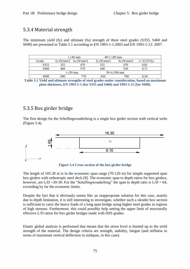
Part 1B Preliminary bridge design Chapter 5: Box girder bridge
75
5.3.4 Material strength
The minimum yield (fy) and ultimate (fu) strength of three steel grades (S355, S460 and
S690) are presented in Table 5.1 according to EN 1993-1-1:2003 and EN 1993-1-12: 2007.
t ≤40 mm 40<t ≤80 mm
Grade fy (N/mm²) fu (N/mm²) fy (N/mm²) fu (N/mm²) ε=√(235/fy)
S355 355 470 355 470 0,81
S460 460 570 440 550 0,71
t ≤50 mm 50<t≤100 mm
S690 690 770 650 760 0,58
Table 5.1 Yield and ultimate strengths of steel grades under consideration, based on maximum
plate thickness, EN 1993-1-1 (for S355 and S460) and 1993-1-12 (for S690).
5.3.5 Box girder bridge
The first design for the Schellingwouderbrug is a single box girder section with vertical webs
(Figure 5.4).
Figure 5.4 Cross section of the box girder bridge
The length of 105.30 m is in the economic span range (70-120 m) for simple supported span
box girders with orthotropic steel deck [8]. The economic span to depth ratios for box girders,
however, are L/D =20-30. For the “Schellingwouderbrug” the span to depth ratio is L/D = 64,
exceeding by far the economic limits.
Despite the fact that it obviously seems like an inappropriate solution for this case, mainly
due to depth limitation, it is still interesting to investigate, whether such a slender box section
is sufficient to carry the heavy loads of a long span bridge using higher steel grades in regions
of high stresses. Furthermore, this could possibly help setting the upper limit of structurally
effective L/D ratios for box girder bridges made with HSS grades.
Elastic global analysis is performed that means that the stress level is limited up to the yield
strength of the material. The design criteria are strength, stability, fatigue (and stiffness in
terms of maximum vertical deflection in midspan, in this case).
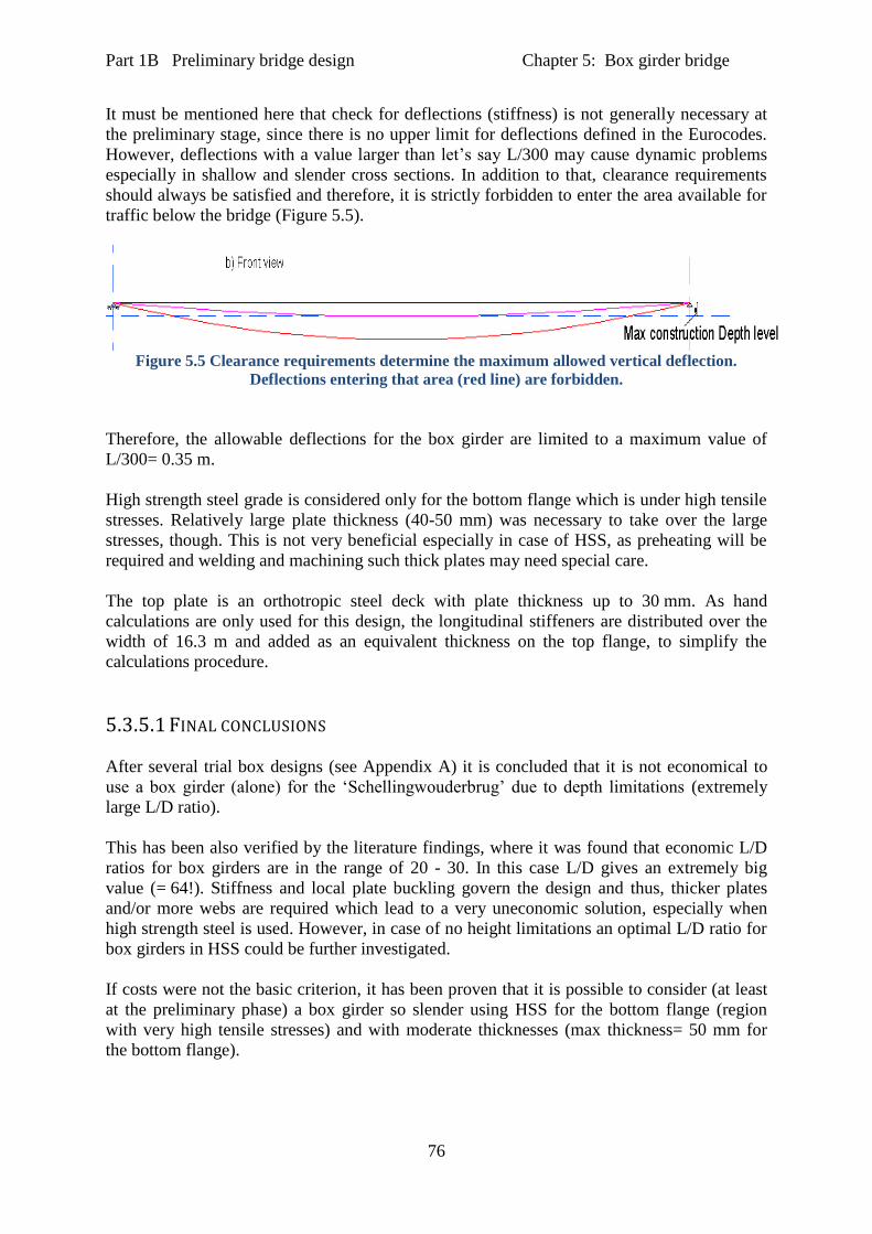
Part 1B Preliminary bridge design Chapter 5: Box girder bridge
76
It must be mentioned here that check for deflections (stiffness) is not generally necessary at
the preliminary stage, since there is no upper limit for deflections defined in the Eurocodes.
However, deflections with a value larger than let’s say L/300 may cause dynamic problems
especially in shallow and slender cross sections. In addition to that, clearance requirements
should always be satisfied and therefore, it is strictly forbidden to enter the area available for
traffic below the bridge (Figure 5.5).
Figure 5.5 Clearance requirements determine the maximum allowed vertical deflection.
Deflections entering that area (red line) are forbidden.
Therefore, the allowable deflections for the box girder are limited to a maximum value of
L/300= 0.35 m.
High strength steel grade is considered only for the bottom flange which is under high tensile
stresses. Relatively large plate thickness (40-50 mm) was necessary to take over the large
stresses, though. This is not very beneficial especially in case of HSS, as preheating will be
required and welding and machining such thick plates may need special care.
The top plate is an orthotropic steel deck with plate thickness up to 30 mm. As hand
calculations are only used for this design, the longitudinal stiffeners are distributed over the
width of 16.3 m and added as an equivalent thickness on the top flange, to simplify the
calculations procedure.
5.3.5.1 FINAL CONCLUSIONS
After several trial box designs (see Appendix A) it is concluded that it is not economical to
use a box girder (alone) for the ‘Schellingwouderbrug’ due to depth limitations (extremely
large L/D ratio).
This has been also verified by the literature findings, where it was found that economic L/D
ratios for box girders are in the range of 20 - 30. In this case L/D gives an extremely big
value (= 64!). Stiffness and local plate buckling govern the design and thus, thicker plates
and/or more webs are required which lead to a very uneconomic solution, especially when
high strength steel is used. However, in case of no height limitations an optimal L/D ratio for
box girders in HSS could be further investigated.
If costs were not the basic criterion, it has been proven that it is possible to consider (at least
at the preliminary phase) a box girder so slender using HSS for the bottom flange (region
with very high tensile stresses) and with moderate thicknesses (max thickness= 50 mm for
the bottom flange).
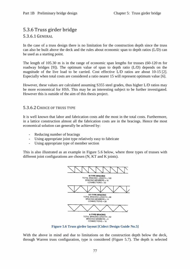
Part 1B Preliminary bridge design Chapter 5: Truss girder bridge
77
5.3.6 Truss girder bridge 5.3.6.1 GENERAL
In the case of a truss design there is no limitation for the construction depth since the truss
can also be built above the deck and the rules about economic span to depth ratios (L/D) can
be used as a starting point.
The length of 105.30 m is in the range of economic span lengths for trusses (60-120 m for
roadway bridges [9]). The optimum value of span to depth ratio (L/D) depends on the
magnitude of the live load to be carried. Cost effective L/D ratios are about 10-15 [2].
Especially when total costs are considered a ratio nearer 15 will represent optimum value [6].
However, these values are calculated assuming S355 steel grades, thus higher L/D ratios may
be more economical for HSS. This may be an interesting subject to be further investigated.
However this is outside of the aim of this thesis project.
5.3.6.2 CHOICE OF TRUSS TYPE
It is well known that labor and fabrication costs add the most in the total costs. Furthermore,
in a lattice construction almost all the fabrication costs are in the bracings. Hence the most
economical solution can generally be achieved by:
- Reducing number of bracings
- Using appropriate joint type relatively easy to fabricate
- Using appropriate type of member section
This is also illustrated as an example in Figure 5.6 below, where three types of trusses with
different joint configurations are chosen (N, KT and K joints).
Figure 5.6 Truss girder layout [Cidect Design Guide No.5]
With the above in mind and due to limitations on the construction depth below the deck,
through Warren truss configuration, type is considered (Figure 5.7). The depth is selected

Part 1B Preliminary bridge design Chapter 5: Truss girder bridge
78
based on economic L/D ratios and the panel length Li is chosen to be constant over the full
length.
Figure 5.7 Warren truss configuration
Where,
H is the total construction height
D is the depth of the truss regarding L/D ratios (between center lines of chord members).
Li is the length of the truss panel (field length)
θ is the brace inclination
5.3.6.3 CHOICE OF CROSS SECTIONS
For the truss members subject to high axial forces (chords and braces), bending (chords and
braces) and torsion (chords) and also thinking in terms of fabrication costs and overall
economy, RHS are initially chosen (and circular-tubular- hollow sections, later on).
RHS members have evolved as a practical alternative for CHS members. This is because,
- No specialized profiling is required allowing easy connections to the flat face which
makes them popular for columns and trusses.
- Structures made with RHS members are more economic to fabricate than with CHS
members [3], if complete automated equipment is not available, because end cutting
for joints with CHS require special profile which is much more expensive (when
needs to be made manually or semi-automatically)
- If the deck is laid directly on the chord member, RHS offer superior surfaces to CHS
for attaching and supporting the deck.
- Additional aspects need to be considered when choosing between RHS and CHS are
the relative ease of fitting weld backing bars to RHS and of handling and stacking
RHS. The latter is important because material handling is said to be the highest cost in
the shop.
- Literature findings point towards a promising bridge design with HSS when truss
designs with CHS members (and moreover with cast joints especially for large span
bridges) are chosen, and thus majority of experimental testing and research are
concentrated around CHS only.
Part 1B Preliminary bridge design Chapter 5: Truss girder bridge
79
Therefore, to enhance the knowledge of RHS members in bridge design, RHS members are
initially chosen for the ‘Schellingwouderbrug’. This is mainly based on the personal
preference of the author to examine the possibility and suitability of RHS members, when
high strength steel grades are to be used for bridge design.
The cross beams, however, mainly act in bending, so I- section profile (usually welded out of
plates) is chosen.
5.3.6.3.1 Advantages of hollow sections over open sections
These sections offer structural advantages especially in case of members subject to
compression and/or in torsion. Considering also their efficiency for lateral stability due to
significant large torsional stiffness they offer a highly suitable solution for lattice girders [3].
Circular hollow sections (CHS) offer a pleasing shape but specialized profiling is needed
when joining circular shapes together. Rectangular hollow sections (RHS) on the other hand
offer an alternative allowing easy connections to the flat face and they are very popular for
trusses.
5.3.6.3.2 Economy
Fabrication costs (in terms of labor hours required to produce a certain structural component)
need not to be more for hollow sections than for open sections. In fact, they can even be less
depending on the joint configurations. The efficiency of hollow sections joints is a function
of a number of parameters which are defined by the dimensions of the connecting members.
Rectangular hollow sections are not standardized in very large dimensions and especially for
HSS, thus they are usually made out of plates welded together (i.e. four longitudinal welds
are required to create a RHS section).
On the other hand, for CHS a single longitudinal weld is required. In that respect fabrication
costs may be lower in comparison to RHS members. In addition, CHS members are
standardized in rather large dimensions (e.g. maximum available is 660x50 for S355 steel
grade) and can be ordered from stock, directly, thus costs are reduced significantly.
Handling and erecting costs can be less for hollow section trusses than for alternative trusses.
They have greater stiffness and lateral strength and that makes it easier to pick up and more
stable to erect. Furthermore trusses made of hollow sections may be lighter than in case of
different sections. In addition, for truss members mainly axially loaded, hollow sections
represent the most efficient use of a steel cross section in compression.
Protection costs are appreciably lower for hollow sections trusses than for other trusses.
Hollow sections trusses may have lower section sizes due to their higher structural efficiency.
The absence of re-entrant corners makes the application of paint easier and the durability is
longer.

Part 1B Preliminary bridge design Chapter 5: Truss girder bridge
80
It is false economy to try to attempt to minimize the mass by selecting a multiple of sizes for
the braces. It is more preferable to use the same section size for a group of brace members.
CHS joints are more expensive to fabricate than RHS due to end cut (i.e. straight bevel cuts
for RHS while more expensive profile end cuts required for CHS when the tubes are to be
directly welded together).
5.3.6.4 MODEL
The model of the truss bridge is made by using beam elements in Scia Engineer FE program
(Figure 5.8). The chords are modeled as continuous beam elements over the whole length.
The braces are modeled hinged on both sides for strength and stability checks. For the fatigue
check rigid connections between chord and brace members are modeled to include the
influence of secondary bending moments in the brace members.
Wind bracing is not included in the model since its presence does not affect the load carrying
capacity under vertical loads. However, is theoretically being considered in terms of stability.
Figure 5.8 3D FEM model in “Scia Engineer”, L/D= 15, Li = 10.5 m
The superstructure consists of the two vertical truss planes (Warren type) connected with
cross beams every 3 m. The concrete deck rests on top of the cross beams (not in composite
action). The traffic loads are positioned directly on top of the cross beams.
The bridge is simply supported on its two ends. The supports are chosen such that the bridge
members can freely expand or shrink in case thermal fluctuations (Figure 5.9 and 5.10).

Part 1B Preliminary bridge design Chapter 5: Truss girder bridge
81
Figure 5.9 Support condition- Left end
Figure 5.10 Support condition- Right end
5.3.6.5 MATERIAL CHOICE
Depending on the maximum stress level in each member, high strength steel grade, S690, is
used for the chord members, S460 is applied usually in the more heavily loaded compression
brace members, due to stability requirements (end braces) and to the most heavily loaded
tension braces. S355 is used in the rest of the braces and in the cross beams.
5.3.6.6 RESULTS
Two preliminary designs for the truss bridge model in Figure 5.8 (see also Appendix A), have
been developed each of which satisfy the main three design criteria strength, stability and
fatigue. Fatigue stresses, according to FLM3 are not governing in any truss design.
On the other hand, buckling of compression members found to be critical in some cases.
However, the stresses are kept at relatively high levels and the cross sectional dimensions
relatively small. A more accurate fatigue calculation is recommended.

Part 1B Preliminary bridge design Chapter 5: Arch bridge
82
Initially, another truss model had also been attempted with larger field length (Li = 15 m).
Stability was governing that design due to extremely large, unsupported, member lengths.
This design, however, is also included in appendix A.
Thus, use of high strength steel seems to be beneficial and a more detailed design together
with total cost estimations should be considered. Also the use of circular hollow sections with
cast joints is interesting to be investigated. Finally, truss optimization can potentially lead to
an economic and effective bridge design with high strength steel.
5.3.7 Arch bridge 5.3.7.1 GENERAL
Steel arch bridges are generally an economic solution for spans 50-500 m [2]. The type of
arch bridge used depends largely on the type of loading (highway or railway). An increase of
loading, especially traffic loading, results for optimum design in an increase of arch
height ‘f’.
Generally the f/L ratio is the nearly the same for highway and railway bridges and varies
between 0.13-0.18 [3].
5.3.7.2 CHOICE OF ARCH TYPE
In case of an arch bridge design for the ‘Schellingwouderbrug’ a tied arch bridge type is only
possible for the specific location. Furthermore, in order to fully utilize high strength steel a
tied arch bridge with stiffening girder is preferred. In that case the stiffening girder
predominates and is subject to large axial forces and bending moments induced by the arch,
while the rather slender arch is mainly loaded in compression.
5.3.7.3 STRUCTURAL SYSTEM
The main superstructure is the two vertical (parallel) planes each of which consists of the
arch connected to the main girder with vertical hangers. It is assumed that the connections
between the hangers and both the arch and girder are pinned, so no bending moments in the
hangers occur.
The main girders in both planes are connected with cross beams with c.t.c distance of 3m
over the full length of the bridge. For the arch and girder members box shaped members
(welded or RHS) are chosen. The concrete deck is resting on top of the cross beams but not in
composite action acting separately from the main structure. In the arch model (made in Scia
Engineer) is being treated as a separate load case (dead load LC6).
5.3.7.4 ANALYSIS AND MODELING
The model of the truss bridge is made by using beam elements in Scia Engineer FE program
(Figure 5.11). Elastic global analysis, assuming pin joints for the hangers and loading
directly on the cross beams, is performed in order to obtain maximum normal forces in all
members (arch, girders, and hangers).
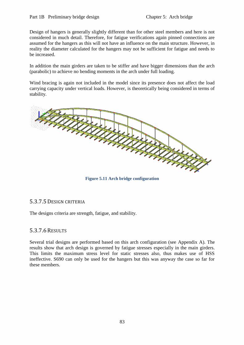
Part 1B Preliminary bridge design Chapter 5: Arch bridge
83
Design of hangers is generally slightly different than for other steel members and here is not
considered in much detail. Therefore, for fatigue verifications again pinned connections are
assumed for the hangers as this will not have an influence on the main structure. However, in
reality the diameter calculated for the hangers may not be sufficient for fatigue and needs to
be increased.
In addition the main girders are taken to be stiffer and have bigger dimensions than the arch
(parabolic) to achieve no bending moments in the arch under full loading.
Wind bracing is again not included in the model since its presence does not affect the load
carrying capacity under vertical loads. However, is theoretically being considered in terms of
stability.
Figure 5.11 Arch bridge configuration
5.3.7.5 DESIGN CRITERIA
The designs criteria are strength, fatigue, and stability.
5.3.7.6 RESULTS
Several trial designs are performed based on this arch configuration (see Appendix A). The
results show that arch design is governed by fatigue stresses especially in the main girders.
This limits the maximum stress level for static stresses also, thus makes use of HSS
ineffective. S690 can only be used for the hangers but this was anyway the case so far for
these members.
Part 1B Preliminary bridge design Chapter 6: Discussion of results
84
6 Results
In Part 1B, three preliminary designs for a single, long span bridge in the Netherlands- the
Schellingwouderbrug-, using high strength steel grade S690 in the heavily loaded members.
The three designs involve a box girder bridge, a warren type truss girder bridge and a tied
arch bridge with vertical hangers. The main design criteria were strength, stability and
fatigue. However, only the governing criteria were investigated for each bridge.
For example, buckling was not mentioned in case of an Arch bridge because it was found
right almost from the beginning that fatigue stresses were high due to large bending moments
in the deck and use of high strength steel was not efficient. Plus the member buckling lengths
were smaller than in the case of the truss while the cross sectional areas were much bigger.
Stiffness was also considered especially in case of the box girder due to the very slender cross
section.
The main results are:
1. It is found that it is generally possible to consider (at least at the preliminary phase) a
box girder so slender using S690 or even S500 for the bottom flange (region with very
high tensile stresses) and with relatively small thicknesses (min thickness= 50 mm for
the bottom flange). However the demands for stiffness and local buckling will
probably not lead to the most economical solution.
2. The extremely slender box section, due to clearance restrictions below the bridge
deck, cannot satisfy the demands mainly for stiffness. The strength was sufficient if
the gross sectional area was effective but the effective area was 60 % reduced due to
local buckling effects (class 4 cross section). The plate thicknesses need to be kept
relatively small to avoid expensive preheating.
3. It is not possible to use a box girder (alone) for the ‘Schellingwouderbrug’ due to
depth limitations. This is already verified by the literature findings, where it was
found that economic L/D ratios for box girders are in the range of 20 to 30. In this
case L/D gives an extremely big value (= 64!) and thus, leads to an uneconomic
solution.
4. Two preliminary designs for the truss bridge have been developed each of which
satisfy the main three design criteria strength, stability and fatigue. Fatigue is not
governing in any truss design.
5. On the other hand, buckling found to be critical in some cases. However, the stresses
are kept at relatively high levels and the cross sectional dimensions relatively small.
6. Thus, use of high strength steel seems to be beneficial and a more detailed design
together with total cost estimations should be considered. Also the use of circular
hollow sections with cast joints is interesting to be investigated. Finally, truss
optimization can potentially lead to an economic and effective bridge design with
high strength steel.
Part 1B Preliminary bridge design Chapter 6: Discussion of results
85
7. Fatigue stresses due to bending are governing the tied arch configuration. The stresses
are kept quite small and the member cross sections need to be increased a lot to keep
fatigue stresses low. This, however, keeps also static stresses much below 400 MPa
and thus it is not proving to be efficient to use high strength steel grades. Explicit
detailing (FEM modeling) together with a more accurate fatigue calculation is
recommended before we can conclude on the unsuitability of the arch bridge in hybrid
construction. However, this was not possible to be included in this study.
8. Preliminary design points towards a truss bridge design for the Schellingwouderbrug.
Apart from the design criteria there are other important issues that need to be
considered in order to determine the suitability of the truss bridge design for the
specific location. Those are erection method, bridge transportation on site and also
maintenance. These practical aspects also determine a big percentage of the total
costs.
6.1 Extra considerations
The ‘Schellingwouderbrug’ is located above a big canal and thus transportation is also
possible from land as from the river. However, erection methods are limited to launching and
lifting since temporary supports would interrupt the boat traffic. For example it is possible
that the whole bridge could be totally prefabricated in its final state (painted etc.), transferred
on site by boat and then lifted up in place with cranes. High strength steels can benefit this
method even more due to low dead weight of steelwork they provide.
The truss bridge can therefore be an interesting solution for the use of high strength steel
grades in case of the ‘Schellingwouderbrug’ leading to an effective and economical design.

Part 2
86
Part 2 Detailed design
In chapter 7 material costs are calculated for several bridge designs based on their self-
weight. The designs are compared and one of them is chosen based not only on material costs
but on total costs consideration.
The chosen design (i.e. hybrid design of a truss bridge) is designed in more detail, in chapter
8. Initially, rectangular hollow section (RHS) members are considered and design of
connections is performed for adequate strength and fatigue. Later on, a hybrid design with
circular hollow section (CHS) members is also developed using the same bridge
configuration. All the bridge designs are made according to European standards.
In addition estimation of cross sectional dimensions and associated costs is attempted for
equivalent designs out of S355 only for both RHS and CHS truss designs.
In chapter 9, material costs are calculated and also total costs are estimated for each hybrid
design (S355, S460 and S690) and their homogeneous equivalents (S355 only). The designs
are compared on a total costs basis. The comparison aims to check whether the hybrid bridge
designs can be more economical than the homogeneous ones.
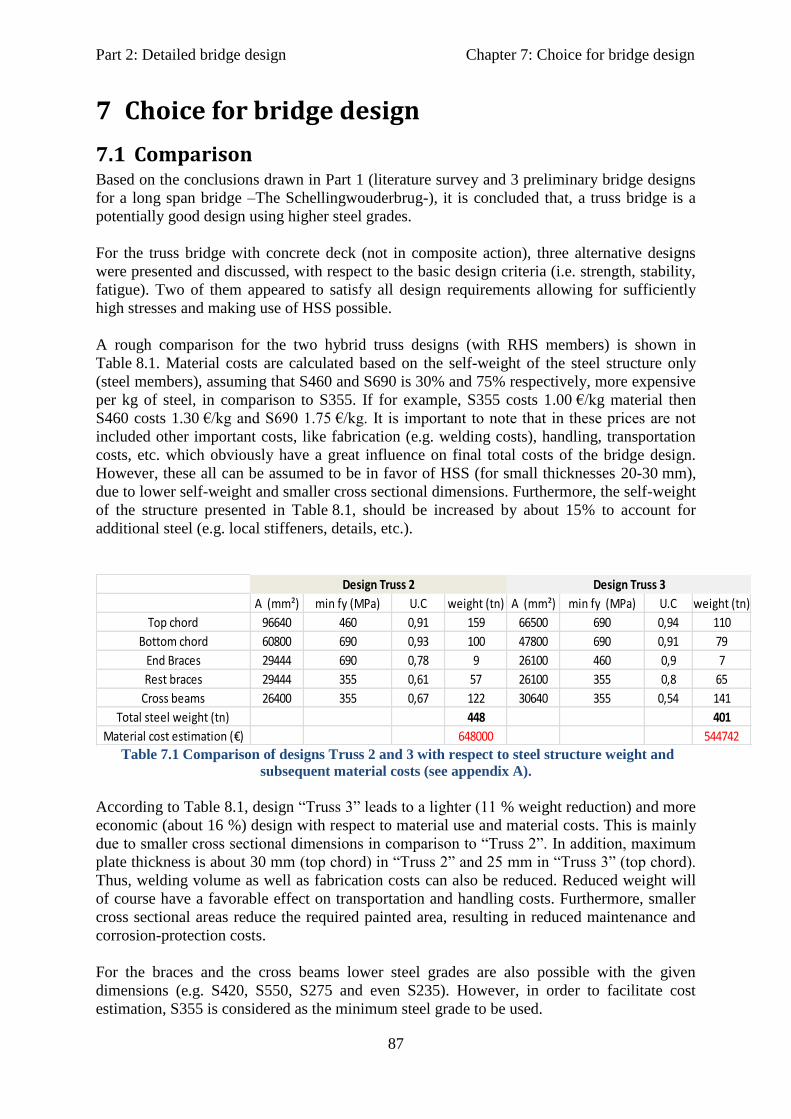
Part 2: Detailed bridge design Chapter 7: Choice for bridge design
87
7 Choice for bridge design
7.1 Comparison Based on the conclusions drawn in Part 1 (literature survey and 3 preliminary bridge designs
for a long span bridge –The Schellingwouderbrug-), it is concluded that, a truss bridge is a
potentially good design using higher steel grades.
For the truss bridge with concrete deck (not in composite action), three alternative designs
were presented and discussed, with respect to the basic design criteria (i.e. strength, stability,
fatigue). Two of them appeared to satisfy all design requirements allowing for sufficiently
high stresses and making use of HSS possible.
A rough comparison for the two hybrid truss designs (with RHS members) is shown in
Table 8.1. Material costs are calculated based on the self-weight of the steel structure only
(steel members), assuming that S460 and S690 is 30% and 75% respectively, more expensive
per kg of steel, in comparison to S355. If for example, S355 costs 1.00 €/kg material then
S460 costs 1.30 €/kg and S690 1.75 €/kg. It is important to note that in these prices are not
included other important costs, like fabrication (e.g. welding costs), handling, transportation
costs, etc. which obviously have a great influence on final total costs of the bridge design.
However, these all can be assumed to be in favor of HSS (for small thicknesses 20-30 mm),
due to lower self-weight and smaller cross sectional dimensions. Furthermore, the self-weight
of the structure presented in Table 8.1, should be increased by about 15% to account for
additional steel (e.g. local stiffeners, details, etc.).
A (mm²) min fy (MPa) U.C weight (tn) A (mm²) min fy (MPa) U.C weight (tn)
Top chord 96640 460 0,91 159 66500 690 0,94 110
Bottom chord 60800 690 0,93 100 47800 690 0,91 79
End Braces 29444 690 0,78 9 26100 460 0,9 7
Rest braces 29444 355 0,61 57 26100 355 0,8 65
Cross beams 26400 355 0,67 122 30640 355 0,54 141
Total steel weight (tn) 448 401
Material cost estimation (€) 648000 544742
Design Truss 3Design Truss 2
Table 7.1 Comparison of designs Truss 2 and 3 with respect to steel structure weight and
subsequent material costs (see appendix A).
According to Table 8.1, design “Truss 3” leads to a lighter (11 % weight reduction) and more
economic (about 16 %) design with respect to material use and material costs. This is mainly
due to smaller cross sectional dimensions in comparison to “Truss 2”. In addition, maximum
plate thickness is about 30 mm (top chord) in “Truss 2” and 25 mm in “Truss 3” (top chord).
Thus, welding volume as well as fabrication costs can also be reduced. Reduced weight will
of course have a favorable effect on transportation and handling costs. Furthermore, smaller
cross sectional areas reduce the required painted area, resulting in reduced maintenance and
corrosion-protection costs.
For the braces and the cross beams lower steel grades are also possible with the given
dimensions (e.g. S420, S550, S275 and even S235). However, in order to facilitate cost
estimation, S355 is considered as the minimum steel grade to be used.
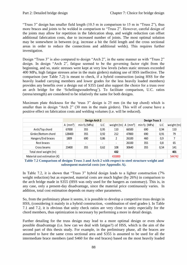
Part 2: Detailed bridge design Chapter 7: Choice for bridge design
88
“Truss 3” design has smaller field length (10.5 m in comparison to 15 m in “Truss 2”), thus
more braces and joints to be welded in comparison to “Truss 2”. However, careful design of
the joints may allow for repetition in the fabrication shop, and weight reduction can offset
additional fabrication costs, due to increased number of joints. The most optimal solution
may be somewhere in between (e.g. increase a bit the field length and the cross sectional
areas in order to reduce the connections and additional welds). This requires further
investigation.
Design “Truss 3” is also compared to design “Arch 2”, in the same manner as with “Truss 2”
design. In design “Arch 2”, fatigue seemed to be the governing factor right from the
beginning, and so, static stresses were kept at very low levels (when static stresses exceeded
400 MPa, high fatigue stresses arise in the main girders) making use of HSS ineffective. The
comparison (see Table 7.2) is meant to check, if a hybrid construction (using HSS for the
heavily loaded carrying members and lower grades for the less heavily loaded members)
provides any benefits over a design out of S355 (and also support the choice for a truss over
an arch bridge for the ‘Schellingwouderbrug’). To facilitate comparison, U.C. ratios
(stress/strength) are considered to be relatively the same for both designs.
Maximum plate thickness for the ‘truss 3” design is 25 mm (in the top chord) which is
smaller than in design “Arch 2” (30 mm in the main girders). This will of course have a
positive effect on fabrication costs and welding volumes (i.e. will be reduced).
A (mm²) min fy (MPa) U.C weight (tn) A (mm²) min fy (MPa) U.C weight (tn)
Arch/Top chord 67000 355 0,95 110 66500 690 0,94 110
Girder/Bottom chord 128400 355 0,92 212 47800 690 0,91 79
Hangers/End braces 1809 690 0,86 2 26100 460 0,9 7
Rest braces - - - - 26100 355 0,8 65
Cross beams 23400 355 0,62 108 30640 355 0,54 141
Total steel weight (tn) 432 401
Material cost estimation (€) 433000 544742
Design Truss 3Design Arch 2
Table 7.2 Comparison of designs Truss 3 and Arch 2 with respect to steel structure weight and
subsequent material costs (see Appendix A).
In Table 7.2, it is shown that “Truss 3” hybrid design leads to a lighter construction (7%
weight reduction) but as expected, material costs are much higher (by 26%) in comparison to
the arch bridge made in S355 (HSS was only used for the hangers as customary). This is, in
any case, only a present-day disadvantage, since the material price continuously varies. In
addition, total cost estimation depends on many other parameters.
So, from the preliminary phase it seems, it is possible to develop a competitive truss design in
HSS, (considering it mainly in a hybrid construction, -combination of steel grades-). In Table
7.1 and 7.2, it is obvious that unity check ratios are very close to unity especially for the
chord members, thus optimization is necessary by performing a more in detail design.
Further detailing for the truss design may lead to a more optimal design or even show
possible disadvantage (i.e. how can we deal with fatigue?) of HSS, which is the aim of the
second part of this thesis study. For example, in the preliminary phase, all the braces are
assumed to have the same cross sectional area and S355 is assumed to be used for all the
intermediate brace members (and S460 for the end braces) based on the most heavily loaded

Part 2: Detailed bridge design Chapter 7: Choice for bridge design
89
brace member (i.e. braces 2 and 3). But in fact, only the braces closer to the supports need to
withstand the higher normal stresses. Therefore, all intermediate braces close to midspan may
be built out of even smaller steel grades. Alternatively, smaller brace cross sections can be
used in truss region around midspan. In that way, material as well as total costs may be
further reduced.
It must be noted that in these trial truss designs it is difficult to apply HSS (S690) in the
braces also due to stability problems. This refers of course especially to the compression
braces, because the member length is rather large and will lead to instability problems.
Furthermore, aesthetical considerations would more likely limit reduction of the cross
sectional dimensions for the tensile braces, also. However, an alternative design (e.g. (much)
smaller brace length or intermediate brace supports) can make use of HSS possible in the
braces also, allowing for smaller cross sections and thus, reducing the overall steel structure
weight even more.
7.2 Final choice
Concluding, it is expected that due to lower dead weight (the difference is rather small but
could be further increased with careful design optimization) of the hybrid truss design
(“Truss 3”) -in comparison to “Truss 2” and “Arch 2” designs- the economic benefits to be
gained in terms of total costs highly offset the higher material costs observed in Table 7.2.
This is based on the estimation that, lower steel self-weight will have an influence on
foundations (e.g. smaller piers may be required), transportation and erection costs, while
smaller cross sectional areas will have a positive effect on maintenance (smaller painted area
required) and fabrication (especially welding) costs, especially in small thicknesses (no
preheating and no special machining equipment).
Thus, design “Truss 3” is chosen for a detailed design, as it seems that can offer further
weight savings and consequent cost benefits in terms of total costs for the
‘Schellingwouderbrug’.
Part 2: Detailed design Chapter 8: Detailed truss design
90
8 Detailed truss bridge design
8.1 General
Detailed design refers to design of joints and connections. Connections have an essential role
on the final decision of member design and cross sectional properties but also on costs.
Especially nowadays, fabrication and labor costs are the most costly part of construction.
Designing, for example, for the lowest bridge weight, does not usually offer the most
economical solution (e.g. extra costs of stiffening very slender plates).
Thus, designing and detailing must be carried out always with respect to feasibility and
constructability.
8.2 Design codes and limitations
The design of connections is done according to European standards EN 1993-1-8 (design of
joints) and EN 1993-1-9 (fatigue design). Additional information for HSS was found in
CIDECT design guides 1 [13], 3 [14] and 8 [16] for design of hollow section joints. The joint
resistances given in these guides apply up to steel grade S355.
For higher strengths it is mentioned that a reduction factor should be applied to all joint
capacity equations, to account for larger deformations (an out-of plane deformation of 0.03b0
of the connecting RHS face, is used as the maximum deformation limit in case of S355, [Lu
et al., 1994]) in case of chord face plastification occurs (thus if another failure mode governs
it is rather conservative).
This reduction factor is proven to be 0.9 (verified by tests, [Liu and Wardenier, 2004]) for
grades up to S460 and recommended to be 0.8 (not verified by tests though) for higher
strengths (e.g. S690)
Both, EC3 and CIDECT design guides, include geometric and material limitations and thus,
their application in case of HSS is considered conservative or even unsuitable in several
cases. For example, in EN 1993-1-9 the fatigue details require that the geometries of the cross
sections are within certain limits, and thus for this truss design they are not applicable.
In this case fatigue calculations should be based on hot spot stress ranges calculating the
stress concentration factors (SCFs) for different joints and for different locations (e.g. toe,
heel etc.).
8.3 Critical truss joints with RHS members
The most critical locations for each member have been found and checked only. A detail is
defined as critical with respect to either its strength capacity or if it appears to be fatigue
sensitive.
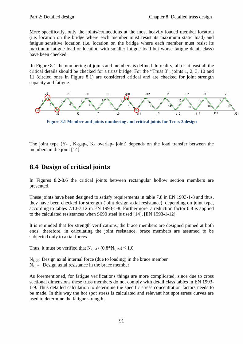
Part 2: Detailed design Chapter 8: Detailed truss design
91
More specifically, only the joints/connections at the most heavily loaded member location
(i.e. location on the bridge where each member must resist its maximum static load) and
fatigue sensitive location (i.e. location on the bridge where each member must resist its
maximum fatigue load or location with smaller fatigue load but worse fatigue detail class)
have been checked.
In Figure 8.1 the numbering of joints and members is defined. In reality, all or at least all the
critical details should be checked for a truss bridge. For the “Truss 3”, joints 1, 2, 3, 10 and
11 (circled ones in Figure 8.1) are considered critical and are checked for joint strength
capacity and fatigue.
Figure 8.1 Member and joints numbering and critical joints for Truss 3 design
The joint type (Y- , K-gap-, K- overlap- joint) depends on the load transfer between the
members in the joint [14].
8.4 Design of critical joints
In Figures 8.2-8.6 the critical joints between rectangular hollow section members are
presented.
These joints have been designed to satisfy requirements in table 7.8 in EN 1993-1-8 and thus,
they have been checked for strength (joint design axial resistance), depending on joint type,
according to tables 7.10-7.12 in EN 1993-1-8. Furthermore, a reduction factor 0.8 is applied
to the calculated resistances when S690 steel is used [14], [EN 1993-1-12].
It is reminded that for strength verifications, the brace members are designed pinned at both
ends; therefore, in calculating the joint resistance, brace members are assumed to be
subjected only to axial forces.
Thus, it must be verified that Ni, Ed / (0.8*Ni, Rd) ≤ 1.0
Ni, Ed: Design axial internal force (due to loading) in the brace member
Ni, Rd: Design axial resistance in the brace member
As forementioned, for fatigue verifications things are more complicated, since due to cross
sectional dimensions these truss members do not comply with detail class tables in EN 1993-
1-9. Thus detailed calculation to determine the specific stress concentration factors needs to
be made. In this way the hot spot stress is calculated and relevant hot spot stress curves are
used to determine the fatigue strength.

Part 2: Detailed design Chapter 8: Detailed truss design
92
Determining the SCFs though requires accurate and detailed modeling which can only be
made with FEM program using plate elements. This could not be done within this thesis
project though since determining the exact SCFs for different joint configurations is a thesis
project by itself.
Nevertheless, using SCFs’ formulas and relevant hot spot stress graphs found in literature
[16], a fatigue check has been performed to estimate the fatigue performance. Finally, the
Miner’s rule is applied to calculate the fatigue damage at each critical location caused by
FLM4 on the bridge.
For more information reference is made to excel sheets for fatigue calculations and Appendix
B.
Joint 1: Connection between bottom chord and end brace member
Figure 8.2 Critical Joint 1 configuration, Y- joint
The end brace is the most heavily loaded compression brace member on the bridge. This joint
is checked for strength (all members) and for fatigue (with respect to the end brace member).
Joint 2: Connection between top chord, end brace and brace 2 members
Figure 8.3 Critical joint 2 configuration, K- gap joint
Joint 2 (J2):
Top chord: 500x 550x 30
End brace: 500x 400x 19
Brace 2: 400x 400x 15
Gap g= 70 mm
Eccentricity e= + 108 mm
θ1= 54°
θ2= 53°
Joint 1 (J1):
Bottom chord: 500x 550x 30
End brace: 500x 400x 19
θ1= 54°

Part 2: Detailed design Chapter 8: Detailed truss design
93
This joint is checked for strength (all members) and for fatigue (with respect to the end brace
member). Brace 2 is the most heavily loaded tension brace member.
Joint 3: Connection between bottom chord, brace 2 and brace 3 members
Figure 8.4 Critical joint 3 configuration, K- overlap joint
Braces 2 and 3 are the most heavily loaded with respect to fatigue at this joint. This joint is
checked for strength (all members) and for fatigue (with respect to the brace member).
Joint 10: Connection between top chord, brace 9 and brace 10 members
Figure 8.5 Critical joint 10 configuration, K- gap joint
This joint is chosen to be checked for strength as the top chord is most heavily loaded here.
Also fatigue strength is checked with respect to the top chord as fatigue stresses are also quite
high in the chord due to FLM4.
Joint 3 (J3):
Bottom chord: 500x 550x 30
Braces 2 and 3: 400x 400x 15
Overlap Ov= 50%
Eccentricity e= -108 mm
θ2= θ3= 53°
Joint 10 (J10):
Top chord: 500x 550x 30
Braces 9 and 10: 400x 400x 15
Gap g= 75 mm
Eccentricity e= +108 mm
θ9= θ10= 53°
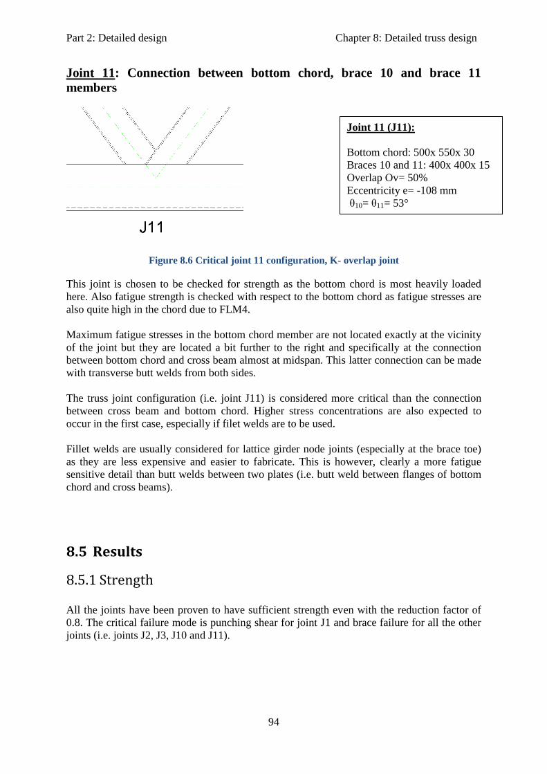
Part 2: Detailed design Chapter 8: Detailed truss design
94
Joint 11: Connection between bottom chord, brace 10 and brace 11
members
Figure 8.6 Critical joint 11 configuration, K- overlap joint
This joint is chosen to be checked for strength as the bottom chord is most heavily loaded
here. Also fatigue strength is checked with respect to the bottom chord as fatigue stresses are
also quite high in the chord due to FLM4.
Maximum fatigue stresses in the bottom chord member are not located exactly at the vicinity
of the joint but they are located a bit further to the right and specifically at the connection
between bottom chord and cross beam almost at midspan. This latter connection can be made
with transverse butt welds from both sides.
The truss joint configuration (i.e. joint J11) is considered more critical than the connection
between cross beam and bottom chord. Higher stress concentrations are also expected to
occur in the first case, especially if filet welds are to be used.
Fillet welds are usually considered for lattice girder node joints (especially at the brace toe)
as they are less expensive and easier to fabricate. This is however, clearly a more fatigue
sensitive detail than butt welds between two plates (i.e. butt weld between flanges of bottom
chord and cross beams).
8.5 Results
8.5.1 Strength
All the joints have been proven to have sufficient strength even with the reduction factor of
0.8. The critical failure mode is punching shear for joint J1 and brace failure for all the other
joints (i.e. joints J2, J3, J10 and J11).
Joint 11 (J11):
Bottom chord: 500x 550x 30
Braces 10 and 11: 400x 400x 15
Overlap Ov= 50%
Eccentricity e= -108 mm
θ10= θ11= 53°
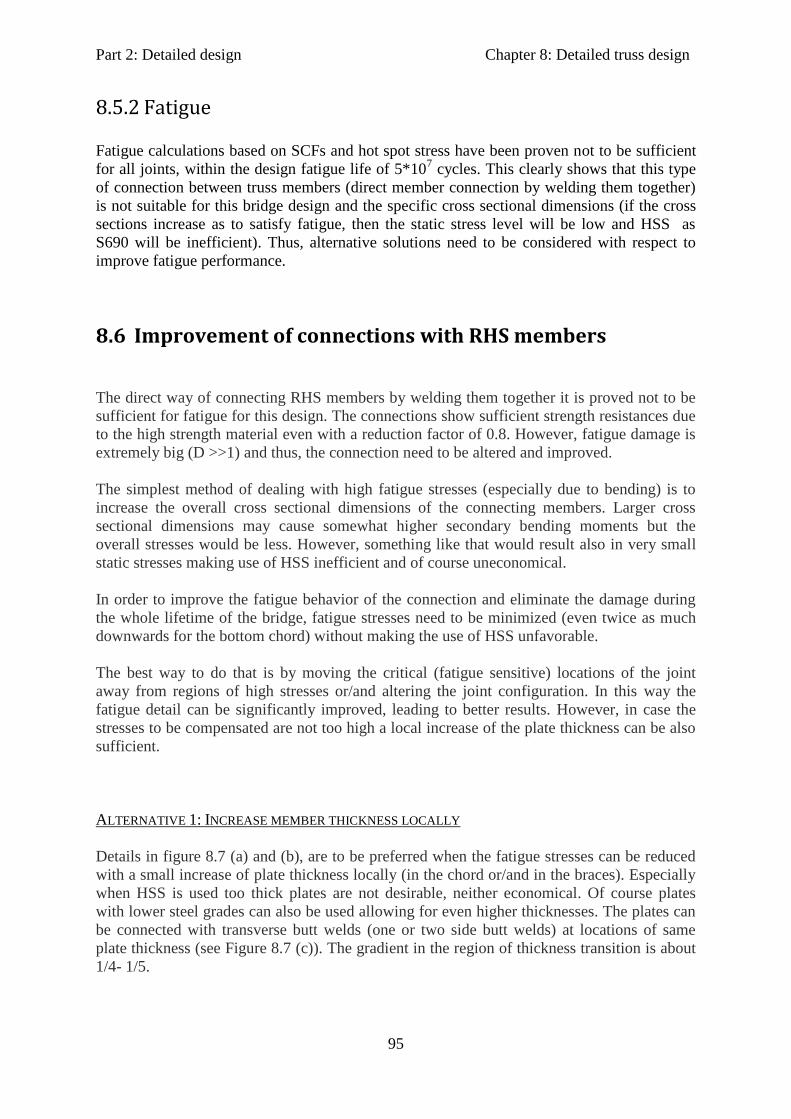
Part 2: Detailed design Chapter 8: Detailed truss design
95
8.5.2 Fatigue
Fatigue calculations based on SCFs and hot spot stress have been proven not to be sufficient
for all joints, within the design fatigue life of 5*107 cycles. This clearly shows that this type
of connection between truss members (direct member connection by welding them together)
is not suitable for this bridge design and the specific cross sectional dimensions (if the cross
sections increase as to satisfy fatigue, then the static stress level will be low and HSS as
S690 will be inefficient). Thus, alternative solutions need to be considered with respect to
improve fatigue performance.
8.6 Improvement of connections with RHS members
The direct way of connecting RHS members by welding them together it is proved not to be
sufficient for fatigue for this design. The connections show sufficient strength resistances due
to the high strength material even with a reduction factor of 0.8. However, fatigue damage is
extremely big (D >>1) and thus, the connection need to be altered and improved.
The simplest method of dealing with high fatigue stresses (especially due to bending) is to
increase the overall cross sectional dimensions of the connecting members. Larger cross
sectional dimensions may cause somewhat higher secondary bending moments but the
overall stresses would be less. However, something like that would result also in very small
static stresses making use of HSS inefficient and of course uneconomical.
In order to improve the fatigue behavior of the connection and eliminate the damage during
the whole lifetime of the bridge, fatigue stresses need to be minimized (even twice as much
downwards for the bottom chord) without making the use of HSS unfavorable.
The best way to do that is by moving the critical (fatigue sensitive) locations of the joint
away from regions of high stresses or/and altering the joint configuration. In this way the
fatigue detail can be significantly improved, leading to better results. However, in case the
stresses to be compensated are not too high a local increase of the plate thickness can be also
sufficient.
ALTERNATIVE 1: INCREASE MEMBER THICKNESS LOCALLY
Details in figure 8.7 (a) and (b), are to be preferred when the fatigue stresses can be reduced
with a small increase of plate thickness locally (in the chord or/and in the braces). Especially
when HSS is used too thick plates are not desirable, neither economical. Of course plates
with lower steel grades can also be used allowing for even higher thicknesses. The plates can
be connected with transverse butt welds (one or two side butt welds) at locations of same
plate thickness (see Figure 8.7 (c)). The gradient in the region of thickness transition is about
1/4- 1/5.

Part 2: Detailed design Chapter 8: Detailed truss design
96
Figure 8.7 Locally thicker plates (a) when both braces and chord members are critical, (b)
when the fatigue sensitive detail is located in the chord member. Plates welded together with one
(or two if possible) side transverse butt welds.
This detail has the advantage that it thickens the plates in the critical locations, thus reducing
the fatigue stresses (but also the static stresses) locally and the stress concentration factors
may be lower especially in the chord member due to lower τ- ratios (=ti/t0). In addition, the
one or two side butt weld that connects the plate is positioned further than the thickness
gradient at a location of equal thicknesses. This requires that extra material need to be lost
(removed). The final result, however, is a better detail for fatigue, since it is outside the very
high stress region and the influence of the thickness gradient is negligible.
The main disadvantage is that the detail configuration is not altered, thus the critical
locations and the complexity of the joint behavior remains the same, and in addition extra
critical locations (butt welds) need to be checked (although probably not governing).
In case of S690 is recommended that the plate thickness can be kept at rather low values (at
about 30 mm) to avoid extra costs from expensive preheating. In that case it may be better to
use a lower steel grade to compensate with the extra costs. Of course for very thick plates, the
yield stress decreases after a certain thickness (e.g. after t=50 mm for S690) and also through
thickness properties decrease. That should be taken into account, if relevant.
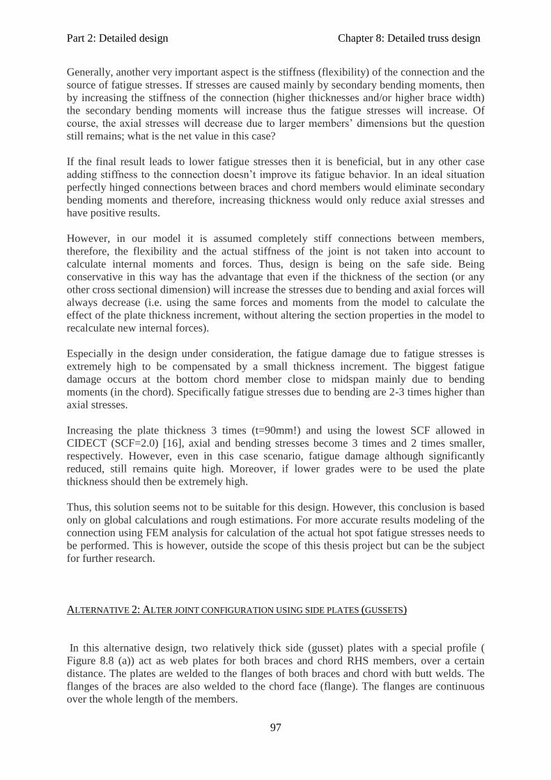
Part 2: Detailed design Chapter 8: Detailed truss design
97
Generally, another very important aspect is the stiffness (flexibility) of the connection and the
source of fatigue stresses. If stresses are caused mainly by secondary bending moments, then
by increasing the stiffness of the connection (higher thicknesses and/or higher brace width)
the secondary bending moments will increase thus the fatigue stresses will increase. Of
course, the axial stresses will decrease due to larger members’ dimensions but the question
still remains; what is the net value in this case?
If the final result leads to lower fatigue stresses then it is beneficial, but in any other case
adding stiffness to the connection doesn’t improve its fatigue behavior. In an ideal situation
perfectly hinged connections between braces and chord members would eliminate secondary
bending moments and therefore, increasing thickness would only reduce axial stresses and
have positive results.
However, in our model it is assumed completely stiff connections between members,
therefore, the flexibility and the actual stiffness of the joint is not taken into account to
calculate internal moments and forces. Thus, design is being on the safe side. Being
conservative in this way has the advantage that even if the thickness of the section (or any
other cross sectional dimension) will increase the stresses due to bending and axial forces will
always decrease (i.e. using the same forces and moments from the model to calculate the
effect of the plate thickness increment, without altering the section properties in the model to
recalculate new internal forces).
Especially in the design under consideration, the fatigue damage due to fatigue stresses is
extremely high to be compensated by a small thickness increment. The biggest fatigue
damage occurs at the bottom chord member close to midspan mainly due to bending
moments (in the chord). Specifically fatigue stresses due to bending are 2-3 times higher than
axial stresses.
Increasing the plate thickness 3 times (t=90mm!) and using the lowest SCF allowed in
CIDECT (SCF=2.0) [16], axial and bending stresses become 3 times and 2 times smaller,
respectively. However, even in this case scenario, fatigue damage although significantly
reduced, still remains quite high. Moreover, if lower grades were to be used the plate
thickness should then be extremely high.
Thus, this solution seems not to be suitable for this design. However, this conclusion is based
only on global calculations and rough estimations. For more accurate results modeling of the
connection using FEM analysis for calculation of the actual hot spot fatigue stresses needs to
be performed. This is however, outside the scope of this thesis project but can be the subject
for further research.
ALTERNATIVE 2: ALTER JOINT CONFIGURATION USING SIDE PLATES (GUSSETS)
In this alternative design, two relatively thick side (gusset) plates with a special profile (
Figure 8.8 (a)) act as web plates for both braces and chord RHS members, over a certain
distance. The plates are welded to the flanges of both braces and chord with butt welds. The
flanges of the braces are also welded to the chord face (flange). The flanges are continuous
over the whole length of the members.

Part 2: Detailed design Chapter 8: Detailed truss design
98
Figure 8.8 Improved connection with thick side gusset plates. (a) blue shaded area represents
the side plate profile, (b) cross sectional view, (c) brace and chord flange connection and
possible fatigue critical locations.
The main idea behind this solution is to make the fatigue sensitive details of RHS members
(Figure 8.8 (c), location 5) non critical, by alternating the joint configuration and more
specifically, the way the load is transferred from the braces to the chords. That is similar to
the philosophy behind casting in circular hollow sections.
The load from the braces is assumed to pass through the welds (brace to plate connection-
location 1 in Figure 8.8 (c)) to the thick side plates, and then from the plates to the chord
member (through plate to chord transverse butt welds- location 2 in Figure 8.8 (c)).
A limitation of this design is that brace and chord members should have equal widths to make
the welding of the plates feasible. Again, the connection between the plates, with thickness
transition from one plate to the other, is similar to that in Figure 8.7 (c).
The flanges of the brace members are welded also to the chord face (e.g. location 5 in Figure
8.8 (c)) in order to shield the joint from the environment (better durability, less maintenance
demand). However, at this location is expected that low stresses will occur, since the main
load transfer is being made through the plates and not through the chord face.

Part 2: Detailed design Chapter 8: Detailed truss design
99
The distance for which this plate is extended over the braces and chord at the joint location,
depends on the force and moment distribution in the truss model. The concept is to choose
the location of the connecting butt welds being at a less severe location (with lower stresses),
away from the joint.
The advantage of doing this is that, at these locations only nominal (and lower) stresses in the
members can be taken into account, and the fatigue life can be calculated by using the
relevant S-N curve according to detail classification in EN1993-1-9.
Thus, changing from an unfavorable detail (lattice girder joint) to a more favorable one
(plates welded together) and also moving to a region with much lower stresses, results in a
much improved fatigue behavior for these connections.
For fatigue check the critical positions are now located mainly on the ends of the side plate
(see Figure 8.8 (c)) where the load is transferred from and towards adjacent members through
the butt welds. In the side plate localized stress concentrations may occur at the curved part
(location 4) or at “passing through” welds (e.g. where chord flange is butt welded to the side
plate). The actual level of stress concentration can only be determined by FEM analysis. The
overall stress distribution though will be rather uniform.
In any case, the stress peaks can be minimalized by adjusting the radius (i.e. higher radius
creates smoother shapes and thus lower stress concentration) and/or increasing plate
thickness. Thus, fatigue check can be satisfied.
Since the brace member is connected to the flange of the bottom chord (Figure 8.8 (c),
location 5), all the critical for fatigue details remain in the joint. However, they are expected
not to be governing due to much lower stresses at this location in comparison to locations 1
and 2.
To avoid completely dealing with these details the design of the connection may be further
improved.
A possibility is to stop the brace member at the connection with the side plates (Figure 8.9
(a)). However, high stress peaks will occur at the corners of the end bottom plate of the brace,
due to higher stiffness at this location (Figure 8.9 (b)). These peaks can be significant, and
thus critical for fatigue.
Therefore, a further improvement could be to profile the brace at the connection with the side
plates as shown in Figure 8.9 (c). In this way the stress distribution will be more uniform due
to the plate curvature. An extra thin plate can be added in the brace just to close it from the
environment.
This solution has the advantage that we avoid the connection between the brace flange to the
chord face. However the space between the braces, the chord and the two side plates remain
open from one side, thus additional maintenance issues occur. The area should be protected
(e.g. painted) and accessible for regular inspections and future repair, if necessary.
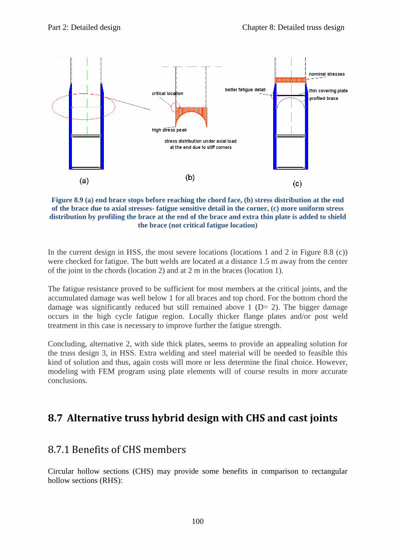
Part 2: Detailed design Chapter 8: Detailed truss design
100
Figure 8.9 (a) end brace stops before reaching the chord face, (b) stress distribution at the end
of the brace due to axial stresses- fatigue sensitive detail in the corner, (c) more uniform stress
distribution by profiling the brace at the end of the brace and extra thin plate is added to shield
the brace (not critical fatigue location)
In the current design in HSS, the most severe locations (locations 1 and 2 in Figure 8.8 (c))
were checked for fatigue. The butt welds are located at a distance 1.5 m away from the center
of the joint in the chords (location 2) and at 2 m in the braces (location 1).
The fatigue resistance proved to be sufficient for most members at the critical joints, and the
accumulated damage was well below 1 for all braces and top chord. For the bottom chord the
damage was significantly reduced but still remained above 1 (D= 2). The bigger damage
occurs in the high cycle fatigue region. Locally thicker flange plates and/or post weld
treatment in this case is necessary to improve further the fatigue strength.
Concluding, alternative 2, with side thick plates, seems to provide an appealing solution for
the truss design 3, in HSS. Extra welding and steel material will be needed to feasible this
kind of solution and thus, again costs will more or less determine the final choice. However,
modeling with FEM program using plate elements will of course results in more accurate
conclusions.
8.7 Alternative truss hybrid design with CHS and cast joints
8.7.1 Benefits of CHS members
Circular hollow sections (CHS) may provide some benefits in comparison to rectangular
hollow sections (RHS):

Part 2: Detailed design Chapter 8: Detailed truss design
101
- Circular hollow sections (CHS) offer a pleasing shape, although, specialized profiling is
needed when joining circular shapes together.
- For CHS a single longitudinal weld is required (in contrast, four welds for RHS members)
reducing the overall weld volume.
- CHS members are standardized in rather large dimensions (e.g. maximum available is
660x50 for S355 steel grade) and can be ordered from stock, directly, thus costs are reduced
significantly.
- Their (smooth) circular shape allows for more uniform stress distribution (i.e. no stiff
corners).
- Fatigue detail category, according to EN 1993-1-9, for CHS lattice joints is higher than for
RHS sections (i.e. fatigue class 90 and 71, respectively), leading to better fatigue
performance.
- The design of connections (especially for fatigue) can be improved significantly by using cast
joints. Cast joints are not available in case of RHS members.
- Slenderness ratios (D/t) are far more relaxed than in case of RHS (c/t), allowing for more
slender cross sections. This is quite beneficial in case of HSS where due to higher yield
strength (fy), these ratios limits become even smaller.
- The overall cross sectional dimensions can be reduced.
8.7.2 Members and dimensions
A truss design with circular hollow section members (CHS) has been developed for the
‘Schellingwouderbrug’. The overall bridge layout is not changed, but only the cross sectional
shape and the type of joints.
More specifically for the chord members standard tubular members are used with dimensions
610x32. For all the braces again standard sections are chosen with dimensions 457x20. CHS
truss members have been verified for strength and stability as in case of Truss 3 design with
RHS members. For more information in cross sectional properties and for strength and
stability checks reference is made to Appendix B.
The cross beams are again welded I –sections. Their dimensions are not altered to facilitate
comparison and since they are sufficient for strength (U.C =0.91).
8.7.3 Cast design
For the connections casted joints are considered. They are readily available also for S690
steel grades. These joints can be properly designed to have adequate static and fatigue
strength and optimal shape with the help of a FEM program. Butt welds can connect the cast
Part 2: Detailed design Chapter 8: Detailed truss design
102
steel to the member high strength steel. This is a relatively good fatigue detail and in addition
as in the case of RHS with gusset plates the welds are positioned at locations of lower
stresses and stress concentrations.
The static strength of the connection is ensured by making the cast joint at least as strong as
the most heavily loaded member.
Fatigue strength can also be ensured by optimal and smooth shape of the casting and careful
variations of local thicknesses. Thus, the locations which may be critical and need to be
checked for fatigue are the butt welds at the connection of the casting to the truss members
(similar to the case of RHS sections with gusset plates).
8.7.4 Costs
As the same brace member cross section is used all over the bridge repetition is allowed,
which will require even a single mold for casted steel. This fact in comparison to
standardized member sections will have a big influence on fabrication costs. However, plate
thicknesses are somewhat bigger than in case of RHS design which may lead to increasing
welding volume. On the other hand overall exposed area is smaller. Thus, maintenance cost
reduction may be expected.
8.8 Truss design using S355 steel grade only
For sake of general comparison only, equivalent designs assuming steel grade S355 for all
truss members (chords, braces) are considered in case of: 1) truss bridge with RHS members
and gusset plates, and 2) truss bridge design with CHS members and cast joints.
Two sub-alternatives are considered for “all in S355” designs. Either a) increase only the
plate thickness maintaining the other cross sectional dimensions (i.e. diameter, width, and
height) constant or, b) increase the overall cross sectional dimensions keeping the plate
thicknesses constant.
The scope of this is to estimate the possible benefits that a hybrid bridge construction may
offer by comparing plate thicknesses, cross sectional dimensions and dead bridge weight for
hybrid designs and designs in S355.
It is really important however, to make clear that this is only for obtaining a general feeling
and not to compare absolute values. It would be more accurate to create a totally new design
out of S355 steel grade (e.g. different truss height and/or field length, or even totally different
bridge type etc.), and then compare the results. This is not possible, though, due to time
limitations.
Part 2: Detailed design Chapter 8: Detailed truss design
103
However, it is also reminded that in chapter 7 an arch bridge design out of S355 and a hybrid
truss bridge using HSS S690 for the chord members (Truss 3) were compared leading to a
choice for the hybrid truss bridge, mainly due to lower bridge weight.
As it is expected, the required dimensions for the chord members, in case S355 is to be used
only, are almost double in comparison to S690 chord members (see also Table 9.2 and 9.4).
The changes for the braces and cross beams are less apparent as they were already designed
by assuming steel grade S355.

Part 2: Detailed design Chapter 9: Costs estimation
104
9 Total costs estimation
9.1 Final truss bridge designs
In this chapter four truss designs developed for the ‘Schellingwouderbrug’, are compared
mainly on a costs basis by calculating material costs and estimating total costs. Similar unity
check ratios are chosen for each member in different designs to make the comparison as
accurate as possible.
The aim of this comparison is to conclude on the most cost effective design for the
‘Schellingwouderbrug’ and thus check if a hybrid construction provides more benefits.
These designs are:
a) 1. Hybrid truss design with rectangular hollow sections (RHS) members. Connections
with high strength steel side (gusset) plates are assumed.
2. An equivalent to the previous one, but “all in S355” truss design (with RHS).
b) 1. Hybrid truss design with circular hollow sections (CHS) members. Connections
with high strength steel castings are assumed.
2. An equivalent to the previous one, but “all in S355” truss design (with CHS).
It must be noted that the “all in S355” design in both cases (i.e. for RHS and CHS designs)
are based on an estimation of required dimensions or plate thicknesses in order to obtain a
structurally safe design for the reference bridge.
This is based only on strength and stability checks, while for fatigue they are expected to be
more than sufficient due to significantly bigger cross sectional dimensions, and thus lower
fatigue stress levels.
However, this only serves for an estimation of benefits that HSS can offer due to reduced
dimensions and dead weight, when designing on the same basis (i.e. assume given bridge
geometry, length, width, height, field length, brace angles etc.).
This does not, in any case, considered to lead to the most cost effective design made in S355
for the ‘Schellingwouderbrug’.
9.2 Designs comparison on a cost basis
9.2.1 Material costs
By the term “material costs” it is meant that these are costs calculated based on bridge steel
dead weight and include the self-weight of the steel members (i.e. chords, braces, cross
beams) together with an extra 15% to account for welding consumables and extra steel
Part 2: Detailed design Chapter 9: Costs estimation
105
material on the bridge (e.g. wind braces, stiffening plates, etc.). For all designs and for all
truss members (braces, chords) and cross beams, the following have been determined and
presented in tables for direct comparison:
Cross sectional area A (mm2)
Minimum yield strength fy (MPa) depending on the material used in each member
Unity check ratios (U.C), especially for the truss members, are chosen as close as
possible, for each member and at different designs, to make the comparison as
accurate as possible.
Steel members dead weight (tn) according to the formula:
Where,
ni: total number of member i on the bridge
Ai: cross sectional area (mm2) of member i
γ: steel density (= 78.5 kN/m3)
Li: length (m) of member i
Maximum plate thickness t (mm) per member (has important influence on welding
volume required)
Required painting area (mm2) –assuming, conservatively, that the whole external
surface of the member needs to be painted-, is calculated based on the formulas:
For RHS sections:
For CHS sections:
For cross beams:
Where,
ni: total number of member i on the bridge
hi: height (mm) of member i
bi: width (mm) of member i
Di: diameter (mm) of member i
Li: length (mm) of member i
tf: flange thickness (mm) of cross beam i
The painting area gives an indication on corrosion protection costs needed to satisfy
maintenance requirements.
In the tables, in order to determine material costs, the gusset plates as well as the cast
joints in the CHS design are accounted for assuming an additional 10-15 % steel dead
weight increment in the total bridge steel dead weight.
ni*(Ai* 10-6
* γ* Li)/10
ni* (2*(hi +bi))*Li
ni*2*π*(Di/2)*Li
ni*(2*bi+4*tf+(hi-2*tf))*Li
Part 2: Detailed design Chapter 9: Costs estimation
106
Although, the exact dimensions of the gusset plates are not known, their minimum required
plate thickness (based on the most heavily loaded members and assuming, conservatively,
constant gusset plate thickness in all joints) has been calculated according to the formulas
given below (see also Figures 8.8 and 8.9):
- At the connections to the chord members: min tplate, gusset = (N0/2)/ (fy, gplate *h0),
and A plate, gusset = h0 * tplate, gusset, per plate.
- At the connections to the brace members: min tplate, gusset = (Ni/2)/ (fy, gplate *bi),
and A plate, gusset = b0 * tplate, gusset, per plate.
Two gusset plates, acting locally as members web plates are assumed in each joint.
In the hybrid designs high strength steel (i.e. S690) is assumed for the gusset plates, as used
for the chord members, also. In the equivalent “all in S355” truss designs with RHS
members, S355 is of course also assumed for the gusset plates.
Considering the maximum normal forces in the members, similar minimum plate thicknesses
as for the gusset plates, are expected to be required for the castings in design with CHS
members at the ends of the casting plates. In this case, however, the thickness will more
likely vary, being thicker in the middle of the casting than at the ends, for more optimum
structural and fatigue behavior of the joint. Thus the actual thickness(es) can only be
determined using a finite element model.
Finally, the self-weight of the concrete deck (normal weight concrete deck of 240 mm
thickness is assumed for all bridge designs) is not added directly to the calculated value of the
total bridge (steel) dead weight (based on steel members, welds, stiffening plates, etc.), as it
does not influence the difference between the resulting values (see Tables 9.1-9.6) for costs
comparison.
However, the concrete deck has an influence on the value of the final bridge dead weight in
the sense that it has been applied as a load on the bridge (i.e. directly on the cross beams).
Therefore, it has been taken into account when calculating the required steel members
dimensions and thus their self-weight.
Bridge steel material costs (i.e. costs calculated for the dead weight of the main steel
structure- self weight of steel members plus an extra 15% for connections and
additional steel-) are calculated assuming that currently, these material values (for
base steel material and welding consumables) are available:
S355: 1.00 €/ kg (1.00*103€/ton)
S460: 1.30 €/ kg (1.30*103€/ton)
S690: 1.75 €/ kg (1.75*103€/ton)

Part 2: Detailed design Chapter 9: Costs estimation
107
Table 9.1 Hybrid truss design with RHS members and additional gusset plates at the
connections
Member Dimensions (mm) A (mm²) min fy (MPa) U.C weight (tn) classification max tplate(*)
(mm) Apaint, req (mm²)
Top chord 500x550x30 59400 690 0,95 98 class 1 30 4,41E+08
Bottom chord 500x550, tf=30,tw= 20 49600 690 0,88 82 class 1 30 4,41E+08
End braces 500x400x16 27776 460 0,89 8 class 3 16 6,30E+07
Rest braces 500x400x16 27776 355 0,86 69 class 2 16 5,67E+08
I-cross beams B=300,H=550,tf=20,tw=15 19650 355 0,62 91 class 1 20 6,98E+08
Total(**)
347 Total 2,21E+09
484
575
Hybrid design with RHS members and gusset plates
Costs (10³ Euros)with welds and gusset plates
steel members only
(*)
For gusset plates a minimum required plate thickness is estimated (per plate) at the connections
with the truss members. For each gusset plate the min thickness is 15 mm and 32 mm for connections
with the braces and the chords, respectively. Thus, for each gusset plate the min thickness is 32 mm
assuming the same thickness for the whole plate. (**)
An additional 15 % of this value should be considered to account for gusset plates, additional steel
(e.g. wind bracings) and welds. For this value, high strength steel grade S690 is conservatively
assumed for material cost estimation.
Table 9.2 Equivalent “all in S355” truss design with RHS members and gusset plates at the
connections
Member Dimensions (mm) A (mm²) min fy (MPa) U.C weight (tn) classification max tplate(*) (mm) Apaint, req (mm²)
Top chord 500x550x60 111600 355 0,98 184 class 1 60 4,41E+08
Bottom chord 500x550x60 111600 355 0,87 184 class 1 60 4,41E+08
End braces 500x400x20 34400 355 0,91 9 class 2 20 6,30E+07
Rest braces 500x400x18 31104 355 0,81 77 class 2 18 5,67E+08
I-cross beams B=300,H=550,tf=30,tw=15 25350 355 0,71 117 class 1 30 6,98E+08
Total (**)571 Total 2,21E+09
571
657
Member Dimensions (mm) A (mm²) min fy (MPa) U.C weight (tn) classification max tplate (mm) Apaint, req (mm²)
Top chord 900x800x30 98400 355 0,92 162 class 2 30 7,14E+08
Bottom chord 900x900x30 95000 355 0,88 157 class 1 30 7,56E+08
End braces 500x400x19 32380 355 0,85 9 class 2 16 7,00E+07
Rest braces 500x400x16 27776 355 0,83 69 class 2 16 5,67E+08
I-cross beams B=300,H=700,tf=20,tw=15 21900 355 0,88 101 class 1 20 7,86E+08
Total (**)497 Total 2,89E+09
497
572Costs (10³ Euros)
steel members only
with welds and gusset plates
All in S355 truss design with RHS members and gusset plates
a) Only member(s) plate thickness is increased
b) Other cross sectional dimensions (height, width) are increased
Costs (10³ Euros)steel members only
with welds and gusset plates
(*)
For gusset plates a minimum required plate thickness is estimated (per plate) at the connections
with the truss members. Each gusset plate has minimum required thickness 30 mm and 60 mm for
connections with the braces and the chords, respectively. Thus, for each gusset plate the min thickness
is 60 mm assuming the same thickness for the whole plate. (**)
An additional 15 % of this value should be considered to account for gusset plates, additional steel
(e.g. wind bracings) and welding material. For this value, normal steel grade S355 is assumed for
material cost estimation

Part 2: Detailed design Chapter 9: Costs estimation
108
Table 9.3 Hybrid truss design with (standardized) CHS members and cast joints
Member Dimensions (mm) A (mm²) min fy (MPa) U.C weight (tn) classification max tplate(*) (mm) Apaint, req (mm²)
Top chord 610x32 58095 690 0,97 96 class 2 32 4,02E+08
Bottom chord 610x32 58095 690 0,81 96 class 2 32 4,02E+08
End braces 457x20 27452 460 0,92 8 class 2 20 5,02E+07
Rest braces 457x20 27452 355 0,85 68 class 2 20 4,52E+08
I-cross beams B=300,H=610,tf=25,tw=15 23400 355 0,76 108 25 7,34E+08
Total (**)375 Total 2,04E+09
521
619
Hybrid design with CHS members and cast joints
Costs (10³ Euros)steel members only
with welds and castings
(*)
For casting, the plate thickness may vary. The minimum cast thickness cannot be lower than 20 and
32 mm at the connections with the brace and chords respectively. (**)
An additional 15 % of this value should be considered to account for cast joints, additional steel
(e.g. wind bracings) and welds. For this value, high strength steel grade S690 is conservatively
assumed for material cost estimation.
Table 9.4 Equivalent “all in S355” truss design with CHS members and cast joints
Member Dimensions (mm) A (mm²) min fy (MPa) U.C weight (tn) classification max tplate(*)
(mm) Apaint, req (mm²)
Top chord 610x65 111600 355 0,97 184 class 1 65 4,02E+08
Bottom chord 610x65 111600 355 0,91 184 class 1 65 4,02E+08
End braces 457x25 34400 355 0,97 9 class 2 25 5,02E+07
Rest braces 457x20 31104 355 0,91 77 class 2 20 4,52E+08
I-cross beams B=300,H=610,tf=25,tw=15 23400 355 0,71 108 class 1 25 7,39E+08
Total (**)562 Total 2,05E+09
562
646
Member Dimensions (mm) A (mm²) min fy (MPa) U.C weight (tn) classification max tplate (mm) Apaint, req (mm²)
Top chord 1000x32 97294 355 0,94 160 class 2 32 6,60E+08
Bottom chord 1100x32 107350 355 0,89 177 class 1 32 7,26E+08
End braces 559x20 33900 355 0,85 9 class 2 20 6,15E+07
Rest braces 457x20 27452 355 0,81 68 class 2 20 4,52E+08
I-cross beams B=300,H=610,tf=25,tw=15 23400 355 0,77 108 class 1 25 7,39E+08
Total (**)522 Total 2,64E+09
522
601Costs (10³ Euros)
steel members only
with welds and castings
All in S355 truss design with CHS members and cast joints
a) Only member(s) plate thickness is increased
b) Other cross sectional dimensions (diameter,cross beam height) are increased
Costs (10³ Euros)steel members only
with welds and castings
(*)
For casting, the plate thickness may vary. The minimum cast thickness cannot be lower than 25 and
65 mm at the connections with the brace and chords respectively. (**)
An additional 15 % of this value should be considered to account for cast joints, additional steel
(e.g. wind bracings) and welds. For this value, normal steel grade S355 is assumed for material cost
estimation.
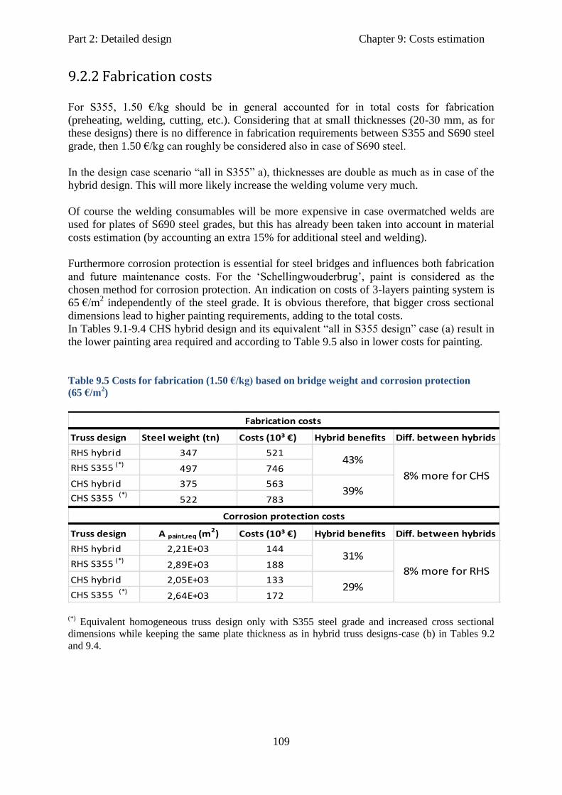
Part 2: Detailed design Chapter 9: Costs estimation
109
9.2.2 Fabrication costs
For S355, 1.50 €/kg should be in general accounted for in total costs for fabrication
(preheating, welding, cutting, etc.). Considering that at small thicknesses (20-30 mm, as for
these designs) there is no difference in fabrication requirements between S355 and S690 steel
grade, then 1.50 €/kg can roughly be considered also in case of S690 steel.
In the design case scenario “all in S355” a), thicknesses are double as much as in case of the
hybrid design. This will more likely increase the welding volume very much.
Of course the welding consumables will be more expensive in case overmatched welds are
used for plates of S690 steel grades, but this has already been taken into account in material
costs estimation (by accounting an extra 15% for additional steel and welding).
Furthermore corrosion protection is essential for steel bridges and influences both fabrication
and future maintenance costs. For the ‘Schellingwouderbrug’, paint is considered as the
chosen method for corrosion protection. An indication on costs of 3-layers painting system is
65 €/m2 independently of the steel grade. It is obvious therefore, that bigger cross sectional
dimensions lead to higher painting requirements, adding to the total costs.
In Tables 9.1-9.4 CHS hybrid design and its equivalent “all in S355 design” case (a) result in
the lower painting area required and according to Table 9.5 also in lower costs for painting.
Table 9.5 Costs for fabrication (1.50 €/kg) based on bridge weight and corrosion protection
(65 €/m2)
Truss design Steel weight (tn) Costs (10³ €) Hybrid benefits Diff. between hybrids
RHS hybrid 347 521
RHS S355 (*)497 746
CHS hybrid 375 563
CHS S355 (*)522 783
Truss design A paint,req (m2) Costs (10³ €) Hybrid benefits Diff. between hybrids
RHS hybrid 2,21E+03 144
RHS S355 (*)2,89E+03 188
CHS hybrid 2,05E+03 133
CHS S355 (*)2,64E+03 172
29%
8% more for CHS
8% more for RHS
Fabrication costs
Corrosion protection costs
43%
39%
31%
(*)
Equivalent homogeneous truss design only with S355 steel grade and increased cross sectional
dimensions while keeping the same plate thickness as in hybrid truss designs-case (b) in Tables 9.2
and 9.4.

Part 2: Detailed design Chapter 9: Costs estimation
110
9.2.3 Transportation costs
In general, transportation costs are influenced by the method (water, land), vehicle type and
capacity and delivery schedule and timetables. Transportation through the land or through the
sea is possible for the ‘Schellingwouderbrug’. Due to the bridge dimensions (geometry) and
its location, the whole bridge is possible to be completely prefabricated and then transferred
as one piece to the site, on special boats. This is the same for all designs as the bridge
geometry remains unaltered. However, costs for handling and lifting at the fabrication shop
may be less for the hybrid designs due to lower weight.
9.2.4 Erection costs
Erection method influences the lifting and handling equipment necessary (e.g. types and
number of cranes). This is of course directly related to the weight of the components or the
whole bridge (if it is going to be lifted in one piece) to be lifted and their cross sectional
dimensions.
As an indication, the cost for cranes are 10000 €/crane/day. Of course in case cranes with
smaller lifting capacity is needed due to smaller bridge weight the price will be much lower.
The lifting capacity depends on the type of crane and if (and how much) they are inclined
during lifting operation. Generally, floating cranes have larger lifting capacity than land
cranes as they can be built bigger and allow for a bigger counterweight at the back.
For the ‘Schellingwouderbrug’ more likely 2 floating cranes will be necessary per day for one
to two days for all designs. However, their lifting capacity (and thus costs) depends on the
bridge dead weight. Thus, it can be expected that both hybrid designs are more economical
due to significant differences in dead weight in comparison to ‘all in S355’ designs.
9.2.5 Maintenance costs
Inspection, maintenance and possible repairs have an important share in total costs during the
lifetime of a bridge. Corrosion protection is already being considered in section 9.2.2 to be in
favor of the hybrid designs due to smaller cross sectional dimensions.
In addition if a more expensive and of higher quality paint is applied, this may reduce long
term maintenance (and total) costs significantly thus it should be considered as an interesting
alternative.
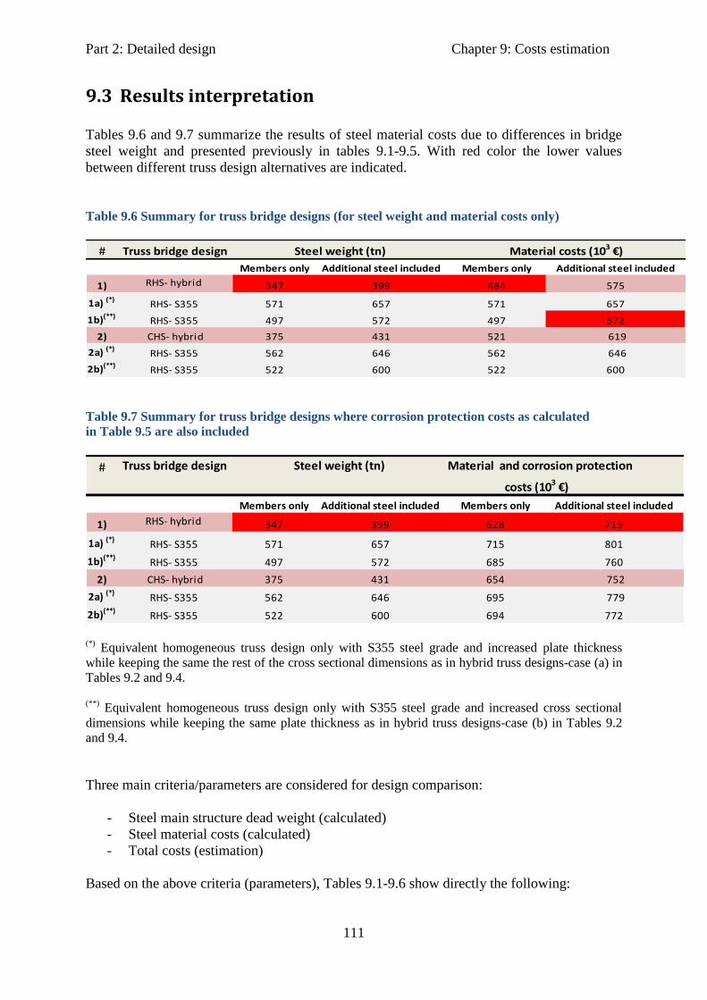
Part 2: Detailed design Chapter 9: Costs estimation
111
9.3 Results interpretation
Tables 9.6 and 9.7 summarize the results of steel material costs due to differences in bridge
steel weight and presented previously in tables 9.1-9.5. With red color the lower values
between different truss design alternatives are indicated.
Table 9.6 Summary for truss bridge designs (for steel weight and material costs only)
#
1)
1a) (*)
1b)(**)
2) 619
2a) (*)646
2b)(**)
Truss bridge design Steel weight (tn)
Members only Additional steel included
RHS- hybrid
CHS- hybrid
RHS- S355
RHS- S355
Members only
572
431
646
600
571
497
657RHS- S355
RHS- S355
571
522
Additional steel included
Material costs (103 €)
347 399 484 575
600
375
562
522
657
497 572
521
562
Table 9.7 Summary for truss bridge designs where corrosion protection costs as calculated
in Table 9.5 are also included
# Material and corrosion protection
1)
1a) (*)
1b)(**)
2) 752
2a) (*)779
2b)(**)
costs (103 €)
772
375
562
522
801
685 760
654
695
Additional steel included
347 399 628 719
CHS- hybrid
RHS- S355
RHS- S355
Members only
572
431
646
600
571
497
657RHS- S355
RHS- S355
715
694
Truss bridge design Steel weight (tn)
Members only Additional steel included
RHS- hybrid
(*)
Equivalent homogeneous truss design only with S355 steel grade and increased plate thickness
while keeping the same the rest of the cross sectional dimensions as in hybrid truss designs-case (a) in
Tables 9.2 and 9.4.
(**)
Equivalent homogeneous truss design only with S355 steel grade and increased cross sectional
dimensions while keeping the same plate thickness as in hybrid truss designs-case (b) in Tables 9.2
and 9.4.
Three main criteria/parameters are considered for design comparison:
- Steel main structure dead weight (calculated)
- Steel material costs (calculated)
- Total costs (estimation)
Based on the above criteria (parameters), Tables 9.1-9.6 show directly the following:

Part 2: Detailed design Chapter 9: Costs estimation
112
Hybrid design with RHS members and gusset plates has the lowest dead weight (≈8%
less than CHS hybrid and up to ≈65% less than S355 equivalent -case (a)).
Hybrid design with RHS members and gusset plates together with its equivalent “all
in S355” design (case b)) have the lower steel material costs in Table 9.6 (= 575000 €
and 572000 €, respectively, taking into account the 15% increment for welds and
additional steel plates for connections, ≈ 8% more than CHS hybrid design). Between
RHS hybrid and RHS homogeneous (case b) there is only a very small difference
(0.5%) in favor of homogeneous design due to lower price of S355.
Hybrid design with CHS members and cast joints together with its equivalent “all in
S355” design (case a)) have the lower required painted area (≈ 8% more than RHS
hybrid design in Table 9.5).
However, RHS hybrid design with gusset plates shows the lower “material &
corrosion protection” costs (≈ 5% less than CHS hybrid design in Table 9.7) showing
again the role that dead weight plays in calculating total costs.
9.3.1 Hybrid designs vs. “all in S355” designs
Moreover, Tables 9.1-9.7 show the following:
In Table 9.2 (case (a)) the plate thickness for the chord members needs to be increased by a
factor of 2, to more than 60 mm. The same holds for the thickness of the gusset plates (RHS
design) and casted joints (CHS design). This naturally leads to more steel material.
Higher thickness will also lead to significantly bigger weld volumes and maybe special
concerns with respect to welding procedure (e.g. higher preheating temperatures) and poorer
through thickness properties of the material may occur. In addition the plate thickness
exceeds 40 mm thus the min yield strength is not 355 MPa but 335 MPa. The steel dead
weight in this case (including additional steel), increases at about 65% for RHS design
(Tables 9.2 b ) and 9.6) and 39% for CHS design (Table 9.4 b)) in comparison to the hybrid
designs (Tables 9.1 and 9.3).
Material costs alone, based on steel dead weight including additional steel and welds (see
also table 9.6) are 14% more for the RHS S355 design and 4% more expensive for the CHS
S355 design in comparison to their equivalent RHS and CHS hybrid designs, respectively.
If also corrosion protection cost is added (table 9.7) the calculated costs are now 11% more
for the RHS S355 design and ≈ 4% more expensive for the CHS S355 design in comparison
to their equivalent RHS and CHS hybrid designs, respectively.
In table 9.2 (case (b)) the cross sectional dimensions need to be increased almost by a factor 2
to resist the loading. This will lead to longer welds, larger perimeter and thus, larger required
painted area, plus possibly more difficult handling (associated to labor costs). The bridge
dead weight (including additional steel) in this case increases to about 43% for RHS design
(Tables 9.2 (a) and 9.6) and 50% for CHS design (Tables 9.4 (a) and 9.6), in comparison to
the hybrid designs (Tables 9.1, 9.3 and 9.6). In addition the painting required area is
increased 31% and 29% respectively (Table 9.5).
In this case however, material costs alone, based on steel dead weight including additional
steel and welds (see also table 9.6) are 4% less for the RHS S355 design and 3% less

Part 2: Detailed design Chapter 9: Costs estimation
113
expensive for the CHS S355 design in comparison to their equivalent RHS and CHS hybrid
designs, respectively.
If also corrosion protection cost is added (table 9.7) the calculated costs are now 6% more for
the RHS S355 design and ≈ 4% more expensive for the CHS S355 design in comparison to
their equivalent RHS and CHS hybrid designs, respectively.
Therefore, in terms of total costs the hybrid designs seem to offer a more cost effective
solution than their equivalent “all in S355” truss bridge designs for the
‘Schellingwouderbrug’ (Tables 9.5-9.7), despite the higher price of high strength steel
material.
This is obviously due to significant difference in bridge steel dead weight (was calculated to
reach up to 65%!). Therefore, likewise to the corrosion protection and especially if smaller
cross sectional dimensions (width, height) are considered it can be expected that also other
important costs (e.g. in transportation, erection, welding volumes, maintenance requirements
etc.) will be in favor of hybrid designs.
However, this conclusion is based on the current steel prices and the fact that the same design
is used for both materials (equivalent design solutions -same design concept- has been
considered for trusses with S355 alone and with S690 in combination with S355).
9.3.2 Hybrid RHS design vs. hybrid CHS design
From the comparison between hybrid designs Tables 9.1, 9.3, and 9.5-9.7 seems that the
hybrid design with RHS members and gusset plates, provides lower dead weight (8%), lower
material costs (≈ 8% accounting only for additional steel for connections and welds and ≈ 5%
if also corrosion protection costs are included, Tables 9.5-9.7), smaller maximum member
thicknesses, but also slightly bigger painting required area (8%) in comparison to the hybrid
design with CHS members and cast joints.
However, RHS members are welded from plate elements, while CHS members can be found
available in stock. Furthermore, the cast joints can be optimized with respect to the required
thickness and particular shape in specific locations (e.g. bigger cast thickness close to the
center of the joint). These considerations will more likely outweigh the small differences
between the two designs in favor of the CHS hybrid design.
9.4 Future trends on price of high strength steel grade S690
The price of high strength steel material is currently quite high in comparison to normal S355
steel grade (70-75% more expensive). However, this fact is expected to change in the future
as the market demand for new steel grades will become higher.
A hypothetical case scenario for S690 price reduction per kg of material in the next 10-20
years is presented in Graph 9-1. The price of S355 and S460 is assumed constant to 1.00 €/kg
and 1.30 €/kg, respectively.

Part 2: Detailed design Chapter 9: Costs estimation
114
Graph 9-1 Future trend assumption for S690 steel price (€/ kg)
Based on this trend for S690 steel price in the next years, the bridge material costs (based on
steel dead weight including extra steel and welds) for designs presented in Tables 9.1-9.4 are
estimated and presented in Graph 9-2. Actually, a reduction of 20% in the next 20 years not
only is realistic but could also be considered conservative. As it is expected, material costs
(103 €) show a significant reduction due to lower high strength steel price.
The bridge steel material costs for “all in S355” designs are presented as straight lines since
the price of S355 is assumed to remain constant over the years. This serves in understanding
better the cost benefits that can be gained with HSS steel grades due to weight reduction.
Similar trend can be expected for the total costs of the hybrid bridge designs, when the plate
thicknesses are kept relatively low (up to 30 mm).
Graph 9-2 Material costs estimation for hybrid and all in S355 truss bridge designs assuming
price reduction for S690 in comparison to S355 steel grade.
Also, in Graph 9-3 the cost reduction for the hybrid designs in comparison to “all in S355”
designs (case (b)) expressed in percentage (%) is presented also as a function of the S690
future steel price reduction. It is obvious that the benefits to be gained (due to weight savings)
from high strength steel material become larger as the price of the material drops.
1.75 1.6 1.5 1.4 1.3 1.2 1.15
0
0.5
1
1.5
2
2012 2015 2018 2021 2024 2027 2030
S69
0 (
€/k
g)
Year
S690 steel price
S690 steel price
575
540 517
493 470
447 436
619
582 557
532 508
483 470
300
350
400
450
500
550
600
650
1.75 1.6 1.5 1.4 1.3 1.2 1.15 Mat
eria
l co
sts
(10
3 €
) b
ase
d o
n
bri
dge
dea
d w
eigh
t (t
n)
Price future trend of HSS grade S690 (€/kg)
Bridge steel material costs (103 € )
RHS hybrid design
CHS hybrid design
RHS and S355
CHS and S355

Part 2: Detailed design Chapter 9: Costs estimation
115
Graph 9-3 Cost reductions (%) for hybrid designs in comparison to their equivalent “all in
S355” designs (case (b): with increased cross sectional dimensions keeping the same plate
thickness)
Note: In Graph 9-3, the S690 steel price starts from 1.60 €/kg and not from 1.75 €/kg (current
price) as in the two previous graphs (Graph 9-1 and 9-2) because in this case the cost
reduction is in favor of “all in S355”designs (i.e. cost reduction is 4% for RHS and 3% for
CHS “all in S355” case (b) designs in comparison to their equivalent hybrid designs). Thus it
was preferred not to include a negative value in the graph (sign ‘-’ reflects the hybrid bridge
material costs increment in this case).
It must be noted that the estimated future prices for S690 presented in Graph 9-1 cannot be
considered accurate as they only serve for comparison of how the material price influences
the results calculated taken as reference the ‘Schellingwouderbrug’.
However, in the next years more and more experience will be gained with HSS and the cost
benefits that can be gained from less steel weight (i.e. less steel material) which will also lead
to higher market demands for these higher steel grades. Furthermore, more fabricators will
become familiar and work with the new material and thus the price will drop.
Based on these factors, a reduction of about 15% in price of S690 steel grade in the next 20
years can not only be a realistic but even a conservative expectation.
6.0
10.7
15.9
21.6
27.9
31.3
3.3
7.9
12.9
18.4
24.5
27.8
0
10
20
30
40
1.6 1.5 1.4 1.3 1.2 1.15 Co
sts
red
uct
ion
(%
) fo
r h
ybri
d d
esig
ns
Price future trend of HSS grade S690 (€/kg)
"All in S355" vs. Hybrid designs-Material costs reduction
RHS hybrid design
CHS hybrid design

Chapter 10: Conclusions
116
10 Conclusions
The critical question to be answered is: Can high strength steel help reducing total costs in
bridge construction?
In this thesis a literature survey together with a case study have been presented. The case
study consists of preliminary hybrid -using high strength steel grade S690 (min fy = 690
MPa) in combination with S460 (min fy = 460 MPa) and S355 (min fy = 355 MPa) steel
grades- but also homogeneous bridge designs (the whole design in S355 steel grade) for a
long span bridge (L > 100m).
From this MSc study the following can be concluded:
1. In Chapter 3 it has been shown that bridges using high strength steel grades (HSS up
to S690 and usually in combination with lower steel grades-hybrid designs) can offer
competitive and cost effective solutions for almost all bridge types (i.e. truss bridge,
girder bridge, box girder bridge, cable stayed bridge and suspension bridge) and span
length ranges (i.e. small, medium, and large), resulting mainly in significant weight
savings.
2. The choice for a certain bridge type at a given location with its specific boundary
conditions influences whether HSS will be favorable or not.
3. Application of high strength steel grades (mainly as quenched and tempered Q&T
quality) in (hybrid) bridge design results in large weight savings (e.g. S690 steel grade
in hybrid (warren) truss design can result in over 50% steel weight reduction in
comparison to an equivalent homogeneous design with mild steel) especially in cases
where strength governs.
4. In bridge types and in members where the governing criterion is strength, such as in
truss bridges (i.e. members under tension or even compression if buckling behavior is
not decisive) the use of HSS, with associated cost benefits, will be favored. Certain
design improvements/changes especially for the connections (e.g. choosing for cast
joints in truss bridges instead of direct member to member welded connections for
better fatigue behavior), if necessary, should be considered in an early design stage.
5. Fatigue is commonly the governing criterion in steel (highway and railway) bridges
especially for members under bending as in the main girders in arch bridges and in
connections. This bridge type will likely not be favorable for HSS.
6. Increased bridge dead weight (for example larger bridge spans) for a given traffic load
(i.e. designing for a given traffic category within a certain fatigue life) is in favor of
higher steel grades as the static stresses will be higher while fatigue stress amplitude
will be smaller due to the increased mass.
7. To improve fatigue behavior and allow economical use of HSS a concrete deck (in
composite action or not) can be preferred over an orthotropic steel deck. The concrete
deck adds to the bridge mass (and thus static stresses in the steel members are
increased) and it is has less fatigue sensitive details than orthotropic steel deck. If also

Chapter 10: Conclusions
117
in composite action, the steel members can be further reduced, thus less steel material,
less steel weight and finally even less total costs (costs savings in fabrication,
handling, lifting, transportation, corrosion protection, foundations etc.).
8. Considering equivalent homogeneous and hybrid bridge designs (and if the same deck
type is considered, e.g. concrete) it is estimated that lower steel self-weight that can
be achieved with HSS, will have an influence on foundations (e.g. smaller piers may
be required especially for large spans), transportation, lifting and erection costs, while
smaller cross sectional areas will have a positive effect on maintenance (e.g. smaller
painted area required for corrosion protection) and fabrication (especially welding)
costs, especially in small thicknesses.
9. Based on preliminary designs of a long span bridge, it has been shown that high
strength steel grade S690 can provide cost effective and thus competitive bridge
solutions, especially when it is used in combination with lower steel grades (in hybrid
design) and in structures/members where the load is mainly transferred as axial forces
like in truss bridges where strength is usually the governing criterion. In members
under bending fatigue stresses at certain locations (e.g. truss joints) may be
significant.
10. Nevertheless, in cases where fatigue stresses are locally quite high (e.g. fatigue
sensitive details in critical joints) alternative design concepts (e.g. different joint
configuration and/or locally higher plate thicknesses, moving welds away from
locations of high stresses, etc.) or even post weld treatment can improve the fatigue
sensitive details.
Additional conclusions based on a literature survey have been presented in Chapter 4.
Case study: ‘Schellingwouderbrug’
Moreover, based specifically on the case study for the Schellingwouderbrug the following
can be concluded and used as feedback for future bridge (hybrid) designs with S690 steel
grade.
For members verification
The design rules (according to EN 1993-1-1 and EN 1993-1-12) and methods of
global elastic analysis for normal steel grades can be generally used for design of high
strength steel (HSS) members up to S700 steel grade too.
Hybrid designs with high strength steel allows for significant bridge steel weight
reduction –up to 65% for RHS design and 50% for CHS design- in comparison to
their equivalent homogeneous truss designs due to smaller plate thicknesses and/or
overall cross sectional dimensions.
The above statement implies that in order to be favored from the benefits of less steel
material, the overall design philosophy (e.g. choice of bridge type, L/D ratios,
detailing of connections with respect to fatigue), can be altered or adjusted to the steel
material properties and vice versa. In that respect hybrid designs (combination of steel

Chapter 10: Conclusions
118
grades for different bridge regions and/or for steel members) give more weight
savings and (material and total) cost benefits than homogeneous designs.
Stability –in and out- of plane does influence the design if relatively slender and/or
long members (large buckling lengths) are used. In this case static stresses are limited
by the buckling strength (fb, rd) which governs the design. This is mainly because:
the value of flexural buckling reduction factor χ reduces as the steel grade increases
(considering the same buckling curve), resulting in bigger differences between static
and buckling strength values. However, the resulting buckling strength is still higher
for members with high strength steel in comparison to members with mild steel
grades;
the higher the steel grade the lower the slenderness (c/t) limits (Table 5.2 EN 1993-1-
1) for cross sectional classification. In result, the same cross section can be classified
as class 2 for S355 and class 3 (or even class 4) for S690. This becomes more
pronounced in members under pure compression where the limits are already stricter
than for members in bending;
Nevertheless, the same cross section with S690 classified for example as class 3 will
result in higher member resistance against buckling (i.e. higher buckling strength)
than a class 2 section made out of mild steel grades.
Thus, high strength steel grades can still provide cost benefits for members under
compression.
Moreover, the plate thickness should be kept as low as possible to avoid extra
fabrication costs (e.g. for plate thicknesses over 30 mm expensive preheating and high
welding volumes will increase fabrication costs).
If stability is the governing criterion, smaller member length (smaller field length,
lower bridge height, bigger inclination for diagonal brace members for truss bridges,
etc.) may be proved favorable in terms of total costs despite the more joints and the
higher number of brace members that will add to fabrication costs.
Fatigue stresses caused by bending actions are found to be 2-3 times higher than
fatigue stresses due to axial forces, independent of the steel grade.
Fatigue stresses were taken into account for the choice for the members cross section
and for using HSS, and for most trial designs fatigue was not the decisive criterion.
Thus, benefits due to weight savings and reduced dimensions could be gained.
For the arch bridge design though, fatigue stresses limit the static stresses also at such
levels where it was considered inefficient to use HSS grades. Thus, specifically for
the ‘Schellingwouderbrug’ an arch bridge (with the given configuration) cannot
provide any benefit in comparison to mild steel grade S355.

Chapter 10: Conclusions
119
For connections verification
In this study, design of connections has only been investigated for (welded) rectangular
hollow section (RHS) steel members in a Warren type truss bridge configuration for the
‘Schellingwouderbrug’.
Ensuring that the design of truss joints is within certain limits covered in section 7 in
EN 1993-1-8, design resistances for lattice girder connections with RHS members can
be calculated using tables and formulas provided in Eurocode 3 part 1-8 “Design of
Joints”. These, apply to sections at least class 2. However, a class 3 section in HSS
could give more weight savings and thus costs benefits. In this case local plate
buckling should be also checked.
For strength verifications using tables in EN 1993-1-8, a reduction factor 0.9 and 0.8
should be applied to all (conservatively) the calculated design resistances for S460
and for higher (e.g. S690) steel grades, respectively, to account for larger
deformations in the face of the RHS chord member.
For fatigue verifications tables in EN 1993-1-9 for lattice girder joints and related S-N
curves for nominal stress ranges, apply only to a quite small range of cross sectional
dimensions, independently of the steel grade.
FEM modeling of the connection is advised to be used for determination of actual hot
spot (geometrical) stress ranges and actual stress concentration factors (SCFs).
SCFs parametric formulas are also available (e.g. in CIDECT Design Guide No.8) but
only for certain types of connections and for a range of cross sectional dimensions.
Typical lattice girder joints with RHS members for the ‘Schellingwouderbrug’ were
found to be unsuitable because of fatigue. High stress ranges together with high SCFs
(from parametric formulas) resulted in unacceptable fatigue damage (D>> 1). Finite
element modeling with plate elements is however necessary for calculating the hot
spot stress ranges and the actual fatigue damage.
For fatigue verifications a more favorable traffic category (i.e. Nobs/year/slow lane =
0.5*106 from Table 4.5 EN 1991-2:2003), than for most highway bridge designs, has
been considered based on the specific bridge location and the flow rates of lorries
expected to cross it. Thus, fatigue damage can be expected to be even higher in case
Nobs/year/slow lane = 2*106 are to be considered for a given bridge design. If the
choice for higher traffic category is done in combination with larger span length, thus
higher bridge mass the fatigue effect will be less severe (i.e. reduced fatigue stress
amplitude).
Fatigue sensitive details can be improved by altering the design of the connections. In
section 8.6 the alternative design using relatively thick gusset plates for members
webs at joints location resulted in significant improvement with respect to fatigue.
Damage calculation is satisfied almost for all critical joints. Here again detailed
modeling of the connection with plate elements is necessary for actual fatigue
assessment.

Chapter 10: Conclusions
120
For the design with circular hollow section (CHS) members cast joints are assumed
for the connections. This is already a favorable design for fatigue based on literature
findings. Once again, detailed modeling of the connection with plate elements is
necessary to determine the actual shape of the casting and for accurate fatigue
assessment.
For costs
Hybrid designs show significant weight reduction (even 65% for truss with RHS
members) in comparison to their equivalents “all in S355” designs.
Calculating material costs for two hybrid truss designs and assuming that S690 is 75%
more expensive than S355 it has been shown that hybrid construction shows only
slightly higher material costs (4% higher with RHS members and 3% more with CHS
members) in comparison to homogeneous (S355) designs.
It was eventually not possible to calculate the total costs in detail (including
fabrication, erection, transportation and maintenance). However, it is expected to be
in favor of hybrid bridge designs. This is based on the estimation that, lower dead
weight will have an influence on foundations (e.g. smaller piers may be required),
transportation and erection costs, while smaller cross sectional areas will have a
positive effect on maintenance (smaller painted area required especially for hybrid
design with CHS members) and fabrication (especially welding) costs, especially in
small thicknesses (thicknesses are kept relatively low- max t =30 mm for RHS hybrid
design and 32 mm for CHS hybrid design- thus no preheating and no special
machining equipment is necessary).
Estimating finally that the price for HSS grade S690 will be reduced within the next
decades it has been shown that the cost benefits to be gained from weight savings
increase significantly as the high strength steel price reduces.
For example, a 15% price reduction for S690 steel grade results up to 10% lower steel
material costs for the ‘Schellingwouderbrug’ (see also Charts 9.1- 9.3).
Chapter 11: Recommendations for further research
121
11 Recommendations for further research
The following subjects are suggested for further investigation, as it was unfortunately not
possible to cover them in this thesis project.
Homogeneous (made completely out of a single steel grade) hollow section members
have only been examined as the cross sections of bridge members. However, bridge
solutions with other homogeneous but also hybrid (e.g. HSS in the flanges and lower
grades for the webs) cross sectional types (e.g. built up sections, I girders, etc.) can be
examined also and compared with the current designs in order to investigate the
efficiency of HSS hollow section members.
For the truss design of the ‘Schellingwouderbrug’ the larger available economical L/D
ratio (= 15) with respect to S355 steel grades is considered for the hybrid designs as
well. However most economical L/D ratios for HSS can be even bigger than normal
steel grades. Therefore, further investigation is suggested together with truss
optimization with respect to L/D ratio which may increase even more the cost benefits
to be gained from higher steel grades.
Design of connections is one of the most critical aspects especially when high
strength steel is used as it directly influences the design of members and fabrication
costs. More data from large scale test specimens for connections and even with more
slender (higher class 3 or even 4) steel members are necessary in order to develop
new simplified formulas for these steels.
In addition, the estimated 0.8 reduction factor specifically for the design resistance in
case of hollow section members made in high strength steel (> S460) needs to be
verified by additional testing.
Detailed fatigue design and determination of stress concentration factors (SCFs) for
lattice girder connections with RHS members and gusset plates (section 8.6
alternative 2 for connections) using FEM analysis program and modeling the
connection in detail is highly recommended.
When hand (analytical) calculations are performed for fatigue verifications (as in the
detailed design phase for the ‘Schellingwouderbrug’ with RHS members and max
plate thickness 30 mm) it is possible that a relevant S-N curve for the calculated hot
spot stress ranges does not exist for RHS members with plate thicknesses above 16
mm. Hot spot S-N curves therefore need to be developed and additional testing data
(preferably from large scale tests) are needed for this scope.
In order to make bridge design with HSS and hollow section members more economic
(for example by using more slender sections), strength verification of connections
may most of the times be out of the range of the simplified (generalized) formulas
Chapter 11: Recommendations for further research
122
provided in EN 1993-1-8, as they cover only a limited range of geometrical
parameters and are applicable for class 1 or 2 sections only. Thus, additional data are
necessary to extend the formulas provided in EN 1993-1-8.
References
123
References - Part 1B & Part 2
[1] KARGO project, Iv-Infra: Project
number INPA080437-R
[2] Dr. M.H. Kolstein, Prof. Ir. F.S.K.
Bijlaard. “Steel bridges” (2011), Faculty of
Civil Engineering and Geosciences,
Department Design and Construction-
Section Structural and Building
Engineering.
[3] Dr. A. Romeijn. “Steel-Concrete
Bridges-III” (2006), Faculty of Civil
Engineering and Geosciences, Department
Design and Construction-Section
Structural and Building Engineering.
[4] Dr. A. Romeijn. “Steel Bridges-I”
(2006), Faculty of Civil Engineering and
Geosciences, Department Design and
Construction-Section Structural and
Building Engineering.
[5] Suraj Parkash et al. “Prestressed
concrete beams under fatigue loading”.
Advances in Bridge Engineering March
24-25, 2006, New Delhi.
[6] J. Wardenier et al. “Design guide 1 for
circular hollow section (CHS) joints under
predominately static loading”. CIDECT:
Design with CHS-Second edition (2008).
[7] J. Wardenier. “Hollow sections in
structural applications”, (2002).
[8] ESDEP WG 15B- Structural systems:
Bridges, Lecture 15B.6: “Box Girder
Bridges”.
[9] ESDEP WG 15B- Structural systems:
Bridges, Lecture 15B.5: “Truss Bridges”.
[10] R.J.M. Pijpers¹ ², M.H. Kolstein².
“Fatigue strength of truss girders made of
Very High Strength Steel”, (2010).
¹Materials Innovation Institute, ²Delft,
Netherlands, Delft university of
Technology, Delft, Netherlands.
[11] ESDEP WG 15B- Structural systems:
Bridges, Lecture 15B.7: “Arch Bridges”.
[12] Fidelis Rutendo Mashiria,
, Xiao-Ling
Zhaob. “Square hollow section (SHS) T-
joints with concrete-filled chords subjected
to in-plane fatigue loading in the brace”. a
School of Engineering, University of
Western Sydney, Penrith South DC, NSW
1797, Australia ,b Department of Civil
Engineering, Monash University, Clayton,
VIC. 3800, Australia
[13] J. Wardenier et al. CIDECT design
guide 1- For circular hollow section (CHS)
joints under predominately static loading.
Second edition, April 2010.
[14] J. Wardenier, et al. CIDECT design
guide 3- For rectangular hollow section
(RHS) joints under predominately static
loading. Second edition, April 2010.
[15] D. Dütta, J. Wardenier, et al. CIDECT
design guide 7- For fabrication, assembly
and erection of hollow section structures,
1998.
[16] X.-L. Zhao et al. CIDECT design
guide 8- For circular and rectangular
hollow section welded joints under fatigue
loading, 2001

Appendix A: Trial preliminary designs for the ‘Schellingwouderbrug’ Loads
general
124
Appendix A: Preliminary designs
A.1 Loads and load combinations
Combinations of actions (NOT for fatigue)
For ULS verifications: characteristic load combination according to EN 1990 is used.
For deflections (SLS): frequent load combination according to EN 1990 is used.
Load groups and traffic load models
For all the three preliminary designs two main load groups are considered for the vertical
loads:
Dead loads (self-weight+ asphalt layer) (EN 1991-1-1 for permanent actions).
Traffic loads: LM1 (UDL+TS) and gr1a (EN 1991-2 for variable actions due to traffic).
For strength verifications (ULS)
Group load model (gr1a) consists of load model 1 (LM1) as the governing variable action
which acts in combination with the vertical load qfk on the cycle/foot path.
For the cycle/foot path a uniformly distributed load is applied (EN 1991-2:2003):
qfk= 2+ 120/ (L+30) =2.9 kN/m2
According again to EN 1991-2:2003 (see also Figures 1, 2 and 3), the roadway of the
‘Schellingwouderbrug’ (clear roadway width= 7 m) is divided into 2 notional lanes of 3 m
each and a remaining part of 1 m.
Load model 1 (LM1) should be applied in each notional lane and on the remaining areas. It
consists of a uniformly distributed load (UDL system) and double-axle concentrated loads
(TS system) representing heavy lorries. For the assessment of general effects the TS should
be assumed to travel centrally along the axes of notional lanes.

Appendix A: Trial preliminary designs for the ‘Schellingwouderbrug’ Loads
general
125
Figure A - 1 Division of the roadway into notional lanes, (EN 1991-2:2003)
Figure A - 2 LM1-values (top) and application (bottom- left for global verifications (UDL+TS),
right for local verifications (TS)), (EN 1991-2:2003).
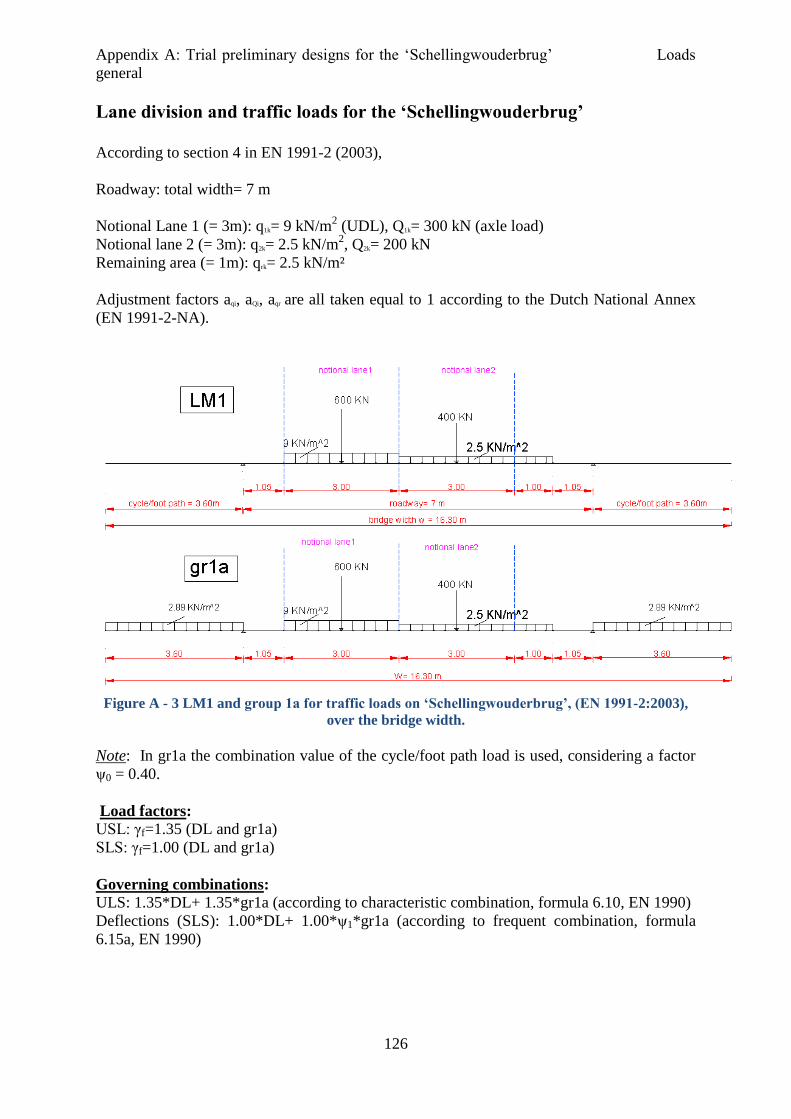
Appendix A: Trial preliminary designs for the ‘Schellingwouderbrug’ Loads
general
126
Lane division and traffic loads for the ‘Schellingwouderbrug’
According to section 4 in EN 1991-2 (2003),
Roadway: total width= 7 m
Notional Lane 1 (= 3m): q1k= 9 kN/m2 (UDL), Q1k= 300 kN (axle load)
Notional lane 2 (= 3m): q2k= 2.5 kN/m2, Q2k= 200 kN
Remaining area (= 1m): qrk= 2.5 kN/m²
Adjustment factors aqi, aQi, aqr are all taken equal to 1 according to the Dutch National Annex
(EN 1991-2-NA).
Figure A - 3 LM1 and group 1a for traffic loads on ‘Schellingwouderbrug’, (EN 1991-2:2003),
over the bridge width.
Note: In gr1a the combination value of the cycle/foot path load is used, considering a factor
ψ0 = 0.40.
Load factors:
USL: γf=1.35 (DL and gr1a)
SLS: γf=1.00 (DL and gr1a)
Governing combinations:
ULS: 1.35*DL+ 1.35*gr1a (according to characteristic combination, formula 6.10, EN 1990)
Deflections (SLS): 1.00*DL+ 1.00*ψ1*gr1a (according to frequent combination, formula
6.15a, EN 1990)

Appendix A: Trial preliminary designs for the ‘Schellingwouderbrug’ Loads
general
127
For Fatigue (ULS)
In the preliminary phase, fatigue is treated as a simple global check based on maximum stress
range (Δσ) caused by a single heavy vehicle on the bridge. This has been done only for the
truss and the arch bridge in Scia Engineer FEM program.
The maximum stress range (Δσ) at the most critical (fatigue) location for each member is
calculated by applying FLM3 (single vehicle model) according to EN 1991-2 (2003) (Figure
4). The vehicle is positioned centrally on the notional lane closer to the truss plane to cause
the most severe effect on the truss members.
Longitudinally, it is positioned in 3 different locations (i.e. midspan, close to supports,
random intermediate position) and the most severe load position for each member, causing
the maximum (fatigue) stress level on the member is considered.
Figure A - 4 Fatigue load model 3
This stress level is limited by the calculated fatigue strength. This has been obtained by
choosing the most relevant fatigue detail in EN 1993-1-9 and the corresponding fatigue class
for our design.
The fatigue class, thus chosen is class 71 (Δσc= 71 MPa at 2*106 cycles). Using slope m=3
and formulas in EN 1993-1-9, the fatigue limit (ΔσD in Figure 5) is then calculated which
corresponds to an allowable stress level of ΔσD=52 MPa. More specifically, ΔσD is calculated
using the formula in EN-1993-1-9:
ΔσDm
*5*106
= Δσcm
*2*106, m=3
Where,
ΔσD : constant amplitude fatigue limit at 5*106 cycles
Δσc :maximum strength at 2*106
cycles depending on detail class (Detail class 71, Δσc=71
MPa)
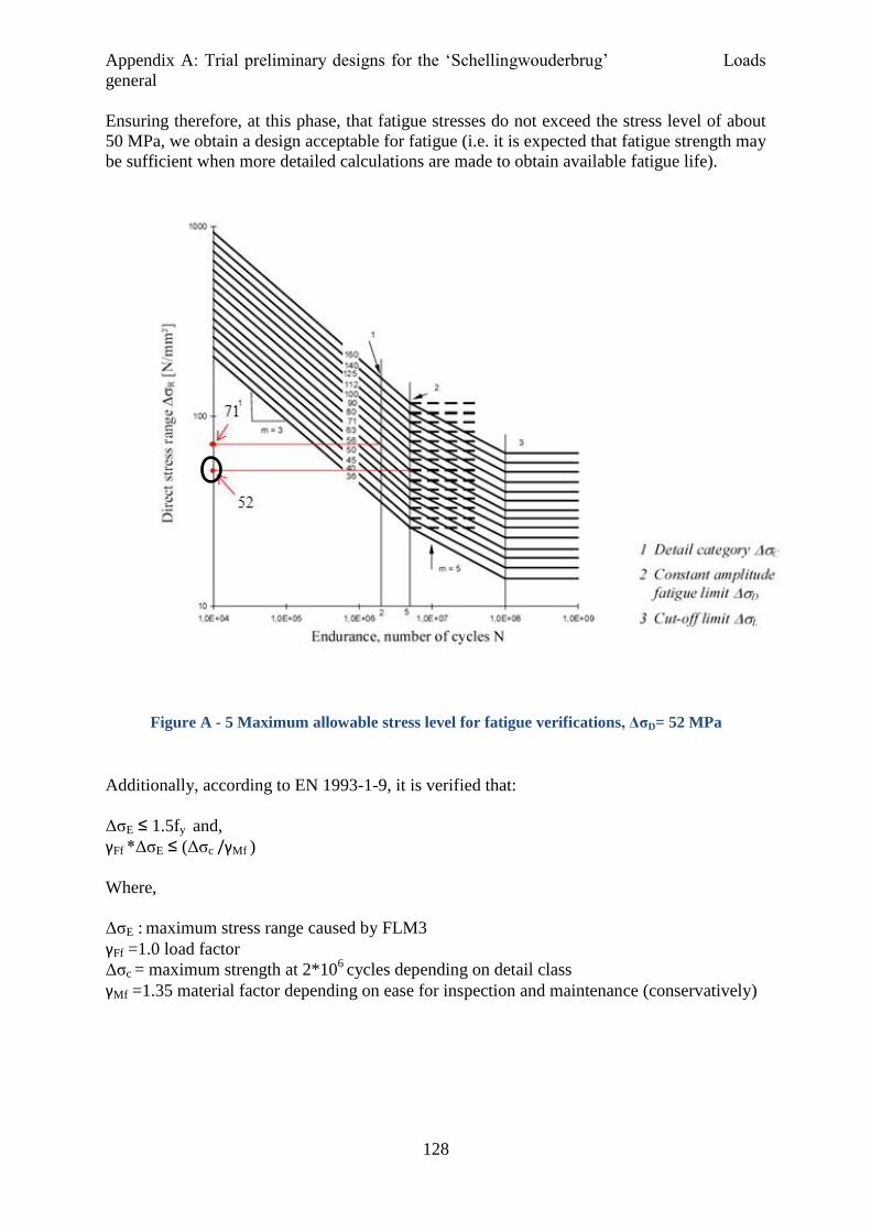
Appendix A: Trial preliminary designs for the ‘Schellingwouderbrug’ Loads
general
128
Ensuring therefore, at this phase, that fatigue stresses do not exceed the stress level of about
50 MPa, we obtain a design acceptable for fatigue (i.e. it is expected that fatigue strength may
be sufficient when more detailed calculations are made to obtain available fatigue life).
Figure A - 5 Maximum allowable stress level for fatigue verifications, ΔσD= 52 MPa
Additionally, according to EN 1993-1-9, it is verified that:
ΔσE ≤ 1.5fy and,
γFf *ΔσE ≤ (Δσc /γMf )
Where,
ΔσE : maximum stress range caused by FLM3
γFf =1.0 load factor
Δσc = maximum strength at 2*106
cycles depending on detail class
γMf =1.35 material factor depending on ease for inspection and maintenance (conservatively)

Appendix A: Trial preliminary designs for the ‘Schellingwouderbrug’ Box girder bridge
129
A.2 Trial preliminary bridge designs
a. Trial box designs
Since the box girder section is designed to be extremely slender (L/D = 64) the governing
criteria initially to be checked are strength and stiffness. In addition, plate buckling and shear
lag effects should also be taken into account by using an effective cross section for the box
girder. Initially, however, the whole box section is assumed effective for simplicity.
Several trial box configurations have been attempted, choosing different width dimensions
(with respect to vertical or inclined webs) and plate thicknesses (see also AutoCAD file “Box
girder trial designs”).
This is done, to investigate what are the minimum possible dimensions to give sufficient
moment capacity and acceptable midspan deflections.
For the deck an orthotropic steel plate is chosen acting as the top flange of the box in all
cases. A concrete deck would add extra weight which would cause even bigger deflections in
an already extremely slender box section. Here, only two of the trial box designs are
presented in more detail.
a1) Steel Box 1 with orthotropic steel plate
Figure A - 6 Cross section of the Box 1 girder (top) and of the longitudinal stiffeners (bottom) at
the top flange of the box girder, c.t.c distance = 600 mm.
Appendix A: Trial preliminary designs for the ‘Schellingwouderbrug’ Box girder bridge
130
Cross sectional dimensions
Top flange: tf,top= 30 mm (steel plate thickness is 20 mm) and steel grade assumed to be used
for the top flange is S355.
Web: tw= 20 mm (S460)
Bottom flange: tf,bot= 30 mm (S690)
The trapezoidal stiffeners for the deck plate (Figure 6) are taken into account as an equivalent
thickness equal to teq, ls = Asl/w and included in the thickness of the top flange (ttop).
Plate thicknesses are chosen, keeping material and fabrication costs in mind. Therefore,
especially for the bottom flange (S690 grade) a limitation that the plate thickness should be
kept rather small (t ≤ 40-50 mm), is set already from the beginning.
Box Description
Top flange: The top plate is an orthotropic steel deck with plate thickness 20 mm. The
longitudinal stiffeners are distributed over the width of 16.3 m and added as an equivalent
thickness on the top flange, to simplify the calculations procedure.
Hence,
ttop= tplate+ teq, ls
teq, ls= Als, tot/w : equivalent thickness for Longitudinal stiffeners on the top flange
Where,
Als, tot: is the total area of the longitudinal stiffeners over the width w.
w: is the width of the top flange
This flange is in compression and since the center of gravity is closer to the top (more
material and bigger area at the top flange to take the resulting force), it carries smaller
stresses (<355 N/mm2) than the bottom flange and therefore, S355 steel grade is chosen.
Bottom flange: The bottom flange is under tension. The stresses are quite high (>500 N/mm2)
and therefore steel grade S690 can efficiently take over these stresses.
Web: Vertical webs are considered with c.t.c distance of 9.10 m. The thickness is kept
constant and equal to 20 mm. The stresses in the web due to global bending exceed 500
N/mm2 close to the bottom flange. This means that even a steel grade of S460 is suitable
assuming local yielding for the web.
Loads
Two types of vertical loads are considered for calculating the internal forces in the steel main
structure (not for fatigue):
Dead load
- Steel box

Appendix A: Trial preliminary designs for the ‘Schellingwouderbrug’ Box girder bridge
131
Density for Steel: γ= 78.5 kN/m³, [EN 1991-1-1]
Self-weight= Area*density= 65.8 kN/m
- Pavement
Mastic asphalt is assumed over the whole bridge width with thickness t= 8 mm and density
γ= 20 kN/m³ (EN 1991-1-1 suggests values between 18-22 kN/m³).
Mastic asphalt dead weight: Aasph. * γasph = 2.6 kN/m
Traffic loads
gr1a: q,k1a= UDL,k (LM1)+ 2*0.40*qfk= 37+ 2*0,40*2.89*3.60= 40 kN/m over the bridge
length
Qk,1a= TS,k (LM1)= 1000 kN assumed to act in the centerline of the bridge
Maximum moment (DL+ gr1a, γf=1 .35):
My,sd= 247522 kNm
Simplification for global analysis
The position of the TS depends on the internal force to be calculated. So, in a simple
supported bridge span, for obtaining the maximum global moment My, the most unfavorable
position of the TS is at the midspan (cross section A-A). For the maximum shear force Vz, the
TS is positioned very close to the supports (cross section B-B).
Figure A - 7 Critical positions for the TS, over the bridge span for global analysis, at the
preliminary stage.
Maximum moments: My,sd = 1.35* (DL+qk,1a L2) / 8 + 1.35* {Qk,1a*L/4}
Maximum shear: Vz,sd = 1.35* {DL+qk,1a}*L/2 + 1.35* Qk,1a
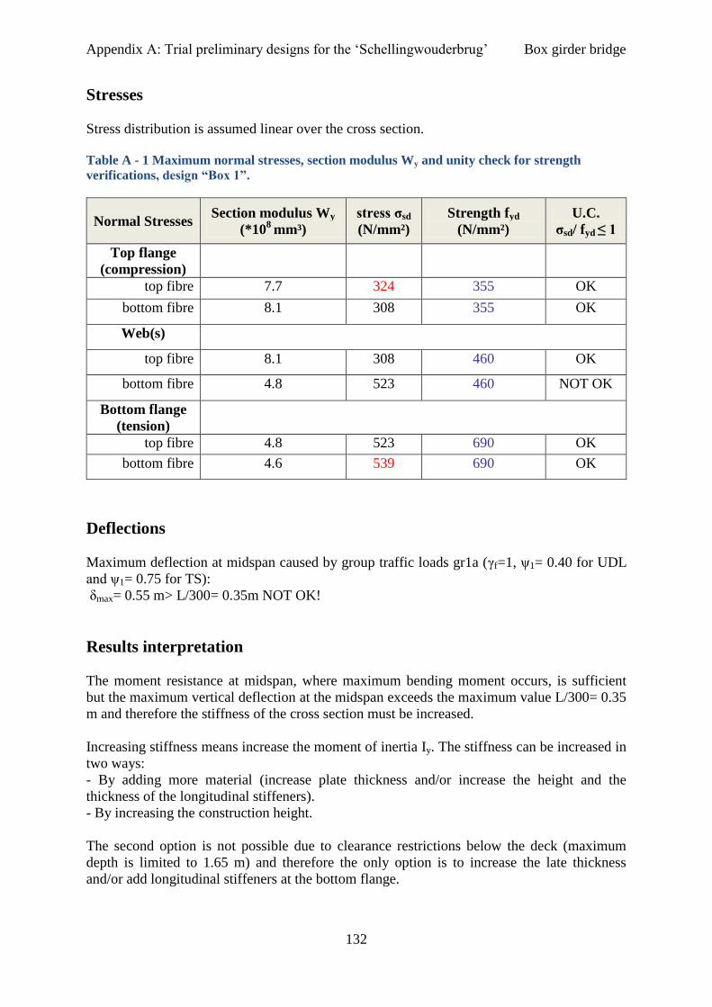
Appendix A: Trial preliminary designs for the ‘Schellingwouderbrug’ Box girder bridge
132
Stresses
Stress distribution is assumed linear over the cross section.
Table A - 1 Maximum normal stresses, section modulus Wy and unity check for strength
verifications, design “Box 1”.
Normal Stresses Section modulus Wy
(*108
mm³)
stress σsd
(N/mm²)
Strength fyd
(N/mm²)
U.C.
σsd/ fyd ≤ 1
Top flange
(compression)
top fibre 7.7 324 355 OK
bottom fibre 8.1 308 355 OK
Web(s)
top fibre 8.1 308 460 OK
bottom fibre 4.8 523 460 NOT OK
Bottom flange
(tension)
top fibre 4.8 523 690 OK
bottom fibre 4.6 539 690 OK
Deflections
Maximum deflection at midspan caused by group traffic loads gr1a (γf=1, ψ1= 0.40 for UDL
and ψ1= 0.75 for TS):
δmax= 0.55 m> L/300= 0.35m NOT OK!
Results interpretation
The moment resistance at midspan, where maximum bending moment occurs, is sufficient
but the maximum vertical deflection at the midspan exceeds the maximum value L/300= 0.35
m and therefore the stiffness of the cross section must be increased.
Increasing stiffness means increase the moment of inertia Iy. The stiffness can be increased in
two ways:
- By adding more material (increase plate thickness and/or increase the height and the
thickness of the longitudinal stiffeners).
- By increasing the construction height.
The second option is not possible due to clearance restrictions below the deck (maximum
depth is limited to 1.65 m) and therefore the only option is to increase the late thickness
and/or add longitudinal stiffeners at the bottom flange.

Appendix A: Trial preliminary designs for the ‘Schellingwouderbrug’ Box girder bridge
133
a2) Steel Box 2 with orthotropic steel plate
Figure A - 8 Cross section of the Box 1 girder (top) and of the longitudinal stiffeners (bottom) at
the top flange of the box girder, c.t.c distance = 600 mm.
Cross sectional dimensions
Top flange: tf,top= 50 mm (plate thickness is 37 mm) (S355)
Web: tw= 20 mm (S355 or S460)
Bottom flange: tf,bot= 50 mm (without stiffeners or tplate = 37 with stiffeners) (S460)
Longitudinal stiffeners considered as equivalent thickness teq,ls.= Als/w and included in the top
flange thickness tf,top.
Loads
Dead load
- Steel box:
Density for Steel: γ= 78.5 kN/m³, (EN 1991-1-1)
Self-weight= Area*density=104.6 kN/m
-Pavement:
Mastic asphalt is assumed over the whole bridge width with thickness t= 8 mm and density=
20 kN/m³ (EN 1991-1-1 suggests values between 18-22 kN/m³).
Mastic asphalt self-weight: Aasph * 20 = 2.6 kN/m
DL,tot = Box self-weight + Mastic asphalt
Traffic loads
gr1a: UDL,k= UDL,k (LM1)+ 2*0.40*qfk= 37+ 2*0,40*2.89*3.60= 40 kN/m over the bridge
length
TS,k= TS,k (LM1)= 1000 kN assumed to act in the centerline of the bridge

Appendix A: Trial preliminary designs for the ‘Schellingwouderbrug’ Box girder bridge
134
Maximum moment (DL+ gr1a, γf=1 .35) My,sd= 319674 kNm
Stresses
Stress distribution is assumed linear over the cross section.
Table A - 2 Maximum normal stresses, section modulus Wy and U.C. for strength verifications,
design “Box 2”.
Normal Stresses Section modulus Wy
(*108
mm³)
stress σsd
(N/mm²)
Strength fyd
(N/mm²)
U.C.
σsd/ fyd ≤ 1
Top flange
(compression)
top fibre 1.2 266 355 OK
bottom fibre 13 245 355 OK
Web(s)
top fibre 13 245 460 OK
bottom fibre 7.8 412 460 OK
Bottom flange
(tension)
top fibre 7.8 412 500 OK
bottom fibre 7.4 433 500 OK
Deflections
Maximum deflection at midspan (gr1a, γf=1, ψ1= 0.40 for UDL and ψ1= 0.75 for TS):
δmax=0.349 m< L/300= 0.35 m OK!
Results interpretation
The moment resistance at midspan where the maximum bending moment is found, is
sufficient and the maximum vertical deflection at the midspan is also below the maximum
value L/300= 0.35 m. These plate thicknesses are already quite large especially when it
comes to fabrication costs of high strength steels. In these thicknesses preheating is necessary
and so extra costs will be added.
It is important however to note that the maximum vertical deflection is calculated, based only
on variable load from traffic. For the dead loads it is likely that the limit will again be
exceeded. Usually, in long span bridges, dead load causes much bigger deflections than
traffic loading. However that does not influence the design, since it is possible to pre-camber
the bridge during fabrication such that will reach the horizontal position right after erection

Appendix A: Trial preliminary designs for the ‘Schellingwouderbrug’ Box girder bridge
135
(due to dead loads only). Therefore the only requirement is to satisfy the deflections due to
vertical loads from traffic only.
All the above calculations where based on the assumption that the gross section properties
can be used, thus the whole cross section is effective under the loading. Unfortunately, this is
not the case here.
The box section under consideration (design “Box 2”) is classified as class 4 according to EN
1993-1-1 (Table 5.2) due to high slenderness (i.e. large c/t ratios and also because for high
strength steel the slenderness limits become even smaller).
This means that the effective cross section should be used to account for premature plate
buckling of the slender plates. This effective part is shown in the next figure for half the
bridge width.
Figure A - 9 Effective cross section of design “Box 2”. Area reduction >60%.
It is already obvious from Figure 9 that the remaining (effective) cross section is quite small
to withstand the loads. Specifically, the effective cross sectional area is smaller than 60% of
the gross area.
In order to increase the effective cross sectional area it is essential to look for other
configurations and box designs.
Possible alternatives include more webs as shown in Figure A-10.

Appendix A: Trial preliminary designs for the ‘Schellingwouderbrug’ Box girder bridge
136
Figure A - 10 Alternative box designs with respect to increase the effective area of the cross
section.
But, more webs mean higher fabrication costs and extra, unneeded, shear capacity which
automatically lead to an uneconomic solution. Therefore there is no need to make extra
calculations for all these alternatives.
Finally, it is concluded that a box girder bridge (alone), although it seems feasible with higher
steel grades in the tension flange, will not lead to a cost effective solution for the
‘Schellingwouderbrug’.
Appendix A: Trial preliminary designs for the ‘Schellingwouderbrug’ Truss bridge
137
b. Trial truss designs
Structural system
The main superstructure is the two vertical (parallel) truss planes connected with cross beams
with c.t.c distance of 3m over the full length. For the truss members (braces and chords) box
shaped members (welded or RHS) with welded connections (CHS members with cast joints
may also be considered in a later stage for comparison). The concrete deck is resting on top
of the cross beams but not in composite action. In the truss model (made in Scia Engineer) is
being treated as a separate load case (dead load LC6), thus acting separately from the main
structure.
Analysis and modeling
Elastic global analysis, assuming pin joints and loading directly on the cross beams, is
performed in order to obtain maximum normal forces in all members (chords-braces). Pinned
joints can be assumed for a relative accurate estimation of stresses for strength and stability.
This is not however the case for fatigue stresses. For fatigue stresses secondary bending
moments, caused by the deformed structure, can significantly increase the fatigue stresses and
thus, they should always be taken into account already in this design phase.
To account for secondary moments, therefore, the same model but with stiff joints is
considered. Due to these moments, also the stresses of the brace members are increased.
Generally, this may be taken into account by modeling stiff connections or by using hinged
connections and allowing stresses up to 60-70% of the yield stress.
In this case it was easy to model stiff connections in the model to calculate fatigue stresses.
The modeling of the truss is made using “Scia Engineer”, FEM program. Wind bracing is not
included in the model since its presence does not affect the load carrying capacity of the truss
under vertical loads only. However, is theoretically being considered in terms of stability.
Design criteria
The designs criteria are strength, fatigue, and stability. A check for stiffness (in terms of
maximum vertical deflection at midspan) may also be considered for the final design.
However, for the preliminary phase, only, the inherent stiff nature of truss bridges allows us
to assume that no stiffness problems will occur. Thus, the check may be disregarded for the
moment.

Appendix A: Trial preliminary designs for the ‘Schellingwouderbrug’ Truss bridge
138
Loading
Two types of vertical loads are considered for calculating the internal forces in the steel main
structure (not for fatigue):
Dead loads (steel structure self-weight + 240 mm thick normal concrete deck+ 8 mm thick
asphalt layer )
Traffic loads (LM1 and gr1a)
For traffic loads again gr1a gives the governing combination. Now the positioning of traffic
loads over the bridge width is such that causes the most unfavorable load effect on one truss
plane. The position of the loads and the reactions at the positions of the truss planes are
shown in Figure 11.
Figure A - 11 Positioning of traffic loads (gr1a) and the reactions caused separately by UDL and
TS (characteristic values for LM1-for cycle/foot load qf,k the combination value is shown ).
Truss plane A (left truss plane in Figure A-11) is in this case the more heavily loaded as can
also be seen from the difference in support reaction values.
The reaction caused by the uniformly distributed loads, is applied as a uniformly distributed
load (kN/m) over the whole bridge span. The reaction from the TS is once again positioned
such as to cause the most unfavorable global effect (see Figure A-12).

Appendix A: Trial preliminary designs for the ‘Schellingwouderbrug’ Truss bridge
139
Figure A - 12Critical positions for TS (gr1a) in truss plane A causing maximum shear (top) and
maximum bending moment (bottom).
Considering maximum bending moment (midspan) and maximum shear forces (supports), the
most heavily loaded regions for each member can be determined.
Based on maximum normal forces (chords and brace members) and maximum in plane
bending moments (cross beams and chord members only as pinned connections are assumed)
in these regions, a first estimation for the dimensions of the chords, brace members and cross
beams can be made.
Thus, it is customary to consider two main regions (Figure A-13) with respect to maximum
internal forces in the truss members. In this way, depending on their stress level, it is possible
to use higher steel grades and/or higher cross sectional dimensions (i.e. width, height, plate
thickness) for the heavily loaded members and medium strength steel and or smaller cross
sectional dimensions for the rest of the members.
This may provide minimum dead weight and increased members efficiency (axial design
resistance/axial plastic capacity (=Nax,Rd/ A*fyd)), but not necessarily to the most economic
solution (fabrication of more different members dimensions and types of connections
increase overall costs significantly).
Figure A - 13 Region 1: Heavily loaded brace members close to the supports (left and right),
Region 2: Heavily loaded chord members and cross beams close to midspan
Generally, there are two options to consider for the heavily loaded members:
- Higher dimensions, or
Appendix A: Trial preliminary designs for the ‘Schellingwouderbrug’ Truss bridge
140
- Higher strength steel grades.
The final choice depends on strength, stability, fatigue and total costs.
Load cases for vertical loads in the truss model (Scia Engineer FEM program)
There are six load cases for calculating the internal forces in the members under vertical
loads in the ULS stage (not for fatigue).
Two (LC1 and LC6) for permanent loads (dead weight and deck + pavement) and four (LC2,
LC3, LC4, LC5) for variable traffic loads according to load model 1 (LM1) and group 1a
(gr1a) for traffic loads on roadway bridges (EN 1991-2: 2003) (see also Figures 1, 2, 3 and
11). Analytically these are:
LC1: Self weight only (steel structure)
LC2: UDL: LM1 (on the roadway)
Numerical values
On edge cross beams is: Lane 1: (9*1.5) =13.5 kN/m
Lane 2: (2.5*1.5) =3.75 kN/m
Remaining part: (2.5* 1.5) =3.75 kN/m
On the others is: Lane 1: (9*3) =27 kN/m
Lane 2: (2.5*3) =7.5 kN/m
Remaining part: (2.5* 3) =7.5 KN/m
LC3: qlf: cycle/foot path load (combination value, ψ0=0.40) on the left side of the bridge
only.
Numerical values:
On edge cross beams is: 0.40*2.89*1.5=1.73 KN/m
On the others is: 0.40*2.89*3= 3.47 KN/m
LC4: TS: LM1
Numerical values:
Lane 1: Qs,k,1= 300 kN (axle load)
Lane 2: Qs,k,2= 200 kN (axle load)
LC5: qlf: cycle/foot path load (combination value) on both sides.
Numerical values:
On edge cross beams is: 0.40*2.89*1.5=1.7 kN/m
On the others is: 0.40*2.89*3= 3.5 kN/m
LC6: Deck + pavement: Assume normal weight concrete deck [EN 1991-1-1].
Deck: Concrete with thickness t= 240 mm and density γ= 25 kN/m³ (assumed).
Pavement: Mastic asphalt: t= 8 mm and density γ= 20 kN/m³.
For fatigue load model 3 (FLM3) is applied to obtain an indication on maximum and
minimum stress values caused by traffic.
LC7: FLM3 according to the EN 1991-2:2003 (see also Figure 4).
Appendix A: Trial preliminary designs for the ‘Schellingwouderbrug’ Truss bridge
141
Load Combinations
Three load combinations for vertical loads. Two for ULS (not for fatigue) and one for SLS.
- For ULS:
LCB1: 1.35* LC1+ 1.35* LC2+1.35*LC3+ 1.35*LC4, (DL + gr1a, cycle lad only on one
side of the bridge).
LCB2: 1.35* LC1+ 1.35* LC4, (DL+ LM1).
- For SLS:
LCB3: 1.00* LC1+ 1.00*ψ1* LC2+1.00* ψ1* LC3+ 1.00* ψ1* LC4 (only for check in a later
stage)
Three sub-cases are distinguished here with respect to the positioning of the TS (LC4):
a) LC4 is positioned 3 m from the left end (longitudinal direction) to obtain the maximum
support reaction (left).
b) LC4 is positioned directly on the cross beam at the end of the first truss panel, 15m from the
left support. This will give the maximum normal forces in the brace members.
c) LC4 is positioned almost halfway the bridge length, at a distance 45 m (max stress at the top
chord) and 54 m (max stress in bottom chord) from the left support (longitudinal direction)
to obtain the maximum bending moment and normal forces in the (middle) chord members.
Note: In LCB1 the loads are applied in such a way, that the most adverse effect occurs for
one truss plane in order to dimension the truss members. So notional lane 1 is closer to plane
A, and the cycle load is considered only on one cantilever (next to truss plane A). In this way,
plane truss A is the most heavily loaded.
b1) Truss 1
The geometrical parameters are initially chosen to be:
L= 105 m
Li= 15 m L/D= 15
D= 7 m
Cross beams c.t.c distance = 3 m
Loads on the cross beams: Edge beams: q (kN/m2)* 1.5 m (influence length)
All the others: q (kN/m2)* 3 m (influence length)
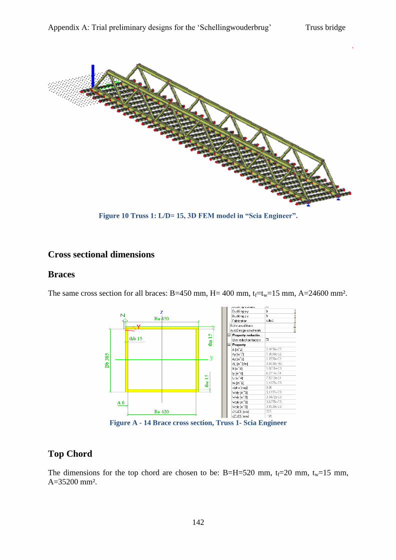
Appendix A: Trial preliminary designs for the ‘Schellingwouderbrug’ Truss bridge
142
Figure 10 Truss 1: L/D= 15, 3D FEM model in “Scia Engineer”.
Cross sectional dimensions
Braces
The same cross section for all braces: B=450 mm, H= 400 mm, tf=tw=15 mm, A=24600 mm².
Figure A - 14 Brace cross section, Truss 1- Scia Engineer
Top Chord
The dimensions for the top chord are chosen to be: B=H=520 mm, tf=20 mm, tw=15 mm,
A=35200 mm².
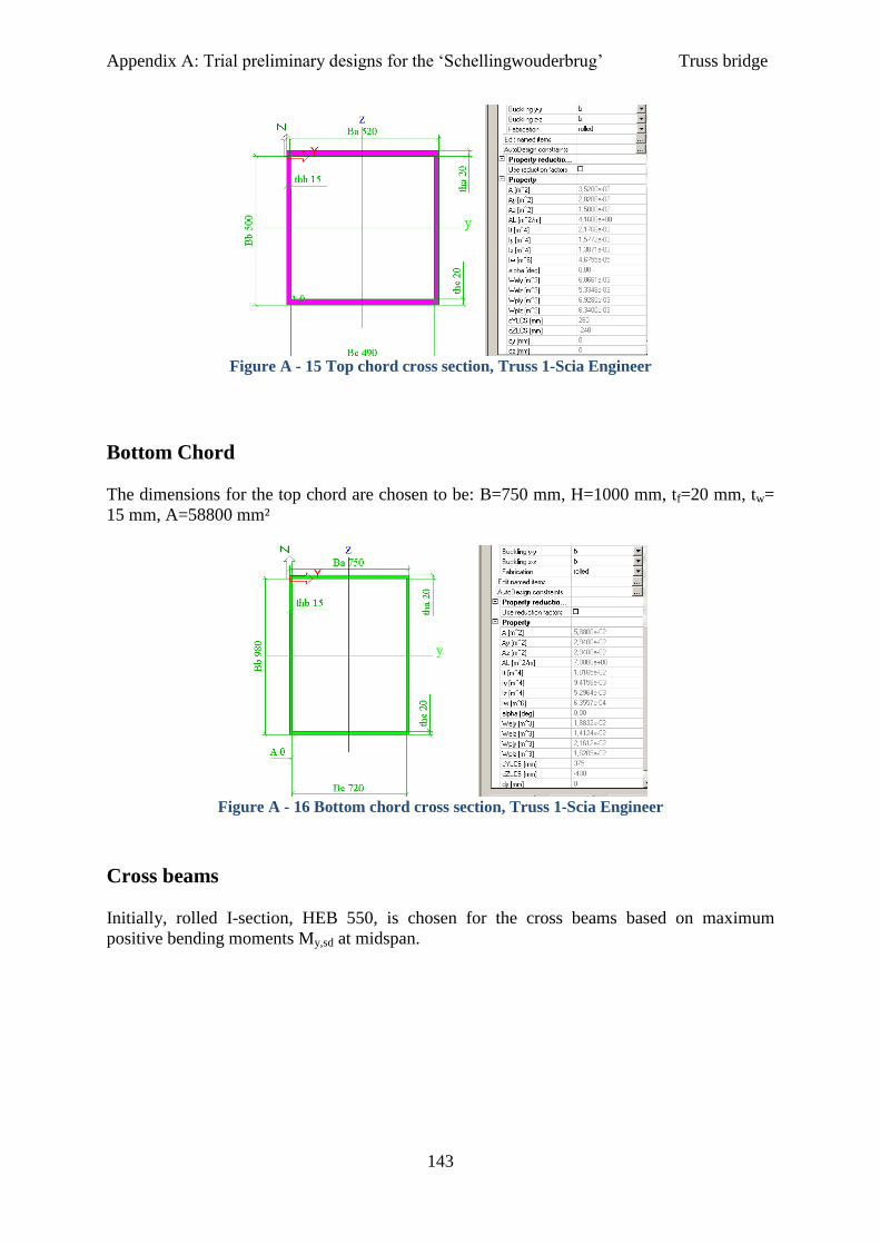
Appendix A: Trial preliminary designs for the ‘Schellingwouderbrug’ Truss bridge
143
Figure A - 15 Top chord cross section, Truss 1-Scia Engineer
Bottom Chord
The dimensions for the top chord are chosen to be: B=750 mm, H=1000 mm, tf=20 mm, tw=
15 mm, A=58800 mm²
Figure A - 16 Bottom chord cross section, Truss 1-Scia Engineer
Cross beams
Initially, rolled I-section, HEB 550, is chosen for the cross beams based on maximum
positive bending moments My,sd at midspan.
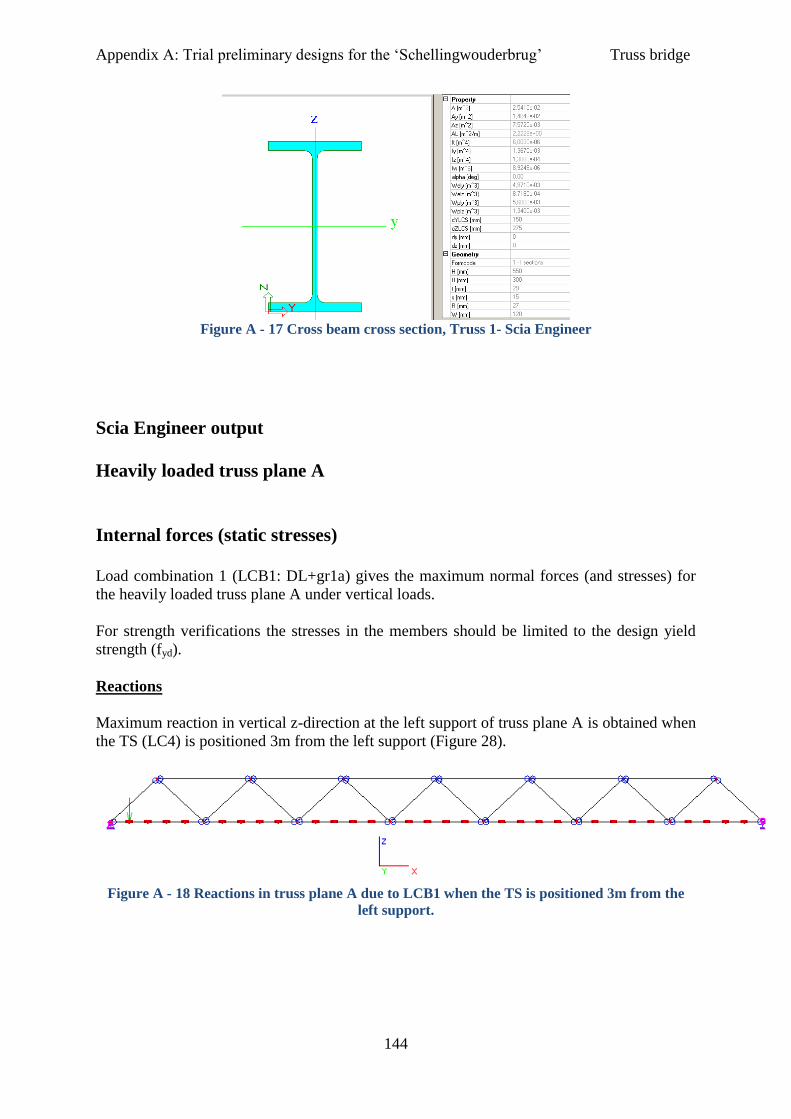
Appendix A: Trial preliminary designs for the ‘Schellingwouderbrug’ Truss bridge
144
Figure A - 17 Cross beam cross section, Truss 1- Scia Engineer
Scia Engineer output
Heavily loaded truss plane A
Internal forces (static stresses)
Load combination 1 (LCB1: DL+gr1a) gives the maximum normal forces (and stresses) for
the heavily loaded truss plane A under vertical loads.
For strength verifications the stresses in the members should be limited to the design yield
strength (fyd).
Reactions
Maximum reaction in vertical z-direction at the left support of truss plane A is obtained when
the TS (LC4) is positioned 3m from the left support (Figure 28).
Figure A - 18 Reactions in truss plane A due to LCB1 when the TS is positioned 3m from the
left support.
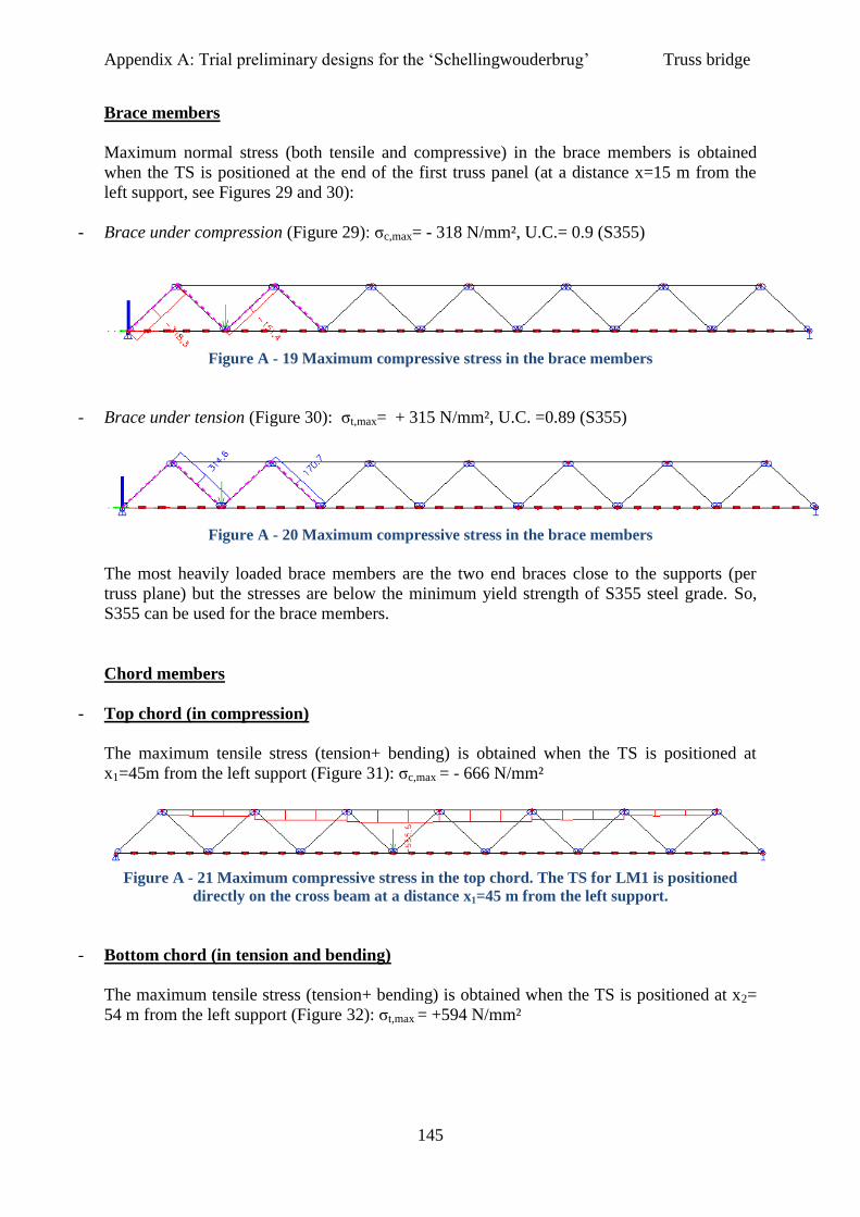
Appendix A: Trial preliminary designs for the ‘Schellingwouderbrug’ Truss bridge
145
Brace members
Maximum normal stress (both tensile and compressive) in the brace members is obtained
when the TS is positioned at the end of the first truss panel (at a distance x=15 m from the
left support, see Figures 29 and 30):
- Brace under compression (Figure 29): σc,max= - 318 N/mm², U.C.= 0.9 (S355)
Figure A - 19 Maximum compressive stress in the brace members
- Brace under tension (Figure 30): σt,max= + 315 N/mm², U.C. =0.89 (S355)
Figure A - 20 Maximum compressive stress in the brace members
The most heavily loaded brace members are the two end braces close to the supports (per
truss plane) but the stresses are below the minimum yield strength of S355 steel grade. So,
S355 can be used for the brace members.
Chord members
- Top chord (in compression)
The maximum tensile stress (tension+ bending) is obtained when the TS is positioned at
x1=45m from the left support (Figure 31): σc,max = - 666 N/mm²
Figure A - 21 Maximum compressive stress in the top chord. The TS for LM1 is positioned
directly on the cross beam at a distance x1=45 m from the left support.
- Bottom chord (in tension and bending)
The maximum tensile stress (tension+ bending) is obtained when the TS is positioned at x2=
54 m from the left support (Figure 32): σt,max = +594 N/mm²
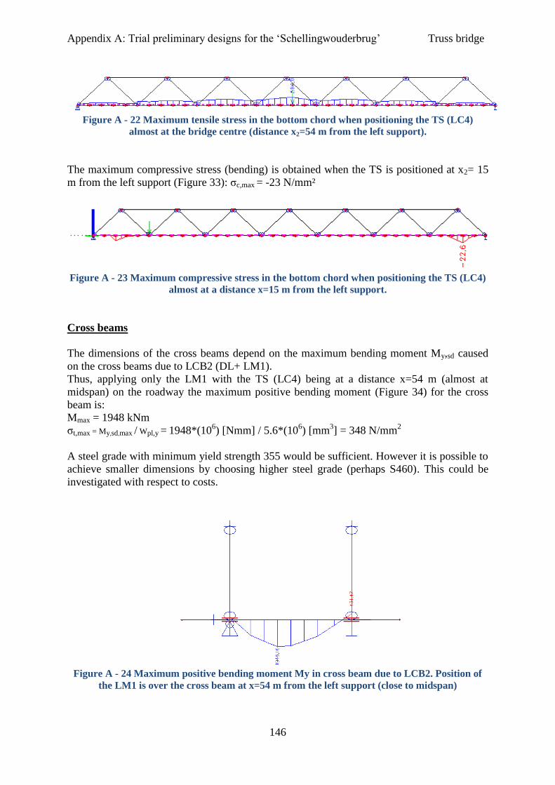
Appendix A: Trial preliminary designs for the ‘Schellingwouderbrug’ Truss bridge
146
Figure A - 22 Maximum tensile stress in the bottom chord when positioning the TS (LC4)
almost at the bridge centre (distance x2=54 m from the left support).
The maximum compressive stress (bending) is obtained when the TS is positioned at x2= 15
m from the left support (Figure 33): σc,max = -23 N/mm²
Figure A - 23 Maximum compressive stress in the bottom chord when positioning the TS (LC4)
almost at a distance x=15 m from the left support.
Cross beams
The dimensions of the cross beams depend on the maximum bending moment My,sd caused
on the cross beams due to LCB2 (DL+ LM1).
Thus, applying only the LM1 with the TS (LC4) being at a distance x=54 m (almost at
midspan) on the roadway the maximum positive bending moment (Figure 34) for the cross
beam is:
Mmax = 1948 kNm
σt,max = My,sd,max / Wpl,y = 1948*(106) [Nmm] / 5.6*(10
6) [mm
3] = 348 N/mm
2
A steel grade with minimum yield strength 355 would be sufficient. However it is possible to
achieve smaller dimensions by choosing higher steel grade (perhaps S460). This could be
investigated with respect to costs.
Figure A - 24 Maximum positive bending moment My in cross beam due to LCB2. Position of
the LM1 is over the cross beam at x=54 m from the left support (close to midspan)
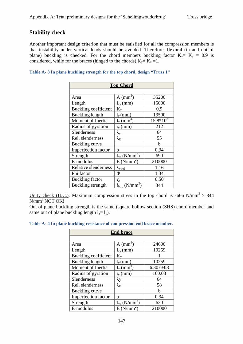
Appendix A: Trial preliminary designs for the ‘Schellingwouderbrug’ Truss bridge
147
Stability check
Another important design criterion that must be satisfied for all the compression members is
that instability under vertical loads should be avoided. Therefore, flexural (in and out of
plane) buckling is checked. For the chord members buckling factor Ky= Kz = 0.9 is
considered, while for the braces (hinged to the chords) Ky= Kz =1.
Table A- 3 In plane buckling strength for the top chord, design “Truss 1”
Unity check (U.C.): Maximum compression stress in the top chord is -666 N/mm2
> 344
N/mm2
NOT OK!
Out of plane buckling strength is the same (square hollow section (SHS) chord member and
same out of plane buckling length lz= ly).
Table A- 4 In plane buckling resistance of compression end brace member.
Top Chord
Area A (mm
2) 35200
Length Ly (mm) 15000
Buckling coefficient Ky 0,9
Buckling length ly (mm) 13500
Moment of Inertia Iy (mm4) 15.8*10
8
Radius of gyration iy (mm) 212
Slenderness λy 64
Rel. slenderness λE 55
Buckling curve b
Imperfection factor α 0,34
Strength fyd (N/mm2) 690
E-modulus E (N/mm2) 210000
Relative slenderness λy,rel 1,16
Phi factor Φ 1,34
Buckling factor χy 0,50
Buckling strength fb,rd (N/mm2) 344
End brace
Area A (mm
2) 24600
Length Ly (mm) 10259
Buckling coefficient Ky 1
Buckling length ly (mm) 10259
Moment of Inertia Iy (mm4) 6.30E+08
Radius of gyration iy (mm) 160.03
Slenderness λy 64
Rel. slenderness λE 58
Buckling curve b
Imperfection factor α 0.34
Strength fyd (N/mm2) 620
E-modulus E (N/mm2) 210000
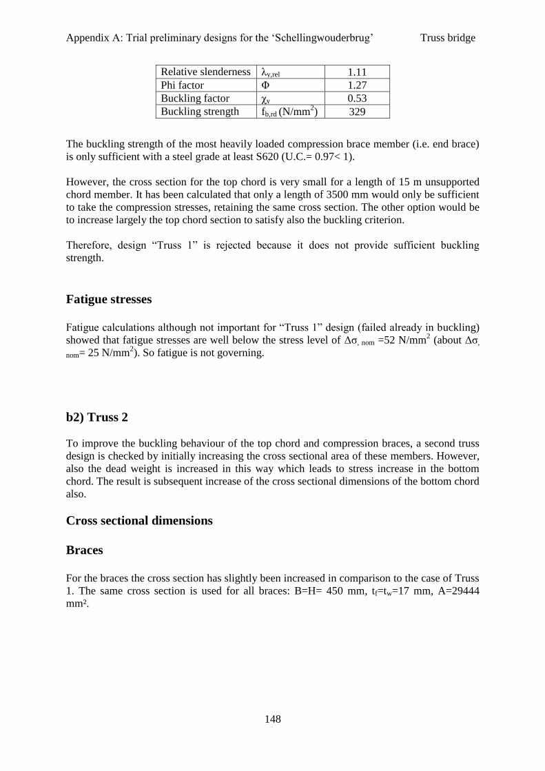
Appendix A: Trial preliminary designs for the ‘Schellingwouderbrug’ Truss bridge
148
The buckling strength of the most heavily loaded compression brace member (i.e. end brace)
is only sufficient with a steel grade at least S620 (U.C.= 0.97< 1).
However, the cross section for the top chord is very small for a length of 15 m unsupported
chord member. It has been calculated that only a length of 3500 mm would only be sufficient
to take the compression stresses, retaining the same cross section. The other option would be
to increase largely the top chord section to satisfy also the buckling criterion.
Therefore, design “Truss 1” is rejected because it does not provide sufficient buckling
strength.
Fatigue stresses
Fatigue calculations although not important for “Truss 1” design (failed already in buckling)
showed that fatigue stresses are well below the stress level of Δσ, nom =52 N/mm2 (about Δσ,
nom= 25 N/mm2). So fatigue is not governing.
b2) Truss 2
To improve the buckling behaviour of the top chord and compression braces, a second truss
design is checked by initially increasing the cross sectional area of these members. However,
also the dead weight is increased in this way which leads to stress increase in the bottom
chord. The result is subsequent increase of the cross sectional dimensions of the bottom chord
also.
Cross sectional dimensions
Braces
For the braces the cross section has slightly been increased in comparison to the case of Truss
1. The same cross section is used for all braces: B=H= 450 mm, tf=tw=17 mm, A=29444
mm².
Relative slenderness λy,rel 1.11
Phi factor Φ 1.27
Buckling factor χy 0.53
Buckling strength fb,rd (N/mm2) 329

Appendix A: Trial preliminary designs for the ‘Schellingwouderbrug’ Truss bridge
149
Figure A - 25 Brace cross section, Truss 2-Scia Engineer
In Truss 1 the brace cross section already satisfied the strength criterion. Now the cross
section is even bigger and can sufficiently take the resulting stresses which lie below 400
MPa. Thus only buckling and fatigue resistance should be again checked.
Buckling resistance of compressive brace members
Table A -5 In of plane buckling resistance of end brace, design “Truss 2”
Out of plane buckling strength is the same (i.e. square section, same buckling length).
The maximum stress in the compression brace member is -352 N/mm2. However, in order to
satisfy also the stability criterion, S620 is the minimum steel grade to be used for the heavily
loaded end braces (U.C: 352/369= 0.95 <1).
End brace
Area A (mm
2) 29444
Length Ly (mm) 10259
Buckling coefficient Ky 1
Buckling length ly (mm) 10259
Moment of Inertia Iy (mm4) 9.21E+08
Radius of gyration iy (mm) 176.86
Slenderness λy 58
Rel. slenderness λE 58
Buckling curve b
Imperfection factor α 0.34
Strength fyd (N/mm2) 620
E-modulus E (N/mm2) 210000
Relative slenderness λy,rel 1.00
Phi factor Φ 1.14
Buckling factor χy 0.59
Buckling strength fb,rd (N/mm2) 369

Appendix A: Trial preliminary designs for the ‘Schellingwouderbrug’ Truss bridge
150
For the rest compressive (and tensile) braces however the stresses are quite smaller and steel
grade S355 or S460 is sufficient for both strength and stability criteria.
Fatigue stresses in the brace members
Maximum fatigue stress in the critical brace (brace 2 connection with bottom chord) is Δσ, nom
= 19 N/mm2
<< 52 N/mm2.
Thus, this cross section provides an acceptable solution for the braces in design “Truss 2”, as
it satisfied all three design criteria (i.e. strength, stability, fatigue).
Top Chord
Strength
The dimensions for the top chord have been initially increased (Figure 27) to satisfy the
strength criterion (i.e. increasing the bracing dimensions increased the dead weight of the
structure, thus increased the stresses in the top chord).
B=650, H=600 mm, tf=26 mm, tw=23 mm, A=59008 mm². In this case, sufficient strength can
be obtained using at least steel grade S550 for the heavily loaded chord parts.
Figure A - 26 Top chord cross section, Truss 2- Scia Engineer
Buckling resistance of top (compression) chord
The top chord is subject to compression and unfortunately, global buckling is again
governing in this design also for a length of 15 m (even a steel grade S690 is not sufficient
for the stresses in the chord).
Thus, alternatives are considered in order to deal with stability problems. These in general
include:
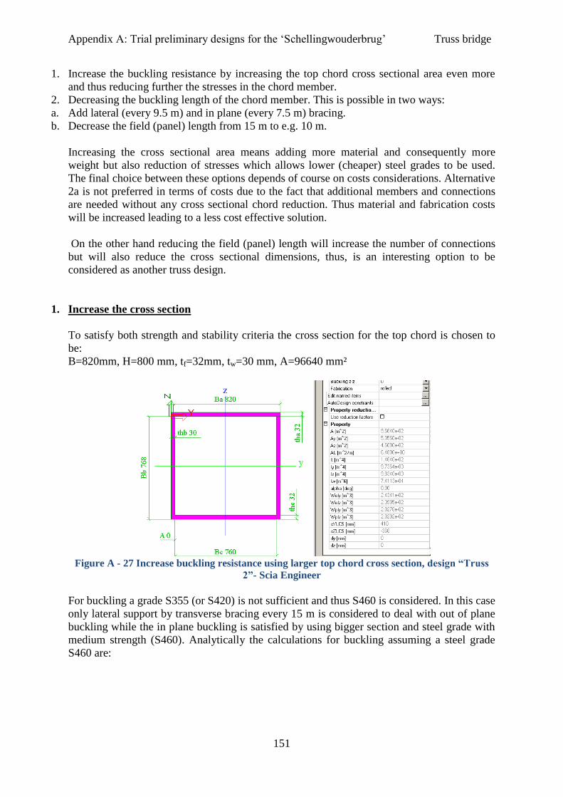
Appendix A: Trial preliminary designs for the ‘Schellingwouderbrug’ Truss bridge
151
1. Increase the buckling resistance by increasing the top chord cross sectional area even more
and thus reducing further the stresses in the chord member.
2. Decreasing the buckling length of the chord member. This is possible in two ways:
a. Add lateral (every 9.5 m) and in plane (every 7.5 m) bracing.
b. Decrease the field (panel) length from 15 m to e.g. 10 m.
Increasing the cross sectional area means adding more material and consequently more
weight but also reduction of stresses which allows lower (cheaper) steel grades to be used.
The final choice between these options depends of course on costs considerations. Alternative
2a is not preferred in terms of costs due to the fact that additional members and connections
are needed without any cross sectional chord reduction. Thus material and fabrication costs
will be increased leading to a less cost effective solution.
On the other hand reducing the field (panel) length will increase the number of connections
but will also reduce the cross sectional dimensions, thus, is an interesting option to be
considered as another truss design.
1. Increase the cross section
To satisfy both strength and stability criteria the cross section for the top chord is chosen to
be:
B=820mm, H=800 mm, tf=32mm, tw=30 mm, A=96640 mm²
Figure A - 27 Increase buckling resistance using larger top chord cross section, design “Truss
2”- Scia Engineer
For buckling a grade S355 (or S420) is not sufficient and thus S460 is considered. In this case
only lateral support by transverse bracing every 15 m is considered to deal with out of plane
buckling while the in plane buckling is satisfied by using bigger section and steel grade with
medium strength (S460). Analytically the calculations for buckling assuming a steel grade
S460 are:
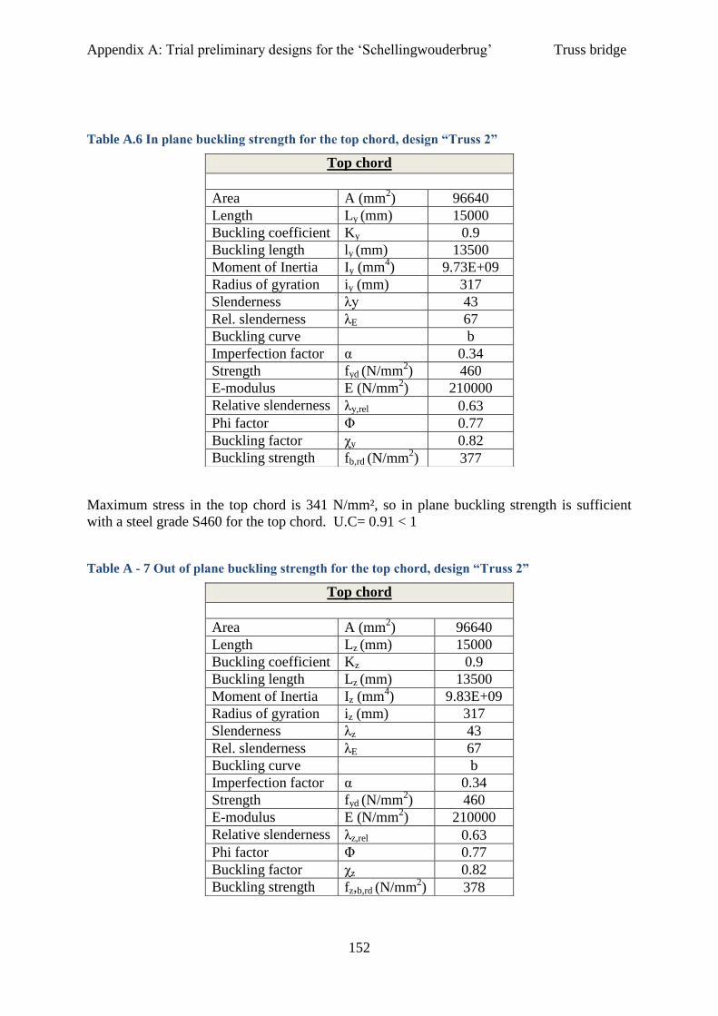
Appendix A: Trial preliminary designs for the ‘Schellingwouderbrug’ Truss bridge
152
Table A.6 In plane buckling strength for the top chord, design “Truss 2”
Maximum stress in the top chord is 341 N/mm², so in plane buckling strength is sufficient
with a steel grade S460 for the top chord. U.C= 0.91 < 1
Table A - 7 Out of plane buckling strength for the top chord, design “Truss 2”
Top chord
Area A (mm
2) 96640
Length Ly (mm) 15000
Buckling coefficient Ky 0.9
Buckling length ly (mm) 13500
Moment of Inertia Iy (mm4) 9.73E+09
Radius of gyration iy (mm) 317
Slenderness λy 43
Rel. slenderness λE 67
Buckling curve b
Imperfection factor α 0.34
Strength fyd (N/mm2) 460
E-modulus E (N/mm2) 210000
Relative slenderness λy,rel 0.63
Phi factor Φ 0.77
Buckling factor χy 0.82
Buckling strength fb,rd (N/mm2) 377
Top chord
Area A (mm
2) 96640
Length Lz (mm) 15000
Buckling coefficient Kz 0.9
Buckling length Lz (mm) 13500
Moment of Inertia Iz (mm4) 9.83E+09
Radius of gyration iz (mm) 317
Slenderness λz 43
Rel. slenderness λE 67
Buckling curve b
Imperfection factor α 0.34
Strength fyd (N/mm2) 460
E-modulus E (N/mm2) 210000
Relative slenderness λz,rel 0.63
Phi factor Φ 0.77
Buckling factor χz 0.82
Buckling strength fz,b,rd (N/mm2) 378
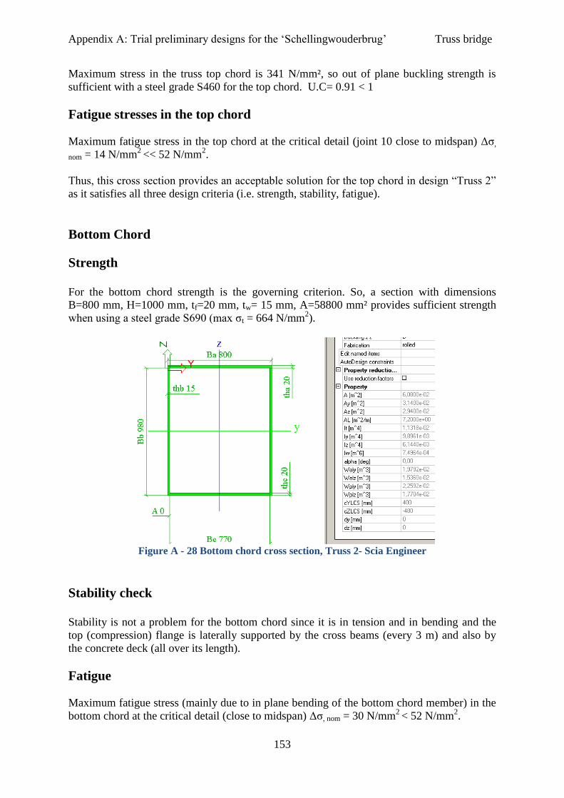
Appendix A: Trial preliminary designs for the ‘Schellingwouderbrug’ Truss bridge
153
Maximum stress in the truss top chord is 341 N/mm², so out of plane buckling strength is
sufficient with a steel grade S460 for the top chord. U.C= 0.91 < 1
Fatigue stresses in the top chord
Maximum fatigue stress in the top chord at the critical detail (joint 10 close to midspan) Δσ,
nom = 14 N/mm2
<< 52 N/mm2.
Thus, this cross section provides an acceptable solution for the top chord in design “Truss 2”
as it satisfies all three design criteria (i.e. strength, stability, fatigue).
Bottom Chord
Strength
For the bottom chord strength is the governing criterion. So, a section with dimensions
B=800 mm, H=1000 mm, tf=20 mm, tw= 15 mm, A=58800 mm² provides sufficient strength
when using a steel grade S690 (max σt = 664 N/mm2).
Figure A - 28 Bottom chord cross section, Truss 2- Scia Engineer
Stability check
Stability is not a problem for the bottom chord since it is in tension and in bending and the
top (compression) flange is laterally supported by the cross beams (every 3 m) and also by
the concrete deck (all over its length).
Fatigue
Maximum fatigue stress (mainly due to in plane bending of the bottom chord member) in the
bottom chord at the critical detail (close to midspan) Δσ, nom = 30 N/mm2 < 52 N/mm
2.

Appendix A: Trial preliminary designs for the ‘Schellingwouderbrug’ Truss bridge
154
Thus, this cross section provides an acceptable solution for the bottom chord in design “Truss
2” as it satisfied all three design criteria (i.e. strength, stability, fatigue).
Cross beams
For the cross beam I- section profile fabricated by welded plates is chosen. Fabricated
sections are generally less economic than standardized profiles but they can be tailored for
the specific design.
The required height to take over the vertical loads is much smaller (about 600 mm).
However, a height of 1000 m is chosen as to ease the fabrication of the connection with the
bottom chord. Based on resulting stresses on the cross beams (below 100 N/mm2), a low steel
grade e.g. S235 can be used for the cross beams.
Figure A - 29 Cross beam cross section, Truss 2-Scia Engineer
Stability
Stability is not a problem for the cross beam since the top (compression) flange is laterally
supported by the concrete deck all over its length.
Fatigue stresses in the cross beam
Maximum fatigue stress in the cross beam at the critical detail (joint at x= 15 m) Δσ, nom = 36
N/mm2
< 52 N/mm2.
Thus, this cross section provides an acceptable solution for the bottom chord in design Truss
2 as it satisfied all three design criteria (i.e. strength, stability, fatigue).

Appendix A: Trial preliminary designs for the ‘Schellingwouderbrug’ Truss bridge
155
Result
For the design “Truss 2” satisfies the structural requirements with respect to strength, fatigue
and stability of the truss members. The total self-weight of the steel structure is 414 tn.
b3) Truss 3
This design differs from the other two in that the field length is now reduced to 10.5 m
instead of 15 m that it was initially. This has been done to improve buckling resistance of
compression members. Also the bracing system (laterally) is assumed to be closer oriented
(every 10.5 m).
2.b) Decreasing the buckling length of the chord member
In order to reduce the buckling length of the top chord (alternative 2b above) a new truss
design (Truss 3, Figure 5.38) is made considering smaller field (panel) length and thus more
truss panels and smaller unsupported (in plane and laterally) chord length. The geometrical
parameters are chosen to be in this case:
L= 105 m
Li= 10.5 m L/D= 15
D= 7 m
Cross beams c.t.c distance = 3 m
Loads on the cross beams: Edge beams: q (kN/m2)* 1.5 m (influence length)
All the others: q (kN/m2)* 3 m (influence length)
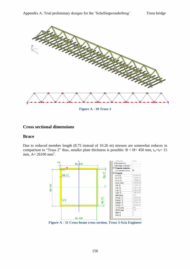
Appendix A: Trial preliminary designs for the ‘Schellingwouderbrug’ Truss bridge
156
Figure A - 30 Truss 3
Cross sectional dimensions
Brace
Due to reduced member length (8.75 instead of 10.26 m) stresses are somewhat reduces in
comparison to “Truss 2” thus, smaller plate thickness is possible: B = H= 450 mm, tw=tf= 15
mm, A= 26100 mm2.
Figure A - 31 Cross beam cross section, Truss 3-Scia Engineer

Appendix A: Trial preliminary designs for the ‘Schellingwouderbrug’ Truss bridge
157
Buckling calculations for compression brace
Table A - 8 In plane buckling strength end brace, design “Truss 3”
Maximum stress in the compression brace is 312 N/mm², so in plane buckling strength is
sufficient with steel grade at least S460, U.C= 0.90 < 1 . For out of plane the same strength
applies (square brace section).
Table A - 9 Out of plane buckling strength end brace, design “Truss 3”
End brace
Area A (mm
2) 26100
Length Ly (mm) 8750
Buckling coefficient Ky 1
Buckling length ly (mm) 8750
Moment of Inertia Iy (mm4) 8,24E+08
Radius of gyration iy (mm) 177,68
Slenderness λy 49
Rel. slenderness λE 67
Buckling curve b
Imperfection factor α 0,34
Strength fyd (N/mm2) 460
E-modulus E (N/mm2) 210000
Relative slenderness λy,rel 0,73
Phi factor Φ 0,86
Buckling factor χy 0,76
Buckling strength fy,b,rd (N/mm2) 352
Rest compression braces
Area A (mm
2) 26100
Length Ly (mm) 8750
Buckling coefficient Ky 1
Buckling length ly (mm) 8750
Moment of Inertia Iy (mm4) 8,24E+08
Radius of gyration iy (mm) 177,68
Slenderness λy 49
Rel. slenderness λE 76
Buckling curve b
Imperfection factor α 0,34
Strength fyd (N/mm2) 355
E-modulus E (N/mm2) 210000
Relative slenderness λy,rel 0,64
Phi factor Φ 0,78
Buckling factor χy 0,81
Buckling strength fy,b,rd (N/mm2) 289
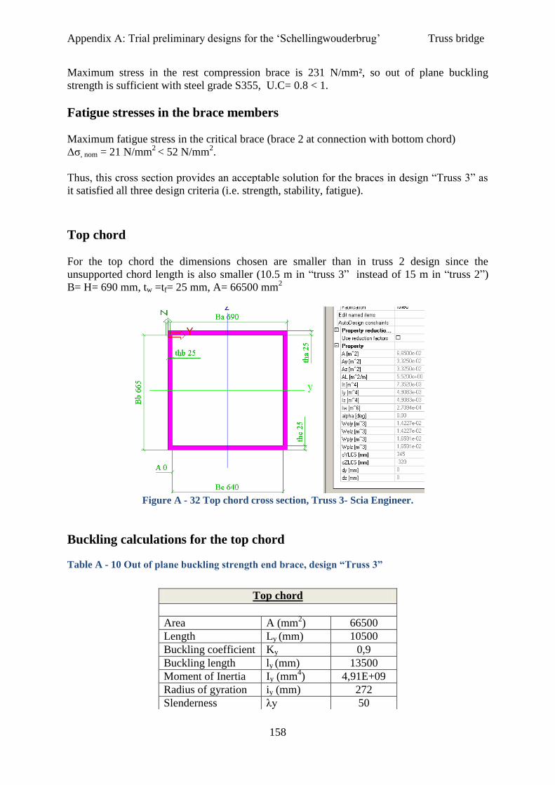
Appendix A: Trial preliminary designs for the ‘Schellingwouderbrug’ Truss bridge
158
Maximum stress in the rest compression brace is 231 N/mm², so out of plane buckling
strength is sufficient with steel grade S355, U.C= 0.8 < 1.
Fatigue stresses in the brace members
Maximum fatigue stress in the critical brace (brace 2 at connection with bottom chord)
Δσ, nom = 21 N/mm2
< 52 N/mm2.
Thus, this cross section provides an acceptable solution for the braces in design “Truss 3” as
it satisfied all three design criteria (i.e. strength, stability, fatigue).
Top chord
For the top chord the dimensions chosen are smaller than in truss 2 design since the
unsupported chord length is also smaller (10.5 m in “truss 3” instead of 15 m in “truss 2”)
B= H= 690 mm, tw =tf= 25 mm, A= 66500 mm2
Figure A - 32 Top chord cross section, Truss 3- Scia Engineer.
Buckling calculations for the top chord
Table A - 10 Out of plane buckling strength end brace, design “Truss 3”
Top chord
Area A (mm
2) 66500
Length Ly (mm) 10500
Buckling coefficient Ky 0,9
Buckling length ly (mm) 13500
Moment of Inertia Iy (mm4) 4,91E+09
Radius of gyration iy (mm) 272
Slenderness λy 50

Appendix A: Trial preliminary designs for the ‘Schellingwouderbrug’ Truss bridge
159
Maximum stress in the truss top chord is 425 N/mm², so in plane buckling strength is
sufficient with a steel grade S690 for the top chord. U.C= 0.94 < 1. The out of buckling
strength is the same (square section, same in and out of plane buckling length).
Fatigue stresses in the top chord
Maximum fatigue stress in the top chord at the critical detail (bottom fibre in joint 10 close to
midspan) Δσ, nom = 21 N/mm2
<< 52 N/mm2.
Thus, this cross section provides an acceptable solution for the top chord in design “Truss 3”
as it satisfied all three design criteria (i.e. strength, stability, fatigue).
Bottom chord
For the bottom chord strength is the governing criterion. So, a section with dimensions B=H
=700 mm, tw= 15 mm, tf= 20 mm A=47800 mm² provides sufficient strength when using a
steel grade S690 (max σt = 630 N/mm2, U.C. =0.91).
Figure A - 33 Bottom chord cross section, Truss 3- Scia Engineer
Rel. slenderness λE 55
Buckling curve b
Imperfection factor α 0,34
Strength fyd (N/mm2) 690
E-modulus E (N/mm2) 210000
Relative slenderness λy,rel 0,91
Phi factor Φ 1,03
Buckling factor χy 0,66
Buckling strength fb,rd (N/mm2) 453
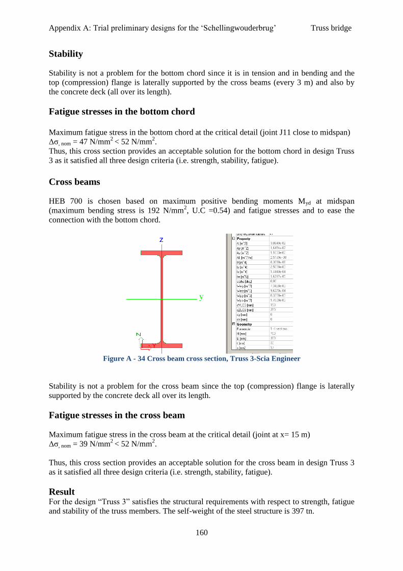
Appendix A: Trial preliminary designs for the ‘Schellingwouderbrug’ Truss bridge
160
Stability
Stability is not a problem for the bottom chord since it is in tension and in bending and the
top (compression) flange is laterally supported by the cross beams (every 3 m) and also by
the concrete deck (all over its length).
Fatigue stresses in the bottom chord
Maximum fatigue stress in the bottom chord at the critical detail (joint J11 close to midspan)
Δσ, nom = 47 N/mm2
< 52 N/mm2.
Thus, this cross section provides an acceptable solution for the bottom chord in design Truss
3 as it satisfied all three design criteria (i.e. strength, stability, fatigue).
Cross beams
HEB 700 is chosen based on maximum positive bending moments Myd at midspan
(maximum bending stress is 192 N/mm2, U.C =0.54) and fatigue stresses and to ease the
connection with the bottom chord.
Figure A - 34 Cross beam cross section, Truss 3-Scia Engineer
Stability is not a problem for the cross beam since the top (compression) flange is laterally
supported by the concrete deck all over its length.
Fatigue stresses in the cross beam
Maximum fatigue stress in the cross beam at the critical detail (joint at x= 15 m)
Δσ, nom = 39 N/mm2
< 52 N/mm2.
Thus, this cross section provides an acceptable solution for the cross beam in design Truss 3
as it satisfied all three design criteria (i.e. strength, stability, fatigue).
Result For the design “Truss 3” satisfies the structural requirements with respect to strength, fatigue
and stability of the truss members. The self-weight of the steel structure is 397 tn.
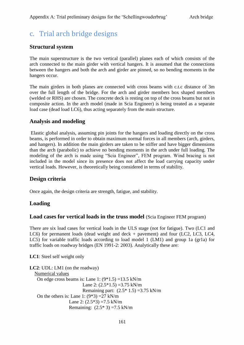
Appendix A: Trial preliminary designs for the ‘Schellingwouderbrug’ Arch bridge
161
c. Trial arch bridge designs
Structural system
The main superstructure is the two vertical (parallel) planes each of which consists of the
arch connected to the main girder with vertical hangers. It is assumed that the connections
between the hangers and both the arch and girder are pinned, so no bending moments in the
hangers occur.
The main girders in both planes are connected with cross beams with c.t.c distance of 3m
over the full length of the bridge. For the arch and girder members box shaped members
(welded or RHS) are chosen. The concrete deck is resting on top of the cross beams but not in
composite action. In the arch model (made in Scia Engineer) is being treated as a separate
load case (dead load LC6), thus acting separately from the main structure.
Analysis and modeling
Elastic global analysis, assuming pin joints for the hangers and loading directly on the cross
beams, is performed in order to obtain maximum normal forces in all members (arch, girders,
and hangers). In addition the main girders are taken to be stiffer and have bigger dimensions
than the arch (parabolic) to achieve no bending moments in the arch under full loading. The
modeling of the arch is made using “Scia Engineer”, FEM program. Wind bracing is not
included in the model since its presence does not affect the load carrying capacity under
vertical loads. However, is theoretically being considered in terms of stability.
Design criteria
Once again, the design criteria are strength, fatigue, and stability.
Loading
Load cases for vertical loads in the truss model (Scia Engineer FEM program)
There are six load cases for vertical loads in the ULS stage (not for fatigue). Two (LC1 and
LC6) for permanent loads (dead weight and deck + pavement) and four (LC2, LC3, LC4,
LC5) for variable traffic loads according to load model 1 (LM1) and group 1a (gr1a) for
traffic loads on roadway bridges (EN 1991-2: 2003). Analytically these are:
LC1: Steel self weight only
LC2: UDL: LM1 (on the roadway)
Numerical values
On edge cross beams is: Lane 1: (9*1.5) =13.5 kN/m
Lane 2: (2.5*1.5) =3.75 kN/m
Remaining part: (2.5* 1.5) =3.75 kN/m
On the others is: Lane 1: (9*3) =27 kN/m
Lane 2: (2.5*3) =7.5 kN/m
Remaining: (2.5* 3) =7.5 kN/m
Appendix A: Trial preliminary designs for the ‘Schellingwouderbrug’ Arch bridge
162
LC3: qlf: cycle/foot path load (combination value,ψ0=0.40) on the left side of the bridge
only.
Numerical values:
On edge cross beams is: 0.40*2.89*1.5=1.73 kN/m
On the others is: 0.40*2.89*3= 3.47 kN/m
LC4: TS: LM1
Numerical values:
Lane 1: Qs,k,1= 300 kN (axle load)
Lane 2: Qs,k,2= 200 kN (axle load)
LC5: qlf: cycle/foot path load (combination value) on both sides.
Numerical values:
On edge cross beams is: 0.40*2.89*1.5=1.73 kN/m
On the others is: 0.40*2.89*3= 3.47 kN/m
LC6: Deck + pavement: Assume normal weight concrete deck [EN 1991-1-1].
Deck: Normal weight concrete with thickness t= 240 mm and density γ= 25 kN/m³
(assumed).
Pavement: Mastic asphalt: t= 8 mm and density γ= 20 kN/m³.
For fatigue load model 3 (FLM3) is applied to obtain an indication on maximum and
minimum stress values caused by traffic.
LC7: FLM3 according to the EN 1991-2:2003 (see Figure 4).
11.1.1.1.1 ................................................................................................... Load Combinations
One load combinations for vertical loads is considered as the most critical in the ULS stage.
LCB1: 1.35* LC1+ 1.35* LC2+1.35*LC3+ 1.35*LC4, (DL + gr1a, cycle load only on one
side of the bridge).
The most critical load cases in case of an arch bridge are full loading and full loading at half
the length (see also Figure 5.46 a) and b) respectively). The TS is positioned at half the length
of the UDL.
Full loading causes the maximum normal forces (compressive for the arch and tensile for the
girders) and the maximum normal forces and stresses (tensile) in the hangers.
Full loading over half the length causes maximum bending moments and maximum normal
stresses (bending + normal force) in the arch and in the girders.
Stability
The buckling length of the unsupported arch member is small (about 10 m) in comparison to
the case of the truss bridge and the cross sectional area for the arch is quite bigger in
comparison to the compression chord for the truss. Therefore, is assumed that buckling
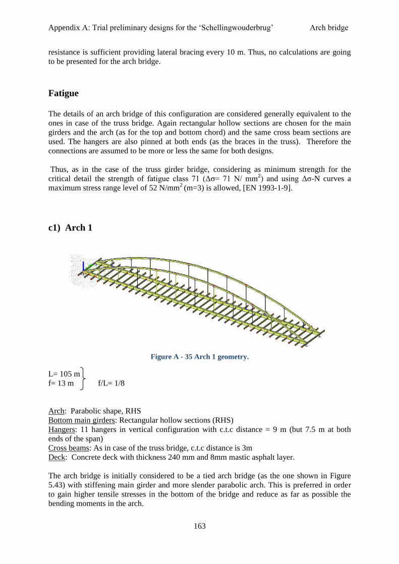
Appendix A: Trial preliminary designs for the ‘Schellingwouderbrug’ Arch bridge
163
resistance is sufficient providing lateral bracing every 10 m. Thus, no calculations are going
to be presented for the arch bridge.
Fatigue
The details of an arch bridge of this configuration are considered generally equivalent to the
ones in case of the truss bridge. Again rectangular hollow sections are chosen for the main
girders and the arch (as for the top and bottom chord) and the same cross beam sections are
used. The hangers are also pinned at both ends (as the braces in the truss). Therefore the
connections are assumed to be more or less the same for both designs.
Thus, as in the case of the truss girder bridge, considering as minimum strength for the
critical detail the strength of fatigue class 71 (Δσ= 71 N/ mm2) and using Δσ-N curves a
maximum stress range level of 52 N/mm2
(m=3) is allowed, [EN 1993-1-9].
c1) Arch 1
Figure A - 35 Arch 1 geometry.
L= 105 m
f= 13 m f/L= 1/8
Arch: Parabolic shape, RHS
Bottom main girders: Rectangular hollow sections (RHS)
Hangers: 11 hangers in vertical configuration with c.t.c distance = 9 m (but 7.5 m at both
ends of the span)
Cross beams: As in case of the truss bridge, c.t.c distance is 3m
Deck: Concrete deck with thickness 240 mm and 8mm mastic asphalt layer.
The arch bridge is initially considered to be a tied arch bridge (as the one shown in Figure
5.43) with stiffening main girder and more slender parabolic arch. This is preferred in order
to gain higher tensile stresses in the bottom of the bridge and reduce as far as possible the
bending moments in the arch.
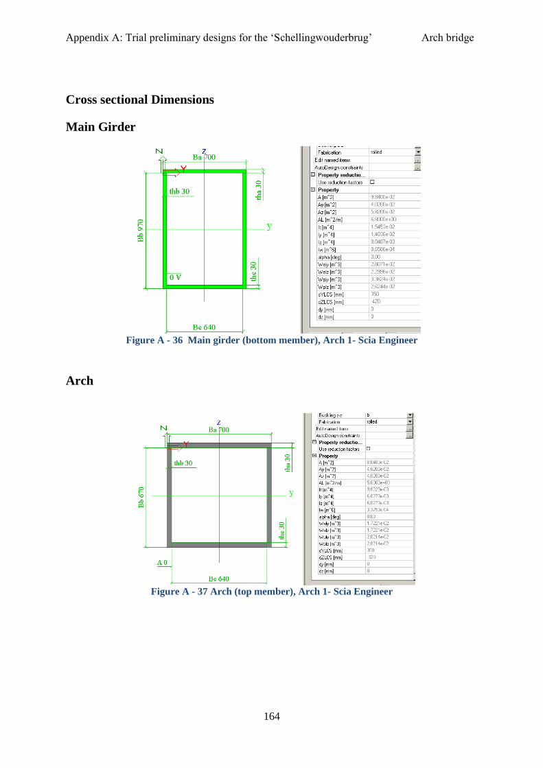
Appendix A: Trial preliminary designs for the ‘Schellingwouderbrug’ Arch bridge
164
Cross sectional Dimensions
Main Girder
Figure A - 36 Main girder (bottom member), Arch 1- Scia Engineer
Arch
Figure A - 37 Arch (top member), Arch 1- Scia Engineer

Appendix A: Trial preliminary designs for the ‘Schellingwouderbrug’ Arch bridge
165
Hangers
Figure A - 38 Vertical hangers, Arch 1- Scia Engineer
Stresses
Normal stresses
Arch: max σ = - 405 N/mm2 (under half-length loading)
Girder: max σ = + 442 N/mm2 (under half-length loading)
Hangers: max σ =+ 473 N/mm2
(in hanger 6-center-, under full loading and TS in midspan)
Fatigue stresses (top fiber)
Arch: max Δσ = 57 N/mm2 (at about L/4)
Girder: max Δσ = 83N/mm2
(at about L/4)
Hangers: max Δσ = 32N/mm2
(in hanger 5 and 6-center-)
Not sufficient. Very high fatigue stresses.
What happens when only decreasing the arch rise at 10 m?
L= 105 m
f= 10 m f/L= 1/10
Stresses
Normal stresses
Arch: max σ = - 458 N/mm2 (under half-length loading)
Girder: max σ = +488 N/mm2
(under half-length loading)
Hangers: max σ = +480 N/mm2
(in hanger 6-center-, under full loading)
Fatigue stresses (top fiber)
Arch: max Δσ = 57 N/mm2 (at about L/4)

Appendix A: Trial preliminary designs for the ‘Schellingwouderbrug’ Arch bridge
166
Girder: max Δσ = 83N/mm2
(at about L/4)
Hangers: max Δσ = 33N/mm2
(in hanger 5 and 6-center-)
It does not improve the fatigue stresses at all but increases the stresses in the members to
allow for use of higher steel grades. However fatigue is still the governing factor.
As a next step bigger arch rise decrease (f= 10 m) with simultaneous increase of the cross
sectional dimensions for the main girders is attempted.
The girder cross section becomes now:
Figure A - 39 New girder cross section for “Arch 1”, with f= 10 m.
Stresses
Normal stresses
Arch: max σ = - 424 N/mm2 (under half-length loading)
Girder: max σ = +437 N/mm2
(under half-length loading)
Hangers: max σ = +470 N/mm2
(in hanger 6-center-, under full loading)
Fatigue stresses (top fiber)
Arch: max Δσ = 47 N/mm2 (at about L/4)
Girder: max Δσ = 72 N/mm2
(at about L/4)
Hangers: max Δσ = 28 N/mm2 (in hanger 5 and 6-center-)
Fatigue stresses are still quite high, caused mainly by bending. So let’s try to increase the
section modulus of the cross section by again increasing the height of the girder from 1080
mm to 1500 mm.

Appendix A: Trial preliminary designs for the ‘Schellingwouderbrug’ Arch bridge
167
Figure A - 40 Increased main girder height, even more, to deal with high fatigue stresses mainly
caused by bending, Arch 1 when f=10 m.
Stresses
Normal stresses
Arch: max σ = - 353 N/mm2 (under half-length loading)
Girder: max σ = +348 N/mm2
(under half-length loading)
Hangers: max σ = +450 N/mm2
(in hanger 6-center-, under full loading)
Fatigue stresses (top fiber)
Arch: max Δσ = 26 N/mm2 (at about L/4)
Girder: max Δσ = 53 N/mm2
(at about L/4)
Hangers: max Δσ = 22 N/mm2
(in hanger 5 and 6-center-)
Increasing the girder cross section the fatigue stresses are decreased but also the static
stresses decrease and that does not favor the use of high strength steel grades (e.g. S690).
However the stiffness of the arch in this case is bigger than the stiffness of the main girder in
contrast to an arch type with a stiffening girder proposed at the beginning.
What about changing the c.t.c distance of the hangers to reduce the bending moments in the
main girders? This has been done considering another design namely, “Arch 2”.
C2) Arch 2
L= 105 m
f= 13 m f/L= 1/8
Arch: Parabolic shape, RHS
Bottom main stiffening girders: RHS sections
Hangers: 14 hangers in vertical configuration with c.t.c distance = 7.5 m.
Cross beams: As in case of the truss bridge, c.t.c distance is 3m
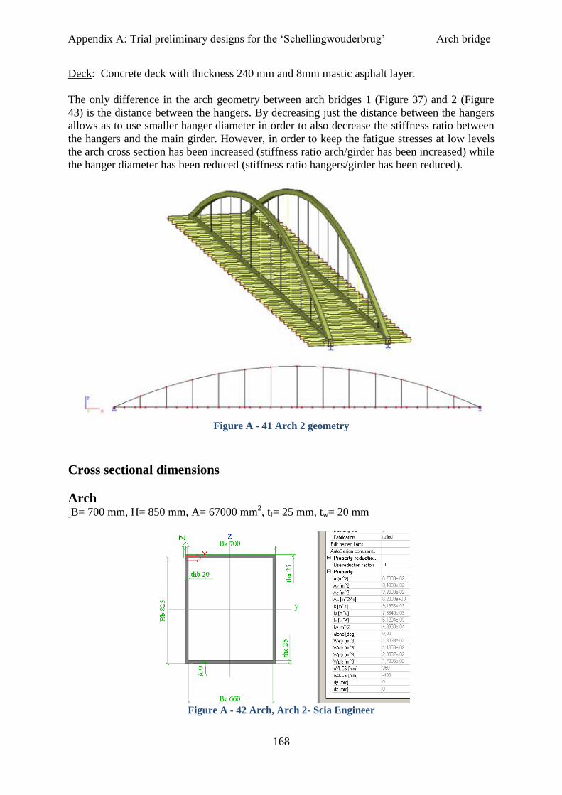
Appendix A: Trial preliminary designs for the ‘Schellingwouderbrug’ Arch bridge
168
Deck: Concrete deck with thickness 240 mm and 8mm mastic asphalt layer.
The only difference in the arch geometry between arch bridges 1 (Figure 37) and 2 (Figure
43) is the distance between the hangers. By decreasing just the distance between the hangers
allows as to use smaller hanger diameter in order to also decrease the stiffness ratio between
the hangers and the main girder. However, in order to keep the fatigue stresses at low levels
the arch cross section has been increased (stiffness ratio arch/girder has been increased) while
the hanger diameter has been reduced (stiffness ratio hangers/girder has been reduced).
Figure A - 41 Arch 2 geometry
Cross sectional dimensions
Arch
B= 700 mm, H= 850 mm, A= 67000 mm2, tf= 25 mm, tw= 20 mm
Figure A - 42 Arch, Arch 2- Scia Engineer

Appendix A: Trial preliminary designs for the ‘Schellingwouderbrug’ Arch bridge
169
Main girder B= 800 mm, H= 1400 mm, A= 128400 mm
2, tf= 30 mm, tw= 30 mm
Figure A - 43 Main Girder, Arch 2- Scia Engineer
Hangers D= 48 mm, A=1809 mm
2
Figure A - 44 Hangers (RD55), Arch 2- Scia Engineer
Stresses
Normal stresses
Arch: max σ = - 363 N/mm2 (under half-length loading)

Appendix A: Trial preliminary designs for the ‘Schellingwouderbrug’ Arch bridge
170
Girder: max σ = +321 N/mm2
(under half-length loading)
Hangers: max σ = +565 N/mm2
(in hanger 6-center-, under full loading)
Fatigue stresses (top fiber)
Arch: max Δσ = 27 N/mm2 (at about L/4)
Girder: max Δσ = 38 N/mm2
(bottom fiber at about L/4)
Hangers: max Δσ = 22 N/mm2 (in hanger 6-center-)
The fatigue stresses have been reduced to acceptable levels but the static stresses in the arch
and in the main girders are very small. However, the hangers (heavily loaded ones) can be
made out of high strength steel S690.
Trying again altering the cross sectional dimensions and recalculating normal and fatigue
stresses.
Main Girder
Figure A - 45 Main Girder, Arch 2- Scia Engineer
Arch
Figure A - 46 Figure 11 Arch, Arch 2- Scia Engineer

Appendix A: Trial preliminary designs for the ‘Schellingwouderbrug’ Arch bridge
171
Hangers
Figure A - 47 Hangers, Arch 2- Scia Engineer
Stresses
Normal stresses
Arch: max σ = - 473 N/mm2 (under half-length loading)
Girder: max σ = +536 N/mm2
(under half-length loading)
Hangers: max σ = +637 N/mm2
(in hanger 6-center-, under full loading)
Fatigue stresses (top fiber)
Arch: max Δσ = 85 N/mm2 (at about L/4)
Girder: max Δσ = 93 N/mm2
(at about L/4)
Hangers: max Δσ = 54 N/mm2 (in hanger 5 and 6-center-)
The fatigue stresses remain high. Once again, the cross sections are changed to deal with (try
to reduce) fatigue stresses. In addition c.t.c distance between the hangers is reduced to 6 m
(Figure 123).
Figure A - 48 Arch 2 with c.t.c distance between hangers 6 m
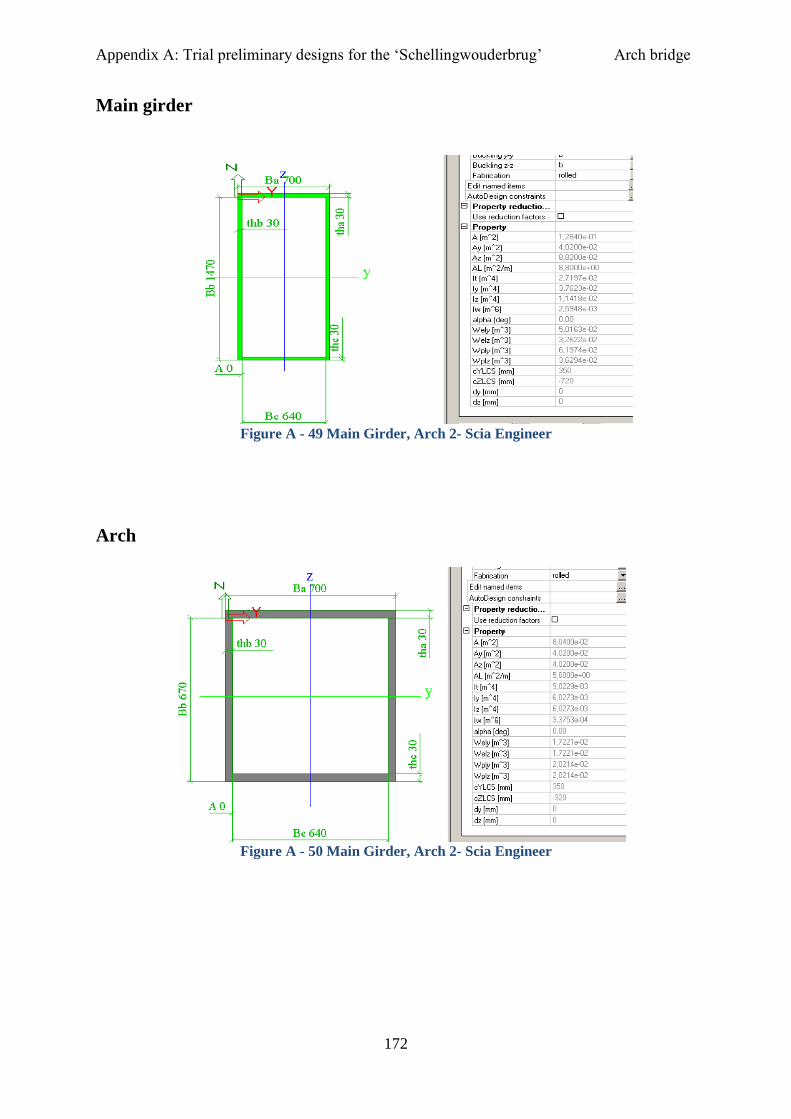
Appendix A: Trial preliminary designs for the ‘Schellingwouderbrug’ Arch bridge
172
Main girder
Figure A - 49 Main Girder, Arch 2- Scia Engineer
Arch
Figure A - 50 Main Girder, Arch 2- Scia Engineer
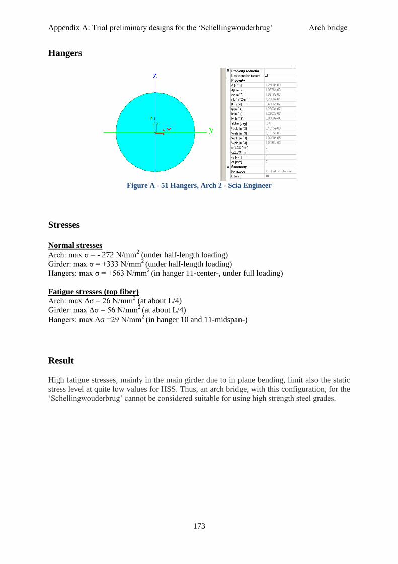
Appendix A: Trial preliminary designs for the ‘Schellingwouderbrug’ Arch bridge
173
Hangers
Figure A - 51 Hangers, Arch 2 - Scia Engineer
Stresses
Normal stresses
Arch: max σ = - 272 N/mm2 (under half-length loading)
Girder: max σ = +333 N/mm2
(under half-length loading)
Hangers: max σ = +563 N/mm2
(in hanger 11-center-, under full loading)
Fatigue stresses (top fiber)
Arch: max Δσ = 26 N/mm2 (at about L/4)
Girder: max Δσ = 56 N/mm2
(at about L/4)
Hangers: max Δσ =29 N/mm2
(in hanger 10 and 11-midspan-)
Result
High fatigue stresses, mainly in the main girder due to in plane bending, limit also the static
stress level at quite low values for HSS. Thus, an arch bridge, with this configuration, for the
‘Schellingwouderbrug’ cannot be considered suitable for using high strength steel grades.
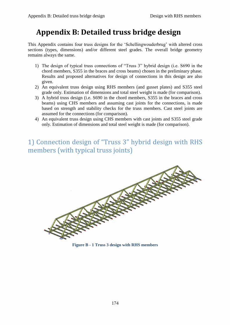
Appendix B: Detailed truss bridge design Design with RHS members
174
Appendix B: Detailed truss bridge design
This Appendix contains four truss designs for the ‘Schellingwouderbrug’ with altered cross
sections (types, dimensions) and/or different steel grades. The overall bridge geometry
remains always the same.
1) The design of typical truss connections of “Truss 3” hybrid design (i.e. S690 in the
chord members, S355 in the braces and cross beams) chosen in the preliminary phase.
Results and proposed alternatives for design of connections in this design are also
given.
2) An equivalent truss design using RHS members (and gusset plates) and S355 steel
grade only. Estimation of dimensions and total steel weight is made (for comparison).
3) A hybrid truss design (i.e. S690 in the chord members, S355 in the braces and cross
beams) using CHS members and assuming cast joints for the connections, is made
based on strength and stability checks for the truss members. Cast steel joints are
assumed for the connections (for comparison).
4) An equivalent truss design using CHS members with cast joints and S355 steel grade
only. Estimation of dimensions and total steel weight is made (for comparison).
1) Connection design of “Truss 3” hybrid design with RHS members (with typical truss joints)
Figure B - 1 Truss 3 design with RHS members
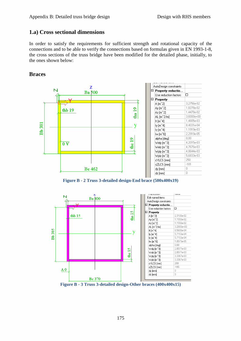
Appendix B: Detailed truss bridge design Design with RHS members
175
1.a) Cross sectional dimensions
In order to satisfy the requirements for sufficient strength and rotational capacity of the
connections and to be able to verify the connections based on formulas given in EN 1993-1-8,
the cross sections of the truss bridge have been modified for the detailed phase, initially, to
the ones shown below:
Braces
Figure B - 2 Truss 3-detailed design-End brace (500x400x19)
Figure B - 3 Truss 3-detailed design-Other braces (400x400x15)

Appendix B: Detailed truss bridge design Design with RHS members
176
Top chord
Figure B - 4 Truss 3-detailed design-Top chord (500x550x30)
Bottom chord
Figure B - 5 Truss 3-detailed design-Bottom chord (50x550x30)
Table B - 1 Cross sectional dimensions for the truss members in preliminary and detailed phase
Member Preliminary phase Detailed phase
Bottom chord 700x700 tw= 15,tf=20 500x550x30
Top chord 650x650x20 500x550x30
End brace 450x400x15 500x400x19
Rest braces 450x400x15 400x400x15

Appendix B: Detailed truss bridge design Design with RHS members
177
From Table B-1 it can be seen that the cross sections in the detailed phase have been
designed more compact in comparison to the preliminary phase.
That ensures that the sections have adequate plastic deformation capacity and sufficient
rotation capacity can also be achieved, thus, locally redistribution of stresses can take place.
This is particularly important as hinged connections are assumed for analysis. It also assures
that buckling of plate elements needs not to be checked as a failure mode.
1.b) Critical joints
Figure B - 6 Numbering of joints and brace members per truss plane
The most critical locations (in red circles in Figure 6) for each member have been found and
checked only, in order to simplify the design procedure.
By “critical” it is meant that, only the joints/connections at the most heavily loaded member
location (i.e. location on the bridge where each member must resist its maximum static load)
and fatigue sensitive location (i.e. location on the bridge where each member must resist its
maximum fatigue load or location with smaller fatigue load but worse fatigue detail class)
have been checked.
Joint type (Y- , K-gap-, K- overlap- joint) depends on the load transfer between the members
in the joint (Cidect design guide 3 [3]).
For the calculations below, internal (maximum) forces, moments and stresses due to loading
are taken from Scia file “Truss 3_RHS.esa” for strength verifications, and from Scia file
“Truss 3_RHS_FLM4.esa” for fatigue check.
Strength Strength (design resistance) calculations are done according to formulas for RHS members in
EN 1993-1-8 (design of connections). In each case, the minimum design axial resistance is
considered as the joint resistance. As high strength steel is used (S690) a reduction factor 0.8
is applied on all the design resistances independent of the failure mode [EN 1993-1-12].
Fatigue For fatigue verification, use of nominal values and fatigue details included in table 8.7 in EN
1993-1-9 is not possible. Therefore, the hot spot stress is calculated by calculating the SCFs
for each joint at different locations (toe, heel, crown etc.). Formulas for calculating the SCFs
are found in Cidect design guide 8 [5]. Analytical calculations can be found in the excel file
“RHS_ fatigue calculations SCFs.xlsx”. Below the procedure followed for fatigue is given:
Procedure for fatigue with the hot spot stress method
(See also Figure 7 for tables and graphs used in Cidect design guide 8 [5])
1. Using Scia engineer FLM4 is applied as movable load on the bridge.
Appendix B: Detailed truss bridge design Design with RHS members
178
2. Nominal ranges (forces (ΔN) and bending moments (ΔM)) are collected for each member at
each critical joint, caused by each vehicle separately.
3. Nominal stress ranges (Δσnom) are calculated from these values.
4. Stress concentrations factors (SCFs) are then calculated, separately for axial forces and
bending moments, for each critical joint at different joint locations. Relevant analytical
formulas and/or graphs are found in Cidect design guide 8, Appendix E (i.e. Table E.1 for
RHS Y-joints, Table E.2 for RHS K-gap joints and Table E.3 for RHS K-overlap joints).
5. Hot spot stress ranges (Δσhs) are calculated. Relevant formulas are found again in Cidect
design guide 8. General formula is: Δσhs = SCF*Δσnom.
6. Design fatigue life is chosen. For bridges, customary, is 100 years.
7. Traffic category for the specific bridge is chosen from table 4.5 in EN 1991-2 to be 0.5*106
cycles per year per slow lane.
8. Total number of cycles is calculated 100*(0.5*106).
9. Traffic type is chosen as medium distance (column 5) from table 4.7 in EN 1993-1-9.
10. The number of cycles per vehicle (ni) in FLM4 is calculated: lorry percentage (previous
step)* total number of cycles (from step 8).
11. Relevant hot spot S-N curve is chosen. In this case it was not clear what the most suitable S-
N curve is. This is because in Cidect 8 hot spot S-N curves cover plate thicknesses up to t=
16 mm for RHS members. In our case the design has maximum thickness 30 mm.
Therefore it was decided to use the hot spot S-N curve for CHS with t= 32 mm from table 3.2
in Cidect 8 (Figure 7), in order to get a feeling on the behavior of these connections under
fatigue loading.
It must always kept in mind however, that in Eurocode RHS truss joints are classified in a
lower fatigue class than the equivalent joints with CHS members.
12. Available fatigue life (Nf) is then calculated based on formulas in table 3.1 for t= 30 mm but
also for t = 32 mm (according to formulas in table 3.1 in Figure 7). This is done to examine
the effect of plate thickness in the formulas for the allowable number of cycles. However the
results are the same for both plate thicknesses due to the very small difference.
13. Finally Miner’s rule for total damage calculation is applied. Must D= Σ (ni/Nf, i) ≤1.
Note: In each joint the RHS member with higher fatigue stresses is checked in order to
estimate the behavior of the connection under fatigue loading. In practice though all members
and all different locations in each connection should be checked separately for fatigue.

Appendix B: Detailed truss bridge design Design with RHS members
179
Figure B - 7 Tables 3.1 and 3.2 and S-N curves for the hot spot stress method for fatigue
verifications in Cidect design guide 8.
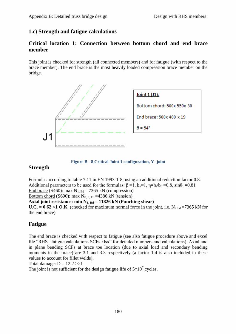
Appendix B: Detailed truss bridge design Design with RHS members
180
1.c) Strength and fatigue calculations
Critical location 1: Connection between bottom chord and end brace
member
This joint is checked for strength (all connected members) and for fatigue (with respect to the
brace member). The end brace is the most heavily loaded compression brace member on the
bridge.
Figure B - 8 Critical Joint 1 configuration, Y- joint
Strength
Formulas according to table 7.11 in EN 1993-1-8, using an additional reduction factor 0.8.
Additional parameters to be used for the formulas: β =1, kn=1, η=hi/b0 =0.8, sinθ1 =0.81
End brace (S460): max N1, Ed = 7365 kN (compression)
Bottom chord (S690): max N0, b, Ed =4386 kN (tension)
Axial joint resistance: min N1, Rd = 11826 kN (Punching shear)
U.C. = 0.62 <1 O.K. (checked for maximum normal force in the joint, i.e. Ni, Ed =7365 kN for
the end brace)
Fatigue
The end brace is checked with respect to fatigue (see also fatigue procedure above and excel
file “RHS_ fatigue calculations SCFs.xlsx” for detailed numbers and calculations). Axial and
in plane bending SCFs at brace toe location (due to axial load and secondary bending
moments in the brace) are 3.1 and 3.3 respectively (a factor 1.4 is also included in these
values to account for fillet welds).
Total damage: D = 12.2 >>1
The joint is not sufficient for the design fatigue life of 5*107 cycles.

Appendix B: Detailed truss bridge design Design with RHS members
181
Critical location 2: Connection between top chord, end brace and brace 2
members
This joint is checked for strength (all members) and for fatigue (with respect to the end brace
member). Brace 2 is the most heavily loaded tension brace member.
Figure B - 9 Critical joint 2 configuration, K- gap joint
Strength
Formulas according to table 7.12 in EN 1993-1-8, using an additional reduction factor 0.8.
Additional parameters: β = 0.85, γ =8.3, kn = 1, sinθ1 = 0.81, sinθ2 = 0.80
Also, for chord shear failure mode:
VEd = 185 kN
Vpl, Rd = (Av0*(fy0/ √3))/γM0 = 11951 kN
Av0 =A0 – 2*hw0*tw0 = 30000 mm2
A0 = 59400 mm2
End brace (S460): max N1, Ed = 7365 kN (compression)
Axial resistance: min N1, Rd = 12054 kN (Brace failure)
Brace 2 (S460): max N2, Ed = 7585 kN (tension)
Axial resistance: min N2, Rd = 8501 kN (Brace failure)
Top chord (S690): max N0, t, Ed = 8932 kN (compression)
Axial resistance: min N0, t, Rd =29630 kN (Chord shear)
Axial joint resistance: min N2, Rd = 8501 kN (Brace failure)
U.C. = 0.89< 1 O.K., for brace 2
Fatigue
The end brace is checked again with respect to fatigue (see also fatigue procedure above and
excel file “RHS_ fatigue calculations SCFs.xlsx” for detailed numbers and calculations).
Maximum axial and in plane bending SCFs (due to axial load and secondary bending
moments in the brace) in this case are 6.0 and 0.0 (negligible) respectively.
Total damage: D = 2.4 >1
The joint is not sufficient for the design fatigue life of 5*107 cycles.
Joint 2 (J2):
Top chord: 500x 550x 30
End brace: 500x 400x 19
Brace 2: 400x 400x 15
Gap g= 70 mm
Eccentricity e= + 108 mm
θ1= 54°
θ2= 53°
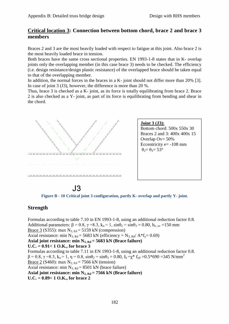
Appendix B: Detailed truss bridge design Design with RHS members
182
Critical location 3: Connection between bottom chord, brace 2 and brace 3
members
Braces 2 and 3 are the most heavily loaded with respect to fatigue at this joint. Also brace 2 is
the most heavily loaded brace in tension.
Both braces have the same cross sectional properties. EN 1993-1-8 states that in K- overlap
joints only the overlapping member (in this case brace 3) needs to be checked. The efficiency
(i.e. design resistance/design plastic resistance) of the overlapped brace should be taken equal
to that of the overlapping member.
In addition, the normal forces in the braces in a K- joint should not differ more than 20% [3].
In case of joint 3 (J3), however, the difference is more than 20 %.
Thus, brace 3 is checked as a K- joint, as its force is totally equilibrating from brace 2. Brace
2 is also checked as a Y- joint, as part of its force is equilibrating from bending and shear in
the chord.
Figure B - 10 Critical joint 3 configuration, partly K- overlap and partly Y- joint.
Strength
Formulas according to table 7.10 in EN 1993-1-8, using an additional reduction factor 0.8.
Additional parameters: β = 0.8, γ =8.3, kn = 1, sinθ2 = sinθ3 = 0.80, be, ov =150 mm
Brace 3 (S355): max N3, Ed = 5159 kN (compression)
Axial resistance: min N3, Rd = 5683 kN (efficiency = N3, Rd/ A*fy= 0.69)
Axial joint resistance: min N3, Rd = 5683 kN (Brace failure)
U.C. = 0.91< 1 O.K., for brace 3
Formulas according to table 7.11 in EN 1993-1-8, using an additional reduction factor 0.8.
β = 0.8, γ =8.3, kn = 1, η = 0.8, sinθ2 = sinθ3 = 0.80, fb =χ* fy0 =0.5*690 =345 N/mm2
Brace 2 (S460): max N2, Ed = 7566 kN (tension)
Axial resistance: min N3, Rd = 8501 kN (brace failure)
Axial joint resistance: min N2, Rd = 7566 kN (Brace failure)
U.C. = 0.89< 1 O.K., for brace 2
Joint 3 (J3):
Bottom chord: 500x 550x 30
Braces 2 and 3: 400x 400x 15
Overlap Ov= 50%
Eccentricity e= -108 mm
θ2= θ3= 53°

Appendix B: Detailed truss bridge design Design with RHS members
183
Fatigue
Brace 3 is checked here with respect to fatigue as it showed higher fatigue stresses at this
location (see also fatigue procedure above and excel file “RHS_ fatigue calculations
SCFs.xlsx” for detailed numbers and calculations). Axial and in plane bending SCFs at brace
toe location (due to axial load and secondary bending moments in the brace) are 7.8 and 0.0
(negligible) respectively.
Total damage: D = 15 >>1
The joint is not sufficient for the design fatigue life of 5*107 cycles.
Critical location 4: Connection between top chord, brace 9 and brace 10
members
Here the top chord has its maximum static internal forces but also its fatigue stresses. Both
braces have the same cross sectional properties thus the same resistance. Thus, only capacity
with respect to the loading in brace 9 (higher load in comparison to brace 10), needs to be
checked.
Figure B - 11 Critical joint 10 configuration, K- gap joint
Strength
Formulas according to table 7.12 in EN 1993-1-8, using an additional reduction factor 0.8.
Additional parameters: β = 0.8, γ =8.3, kn = 1, sinθ9 = sinθ10 = 0.80
Also, for chord shear failure mode:
VEd = 67 kN
Vpl, Rd = (Av0*(fy0/ √3))/γM0 = 11951 kN
Av0 =A0 – 2*hw0*tw0 = 30000 mm2
A0 = 59400 mm2
Brace 9 (S355): max N9, Ed = 1337 kN (compression)
Axial resistance: min N9, Rd = 6561 kN (Brace failure)
Joint 10 (J10):
Top chord: 500x 550x 30
Braces 9 and 10: 400x 400x 15
Gap g= 75 mm
Eccentricity e= +108 mm
θ9= θ10= 53°

Appendix B: Detailed truss bridge design Design with RHS members
184
Top chord (S690): max N0, t, Ed =24427 kN (compression)
Axial resistance: min N0, t, Rd = 32755 kN
Axial joint resistance: min N9, Rd = 6561 kN (Brace failure)
U.C. =0.20 <1 O.K., for brace 9
Fatigue
The top chord member is checked with respect to fatigue (see also fatigue procedure above
and excel file “RHS_ fatigue calculations SCFs.xlsx” for detailed numbers and calculations).
Maximum axial and in plane bending SCFs (due to axial load and in plane bending moments
in the chord) are 3.0 and 2.7 respectively.
Total damage: D = 0.04 <1
The joint is sufficient for the design fatigue life of 5*107cycles.
Critical location 5: Connection between bottom chord, brace 10 and brace
11 members
This joint is located almost at the middle of the bridge where the bottom chord suffers the
highest internal forces due to traffic loading. The braces are both in tension under very small
axial forces. Due to the fact that both braces are in tension the joint cannot be treated as a K-
overlap joint but as two separate Y- joints. Both braces have the same cross sectional
properties thus the same resistance. Thus, only capacity with respect to the loading in brace
10 (higher load in comparison to brace 11), needs to be checked.
Figure B - 12 Critical joint 11 configuration, as two separate Y-joints
Strength
Formulas according to table 7.11 in EN 1993-1-8, using an additional reduction factor 0.8.
Additional parameters β = 0.8, γ =8.3, kn = 1, η = 0.8, sinθ10 = sinθ11 = 0.80, fb = fy0 =690
N/mm2
Brace 10 (S355): max N10, Ed = 1190 kN (tension)
Joint 11 (J11):
Bottom chord: 500x 550x 30
Braces 10 and 11: 400x 400x 15
θ10= θ11= 53°
Appendix B: Detailed truss bridge design Design with RHS members
185
Axial resistance: min N10, Rd =6561 kN (Brace failure)
Axial joint resistance: min N10, Rd =6561 kN (Brace failure)
U.C. = 0.18 <1 O.K. , for brace 10
Fatigue
The bottom chord member is checked with respect to fatigue (see also fatigue procedure
above and excel file “RHS_ fatigue calculations SCFs.xlsx” for detailed numbers and
calculations). Maximum axial and in plane bending SCFs (due to axial load and in plane
bending moments in the chord) are 3.0 and 2.7 respectively.
Total damage: D = 2 >1
The joint is not sufficient for the design fatigue life of 5*107 cycles.
Results
It is clear that fatigue for the ‘Schellingwouderbrug’ is not satisfied with regular joints types.
Thus, alternative solutions for connections need to be made in order to improve fatigue
details and enhance fatigue resistance for the bridge.
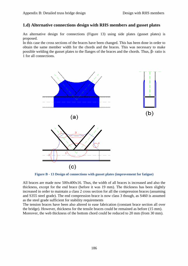
Appendix B: Detailed truss bridge design Design with RHS members
186
1.d) Alternative connections design with RHS members and gusset plates
An alternative design for connections (Figure 13) using side plates (gusset plates) is
proposed.
In this case the cross sections of the braces have been changed. This has been done in order to
obtain the same member width for the chords and the braces. This was necessary to make
possible welding the gusset plates to the flanges of the braces and the chords. Thus, β- ratio is
1 for all connections.
Figure B - 13 Design of connections with gusset plates (improvement for fatigue)
All braces are made now 500x400x16. Thus, the width of all braces is increased and also the
thickness, except for the end brace (before it was 19 mm). The thickness has been slightly
increased in order to maintain a class 2 cross section for all the compression braces (assuming
and S355 steel grade). The end compression brace is now class 3 though, as S460 is assumed
as the steel grade sufficient for stability requirements
The tension braces have been also altered to ease fabrication (constant brace section all over
the bridge). However, thickness for the tensile braces could be remained as before (15 mm).
Moreover, the web thickness of the bottom chord could be reduced to 20 mm (from 30 mm).

Appendix B: Detailed truss bridge design Design with RHS members
187
Top chord
Figure B - 14 Top chord- Design with gusset plates, U.C. =0.95
Table B - 1 In plane buckling resistance of top chord in RHS hybrid design with gusset plates
Top Chord
Area A (mm
2) 59400
Length Ly (mm) 10500
Buckling coefficient Ky 0.9
Buckling length ly (mm) 9450
Moment of Inertia Iy (mm4) 2.62E+09
Radius of gyration iy (mm) 210
Slenderness λy 45
Rel. slenderness λE 55
Buckling curve b
Imperfection factor α 0.34
Strength fyd (N/mm2) 690
E-modulus E (N/mm2) 210000
Relative slenderness λy,rel 0.82
Phi factor Φ 0.94
Buckling factor χy 0.71
Buckling strength fb,rd (N/mm2) 491

Appendix B: Detailed truss bridge design Design with RHS members
188
Bottom chord
Figure B - 15 Bottom chord- Design with gusset plates, U.C. = 0.88
All braces
Figure B - 16 All braces-Design with gusset plates, U.C = 0.89 (end brace)
Table B - 2 In plane buckling resistance of end brace in RHS hybrid design with gusset plates
End brace
Area A (mm
2) 27776
Length Ly (mm) 8750
Buckling coefficient Ky 1
Buckling length ly (mm) 8750
Moment of Inertia Iy (mm4) 7.23E+08
Radius of gyration iy (mm) 161.34

Appendix B: Detailed truss bridge design Design with RHS members
189
Table B - 3 In plane buckling resistance of rest compression braces in RHS hybrid design with
gusset plates, U.C. = 0.86 (brace 3)
Generally, the cross sections of the braces are generally conservative with respect to their
loading and thus, the stresses they need to resist are in many cases quite low (especially for
the braces close to midspan, U.C.= 0.2). In all cases the maximum steel grade does not
exceed S460 (only for the end braces to satisfy stability check).
Further design and member optimization (e.g. decreasing the cross sections for a number of
braces or decreasing the length of the braces by decreasing the field length or the bridge
height etc.) could be proven more economic. However, this procedure is time consuming. In
addition, repetition and thus simplicity of fabrication is considered to be more cost effective.
Slenderness λy 54
Rel. slenderness λE 67
Buckling curve b
Imperfection factor α 0.34
Strength fyd (N/mm2) 460
E-modulus E (N/mm2) 210000
Relative slenderness λy,rel 0.81
Phi factor Φ 0.93
Buckling factor χy 0.72
Buckling strength fb,rd (N/mm2) 331
Rest compression braces
Area A (mm
2) 27776
Length Ly (mm) 8750
Buckling coefficient Ky 1
Buckling length ly (mm) 8750
Moment of Inertia Iy (mm4) 7.23E+08
Radius of gyration iy (mm) 161.34
Slenderness λy 54
Rel. slenderness λE 76
Buckling curve b
Imperfection factor α 0.34
Strength fyd (N/mm2) 355
E-modulus E (N/mm2) 210000
Relative slenderness λy,rel 0.71
Phi factor Φ 0.84
Buckling factor χy 0.78
Buckling strength fb,rd (N/mm2) 276

Appendix B: Detailed truss bridge design Design with RHS members
190
Strength
The two side plates (gussets) are designed, conservatively, as they will carry the whole load
the members need to resist. This relies on the assumption that these plates are thick enough,
and thus stiffer, so that the load from the braces will not go through the chord face but
through the side plate to the chord wall.
The thickness of the gusset plate depends on the load it must resist. The minimum required
gusset plate thickness, if S690 steel grade is considered (fy, gplate = 690 N/mm2), for these
plates is calculated for top and bottom chord and for the most heavily loaded braces. If S355
steel grade is assumed, these values need to be doubled.
Top chord (compression): max N0, t, Ed =24427 kN, tgplate, min = (N0, t, Ed/2)/ (h0,t*fy, gplate)= 32
mm, per gusset plate
Bottom chord (tension): max N0, b, Ed =23738 kN, tgplate, min = (N0, b, Ed/2)/ (h0,b*fy, gplate)= 32
mm, per gusset plate
End brace (compression): max N1, Ed = 7365 kN, tgplate, min = (N1, Ed/2)/ (b1*fy, gplate) = 15 mm,
per gusset plate
Brace 2 (tension): max N2, Ed = 7585 kN, tgplate, min = (N2, Ed/2)/ (b2*fy, gplate) = 15 mm, per
gusset plate
Thus, assuming uniform (constant) plate thickness for the gusset plates the minimum
required plate thickness should be tg, plate, min = 32 mm.
Although not covered in this study, design of butt welds needs to ensure they have sufficient
strength (i.e. they can carry the load from the truss members to the gusset plates and vice
versa). Undermatched welds will be used in connections of the gusset plates (S690) with the
braces (mainly S355).
Fatigue
In this design the critical joints remain the same but the critical fatigue details in each joint
have changed. Now, the connections where the butt welds are located (Figure 13, locations 1
and 2) will be critical for fatigue.
This has two main advantages. Firstly, according to EN1993-1-9, these are better fatigue
details (i.e. minimum fatigue detail class is 71 if from one side butt welds is only possible,
but also higher classes are possible, e.g., class 80 or 90 if both sides can be welded) and are
also applicable for HSS. However, size effect for thickness > 25 mm needs to be considered.
Secondly, lower nominal stresses (thus relevant nominal S-N curves from EN 1993-1-9
according to detail fatigue class) can be used, which are located further from the joint’s
intersection point.
Procedure for fatigue with the nominal stress method (gusset plates & butt welds)
1. Using Scia engineer FLM4 is applied as movable load on the bridge.
2. Nominal ranges at butt welds locations (forces (ΔN) and bending moments (ΔM)) are
collected for each member at each critical joint, caused by each vehicle separately. Butt welds
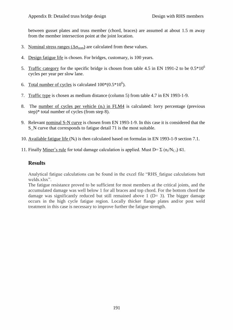
Appendix B: Detailed truss bridge design Design with RHS members
191
between gusset plates and truss member (chord, braces) are assumed at about 1.5 m away
from the member intersection point at the joint location.
3. Nominal stress ranges (Δσnom) are calculated from these values.
4. Design fatigue life is chosen. For bridges, customary, is 100 years.
5. Traffic category for the specific bridge is chosen from table 4.5 in EN 1991-2 to be 0.5*106
cycles per year per slow lane.
6. Total number of cycles is calculated 100*(0.5*106).
7. Traffic type is chosen as medium distance (column 5) from table 4.7 in EN 1993-1-9.
8. The number of cycles per vehicle (ni) in FLM4 is calculated: lorry percentage (previous
step)* total number of cycles (from step 8).
9. Relevant nominal S-N curve is chosen from EN 1993-1-9. In this case it is considered that the
S_N curve that corresponds to fatigue detail 71 is the most suitable.
10. Available fatigue life (Nf) is then calculated based on formulas in EN 1993-1-9 section 7.1.
11. Finally Miner’s rule for total damage calculation is applied. Must D= Σ (ni/Nf, i) ≤1.
Results
Analytical fatigue calculations can be found in the excel file “RHS_fatigue calculations butt
welds.xlsx”.
The fatigue resistance proved to be sufficient for most members at the critical joints, and the
accumulated damage was well below 1 for all braces and top chord. For the bottom chord the
damage was significantly reduced but still remained above 1 (D= 3). The bigger damage
occurs in the high cycle fatigue region. Locally thicker flange plates and/or post weld
treatment in this case is necessary to improve further the fatigue strength.

Appendix B: Detailed truss bridge design Design with RHS members
192
2) Truss bridge design with RHS members and only S355 steel grade
Just for design comparison on a cost basis performed in chapter 9, estimation on required
truss member dimensions is made in case that S355 steel grade is only used for the whole
bridge design. The comparison aims to show what the benefits are from a hybrid bridge
construction, under the same design concept. It is out of the scope of this study to develop the
most economical “all in S355” bridge design.
Two sub- cases are investigated: case (a) what is the minimum required plate thickness if all
the other dimensions remain the same as for the hybrid design, and case (b) what are the
minimum other cross sectional dimensions (i.e. members width, and height) required to take
the stresses if the same plate thickness is considered as for the hybrid design.
Case (a): Increase members plate thickness only
Required members thickness to satisfy strength requirements is more or less doubled for the
chord members. Unity checks are close to the case of hybrid construction. The minimum
required plate thickness to take over static stresses with S355 is shown in Figures 15-17.
Top chord (S355)
Figure B - 17 Top chord- Design with RHS members and S355 steel grade only, case (a), U.C. =
0.98
Table B - 4 In plane buckling check for top chord, “all in S355 design”, case (a)
Top Chord
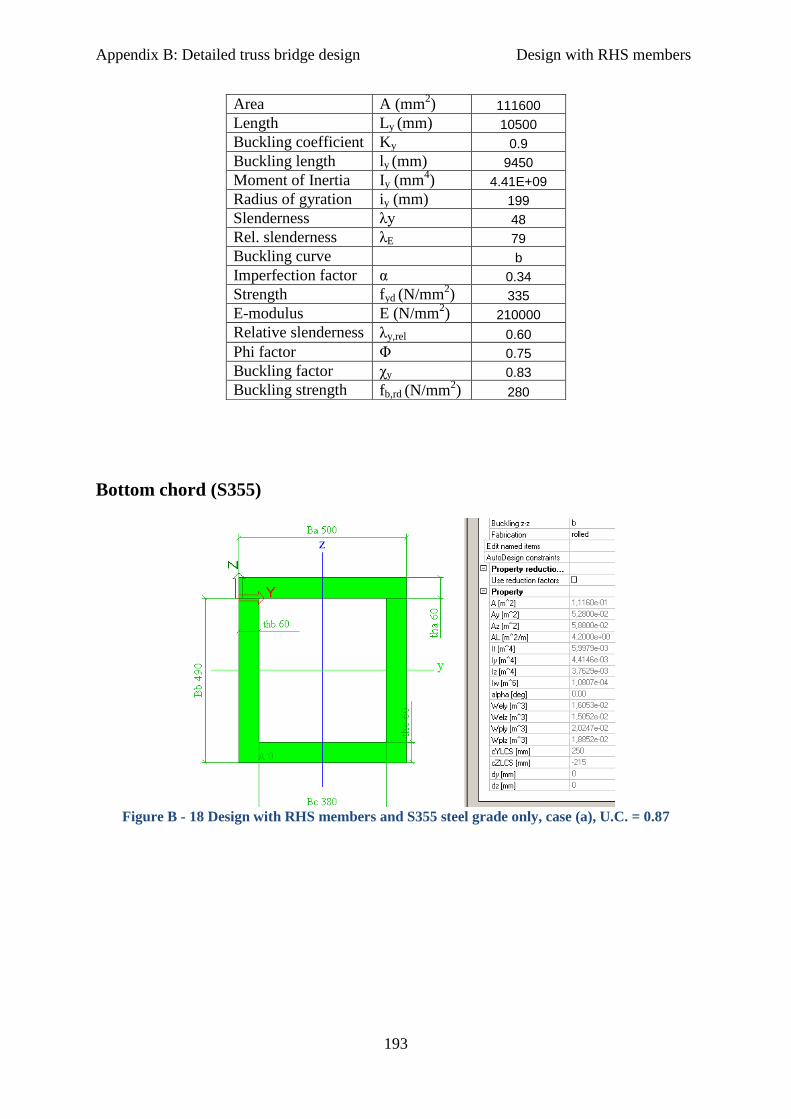
Appendix B: Detailed truss bridge design Design with RHS members
193
Bottom chord (S355)
Figure B - 18 Design with RHS members and S355 steel grade only, case (a), U.C. = 0.87
Area A (mm2) 111600
Length Ly (mm) 10500
Buckling coefficient Ky 0.9
Buckling length ly (mm) 9450
Moment of Inertia Iy (mm4) 4.41E+09
Radius of gyration iy (mm) 199
Slenderness λy 48
Rel. slenderness λE 79
Buckling curve b
Imperfection factor α 0.34
Strength fyd (N/mm2) 335
E-modulus E (N/mm2) 210000
Relative slenderness λy,rel 0.60
Phi factor Φ 0.75
Buckling factor χy 0.83
Buckling strength fb,rd (N/mm2) 280
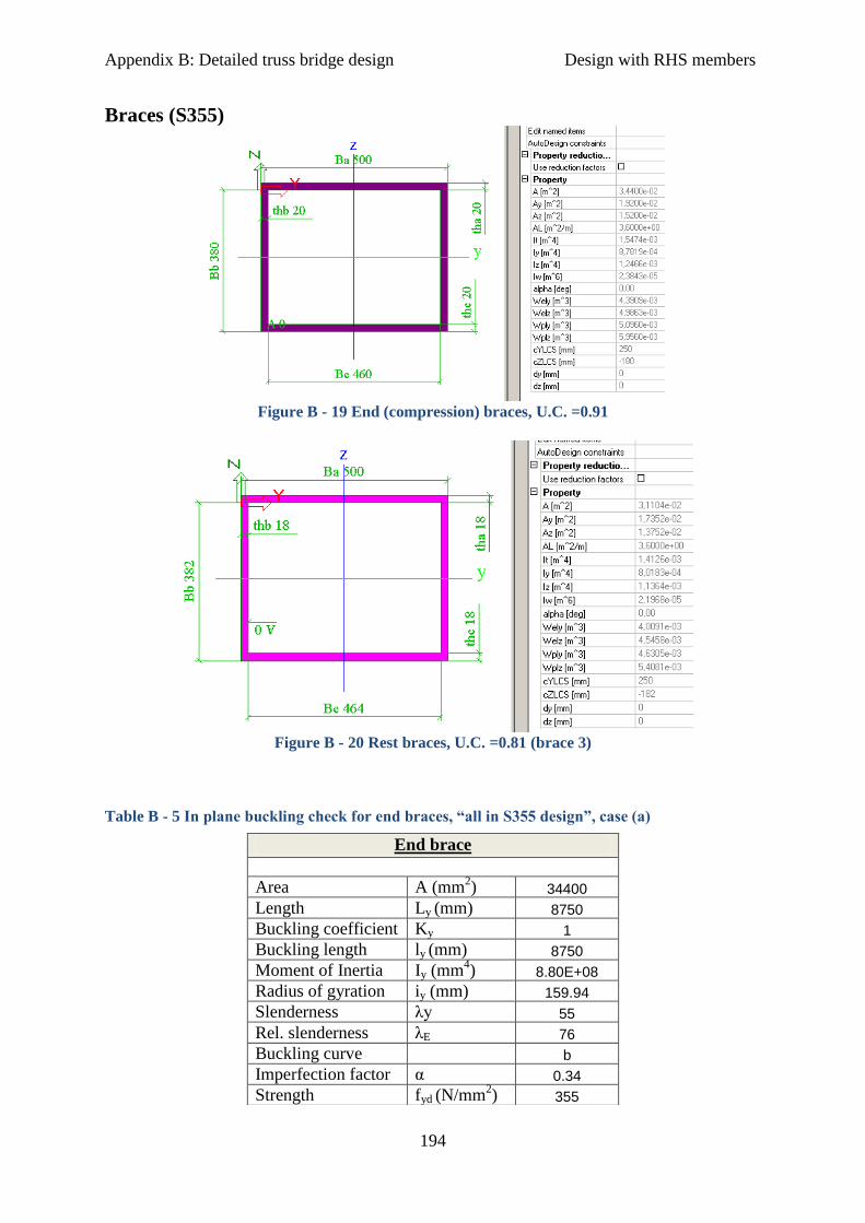
Appendix B: Detailed truss bridge design Design with RHS members
194
Braces (S355)
Figure B - 19 End (compression) braces, U.C. =0.91
Figure B - 20 Rest braces, U.C. =0.81 (brace 3)
Table B - 5 In plane buckling check for end braces, “all in S355 design”, case (a)
End brace
Area A (mm
2) 34400
Length Ly (mm) 8750
Buckling coefficient Ky 1
Buckling length ly (mm) 8750
Moment of Inertia Iy (mm4) 8.80E+08
Radius of gyration iy (mm) 159.94
Slenderness λy 55
Rel. slenderness λE 76
Buckling curve b
Imperfection factor α 0.34
Strength fyd (N/mm2) 355
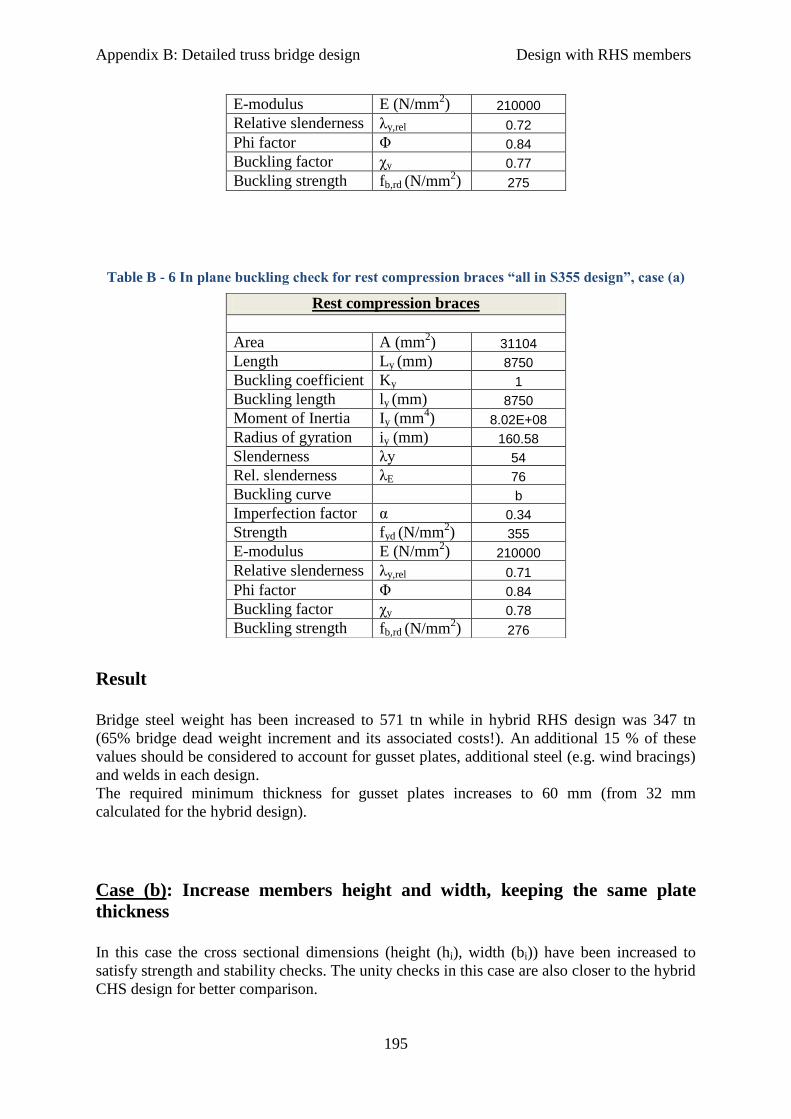
Appendix B: Detailed truss bridge design Design with RHS members
195
Table B - 6 In plane buckling check for rest compression braces “all in S355 design”, case (a)
Result
Bridge steel weight has been increased to 571 tn while in hybrid RHS design was 347 tn
(65% bridge dead weight increment and its associated costs!). An additional 15 % of these
values should be considered to account for gusset plates, additional steel (e.g. wind bracings)
and welds in each design.
The required minimum thickness for gusset plates increases to 60 mm (from 32 mm
calculated for the hybrid design).
Case (b): Increase members height and width, keeping the same plate
thickness
In this case the cross sectional dimensions (height (hi), width (bi)) have been increased to
satisfy strength and stability checks. The unity checks in this case are also closer to the hybrid
CHS design for better comparison.
E-modulus E (N/mm2) 210000
Relative slenderness λy,rel 0.72
Phi factor Φ 0.84
Buckling factor χy 0.77
Buckling strength fb,rd (N/mm2) 275
Rest compression braces
Area A (mm
2) 31104
Length Ly (mm) 8750
Buckling coefficient Ky 1
Buckling length ly (mm) 8750
Moment of Inertia Iy (mm4) 8.02E+08
Radius of gyration iy (mm) 160.58
Slenderness λy 54
Rel. slenderness λE 76
Buckling curve b
Imperfection factor α 0.34
Strength fyd (N/mm2) 355
E-modulus E (N/mm2) 210000
Relative slenderness λy,rel 0.71
Phi factor Φ 0.84
Buckling factor χy 0.78
Buckling strength fb,rd (N/mm2) 276
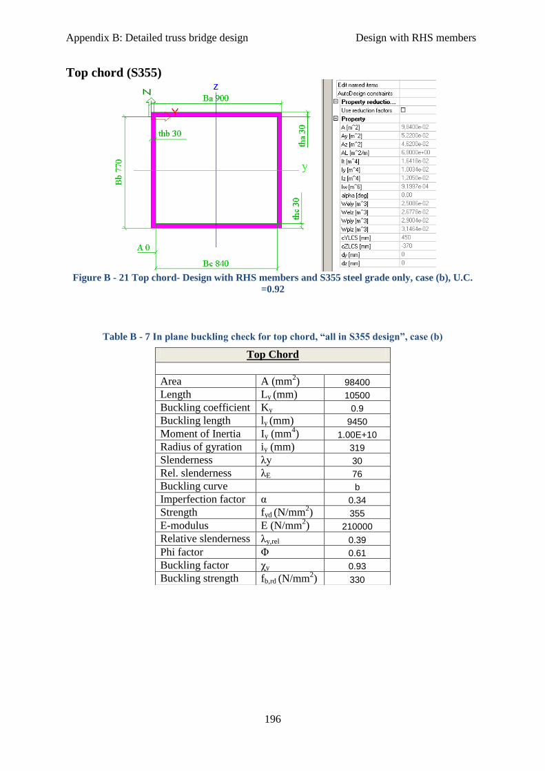
Appendix B: Detailed truss bridge design Design with RHS members
196
Top chord (S355)
Figure B - 21 Top chord- Design with RHS members and S355 steel grade only, case (b), U.C.
=0.92
Table B - 7 In plane buckling check for top chord, “all in S355 design”, case (b)
Top Chord
Area A (mm
2) 98400
Length Ly (mm) 10500
Buckling coefficient Ky 0.9
Buckling length ly (mm) 9450
Moment of Inertia Iy (mm4) 1.00E+10
Radius of gyration iy (mm) 319
Slenderness λy 30
Rel. slenderness λE 76
Buckling curve b
Imperfection factor α 0.34
Strength fyd (N/mm2) 355
E-modulus E (N/mm2) 210000
Relative slenderness λy,rel 0.39
Phi factor Φ 0.61
Buckling factor χy 0.93
Buckling strength fb,rd (N/mm2) 330

Appendix B: Detailed truss bridge design Design with RHS members
197
Bottom chord (S355)
Figure B - 22 Bottom chord- Design with RHS members and S355 steel grade only, case (b),
U.C. =0.88
Braces (S355)
Figure B - 23 End (compression) braces, U.C. =0.93
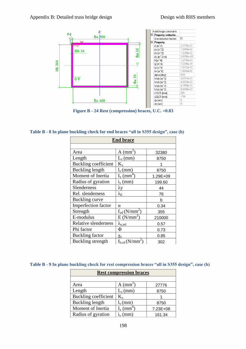
Appendix B: Detailed truss bridge design Design with RHS members
198
Figure B - 24 Rest (compression) braces, U.C. =0.83
Table B - 8 In plane buckling check for end braces “all in S355 design”, case (b)
Table B - 9 In plane buckling check for rest compression braces “all in S355 design”, case (b)
End brace
Area A (mm
2) 32380
Length Ly (mm) 8750
Buckling coefficient Ky 1
Buckling length ly (mm) 8750
Moment of Inertia Iy (mm4) 1.29E+09
Radius of gyration iy (mm) 199.60
Slenderness λy 44
Rel. slenderness λE 76
Buckling curve b
Imperfection factor α 0.34
Strength fyd (N/mm2) 355
E-modulus E (N/mm2) 210000
Relative slenderness λy,rel 0.57
Phi factor Φ 0.73
Buckling factor χy 0.85
Buckling strength fb,rd (N/mm2) 302
Rest compression braces
Area A (mm
2) 27776
Length Ly (mm) 8750
Buckling coefficient Ky 1
Buckling length ly (mm) 8750
Moment of Inertia Iy (mm4) 7.23E+08
Radius of gyration iy (mm) 161.34
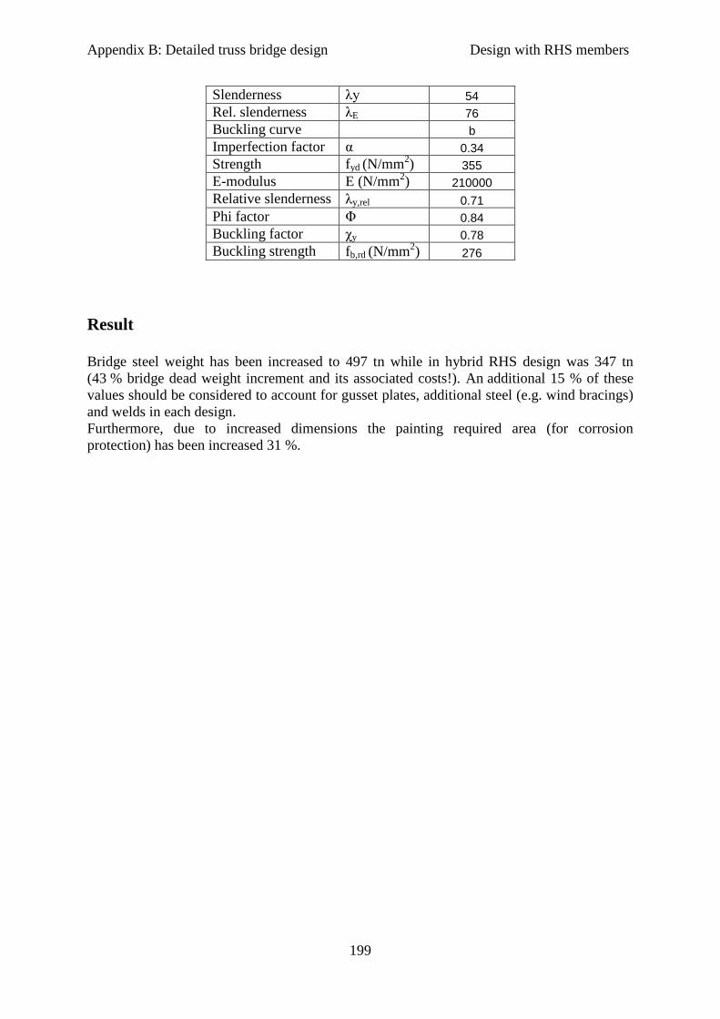
Appendix B: Detailed truss bridge design Design with RHS members
199
Result
Bridge steel weight has been increased to 497 tn while in hybrid RHS design was 347 tn
(43 % bridge dead weight increment and its associated costs!). An additional 15 % of these
values should be considered to account for gusset plates, additional steel (e.g. wind bracings)
and welds in each design.
Furthermore, due to increased dimensions the painting required area (for corrosion
protection) has been increased 31 %.
Slenderness λy 54
Rel. slenderness λE 76
Buckling curve b
Imperfection factor α 0.34
Strength fyd (N/mm2) 355
E-modulus E (N/mm2) 210000
Relative slenderness λy,rel 0.71
Phi factor Φ 0.84
Buckling factor χy 0.78
Buckling strength fb,rd (N/mm2) 276

Appendix B: detailed truss bridge design Design with CHS members
200
3) Hybrid truss bridge design with CHS members and cast joints
Figure B - 25 Truss design with CHS members
3. a) Cross sectional dimensions and calculations
For the design with CHS members standardized cross sections have been chosen, as they
were available at the sizes required for strength and stability.
To facilitate comparison, high strength steel S690 is applied in the chord members, while
S355 in the braces (S460 only in the end braces) and in the cross beams as in case of RHS
members.
Global calculations for strength (maximum static stresses are limited to the yield stress-
elastic analysis) and stability (see also excel file “Stability check.xls”) have been performed
as in case of RHS members in the preliminary phase.
Loadings are exactly the same as in all other bridge designs (see preliminary phase-
Appendix A).
The connections are assumed to be made of castings. They have not been examined in detail,
however, it is possible to choose an optimal casting for these connections using FEM
analysis. Castings for S690 steel grade (and even higher) are available.

Appendix B: detailed truss bridge design Design with CHS members
201
Strength and stability
Top chord
Figure B - 26 Top chord, standard sections (610x32), U.C. = 0.97
Table B - 10 In plane buckling strength for top chord, hybrid design with CHS members and
cast joints
Top Chord
Area A (mm
2) 58095
Length Ly (mm) 10500
Buckling coefficient Ky 0.9
Buckling length ly (mm) 9450
Moment of Inertia Iy (mm4) 2.43E+09
Radius of gyration iy (mm) 205
Slenderness λy 46
Rel. slenderness λE 55
Buckling curve b
Imperfection factor α 0.34
Strength fyd (N/mm2) 690
E-modulus E (N/mm2) 210000
Relative slenderness λy,rel 0.84
Phi factor Φ 0.96
Buckling factor χy 0.70
Buckling strength fb,rd (N/mm2) 481
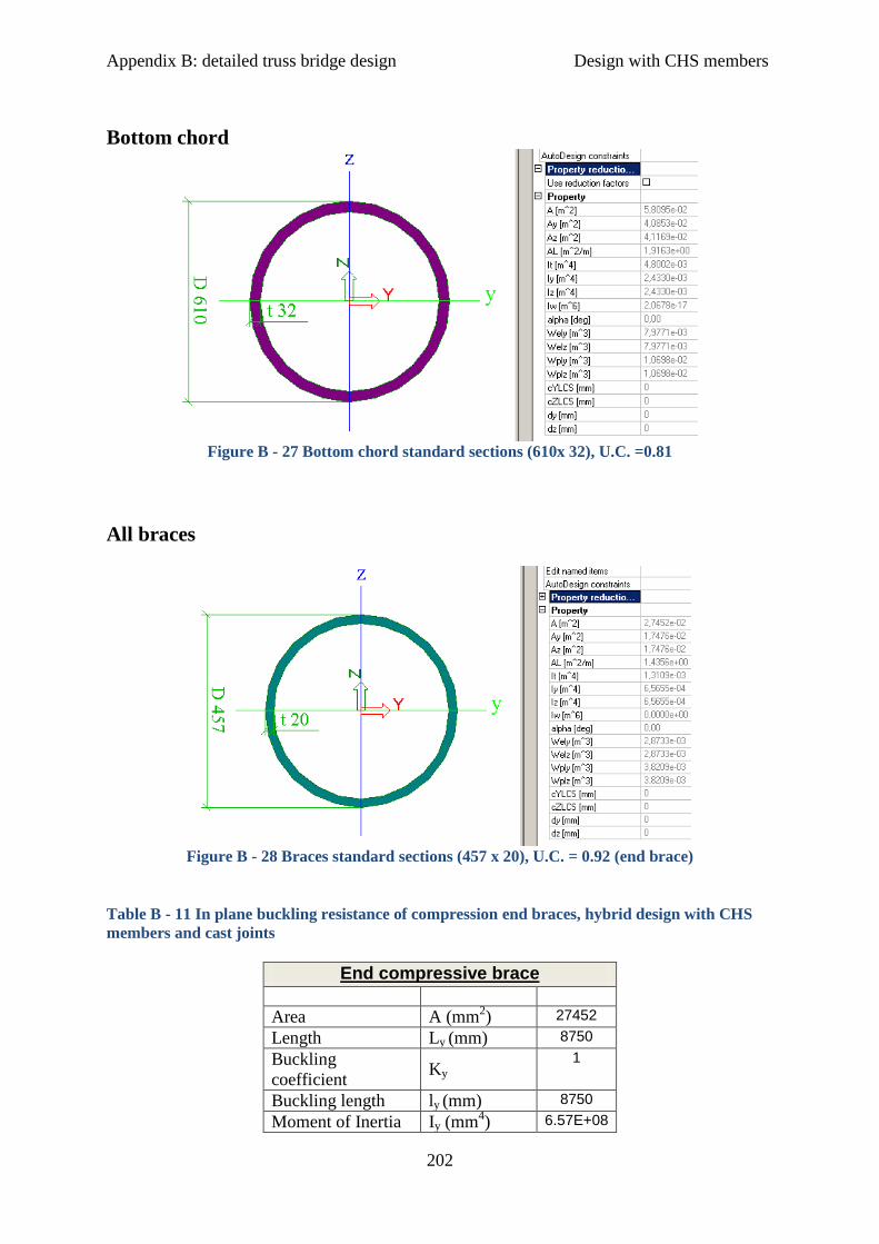
Appendix B: detailed truss bridge design Design with CHS members
202
Bottom chord
Figure B - 27 Bottom chord standard sections (610x 32), U.C. =0.81
All braces
Figure B - 28 Braces standard sections (457 x 20), U.C. = 0.92 (end brace)
Table B - 11 In plane buckling resistance of compression end braces, hybrid design with CHS
members and cast joints
End compressive brace
Area A (mm2) 27452
Length Ly (mm) 8750
Buckling
coefficient Ky
1
Buckling length ly (mm) 8750
Moment of Inertia Iy (mm4) 6.57E+08

Appendix B: detailed truss bridge design Design with CHS members
203
Radius of gyration iy (mm) 154,70
Slenderness λy 57
Rel. slenderness λE 67
Buckling curve b
Imperfection factor α 0,34
Strength fyd (N/mm2) 460
E-modulus E (N/mm2) 210000
Relative
slenderness λy,rel
0,84
Phi factor Φ 0,96
Buckling factor χy 0,70
Buckling strength fb,rd (N/mm2) 321
Table B – 12 In plane buckling resistance of rest compression braces, hybrid design with CHS
members and cast joints, U.C. = 0.85
Rest compressive brace
Area A (mm2) 27452
Length Ly (mm) 8750
Buckling
coefficient Ky
1
Buckling length ly (mm) 8750
Moment of Inertia Iy (mm4) 6.57E+08
Radius of gyration iy (mm) 154.70
Slenderness λy 57
Rel. slenderness λE 76
Buckling curve b
Imperfection factor α 0.34
Strength fyd (N/mm2) 355
E-modulus E (N/mm2) 210000
Relative
slenderness λy,rel
0.74
Phi factor Φ 0.87
Buckling factor χy 0.76
Buckling strength fb,rd (N/mm2) 270
For the tensile braces maximum static stress is + 302 N/mm2
(in brace 2). So, S355 steel
grade is sufficient, U.C. = 0.85.
Appendix B: detailed truss bridge design Design with CHS members
204
Fatigue
Critical fatigue locations are considered at the connections (butt welds) between cast steel
and circular hollow section members. Specific calculations can be found in the excel file
“CHS_ fatigue calculations butt welds.xlsx”.
Generally the results showed sufficient fatigue strength (in all joints D<1) except in case of
the bottom chord (in joint 11), where the total calculated damage was about D= 3.5>1.
Similar to the case of RHS members with gusset plates extra care is necessary for this
connection (at joint J11). Especially if post weld treatment according to IIW
recommendations is applied (in literature survey reference [63]), then fatigue stresses can be
reduced by a factor 1.5. In this case scenario the calculated fatigue damage for the bottom
chord is well below 1, also.

Appendix B: detailed truss bridge design Design with CHS members
205
4) Truss bridge design with CHS members, all in S355 steel grade
Case (a): Increase member thickness only`
Required members thickness to satisfy strength requirements is doubled for the chord
members. Unity checks are a bit higher than in case of hybrid construction which means that
even bigger thickness may be necessary. However, the minimum required plate thickness to
take over static stresses with S355 is shown in Figures 29-32.
Top chord (S355)
Figure B - 29 Top chord- Design with CHS members and S355 steel grade only, case (a), U.C.
=0.97
Table B - 3 In plane buckling resistance of top chord, “all in S355” with CHS members and cast
joints, case (a)
Top chord
Area A (mm2) 111270
Length Ly (mm) 10500
Buckling
coefficient Ky
0.9
Buckling length ly (mm) 9450
Moment of Inertia Iy (mm4) 4.18E+09
Radius of gyration iy (mm) 194
Slenderness λy 49
Rel. slenderness λE 79
Buckling curve b

Appendix B: detailed truss bridge design Design with CHS members
206
Imperfection factor α 0.34
Strength fyd (N/mm2) 335.00
E-modulus E (N/mm2) 210000
Relative
slenderness λy,rel
0.62
Phi factor Φ 0.76
Buckling factor χy 0.83
Buckling strength fb,rd (N/mm2) 277
Bottom chord (S355)
Figure B - 30 Bottom chord- Design with CHS members and S355 steel grade only, case (a),
U.C. =0.91
Braces (S355)
Figure B - 31 End braces, standard section (457x25)- Design with CHS members and S355 steel
grade only, case (a), U.C. =0.97
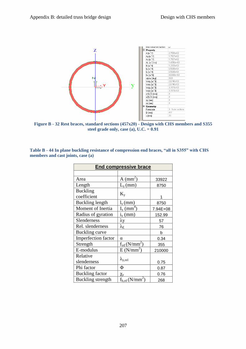
Appendix B: detailed truss bridge design Design with CHS members
207
Figure B - 32 Rest braces, standard sections (457x20) - Design with CHS members and S355
steel grade only, case (a), U.C. = 0.91
Table B - 44 In plane buckling resistance of compression end braces, “all in S355” with CHS
members and cast joints, case (a)
End compressive brace
Area A (mm2) 33922
Length Ly (mm) 8750
Buckling
coefficient Ky
1
Buckling length ly (mm) 8750
Moment of Inertia Iy (mm4) 7.94E+08
Radius of gyration iy (mm) 152.99
Slenderness λy 57
Rel. slenderness λE 76
Buckling curve b
Imperfection factor α 0.34
Strength fyd (N/mm2) 355
E-modulus E (N/mm2) 210000
Relative
slenderness λy,rel
0.75
Phi factor Φ 0.87
Buckling factor χy 0.76
Buckling strength fb,rd (N/mm2) 268

Appendix B: detailed truss bridge design Design with CHS members
208
Table B - 55 In plane buckling resistance of rest compression braces, hybrid design with CHS
members and cast joints, case (a)
Rest compressive brace
Area A (mm2) 27452
Length Ly (mm) 8750
Buckling
coefficient Ky
1
Buckling length ly (mm) 8750
Moment of Inertia Iy (mm4) 6.57E+08
Radius of gyration iy (mm) 154.70
Slenderness λy 57
Rel. slenderness λE 76
Buckling curve b
Imperfection factor α 0.34
Strength fyd (N/mm2) 355
E-modulus E (N/mm2) 210000
Relative
slenderness λy,rel
0.74
Phi factor Φ 0.87
Buckling factor χy 0.76
Buckling strength fb,rd (N/mm2) 270
Result
Bridge steel weight has been increased to 562 tn while in hybrid RHS design was 375 tn
(50% bridge dead weight increment and its associated costs!). An additional 15 % of these
values should be considered to account for cast steel, additional steel (e.g. wind bracings) and
welds in each design.

Appendix B: detailed truss bridge design Design with CHS members
209
Case (b): Increase cross sectional area keeping the same plate thickness
In this case the cross sectional dimensions (height, width) have been increased (i.e. doubled)
to satisfy strength and stability checks. The unity checks in this case are also closer to the
hybrid CHS design for better comparison.
Top chord (S355)
Figure B - 33 Top chord- Design with CHS members and S355 steel grade only, case (b), U.C.
=0.94
Table B - 66 In plane buckling resistance of top chord, “all in S355” with CHS members and
cast joints, case (b)
Top chord
Area A (mm2) 97294
Length Ly (mm) 10500
Buckling
coefficient Ky
0.9
Buckling length ly (mm) 9450
Moment of Inertia Iy (mm4) 1.14E+10
Radius of gyration iy (mm) 342
Slenderness λy 28
Rel. slenderness λE 76
Buckling curve b
Imperfection factor α 0.34
Strength fyd (N/mm2) 355
E-modulus E (N/mm2) 210000
Relative
slenderness λy,rel
0.36
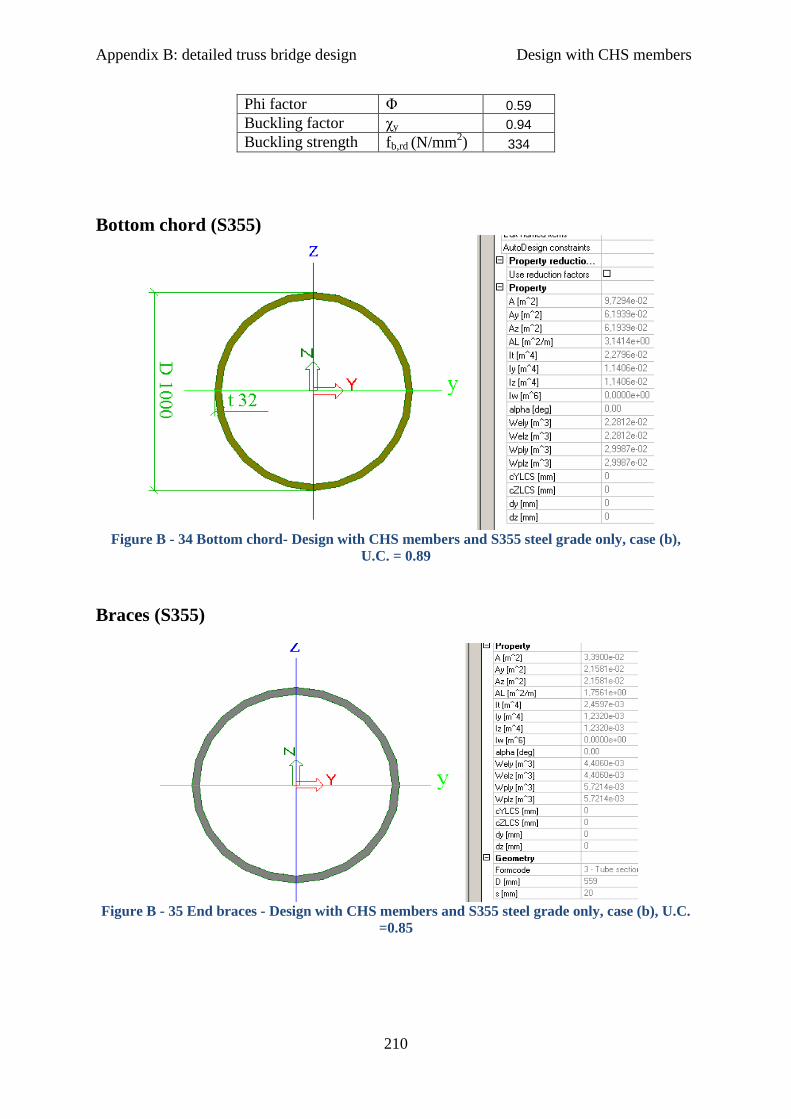
Appendix B: detailed truss bridge design Design with CHS members
210
Phi factor Φ 0.59
Buckling factor χy 0.94
Buckling strength fb,rd (N/mm2) 334
Bottom chord (S355)
Figure B - 34 Bottom chord- Design with CHS members and S355 steel grade only, case (b),
U.C. = 0.89
Braces (S355)
Figure B - 35 End braces - Design with CHS members and S355 steel grade only, case (b), U.C.
=0.85

Appendix B: detailed truss bridge design Design with CHS members
211
Figure B - 36 Rest braces - Design with CHS members and S355 steel grade only, case (b), U.C.
=0.81
Table B - 17 In plane buckling resistance of compression end braces, “all in S355” with CHS
members and cast joints, case (b)
End braces
Area A (mm2) 33900
Length Ly (mm) 8750
Buckling
coefficient Ky
1
Buckling length ly (mm) 8750
Moment of Inertia Iy (mm4) 1.23E+09
Radius of gyration iy (mm) 190.48
Slenderness λy 46
Rel. slenderness λE 76
Buckling curve b
Imperfection factor α 0.34
Strength fyd (N/mm2) 355
E-modulus E (N/mm2) 210000
Relative
slenderness λy,rel
0.60
Phi factor Φ 0.75
Buckling factor χy 0.84
Buckling strength fb,rd (N/mm2) 297
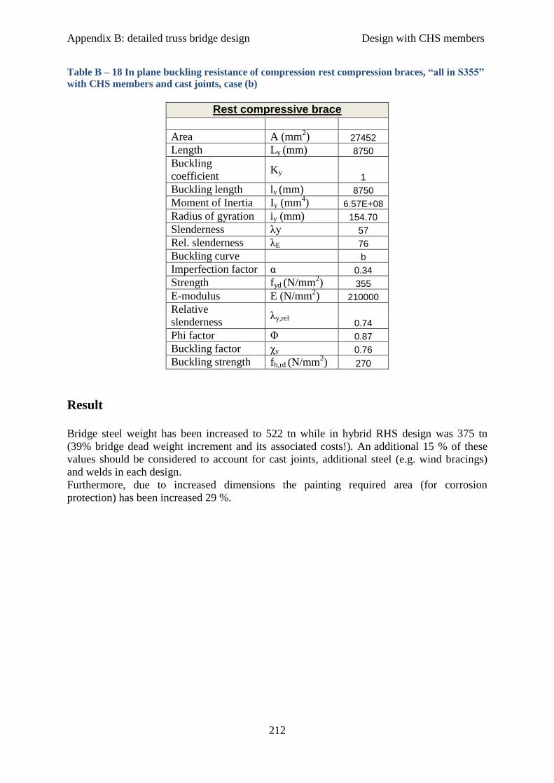
Appendix B: detailed truss bridge design Design with CHS members
212
Table B – 18 In plane buckling resistance of compression rest compression braces, “all in S355”
with CHS members and cast joints, case (b)
Rest compressive brace
Area A (mm2) 27452
Length Ly (mm) 8750
Buckling
coefficient Ky
1
Buckling length ly (mm) 8750
Moment of Inertia Iy (mm4) 6.57E+08
Radius of gyration iy (mm) 154.70
Slenderness λy 57
Rel. slenderness λE 76
Buckling curve b
Imperfection factor α 0.34
Strength fyd (N/mm2) 355
E-modulus E (N/mm2) 210000
Relative
slenderness λy,rel
0.74
Phi factor Φ 0.87
Buckling factor χy 0.76
Buckling strength fb,rd (N/mm2) 270
Result
Bridge steel weight has been increased to 522 tn while in hybrid RHS design was 375 tn
(39% bridge dead weight increment and its associated costs!). An additional 15 % of these
values should be considered to account for cast joints, additional steel (e.g. wind bracings)
and welds in each design.
Furthermore, due to increased dimensions the painting required area (for corrosion
protection) has been increased 29 %.