Embed Size (px)
Citation preview
USE OF GEOSYNTHETICS FOR FILTRATION AND DRAINAGE
Prof. G L Sivakumar BabuDepartment of Civil EngineeringIndian Institute of ScienceBangalore 560012

Retain particles of the base soil to be filteredAvoid piping
• Allow free flow of water- upstream of the filter
Avoid external clogging(With unstable soils)
- through the filterAvoid internal clogging
• Survive construction and environmental stresses• Function can be provided by either natural
aggregates or by Geotextiles
Functions of a Filter
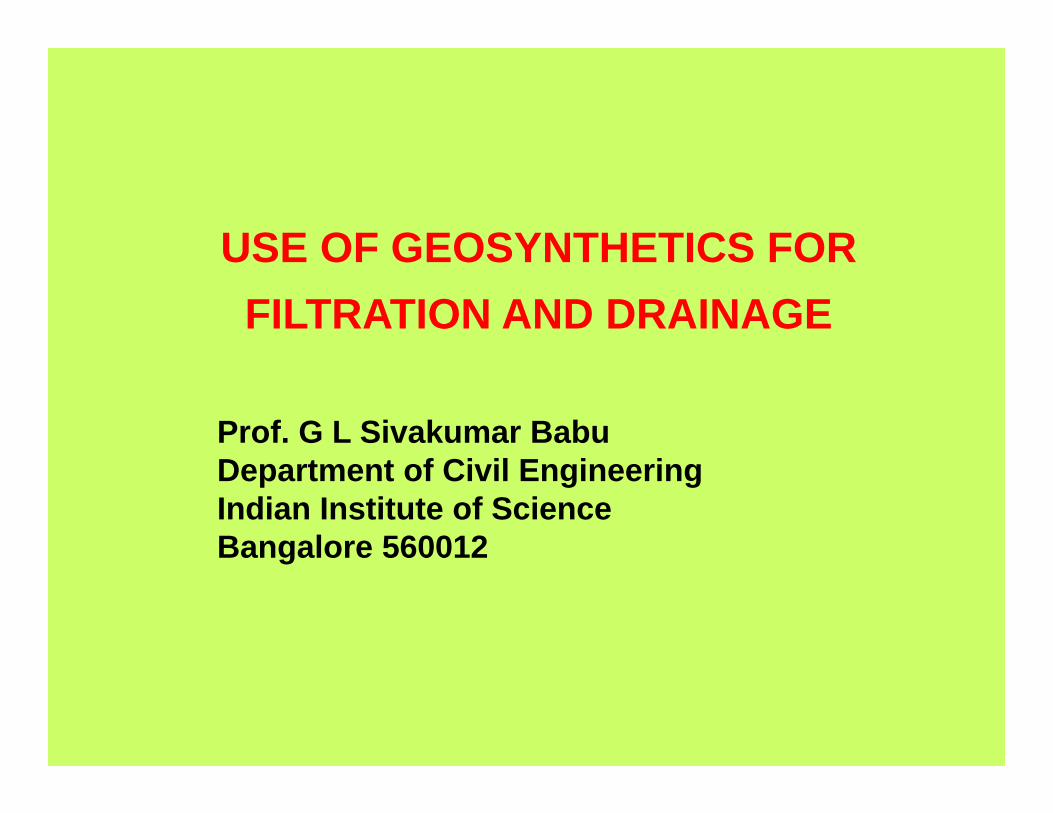
SIMILARITIES
- Thickness
- Risks of internal clogging by
2. aerobic bacterial activity (ochre clogging)3. deicing salt precipitation4. ice lens formation within the frost penetration zone
1. finer particles of the soils to be filtered
25 - 40 % 75 - 95 %- Porosity
Medium to high
Factory-controlled mass perunit area and thickness
Altered by ultraviolet rays
Variable
Low to high
- Capillary rise hcNone
None
- Tensile strength
Negligible- Compressibility
Invariable
Variable gradation as per borrow pit
Completely inertMust not be contamined bythe surrounding soil.
Compaction needed
Subject to puncture andtearing
Must be installed in intimatecontact with the soil to be filteredInstallation eased by seamingof the joints
- Transmissivity under confining stress
- Uniformity
- Durability
- Installation
- Risk of damage
DIFFERENCES
AGGREGATES GEOSYNTHETICS
High ( 150 mm) Low ( 30 mm)
Low to none ( 50 mm )hc Important ( 500 mm )hc
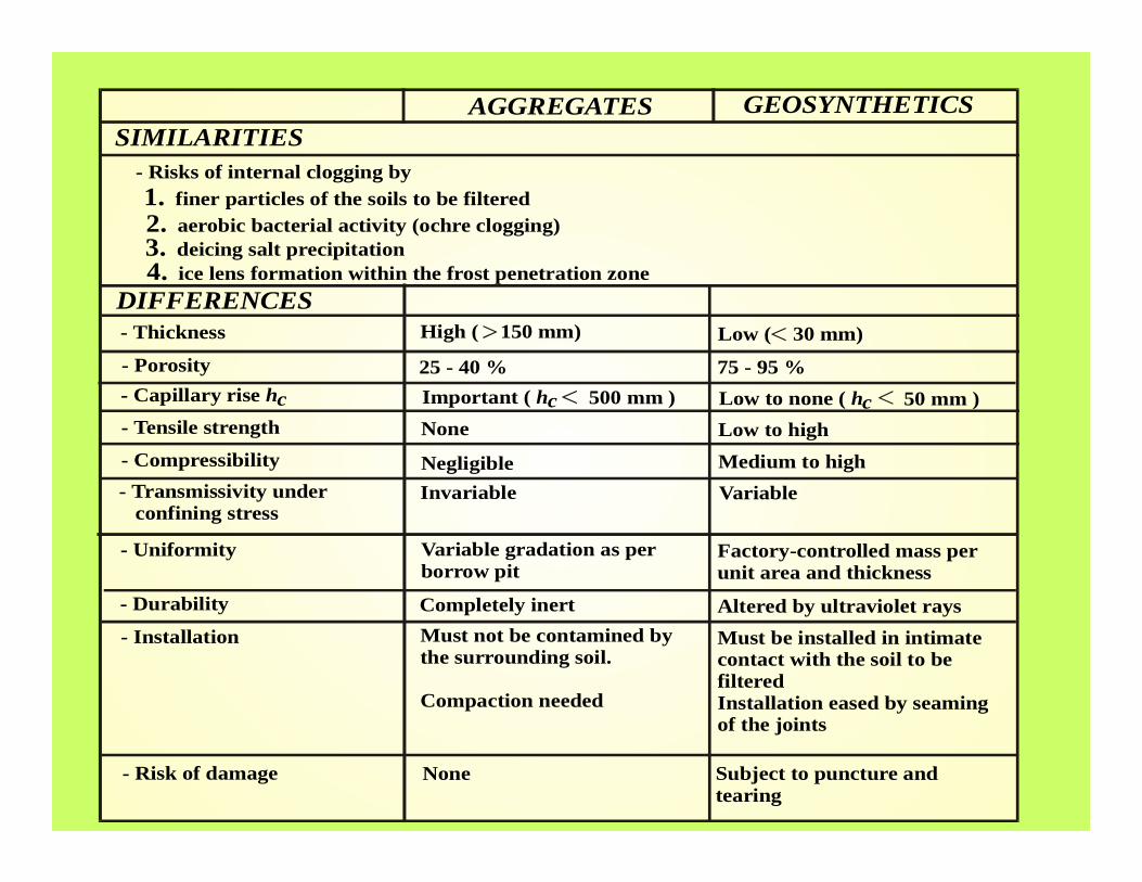
Filtration Behaviour
• Clogging: the voids of a medium are progressively filled by solid matter to the point that the passage of water is compromised
- Decrease in hydraulic conductivity
• Internal clogging
- By mineral particles- By precipitation and chemical deposition in the voids by water containing iron, de-icing salts- By biological growth encrustation in aerobic conditions

Base - Filter Interaction
internal
Interface
Piped particles Continuous paths
externalClogging particles Filaments / Fibres
tGT
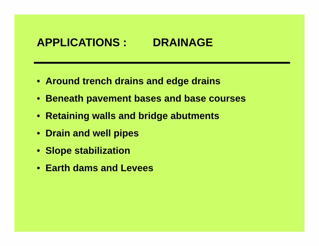
APPLICATIONS : DRAINAGE
• Around trench drains and edge drains
• Beneath pavement bases and base courses
• Retaining walls and bridge abutments
• Drain and well pipes
• Slope stabilization
• Earth dams and Levees

APPLICATIONS : EROSION CONTROL
• Protection of runoff collection
• Slope protection
• Along stream banks
• Scour protection around structures
• Construction facilities across/adjacent to water bodies
• Culverts, drop inlets, artificial stream channels
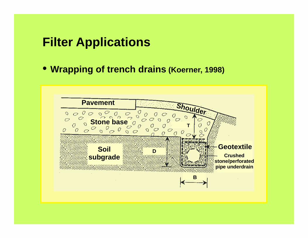
Filter Applications
• Wrapping of trench drains (Koerner, 1998)
D
B
T
Soil subgrade
Stone base
Pavement Shoulder
GeotextileCrushed
stone/perforatedpipe underdrain
1 4l
Wee phole
Geot extile
1 4l
Wee phole
Geot extile
1 4l
Wee phole
Geot extile
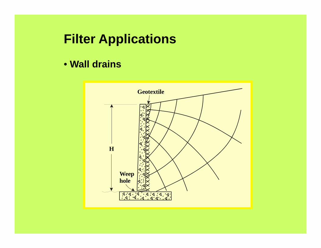
Filter Applications
• Wall drains
Weephole
Geotextile
H

Filter Applications• Erosion protection
RIVER
POND
BUILDING
GEOTEXTILE
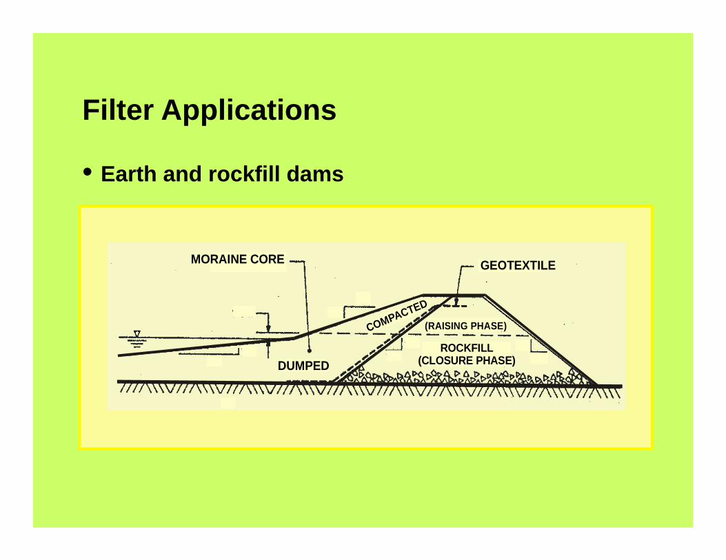
Filter Applications
• Earth and rockfill dams
MORAINE CORE GEOTEXTILE
ROCKFILL(CLOSURE PHASE)
(RAISING PHASE)COMPACTED
DUMPED

FILL(Draining) SETTLEMENT
de
CO
MPR
ESSI
BLE
SOFT
CLA
Y
DRAINING LAYER
H
Filter Applications
• Vertical consolidation drains
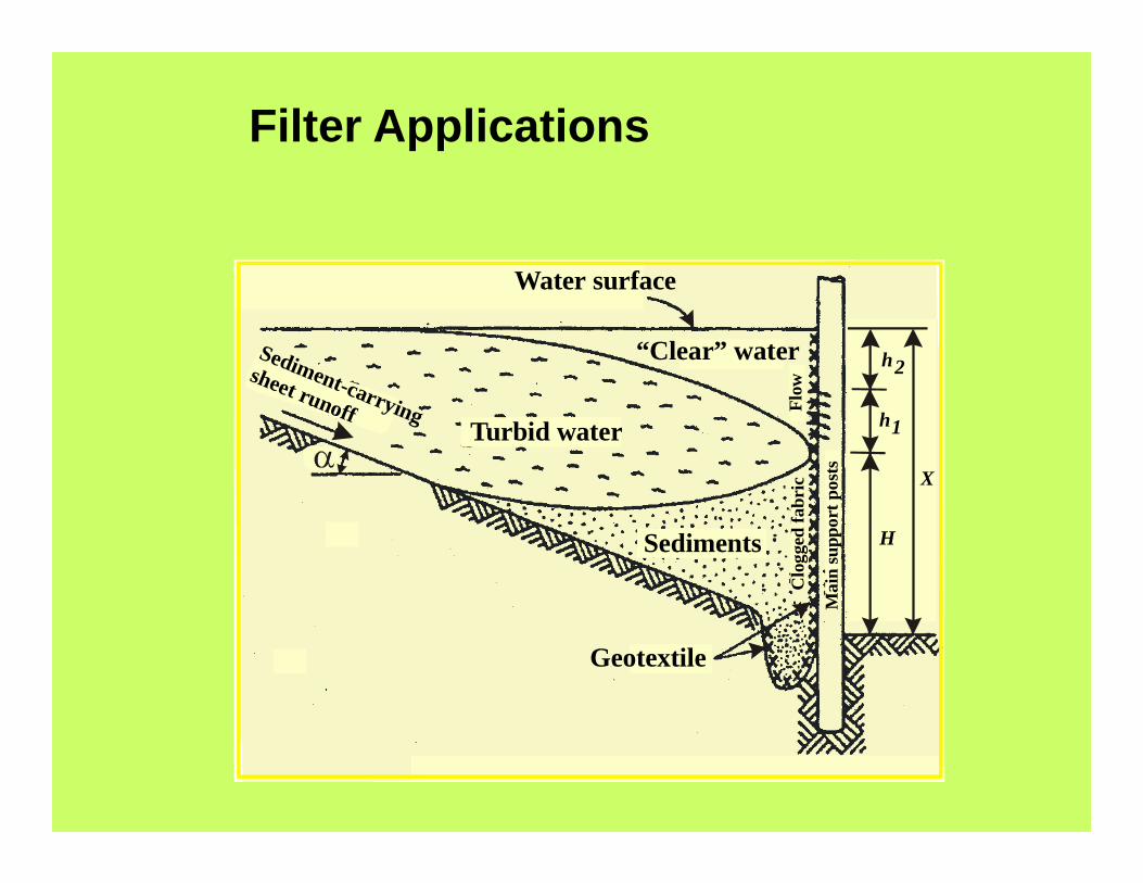
Filter Applications
Sediments
Geotextile
Sediment-carrying
sheet runoff
Water surface
“Clear” water
Turbid water
Mai
n su
ppor
t pos
ts
Clo
gged
fabr
icFl
ow
H
X
h1
h2
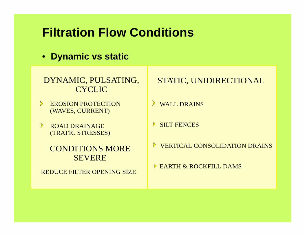
Filtration Flow Conditions
• Dynamic vs static
CONDITIONS MORE SEVERE
DYNAMIC, PULSATING,CYCLIC
STATIC, UNIDIRECTIONAL
EROSION PROTECTION (WAVES, CURRENT)
WALL DRAINS
SILT FENCES
EARTH & ROCKFILL DAMS
VERTICAL CONSOLIDATION DRAINS
ROAD DRAINAGE (TRAFIC STRESSES)
REDUCE FILTER OPENING SIZE
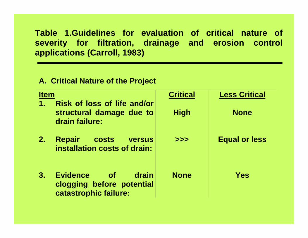
Table 1.Guidelines for evaluation of critical nature ofseverity for filtration, drainage and erosion controlapplications (Carroll, 1983)
A. Critical Nature of the Project
Item1. Risk of loss of life and/or
structural damage due todrain failure:
2. Repair costs versusinstallation costs of drain:
3. Evidence of drainclogging before potentialcatastrophic failure:
Critical
High
>>>
None
Less Critical
None
Equal or less
Yes

B. Severity of the Conditions Item
1. Soil to be drained:
2. Hydraulic
gradient: 3. Flow
conditions:
Severe
Gap-graded, pipable,
Or dispersible
High
Dynamic, cyclic, or pulsating
Less Severe
Well-graded oruniform
Low
Steady state
Guidelines (Continued)

Granular filter design criteria
a)Retention Criteria:
d 15(filter)< 4 to 5
d 85(soil)
b)Permeability Criteria:
d 15(filter)> 4 to 5
d 15(soil)

Geotextile filter requirements:
• Retention criteria
• Permeability criteria
• Anti-clogging criteria
• Serviceability criteria
• Durability criteria
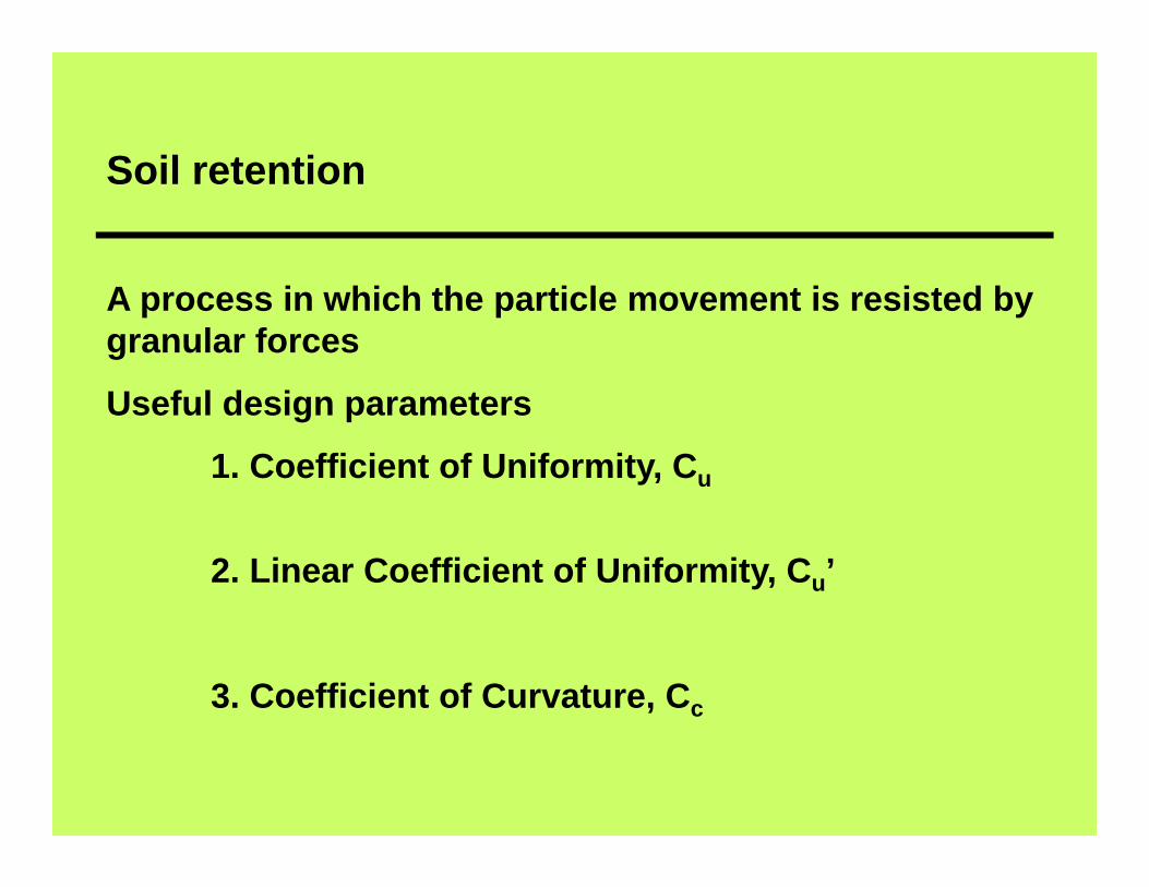
Soil retention
A process in which the particle movement is resisted by granular forces
Useful design parameters
1. Coefficient of Uniformity, Cu
2. Linear Coefficient of Uniformity, Cu’
3. Coefficient of Curvature, Cc
Design Charts
Determination of soil retention requirements such as
particle size distribution, Atterberg limits, dispersion
potential, soil density conditions indicating the effect of
confining stress, are all considered and design charts
are prepared by Giroud (1988).
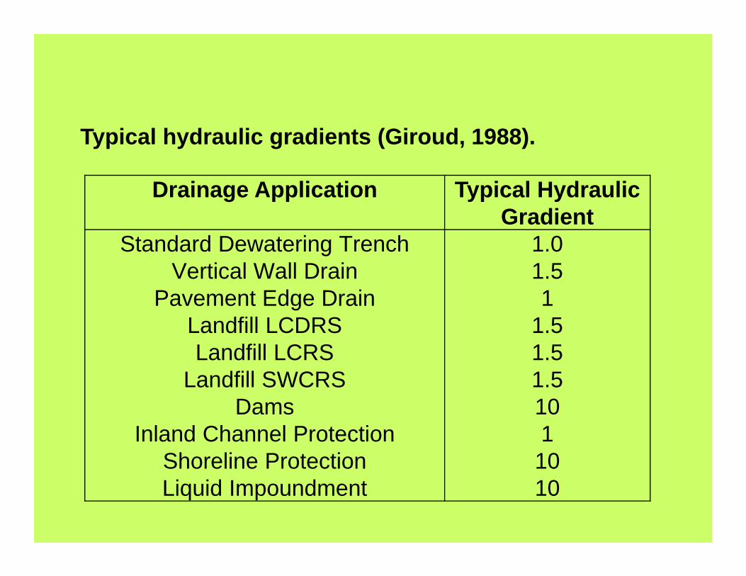
Drainage Application Typical Hydraulic Gradient
Standard Dewatering TrenchVertical Wall Drain
Pavement Edge DrainLandfill LCDRSLandfill LCRS
Landfill SWCRSDams
Inland Channel ProtectionShoreline ProtectionLiquid Impoundment
1.01.51
1.51.51.51011010
Typical hydraulic gradients (Giroud, 1988).

Soil Conditions Low Confining Pressures (TYP 50 kPa)
High Confining Pressures(TYP > 50 kPa)
Unconsolidated Sedimentary Deposits or Uncompacted Hydraulic Fill
ID 35% 35% < ID < 5%
Consolidated Residual Deposits or Compacted Fill
35% < ID < 65% ID > 65%
Typical relative densities (ID) for granular soils

Retention Criteria:
Oe(geotextile) < B D(soil)where:
Oe = effective opening size in the geotextile for whiche is the present openings that are smaller than theopening size O (mm), usually the O90 or O95;
B = a coefficient (dimensionless); andD(soil)= representative soil particle size (mm),
usually themedium to larger fractions or D85.
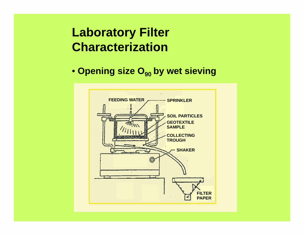
Laboratory Filter Characterization
• Opening size O90 by wet sieving
FEEDING WATER SPRINKLER
SOIL PARTICLESGEOTEXTILE SAMPLE
COLLECTING TROUGH
SHAKER
FILTER PAPER


Permeability criteria
Giroud Criteria Kg > is Ks Where is > 1.0
FWHA Criteria Kgeotextile > FS ksoilallow > FS required
For less critical conditions Kgeotextile > ksoil
For Severe conditions Kgeotextile > 10 ksoil
Min. permittivity conditions > 0.1 to 1 sec-1

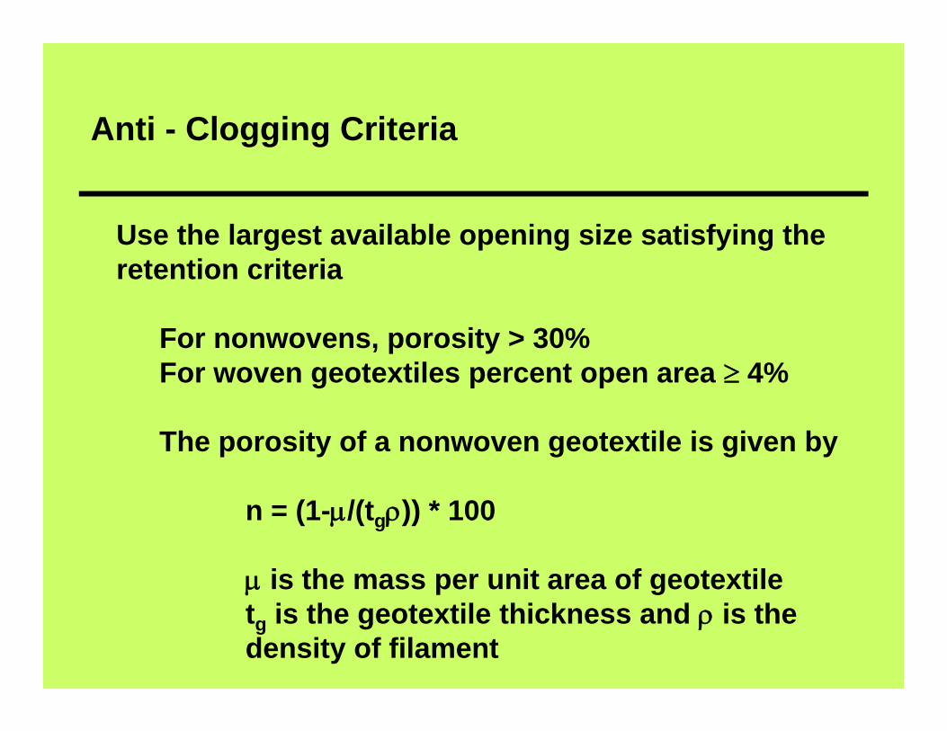
Anti - Clogging Criteria
Use the largest available opening size satisfying the retention criteria
For nonwovens, porosity > 30%For woven geotextiles percent open area 4%
The porosity of a nonwoven geotextile is given by
n = (1-/(tg)) * 100
is the mass per unit area of geotextiletg is the geotextile thickness and is thedensity of filament

Survivability Criteria

Durability Criteria
• Aspects such as geotextiles resistance to ultraviolet and adverse chemical environments need be studied in specific application.
• Exposure to sunlight extensively during must beprotected by anti-oxidants such a carbon black ortitanium oxide.
• Geotextiles should also be resistant to chemicals.