Embed Size (px)
Citation preview
Techniques of Water-Resources Investigations of the United States Geological Survey
Chapter Al4
USE OF FLUMES IN MEASURING DISCHARGE
By F. A. Kilpatrick and V. R. Schneider
Book 3
APPLICATIONS OF HYDRAULICS
USE OF FLUMES IN MEASURING DISCHARGE 19
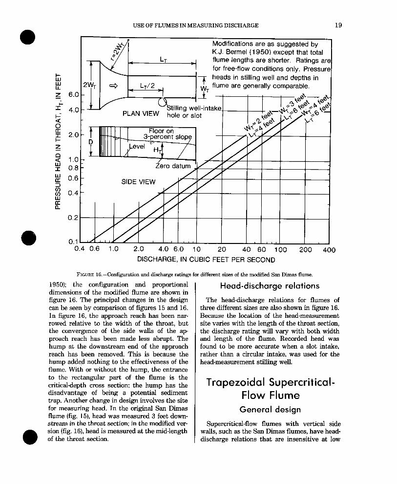
Modifications are as suggested by K.J. Bermel (1950) except that total flume lengths are shorter. Ratings are for free-flow conditions only. Pressure heads in stilling well and depths in
2yT 4 _ LT/2 -1 -f 1 ,,,,- flume are generally comparable.
.f PLAN
SIDE VIEW
0.4 0.6 1 .O 2.0 4.0 6.0 10 20 40 60 100 200 400 DISCHARGE, IN CUBIC FEET PER SECOND
FIGURE 16.-Configuration and discharge ratings for different sizes of the modified San Dimas flume.
1950); the configuration and proportional dimensions of the modified flume are shown in figure 16. The principal changes in the design can be seen by comparison of figures 15 and 16. In figure 16, the approach reach has been nar- rowed relative to the width of the throat, but the convergence of the side walls of the ap- proach reach has been made less abrupt. The hump at the downstream end of the approach reach has been removed. This is because the hump added nothing to the effectiveness of the flume. With or without the hump, the entrance to the rectangular part of the flume is the critical-depth cross section; the hump has the disadvantage of being a potential sediment trap. Another change in design involves the site for measuring head. In the original San Dimas flume (fig. 15), head was measured 3 feet down- stream in the throat section; in the modified ver- sion (fig. 16), head is measured at the mid-length of the throat section.
Head-discharge relations
The head-discharge relations for flumes of three different sizes are also shown in figure 16. Because the location of the head-measurement site varies with the length of the throat section, the discharge rating will vary with both width and length of the flume. Recorded head was found to be more accurate when a slot intake, rather than a circular intake, was used for the head-measurement stilling well.
Trapezoidal Supercritical- Flow Flume
General design
Supercritical-flow flumes with vertical side walls, such as the San Dimas flumes, have head- discharge relations that are insensitive at low
20 TECHNIQUES OF WATER-RESOURCES INVESTIGATIONS
flows. As with Parshall flumes, the rectangular flow section limits the measurable range of dis- charges available for any given size. By sloping the side walls so that the floor width is narrower than the top width at alI cross sections, the sen- sitivity of the rating as welI as the range of discharge that may be accommodated by the flume can be increased.
The most promising design for a trapezoidal supercritical-flow flume was developed by A. R. Chamberlin (1957) and A. R. Robinson (1959). They designed and tested a flume with a throat width of 1 foot at the floor, a depth of 4 feet, a throat slope of 5 percent, and a measurable range of discharge from 1 to 260 ft3/s. This flume is a type IV as previously discussed.
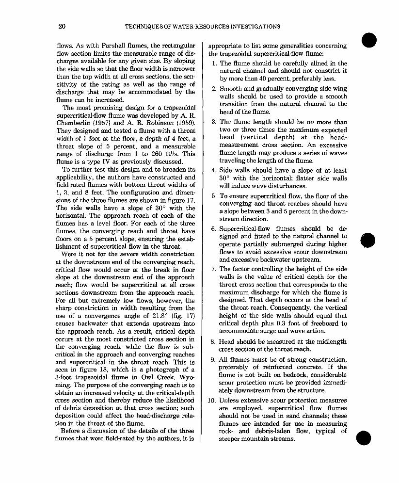
To further test this design and to broaden its applicability, the authors have constructed and field-rated flumes with bottom throat widths of 1, 3, and 8 feet. The configuration and dimen- sions of the three flumes are shown in figure 17. The side walls have a slope of 30” with the horizontal. The approach reach of each of the flumes has a level floor. For each of the three flumes, the converging reach and throat have floors on a 5 percent slope, ensuring the estab- lishment of supercritical flow in the throat.
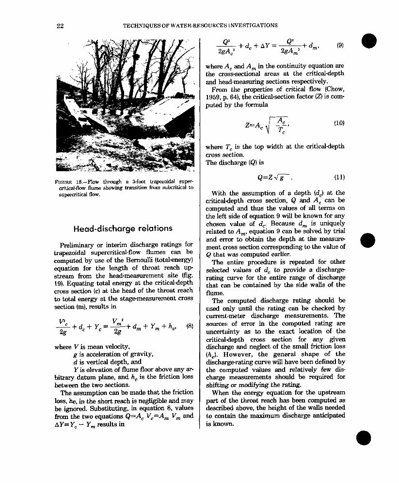
Were it not for the severe width constriction at the downstream end of the converging reach, critical flow would occur at the break in floor slope at the downstream end of the approach reach; flow would be supercritical at all cross sections downstream from the approach reach. For all but extremely low flows, however, the sharp constriction in width resulting from the use of a convergence angle of 21.8 o (fig. 17) causes backwater that extends upstream into the approach reach. As a result, critical depth occurs at the most constricted cross section in the converging reach, while the flow is sub- critical in the approach and converging reaches and supercritical in the throat reach. This is seen in figure 18, which is a photograph of a 3-foot trapezoidal flume in Owl Creek, Wyo- ming. The purpose of the converging reach is to obtain an increased velocity at the critical-depth cross section and thereby reduce the likelihood of debris deposition at that cross section; such deposition could affect the head-discharge rela- tion in the throat of the flume.
Before a discussion of the details of the three flumes that were field-rated by the authors, it is
appropriate to list some generalities concerning the trapezoidal supercritical-flow flume:
1. The flume should be carefully alined in the natural channel and should not constrict it by more than 40 percent, preferably less.
2. Smooth and gradually converging side wing wails should be used to provide a smooth transition from the natural channel to the head of the flume.
3. The flume length should be no more than two or three times the maximum expected head (vertical depth) at the head- measurement cross section. An excessive flume length may produce a series of waves traveling the length of the flume.
4. Side walls should have a slope of at least 30” with the horizontal; flatter side walls will induce wave disturbances.
5. To ensure supercritical flow, the floor of the converging and throat reaches should have a slope between 3 and 5 percent in the down- stream direction.
6. Supercritical-flow flumes should be de- signed and fitted to the natural channel to operate partially submerged during higher flows to avoid excessive scour downstream and excessive backwater upstream.
7. The factor controlling the height of the side walls is the value of critical depth for the throat cross section that corresponds to the maximum discharge for which the flume is designed. That depth occurs at the head of the throat reach. Consequently, the vertical height, of the side walls should equal that critical depth plus 0.3 foot of freeboard to accommodate surge and wave action.
8. Head should be measured at the midlength cross section of the throat reach.
9. All flumes must be of strong construction, preferably of reinforced concrete. If the flume is not built on bedrock, considerable scour protection must be provided immedi- ately downstream from the structure.
10. UnIess extensive scour protection measures are employed, supercritical flow flumes should not be used in sand channels; these flumes are intended for use in measuring rock- and debris-laden flow, typical of steeper mountain streams.
USE OF FLUMES IN MEASURING DISCHARGE 21
1 k 3
6
DIMENSIONS OFTRAPEZOIDALSUPERCRITICAL -FLOW FLUME Width at
Entrance to LENGTHS Flume CAPACITIES FLOOR SLOPES
Converging Approach Converging Throat Height, Min Max* Approach Converglng 8
Reach, WC Reach, Reach, Reach, D (ft)* ft?‘s fts/s Section Throat Section
(fo LA (ft) h vu LT (fi) percent percent
7 350 5** 5 50 , 5.0 1 5.0 1 50 1 4.0 ] 0 9.0 1 Omitted 1 75 1 6.5”*1 5 0 1 1.0 1 700 1 6 1 5
Channel 1 Omltted 1 Variable 1 12.0 I 4 5 I 3.0 I 900 I o I 5
*Maximum discharges correspond to stages approximately 0.5 foot less than D. see text. **OptIonal, may be level, see text
***Throat length tested may have been too short; throat length (LT) of 10 feet IS recommended
ISOMETRIC VIEW
SECTIONAL VIEWS OF GAS-PURGE STAGE MANOMETER SYSTEM
A. Pipe Intake System 6. Gas-purge Stage Manometer System
1. Steel plate, % inch thick
2. Intake slot, % inch wide, smooth-finish
3. Intake pipes, 2%-to 3-inch diameter 4. Steel channel iron set in concrete
5. Steel channel stiffener 6. Steel cover plate with %-inch-diameter
orifice tube (7)
8. Conventional gas line plastic tubing
9 Bolts set to permit removing plate
FIGURE 17.-Configuration, design, and capacities of trapezoidal supercritical-flow flumes.
22 TECHNIQUES OF WATER-RESOURCES l.NVESTIGATIONS
FIGURE l&-Flow through a 3-foot trapezoidal super- critical-flow flume showing transition from subcritical to supercritical flow.
Head-discharge relations
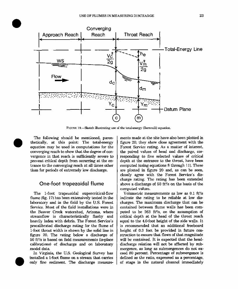
F+x&minary or interim discharge ratings for trapezoidal supercritical-flow flumes can be computed by use of the Bernoulli (totalenergy) equation for the length of throat reach up- stream from the head-measurement site (fig. 19). Equating total energy at the critical-depth cross section (c) at the head of the throat reach to total energy at the stage-measurement cross section (m), results in
- + dc + Yc = vm2 -+ d, + Y, + h,, (8) 2g 2g
where V is mean velocity, g is acceleration of gravity, d is vertical depth, and Y is elevation of flume floor above any ar-
bitrary datum plane, and h, is the friction loss between the two sections.
The assumption can be made that the friction loss, he, in the short reach is negligible and may be ignored. Substituting, in equation 8, values from the two equations Q=A, V,=A, V, and AY= Y, - Y, results in
&” --+dc+AY=---- ‘” +d 2gA$ 2gA,2 m’
(9)
where A, and A, in the continuity equation are the cross-sectional areas at the critical-depth and heed-measuring sections respectively.
From the properties of critical flow (Chow, 1959, p. 64), the critical-section factor (2) is com- puted b;y the formula
(10)
where Tc is the top width at the critical-depth cross section. The discharge (Q) is
Q=Zc.
With the assumption of a depth (d,) at the criticaldepth cross section, Q and A, can be computed and thus the values of all terms on the left side of equation 9 will be known for any chosen value of dc. Because d, is uniquely related to A,, equation 9 can be solved by trial and error to obtain the depth at the measure- ment cross section corresponding to the value of Q that was computed earlier.
The entire procedure is repeated for other selected values of d, to provide a discharge rating curve for the entire range of discharge that can be contained by the side walls of the flume.
The computed discharge rating should be used only until the rating can be checked by current;meter discharge measurements. The s~ources of error in the computed rating are uncertainty as to the exact location of the critical-depth cross section for any given discharge and neglect of the small friction loss (h,). However, the general shape of the dischargerating curve will have been defined by the computed values and relatively few dis- charge measurements should be required for shifting or modifying the rating.
When the energy equation for the upstream part of the throat reach has been computed as described above, the height of the walls needed to contain the maximum discharge anticipated is known.
USE OF FLUMES IN MEASURING DISCHARGE 23
Converging Approach Reach Reach Throat Reach
4 1 .f l
I
4-- -Total-Energy Line
WS -
Flow
dm
Datum Plane
FIGURE lg.-Sketch illustrating use of the total-energy (Bernoulli) equation.
The following should be mentioned, paren- thetically, at this point: The total-energy equation may be used in computations for the converging reach to show that the degree of con- vergence in that reach is sufficiently severe to prevent critical depth from occurring at the en- trance to the converging reach at all times other than for periods of extremely low discharge.
One-foot trapezoidal flume
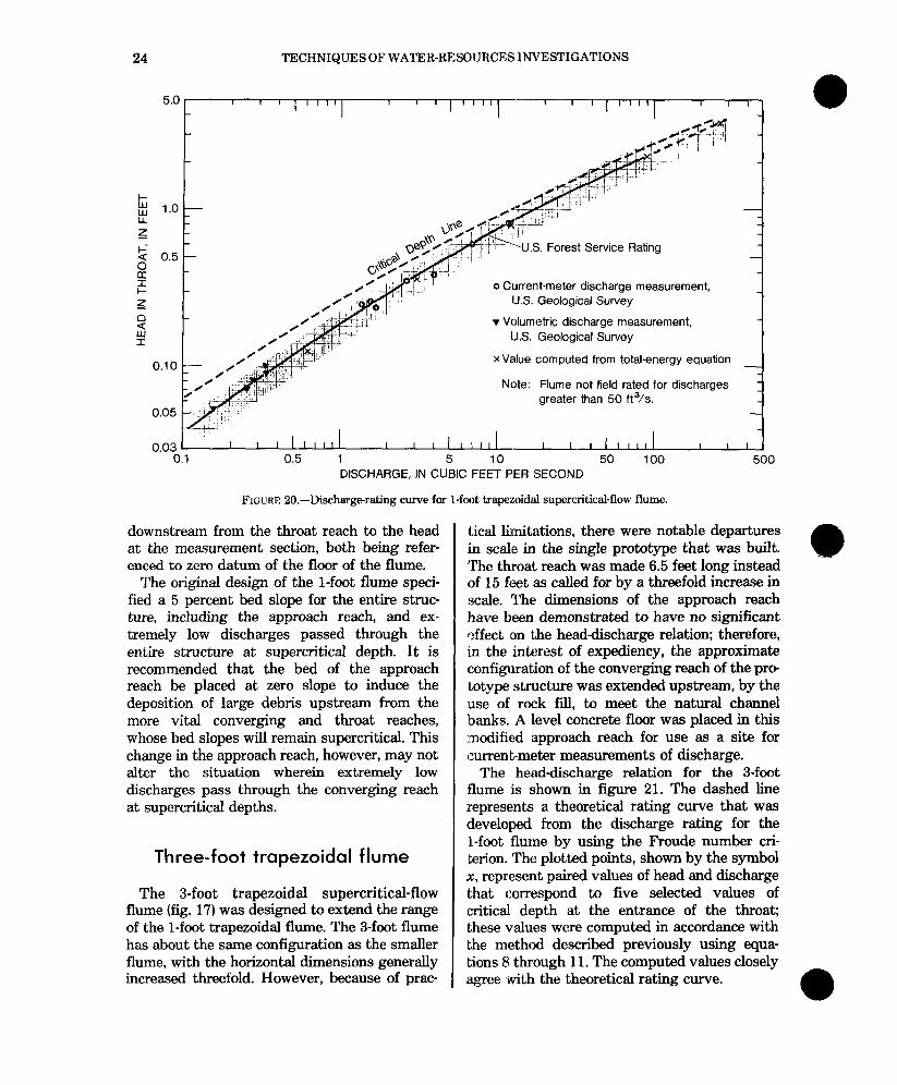
The l-foot trapezoidal supercritical-flow flume (fig. 17) has been extensively tested in the laboratory and in the field by the U.S. Forest Service. Most of the field installations were in the Beaver Creek watershed, Arizona, where streamflow is characteristically flashy and heavily laden with debris. The Forest Service’s precalibrated discharge rating for the flume of l-foot throat width is shown by the solid line in figure 20. The rating below a discharge of 50 ft% is based on field measurements (in-place calibrations) of discharge and on laboratory model data
In Virginia, the U.S. Geological Survey has installed a l-foot flume on a stream that carries only fine sediment. The discharge measure-
ments made at the site have also been plotted in figure 20; they show close agreement with the Forest Service rating. As a matter of interest, the paired values of head and discharge, cor- responding to five selected values of critical depth at the entrance to the throat, have been computed (using equations 8 through 11). These are plotted in figure 20 and, as can be seen, closely agree with the Forest Service’s dis- charge rating. The rating has been extended above a discharge of 50 ft% on the basis of the computed values.
Volumetric measurements as low as 0.1 ftYs indicate the rating to be reliable at low dis- charges. The maximum discharge that can be contained between flume walls has been com- puted to be 263 ftYs, on the assumption of critical depth at the head of the throat reach equal to the 4.0-foot height of the side walls. It is recommended that an additional freeboard height of 0.3 foot be provided in future con- struction to ensure that flows of that magnitude will be contained. It is expected that the head- discharge relation will not be affected by sub- mergence, as long as submergences do not ex- ceed 80 percent. Percentage of submergence is defined as the ratio, expressed as a percentage, of stage in the natural channel immediately
24 TECHNIQUES OF WATER-RESOURCES INVESTIGATIONS
o Current-meter discharge measurement, IJS. Geological Survey
v Volumetric discharge measurement, lJ.S. Geoloaical Survev
x Value computed from total-energy equation
Note: Flume not field rated for discharges greater than 50 ft?s.
1 5 10 50 100 500 DISCHARGE, IN CUBIC FEET PER SECOND
FIGURE 20.-Dischargerating curve for l-foot trapezoidal supercritical-flow flume.
downstream from the throat reach to the head at the measurement section, both being refer- enced to zero datum of the floor of the flume.
The original design of the l-foot flume speci- fied a 5 percent bed slope for the entire struc- ture, including the approach reach, and ex- tremely low discharges passed through the entire structure at supercritical depth. It is recommended that the bed of the approach reach be placed at zero slope to induce the deposition of large debris upstream from the more vital converging and throat reaches, whose bed slopes will remain supercritical. This change in the approach reach, however, may not alter the situation wherein extremely low discharges pass through the converging reach at supercritical depths.
Three-foot trapezoidal flume
The S-foot trapezoidal supercritical-flow flume (fig. 17) was designed to extend the range of the l-foot trapezoidal flume. The 3-foot flume has about the same configuration as the smaller flume, with the horizontal dimensions generally increased threefold. However, because of prac-
tical limitations, there were notable departures in scale in the single prototype that was built. The throat reach was made 6.5 feet long instead of 15 feet as called for by a threefold increase in scale. The dimensions of the approach reach have been demonstrated to have no significant affect Ion the head&charge relation; therefore, in the interest of expediency, the approximate configuration of the converging reach of the pro- totype structure was extended upstream, by the use of rock fill, to meet the natural channel banks. A level concrete floor was placed in this Imodified approach reach for use as a site for current-meter measurements of discharge.
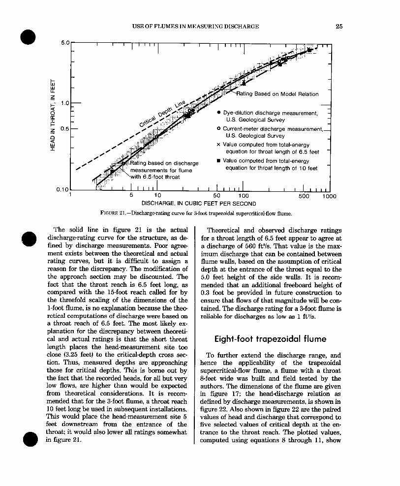
The head-discharge relation for the 3-foot :flume is shown in figure 21. The dashed line represents a theoretical rating curve that was (developed from the discharge rating for the l-foot flume by using the Froude number cri- terion. The plotted points, shown by the symbol X, represent paired values of head and discharge that correspond to five selected values of critical depth at the entrance of the throat; these values were computed in accordance with the method described previously using equa- tions 8 through 11. The computed values closely agree with the theoretical rating curve.
USE OF FLUMES IN MEASURING DISCHARGE 25
rj!k-Rating Based on Model Relation I
0 Dye-dilution discharge measurement, U.S. Geological Survey
0 Current-meter discharge measurement, U.S. Geological Survey
x Value computed from total-energy equation for throat length of 6.5 feet
based on discharge n Value computed from total-energy equation for throat length of 10 feet
DISCHARGE, IN CUBIC FEET PER SECOND
FIGURE 21.-Dischargerating curve for 3-foot trapezoidal supercritical-flow flume.
The solid line in figure 21 is the actual discharge-rating curve for the structure, as de fined by discharge measurements. Poor agree- ment exists between the theoretical and actual rating curves, but it is difficult to assign a reason for the discrepancy. The modification of the approach section may be discounted. The fact that the throat reach is 6.5 feet long, as compared with the 15foot reach called for by the threefold scaling of the dimensions of the l-foot flume, is no explanation because the thee retical computations of discharge were based on a throat reach of 6.5 feet. The most likely ex- planation for the discrepancy between theoreti- cal and actual ratings is that the short throat length places the head-measurement site too close (3.25 feet) to the critical-depth cross sec- tion. Thus, measured depths are approaching those for critical depths. This is borne out by the fact that the recorded heads, for all but very low flows, are higher than would be expected from theoretical considerations. It is recom- mended that for the 3-foot flume, a throat reach 10 feet long be used in subsequent installations. This would place the head-measurement site 5 feet downstream from the entrance of the throat; it would also lower alI ratings somewhat in figure 21.
Theoretical and observed discharge ratings for a throat length of 6.5 feet appear to agree at a discharge of 560 ft3/s. That value is the max- imum discharge that can be contained between flume walls, based on the assumption of critical depth at the entrance of the throat equal to the 5.0 feet height of the side walls. It is recom- mended that an additional freeboard height of 0.3 foot be provided in future construction to ensure that flows of that magnitude will be con- tained. The discharge rating for a 3-foot flume is reliable for discharges as low as 1 ft3/s.
Eight-foot trapezoidal flume
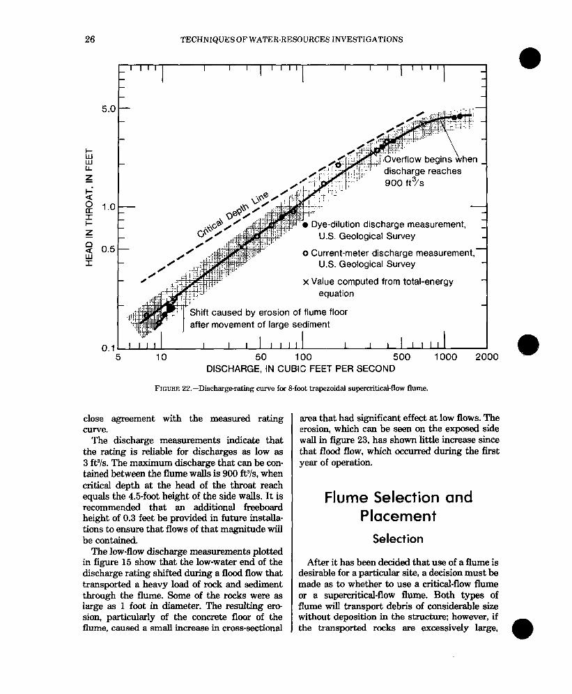
To further extend the discharge range, and hence the applicability of the trapezoidal supercritical-flow flume, a flume with a throat B-feet wide was built and field tested by the authors. The dimensions of the flume are given in figure 17; the head-discharge relation as defined by discharge measurements, is shown in figure 22. Also shown in figure 22 are the paired values of head and discharge that correspond to five selected values of critical depth at the en- trance to the throat reach. The plotted values, computed using equations 8 through 11, show
26 TECHNIQUES OF WATER-RESOURCES INVESTIGATIONS
I III I I I I I II I I I I I II
I
-
Dye-dilution discharge measurement, U.S. Geological Survey
0 Current-meter discharae measurement.-
after movement erosion of large
U.S. Geological Survey
x Value computed from total-energy equation
of flume floor sediment
I I I
50 100 500 DISCHARGE, IN CUBIC FEET PER SECOND
1000
FIGURE 22.-Discharge-rating curve for &foot trapezoidal supercritical-flow flume.
close agreement with the measured rating curve.
The discharge measurements indicate that the rating is reliable for discharges as low as 3 ftYs. The maximum discharge that can be con- tained between the flume walls is 900 ft”/s, when critical depth at the head of the throat reach equals the 4.5-foot height of the side walls. It is recommended that an additional freeboard height of 0.3 feet be provided in future installa- tions to ensure that flows of that magnitude will be contained.
The low-flow discharge measurements plotted in figure 15 show that the low-water end of the discharge rating shifted during a flood flow that transported a heavy load of rock and sediment through the flume. Some of the rocks were as large as 1 foot in diameter. The resulting era sion, particularly of the concrete floor of the flume, caused a small increase in cross-sectional
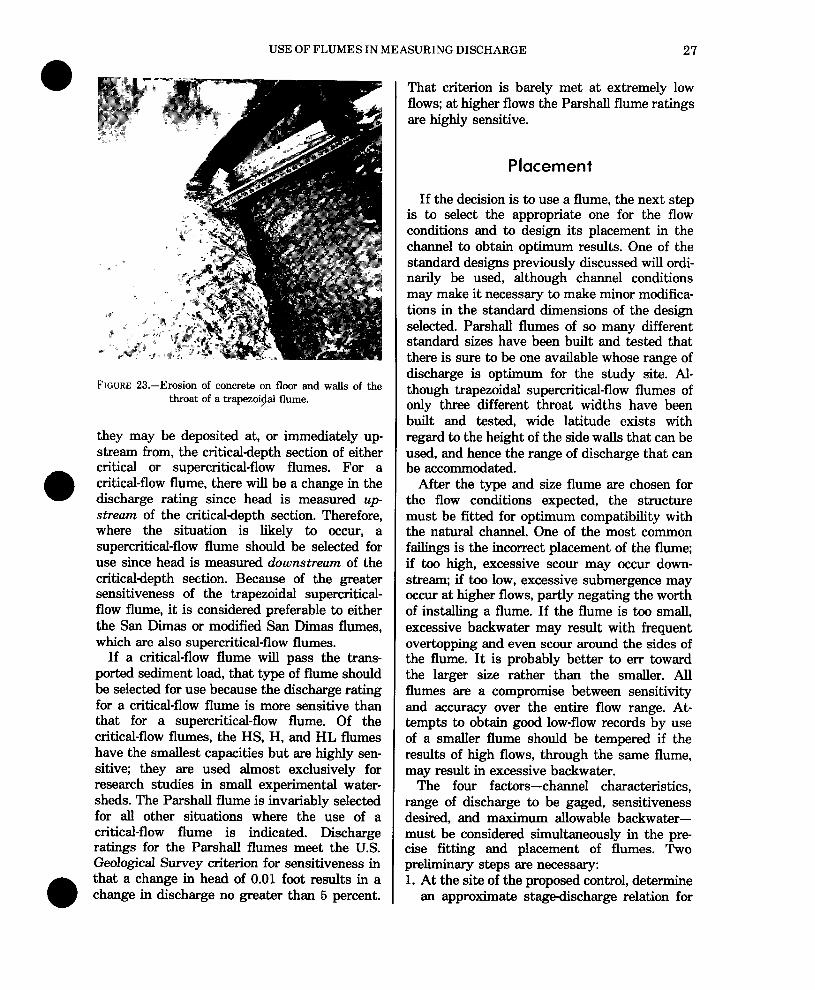
area that had significant effect at low flows. The ‘erosion, which can be seen on the exposed side wall in figure 23, has shown little increase since that flood flow, which occurred during the first year of operation.
Flume Selection and Placement
Selection
After it has been decided that use of a flume is desirable for a particular site, a decision must be made as to whether to use a critical-flow flume or a supercritical-flow flume. Both types of flume will transport debris of considerable size without deposition in the structure; however, if the transported rocks are excessively large,
USE OF FLUMES IN MEASURING DISCHARGE 27
FIGURE 23.-Erosion of concrete on floor and walls of the throat of a trapezoi/dal flume.
they may be deposited at, or immediately up- stream from, the critical-depth section of either critical or supercritical-flow flumes. For a critical-flow flume, there will be a change in the discharge rating since head is measured up- stream of the critical-depth section. Therefore, where the situation is likely to occur, a supercritical-flow flume should be selected for use since head is measured downstream of the critical-depth section. Because of the greater sensitiveness of the trapezoidal supercritical- flow flume, it is considered preferable to either the San Dimas or modified San Dimas flumes, which are also supercritical-flow flumes.
If a critical-flow flume will pass the trans- ported sediment load, that type of flume should be selected for use because the discharge rating for a critical-flow flume is more sensitive than that for a supercritical-flow flume. Of the critical-flow flumes, the HS, H, and HL flumes have the smallest capacities but are highly sen- sitive; they are used almost exclusively for research studies in small experimental water- sheds. The Parshall flume is invariably selected for all other situations where the use of a critical-flow flume is indicated. Discharge ratings for the Parshall flumes meet the U.S. Geological Survey criterion for sensitiveness in
l that a change in head of 0.01 foot results in a change in discharge no greater than 5 percent.
That criterion is barely met at extremely low flows: at higher flows the Parshall flume ratings are highly sensitive.
Placement
If the decision is to use a flume, the next step is to select the appropriate one for the flow conditions and to design its placement in the channel to obtain optimum results. One of the standard designs previously discussed will ordi- narily be used, although channel conditions may make it necessary to make minor modifica- tions in the standard dimensions of the design selected. Parshall flumes of so many different standard sizes have been built and tested that there is sure to be one available whose range of discharge is optimum for the study site. Al- though trapezoidal supercritical-flow flumes of only three different throat widths have been built and tested, wide latitude exists with regard to the height of the side walls that can be used, and hence the range of discharge that can be accommodated.
After the type and size flume are chosen for the flow conditions expected, the structure must be fitted for optimum compatibility with the natural channel. One of the most common failings is the incorrect placement of the flume; if too high, excessive scour may occur down- stream; if too low, excessive submergence may occur at higher flows, partly negating the worth of installing a flume. If the flume is too small, excessive backwater may result with frequent overtopping and even scour around the sides of the flume. It is probably better to err toward the larger size rather than the smaller. All flumes are a compromise between sensitivity and accuracy over the entire flow range. At- tempts to obtain good low-flow records by use of a smaller flume should be tempered if the results of high flows, through the same flume, may result in excessive backwater.
The four factors-channel characteristics, range of discharge to be gaged, sensitiveness desired, and maximum allowable backwater- must be considered simultaneously in the pre- cise fitting and placement of flumes. Two preliminary steps are necessary: 1. At the site of the proposed control, determine
an approximate stage-discharge relation for
28 TECHNIQUES OF WATER-RESOURCES INVESTIGATIONS
the anticipated range in stage in the unob- structed natural channel. This may be done by the use of an openchannel discharge equa- tion, such as the Manning equation (see equa- tion l2), in which uniform flow is assumed for the site and a value of the roughness coeffi- cient is estimated. An initial field survey, in- cluding several cross sections and longitu- dinal profiles for thalweg, existing water sur- face, and bankfull stage, will aid in selecting and fitting the flume. This survey will pro- vide data for the Manning equation as well as a means of assessing the amount of back- water that can be tolerated. The reliability of this approximate stage-discharge relation will be improved if one or more discharge measurements are made to verify the value of the roughness coefficient used in the compu- tations. The purpose of the computations is to determine the tailwater elevation appli- cable to any given discharge after the flume is installed.
2. The head-discharge relations for the several flumes under consideration are next prepared for the anticipated range of discharge. A flume is then selected that best meets the re- quirements of the site, acting as a control for as much of the range as possible and not ex- ceeding the maximum allowable backwater at the higher stages, with minor submer- gence effect and acceptable sensitiveness at lower stages. In other words, a high crest elevation minimizes submergence but maxi- mizes backwater effect that may cause or aggravate flooding; a low crest elevation maximizes the submergence but minimizes backwater effect. Where flumes are con- cerned, the attainment of high sensitiveness at extremely low stages requires a sacrifice in the range of discharge that can be accommo- dated. The engineer must use judgment in selecting a control design that is optimum for the local condition. A note of caution that bears repeating is that
standard artificial controls seldom operate satisfactorily in sand channels with highly mobile beds.
On the pages that follow, sample problems are given to illustrate the selection and place ment of a Par-shall flume and a trapezoidal supercritical-flow flume.
SampIle problem-critical-flow (Parshall flume)
Prob,lem.-Given a channel whose sediment- transport characteristics indicate the desirabil- ity of installing a critical-flow flume (Parshall flume). The range of discharge to be gaged is 4 to 130 ftYs. Freeboard (top of streambank to water surface at maximum discharge) desired is 0.8 to 1.0 foot.
The channel cross section is roughly trapezoi- dal; top width is 12 feet and bottom width is 9 feet. A low-water channel is incised in the streambed; the height from thalweg to top of streambank is 4.3 feet.
Solution.-The first step is to derive an ap- proximate stage-discharge rating for the chan- nel unobstructed by a flume. The rating curve in this example is based on two low-flow discharge measurements and a few values of medium and high discharge computed by means of the Man- ning equation. The Manning equation is
Q= 1.49 J p,3 qz,
n
where Q is discharge, n is roughness coefficient, A is cross-sectional area, R is hydraulic radius, and So is slope.
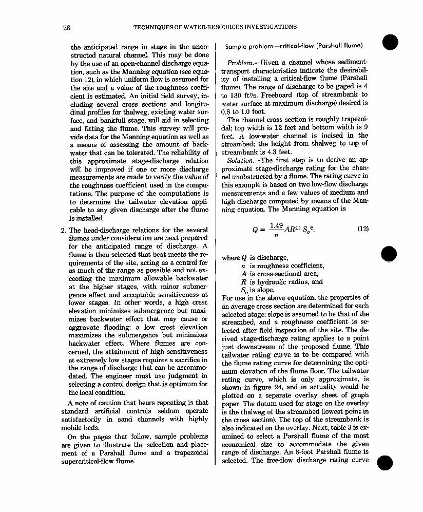
For use in the above equation, the properties of an average cross section are determined for each selected stage; slope is assumed to be that of the streambed, and a roughness coefficient is se lected after field inspection of the site. The de rived stage-discharge rating applies to a point just downstream of the proposed flume. This tailwater rating curve is to be compared with the flume rating curve for determining the opti- mum elevation of the flume floor. The tailwater rating curve, which is only approximate, is shown in figure 24, and in actuality would be plotted on a separate overlay sheet of graph paper. The datum used for stage on the overlay is the thalweg of the streambed (lowest point in the cross section). The top of the streambank is also indicated on the overlay. Next, table 3 is ex- amined to select a Parshall flume of the most economical size to accommodate the given range of discharge. An &foot Parshall flume is selected. The free-flow discharge rating curve
a 4
USE OF FLUMES IN MEASURING DISCHARGE
I I
Top of streambank ---P-P---
Rating curves for 8-pot P?rshall flume
Adjusted for
ree-flow rating with head adjusted by a factor of 0.7
Floor of flume
Thalweg of stream
40 60 80 100 120 140 160
DISCHARGE, IN CUBIC FEET PER SECOND
FIGURE 24.-Method of selection and placement of a Parshall flume control.
for an &foot Par-shall flume is then plotted (fig. 24) using the same coordinate scales as for the tailwater curve, except that datum for the flume floor is selected for free flow at the lowest flows. For higher flows, submergence is permitted, in fact, desirable. At the same time, if feasible, submergence greater than the threshold value of 70 percent for an &foot flume should be avoided. Hence, the freeflow rating curve is also plotted in figure 24, this time using 0.7 times the head for the abscissa.
The overlay bearing the tailwater rating curve is then superposed on the graph sheet bearing the free-flow rating curve for the Par- shah flume. The sheets are positioned so that the two discharge scales coincide and the over- lay is then moved up or down to determine the optimum elevation of the flume floor with respect to the thalweg datum. The best relative position of the two graphs is one which causes the entire tailwater rating curve to lie below the shortdashed curve representing free flow, with head adjusted by a factor of 0.7. The elevation for the flume floor indicated by that positioning would ensure, within the accuracy of the com- puted tailwater rating, no submergence effect
on the Parshall flume rating at any stage (that is, submergence of less than 70 percent).
In this example, if the tailwater rating curve were moved downward from its position shown in figure 24, so as to coincide with the short- dashed curve, at a discharge of 130 ftYs, there would be no submergence effect at any stage, but the freeboard would be reduced to a value smaller than the required 0.8 to 1.0 ft. In view of the uncertainty concerning the accuracy of the tailwater rating curve, caution should be exer- cised in reducing the freeboard requirement because the application of erroneous judgment there may result in a flume installation that causes overbank flooding, when high stages occur during periods of high wind and wave action.
The positioning of the two graphs as shown in figure 24 is believed to indicate the optimum elevation of the flume floor-l.0 foot above the thalweg datum. Submergence effect will occur at discharges greater than 55 ftYs, but the submergence effect is very slight, as will be seen, and a margin for error is still present if in actuality the backwater effect is greater than that computed from the approximate tailwater
30 TECHNIQUES OF WATER-RESOURCES; INVESTIGATIONS
rating curve. At the minimum discharge of The channel cross section is roughly rectangu- 4 ft,Ys, the tailwater stage is 0.5 foot below the lar-the width is 9 feet and the height of the floor of the flume, ensuring free flow at that banks is 7.0 feet. The average slope of the discharge even if aggradation occurs in the streambed is 6 percent and the Manning rough- downstream channel. ness coefficient is 0.050.
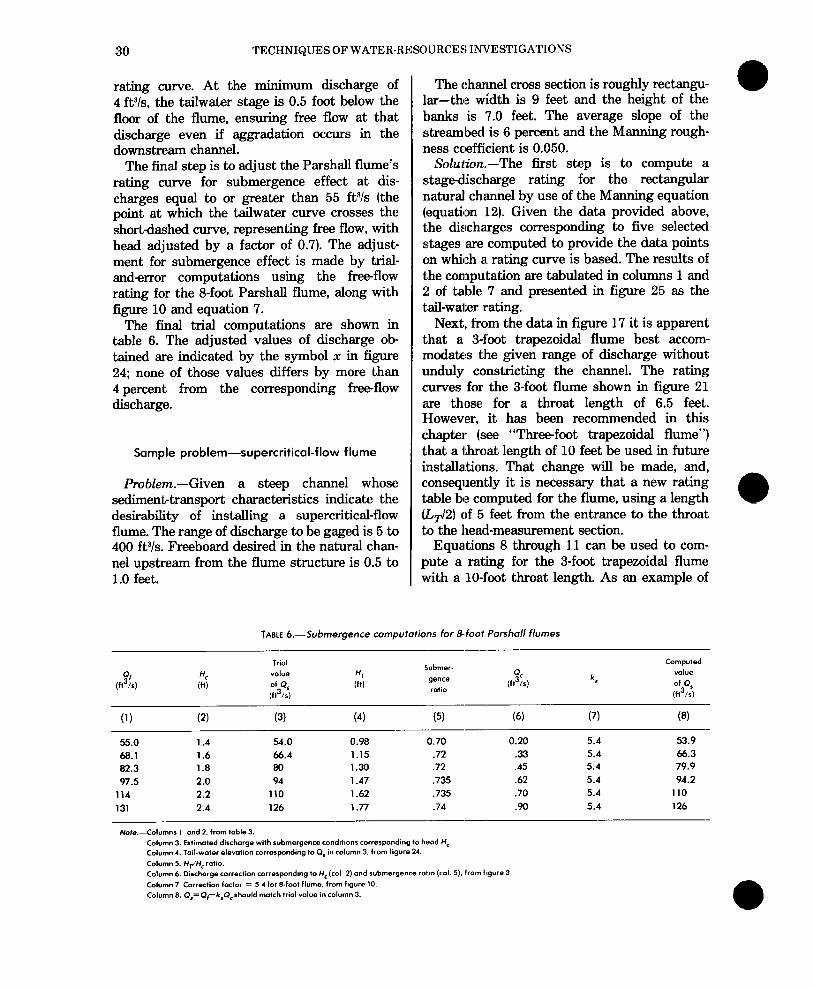
The final step is to adjust the Par-shall flume’s rating curve for submergence effect at dis- charges equal to or greater than 55 ftYs (the point at which the tailwater curve crosses the short-dashed curve, representing free flow, with head adjusted by a factor of 0.7). The adjust- ment for submergence effect is made by trial- anderror computations using the free-flow rating for the &foot Parshall flume, along with figure 10 and equation 7.
The final trial computations are shown in table 6. The adjusted values of discharge ob- tained are indicated by the symbol x in figure 24; none of those values differs by more than 4 percent from the corresponding free-flow discharge.
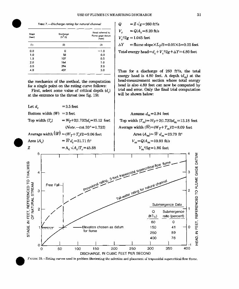
Solution.-The first step is to compute a stage-discharge rating for the rectangular natural channel by use of the Manning equation (equation 12). Given the data provided above, the discharges corresponding to five selected stages are computed to provide the data points on which a. rating curve is based. The results of t,he computation are tabulated in columns 1 and 2! of table 7 and presented in figure 25 as the tail-water rating.
Next, from the data in figure 17 it is apparent that a 3-foot trapezoidal flume best accom- modates the given range of discharge without unduly constricting the channel. The rating curves for the 3-foot flume shown in figure 21 are thlose for a throat length of 6.5 feet. However, it has been recommended in this cfhapter (see “Threefoot trapezoidal flume”) that a throat length of 10 feet be used in future installa.tions. That change will be made, and, consequently it is necessary that a new rating table be computed for the flume, using a length (&/2) of 5 feet from the entrance to the throat to the head-measurement section.
Equations 8 through 11 can be used to com- pute a rating for the 3-foot trapezoidal flume with a lo-foot throat length. As an example of
Sample problem-supercritical-flow flume
Problem.-Given a steep channel whose sediment-transport characteristics indicate the desirability of installing a supercritical-flow flume. The range of discharge to be gaged is 5 to 400 ftYs. Freeboard desired in the natural chan- nel upstream from the flume structure is 0.5 to 1.0 feet.
TABLE 6.--Submergence computations for a-foot Parshall flumes
Trial
value
of q
(f13/5)
I,ubmer-
Qe”Ce
ratio (f,%,
Computed
“OlUe
of OS
(f13/s)
0) (2) (3) (4) (5) (6) (7) (8)
55.0 1.4 54.0 0.98 0.70 0.20 68.1 1.6 66.4 1.15 .72 33 82.3 1.8 80 1.30 .72 .45 97.5 2.0 94 1.47 ,735 .62
114 2.2 110 1.62 ,735 .70 131 2.4 126 1.77 .74 .90
-- Note.--Columns 1 and 2. from table 3.
Column 3. Estimated discharge with submergence condltlons corresponding lo head H, Column 4. Toil-water elevation corresponding lo 0, in column 3. from figure 24.
Column 5. Hr/H,ratio. Column 6. Discharge correCtion correspondmg lo H, (co1 2) and submergence roho (col. 5). from figure 3
Column 7 Correction factor = 5 1 for s-foot flume. from figure 10.
Column 8. Q,=Q,-k,Q,should match trio1 value in column 3.
5.4 53.9 5.4 66.3 5.4 79.9 5.4 94.2 5.4 110 5.4 126
USE OF FLUMES IN MEASURING DISCHARGE 31
TABLE 7.--Discharge rating for natural channel
Dtrchorge (f13/3)
Head referred to flume gage datum
(feet)
(1) (2) (3)
0.0 0 -1.0 1.0 58 0.0 1.5 107 0.5 2.0 164 1.0 3.0 294 2.0 4.0 437 3.0
the mechanics of the method, the computation for a single point on the rating curve follows:
First, select some value of critical depth (d,) at the entrance to the throat (see fig. 19):
Let d, = 3.5 feet,
Bottom width (IV) =3 feet
Top width (Z’,) = WT+2(1.732)dC=15.12 feet
(Note.-cot 30”=1.732)
Average width (v) = (W,+Z’,)/2=9.06 feet
An.33 CA,) = vd,=31.71 ft2
z = A, ~A,IT,=45.88
Q = Z -\/g=260 ftYs
vc = Q/A,=8.20 ftls
VJ2g = 1.045 feet
AY =flume slopeXLT12=0.05X5=0.25 feet
Total energy head=d,+ V,YBg+ AY=4.80 feet
Thus for a discharge of 260 ftYs, the total energy head is 4.80 feet. A depth (d,) at the head-measurement section whose total energy head is also 4.80 feet can now be computed by trial and error. Only the final trial computation will be shown below:
Assume d,,,=2.94 feet
Top width (T,)=WT+2(l.732)d,=13.18 feet
Average width (~=(W,+T,)/2=8.09 feet
Area (Am)= w d,=23.79 ft?
V,=Q/A,=10.93 ft/s
V,,,Y2g=1.86 feet 5 5 4 4 5
2
E E d 3 3 2 2
z 4- 4-
-3 3
z z s
r” 3 ii
-2 0 I-
B 0
Submergence Data Submergence Data -1 -1
5
Q Q Submergence Submergence B
o-&) o-&) ratio (percent) ratio (percent) :: cc
60 60 0 0 kl -Elevation chosen -Elevation chosen as datum as datum 150 150 41 41 -0 -0 if
for flume for flume 250 250 59 59 z 400 400 76 76 2
-1 F 0 0 50 50 100 150 100 150 200 200 250 250 300 300 350 350 400 400
DISCHARGE, IN CUBIC FEET PER SECOND DISCHARGE, IN CUBIC FEET PER SECOND FIGURE 25.-Rating curves used in problem illustrating the selection and placement of trapezoidal supercritical-flow flun FIGURE 25.-Rating curves used in problem illustrating the selection and placement of trapezoidal supercritical-flow flume. ne.
32 TECHNIQUES OF WATER-RESOURCES INVESTIGATIONS
Total energy head=d,S V,,,Y2g=4.80 feet
The assumed depth (d,) gives a total energy head that matches that for the critical-depth cross section; therefore, for a discharge of 260 ft31s the stage is 2.94 feet.
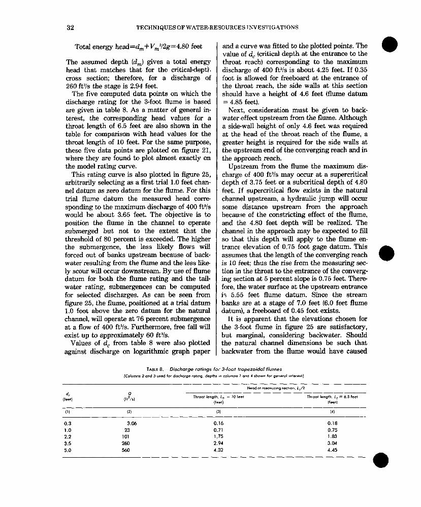
The five computed data points on which the discharge rating for the 3-foot flume is based are given in table 8. As a matter of general in- terest, the corresponding head values for a throat length of 6.5 feet are also shown in the table for comparison with head values for the throat length of 10 feet. For the same purpose, these five data points are plotted on figure 21, where they are found to plot almost exactly on the model rating curve.
This rating curve is also plotted in figure 25, arbitrarily selecting as a first trial 1.0 feet chan- nel datum as zero datum for the flume. For this trial flume datum the measured head corre sponding to the maximum discharge of 400 ftYs would be about 3.65 feet. The objective is to position the flume in the channel to operate submerged but not to the extent that the threshold of 80 percent is exceeded. The higher the submergence, the less likely flows will forced out of banks upstream because of back- water resulting from the flume and the less like ly scour will occur downstream. By use of flume datum for both the flume rating and the tail- water rating, submergences can be computed for selected discharges. As can be seen from figure 25, the flume, positioned at a trial datum 1.0 foot above the zero datum for the natural channel, will operate at ‘76 percent submergence at a flow of 400 ftYs. Furthermore, free fall will exist up to approximately 60 ft”/s.
Values of d, from table 8 were also plotted against discharge on logarithmic graph paper
and a Curve was fitted to the plotted points. The value of d, (critical depth at the entrance to the throat reach) corresponding to the maximum discharge of 400 ftYs is about 4.25 feet. If 0.35 foot is allowed for freeboard at the entrance of the throat reach, the side walls at this section should have a height of 4.6 feet (flume datum = 4.85 feet).
Next, consideration must be given to back- water effect upstream from the flume. Although a side-wall height of only 4.6 feet was required .at the head of the throat reach of the flume, a greater height is required for the side walls at the upstream end of the converging reach and in the approach reach.
Upstream from the flume the maximum dis- charge of 400 ftYs may occur at a supercritical depth of 3.75 feet or a subcritical depth of 4.80 feet. If supercritical flow exists in the natural channel upstream, a hydraulic jump will occur some distance upstream from the approach because of the constricting effect of the flume, and the 4.80 feet depth will be realized. The channel in the approach may be expected to fill so that this depth will apply to the flume en- trance elevation of 0.75 foot gage datum. This assumes that the length of the converging reach is 10 feet: thus the rise from the measuring sec- tion in the throat to the entrance of the converg- ing section at 5 percent slope is 0.75 feet. There fore, the water surface at the upstream entrance is 5.5’5 feet flume datum. Since the stream banks are at a stage of 7.0 feet (6.0 feet flume datum), a freeboard of 0.45 foot exists.
It is apparent that the elevations chosen for the 3-foot flume in figure 25 are satisfactory, but marginal, considering backwater. Should the natural channel dimensions be such that backwater from the flume would have caused
TAME 8.-Discharge ratings for- 3-foot trapezoidal flumes (Columns 2 and 3 used for discharge rotmg. depths in columns I and 4 shown for general mterertl
4 Q
(f=-+ (f13/r)
Head a+ measurmg section. LT/2 --
Throat length. Iv = IO leet Throat length. IT = 6.5 feet
(feet) (feet)
(1) (2) 0) (4) --
0.3 3.06 0.16 0.18 1.0 23 0.71 0.75 2.2 101 1.75 1.83 3.5 260 2.94 3.04 5.0 560 A.32 4.45
--
USE OF FLUMES IN MEASURING DISCHARGE 33
a overflow into the flood plains or over and around the flume, a larger flume might have been selected. In any case, the placement of the flume should be such as to operate with a high degree of submergence.
With regard to sensitiveness, at a minimum discharge of 5 ftYs, the flume discharge rating meets the criterion of having no more than 5 percent change in discharge for a change of 0.01 foot in head.
Construction of Flumes
General
The portable Parshall flume and the HS, H, and HL flumes may be built of sheet metal or metal plate. The Par-shall, San Dimas, modified San Dimas, and the trapezoidal supercritical- flow flumes are usually built of reinforced con- crete, but concrete block, steel, wood, and fiberglass have also been used on occasion.
Flume dimensions, especially those of the throat reaches, must be carefully adhered to if
e
precalibrated discharge ratings are to be used. Upon completion of a new flume, the throat dimensions should be carefully measured and discharge ratings adjusted. For the trapezoidal supercritical-flow flume, a new rating should be computed using the actual in-place dimensions, if they differ from the standard sizes. The com- plicated configuration of the trapezoidal flume approach and converging sections need not be rigidly adhered to as long as reasonable care is exercised to produce a smooth transition from subcritical to supercritical flow. Abrupt en- trances may cause flow separation in the throat section and affect the depth at the measuring section.
Flumes must be solidly built in streams with high-velocity flow, laden with heavy sediment and debris. The high velocities exert uplift forces of considerable magnitude on the struc- tures, and also cause scour in, and downstream from, the flumes. Good concrete and concreting techniques must be used if erosion of the flume throat is to be avoided. Two methods have been employed in the construction of the trapezoidal supercritical flow flume: (1) prefabrication for assembly at the site and (2) cast-in-place con-
8
struction where premixed concrete could be ac- quired and used at an accessible site.
Prefabricated construction
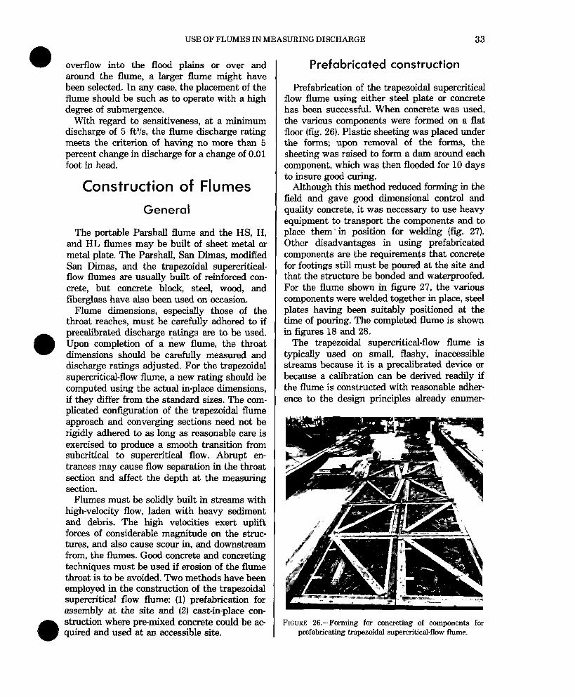
Prefabrication of the trapezoidal supercritical flow flume using either steel plate or concrete has been successful. When concrete was used, the various components were formed on a flat floor (fig. 26). Plastic sheeting was placed under the forms; upon removal of the forms, the sheeting was raised to form a dam around each component, which was then flooded for 10 days to insure good curing.
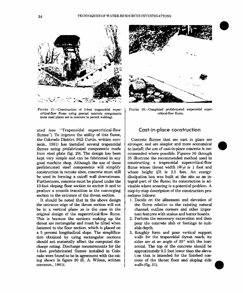
Although this method reduced forming in the field and gave good dimensional control and quality concrete, it was necessary to use heavy equipment to transport the components and to place them’ in position for welding (fig. 27). Other disadvantages in using prefabricated components are the requirements that concrete for footings still must be poured at the site and that the structure be bonded and waterproofed. For the flume shown in figure 27, the various components were welded together in place, steel plates having been suitably positioned at the time of pouring. The completed flume is shown in figures 18 and 28.
The trapezoidal supercritical-flow flume is typically used on small, flashy, inaccessible streams because it is a precalibrated device or because a calibration can be derived readily if the flume is constructed with reasonable adher- ence to the design principles already enumer-
FIGURE 26.-Forming for concreting of components for prefabricating trapezoidal supercritical-flow flume.
TECHNIQUES OF WATER-RESOURCES INVESTIGATIONS
FIGURE 27.-Construction of 3-foot trapezoidal super- critical-flow flume using precast concrete components (note steel plates set in concrete to permit welding).
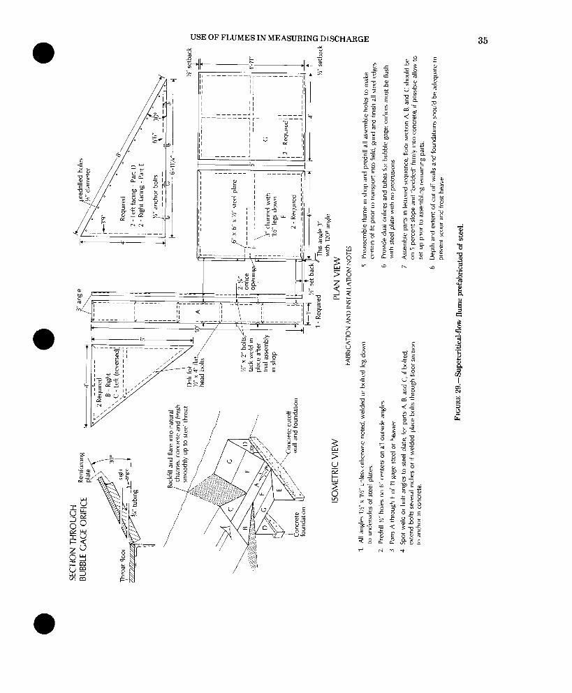
ated (see “Trapezoidal supercritical-flow flumes”). To improve the utility of this flume, the Colorado District (Bill Curtis, written com- mun., 1981) has installed several trapezoidal flumes using prefabricated components made from steel plate (fig. 29). The design has been kept very simple and can be fabricated in any good machine shop. Although the use of these prefabricated steel components will simplify construction in remote sites, concrete must still be used in forming a cutoff wall downstream. Furthermore, concrete must be placed under the lo-foot sloping floor section to anchor it and to produce a smooth transition in the converging section to the entrance of the throat section.
It should be noted that in the above design the entrance edge of the throat section will not be in a vertical plane as is the case in the original design of the supercritical-flow flume. This is because the sections making up the throat are rectangular and must be tilted when fastened to the floor section, which is placed on a 5 percent longitudinal slope. The simplifica- tion obtained by using rectangular sections should not materially affect the computed dis- charge rating. Discharge measurements for the l-foot prefabricated flumes installed in Cole rado were found to be in agreement with the rat- ing shown in figure 20 (E. A. Wilson, written commun., 1981).
FIGURE: 28.-Completed prefabricated trapezoidal super- critical-flow flume.
Cast-in-place construction
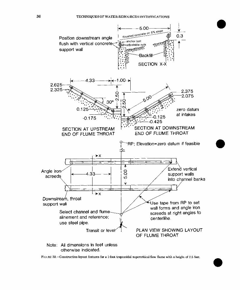
Concrete flumes that are cast in place are stronger, and are simpler and more economical to install; the use of cast-in-place concrete is rec- ommended where possible. Figures 30 through 35 illustrate the recommended method used in constructing a trapezoidal supercritical-flow flume whose throat width @VT) is 1 foot and whose height (0) is 2.5 feet. An energy- dissipation box was built at the site as an in- tegral part of the flume; its construction is ad- visable where scouring is a potential problem. A step-by-step description of the construction pm cedures follows:
1. Decide on the alinement and elevation of the flume relative to the existing natural channel; outline comers and other impor- timt features with stakes and batter boards.
2. Perform the necessary excavation and then pour the concrete slab or footings to suit- a’ble depth.
3. Roughly form and pour vertical support walls for the trapezoidal throat reach; its sides are at an angle of 30” with the hori- zontal. The top of the concrete should be approximately 0.3 foot lower than the eleva- tion that is intended for the finished con- crete of the throat floor and sloping side walls (fig. 31).
USE OF FLUMES IN MEASURING DISCHARGE 35
v a
36 TECHNIQUES OF WATER-RESOURCES INVESTIGATIONS
Position down.c+---- ---In flush with vertical concrete?@!& support wall
3lIaalll a IyE F,llS
/ h. -anchor bolt
Padiustable nuts +
2.625 2.325
SECTION AT UPSTREAM p vA-o- -SECTION AT DOWNSTREAM END OF FLUME THROAT E!ND OF FLUME THROAT
r-RP; Elevation=zero datum if feasible
support wall
Select channel and flum reference; alinement and
use steel pipe.
Transit or leve
se tape from RP to set all forms and angle iron
screeds at right angles to centerline.
PLAN VIEW SHOWING LAYOUT OF FLUME THROAT
Note: All dimensions in feet unless otherwise indicated.
FIGURE 30.-Construction layout features for a l-foot trapezoidal supercritical-flow flume with a height of 2.5 feet.
a
USE OF FLUMES IN MEASURING DISCHARGE 37
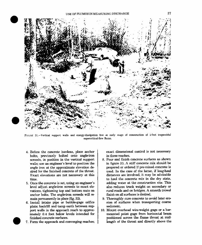
FIGURE 31.--Vertical support wslls and energy-dissipation box at early stage of construction of l-foot trapezoidal supercritical-flow flume.
4. Before the concrete hardens, place anchor bolts, previously bolted onto angle-iron screeds, in position in the vertical support walls; use an engineer’s level to position the angle iron at the approximate elevation de sired for the finished concrete of the throat. Exact elevations are not necessary at this time.
5.
6.
Once the concrete is set, using an engineer’s level adjust angle-iron screeds to exact ele- vations, tightening top and bottom nuts on anchor bolts. The angleiron screeds will IX+ main permanently in place (fig. 32). Install intake pipe or bubble-gage orifice plate; backfill and tamp earth between sup- port walls in the approach reach to approx- imately 0.4 foot below levels intended for finished concrete surfaces.
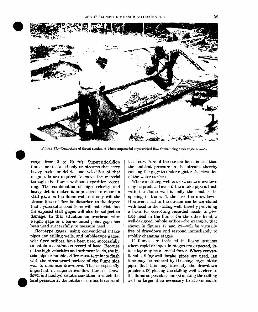
7. Form the approach and converging reaches;
exact dimensional control is not necessary in these reaches. Pour and finish concrete surfaces as shown in figure 33. A stiff concrete mix should be prepared or ordered if premixed concrete is used. In the case of the latter, if long-haul distances are involved, it may be advisable to haul the concrete mix in the dry state, adding water at the construction site. This also reduces truck weight on secondary or rural roads and on bridges. A smooth trowel finish on alI surfaces is desired. Thoroughly cure concrete to avoid later era sion of surfaces when transporting coarse sediment. Mount overhead wireweight gage or a bar- mounted point gage from horizontal beam positioned across the flume throat at mid- length of the throat and directly above the
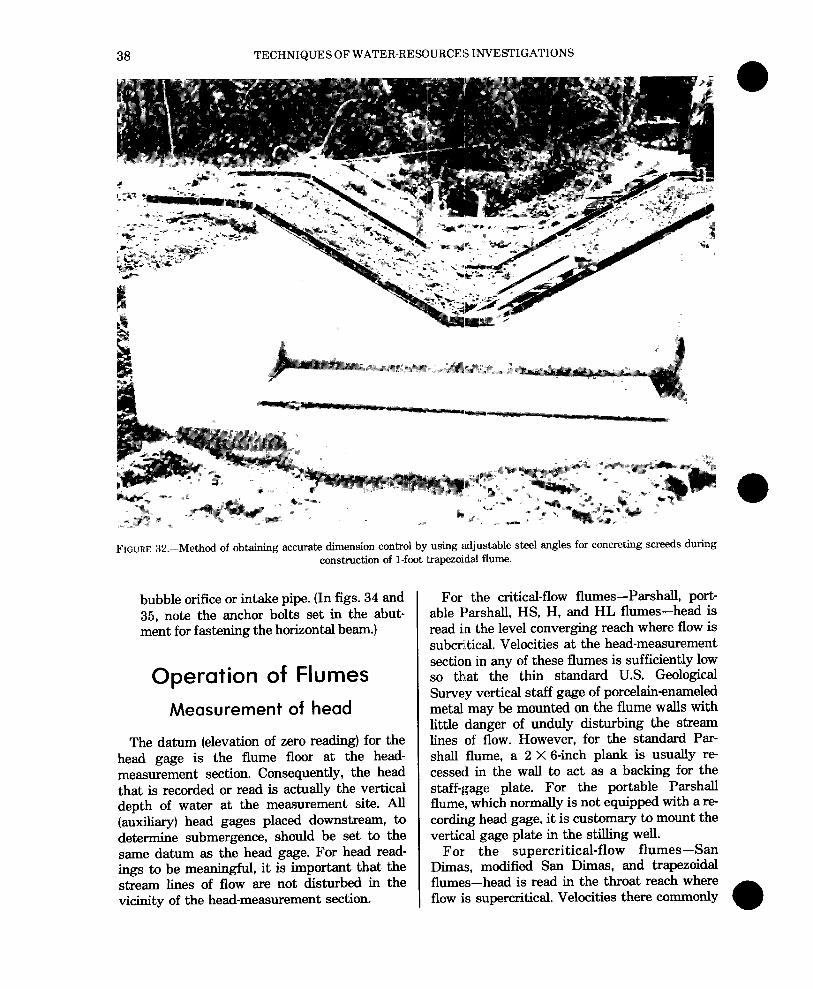
38 TECHNIQUES OF WATER-RESOURCE8 INVESTIGATIONS
FIGURE 32.-Method of obtaining accurate dimension control by using adjustable steel angles for concreting screeds during construction of l-foot trapezoidal flume.
bubble orifice or intake pipe. (In figs. 34 and 35, note the anchor bolts set in the abut- ment for fastening the horizontal beam.)
Operation of Flumes
Measurement of head
The datum (elevation of zero reading) for the head gage is the flume floor at the head- measurement section. Consequently, the head that is recorded or read is actually the vertical depth of water at the measurement site. All (auxiliary) head gages placed downstream, to determine submergence, should be set to the same datum as the head gage. For head read- ings to be meaningful, it is important that the stream lines of flow are not disturbed in the vicinity of the head-measurement section.
For the critical-flow flumes--Par-shall, port- able Parshah, HS, H, and HL flumes-head is read in the level converging reach where flow is subcritical. Velocities at the head-measurement section in any of these flumes is sufficiently low so that the thin standard U.S. Geological Survey vertical staff gage of porcelainenameled metal may be mounted on the flume walls with little danger of unduly disturbing the stream lines of flow. However, for the standard Par- shall flume, a 2 X 6-inch plank is usually re- cessed in the wall to act as a backing for the staff-gage plate. For the portable Par-shall flume, which normally is not equipped with a re cording head gage, it is customary to mount the vertical gage plate in the stilling well.
For the supercritical-flow flumes-San Dimas, modified San Dimas, and trapezoidal flumes-head is read in the throat reach where flow is supercritical. Velocities there commonly
USE OF FLUMES IN MEASURING DISCHARGE 39
0 FIGURE 33.-Concreting of throat section of l-foot trapezoidal supercritical-flow flume using steel angle screeds.
range from 3 to 20 ft/s. Sunercritical-flow local curvature of the stream lines, is less than the ambient pressure in the stream, thereby causing the gage to under-register the elevation of the water surface.
flumes are installed only on streams that carry heavy rocks or debris, and velocities of that magnitude are required to move the material through the flume without deposition occur- ring. The combination of high velocity and heavy debris makes it impractical to mount a staff gage on the flume wall; not only will the stream lines of flow be disturbed to the degree that hydrostatic conditions will not exist, but the exposed staff gages will also be subject to damage. In that situation an overhead wire- weight gage or a bar-mounted point gage has been used successfully to measure head.
Float-type gages, using conventional intake pipes and stilling wells, and bubble-type gages, with fixed orifices, have been used successfully to obtain a continuous record of head. Because of the high velocities and sediment loads, the in- take pipe or bubble orifice must terminate flush with the streamward surface of the flume side wall to minimize clrawdown. This is especially important in supercritical-flow flumes. Draw- down is a nonhydrostatic condition in which the
0 local pressure at the intake or orifice, because of
Where a stilling well is used, some drawdown may be produced even if the intake pipe is flush with the flume wall (usually the smaller the opening in the wall, the less the drawdown). However, head in the stream can be correlated with head in the stilhng well, thereby providing a basis for correcting recorded heads to give true head in the flume. On the other hand, a well-designed bubble orifice-for example, that shown in figures 17 and 29-will be virtually free of drawdown and respond immediately to rapidly changing stages.
If flumes are installed in flashy streams where rapid changes in stages are expected, in- take lag may be a crucial factor. Where conven- tional stilling-well intake pipes are used, lag time may be reduced by (1) using large intake pipes (but this may intensify the drawdown problem); (2) placing the stilling well as close to the flume as possible; and (3) making the stilling well no larger than necessary to accommodate
40 TECHNIQUES OF WATER-RESOURCES INVESTIGATIONS
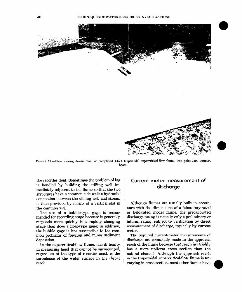
a FIGURE 34.-View looking downstream at completed l-foot trapezoidal supercritical-flow flume, less point-gage support
beam.
the recorder float. Sometimes the problem of lag is handled by building the stilling well im- mediately adjacent to the flume so that the two structures have a common side wall; a hydraulic connection between the stilling well and stream is then provided by means of a vertical slot in the common wsll.
The use of a bubbletype gage is recom- mended for recording stage because it generally responds more quickly to a rapidly changing stage than does a float-type gage; in addition, the bubble gage is less susceptible to the com- mon problems of freezing and minor sediment deposition.
In the supercritical-flow flume, one difficulty in measuring head that cannot be surmounted, regardless of the type of recorder used, is the turbulence of the water surface in the throat reach.
Current-meter measurement of discharge
Although flumes are usually built in accord- ance with the dimensions of a laboratory-rated or field-rated model flume, the precalibrated discharge rating is usually only a preliminary or interim rating, subject to verification by direct measurement of discharge, typically by current meter.
The required current-meter measurements of discharge are commonly made in the approach reach of the flume because that reach invariably has a more uniform cross section than the natural channel. Although the approach reach in the trapezoidal supercritical-flow flume is un- varying in cross section, most other flumes have
USE OF FLUMES IN MEASURING DISCHARGE 41
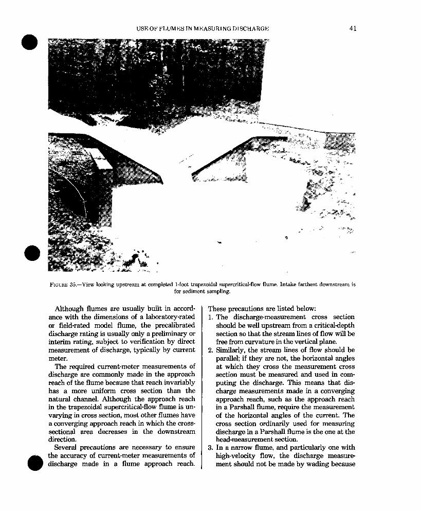
FIGURE 35.-View looking upstream at completed l-foot trapezoidal supercritical-flow flume. Intake farthest downstream is for sediment sampling.
Although flumes are usually built in accord- ance with the dimensions of a laboratory-rated or field-rated model flume, the precalibrated discharge rating is usually only a preliminary or interim rating, subject to verification by direct measurement of discharge, typically by current meter.
The required current-meter measurements of discharge are commonly made in the approach reach of the flume because that reach invariably has a more uniform cross section than the natural channel. Although the approach reach in the trapezoidal supercritical-flow flume is un- varying in cross section, most other flumes have a converging approach reach in which the cross- sectional area decreases in the downstream direction.
Several precautions are necessary to ensure the accuracy of current-meter measurements of discharge made in a flume approach reach.
These precautions are listed below: 1. The dischargemeasurement cross section
should be well upstream from a critical-depth section so that the stream lines of flow will be free from curvature in the vertical plane.
2. Similarly, the stream lines of flow should be paralleh if they are not, the horizontal angles at which they cross the measurement cross section must be measured and used in com- puting the discharge. This means that dis- charge measurements made in a converging approach reach, such as the approach reach
I in a Par-shall flume, require the measurement of the horizontal angles of the current. The cross section ordinarily used for measuring discharge in a Par-shall flume is the one at the head-measurement section.
3. In a narrow flume, and particularly one with high-velocity flow, the discharge measure ment should not be made by wading because
42 TECHNIQUES OF WATER-RESOURCES INVESTIGATIONS
of the interference to flow offered by the stream-gager’s body. The measurement should be made from a bridge or plank across the top of the flume, using the current meter suspended from a rod. If velocities are high, the conventional method of measuring depth will be inaccurate because of water pileup on the rod. In this case, obtain differences in rod readings at index points on the bridge or plank (1) when the base plate of the rod is positioned at the water surface and (2) when the base plate rests on the floor of the flume.
4. When the floor of the approach reach is uniformly level, as it generally is, depths should be read to hundredths of a foot rather than to the nearest tenth of a foot, as is done in natural channels. If the uniform depths are rounded to the nearest tenth of a foot, a bias will be introduced into the computed discharge.
5. Widths should be measured accurately to the nearest tenth of a foot using a graduated tape rather than a tag line whose smallest gradua- tions are 2-foot markers. The wading rod is normally held at the tag line, which thereby places the rotor of the meter upstream from the tag line. In a cross section through the center of the rotor, positioning may be signif- icantly greater than the widths at the wading rod positioning. The width at the rotor posi- tioning should be used.
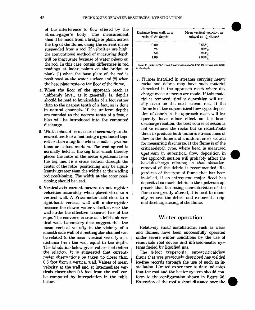
6. Vertical-axis current meters do not register velocities accurately when placed close to a vertical wall. A Price meter held close to a right-bank vertical wall will under-register because the slower water velocities near the wall strike the effective (concave) face of the cups. The converse is true at a left-bank ver- tical wall. Laboratory data suggest that the mean vertical velocity in the vicinity of a smooth side wall of a rectangular channel can be related to the mean vertical velocity at a distance from the wall equal to the depth. The tabulation below gives values that define the relation. It is suggested that current- meter observations be taken no closer than 0.5 foot from a vertical wall. Values of mean velocity at the wall and at intermediate ver- ticals closer than 0.5 foot from the wall can be computed by interpolation in the table below.
-- Distance from wall. as a
ratio of the depth Mean vertical velocity, as
@
related to V, offs)
0.00 0.65V, .25 .9ov, .50 .95v*
1.00 I.OOV,
Note VD is to the dqh
the Lnean vertical v&city at a distance from the vertical wall equal
7. Flumes installed in streams carrying heavy rocks and debris may have such material deposited in the approach reach where dis- charge measurements are made. If this mate- rial is removed, similar deposition will usu- ally occur on the next stream rise. If the flume is of the supercritical-flow type, deposi- tion of debris in the approach reach will fre- quently have minor effect on the head- discharge relation; the best course of action is not to remove the rocks but to redistribute them to produce both uniform stream lines of flow in the flume and a uniform cross section for measuring discharge. If the flume is of the critical-depth type, where head is measured upstream in subcritical flow, deposition in the approach section will probably affect the headdischarge relation; in that situation, removal of the debris is recommended. Re gardless of the type of flume that has been installed, if an infrequent major flood has deposited so much debris in the upstream ap- prcoach that the rating characteristics of the fltlme are greatly altered, it is best to manu- ally remove the debris and restore the orig- inal discharge rating of the flume.
Winter operation
Relatively small installations, such as weirs and flumes, have been successfully operated under severe winter conditions by the use of removable roof covers and infrared-heater sys- tems fueled by liquified gas.
The S-foot trapezoidal supercritical-flow flume that was previously described has yielded ice-free records through the use of such an in- stallation. Limited experience to date indicates that the roof and the heater system should con- form to the configuration shown in figure 36. Extension of the roof a short distance over the
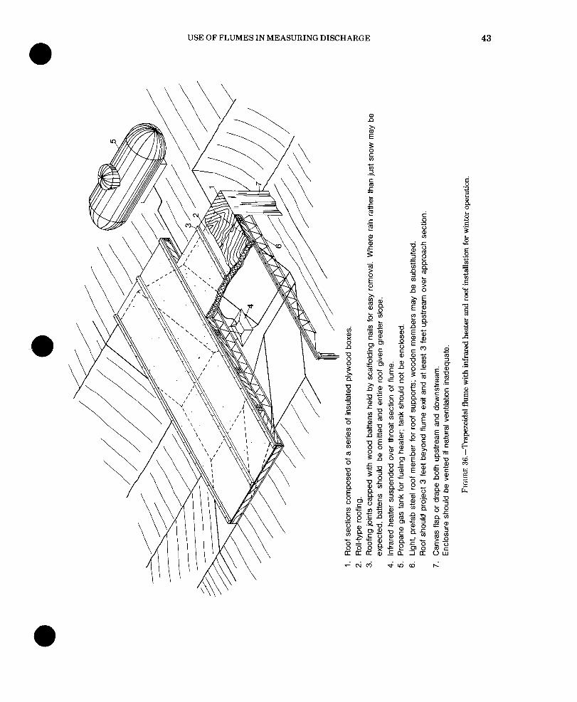
USE OF FLUMES IN MEASURING DISCHARGE 43
-
44 TECHNIQUES OF WATER-REBOURCE:S INVESTIGATIONS
approach section provides an ice-free measuring section. The size of the infrared heater and gas tank depend on local climatic conditions and ex- posure. Cost of operation will generally range from $1.00 to $2.00 per day (1981).
Precalibrated Discharge Ratings Versus In-Place
Calibrations When a flume is installed in a stream, it is
usually built in conformance with the dimen- sions of one that has been precalibrated. The question then arises whether to use the precali- brated rating for the new structure or to cali- brate the structure in place. There are two schools of thought on the subject.
In many countries the precalibrated dis- charge rating is accepted, and independent dis- charge measurements are made only periodi- cally to determine whether any statistically significant changes in the rating have occurred. If a significant change is detected, the new rating is defined by as many discharge measure- ments as are deemed necessary.
The Water Resoures Division takes the posi- tion that it is seldom desirable to accept the precalibrated rating without checking the entire rating in the field by current-meter measure- ments or by other methods of measuring dis- charge. Experience in the United States and elsewhere has been that, in many instances dif- ferences will exist between the model and the flume as constructed in the field. Despite pre- cautions taken in the construction of the flume, the in-place dimensions may differ from the planned dimensions. Approach conditions in the stream channel may also cause the in-place rating to differ from the precalibrated rating. This may occur when the prototype structure is located immediately downstream from some element that causes the distribution of flow entering the flume to be nonuniform. Such ele- ments in natural channels include bends, tribu- taries, and stream regulatory structures; in canals they include discharge pipes, canal junc- tions or turnouts, and abrupt transitions in canal size or shape. Furthermore, discharge ratings are subject to shift as the result of deposition of rocks and debris and as a result of
algal growth in the flume. In short, the precali- brated rating is preliminary or interim until suf- ficient field discharge measurements have been made to verify or revise the rating.
Although the above policy of the Water Re- sources Division is general, there is ample justi- fication for using flumes where ratings cannot be obtained otherwise. The increased emphasis on small basin studies requires the measure ment of flows on small, flashy, often sediment- and rock-laden streams. However the conven- tional method of developing discharge-rating curve,s by measurement of selected discharges and stages is impractical and sometimes im- possible on small streams. There is reason to believe that reliable theoretical ratings can be developed for supercritical-flow flumes of differ- ing or nonstandard dimensions as long as there is adherence to the principles outlined in this report. This is borne out by the close agreement between theoretical and measured ratings ob- tained in the field tests of the different size trapezoidal-flow flumes discussed earlier. Where there is the need to measure high- velocity, debris- and rock-laden flow in inac- cessible areas, nonstandard field designed flumes may be the answer. The overall design and placement measures described herein for the l-, 3-, and &foot models should be kept in mind. Discharge measurements should stiIl be sought as a check on the theoretical ratings.
!;hifts in the head-discharge relation
After a flume has been installed as a control structure, its discharge rating may be subject to shifting; the occurrence and magnitude of the shifts can only be determined by measurements of discharge and concurrent head.
Discharge-rating shifts for critical-flow flumes
Shifts in the head-discharge relation of a critical-flow flume are most commonly caused by changes in the approach section-either in the channel immediately upstream from the flume or in the contracting section of the flume upstream from the throat. In either event, the
USE OF FLUMES IN MEASURING DISCHARGE 45
change is usually caused by the deposition of rocks and cobbles that drop out or cease to pass through the flume because of decreasing veloci- ties in the approach. The flume throat is self- cleaning with regard to any sediment that might be in natural transport in the stream. Manual removal of the large debris should restore the original discharge rating of the critical-flow flume.
The deposition of rocks and debris upstream from the flume may divert most of the flow to the gage-side of the flume; the build-up of water at the gage will result in a shift of the discharge rating to the left; that is, the head observed for a given discharge will be greater than the head corresponding to that discharge in the original discharge rating table. Conversely, if most of the flow is diverted to the side of the flume op- posite the gage, the discharge rating will shift to the right, meaning that the head observed for a given discharge will be less than the head cor- responding to that discharge in the original dis- charge rating table.
If rocks and cobbles are deposited at the en- trance to the throat of the flume, they may cause the discharge rating to shift because the head at the gage may be altered due to nonuni- formity of flow through the throat.
Discharge-rating shifts for supercritical-flow flumes
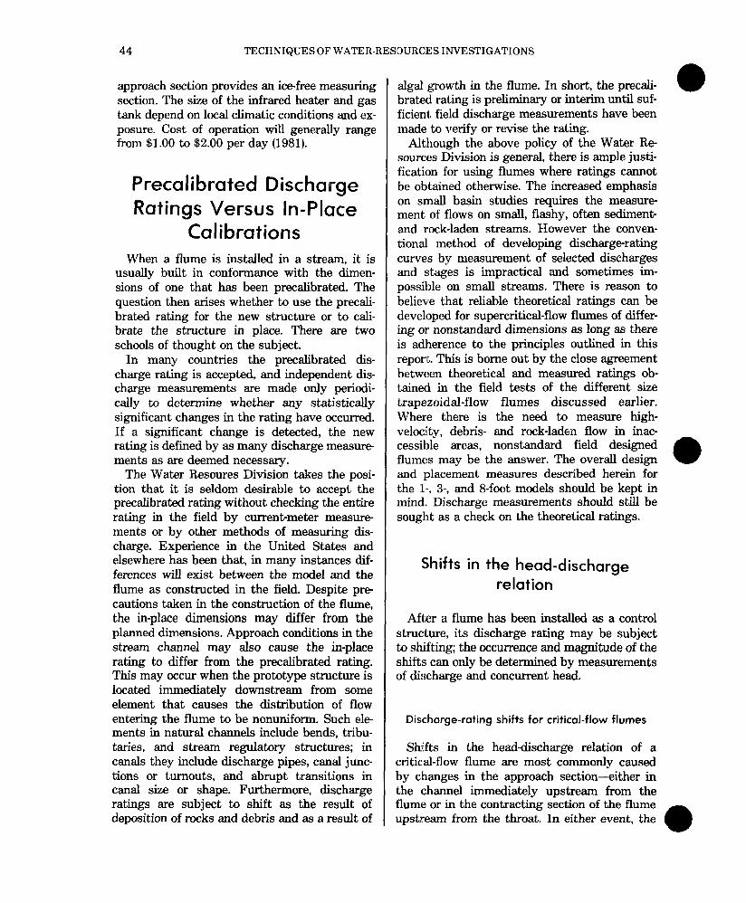
The rocks and debris that are commonly deposited in the level approach reach of a supercritical-flow flume usually have little ef- fect on the head-discharge relation. However, when the deposition is heavy and unsymmetri- cal, as in figure 37 when debris has accumulated almost entirely on the left side of the approach reach, the head-discharge relation for flow in the throat will be affected. Figure 37 shows how the flow pattern in the throat reach has been distorted. The head on the left side of the throat reach is significantly higher than that on the right side; the head recorded depends on the location of the pipe intake or bubble orifice in the head-measurement cross section.
Deposition at the head of the supercritical- flow reach of the flume, even when symmetrical,
FIGURE 37.-Effect of unsymmetrical deposition in flume approach on flow in the throat.
may shift the head-discharge relation to the left by raising the elevation of critical depth at the head of the reach. It will be recalled that the measured head for a given discharge is a func- tion of both the elevation of critical depth up- stream and the geometry of the flume between the critical-depth cross section and the head- measurement section. The farther downstream the measurement section is from the critical- depth cross section, the smaller the influence of changes in critical-depth elevation. Although the actual shifts in head that may occur at the measurement section will usually be small, they can be highly significant because of the sen- sitivity of the headdischarge relation of super- critical flow.
Large rocks driven by high-velocity flow through the supercritical-flow reaches of the flume may erode the walls and floor of those reaches. The resulting increase in roughness and decrease in elevation of the concrete in those reaches may cause shifts in the discharge relation. The two effects tend to be compen- sating; an increase in roughness will shift the discharge rating to the left, and a decrease in elevation of the concrete surface will shift the discharge rating to the right. However, the lat- ter effect usually predominates.
46 TECHNIQUES OF WATER-RESOURCES INVESTIGATIONS
Summary
This chapter discusses the theory, design, and application of various types of flumes for the measurement of open channel flow. Emphasis is placed on the Parshall and supercritical-flow trapezoidal type flumes.
Complete design and discharge-rating infor- mation on Parshall flumes from l-inch to 50-feet is provided for both freeflow and submerged operating conditions. Criteria and procedures for selecting and installing Parshall flumes are provided.
In the case of the supercritical-flow trapezoi- dal flume, three sizes are discussed, based on field tests by the authors. Field discharge rat- ings and theoretical ratings for the l-, 3-, and ES-foot sizes are presented and shown to be in close agreement. Criteria and procedures for the design, selection, fitting, construction, and operation of the supercritical-flow trapezoidal flumes are provided.
References
Bermel, K. J., 1950, Hydraulic influence of modifications to the San Dimas critical depth measuring flume: Amer- ican Geophysical Union, Transcript, v. 31, no. 5, p. 763-768.
Chamberhn, A. R., 1957, Preliminary model tests of a flume for measuring discharge of steep ephemeral streams: Colorado Agricultural and Mechanical College, Rocky Mountain Forest and Range Experimental Station CER57ARC12,28 p.
Chow, V. T., 1959, Open-channel hydraulics: New York, McGraw-Hill, 680 p.
Cone, V. M., 1917, The Venturi flume: Journal of Agricultural Research, v. 9, no. 4, April 23.14 p.
Davis, Sydney, 1963, Unification of Parshall flume data: American Society of Civil Engineers, Paper 3511, Tran- script, v. 128, pt. 3, p. 339-421.
Dodge, R. A., Jr., 1963, Discussion of unification of Par-shall flume data, by Davis, Sydney: American Society of Civil Engineers, Paper 3511, Transcript, v. 128, pt. 3.
Parshall, R. L., 1926, The improved Venturi flume: American Society of Civil Engineers, Transactions, v. ,59, p. 841-851.
-9 1953, Parshall flumes of large size: Colorado Agricultural Experimental Station Bulletin 426A, 40 p.
Robinson, A. R., 1957, Parshall measuring flumes of small sizes: Colorado Agricultural and Mechanical College, Agticultural Experimental Station, Bulletin 61,12 p.
-3 1959, Report on trapezoidal measuring flumes for determining discharge in steep ephemeral streams: Col- orado Agricultural and Mechanical College, Rocky M~ountain Experimental Station, CER59AAR1.13 p.
U.S. Agricultural Research Service, 1962, Field manual for research in agricultural hydrology: U.S. Department of Agriculture, Handbook 724,215 p.
Wilm, H. G., Cotton, John S., and Storey, H. C., 1938, M,easurement of debris-laden stream flow with critical- depth flumes: American Society of Civil Engineers, Transcript, v. 103, p. 1237-1253.