Embed Size (px)
Citation preview
Use of DSC and DMA Techniques to Help Investigate a Material Anomalyfor PTFE Used in Processing a Piston Cup for the Urine Processor Assembly (UPA)
on International Space Station (ISS)
Doug WingardNASA/MSFC Mail Code EM10
Marshall Space Flight Center, Alabama 35812 USA
ABSTRACT
Human urine and flush water are eventually converted into drinking water with the Urine Processor Assembly (UPA) aboard the International Space Station (ISS). This conversion is made possible through the Distillation Assembly (DA) of the UPA. One component of the DA is a molded circular piston cup made of virgin polytetrafluoroethylene (PTFE). The piston cup is assembled to a titanium component using eight fasteners and washers. Molded PTFE produced for spare piston cups in the first quarter of 2010 was different in appearance and texture, and softer than material molded for previous cups. For the suspect newer PTFE material, cup fasteners were tightened to only one-half the required torque value, yet the washers embedded almost halfway into the material.
The molded PTFE used in the DA piston cup should be Type II, based on AMS 3667D and ASTM D4894 specifications. The properties of molded PTFE are considerably different between Type I and II materials. Engineers working with the DA thought that if Type I PTFE was molded by mistake instead of Type II material, that could have resulted in the anomalous material properties. Typically, the vendor molds flat sheet PTFE from the same material lot used to mold the piston cups, and tensile testing as part of quality control should verify that the PTFE is Type II material. However, for this discrepant lot of material, such tensile data was not available. Differential scanning calorimetry (DSC) and dynamic mechanical analysis (DMA) were two of the testing techniques used at the NASA/Marshall Space Flight Center (MSFC) to investigate the anomaly for the PTFE material. Other techniques used on PTFE specimens were: Shore D hardness testing, tensile testing on dog bone specimens and a qualitative estimation of porosity by optical and scanning electron microscopy.
INTRODUCTION
Background for Use of UPA and DA on International Space Station (ISS)
The regenerative Environmental Control and Life Support Systems (ECLSS) for the International Space Station (ISS) includes the Urine Processor Assembly (UPA). The UPA is designed to process an average load of 9 kg/day of wastewater (consisting of human urine and flush water) into drinking water. The urine is pretreated with sulfuric acid and chromium trioxide to control microbial growth and conversion of urea to ammonia. The UPA is designed to recover a minimum of 85% of the water content from pretreated urine. The heart of the UPA is the Distillation Assembly (DA), which consists of a rotating centrifuge where the waste urine stream is evaporated at low pressure and condensed on the opposite side of the surface (1).
https://ntrs.nasa.gov/search.jsp?R=20100035689 2018-05-10T03:02:58+00:00Z
EXPERIMENTAL
Materials Used
For testing, the Materials Test Branch/EM10 at the Marshall Space Flight Center (MSFC) received the following materials of molded PTFE for testing:
• One molded piston cup made from the anomalous (new) material. A molded piston cup made from the good, nominal (old) material was not available for testing.
• Sections of flat molded sheet (~0.5 in. thick) for both the new and old material.
Instruments and Testing Techniques Used
Differential Scanning Calorimeter (DSC)
In EM10, the TA Instruments 2920 Differential Scanning Calorimeter (DSC) was used in the both the standard and modulated modes. In the standard mode, each PTFE sample was given a heat-cool-heat sequence: (a) heating from 200 to 380°C at 10°C/min., (b) cool from 380 to 200°C at 10°C/min., and (c) re-heat from 200 to 380°C at 10°C/min. From the initial heating scan at 10°C/min. for each PTFE sample, modulated DSC parameters were determined based on the temperature width of the melting peak transition at one-half peak height. In the modulated mode, each sample was tested with the following conditions:
• New PTFE material: Heat from 200 to 380°C at an underlying heating rate of 1.8°C/min., and modulate ± 0.29°C every 60 sec.
• Old PTFE material: Heat from 200 to 380°C at an underlying heating rate of 1.0°C/min., and modulate ± 0.16°C every 60 sec.
For preparing each DSC sample, material was shaved from the molded PTFE sheet or cup with a utility knife and cut into very small pieces. The small pieces were placed over most of the surface area of the bottom of a standard aluminum DSC sample pan. Each sample, pan and matching lid was mechanically crimped to give a non-hermetic seal. Each DSC sample of PTFE weighed 8.2-13.1 mg. Each sample was heated in the DSC with a purge of a steady flow of argon gas.
Dynamic Mechanical Analyzer (DMA)
In EM10, the TA Instruments 2980 Dynamic Mechanical Analyzer (DMA) was used with the 50 mm length three-point bending clamp. The circular molded PTFE piston cup with the anomalous properties (new material) was cut into eight sections. For three of these sections, an approximate rectangular sample was cut for DMA testing. Each sample was cut so that the thickness became the width, and the width became the thickness. Two of these cut piston cup sections are shown in Fig. 1. Since a molded piston cup was not available for the old (good, nominal) material, rectangular DMA samples were cut from 0.5 in. thick flat sheet in the same way they were cut from the piston cup. For these samples, the average width and thickness were 9.496 mm and 6.665 mm, respectively. The average length-to-thickness ratio was 7.50, which is less than the desired minimum of 10.0.
The ~ 0.5 in. thick flat sheet material for both new and old PTFE was machined (milled) down on one side to about 0.16 in. thick so that tensile dog bone specimens could be cut out and tested. From this thinner scrap flat sheet material, DMA samples were cut about 2.25 in. length x 0.5 in. width x 0.16 in. thickness. These samples were also tested with the 50 mm length three-point bending clamp. For these samples, the average width and thickness were 12.859 mm and 3.943 mm, respectively. The average length-to-thickness ratio was a more desirable 12.68.
For three-point bending, each sample was heated from 0 to 175°C at 3°C/min. at an amplitude of 15-20 µm, frequency of 1 Hz, and an initial static force of 0.1 N. Slight cooling for each sample was provided by liquid nitrogen in a Gas Cooling Accessory (GCA) attached to the DMA. Argon gas from an outside tank was provided at ~ 65 psi to make the DMA drive shaft float and to provide the sample atmosphere.
Tensile Testing on Dog bone Specimens of PTFE
As mentioned earlier, ~ 0.5 in. thick flat sheet of both new and old PTFE was machined (milled) down on one side to achieve a desired thickness of about 0.16 in. A steel die with a size of a Type IV tensile dog bone specimen was used to cut/stamp out 6-7 specimens of new and old machined flat sheet with the aid of a mechanical hand press. The Type IV specimen, with a nominal maximum width of 0.75 in., minimum width of 0.25 in. and overall length of 4.5 in., was cut according to the specifications in ASTM D 638 (2). Each sample was tested at room temperature on an Instron TS-25 tensile testing machine to determine: (a) tensile stress at maximum load, (b) percent elongation, and (c) modulus of elasticity (Young’s modulus). Modulus data was obtained from the initial stress/strain slope for each sample with the aid of a video extensometer. A load cell of 1100 pounds (force) was used for the testing, and each sample was pulled at a crosshead speed of 0.2 in./min. until failure. Approximately 10 pounds (force) was placed on each sample as a pre-load before it was pulled to failure.
Shore D Hardness Testing
The Newage Exacta Hardness Tester (Model EX-200T), a digital bench top unit, was used in this work. Hardness testing was performed on samples of new and old PTFE described in the Experimental (Materials Used) section as well as on scrap samples of thinner material remaining from tensile testing. The Shore D test head with a sharp tip was used for each sample, and the standard macro-hardness indenter tip length of 2.5 mm was used to strike and indent the sample surface. Each hardness measurement was recorded three seconds after the tip struck and indented the sample surface. The hardness tester was calibrated with the sharp Shore D tip allowed to travel into a small hole in a stainless steel block. The calibration was performed at 0.0 and 100.0 on the Shore D scale so that the readings were within ± 0.1 durometer units of the target values.
For each PTFE sample, ten (10) hardness measurements were made, and an average hardness and standard deviation were reported. Each flat PTFE sample tested exceeded the required minimum thickness of 6.0 mm (0.24 in.) for a Shore D durometer, based on ASTM D2240 (3). When necessary, two layers of flat sheet were built up to exceed the minimum thickness, but such hardness data is usually not as reliable as for a single larger thickness.
Porosity Estimation in PTFE Specimens by Optical and Scanning Electron Microscopy
The Failure Analysis & Metallurgy Branch/EM31 at MSFC used optical and scanning electron microscopy (SEM) to make a qualitative estimation of porosity in samples of new and old PTFE (4). The porosity estimation was made on samples of new and old PTFE described in the Experimental section, as well as on scrap samples of thinner material remaining from tensile testing. Each sample was cut through the cross-section and vacuum impregnated with an epoxy resin to allow resin cure. Afterward, the sample cross-section was polished to prepare for microscopy.
RESULTS AND DISCUSSION
DSC Data
DSC data on PTFE samples is summarized in Table 1. One sample each from the new material piston cup and old flat sheet were given a standard heating “heat-cool-reheat” sequence, with each segment at 10°C/min. For the old, nominal material, there was little difference in the heat of fusion or peak melting temperature between the first and second heating scans. For the new material, the heat of fusion decreased almost one-half and the melting temperature decreased by almost 14°C between the first and second heating scan. In fact, the second heating scans yielded almost identical results for both the new and old materials.
Modulated DSC tests were also performed on the new and old PTFE materials. For new material scraped from the piston cup and flat sheet, the data was very similar. The peak melting temperature averaged 10.6°C higher for the new material compared to old material. The estimated percent crystallinity averaged as much as 86% higher for the new material compared to old material. Percent crystallinity was determined for each sample by dividing heat of fusion by that of 100% crystalline PTFE—82 J/g (5). DuPont indicates that Teflon® PTFE typically has crystallinity of 46-55% for thin films to parts thicker than 0.25 inches (6). For old, nominal PTFE, percent crystallinity was slightly less than the DuPont range, but for new PTFE it was considerably higher.
From modulated DSC tests, Figs. 2 and 3 show total heat flow vs. temperature for multiple samples of new and old PTFE cut from flat sheet material. Figure 3 shows a typical single sharp melting peak for the old material. However, Fig. 2 shows the expected sharp melting peak, as well as a smaller “shoulder” peak near 330°C. Some researchers have attributed such double melting peaks in PTFE mostly to folded molecular ribbons or granular particles (7). They claim that the double peaks indicate two different crystalline states in the material and an increased melting temperature of virgin PTFE at molecular weights above 1 x 10⁶.
DMA Data
DMA data on PTFE samples is summarized in Table 2, and all rectangular samples were tested with a 50 mm length three-point bending clamp. Samples of new material from the piston cup were cut such that the original thickness became the width, and the width became the thickness. As a comparison, samples of old material from flat sheet were cut the same way. For these samples, the storage modulus at room temperature (23°C) averaged 31.5% higher for the new material compared to old material. Flat sheet rectangular samples were also cut in plane with the through-thickness for scrap material left from making tensile specimens (~ 0.16 in. thick). For these samples, the storage modulus at 23°C averaged 36.1% higher for the new material compared to old material.
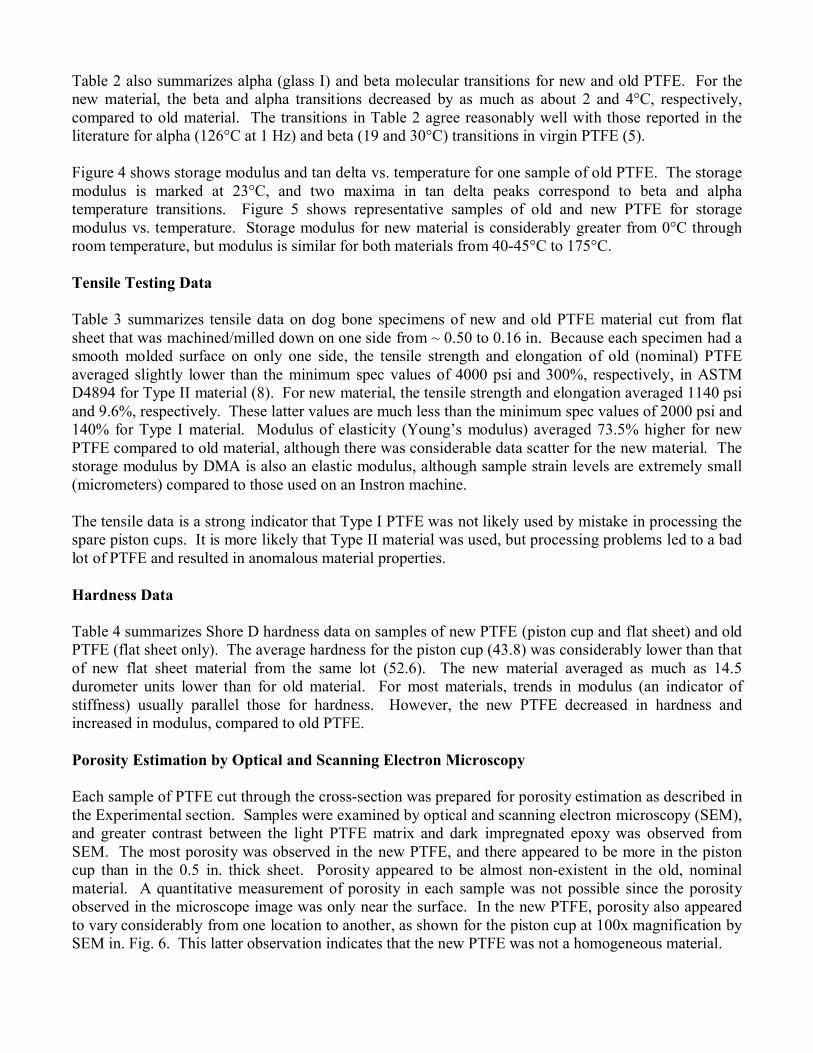
Table 2 also summarizes alpha (glass I) and beta molecular transitions for new and old PTFE. For the new material, the beta and alpha transitions decreased by as much as about 2 and 4°C, respectively, compared to old material. The transitions in Table 2 agree reasonably well with those reported in the literature for alpha (126°C at 1 Hz) and beta (19 and 30°C) transitions in virgin PTFE (5).
Figure 4 shows storage modulus and tan delta vs. temperature for one sample of old PTFE. The storage modulus is marked at 23°C, and two maxima in tan delta peaks correspond to beta and alpha temperature transitions. Figure 5 shows representative samples of old and new PTFE for storage modulus vs. temperature. Storage modulus for new material is considerably greater from 0°C through room temperature, but modulus is similar for both materials from 40-45°C to 175°C.
Tensile Testing Data
Table 3 summarizes tensile data on dog bone specimens of new and old PTFE material cut from flat sheet that was machined/milled down on one side from ~ 0.50 to 0.16 in. Because each specimen had a smooth molded surface on only one side, the tensile strength and elongation of old (nominal) PTFE averaged slightly lower than the minimum spec values of 4000 psi and 300%, respectively, in ASTM D4894 for Type II material (8). For new material, the tensile strength and elongation averaged 1140 psi and 9.6%, respectively. These latter values are much less than the minimum spec values of 2000 psi and 140% for Type I material. Modulus of elasticity (Young’s modulus) averaged 73.5% higher for new PTFE compared to old material, although there was considerable data scatter for the new material. The storage modulus by DMA is also an elastic modulus, although sample strain levels are extremely small (micrometers) compared to those used on an Instron machine.
The tensile data is a strong indicator that Type I PTFE was not likely used by mistake in processing the spare piston cups. It is more likely that Type II material was used, but processing problems led to a bad lot of PTFE and resulted in anomalous material properties.
Hardness Data
Table 4 summarizes Shore D hardness data on samples of new PTFE (piston cup and flat sheet) and old PTFE (flat sheet only). The average hardness for the piston cup (43.8) was considerably lower than that of new flat sheet material from the same lot (52.6). The new material averaged as much as 14.5 durometer units lower than for old material. For most materials, trends in modulus (an indicator of stiffness) usually parallel those for hardness. However, the new PTFE decreased in hardness and increased in modulus, compared to old PTFE.
Porosity Estimation by Optical and Scanning Electron Microscopy
Each sample of PTFE cut through the cross-section was prepared for porosity estimation as described in the Experimental section. Samples were examined by optical and scanning electron microscopy (SEM), and greater contrast between the light PTFE matrix and dark impregnated epoxy was observed from SEM. The most porosity was observed in the new PTFE, and there appeared to be more in the piston cup than in the 0.5 in. thick sheet. Porosity appeared to be almost non-existent in the old, nominal material. A quantitative measurement of porosity in each sample was not possible since the porosity observed in the microscope image was only near the surface. In the new PTFE, porosity also appeared to vary considerably from one location to another, as shown for the piston cup at 100x magnification by SEM in. Fig. 6. This latter observation indicates that the new PTFE was not a homogeneous material.
SUMMARY AND CONCLUSIONS
A molded circular piston cup made of virgin polytetrafluoroethylene (PTFE) is a component of the Distillation Assembly (DA) that is the heart of the Urine Processor Assembly (UPA) used to convert human urine and flush water into drinking water on International Space Station (ISS). Spare piston cups molded in early 2010 were different in appearance and texture, and softer, than previous cups. Type II PTFE is normally used to mold the piston cups, and it was suspected that Type I material might have used by mistake. A number of testing techniques were used at the NASA/Marshall Space Flight Center (MSFC) to investigate this material anomaly. These were the major findings of this work:
• Differential scanning calorimeter (DSC) data showed that estimated percent crystallinity averaged as much as 86% higher for the suspect (new) PTFE than for the nominal (old) material. The DSC melting region of the new PTFE showed double peaks instead of one sharp peak. Researchers have attributed the double peaks to different crystalline states in virgin PTFE.
• Dynamic mechanical analyzer (DMA) data showed that the storage (elastic) modulus at room temperature (23°C) averaged as much as 36% higher for the new PTFE than for old material. Modulus is an indicator of stiffness in a material.
• Tensile testing was performed at room temperature on dog bone specimens of new and old PTFE. The old material had tensile strength and percent elongation very similar to those required by the ASTM D4894 spec for Type II material. However, tensile properties for the new material were much lower than those required for Type I material. Elastic modulus was as much as 73.5% higher for new PTFE compared to old material. This data indicated that Type I material was not likely used by mistake, but that problems with processing/molding yielded a bad lot of Type II material.
• Shore D hardness data showed that the new PTFE averaged as much as 14.5 durometer points lower than for old material. Trends in hardness usually parallel those of modulus for a material. However, hardness decreased and modulus increased for new PTFE compared to old material.
• Several specimens of new and old PTFE were cut through the cross-sections and vacuum impregnated with epoxy. The cured epoxy surface was polished and observed by optical and scanning electron microscopy (SEM). A qualitative estimate of porosity showed that the new PTFE had high porosity, while old PTFE had very little porosity. The amount of porosity also varied considerably in the new PTFE from one location to another, indicating that the new PTFE was not a homogenous material.
ACKNOWLEDGMENTS
The author acknowledges the following co-workers in the Materials Test Branch/EM10 at MSFC: Leonard Alexander machined/milled flat sheet sections of PTFE to the desired thickness so that tensile specimens could be cut out. Enrique Jackson assisted in testing PTFE samples by DMA, as well as in cutting out PTFE tensile specimens. The author also acknowledges Wendell DeWeese and Greg Jerman of the Failure Analysis & Metallurgy Branch/EM31 at MSFC for sample preparation and microscopic analysis of PTFE samples for porosity estimation. Ayman Girgis of Jacobs Engineering at MSFC performed testing and data analysis for PTFE tensile specimens.
REFERENCES
1. D. Layne Carter, “Status of the Regenerative ECLSS Water Recovery System,” NASA, Marshall Space Flight Center, Report 2009-01-2352, http://ntrs.nasa.gov/archive/nasa/casi.ntrs.nasa.gov/20090033097_2009032866.pdf
2. ASTM D638-08, “Standard Test Method for Tensile Properties of Plastics,” published May 2008.
3. ASTM D2240-05, “Standard Test Method for Rubber Property—Durometer Hardness,” published April 2010.
4. G. Jerman, “ECLSS Distillation Assembly Teflon Piston Cup Analysis,” Failure Analysis & Metallurgy Branch/EM31, NASA, Marshall Space Flight Center, 05/24/2010.
5. Polymer Handbook, Third Edition, J. Brandrup and E. H. Immergut, Editors, V/39, 41, Wiley & Sons, New York (1989).
6. DuPont™ Teflon PTFE fluoropolymer resin Properties Handbook, printed 1/04 in U.S.A.
7. T. Suwa, et al., J. Polym. Sci.: Polym. Phys. Ed., 13 (11), 2183-2194 (1975).
8. ASTM D4894-07, “Standard Specification for Polytetrafluoroethylene (PTFE) Granular Molding and Ram Extrusion Materials,” published October 2007.
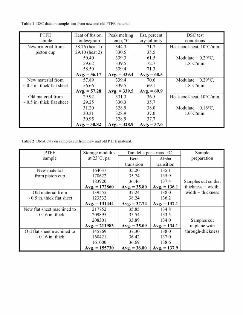
Table 1 DSC data on samples cut from new and old PTFE material.
PTFE sample
Heat of fusion,Joules/gram
Peak meltingtemp, °C
Est. percentcrystallinity
DSC testconditions
New material from piston cup
58.76 (heat 1)29.10 (heat 2)
344.3330.5
71.735.5
Heat-cool-heat, 10°C/min.
50.4059.6258.50
Avg. = 56.17
339.3339.5339.4
Avg. = 339.4
61.572.771.3
Avg. = 68.5
Modulate ± 0.29°C, 1.8°C/min.
New material from~ 0.5 in. thick flat sheet
57.8956.66
Avg. = 57.28
339.4339.5
Avg. = 339.5
70.669.1
Avg. = 69.9
Modulate ± 0.29°C, 1.8°C/min.
Old material from~ 0.5 in. thick flat sheet
29.9229.25
331.3330.3
36.535.7
Heat-cool-heat, 10°C/min.
31.2030.3130.95
Avg. = 30.82
328.9328.9328.9
Avg. = 328.9
38.037.037.7
Avg. = 37.6
Modulate ± 0.16°C, 1.0°C/min.
Table 2 DMA data on samples cut from new and old PTFE material.
PTFEsample
Storage modulusat 23°C, psi
Tan delta peak max, °C SamplepreparationBeta
transitionAlpha
transitionNew material
from piston cup164037170622183920
Avg. = 172860
35.2035.7436.46
Avg. = 35.80
135.1135.9137.4
Avg. = 136.1Samples cut so thatthickness = width,width = thicknessOld material from
~ 0.5 in. thick flat sheet139555123332
Avg. = 131444
37.2438.24
Avg. = 37.74
138.0136.2
Avg. = 137.1New flat sheet machined to
~ 0.16 in. thick217752209895208301
Avg. = 211983
35.8535.5433.89
Avg. = 35.09
134.8133.5134.0
Avg. = 134.1Samples cutin plane with
through-thicknessOld flat sheet machined to~ 0.16 in. thick
145769160421161000
Avg. = 155730
37.3036.4236.69
Avg. = 36.80
138.0137.0138.6
Avg. = 137.9
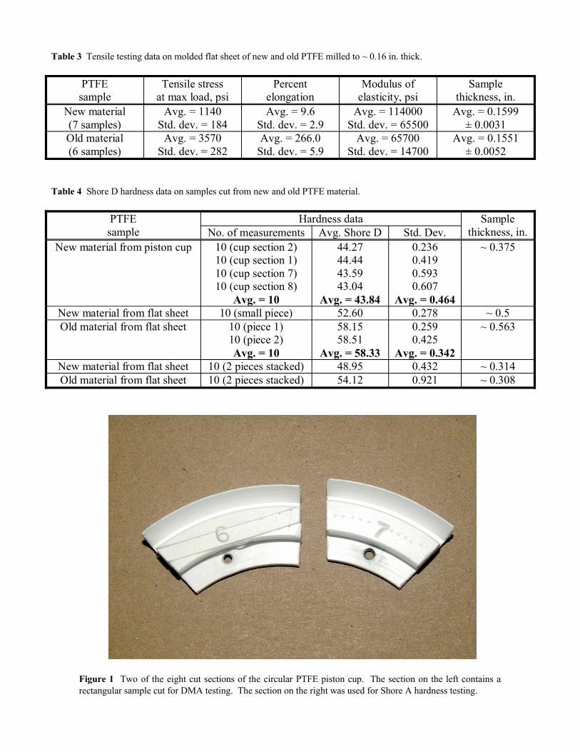
Table 3 Tensile testing data on molded flat sheet of new and old PTFE milled to ~ 0.16 in. thick.
PTFEsample
Tensile stressat max load, psi
Percentelongation
Modulus of elasticity, psi
Samplethickness, in.
New material(7 samples)
Avg. = 1140Std. dev. = 184
Avg. = 9.6Std. dev. = 2.9
Avg. = 114000Std. dev. = 65500
Avg. = 0.1599 ± 0.0031
Old material(6 samples)
Avg. = 3570Std. dev. = 282
Avg. = 266.0Std. dev. = 5.9
Avg. = 65700Std. dev. = 14700
Avg. = 0.1551± 0.0052
Table 4 Shore D hardness data on samples cut from new and old PTFE material.
PTFEsample
Hardness data Samplethickness, in.No. of measurements Avg. Shore D Std. Dev.
New material from piston cup 10 (cup section 2)10 (cup section 1)10 (cup section 7)10 (cup section 8)
Avg. = 10
44.2744.4443.5943.04
Avg. = 43.84
0.2360.4190.5930.607
Avg. = 0.464
~ 0.375
New material from flat sheet 10 (small piece) 52.60 0.278 ~ 0.5Old material from flat sheet 10 (piece 1)
10 (piece 2)Avg. = 10
58.1558.51
Avg. = 58.33
0.2590.425
Avg. = 0.342
~ 0.563
New material from flat sheet 10 (2 pieces stacked) 48.95 0.432 ~ 0.314Old material from flat sheet 10 (2 pieces stacked) 54.12 0.921 ~ 0.308
Figure 1 Two of the eight cut sections of the circular PTFE piston cup. The section on the left contains a rectangular sample cut for DMA testing. The section on the right was used for Shore A hardness testing.
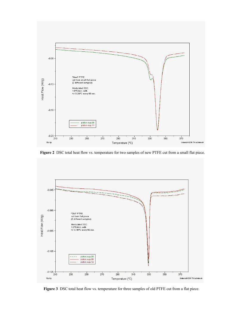
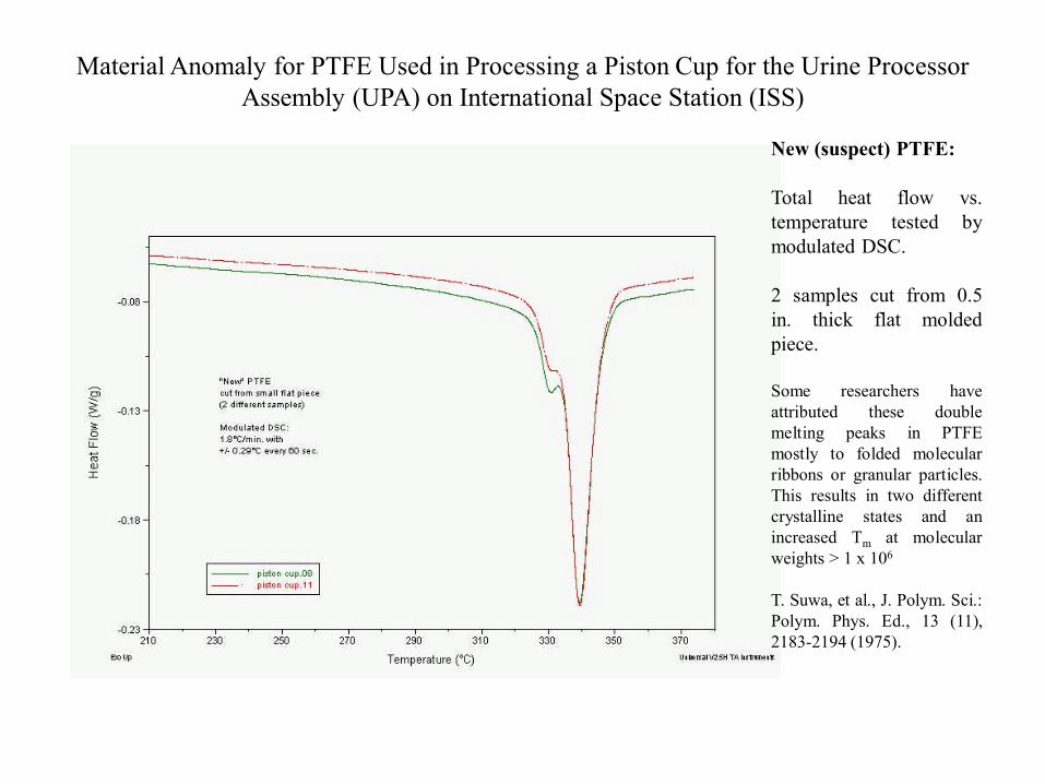
Figure 2 DSC total heat flow vs. temperature for two samples of new PTFE cut from a small flat piece.
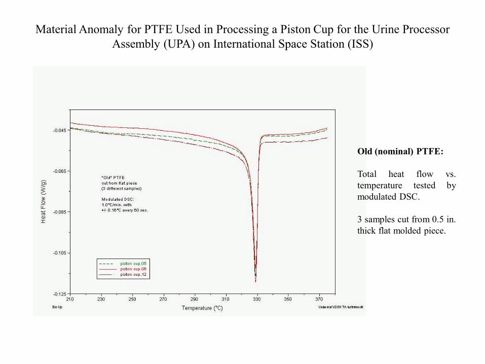
Figure 3 DSC total heat flow vs. temperature for three samples of old PTFE cut from a flat piece.
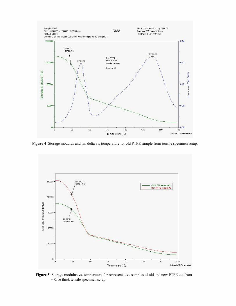
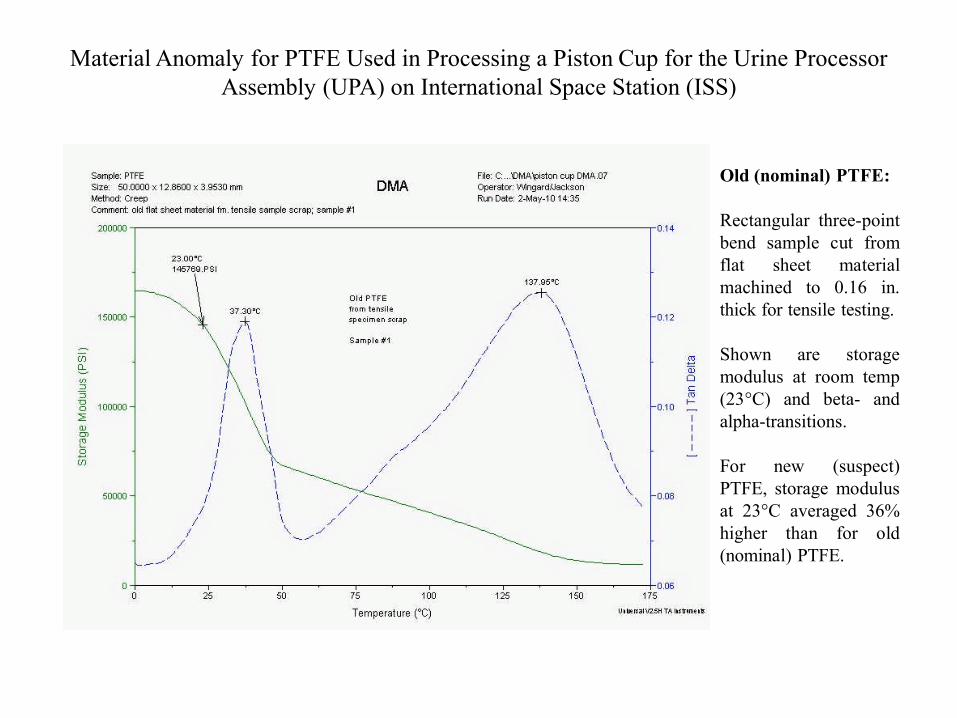
Figure 4 Storage modulus and tan delta vs. temperature for old PTFE sample from tensile specimen scrap.
Figure 5 Storage modulus vs. temperature for representative samples of old and new PTFE cut from~ 0.16 thick tensile specimen scrap.
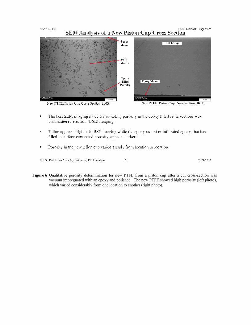
Figure 6 Qualitative porosity determination for new PTFE from a piston cup after a cut cross-section was vacuum impregnated with an epoxy and polished. The new PTFE showed high porosity (left photo), which varied considerably from one location to another (right photo).
Use of DSC and DMA Techniques to Help Investigate a Material Anomaly for PTFE Used in Processing a Piston Cup for the Urine Processor Assembly (UPA) on International Space Station (ISS)
Doug WingardNASA/Marshall Space Flight Center (MSFC) USA
Materials Test Branch / [email protected]
Material Anomaly for PTFE Used in Processing a Piston Cup for the Urine Processor Assembly (UPA) on International Space Station (ISS)
• The Distillation Assembly (DA) is the heart of the Urine Processor Assembly(UPA) on Space Station for converting urine and flush water into drinking water.
• One component of the DA is a molded circular piston cup made of virgin PTFE.
• In early 2010, molded PTFE produced for spare piston cups was different inappearance, texture and hardness—not acceptable for assembling to a titaniumcomponent.
• Molded PTFE used should be Type II (AMS 3667D / ASTM D4894), but UPAengineers thought perhaps Type I material was used by mistake.
• Testing was performed at NASA/MSFC to investigate this anomaly:DSC, DMA, Shore D hardness, tensile testing and qualitative porosity testing.
Material Anomaly for PTFE Used in Processing a Piston Cup for the Urine Processor Assembly (UPA) on International Space Station (ISS)
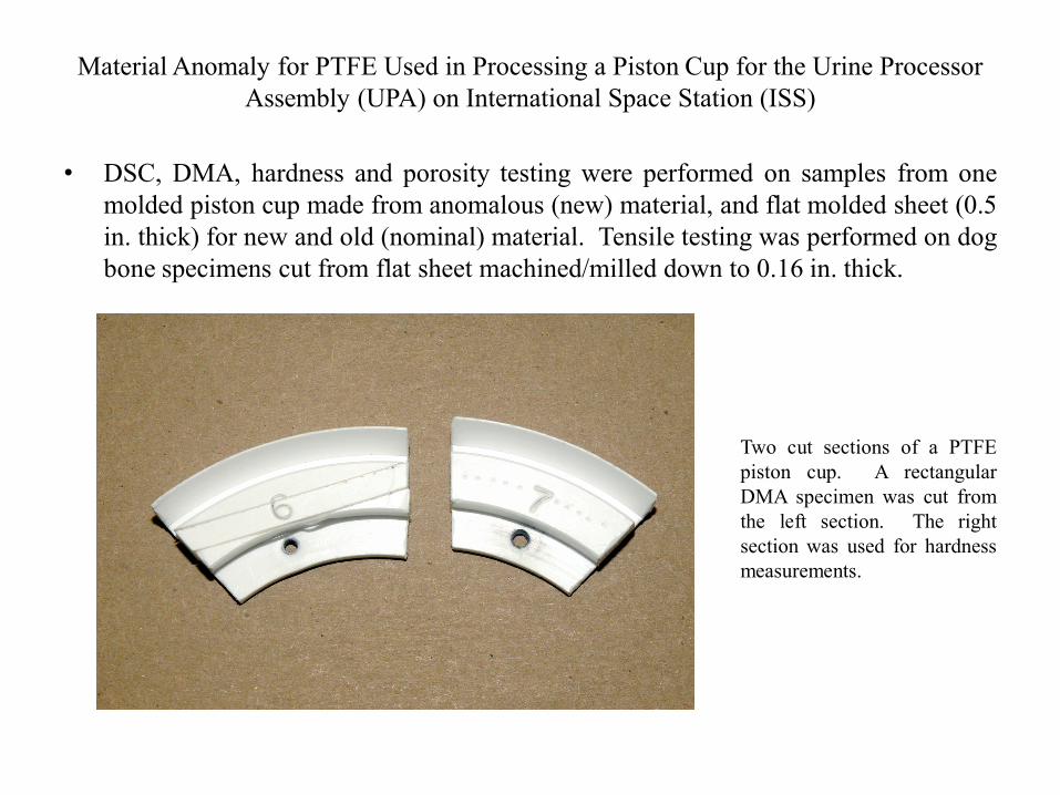
• DSC, DMA, hardness and porosity testing were performed on samples from onemolded piston cup made from anomalous (new) material, and flat molded sheet (0.5in. thick) for new and old (nominal) material. Tensile testing was performed on dogbone specimens cut from flat sheet machined/milled down to 0.16 in. thick.
Two cut sections of a PTFEpiston cup. A rectangularDMA specimen was cut fromthe left section. The rightsection was used for hardnessmeasurements.
Material Anomaly for PTFE Used in Processing a Piston Cup for the Urine Processor Assembly (UPA) on International Space Station (ISS)
Material Anomaly for PTFE Used in Processing a Piston Cup for the Urine Processor Assembly (UPA) on International Space Station (ISS)
Old (nominal) PTFE:
Total heat flow vs.temperature tested bymodulated DSC.
3 samples cut from 0.5 in.thick flat molded piece.
Material Anomaly for PTFE Used in Processing a Piston Cup for the Urine Processor Assembly (UPA) on International Space Station (ISS)
New (suspect) PTFE:
Total heat flow vs.temperature tested bymodulated DSC.
2 samples cut from 0.5in. thick flat moldedpiece.
Some researchers haveattributed these doublemelting peaks in PTFEmostly to folded molecularribbons or granular particles.This results in two differentcrystalline states and anincreased Tm at molecularweights > 1 x 10⁶
T. Suwa, et al., J. Polym. Sci.:Polym. Phys. Ed., 13 (11),2183-2194 (1975).
Material Anomaly for PTFE Used in Processing a Piston Cup for the Urine Processor Assembly (UPA) on International Space Station (ISS)
Material Anomaly for PTFE Used in Processing a Piston Cup for the Urine Processor Assembly (UPA) on International Space Station (ISS)
Old (nominal) PTFE:
Rectangular three-pointbend sample cut fromflat sheet materialmachined to 0.16 in.thick for tensile testing.
Shown are storagemodulus at room temp(23°C) and beta- andalpha-transitions.
For new (suspect)PTFE, storage modulusat 23°C averaged 36%higher than for old(nominal) PTFE.
Material Anomaly for PTFE Used in Processing a Piston Cup for the Urine Processor Assembly (UPA) on International Space Station (ISS)
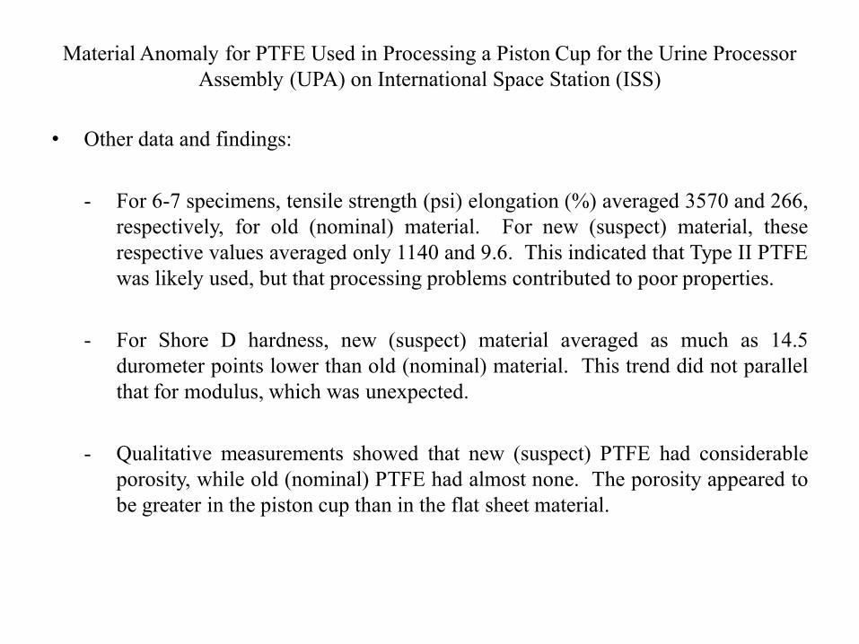
• Other data and findings:
- For 6-7 specimens, tensile strength (psi) elongation (%) averaged 3570 and 266,respectively, for old (nominal) material. For new (suspect) material, theserespective values averaged only 1140 and 9.6. This indicated that Type II PTFEwas likely used, but that processing problems contributed to poor properties.
- For Shore D hardness, new (suspect) material averaged as much as 14.5durometer points lower than old (nominal) material. This trend did not parallelthat for modulus, which was unexpected.
- Qualitative measurements showed that new (suspect) PTFE had considerableporosity, while old (nominal) PTFE had almost none. The porosity appeared tobe greater in the piston cup than in the flat sheet material.
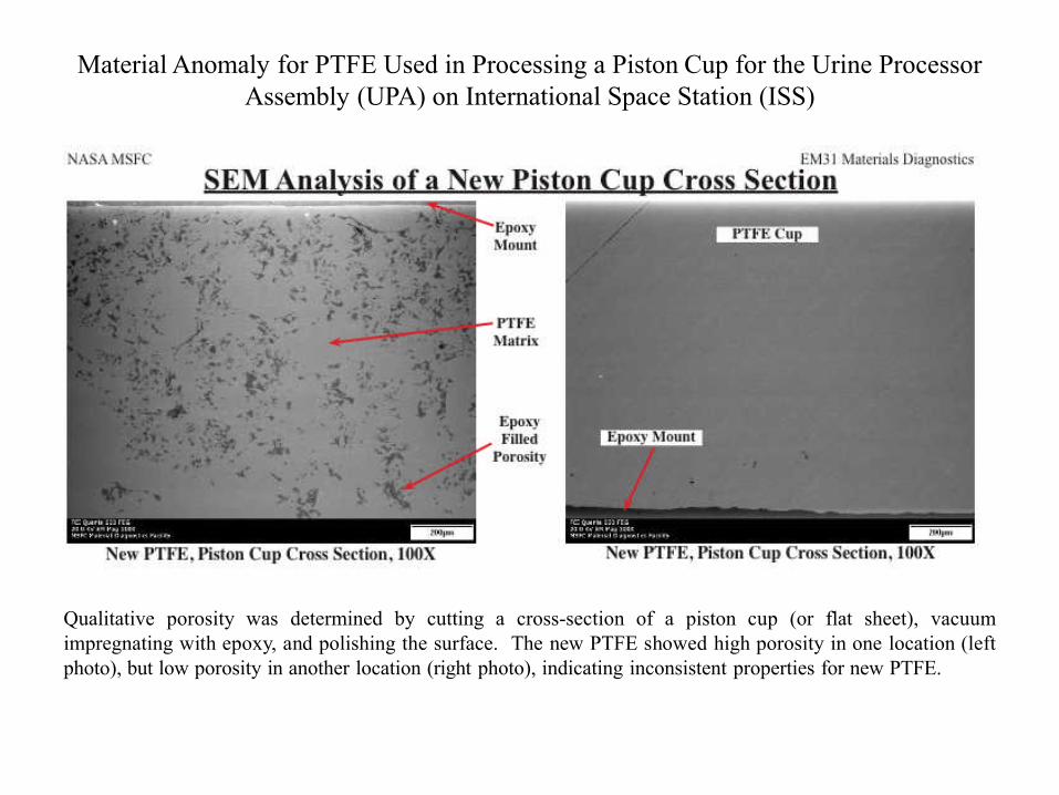
Material Anomaly for PTFE Used in Processing a Piston Cup for the Urine Processor Assembly (UPA) on International Space Station (ISS)
Qualitative porosity was determined by cutting a cross-section of a piston cup (or flat sheet), vacuumimpregnating with epoxy, and polishing the surface. The new PTFE showed high porosity in one location (leftphoto), but low porosity in another location (right photo), indicating inconsistent properties for new PTFE.
Material Anomaly for PTFE Used in Processing a Piston Cup for the Urine Processor Assembly (UPA) on International Space Station (ISS)
• I would like to acknowledge several at MSFC who contributed to this work:
- Leonard Alexander machined/milled thick flat sheets of PTFE to the desiredthickness so that tensile specimens could be cut out.
- Enrique Jackson assisted in cutting out PTFE tensile specimens, and in testingPTFE samples by DMA.
- Wendell DeWeese prepared PTFE samples for microscopy, and Greg Jermanused microscopy to make qualitative estimations of porosity in PTFE samples.
- Ayman Girgis performed testing and data analysis for PTFE tensile specimens.