Embed Size (px)
Citation preview
USE OF BISTATIC RADAR TECHNIQUESTO IMPROVE RESOLUTION IN THEVERTICAL PLANE
This letter shows that the normal limitations on radar per-formance relating to resolution in the vertical plane may beconsiderably reduced in certain instances by the use of bistatictechniques. A particular feature of the technique is that thevertical dimension of the resolution cell is primarily dependenton the transmitted bandwidth, rather than the vertical aerialaperture. The volume of cover over which this improvementin resolution can be maintained is limited to the regionaround the vertical plane containing both the transmitter and
i
There are many radar applications in which it is not possible toachieve the required resolution in the vertical plane, mainlybecause of limitations in the vertical aerial aperture and/orimperfections in the propagating medium. This letter drawsattention to the fact that a bistatic radar (i.e. a radar in whichthe transmitter and receiver are separated by a distance whichmay be comparable with the nominal maximum range) maybe used to obtain a considerable increase in vertical-plane(target-elevation) resolution over a restricted volume of cover.A useful feature of this proposal is that the magnitude of theresolution cell in elevation over the volume in question is nolonger a function of the vertical aerial aperture, but only ofthe radiated bandwidth (or pulse duration).
Although bistatic radar has been the subject of severalstudies, it has rarely been used in practice, except in theguided-missile field when the receiver is carried on themissile. The main limitation of bistatic radar is that its usefulcoverage is limited to a vertical-fence-like volume in theregion of the vertical plane containing the transmitter andreceiver, and this tends to restrict its application.1
ft
transmitterR
recei ver
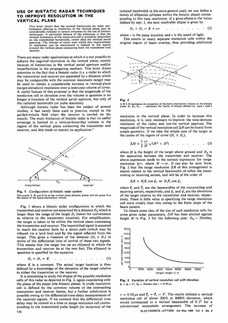
Fig. 1 Configuration of bistatic radar systemThe points T, R and O lie in the vertical plane (bistatic plane) and the point O isthe centre of the beam-intersection volume
Fig. 1 shows a bistatic radar configuration in which thetransmitter and receiver are separated by a distance Db which islarger than the range of the target D, (taken for convenienceas relative to the transmitter location). For simplification,the target is taken to be within the vertical plane containingthe transmitter and receiver. The transmitted signal is assumedto reach the receiver both by a direct path (which may berelayed via a land line) and by the signal reflected from thetarget. This gives a measure of the distance (£>, + Dr) interms of the differential time of arrival of these two signals.This means that the target lies on an ellipsoid in which thetransmitter and receiver lie at the two foci. The ellipsoid inquestion is specified by the equation
Dt + Dr = K 0)where K is a constant. The actual target location is thendefined by a knowledge of the elevation of the target relativeto either the transmitter or the receiver.
It is interesting to study the shapes of the possible resolutioncells of this radar as depicted in Fig. 2, again considering onlythe plane of the paper (the bistatic plane). A crude resolutioncell is defined by the common volume of the intersectingtransmitter and receiver beams, but a further subdivision ispossible owing to the differential-time-delay measurements ofthe received signals. If we contend that the differential timedelay may be related to a time or range resolution cell corres-ponding to the transmitted pulse length (or reciprocal of the170
radiated bandwidth in the more general case), we can define afamily of ellipsoids (ellipses within the bistatic plane) corres-ponding to this time resolution. If a given ellipse is the locusdefined by eqn. 1, the next resolvable ellipse is given by
r = K+cr (2)
where T is the pulse duration and c is the speed of light.This results in many separate resolution cells within the
original region of beam overlap, thus providing additional
Fig. 2A B C D represents the projection of the beam intersection volums in the bistaticplane. Ei, E2, E3 . . . represents the family of ellipses defined by eqns.l and 2
resolution in the vertical plane. In order to increase thisresolution, it is only necessary to improve the time-domainresolution of the radar, and not the vertical aperture. Themagnitude of the vertical resolution cell AH can be found fromsimple geometry. If we take the simple case of the target inthe centre of the region of cover (Dt ~ Dr),
(3)
where H is the height of the target above ground and Db isthe separation between the transmitter and receiver. Theabove expression tends to the normal expression for rangeresolution ±cr, where i/—>oo. It can also be seen fromFig. 2 that the range resolution AR of this arrangement ismainly related to the vertical beamwidth of either the trans-mitting or receiving aerials, and will be of the order of
AR ~ Dfi, cos «/r, or Dr6r cos t//r
where 6, and 6r are the beamwidths of the transmitting andreceiving aerials, respectively, and iff, and \jjr are the elevationsof the target relative to the transmitter and receiver, respec-tively. There is little value in specifying the range resolutioncell more closely than this, owing to the finite slope of thebeam pattern.
To obtain some idea of the size of such resolution cells forsome given radar parameters, AH has been plotted againstheight H in Fig. 3 for the following case: Db = 20miles,
1600
1400
~- 1200
^ 1000
• | 800
§ 600
§ 400
fe 200
1000 2OOO 3000 4000 5000target height H, ft
6000 7000
Fig. 3 Variation of vertical resolution cell with elevation6r = 6/ = 3°; Db = 20miles and - = 0 0 5 (is
r = 0 05/xs and 6t = 6r = 3°. The results indicate a verticalresolution cell of about 200 ft at 6000ft elevation, whichwould correspond to a vertical beamwidth of 0-2° for aconventional monostatic arrangement. The increase of
ELECTRONICS LETTERS 3rd May 1968 Vol. 4 No. 9
vertical resolution is quite impressive, although limited incover to the bistatic fence. The value of the technique dependson the fact that, in most radar problems, it is easier to reducethe pulse duration than to increase the aerial size. It is worthemphasising that the cell is a true resolution cell and resultsin consequent improvements in signal/distributed-clutterratios.
The approximate dimensions of the resolution cell will notchange drastically provided that the target remains within thevertical bistatic plane containing the transmitter and receiver,and provided that ijj, < 90° and ipr < 90°. A tracking radarmay be considered to possess good height resolution whenlooking vertically upwards; these proposals merely extendthis type of performance over the volume of the bistatic fencecoverage. When the intersection point of the beam boresightsmoves outside this plane, the resolution cell changes shape.This results in a distorted and tilted cell, providing resolutionthat is difficult to utilise.
The fact that the vertical resolution is tied to the radiatedbandwidth would tend to suggest that very high resolutionrequirements would require a pulse-compression or widebandc.w. waveform. However, we can make further use of thefact that there is an additional, though larger, resolution cellassociated with the size of the beam intersection volume, sothat, for an efficient choice of waveform, it is necessary toexclude ambiguity from this volume alone. This approachmay have considerable advantages in terms of both mean-power considerations and convenience of radiated waveform.For example, consider a transmission consisting of a train ofsimple short pulses; it would be quite possible to operate atvery high pulse-repetition frequencies (approaching themegahertz region) without involving ambiguities of targetposition, since the ambiguities associated with the highrepetition rate would correspond to target locations outsidethe beam-intersection volume. A study of the ambiguitydiagram would probably reveal more convenient and efficientwaveforms to take full advantage of this situation.
One potential application of the above improvements inresolution relates to situations in which more than onetracking radar is available with an overlapping area of cover.If two such radars are used in a bistatic role, a marked in-crease in vertical resolution is available for targets which passthrough the bistatic fence. Furthermore, if one or both ofthese radars can also operate in a monostatic role, there willbe an additional monostatic resolution cell. However, it is notpermissible to combine these resolutions directly, althoughoccasions can arise in which one system is superior to the otherfor resolution of a given set of targets.
Several different approaches to the operation of bistaticradars have been discussed in the literature.1 These haveinvolved mechanical beam position, electronic beam scanning,and multiple-beam-forming systems. The necessity of usingeither electronic scanning or multiple-beam forming arisesfrom the fact that such complications are necessary tomaintain the data renewal rate over the entire fence cover.These systems are, in general, quite compatible with theresolution improvements discussed here; e.g. a high data-renewal rate may be achieved using high repetition-ratetransmissions together with slow mechanical beam scanningin the vertical plane.
This work was undertaken while the author was on part-time detachment to RRE, Malvern, from the University ofBirmingham. The author wishes to acknowledge helpfuldiscussions on these topics with his former colleagues in bothorganisations.
This letter is contributed by permission of the Director ofRRE and the copyright controller, HMSO.
D. E. N. DA VIES 25th March 1968
Research DepartmentBritish Railways BoardDerby, England
Reference1 SKOLNICK, M. i.: 'An analysis of bistatic radar', IRE Trans., 1961,
ANE-8, p. 19-27
ELECTRONICS LETTERS 3rd May 1968 Vol. 4 No. 9
PHASE-PLANE TRAJECTORIES FORLINEAR-P.CM.-OSCILLATOR CONTROLSYSTEMS
The existence of more than one operating mode for thesesystems is well known. Phase-plane diagrams are shown tobe useful in deducing the existence and stability of thesemodes as the line delays and initial uncontrolled oscillatorfrequencies are varied. Simple 3-station networks are consideredhere, but the technique may be generalised to larger networks.
The stability of the control system has been deduced1 bymeans of the Laplace transform of the system equations.The final-system frequency fs can also be found from thesetransformed equations. Phase-plane diagrams may be con-structed for the system. The equilibrium points and tra-jectories in these diagrams give much insight into the systembehaviour, including the existence and stability of operatingmodes. This technique is a powerful alternative to the analysisof Saito,2 and can be generalised to include large systems.
The system equations are
=/oi7 = 1
(1)
where
and[ ] 1S t n e Gaussian notation,
ij = #/ ~ 4>i ~\ ^JJt-dti
The term rti arises from the cyclic nature of the phase com-parators.
We will put kjj = kajj, where a{j = 0 or 1 andn
On = - S aui
and we also put dn = 0 and ru = 0.
We defineS,7 and Nu by /Aj = Nu + fs8u (2)
where Nu is an integer and/^ is the final-system frequency.We define the integer
NU (3)
and we find that qu = 0 when <£; = <f>j and S,7 = 0.We now transform eqns. 1 to phase-difference equations by
putting x = B<f>, where B is typically of the form
10
0
01
0
. 0
. 0
. 1
- 1- 1
—1B =
and we define A* and D* by A*.B = B.A and D*.B = B.D.Eqn. 1 becomes
[/ + kD*]x = Bf0 + kA*x- kB[R + fsD]c
where c' = [1, 1 , . . . 1]F r o m eqns. 2 and 3,
Hence
[/ + kD*]x = Bf0 + kA*x - kB[Q + /5A] . (4)
= 0 in the steady state for which 0, = fs,
for a l l / = 1,2,.. ., n.
The matrix A has as elements the variations S,y of the delaysfrom the ideal values of integral multiples of frames.
The matrix Q has as elements the number of times q-tithat the output of the phase comparator has passed throughthe discontinuity owing to variations of phase, line delay, oroscillator natural frequency, after the initial set-up.
In a fully interconnected network, A* = nl. If, in addition,all the delays are equal to d, D* = — dl and B[Ac]= B[(n - l)8c] = 0.
We will first consider the fully connected network with171


![PDR slides.ppt [Read-Only] - Aerospace Engineering · PDR Presentation August 16 th-17 th, 2007 Logan, ... construct and validate a GPS bistatic radar ... Bistatic Radar : Transmitter](https://img.pdfslide.us/doc/110x75/5ae5c1b67f8b9aee078bfaa0/pdr-read-only-aerospace-engineering-presentation-august-16-th-17-th-2007-logan.jpg)