Embed Size (px)
Citation preview
Use of 3D Geometry Modelling of Osteochondrosis-like Iatrogenic Lesions
as a Template for Press-and-Fit Scaffold Seeded with Mesenchymal Stem
Cells P. KRUPA1, P. KRŠEK2, M. JAVORNÍK3, O. DOSTÁL3, R. SRNEC4, D. USVALD5, P.
PROKŠ4, H. KECOVA4, E. AMLER6, J. JANČAŘ7, P. GAL8, L. PLANKA8, A. NEČAS4
1Department of Medical Imaging and Radiology, St. Anne's University Hospital, Masaryk
University, Brno, 2Faculty of Information Technology, University of Technology, Brno, 3Institute of Computer Science of Masaryk University, Brno, 4Department of Surgery and
Orthopedics, Small Animal Clinic, Faculty of Veterinary Medicine, University of Veterinary
and Pharmaceutical Sciences, Brno, 5Institute of Animal Physiology and Genetics, Academy
of Sciences of the Czech Republic, Liběchov, 6Department of Biophysics, Second Faculty of
Medicine, Charles University, Prague, 7Institute of Materials Chemistry, University of
Technology, Brno, 8Department of Pediatric Surgery, Orthopedics and Traumatology,
Masaryk University, Brno, Czech Republic
Running title:
3D Modelling of OCD-like Iatrogenic Lesion for MSC Scaffold
Summary
Computed tomography (CT) is an effective diagnostic modality for three-dimensional
imaging of bone structures, including the geometry of their defects. The aim of the study was
to create and optimize 3D geometrical and real plastic models of the distal femoral component
of the knee with joint surface defects. Input data included CT images of stifle joints in twenty
miniature pigs with iatrogenic osteochondrosis-like lesions in medial femoral condyle of the
left knee. The animals were examined eight and sixteen weeks after surgery. Philips MX 8000
MX and View workstation were used for scanning parallel plane cross section slices and
Cartesian discrete volume creation. On the average, 100 slices were performed in each stifle
joint. Slice matrices size was 512 x 512 with slice thickness of 1 mm. Pixel (voxel) size in the
slice plane was 0.5 mm (with average accuracy of ± 0.5 mm and typical volume size
512 × 512 × 100 voxels). Three-dimensional processing of CT data and 3D geometrical
modelling, using interactive computer graphic system MediTools formerly developed here,
consisted of tissue segmentation (raster based method combination and 5 % of manual
correction), vectorization by the marching-cubes method, smoothing and decimation. Stifle-
joint CT images of three individuals of different body size (small, medium and large) were
selected to make the real plastic models of their distal femurs from plaster composite using
rapid prototyping technology of Zcorporation. Accuracy of the modeling was ± 0.5 mm. The
real plastic models of distal femurs can be used as a template for developing custom made
press and fit scaffold implants seeded with mesenchymal stem cells that might be
subsequently implanted into iatrogenic joint surface defects for articular cartilage-repair
enhancement.
Keywords
Cartilage • CT imaging • Tissue segmentation • Joint resurfacing • Mesenchymal stem cells •
Miniature pig
Introduction
Computed tomography (CT) and magnetic resonance (MR) imaging represent very
helpful modalities used for imaging joint injuries and cartilage defects, in both clinical
practice and research (Potter et al. 1998). Each of these techniques provides slightly different
information, one complementary with the other. CT is the best modality for three-dimensional
(3D) imaging of the bone structure and shape, and geometry of defects (Hall 1994). The MR
is sensitive to changes of 3D density of hydrogen nucleus (Rubenstein et al. 1990), and can
evaluate metabolic and chemical changes inside the tissues (MR spectroscopy) where
structural changes are yet not visible (Kramer et al. 1992).
Standard CT/MR techniques of musculoskeletal system examination are based on 2D
multiplanar images (coronal, sagittal, axial) (Burnstein et al. 2000). A modern trend is also
volume rendering 3D visualization of the data (Recht et al. 1996, Disler et al. 1996). With
developing technology of CT/MR images, 3D resolution of its data is better and it is possible
to use it not only for 3D visualization of tissues but also for their 3D geometrical modelling
(Krupa et al. 2004, Kršek et al. 2006). The 3D geometrical modelling is mathematical, vector
based (by polygonal triangular mesh or by spline surfaces) description of particular tissue-
boundary geometry. This technique is becoming more popular in surgery planning,
simulations, navigations and training (Kršek et al. 2006, Černochová et al. 2005, Krupa et al.
2004), particularly in plastic surgery, stomatology, orthopedic surgery, traumatology,
neurosurgery, etc. Formerly, we developed our own computer graphic system MediTools for
3D geometrical modelling of tissues, based on CT/MR data (Kršek et al. 2006, Černochová et
al. 2005, Krupa et al. 2004). This system also makes it possible to create real plastic models
of different body structures (joints, bones, vessels, etc.). Presently, this system is used in
clinical practice at the Department of Medical Imaging and Radiology, St. Anne's University
Hospital in Brno.
This work was aimed using the MediTools system for 3D geometrical modelling of
distal femurs with iatrogenically created stifle joint surface defects in miniature pigs. The goal
of the study was to optimize the creation of geometrical and real plastic models of the femoral
component of the stifle joint. We evaluated the proposed process of model creation based on
CT data retrieved from examinations of stifle joints in the animals. Results of this
experimental work will be utilized in future research, which will be aimed at enhancement of
cartilage repair with the use of mesenchymal stem cells (MSCs). Our future goal is to use the
real plastic models of distal femurs to create individual press and fit collagen scaffold
implants that could be (after seeding with mesenchymal stem cells) implanted into iatrogenic
joint surface defects in our experimental work.
Materials and methods
Experimental animals
Twenty miniature pigs were included in the study. Iatrogenic osteochondrosis-like
(OCD-like) lesions were created in the medial femoral condyle of the left stifle joints. All
animals subsequently underwent CT examination under general anesthesia. During the whole
study period, the animals were fed, handled and housed according to the principles of welfare.
All procedures were carried out with the consent of the Ethical Committee (No. 46613/2003-
1020).
Anesthesia
The miniature pigs were premedicated with a mixture of xylazine (2 mg/kg body
weight, SEDAZINE, Fort Dodge, USA), ketamine (2 mg/kg body weight, KETASET, Fort
Dodge, USA) and zolazepam-tiletamine (2 mg/kg body weight, ZOLETIL 100, Virbac,
France) intramuscularly. Anesthesia was induced by intravenous administration of propofol
(1–2 mg/kg body weight, PROPOFOL, Fresenius, Austria) and then maintained with the
mixture of oxygen, nitrous oxide (1:2) and isoflurane (FORANE, Abbott Laboratoires,
France). All pigs were connected to a vital functions monitor (DATEX Cardiocap II). The
logged values included heart rate (HR), respiratory rate (RR), mean arterial pressure (MAP),
end-tidal CO2 concentration (ETCO2) and hemoglobin saturation by oxygen (SpO2). HR was
sensed using a 3-terminal EKG with electrodes located on the patient's chest. MAP was
measured using a disposable blood pressure transducer connected to a monitor after
calibration. The pressure transducer was connected to the arterial access port (a. auricularis
on contralateral ear than venous access) using extension tubing filled with heparinized saline
(200 IU heparin/mL, Heparin, Léčiva, Czech Republic). RR and ETCO2 were logged using
side stream with a sensor connected on the tip of the endotracheal tube. SpO2 was sensed with
a sensor connected to the patient's tongue. Body temperature was monitored throughout
anesthesia.
Surgical procedure
The surgical procedure was performed on all experimental animals: lateral arthrotomy
of the left stifle joint was performed through parapatellar incision. Three circular lesions were
created in medial femoral condyle using hand keratome or tubular chisel. The diameter of the
most distal lesion was 8 mm, and diameters of two more proximally created lesions were 6
mm. The joints were then flushed with sterile Ringer solution and closed with simple
interrupted suture pattern using 2-0 polypropylene (PROLENE, Ethicon). Fascial and
subcutaneous layers and skin were closed routinely.
Computed tomography
All animals underwent CT examination eight and sixteen weeks after the surgery. The
diagnostic imaging procedures were performed on anaesthetized animals. The same
anaesthetic protocol was used as for surgical procedures.
CT examination
In this study, CT Philips MX 8000 MX and View workstation were used for all
examinations of stifle joints in the experimental animals. CT examination consisted of a series
of parallel plane cross section slices and Cartesian discrete volume was created. On the
average, 100 slices were performed in each stifle joint. Slice matrix size was 512 × 512 voxels
with slice thickness of 1 mm. Pixel (voxel) size in the slice plane was 0.5 mm. Therefore,
average accuracy of our CT examination was approximately ± 0.5 mm and typical volume
size was 512 × 512 × 100 voxels.
All CT examination data were stored in PACS (Picture Archiving and Communication
System) system and accessed through metropolitan network (MeDiMed). Therefore, we were
able to export CT data in standard DICOM (Digital Imaging and Communications in
Medicine).3.0 format. For 3D processing of CT data and 3D geometrical tissue modelling we
used interactive computer graphic system MediTools (Fig. 1) which was formerly developed
here (Hamarneh et al. 2005). Among others, this system is specialized for multiplanar 2D-
slice displaying and 3D-volume rendering, tissue 3D segmentation and creation of 3D models.
Tissue segmentation
Input data consisted of 3D discrete volumes with density values. Output data included
again 3D discrete volumes, but with segmented tissue indices. For the purpose of our study,
we performed segmentation of the tissues in distal femurs in miniature pigs. To separate them,
we used simple thresholding or better adaptive thresholding (Lakare 2000). The process of
segmentation (Spanel et al. 2006) consisted of several steps:
Input CT data were filtered by an anisotropic filter (Wang et al. 1997), which removes
noise while preserving well the tissue boundary.
Densities of bone and cartilage in the stifle joint, which range from 800 to 4000
Hounsfield units (HU) (and thus partly overlap the range of the bone), were precisely
tuned for concrete input CT data. Particular parts of cortical bone were separated by
some steps of erosion and dilatation filtering (Lakare 2000).
Parts of cortical bone were removed by manual selecting of tissue densities in the
region of stifle joint. All other data were deleted.
Necessary manual correction and verification of segmented volumes of the distal
femur regions were done.
Cancellous bone areas inside the segmented cortical bones were filled by adapted 3D
line seedfill algorithm.
Necessary manual correction and verification of segmented distal femur volumes were
made.
3D geometrical models
After finishing the segmentation of selected tissues in the region of examined stifle
joint, the tissue 3D model creation process was done. Input CT data were scanned with 1 mm
slice thickness. Slice matrix size was 512 with field of view of 340 mm diameter. Hence, the
voxel size was 1 × 0.66 × 0.66 mm. The CT examination global accuracy was had an average
tolerance of ± 0.5 mm for all CT examinations. Discrete data were visualised by methods of
volume rendering which did not require segmentation (Fig. 2). The discrete representation
was changed to vector representation.
The final creation process of the 3D models of distal femur, which is fully automatic
and fast, consisted of several steps:
Vectorization of input discrete segmented CT data by the flow-reduction marching-
cubes method (Fig. 3a) (Lorensen et al. 1987, Kršek et al. 2005). Smoothing of 3D
polygonal boundary model created by theprevious step. The model with sharply
demarcated and layered boundary structure due to vectorization of discrete data with
given resolution was prepared (Fig. 3b) (Balendran 1999, Taubin 2000).
Reduction (decimation) of smoothed 3D model polygon numbers by appropriate
decimation method (Fig. 3c) (Schroeder et al. 1992, Garland and Heckbert 1997).
Export of the 3D model into proper data format (STL, VRML, DXF, etc.) for
particular application.
Real distal femoral plasic models
Rapid prototyping (RP) technology creating 3D real model directly by a computer,
step-by-step from a series of planar parallel thin material layers was used in this study. We
used the RP machine Z310 ZCorporation, which creates 3D real models by printing glue on a
plaster layer (Fig. 5).
Results
Experimental animals
There were no anesthetic and post-surgery related complications in any of the animals
with regard to the surgical procedures (creation of joint surface defects). All wounds healed
per primam intentionem. In twenty miniature pigs, we successfully performed CT
examination eight weeks after the surgery. One pig died due to anesthesia complications
during the first postoperative CT examination (eight weeks post-op). Therefore, sixteen weeks
after the surgical procedure we were able to obtain complete CT data only from nineteen
animals.
Tissue segmentation
For the purpose of this study, we performed segmentation of density values obtained
from CT data in the area of the distal femur of miniature pigs. We were able to separate the
overlapping density values of soft and hard tissues in the body (cortical bone 1200–1800 HU,
cancellous bone 200–1200 HU, cartilage 800–1200 HU, soft tissues 200–400 HU) using
simple thresholding or better adaptive thresholding. Cancellous bone density, slightly
overlapping the density of soft tissues, was separated using cortical bone density, and thus
distinguished from the soft tissues.
A fully automatic process of segmentation was not possible in the study. Our
experimental CT data were not ideal and brought about some artifacts and noise. To correct
the small discontinuities in segmentation results we had to perform manual correction and
verification of automatically created segmentation.
About 85–95 % of the segmentation process was done automatically; the remaining
part had to be corrected manually.
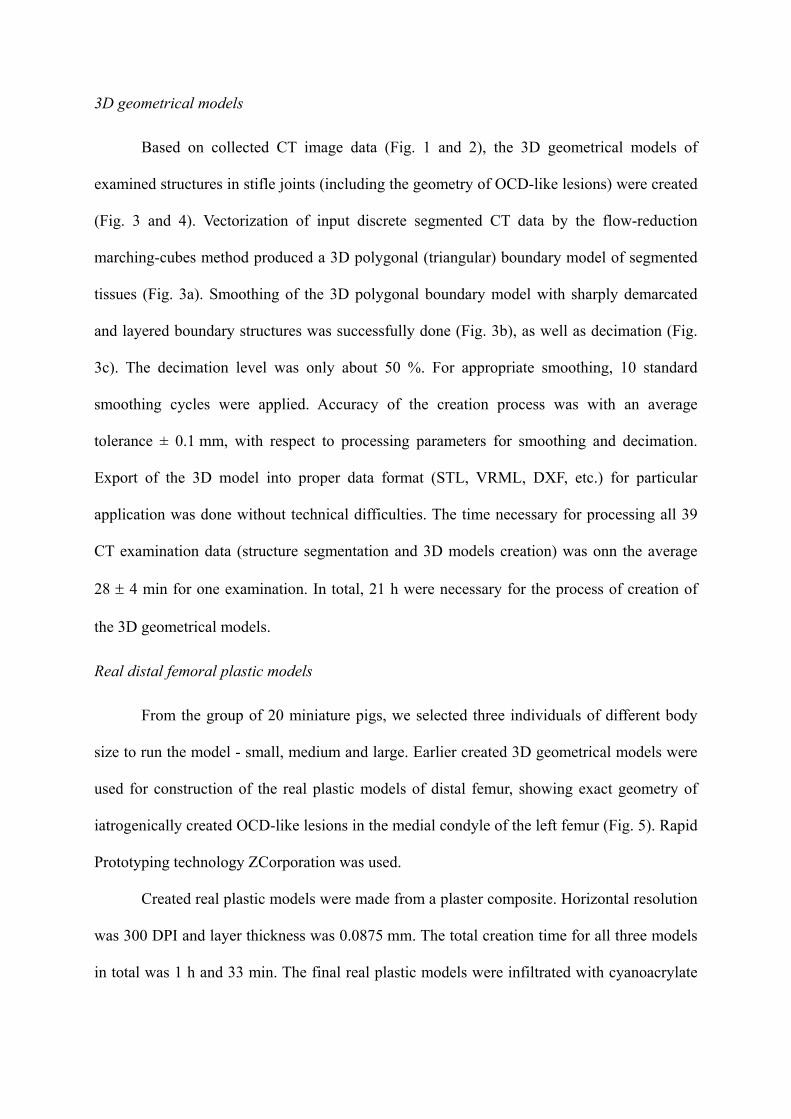
3D geometrical models
Based on collected CT image data (Fig. 1 and 2), the 3D geometrical models of
examined structures in stifle joints (including the geometry of OCD-like lesions) were created
(Fig. 3 and 4). Vectorization of input discrete segmented CT data by the flow-reduction
marching-cubes method produced a 3D polygonal (triangular) boundary model of segmented
tissues (Fig. 3a). Smoothing of the 3D polygonal boundary model with sharply demarcated
and layered boundary structures was successfully done (Fig. 3b), as well as decimation (Fig.
3c). The decimation level was only about 50 %. For appropriate smoothing, 10 standard
smoothing cycles were applied. Accuracy of the creation process was with an average
tolerance ± 0.1 mm, with respect to processing parameters for smoothing and decimation.
Export of the 3D model into proper data format (STL, VRML, DXF, etc.) for particular
application was done without technical difficulties. The time necessary for processing all 39
CT examination data (structure segmentation and 3D models creation) was onn the average
28 ± 4 min for one examination. In total, 21 h were necessary for the process of creation of
the 3D geometrical models.
Real distal femoral plastic models
From the group of 20 miniature pigs, we selected three individuals of different body
size to run the model - small, medium and large. Earlier created 3D geometrical models were
used for construction of the real plastic models of distal femur, showing exact geometry of
iatrogenically created OCD-like lesions in the medial condyle of the left femur (Fig. 5). Rapid
Prototyping technology ZCorporation was used.
Created real plastic models were made from a plaster composite. Horizontal resolution
was 300 DPI and layer thickness was 0.0875 mm. The total creation time for all three models
in total was 1 h and 33 min. The final real plastic models were infiltrated with cyanoacrylate
for their surface reinforcement. The accuracy of the creation process was on the average
± 0.1 mm.
Discussion
In this study, we concentrated on 3D geometry modelling of osteochondrosis-like
iatrogenic lesions in the medial femoral condyle of miniature pigs. The real plastic models of
the distal femur will serve as templates for press-and-fit scaffolds. The scaffold will be made
as “anatomical (custom-made) prosthesis” for each experimental animal in future study and
will be seeded with mesenchymal stem cells. It will be finally implanted into iatrogenically
created OCD-like lesion to enhance healing of this articular cartilage defect. Even though one
animal died due to anesthetic complications during the first CT examination eight weeks after
the surgery, we were able to collect a very representative sample of CT data necessary for
creating the real plastic distal femoral models.
Because the scanned animals were under general anesthesia, our experimental CT
examinations have no movement artifacts. The structures of our interest had relatively good
contrast when compared to other tissues. Therefore, we did not encounter any problem with
tissue segmentation. The whole process could be almost fully automatic and thus was quite
fast.
To achieve tissue distribution in the scanned volume, tissue segmentation of input CT
data has to be performed. Source CT data describe the distribution of tissue density
(Hounsfield units) in the volume of the scanned body part. Density values of soft and hard
tissues in the body do not overlap. For example, the density range for cortical bone is 1200–
1800 HU, for cancellous bone 200–1200 HU, for cartilage 800–1200 HU, and for soft tissues
200–400 HU). Simple thresholding or better adaptive thresholding (Lakare 2000) was
successfully used for their separation by cortical bone density. For input CT data filtering
different smoothing filters (median, Gaussian or anisotropic filtering) can be used. In the
study, we used the anisotropic method because we have better experience with anisotropic
filtering which removes noise while well preserving tissue boundary (Wang et al. 1997).
Input data for the 3D geometrical model creation process included segmented CT data which
had discrete voxel, 3D-based representation. However, boundary (polygonal, vector-based)
representation is needed for the creation of our 3D models. Hence discrete representation has
to be changed to vector representation. Discrete data were visualized by methods of volume
rendering which did not require segmentation (Fig. 2). However, various 3D operations with
tissue models still have to be performed: real plastic model creation, scaffold template,
surgery simulation, planning, measurements, analysis and data processing. Therefore, the 3D-
vector (geometrical) models were necessary for these tasks (Fig. 4).
In three pigs of different size, the 3D geometrical models were used to construct the
real plastic models of the distal femoral component of the stifle joint, including iatrogenic
geometry of OCD-like lesions. The accuracy of created models (both virtual and real) had
average tolerance of ± 0.5 mm. It is influenced mainly by the quality of CT examination.
Other processes (3D geometrical models and real plastic-model creation) had the average
accuracy of ± 0.1 mm. The accuracy of the real plastic models (in average tolerance
± 0.5 mm) which was achieved in our study is fully sufficient for our purposes and suggested
possible applications.
Based on the prepared 3D tissue geometrical models (bone, cartilage etc.) it is possible
to create real plastic models of the selected tissues. For the task, it is possible to use two
technologies, CNC (computer numeric control) milling and rapid prototyping. CNC milling
technology is thetraditional technology of mechanical engineering for cutting material pieces
from used material stock.The main advantages of this technology are the wide range of
usable plastic materials, high accuracy (0.01 mm) and surface quality (3.2 μm) level. The
main disadvantages are the long milling time, time-consuming and demanding process of
CNC data preparation and geometrical limitations. The technology (5D (5 axes) milling
machine AZK HWT D-442 5D CNC) is available at our department. However, we prefer the
other one.
Rapid prototyping technology creates 3D real plastic models directly by a computer,
step-by-step from a series of planar parallel thin material layers. At our department, we have
the RP machine Z310 ZCorporation which creates 3D real models by printing glue on a
plaster layer (Fig. 5). The main advantages of this technology are the fully automatic process
of real model formation, free geometry without limits, fast forming process (hours). The main
disadvantages are accuracy at the level of 0.1 mm, coarse surface quality, limited usable
materials (plaster composite, resin etc.). When different material is needed, it is possible to
make templates and final models are then cast from the appropriate material (inert Ebalta SG
2000 technical resin, for example).
Conclusions
This work demonstrates the possibilities and contributions of 3D geometrical
modelling in the treatment of stifle joint cartilage injuries. Input data for the processes
includes 3D image data from realised CT examinations. Concrete procedure of the
construction of 3D geometrical and real plastic models of anatomic structures (femoral
component of the stifle joint) were proposed and made. The common procedure was
developed and accommodated specifically for the distal femoral model in miniature pigs.
Evaluation of the process was done on experimental CT examinations of twenty
animals. On this sample of experimental animals, we optimized our proposed procedure for
3D geometrical and real modelling of joint structures. The created virtual (computer) 3D
geometrical models of the distal femur might be further used for more precise evaluation of
stifle-joint surface defects, surgery planning, simulation, navigation, or possibly training. In
vitro made Real plastic models made in vitro can be used as templates for the press-and-fit
collagen scaffold-preparing process. These scaffolds with MSC are expected to be used for
articular cartilage-repair enhancement.
Thec acquired experience will be used in the near future in the next part of our
research project dealing with cartilage repair based on press-and-fit implantation of different
scaffolds seeded with mesenchymal stem cells into iatrogenically created lesions simulating
osteochondrosis of the knee.
Acknowledgements
This work was supported by the Ministry of Education, Youth and Sport of the Czech
Republic (NPV II Research Project 2B06130) and by Grant Agency AGEL-MH.
References
BALENDRAN B: A direct smoothing method for surface meshes. In: Proceedings, 8th
International Meshing Roundtable, South Lake Tahoe, 1999, 189–193.
BANKMAN IN: Handbook of medical imaging: Processing and analysis, Academic Press,
Orlando, FL, 2000.
BURNSTEIN D, BASHIR A, GRAY M: MRI techniques in early stages of cartilage disease.
Invest Radiol 8: 409–430, 2000.
CERNOCHOVA P, KANOVSKA K, KRSEK P, KRUPA P: Application of geometric
biomodels for autotransplantation of impacted canines. In: World Journal of
Orthodontics, Paris, 2005, p 1.
DISLER DG, MCCAULEY TR, KELMAN CG: Fat-suppresed three-dimensional spoiled
gradient-echo MR imaging hyaline cartilage defects in the knee: comparison with
standard MR imaging and arthroscopy. AJR 167: 127–132, 1996.
GARLAND M, HECKBERT P: Surface simplification using quadric error metrics. In:
Siggraph'97 Conference Proceedings, 1997, pp. 209–216.
HALL RK: The role of CT, MRI and 3D imaging in the diagnosis of temporomandibular joint
and other orofacial disorders in children. Aust Orthod J. 13: 86–94, 1994.
HAMARNEH G, CHUA V, BORDALO-RODRIGUESB M, SCHWEITZERC M:
Deformation Analysis of Hoffa’s Fat Pad from CT images of Knee Flexion and
Extension. Medical Imaging 57: 527–534, 2005.
HUECK AF, STEIGER P, STOLLER DW, GUER CC, GENANT HK: Quantification of knee
joint fluid volume by MR imaging and CT using three-dimensional data processing. J
Comput Assist Tomogr 13: 287–293, 1989.
KRAMER J, STIGLBAUER R, ENGEL A, PRAYER L, IMHOF H: MR contrast
arthrography (MRA) in osteochondritis dissecans. J Comput Assist Tomogr 16: 254–
260, 1992.
KRSEK P: Flow Reduction Marching Cubes Algorithm. In: Proceedings of ICCVG Springer,
Warsaw, 2005, pp 100–106.
KRSEK P, SPANEL M, CERNOCHOVA P, KANOVSKA K, KRUPA P, STOKLAS J,
MOLITOR M: 3D Human Tissues Modelling In Clinical Applications. In: Medical
Information Visualisation, IEEE CS, GB, 2006
KRUPA P, KRSEK P, CERNOCHOVA P, MOLITOR M: 3D real modelling and CT
biomodels application in facial surgery. In: Neuroradiology, Springer, Berlin, 2004,
p 1.
LORENSEN W, CLINE H: Marching cubes, A high resolution 3D surface construction
algorithm. In: Siggraph '87 Conference Proceedings, 1987, pp 163–169.
POTTER HG, LINLATER JM, ALLEN AA, HANNAFIN JA, HAA SB: MR imaging of
articular catilage of the knee: a prospective evaluation using fast spin-echo imaging. J
Bone Joint Surgery Am 80: 1276–1284, 1998.
RUBENSTEIN JD, LI JG, MAJUMDAR S, HENKELMAN RM: Imaging resolution and
signal-to-noise ratio requirements for MR Imaging of degenerative cartilage defects.
AJR 155: 549–553, 1990.
SCHROEDER WJ, ZARGE JA, LORENSEN WE: Decimation of triangle meshes. In:
Siggraph'92 Conference Proceedings, 1992, pp 65-70.
SPANEL M, KRSEK P: Vector-based Medical Image Segmentation using Adaptive Delaunay
Triangulation, In: Proceedings of the Sixth IASTED International Conference on
Visualization, Imaging, and Image Procesing, ACTA Press, Palma de Mallorca, 2006,
p 6.
TAUBIN G.: Geometric signal processing on polygonal meshes. In: Eurographics 2000 State
of the Art Report (STAR), 2000.
WANG Y, JIN JS, HILLER J: An adaptive nonlinear diffusion algorithm for image filtering.
Imaging 3028: 26–37, 1997.
Author for correspondence
Petr Krupa, Klinika zobrazovacích metod, FN u sv. Anny, Lékařská fakulta Masarykovy
univerzity, Pekařská 53, 656 91 Brno, Czech Republic; e-mail: [email protected].
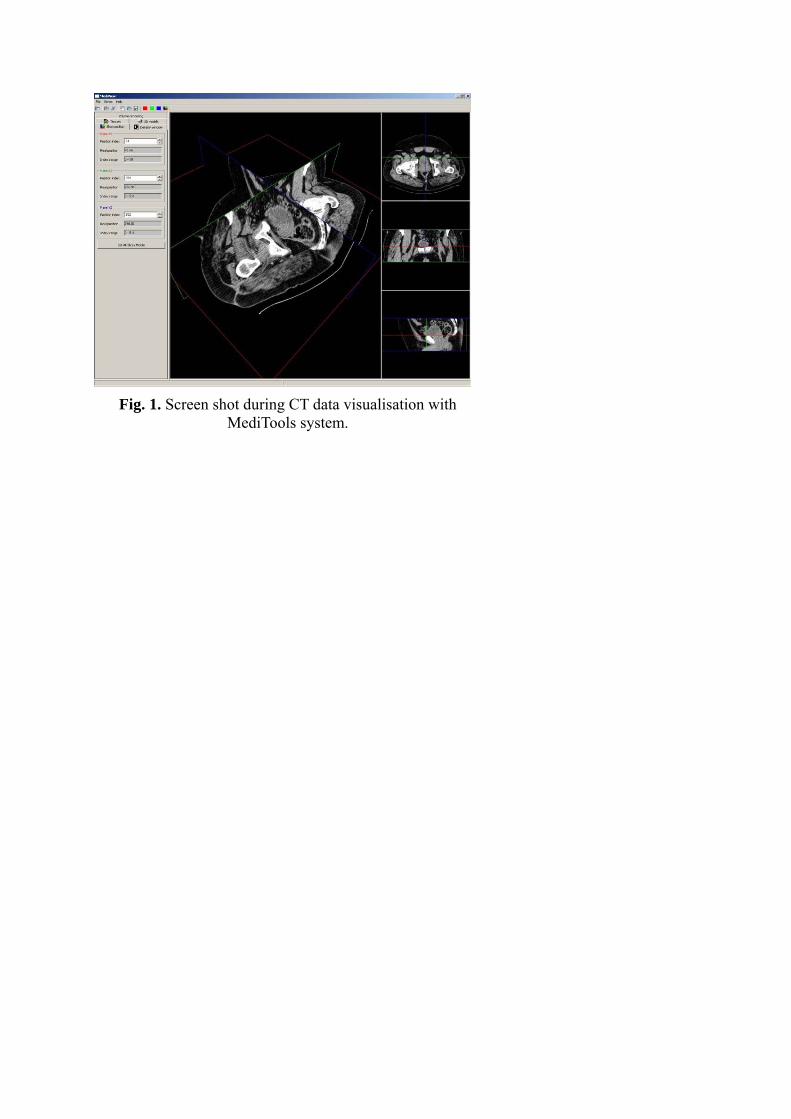
Fig. 1. Screen shot during CT data visualisation with
MediTools system.
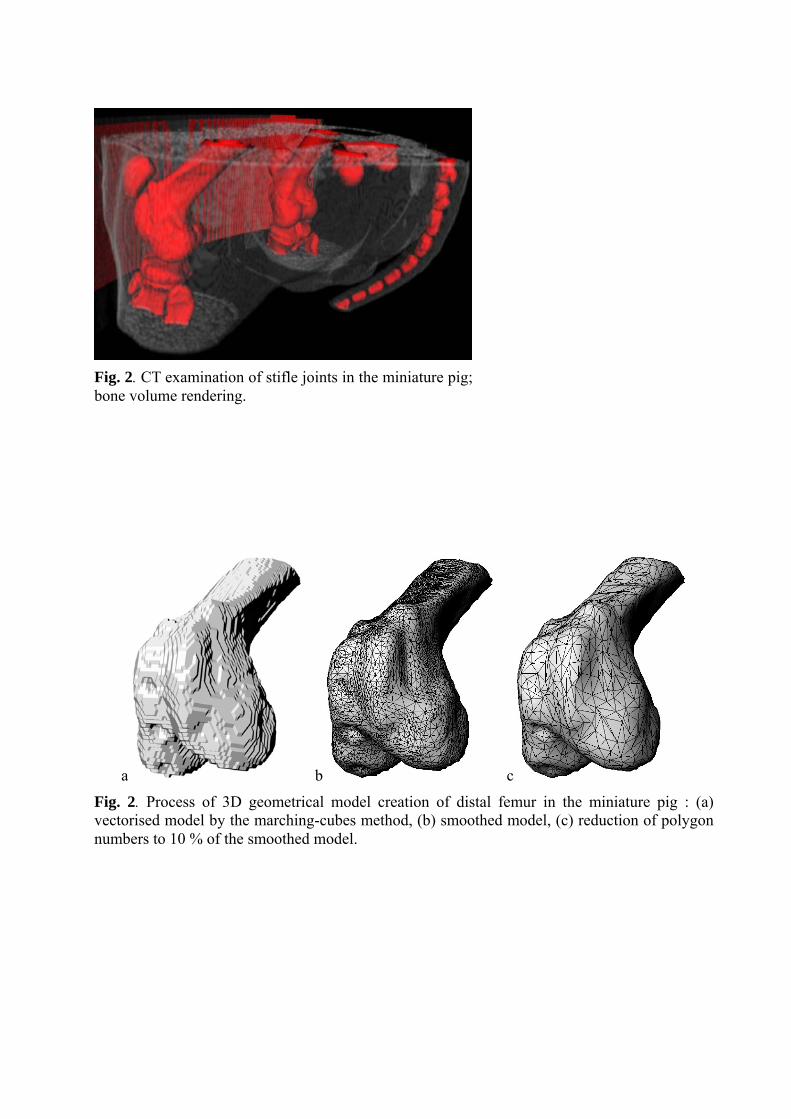
Fig. 2. CT examination of stifle joints in the miniature pig;bone volume rendering.
a b c
Fig. 2. Process of 3D geometrical model creation of distal femur in the miniature pig : (a) vectorised model by the marching-cubes method, (b) smoothed model, (c) reduction of polygon numbers to 10 % of the smoothed model.
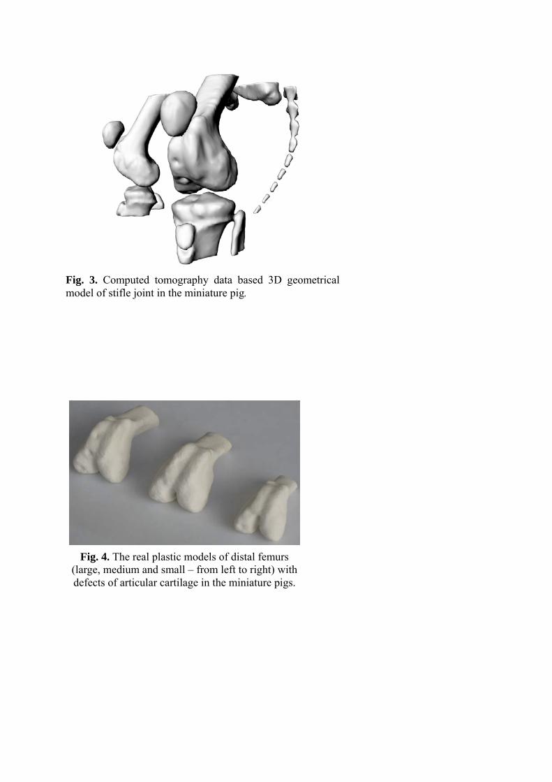
Fig. 3. Computed tomography data based 3D geometrical model of stifle joint in the miniature pig.
Fig. 4. The real plastic models of distal femurs
(large, medium and small – from left to right) with defects of articular cartilage in the miniature pigs.