Embed Size (px)
Citation preview
USE CASE DIAGRAMS
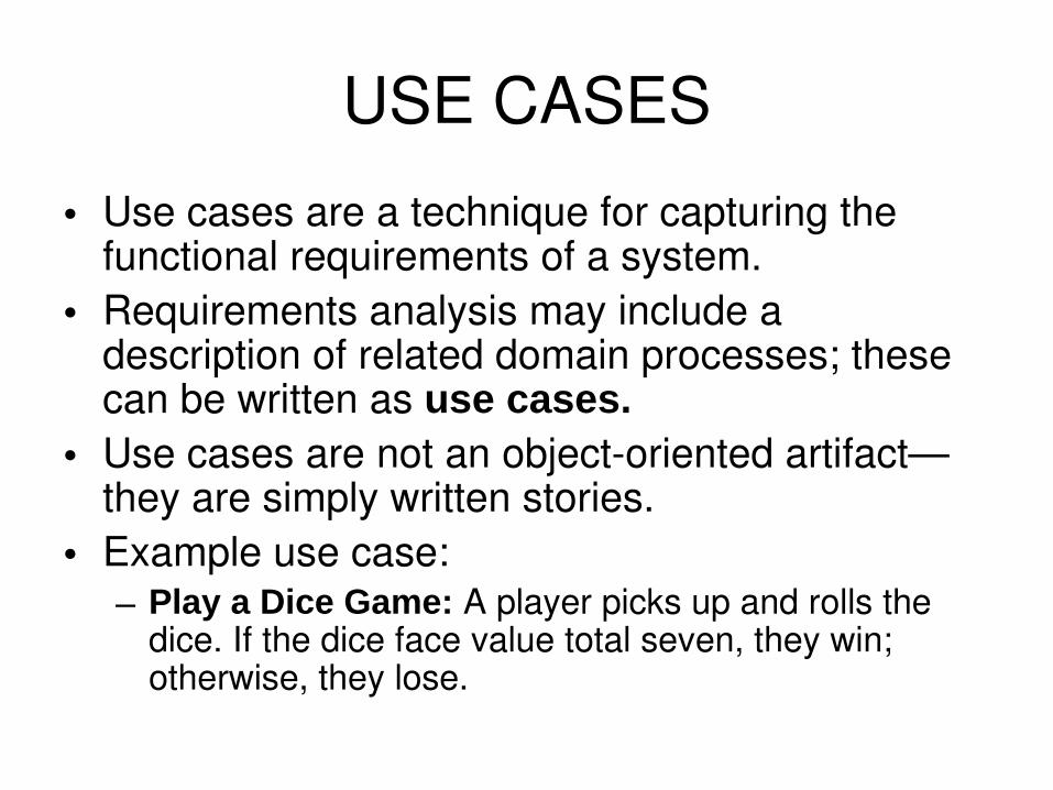
USE CASES• Use cases are a technique for capturing the
functional requirements of a system. • Requirements analysis may include a
description of related domain processes; these can be written as use cases.
• Use cases are not an objectoriented artifact—they are simply written stories.
• Example use case: – Play a Dice Game: A player picks up and rolls the
dice. If the dice face value total seven, they win; otherwise, they lose.
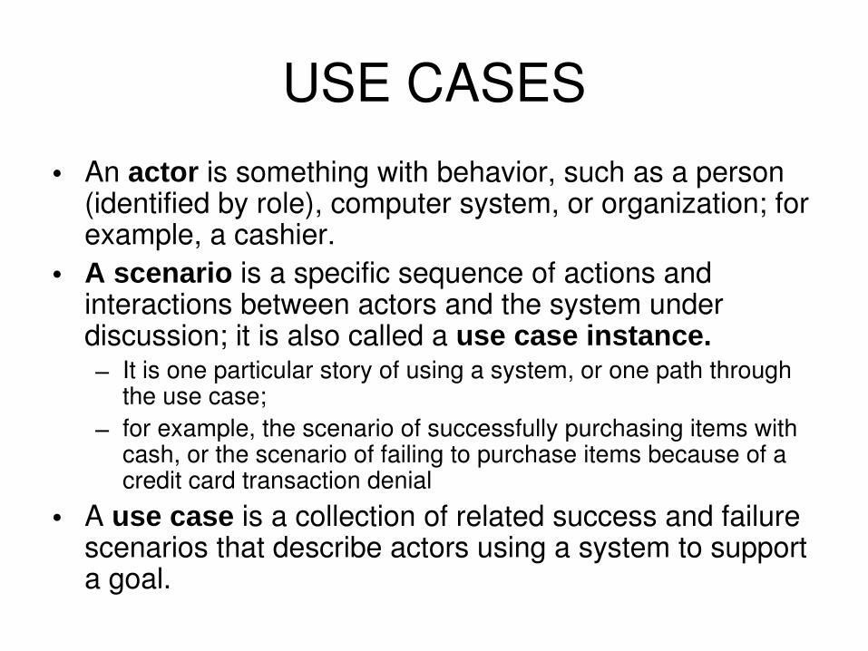
USE CASES• An actor is something with behavior, such as a person
(identified by role), computer system, or organization; for example, a cashier.
• A scenario is a specific sequence of actions and interactions between actors and the system under discussion; it is also called a use case instance.– It is one particular story of using a system, or one path through
the use case; – for example, the scenario of successfully purchasing items with
cash, or the scenario of failing to purchase items because of a credit card transaction denial
• A use case is a collection of related success and failure scenarios that describe actors using a system to support a goal.
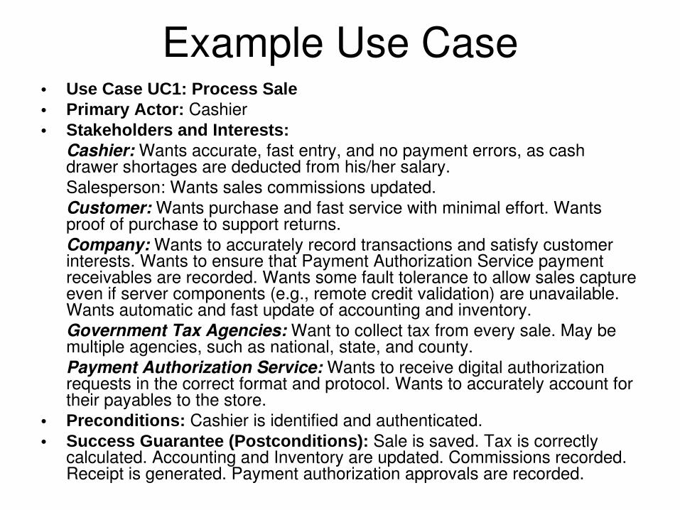
Example Use Case• Use Case UC1: Process Sale• Primary Actor: Cashier• Stakeholders and Interests:
Cashier: Wants accurate, fast entry, and no payment errors, as cash drawer shortages are deducted from his/her salary.Salesperson: Wants sales commissions updated. Customer: Wants purchase and fast service with minimal effort. Wants proof of purchase to support returns.Company: Wants to accurately record transactions and satisfy customer interests. Wants to ensure that Payment Authorization Service payment receivables are recorded. Wants some fault tolerance to allow sales capture even if server components (e.g., remote credit validation) are unavailable. Wants automatic and fast update of accounting and inventory.Government Tax Agencies: Want to collect tax from every sale. May be multiple agencies, such as national, state, and county.Payment Authorization Service: Wants to receive digital authorization requests in the correct format and protocol. Wants to accurately account for their payables to the store.
• Preconditions: Cashier is identified and authenticated.• Success Guarantee (Postconditions): Sale is saved. Tax is correctly
calculated. Accounting and Inventory are updated. Commissions recorded. Receipt is generated. Payment authorization approvals are recorded.
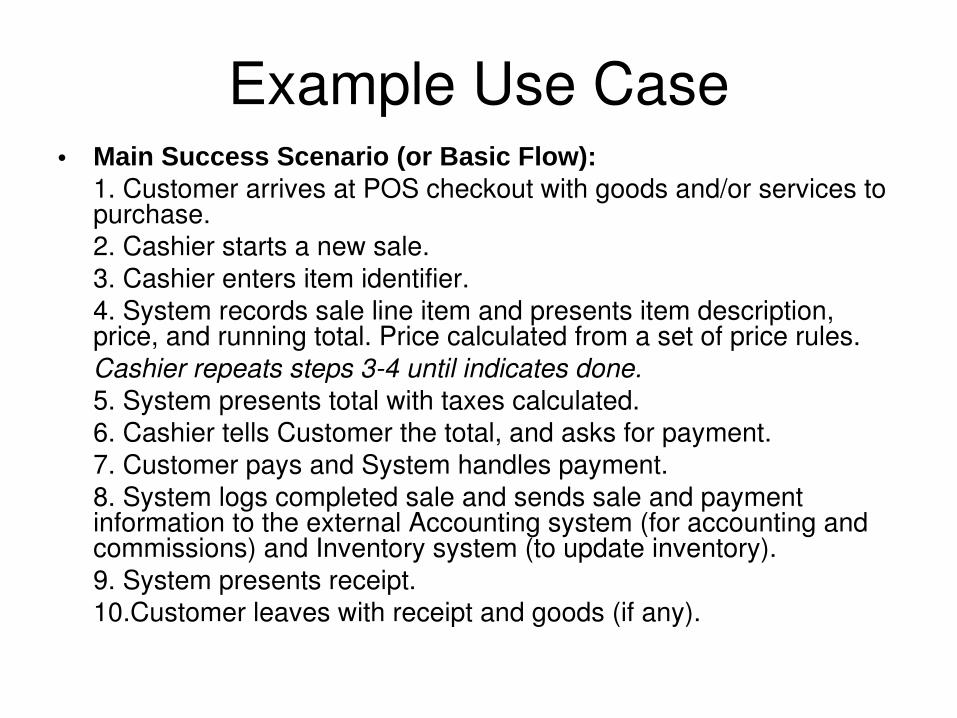
• Main Success Scenario (or Basic Flow):1. Customer arrives at POS checkout with goods and/or services to purchase.2. Cashier starts a new sale.3. Cashier enters item identifier.4. System records sale line item and presents item description, price, and running total. Price calculated from a set of price rules.Cashier repeats steps 34 until indicates done.5. System presents total with taxes calculated.6. Cashier tells Customer the total, and asks for payment.7. Customer pays and System handles payment.8. System logs completed sale and sends sale and payment information to the external Accounting system (for accounting and commissions) and Inventory system (to update inventory).9. System presents receipt.10.Customer leaves with receipt and goods (if any).
Example Use Case
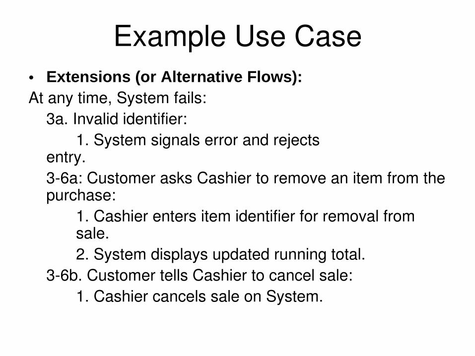
• Extensions (or Alternative Flows):At any time, System fails:
3a. Invalid identifier:1. System signals error and rejects
entry. 36a: Customer asks Cashier to remove an item from the purchase:
1. Cashier enters item identifier for removal from sale.2. System displays updated running total.
36b. Customer tells Cashier to cancel sale:1. Cashier cancels sale on System.
Example Use Case
Use Case Diagrams• Use cases are text documents, not
diagrams, and usecase modeling is primarily an act of writing text, not drawing.
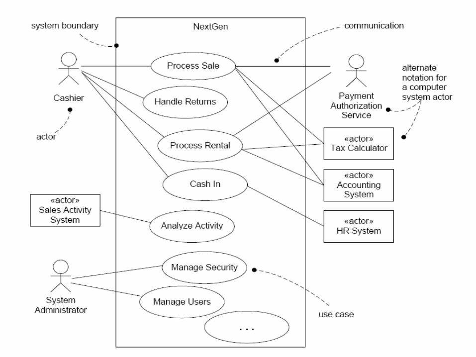
• However, the UML defines a use case diagram to illustrate the names of use cases and actors, and their relationships
ACTORS• Users of a software system are represented as
actors in a usecase diagram. • Actors represent specific users, groups of users,
organizational users and even external software systems.
• For example, a library may employ several librarians. Because all of these librarians will access the system in the same manner, a single actor (Librarian) represents them.
USE CASES• Actors maintain relationships with use
cases. • A use case is a description of some
software activity that an actor may initiate.• For example, a librarian can check out an
asset, such as a book. This activity is represented as a use case.
Usecase relationships• Use cases can participate in four types of
relationships: – association, – generalization,– include and – extend.
• Each relationship has its own purpose and notation.
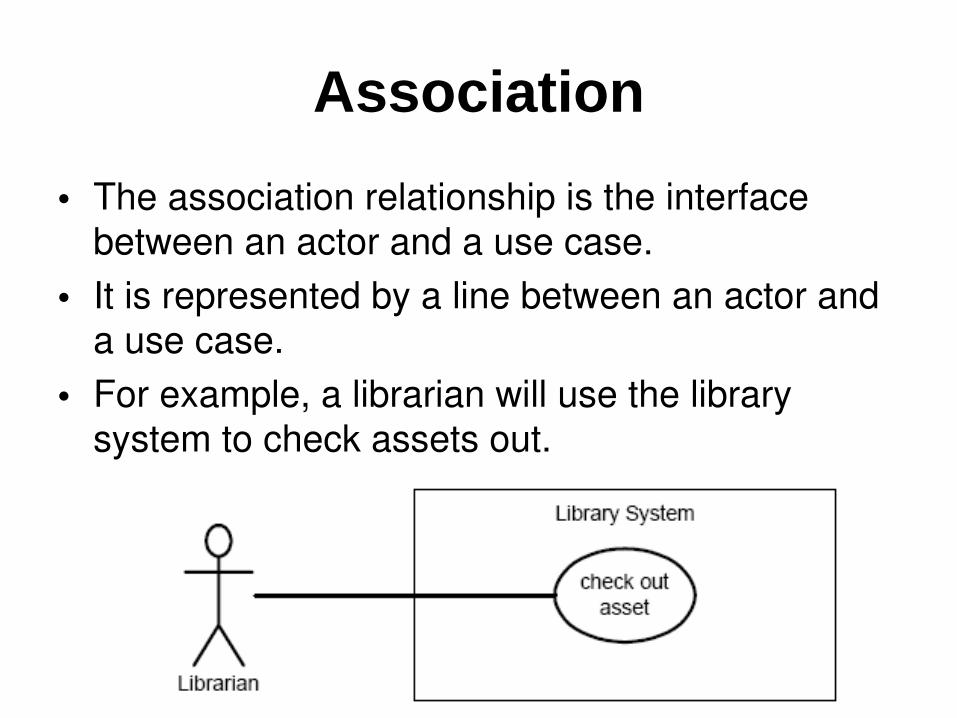
Association• The association relationship is the interface
between an actor and a use case. • It is represented by a line between an actor and
a use case. • For example, a librarian will use the library
system to check assets out.
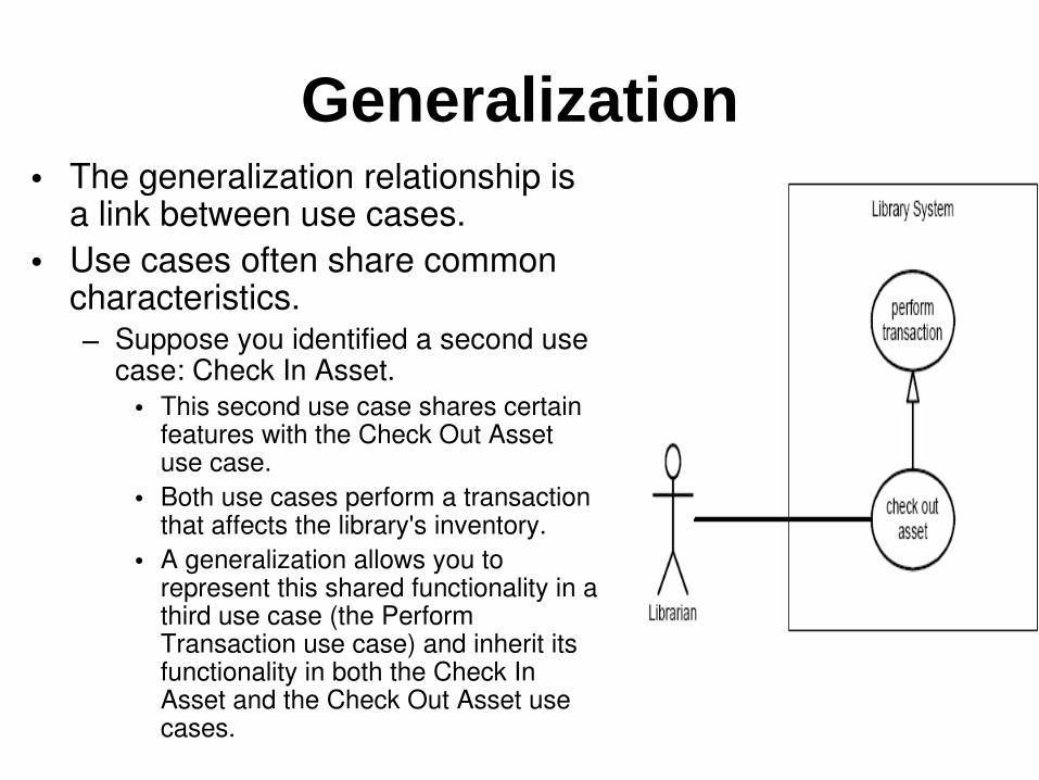
Generalization• The generalization relationship is
a link between use cases. • Use cases often share common
characteristics. – Suppose you identified a second use
case: Check In Asset. • This second use case shares certain
features with the Check Out Asset use case.
• Both use cases perform a transaction that affects the library's inventory.
• A generalization allows you to represent this shared functionality in a third use case (the Perform Transaction use case) and inherit its functionality in both the Check In Asset and the Check Out Asset use cases.
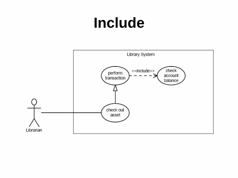
Include• The include relationship allows one use case to include
the functionality of another.• Before an asset can be checked out, the system must
verify that the patron does not owe any overdue fines. • An include relationship allows the Perform Transaction
use case to include the functionality of a Check Account Balance use case.
• The include relationship is represented by a dashed line with an arrowhead.
• The word <<include>> is superimposed above the line to distinguish an include relationship from an extend relationship.
• The arrow points from the use case that includes the additional functionality to the use case being included.
Include
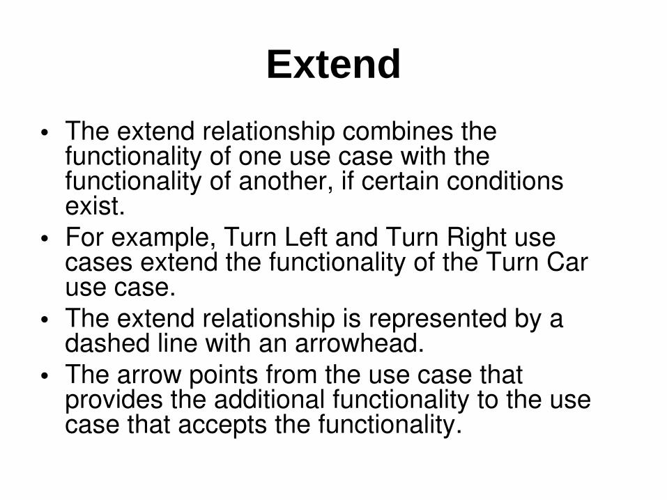
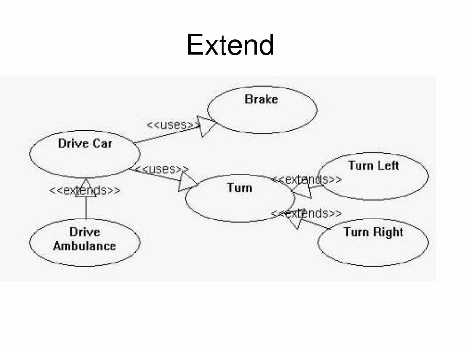
Extend• The extend relationship combines the
functionality of one use case with the functionality of another, if certain conditions exist.
• For example, Turn Left and Turn Right use cases extend the functionality of the Turn Car use case.
• The extend relationship is represented by a dashed line with an arrowhead.
• The arrow points from the use case that provides the additional functionality to the use case that accepts the functionality.
Extend
Use Case Diagrams