Embed Size (px)
Citation preview
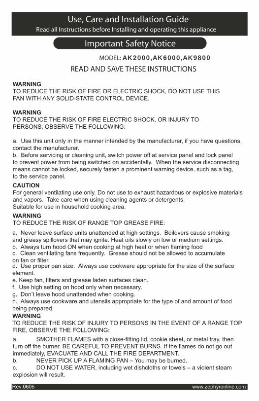
Read all Instructions before Installing and operating this appliance
MODEL: AK2000,AK6000,AK9800
Important Safety Notice
Use, Care and Installation Guide
WARNINGTO REDUCE THE RISK OF FIRE OR ELECTRIC SHOCK, DO NOT USE THISFAN WITH ANY SOLID-STATE CONTROL DEVICE.
WARNINGTO REDUCE THE RISK OF FIRE ELECTRIC SHOCK, OR INJURY TOPERSONS, OBSERVE THE FOLLOWING:
a. Use this unit only in the manner intended by the manufacturer, if you have questions,contact the manufacturer.b. Before servicing or cleaning unit, switch power off at service panel and lock panelto prevent power from being switched on accidentally. When the service disconnectingmeans cannot be locked, securely fasten a prominent warning device, such as a tag,to the service panel.CAUTIONFor general ventilating use only. Do not use to exhaust hazardous or explosive materials and vapors. Take care when using cleaning agents or detergents.Suitable for use in household cooking area.WARNINGTO REDUCE THE RISK OF RANGE TOP GREASE FIRE:
a. Never leave surface units unattended at high settings. Boilovers cause smokingand greasy spillovers that may ignite. Heat oils slowly on low or medium settings.b. Always turn hood ON when cooking at high heat or when flaming food
c. Clean ventilating fans frequently. Grease should not be allowed to accumulateon fan or filter.d. Use proper pan size. Always use cookware appropriate for the size of the surfaceelement.e. Keep fan, filters and grease laden surfaces clean.f. Use high setting on hood only when necessary.g. Don’t leave hood unattended when cooking.h. Always use cookware and utensils appropriate for the type of and amount of food being prepared.WARNINGTO REDUCE THE RISK OF INJURY TO PERSONS IN THE EVENT OF A RANGE TOPFIRE, OBSERVE THE FOLLOWING:a. SMOTHER FLAMES with a close-fitting lid, cookie sheet, or metal tray, then turn off the burner. BE CAREFUL TO PREVENT BURNS. If the flames do not go out immediately, EVACUATE AND CALL THE FIRE DEPARTMENT. b. NEVER PICK UP A FLAMING PAN – You may be burned. c. DO NOT USE WATER, including wet dishcloths or towels – a violent steam explosion will result.
Rev:0605 www.zephyronline.com
READ AND SAVE THESE INSTRUCTIONS

Important Safety NoticeRead and save these instructions
d. Use an extinguisher ONLY if: 1. You know you have a Class ABC extinguisher, and you already know how to operate it. 2. The fire is small and contained in the area where it started. 3. The fire department is being called. 4. You can fight the fire with your back to an exit WARNINGTO REDUCE THE RISK OF FIRE, ELECTRIC SHOCK OR INJURY TO PERSONS,OBSERVE THE FOLLOWING:
a. Installation work and electrical wiring must be done by qualified person (s) inaccordance with all applicable codes and standards. Including fire-rated construction.b. Sufficient air is needed for power combustion and exhausting of gases through the flue (chimney) of fuel burning equipment to prevent back drafting. Follow the heating equipment manufacturer’s guideline and safety standards such as those publishedby the National Fire Protection Association (NFPA) and the American Society forHeating, Refrigeration and Air Conditioning Engineers (ASHRAE) and the local codeauthorities.c. When cuttig or drilling into wall or ceiling, do not damage electrical wiring and otherhidden utilities.d. Ducted fans must always vent to the outdoors.
WARNINGTO REDUCE THE RISK OF FIRE, USE ONLY METAL DUCTWORK.
CAUTIONTo reduce risk of fire and to properly exhaust air outside - Do not vent exhaust air intospaces within walls, ceilings, attics, crawl spaces or garages.
WARNINGTO REDUCE THE RISK OF SHOCK, THIS FAN MUST BE INSTALLED WITH ANISOLATING WALL CONTROL/SWITCH.
OPERATIONAlways leave safety grills and filters in place. Without these components, operatingblowers could catch onto hair, fingers and loose clothing.
*NOTE: Please check www.zephyronline.com for revisions before doing any customwork.
MODEL: AK2000,AK6000,AK9800
e. If this unit is to be installed over a tub or shower, it must be marked as appropriate for theapplication and be connected to a GFCL (Ground Fault Interrupter protected branch circuit).g. NEVER place a switch where it can be reached from a tub or shower.h. Make sure the power is off before installing, wiring or maintenancing.
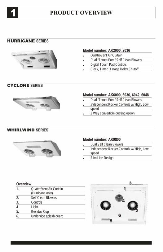
PRODUCT OVERVIEW
WHIRLWIND SERIES
HURRICANE SERIES
CYCLONE SERIES
1
Model number: AK2000, 2036, QuattroVent Air Curtain, Dual “Thrust-Fore" Self Clean Blowers, Digital Touch Pad Controls, Clock, Timer, 3 stage Delay Shutoff.
Model number: AK9800 , Dual Self Clean Blowers, Independent Rocker Controls w/ High, Low
speed, Slim Line Design
Overview1. QuattroVent Air Curtain
(Hurricane only)2. Self Clean Blowers3. Controls4. Light5. Residue Cup6. Underside splash guard
Model number: AK6000, 6036, 6042, 6048, Dual “Thrust-Fore" Self Clean Blowers, Independent Rocker Controls w/ High, Low
speed, 3 Way convertible ducting option
1
2
3
4
5
6
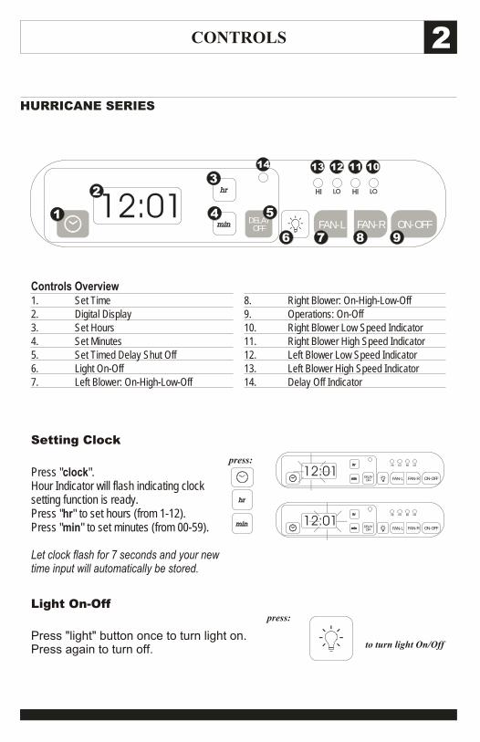
CONTROLS
HURRICANE SERIES
2
Controls Overview1. Set Time2. Digital Display3. Set Hours4. Set Minutes5. Set Timed Delay Shut Off6. Light On-Off7. Left Blower: On-High-Low-Off
8. Right Blower: On-High-Low-Off9. Operations: On-Off10. Right Blower Low Speed Indicator11. Right Blower High Speed Indicator12. Left Blower Low Speed Indicator13. Left Blower High Speed Indicator14. Delay Off Indicator
ON-OFF
hr hr
minmin
HI HILO LO
FAN-L FAN-RDELAYOFF
12:011
23
4 5
6 7 8 9
1011121314
Setting Clock
Press "clock".Hour Indicator will flash indicating clock setting function is ready.Press "hr" to set hours (from 1-12).Press "min" to set minutes (from 00-59).
Let clock flash for 7 seconds and your new time input will automatically be stored.
hr hr
minmin
press:
ON-OFF
hr hr
minmin
HI HILO LO
FAN-L FAN-RDELAYOFF
12:01
ON-OFF
hr hr
minmin
HI HILO LO
FAN-L FAN-RDELAYOFF
12:01
Light On-Off
Press "light" button once to turn light on. Press again to turn off.
press:
to turn light On/Off
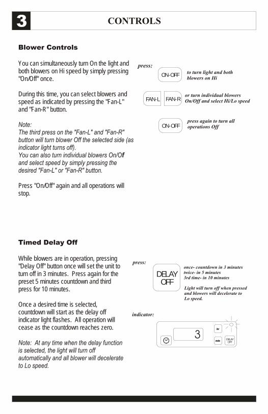
Blower Controls
You can simultaneously turn On the light and both blowers on Hi speed by simply pressing "On/Off" once.
During this time, you can select blowers and speed as indicated by pressing the "Fan-L" and "Fan-R" button.
Note: The third press on the "Fan-L" and "Fan-R" button will turn blower Off the selected side (as indicator light turns off).You can also turn individual blowers On/Off and select speed by simply pressing the desired "Fan-L" or "Fan-R" button.
Press "On/Off" again and all operations will stop.
CONTROLS3
press:to turn light and both blowers on Hi
ON-OFF
press again to turn all operations OffON-OFF
or turn individual blowers On/Off and select Hi/Lo speedFAN-L FAN-R
Timed Delay Off
While blowers are in operation, pressing "Delay Off" button once will set the unit to turn off in 3 minutes. Press again for the preset 5 minutes countdown and third press for 10 minutes.
Once a desired time is selected, countdown will start as the delay off indicator light flashes. All operation will cease as the countdown reaches zero.
Note: At any time when the delay function is selected, the light will turn off automatically and all blower will decelerate to Lo speed.
press:
indicator:
Light will turn off when pressed and blowers will decelerate to Lo speed.
once- countdown in 3 minutestwice- in 5 minutes3rd time- in 10 minutes
hr hr
minmin DELAYOFF
DELAYOFF
3
CONTROLS 4
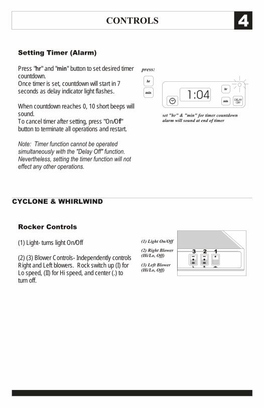
Setting Timer (Alarm)
Press "hr" and "min" button to set desired timer countdown.Once timer is set, countdown will start in 7 seconds as delay indicator light flashes.
When countdown reaches 0, 10 short beeps will sound.To cancel timer after setting, press "On/Off" button to terminate all operations and restart.
Note: Timer function cannot be operated simultaneously with the "Delay Off" function. Nevertheless, setting the timer function will not effect any other operations.
hr hr
minmin
press:
set "hr" & "min" for timer countdownalarm will sound at end of timer
hr hr
minmin DELAYOFF
1:04
Rocker Controls
(1) Light- turns light On/Off
(2) (3) Blower Controls- Independently controls Right and Left blowers. Rock switch up (I) for Lo speed, (II) for Hi speed, and center (.) to turn off.
(1) Light On/Off
(2) Right Blower(Hi/Lo, Off)
(3) Left Blower(Hi/Lo, Off)
CYCLONE & WHIRLWIND
RL
123
MAINTENANCE5
Self Clean Feature
All Zephyr Range Hoods are filter-less and are designed with a self clean feature. The centrifugal blower system automatically liquefies grease accumulated in its internal housing. All systems are equipped with dishwasher safe grease containers for its self clean function.
Grease and residue from cooking are often automatically liquefied and can accumulate in the containers from everyday use. Nevertheless, grease from cooking could also dry and adhered in its internal housing. Running the self clean function periodically will flush out the accumulated grease in the range hood’s internal housing.
Cleaning Frequency
Cleaning should be approximately once a month under normal use.
Detergent
Grease cutting detergent such as ‘409’ or its equivalent are recommended.
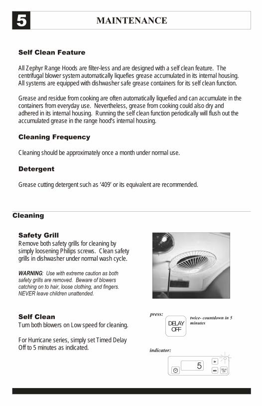
Safety GrillRemove both safety grills for cleaning by simply loosening Philips screws. Clean safety grills in dishwasher under normal wash cycle.
WARNING: Use with extreme caution as both safety grills are removed. Beware of blowers catching on to hair, loose clothing, and fingers. NEVER leave children unattended.
Self CleanTurn both blowers on Low speed for cleaning.
For Hurricane series, simply set Timed Delay Off to 5 minutes as indicated.
Cleaning
press:
indicator:
twice- countdown in 5 minutes
hr hr
minmin DELAYOFF
DELAYOFF
5
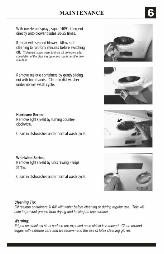
Hurricane Series:Remove light shield by turning counter-clockwise.
Clean in dishwasher under normal wash cycle.
Whirlwind Series:Remove light shield by unscrewing Philips screw.
Clean in dishwasher under normal wash cycle.
Cleaning Tip:Fill residue containers ¼ full with water before cleaning or during regular use. This will help to prevent grease from drying and tacking on cup surface.
Warning: Edges on stainless steel surface are exposed once shield is removed. Clean around edges with extreme care and we recommend the use of latex cleaning gloves.
MAINTENANCE 6
With nozzle on ‘spray’, squirt ‘409’ detergent directly onto blower blades 30-35 times.
Repeat with second blower. Allow self cleaning to run for 5 minutes before switching off. (If desired, spray water to rinse off detergent after completion of the cleaning cycle and run for another few minutes)
Remove residue containers by gently sliding out with both hands. Clean in dishwasher under normal wash cycle.
MAINTENANCE7
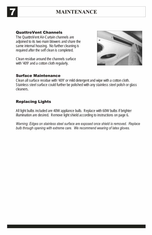
QuattroVent ChannelsThe QuattroVent Air-Curtain channels are adjoined to its two main blowers and share the same internal housing. No further cleaning is required after the self clean is completed.
Clean residue around the channels surface with ‘409’ and a cotton cloth regularly.
Replacing Lights
All light bulbs included are 40W appliance bulb. Replace with 60W bulbs if brighter illumination are desired. Remove light shield according to instructions on page 6.
Warning: Edges on stainless steel surface are exposed once shield is removed. Replace bulb through opening with extreme care. We recommend wearing of latex gloves.
Surface MaintenanceClean all surface residue with ‘409’ or mild detergent and wipe with a cotton cloth. Stainless steel surface could further be polished with any stainless steel polish or glass cleaners.
INSTALLATION 8
REQUIREMENTS
ACCESSORIES
WARNING
Installation of this product is intended for qualified installers, service technicians, or persons with similar qualified background. DO NOT attempt to install this appliance yourself. Injury could result form installing the unit due to lack of appropriate electrical knowledge and technical background. Improper installation, adjustment, alteration, service or maintenance can cause injury or property damage and the warranty on the product automatically becomes void. Installation of this product must conform with all local codes. All connections must be electrically grounded and ducting must be properly vented outside in accordance to codes. Never duct exhaust into attics, within walls, crawlspaces, garages, or anywhere inside the house which might cause grease fire. All duct joints must be properly inspected, taped and sealed.
Edges are exposed around the duct opening and once the bottom grease shield is removed. Be careful when handling the sharp edges. Wearing protective gloves and appropriate work clothing is recommended.
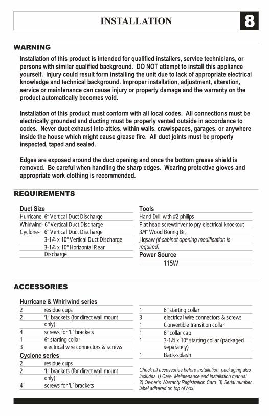
Duct SizeHurricane- 6“ Vertical Duct DischargeWhirlwind- 6“ Vertical Duct DischargeCyclone- 6“ Vertical Duct Discharge
3-1/4 x 10“ Vertical Duct Discharge3-1/4 x 10“ Horizontal Rear Discharge
Hurricane & Whirlwind series2 residue cups2 ‘L’ brackets (for direct wall mount
only)4 screws for ‘L’ brackets1 6“ starting collar3 electrical wire connectors & screws
Cyclone series2 residue cups2 ‘L’ brackets (for direct wall mount
only)4 screws for ‘L’ brackets
1 6“ starting collar3 electrical wire connectors & screws1 Convertible transition collar1 6“ collar cap1 3-1/4 x 10“ starting collar (packaged
separately)1 Back-splash
Check all accessories before installation, packaging also includes 1) Care, Maintenance and installation manual 2) Owner’s Warranty Registration Card 3) Serial number label adhered on top of box.
ToolsHand Drill with #2 philipsFlat head screwdriver to pry electrical knockout3/4“ Wood Boring BitJigsaw (if cabinet opening modification is required)
Power Source115W
INSTALLATION9
MIN. 18” MAX 30”
net width
DUCT OPENING
CLEARANCES
Front
RearFront
Rear
Wall
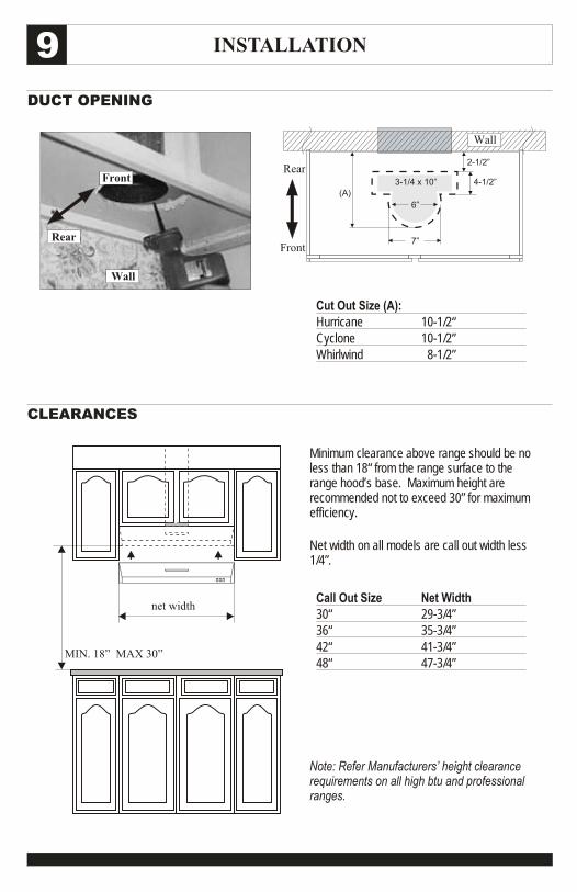
Minimum clearance above range should be no less than 18“ from the range surface to the range hood’s base. Maximum height are recommended not to exceed 30” for maximum efficiency.
Net width on all models are call out width less 1/4”.
Note: Refer Manufacturers’ height clearance requirements on all high btu and professional ranges.
Call Out Size Net Width30“ 29-3/4”36“ 35-3/4”42“ 41-3/4”48“ 47-3/4”
Cut Out Size (A):Hurricane 10-1/2“Cyclone 10-1/2”Whirlwind 8-1/2”
6”
7”
2-1/2”
(A)
4-1/2”3-1/4 x 10”
Wall
INSTALLATION 10STEP 1
STEP 3
STEP 5
STEP 2
STEP 4
STEP 6 (also refer notes on pg. 16)
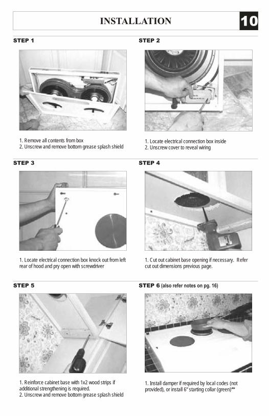
1. Remove all contents from box2. Unscrew and remove bottom grease splash shield
1. Locate electrical connection box knock out from left rear of hood and pry open with screwdriver
1. Cut out cabinet base opening if necessary. Refer cut out dimensions previous page.
1. Reinforce cabinet base with 1x2 wood strips if additional strengthening is required. 2. Unscrew and remove bottom grease splash shield
1. Install damper if required by local codes (not provided), or install 6“ starting collar (green)**
1. Locate electrical connection box inside2. Unscrew cover to reveal wiring
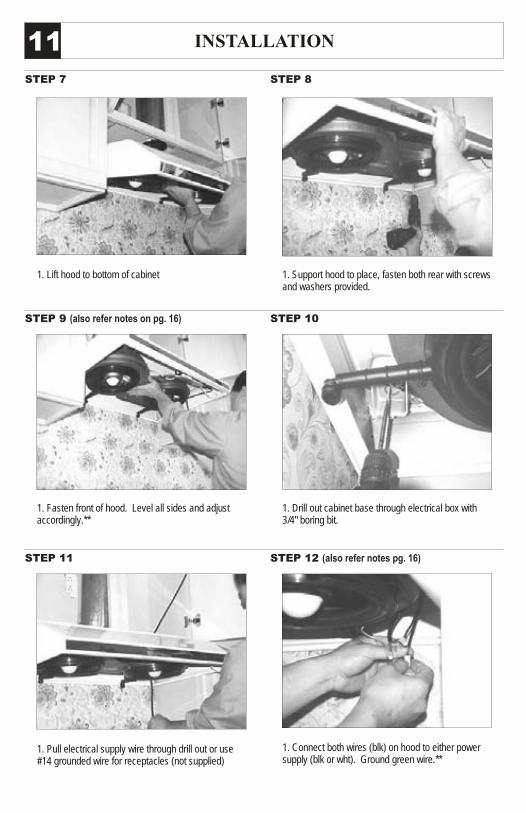
INSTALLATION11STEP 7
STEP 9 (also refer notes on pg. 16)
STEP 11
STEP 8
STEP 10
STEP 12 (also refer notes pg. 16)
1. Lift hood to bottom of cabinet 1. Support hood to place, fasten both rear with screws and washers provided.
1. Fasten front of hood. Level all sides and adjust accordingly.**
1. Drill out cabinet base through electrical box with 3/4" boring bit.
1. Pull electrical supply wire through drill out or use #14 grounded wire for receptacles (not supplied)
1. Connect both wires (blk) on hood to either power supply (blk or wht). Ground green wire.**
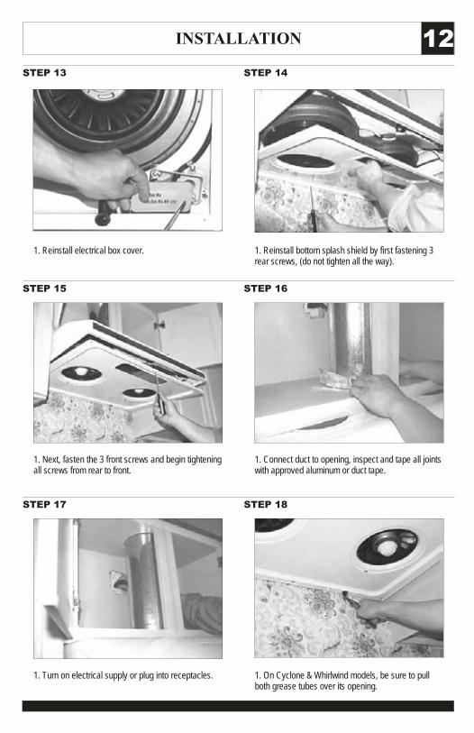
INSTALLATION 12STEP 13
STEP 15
STEP 17
STEP 14
STEP 16
STEP 18
1. On Cyclone & Whirlwind models, be sure to pull both grease tubes over its opening.
1. Turn on electrical supply or plug into receptacles.
1. Reinstall electrical box cover.
1. Next, fasten the 3 front screws and begin tightening all screws from rear to front.
1. Connect duct to opening, inspect and tape all joints with approved aluminum or duct tape.
1. Reinstall bottom splash shield by first fastening 3 rear screws, (do not tighten all the way).
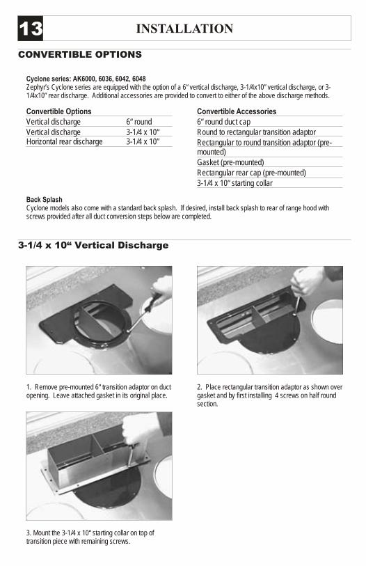
INSTALLATION13CONVERTIBLE OPTIONS
3-1/4 x 10“ Vertical Discharge
1. Remove pre-mounted 6“ transition adaptor on duct opening. Leave attached gasket in its original place.
3. Mount the 3-1/4 x 10“ starting collar on top of transition piece with remaining screws.
2. Place rectangular transition adaptor as shown over gasket and by first installing 4 screws on half round section.
Cyclone series: AK6000, 6036, 6042, 6048Zephyr’s Cyclone series are equipped with the option of a 6“ vertical discharge, 3-1/4x10” vertical discharge, or 3-1/4x10” rear discharge. Additional accessories are provided to convert to either of the above discharge methods.
Back SplashCyclone models also come with a standard back splash. If desired, install back splash to rear of range hood with screws provided after all duct conversion steps below are completed.
Convertible OptionsVertical discharge 6“ roundVertical discharge 3-1/4 x 10“Horizontal rear discharge 3-1/4 x 10”
Convertible Accessories6“ round duct capRound to rectangular transition adaptorRectangular to round transition adaptor (pre-mounted)Gasket (pre-mounted)Rectangular rear cap (pre-mounted)3-1/4 x 10“ starting collar
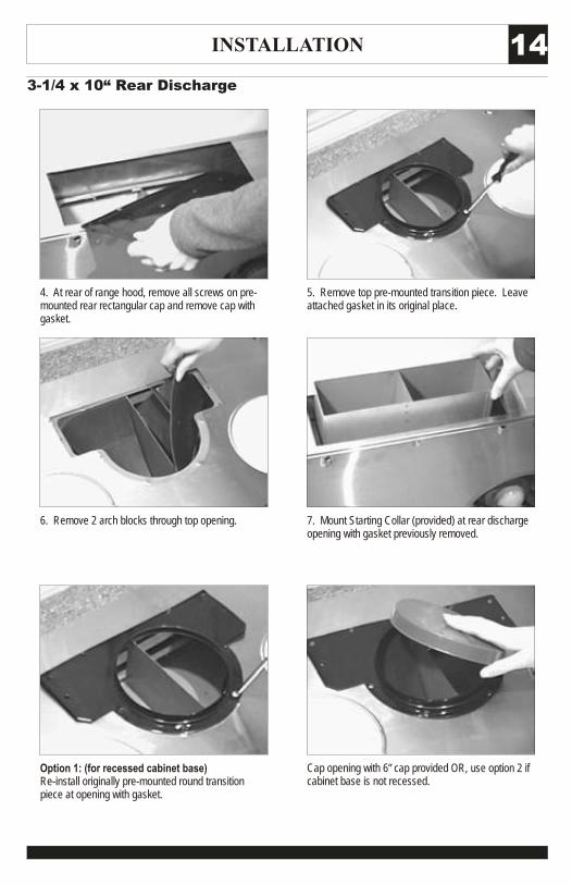
INSTALLATION 143-1/4 x 10“ Rear Discharge
4. At rear of range hood, remove all screws on pre-mounted rear rectangular cap and remove cap with gasket.
6. Remove 2 arch blocks through top opening.
Option 1: (for recessed cabinet base)Re-install originally pre-mounted round transition piece at opening with gasket.
7. Mount Starting Collar (provided) at rear discharge opening with gasket previously removed.
Cap opening with 6“ cap provided OR, use option 2 if cabinet base is not recessed.
5. Remove top pre-mounted transition piece. Leave attached gasket in its original place.
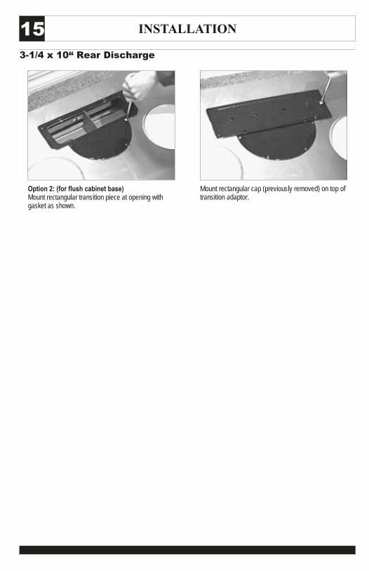
INSTALLATION153-1/4 x 10“ Rear Discharge
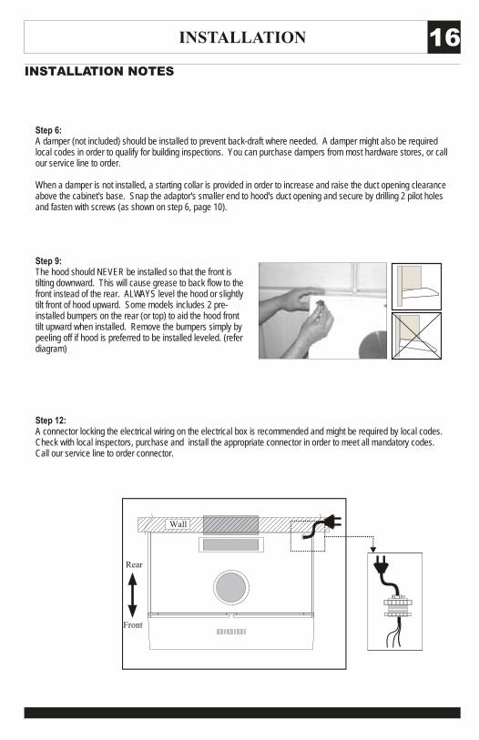
Option 2: (for flush cabinet base)Mount rectangular transition piece at opening with gasket as shown.
Mount rectangular cap (previously removed) on top of transition adaptor.
INSTALLATION 16INSTALLATION NOTES
Step 6: A damper (not included) should be installed to prevent back-draft where needed. A damper might also be required local codes in order to qualify for building inspections. You can purchase dampers from most hardware stores, or call our service line to order.
When a damper is not installed, a starting collar is provided in order to increase and raise the duct opening clearance above the cabinet's base. Snap the adaptor's smaller end to hood's duct opening and secure by drilling 2 pilot holes and fasten with screws (as shown on step 6, page 10).
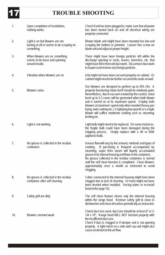
Step 9: The hood should NEVER be installed so that the front is tilting downward. This will cause grease to back flow to the front instead of the rear. ALWAYS level the hood or slightly tilt front of hood upward. Some models includes 2 pre-installed bumpers on the rear (or top) to aid the hood front tilt upward when installed. Remove the bumpers simply by peeling off if hood is preferred to be installed leveled. (refer diagram)
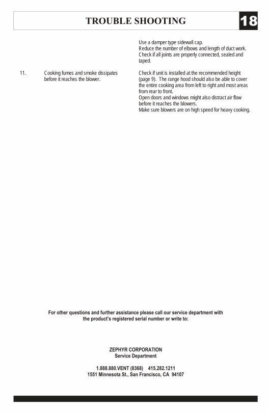
Step 12: A connector locking the electrical wiring on the electrical box is recommended and might be required by local codes. Check with local inspectors, purchase and install the appropriate connector in order to meet all mandatory codes. Call our service line to order connector.
Front
Rear
Wall
TROUBLE SHOOTING17
1. Upon completion of installation, nothing works.
2. Light is on but blowers are not turning at all or seems to be scraping on something.
3. When blowers are on, something seems to be loose and spinning around inside.
4. Vibration when blowers are on
5. Blowers noise
6. Light is not working
7. No grease is collected in the residue containers
8. No grease is collected in the residue containers after self cleaning.
9. Safety grill are dirty
10. Blowers seemed weak
Check if unit has been plugged in, make sure that all power has been turned back on and all electrical wiring are properly connected.
Blower blade unit might have been mounted too low and scraping the bottom or jammed. Loosen hex screw on blade unit and adjust to proper height.
There might have been foreign particles left within the discharge opening or rocks, leaves, branches, etc. that might have fell in from old duct work. Disconnect duct work to inspect and remove any foreign particles.
Unit might not have been secured properly on cabinet. Or cabinet might need to be further secured into studs on wall.
Our blowers are designed to perform up to 695 cfm. A properly functioning motor itself should be relatively quiet. Nevertheless, due to vacuum created by the suction, noise level up to 5.5 sones will be generated when both blower unit is turned on at its maximum speed. Employ both blowers at maximum speed only when needed (heavy pan frying, wok cooking etc.) Employing low speeds or a single blower will suffice moderate cooking such as steaming, broiling etc.
Light bulb might need to be replaced. On some instances, the fragile bulb could have been damaged during the shipping process. Simply replace with a 40 or 60W appliance bulb.
Grease flow will vary by the amount, methods and types of cooking. If pan-frying is frequent accompanied by steaming, vapor from steam will liquefy accumulated grease in its internal housing and flows in the containers.No grease collected in the residue containers is normal until the self clean function is completed. Clean blowers approximately once a month as instructed to avoid clogging.
Tubes connected to the internal housing might have been clogged due to lack of cleaning. Or hood might not have been leveled when installed. Unclog tubes or re-install hood (refer page 16).
The self clean feature cleans only the internal housing within the range hood. Remove safety grill to clean in dishwasher and clean all surface periodically as instructed.
Check duct size used, duct size should be at least 6“ or 3-1/4 x 10”. Range hood WILL NOT function properly with the insufficient duct size.Check if duct is clogged or if damper unit is not opening properly. A tight mesh on a side wall cap unit might also cause restriction to the air flow.
TROUBLE SHOOTING 18
11. Cooking fumes and smoke dissipates before it reaches the blower.
Use a damper type sidewall cap.Reduce the number of elbows and length of duct work.Check if all joints are properly connected, sealed and taped.
Check if unit is installed at the recommended height (page 9). The range hood should also be able to cover the entire cooking area from left to right and most areas from rear to front.Open doors and windows might also distract air flow before it reaches the blowers.Make sure blowers are on high speed for heavy cooking.
For other questions and further assistance please call our service department with the product’s registered serial number or write to:
ZEPHYR CORPORATION Service Department
1.888.880.VENT (8368) 415.282.12111551 Minnesota St., San Francisco, CA 94107
www.zephyronline.comW
arra
nty
One Year Service Repair Warranty:For one year from date of original purchase, we will provide free of charge, service labor to repair any failed parts or components due to manufacturing defects.
Ten Years Parts Warranty:For ten years from date of original purchase, we will provide free of charge, nonconsumable replacement parts or components that failed due to manufacturing defects. Consumable parts not covered by this warranty include: Light Bulbs,
Metal and Charcoal Filters.
Who is Covered:This warranty is extended to the original purchaser for products purchased for ordinary home use in the 48 mainland states,Hawaii and Washington D.C. In Canada and Alaska, this warranty is Limited. There might be costs associated with shipping the products to our designated service locations or you might need to pay service technician's travel costs, to havethe appliance repaired in-home.
This Warranty will be Voided when:Product damaged through negligence, misuse, abuse, accident. Improper installation and failure to follow installation instruc-tions. When product is used commercially or other than its intended purpose. Damaged because of improper connection withequipment of other manufacturers. Repaired or modified by anyone other than Zephyr's Authorized Agents.
What is Not Covered:Consumable parts such as light bulbs, filters, and fuses. Services outside of service area and the labor cost incurred in connection with the removal, shipping and reinstallation cost, nor does it cover any other contingent expenses. The naturalwear of finish, and wear due to improper maintenance, use of corrosive and abrasive cleaning products, pads, and oven cleaner products. Chips, dents or cracks due to abuse, misuse, freight damage, or improper installation. Service trips to yourhome to teach you how to use the product. Damage of product caused by accident, fire, floods or act of God.
This warranty is valid in the United States and Canada. It is non-transferable and applies only to the original purchaser and does not extend to subsequent owners of this product. Any applicable implied waranties, including the warranty ofmerchantability, are limited in duration to a period of express warranty as provided herein beginning with the date of original purchase at retail and, no warranties, whether express or implied, shall apply to this product thereafter.
Have your product proof of purchase with date ready for warranty issues. Or write to:
Zephyr CorporationService and Warranty Department395 Mendell StreetSan Francisco, CA 94124
TO OBTAIN SERVICE UNDER WARRANTY: You must present proof of original purchase date. Please keep a copy of your dated proof of purchase (sales slip) in order to obtain service under warranty.
TO OBTAIN SERVICE UNDER WARRANTYor any Service Related Questions, please call:1-888-880-8368
Staple your receipt here.Proof of the original purchase
date is needed to obtain serviceunder the warranty.
JAN07.0101