Embed Size (px)
Citation preview
Use and maintenance manual
John Deere Electronically – Controlled
POWERTECH 4.5 L & 6.8 L
4045 and 6068 OEM Diesel Engines
CALIFORNIA Proposition 65 Warning
Diesel engine exhaust and some of its constituents are known to the State of California to cause cancer, birth
defects, and other reproductive harm.
If this product contains a gasoline engine:
WARNING
The engine exhaust from this product contains chemicals known to the State of California to cause cancer, birth
defects or other reproductive harm.
The State of California requires the above two warnings.
Réf. constructeur : OMRG33324
Réf. GPAO : 33522045801 ind2
https://www.truck-manuals.net/

https://www.truck-manuals.net/
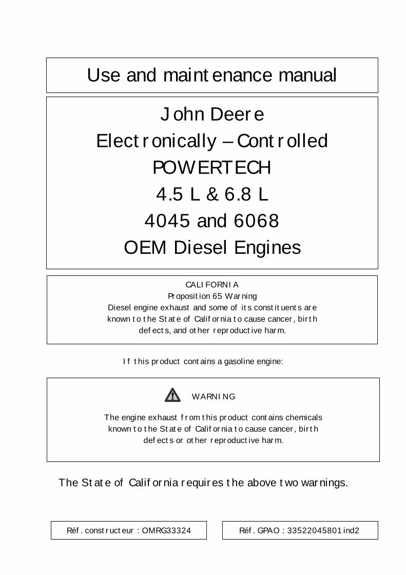
Danger
Warning about the dangers linked to fuel discharges under high pressure on engines equipped with Denso high pressure common rail (HPCR). Watch out for fuel under high pressure throughout the system Never dismantle the fuel lines, when the engine is running (lines under high pressure) It is better to work on the injection system when the fuel temperature is less than 30°C Wait at least 5 minutes after the engine stops before carrying out work on the injection system (check the pressure before doing anything) After changing the component, check that there are no fuel leaks. Carry out this test with the engine protection closed (engine bonnet or other protection) Do not dismantle and reassemble the injector parts
https://www.truck-manuals.net/
Introduction
OURGP11,000021C –19–15OCT03–1/2
Foreword
THIS MANUAL CONTAINS INFORMATION to operateand service the following Tier 2 emission-certified1
engines:
Saran-built (France) Tier 2 Mechanically ControlledEngines:
• CD4045DF270• CD4045TF270
Saran-built (France) Tier 2 Electronically ControlledEngines:
• CD4045TF275 (DE10 Fuel System)• CD4045HF275 (DE10 Fuel System)• CD4045HF475 (HPCR System; 4-Valve Head)• CD6068TF275 (DE10 Fuel System)• CD6068HF275 (DE10/VP44 Fuel System)• CD6068HF475 (HPCR System; 4-Valve Head)
Torreon-built (Mexico) Tier 2 Mechanically ControlledEngines:
• PE4045DF270• PE4045TF270
Torreon-built (Mexico) Tier 2 Electronically ControlledEngines:
• PE4045TF275 (DE10 Fuel System)• PE4045HF275 (DE10 Fuel System)• PE4045HF475 (HPCR System; 4-Valve Head)• PE6068TF275 (DE10 Fuel System)• PE6068HF275 (DE10/VP44 Fuel System)
• PE6068HF475 (HPCR System; 4-Valve Head)
READ THIS MANUAL carefully to learn how to operateand service your engine correctly. Failure to do socould result in personal injury or equipment damage.
THIS MANUAL SHOULD BE CONSIDERED apermanent part of your engine and should remain withthe engine when you sell it.
MEASUREMENTS IN THIS MANUAL are given in bothmetric and customary U.S. unit equivalents. Use onlycorrect replacement parts and fasteners. Metric andinch fasteners may require a specific metric or inchwrench.
WRITE ENGINE SERIAL NUMBERS and option codesin the spaces indicated in the Record Keeping Section.Accurately record all the numbers. Your dealer alsoneeds these numbers when you order parts. File theidentification numbers in a secure place off the engine.
SETTING FUEL DELIVERY beyond published factoryspecifications or otherwise overpowering will result inloss of warranty protection for this engine.
CERTAIN ENGINE ACCESSORIES such as radiator,air cleaner, and instruments are optional equipment onJohn Deere OEM Engines. These accessories may beprovided by the equipment manufacturer instead ofJohn Deere. This operator’s manual applies only to theengine and those options available through the JohnDeere distribution network.
1Emission certified for United States as EPA Tier 2 and for EuropeanUnion as Stage II.
021604
PN=2
https://www.truck-manuals.net/
Introduction
OURGP11,000021C –19–15OCT03–2/2
IMPORTANT: This manual covers onlyPOWERTECH Tier 2 emission certified4.5 and 6.8 L OEM engines listed.These engines meet Tier 2 emissioncertification standards. 2 (This is forboth the U.S. EPA and EuropeanUnion Council (EU) standards.)Engines with mechanical controlswhich are non-emission certified orTier 1 emission certified (U.S. and
EU) are covered in a separateoperators manual, OMRG25204.
NOTE: This manual covers engines provided to OEM(Outside Equipment Manufacturers). Forengines in Deere machines, refer to themachine operator’s manual. All Tier 2 enginesbuilt in Saran (CD prefix) are serial number(800,000 - )
2Two exceptions: The 4045HF475 and 6068HF475 for generatorapplications at 1500 rpm are still emission non-certified.
021604
PN=3
https://www.truck-manuals.net/

Introduction
021604
PN=4
https://www.truck-manuals.net/
Introduction
OURGP11,0000251 –19–06NOV03–1/1
Engine Owner
John Deere Engine Owner:
Don’t wait until you need warranty or other service tomeet your local John Deere Engine Distributor orService Dealer. To register your engine for warrantyvia the Internet, use the following URL:http://www.johndeere.com/enginewarranty
Learn who your dealer is and where he is. At your firstconvenience, go meet him. He’ll want to get to knowyou and to learn what your needs might be.
Aux Utilisateurs De Moteurs John Deere:
N’attendez pas d’etre oblige d’avoir recours a votreconcessionnaire John Deere ou au point de service leplus proche pour vous adresser a lui. Pour enregistrervotre moteur pour la garantie via Internet, utilisezl’adresse suivante:http://www.johndeere.com/enginewarranty
Renseignez-vous des que possible pour l’identifier etle localiser. A la premiere occasion, prenez contactavec lui et faites-vous connaıtre. Il sera lui aussiheureux de faire votre connaissance et de vousproposer ses services le moment venu.
An Den Besitzer Des John Deere Motors:
Warten Sie nicht auf einen evt. Reparaturfall, um dennachstgelegenen John Deere Handler kennen zulernen. Zur Registrierung Ihres Motors fur die Garantiedient folgende Internet-Adresse:http://www.johndeere.com/enginewarranty
Machen Sie sich bei ihm bekannt und nutzen Sie sein“Service Angebot”.
Proprietario del motore John Deere:
Non aspetti fino al momento di far valere la garanzia odi chiedere assistenza per fare la conoscenza del
distributore dei motori John Deere o delconcessionario che fornisce l’assistenza tecnica. Perregistrare via Internet la garanzia del suo motore, sicollegi al seguente sito URL:http://www.johndeere.com/enginewarranty
Lo identifichi e si informi sulla sua ubicazione. Allaprima occasione utile lo contatti. Egli desidera fare lasua conoscenza e capire quali potrebbero essere lesue necessita.
Propietario De Equipo John Deere:
No espere hasta necesitar servicio de garantıa o deotro tipo para conocer a su Distribuidor de MotoresJohn Deere o al Concesionario de Servicio. Registresu motor para la garantıa en la siguiente direccion deinternet: http://www.johndeere.com/enginewarranty
Enterese de quien es, y donde esta situado. Cuandotenga un momento, vaya a visitarlo. A el le gustaraconocerlo, y saber cuales podrıan ser susnecesidades.
Till a gare av John Deere motorer:
Ta reda pa vem din aterforsaljare ar och besok honomsa snart tillfalle ges. Vanta inte tills det ar dags forservice eller eventuellt garantiarbete. Din motorgarantiregistrerar Du via Internet pahttp://www.johndeere.com/enginewarranty
Din aterforsaljare vill mycket garna traffa dig for att larakanna dina behov och hur bast han kan hjalpa dig.
021604
PN=5
https://www.truck-manuals.net/
Introduction
OUOD002,0000162 –19–25FEB03–1/1
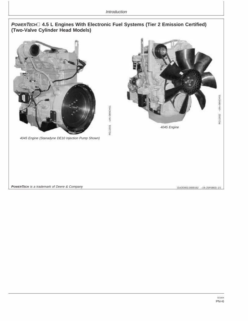
POWERTECH 4.5 L Engines With Electronic Fuel Systems (Tier 2 Emission Certified)(Two-Valve Cylinder Head Models)
RG
1193
1–U
N–0
6NO
V01
4045 Engine (Stanadyne DE10 Injection Pump Shown)
RG
1193
2–U
N–0
6NO
V01
4045 Engine
POWERTECH is a trademark of Deere & Company
021604
PN=6
https://www.truck-manuals.net/
Introduction
OUOD002,0000163 –19–25FEB03–1/1
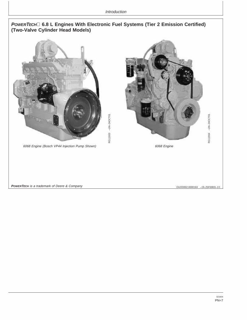
POWERTECH 6.8 L Engines With Electronic Fuel Systems (Tier 2 Emission Certified)(Two-Valve Cylinder Head Models)
RG
1193
3–U
N–2
4OC
T01
6068 Engine (Bosch VP44 Injection Pump Shown)
RG
1193
4–U
N–2
4OC
T01
6068 Engine
POWERTECH is a trademark of Deere & Company
021604
PN=7
https://www.truck-manuals.net/
Introduction
OURGP11,000018B –19–12FEB04–1/1
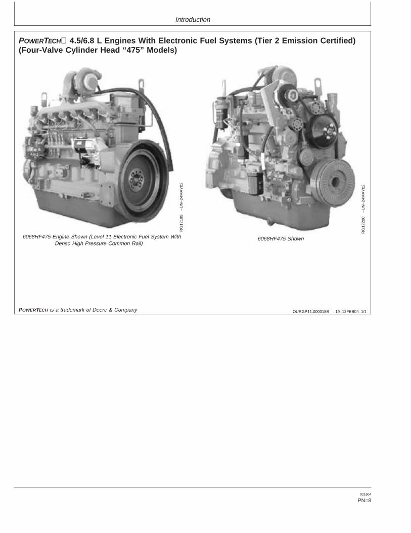
POWERTECH 4.5/6.8 L Engines With Electronic Fuel Systems (Tier 2 Emission Certified)(Four-Valve Cylinder Head “475” Models)
RG
1219
9–U
N–2
4MA
Y02
6068HF475 Engine Shown (Level 11 Electronic Fuel System WithDenso High Pressure Common Rail)
RG
1220
0–U
N–2
4MA
Y02
6068HF475 Shown
POWERTECH is a trademark of Deere & Company
021604
PN=8
https://www.truck-manuals.net/
ContentsPage Page
Record Keeping Viewing Engine Configuration Data . . . . . . . . . 16-14PowerTech Medallion . . . . . . . . . . . . . . . . . . . . . 01-1 Viewing Active Engine ServiceEngine Serial Number Plate . . . . . . . . . . . . . . . . 01-1 Codes/Diagnostic Trouble Codes (DTCs) . . . 16-16Record Engine Serial Number . . . . . . . . . . . . . . 01-2 Viewing Stored ServiceEngine Option Codes . . . . . . . . . . . . . . . . . . . . . 01-3 Codes/Diagnostic Trouble CodesRecord Fuel Injection Pump Model Number . . . . 01-5 (DTCs) in the Engine ECU . . . . . . . . . . . . . . 16-17
Instrument Panel - Elect. Cont. Later EnginesSafety . . . . . . . . . . . . . . . . . . . . . . . . . . . . . . . . 05-1Instrument Panels. . . . . . . . . . . . . . . . . . . . . . . . 17-1Using Diagnostic Gauge to Access EngineFuels, Lubricants, and Coolant
Information . . . . . . . . . . . . . . . . . . . . . . . . . . . 17-4Diesel Fuel . . . . . . . . . . . . . . . . . . . . . . . . . . . . . 10-1Main Menu Navigation . . . . . . . . . . . . . . . . . . . . 17-5Lubricity of Diesel Fuel . . . . . . . . . . . . . . . . . . . . 10-1Engine Configuration Data . . . . . . . . . . . . . . . . . 17-6Handling and Storing Diesel Fuel . . . . . . . . . . . . 10-2Accessing Stored Trouble Codes . . . . . . . . . . . . 17-8Dieselscan Fuel Analysis . . . . . . . . . . . . . . . . . . 10-2Accessing Active Trouble Codes . . . . . . . . . . . 17-10Bio-Diesel Fuel . . . . . . . . . . . . . . . . . . . . . . . . . . 10-3Engine Shutdown Codes . . . . . . . . . . . . . . . . . 17-12Minimizing the Effect of Cold Weather onAdjusting Backlighting. . . . . . . . . . . . . . . . . . . . 17-13Diesel Engines . . . . . . . . . . . . . . . . . . . . . . . . 10-4Adjusting Contrast . . . . . . . . . . . . . . . . . . . . . . 17-15Diesel Engine Break-In Oil . . . . . . . . . . . . . . . . . 10-6Selecting Units Of Measurement . . . . . . . . . . . 17-17Diesel Engine Oil . . . . . . . . . . . . . . . . . . . . . . . . 10-7Setup 1-Up Display . . . . . . . . . . . . . . . . . . . . . 17-20Extended Diesel Engine Oil Service Intervals . . . 10-8Setup 4-Up Display . . . . . . . . . . . . . . . . . . . . . 17-26Mixing of Lubricants . . . . . . . . . . . . . . . . . . . . . . 10-8
OILSCANand COOLSCAN . . . . . . . . . . . . . . 10-9Instrument Panel - Mech. Cont. “270” EnginesAlternative and Synthetic Lubricants. . . . . . . . . . 10-9Instrument Panel (Earlier 4.5 L “270”Lubricant Storage . . . . . . . . . . . . . . . . . . . . . . . 10-10
Engines) . . . . . . . . . . . . . . . . . . . . . . . . . . . . . 18-1Grease . . . . . . . . . . . . . . . . . . . . . . . . . . . . . . . 10-10Instrument Panel (Later 4.5 L “270” Engines) . . . 18-3Diesel Engine Coolant . . . . . . . . . . . . . . . . . . . 10-11
Drain Intervals for Diesel Engine Coolant . . . . 10-12 Engine Operation - Except 4.5L “270” EnginesSupplemental Coolant Additives . . . . . . . . . . . . 10-13 Engine Break-In Service. . . . . . . . . . . . . . . . . . . 19-1Testing Diesel Engine Coolant . . . . . . . . . . . . . 10-13 Starting the Engine. . . . . . . . . . . . . . . . . . . . . . . 19-4Operating in Warm Temperature Climates . . . . 10-14 Normal Engine Operation . . . . . . . . . . . . . . . . . . 19-7Disposing of Coolant . . . . . . . . . . . . . . . . . . . . 10-14 Warming Engine. . . . . . . . . . . . . . . . . . . . . . . . . 19-8
Cold Weather Operation. . . . . . . . . . . . . . . . . . . 19-9Instrument Panel Identification Using a Booster Battery or Charger . . . . . . . . . 19-11Instrument Panels - Identification . . . . . . . . . . . . 15-1 Avoid Excessive Engine Idling . . . . . . . . . . . . . 19-12
Changing Engine Speed. . . . . . . . . . . . . . . . . . 19-13Instrument Panel - Elect. Cont. Earlier Engines Stopping The Engine . . . . . . . . . . . . . . . . . . . . 19-16Instrument Panel . . . . . . . . . . . . . . . . . . . . . . . . 16-1 Auxiliary Gear Drive Limitations . . . . . . . . . . . . 19-17Using Diagnostic Gauge to Access Engine Generator Set (Standby) Applications. . . . . . . . 19-17
Information . . . . . . . . . . . . . . . . . . . . . . . . . . . 16-8Using Touch Switches to Display Engine Operation- 4.5 L “270” Engines
Normal Engine Operation . . . . . . . . . . . . . . . . . . 20-1Information . . . . . . . . . . . . . . . . . . . . . . . . . . 16-10Changing Units of Measure (English or
Continued on next pageMetric). . . . . . . . . . . . . . . . . . . . . . . . . . . . . . 16-12
All information, illustrations and specifications in this manual are based onthe latest information available at the time of publication. The right isreserved to make changes at any time without notice.
COPYRIGHT 2004DEERE & COMPANY
Moline, IllinoisAll rights reserved
A John Deere ILLUSTRUCTION ManualPrevious Editions
Copyright 2001, 2002, 2003
i 021604
PN=1
https://www.truck-manuals.net/

Contents
Page Page
Break-In Service. . . . . . . . . . . . . . . . . . . . . . . . . 20-2 Check and Adjust Valve Clearance (AllAuxiliary Gear Drive Limitations . . . . . . . . . . . . . 20-3 Engines Except 4045HF475 AndGenerator Set (Standby) Power Units. . . . . . . . . 20-4 6068HF475) . . . . . . . . . . . . . . . . . . . . . . . . . . 35-9Starting The Engine . . . . . . . . . . . . . . . . . . . . . . 20-4 Check and Adjust Valve ClearanceCold Weather Starting . . . . . . . . . . . . . . . . . . . . 20-6 (4045HF475 And 6068HF475 Engines). . . . . 35-12Warming Engine. . . . . . . . . . . . . . . . . . . . . . . . . 20-8 Test Glow Plugs for ContinuityAvoid Excessive Engine Idling . . . . . . . . . . . . . . 20-9 (4045HF475 And 6068HF475 Engines). . . . . 35-15Stopping the Engine . . . . . . . . . . . . . . . . . . . . . 20-10Using a Booster Battery or Charger . . . . . . . . . 20-11 Service as Required
Additional Service Information . . . . . . . . . . . . . . 40-1Lubrication and Maintenance Do Not Modify Fuel System . . . . . . . . . . . . . . . . 40-2Observe Service Intervals. . . . . . . . . . . . . . . . . . 21-1 Adding Coolant. . . . . . . . . . . . . . . . . . . . . . . . . . 40-3Use Correct Fuels, Lubricants, and Coolant . . . . 21-1 Replacing Single Stage Air Cleaner . . . . . . . . . . 40-5Lubrication and Maintenance Service Replacing Axial Seal Air Cleaner Filter
Interval Chart—Standard Industrial Engines . . 21-2 Element . . . . . . . . . . . . . . . . . . . . . . . . . . . . . 40-6Lubrication and Maintenance Service Replacing Radial Seal Air Cleaner Filter
Interval Chart—Generator (Standby) Element . . . . . . . . . . . . . . . . . . . . . . . . . . . . . 40-8Applications . . . . . . . . . . . . . . . . . . . . . . . . . . 21-4 Replacing Fan and Alternator Belts . . . . . . . . . 40-10
Checking Fuses . . . . . . . . . . . . . . . . . . . . . . . . 40-11Lubrication & Maintenance/Daily Checking Air Compressors . . . . . . . . . . . . . . . . 40-11Daily Prestarting Checks . . . . . . . . . . . . . . . . . . 25-1 Bleeding the Fuel System (Engines With
Electronic Fuel Systems And Bosch VP44Lubrication & Maintenance/500 Hour/12 Month Pump) . . . . . . . . . . . . . . . . . . . . . . . . . . . . . . 40-12Servicing Fire Extinguisher . . . . . . . . . . . . . . . . . 30-1 Bleed the Fuel System (Engines withChecking Engine Mounts . . . . . . . . . . . . . . . . . . 30-1 Electronic Fuel Systems and Stanadyne DE10Servicing Battery . . . . . . . . . . . . . . . . . . . . . . . . 30-2 Pump) . . . . . . . . . . . . . . . . . . . . . . . . . . . . . . 40-14Manual Belt Tensioner Adjustment . . . . . . . . . . . 30-4 Bleed the Fuel System (Engines withManual Belt Tensioner Adjustment Using Electronic Fuel Systems and Denso High
Belt Tension Tool (Alternate Method Pressure Common Rail) (4045HF475,For Engines Without Auxiliary Drive). . . . . . . . 30-5 6068HF475) . . . . . . . . . . . . . . . . . . . . . . . . . 40-17
Changing Engine Oil and Replacing Filter . . . . . 30-7Bleed the Fuel System (4045DF270,
Checking Crankcase Vent System . . . . . . . . . . . 30-94045TF270) . . . . . . . . . . . . . . . . . . . . . . . . . 40-19
Checking Air Intake System . . . . . . . . . . . . . . . 30-11Replacing Fuel Filter Elements . . . . . . . . . . . . . 30-12
TroubleshootingChecking Belt Tensioner Spring TensionGeneral Troubleshooting Information . . . . . . . . . 45-1and Belt Wear (Automatic Tensioner) . . . . . . 30-14Precautions For Welding On EnginesChecking Engine Electrical Ground
Equipped With Electronic Engine Control UnitConnections . . . . . . . . . . . . . . . . . . . . . . . . . 30-16(ECU) . . . . . . . . . . . . . . . . . . . . . . . . . . . . . . . 45-2Checking Cooling System. . . . . . . . . . . . . . . . . 30-16
Engine Wiring Layout (Electronic FuelReplenishing Supplemental CoolantSystem With Stanadyne DE10 InjectionAdditives (SCAs) Between CoolantPump) . . . . . . . . . . . . . . . . . . . . . . . . . . . . . . . 45-3Changes . . . . . . . . . . . . . . . . . . . . . . . . . . . . 30-17
Engine Wiring Layout (Electronic FuelTesting Diesel Engine Coolant . . . . . . . . . . . . . 30-19System With Bosch VP44 Injection Pump) . . . 45-4Pressure Testing Cooling System. . . . . . . . . . . 30-20
Engine Wiring Layout (Electronic FuelChecking and Adjusting Engine Speeds . . . . . . 30-21System With Denso High Pressure CommonRail)(4045HF475,6068HF475). . . . . . . . . . . . . 45-5Lubrication & Maint./2000 Hour/24 Month
Engine Wiring Diagram (With EarlierAdjusting Variable Speed (Droop) — 4.5Electronic Instrument Panel) . . . . . . . . . . . . . . 45-6L “270” Generator Set Engines Only . . . . . . . . 35-1
Engine Wiring Diagram (Engines WithChecking Crankshaft Vibration Damper(6-Cylinder Engine Only). . . . . . . . . . . . . . . . . 35-2 Electronic Instrument Panel) . . . . . . . . . . . . . . 45-7
Flushing and Refilling Cooling System . . . . . . . . 35-3Testing Thermostats Opening Temperature . . . . 35-6 Continued on next page
ii 021604
PN=2
https://www.truck-manuals.net/
Contents
Page Page
Engine Wiring Diagram (With Later Emission System WarrantyU.S. EPA Emmission Control WarrantyFull-Featured Electronic Instrument Panel) . . . 45-8
Statement . . . . . . . . . . . . . . . . . . . . . . . . . . . . 65-1Engine Wiring Diagram (With LaterEmission Control System Certification Label. . . . 65-2Full-Featured Electronic Instrument Panel)—
Continued . . . . . . . . . . . . . . . . . . . . . . . . . . . . 45-9Engine Troubleshooting . . . . . . . . . . . . . . . . . . 45-10Blink Code Method for Retrieving
Diagnostic Trouble Codes (All ExceptEarly VP44 Pump Engines). . . . . . . . . . . . . . 45-18
Blink Code Method for RetrievingDiagnostic Trouble Codes (Early VP44Pump Engines Only) . . . . . . . . . . . . . . . . . . . 45-20
Instrument Panel Method for RetrievingDiagnostic Trouble Codes . . . . . . . . . . . . . . . 45-22
Displaying Of Diagnostic Trouble Codes(DTCs) . . . . . . . . . . . . . . . . . . . . . . . . . . . . . 45-23
Listing of Diagnostic Trouble Codes (DTCs)(Engines With Electronic FuelSystems And Stanadyne DE10 Pump) . . . . . 45-24
Listing of Diagnostic Trouble Codes (DTCs)(Engines With Electronic FuelSystems And Bosch VP44 Pump). . . . . . . . . 45-26
Listing of Diagnostic Trouble Codes (DTCs)(Engines With Electronic Fuel SystemsAnd Denso High Pressure Common Rail) (“475”Engines) . . . . . . . . . . . . . . . . . . . . . . . . . . . . 45-28
Error Codes Displayed (With EarlyElectronic Panels) . . . . . . . . . . . . . . . . . . . . . 45-30
Intermittent Fault Diagnostics (WithElectronic Controls). . . . . . . . . . . . . . . . . . . . 45-31
Displaying Diagnostic Gauge Software(Later Engines) . . . . . . . . . . . . . . . . . . . . . . . 45-31
StorageEngine Storage Guidelines . . . . . . . . . . . . . . . . . 50-1Preparing Engine for Long Term Storage . . . . . . 50-2Removing Engine from Long Term Storage . . . . 50-3
SpecificationsGeneral OEM Engine Specifications. . . . . . . . . . 55-1Engine Power Ratings And Fuel System
Specifications . . . . . . . . . . . . . . . . . . . . . . . . . 55-3Engine Crankcase Oil Fill Quantities . . . . . . . . . 55-6Unified Inch Bolt and Screw Torque Values . . . . 55-7Metric Bolt and Screw Torque Values. . . . . . . . . 55-8
Lubrication and Maintenance RecordsUsing Lubrication and Maintenance Records . . . 60-1Daily (Prestarting) Service . . . . . . . . . . . . . . . . . 60-1500 Hour/12 Month Service . . . . . . . . . . . . . . . . 60-22000 Hour/24 Month Service . . . . . . . . . . . . . . . 60-3Service as Required . . . . . . . . . . . . . . . . . . . . . . 60-4
iii 021604
PN=3
https://www.truck-manuals.net/

Contents
iv 021604
PN=4
https://www.truck-manuals.net/
Record Keeping
OURGP11,0000274 –19–24NOV03–1/1
POWERTECH Medallion
RG
1160
8–U
N–1
7OC
T01
RG
1160
9–U
N–1
7OC
T01
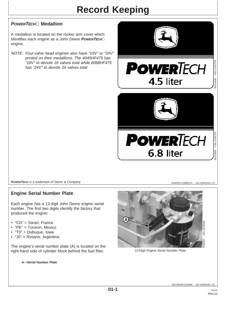
A medallion is located on the rocker arm cover whichidentifies each engine as a John Deere POWERTECHengine.
NOTE: Four-valve head engines also have “16V” or “24V”printed on their medallions. The 4045HF475 has“16V” to denote 16 valves total while 6068HF475has “24V” to denote 24 valves total.
POWERTECH is a trademark of Deere & Company.
RG,RG34710,5506 –19–10NOV01–1/1
Engine Serial Number Plate
RG
8007
–UN
–15J
AN
99
13-Digit Engine Serial Number Plate
A—Serial Number Plate
Each engine has a 13-digit John Deere engine serialnumber. The first two digits identify the factory thatproduced the engine:
• “CD” = Saran, France• “PE” = Torreon, Mexico• “T0” = Dubuque, Iowa• “J0” = Rosario, Argentina
The engine’s serial number plate (A) is located on theright-hand side of cylinder block behind the fuel filter.
01-1 021604
PN=11
https://www.truck-manuals.net/
Record Keeping
RG,RG34710,5507 –19–10NOV01–1/1
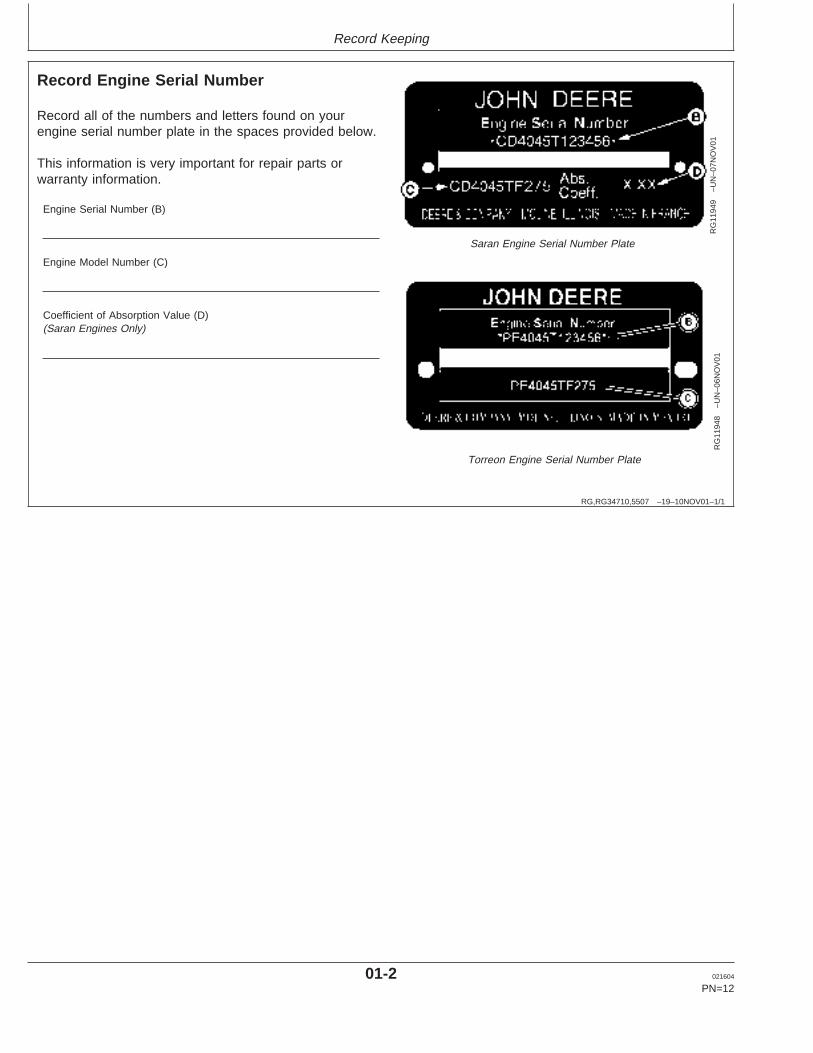
Record Engine Serial Number
RG
1194
9–U
N–0
7NO
V01
Saran Engine Serial Number Plate
RG
1194
8–U
N–0
6NO
V01
Torreon Engine Serial Number Plate
Record all of the numbers and letters found on yourengine serial number plate in the spaces provided below.
This information is very important for repair parts orwarranty information.
Engine Serial Number (B)
Engine Model Number (C)
Coefficient of Absorption Value (D)(Saran Engines Only)
01-2 021604
PN=12
https://www.truck-manuals.net/
Record Keeping
RG,RG34710,5508 –19–05MAR03–1/2
Engine Option Codes
RG
1194
6–U
N–0
6NO
V01
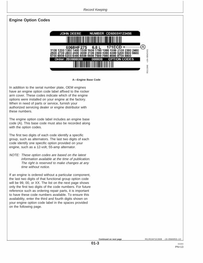
A—Engine Base Code
In addition to the serial number plate, OEM engineshave an engine option code label affixed to the rockerarm cover. These codes indicate which of the engineoptions were installed on your engine at the factory.When in need of parts or service, furnish yourauthorized servicing dealer or engine distributor withthese numbers.
The engine option code label includes an engine basecode (A). This base code must also be recorded alongwith the option codes.
The first two digits of each code identify a specificgroup, such as alternators. The last two digits of eachcode identify one specific option provided on yourengine, such as a 12-volt, 55-amp alternator.
NOTE: These option codes are based on the latestinformation available at the time of publication.The right is reserved to make changes at anytime without notice.
If an engine is ordered without a particular component,the last two digits of that functional group option codewill be 99, 00, or XX. The list on the next page showsonly the first two digits of the code numbers. For futurereference such as ordering repair parts, it is importantto have these code numbers available. To ensure thisavailability, enter the third and fourth digits shown onyour engine option code label in the spaces providedon the following page.
01-3 021604
PN=13
Continued on next page
https://www.truck-manuals.net/
Record Keeping
RG,RG34710,5508 –19–05MAR03–2/2
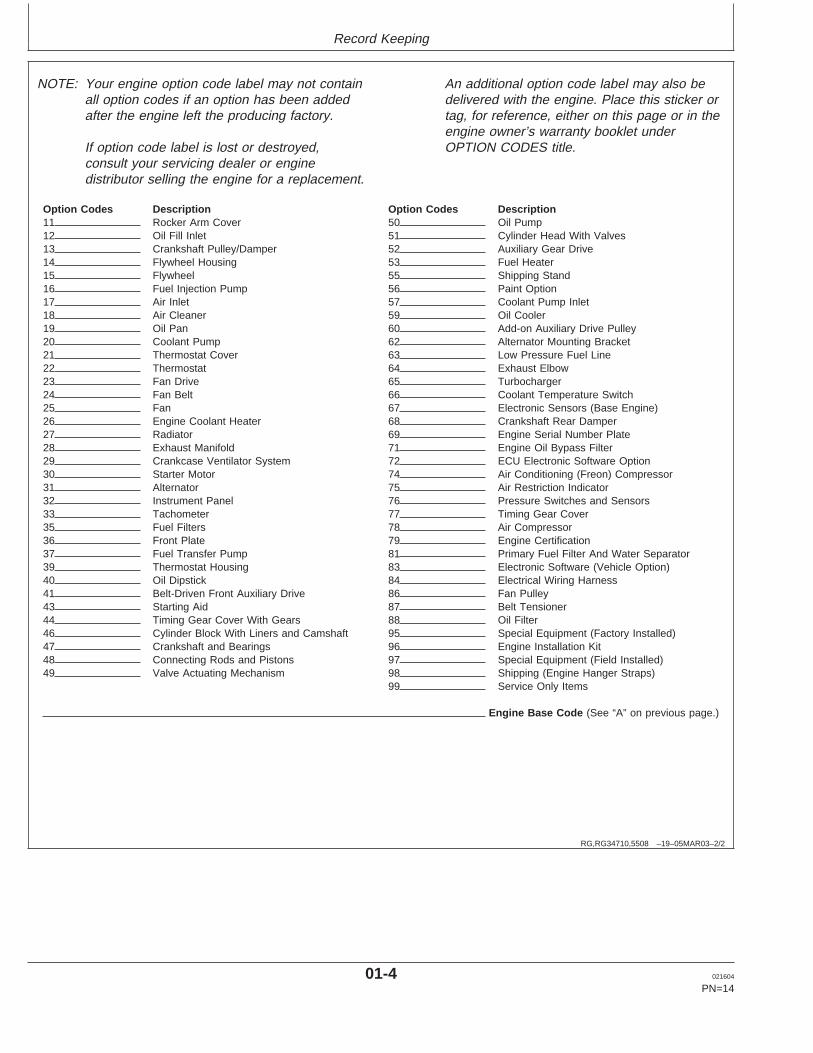
NOTE: Your engine option code label may not containall option codes if an option has been addedafter the engine left the producing factory.
If option code label is lost or destroyed,consult your servicing dealer or enginedistributor selling the engine for a replacement.
An additional option code label may also bedelivered with the engine. Place this sticker ortag, for reference, either on this page or in theengine owner’s warranty booklet underOPTION CODES title.
Option Codes Description Option Codes Description11 Rocker Arm Cover 50 Oil Pump12 Oil Fill Inlet 51 Cylinder Head With Valves13 Crankshaft Pulley/Damper 52 Auxiliary Gear Drive14 Flywheel Housing 53 Fuel Heater15 Flywheel 55 Shipping Stand16 Fuel Injection Pump 56 Paint Option17 Air Inlet 57 Coolant Pump Inlet18 Air Cleaner 59 Oil Cooler19 Oil Pan 60 Add-on Auxiliary Drive Pulley20 Coolant Pump 62 Alternator Mounting Bracket21 Thermostat Cover 63 Low Pressure Fuel Line22 Thermostat 64 Exhaust Elbow23 Fan Drive 65 Turbocharger24 Fan Belt 66 Coolant Temperature Switch25 Fan 67 Electronic Sensors (Base Engine)26 Engine Coolant Heater 68 Crankshaft Rear Damper27 Radiator 69 Engine Serial Number Plate28 Exhaust Manifold 71 Engine Oil Bypass Filter29 Crankcase Ventilator System 72 ECU Electronic Software Option30 Starter Motor 74 Air Conditioning (Freon) Compressor31 Alternator 75 Air Restriction Indicator32 Instrument Panel 76 Pressure Switches and Sensors33 Tachometer 77 Timing Gear Cover35 Fuel Filters 78 Air Compressor36 Front Plate 79 Engine Certification37 Fuel Transfer Pump 81 Primary Fuel Filter And Water Separator39 Thermostat Housing 83 Electronic Software (Vehicle Option)40 Oil Dipstick 84 Electrical Wiring Harness41 Belt-Driven Front Auxiliary Drive 86 Fan Pulley43 Starting Aid 87 Belt Tensioner44 Timing Gear Cover With Gears 88 Oil Filter46 Cylinder Block With Liners and Camshaft 95 Special Equipment (Factory Installed)47 Crankshaft and Bearings 96 Engine Installation Kit48 Connecting Rods and Pistons 97 Special Equipment (Field Installed)49 Valve Actuating Mechanism 98 Shipping (Engine Hanger Straps)
99 Service Only Items
Engine Base Code (See “A” on previous page.)
01-4 021604
PN=14
https://www.truck-manuals.net/
Record Keeping
RG,RG34710,5511 –19–10NOV01–1/1
Record Fuel Injection Pump Model Number
RG
1194
3–U
N–0
6NO
V01
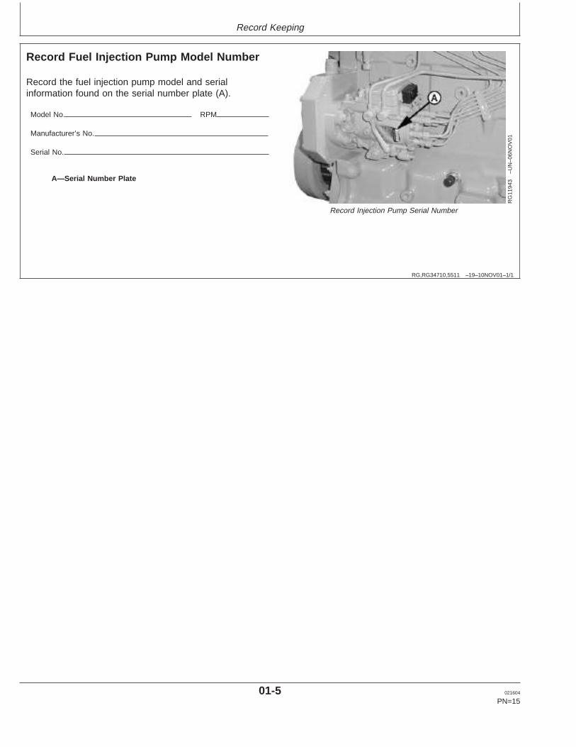
Record Injection Pump Serial Number
A—Serial Number Plate
Record the fuel injection pump model and serialinformation found on the serial number plate (A).
Model No. RPM
Manufacturer’s No.
Serial No.
01-5 021604
PN=15
https://www.truck-manuals.net/
Safety
DX,ALERT –19–29SEP98–1/1
Recognize Safety Information
T81
389
–UN
–07D
EC
88
Safety-alert symbol
This is a safety-alert symbol. When you see this symbolon your machine or in this manual, be alert to thepotential for personal injury.
Follow recommended precautions and safe operatingpractices.
DX,SIGNAL –19–03MAR93–1/1
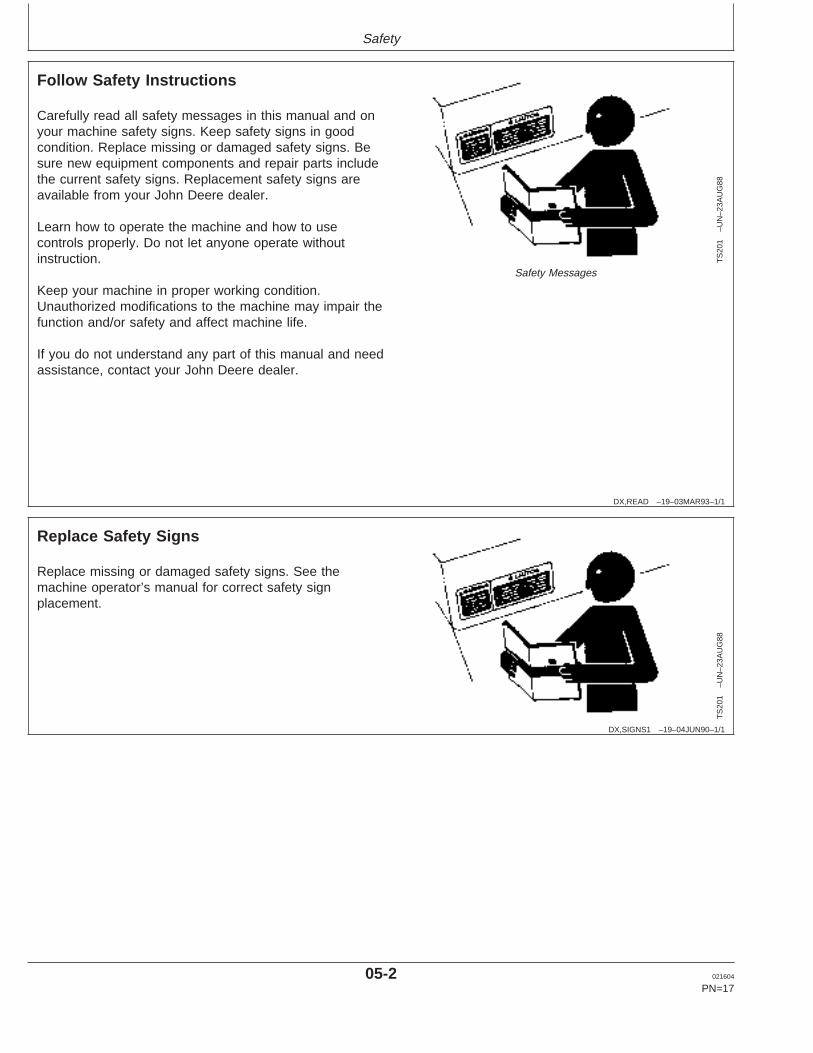
Understand Signal Words
TS
187
–19–
30S
EP
88
Signal Words
A signal word—DANGER, WARNING, or CAUTION—isused with the safety-alert symbol. DANGER identifies themost serious hazards.
DANGER or WARNING safety signs are located nearspecific hazards. General precautions are listed onCAUTION safety signs. CAUTION also calls attention tosafety messages in this manual.
05-1 021604
PN=16
https://www.truck-manuals.net/
Safety
DX,READ –19–03MAR93–1/1
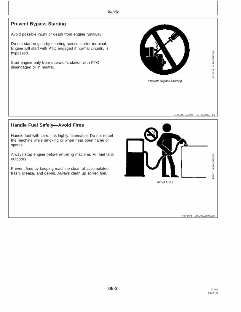
Follow Safety Instructions
TS
201
–UN
–23A
UG
88
Safety Messages
Carefully read all safety messages in this manual and onyour machine safety signs. Keep safety signs in goodcondition. Replace missing or damaged safety signs. Besure new equipment components and repair parts includethe current safety signs. Replacement safety signs areavailable from your John Deere dealer.
Learn how to operate the machine and how to usecontrols properly. Do not let anyone operate withoutinstruction.
Keep your machine in proper working condition.Unauthorized modifications to the machine may impair thefunction and/or safety and affect machine life.
If you do not understand any part of this manual and needassistance, contact your John Deere dealer.
DX,SIGNS1 –19–04JUN90–1/1
Replace Safety Signs
TS
201
–UN
–23A
UG
88
Replace missing or damaged safety signs. See themachine operator’s manual for correct safety signplacement.
05-2 021604
PN=17
https://www.truck-manuals.net/
Safety
RG,RG34710,7508 –19–30JUN97–1/1
Prevent Bypass Starting
RG
5419
–UN
–28F
EB
89
Prevent Bypass Starting
Avoid possible injury or death from engine runaway.
Do not start engine by shorting across starter terminal.Engine will start with PTO engaged if normal circuitry isbypassed.
Start engine only from operator’s station with PTOdisengaged or in neutral.
DX,FIRE1 –19–03MAR93–1/1
Handle Fuel Safely—Avoid Fires
TS
202
–UN
–23A
UG
88
Avoid Fires
Handle fuel with care: it is highly flammable. Do not refuelthe machine while smoking or when near open flame orsparks.
Always stop engine before refueling machine. Fill fuel tankoutdoors.
Prevent fires by keeping machine clean of accumulatedtrash, grease, and debris. Always clean up spilled fuel.
05-3 021604
PN=18
https://www.truck-manuals.net/
Safety
DX,FIRE2 –19–03MAR93–1/1
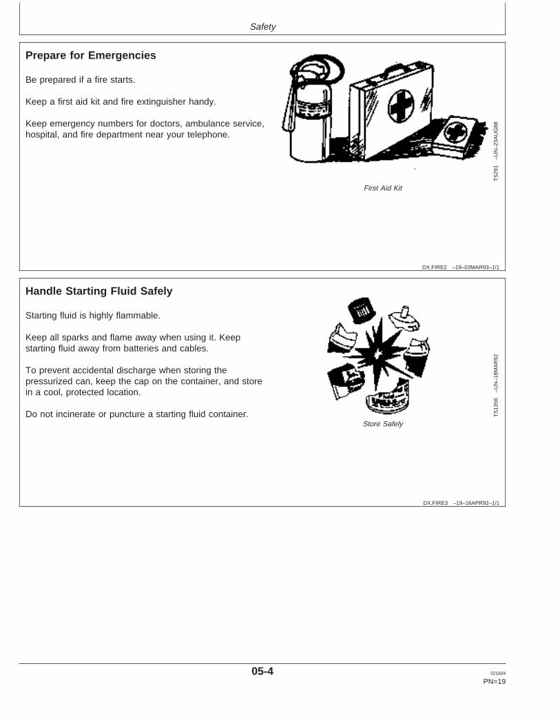
Prepare for Emergencies
TS
291
–UN
–23A
UG
88
First Aid Kit
Be prepared if a fire starts.
Keep a first aid kit and fire extinguisher handy.
Keep emergency numbers for doctors, ambulance service,hospital, and fire department near your telephone.
DX,FIRE3 –19–16APR92–1/1
Handle Starting Fluid Safely
TS
1356
–UN
–18M
AR
92
Store Safely
Starting fluid is highly flammable.
Keep all sparks and flame away when using it. Keepstarting fluid away from batteries and cables.
To prevent accidental discharge when storing thepressurized can, keep the cap on the container, and storein a cool, protected location.
Do not incinerate or puncture a starting fluid container.
05-4 021604
PN=19
https://www.truck-manuals.net/
Safety
DX,FLAME –19–29SEP98–1/1
Handle Fluids Safely—Avoid Fires
TS
227
–UN
–23A
UG
88
Avoid Fires
When you work around fuel, do not smoke or work nearheaters or other fire hazards.
Store flammable fluids away from fire hazards. Do notincinerate or puncture pressurized containers.
Make sure machine is clean of trash, grease, and debris.
Do not store oily rags; they can ignite and burnspontaneously.
OURGP12,00001DA –19–25FEB03–1/1
Service Engines Safely
TS
228
–UN
–23A
UG
88
Moving Parts
Tie long hair behind your head. Do not wear a necktie,scarf, loose clothing, or necklace when you work nearmachine tools or moving parts. If these items were to getcaught, severe injury could result.
Remove rings and other jewelry to prevent electricalshorts and entanglement in moving parts.
05-5 021604
PN=20
https://www.truck-manuals.net/
Safety
DX,WEAR –19–10SEP90–1/1
Wear Protective Clothing
TS
206
–UN
–23A
UG
88
Protective Clothing
Wear close fitting clothing and safety equipmentappropriate to the job.
Prolonged exposure to loud noise can cause impairmentor loss of hearing.
Wear a suitable hearing protective device such asearmuffs or earplugs to protect against objectionable oruncomfortable loud noises.
Operating equipment safely requires the full attention ofthe operator. Do not wear radio or music headphoneswhile operating machine.
DX,NOISE –19–03MAR93–1/1
Protect Against Noise
TS
207
–UN
–23A
UG
88
Noise Exposure
Prolonged exposure to loud noise can cause impairmentor loss of hearing.
Wear a suitable hearing protective device such asearmuffs or earplugs to protect against objectionable oruncomfortable loud noises.
05-6 021604
PN=21
https://www.truck-manuals.net/
Safety
DX,MSDS,NA –19–03MAR93–1/1
Handle Chemical Products Safely
TS
1132
–UN
–26N
OV
90
Material Safety Data Sheet
Direct exposure to hazardous chemicals can causeserious injury. Potentially hazardous chemicals used withJohn Deere equipment include such items as lubricants,coolants, paints, and adhesives.
A Material Safety Data Sheet (MSDS) provides specificdetails on chemical products: physical and health hazards,safety procedures, and emergency response techniques.
Check the MSDS before you start any job using ahazardous chemical. That way you will know exactly whatthe risks are and how to do the job safely. Then followprocedures and recommended equipment.
(See your John Deere dealer for MSDS’s on chemicalproducts used with John Deere equipment.)
DX,PTO –19–12SEP95–1/1
Stay Clear of Rotating Drivelines
TS
1644
–UN
–22A
UG
95Rotating Drivelines
Entanglement in rotating driveline can cause serious injuryor death.
Keep tractor master shield and driveline shields in placeat all times. Make sure rotating shields turn freely.
Wear close fitting clothing. Stop the engine and be surePTO driveline is stopped before making adjustments,connections, or cleaning out PTO driven equipment.
05-7 021604
PN=22
https://www.truck-manuals.net/
Safety
DX,SERV –19–17FEB99–1/1
Practice Safe Maintenance
TS
218
–UN
–23A
UG
88
Keep Area Clean
Understand service procedure before doing work. Keeparea clean and dry.
Never lubricate, service, or adjust machine while it ismoving. Keep hands, feet , and clothing frompower-driven parts. Disengage all power and operatecontrols to relieve pressure. Lower equipment to theground. Stop the engine. Remove the key. Allow machineto cool.
Securely support any machine elements that must beraised for service work.
Keep all parts in good condition and properly installed. Fixdamage immediately. Replace worn or broken parts.Remove any buildup of grease, oil, or debris.
On self-propelled equipment, disconnect battery groundcable (-) before making adjustments on electrical systemsor welding on machine.
On towed implements, disconnect wiring harnesses fromtractor before servicing electrical system components orwelding on machine.
DX,AIR –19–17FEB99–1/1
Work In Ventilated Area
TS
220
–UN
–23A
UG
88
Engine exhaust fumes
Engine exhaust fumes can cause sickness or death. If it isnecessary to run an engine in an enclosed area, removethe exhaust fumes from the area with an exhaust pipeextension.
If you do not have an exhaust pipe extension, open thedoors and get outside air into the area
05-8 021604
PN=23
https://www.truck-manuals.net/

Safety
DX,FLUID –19–03MAR93–1/1
Avoid High-Pressure Fluids
X98
11–U
N–2
3AU
G88
High-Pressure Fluids
Escaping fluid under pressure can penetrate the skincausing serious injury.
Avoid the hazard by relieving pressure beforedisconnecting hydraulic or other lines. Tighten allconnections before applying pressure.
Search for leaks with a piece of cardboard. Protect handsand body from high pressure fluids.
If an accident occurs, see a doctor immediately. Any fluidinjected into the skin must be surgically removed within afew hours or gangrene may result. Doctors unfamiliar withthis type of injury should reference a knowledgeablemedical source. Such information is available from Deere& Company Medical Department in Moline, Illinois, U.S.A.
DX,TORCH –19–03MAR93–1/1
Avoid Heating Near Pressurized Fluid Lines
TS
953
–UN
–15M
AY
90Flammable Spray
Flammable spray can be generated by heating nearpressurized fluid lines, resulting in severe burns toyourself and bystanders. Do not heat by welding,soldering, or using a torch near pressurized fluid lines orother flammable materials. Pressurized lines can beaccidentally cut when heat goes beyond the immediateflame area.
05-9 021604
PN=24
https://www.truck-manuals.net/
Safety
DX,WW,HPCR1 –19–07JAN03–1/1
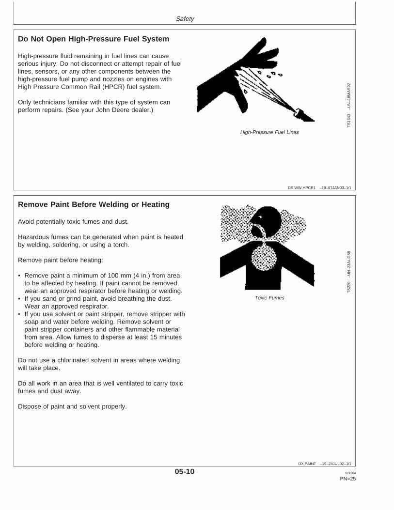
Do Not Open High-Pressure Fuel System
TS
1343
–UN
–18M
AR
92
High-Pressure Fuel Lines
High-pressure fluid remaining in fuel lines can causeserious injury. Do not disconnect or attempt repair of fuellines, sensors, or any other components between thehigh-pressure fuel pump and nozzles on engines withHigh Pressure Common Rail (HPCR) fuel system.
Only technicians familiar with this type of system canperform repairs. (See your John Deere dealer.)
DX,PAINT –19–24JUL02–1/1
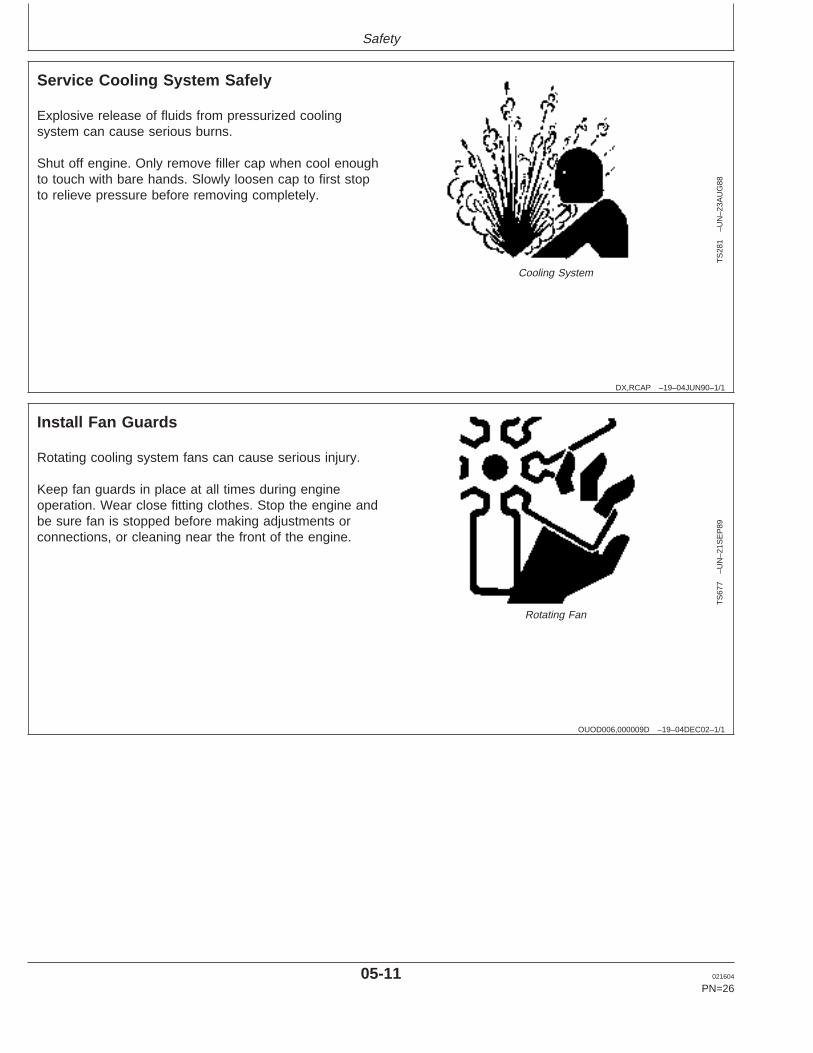
Remove Paint Before Welding or Heating
TS
220
–UN
–23A
UG
88
Toxic Fumes
Avoid potentially toxic fumes and dust.
Hazardous fumes can be generated when paint is heatedby welding, soldering, or using a torch.
Remove paint before heating:
• Remove paint a minimum of 100 mm (4 in.) from areato be affected by heating. If paint cannot be removed,wear an approved respirator before heating or welding.
• If you sand or grind paint, avoid breathing the dust.Wear an approved respirator.
• If you use solvent or paint stripper, remove stripper withsoap and water before welding. Remove solvent orpaint stripper containers and other flammable materialfrom area. Allow fumes to disperse at least 15 minutesbefore welding or heating.
Do not use a chlorinated solvent in areas where weldingwill take place.
Do all work in an area that is well ventilated to carry toxicfumes and dust away.
Dispose of paint and solvent properly.
05-10 021604
PN=25
https://www.truck-manuals.net/
Safety
DX,RCAP –19–04JUN90–1/1
Service Cooling System Safely
TS
281
–UN
–23A
UG
88
Cooling System
Explosive release of fluids from pressurized coolingsystem can cause serious burns.
Shut off engine. Only remove filler cap when cool enoughto touch with bare hands. Slowly loosen cap to first stopto relieve pressure before removing completely.
OUOD006,000009D –19–04DEC02–1/1
Install Fan Guards
TS
677
–UN
–21S
EP
89
Rotating Fan
Rotating cooling system fans can cause serious injury.
Keep fan guards in place at all times during engineoperation. Wear close fitting clothes. Stop the engine andbe sure fan is stopped before making adjustments orconnections, or cleaning near the front of the engine.
05-11 021604
PN=26
https://www.truck-manuals.net/
Safety
OUOD006,000009E –19–04DEC02–1/1
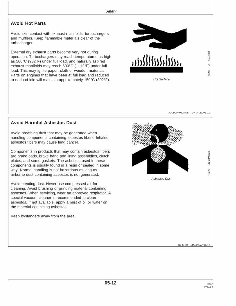
Avoid Hot Parts
TS
271
–UN
–23A
UG
88
Hot Surface
Avoid skin contact with exhaust manifolds, turbochargersand mufflers. Keep flammable materials clear of theturbocharger.
External dry exhaust parts become very hot duringoperation. Turbochargers may reach temperatures as highas 500°C (932°F) under full load, and naturally aspiredexhaust manifolds may reach 600°C (1112°F) under fullload. This may ignite paper, cloth or wooden materials.Parts on engines that have been at full load and reducedto no load idle will maintain approximately 150°C (302°F).
DX,DUST –19–15MAR91–1/1
Avoid Harmful Asbestos Dust
TS
220
–UN
–23A
UG
88
Asbestos Dust
Avoid breathing dust that may be generated whenhandling components containing asbestos fibers. Inhaledasbestos fibers may cause lung cancer.
Components in products that may contain asbestos fibersare brake pads, brake band and lining assemblies, clutchplates, and some gaskets. The asbestos used in thesecomponents is usually found in a resin or sealed in someway. Normal handling is not hazardous as long asairborne dust containing asbestos is not generated.
Avoid creating dust. Never use compressed air forcleaning. Avoid brushing or grinding material containingasbestos. When servicing, wear an approved respirator. Aspecial vacuum cleaner is recommended to cleanasbestos. If not available, apply a mist of oil or water onthe material containing asbestos.
Keep bystanders away from the area.
05-12 021604
PN=27
https://www.truck-manuals.net/
Safety
DX,SPARKS –19–03MAR93–1/1
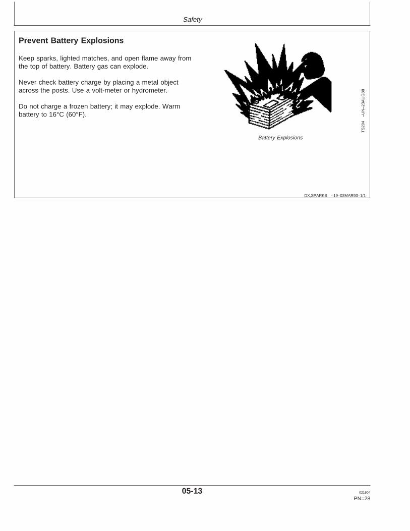
Prevent Battery Explosions
TS
204
–UN
–23A
UG
88
Battery Explosions
Keep sparks, lighted matches, and open flame away fromthe top of battery. Battery gas can explode.
Never check battery charge by placing a metal objectacross the posts. Use a volt-meter or hydrometer.
Do not charge a frozen battery; it may explode. Warmbattery to 16°C (60°F).
05-13 021604
PN=28
https://www.truck-manuals.net/
Safety
DPSG,OUO1004,2758 –19–11MAY00–1/1
Handling Batteries Safely
TS
204
–UN
–23A
UG
88
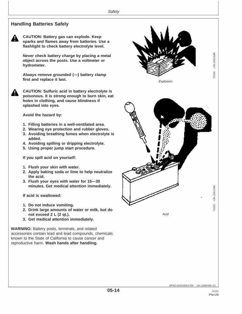
Explosion
TS
203
–UN
–23A
UG
88Acid
CAUTION: Battery gas can explode. Keepsparks and flames away from batteries. Use aflashlight to check battery electrolyte level.
Never check battery charge by placing a metalobject across the posts. Use a voltmeter orhydrometer.
Always remove grounded (—) battery clampfirst and replace it last.
CAUTION: Sulfuric acid in battery electrolyte ispoisonous. It is strong enough to burn skin, eatholes in clothing, and cause blindness ifsplashed into eyes.
Avoid the hazard by:
1. Filling batteries in a well-ventilated area.2. Wearing eye protection and rubber gloves.3. Avoiding breathing fumes when electrolyte is
added.4. Avoiding spilling or dripping electrolyte.5. Using proper jump start procedure.
If you spill acid on yourself:
1. Flush your skin with water.2. Apply baking soda or lime to help neutralize
the acid.3. Flush your eyes with water for 15—30
minutes. Get medical attention immediately.
If acid is swallowed:
1. Do not induce vomiting.2. Drink large amounts of water or milk, but do
not excee d 2 L (2 qt.).3. Get medical attention immediately.
WARNING: Battery posts, terminals, and relatedaccessories contain lead and lead compounds, chemicalsknown to the State of California to cause cancer andreproductive harm. Wash hands after handling.
05-14 021604
PN=29
https://www.truck-manuals.net/
Safety
DX,SPRAY –19–16APR92–1/1
Protect Against High Pressure Spray
TS
1343
–UN
–18M
AR
92
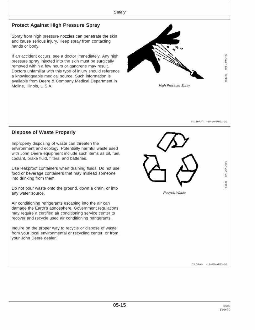
High Pressure Spray
Spray from high pressure nozzles can penetrate the skinand cause serious injury. Keep spray from contactinghands or body.
If an accident occurs, see a doctor immediately. Any highpressure spray injected into the skin must be surgicallyremoved within a few hours or gangrene may result.Doctors unfamiliar with this type of injury should referencea knowledgeable medical source. Such information isavailable from Deere & Company Medical Department inMoline, Illinois, U.S.A.
DX,DRAIN –19–03MAR93–1/1
Dispose of Waste Properly
TS
1133
–UN
–26N
OV
90
Recycle Waste
Improperly disposing of waste can threaten theenvironment and ecology. Potentially harmful waste usedwith John Deere equipment include such items as oil, fuel,coolant, brake fluid, filters, and batteries.
Use leakproof containers when draining fluids. Do not usefood or beverage containers that may mislead someoneinto drinking from them.
Do not pour waste onto the ground, down a drain, or intoany water source.
Air conditioning refrigerants escaping into the air candamage the Earth’s atmosphere. Government regulationsmay require a certified air conditioning service center torecover and recycle used air conditioning refrigerants.
Inquire on the proper way to recycle or dispose of wastefrom your local environmental or recycling center, or fromyour John Deere dealer.
05-15 021604
PN=30
https://www.truck-manuals.net/
Fuels, Lubricants, and Coolant
OURGP11,000018C –19–12FEB04–1/1
Diesel Fuel
Consult your local fuel distributor for properties of thediesel fuel available in your area.
In general, diesel fuels are blended to satisfy the lowtemperature requirements of the geographical area inwhich they are marketed.
Diesel fuels specified to EN 590 or ASTM D975 arerecommended.
In all cases, the fuel shall meet the followingproperties:
Cetane number of 45 minimum. Cetane numbergreater than 50 is preferred, especially fortemperatures below -20°C (-4°F) or elevations above1500 m (5000 ft).
Cold Filter Plugging Point (CFPP) below theexpected low temperature OR Cloud Point at least5°C (9°F) below the expected low temperature.
Fuel lubricity should pass a minimum of 3100 gramload level as measured by the BOCLE scuffing test.
Sulfur content:
• Sulfur content should not exceed 0.5%. Sulfurcontent less than 0.05% is preferred.
• If diesel fuel with sulfur content greater than 0.5%sulfur content is used, reduce the service interval forengine oil and filter by 50%.
• DO NOT use diesel fuel with sulfur content greaterthan 1.0%.
Bio-diesel fuels may be used ONLY if the fuelproperties meet DIN 51606 or equivalent specification.
DO NOT mix used engine oil or any other type oflubricant with diesel fuel.
DX,FUEL5 –19–19DEC03–1/1
Lubricity of Diesel Fuel
Diesel fuel must have adequate lubricity to ensureproper operation and durability of fuel injection systemcomponents.
ASTM D975 and EN 590 specifications do not requirefuels to pass a fuel lubricity test.
Sulfur content of diesel fuel for highway use is lessthan 0.05% (500 ppm) in the United States andCanada, and less than 0.035% (350 ppm) in theEuropean Union.
Experience shows that some low sulfur diesel fuelsmay have inadequate lubricity and their use mayreduce performance in fuel injection systems due toinadequate lubrication of injection pump components.The lower concentration of aromatic compounds in
these fuels also adversely affects injection pump sealsand may result in leaks.
Use of low lubricity diesel fuels may also causeaccelerated wear, injection nozzle erosion or corrosion,engine speed instability, hard starting, low power, andengine smoke.
Fuel lubricity should pass a minimum load level of3100 grams as measured by ASTM D6078 ormaximum scar diameter of 0.45 mm as measured byASTM D6079 or ISO 12156-1.
If fuel of low or unknown lubricity is used, add JohnDeere PREMIUM DIESEL FUEL CONDITIONER (orequivalent) at the specified concentration.
10-1 021604
PN=31
https://www.truck-manuals.net/
Fuels, Lubricants, and Coolant
DX,FUEL4 –19–19DEC03–1/1
Handling and Storing Diesel Fuel
CAUTION: Handle fuel carefully. Do not fillthe fuel tank when engine is running.
DO NOT smoke while you fill the fuel tank orservice the fuel system.
Fill the fuel tank at the end of each day’s operation toprevent water condensation and freezing during coldweather.
Keep all storage tanks as full as practicable tominimize condensation.
Ensure that all fuel tank caps and covers are installedproperly to prevent moisture from entering. Monitorwater content of the fuel regularly.
When using bio-diesel fuel, the fuel filter may requiremore frequent replacement due to premature plugging.
Check engine oil level daily prior to starting engine. Arising oil level may indicate fuel dilution of the engineoil.
IMPORTANT: The fuel tank is vented through thefiller cap. If a new filler cap isrequired, always replace it with anoriginal vented cap.
When fuel is stored for an extended period or if thereis a slow turnover of fuel, add a fuel conditioner tostabilize the fuel and prevent water condensation.Contact your fuel supplier for recommendations.
DX,FUEL6 –19–06DEC00–1/1
Dieselscan Fuel Analysis
DIESELSCAN is a John Deere fuel sampling program tohelp you monitor the quality of your fuel source. It verifiesfuel type, cleanliness, water content, suitability for coldweather operation, and if fuel is within ASTMspecifications. Check with your John Deere dealer foravailability of DIESELSCAN kits.
DIESELSCAN is a trademark of Deere & Company
10-2 021604
PN=32
https://www.truck-manuals.net/
Fuels, Lubricants, and Coolant
DX,FUEL7 –19–05JAN04–1/1
Bio-Diesel Fuel
Consult your local fuel distributor for properties of thebio-diesel fuel available in your area.
Bio-diesel fuels may be used ONLY if the bio-dieselfuel properties meet the latest edition of ASTM D6751,EN 14214, or equivalent specification.
It has been found that bio-diesel fuels may improvelubricity in concentrations up to a 5% blend (alsoknown as B5) in petroleum diesel fuel.
When using a blend of bio-diesel fuel, the engine oillevel must be checked daily when the air temperatureis –10°C (14°F) or lower. If oil becomes diluted withfuel, shorten oil change intervals accordingly.
IMPORTANT: Raw pressed vegetable oils are NOTacceptable for use as fuel in anyconcentration in John Deereengines.
These oils do not burn completely,and will cause engine failure byleaving deposits on injectors and inthe combustion chamber.
A major environmental benefit of bio-diesel fuel is itsability to biodegrade. This makes proper storage and
handling of bio-diesel fuel especially important. Areasof concern include:
• Quality of new fuel• Water content of the fuel• Problems due to aging of the fuel
Potential problems resulting from deficiencies in theabove areas when using bio-diesel fuel inconcentrations above 5% may lead to the followingsymptoms:
• Power loss and deterioration of performance• Fuel leakage• Corrosion of fuel injection equipment• Coked and/or blocked injector nozzles, resulting in
engine misfire• Filter plugging• Lacquering and/or seizure of internal components• Sludge and sediments• Reduced service life of engine components
Consult your fuel supplier for additives to improvestorage and performance of bio-diesel fuels.
10-3 021604
PN=33
https://www.truck-manuals.net/
Fuels, Lubricants, and Coolant
RG,RG34710,7529 –19–25FEB03–1/2
Minimizing the Effect of Cold Weather on Diesel Engines
John Deere diesel engines are designed to operateeffectively in cold weather.
However, for effective starting and cold weatheroperation, a little extra care is necessary. Theinformation below outlines steps that can minimize theeffect that cold weather may have on starting andoperation of your engine. See your authorizedengine distributor or servicing dealer for additionalinformation and local availability of cold weather aids.
Use Grade No. 1-D Fuel
When temperatures fall below 5°C (40°F), Grade No.1-D fuel is best suited for cold weather operation.Grade No. 1-D fuel has a lower cloud point and alower pour point.
Cloud point is the temperature at which wax will beginto form in the fuel and this wax causes fuel filters toplug. Pour point is the temperature at which fuelbegins to thicken and becomes more resistant to flowthrough fuel pumps and lines.
NOTE: On an average, Grade No. 1-D fuel has alower BTU (heat content) rating than GradeNo. 2-D fuel. When using Grade No. 1-D fuelyou may notice a drop in power and fuelefficiency, but should not experience any otherengine performance effects. Check the gradeof fuel being used before troubleshooting forlow power complaints in cold weatheroperation.
Air Intake Heaters
This option is available on suffix “275” engines andlater “270” engines. Air intake heaters are located onthe cylinder head.
IMPORTANT: Do NOT use ether when starting withair intake heaters.
Fuel Heaters
Two options are available with fuel heaters: onelocation is at the inlet port of the primary fuel filter,while the other location is at the inlet port of the finalfuel filter.
Coolant Heaters
Engine block heaters (coolant) are an available optionto aid cold weather starting.
Glow Plugs
Glow plugs are used to aid cold weather starting onengines equipped with the 4 valve cylinder head (475suffix).
IMPORTANT: Do NOT use ether when starting withglow plugs.
Seasonal Viscosity Oil and Proper CoolantConcentration
Use seasonal grade viscosity engine oil based onexpected air temperature range between oil changesand a proper concentration of low silicate antifreeze asrecommended. (See DIESEL ENGINE OIL andENGINE COOLANT REQUIREMENTS later in thissection).
10-4 021604
PN=34
Continued on next page
https://www.truck-manuals.net/
Fuels, Lubricants, and Coolant
RG,RG34710,7529 –19–25FEB03–2/2
Diesel Fuel Flow Additive
IMPORTANT: Treat fuel when outside temperaturedrops below 0 °C (32°F). For bestresults, use with untreated fuel.Follow all recommended instructionson label.
Use John Deere Premium Diesel Fuel Conditioner(Winter) or equivalent to treat fuel during the coldweather season. This winter formulation is acombination diesel fuel conditioner and anti-geladditive.
Winterfronts
Use of fabric, cardboard, or solid winterfronts is notrecommended with any John Deere engine. Their usecan result in excessive engine coolant, oil, and chargeair temperatures. This can lead to reduced engine life,loss of power and poor fuel economy. Winterfrontsmay also put abnormal stress on fan and fan drivecomponents potentially causing premature failures.
If winterfronts are used, they should never totally closeoff the grill frontal area. Approximately 25% area in thecenter of the grill should remain open at all times. Atno time should the air blockage device be applieddirectly to the radiator core.
Radiator Shutters
If equipped with a thermostatically controlled radiatorshutter system, this system should be regulated insuch a way that the shutters are completely open bythe time the coolant reaches 93°C (200°F) to preventexcessive intake manifold temperatures. Manuallycontrolled systems are not recommended.
If air-to-air aftercooling is used, the shutters must becompletely open by the time the intake manifold airtemperature reaches the maximum allowabletemperature out of the charge air cooler.
For more information, see your John Deere enginedistributor or servicing dealer.
10-5 021604
PN=35
https://www.truck-manuals.net/
Fuels, Lubricants, and Coolant
DX,ENOIL4 –19–07NOV03–1/1
Diesel Engine Break-In Oil
New engines are filled at the factory with John DeereENGINE BREAK-IN OIL. During the break-in period, addJohn Deere ENGINE BREAK-IN OIL as needed tomaintain the specified oil level.
Change the oil and filter after the first 100 hours ofoperation of a new or rebuilt engine.
After engine overhaul, fill the engine with John DeereENGINE BREAK-IN OIL.
If John Deere ENGINE BREAK-IN OIL is not available,use a diesel engine oil meeting one of the following duringthe first 100 hours of operation:
• API Service Category CE• API Service Category CD• API Service Category CC• ACEA Oil Sequence E2• ACEA Oil Sequence E1
After the break-in period, use John Deere PLUS-50 orother diesel engine oil as recommended in this manual.
IMPORTANT: Do not use PLUS-50 oil or engine oilsmeeting any of the following during thefirst 100 hours of operation of a new orrebuilt engine:
API CI-4 ACEA E5API CH-4 ACEA E4API CG-4 ACEA E3API CF-4API CF-2API CF
These oils will not allow the engine tobreak-in properly.
PLUS-50 is a trademark of Deere & Company
10-6 021604
PN=36
https://www.truck-manuals.net/
Fuels, Lubricants, and Coolant
DX,ENOIL7 –19–07NOV03–1/1
Diesel Engine Oil
TS
1675
–UN
–31O
CT
03
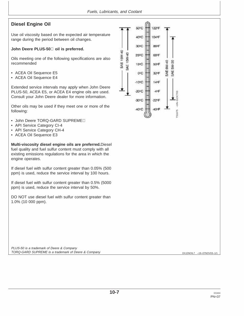
Use oil viscosity based on the expected air temperaturerange during the period between oil changes.
John Deere PLUS-50 oil is preferred.
Oils meeting one of the following specifications are alsorecommended
• ACEA Oil Sequence E5• ACEA Oil Sequence E4
Extended service intervals may apply when John DeerePLUS-50, ACEA E5, or ACEA E4 engine oils are used.Consult your John Deere dealer for more information.
Other oils may be used if they meet one or more of thefollowing:
• John Deere TORQ-GARD SUPREME• API Service Category CI-4• API Service Category CH-4• ACEA Oil Sequence E3
Multi-viscosity diesel engine oils are preferred. Dieselfuel quality and fuel sulfur content must comply with allexisting emissions regulations for the area in which theengine operates.
If diesel fuel with sulfur content greater than 0.05% (500ppm) is used, reduce the service interval by 100 hours.
If diesel fuel with sulfur content greater than 0.5% (5000ppm) is used, reduce the service interval by 50%.
DO NOT use diesel fuel with sulfur content greater than1.0% (10 000 ppm).
PLUS-50 is a trademark of Deere & CompanyTORQ-GARD SUPREME is a trademark of Deere & Company
10-7 021604
PN=37
https://www.truck-manuals.net/
Fuels, Lubricants, and Coolant
DX,ENOIL8 –19–03NOV03–1/1
Extended Diesel Engine Oil Service Intervals
When John Deere PLUS-50, ACEA E5, or ACEA E4 oilsare used with the specified John Deere filter, the serviceinterval for engine oil and filter changes may be increasedby 50% but not to exceed a maximum of 500 hours.
If John Deere PLUS-50, ACEA E5, or ACEA E4 oils areused with other than the specified John Deere filter,change the engine oil and filter at the normal serviceinterval.
If John Deere TORQ-GARD SUPREME, API CI-4, APICH-4, or ACEA E3 oils are used, change the engine oiland filter at the normal service interval.
DX,LUBMIX –19–18MAR96–1/1
Mixing of Lubricants
In general, avoid mixing different brands or types of oil.Oil manufacturers blend additives in their oils to meetcertain specifications and performance requirements.
Mixing different oils can interfere with the properfunctioning of these additives and degrade lubricantperformance.
Consult your John Deere dealer to obtain specificinformation and recommendations.
10-8 021604
PN=38
https://www.truck-manuals.net/
Fuels, Lubricants, and Coolant
DX,OILSCAN –19–02DEC02–1/1
OILSCANand COOLSCAN
T68
28A
B–U
N–1
5JU
N89
T68
29A
B–U
N–1
8OC
T88
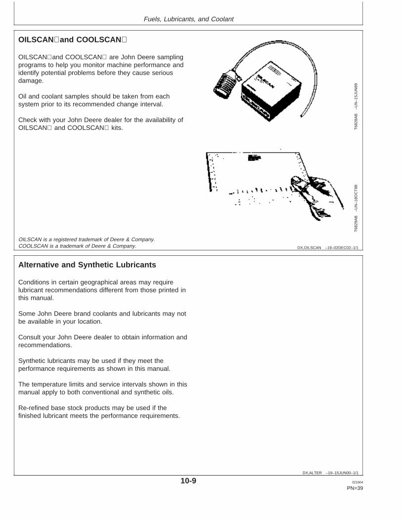
OILSCANand COOLSCAN are John Deere samplingprograms to help you monitor machine performance andidentify potential problems before they cause seriousdamage.
Oil and coolant samples should be taken from eachsystem prior to its recommended change interval.
Check with your John Deere dealer for the availability ofOILSCAN and COOLSCAN kits.
OILSCAN is a registered trademark of Deere & Company.COOLSCAN is a trademark of Deere & Company.
DX,ALTER –19–15JUN00–1/1
Alternative and Synthetic Lubricants
Conditions in certain geographical areas may requirelubricant recommendations different from those printed inthis manual.
Some John Deere brand coolants and lubricants may notbe available in your location.
Consult your John Deere dealer to obtain information andrecommendations.
Synthetic lubricants may be used if they meet theperformance requirements as shown in this manual.
The temperature limits and service intervals shown in thismanual apply to both conventional and synthetic oils.
Re-refined base stock products may be used if thefinished lubricant meets the performance requirements.
10-9 021604
PN=39
https://www.truck-manuals.net/
Fuels, Lubricants, and Coolant
DX,LUBST –19–18MAR96–1/1
Lubricant Storage
Your equipment can operate at top efficiency onlywhen clean lubricants are used.
Use clean containers to handle all lubricants.
Whenever possible, store lubricants and containers inan area protected from dust, moisture, and othercontamination. Store containers on their side to avoidwater and dirt accumulation.
Make certain that all containers are properly marked toidentify their contents.
Properly dispose of all old containers and any residuallubricant they may contain.
DX,GREA1 –19–14NOV03–1/1
Grease
TS
1667
–UN
–30J
UN
99
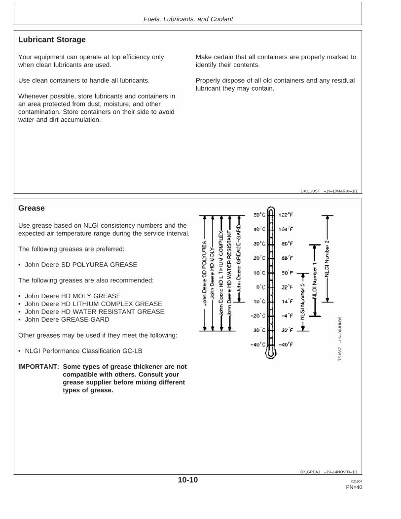
Use grease based on NLGI consistency numbers and theexpected air temperature range during the service interval.
The following greases are preferred:
• John Deere SD POLYUREA GREASE
The following greases are also recommended:
• John Deere HD MOLY GREASE• John Deere HD LITHIUM COMPLEX GREASE• John Deere HD WATER RESISTANT GREASE• John Deere GREASE-GARD
Other greases may be used if they meet the following:
• NLGI Performance Classification GC-LB
IMPORTANT: Some types of grease thickener are notcompatible with others. Consult yourgrease supplier before mixing differenttypes of grease.
10-10 021604
PN=40
https://www.truck-manuals.net/
Fuels, Lubricants, and Coolant
DX,COOL3 –19–19DEC03–1/2
Diesel Engine Coolant
The engine cooling system is filled to provideyear-round protection against corrosion and cylinderliner pitting, and winter freeze protection to -37°C(-34°F). If protection at lower temperatures is required,consult your John Deere dealer for recommendations.
John Deere COOL-GARD Prediluted Coolant ispreferred for service.
John Deere COOL-GARD Prediluted Coolant isavailable in either a concentration of 50% ethyleneglycol or a 55% propylene glycol.
Additional recommended coolants
The following engine coolant is also recommended:
• John Deere COOL-GARD Coolant Concentrate in a40% to 60% mixture of concentrate with qualitywater.
John Deere COOL-GARD coolants do not require useof supplemental coolant additives, except for periodicreplenishment of additives during the drain interval.
Other fully formulated coolants
Other fully formulated low silicate ethylene orpropylene glycol base coolants for heavy-duty enginesmay be used if they meet one of the followingspecifications:
• ASTM D6210 prediluted (50%) coolant• ASTM D6210 coolant concentrate in a 40% to 60%
mixture of concentrate with quality water
Coolants meeting ASTM D6210 do not require use ofsupplemental coolant additives, except for periodicreplenishment of additives during the drain interval.
Coolants requiring supplemental coolant additives
Other low silicate ethylene glycol base coolants forheavy-duty engines may also be used if they meet oneof the following specifications:
• ASTM D4985 ethylene glycol base prediluted (50%)coolant
• ASTM D4985 ethylene glycol base coolantconcentrate in a 40% to 60% mixture of concentratewith quality water
Coolants meeting ASTM D4985 require an initialcharge of supplemental coolant additives, formulatedfor protection of heavy duty diesel engines againstcorrosion and cylinder liner erosion and pitting. Theyalso require periodic replenishment of additives duringthe drain interval.
Other coolants
If a coolant known to meet the requirements of coolantspecifications shown in this manual is not available,use either:
• ethylene glycol or propylene glycol base prediluted(40% to 60%) coolant
• ethylene glycol or propylene glycol base coolantconcentrate in a 40% to 60% mixture of concentratewith quality water
The coolant concentrate or prediluted coolant shall beof a quality that provides cavitation protection to castiron and aluminum parts in the cooling system.
Water quality
Water quality is important to the performance of thecooling system. Distilled, deionized, or demineralizedwater is recommended for mixing with ethylene glycoland propylene glycol base engine coolant concentrate.
COOL-GARD is a trademark of Deere & Company
10-11 021604
PN=41
Continued on next page
https://www.truck-manuals.net/
Fuels, Lubricants, and Coolant
DX,COOL3 –19–19DEC03–2/2
IMPORTANT: Do not use cooling system sealingadditives or antifreeze that containssealing additives.
IMPORTANT: Do not mix ethylene glycol andpropylene glycol base coolants.
DX,COOL11 –19–19DEC03–1/1
Drain Intervals for Diesel Engine Coolant
Drain the factory fill engine coolant, flush the coolingsystem, and refill with new coolant after the first 3 yearsor 3000 hours of operation.
Subsequent drain intervals are determined by the coolantused for service. At each interval, drain the coolant, flushthe cooling system, and refill with new coolant.
When John Deere COOL-GARD is used, the draininterval may be extended to 5 years or 5000 hours ofoperation, provided that the coolant is tested annuallyAND additives are replenished, as needed, by adding asupplemental coolant additive.
If John Deere COOL-GARD is used but the coolant is nottested OR additives are not replenished by adding asupplemental coolant additive, the drain interval is 3 yearsor 3000 hours of operation
If COOL-GARD is not used, the drain interval is reducedto 2 years or 2000 hours of operation.
COOL-GARD is a trademark of Deere & Company
10-12 021604
PN=42
https://www.truck-manuals.net/
Fuels, Lubricants, and Coolant
DX,COOL4 –19–07NOV03–1/1
Supplemental Coolant Additives
The concentration of coolant additives is graduallydepleted during engine operation. For allrecommended coolants, replenish additives betweendrain intervals by adding a supplemental coolantadditive every 12 months or as determined necessaryby coolant testing.
John Deere COOLANT CONDITIONER isrecommended as a supplemental coolant additive inJohn Deere engines.
IMPORTANT: Do not add a supplemental coolantadditive when the cooling system isdrained and refilled with JohnDeereCOOL-GARD .
If other coolants are used, consult the coolant supplierand follow the manufacturer’s recommendation for useof supplemental coolant additives.
The use of non-recommended supplemental coolantadditives may result in additive drop-out and gelationof the coolant.
Add the manufacturer’s recommended concentration ofsupplemental coolant additive. DO NOT add more thanthe recommended amount.
COOL-GARD is a trademark of Deere & Company
DX,COOL9 –19–19DEC03–1/1
Testing Diesel Engine Coolant
Testing Diesel Engine Coolant
Maintaining adequate concentrations of glycol andinhibiting additives in the coolant is critical to protectthe engine and cooling system against freezing,corrosion, and cylinder liner erosion and pitting.
Test the coolant solution at intervals of 12 months orless and whenever excessive coolant is lost throughleaks or overheating.
Coolant test strips
Coolant test strips are available from your John Deeredealer. These test strips provide a simple, effective
method to check the freeze point and additive levels ofyour engine coolant.
Compare the results to the supplemental coolantadditive (SCA) chart to determine the amount ofinhibiting additives in your coolant and whether moreJohn Deere COOLANT CONDITIONER should beadded.
COOLSCAN and COOLSCAN PLUS
For a more thorough evaluation of your coolant,perform a COOLSCAN or COOLSCAN PLUS analysis,where available. See your John Deere dealer forinformation.
COOLSCAN is a trademark of Deere & CompanyCOOLSCAN PLUS is a trademark of Deere & Company
10-13 021604
PN=43
https://www.truck-manuals.net/
Fuels, Lubricants, and Coolant
DX,COOL6 –19–18MAR96–1/1
Operating in Warm Temperature Climates
John Deere engines are designed to operate using glycolbase engine coolants.
Always use a recommended glycol base engine coolant,even when operating in geographical areas where freezeprotection is not required.
IMPORTANT: Water may be used as coolant inemergency situations only.
Foaming, hot surface aluminum andiron corrosion, scaling, and cavitationwill occur when water is used as thecoolant, even when coolantconditioners are added.
Drain cooling system and refill withrecommended glycol base enginecoolant as soon as possible.
RG,RG34710,7543 –19–30JUN97–1/1
Disposing of Coolant
TS
1133
–UN
–26N
OV
90
Improperly disposing of engine coolant can threaten theenvironment and ecology.
Use leakproof containers when draining fluids. Do not usefood or beverage containers that may mislead someoneinto drinking from them.
Do not pour waste onto the ground, down a drain, or intoany water source.
Inquire on the proper way to recycle or dispose of wastefrom your local environmental or recycling center, or fromyour John Deere engine distributor or servicing dealer.
10-14 021604
PN=44
https://www.truck-manuals.net/
Instrument Panel Identification
OURGP11,0000133 –19–20NOV03–1/2
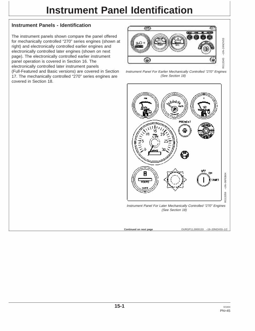
Instrument Panels - Identification
RG
1334
3–U
N–2
4NO
V03
Instrument Panel For Earlier Mechanically Controlled “270” Engines(See Section 18)
RG
1335
9–U
N–0
6FE
B04
Instrument Panel For Later Mechanically Controlled “270” Engines(See Section 18)
The instrument panels shown compare the panel offeredfor mechanically controlled “270” series engines (shown atright) and electronically controlled earlier engines andelectronically controlled later engines (shown on nextpage). The electronically controlled earlier instrumentpanel operation is covered in Section 16. Theelectronically controlled later instrument panels(Full-Featured and Basic versions) are covered in Section17. The mechanically controlled “270” series engines arecovered in Section 18.
Continued on next page
15-1 021604
PN=45
https://www.truck-manuals.net/
Instrument Panel Identification
OURGP11,0000133 –19–20NOV03–2/2
RG
1327
3–U
N–2
0NO
V03
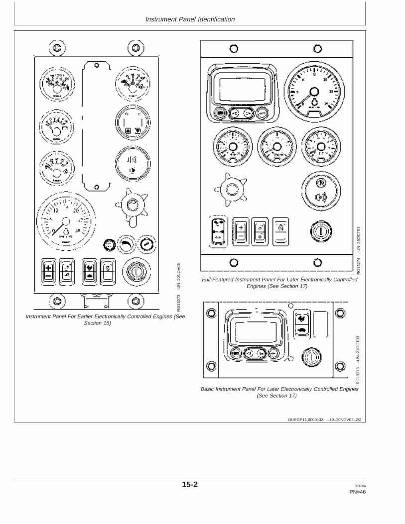
Instrument Panel For Earlier Electronically Controlled Engines (SeeSection 16)
RG
1327
4–U
N–2
8OC
T03
Full-Featured Instrument Panel For Later Electronically ControlledEngines (See Section 17)
RG
1327
5–U
N–2
1OC
T03
Basic Instrument Panel For Later Electronically Controlled Engines(See Section 17)
15-2 021604
PN=46
https://www.truck-manuals.net/
Instrument Panel - Elect. Cont. Earlier Engines
OURGP11,000027A –19–25NOV03–1/7
Instrument Panel
RG
1116
9–U
N–0
1NO
V00
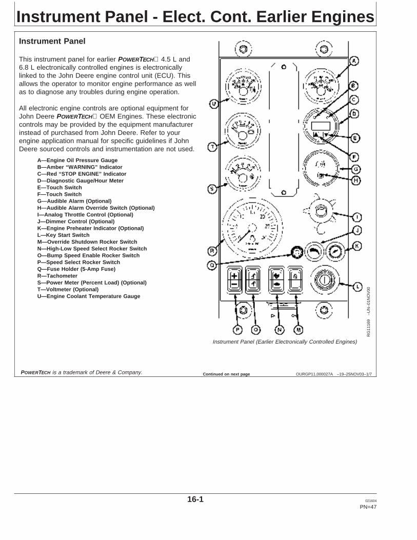
Instrument Panel (Earlier Electronically Controlled Engines)
A—Engine Oil Pressure GaugeB—Amber “WARNING” IndicatorC—Red “STOP ENGINE” IndicatorD—Diagnostic Gauge/Hour MeterE—Touch SwitchF—Touch SwitchG—Audible Alarm (Optional)H—Audible Alarm Override Switch (Optional)I—Analog Throttle Control (Optional)J—Dimmer Control (Optional)K—Engine Preheater Indicator (Optional)L—Key Start SwitchM—Override Shutdown Rocker SwitchN—High-Low Speed Select Rocker SwitchO—Bump Speed Enable Rocker SwitchP—Speed Select Rocker SwitchQ—Fuse Holder (5-Amp Fuse)R—TachometerS—Power Meter (Percent Load) (Optional)T—Voltmeter (Optional)U—Engine Coolant Temperature Gauge
This instrument panel for earlier POWERTECH 4.5 L and6.8 L electronically controlled engines is electronicallylinked to the John Deere engine control unit (ECU). Thisallows the operator to monitor engine performance as wellas to diagnose any troubles during engine operation.
All electronic engine controls are optional equipment forJohn Deere POWERTECH OEM Engines. These electroniccontrols may be provided by the equipment manufacturerinstead of purchased from John Deere. Refer to yourengine application manual for specific guidelines if JohnDeere sourced controls and instrumentation are not used.
POWERTECH is a trademark of Deere & Company. Continued on next page
16-1 021604
PN=47
https://www.truck-manuals.net/
Instrument Panel - Elect. Cont. Earlier Engines
OURGP11,000027A –19–25NOV03–2/7
RG
1116
9–U
N–0
1NO
V00
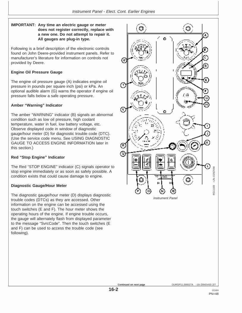
Instrument Panel
IMPORTANT: Any time an electric gauge or meterdoes not register correctly, replace witha new one. Do not attempt to repair it.All gauges are plug-in type.
Following is a brief description of the electronic controlsfound on John Deere-provided instrument panels. Refer tomanufacturer’s literature for information on controls notprovided by Deere.
Engine Oil Pressure Gauge
The engine oil pressure gauge (A) indicates engine oilpressure in pounds per square inch (psi) or kPa. Anoptional audible alarm (G) warns the operator if engine oilpressure falls below a safe operating pressure.
Amber “Warning” Indicator
The amber “WARNING” indicator (B) signals an abnormalcondition such as low oil pressure, high coolanttemperature, water in fuel, low battery voltage, etc.Observe displayed code in window of diagnosticgauge/hour meter (D) for diagnostic trouble code (DTC).(Use the service code menu. See USING DIAGNOSTICGAUGE TO ACCESS ENGINE INFORMATION later inthis section.)
Red “Stop Engine” Indicator
The Red “STOP ENGINE” indicator (C) signals operator tostop engine immediately or as soon as safely possible. Acondition exists that could cause damage to engine.
Diagnostic Gauge/Hour Meter
The diagnostic gauge/hour meter (D) displays diagnostictrouble codes (DTCs) as they are accessed. Otherinformation on the engine can be accessed using thetouch switches (E and F). The hour meter shows theoperating hours of the engine. If engine trouble occurs,the gauge will alternately flash from displayed parameterto the message “SvrcCode”. Then the touch switches (Eand F) can be used to access the trouble code (seefollowing).
16-2 021604
PN=48
Continued on next page
https://www.truck-manuals.net/
Instrument Panel - Elect. Cont. Earlier Engines
OURGP11,000027A –19–25NOV03–3/7
RG
1116
9–U
N–0
1NO
V00
Instrument Panel For Earlier Engines
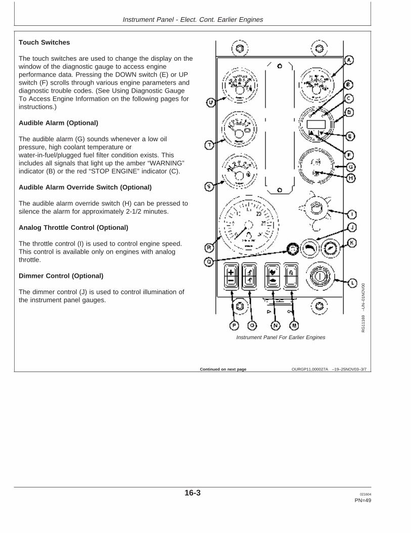
Touch Switches
The touch switches are used to change the display on thewindow of the diagnostic gauge to access engineperformance data. Pressing the DOWN switch (E) or UPswitch (F) scrolls through various engine parameters anddiagnostic trouble codes. (See Using Diagnostic GaugeTo Access Engine Information on the following pages forinstructions.)
Audible Alarm (Optional)
The audible alarm (G) sounds whenever a low oilpressure, high coolant temperature orwater-in-fuel/plugged fuel filter condition exists. Thisincludes all signals that light up the amber “WARNING”indicator (B) or the red “STOP ENGINE” indicator (C).
Audible Alarm Override Switch (Optional)
The audible alarm override switch (H) can be pressed tosilence the alarm for approximately 2-1/2 minutes.
Analog Throttle Control (Optional)
The throttle control (I) is used to control engine speed.This control is available only on engines with analogthrottle.
Dimmer Control (Optional)
The dimmer control (J) is used to control illumination ofthe instrument panel gauges.
Continued on next page
16-3 021604
PN=49
https://www.truck-manuals.net/
Instrument Panel - Elect. Cont. Earlier Engines
OURGP11,000027A –19–25NOV03–4/7
RG
1116
9–U
N–0
1NO
V00
Instrument Panel For Earlier Engines
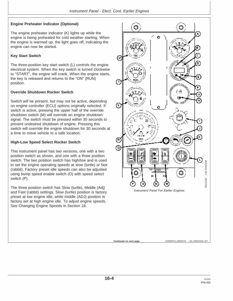
Engine Preheater Indicator (Optional)
The engine preheater indicator (K) lights up while theengine is being preheated for cold weather starting. Whenthe engine is warmed up, the light goes off, indicating theengine can now be started.
Key Start Switch
The three-position key start switch (L) controls the engineelectrical system. When the key switch is turned clockwiseto “START”, the engine will crank. When the engine starts,the key is released and returns to the “ON” (RUN)position.
Override Shutdown Rocker Switch
Switch will be present, but may not be active, dependingon engine controller (ECU) options originally selected. Ifswitch is active, pressing the upper half of the overrideshutdown switch (M) will override an engine shutdownsignal. The switch must be pressed within 30 seconds toprevent undesired shutdown of engine. Pressing thisswitch will override the engine shutdown for 30 seconds ata time to move vehicle to a safe location.
High-Low Speed Select Rocker Switch
This instrument panel has two versions, one with a twoposition switch as shown, and one with a three positionswitch. The two position switch has high/low and is usedto set the engine operating speeds at slow (turtle) or fast(rabbit). Factory preset idle speeds can also be adjustedusing bump speed enable switch (O) with speed selectswitch (P).
The three position switch has Slow (turtle), Middle (Adj)and Fast (rabbit) settings. Slow (turtle) position is factorypreset at low engine idle, while middle (ADJ) position isfactory set at high engine idle. To adjust engine speeds,See Changing Engine Speeds in Section 18.
Continued on next page
16-4 021604
PN=50
https://www.truck-manuals.net/
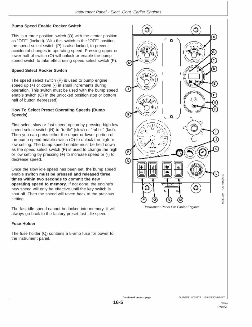
Instrument Panel - Elect. Cont. Earlier Engines
OURGP11,000027A –19–25NOV03–5/7
RG
1116
9–U
N–0
1NO
V00
Instrument Panel For Earlier Engines
Bump Speed Enable Rocker Switch
This is a three-position switch (O) with the center positionas “OFF” (locked). With this switch in the “OFF” position,the speed select switch (P) is also locked, to preventaccidental changes in operating speed. Pressing upper orlower half of switch (O) will unlock or enable the bumpspeed switch to take effect using speed select switch (P).
Speed Select Rocker Switch
The speed select switch (P) is used to bump enginespeed up (+) or down (-) in small increments duringoperation. This switch must be used with the bump speedenable switch (O) in the unlocked position (top or bottomhalf of button depressed).
How To Select Preset Operating Speeds (BumpSpeeds)
First select slow or fast speed option by pressing high-lowspeed select switch (N) to “turtle” (slow) or “rabbit” (fast).Then you can press either the upper or lower portion ofthe bump speed enable switch (O) to unlock the high orlow setting. The bump speed enable must be held downas the speed select switch (P) is used to change the highor low setting by pressing (+) to increase speed or (-) todecrease speed.
Once the slow idle speed has been set, the bump speedenable switch must be pressed and released threetimes within two seconds to commit the newoperating speed to memory. If not done, the engine’snew speed will only be effective until the key switch isshut off. Then the speed will revert back to the previoussetting.
The fast idle speed cannot be locked into memory. It willalways go back to the factory preset fast idle speed.
Fuse Holder
The fuse holder (Q) contains a 5-amp fuse for power tothe instrument panel.
16-5 021604
PN=51
Continued on next page
https://www.truck-manuals.net/
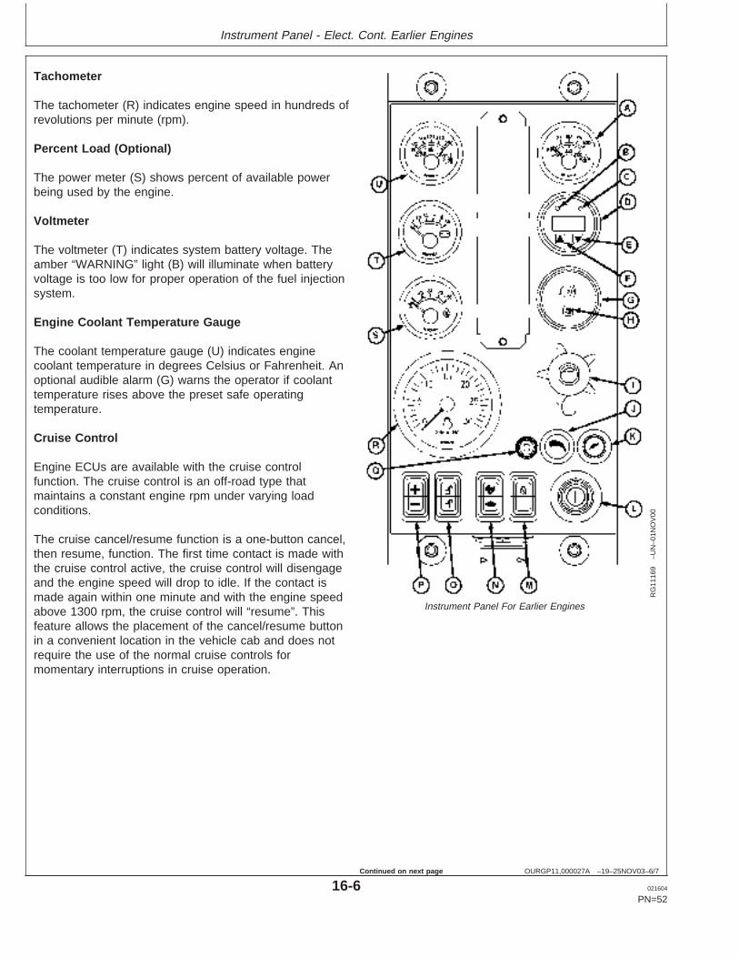
Instrument Panel - Elect. Cont. Earlier Engines
OURGP11,000027A –19–25NOV03–6/7
RG
1116
9–U
N–0
1NO
V00
Instrument Panel For Earlier Engines
Tachometer
The tachometer (R) indicates engine speed in hundreds ofrevolutions per minute (rpm).
Percent Load (Optional)
The power meter (S) shows percent of available powerbeing used by the engine.
Voltmeter
The voltmeter (T) indicates system battery voltage. Theamber “WARNING” light (B) will illuminate when batteryvoltage is too low for proper operation of the fuel injectionsystem.
Engine Coolant Temperature Gauge
The coolant temperature gauge (U) indicates enginecoolant temperature in degrees Celsius or Fahrenheit. Anoptional audible alarm (G) warns the operator if coolanttemperature rises above the preset safe operatingtemperature.
Cruise Control
Engine ECUs are available with the cruise controlfunction. The cruise control is an off-road type thatmaintains a constant engine rpm under varying loadconditions.
The cruise cancel/resume function is a one-button cancel,then resume, function. The first time contact is made withthe cruise control active, the cruise control will disengageand the engine speed will drop to idle. If the contact ismade again within one minute and with the engine speedabove 1300 rpm, the cruise control will “resume”. Thisfeature allows the placement of the cancel/resume buttonin a convenient location in the vehicle cab and does notrequire the use of the normal cruise controls formomentary interruptions in cruise operation.
16-6 021604
PN=52
Continued on next page
https://www.truck-manuals.net/
Instrument Panel - Elect. Cont. Earlier Engines
OURGP11,000027A –19–25NOV03–7/7
The cancel/resume function is intended for applicationslike agricultural tractors and sprayers that turn around atthe end of each row in a field. This allows the operator touse the throttle and/or brake to turn the vehicle around.When ready to resume field operations, the operatorbrings the engine speed above 1300 rpm and activatesthe cancel/resume function again to resume cruise speed.An internal timer gives the operator one minute tocomplete the turnaround maneuver.
The cruise control has the normal functions of:
• Cruise control power “ON” or “OFF”.• “Set” or “bump up” engine speed.• “Resume” or “bump down” engine speed.• Use vehicle brake or clutch pedal to disengage cruise
control.
The “bump up” and “bump down” speed controls allow theoperator to change the set speed. Small engine speedchanges can be made by “bumping” the control switch.Holding the “bump up” or “bump down” switch will result ingreater engine rpm changes until the engine reacheseither full speed or idle. The cruise control cannot operatebeyond the normal min/max engine speeds.
16-7 021604
PN=53
https://www.truck-manuals.net/
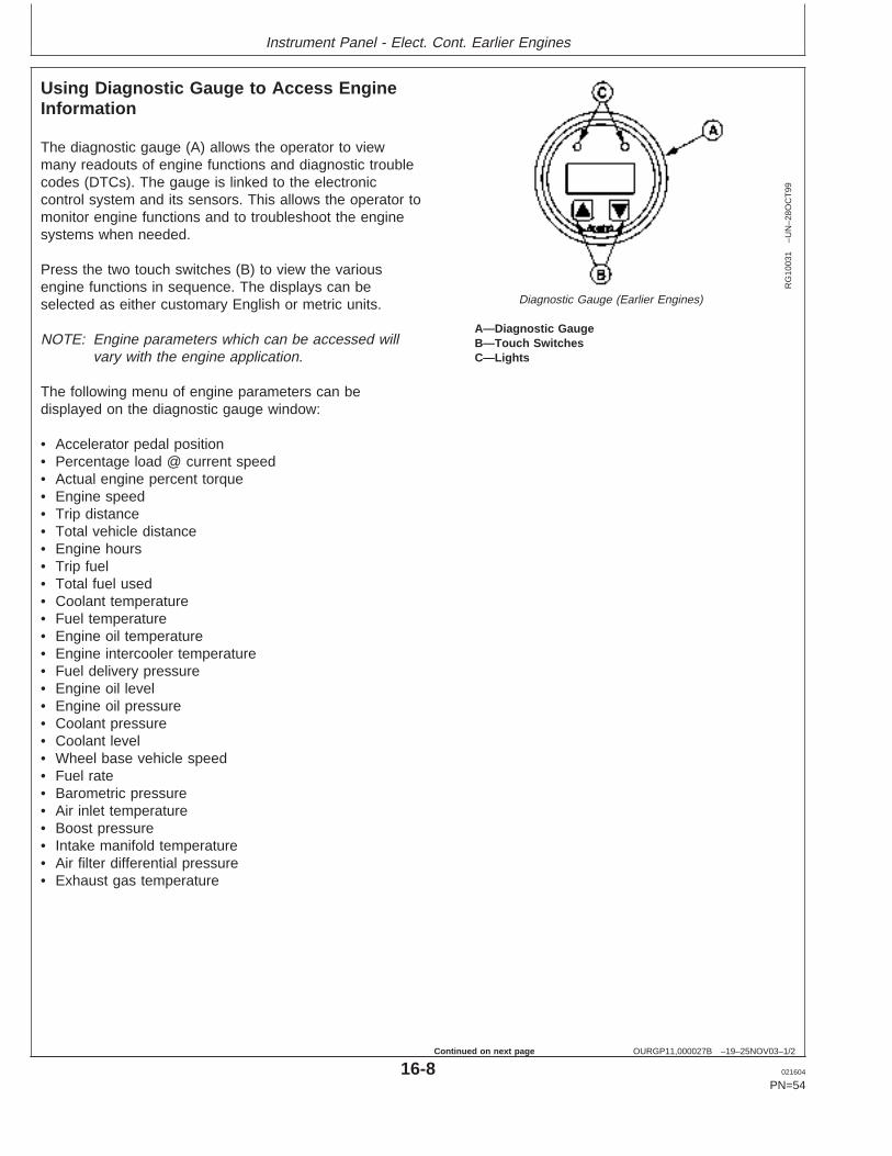
Instrument Panel - Elect. Cont. Earlier Engines
OURGP11,000027B –19–25NOV03–1/2
Using Diagnostic Gauge to Access EngineInformation
RG
1003
1–U
N–2
8OC
T99
Diagnostic Gauge (Earlier Engines)
A—Diagnostic GaugeB—Touch SwitchesC—Lights
The diagnostic gauge (A) allows the operator to viewmany readouts of engine functions and diagnostic troublecodes (DTCs). The gauge is linked to the electroniccontrol system and its sensors. This allows the operator tomonitor engine functions and to troubleshoot the enginesystems when needed.
Press the two touch switches (B) to view the variousengine functions in sequence. The displays can beselected as either customary English or metric units.
NOTE: Engine parameters which can be accessed willvary with the engine application.
The following menu of engine parameters can bedisplayed on the diagnostic gauge window:
• Accelerator pedal position• Percentage load @ current speed• Actual engine percent torque• Engine speed• Trip distance• Total vehicle distance• Engine hours• Trip fuel• Total fuel used• Coolant temperature• Fuel temperature• Engine oil temperature• Engine intercooler temperature• Fuel delivery pressure• Engine oil level• Engine oil pressure• Coolant pressure• Coolant level• Wheel base vehicle speed• Fuel rate• Barometric pressure• Air inlet temperature• Boost pressure• Intake manifold temperature• Air filter differential pressure• Exhaust gas temperature
16-8 021604
PN=54
Continued on next page
https://www.truck-manuals.net/
Instrument Panel - Elect. Cont. Earlier Engines
OURGP11,000027B –19–25NOV03–2/2
• Electrical potential (voltage)• Battery potential (voltage), switched• Transmission oil pressure• Transmission oil temperature• Injector metering rail #1 pressure• Injector metering rail #2 pressure• Estimated percent fan speed• Active service (diagnostic) codes• Stored service (diagnostic) codes
NOTE: Engine parameters which can be accessed willvary with the engine application.
The diagnostic gauge includes a two-line byeight-character backlit Liquid Crystal Display (LCD). Thetop line displays the data label, i.e. “EngHrs” and thebottom line displays the matching unit information, i.e.“1246 hrs.”. The diagnostic gauge uses two touchswitches (UP and DOWN) for scrolling through the engineparameter list and viewing the menu list. Two lights (C)(amber and red) are used to signal active troublemessages received by the diagnostic gauge.
16-9 021604
PN=55
https://www.truck-manuals.net/
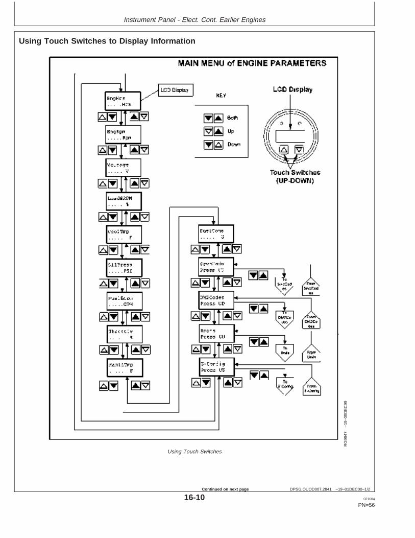
Instrument Panel - Elect. Cont. Earlier Engines
DPSG,OUOD007,2841 –19–01DEC00–1/2
Using Touch Switches to Display Information
RG
9947
–19–
09D
EC
99
Using Touch Switches
16-10 021604
PN=56
Continued on next page
https://www.truck-manuals.net/
Instrument Panel - Elect. Cont. Earlier Engines
DPSG,OUOD007,2841 –19–01DEC00–2/2
The touch switches on the diagnostic gauge allowquick and easy navigation through the menu to find theinformation needed.
The diagram on the preceding page is a typical MainMenu of Engine Parameters. The Main Menu has 14entries; the first 10 are engine data parameters, andthe last four are sub-menu entry points.
Accessing the Menus
The following two rules are used for accessing thevarious items on the menus:
1. To scroll through the parameter list, press eitherthe UP or DOWN touch switch.
2. To select or exit a sub-menu, simultaneouslypress the UP and DOWN switches.
Selecting Engine Data Parameters
To read any of the engine parameters, press either UPor DOWN switch (as shown on diagram) until the topline of the display shows the desired information.
Selecting Sub-Menus
Press either the UP or DOWN switch until the top lineof the display shows the label of the desiredsub-menu. Then press BOTH the UP and DOWNswitches at the same time. This action will select thesub-menu and the next screen on the display will listthe sub-menu items. This is also the way to accessdiagnostic trouble codes (DTCs).
16-11 021604
PN=57
https://www.truck-manuals.net/
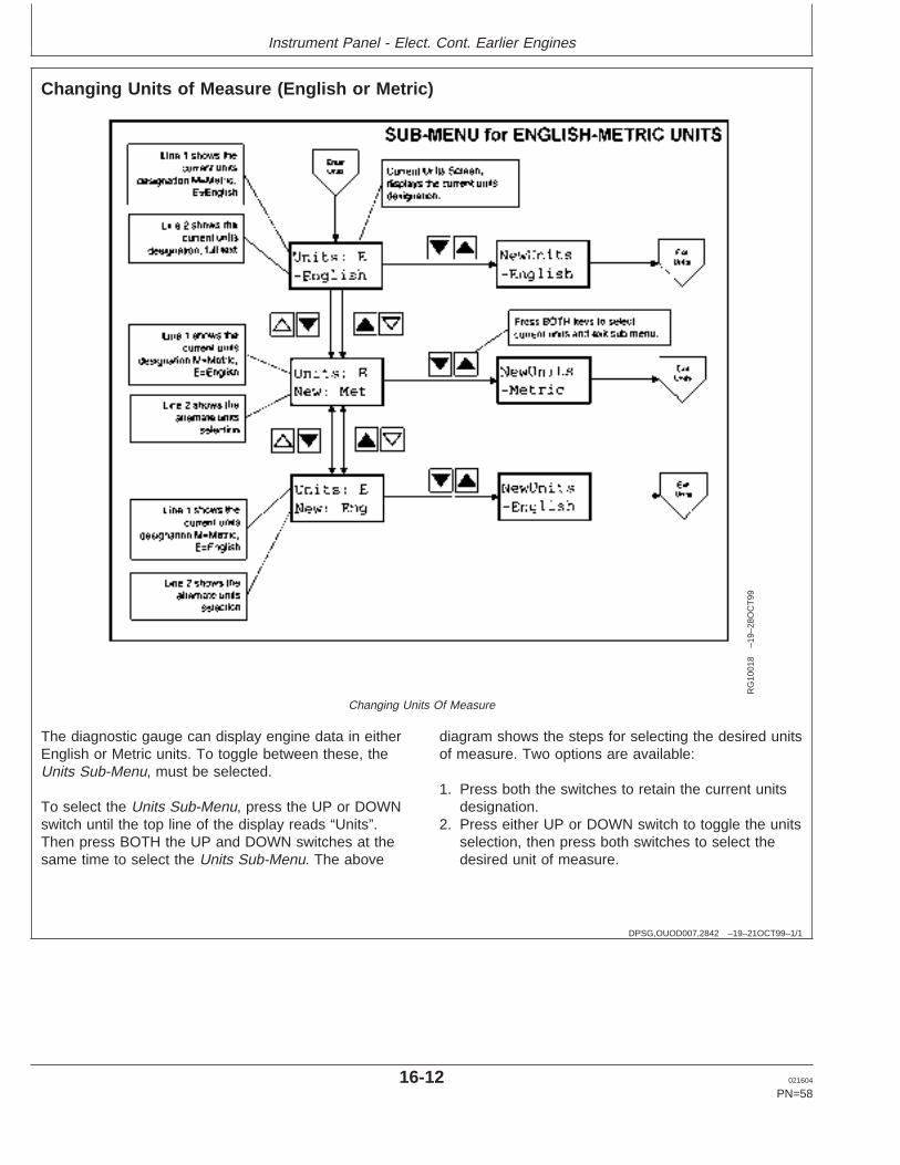
Instrument Panel - Elect. Cont. Earlier Engines
DPSG,OUOD007,2842 –19–21OCT99–1/1
Changing Units of Measure (English or Metric)
RG
1001
8–1
9–28
OC
T99
Changing Units Of Measure
The diagnostic gauge can display engine data in eitherEnglish or Metric units. To toggle between these, theUnits Sub-Menu, must be selected.
To select the Units Sub-Menu, press the UP or DOWNswitch until the top line of the display reads “Units”.Then press BOTH the UP and DOWN switches at thesame time to select the Units Sub-Menu. The above
diagram shows the steps for selecting the desired unitsof measure. Two options are available:
1. Press both the switches to retain the current unitsdesignation.
2. Press either UP or DOWN switch to toggle the unitsselection, then press both switches to select thedesired unit of measure.
16-12 021604
PN=58
https://www.truck-manuals.net/

Instrument Panel - Elect. Cont. Earlier Engines
16-13 021604
PN=59
https://www.truck-manuals.net/
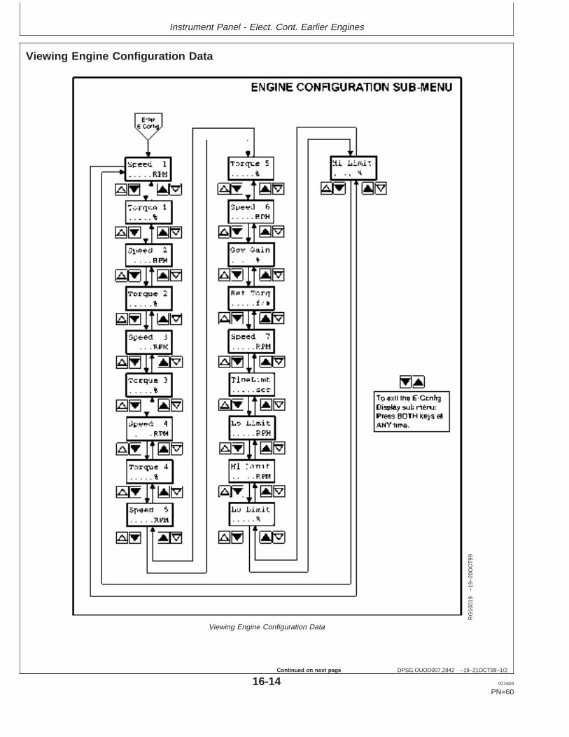
Instrument Panel - Elect. Cont. Earlier Engines
DPSG,OUOD007,2842 –19–21OCT99–1/2
Viewing Engine Configuration Data
RG
1001
9–1
9–28
OC
T99
Viewing Engine Configuration Data
16-14 021604
PN=60
Continued on next page
https://www.truck-manuals.net/
Instrument Panel - Elect. Cont. Earlier Engines
DPSG,OUOD007,2842 –19–21OCT99–2/2
The diagnostic gauge can display the engineconfiguration data stored in the engine control unit(ECU). To select the Engine Configuration Sub-Menu(see diagram on previous page), press the UP orDOWN switch until the top line of the display reads
“E-Config”. Then press BOTH the UP and DOWNswitches at the same time to select the EngineConfiguration Sub-Menu. The diagnostic gauge willdisplay the engine configuration data as shown in thediagram.
16-15 021604
PN=61
https://www.truck-manuals.net/
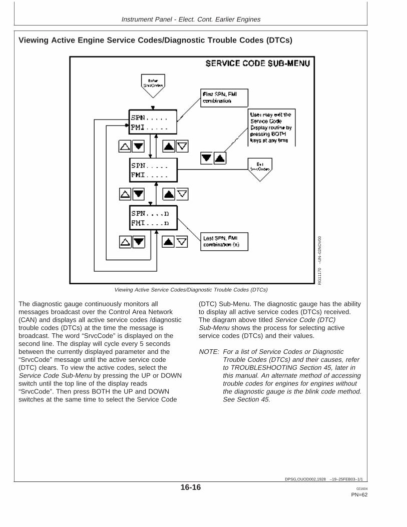
Instrument Panel - Elect. Cont. Earlier Engines
DPSG,OUOD002,1928 –19–25FEB03–1/1
Viewing Active Engine Service Codes/Diagnostic Trouble Codes (DTCs)
RG
1117
0–U
N–0
2NO
V00
Viewing Active Service Codes/Diagnostic Trouble Codes (DTCs)
The diagnostic gauge continuously monitors allmessages broadcast over the Control Area Network(CAN) and displays all active service codes /diagnostictrouble codes (DTCs) at the time the message isbroadcast. The word “SrvcCode” is displayed on thesecond line. The display will cycle every 5 secondsbetween the currently displayed parameter and the“SrvcCode” message until the active service code(DTC) clears. To view the active codes, select theService Code Sub-Menu by pressing the UP or DOWNswitch until the top line of the display reads“SrvcCode”. Then press BOTH the UP and DOWNswitches at the same time to select the Service Code
(DTC) Sub-Menu. The diagnostic gauge has the abilityto display all active service codes (DTCs) received.The diagram above titled Service Code (DTC)Sub-Menu shows the process for selecting activeservice codes (DTCs) and their values.
NOTE: For a list of Service Codes or DiagnosticTrouble Codes (DTCs) and their causes, referto TROUBLESHOOTING Section 45, later inthis manual. An alternate method of accessingtrouble codes for engines for engines withoutthe diagnostic gauge is the blink code method.See Section 45.
16-16 021604
PN=62
https://www.truck-manuals.net/
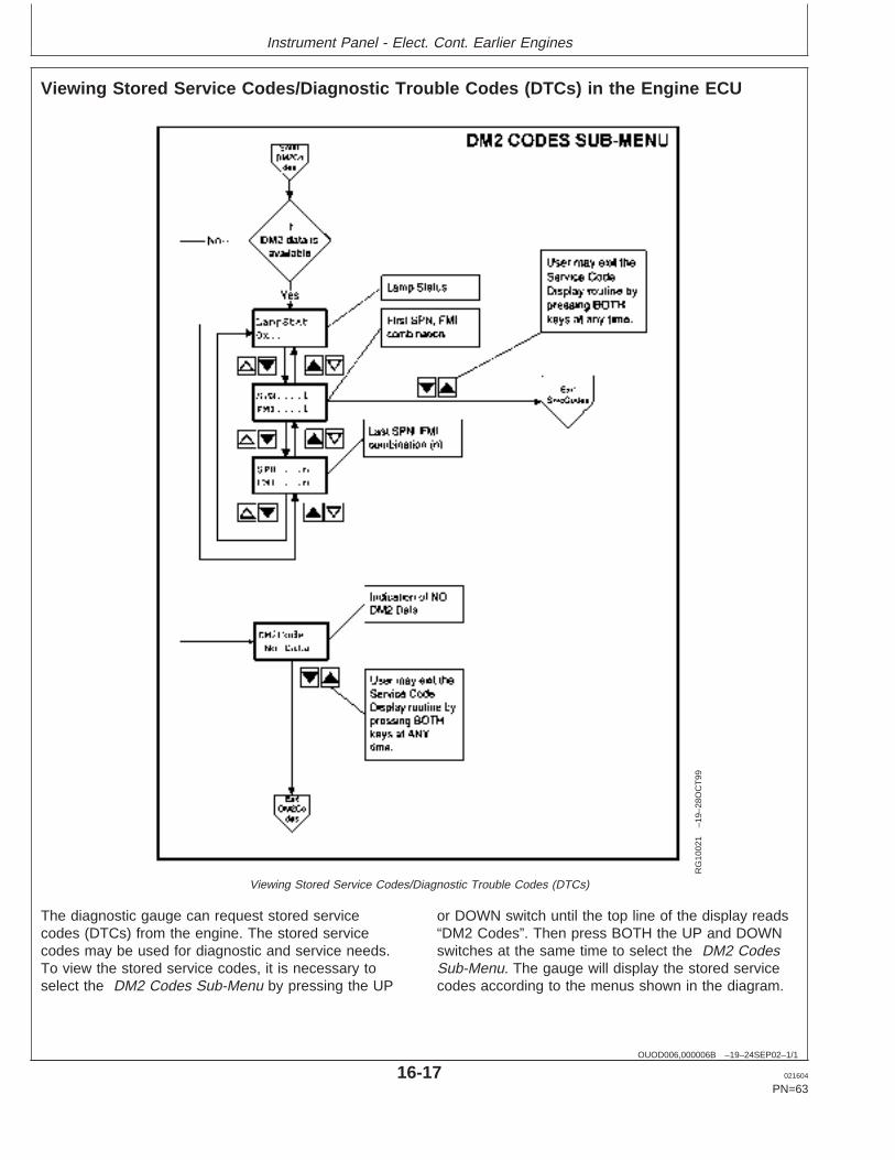
Instrument Panel - Elect. Cont. Earlier Engines
OUOD006,000006B –19–24SEP02–1/1
Viewing Stored Service Codes/Diagnostic Trouble Codes (DTCs) in the Engine ECU
RG
1002
1–1
9–28
OC
T99
Viewing Stored Service Codes/Diagnostic Trouble Codes (DTCs)
The diagnostic gauge can request stored servicecodes (DTCs) from the engine. The stored servicecodes may be used for diagnostic and service needs.To view the stored service codes, it is necessary toselect the DM2 Codes Sub-Menu by pressing the UP
or DOWN switch until the top line of the display reads“DM2 Codes”. Then press BOTH the UP and DOWNswitches at the same time to select the DM2 CodesSub-Menu. The gauge will display the stored servicecodes according to the menus shown in the diagram.
16-17 021604
PN=63
https://www.truck-manuals.net/
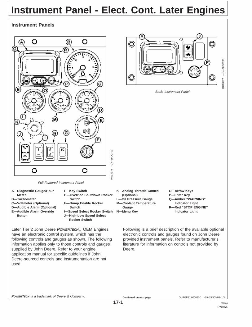
Instrument Panel - Elect. Cont. Later Engines
OURGP11,000027C –19–25NOV03–1/3
Instrument Panels
RG
1327
6–U
N–2
8OC
T03
Full-Featured Instrument Panel
RG
1327
7–U
N–2
2OC
T03
Basic Instrument Panel
A—Diagnostic Gauge/Hour F—Key Switch K—Analog Throttle Control O—Arrow KeysMeter G—Override Shutdown Rocker (Optional) P—Enter Key
B—Tachometer Switch L—Oil Pressure Gauge Q—Amber “WARNING”C—Voltmeter (Optional) H—Bump Enable Rocker M—Coolant Temperature Indicator LightD—Audible Alarm (Optional) Switch Gauge R—Red “STOP ENGINE”E—Audible Alarm Override I—Speed Select Rocker Switch N—Menu Key Indicator Light
Button J—High-Low Speed SelectRocker Switch
Later Tier 2 John Deere POWERTECH OEM Engineshave an electronic control system, which has thefollowing controls and gauges as shown. The followinginformation applies only to those controls and gaugessupplied by John Deere. Refer to your engineapplication manual for specific guidelines if JohnDeere-sourced controls and instrumentation are notused.
Following is a brief description of the available optionalelectronic controls and gauges found on John Deereprovided instrument panels. Refer to manufacturer’sliterature for information on controls not provided byDeere.
POWERTECH is a trademark of Deere & Company.
17-1 021604
PN=64
Continued on next page
https://www.truck-manuals.net/
Instrument Panel - Elect. Cont. Later Engines
OURGP11,000027C –19–25NOV03–2/3
Instrument Panel (Continued)
A—Diagnostic Gauge/Hour Meter
The diagnostic gauge (A) displays diagnostic troublecodes (DTCs) as they are accessed. Other informationon the engine can be accessed using the touch keys(N, O and P). The hour meter feature shows theoperating hours of the engine and should be used as aguide for scheduling periodic maintenance. If thediagnostic gauge receives a trouble code from anengine control unit, the current display will switch to awarning or shutdown (depending on the severity of thecode) screen that will display the trouble code number,the description of the code and the corrective actionneeded.
B—Tachometer
The tachometer (B) indicates engine speed inhundreds of revolutions per minute (rpm).
C—Voltmeter (Optional)
The voltmeter (C) indicates system battery voltage.The amber “Warning” light (P) will illuminate whenbattery voltage is too low for proper operation of thefuel injection system.
D—Audible Alarm (Optional)
The audible alarm (D) will sound whenever low oilpressure, high coolant temperature, or water-in-fuelconditions exist. This includes all signals that light upthe amber “warning” indicator (intermittent alarm) orthe red “stop engine” indicator (steady alarm).
E—Audible Alarm Override Button
The optional audible alarm has an override button (E)that silences the audible alarm for approximately twominutes when pressed.
F—Key Start Switch
The three-position key start switch (F) controls theengine electrical system. When the key switch isturned clockwise to “START”, the engine will crank.
When the engine starts, the key is released andreturns to the “ON” (RUN) position.
G—Override Shutdown Rocker Switch
Switch will be present, but may not be active,depending on engine controller (ECU) optionsoriginally selected. If switch is active, pressing theupper half of the override shutdown switch (G) willoverride an engine shutdown signal. The switch mustbe pressed within 30 seconds to prevent undesiredshutdown of engine. Pressing this switch will overridethe engine shutdown for 30 seconds at a time to movevehicle to a safe location.
H—Bump Speed Enable Rocker Switch
This is a three-position switch (H) with the centerposition as “OFF” (locked). With this switch in the“OFF” position, the speed select switch (I) is alsolocked, to prevent accidental changes in operatingspeed. Pressing upper or lower half of switch (H) willunlock or enable the bump speed switch to take effectusing speed select switch (I).
I—Speed Select Rocker Switch
The speed select switch (I) is used to bump enginespeed up (+) or down (-) in small increments duringoperation. This switch must be used with the bumpspeed enable switch (H) in the unlocked position (topor bottom half of button depressed).
J—High-Low Speed Select Rocker Switch
The high-low speed select switch (J) is used to set theengine operating speeds at slow (turtle) or fast (rabbit).Factory preset idle speeds can also be adjusted usingbump speed enable switch (H) with speed selectswitch (I).
The basic instrument panel will have the high-lowspeed select switch only. Press and hold up (+) ordown (-) to adjust engine speed as desired. Theengine speed selected will not be held in the memory.To adjust engine speeds, See Changing EngineSpeeds in Section 18.
17-2 021604
PN=65
Continued on next page
https://www.truck-manuals.net/
Instrument Panel - Elect. Cont. Later Engines
OURGP11,000027C –19–25NOV03–3/3
How To Select Preset Operating Speeds (BumpSpeeds)
First select Turtle (Slow) or Adj by pressing speedselect switch (J) to “Turtle” (slow) or “Adj”(center).Then you can press either the upper or lower portionof the bump speed enable switch (H) to unlock thesetting. The bump speed enable must be held down asthe speed select switch (J) is used to change thesetting by pressing (+) to increase speed or (-) todecrease speed.
Once the slow idle speed has been set, the bumpspeed enable switch must be pressed and releasedthree times within two seconds to commit the newoperating speed to memory. If not done, the engine’snew speed will only be effective until the key switch isshut off. Then the speed will revert back to theprevious setting.
The fast idle speed is not adjustable. It will always goback to the factory preset fast idle speed.
K—Analog Throttle Control (Optional)
The throttle control (K) is used to control enginespeed. This control is available only on engines withanalog throttle.
L—Engine Oil Pressure Gauge
The oil pressure gauge (L) indicates engine oilpressure. An audible alarm (E) warns the operator ifengine oil pressure falls below a safe operatingpressure.
M—Engine Coolant Temperature Gauge
The engine coolant temperature gauge (M) indicatesengine coolant temperature. An audible alarm (E)
warns the operator if coolant temperature rises abovethe preset safe operating temperature.
N—Menu Key
The menu key is pressed to either enter or exit themenu screens on the diagnostic gauge.
O—Arrow Keys
Use the arrow keys (O) to change the display on thewindow of the diagnostic gauge and to access engineperformance data.
Pressing the left arrow to scroll to the left or upward orthe right arrow to scroll to the right or downward. Thiswill allow you to view various engine parameters andany diagnostic trouble codes that occur.
Refer to the following story for accessing engineinformation on the diagnostic gauge using the touchkeys.
P—Enter Key
The enter key is pressed to select the parameter thatis highlighted on the screen.
Q—Amber “WARNING” Indicator Light
When light comes on, an abnormal condition exists. Itis not necessary to shutdown engine immediately, butproblem should be corrected as soon as possible.
R—Red “STOP ENGINE” Indicator Light
When light comes on, stop engine immediately or assoon as safely possible to prevent engine damage.Correct problem before restarting.
17-3 021604
PN=66
https://www.truck-manuals.net/
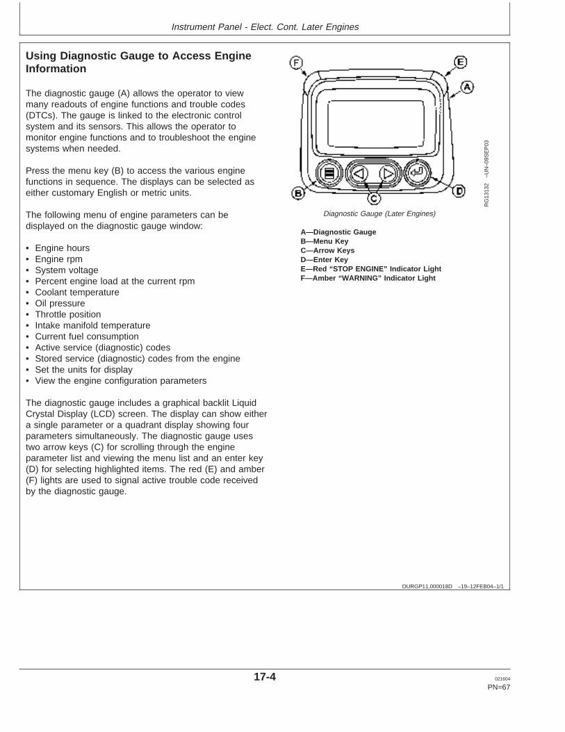
Instrument Panel - Elect. Cont. Later Engines
OURGP11,000018D –19–12FEB04–1/1
Using Diagnostic Gauge to Access EngineInformation
RG
1313
2–U
N–0
9SE
P03
Diagnostic Gauge (Later Engines)
A—Diagnostic GaugeB—Menu KeyC—Arrow KeysD—Enter KeyE—Red “STOP ENGINE” Indicator LightF—Amber “WARNING” Indicator Light
The diagnostic gauge (A) allows the operator to viewmany readouts of engine functions and trouble codes(DTCs). The gauge is linked to the electronic controlsystem and its sensors. This allows the operator tomonitor engine functions and to troubleshoot the enginesystems when needed.
Press the menu key (B) to access the various enginefunctions in sequence. The displays can be selected aseither customary English or metric units.
The following menu of engine parameters can bedisplayed on the diagnostic gauge window:
• Engine hours• Engine rpm• System voltage• Percent engine load at the current rpm• Coolant temperature• Oil pressure• Throttle position• Intake manifold temperature• Current fuel consumption• Active service (diagnostic) codes• Stored service (diagnostic) codes from the engine• Set the units for display• View the engine configuration parameters
The diagnostic gauge includes a graphical backlit LiquidCrystal Display (LCD) screen. The display can show eithera single parameter or a quadrant display showing fourparameters simultaneously. The diagnostic gauge usestwo arrow keys (C) for scrolling through the engineparameter list and viewing the menu list and an enter key(D) for selecting highlighted items. The red (E) and amber(F) lights are used to signal active trouble code receivedby the diagnostic gauge.
17-4 021604
PN=67
https://www.truck-manuals.net/
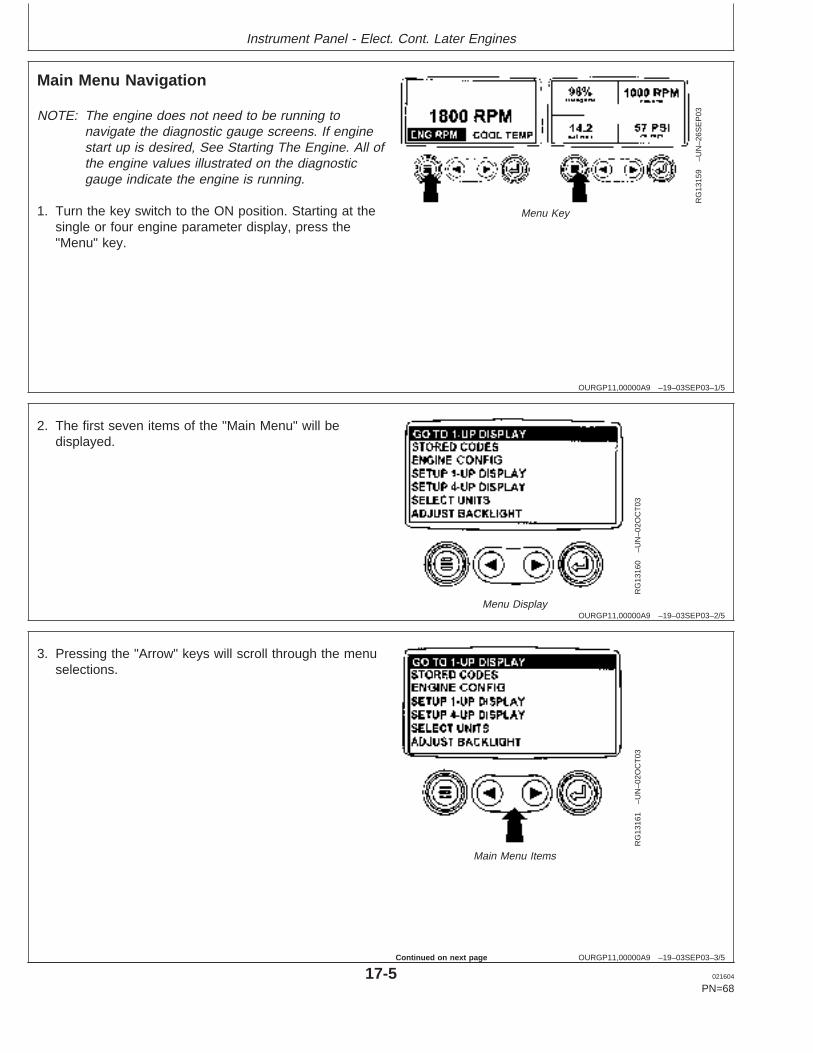
Instrument Panel - Elect. Cont. Later Engines
OURGP11,00000A9 –19–03SEP03–1/5
Main Menu Navigation
RG
1315
9–U
N–2
6SE
P03
Menu Key
NOTE: The engine does not need to be running tonavigate the diagnostic gauge screens. If enginestart up is desired, See Starting The Engine. All ofthe engine values illustrated on the diagnosticgauge indicate the engine is running.
1. Turn the key switch to the ON position. Starting at thesingle or four engine parameter display, press the"Menu" key.
OURGP11,00000A9 –19–03SEP03–2/5
RG
1316
0–U
N–0
2OC
T03
Menu Display
2. The first seven items of the "Main Menu" will bedisplayed.
OURGP11,00000A9 –19–03SEP03–3/5
RG
1316
1–U
N–0
2OC
T03
Main Menu Items
3. Pressing the "Arrow" keys will scroll through the menuselections.
17-5 021604
PN=68
Continued on next page
https://www.truck-manuals.net/

Instrument Panel - Elect. Cont. Later Engines
OURGP11,00000A9 –19–03SEP03–4/5
RG
1316
2–U
N–2
6SE
P03
Last Items On Main Menu
4. Pressing the right arrow key will scroll down to revealthe last items of "Main Menu" screen, highlighting thenext item down.
OURGP11,00000A9 –19–03SEP03–5/5
RG
1316
3–U
N–0
2OC
T03
Use Arrow Buttons To Scroll / Quadrant Display
5. Use the arrow keys to scroll to the desired menu itemor press the "Menu Button" to exit the main menu andreturn to the engine parameter display.
OURGP11,00000AB –19–03SEP03–1/6
Engine Configuration Data
RG
1315
9–U
N–2
6SE
P03
Menu Key
NOTE: The engine configuration data is a read onlyfunction.
NOTE: The engine does not need to be running tonavigate the diagnostic gauge screens. If enginestart up is desired, See Starting The Engine. All ofthe engine values illustrated on the diagnosticgauge indicate the engine is running.
1. Turn the key switch to the ON position. Starting at thesingle or four engine parameter display, press the"Menu" key.
17-6 021604
PN=69
Continued on next page
https://www.truck-manuals.net/
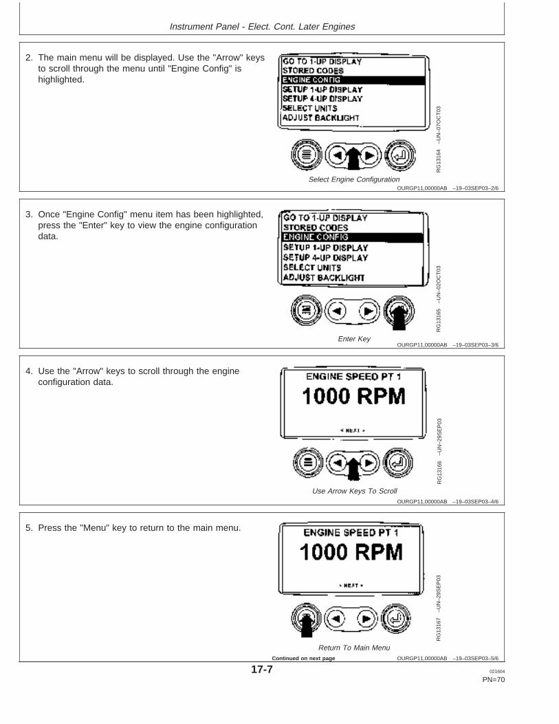
Instrument Panel - Elect. Cont. Later Engines
OURGP11,00000AB –19–03SEP03–2/6
RG
1316
4–U
N–0
7OC
T03
Select Engine Configuration
2. The main menu will be displayed. Use the "Arrow" keysto scroll through the menu until "Engine Config" ishighlighted.
OURGP11,00000AB –19–03SEP03–3/6
RG
1316
5–U
N–0
2OC
T03
Enter Key
3. Once "Engine Config" menu item has been highlighted,press the "Enter" key to view the engine configurationdata.
OURGP11,00000AB –19–03SEP03–4/6
RG
1316
6–U
N–2
9SE
P03
Use Arrow Keys To Scroll
4. Use the "Arrow" keys to scroll through the engineconfiguration data.
OURGP11,00000AB –19–03SEP03–5/6
RG
1316
7–U
N–2
9SE
P03
Return To Main Menu
5. Press the "Menu" key to return to the main menu.
17-7 021604
PN=70
Continued on next page
https://www.truck-manuals.net/
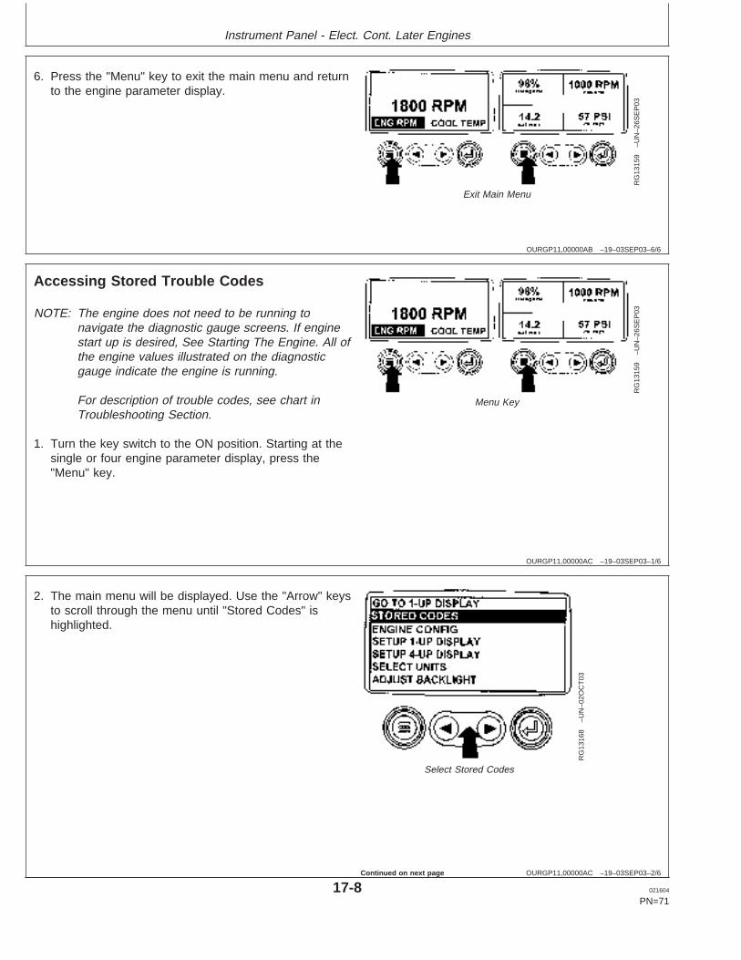
Instrument Panel - Elect. Cont. Later Engines
OURGP11,00000AB –19–03SEP03–6/6
RG
1315
9–U
N–2
6SE
P03
Exit Main Menu
6. Press the "Menu" key to exit the main menu and returnto the engine parameter display.
OURGP11,00000AC –19–03SEP03–1/6
Accessing Stored Trouble Codes
RG
1315
9–U
N–2
6SE
P03
Menu Key
NOTE: The engine does not need to be running tonavigate the diagnostic gauge screens. If enginestart up is desired, See Starting The Engine. All ofthe engine values illustrated on the diagnosticgauge indicate the engine is running.
For description of trouble codes, see chart inTroubleshooting Section.
1. Turn the key switch to the ON position. Starting at thesingle or four engine parameter display, press the"Menu" key.
OURGP11,00000AC –19–03SEP03–2/6
RG
1316
8–U
N–0
2OC
T03
Select Stored Codes
2. The main menu will be displayed. Use the "Arrow" keysto scroll through the menu until "Stored Codes" ishighlighted.
17-8 021604
PN=71
Continued on next page
https://www.truck-manuals.net/
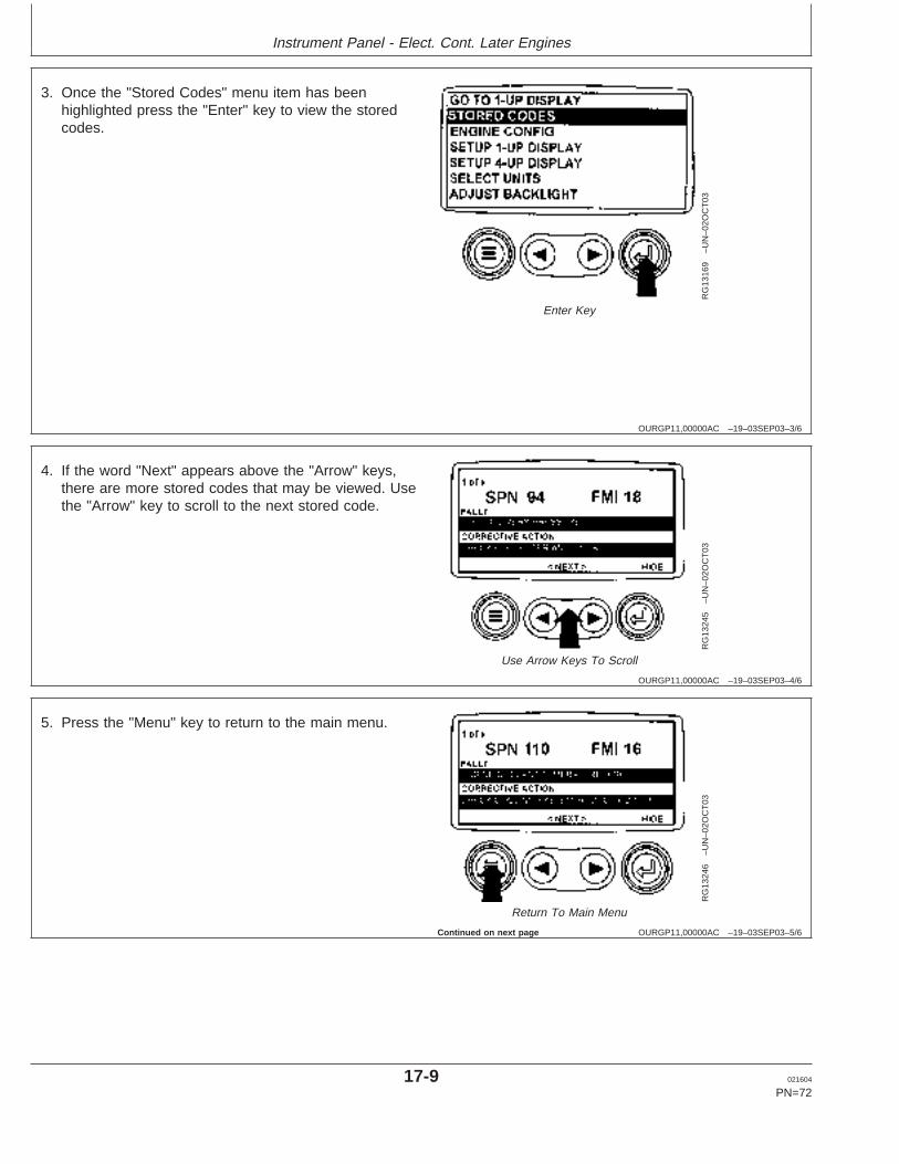
Instrument Panel - Elect. Cont. Later Engines
OURGP11,00000AC –19–03SEP03–3/6
RG
1316
9–U
N–0
2OC
T03
Enter Key
3. Once the "Stored Codes" menu item has beenhighlighted press the "Enter" key to view the storedcodes.
OURGP11,00000AC –19–03SEP03–4/6
RG
1324
5–U
N–0
2OC
T03
Use Arrow Keys To Scroll
4. If the word "Next" appears above the "Arrow" keys,there are more stored codes that may be viewed. Usethe "Arrow" key to scroll to the next stored code.
OURGP11,00000AC –19–03SEP03–5/6
RG
1324
6–U
N–0
2OC
T03
Return To Main Menu
5. Press the "Menu" key to return to the main menu.
Continued on next page
17-9 021604
PN=72
https://www.truck-manuals.net/
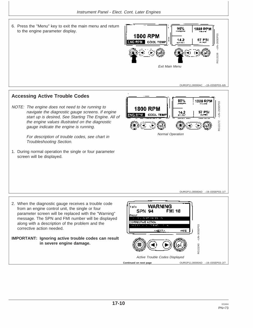
Instrument Panel - Elect. Cont. Later Engines
OURGP11,00000AC –19–03SEP03–6/6
RG
1315
9–U
N–2
6SE
P03
Exit Main Menu
6. Press the "Menu" key to exit the main menu and returnto the engine parameter display.
OURGP11,00000AD –19–03SEP03–1/7
Accessing Active Trouble Codes
RG
1317
2–U
N–2
6SE
P03
Normal Operation
NOTE: The engine does not need to be running tonavigate the diagnostic gauge screens. If enginestart up is desired, See Starting The Engine. All ofthe engine values illustrated on the diagnosticgauge indicate the engine is running.
For description of trouble codes, see chart inTroubleshooting Section.
1. During normal operation the single or four parameterscreen will be displayed.
OURGP11,00000AD –19–03SEP03–2/7
RG
1324
0–U
N–3
0SE
P03
Active Trouble Codes Displayed
2. When the diagnostic gauge receives a trouble codefrom an engine control unit, the single or fourparameter screen will be replaced with the "Warning"message. The SPN and FMI number will be displayedalong with a description of the problem and thecorrective action needed.
IMPORTANT: Ignoring active trouble codes can resultin severe engine damage.
Continued on next page
17-10 021604
PN=73
https://www.truck-manuals.net/
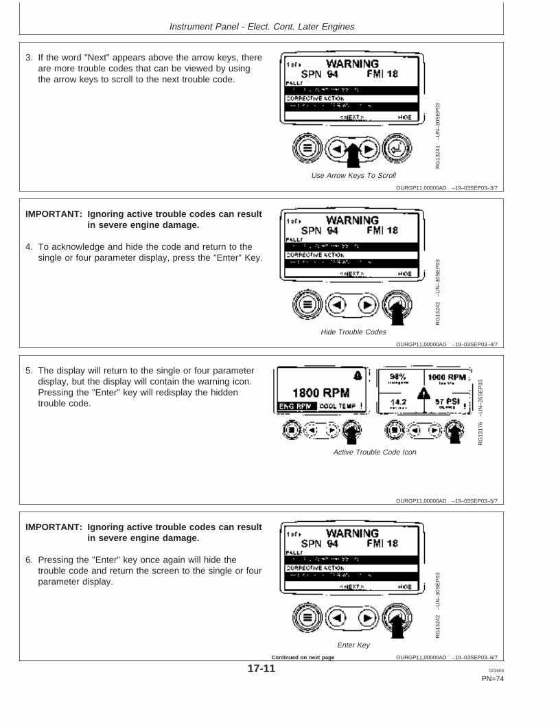
Instrument Panel - Elect. Cont. Later Engines
OURGP11,00000AD –19–03SEP03–3/7
RG
1324
1–U
N–3
0SE
P03
Use Arrow Keys To Scroll
3. If the word "Next" appears above the arrow keys, thereare more trouble codes that can be viewed by usingthe arrow keys to scroll to the next trouble code.
OURGP11,00000AD –19–03SEP03–4/7
RG
1324
2–U
N–3
0SE
P03
Hide Trouble Codes
IMPORTANT: Ignoring active trouble codes can resultin severe engine damage.
4. To acknowledge and hide the code and return to thesingle or four parameter display, press the "Enter" Key.
OURGP11,00000AD –19–03SEP03–5/7
RG
1317
6–U
N–2
6SE
P03
Active Trouble Code Icon
5. The display will return to the single or four parameterdisplay, but the display will contain the warning icon.Pressing the "Enter" key will redisplay the hiddentrouble code.
OURGP11,00000AD –19–03SEP03–6/7
RG
1324
2–U
N–3
0SE
P03
Enter Key
IMPORTANT: Ignoring active trouble codes can resultin severe engine damage.
6. Pressing the "Enter" key once again will hide thetrouble code and return the screen to the single or fourparameter display.
17-11 021604
PN=74
Continued on next page
https://www.truck-manuals.net/
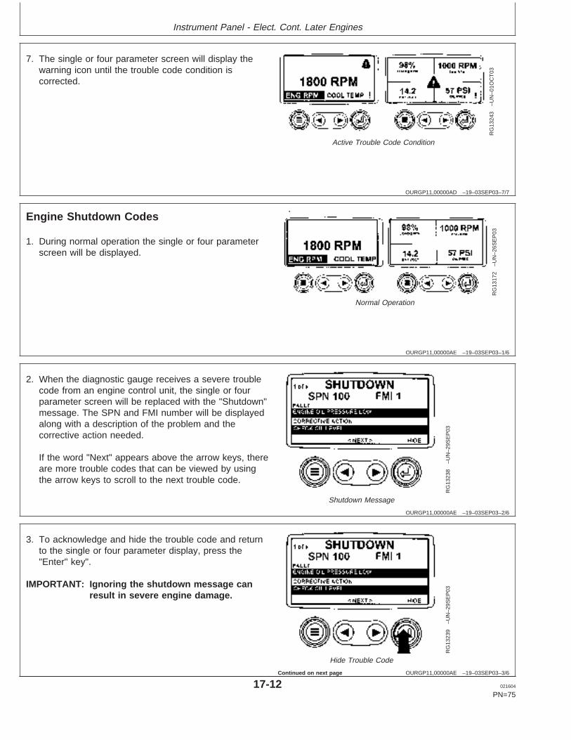
Instrument Panel - Elect. Cont. Later Engines
OURGP11,00000AD –19–03SEP03–7/7
RG
1324
3–U
N–0
1OC
T03
Active Trouble Code Condition
7. The single or four parameter screen will display thewarning icon until the trouble code condition iscorrected.
OURGP11,00000AE –19–03SEP03–1/6
Engine Shutdown Codes
RG
1317
2–U
N–2
6SE
P03
Normal Operation
1. During normal operation the single or four parameterscreen will be displayed.
OURGP11,00000AE –19–03SEP03–2/6
RG
1323
8–U
N–2
9SE
P03
Shutdown Message
2. When the diagnostic gauge receives a severe troublecode from an engine control unit, the single or fourparameter screen will be replaced with the "Shutdown"message. The SPN and FMI number will be displayedalong with a description of the problem and thecorrective action needed.
If the word "Next" appears above the arrow keys, thereare more trouble codes that can be viewed by usingthe arrow keys to scroll to the next trouble code.
OURGP11,00000AE –19–03SEP03–3/6
RG
1323
9–U
N–2
9SE
P03
Hide Trouble Code
3. To acknowledge and hide the trouble code and returnto the single or four parameter display, press the"Enter" key".
IMPORTANT: Ignoring the shutdown message canresult in severe engine damage.
17-12 021604
PN=75
Continued on next page
https://www.truck-manuals.net/
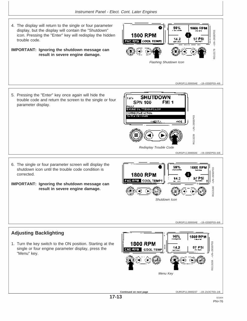
Instrument Panel - Elect. Cont. Later Engines
OURGP11,00000AE –19–03SEP03–4/6
RG
1317
9–U
N–2
6SE
P03
Flashing Shutdown Icon
4. The display will return to the single or four parameterdisplay, but the display will contain the "Shutdown"icon. Pressing the "Enter" key will redisplay the hiddentrouble code.
IMPORTANT: Ignoring the shutdown message canresult in severe engine damage.
OURGP11,00000AE –19–03SEP03–5/6
RG
1323
9–U
N–2
9SE
P03
Redisplay Trouble Code
5. Pressing the "Enter" key once again will hide thetrouble code and return the screen to the single or fourparameter display.
OURGP11,00000AE –19–03SEP03–6/6
RG
1318
0–U
N–2
6SE
P03
Shutdown Icon
6. The single or four parameter screen will display theshutdown icon until the trouble code condition iscorrected.
IMPORTANT: Ignoring the shutdown message canresult in severe engine damage.
OURGP11,0000237 –19–21OCT03–1/6
Adjusting Backlighting
RG
1315
9–U
N–2
6SE
P03
Menu Key
1. Turn the key switch to the ON position. Starting at thesingle or four engine parameter display, press the"Menu" key.
17-13 021604
PN=76
Continued on next page
https://www.truck-manuals.net/
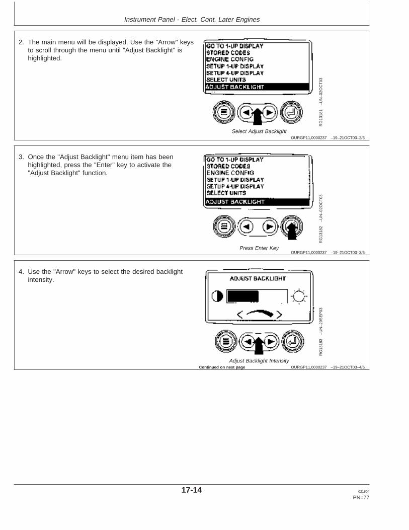
Instrument Panel - Elect. Cont. Later Engines
OURGP11,0000237 –19–21OCT03–2/6
RG
1318
1–U
N–0
2OC
T03
Select Adjust Backlight
2. The main menu will be displayed. Use the "Arrow" keysto scroll through the menu until "Adjust Backlight" ishighlighted.
OURGP11,0000237 –19–21OCT03–3/6
RG
1318
2–U
N–0
2OC
T03
Press Enter Key
3. Once the "Adjust Backlight" menu item has beenhighlighted, press the "Enter" key to activate the"Adjust Backlight" function.
OURGP11,0000237 –19–21OCT03–4/6
RG
1318
3–U
N–2
9SE
P03
Adjust Backlight Intensity
4. Use the "Arrow" keys to select the desired backlightintensity.
Continued on next page
17-14 021604
PN=77
https://www.truck-manuals.net/
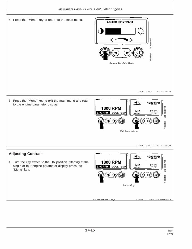
Instrument Panel - Elect. Cont. Later Engines
OURGP11,0000237 –19–21OCT03–5/6
RG
1318
4–U
N–2
6SE
P03
Return To Main Menu
5. Press the "Menu" key to return to the main menu.
OURGP11,0000237 –19–21OCT03–6/6
RG
1315
9–U
N–2
6SE
P03
Exit Main Menu
6. Press the "Menu" key to exit the main menu and returnto the engine parameter display.
OURGP11,00000AF –19–03SEP03–1/6
Adjusting Contrast
RG
1315
9–U
N–2
6SE
P03
Menu Key
1. Turn the key switch to the ON position. Starting at thesingle or four engine parameter display press the"Menu" key.
Continued on next page
17-15 021604
PN=78
https://www.truck-manuals.net/
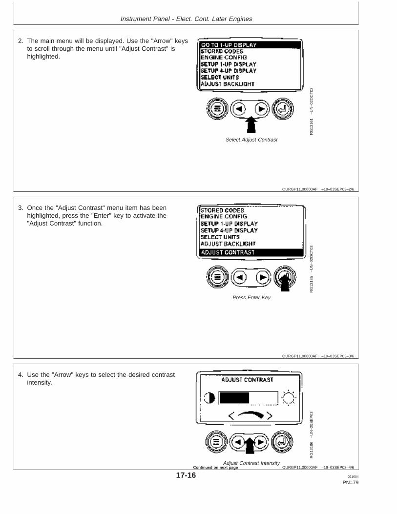
Instrument Panel - Elect. Cont. Later Engines
OURGP11,00000AF –19–03SEP03–2/6
RG
1316
1–U
N–0
2OC
T03
Select Adjust Contrast
2. The main menu will be displayed. Use the "Arrow" keysto scroll through the menu until "Adjust Contrast" ishighlighted.
OURGP11,00000AF –19–03SEP03–3/6
RG
1318
5–U
N–0
2OC
T03
Press Enter Key
3. Once the "Adjust Contrast" menu item has beenhighlighted, press the "Enter" key to activate the"Adjust Contrast" function.
OURGP11,00000AF –19–03SEP03–4/6
RG
1318
6–U
N–2
9SE
P03
Adjust Contrast Intensity
4. Use the "Arrow" keys to select the desired contrastintensity.
17-16 021604
PN=79
Continued on next page
https://www.truck-manuals.net/
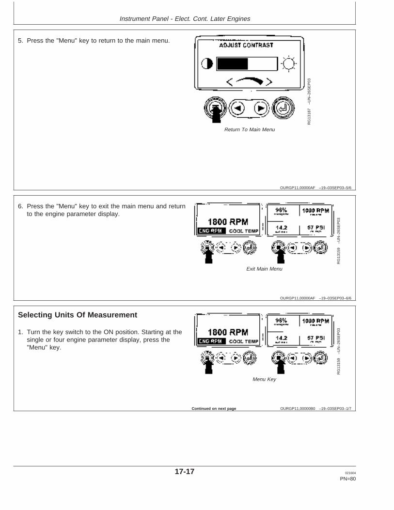
Instrument Panel - Elect. Cont. Later Engines
OURGP11,00000AF –19–03SEP03–5/6
RG
1318
7–U
N–2
6SE
P03
Return To Main Menu
5. Press the "Menu" key to return to the main menu.
OURGP11,00000AF –19–03SEP03–6/6
RG
1315
9–U
N–2
6SE
P03
Exit Main Menu
6. Press the "Menu" key to exit the main menu and returnto the engine parameter display.
OURGP11,00000B0 –19–03SEP03–1/7
Selecting Units Of Measurement
RG
1315
9–U
N–2
6SE
P03
Menu Key
1. Turn the key switch to the ON position. Starting at thesingle or four engine parameter display, press the"Menu" key.
Continued on next page
17-17 021604
PN=80
https://www.truck-manuals.net/
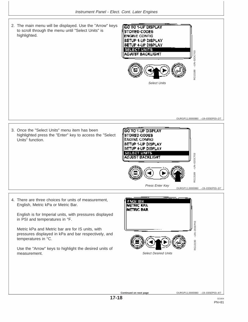
Instrument Panel - Elect. Cont. Later Engines
OURGP11,00000B0 –19–03SEP03–2/7
RG
1318
8–U
N–0
2OC
T03
Select Units
2. The main menu will be displayed. Use the "Arrow" keysto scroll through the menu until "Select Units" ishighlighted.
OURGP11,00000B0 –19–03SEP03–3/7
RG
1318
9–U
N–0
2OC
T03
Press Enter Key
3. Once the "Select Units" menu item has beenhighlighted press the "Enter" key to access the "SelectUnits" function.
OURGP11,00000B0 –19–03SEP03–4/7
RG
1319
0–U
N–2
6SE
P03
Select Desired Units
4. There are three choices for units of measurement,English, Metric kPa or Metric Bar.
English is for Imperial units, with pressures displayedin PSI and temperatures in °F.
Metric kPa and Metric bar are for IS units, withpressures displayed in kPa and bar respectively, andtemperatures in °C.
Use the "Arrow" keys to highlight the desired units ofmeasurement.
17-18 021604
PN=81
Continued on next page
https://www.truck-manuals.net/
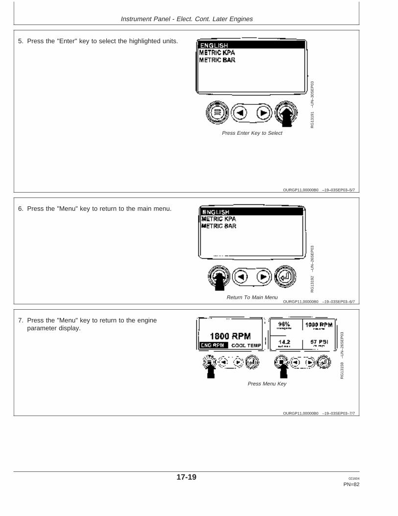
Instrument Panel - Elect. Cont. Later Engines
OURGP11,00000B0 –19–03SEP03–5/7
RG
1319
1–U
N–3
0SE
P03
Press Enter Key to Select
5. Press the "Enter" key to select the highlighted units.
OURGP11,00000B0 –19–03SEP03–6/7
RG
1319
2–U
N–2
6SE
P03
Return To Main Menu
6. Press the "Menu" key to return to the main menu.
OURGP11,00000B0 –19–03SEP03–7/7
RG
1315
9–U
N–2
6SE
P03
Press Menu Key
7. Press the "Menu" key to return to the engineparameter display.
17-19 021604
PN=82
https://www.truck-manuals.net/
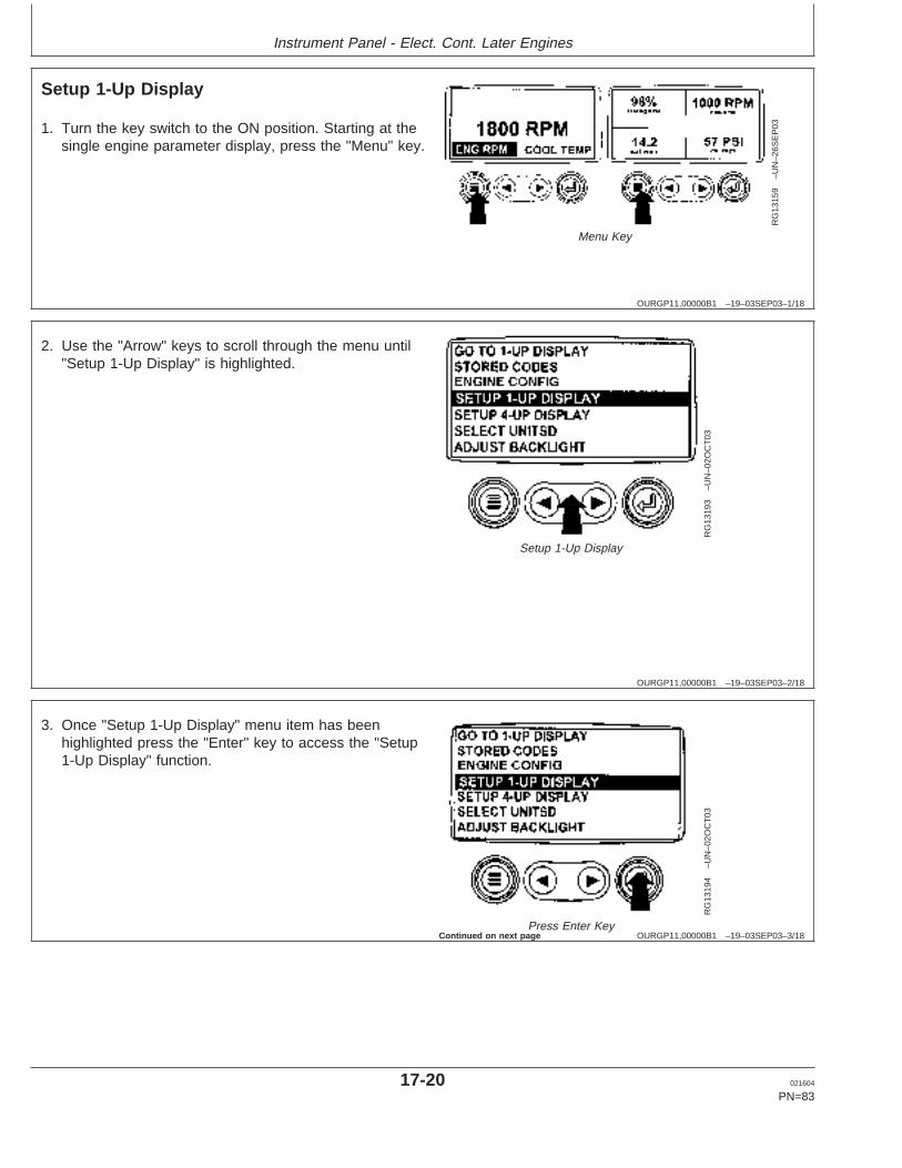
Instrument Panel - Elect. Cont. Later Engines
OURGP11,00000B1 –19–03SEP03–1/18
Setup 1-Up Display
RG
1315
9–U
N–2
6SE
P03
Menu Key
1. Turn the key switch to the ON position. Starting at thesingle engine parameter display, press the "Menu" key.
OURGP11,00000B1 –19–03SEP03–2/18
RG
1319
3–U
N–0
2OC
T03
Setup 1-Up Display
2. Use the "Arrow" keys to scroll through the menu until"Setup 1-Up Display" is highlighted.
OURGP11,00000B1 –19–03SEP03–3/18
RG
1319
4–U
N–0
2OC
T03
Press Enter Key
3. Once "Setup 1-Up Display" menu item has beenhighlighted press the "Enter" key to access the "Setup1-Up Display" function.
Continued on next page
17-20 021604
PN=83
https://www.truck-manuals.net/
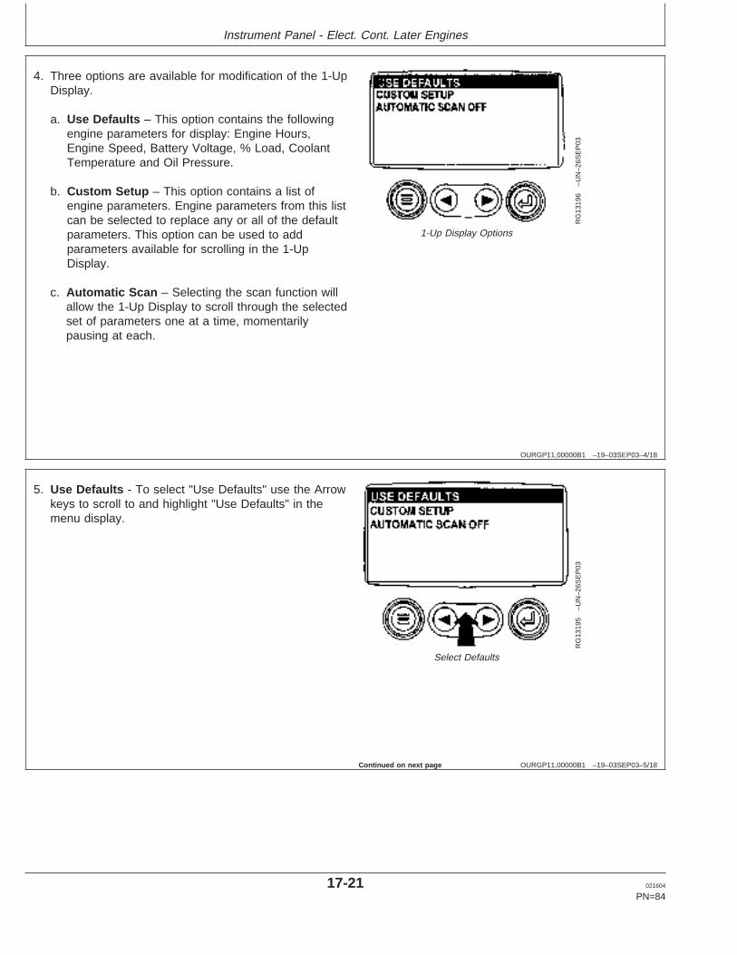
Instrument Panel - Elect. Cont. Later Engines
OURGP11,00000B1 –19–03SEP03–4/18
RG
1319
6–U
N–2
6SE
P03
1-Up Display Options
4. Three options are available for modification of the 1-UpDisplay.
a. Use Defaults – This option contains the followingengine parameters for display: Engine Hours,Engine Speed, Battery Voltage, % Load, CoolantTemperature and Oil Pressure.
b. Custom Setup – This option contains a list ofengine parameters. Engine parameters from this listcan be selected to replace any or all of the defaultparameters. This option can be used to addparameters available for scrolling in the 1-UpDisplay.
c. Automatic Scan – Selecting the scan function willallow the 1-Up Display to scroll through the selectedset of parameters one at a time, momentarilypausing at each.
OURGP11,00000B1 –19–03SEP03–5/18
RG
1319
5–U
N–2
6SE
P03
Select Defaults
5. Use Defaults - To select "Use Defaults" use the Arrowkeys to scroll to and highlight "Use Defaults" in themenu display.
Continued on next page
17-21 021604
PN=84
https://www.truck-manuals.net/
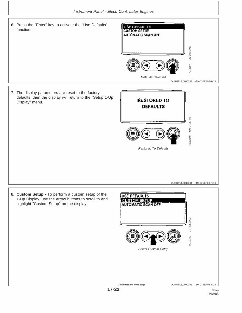
Instrument Panel - Elect. Cont. Later Engines
OURGP11,00000B1 –19–03SEP03–6/18
RG
1319
7–U
N–2
9SE
P03
Defaults Selected
6. Press the "Enter" key to activate the "Use Defaults"function.
OURGP11,00000B1 –19–03SEP03–7/18
RG
1314
9–U
N–2
4SE
P03
Restored To Defaults
7. The display parameters are reset to the factorydefaults, then the display will return to the "Setup 1-UpDisplay" menu.
OURGP11,00000B1 –19–03SEP03–8/18
RG
1319
8–U
N–2
6SE
P03
Select Custom Setup
8. Custom Setup - To perform a custom setup of the1-Up Display, use the arrow buttons to scroll to andhighlight "Custom Setup" on the display.
17-22 021604
PN=85
Continued on next page
https://www.truck-manuals.net/
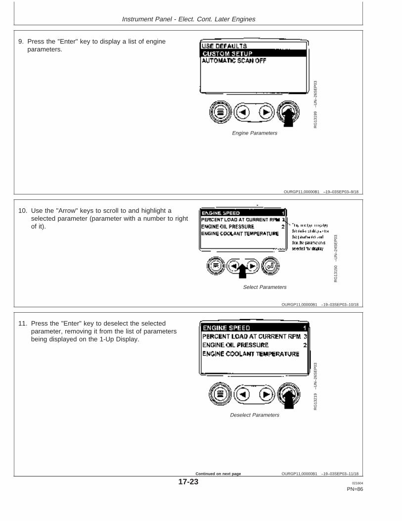
Instrument Panel - Elect. Cont. Later Engines
OURGP11,00000B1 –19–03SEP03–9/18
RG
1319
9–U
N–2
6SE
P03
Engine Parameters
9. Press the "Enter" key to display a list of engineparameters.
OURGP11,00000B1 –19–03SEP03–10/18
RG
1315
0–U
N–2
4SE
P03
Select Parameters
10. Use the "Arrow" keys to scroll to and highlight aselected parameter (parameter with a number to rightof it).
OURGP11,00000B1 –19–03SEP03–11/18
RG
1321
9–U
N–2
6SE
P03
Deselect Parameters
11. Press the "Enter" key to deselect the selectedparameter, removing it from the list of parametersbeing displayed on the 1-Up Display.
17-23 021604
PN=86
Continued on next page
https://www.truck-manuals.net/
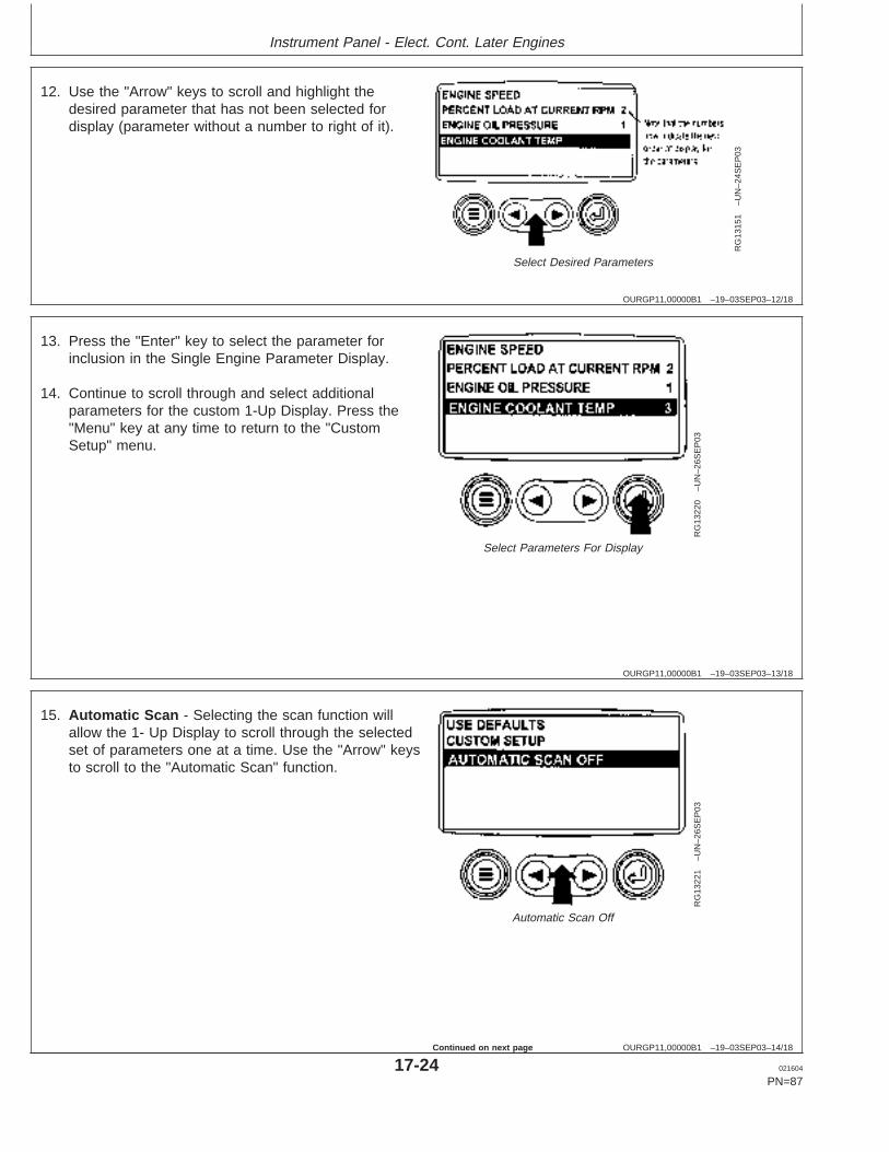
Instrument Panel - Elect. Cont. Later Engines
OURGP11,00000B1 –19–03SEP03–12/18
RG
1315
1–U
N–2
4SE
P03
Select Desired Parameters
12. Use the "Arrow" keys to scroll and highlight thedesired parameter that has not been selected fordisplay (parameter without a number to right of it).
OURGP11,00000B1 –19–03SEP03–13/18
RG
1322
0–U
N–2
6SE
P03
Select Parameters For Display
13. Press the "Enter" key to select the parameter forinclusion in the Single Engine Parameter Display.
14. Continue to scroll through and select additionalparameters for the custom 1-Up Display. Press the"Menu" key at any time to return to the "CustomSetup" menu.
OURGP11,00000B1 –19–03SEP03–14/18
RG
1322
1–U
N–2
6SE
P03
Automatic Scan Off
15. Automatic Scan - Selecting the scan function willallow the 1- Up Display to scroll through the selectedset of parameters one at a time. Use the "Arrow" keysto scroll to the "Automatic Scan" function.
17-24 021604
PN=87
Continued on next page
https://www.truck-manuals.net/
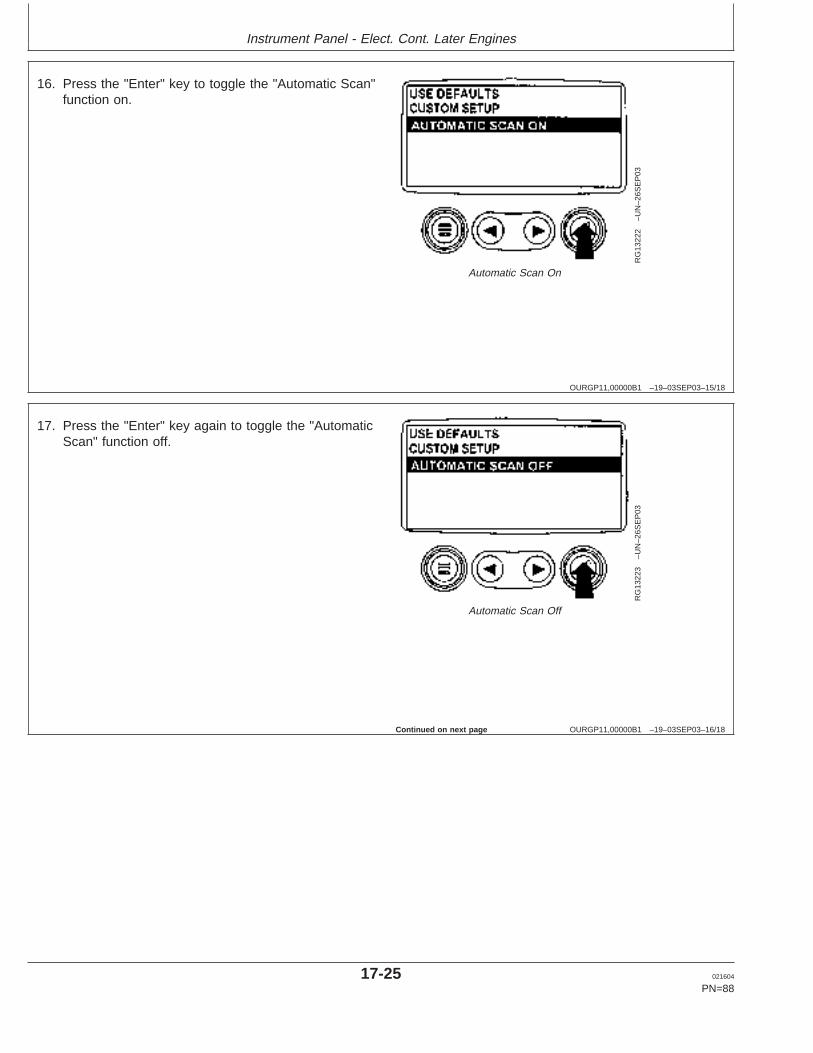
Instrument Panel - Elect. Cont. Later Engines
OURGP11,00000B1 –19–03SEP03–15/18
RG
1322
2–U
N–2
6SE
P03
Automatic Scan On
16. Press the "Enter" key to toggle the "Automatic Scan"function on.
OURGP11,00000B1 –19–03SEP03–16/18
RG
1322
3–U
N–2
6SE
P03
Automatic Scan Off
17. Press the "Enter" key again to toggle the "AutomaticScan" function off.
Continued on next page
17-25 021604
PN=88
https://www.truck-manuals.net/
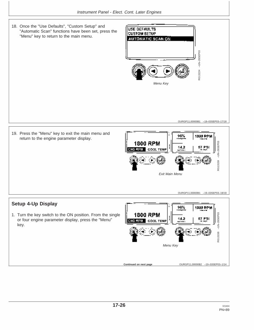
Instrument Panel - Elect. Cont. Later Engines
OURGP11,00000B1 –19–03SEP03–17/18
RG
1322
4–U
N–2
6SE
P03
Menu Key
18. Once the "Use Defaults", "Custom Setup" and"Automatic Scan" functions have been set, press the"Menu" key to return to the main menu.
OURGP11,00000B1 –19–03SEP03–18/18
RG
1315
9–U
N–2
6SE
P03
Exit Main Menu
19. Press the "Menu" key to exit the main menu andreturn to the engine parameter display.
OURGP11,00000B2 –19–03SEP03–1/14
Setup 4-Up Display
RG
1315
9–U
N–2
6SE
P03
Menu Key
1. Turn the key switch to the ON position. From the singleor four engine parameter display, press the "Menu"key.
Continued on next page
17-26 021604
PN=89
https://www.truck-manuals.net/
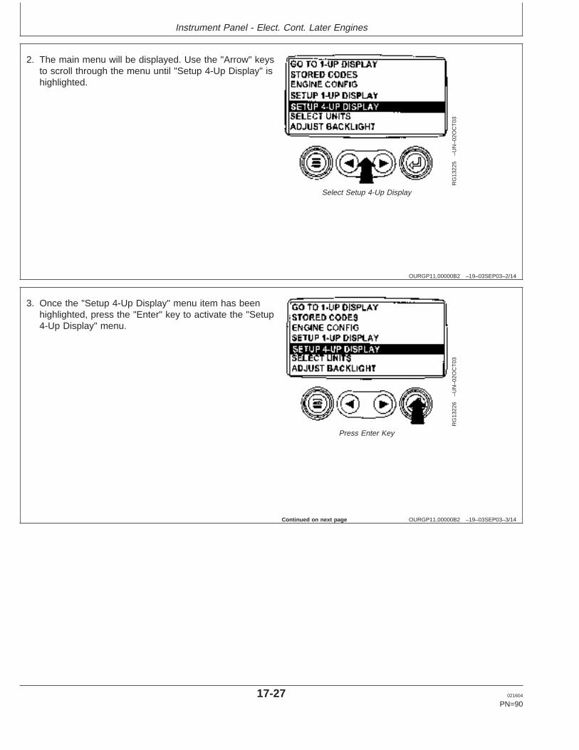
Instrument Panel - Elect. Cont. Later Engines
OURGP11,00000B2 –19–03SEP03–2/14
RG
1322
5–U
N–0
2OC
T03
Select Setup 4-Up Display
2. The main menu will be displayed. Use the "Arrow" keysto scroll through the menu until "Setup 4-Up Display" ishighlighted.
OURGP11,00000B2 –19–03SEP03–3/14
RG
1322
6–U
N–0
2OC
T03
Press Enter Key
3. Once the "Setup 4-Up Display" menu item has beenhighlighted, press the "Enter" key to activate the "Setup4-Up Display" menu.
Continued on next page
17-27 021604
PN=90
https://www.truck-manuals.net/
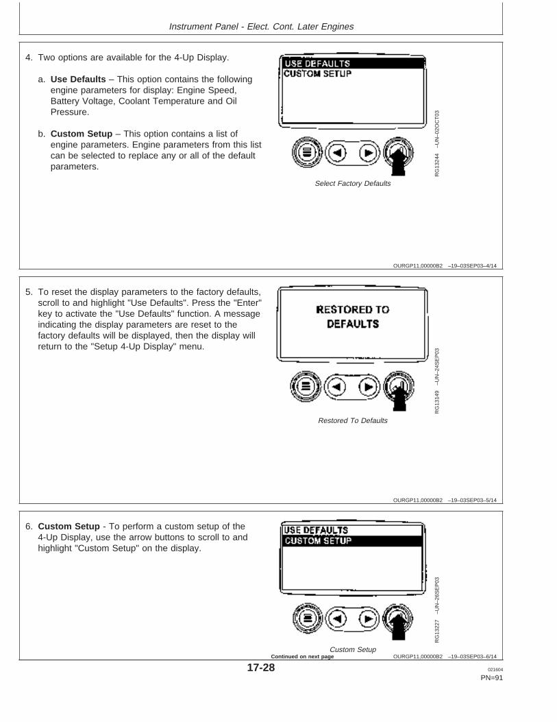
Instrument Panel - Elect. Cont. Later Engines
OURGP11,00000B2 –19–03SEP03–4/14
RG
1324
4–U
N–0
2OC
T03
Select Factory Defaults
4. Two options are available for the 4-Up Display.
a. Use Defaults – This option contains the followingengine parameters for display: Engine Speed,Battery Voltage, Coolant Temperature and OilPressure.
b. Custom Setup – This option contains a list ofengine parameters. Engine parameters from this listcan be selected to replace any or all of the defaultparameters.
OURGP11,00000B2 –19–03SEP03–5/14
RG
1314
9–U
N–2
4SE
P03
Restored To Defaults
5. To reset the display parameters to the factory defaults,scroll to and highlight "Use Defaults". Press the "Enter"key to activate the "Use Defaults" function. A messageindicating the display parameters are reset to thefactory defaults will be displayed, then the display willreturn to the "Setup 4-Up Display" menu.
OURGP11,00000B2 –19–03SEP03–6/14
RG
1322
7–U
N–2
6SE
P03
Custom Setup
6. Custom Setup - To perform a custom setup of the4-Up Display, use the arrow buttons to scroll to andhighlight "Custom Setup" on the display.
17-28 021604
PN=91
Continued on next page
https://www.truck-manuals.net/
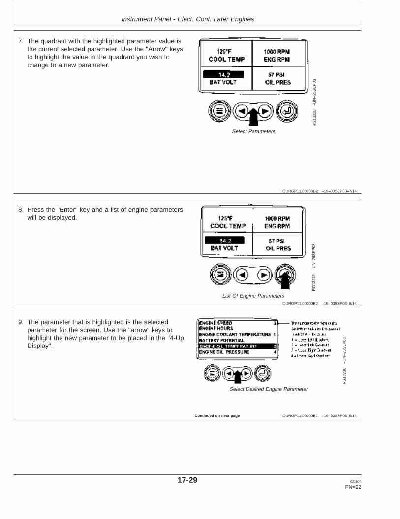
Instrument Panel - Elect. Cont. Later Engines
OURGP11,00000B2 –19–03SEP03–7/14
RG
1322
8–U
N–2
6SE
P03
Select Parameters
7. The quadrant with the highlighted parameter value isthe current selected parameter. Use the "Arrow" keysto highlight the value in the quadrant you wish tochange to a new parameter.
OURGP11,00000B2 –19–03SEP03–8/14
RG
1322
9–U
N–2
6SE
P03
List Of Engine Parameters
8. Press the "Enter" key and a list of engine parameterswill be displayed.
OURGP11,00000B2 –19–03SEP03–9/14
RG
1323
0–U
N–2
6SE
P03
Select Desired Engine Parameter
9. The parameter that is highlighted is the selectedparameter for the screen. Use the "arrow" keys tohighlight the new parameter to be placed in the "4-UpDisplay".
Continued on next page
17-29 021604
PN=92
https://www.truck-manuals.net/
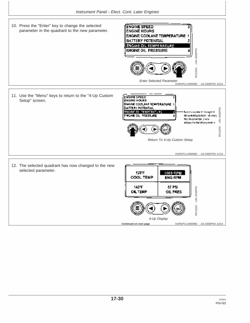
Instrument Panel - Elect. Cont. Later Engines
OURGP11,00000B2 –19–03SEP03–10/14
RG
1323
1–U
N–2
6SE
P03
Enter Selected Parameter
10. Press the "Enter" key to change the selectedparameter in the quadrant to the new parameter.
OURGP11,00000B2 –19–03SEP03–11/14
RG
1323
2–U
N–2
6SE
P03
Return To 4-Up Custom Setup
11. Use the "Menu" keys to return to the "4-Up CustomSetup" screen.
OURGP11,00000B2 –19–03SEP03–12/14
RG
1315
3–U
N–2
4SE
P03
4-Up Display
12. The selected quadrant has now changed to the newselected parameter.
Continued on next page
17-30 021604
PN=93
https://www.truck-manuals.net/
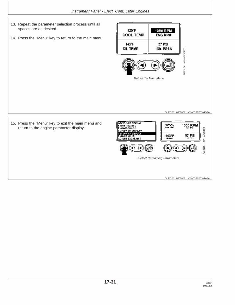
Instrument Panel - Elect. Cont. Later Engines
OURGP11,00000B2 –19–03SEP03–13/14
RG
1315
4–U
N–2
4SE
P03
Return To Main Menu
13. Repeat the parameter selection process until allspaces are as desired.
14. Press the "Menu" key to return to the main menu.
OURGP11,00000B2 –19–03SEP03–14/14
RG
1315
5–U
N–0
7OC
T03
Select Remaining Parameters
15. Press the "Menu" key to exit the main menu andreturn to the engine parameter display.
17-31 021604
PN=94
https://www.truck-manuals.net/
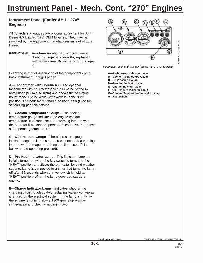
Instrument Panel - Mech. Cont. “270” Engines
OURGP11,000018E –19–12FEB04–1/2
Instrument Panel (Earlier 4.5 L “270”Engines)
RG
6574
A–U
N–0
7JA
N03
Instrument Panel and Gauges (Earlier 4.5 L “270” Engines)
A—Tachometer with HourmeterB—Coolant Temperature GaugeC—Oil Pressure GaugeD—Pre-Heat Indicator LampE—Charge Indicator LampF—Oil Pressure Indicator LampG—Coolant Temperature Indicator LampH—Key Switch
All controls and gauges are optional equipment for JohnDeere 4.5 L suffix “270” OEM Engines. They may beprovided by the equipment manufacturer instead of JohnDeere.
IMPORTANT: Any time an electric gauge or meterdoes not register correctly, replace itwith a new one. Do not attempt to repairit.
Following is a brief description of the components on abasic instrument (gauge) panel:
A—Tachometer with Hourmeter - The optionaltachometer with hourmeter indicates engine speed inrevolutions per minute (rpm) and shows the operatinghours of the engine while key switch is in the “ON”position. The hour meter should be used as a guide forscheduling periodic service.
B—Coolant Temperature Gauge - The coolanttemperature gauge indicates the engine coolanttemperature. It is connected to a warning lamp to warnthe operator if coolant temperature rises above the preset,safe operating temperature.
C—Oil Pressure Gauge - The oil pressure gaugeindicates engine oil pressure. It is connected to a warninglamp to warn the operator if engine oil pressure fallsbelow a safe operating pressure.
D—Pre-Heat Indicator Lamp - This indicator lamp isinitially turned on when the key switch is turned to the“HEAT” position to activate the preheater for cold weatherstarting. Lamp is connected to a timer that turns the lampoff after 15 seconds when the key switch is held at“HEAT” position. When the lamp goes out, start theengine.
E—Charge Indicator Lamp - Indicates whether thecharging circuit is adequately replacing battery voltage asit is used by the electrical system. If the lamp is lit whilethe engine is running above 1300 rpm, stop engineimmediately and check charging circuit.
18-1 021604
PN=95
Continued on next page
https://www.truck-manuals.net/
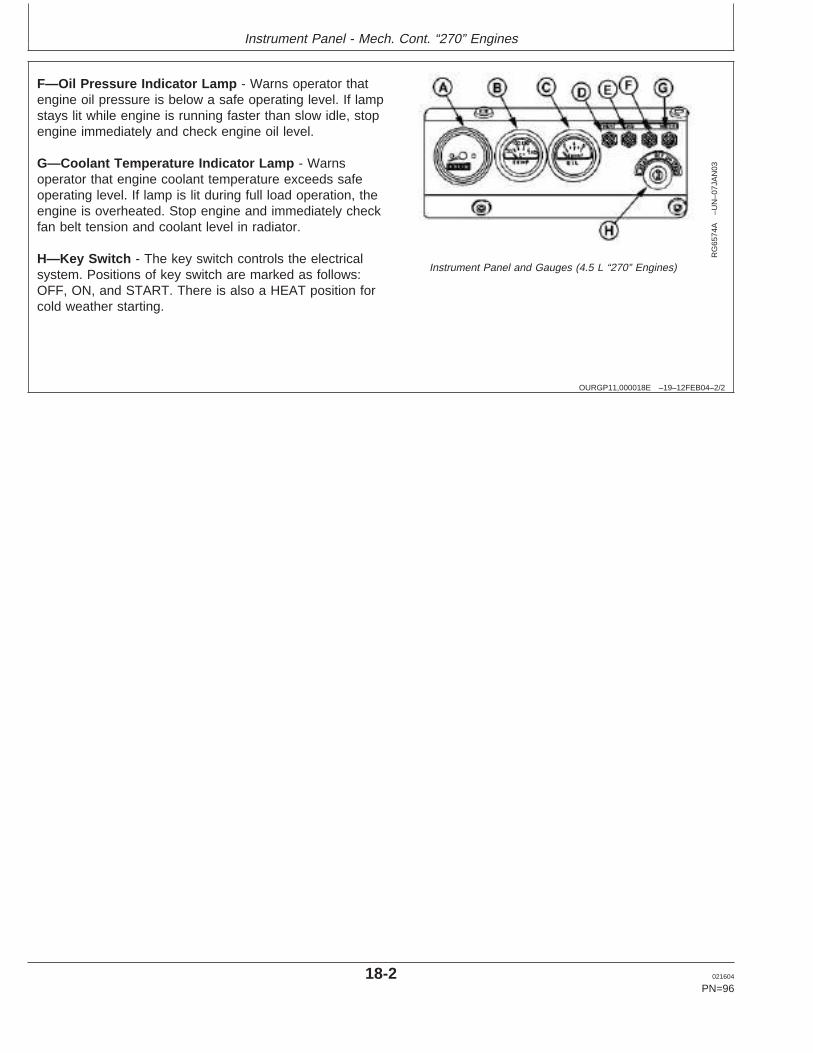
Instrument Panel - Mech. Cont. “270” Engines
OURGP11,000018E –19–12FEB04–2/2
RG
6574
A–U
N–0
7JA
N03
Instrument Panel and Gauges (4.5 L “270” Engines)
F—Oil Pressure Indicator Lamp - Warns operator thatengine oil pressure is below a safe operating level. If lampstays lit while engine is running faster than slow idle, stopengine immediately and check engine oil level.
G—Coolant Temperature Indicator Lamp - Warnsoperator that engine coolant temperature exceeds safeoperating level. If lamp is lit during full load operation, theengine is overheated. Stop engine and immediately checkfan belt tension and coolant level in radiator.
H—Key Switch - The key switch controls the electricalsystem. Positions of key switch are marked as follows:OFF, ON, and START. There is also a HEAT position forcold weather starting.
18-2 021604
PN=96
https://www.truck-manuals.net/
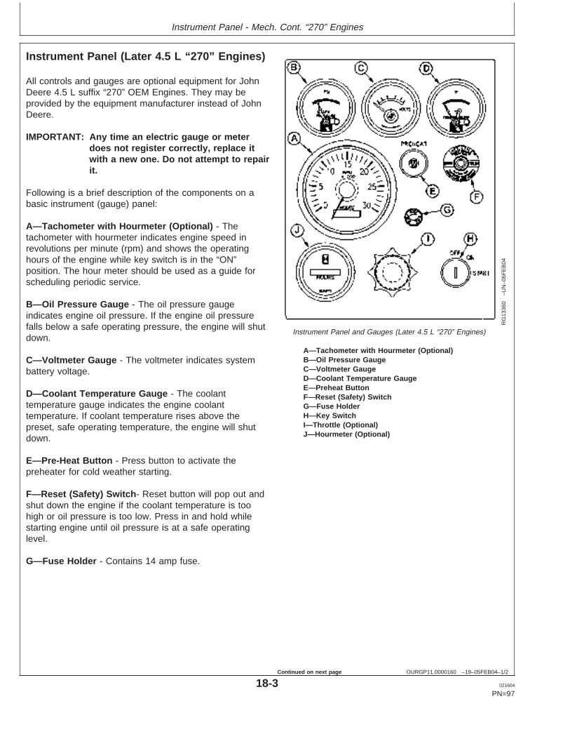
Instrument Panel - Mech. Cont. “270” Engines
OURGP11,0000160 –19–05FEB04–1/2
Instrument Panel (Later 4.5 L “270” Engines)
RG
1336
0–U
N–0
6FE
B04
Instrument Panel and Gauges (Later 4.5 L “270” Engines)
A—Tachometer with Hourmeter (Optional)B—Oil Pressure GaugeC—Voltmeter GaugeD—Coolant Temperature GaugeE—Preheat ButtonF—Reset (Safety) SwitchG—Fuse HolderH—Key SwitchI—Throttle (Optional)J—Hourmeter (Optional)
All controls and gauges are optional equipment for JohnDeere 4.5 L suffix “270” OEM Engines. They may beprovided by the equipment manufacturer instead of JohnDeere.
IMPORTANT: Any time an electric gauge or meterdoes not register correctly, replace itwith a new one. Do not attempt to repairit.
Following is a brief description of the components on abasic instrument (gauge) panel:
A—Tachometer with Hourmeter (Optional) - Thetachometer with hourmeter indicates engine speed inrevolutions per minute (rpm) and shows the operatinghours of the engine while key switch is in the “ON”position. The hour meter should be used as a guide forscheduling periodic service.
B—Oil Pressure Gauge - The oil pressure gaugeindicates engine oil pressure. If the engine oil pressurefalls below a safe operating pressure, the engine will shutdown.
C—Voltmeter Gauge - The voltmeter indicates systembattery voltage.
D—Coolant Temperature Gauge - The coolanttemperature gauge indicates the engine coolanttemperature. If coolant temperature rises above thepreset, safe operating temperature, the engine will shutdown.
E—Pre-Heat Button - Press button to activate thepreheater for cold weather starting.
F—Reset (Safety) Switch - Reset button will pop out andshut down the engine if the coolant temperature is toohigh or oil pressure is too low. Press in and hold whilestarting engine until oil pressure is at a safe operatinglevel.
G—Fuse Holder - Contains 14 amp fuse.
18-3 021604
PN=97
Continued on next page
https://www.truck-manuals.net/
Instrument Panel - Mech. Cont. “270” Engines
OURGP11,0000160 –19–05FEB04–2/2
H—Key Switch - The key switch controls the electricalsystem. Positions of key switch are marked as follows:OFF, ON, and START.
I—Throttle (Optional) - The throttle control is used tocontrol engine speed.
J—Hourmeter (Optional) - The hourmeter indicates theoperating hours of the engine while key switch is in the“ON” position. The hour meter should be used as a guidefor scheduling periodic service.
18-4 021604
PN=98
https://www.truck-manuals.net/
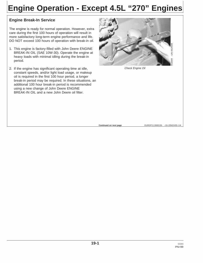
Engine Operation - Except 4.5L “270” Engines
OURGP11,0000135 –19–20NOV03–1/4
Engine Break-In Service
RG
8009
–UN
–06J
AN
99
Check Engine Oil
The engine is ready for normal operation. However, extracare during the first 100 hours of operation will result inmore satisfactory long-term engine performance and life.DO NOT exceed 100 hours of operation with break-in oil.
1. This engine is factory-filled with John Deere ENGINEBREAK-IN OIL (SAE 10W-30). Operate the engine atheavy loads with minimal idling during the break-inperiod.
2. If the engine has significant operating time at idle,constant speeds, and/or light load usage, or makeupoil is required in the first 100 hour period, a longerbreak-in period may be required. In these situations, anadditional 100 hour break-in period is recommendedusing a new change of John Deere ENGINEBREAK-IN OIL and a new John Deere oil filter.
Continued on next page
19-1 021604
PN=99
https://www.truck-manuals.net/
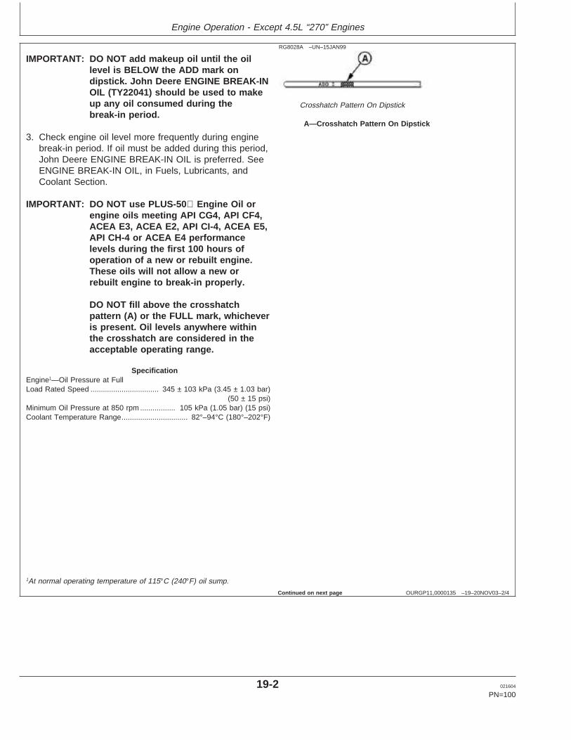
Engine Operation - Except 4.5L “270” Engines
OURGP11,0000135 –19–20NOV03–2/4
RG8028A –UN–15JAN99
Crosshatch Pattern On Dipstick
A—Crosshatch Pattern On Dipstick
IMPORTANT: DO NOT add makeup oil until the oillevel is BELOW the ADD mark ondipstick. John Deere ENGINE BREAK-INOIL (TY22041) should be used to makeup any oil consumed during thebreak-in period.
3. Check engine oil level more frequently during enginebreak-in period. If oil must be added during this period,John Deere ENGINE BREAK-IN OIL is preferred. SeeENGINE BREAK-IN OIL, in Fuels, Lubricants, andCoolant Section.
IMPORTANT: DO NOT use PLUS-50 Engine Oil orengine oils meeting API CG4, API CF4,ACEA E3, ACEA E2, API CI-4, ACEA E5,API CH-4 or ACEA E4 performancelevels during the first 100 hours ofoperation of a new or rebuilt engine.These oils will not allow a new orrebuilt engine to break-in properly.
DO NOT fill above the crosshatchpattern (A) or the FULL mark, whicheveris present. Oil levels anywhere withinthe crosshatch are considered in theacceptable operating range.
SpecificationEngine1—Oil Pressure at FullLoad Rated Speed 345 ± 103 kPa (3.45 ± 1.03 bar)
(50 ± 15 psi).................................
Minimum Oil Pressure at 850 rpm 105 kPa (1.05 bar) (15 psi).................Coolant Temperature Range 82°–94°C (180°–202°F)................................
1At normal operating temperature of 115°C (240°F) oil sump.
Continued on next page
19-2 021604
PN=100
https://www.truck-manuals.net/
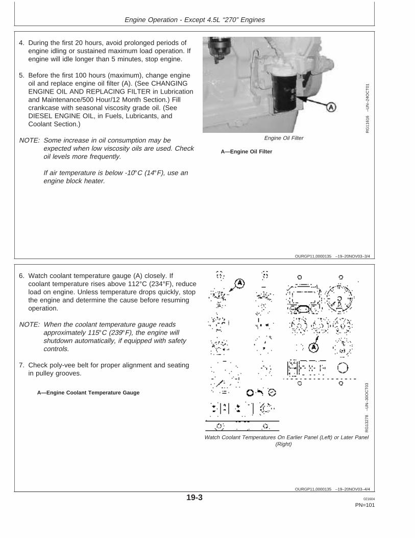
Engine Operation - Except 4.5L “270” Engines
OURGP11,0000135 –19–20NOV03–3/4
RG
1161
6–U
N–2
4OC
T01
Engine Oil Filter
A—Engine Oil Filter
4. During the first 20 hours, avoid prolonged periods ofengine idling or sustained maximum load operation. Ifengine will idle longer than 5 minutes, stop engine.
5. Before the first 100 hours (maximum), change engineoil and replace engine oil filter (A). (See CHANGINGENGINE OIL AND REPLACING FILTER in Lubricationand Maintenance/500 Hour/12 Month Section.) Fillcrankcase with seasonal viscosity grade oil. (SeeDIESEL ENGINE OIL, in Fuels, Lubricants, andCoolant Section.)
NOTE: Some increase in oil consumption may beexpected when low viscosity oils are used. Checkoil levels more frequently.
If air temperature is below -10°C (14°F), use anengine block heater.
OURGP11,0000135 –19–20NOV03–4/4
RG
1327
8–U
N–3
0OC
T03
Watch Coolant Temperatures On Earlier Panel (Left) or Later Panel(Right)
A—Engine Coolant Temperature Gauge
6. Watch coolant temperature gauge (A) closely. Ifcoolant temperature rises above 112°C (234°F), reduceload on engine. Unless temperature drops quickly, stopthe engine and determine the cause before resumingoperation.
NOTE: When the coolant temperature gauge readsapproximately 115°C (239°F), the engine willshutdown automatically, if equipped with safetycontrols.
7. Check poly-vee belt for proper alignment and seatingin pulley grooves.
19-3 021604
PN=101
https://www.truck-manuals.net/
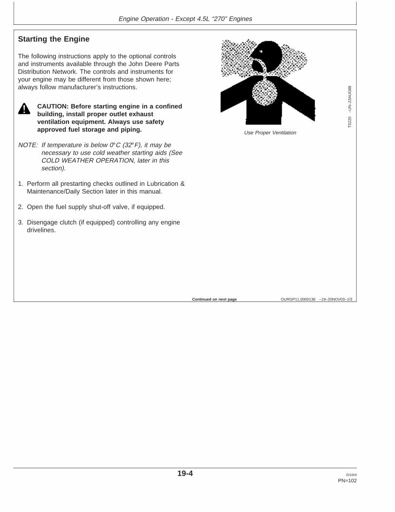
Engine Operation - Except 4.5L “270” Engines
OURGP11,0000136 –19–20NOV03–1/3
Starting the Engine
TS
220
–UN
–23A
UG
88
Use Proper Ventilation
The following instructions apply to the optional controlsand instruments available through the John Deere PartsDistribution Network. The controls and instruments foryour engine may be different from those shown here;always follow manufacturer’s instructions.
CAUTION: Before starting engine in a confinedbuilding, install proper outlet exhaustventilation equipment. Always use safetyapproved fuel storage and piping.
NOTE: If temperature is below 0°C (32°F), it may benecessary to use cold weather starting aids (SeeCOLD WEATHER OPERATION, later in thissection).
1. Perform all prestarting checks outlined in Lubrication &Maintenance/Daily Section later in this manual.
2. Open the fuel supply shut-off valve, if equipped.
3. Disengage clutch (if equipped) controlling any enginedrivelines.
Continued on next page
19-4 021604
PN=102
https://www.truck-manuals.net/
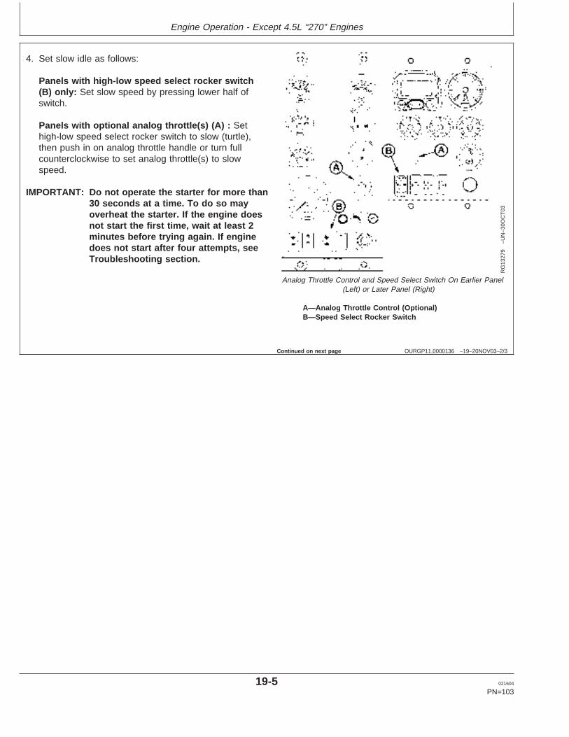
Engine Operation - Except 4.5L “270” Engines
OURGP11,0000136 –19–20NOV03–2/3
RG
1327
9–U
N–3
0OC
T03
Analog Throttle Control and Speed Select Switch On Earlier Panel(Left) or Later Panel (Right)
A—Analog Throttle Control (Optional)B—Speed Select Rocker Switch
4. Set slow idle as follows:
Panels with high-low speed select rocker switch(B) only: Set slow speed by pressing lower half ofswitch.
Panels with optional analog throttle(s) (A) : Sethigh-low speed select rocker switch to slow (turtle),then push in on analog throttle handle or turn fullcounterclockwise to set analog throttle(s) to slowspeed.
IMPORTANT: Do not operate the starter for more than30 seconds at a time. To do so mayoverheat the starter. If the engine doesnot start the first time, wait at least 2minutes before trying again. If enginedoes not start after four attempts, seeTroubleshooting section.
Continued on next page
19-5 021604
PN=103
https://www.truck-manuals.net/
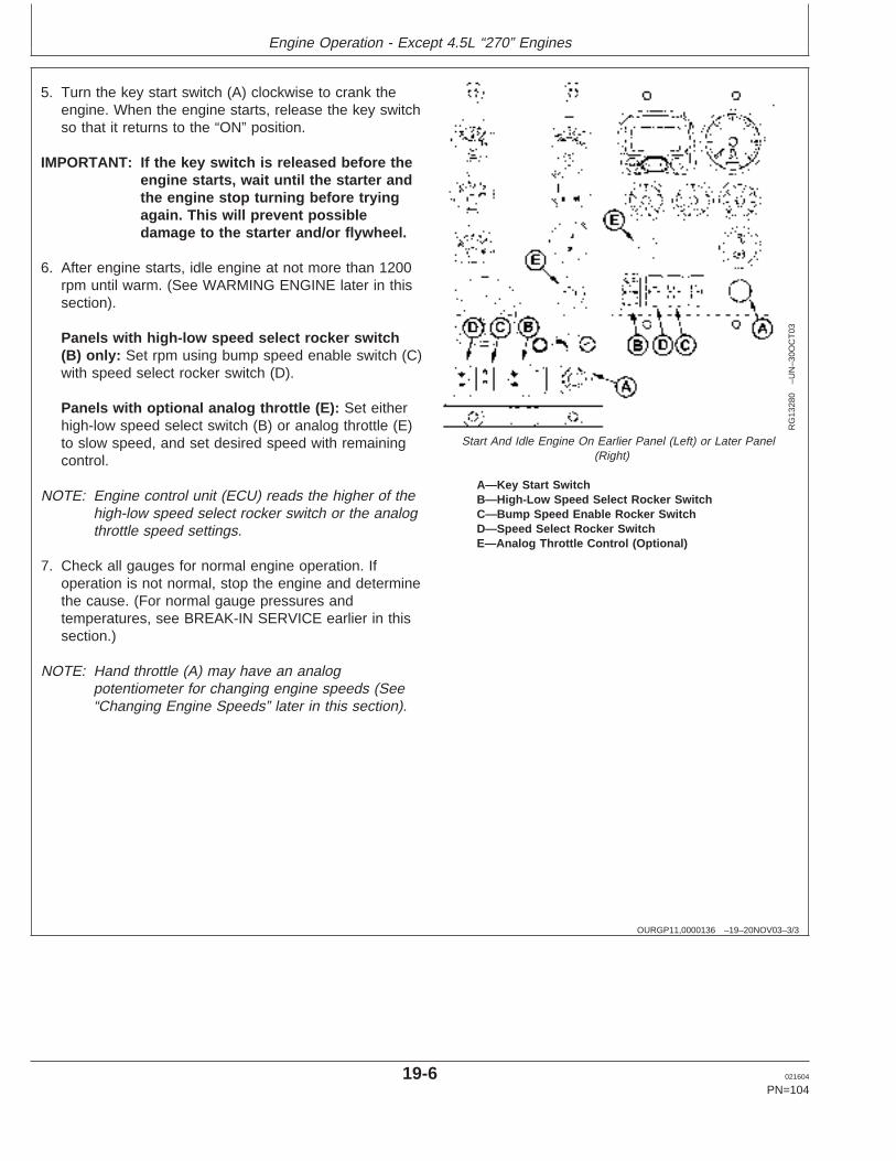
Engine Operation - Except 4.5L “270” Engines
OURGP11,0000136 –19–20NOV03–3/3
RG
1328
0–U
N–3
0OC
T03
Start And Idle Engine On Earlier Panel (Left) or Later Panel(Right)
A—Key Start SwitchB—High-Low Speed Select Rocker SwitchC—Bump Speed Enable Rocker SwitchD—Speed Select Rocker SwitchE—Analog Throttle Control (Optional)
5. Turn the key start switch (A) clockwise to crank theengine. When the engine starts, release the key switchso that it returns to the “ON” position.
IMPORTANT: If the key switch is released before theengine starts, wait until the starter andthe engine stop turning before tryingagain. This will prevent possibledamage to the starter and/or flywheel.
6. After engine starts, idle engine at not more than 1200rpm until warm. (See WARMING ENGINE later in thissection).
Panels with high-low speed select rocker switch(B) only: Set rpm using bump speed enable switch (C)with speed select rocker switch (D).
Panels with optional analog throttle (E): Set eitherhigh-low speed select switch (B) or analog throttle (E)to slow speed, and set desired speed with remainingcontrol.
NOTE: Engine control unit (ECU) reads the higher of thehigh-low speed select rocker switch or the analogthrottle speed settings.
7. Check all gauges for normal engine operation. Ifoperation is not normal, stop the engine and determinethe cause. (For normal gauge pressures andtemperatures, see BREAK-IN SERVICE earlier in thissection.)
NOTE: Hand throttle (A) may have an analogpotentiometer for changing engine speeds (See“Changing Engine Speeds” later in this section).
19-6 021604
PN=104
https://www.truck-manuals.net/
Engine Operation - Except 4.5L “270” Engines
RG,RG34710,5552 –19–20MAY96–1/1
Normal Engine Operation
Observe engine coolant temperature and engine oilpressure. Temperatures and pressures will varybetween engines and with changing operatingconditions, temperatures, and loads.
Normal engine coolant operating temperature range is82°—94°C (180°—202°F). If coolant temperature risesabove 112°C (234°F), reduce load on engine. Unlesstemperature drops quickly, stop engine and determinecause before resuming operation.
Operate the engine under a lighter load and at slowerthan normal speed for first 15 minutes after start-up.DO NOT run engine at slow idle.
IMPORTANT: Should the engine die whileoperating under load, immediately
remove load and restart the engine.Overheating of the turbochargerparts may occur when oil flow isstopped.
Stop engine immediately if there are any signs of partfailure. Symptoms that may be early signs of engineproblems are:
• Sudden drop in oil pressure• Abnormal coolant temperatures• Unusual noise or vibration• Sudden loss of power• Excessive black exhaust• Excessive fuel consumption• Excessive oil consumption• Fluid leaks
19-7 021604
PN=105
https://www.truck-manuals.net/
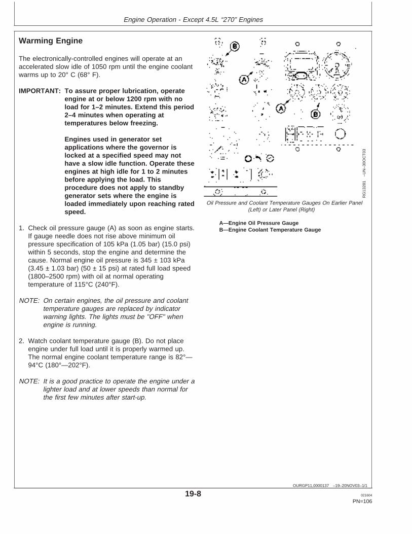
Engine Operation - Except 4.5L “270” Engines
OURGP11,0000137 –19–20NOV03–1/1
Warming Engine
RG
1328
1–U
N–3
0OC
T03
Oil Pressure and Coolant Temperature Gauges On Earlier Panel(Left) or Later Panel (Right)
A—Engine Oil Pressure GaugeB—Engine Coolant Temperature Gauge
The electronically-controlled engines will operate at anaccelerated slow idle of 1050 rpm until the engine coolantwarms up to 20° C (68° F).
IMPORTANT: To assure proper lubrication, operateengine at or below 1200 rpm with noload for 1–2 minutes. Extend this period2–4 minutes when operating attemperatures below freezing.
Engines used in generator setapplications where the governor islocked at a specified speed may nothave a slow idle function. Operate theseengines at high idle for 1 to 2 minutesbefore applying the load. Thisprocedure does not apply to standbygenerator sets where the engine isloaded immediately upon reaching ratedspeed.
1. Check oil pressure gauge (A) as soon as engine starts.If gauge needle does not rise above minimum oilpressure specification of 105 kPa (1.05 bar) (15.0 psi)within 5 seconds, stop the engine and determine thecause. Normal engine oil pressure is 345 ± 103 kPa(3.45 ± 1.03 bar) (50 ± 15 psi) at rated full load speed(1800–2500 rpm) with oil at normal operatingtemperature of 115°C (240°F).
NOTE: On certain engines, the oil pressure and coolanttemperature gauges are replaced by indicatorwarning lights. The lights must be "OFF" whenengine is running.
2. Watch coolant temperature gauge (B). Do not placeengine under full load until it is properly warmed up.The normal engine coolant temperature range is 82°—94°C (180°—202°F).
NOTE: It is a good practice to operate the engine under alighter load and at lower speeds than normal forthe first few minutes after start-up.
19-8 021604
PN=106
https://www.truck-manuals.net/
Engine Operation - Except 4.5L “270” Engines
RG,RG34710,5050 –19–25FEB03–1/2
Cold Weather Operation
TS
1356
–UN
–18M
AR
92
Handle Starting Fluid with Care
RG
1152
1–1
9–10
JAN
01
Cold Weather Starting Guidelines
CAUTION: DO NOT use starting fluid onengines equipped with air intake heaters orglow plugs. Ether injector starting fluid is highlyflammable and may explode, causing seriousinjury.
DO NOT use starting fluid near fire, sparks, orflames. DO NOT incinerate or puncture astarting fluid container.
Engines may be equipped with intake air heaters, coolantheaters, fuel heaters, or ether injectors as cold weatherstarting aids. Later “475” 4-valve cylinder head enginesare equipped with glow plugs as an automatic coldweather starting aid.
Starting aids are required below 0°C (32°F). They willenhance starting performance above these temperaturesand may be needed to start applications that have highparasitic loads during cranking and/or start acceleration toidle.
Using correct grade of oil (per engine and machineoperator’s manual) is critical to achieving adequate coldweather cranking speed.
Other cold weather starting aids are required attemperatures below -30°C (-22°F) or at altitudes above1500 m (5000 ft).
1. Follow steps 1—4 as listed under STARTING THEENGINE, earlier in this section, then proceed asfollows according to the instrument (gauge) panel onyour engine.
2. 275-Series Engines Without Air Intake Heaters:Manually activate ether injectors.
Continued on next page
19-9 021604
PN=107
https://www.truck-manuals.net/
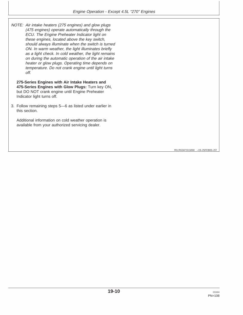
Engine Operation - Except 4.5L “270” Engines
RG,RG34710,5050 –19–25FEB03–2/2
NOTE: Air intake heaters (275 engines) and glow plugs(475 engines) operate automatically through theECU. The Engine Preheater Indicator light onthese engines, located above the key switch,should always illuminate when the switch is turnedON. In warm weather, the light illuminates brieflyas a light check. In cold weather, the light remainson during the automatic operation of the air intakeheater or glow plugs. Operating time depends ontemperature. Do not crank engine until light turnsoff.
275-Series Engines with Air Intake Heaters and475-Series Engines with Glow Plugs: Turn key ON,but DO NOT crank engine until Engine PreheaterIndicator light turns off.
3. Follow remaining steps 5—6 as listed under earlier inthis section.
Additional information on cold weather operation isavailable from your authorized servicing dealer.
19-10 021604
PN=108
https://www.truck-manuals.net/

Engine Operation - Except 4.5L “270” Engines
RG,RG34710,5564 –19–20MAY96–1/2
Using a Booster Battery or Charger
TS
204
–UN
–23A
UG
88
Exploding Battery
RG
4678
–UN
–14D
EC
88
12-Volt System
RG
4698
–UN
–14D
EC
88
24-Volt System
A—12-Volt Machine Battery (ies)B—12-Volt Booster Battery (ies)C—Booster CableD—Cable to Starting Motor
A 12-volt booster battery can be connected in parallel withbattery (ies) on the unit to aid in cold weather starting.ALWAYS use heavy duty jumper cables.
CAUTION: Gas given off by battery is explosive.Keep sparks and flames away from battery.Before connecting or disconnecting a batterycharger, turn charger off. Make last connectionand first disconnection at a point away frombattery. Always connect NEGATIVE (–) cablelast and disconnect this cable first.
WARNING: Battery posts, terminals, and relatedaccessories contain lead and lead compounds, chemicalsknown to the State of California to cause cancer andreproductive harm. Wash hands after handling.
IMPORTANT: Be sure polarity is correct beforemaking connections. Reversed polaritywill damage electrical system. Alwaysconnect positive to positive andnegative to ground. Always use 12-voltbooster battery for 12-volt electricalsystems and 24-volt booster battery(ies) for 24-volt electrical systems.
1. Connect booster battery or batteries to produce therequired system voltage for your engine application.
NOTE: To avoid sparks, DO NOT allow the free ends ofjumper cables to touch the engine.
2. Connect one end of jumper cable to the POSITIVE (+)post of the booster battery.
3. Connect the other end of the jumper cable to thePOSITIVE (+) post of battery connected to starter.
4. Connect one end of the other jumper cable to theNEGATIVE (–) post of the booster battery.
5. ALWAYS complete the hookup by making the lastconnection of the NEGATIVE (–) cable to a goodground on the engine frame and away from the battery(ies).
19-11 021604
PN=109
Continued on next page
https://www.truck-manuals.net/
Engine Operation - Except 4.5L “270” Engines
RG,RG34710,5564 –19–20MAY96–2/2
6. Start the engine. Disconnect jumper cablesimmediately after engine starts. Disconnect NEGATIVE(–) cable first.
RG,RG34710,5562 –19–20MAY96–1/1
Avoid Excessive Engine Idling
Prolonged idling may cause the engine coolanttemperature to fall below its normal range. This, inturn, causes crankcase oil dilution, due to incompletefuel combustion, and permits formation of gummydeposits on valves, pistons, and piston rings. It alsopromotes rapid accumulation of engine sludge andunburned fuel in the exhaust system.
Once an engine is warmed to normal operatingtemperatures, engine should be idled at slow idle
speed. Slow idle speed for this engine is 850 rpm atfactory. If an engine will be idling for more than 5minutes, stop and restart later.
NOTE: Generator set applications where the governoris locked at a specified speed may not have aslow idle function. These engines will idle at noload governed speed (high idle).
19-12 021604
PN=110
https://www.truck-manuals.net/
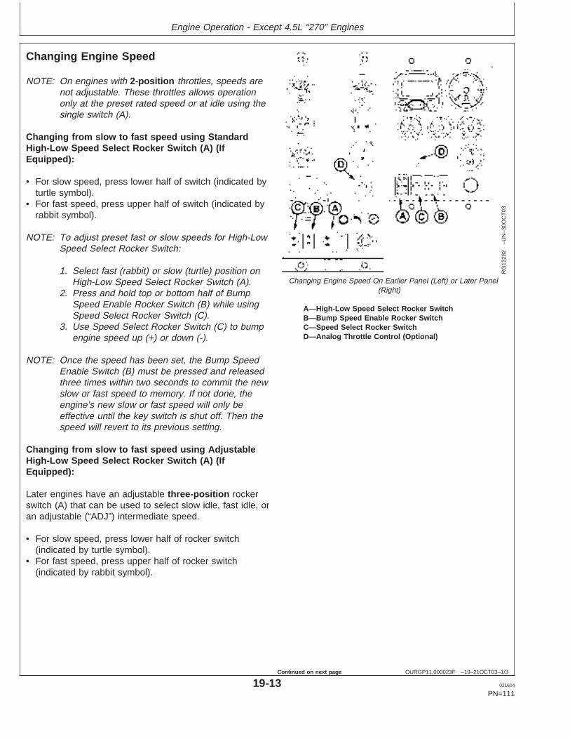
Engine Operation - Except 4.5L “270” Engines
OURGP11,000023F –19–21OCT03–1/3
Changing Engine Speed
RG
1328
2–U
N–3
0OC
T03
Changing Engine Speed On Earlier Panel (Left) or Later Panel(Right)
A—High-Low Speed Select Rocker SwitchB—Bump Speed Enable Rocker SwitchC—Speed Select Rocker SwitchD—Analog Throttle Control (Optional)
NOTE: On engines with 2-position throttles, speeds arenot adjustable. These throttles allows operationonly at the preset rated speed or at idle using thesingle switch (A).
Changing from slow to fast speed using StandardHigh-Low Speed Select Rocker Switch (A) (IfEquipped):
• For slow speed, press lower half of switch (indicated byturtle symbol).
• For fast speed, press upper half of switch (indicated byrabbit symbol).
NOTE: To adjust preset fast or slow speeds for High-LowSpeed Select Rocker Switch:
1. Select fast (rabbit) or slow (turtle) position onHigh-Low Speed Select Rocker Switch (A).
2. Press and hold top or bottom half of BumpSpeed Enable Rocker Switch (B) while usingSpeed Select Rocker Switch (C).
3. Use Speed Select Rocker Switch (C) to bumpengine speed up (+) or down (-).
NOTE: Once the speed has been set, the Bump SpeedEnable Switch (B) must be pressed and releasedthree times within two seconds to commit the newslow or fast speed to memory. If not done, theengine’s new slow or fast speed will only beeffective until the key switch is shut off. Then thespeed will revert to its previous setting.
Changing from slow to fast speed using AdjustableHigh-Low Speed Select Rocker Switch (A) (IfEquipped):
Later engines have an adjustable three-position rockerswitch (A) that can be used to select slow idle, fast idle, oran adjustable (“ADJ”) intermediate speed.
• For slow speed, press lower half of rocker switch(indicated by turtle symbol).
• For fast speed, press upper half of rocker switch(indicated by rabbit symbol).
19-13 021604
PN=111
Continued on next page
https://www.truck-manuals.net/
Engine Operation - Except 4.5L “270” Engines
OURGP11,000023F –19–21OCT03–2/3
NOTE: To adjust preset fast or slow speeds withadjustable High-Low Speed Select Rocker Switch:
1. Select middle position (ADJ) or slow (turtle)position on the optional Adjustable Three-StateSpeed Select Rocker Switch (A).
2. Press and hold top or bottom half of BumpSpeed Enable Rocker Switch (B) while usingSpeed Select Rocker Switch (C).
3. Use Speed Select Rocker Switch (C) to bumpengine speed up (+) or down (-).
NOTE: Slow (turtle) position is factory preset at lowengine idle, while middle (ADJ) position is factoryset at high engine idle.
NOTE: Once the speed has been set, the Bump SpeedEnable Switch (B) must be pressed and releasedthree times within two seconds to commit the newslow or fast speed to memory. If not done, theengine’s new slow or fast speed will only beeffective until the key is shut off. Then the speedwill revert to its previous setting.
Changing engine speed using optional analogpotentiometer throttle (D)
NOTE: Pushing in on analog potentiometer willimmediately take engine to slow idle speed.
1. Set High-Low Speed Select Rocker Switch (A) to lowspeed position.
2. Turn potentiometer throttle clockwise to increase speedor counterclockwise to decrease speed.
NOTE: Engine Control Unit (ECU) reads the higher of theHigh-Low Speed Select Rocker Switch or theAnalog Throttle(s) Speed Settings. With High-Lowswitch at low speed, Analog Throttle(s) will controlspeed higher than low idle setting.
Continued on next page
19-14 021604
PN=112
https://www.truck-manuals.net/
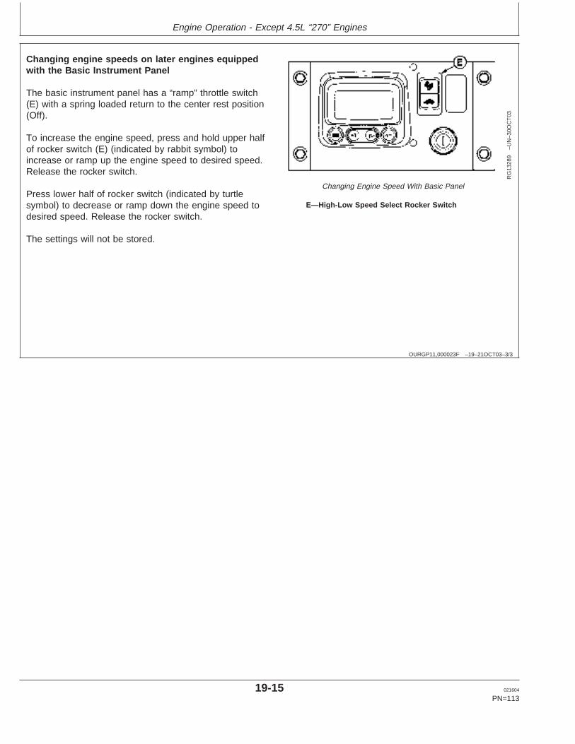
Engine Operation - Except 4.5L “270” Engines
OURGP11,000023F –19–21OCT03–3/3
RG
1328
9–U
N–3
0OC
T03
Changing Engine Speed With Basic Panel
E—High-Low Speed Select Rocker Switch
Changing engine speeds on later engines equippedwith the Basic Instrument Panel
The basic instrument panel has a “ramp” throttle switch(E) with a spring loaded return to the center rest position(Off).
To increase the engine speed, press and hold upper halfof rocker switch (E) (indicated by rabbit symbol) toincrease or ramp up the engine speed to desired speed.Release the rocker switch.
Press lower half of rocker switch (indicated by turtlesymbol) to decrease or ramp down the engine speed todesired speed. Release the rocker switch.
The settings will not be stored.
19-15 021604
PN=113
https://www.truck-manuals.net/
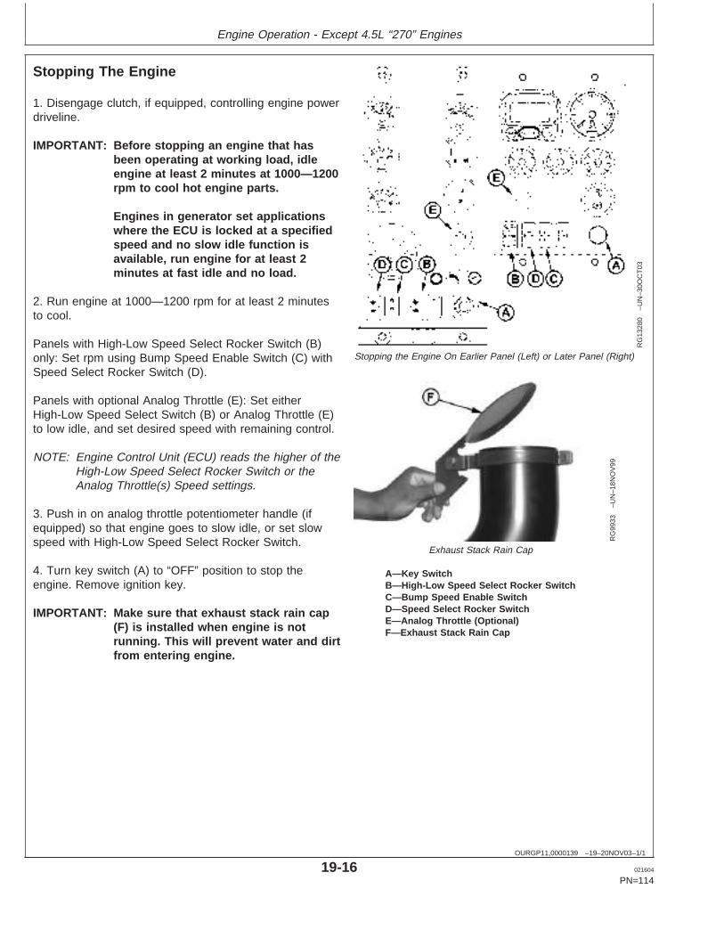
Engine Operation - Except 4.5L “270” Engines
OURGP11,0000139 –19–20NOV03–1/1
Stopping The Engine
RG
1328
0–U
N–3
0OC
T03
Stopping the Engine On Earlier Panel (Left) or Later Panel (Right)
RG
9933
–UN
–18N
OV
99
Exhaust Stack Rain Cap
A—Key SwitchB—High-Low Speed Select Rocker SwitchC—Bump Speed Enable SwitchD—Speed Select Rocker SwitchE—Analog Throttle (Optional)F—Exhaust Stack Rain Cap
1. Disengage clutch, if equipped, controlling engine powerdriveline.
IMPORTANT: Before stopping an engine that hasbeen operating at working load, idleengine at least 2 minutes at 1000—1200rpm to cool hot engine parts.
Engines in generator set applicationswhere the ECU is locked at a specifiedspeed and no slow idle function isavailable, run engine for at least 2minutes at fast idle and no load.
2. Run engine at 1000—1200 rpm for at least 2 minutesto cool.
Panels with High-Low Speed Select Rocker Switch (B)only: Set rpm using Bump Speed Enable Switch (C) withSpeed Select Rocker Switch (D).
Panels with optional Analog Throttle (E): Set eitherHigh-Low Speed Select Switch (B) or Analog Throttle (E)to low idle, and set desired speed with remaining control.
NOTE: Engine Control Unit (ECU) reads the higher of theHigh-Low Speed Select Rocker Switch or theAnalog Throttle(s) Speed settings.
3. Push in on analog throttle potentiometer handle (ifequipped) so that engine goes to slow idle, or set slowspeed with High-Low Speed Select Rocker Switch.
4. Turn key switch (A) to “OFF” position to stop theengine. Remove ignition key.
IMPORTANT: Make sure that exhaust stack rain cap(F) is installed when engine is notrunning. This will prevent water and dirtfrom entering engine.
19-16 021604
PN=114
https://www.truck-manuals.net/
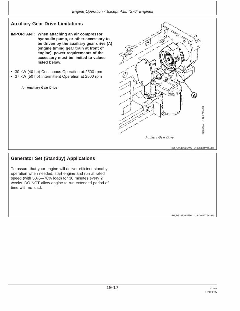
Engine Operation - Except 4.5L “270” Engines
RG,RG34710,5555 –19–20MAY96–1/1
Auxiliary Gear Drive Limitations
RG
7634
A–U
N–2
2JA
N99
Auxiliary Gear Drive
A—Auxiliary Gear Drive
IMPORTANT: When attaching an air compressor,hydraulic pump, or other accessory tobe driven by the auxiliary gear drive (A)(engine timing gear train at front ofengine), power requirements of theaccessory must be limited to valueslisted below:
• 30 kW (40 hp) Continuous Operation at 2500 rpm• 37 kW (50 hp) Intermittent Operation at 2500 rpm
RG,RG34710,5556 –19–20MAY96–1/1
Generator Set (Standby) Applications
To assure that your engine will deliver efficient standbyoperation when needed, start engine and run at ratedspeed (with 50%—70% load) for 30 minutes every 2weeks. DO NOT allow engine to run extended period oftime with no load.
19-17 021604
PN=115
https://www.truck-manuals.net/
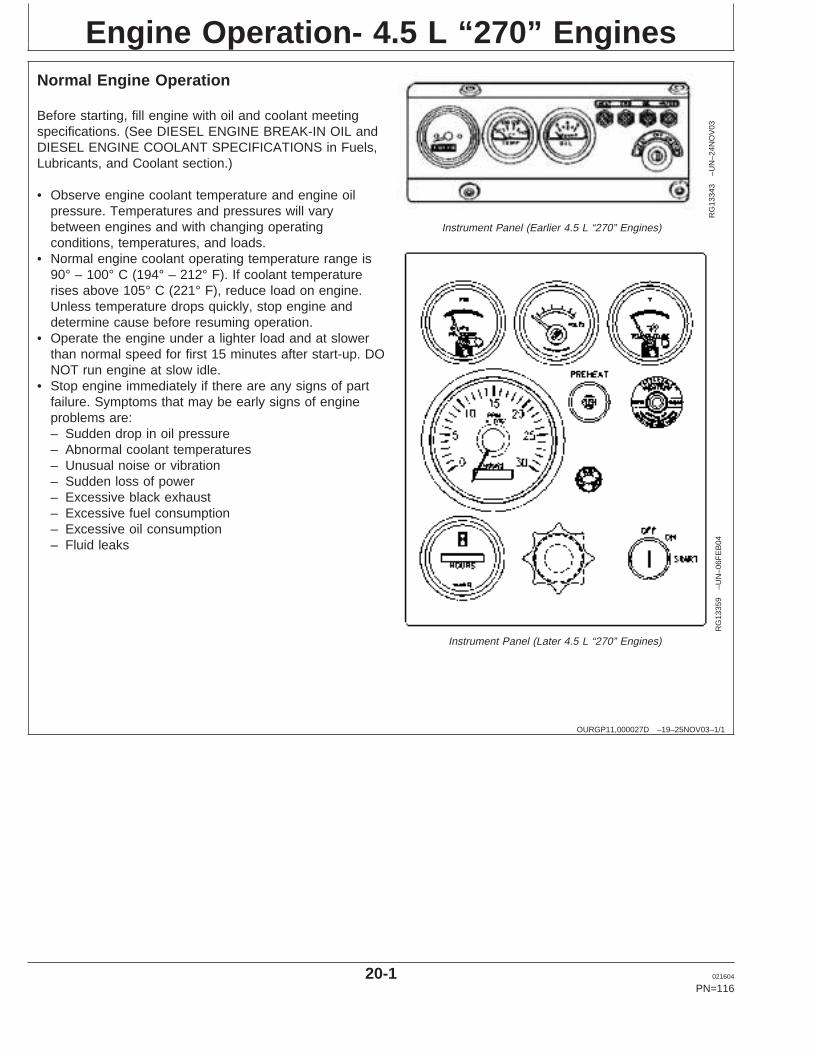
Engine Operation- 4.5 L “270” Engines
OURGP11,000027D –19–25NOV03–1/1
Normal Engine Operation
RG
1334
3–U
N–2
4NO
V03
Instrument Panel (Earlier 4.5 L “270” Engines)
RG
1335
9–U
N–0
6FE
B04
Instrument Panel (Later 4.5 L “270” Engines)
Before starting, fill engine with oil and coolant meetingspecifications. (See DIESEL ENGINE BREAK-IN OIL andDIESEL ENGINE COOLANT SPECIFICATIONS in Fuels,Lubricants, and Coolant section.)
• Observe engine coolant temperature and engine oilpressure. Temperatures and pressures will varybetween engines and with changing operatingconditions, temperatures, and loads.
• Normal engine coolant operating temperature range is90° – 100° C (194° – 212° F). If coolant temperaturerises above 105° C (221° F), reduce load on engine.Unless temperature drops quickly, stop engine anddetermine cause before resuming operation.
• Operate the engine under a lighter load and at slowerthan normal speed for first 15 minutes after start-up. DONOT run engine at slow idle.
• Stop engine immediately if there are any signs of partfailure. Symptoms that may be early signs of engineproblems are:– Sudden drop in oil pressure– Abnormal coolant temperatures– Unusual noise or vibration– Sudden loss of power– Excessive black exhaust– Excessive fuel consumption– Excessive oil consumption– Fluid leaks
20-1 021604
PN=116
https://www.truck-manuals.net/
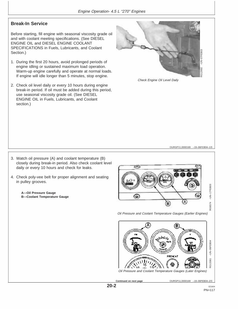
Engine Operation- 4.5 L “270” Engines
OURGP11,0000169 –19–06FEB04–1/3
Break-In Service
RG
1269
2–U
N–0
7FE
B03
Check Engine Oil Level Daily
Before starting, fill engine with seasonal viscosity grade oiland with coolant meeting specifications. (See DIESELENGINE OIL and DIESEL ENGINE COOLANTSPECIFICATIONS in Fuels, Lubricants, and CoolantSection.)
1. During the first 20 hours, avoid prolonged periods ofengine idling or sustained maximum load operation.Warm-up engine carefully and operate at normal loads.If engine will idle longer than 5 minutes, stop engine.
2. Check oil level daily or every 10 hours during enginebreak-in period. If oil must be added during this period,use seasonal viscosity grade oil. (See DIESELENGINE OIL in Fuels, Lubricants, and Coolantsection.)
OURGP11,0000169 –19–06FEB04–2/3
RG
6574
–UN
–17F
EB
03Oil Pressure and Coolant Temperature Gauges (Earlier Engines)
RG
1336
1–U
N–0
6FE
B04
Oil Pressure and Coolant Temperature Gauges (Later Engines)
A—Oil Pressure GaugeB—Coolant Temperature Gauge
3. Watch oil pressure (A) and coolant temperature (B)closely during break-in period. Also check coolant leveldaily or every 10 hours and check for leaks.
4. Check poly-vee belt for proper alignment and seatingin pulley grooves.
20-2 021604
PN=117
Continued on next page
https://www.truck-manuals.net/
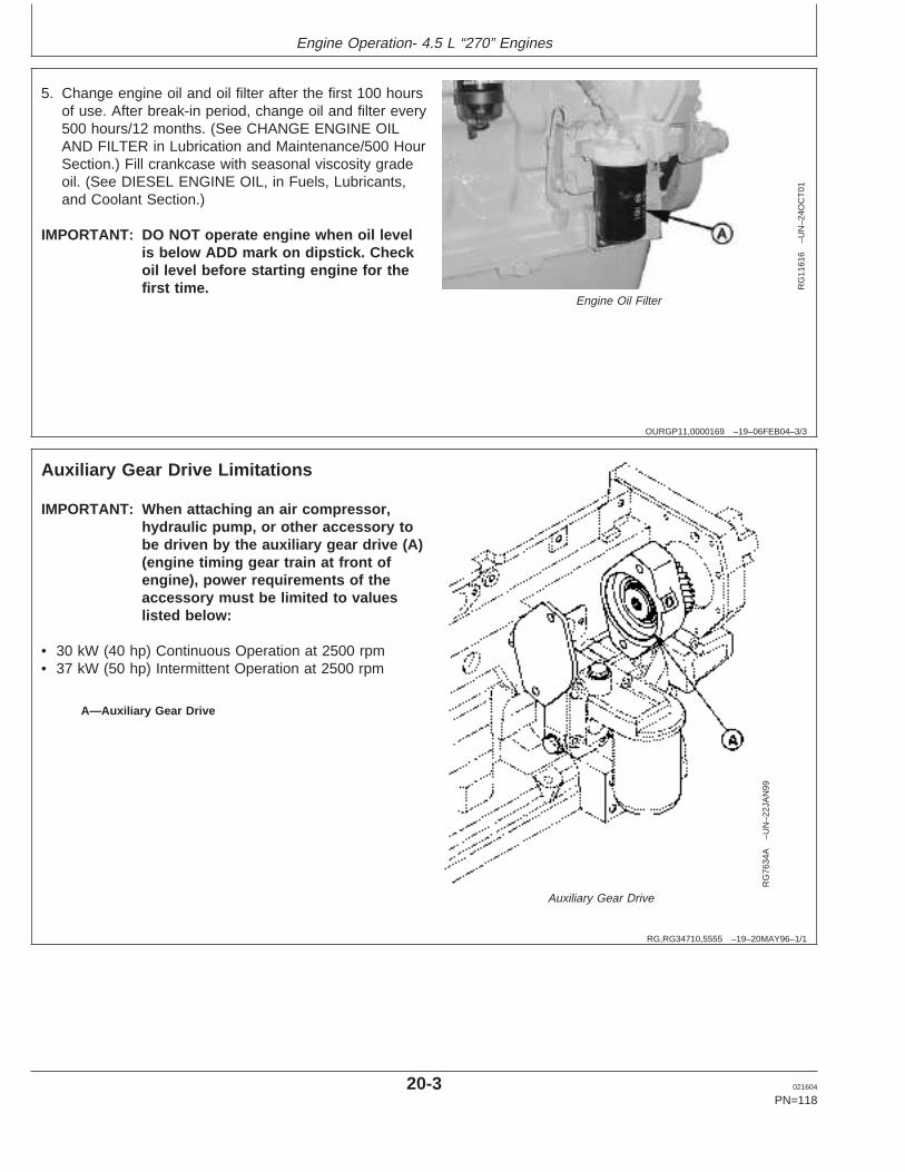
Engine Operation- 4.5 L “270” Engines
OURGP11,0000169 –19–06FEB04–3/3
RG
1161
6–U
N–2
4OC
T01
Engine Oil Filter
5. Change engine oil and oil filter after the first 100 hoursof use. After break-in period, change oil and filter every500 hours/12 months. (See CHANGE ENGINE OILAND FILTER in Lubrication and Maintenance/500 HourSection.) Fill crankcase with seasonal viscosity gradeoil. (See DIESEL ENGINE OIL, in Fuels, Lubricants,and Coolant Section.)
IMPORTANT: DO NOT operate engine when oil levelis below ADD mark on dipstick. Checkoil level before starting engine for thefirst time.
RG,RG34710,5555 –19–20MAY96–1/1
Auxiliary Gear Drive Limitations
RG
7634
A–U
N–2
2JA
N99
Auxiliary Gear Drive
A—Auxiliary Gear Drive
IMPORTANT: When attaching an air compressor,hydraulic pump, or other accessory tobe driven by the auxiliary gear drive (A)(engine timing gear train at front ofengine), power requirements of theaccessory must be limited to valueslisted below:
• 30 kW (40 hp) Continuous Operation at 2500 rpm• 37 kW (50 hp) Intermittent Operation at 2500 rpm
20-3 021604
PN=118
https://www.truck-manuals.net/
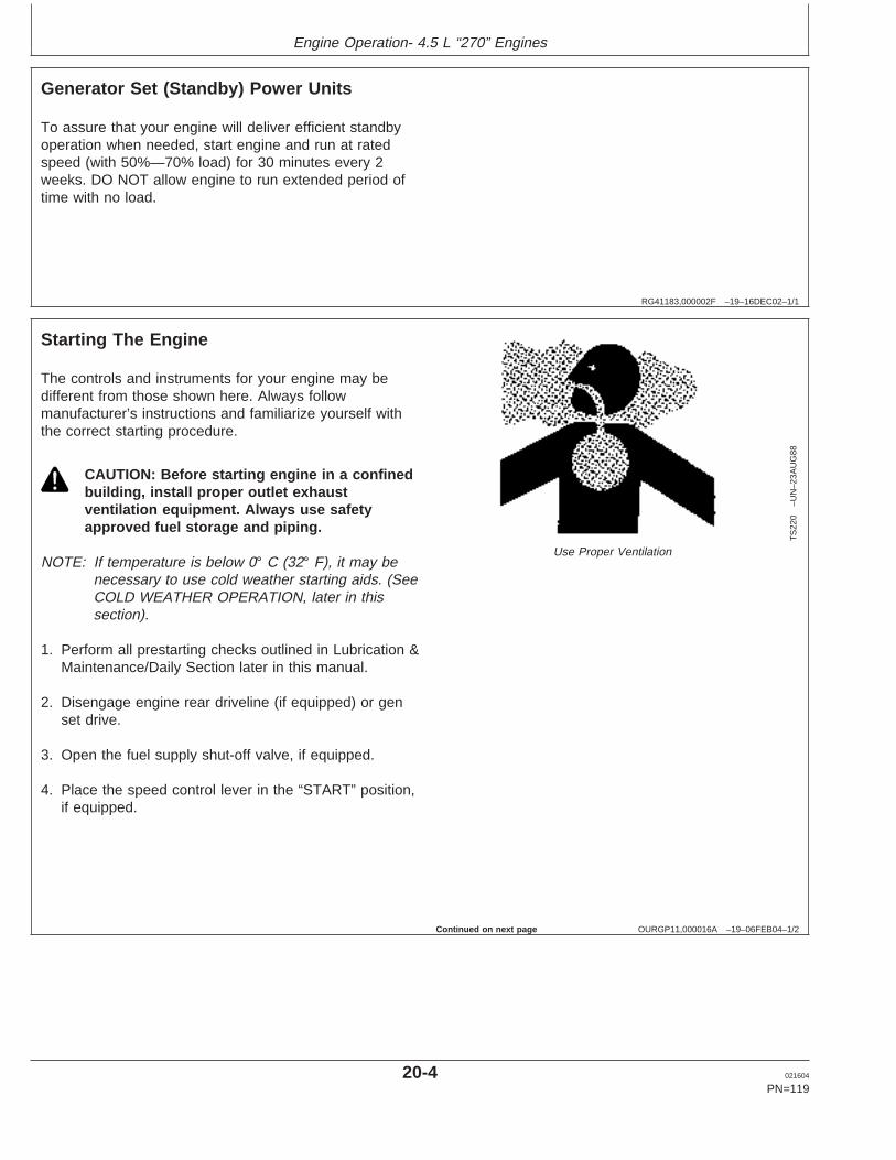
Engine Operation- 4.5 L “270” Engines
RG41183,000002F –19–16DEC02–1/1
Generator Set (Standby) Power Units
To assure that your engine will deliver efficient standbyoperation when needed, start engine and run at ratedspeed (with 50%—70% load) for 30 minutes every 2weeks. DO NOT allow engine to run extended period oftime with no load.
OURGP11,000016A –19–06FEB04–1/2
Starting The Engine
TS
220
–UN
–23A
UG
88
Use Proper Ventilation
The controls and instruments for your engine may bedifferent from those shown here. Always followmanufacturer’s instructions and familiarize yourself withthe correct starting procedure.
CAUTION: Before starting engine in a confinedbuilding, install proper outlet exhaustventilation equipment. Always use safetyapproved fuel storage and piping.
NOTE: If temperature is below 0° C (32° F), it may benecessary to use cold weather starting aids. (SeeCOLD WEATHER OPERATION, later in thissection).
1. Perform all prestarting checks outlined in Lubrication &Maintenance/Daily Section later in this manual.
2. Disengage engine rear driveline (if equipped) or genset drive.
3. Open the fuel supply shut-off valve, if equipped.
4. Place the speed control lever in the “START” position,if equipped.
Continued on next page
20-4 021604
PN=119
https://www.truck-manuals.net/
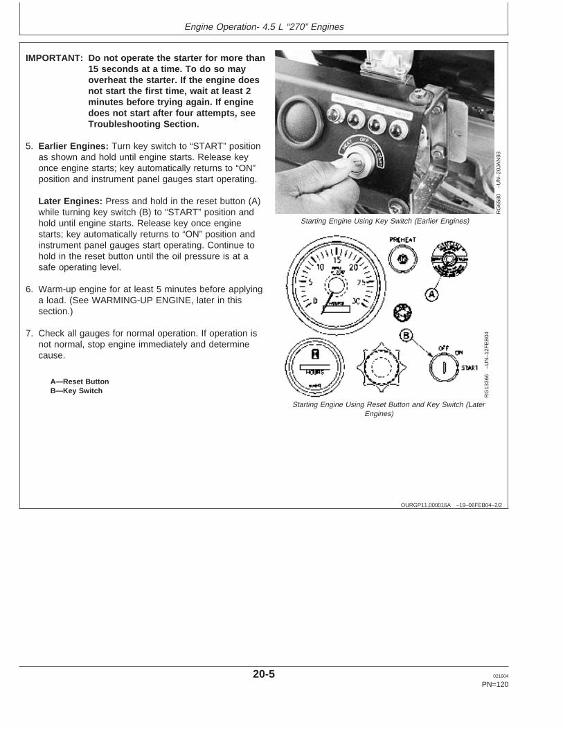
Engine Operation- 4.5 L “270” Engines
OURGP11,000016A –19–06FEB04–2/2R
G65
80–U
N–2
0JA
N93
Starting Engine Using Key Switch (Earlier Engines)
RG
1336
6–U
N–1
2FE
B04
Starting Engine Using Reset Button and Key Switch (LaterEngines)
A—Reset ButtonB—Key Switch
IMPORTANT: Do not operate the starter for more than15 seconds at a time. To do so mayoverheat the starter. If the engine doesnot start the first time, wait at least 2minutes before trying again. If enginedoes not start after four attempts, seeTroubleshooting Section.
5. Earlier Engines: Turn key switch to “START” positionas shown and hold until engine starts. Release keyonce engine starts; key automatically returns to “ON”position and instrument panel gauges start operating.
Later Engines: Press and hold in the reset button (A)while turning key switch (B) to “START” position andhold until engine starts. Release key once enginestarts; key automatically returns to “ON” position andinstrument panel gauges start operating. Continue tohold in the reset button until the oil pressure is at asafe operating level.
6. Warm-up engine for at least 5 minutes before applyinga load. (See WARMING-UP ENGINE, later in thissection.)
7. Check all gauges for normal operation. If operation isnot normal, stop engine immediately and determinecause.
20-5 021604
PN=120
https://www.truck-manuals.net/
Engine Operation- 4.5 L “270” Engines
OURGP11,000018A –19–10FEB04–1/2
Cold Weather Starting
When outside temperatures fall below 0°C (32° F) it maybe necessary to consider using cold weather starting aids.
Your PowerTech Engines may be fitted with a blockheater, glow plugs, air intake heater and increasedcapacity battery and/or lower viscosity oil may also beused. See your local John Deere engine distributor orservicing dealer for recommendations.
1. Perform all prestarting checks outlined in Lubrication &Maintenance/Daily Section later in this manual.
2. Disengage engine rear driveline (if equipped) or genset drive.
3. Open the fuel supply shut-off valve, if equipped.
4. Place the speed control lever in the “START” position,if equipped.
POWERTECH is a trademark of Deere & Company Continued on next page
20-6 021604
PN=121
https://www.truck-manuals.net/
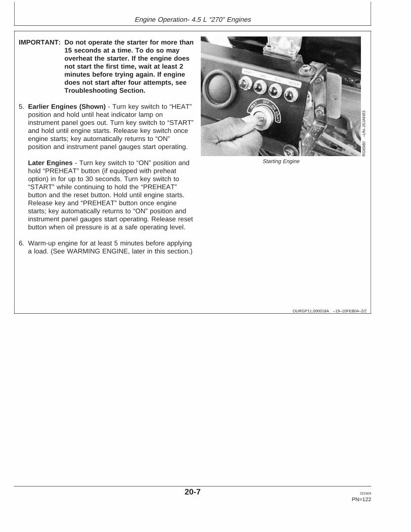
Engine Operation- 4.5 L “270” Engines
OURGP11,000018A –19–10FEB04–2/2
RG
6580
–UN
–20J
AN
93
Starting Engine
IMPORTANT: Do not operate the starter for more than15 seconds at a time. To do so mayoverheat the starter. If the engine doesnot start the first time, wait at least 2minutes before trying again. If enginedoes not start after four attempts, seeTroubleshooting Section.
5. Earlier Engines (Shown) - Turn key switch to “HEAT”position and hold until heat indicator lamp oninstrument panel goes out. Turn key switch to “START”and hold until engine starts. Release key switch onceengine starts; key automatically returns to “ON”position and instrument panel gauges start operating.
Later Engines - Turn key switch to “ON” position andhold “PREHEAT” button (if equipped with preheatoption) in for up to 30 seconds. Turn key switch to“START” while continuing to hold the “PREHEAT”button and the reset button. Hold until engine starts.Release key and “PREHEAT” button once enginestarts; key automatically returns to “ON” position andinstrument panel gauges start operating. Release resetbutton when oil pressure is at a safe operating level.
6. Warm-up engine for at least 5 minutes before applyinga load. (See WARMING ENGINE, later in this section.)
20-7 021604
PN=122
https://www.truck-manuals.net/
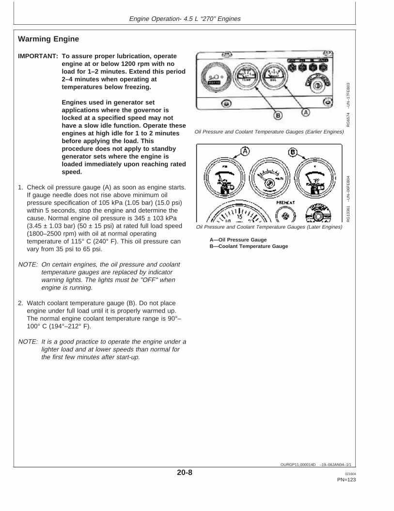
Engine Operation- 4.5 L “270” Engines
OURGP11,000014D –19–06JAN04–1/1
Warming Engine
RG
6574
–UN
–17F
EB
03
Oil Pressure and Coolant Temperature Gauges (Earlier Engines)
RG
1336
1–U
N–0
6FE
B04
Oil Pressure and Coolant Temperature Gauges (Later Engines)
A—Oil Pressure GaugeB—Coolant Temperature Gauge
IMPORTANT: To assure proper lubrication, operateengine at or below 1200 rpm with noload for 1–2 minutes. Extend this period2–4 minutes when operating attemperatures below freezing.
Engines used in generator setapplications where the governor islocked at a specified speed may nothave a slow idle function. Operate theseengines at high idle for 1 to 2 minutesbefore applying the load. Thisprocedure does not apply to standbygenerator sets where the engine isloaded immediately upon reaching ratedspeed.
1. Check oil pressure gauge (A) as soon as engine starts.If gauge needle does not rise above minimum oilpressure specification of 105 kPa (1.05 bar) (15.0 psi)within 5 seconds, stop the engine and determine thecause. Normal engine oil pressure is 345 ± 103 kPa(3.45 ± 1.03 bar) (50 ± 15 psi) at rated full load speed(1800–2500 rpm) with oil at normal operatingtemperature of 115° C (240° F). This oil pressure canvary from 35 psi to 65 psi.
NOTE: On certain engines, the oil pressure and coolanttemperature gauges are replaced by indicatorwarning lights. The lights must be "OFF" whenengine is running.
2. Watch coolant temperature gauge (B). Do not placeengine under full load until it is properly warmed up.The normal engine coolant temperature range is 90°–100° C (194°–212° F).
NOTE: It is a good practice to operate the engine under alighter load and at lower speeds than normal forthe first few minutes after start-up.
20-8 021604
PN=123
https://www.truck-manuals.net/
Engine Operation- 4.5 L “270” Engines
RG41183,0000034 –19–16DEC02–1/1
Avoid Excessive Engine Idling
Avoid excessive engine idling. Prolonged idling may causethe engine coolant temperature to fall below its normalrange. This, in turn, causes crankcase oil dilution, due toincomplete fuel combustion, and permits formation ofgummy deposits on valves, pistons, and piston rings. Italso promotes rapid accumulation of engine sludge andunburned fuel in the exhaust system.
Once an engine is warmed to normal operatingtemperatures, engine should be idled at slow idle speed.Slow idle speed for this engine is 900 rpm at factory. If anengine will be idling for more than 5 minutes, stop andrestart later.
NOTE: Generator set applications where the governor islocked at a specified speed may not have a slowidle function. These engines will idle at no loadgoverned speed (high idle).
20-9 021604
PN=124
https://www.truck-manuals.net/

Engine Operation- 4.5 L “270” Engines
OURGP11,0000134 –19–20NOV03–1/2
Stopping the Engine
RG
6574
B–U
N–0
7JA
N03
Key Switch on Instrument Panel (Earlier Engines)
RG
1336
2–U
N–0
6FE
B04
Key Switch on Instrument Panel (Later Engines)
IMPORTANT: Stopping the engine immediately whenit has been working under load, canresult in overheating and acceleratedwear of the engine components.ALWAYS run the engine at slow idleand no load to allow hot engine parts tocool before shutdown (if possible).
On engines with variable speedgovernors, remove load from engineand run engine for at least 2 minutesRun turbocharged engines for 3 to 5minutes.
On generator set engines withgovernors locked at a specific speed,remove electrical load from engine (ifpossible) and run at fast idle and noload for at least 2 minutes.
1. Reduce engine speed to slow idle (variable speedgovernors only).
2. Turn key switch (A) to "OFF" position to stop theengine. After engine stops, close valve on fuel supplyto prevent accidental starting.
OURGP11,0000134 –19–20NOV03–2/2
RG
1061
6–U
N–1
6JU
N00
Exhaust Stack Rain Cap
IMPORTANT: Make sure that exhaust stack cap (raincap) is in place when engine is notrunning. This will prevent water and dirtfrom entering engine.
3. Fill fuel tank to minimize possible water condensationproblems. Filling tanks at end of day drives outmoisture-laden air.
20-10 021604
PN=125
https://www.truck-manuals.net/
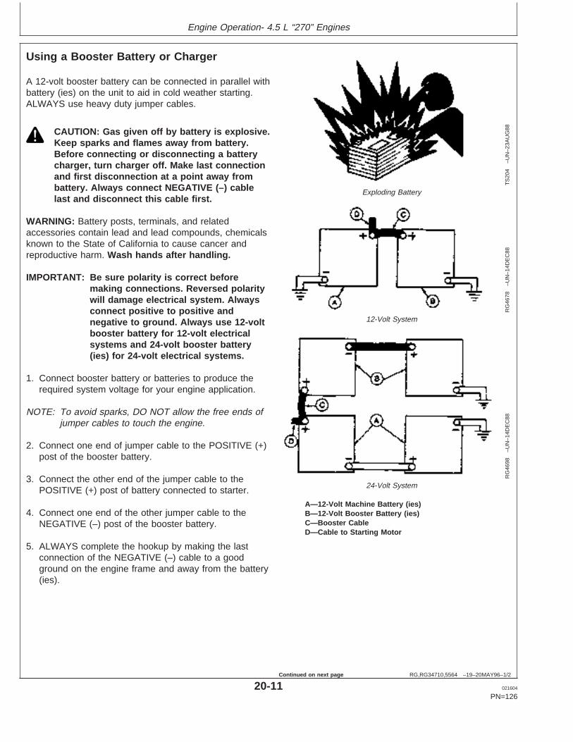
Engine Operation- 4.5 L “270” Engines
RG,RG34710,5564 –19–20MAY96–1/2
Using a Booster Battery or Charger
TS
204
–UN
–23A
UG
88
Exploding Battery
RG
4678
–UN
–14D
EC
88
12-Volt System
RG
4698
–UN
–14D
EC
88
24-Volt System
A—12-Volt Machine Battery (ies)B—12-Volt Booster Battery (ies)C—Booster CableD—Cable to Starting Motor
A 12-volt booster battery can be connected in parallel withbattery (ies) on the unit to aid in cold weather starting.ALWAYS use heavy duty jumper cables.
CAUTION: Gas given off by battery is explosive.Keep sparks and flames away from battery.Before connecting or disconnecting a batterycharger, turn charger off. Make last connectionand first disconnection at a point away frombattery. Always connect NEGATIVE (–) cablelast and disconnect this cable first.
WARNING: Battery posts, terminals, and relatedaccessories contain lead and lead compounds, chemicalsknown to the State of California to cause cancer andreproductive harm. Wash hands after handling.
IMPORTANT: Be sure polarity is correct beforemaking connections. Reversed polaritywill damage electrical system. Alwaysconnect positive to positive andnegative to ground. Always use 12-voltbooster battery for 12-volt electricalsystems and 24-volt booster battery(ies) for 24-volt electrical systems.
1. Connect booster battery or batteries to produce therequired system voltage for your engine application.
NOTE: To avoid sparks, DO NOT allow the free ends ofjumper cables to touch the engine.
2. Connect one end of jumper cable to the POSITIVE (+)post of the booster battery.
3. Connect the other end of the jumper cable to thePOSITIVE (+) post of battery connected to starter.
4. Connect one end of the other jumper cable to theNEGATIVE (–) post of the booster battery.
5. ALWAYS complete the hookup by making the lastconnection of the NEGATIVE (–) cable to a goodground on the engine frame and away from the battery(ies).
20-11 021604
PN=126
Continued on next page
https://www.truck-manuals.net/
Engine Operation- 4.5 L “270” Engines
RG,RG34710,5564 –19–20MAY96–2/2
6. Start the engine. Disconnect jumper cablesimmediately after engine starts. Disconnect NEGATIVE(–) cable first.
20-12 021604
PN=127
https://www.truck-manuals.net/
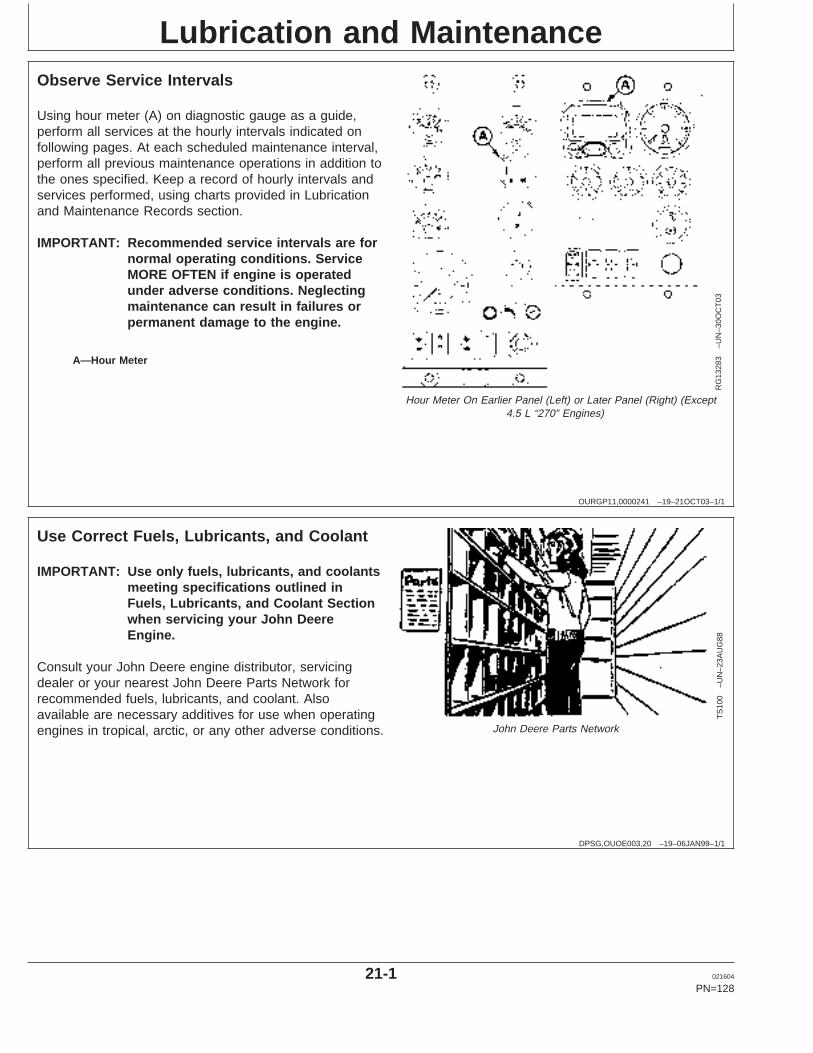
Lubrication and Maintenance
OURGP11,0000241 –19–21OCT03–1/1
Observe Service Intervals
RG
1328
3–U
N–3
0OC
T03
Hour Meter On Earlier Panel (Left) or Later Panel (Right) (Except4.5 L “270” Engines)
A—Hour Meter
Using hour meter (A) on diagnostic gauge as a guide,perform all services at the hourly intervals indicated onfollowing pages. At each scheduled maintenance interval,perform all previous maintenance operations in addition tothe ones specified. Keep a record of hourly intervals andservices performed, using charts provided in Lubricationand Maintenance Records section.
IMPORTANT: Recommended service intervals are fornormal operating conditions. ServiceMORE OFTEN if engine is operatedunder adverse conditions. Neglectingmaintenance can result in failures orpermanent damage to the engine.
DPSG,OUOE003,20 –19–06JAN99–1/1
Use Correct Fuels, Lubricants, and Coolant
TS
100
–UN
–23A
UG
88John Deere Parts Network
IMPORTANT: Use only fuels, lubricants, and coolantsmeeting specifications outlined inFuels, Lubricants, and Coolant Sectionwhen servicing your John DeereEngine.
Consult your John Deere engine distributor, servicingdealer or your nearest John Deere Parts Network forrecommended fuels, lubricants, and coolant. Alsoavailable are necessary additives for use when operatingengines in tropical, arctic, or any other adverse conditions.
21-1 021604
PN=128
https://www.truck-manuals.net/
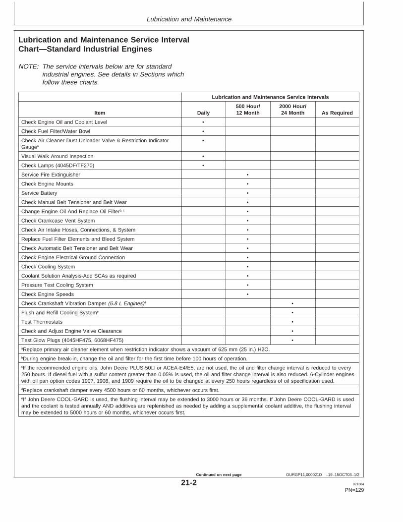
Lubrication and Maintenance
OURGP11,000021D –19–15OCT03–1/2
Lubrication and Maintenance Service IntervalChart—Standard Industrial Engines
NOTE: The service intervals below are for standardindustrial engines. See details in Sections whichfollow these charts.
Lubrication and Maintenance Service Intervals
500 Hour/ 2000 Hour/Item Daily 12 Month 24 Month As Required
Check Engine Oil and Coolant Level •
Check Fuel Filter/Water Bowl •
Check Air Cleaner Dust Unloader Valve & Restriction Indicator •Gaugea
Visual Walk Around Inspection •
Check Lamps (4045DF/TF270) •
Service Fire Extinguisher •
Check Engine Mounts •
Service Battery •
Check Manual Belt Tensioner and Belt Wear •
Change Engine Oil And Replace Oil Filterb, c •
Check Crankcase Vent System •
Check Air Intake Hoses, Connections, & System •
Replace Fuel Filter Elements and Bleed System •
Check Automatic Belt Tensioner and Belt Wear •
Check Engine Electrical Ground Connection •
Check Cooling System •
Coolant Solution Analysis-Add SCAs as required •
Pressure Test Cooling System •
Check Engine Speeds •
Check Crankshaft Vibration Damper (6.8 L Engines)d •
Flush and Refill Cooling Systeme •
Test Thermostats •
Check and Adjust Engine Valve Clearance •
Test Glow Plugs (4045HF475, 6068HF475) •aReplace primary air cleaner element when restriction indicator shows a vacuum of 625 mm (25 in.) H2O.bDuring engine break-in, change the oil and filter for the first time before 100 hours of operation.cIf the recommended engine oils, John Deere PLUS-50 or ACEA-E4/E5, are not used, the oil and filter change interval is reduced to every250 hours. If diesel fuel with a sulfur content greater than 0.05% is used, the oil and filter change interval is also reduced. 6-Cylinder engineswith oil pan option codes 1907, 1908, and 1909 require the oil to be changed at every 250 hours regardless of oil specification used.dReplace crankshaft damper every 4500 hours or 60 months, whichever occurs first.eIf John Deere COOL-GARD is used, the flushing interval may be extended to 3000 hours or 36 months. If John Deere COOL-GARD is usedand the coolant is tested annually AND additives are replenished as needed by adding a supplemental coolant additive, the flushing intervalmay be extended to 5000 hours or 60 months, whichever occurs first.
21-2 021604
PN=129
Continued on next page
https://www.truck-manuals.net/
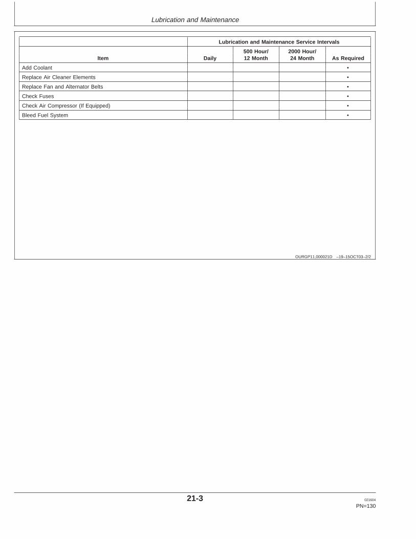
Lubrication and Maintenance
OURGP11,000021D –19–15OCT03–2/2
Lubrication and Maintenance Service Intervals
500 Hour/ 2000 Hour/Item Daily 12 Month 24 Month As Required
Add Coolant •
Replace Air Cleaner Elements •
Replace Fan and Alternator Belts •
Check Fuses •
Check Air Compressor (If Equipped) •
Bleed Fuel System •
21-3 021604
PN=130
https://www.truck-manuals.net/
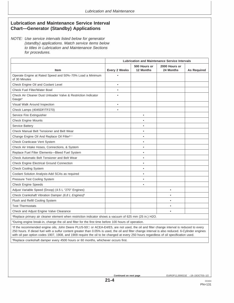
Lubrication and Maintenance
OURGP11,000021E –19–15OCT03–1/2
Lubrication and Maintenance Service IntervalChart—Generator (Standby) Applications
NOTE: Use service intervals listed below for generator(standby) applications. Match service items belowto titles in Lubrication and Maintenance Sectionsfor procedures.
Lubrication and Maintenance Service Intervals
500 Hours or 2000 Hours orItem Every 2 Weeks 12 Months 24 Months As Required
Operate Engine at Rated Speed and 50%–70% Load a Minimum •of 30 Minutes
Check Engine Oil and Coolant Level •
Check Fuel Filter/Water Bowl •
Check Air Cleaner Dust Unloader Valve & Restriction Indicator •Gaugea
Visual Walk Around Inspection •
Check Lamps (4045DF/TF270) •
Service Fire Extinguisher •
Check Engine Mounts •
Service Battery •
Check Manual Belt Tensioner and Belt Wear •
Change Engine Oil And Replace Oil Filterb, c •
Check Crankcase Vent System •
Check Air Intake Hoses, Connections, & System •
Replace Fuel Filter Elements—Bleed Fuel System •
Check Automatic Belt Tensioner and Belt Wear •
Check Engine Electrical Ground Connection •
Check Cooling System •
Coolant Solution Analysis-Add SCAs as required •
Pressure Test Cooling System •
Check Engine Speeds •
Adjust Variable Speed (Droop) (4.5 L “270” Engines) •
Check Crankshaft Vibration Damper (6.8 L Engines)d •
Flush and Refill Cooling System •
Test Thermostats •
Check and Adjust Engine Valve Clearance •aReplace primary air cleaner element when restriction indicator shows a vacuum of 625 mm (25 in.) H2O.bDuring engine break-in, change the oil and filter for the first time before 100 hours of operation.cIf the recommended engine oils, John Deere PLUS-50 or ACEA-E4/E5, are not used, the oil and filter change interval is reduced to every250 hours. If diesel fuel with a sulfur content greater than 0.05% is used, the oil and filter change interval is also reduced. 6-Cylinder engineswith oil pan option codes 1907, 1908, and 1909 require the oil to be changed at every 250 hours regardless of oil specification used.dReplace crankshaft damper every 4500 hours or 60 months, whichever occurs first.
21-4 021604
PN=131
Continued on next page
https://www.truck-manuals.net/
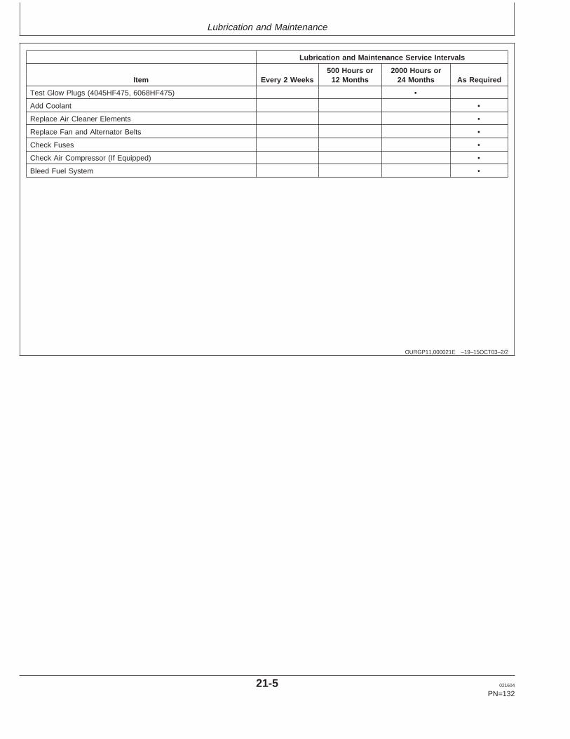
Lubrication and Maintenance
OURGP11,000021E –19–15OCT03–2/2
Lubrication and Maintenance Service Intervals
500 Hours or 2000 Hours orItem Every 2 Weeks 12 Months 24 Months As Required
Test Glow Plugs (4045HF475, 6068HF475) •
Add Coolant •
Replace Air Cleaner Elements •
Replace Fan and Alternator Belts •
Check Fuses •
Check Air Compressor (If Equipped) •
Bleed Fuel System •
21-5 021604
PN=132
https://www.truck-manuals.net/
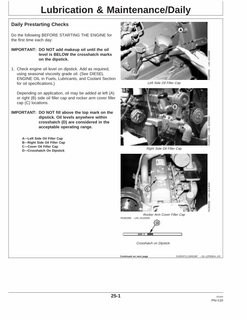
Lubrication & Maintenance/Daily
OURGP11,000018F –19–12FEB04–1/5
Daily Prestarting Checks
RG
8009
A–U
N–1
6JU
N00
Left Side Oil Filler Cap
RG
8054
A–U
N–1
6JU
N00
Right Side Oil Filler Cap
RG
8025
B–U
N–1
6JU
N00
Rocker Arm Cover Filler CapRG8028B –UN–15JAN99
Crosshatch on Dipstick
A—Left Side Oil Filler CapB—Right Side Oil Filler CapC—Cover Oil Filler CapD—Crosshatch On Dipstick
Do the following BEFORE STARTING THE ENGINE forthe first time each day:
IMPORTANT: DO NOT add makeup oil until the oillevel is BELOW the crosshatch markson the dipstick.
1. Check engine oil level on dipstick. Add as required,using seasonal viscosity grade oil. (See DIESELENGINE OIL in Fuels, Lubricants, and Coolant Sectionfor oil specifications.)
Depending on application, oil may be added at left (A)or right (B) side oil filler cap and rocker arm cover fillercap (C) locations.
IMPORTANT: DO NOT fill above the top mark on thedipstick. Oil levels anywhere withincrosshatch (D) are considered in theacceptable operating range.
Continued on next page
25-1 021604
PN=133
https://www.truck-manuals.net/
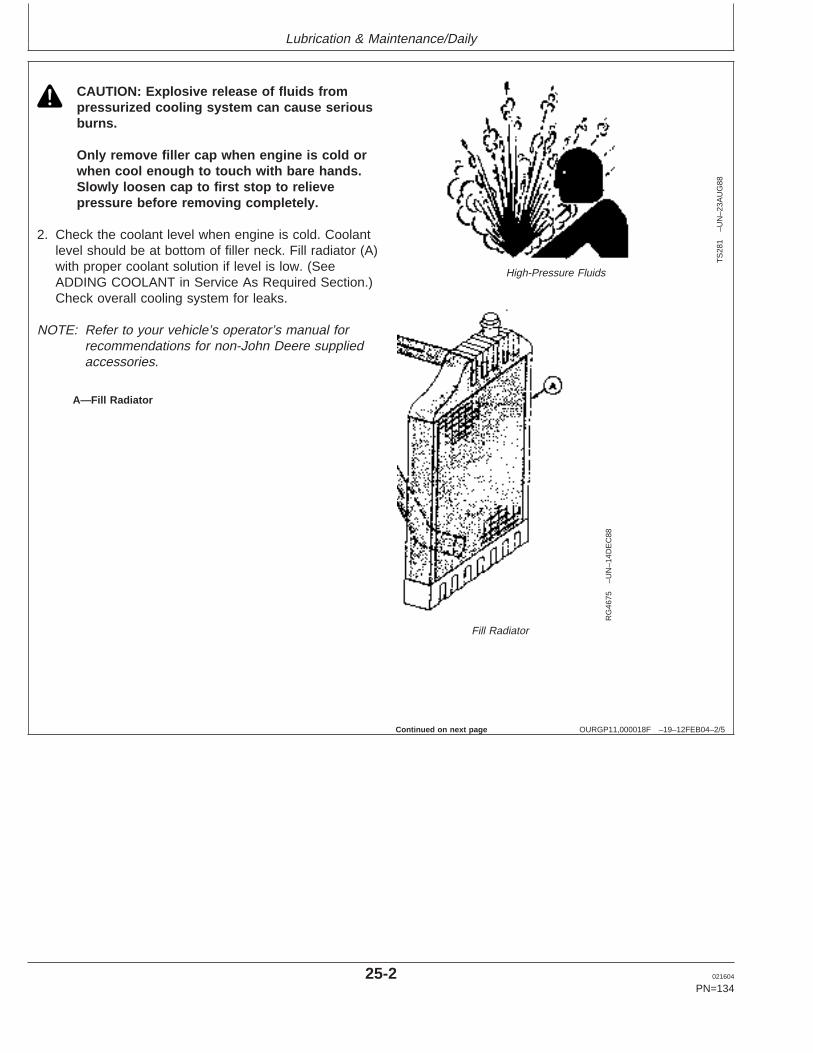
Lubrication & Maintenance/Daily
OURGP11,000018F –19–12FEB04–2/5T
S28
1–U
N–2
3AU
G88
High-Pressure Fluids
RG
4675
–UN
–14D
EC
88
Fill Radiator
A—Fill Radiator
CAUTION: Explosive release of fluids frompressurized cooling system can cause seriousburns.
Only remove filler cap when engine is cold orwhen cool enough to touch with bare hands.Slowly loosen cap to first stop to relievepressure before removing completely.
2. Check the coolant level when engine is cold. Coolantlevel should be at bottom of filler neck. Fill radiator (A)with proper coolant solution if level is low. (SeeADDING COOLANT in Service As Required Section.)Check overall cooling system for leaks.
NOTE: Refer to your vehicle’s operator’s manual forrecommendations for non-John Deere suppliedaccessories.
Continued on next page
25-2 021604
PN=134
https://www.truck-manuals.net/
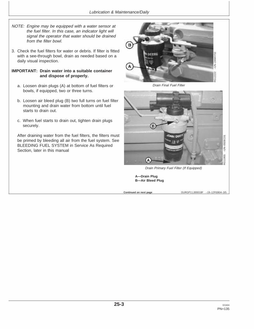
Lubrication & Maintenance/Daily
OURGP11,000018F –19–12FEB04–3/5
RG
1222
2–U
N–2
4MA
Y02
Drain Final Fuel Filter
RG
1195
5–U
N–0
5DE
C01
Drain Primary Fuel Filter (If Equipped)
A—Drain PlugB—Air Bleed Plug
NOTE: Engine may be equipped with a water sensor atthe fuel filter. In this case, an indicator light willsignal the operator that water should be drainedfrom the filter bowl.
3. Check the fuel filters for water or debris. If filter is fittedwith a see-through bowl, drain as needed based on adaily visual inspection.
IMPORTANT: Drain water into a suitable containerand dispose of properly.
a. Loosen drain plugs (A) at bottom of fuel filters orbowls, if equipped, two or three turns.
b. Loosen air bleed plug (B) two full turns on fuel filtermounting and drain water from bottom until fuelstarts to drain out.
c. When fuel starts to drain out, tighten drain plugssecurely.
After draining water from the fuel filters, the filters mustbe primed by bleeding all air from the fuel system. SeeBLEEDING FUEL SYSTEM in Service As RequiredSection, later in this manual
Continued on next page
25-3 021604
PN=135
https://www.truck-manuals.net/
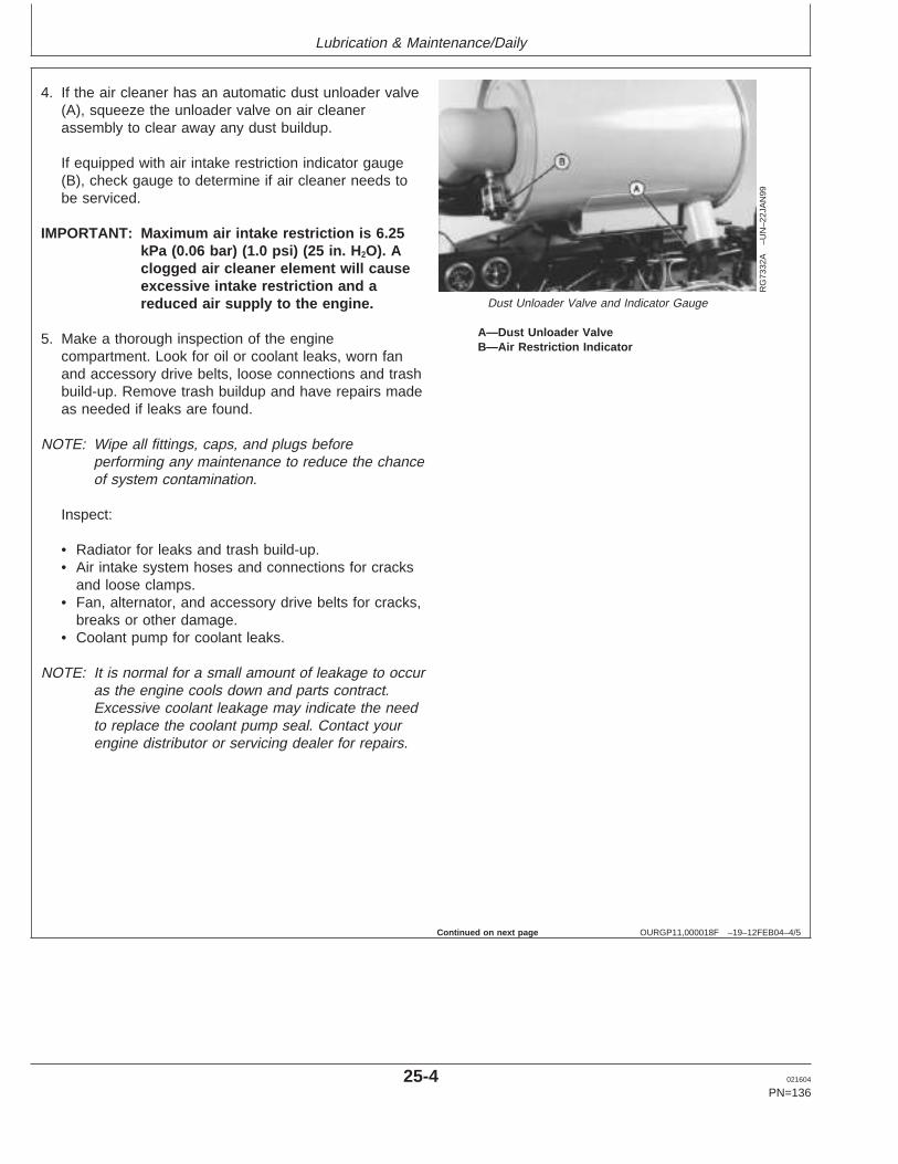
Lubrication & Maintenance/Daily
OURGP11,000018F –19–12FEB04–4/5
RG
7332
A–U
N–2
2JA
N99
Dust Unloader Valve and Indicator Gauge
A—Dust Unloader ValveB—Air Restriction Indicator
4. If the air cleaner has an automatic dust unloader valve(A), squeeze the unloader valve on air cleanerassembly to clear away any dust buildup.
If equipped with air intake restriction indicator gauge(B), check gauge to determine if air cleaner needs tobe serviced.
IMPORTANT: Maximum air intake restriction is 6.25kPa (0.06 bar) (1.0 psi) (25 in. H 2O). Aclogged air cleaner element will causeexcessive intake restriction and areduced air supply to the engine.
5. Make a thorough inspection of the enginecompartment. Look for oil or coolant leaks, worn fanand accessory drive belts, loose connections and trashbuild-up. Remove trash buildup and have repairs madeas needed if leaks are found.
NOTE: Wipe all fittings, caps, and plugs beforeperforming any maintenance to reduce the chanceof system contamination.
Inspect:
• Radiator for leaks and trash build-up.• Air intake system hoses and connections for cracks
and loose clamps.• Fan, alternator, and accessory drive belts for cracks,
breaks or other damage.• Coolant pump for coolant leaks.
NOTE: It is normal for a small amount of leakage to occuras the engine cools down and parts contract.Excessive coolant leakage may indicate the needto replace the coolant pump seal. Contact yourengine distributor or servicing dealer for repairs.
Continued on next page
25-4 021604
PN=136
https://www.truck-manuals.net/
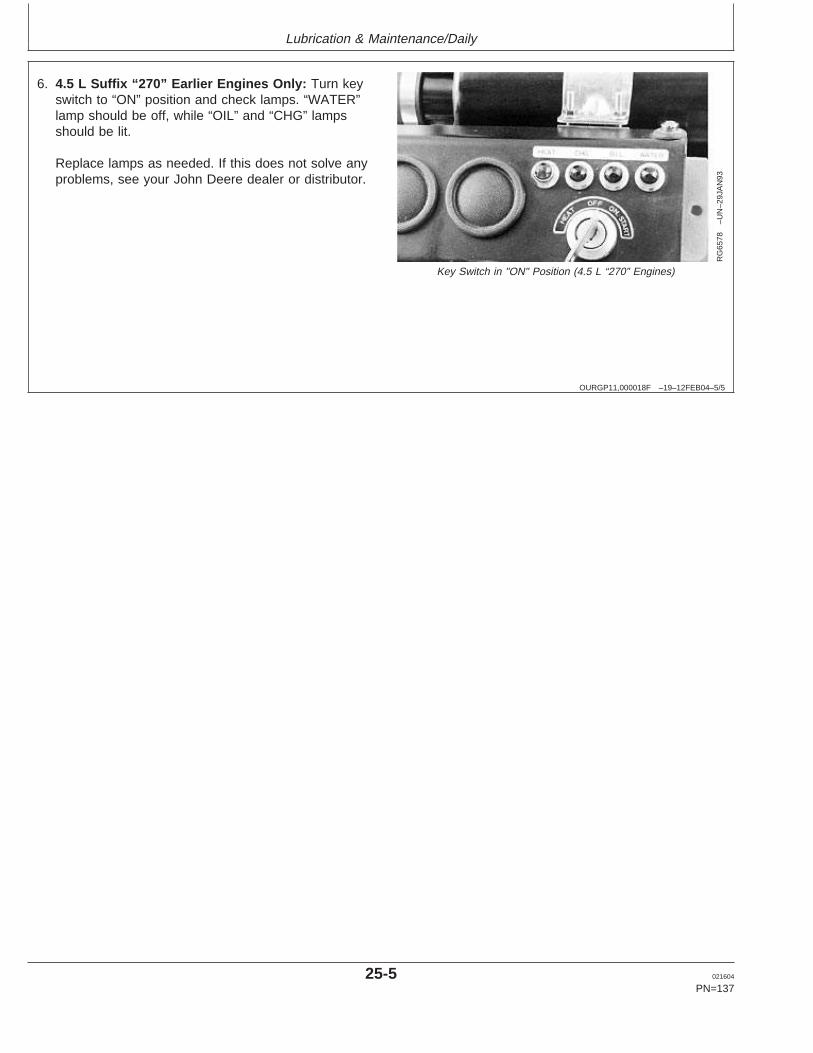
Lubrication & Maintenance/Daily
OURGP11,000018F –19–12FEB04–5/5
RG
6578
–UN
–29J
AN
93
Key Switch in "ON" Position (4.5 L “270” Engines)
6. 4.5 L Suffix “270” Earlier Engines Only: Turn keyswitch to “ON” position and check lamps. “WATER”lamp should be off, while “OIL” and “CHG” lampsshould be lit.
Replace lamps as needed. If this does not solve anyproblems, see your John Deere dealer or distributor.
25-5 021604
PN=137
https://www.truck-manuals.net/

Lubrication & Maintenance/500 Hour/12 Month
OURGP11,000015F –19–28JAN04–1/1
Servicing Fire Extinguisher
RW
4918
–UN
–15D
EC
88
Fire ExtinguisherA—Fire Extinguisher
A fire extinguisher (A) is available from your authorizedservicing dealer or engine distributor.
Read and follow the instructions which are packaged withit. The extinguisher should be inspected at least every 500hours of engine operation or every 6 months. Onceextinguisher is operated, no matter how long, it must berecharged. Keep record of inspections on the tag whichcomes with the extinguisher instruction booklet.
OURGP11,0000110 –19–16OCT03–1/1
Checking Engine Mounts
RG
9905
–UN
–06J
AN
99
Engine Mounting
A—Mounting Bracket
Engine mounting is the responsibility of the vehicle orgenerator manufacturer. Follow manufacturer’s guidelinesfor mounting specifications.
IMPORTANT: Use only Grade SAE 8 or higher gradeof hardware for engine mounting.
1. Check the engine mounting brackets (A), vibrationisolators, and mounting bolts on support frame andengine block for tightness. Tighten as necessary.
2. Inspect overall condition of vibration isolators, ifequipped. Replace isolators, as necessary, if rubberhas deteriorated or mounts have collapsed.
30-1 021604
PN=138
https://www.truck-manuals.net/
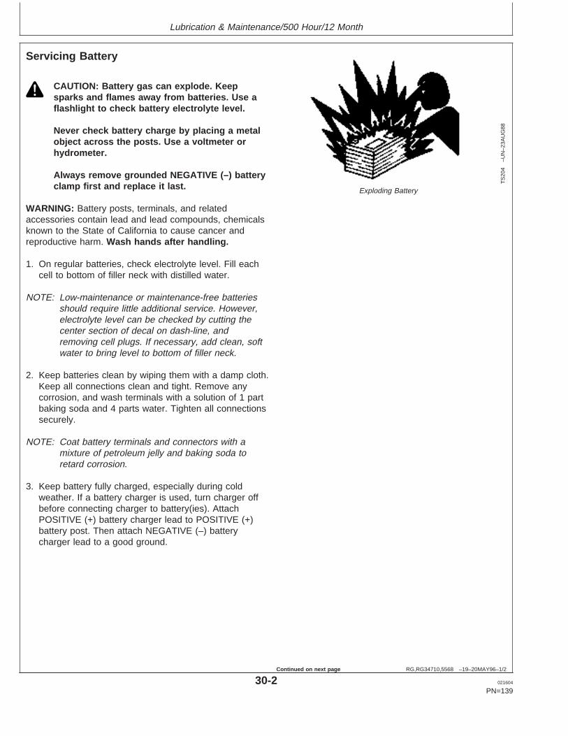
Lubrication & Maintenance/500 Hour/12 Month
RG,RG34710,5568 –19–20MAY96–1/2
Servicing Battery
TS
204
–UN
–23A
UG
88
Exploding Battery
CAUTION: Battery gas can explode. Keepsparks and flames away from batteries. Use aflashlight to check battery electrolyte level.
Never check battery charge by placing a metalobject across the posts. Use a voltmeter orhydrometer.
Always remove grounded NEGATIVE (–) batteryclamp first and replace it last.
WARNING: Battery posts, terminals, and relatedaccessories contain lead and lead compounds, chemicalsknown to the State of California to cause cancer andreproductive harm. Wash hands after handling.
1. On regular batteries, check electrolyte level. Fill eachcell to bottom of filler neck with distilled water.
NOTE: Low-maintenance or maintenance-free batteriesshould require little additional service. However,electrolyte level can be checked by cutting thecenter section of decal on dash-line, andremoving cell plugs. If necessary, add clean, softwater to bring level to bottom of filler neck.
2. Keep batteries clean by wiping them with a damp cloth.Keep all connections clean and tight. Remove anycorrosion, and wash terminals with a solution of 1 partbaking soda and 4 parts water. Tighten all connectionssecurely.
NOTE: Coat battery terminals and connectors with amixture of petroleum jelly and baking soda toretard corrosion.
3. Keep battery fully charged, especially during coldweather. If a battery charger is used, turn charger offbefore connecting charger to battery(ies). AttachPOSITIVE (+) battery charger lead to POSITIVE (+)battery post. Then attach NEGATIVE (–) batterycharger lead to a good ground.
30-2 021604
PN=139
Continued on next page
https://www.truck-manuals.net/
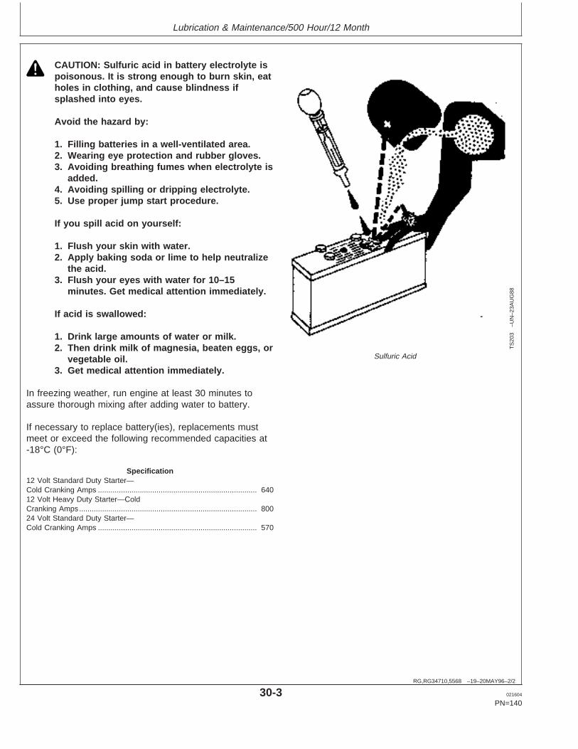
Lubrication & Maintenance/500 Hour/12 Month
RG,RG34710,5568 –19–20MAY96–2/2
TS
203
–UN
–23A
UG
88
Sulfuric Acid
CAUTION: Sulfuric acid in battery electrolyte ispoisonous. It is strong enough to burn skin, eatholes in clothing, and cause blindness ifsplashed into eyes.
Avoid the hazard by:
1. Filling batteries in a well-ventilated area.2. Wearing eye protection and rubber gloves.3. Avoiding breathing fumes when electrolyte is
added.4. Avoiding spilling or dripping electrolyte.5. Use proper jump start procedure.
If you spill acid on yourself:
1. Flush your skin with water.2. Apply baking soda or lime to help neutralize
the acid.3. Flush your eyes with water for 10–15
minutes. Get medical attention immediately.
If acid is swallowed:
1. Drink large amounts of water or milk.2. Then drink milk of magnesia, beaten eggs, or
vegetable oil.3. Get medical attention immediately.
In freezing weather, run engine at least 30 minutes toassure thorough mixing after adding water to battery.
If necessary to replace battery(ies), replacements mustmeet or exceed the following recommended capacities at-18°C (0°F):
Specification12 Volt Standard Duty Starter—Cold Cranking Amps 640............................................................................12 Volt Heavy Duty Starter—ColdCranking Amps 800.....................................................................................24 Volt Standard Duty Starter—Cold Cranking Amps 570............................................................................
30-3 021604
PN=140
https://www.truck-manuals.net/
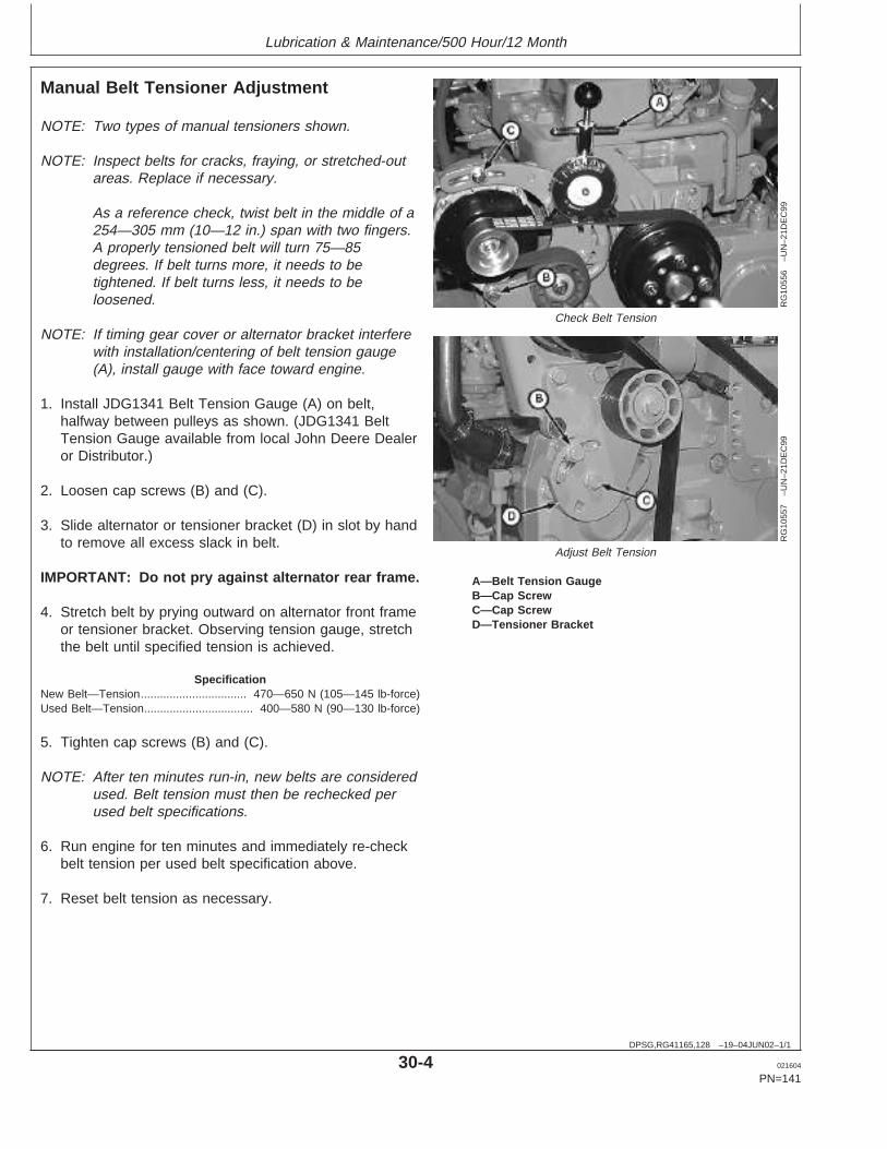
Lubrication & Maintenance/500 Hour/12 Month
DPSG,RG41165,128 –19–04JUN02–1/1
Manual Belt Tensioner Adjustment
RG
1055
6–U
N–2
1DE
C99
Check Belt Tension
RG
1055
7–U
N–2
1DE
C99
Adjust Belt Tension
A—Belt Tension GaugeB—Cap ScrewC—Cap ScrewD—Tensioner Bracket
NOTE: Two types of manual tensioners shown.
NOTE: Inspect belts for cracks, fraying, or stretched-outareas. Replace if necessary.
As a reference check, twist belt in the middle of a254—305 mm (10—12 in.) span with two fingers.A properly tensioned belt will turn 75—85degrees. If belt turns more, it needs to betightened. If belt turns less, it needs to beloosened.
NOTE: If timing gear cover or alternator bracket interferewith installation/centering of belt tension gauge(A), install gauge with face toward engine.
1. Install JDG1341 Belt Tension Gauge (A) on belt,halfway between pulleys as shown. (JDG1341 BeltTension Gauge available from local John Deere Dealeror Distributor.)
2. Loosen cap screws (B) and (C).
3. Slide alternator or tensioner bracket (D) in slot by handto remove all excess slack in belt.
IMPORTANT: Do not pry against alternator rear frame.
4. Stretch belt by prying outward on alternator front frameor tensioner bracket. Observing tension gauge, stretchthe belt until specified tension is achieved.
SpecificationNew Belt—Tension 470—650 N (105—145 lb-force).................................Used Belt—Tension 400—580 N (90—130 lb-force)..................................
5. Tighten cap screws (B) and (C).
NOTE: After ten minutes run-in, new belts are consideredused. Belt tension must then be rechecked perused belt specifications.
6. Run engine for ten minutes and immediately re-checkbelt tension per used belt specification above.
7. Reset belt tension as necessary.
30-4 021604
PN=141
https://www.truck-manuals.net/
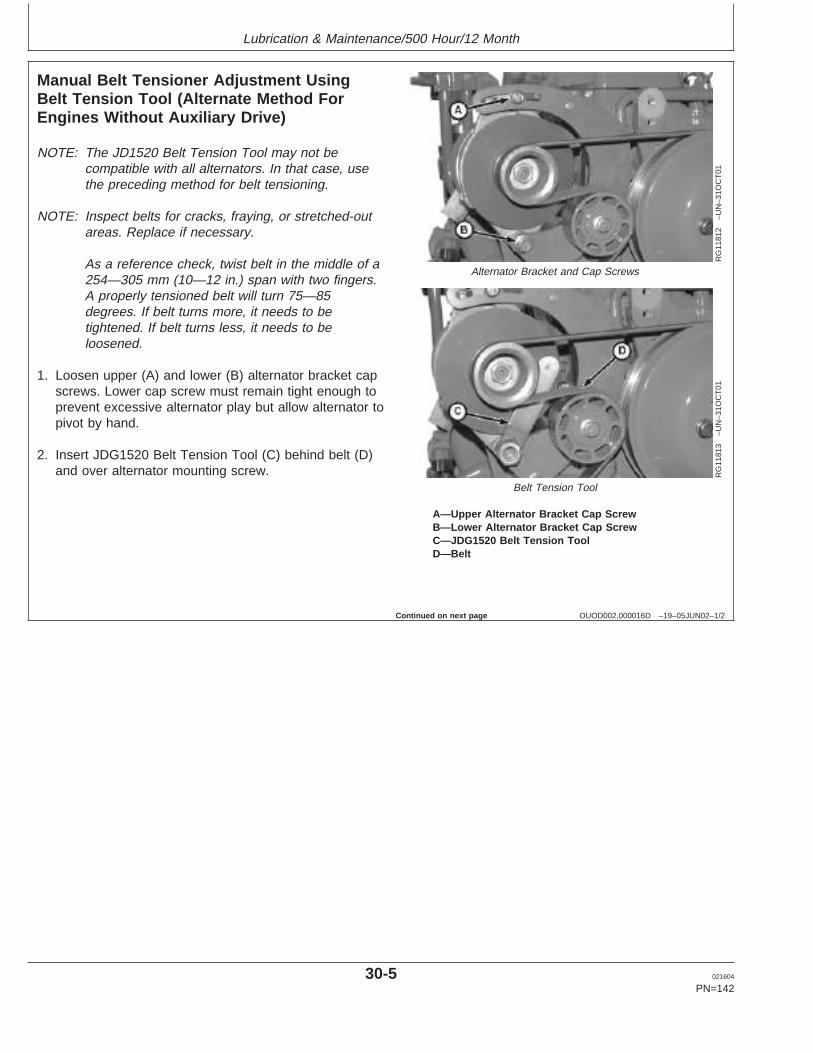
Lubrication & Maintenance/500 Hour/12 Month
OUOD002,000016D –19–05JUN02–1/2
Manual Belt Tensioner Adjustment UsingBelt Tension Tool (Alternate Method ForEngines Without Auxiliary Drive)
RG
1181
2–U
N–3
1OC
T01
Alternator Bracket and Cap Screws
RG
1181
3–U
N–3
1OC
T01
Belt Tension Tool
A—Upper Alternator Bracket Cap ScrewB—Lower Alternator Bracket Cap ScrewC—JDG1520 Belt Tension ToolD—Belt
NOTE: The JD1520 Belt Tension Tool may not becompatible with all alternators. In that case, usethe preceding method for belt tensioning.
NOTE: Inspect belts for cracks, fraying, or stretched-outareas. Replace if necessary.
As a reference check, twist belt in the middle of a254—305 mm (10—12 in.) span with two fingers.A properly tensioned belt will turn 75—85degrees. If belt turns more, it needs to betightened. If belt turns less, it needs to beloosened.
1. Loosen upper (A) and lower (B) alternator bracket capscrews. Lower cap screw must remain tight enough toprevent excessive alternator play but allow alternator topivot by hand.
2. Insert JDG1520 Belt Tension Tool (C) behind belt (D)and over alternator mounting screw.
Continued on next page
30-5 021604
PN=142
https://www.truck-manuals.net/
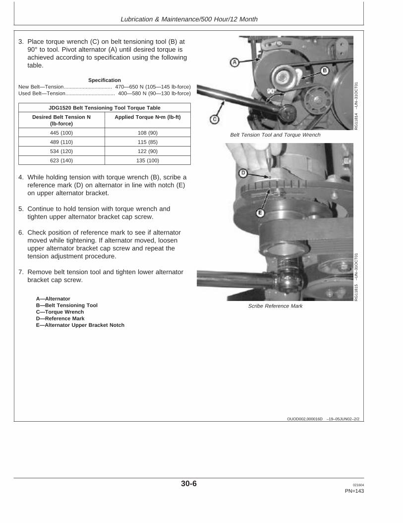
Lubrication & Maintenance/500 Hour/12 Month
OUOD002,000016D –19–05JUN02–2/2
RG
1181
4–U
N–3
1OC
T01
Belt Tension Tool and Torque Wrench
RG
1181
5–U
N–3
1OC
T01
Scribe Reference MarkA—AlternatorB—Belt Tensioning ToolC—Torque WrenchD—Reference MarkE—Alternator Upper Bracket Notch
3. Place torque wrench (C) on belt tensioning tool (B) at90° to tool. Pivot alternator (A) until desired torque isachieved according to specification using the followingtable.
SpecificationNew Belt—Tension 470—650 N (105—145 lb-force).................................Used Belt—Tension 400—580 N (90—130 lb-force)..................................
JDG1520 Belt Tensioning Tool Torque Table
Desired Belt Tension N Applied Torque N •m (lb-ft)(lb-force)
445 (100) 108 (90)
489 (110) 115 (85)
534 (120) 122 (90)
623 (140) 135 (100)
4. While holding tension with torque wrench (B), scribe areference mark (D) on alternator in line with notch (E)on upper alternator bracket.
5. Continue to hold tension with torque wrench andtighten upper alternator bracket cap screw.
6. Check position of reference mark to see if alternatormoved while tightening. If alternator moved, loosenupper alternator bracket cap screw and repeat thetension adjustment procedure.
7. Remove belt tension tool and tighten lower alternatorbracket cap screw.
30-6 021604
PN=143
https://www.truck-manuals.net/
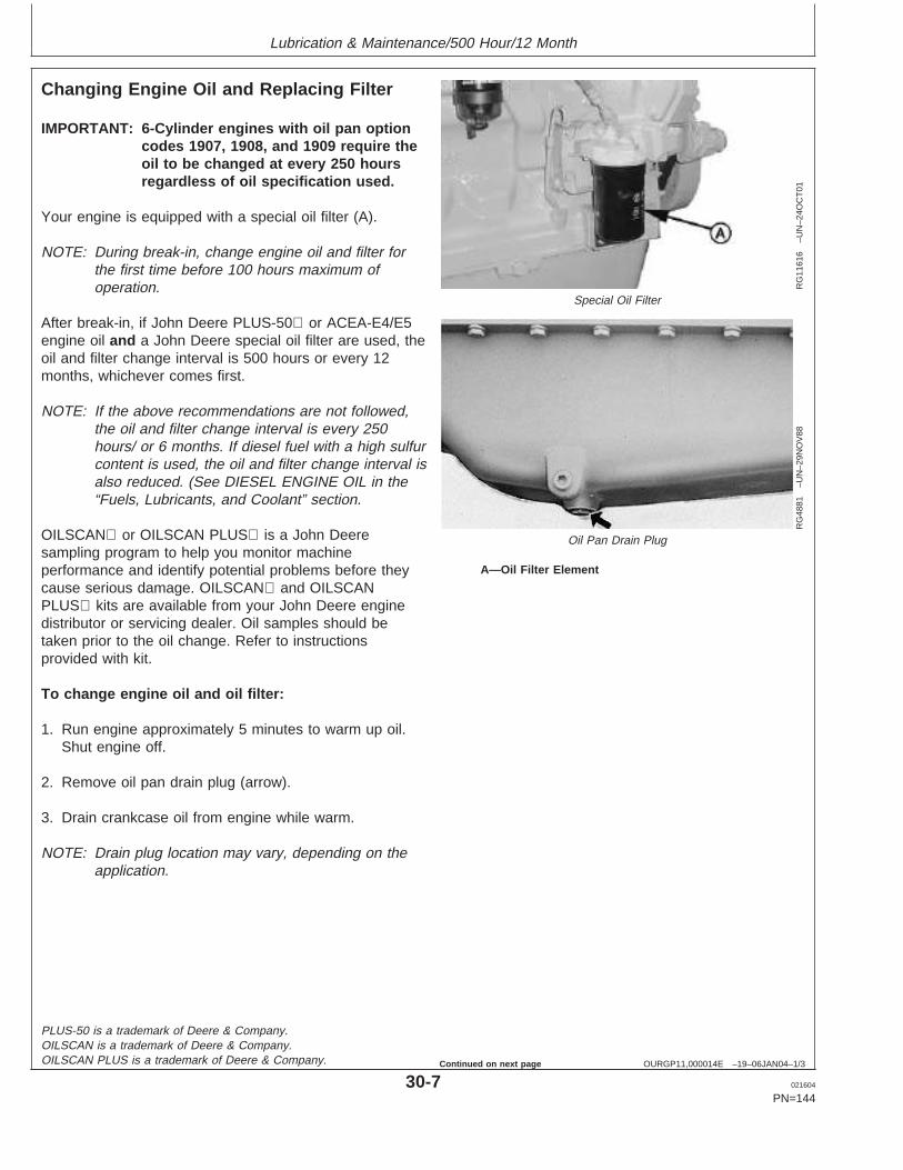
Lubrication & Maintenance/500 Hour/12 Month
OURGP11,000014E –19–06JAN04–1/3
Changing Engine Oil and Replacing Filter
RG
1161
6–U
N–2
4OC
T01
Special Oil Filter
RG
4881
–UN
–29N
OV
88
Oil Pan Drain Plug
A—Oil Filter Element
IMPORTANT: 6-Cylinder engines with oil pan optioncodes 1907, 1908, and 1909 require theoil to be changed at every 250 hoursregardless of oil specification used.
Your engine is equipped with a special oil filter (A).
NOTE: During break-in, change engine oil and filter forthe first time before 100 hours maximum ofoperation.
After break-in, if John Deere PLUS-50 or ACEA-E4/E5engine oil and a John Deere special oil filter are used, theoil and filter change interval is 500 hours or every 12months, whichever comes first.
NOTE: If the above recommendations are not followed,the oil and filter change interval is every 250hours/ or 6 months. If diesel fuel with a high sulfurcontent is used, the oil and filter change interval isalso reduced. (See DIESEL ENGINE OIL in the“Fuels, Lubricants, and Coolant” section.
OILSCAN or OILSCAN PLUS is a John Deeresampling program to help you monitor machineperformance and identify potential problems before theycause serious damage. OILSCAN and OILSCANPLUS kits are available from your John Deere enginedistributor or servicing dealer. Oil samples should betaken prior to the oil change. Refer to instructionsprovided with kit.
To change engine oil and oil filter:
1. Run engine approximately 5 minutes to warm up oil.Shut engine off.
2. Remove oil pan drain plug (arrow).
3. Drain crankcase oil from engine while warm.
NOTE: Drain plug location may vary, depending on theapplication.
PLUS-50 is a trademark of Deere & Company.OILSCAN is a trademark of Deere & Company.OILSCAN PLUS is a trademark of Deere & Company.
30-7 021604
PN=144
Continued on next page
https://www.truck-manuals.net/
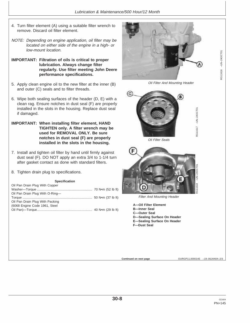
Lubrication & Maintenance/500 Hour/12 Month
OURGP11,000014E –19–06JAN04–2/3
RG
1161
6–U
N–2
4OC
T01
Oil Filter And Mounting Header
RG
1161
7–U
N–2
4OC
T01
Oil Filter Seals
RG
1161
8–U
N–2
4OC
T01
Filter And Mounting Header
A—Oil Filter ElementB—Inner SealC—Outer SealD—Sealing Surface On HeaderE—Sealing Surface On HeaderF—Dust Seal
4. Turn filter element (A) using a suitable filter wrench toremove. Discard oil filter element.
NOTE: Depending on engine application, oil filter may belocated on either side of the engine in a high- orlow-mount location.
IMPORTANT: Filtration of oils is critical to properlubrication. Always change filterregularly. Use filter meeting John Deereperformance specifications.
5. Apply clean engine oil to the new filter at the inner (B)and outer (C) seals and to filter threads.
6. Wipe both sealing surfaces of the header (D, E) with aclean rag. Ensure notches in dust seal (F) are properlyinstalled in the slots in the housing. Replace dust sealif damaged.
IMPORTANT: When installing filter element, HANDTIGHTEN only. A filter wrench may beused for REMOVAL ONLY. Be surenotches in dust seal (F) are properlyinstalled in the slots in the housing.
7. Install and tighten oil filter by hand until firmly againstdust seal (F). DO NOT apply an extra 3/4 to 1-1/4 turnafter gasket contact as done with standard filters.
8. Tighten drain plug to specifications.
SpecificationOil Pan Drain Plug With CopperWasher—Torque 70 N•m (52 lb ft).............................................................Oil Pan Drain Plug With O-Ring—Torque 50 N•m (37 lb ft).............................................................................Oil Pan Drain Plug With Packing(6068 Engine Code 1961, SteelOil Pan)—Torque 40 N•m (29 lb ft).............................................................
Continued on next page
30-8 021604
PN=145
https://www.truck-manuals.net/
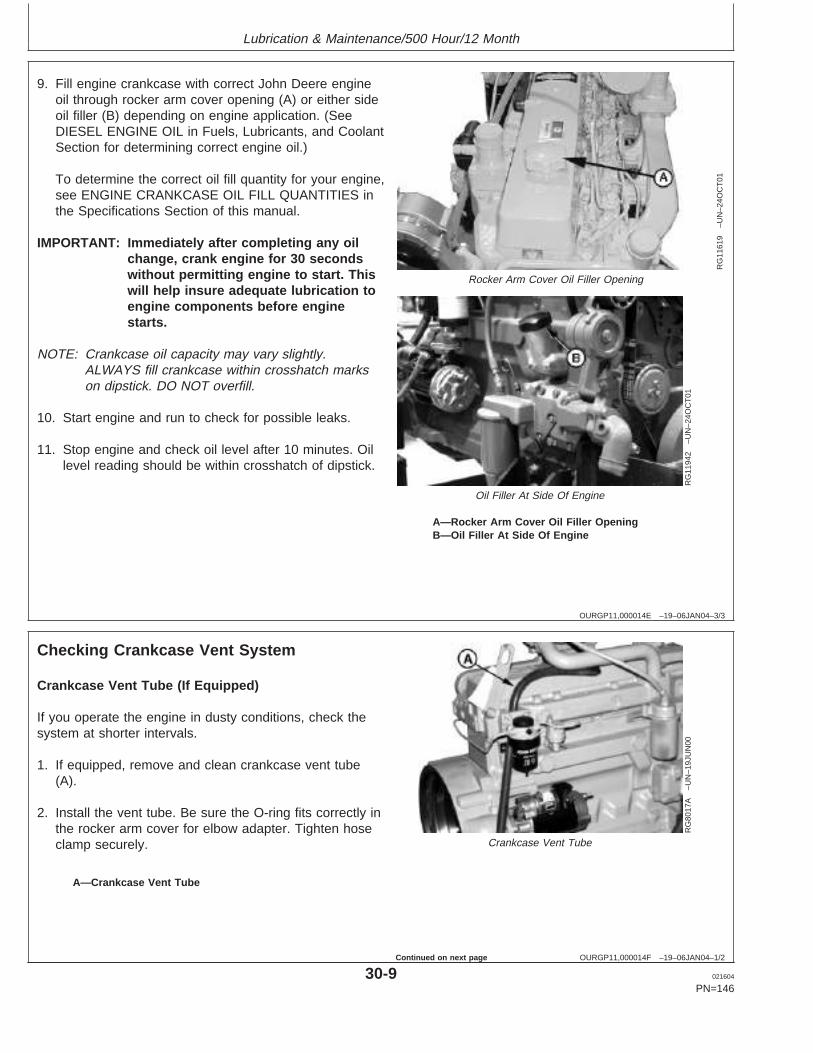
Lubrication & Maintenance/500 Hour/12 Month
OURGP11,000014E –19–06JAN04–3/3
RG
1161
9–U
N–2
4OC
T01
Rocker Arm Cover Oil Filler Opening
RG
1194
2–U
N–2
4OC
T01
Oil Filler At Side Of Engine
A—Rocker Arm Cover Oil Filler OpeningB—Oil Filler At Side Of Engine
9. Fill engine crankcase with correct John Deere engineoil through rocker arm cover opening (A) or either sideoil filler (B) depending on engine application. (SeeDIESEL ENGINE OIL in Fuels, Lubricants, and CoolantSection for determining correct engine oil.)
To determine the correct oil fill quantity for your engine,see ENGINE CRANKCASE OIL FILL QUANTITIES inthe Specifications Section of this manual.
IMPORTANT: Immediately after completing any oilchange, crank engine for 30 secondswithout permitting engine to start. Thiswill help insure adequate lubrication toengine components before enginestarts.
NOTE: Crankcase oil capacity may vary slightly.ALWAYS fill crankcase within crosshatch markson dipstick. DO NOT overfill.
10. Start engine and run to check for possible leaks.
11. Stop engine and check oil level after 10 minutes. Oillevel reading should be within crosshatch of dipstick.
OURGP11,000014F –19–06JAN04–1/2
Checking Crankcase Vent System
RG
8017
A–U
N–1
9JU
N00
Crankcase Vent Tube
A—Crankcase Vent Tube
Crankcase Vent Tube (If Equipped)
If you operate the engine in dusty conditions, check thesystem at shorter intervals.
1. If equipped, remove and clean crankcase vent tube(A).
2. Install the vent tube. Be sure the O-ring fits correctly inthe rocker arm cover for elbow adapter. Tighten hoseclamp securely.
30-9 021604
PN=146
Continued on next page
https://www.truck-manuals.net/
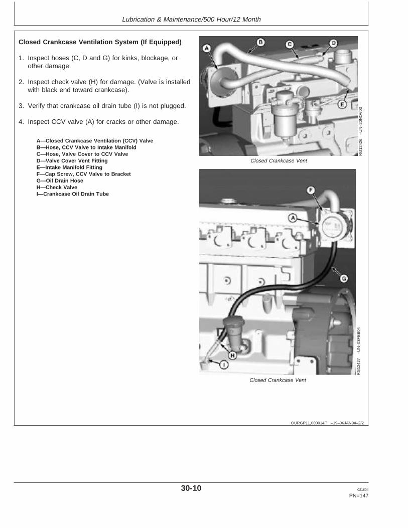
Lubrication & Maintenance/500 Hour/12 Month
OURGP11,000014F –19–06JAN04–2/2
RG
1242
6–U
N–2
0NO
V03
Closed Crankcase Vent
RG
1242
7–U
N–0
3FE
B04
Closed Crankcase Vent
A—Closed Crankcase Ventilation (CCV) ValveB—Hose, CCV Valve to Intake ManifoldC—Hose, Valve Cover to CCV ValveD—Valve Cover Vent FittingE—Intake Manifold FittingF—Cap Screw, CCV Valve to BracketG—Oil Drain HoseH—Check ValveI—Crankcase Oil Drain Tube
Closed Crankcase Ventilation System (If Equipped)
1. Inspect hoses (C, D and G) for kinks, blockage, orother damage.
2. Inspect check valve (H) for damage. (Valve is installedwith black end toward crankcase).
3. Verify that crankcase oil drain tube (I) is not plugged.
4. Inspect CCV valve (A) for cracks or other damage.
30-10 021604
PN=147
https://www.truck-manuals.net/
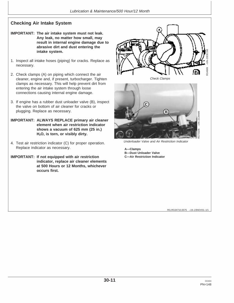
Lubrication & Maintenance/500 Hour/12 Month
RG,RG34710,5575 –19–23NOV01–1/1
Checking Air Intake System
RG
4689
–UN
–20D
EC
88
Check Clamps
RG
7332
B–U
N–2
2JA
N99
Underloader Valve and Air Restriction Indicator
A—ClampsB—Dust Unloader ValveC—Air Restriction Indicator
IMPORTANT: The air intake system must not leak.Any leak, no matter how small, mayresult in internal engine damage due toabrasive dirt and dust entering theintake system.
1. Inspect all intake hoses (piping) for cracks. Replace asnecessary.
2. Check clamps (A) on piping which connect the aircleaner, engine and, if present, turbocharger. Tightenclamps as necessary. This will help prevent dirt fromentering the air intake system through looseconnections causing internal engine damage.
3. If engine has a rubber dust unloader valve (B), inspectthe valve on bottom of air cleaner for cracks orplugging. Replace as necessary.
IMPORTANT: ALWAYS REPLACE primary air cleanerelement when air restriction indicatorshows a vacuum of 625 mm (25 in.)H2O, is torn, or visibly dirty.
4. Test air restriction indicator (C) for proper operation.Replace indicator as necessary.
IMPORTANT: If not equipped with air restrictionindicator, replace air cleaner elementsat 500 Hours or 12 Months, whicheveroccurs first.
30-11 021604
PN=148
https://www.truck-manuals.net/
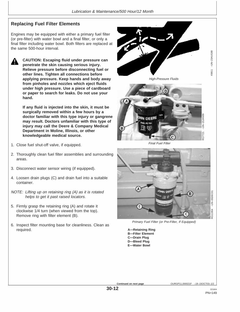
Lubrication & Maintenance/500 Hour/12 Month
OURGP11,000021F –19–15OCT03–1/2
Replacing Fuel Filter Elements
X98
11–U
N–2
3AU
G88
High-Pressure Fluids
RG
7721
–UN
–15J
AN
99
Final Fuel Filter
RG
1195
4–U
N–0
5DE
C01
Primary Fuel Filter (or Pre-Filter, If Equipped)
A—Retaining RingB—Filter ElementC—Drain PlugD—Bleed PlugE—Water Bowl
Engines may be equipped with either a primary fuel filter(or pre-filter) with water bowl and a final filter, or only afinal filter including water bowl. Both filters are replaced atthe same 500-hour interval.
CAUTION: Escaping fluid under pressure canpenetrate the skin causing serious injury.Relieve pressure before disconnecting fuel orother lines. Tighten all connections beforeapplying pressure. Keep hands and body awayfrom pinholes and nozzles which eject fluidsunder high pressure. Use a piece of cardboardor paper to search for leaks. Do not use yourhand.
If any fluid is injected into the skin, it must besurgically removed within a few hours by adoctor familiar with this type injury or gangrenemay result. Doctors unfamiliar with this type ofinjury may call the Deere & Company MedicalDepartment in Moline, Illinois, or otherknowledgeable medical source.
1. Close fuel shut-off valve, if equipped.
2. Thoroughly clean fuel filter assemblies and surroundingareas.
3. Disconnect water sensor wiring (if equipped).
4. Loosen drain plugs (C) and drain fuel into a suitablecontainer.
NOTE: Lifting up on retaining ring (A) as it is rotatedhelps to get it past raised locators.
5. Firmly grasp the retaining ring (A) and rotate itclockwise 1/4 turn (when viewed from the top).Remove ring with filter element (B).
6. Inspect filter mounting base for cleanliness. Clean asrequired.
30-12 021604
PN=149
Continued on next page
https://www.truck-manuals.net/
Lubrication & Maintenance/500 Hour/12 Month
OURGP11,000021F –19–15OCT03–2/2
NOTE: Raised locators on fuel filter canisters must beindexed properly with slots in mounting base forcorrect installation.
7. Install new filter elements onto mounting bases. Besure elements are properly indexed and firmly seatedon bases. It may be necessary to rotate filters forcorrect alignment.
If equipped with water separator bowl (E), remove filterelement from separator bowl. Drain and cleanseparator bowl. Dry with compressed air. Install bowlonto new element. Tighten securely.
8. Align keys on filter element with slots in filter base.
9. Install retaining ring onto mounting base making certaindust seal is in place on filter base. Hand tighten ringcounterclockwise (about 1/3 turn) until it “snaps” intothe detent. DO NOT overtighten retaining ring.
NOTE: The proper installation is indicated when a "click"is heard and a release of the retaining ring is felt.
A plug is provided with the new element forplugging the used element.
10. Reconnect water sensor wiring (if equipped).
11. Open fuel shut-off valve and bleed the fuel system.(See BLEEDING FUEL SYSTEM in Service AsRequired Section.) Tighten bleed plug (D).
30-13 021604
PN=150
https://www.truck-manuals.net/
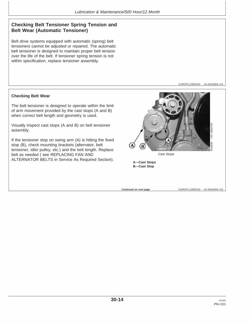
Lubrication & Maintenance/500 Hour/12 Month
OURGP11,0000150 –19–06JAN04–1/3
Checking Belt Tensioner Spring Tension andBelt Wear (Automatic Tensioner)
Belt drive systems equipped with automatic (spring) belttensioners cannot be adjusted or repaired. The automaticbelt tensioner is designed to maintain proper belt tensionover the life of the belt. If tensioner spring tension is notwithin specification, replace tensioner assembly.
OURGP11,0000150 –19–06JAN04–2/3
RG
8098
–UN
–18N
OV
97
Cast Stops
A—Cast StopsB—Cast Stop
Checking Belt Wear
The belt tensioner is designed to operate within the limitof arm movement provided by the cast stops (A and B)when correct belt length and geometry is used.
Visually inspect cast stops (A and B) on belt tensionerassembly.
If the tensioner stop on swing arm (A) is hitting the fixedstop (B), check mounting brackets (alternator, belttensioner, idler pulley, etc.) and the belt length. Replacebelt as needed ( see REPLACING FAN ANDALTERNATOR BELTS in Service As Required Section).
Continued on next page
30-14 021604
PN=151
https://www.truck-manuals.net/
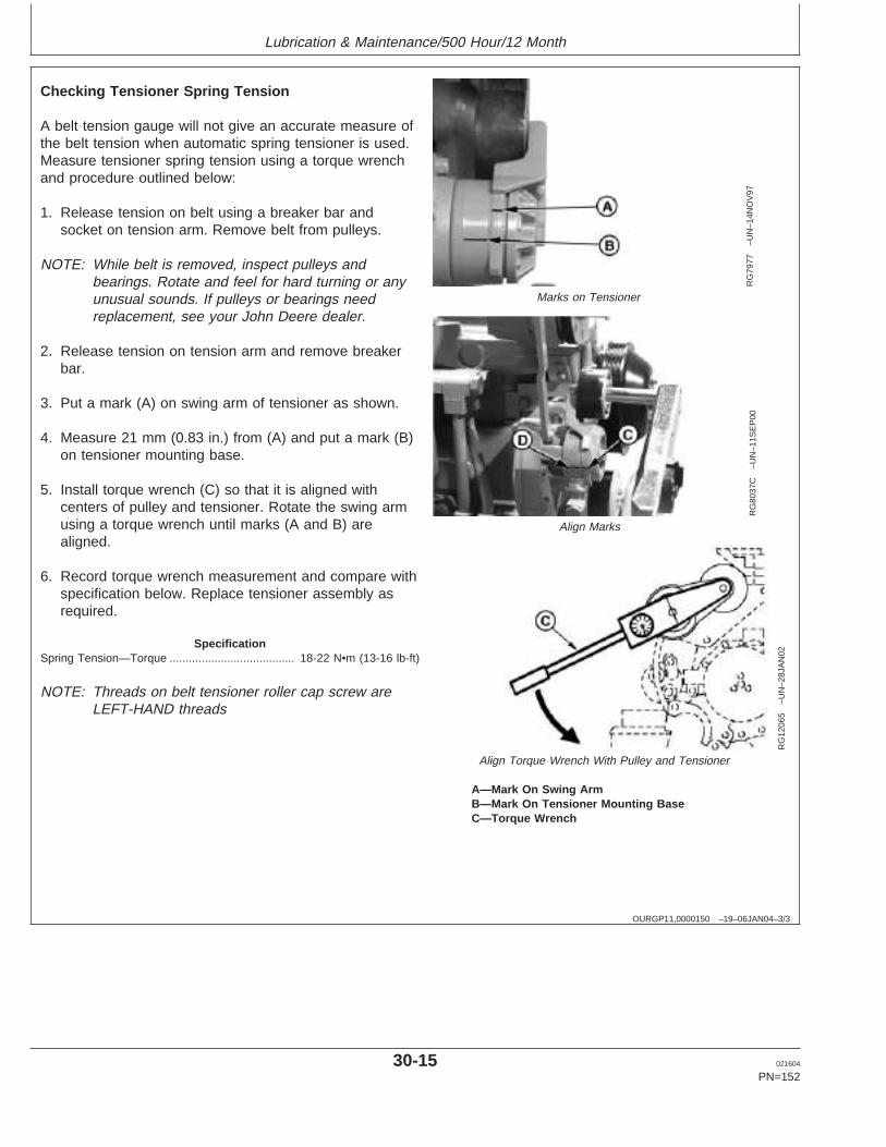
Lubrication & Maintenance/500 Hour/12 Month
OURGP11,0000150 –19–06JAN04–3/3
RG
7977
–UN
–14N
OV
97
Marks on Tensioner
RG
8037
C–U
N–1
1SE
P00
Align Marks
RG
1206
5–U
N–2
8JA
N02
Align Torque Wrench With Pulley and Tensioner
A—Mark On Swing ArmB—Mark On Tensioner Mounting BaseC—Torque Wrench
Checking Tensioner Spring Tension
A belt tension gauge will not give an accurate measure ofthe belt tension when automatic spring tensioner is used.Measure tensioner spring tension using a torque wrenchand procedure outlined below:
1. Release tension on belt using a breaker bar andsocket on tension arm. Remove belt from pulleys.
NOTE: While belt is removed, inspect pulleys andbearings. Rotate and feel for hard turning or anyunusual sounds. If pulleys or bearings needreplacement, see your John Deere dealer.
2. Release tension on tension arm and remove breakerbar.
3. Put a mark (A) on swing arm of tensioner as shown.
4. Measure 21 mm (0.83 in.) from (A) and put a mark (B)on tensioner mounting base.
5. Install torque wrench (C) so that it is aligned withcenters of pulley and tensioner. Rotate the swing armusing a torque wrench until marks (A and B) arealigned.
6. Record torque wrench measurement and compare withspecification below. Replace tensioner assembly asrequired.
SpecificationSpring Tension—Torque 18-22 N•m (13-16 lb-ft).......................................
NOTE: Threads on belt tensioner roller cap screw areLEFT-HAND threads
30-15 021604
PN=152
https://www.truck-manuals.net/
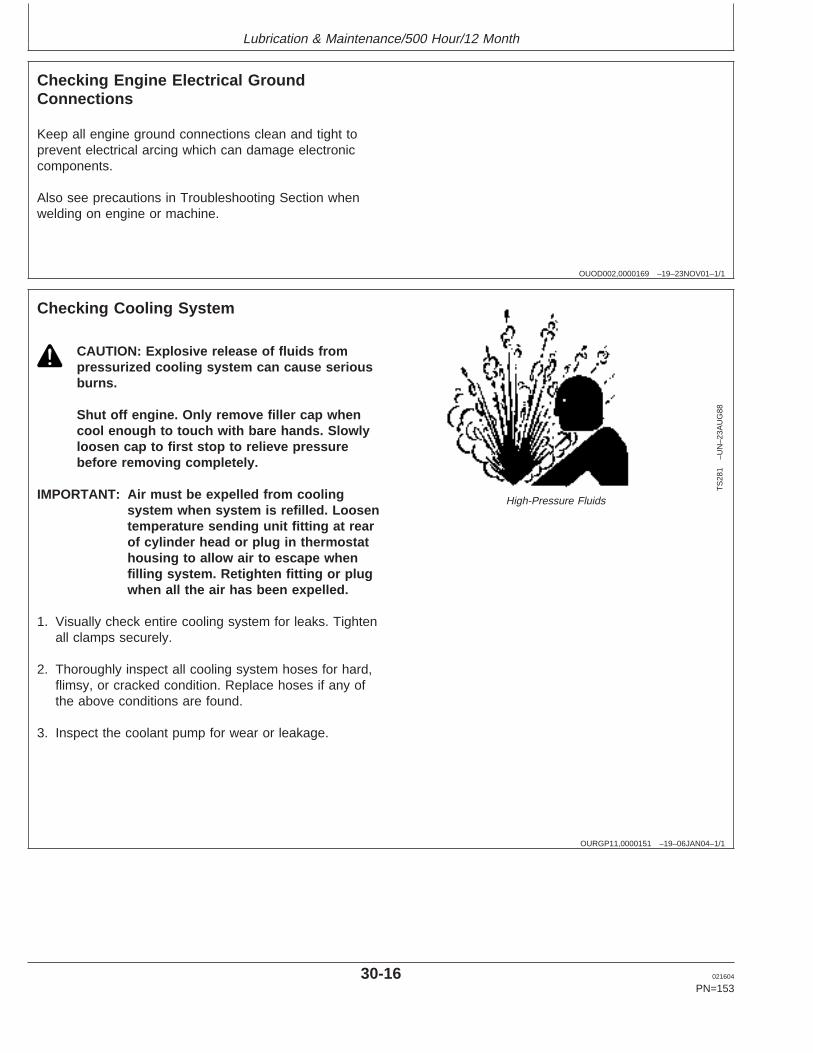
Lubrication & Maintenance/500 Hour/12 Month
OUOD002,0000169 –19–23NOV01–1/1
Checking Engine Electrical GroundConnections
Keep all engine ground connections clean and tight toprevent electrical arcing which can damage electroniccomponents.
Also see precautions in Troubleshooting Section whenwelding on engine or machine.
OURGP11,0000151 –19–06JAN04–1/1
Checking Cooling System
TS
281
–UN
–23A
UG
88
High-Pressure Fluids
CAUTION: Explosive release of fluids frompressurized cooling system can cause seriousburns.
Shut off engine. Only remove filler cap whencool enough to touch with bare hands. Slowlyloosen cap to first stop to relieve pressurebefore removing completely.
IMPORTANT: Air must be expelled from coolingsystem when system is refilled. Loosentemperature sending unit fitting at rearof cylinder head or plug in thermostathousing to allow air to escape whenfilling system. Retighten fitting or plugwhen all the air has been expelled.
1. Visually check entire cooling system for leaks. Tightenall clamps securely.
2. Thoroughly inspect all cooling system hoses for hard,flimsy, or cracked condition. Replace hoses if any ofthe above conditions are found.
3. Inspect the coolant pump for wear or leakage.
30-16 021604
PN=153
https://www.truck-manuals.net/
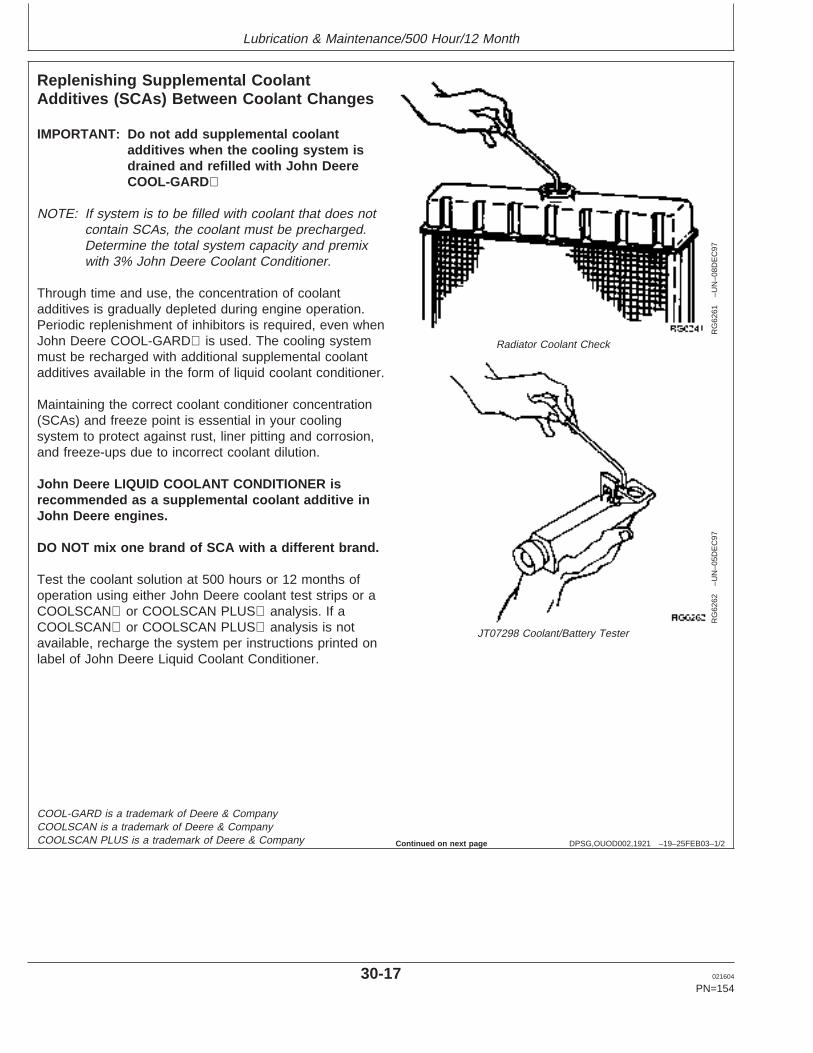
Lubrication & Maintenance/500 Hour/12 Month
DPSG,OUOD002,1921 –19–25FEB03–1/2
Replenishing Supplemental CoolantAdditives (SCAs) Between Coolant Changes
RG
6261
–UN
–08D
EC
97
Radiator Coolant Check
RG
6262
–UN
–05D
EC
97
JT07298 Coolant/Battery Tester
IMPORTANT: Do not add supplemental coolantadditives when the cooling system isdrained and refilled with John DeereCOOL-GARD
NOTE: If system is to be filled with coolant that does notcontain SCAs, the coolant must be precharged.Determine the total system capacity and premixwith 3% John Deere Coolant Conditioner.
Through time and use, the concentration of coolantadditives is gradually depleted during engine operation.Periodic replenishment of inhibitors is required, even whenJohn Deere COOL-GARD is used. The cooling systemmust be recharged with additional supplemental coolantadditives available in the form of liquid coolant conditioner.
Maintaining the correct coolant conditioner concentration(SCAs) and freeze point is essential in your coolingsystem to protect against rust, liner pitting and corrosion,and freeze-ups due to incorrect coolant dilution.
John Deere LIQUID COOLANT CONDITIONER isrecommended as a supplemental coolant additive inJohn Deere engines.
DO NOT mix one brand of SCA with a different brand.
Test the coolant solution at 500 hours or 12 months ofoperation using either John Deere coolant test strips or aCOOLSCAN or COOLSCAN PLUS analysis. If aCOOLSCAN or COOLSCAN PLUS analysis is notavailable, recharge the system per instructions printed onlabel of John Deere Liquid Coolant Conditioner.
COOL-GARD is a trademark of Deere & CompanyCOOLSCAN is a trademark of Deere & CompanyCOOLSCAN PLUS is a trademark of Deere & Company Continued on next page
30-17 021604
PN=154
https://www.truck-manuals.net/
Lubrication & Maintenance/500 Hour/12 Month
DPSG,OUOD002,1921 –19–25FEB03–2/2
IMPORTANT: ALWAYS maintain coolant at correctlevel and concentration. DO NOToperate engine without coolant even fora few minutes.
If frequent coolant makeup is required,the glycol concentration should bechecked with JT07298 Coolant/BatteryTester to ensure that the desired freezepoint is maintained. Followmanufacturer’s instructions providedwith Coolant/Battery Tester.
Add the manufacturer’s recommended concentration ofsupplemental coolant additive. DO NOT add more thanthe recommended amount.
The use of non-recommended supplemental coolantadditives may result in additive drop-out and gelation ofthe coolant.
If other coolants are used, consult the coolant supplierand follow the manufacturer’s recommendation for use ofsupplemental coolant additives.
See DIESEL ENGINE COOLANTS ANDSUPPLEMENTAL ADDITIVE INFORMATION for propermixing of coolant ingredients before adding to the coolingsystem.
30-18 021604
PN=155
https://www.truck-manuals.net/
Lubrication & Maintenance/500 Hour/12 Month
OUOD002,0000175 –19–23NOV01–1/1
Testing Diesel Engine Coolant
Maintaining adequate concentrations of glycol andinhibiting additives in the coolant is critical to protectthe engine and cooling system against freezing,corrosion, and cylinder liner erosion and pitting.
Test the coolant solution at intervals of 12 months orless and whenever excessive coolant is lost throughleaks or overheating.
Coolant Test Strips
Coolant test strips are available from your John Deeredealer. These test strips provide a simple, effectivemethod to check the freeze point and additive levels ofyour engine coolant.
Compare the results to the supplemental coolantadditive (SCA) chart to determine the amount ofinhibiting additives in your coolant and whether moreJohn Deere COOLANT CONDITIONER should beadded.
COOLSCAN Or COOLSCAN PLUS
For a more thorough evaluation of your coolant,perform a COOLSCAN or COOLSCAN PLUS analysis.See your John Deere dealer for information aboutCOOLSCAN or COOLSCAN PLUS.
30-19 021604
PN=156
https://www.truck-manuals.net/
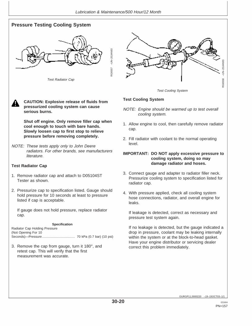
Lubrication & Maintenance/500 Hour/12 Month
OURGP11,0000220 –19–15OCT03–1/1
Pressure Testing Cooling System
RG
6557
–UN
–20J
AN
93
Test Radiator Cap
RG
6558
–UN
–20J
AN
93
Test Cooling System
CAUTION: Explosive release of fluids frompressurized cooling system can causeserious burns.
Shut off engine. Only remove filler cap whencool enough to touch with bare hands.Slowly loosen cap to first stop to relievepressure before removing completely.
NOTE: These tests apply only to John Deereradiators. For other brands, see manufacturersliterature.
Test Radiator Cap
1. Remove radiator cap and attach to D05104STTester as shown.
2. Pressurize cap to specification listed. Gauge shouldhold pressure for 10 seconds at least to pressurelisted if cap is acceptable.
If gauge does not hold pressure, replace radiatorcap.
SpecificationRadiator Cap Holding Pressure(Not Opening For 10Seconds)—Pressure 70 kPa (0.7 bar) (10 psi)....................................
3. Remove the cap from gauge, turn it 180°, andretest cap. This will verify that the firstmeasurement was accurate.
Test Cooling System
NOTE: Engine should be warmed up to test overallcooling system.
1. Allow engine to cool, then carefully remove radiatorcap.
2. Fill radiator with coolant to the normal operatinglevel.
IMPORTANT: DO NOT apply excessive pressure tocooling system, doing so maydamage radiator and hoses.
3. Connect gauge and adapter to radiator filler neck.Pressurize cooling system to specification listed forradiator cap.
4. With pressure applied, check all cooling systemhose connections, radiator, and overall engine forleaks.
If leakage is detected, correct as necessary andpressure test system again.
If no leakage is detected, but the gauge indicated adrop in pressure, coolant may be leaking internallywithin the system or at the block-to-head gasket.Have your engine distributor or servicing dealercorrect this problem immediately.
30-20 021604
PN=157
https://www.truck-manuals.net/
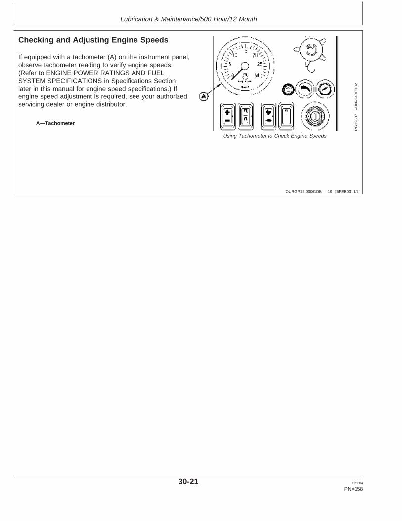
Lubrication & Maintenance/500 Hour/12 Month
OURGP12,00001DB –19–25FEB03–1/1
Checking and Adjusting Engine Speeds
RG
1260
7–U
N–2
4OC
T02
Using Tachometer to Check Engine Speeds
A—Tachometer
If equipped with a tachometer (A) on the instrument panel,observe tachometer reading to verify engine speeds.(Refer to ENGINE POWER RATINGS AND FUELSYSTEM SPECIFICATIONS in Specifications Sectionlater in this manual for engine speed specifications.) Ifengine speed adjustment is required, see your authorizedservicing dealer or engine distributor.
30-21 021604
PN=158
https://www.truck-manuals.net/
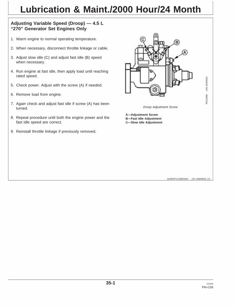
Lubrication & Maint./2000 Hour/24 Month
OURGP12,00001ED –19–14MAR03–1/1
Adjusting Variable Speed (Droop) — 4.5 L“270” Generator Set Engines Only
RG
1206
6–U
N–2
9JA
N02
Droop Adjustment Screw
A—Adjustment ScrewB—Fast Idle AdjustmentC—Slow Idle Adjustment
1. Warm engine to normal operating temperature.
2. When necessary, disconnect throttle linkage or cable.
3. Adjust slow idle (C) and adjust fast idle (B) speedwhen necessary.
4. Run engine at fast idle, then apply load until reachingrated speed.
5. Check power. Adjust with the screw (A) if needed.
6. Remove load from engine.
7. Again check and adjust fast idle if screw (A) has beenturned.
8. Repeat procedure until both the engine power and thefast idle speed are correct.
9. Reinstall throttle linkage if previously removed.
35-1 021604
PN=159
https://www.truck-manuals.net/
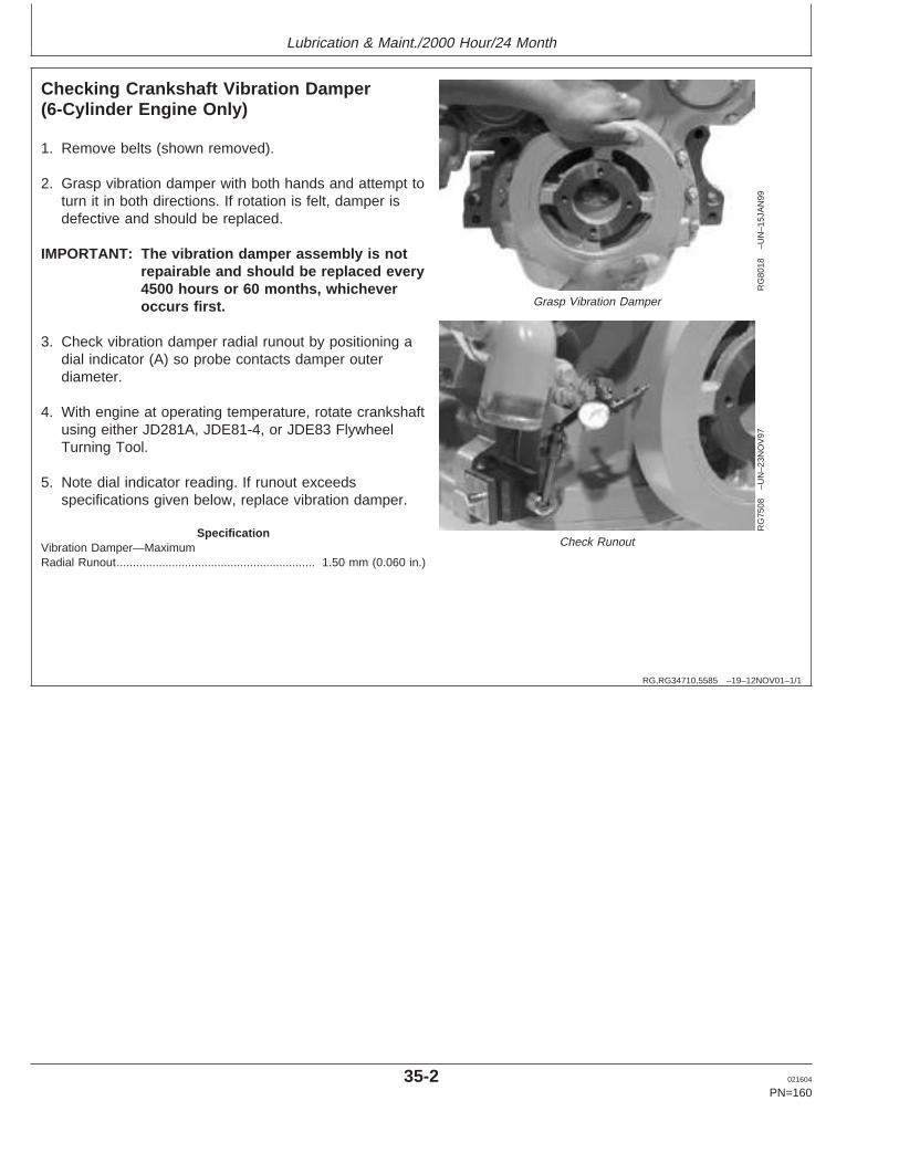
Lubrication & Maint./2000 Hour/24 Month
RG,RG34710,5585 –19–12NOV01–1/1
Checking Crankshaft Vibration Damper(6-Cylinder Engine Only)
RG
8018
–UN
–15J
AN
99
Grasp Vibration Damper
RG
7508
–UN
–23N
OV
97
Check Runout
1. Remove belts (shown removed).
2. Grasp vibration damper with both hands and attempt toturn it in both directions. If rotation is felt, damper isdefective and should be replaced.
IMPORTANT: The vibration damper assembly is notrepairable and should be replaced every4500 hours or 60 months, whicheveroccurs first.
3. Check vibration damper radial runout by positioning adial indicator (A) so probe contacts damper outerdiameter.
4. With engine at operating temperature, rotate crankshaftusing either JD281A, JDE81-4, or JDE83 FlywheelTurning Tool.
5. Note dial indicator reading. If runout exceedsspecifications given below, replace vibration damper.
SpecificationVibration Damper—MaximumRadial Runout 1.50 mm (0.060 in.).............................................................
35-2 021604
PN=160
https://www.truck-manuals.net/
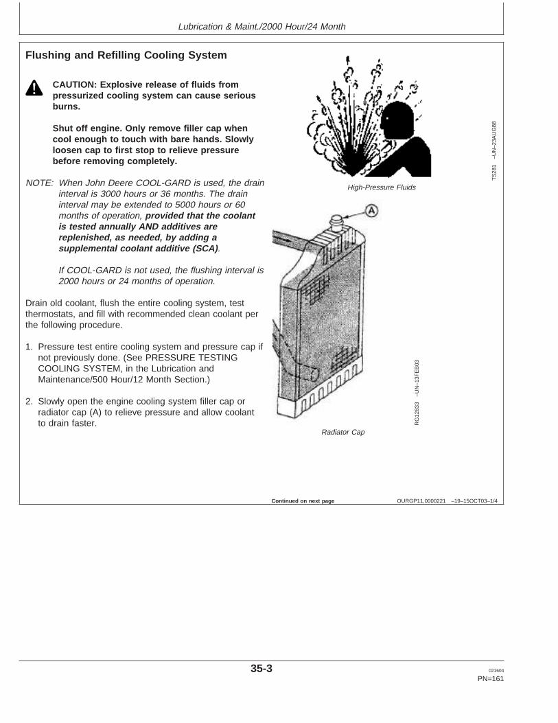
Lubrication & Maint./2000 Hour/24 Month
OURGP11,0000221 –19–15OCT03–1/4
Flushing and Refilling Cooling System
TS
281
–UN
–23A
UG
88
High-Pressure Fluids
RG
1283
3–U
N–1
3FE
B03
Radiator Cap
CAUTION: Explosive release of fluids frompressurized cooling system can cause seriousburns.
Shut off engine. Only remove filler cap whencool enough to touch with bare hands. Slowlyloosen cap to first stop to relieve pressurebefore removing completely.
NOTE: When John Deere COOL-GARD is used, the draininterval is 3000 hours or 36 months. The draininterval may be extended to 5000 hours or 60months of operation, provided that the coolantis tested annually AND additives arereplenished, as needed, by adding asupplemental coolant additive (SCA) .
If COOL-GARD is not used, the flushing interval is2000 hours or 24 months of operation.
Drain old coolant, flush the entire cooling system, testthermostats, and fill with recommended clean coolant perthe following procedure.
1. Pressure test entire cooling system and pressure cap ifnot previously done. (See PRESSURE TESTINGCOOLING SYSTEM, in the Lubrication andMaintenance/500 Hour/12 Month Section.)
2. Slowly open the engine cooling system filler cap orradiator cap (A) to relieve pressure and allow coolantto drain faster.
Continued on next page
35-3 021604
PN=161
https://www.truck-manuals.net/
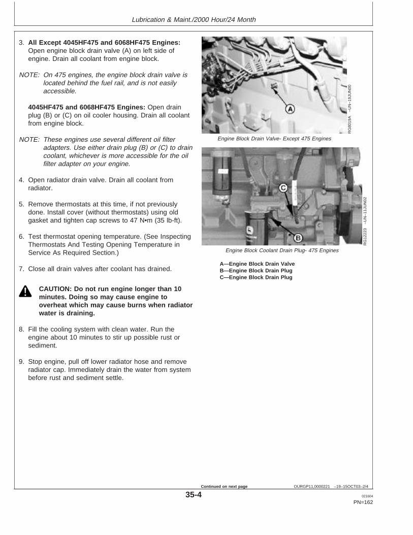
Lubrication & Maint./2000 Hour/24 Month
OURGP11,0000221 –19–15OCT03–2/4
RG
8019
A–U
N–1
9JU
N00
Engine Block Drain Valve- Except 475 Engines
RG
1222
3–U
N–1
1JU
N02
Engine Block Coolant Drain Plug- 475 Engines
A—Engine Block Drain ValveB—Engine Block Drain PlugC—Engine Block Drain Plug
3. All Except 4045HF475 and 6068HF475 Engines:Open engine block drain valve (A) on left side ofengine. Drain all coolant from engine block.
NOTE: On 475 engines, the engine block drain valve islocated behind the fuel rail, and is not easilyaccessible.
4045HF475 and 6068HF475 Engines: Open drainplug (B) or (C) on oil cooler housing. Drain all coolantfrom engine block.
NOTE: These engines use several different oil filteradapters. Use either drain plug (B) or (C) to draincoolant, whichever is more accessible for the oilfilter adapter on your engine.
4. Open radiator drain valve. Drain all coolant fromradiator.
5. Remove thermostats at this time, if not previouslydone. Install cover (without thermostats) using oldgasket and tighten cap screws to 47 N•m (35 lb-ft).
6. Test thermostat opening temperature. (See InspectingThermostats And Testing Opening Temperature inService As Required Section.)
7. Close all drain valves after coolant has drained.
CAUTION: Do not run engine longer than 10minutes. Doing so may cause engine tooverheat which may cause burns when radiatorwater is draining.
8. Fill the cooling system with clean water. Run theengine about 10 minutes to stir up possible rust orsediment.
9. Stop engine, pull off lower radiator hose and removeradiator cap. Immediately drain the water from systembefore rust and sediment settle.
35-4 021604
PN=162
Continued on next page
https://www.truck-manuals.net/
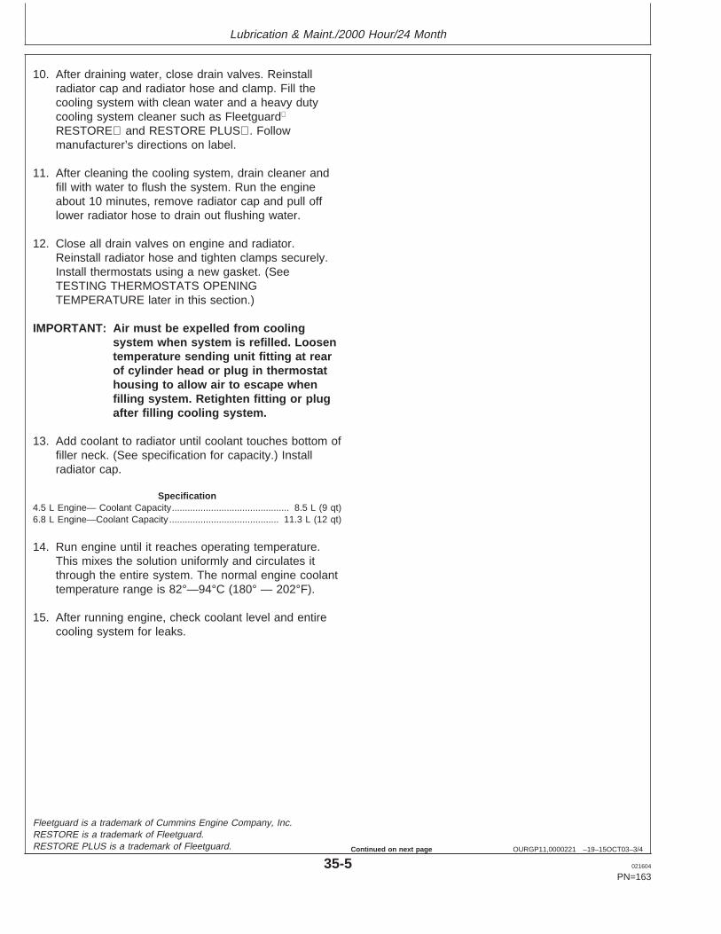
Lubrication & Maint./2000 Hour/24 Month
OURGP11,0000221 –19–15OCT03–3/4
10. After draining water, close drain valves. Reinstallradiator cap and radiator hose and clamp. Fill thecooling system with clean water and a heavy dutycooling system cleaner such as Fleetguard
RESTORE and RESTORE PLUS. Followmanufacturer’s directions on label.
11. After cleaning the cooling system, drain cleaner andfill with water to flush the system. Run the engineabout 10 minutes, remove radiator cap and pull offlower radiator hose to drain out flushing water.
12. Close all drain valves on engine and radiator.Reinstall radiator hose and tighten clamps securely.Install thermostats using a new gasket. (SeeTESTING THERMOSTATS OPENINGTEMPERATURE later in this section.)
IMPORTANT: Air must be expelled from coolingsystem when system is refilled. Loosentemperature sending unit fitting at rearof cylinder head or plug in thermostathousing to allow air to escape whenfilling system. Retighten fitting or plugafter filling cooling system.
13. Add coolant to radiator until coolant touches bottom offiller neck. (See specification for capacity.) Installradiator cap.
Specification4.5 L Engine— Coolant Capacity 8.5 L (9 qt).............................................6.8 L Engine—Coolant Capacity 11.3 L (12 qt)..........................................
14. Run engine until it reaches operating temperature.This mixes the solution uniformly and circulates itthrough the entire system. The normal engine coolanttemperature range is 82°—94°C (180° — 202°F).
15. After running engine, check coolant level and entirecooling system for leaks.
Fleetguard is a trademark of Cummins Engine Company, Inc.RESTORE is a trademark of Fleetguard.RESTORE PLUS is a trademark of Fleetguard.
35-5 021604
PN=163
Continued on next page
https://www.truck-manuals.net/
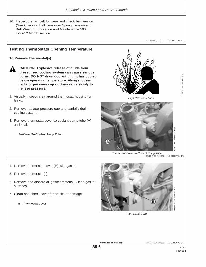
Lubrication & Maint./2000 Hour/24 Month
OURGP11,0000221 –19–15OCT03–4/4
16. Inspect the fan belt for wear and check belt tension.(See Checking Belt Tensioner Spring Tension andBelt Wear in Lubrication and Maintenance 500Hour/12 Month section.
DPSG,RG34710,112 –19–23NOV01–1/5
Testing Thermostats Opening Temperature
TS
281
–UN
–23A
UG
88
High Pressure Fluids
RG
8115
A–U
N–1
5JA
N98
Thermostat Cover-to-Coolant Pump Tube
A—Cover-To-Coolant Pump Tube
To Remove Thermostat(s)
CAUTION: Explosive release of fluids frompressurized cooling system can cause seriousburns. DO NOT drain coolant until it has cooledbelow operating temperature. Always loosenradiator pressure cap or drain valve slowly torelieve pressure.
1. Visually inspect area around thermostat housing forleaks.
2. Remove radiator pressure cap and partially draincooling system.
3. Remove thermostat cover-to-coolant pump tube (A)and seal.
DPSG,RG34710,112 –19–23NOV01–2/5
RG
7921
A–U
N–1
3NO
V97
Thermostat Cover
B—Thermostat Cover
4. Remove thermostat cover (B) with gasket.
5. Remove thermostat(s)
6. Remove and discard all gasket material. Clean gasketsurfaces.
7. Clean and check cover for cracks or damage.
35-6 021604
PN=164
Continued on next page
https://www.truck-manuals.net/
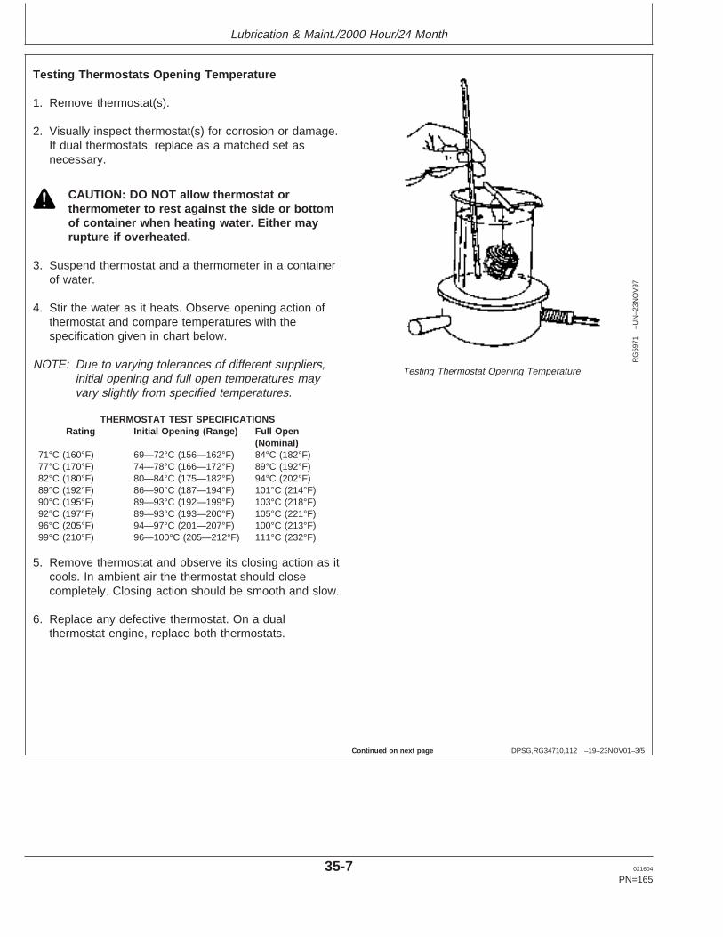
Lubrication & Maint./2000 Hour/24 Month
DPSG,RG34710,112 –19–23NOV01–3/5
RG
5971
–UN
–23N
OV
97
Testing Thermostat Opening Temperature
Testing Thermostats Opening Temperature
1. Remove thermostat(s).
2. Visually inspect thermostat(s) for corrosion or damage.If dual thermostats, replace as a matched set asnecessary.
CAUTION: DO NOT allow thermostat orthermometer to rest against the side or bottomof container when heating water. Either mayrupture if overheated.
3. Suspend thermostat and a thermometer in a containerof water.
4. Stir the water as it heats. Observe opening action ofthermostat and compare temperatures with thespecification given in chart below.
NOTE: Due to varying tolerances of different suppliers,initial opening and full open temperatures mayvary slightly from specified temperatures.
THERMOSTAT TEST SPECIFICATIONSRating Initial Opening (Range) Full Open
(Nominal)71°C (160°F) 69—72°C (156—162°F) 84°C (182°F)77°C (170°F) 74—78°C (166—172°F) 89°C (192°F)82°C (180°F) 80—84°C (175—182°F) 94°C (202°F)89°C (192°F) 86—90°C (187—194°F) 101°C (214°F)90°C (195°F) 89—93°C (192—199°F) 103°C (218°F)92°C (197°F) 89—93°C (193—200°F) 105°C (221°F)96°C (205°F) 94—97°C (201—207°F) 100°C (213°F)99°C (210°F) 96—100°C (205—212°F) 111°C (232°F)
5. Remove thermostat and observe its closing action as itcools. In ambient air the thermostat should closecompletely. Closing action should be smooth and slow.
6. Replace any defective thermostat. On a dualthermostat engine, replace both thermostats.
Continued on next page
35-7 021604
PN=165
https://www.truck-manuals.net/
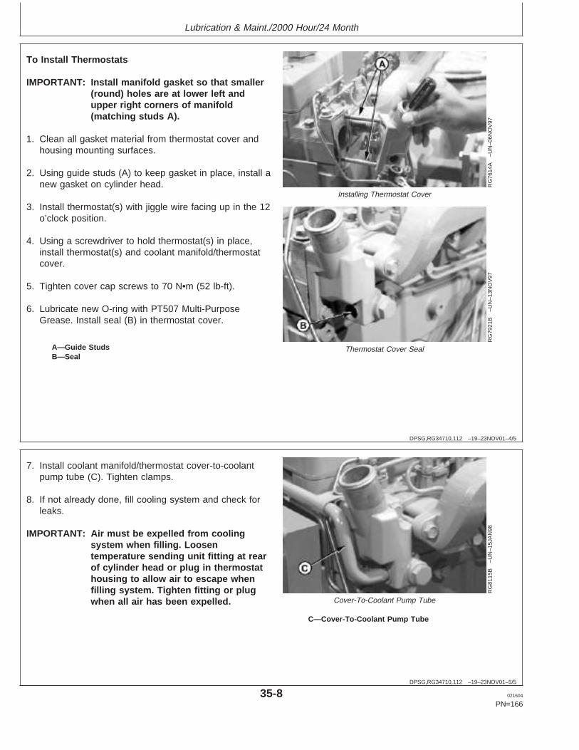
Lubrication & Maint./2000 Hour/24 Month
DPSG,RG34710,112 –19–23NOV01–4/5
RG
7614
A–U
N–0
6NO
V97
Installing Thermostat Cover
RG
7921
B–U
N–1
3NO
V97
Thermostat Cover SealA—Guide StudsB—Seal
To Install Thermostats
IMPORTANT: Install manifold gasket so that smaller(round) holes are at lower left andupper right corners of manifold(matching studs A).
1. Clean all gasket material from thermostat cover andhousing mounting surfaces.
2. Using guide studs (A) to keep gasket in place, install anew gasket on cylinder head.
3. Install thermostat(s) with jiggle wire facing up in the 12o’clock position.
4. Using a screwdriver to hold thermostat(s) in place,install thermostat(s) and coolant manifold/thermostatcover.
5. Tighten cover cap screws to 70 N•m (52 lb-ft).
6. Lubricate new O-ring with PT507 Multi-PurposeGrease. Install seal (B) in thermostat cover.
DPSG,RG34710,112 –19–23NOV01–5/5
RG
8115
B–U
N–1
5JA
N98
Cover-To-Coolant Pump Tube
C—Cover-To-Coolant Pump Tube
7. Install coolant manifold/thermostat cover-to-coolantpump tube (C). Tighten clamps.
8. If not already done, fill cooling system and check forleaks.
IMPORTANT: Air must be expelled from coolingsystem when filling. Loosentemperature sending unit fitting at rearof cylinder head or plug in thermostathousing to allow air to escape whenfilling system. Tighten fitting or plugwhen all air has been expelled.
35-8 021604
PN=166
https://www.truck-manuals.net/
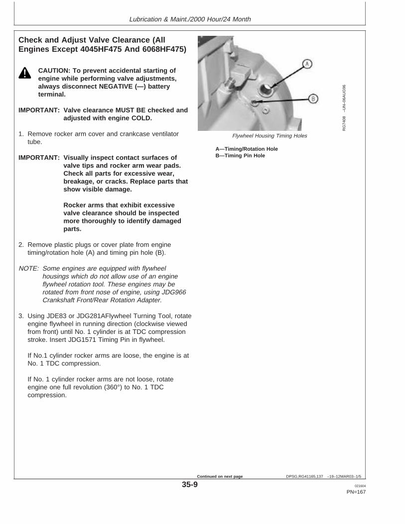
Lubrication & Maint./2000 Hour/24 Month
DPSG,RG41165,137 –19–12MAR03–1/5
Check and Adjust Valve Clearance (AllEngines Except 4045HF475 And 6068HF475)
RG
7408
–UN
–06A
UG
96
Flywheel Housing Timing Holes
A—Timing/Rotation HoleB—Timing Pin Hole
CAUTION: To prevent accidental starting ofengine while performing valve adjustments,always disconnect NEGATIVE (—) batteryterminal.
IMPORTANT: Valve clearance MUST BE checked andadjusted with engine COLD.
1. Remove rocker arm cover and crankcase ventilatortube.
IMPORTANT: Visually inspect contact surfaces ofvalve tips and rocker arm wear pads.Check all parts for excessive wear,breakage, or cracks. Replace parts thatshow visible damage.
Rocker arms that exhibit excessivevalve clearance should be inspectedmore thoroughly to identify damagedparts.
2. Remove plastic plugs or cover plate from enginetiming/rotation hole (A) and timing pin hole (B).
NOTE: Some engines are equipped with flywheelhousings which do not allow use of an engineflywheel rotation tool. These engines may berotated from front nose of engine, using JDG966Crankshaft Front/Rear Rotation Adapter.
3. Using JDE83 or JDG281AFlywheel Turning Tool, rotateengine flywheel in running direction (clockwise viewedfrom front) until No. 1 cylinder is at TDC compressionstroke. Insert JDG1571 Timing Pin in flywheel.
If No.1 cylinder rocker arms are loose, the engine is atNo. 1 TDC compression.
If No. 1 cylinder rocker arms are not loose, rotateengine one full revolution (360°) to No. 1 TDCcompression.
35-9 021604
PN=167
Continued on next page
https://www.truck-manuals.net/
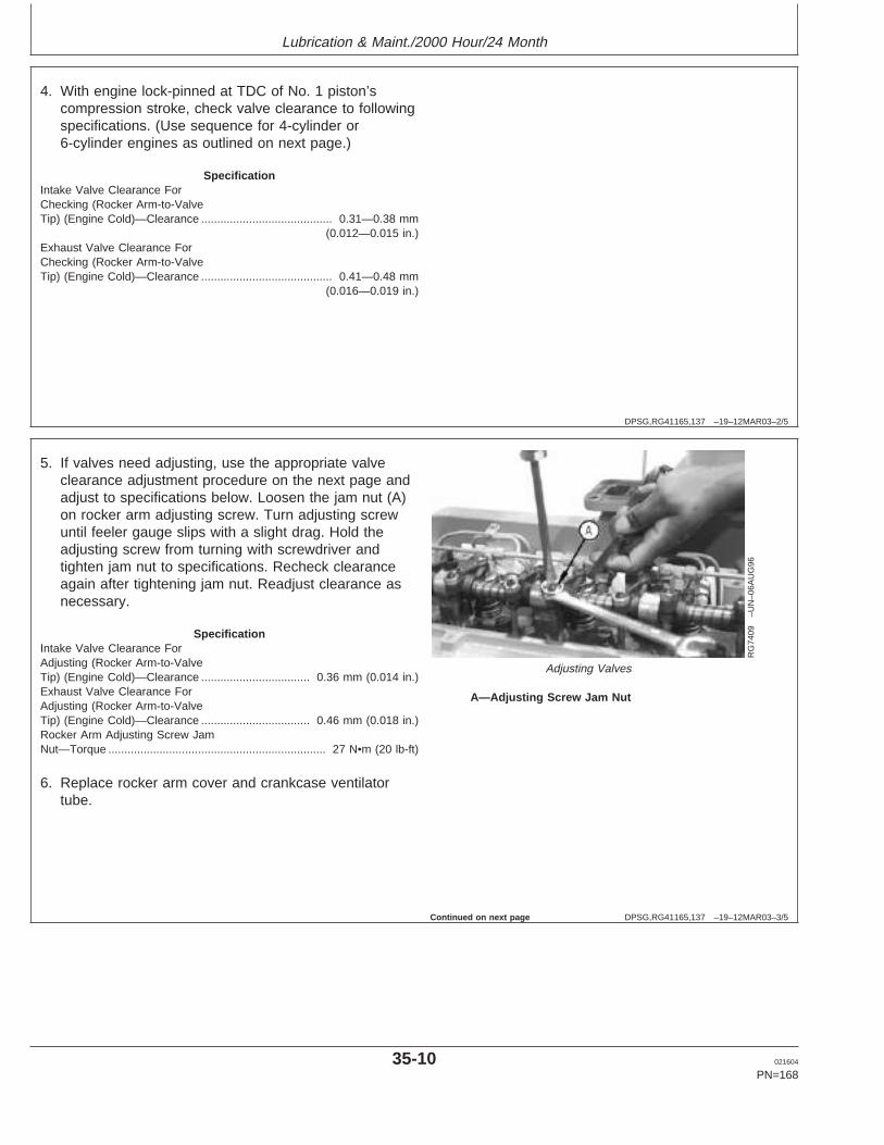
Lubrication & Maint./2000 Hour/24 Month
DPSG,RG41165,137 –19–12MAR03–2/5
4. With engine lock-pinned at TDC of No. 1 piston’scompression stroke, check valve clearance to followingspecifications. (Use sequence for 4-cylinder or6-cylinder engines as outlined on next page.)
SpecificationIntake Valve Clearance ForChecking (Rocker Arm-to-ValveTip) (Engine Cold)—Clearance 0.31—0.38 mm
(0.012—0.015 in.).........................................
Exhaust Valve Clearance ForChecking (Rocker Arm-to-ValveTip) (Engine Cold)—Clearance 0.41—0.48 mm
(0.016—0.019 in.).........................................
DPSG,RG41165,137 –19–12MAR03–3/5
RG
7409
–UN
–06A
UG
96
Adjusting Valves
A—Adjusting Screw Jam Nut
5. If valves need adjusting, use the appropriate valveclearance adjustment procedure on the next page andadjust to specifications below. Loosen the jam nut (A)on rocker arm adjusting screw. Turn adjusting screwuntil feeler gauge slips with a slight drag. Hold theadjusting screw from turning with screwdriver andtighten jam nut to specifications. Recheck clearanceagain after tightening jam nut. Readjust clearance asnecessary.
SpecificationIntake Valve Clearance ForAdjusting (Rocker Arm-to-ValveTip) (Engine Cold)—Clearance 0.36 mm (0.014 in.)..................................Exhaust Valve Clearance ForAdjusting (Rocker Arm-to-ValveTip) (Engine Cold)—Clearance 0.46 mm (0.018 in.)..................................Rocker Arm Adjusting Screw JamNut—Torque 27 N•m (20 lb-ft)....................................................................
6. Replace rocker arm cover and crankcase ventilatortube.
Continued on next page
35-10 021604
PN=168
https://www.truck-manuals.net/
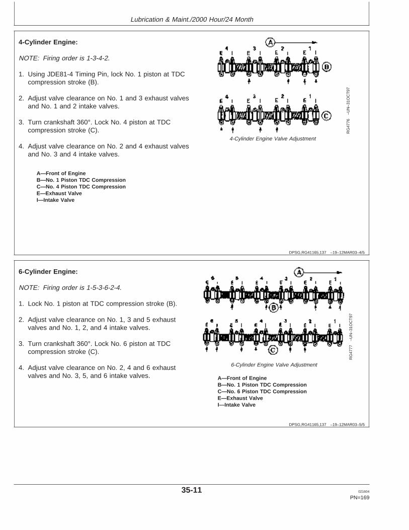
Lubrication & Maint./2000 Hour/24 Month
DPSG,RG41165,137 –19–12MAR03–4/5
RG
4776
–UN
–31O
CT
97
4-Cylinder Engine Valve Adjustment
A—Front of EngineB—No. 1 Piston TDC CompressionC—No. 4 Piston TDC CompressionE—Exhaust ValveI—Intake Valve
4-Cylinder Engine:
NOTE: Firing order is 1-3-4-2.
1. Using JDE81-4 Timing Pin, lock No. 1 piston at TDCcompression stroke (B).
2. Adjust valve clearance on No. 1 and 3 exhaust valvesand No. 1 and 2 intake valves.
3. Turn crankshaft 360°. Lock No. 4 piston at TDCcompression stroke (C).
4. Adjust valve clearance on No. 2 and 4 exhaust valvesand No. 3 and 4 intake valves.
DPSG,RG41165,137 –19–12MAR03–5/5
RG
4777
–UN
–31O
CT
97
6-Cylinder Engine Valve Adjustment
A—Front of EngineB—No. 1 Piston TDC CompressionC—No. 6 Piston TDC CompressionE—Exhaust ValveI—Intake Valve
6-Cylinder Engine:
NOTE: Firing order is 1-5-3-6-2-4.
1. Lock No. 1 piston at TDC compression stroke (B).
2. Adjust valve clearance on No. 1, 3 and 5 exhaustvalves and No. 1, 2, and 4 intake valves.
3. Turn crankshaft 360°. Lock No. 6 piston at TDCcompression stroke (C).
4. Adjust valve clearance on No. 2, 4 and 6 exhaustvalves and No. 3, 5, and 6 intake valves.
35-11 021604
PN=169
https://www.truck-manuals.net/
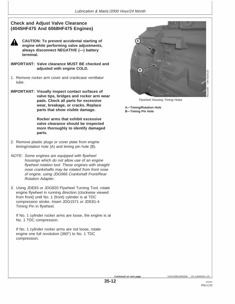
Lubrication & Maint./2000 Hour/24 Month
OUO1089,0000208 –19–12MAR03–1/5
Check and Adjust Valve Clearance(4045HF475 And 6068HF475 Engines)
RG
1216
8–U
N–0
3JU
L02
Flywheel Housing Timing Holes
A—Timing/Rotation HoleB—Timing Pin Hole
CAUTION: To prevent accidental starting ofengine while performing valve adjustments,always disconnect NEGATIVE (—) batteryterminal.
IMPORTANT: Valve clearance MUST BE checked andadjusted with engine COLD.
1. Remove rocker arm cover and crankcase ventilatortube.
IMPORTANT: Visually inspect contact surfaces ofvalve tips, bridges and rocker arm wearpads. Check all parts for excessivewear, breakage, or cracks. Replaceparts that show visible damage.
Rocker arms that exhibit excessivevalve clearance should be inspectedmore thoroughly to identify damagedparts.
2. Remove plastic plugs or cover plate from enginetiming/rotation hole (A) and timing pin hole (B).
NOTE: Some engines are equipped with flywheelhousings which do not allow use of an engineflywheel rotation tool. These engines with straightnose crankshafts may be rotated from front noseof engine, using JDG966 Crankshaft Front/RearRotation Adapter.
3. Using JDE83 or JDG820 Flywheel Turning Tool, rotateengine flywheel in running direction (clockwise viewedfrom front) until No. 1 (front) cylinder is at TDCcompression stroke. Insert JDG1571 or JDE81-4Timing Pin in flywheel.
If No. 1 cylinder rocker arms are loose, the engine is atNo. 1 TDC compression.
If No. 1 cylinder rocker arms are not loose, rotateengine one full revolution (360°) to No. 1 TDCcompression.
35-12 021604
PN=170
Continued on next page
https://www.truck-manuals.net/
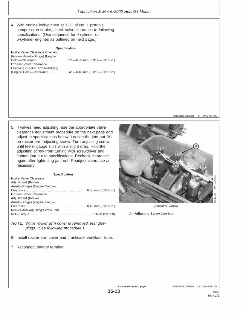
Lubrication & Maint./2000 Hour/24 Month
OUO1089,0000208 –19–12MAR03–2/5
4. With engine lock-pinned at TDC of No. 1 piston’scompression stroke, check valve clearance to followingspecifications. (Use sequence for 4-cylinder or6-cylinder engines as outlined on next page.)
SpecificationIntake Valve Clearance Checking(Rocker Arm-to-Bridge) (EngineCold)—Clearance 0.31—0.38 mm (0.012—0.015 in.)................................Exhaust Valve ClearanceChecking (Rocker Arm-to-Bridge)(Engine Cold)—Clearance 0.41—0.48 mm (0.016—0.019 in.)...................
OUO1089,0000208 –19–12MAR03–3/5
RG
1216
9–U
N–0
3JU
L02
Adjusting Valves
A—Adjusting Screw Jam Nut
5. If valves need adjusting, use the appropriate valveclearance adjustment procedure on the next page andadjust to specifications below. Loosen the jam nut (A)on rocker arm adjusting screw. Turn adjusting screwuntil feeler gauge slips with a slight drag. Hold theadjusting screw from turning with screwdriver andtighten jam nut to specifications. Recheck clearanceagain after tightening jam nut. Readjust clearance asnecessary.
SpecificationIntake Valve ClearanceAdjustment (RockerArm-to-Bridge) (Engine Cold)—Clearance 0.36 mm (0.014 in.)...................................................................Exhaust Valve ClearanceAdjustment (RockerArm-to-Bridge) (Engine Cold)—Clearance 0.46 mm (0.018 in.)...................................................................Rocker Arm Adjusting Screw JamNut—Torque 27 N•m (20 lb-ft)....................................................................
NOTE: While rocker arm cover is removed, test glowplugs. (See following procedure.)
6. Install rocker arm cover and crankcase ventilator tube.
7. Reconnect battery terminal.
35-13 021604
PN=171
Continued on next page
https://www.truck-manuals.net/
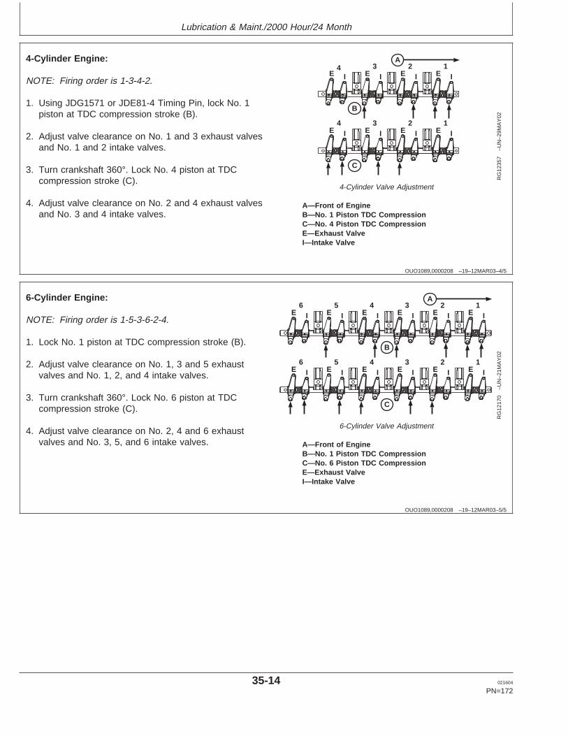
Lubrication & Maint./2000 Hour/24 Month
OUO1089,0000208 –19–12MAR03–4/5
A
B
E I4
E3
I E2
I E1
I
E4
I E3
I E2
I E1
I
C
RG
1235
7–U
N–2
9MA
Y02
4-Cylinder Valve Adjustment
A—Front of EngineB—No. 1 Piston TDC CompressionC—No. 4 Piston TDC CompressionE—Exhaust ValveI—Intake Valve
4-Cylinder Engine:
NOTE: Firing order is 1-3-4-2.
1. Using JDG1571 or JDE81-4 Timing Pin, lock No. 1piston at TDC compression stroke (B).
2. Adjust valve clearance on No. 1 and 3 exhaust valvesand No. 1 and 2 intake valves.
3. Turn crankshaft 360°. Lock No. 4 piston at TDCcompression stroke (C).
4. Adjust valve clearance on No. 2 and 4 exhaust valvesand No. 3 and 4 intake valves.
OUO1089,0000208 –19–12MAR03–5/5
A
B
E6
I E5
I E4
I E3
I E2
I E1
I
E6
I E5
I E4
I E3
I E2
I E1
I
C
RG
1217
0–U
N–2
1MA
Y02
6-Cylinder Valve Adjustment
A—Front of EngineB—No. 1 Piston TDC CompressionC—No. 6 Piston TDC CompressionE—Exhaust ValveI—Intake Valve
6-Cylinder Engine:
NOTE: Firing order is 1-5-3-6-2-4.
1. Lock No. 1 piston at TDC compression stroke (B).
2. Adjust valve clearance on No. 1, 3 and 5 exhaustvalves and No. 1, 2, and 4 intake valves.
3. Turn crankshaft 360°. Lock No. 6 piston at TDCcompression stroke (C).
4. Adjust valve clearance on No. 2, 4 and 6 exhaustvalves and No. 3, 5, and 6 intake valves.
35-14 021604
PN=172
https://www.truck-manuals.net/
Lubrication & Maint./2000 Hour/24 Month
OUOD006,0000018 –19–05JUN02–1/1
Test Glow Plugs for Continuity (4045HF475And 6068HF475 Engines)
CAUTION: To prevent accidental starting ofengine while performing this test, alwaysdisconnect NEGATIVE (—) battery terminal.
While checking valve clearance with rocker arm coverremoved, check each glow plug for continuity using amultimeter.
Check continuity between glow plug and ground oncylinder head. If resistance is infinite (no current), the glowplug is damaged and must be replaced.
Install new glow plugs and torque to specifications.
SpecificationGlow Plug—Torque 12—18 N•m (9—13 lb-ft)............................................
Reinstall rocker arm cover and crankcase ventilator tube.
35-15 021604
PN=173
https://www.truck-manuals.net/
Service as Required
RG,RG34710,5591 –19–23NOV01–1/1
Additional Service Information
RG
4624
–UN
–15D
EC
88
Component Technical Manual
This is not a detailed service manual. If you want moredetailed service information, use the PublicationsInformation in the back of this manual to order acomponent technical manual.
40-1 021604
PN=174
https://www.truck-manuals.net/
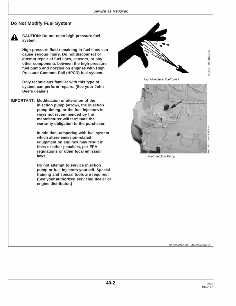
Service as Required
RG,RG34710,5592 –19–25MAR03–1/1
Do Not Modify Fuel System
TS
1343
–UN
–18M
AR
92
High-Pressure Fuel Lines
RG
1195
3–U
N–2
6NO
V01
Fuel Injection Pump
CAUTION: Do not open high-pressure fuelsystem.
High-pressure fluid remaining in fuel lines cancause serious injury. Do not disconnect orattempt repair of fuel lines, sensors, or anyother components between the high-pressurefuel pump and nozzles on engines with HighPressure Common Rail (HPCR) fuel system.
Only technicians familiar with this type ofsystem can perform repairs. (See your JohnDeere dealer.)
IMPORTANT: Modification or alteration of theinjection pump (arrow), the injectionpump timing, or the fuel injectors inways not recommended by themanufacturer will terminate thewarranty obligation to the purchaser.
In addition, tampering with fuel systemwhich alters emission-relatedequipment on engines may result infines or other penalties, per EPAregulations or other local emissionlaws.
Do not attempt to service injectionpump or fuel injectors yourself. Specialtraining and special tools are required.(See your authorized servicing dealer orengine distributor.)
40-2 021604
PN=175
https://www.truck-manuals.net/
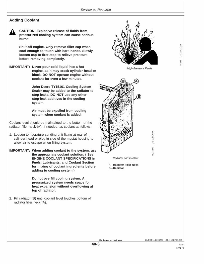
Service as Required
OURGP11,0000222 –19–15OCT03–1/2
Adding Coolant
TS
281
–UN
–23A
UG
88
High-Pressure Fluids
RG
1329
5–U
N–2
0NO
V03
Radiator and Coolant
A—Radiator Filler NeckB—Radiator
CAUTION: Explosive release of fluids frompressurized cooling system can cause seriousburns.
Shut off engine. Only remove filler cap whencool enough to touch with bare hands. Slowlyloosen cap to first stop to relieve pressurebefore removing completely.
IMPORTANT: Never pour cold liquid into a hotengine, as it may crack cylinder head orblock. DO NOT operate engine withoutcoolant for even a few minutes.
John Deere TY15161 Cooling SystemSealer may be added to the radiator tostop leaks. DO NOT use any otherstop-leak additives in the coolingsystem.
Air must be expelled from coolingsystem when coolant is added.
Coolant level should be maintained to the bottom of theradiator filler neck (A). If needed, as coolant as follows.
1. Loosen temperature sending unit fitting at rear ofcylinder head or plug in side of thermostat housing toallow air to escape when filling system.
IMPORTANT: When adding coolant to the system, usethe appropriate coolant solution. ( SeeENGINE COOLANT SPECIFICATIONS inFuels, Lubricants, and Coolant Sectionfor mixing of coolant ingredients beforeadding to cooling system.)
Do not overfill cooling system. Apressurized system needs space forheat expansion without overflowing attop of radiator.
2. Fill radiator (B) until coolant level touches bottom ofradiator filler neck (A).
40-3 021604
PN=176
Continued on next page
https://www.truck-manuals.net/
Service as Required
OURGP11,0000222 –19–15OCT03–2/2
3. Tighten plugs and fittings when air has been expelledfrom system.
4. Run engine until it reaches operating temperature.
40-4 021604
PN=177
https://www.truck-manuals.net/
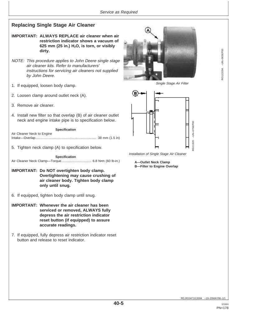
Service as Required
RG,RG34710,5594 –19–20MAY96–1/1
Replacing Single Stage Air Cleaner
RG
1131
9A–U
N–0
6SE
P00
Single Stage Air Filter
RG
1132
0–U
N–0
7SE
P00
Installation of Single Stage Air Cleaner
A—Outlet Neck ClampB—Filter to Engine Overlap
IMPORTANT: ALWAYS REPLACE air cleaner when airrestriction indicator shows a vacuum of625 mm (25 in.) H 2O, is torn, or visiblydirty.
NOTE: This procedure applies to John Deere single stageair cleaner kits. Refer to manufacturers’instructions for servicing air cleaners not suppliedby John Deere.
1. If equipped, loosen body clamp.
2. Loosen clamp around outlet neck (A).
3. Remove air cleaner.
4. Install new filter so that overlap (B) of air cleaner outletneck and engine intake pipe is to specification below.
SpecificationAir Cleaner Neck to EngineIntake—Overlap 38 mm (1.5 in)..................................................................
5. Tighten neck clamp (A) to specification below.
SpecificationAir Cleaner Neck Clamp—Torque 6.8 N•m (60 lb-in.).................................
IMPORTANT: Do NOT overtighten body clamp.Overtightening may cause crushing ofair cleaner body. Tighten body clamponly until snug.
6. If equipped, tighten body clamp until snug.
IMPORTANT: Whenever the air cleaner has beenserviced or removed, ALWAYS fullydepress the air restriction indicatorreset button (if equipped) to assureaccurate readings.
7. If equipped, fully depress air restriction indicator resetbutton and release to reset indicator.
40-5 021604
PN=178
https://www.truck-manuals.net/
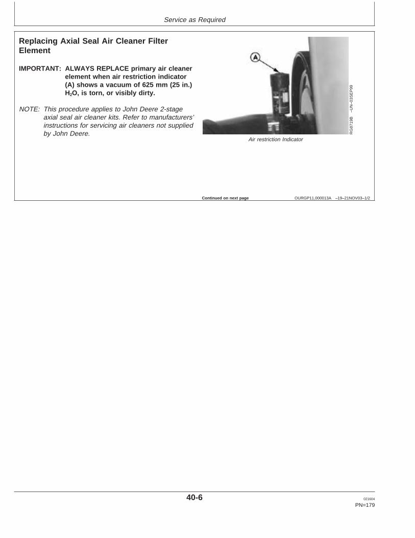
Service as Required
OURGP11,000013A –19–21NOV03–1/2
Replacing Axial Seal Air Cleaner FilterElement
RG
8719
B–U
N–0
3SE
P99
Air restriction Indicator
IMPORTANT: ALWAYS REPLACE primary air cleanerelement when air restriction indicator(A) shows a vacuum of 625 mm (25 in.)H2O, is torn, or visibly dirty.
NOTE: This procedure applies to John Deere 2-stageaxial seal air cleaner kits. Refer to manufacturers’instructions for servicing air cleaners not suppliedby John Deere.
Continued on next page
40-6 021604
PN=179
https://www.truck-manuals.net/
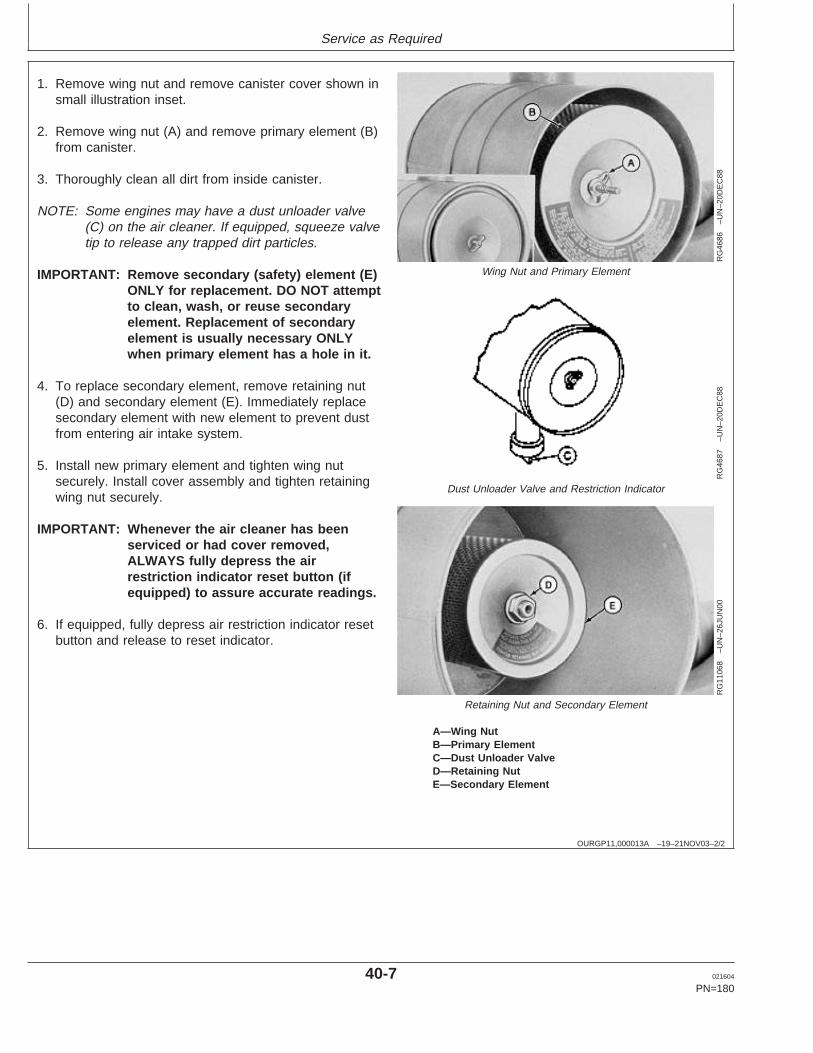
Service as Required
OURGP11,000013A –19–21NOV03–2/2
RG
4686
–UN
–20D
EC
88
Wing Nut and Primary Element
RG
4687
–UN
–20D
EC
88
Dust Unloader Valve and Restriction Indicator
RG
1106
8–U
N–2
6JU
N00
Retaining Nut and Secondary Element
A—Wing NutB—Primary ElementC—Dust Unloader ValveD—Retaining NutE—Secondary Element
1. Remove wing nut and remove canister cover shown insmall illustration inset.
2. Remove wing nut (A) and remove primary element (B)from canister.
3. Thoroughly clean all dirt from inside canister.
NOTE: Some engines may have a dust unloader valve(C) on the air cleaner. If equipped, squeeze valvetip to release any trapped dirt particles.
IMPORTANT: Remove secondary (safety) element (E)ONLY for replacement. DO NOT attemptto clean, wash, or reuse secondaryelement. Replacement of secondaryelement is usually necessary ONLYwhen primary element has a hole in it.
4. To replace secondary element, remove retaining nut(D) and secondary element (E). Immediately replacesecondary element with new element to prevent dustfrom entering air intake system.
5. Install new primary element and tighten wing nutsecurely. Install cover assembly and tighten retainingwing nut securely.
IMPORTANT: Whenever the air cleaner has beenserviced or had cover removed,ALWAYS fully depress the airrestriction indicator reset button (ifequipped) to assure accurate readings.
6. If equipped, fully depress air restriction indicator resetbutton and release to reset indicator.
40-7 021604
PN=180
https://www.truck-manuals.net/
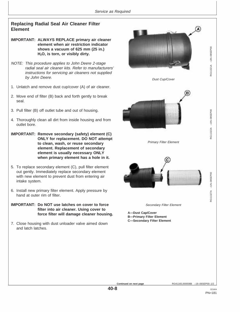
Service as Required
RG41165,000008B –19–06SEP00–1/2
Replacing Radial Seal Air Cleaner FilterElement
RG
1132
1A–U
N–0
8SE
P00
Dust Cup/Cover
RG
1132
2A–U
N–0
8SE
P00
Primary Filter Element
RG
1132
7A–U
N–0
8SE
P00
Secondary Filter Element
A—Dust Cap/CoverB—Primary Filter ElementC—Secondary Filter Element
IMPORTANT: ALWAYS REPLACE primary air cleanerelement when air restriction indicatorshows a vacuum of 625 mm (25 in.)H2O, is torn, or visibly dirty.
NOTE: This procedure applies to John Deere 2-stageradial seal air cleaner kits. Refer to manufacturers’instructions for servicing air cleaners not suppliedby John Deere.
1. Unlatch and remove dust cup/cover (A) of air cleaner.
2. Move end of filter (B) back and forth gently to breakseal.
3. Pull filter (B) off outlet tube and out of housing.
4. Thoroughly clean all dirt from inside housing and fromoutlet bore.
IMPORTANT: Remove secondary (safety) element (C)ONLY for replacement. DO NOT attemptto clean, wash, or reuse secondaryelement. Replacement of secondaryelement is usually necessary ONLYwhen primary element has a hole in it.
5. To replace secondary element (C), pull filter elementout gently. Immediately replace secondary elementwith new element to prevent dust from entering airintake system.
6. Install new primary filter element. Apply pressure byhand at outer rim of filter.
IMPORTANT: Do NOT use latches on cover to forcefilter into air cleaner. Using cover toforce filter will damage cleaner housing.
7. Close housing with dust unloader valve aimed downand latch latches.
40-8 021604
PN=181
Continued on next page
https://www.truck-manuals.net/
Service as Required
RG41165,000008B –19–06SEP00–2/2
IMPORTANT: Whenever the air cleaner has beenserviced or cover has been removed,ALWAYS fully depress the airrestriction indicator reset button (ifequipped) to assure accurate readings.
8. If equipped, fully depress air restriction indicator resetbutton and release to reset indicator.
40-9 021604
PN=182
https://www.truck-manuals.net/
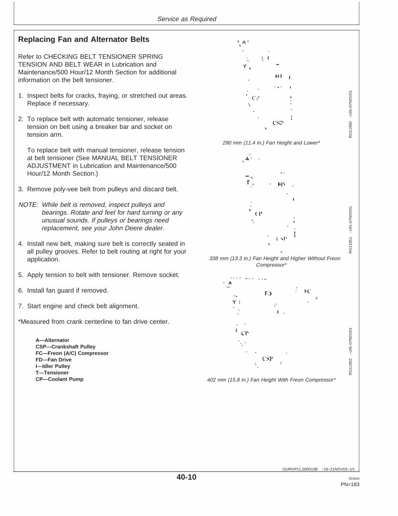
Service as Required
OURGP11,000013B –19–21NOV03–1/1
Replacing Fan and Alternator Belts
RG
1195
0–U
N–0
7NO
V01
290 mm (11.4 in.) Fan Height and Lower*
RG
1195
1–U
N–0
7NO
V01
338 mm (13.3 in.) Fan Height and Higher Without FreonCompressor*
RG
1195
2–U
N–0
7NO
V01
402 mm (15.8 in.) Fan Height With Freon Compressor*
A—AlternatorCSP—Crankshaft PulleyFC—Freon (A/C) CompressorFD—Fan DriveI—Idler PulleyT—TensionerCP—Coolant Pump
Refer to CHECKING BELT TENSIONER SPRINGTENSION AND BELT WEAR in Lubrication andMaintenance/500 Hour/12 Month Section for additionalinformation on the belt tensioner.
1. Inspect belts for cracks, fraying, or stretched out areas.Replace if necessary.
2. To replace belt with automatic tensioner, releasetension on belt using a breaker bar and socket ontension arm.
To replace belt with manual tensioner, release tensionat belt tensioner (See MANUAL BELT TENSIONERADJUSTMENT in Lubrication and Maintenance/500Hour/12 Month Section.)
3. Remove poly-vee belt from pulleys and discard belt.
NOTE: While belt is removed, inspect pulleys andbearings. Rotate and feel for hard turning or anyunusual sounds. If pulleys or bearings needreplacement, see your John Deere dealer.
4. Install new belt, making sure belt is correctly seated inall pulley grooves. Refer to belt routing at right for yourapplication.
5. Apply tension to belt with tensioner. Remove socket.
6. Install fan guard if removed.
7. Start engine and check belt alignment.
*Measured from crank centerline to fan drive center.
40-10 021604
PN=183
https://www.truck-manuals.net/
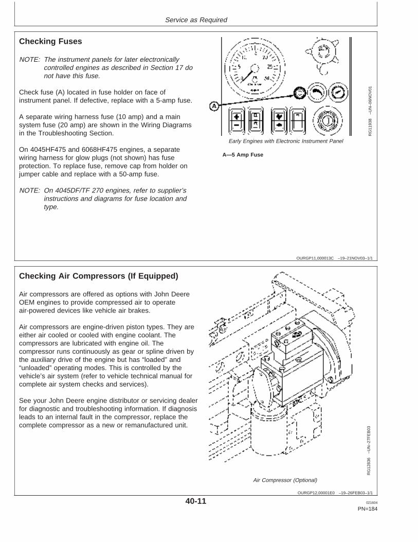
Service as Required
OURGP11,000013C –19–21NOV03–1/1
Checking Fuses
RG
1193
8–U
N–0
6NO
V01
Early Engines with Electronic Instrument Panel
A—5 Amp Fuse
NOTE: The instrument panels for later electronicallycontrolled engines as described in Section 17 donot have this fuse.
Check fuse (A) located in fuse holder on face ofinstrument panel. If defective, replace with a 5-amp fuse.
A separate wiring harness fuse (10 amp) and a mainsystem fuse (20 amp) are shown in the Wiring Diagramsin the Troubleshooting Section.
On 4045HF475 and 6068HF475 engines, a separatewiring harness for glow plugs (not shown) has fuseprotection. To replace fuse, remove cap from holder onjumper cable and replace with a 50-amp fuse.
NOTE: On 4045DF/TF 270 engines, refer to supplier’sinstructions and diagrams for fuse location andtype.
OURGP12,00001E0 –19–26FEB03–1/1
Checking Air Compressors (If Equipped)
RG
1283
6–U
N–2
7FE
B03
Air Compressor (Optional)
Air compressors are offered as options with John DeereOEM engines to provide compressed air to operateair-powered devices like vehicle air brakes.
Air compressors are engine-driven piston types. They areeither air cooled or cooled with engine coolant. Thecompressors are lubricated with engine oil. Thecompressor runs continuously as gear or spline driven bythe auxiliary drive of the engine but has “loaded” and“unloaded” operating modes. This is controlled by thevehicle’s air system (refer to vehicle technical manual forcomplete air system checks and services).
See your John Deere engine distributor or servicing dealerfor diagnostic and troubleshooting information. If diagnosisleads to an internal fault in the compressor, replace thecomplete compressor as a new or remanufactured unit.
40-11 021604
PN=184
https://www.truck-manuals.net/
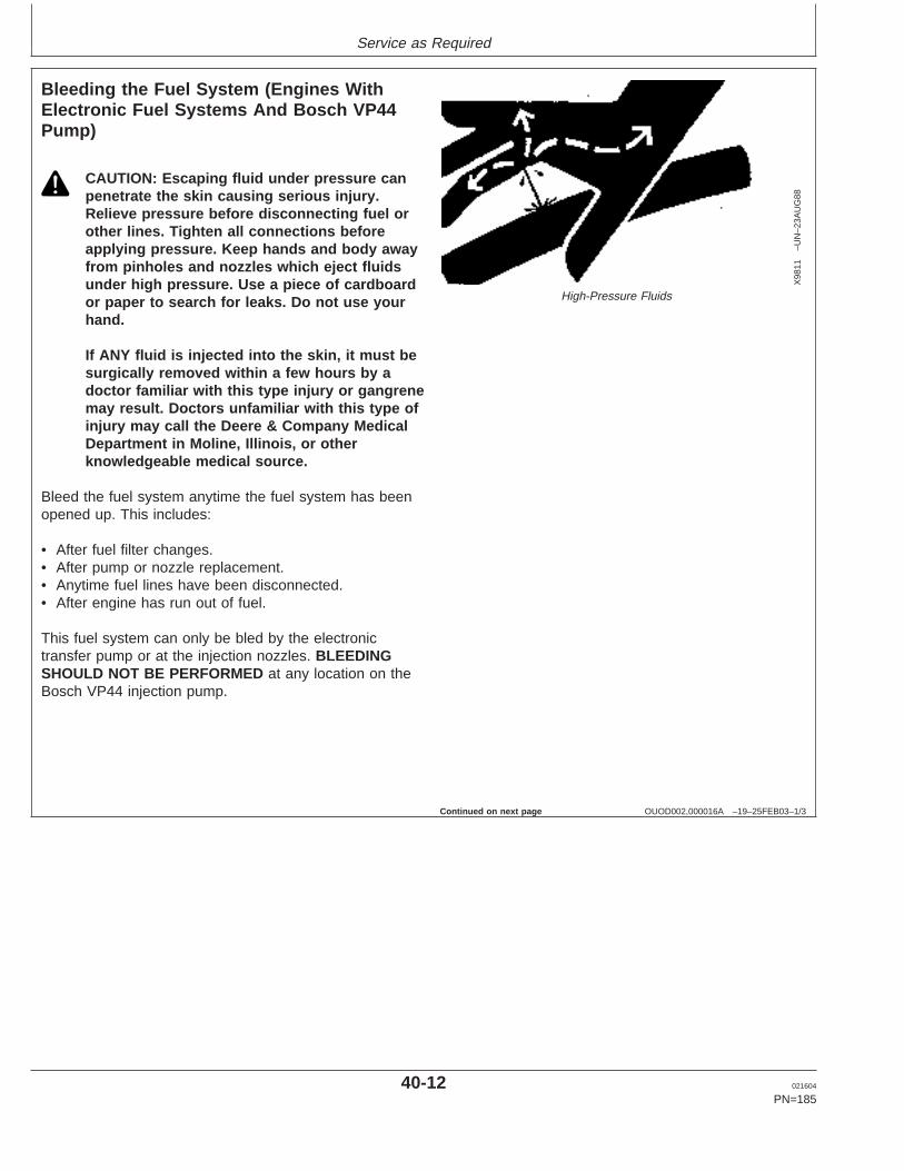
Service as Required
OUOD002,000016A –19–25FEB03–1/3
Bleeding the Fuel System (Engines WithElectronic Fuel Systems And Bosch VP44Pump)
X98
11–U
N–2
3AU
G88
High-Pressure Fluids
CAUTION: Escaping fluid under pressure canpenetrate the skin causing serious injury.Relieve pressure before disconnecting fuel orother lines. Tighten all connections beforeapplying pressure. Keep hands and body awayfrom pinholes and nozzles which eject fluidsunder high pressure. Use a piece of cardboardor paper to search for leaks. Do not use yourhand.
If ANY fluid is injected into the skin, it must besurgically removed within a few hours by adoctor familiar with this type injury or gangrenemay result. Doctors unfamiliar with this type ofinjury may call the Deere & Company MedicalDepartment in Moline, Illinois, or otherknowledgeable medical source.
Bleed the fuel system anytime the fuel system has beenopened up. This includes:
• After fuel filter changes.• After pump or nozzle replacement.• Anytime fuel lines have been disconnected.• After engine has run out of fuel.
This fuel system can only be bled by the electronictransfer pump or at the injection nozzles. BLEEDINGSHOULD NOT BE PERFORMED at any location on theBosch VP44 injection pump.
Continued on next page
40-12 021604
PN=185
https://www.truck-manuals.net/
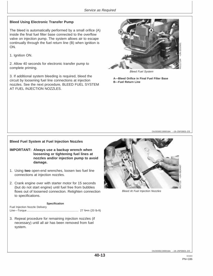
Service as Required
OUOD002,000016A –19–25FEB03–2/3
RG
1171
9A–U
N–2
0JU
N01
Bleed Fuel System
A—Bleed Orifice in Final Fuel Filter BaseB—Fuel Return Line
Bleed Using Electronic Transfer Pump
The bleed is automatically performed by a small orifice (A)inside the final fuel filter base connected to the overflowvalve on injection pump. The system allows air to escapecontinually through the fuel return line (B) when ignition isON.
1. Ignition ON.
2. Allow 40 seconds for electronic transfer pump tocomplete priming.
3. If additional system bleeding is required, bleed thecircuit by loosening fuel line connections at injectionnozzles. See the next procedure, BLEED FUEL SYSTEMAT FUEL INJECTION NOZZLES.
OUOD002,000016A –19–25FEB03–3/3
RG
7725
–UN
–08J
AN
97
Bleed At Fuel Injection Nozzles
Bleed Fuel System at Fuel Injection Nozzles
IMPORTANT: Always use a backup wrench whenloosening or tightening fuel lines atnozzles and/or injection pump to avoiddamage.
1. Using two open-end wrenches, loosen two fuel lineconnections at injection nozzles.
2. Crank engine over with starter motor for 15 seconds(but do not start engine) until fuel free from bubblesflows out of loosened connection. Retighten connectionto specifications.
SpecificationFuel Injection Nozzle DeliveryLine—Torque 27 N•m (20 lb-ft)...................................................................
3. Repeat procedure for remaining injection nozzles (ifnecessary) until all air has been removed from fuelsystem.
40-13 021604
PN=186
https://www.truck-manuals.net/
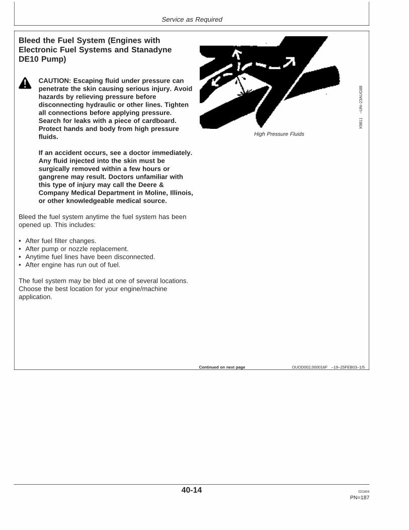
Service as Required
OUOD002,000016F –19–25FEB03–1/5
Bleed the Fuel System (Engines withElectronic Fuel Systems and StanadyneDE10 Pump)
X98
11–U
N–2
3AU
G88
High Pressure Fluids
CAUTION: Escaping fluid under pressure canpenetrate the skin causing serious injury. Avoidhazards by relieving pressure beforedisconnecting hydraulic or other lines. Tightenall connections before applying pressure.Search for leaks with a piece of cardboard.Protect hands and body from high pressurefluids.
If an accident occurs, see a doctor immediately.Any fluid injected into the skin must besurgically removed within a few hours organgrene may result. Doctors unfamiliar withthis type of injury may call the Deere &Company Medical Department in Moline, Illinois,or other knowledgeable medical source.
Bleed the fuel system anytime the fuel system has beenopened up. This includes:
• After fuel filter changes.• After pump or nozzle replacement.• Anytime fuel lines have been disconnected.• After engine has run out of fuel.
The fuel system may be bled at one of several locations.Choose the best location for your engine/machineapplication.
Continued on next page
40-14 021604
PN=187
https://www.truck-manuals.net/
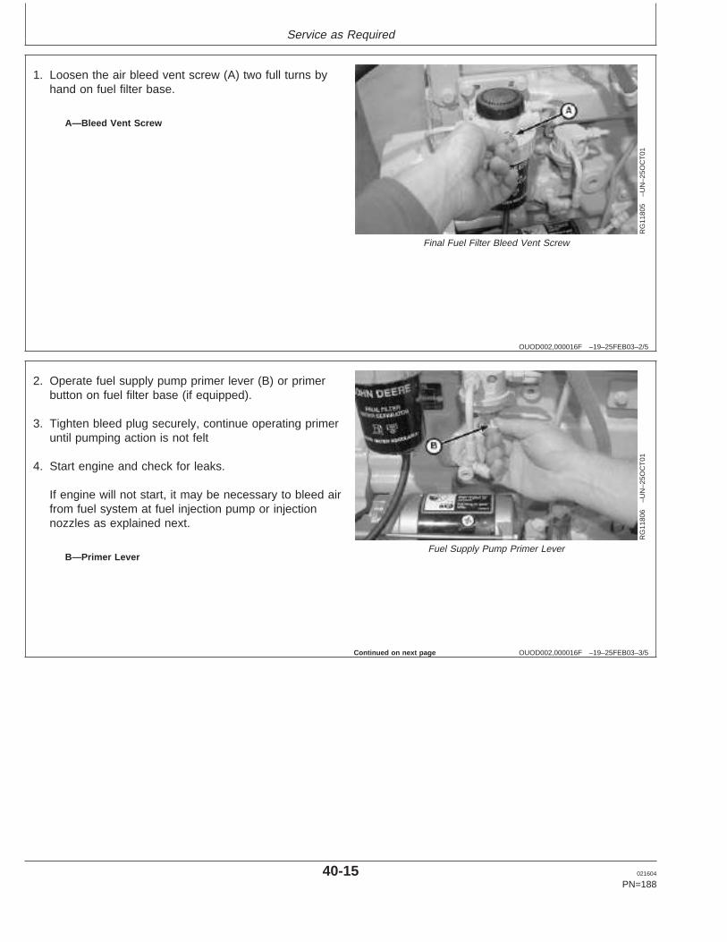
Service as Required
OUOD002,000016F –19–25FEB03–2/5
RG
1180
5–U
N–2
5OC
T01
Final Fuel Filter Bleed Vent Screw
A—Bleed Vent Screw
1. Loosen the air bleed vent screw (A) two full turns byhand on fuel filter base.
OUOD002,000016F –19–25FEB03–3/5
RG
1180
6–U
N–2
5OC
T01
Fuel Supply Pump Primer LeverB—Primer Lever
2. Operate fuel supply pump primer lever (B) or primerbutton on fuel filter base (if equipped).
3. Tighten bleed plug securely, continue operating primeruntil pumping action is not felt
4. Start engine and check for leaks.
If engine will not start, it may be necessary to bleed airfrom fuel system at fuel injection pump or injectionnozzles as explained next.
Continued on next page
40-15 021604
PN=188
https://www.truck-manuals.net/
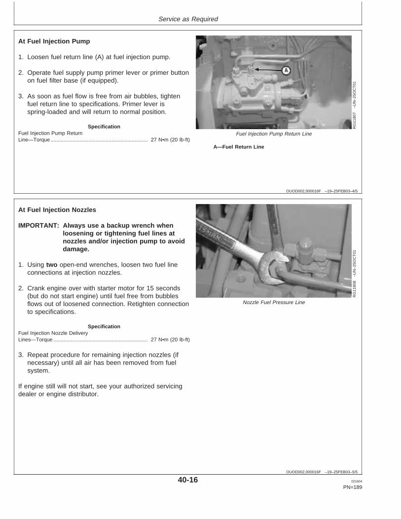
Service as Required
OUOD002,000016F –19–25FEB03–4/5
RG
1180
7–U
N–2
5OC
T01
Fuel Injection Pump Return Line
A—Fuel Return Line
At Fuel Injection Pump
1. Loosen fuel return line (A) at fuel injection pump.
2. Operate fuel supply pump primer lever or primer buttonon fuel filter base (if equipped).
3. As soon as fuel flow is free from air bubbles, tightenfuel return line to specifications. Primer lever isspring-loaded and will return to normal position.
SpecificationFuel Injection Pump ReturnLine—Torque 27 N•m (20 lb-ft)...................................................................
OUOD002,000016F –19–25FEB03–5/5
RG
1180
8–U
N–2
5OC
T01
Nozzle Fuel Pressure Line
At Fuel Injection Nozzles
IMPORTANT: Always use a backup wrench whenloosening or tightening fuel lines atnozzles and/or injection pump to avoiddamage.
1. Using two open-end wrenches, loosen two fuel lineconnections at injection nozzles.
2. Crank engine over with starter motor for 15 seconds(but do not start engine) until fuel free from bubblesflows out of loosened connection. Retighten connectionto specifications.
SpecificationFuel Injection Nozzle DeliveryLines—Torque 27 N•m (20 lb-ft).................................................................
3. Repeat procedure for remaining injection nozzles (ifnecessary) until all air has been removed from fuelsystem.
If engine still will not start, see your authorized servicingdealer or engine distributor.
40-16 021604
PN=189
https://www.truck-manuals.net/
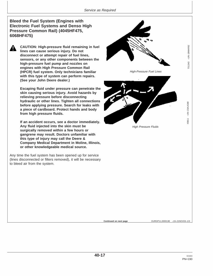
Service as Required
OURGP11,000013E –19–21NOV03–1/3
Bleed the Fuel System (Engines withElectronic Fuel Systems and Denso HighPressure Common Rail) (4045HF475,6068HF475)
TS
1343
–UN
–18M
AR
92
High-Pressure Fuel Lines
X98
11–U
N–2
3AU
G88
High Pressure Fluids
CAUTION: High-pressure fluid remaining in fuellines can cause serious injury. Do notdisconnect or attempt repair of fuel lines,sensors, or any other components between thehigh-pressure fuel pump and nozzles onengines with High Pressure Common Rail(HPCR) fuel system. Only technicians familiarwith this type of system can perform repairs.(See your John Deere dealer.)
Escaping fluid under pressure can penetrate theskin causing serious injury. Avoid hazards byrelieving pressure before disconnectinghydraulic or other lines. Tighten all connectionsbefore applying pressure. Search for leaks witha piece of cardboard. Protect hands and bodyfrom high pressure fluids.
If an accident occurs, see a doctor immediately.Any fluid injected into the skin must besurgically removed within a few hours organgrene may result. Doctors unfamiliar withthis type of injury may call the Deere &Company Medical Department in Moline, Illinois,or other knowledgeable medical source.
Any time the fuel system has been opened up for service(lines disconnected or filters removed), it will be necessaryto bleed air from the system.
Continued on next page
40-17 021604
PN=190
https://www.truck-manuals.net/
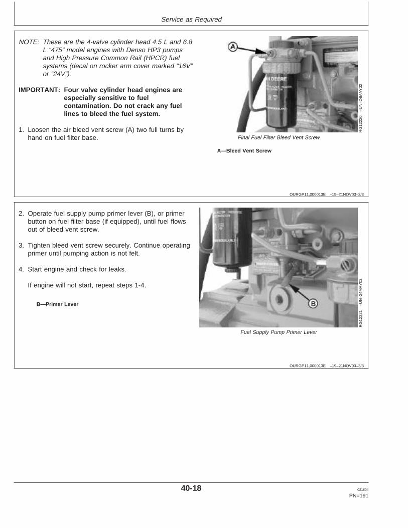
Service as Required
OURGP11,000013E –19–21NOV03–2/3
RG
1222
0–U
N–2
4MA
Y02
Final Fuel Filter Bleed Vent Screw
A—Bleed Vent Screw
NOTE: These are the 4-valve cylinder head 4.5 L and 6.8L “475” model engines with Denso HP3 pumpsand High Pressure Common Rail (HPCR) fuelsystems (decal on rocker arm cover marked “16V”or “24V”).
IMPORTANT: Four valve cylinder head engines areespecially sensitive to fuelcontamination. Do not crack any fuellines to bleed the fuel system.
1. Loosen the air bleed vent screw (A) two full turns byhand on fuel filter base.
OURGP11,000013E –19–21NOV03–3/3
RG
1222
1–U
N–2
4MA
Y02
Fuel Supply Pump Primer Lever
B—Primer Lever
2. Operate fuel supply pump primer lever (B), or primerbutton on fuel filter base (if equipped), until fuel flowsout of bleed vent screw.
3. Tighten bleed vent screw securely. Continue operatingprimer until pumping action is not felt.
4. Start engine and check for leaks.
If engine will not start, repeat steps 1-4.
40-18 021604
PN=191
https://www.truck-manuals.net/
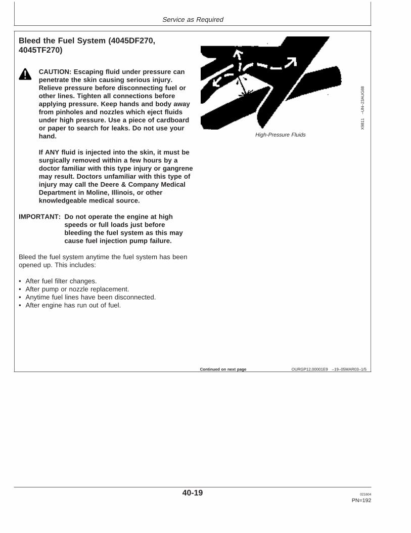
Service as Required
OURGP12,00001E9 –19–05MAR03–1/5
Bleed the Fuel System (4045DF270,4045TF270)
X98
11–U
N–2
3AU
G88
High-Pressure Fluids
CAUTION: Escaping fluid under pressure canpenetrate the skin causing serious injury.Relieve pressure before disconnecting fuel orother lines. Tighten all connections beforeapplying pressure. Keep hands and body awayfrom pinholes and nozzles which eject fluidsunder high pressure. Use a piece of cardboardor paper to search for leaks. Do not use yourhand.
If ANY fluid is injected into the skin, it must besurgically removed within a few hours by adoctor familiar with this type injury or gangrenemay result. Doctors unfamiliar with this type ofinjury may call the Deere & Company MedicalDepartment in Moline, Illinois, or otherknowledgeable medical source.
IMPORTANT: Do not operate the engine at highspeeds or full loads just beforebleeding the fuel system as this maycause fuel injection pump failure.
Bleed the fuel system anytime the fuel system has beenopened up. This includes:
• After fuel filter changes.• After pump or nozzle replacement.• Anytime fuel lines have been disconnected.• After engine has run out of fuel.
Continued on next page
40-19 021604
PN=192
https://www.truck-manuals.net/

Service as Required
OURGP12,00001E9 –19–05MAR03–2/5
RG
7947
–UN
–13N
OV
97
Air Bleed Vent Screw
A—Vent Screw
1. Loosen the air bleed vent screw (A) two full turns byhand on fuel filter base.
OURGP12,00001E9 –19–05MAR03–3/5
RG
8013
A–U
N–1
5JA
N99
Fuel Supply Pump Primer Lever
B—Fuel Supply Pump Primer Lever
2. Operate supply pump primer lever (B) until fuel flow isfree from air bubbles.
3. Tighten bleed plug securely, continue operating handprimer until pumping action is not felt. Push handprimer inward (toward engine) as far as it will go.
4. Start engine and check for leaks.
If engine will not start, it may be necessary to bleed airfrom fuel system at fuel injection pump or injectionnozzles as explained next.
Continued on next page
40-20 021604
PN=193
https://www.truck-manuals.net/
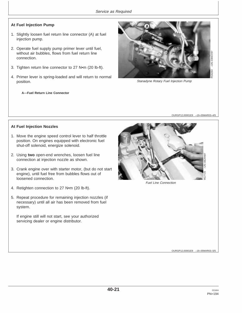
Service as Required
OURGP12,00001E9 –19–05MAR03–4/5
RG
6264
–UN
–03N
OV
97
Stanadyne Rotary Fuel Injection Pump
A—Fuel Return Line Connector
At Fuel Injection Pump
1. Slightly loosen fuel return line connector (A) at fuelinjection pump.
2. Operate fuel supply pump primer lever until fuel,without air bubbles, flows from fuel return lineconnection.
3. Tighten return line connector to 27 N•m (20 lb-ft).
4. Primer lever is spring-loaded and will return to normalposition.
OURGP12,00001E9 –19–05MAR03–5/5
RG
7725
–UN
–08J
AN
97
Fuel Line Connection
At Fuel Injection Nozzles
1. Move the engine speed control lever to half throttleposition. On engines equipped with electronic fuelshut-off solenoid, energize solenoid.
2. Using two open-end wrenches, loosen fuel lineconnection at injection nozzle as shown.
3. Crank engine over with starter motor, (but do not startengine), until fuel free from bubbles flows out ofloosened connection.
4. Retighten connection to 27 N•m (20 lb-ft).
5. Repeat procedure for remaining injection nozzles (ifnecessary) until all air has been removed from fuelsystem.
If engine still will not start, see your authorizedservicing dealer or engine distributor.
40-21 021604
PN=194
https://www.truck-manuals.net/
Troubleshooting
RG,RG34710,5605 –19–12NOV01–1/1
General Troubleshooting Information
Troubleshooting engine problems can be difficult. Anengine wiring diagram is provided in this section tohelp isolate electrical problems on power units usingJohn Deere wiring harness and instrument (gauge)panel.
Wiring diagrams are shown for the electronicinstrument panel and harness offered for theseengines.
Later in this section is a list of possible engineproblems that may be encountered accompanied bypossible causes and corrections. The illustrateddiagrams and troubleshooting information are of ageneral nature; final design of the overall system foryour engine application may be different. See yourengine distributor or servicing dealer if you are indoubt.
A reliable program for troubleshooting engine problemsshould include the following basic diagnostic thoughtprocess:
• Know the engine and all related systems.• Study the problem thoroughly.• Relate the symptoms to your knowledge of engine
and systems.• Diagnose the problem starting with the easiest
things first.• Double-check before beginning the disassembly.• Determine cause and make a thorough repair.• After making repairs, operate the engine under
normal conditions to verify that the problem andcause was corrected.
NOTE: The engines covered in this manual haveelectronic control systems which senddiagnostic trouble codes to signal problems(see DIAGNOSTIC TROUBLE CODEPROCEDURE, later in this section).
45-1 021604
PN=195
https://www.truck-manuals.net/
Troubleshooting
OUOD002,000016B –19–08OCT01–1/1
Precautions For Welding On EnginesEquipped With Electronic Engine ControlUnit (ECU)
IMPORTANT: ALWAYS disconnect Electronic ControlUnit (ECU) connectors and enginecontrol system-to-machine groundbefore welding on engine or machine.High currents or electro-staticdischarge in electronic componentsfrom welding may cause permanentdamage.
1. Remove the ground connection for the engine controlsystem-to-machine frame.
2. Disconnect the connectors from the ECU.
3. Connect the welder ground close to the welding pointand be sure ECU or other electronic components are notin the ground path.
45-2 021604
PN=196
https://www.truck-manuals.net/
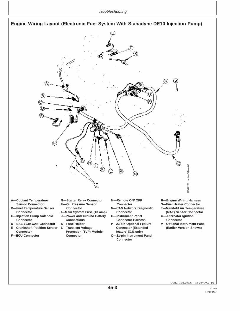
Troubleshooting
OURGP11,0000276 –19–24NOV03–1/1
Engine Wiring Layout (Electronic Fuel System With Stanadyne DE10 Injection Pump)
RG
1220
1–U
N–2
4MA
Y02
A—Coolant Temperature G—Starter Relay Connector M—Remote ON/ OFF R—Engine Wiring HarnessSensor Connector H—Oil Pressure Sensor Connector S—Fuel Heater Connector
B—Fuel Temperature Sensor Connector N—CAN Network Diagnostic T—Manifold Air TemperatureConnector I—Main System Fuse (10 amp) Connector (MAT) Sensor Connector
C—Injection Pump Solenoid J—Power and Ground Battery O—Instrument Panel U—Alternator IgnitionConnector Connections Connector Harness Connector
D—SAE 1939 CAN Connector K—Fuse Holder P—23-pin Optional Feature V—Optional Instrument PanelE—Crankshaft Position Sensor L—Transient Voltage Connector (Extended- (Earlier Version Shown)
Connector Protection (TVP) Module feature ECU only)F—ECU Connector Connector Q—21-pin Instrument Panel
Connector
45-3 021604
PN=197
https://www.truck-manuals.net/
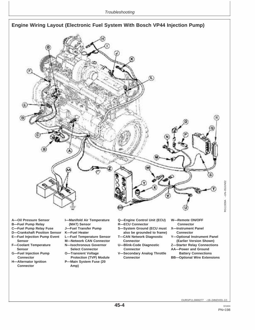
Troubleshooting
OURGP11,0000277 –19–24NOV03–1/1
Engine Wiring Layout (Electronic Fuel System With Bosch VP44 Injection Pump)
RG
1193
9A–U
N–0
5JU
N02
A—Oil Pressure Sensor I—Manifold Air Temperature Q—Engine Control Unit (ECU) W—Remote ON/OFFB—Fuel Pump Relay (MAT) Sensor R—ECU Connector ConnectorC—Fuel Pump Relay Fuse J—Fuel Transfer Pump S—System Ground (ECU must X—Instrument PanelD—Crankshaft Position Sensor K—Fuel Heater also be grounded to frame) ConnectorE—Fuel Injection Pump Event L—Fuel Temperature Sensor T—CAN Network Diagnostic Y—Optional Instrument Panel
Sensor M—Network CAN Connector Connector (Earlier Version Shown)F—Coolant Temperature N—Isochronous Governor U—Blink-Code Diagnostic Z—Starter Relay Connections
Sensor Select Connector Connector AA—Power and GroundG—Fuel Injection Pump O—Transient Voltage V—Secondary Analog Throttle Battery Connections
Connector Protection (TVP) Module Connector BB—Optional Wire ExtensionsH—Alternator Ignition P—Main System Fuse (20
Connector Amp)
45-4 021604
PN=198
https://www.truck-manuals.net/
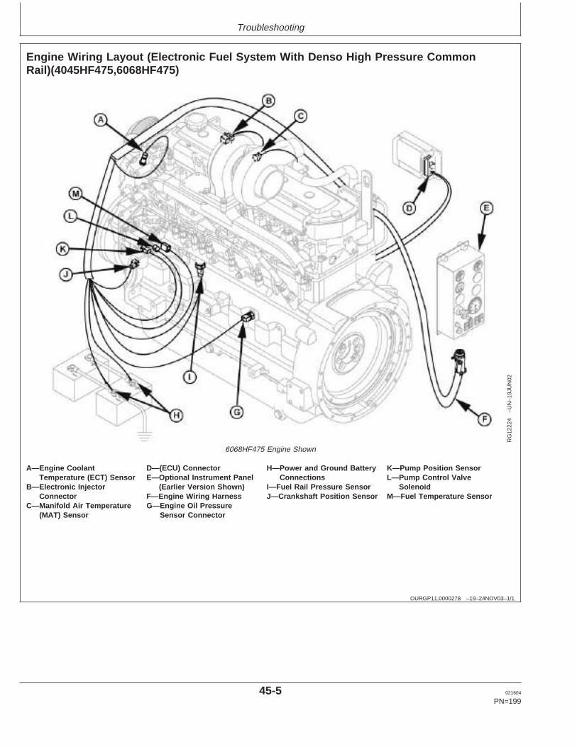
Troubleshooting
OURGP11,0000278 –19–24NOV03–1/1
Engine Wiring Layout (Electronic Fuel System With Denso High Pressure CommonRail)(4045HF475,6068HF475)
RG
1222
4–U
N–1
9JU
N02
6068HF475 Engine Shown
A—Engine Coolant D—(ECU) Connector H—Power and Ground Battery K—Pump Position SensorTemperature (ECT) Sensor E—Optional Instrument Panel Connections L—Pump Control Valve
B—Electronic Injector (Earlier Version Shown) I—Fuel Rail Pressure Sensor SolenoidConnector F—Engine Wiring Harness J—Crankshaft Position Sensor M—Fuel Temperature Sensor
C—Manifold Air Temperature G—Engine Oil Pressure(MAT) Sensor Sensor Connector
45-5 021604
PN=199
https://www.truck-manuals.net/
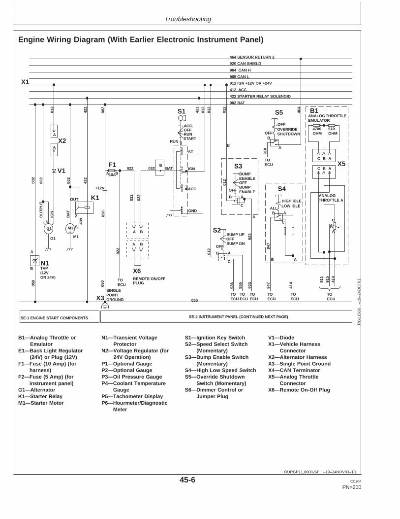
Troubleshooting
OURGP11,000026F –19–24NOV03–1/1
Engine Wiring Diagram (With Earlier Electronic Instrument Panel)
414
BATB
BA
BA
X6REMOTE ON/OFFPLUG
022
032
032022
AB
C
905 CAN L
012 IGN +12V OR +24V
412 ACC
422 STARTER RELAY SOLENOID
002 BAT
904 CAN H
020 CAN SHIELD
464 SENSOR RETURN 2
911
915
414
SE-2 INSTRUMENT PANEL (CONTINUED NEXT PAGE)SE-1 ENGINE START COMPONENTS
923
OFFOVERRIDESHUTDOWN
BOFF
A
918
S5 464
TOECU
HIGH IDLELOW IDLE
BALL
A
C
TOECU
TOECU
947
S4
947
B A
TOECU
TOECU
BUMP UPOFFBUMP DN
OFF
AB
C
BUMPENABLE
BUMPENABLEOFF
OFF
AB
C01
2
012
012
S1
OFFRUNSTART
RUN
ST
IGN
ACC
GND
422
012
ACC.
422
002
A
B TVP(12V OR 24V)
002
050
012
IG
N
OU
TP
UT
N1
V1
G1 M1
050
TOECU
012
SINGLEPOINT GROUND
F110A
G1 M1
K1
B
OUT
2
X3
X2
S2
S3
A
B
A
002
X1
923
955
936
422
022
050
050
+12V
002
A
A
TOECU
S
BAT
S 409
X5ABC
AC B
B1ANALOG THROTTLEEMULATOR
4700 OHM
510OHM
ANALOGTHROTTLE A
TOECU
RG
1156
8–1
9–24
OC
T01
B1—Analog Throttle or N1—Transient Voltage S1—Ignition Key Switch V1—DiodeEmulator Protector S2—Speed Select Switch X1—Vehicle Harness
E1—Back Light Regulator N2—Voltage Regulator (for (Momentary) Connector(24V) or Plug (12V) 24V Operation) S3—Bump Enable Switch X2—Alternator Harness
F1—Fuse (10 Amp) (for P1—Optional Gauge (Momentary) X3—Single Point Groundharness) P2—Optional Gauge S4—High Low Speed Switch X4—CAN Terminator
F2—Fuse (5 Amp) (for P3—Oil Pressure Gauge S5—Override Shutdown X5—Analog Throttleinstrument panel) P4—Coolant Temperature Switch (Momentary) Connector
G1—Alternator Gauge S6—Dimmer Control or X6—Remote On-Off PlugK1—Starter Relay P5—Tachometer Display Jumper PlugM1—Starter Motor P6—Hourmeter/Diagnostic
Meter
45-6 021604
PN=200
https://www.truck-manuals.net/
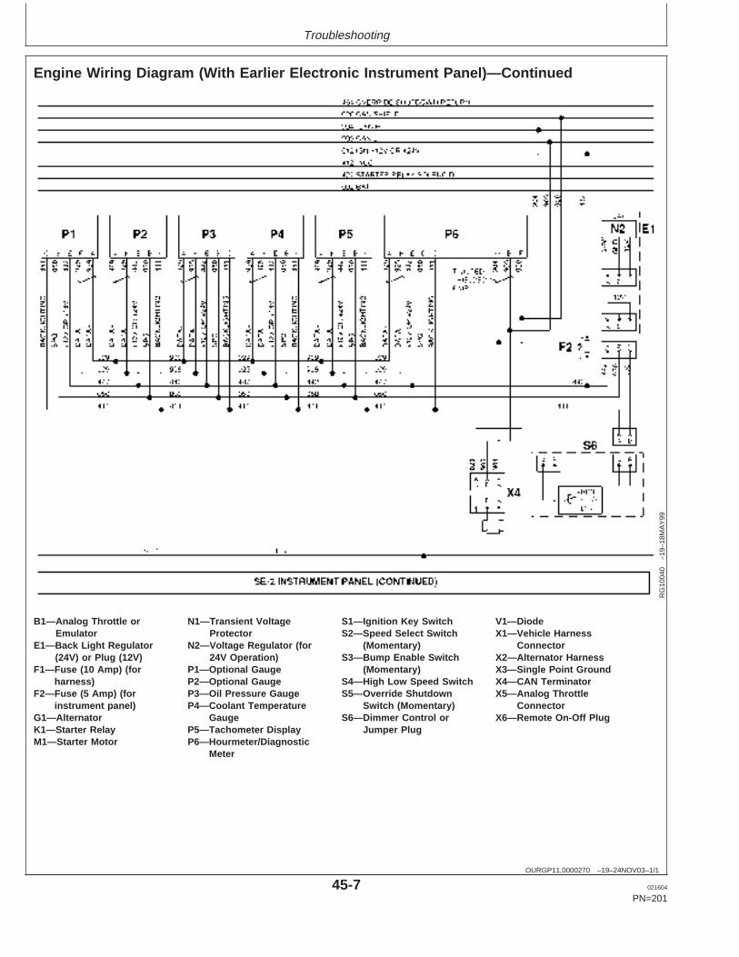
Troubleshooting
OURGP11,0000270 –19–24NOV03–1/1
Engine Wiring Diagram (With Earlier Electronic Instrument Panel)—Continued
RG
1004
0–1
9–18
MA
Y99
B1—Analog Throttle or N1—Transient Voltage S1—Ignition Key Switch V1—DiodeEmulator Protector S2—Speed Select Switch X1—Vehicle Harness
E1—Back Light Regulator N2—Voltage Regulator (for (Momentary) Connector(24V) or Plug (12V) 24V Operation) S3—Bump Enable Switch X2—Alternator Harness
F1—Fuse (10 Amp) (for P1—Optional Gauge (Momentary) X3—Single Point Groundharness) P2—Optional Gauge S4—High Low Speed Switch X4—CAN Terminator
F2—Fuse (5 Amp) (for P3—Oil Pressure Gauge S5—Override Shutdown X5—Analog Throttleinstrument panel) P4—Coolant Temperature Switch (Momentary) Connector
G1—Alternator Gauge S6—Dimmer Control or X6—Remote On-Off PlugK1—Starter Relay P5—Tachometer Display Jumper PlugM1—Starter Motor P6—Hourmeter/Diagnostic
Meter
45-7 021604
PN=201
https://www.truck-manuals.net/
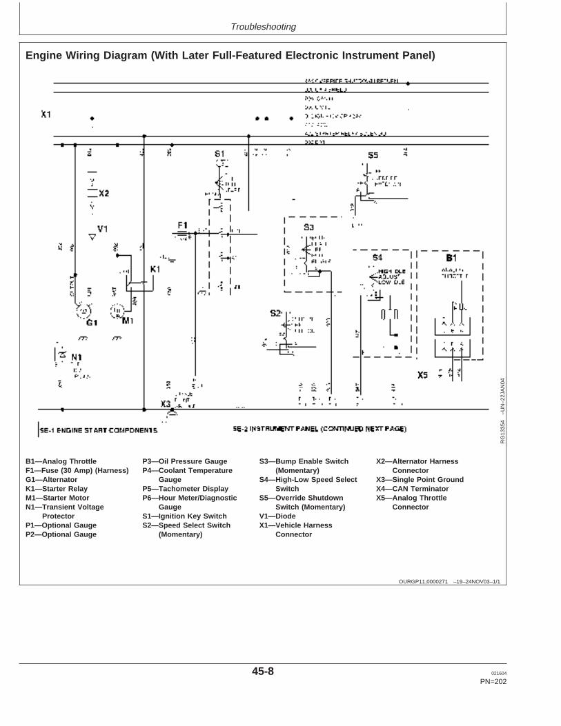
Troubleshooting
OURGP11,0000271 –19–24NOV03–1/1
Engine Wiring Diagram (With Later Full-Featured Electronic Instrument Panel)
RG
1335
4–U
N–2
2JA
N04
B1—Analog Throttle P3—Oil Pressure Gauge S3—Bump Enable Switch X2—Alternator HarnessF1—Fuse (30 Amp) (Harness) P4—Coolant Temperature (Momentary) ConnectorG1—Alternator Gauge S4—High-Low Speed Select X3—Single Point GroundK1—Starter Relay P5—Tachometer Display Switch X4—CAN TerminatorM1—Starter Motor P6—Hour Meter/Diagnostic S5—Override Shutdown X5—Analog ThrottleN1—Transient Voltage Gauge Switch (Momentary) Connector
Protector S1—Ignition Key Switch V1—DiodeP1—Optional Gauge S2—Speed Select Switch X1—Vehicle HarnessP2—Optional Gauge (Momentary) Connector
45-8 021604
PN=202
https://www.truck-manuals.net/
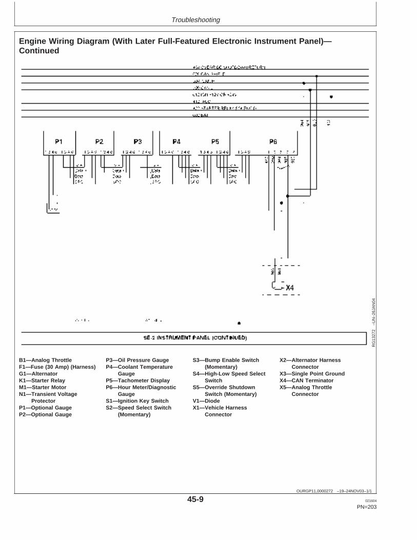
Troubleshooting
OURGP11,0000272 –19–24NOV03–1/1
Engine Wiring Diagram (With Later Full-Featured Electronic Instrument Panel)—Continued
RG
1327
2–U
N–2
6JA
N04
B1—Analog Throttle P3—Oil Pressure Gauge S3—Bump Enable Switch X2—Alternator HarnessF1—Fuse (30 Amp) (Harness) P4—Coolant Temperature (Momentary) ConnectorG1—Alternator Gauge S4—High-Low Speed Select X3—Single Point GroundK1—Starter Relay P5—Tachometer Display Switch X4—CAN TerminatorM1—Starter Motor P6—Hour Meter/Diagnostic S5—Override Shutdown X5—Analog ThrottleN1—Transient Voltage Gauge Switch (Momentary) Connector
Protector S1—Ignition Key Switch V1—DiodeP1—Optional Gauge S2—Speed Select Switch X1—Vehicle HarnessP2—Optional Gauge (Momentary) Connector
45-9 021604
PN=203
https://www.truck-manuals.net/
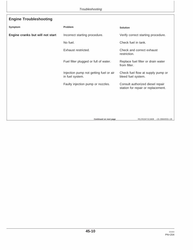
Troubleshooting
RG,RG34710,5608 –19–28MAR03–1/8
Engine Troubleshooting
Symptom Problem Solution
Engine cranks but will not start Incorrect starting procedure. Verify correct starting procedure.
No fuel. Check fuel in tank.
Exhaust restricted. Check and correct exhaustrestriction.
Fuel filter plugged or full of water. Replace fuel filter or drain waterfrom filter.
Injection pump not getting fuel or air Check fuel flow at supply pump orin fuel system. bleed fuel system.
Faulty injection pump or nozzles. Consult authorized diesel repairstation for repair or replacement.
Continued on next page
45-10 021604
PN=204
https://www.truck-manuals.net/
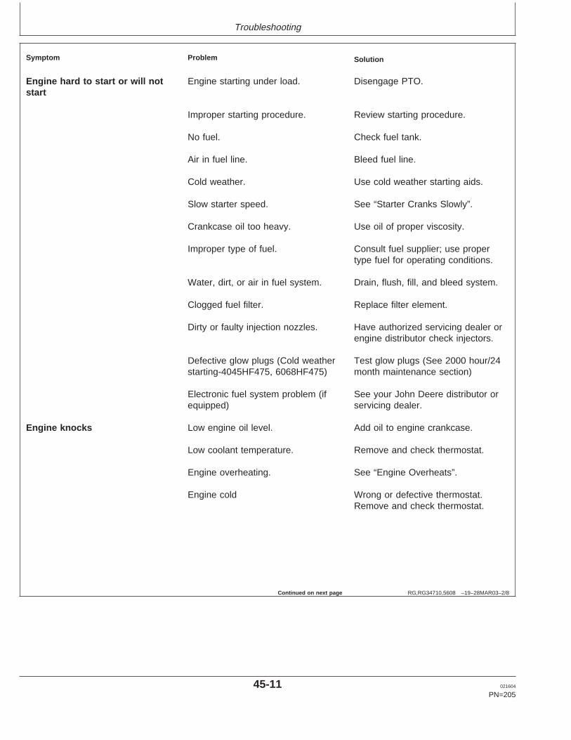
Troubleshooting
RG,RG34710,5608 –19–28MAR03–2/8
Symptom Problem Solution
Engine hard to start or will not Engine starting under load. Disengage PTO.start
Improper starting procedure. Review starting procedure.
No fuel. Check fuel tank.
Air in fuel line. Bleed fuel line.
Cold weather. Use cold weather starting aids.
Slow starter speed. See “Starter Cranks Slowly”.
Crankcase oil too heavy. Use oil of proper viscosity.
Improper type of fuel. Consult fuel supplier; use propertype fuel for operating conditions.
Water, dirt, or air in fuel system. Drain, flush, fill, and bleed system.
Clogged fuel filter. Replace filter element.
Dirty or faulty injection nozzles. Have authorized servicing dealer orengine distributor check injectors.
Defective glow plugs (Cold weather Test glow plugs (See 2000 hour/24starting-4045HF475, 6068HF475) month maintenance section)
Electronic fuel system problem (if See your John Deere distributor orequipped) servicing dealer.
Engine knocks Low engine oil level. Add oil to engine crankcase.
Low coolant temperature. Remove and check thermostat.
Engine overheating. See “Engine Overheats”.
Engine cold Wrong or defective thermostat.Remove and check thermostat.
Continued on next page
45-11 021604
PN=205
https://www.truck-manuals.net/
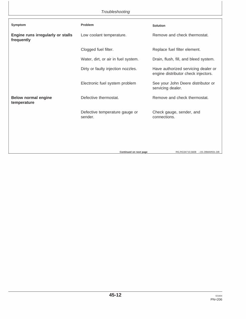
Troubleshooting
RG,RG34710,5608 –19–28MAR03–3/8
Symptom Problem Solution
Engine runs irregularly or stalls Low coolant temperature. Remove and check thermostat.frequently
Clogged fuel filter. Replace fuel filter element.
Water, dirt, or air in fuel system. Drain, flush, fill, and bleed system.
Dirty or faulty injection nozzles. Have authorized servicing dealer orengine distributor check injectors.
Electronic fuel system problem See your John Deere distributor orservicing dealer.
Below normal engine Defective thermostat. Remove and check thermostat.temperature
Defective temperature gauge or Check gauge, sender, andsender. connections.
Continued on next page
45-12 021604
PN=206
https://www.truck-manuals.net/
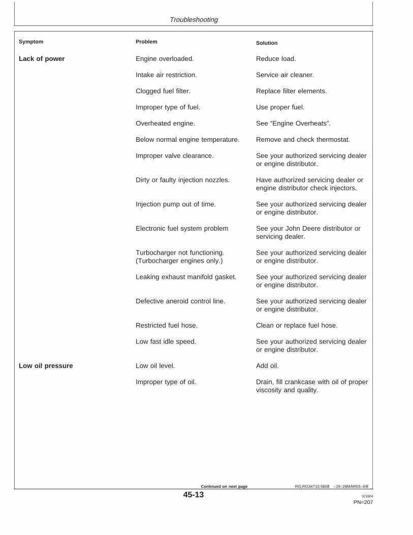
Troubleshooting
RG,RG34710,5608 –19–28MAR03–4/8
Symptom Problem Solution
Lack of power Engine overloaded. Reduce load.
Intake air restriction. Service air cleaner.
Clogged fuel filter. Replace filter elements.
Improper type of fuel. Use proper fuel.
Overheated engine. See “Engine Overheats”.
Below normal engine temperature. Remove and check thermostat.
Improper valve clearance. See your authorized servicing dealeror engine distributor.
Dirty or faulty injection nozzles. Have authorized servicing dealer orengine distributor check injectors.
Injection pump out of time. See your authorized servicing dealeror engine distributor.
Electronic fuel system problem See your John Deere distributor orservicing dealer.
Turbocharger not functioning. See your authorized servicing dealer(Turbocharger engines only.) or engine distributor.
Leaking exhaust manifold gasket. See your authorized servicing dealeror engine distributor.
Defective aneroid control line. See your authorized servicing dealeror engine distributor.
Restricted fuel hose. Clean or replace fuel hose.
Low fast idle speed. See your authorized servicing dealeror engine distributor.
Low oil pressure Low oil level. Add oil.
Improper type of oil. Drain, fill crankcase with oil of properviscosity and quality.
45-13 021604
PN=207
Continued on next page
https://www.truck-manuals.net/
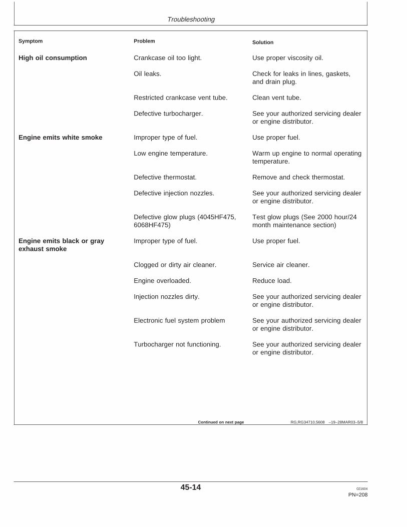
Troubleshooting
RG,RG34710,5608 –19–28MAR03–5/8
Symptom Problem Solution
High oil consumption Crankcase oil too light. Use proper viscosity oil.
Oil leaks. Check for leaks in lines, gaskets,and drain plug.
Restricted crankcase vent tube. Clean vent tube.
Defective turbocharger. See your authorized servicing dealeror engine distributor.
Engine emits white smoke Improper type of fuel. Use proper fuel.
Low engine temperature. Warm up engine to normal operatingtemperature.
Defective thermostat. Remove and check thermostat.
Defective injection nozzles. See your authorized servicing dealeror engine distributor.
Defective glow plugs (4045HF475, Test glow plugs (See 2000 hour/246068HF475) month maintenance section)
Engine emits black or gray Improper type of fuel. Use proper fuel.exhaust smoke
Clogged or dirty air cleaner. Service air cleaner.
Engine overloaded. Reduce load.
Injection nozzles dirty. See your authorized servicing dealeror engine distributor.
Electronic fuel system problem See your authorized servicing dealeror engine distributor.
Turbocharger not functioning. See your authorized servicing dealeror engine distributor.
Continued on next page
45-14 021604
PN=208
https://www.truck-manuals.net/
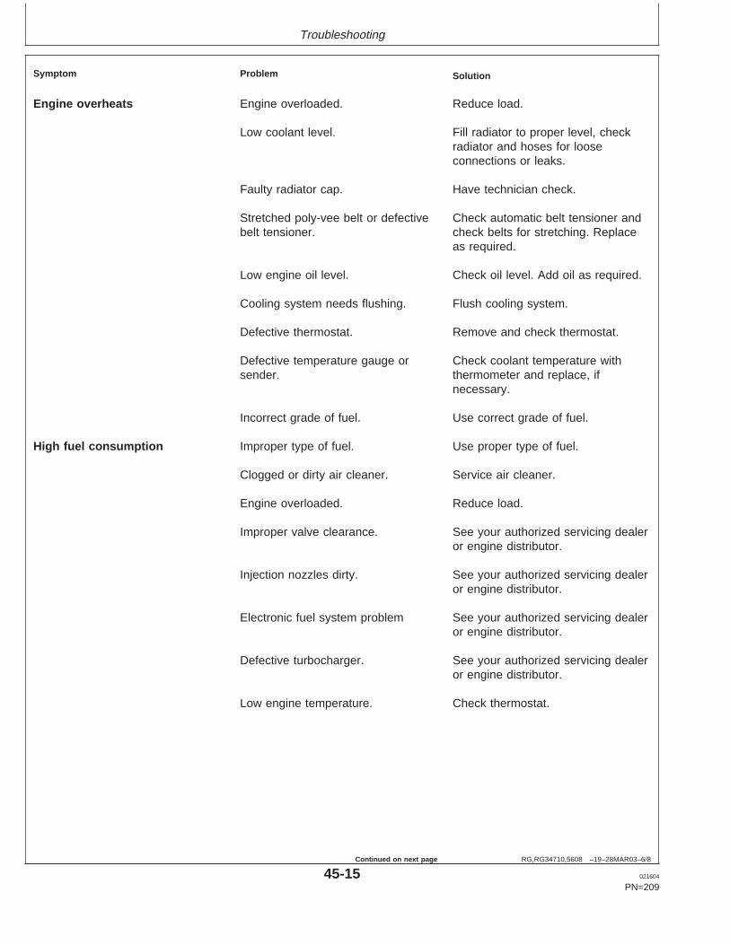
Troubleshooting
RG,RG34710,5608 –19–28MAR03–6/8
Symptom Problem Solution
Engine overheats Engine overloaded. Reduce load.
Low coolant level. Fill radiator to proper level, checkradiator and hoses for looseconnections or leaks.
Faulty radiator cap. Have technician check.
Stretched poly-vee belt or defective Check automatic belt tensioner andbelt tensioner. check belts for stretching. Replace
as required.
Low engine oil level. Check oil level. Add oil as required.
Cooling system needs flushing. Flush cooling system.
Defective thermostat. Remove and check thermostat.
Defective temperature gauge or Check coolant temperature withsender. thermometer and replace, if
necessary.
Incorrect grade of fuel. Use correct grade of fuel.
High fuel consumption Improper type of fuel. Use proper type of fuel.
Clogged or dirty air cleaner. Service air cleaner.
Engine overloaded. Reduce load.
Improper valve clearance. See your authorized servicing dealeror engine distributor.
Injection nozzles dirty. See your authorized servicing dealeror engine distributor.
Electronic fuel system problem See your authorized servicing dealeror engine distributor.
Defective turbocharger. See your authorized servicing dealeror engine distributor.
Low engine temperature. Check thermostat.
45-15 021604
PN=209
Continued on next page
https://www.truck-manuals.net/
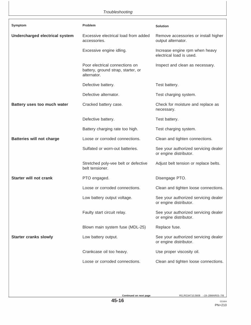
Troubleshooting
RG,RG34710,5608 –19–28MAR03–7/8
Symptom Problem Solution
Undercharged electrical system Excessive electrical load from added Remove accessories or install higheraccessories. output alternator.
Excessive engine idling. Increase engine rpm when heavyelectrical load is used.
Poor electrical connections on Inspect and clean as necessary.battery, ground strap, starter, oralternator.
Defective battery. Test battery.
Defective alternator. Test charging system.
Battery uses too much water Cracked battery case. Check for moisture and replace asnecessary.
Defective battery. Test battery.
Battery charging rate too high. Test charging system.
Batteries will not charge Loose or corroded connections. Clean and tighten connections.
Sulfated or worn-out batteries. See your authorized servicing dealeror engine distributor.
Stretched poly-vee belt or defective Adjust belt tension or replace belts.belt tensioner.
Starter will not crank PTO engaged. Disengage PTO.
Loose or corroded connections. Clean and tighten loose connections.
Low battery output voltage. See your authorized servicing dealeror engine distributor.
Faulty start circuit relay. See your authorized servicing dealeror engine distributor.
Blown main system fuse (MDL-25) Replace fuse.
Starter cranks slowly Low battery output. See your authorized servicing dealeror engine distributor.
Crankcase oil too heavy. Use proper viscosity oil.
Loose or corroded connections. Clean and tighten loose connections.
45-16 021604
PN=210
Continued on next page
https://www.truck-manuals.net/
Troubleshooting
RG,RG34710,5608 –19–28MAR03–8/8
Symptom Problem Solution
Starter and hour meter functions; Blown fuse on magnetic switch. Replace fuse.rest of electrical system does notfunction
Entire electrical system does not Faulty battery connection. Clean and tighten connections.function
Sulfated or worn-out batteries. See your authorized servicing dealeror engine distributor.
Blown main system fuse. Replace fuse.
45-17 021604
PN=211
https://www.truck-manuals.net/
Troubleshooting
OURGP12,00001EB –19–11MAR03–1/2
Blink Code Method for Retrieving DiagnosticTrouble Codes (All Except Early VP44 PumpEngines)
NOTE: If engine has an electronic instrument panel withdiagnostic gauge, refer to “Instrument PanelMethod for Retrieving Diagnostic Trouble Codes”later in this section.
On OEM applications that have a Fault Lamp, the ECUhas the ability to display DTCs using blinking sequence ofthe fault lamp. To retrieve DTCs from the ECU using the“blink code” method:
NOTE: The ECU blinks the codes in 2-digit codes only.See LISTING OF DIAGNOSTIC TROUBLECODES (DTCS) later in this Group.
1. Turn the ignition switch “ON”.
2. Press down Override Shutdown Switch (if equipped)for a few seconds.
3. The Fault Lamp will begin to flash a code number. Forexample, flash three times...short pause...flash twotimes...long pause. This example is code 32.
4. The ECU begins the flashing sequence by flashing acode 32, this indicates the start of blinking activecodes. If there are any active DTCs, the ECU will flashit’s 2–digit number. If there is more than one activeDTC, the ECU will flash each code in numerical order.If there are no active DTCs, the Fault Lamp will flash acode 88.
5. Following the active codes, the Fault Lamp will flash acode 33. This indicates the start of blinking storedcodes. If there are any stored DTCs, the Fault Lampwill flash its 2–digit number. If there is more than onestored DTC, the ECU will flash each code in numericalorder. If there are no stored DTCs, the Fault Lamp willflash a code 88.
6. Once complete, this sequence will repeat.
7. When complete, turn ignition “OFF”.
45-18 021604
PN=212
Continued on next page
https://www.truck-manuals.net/
Troubleshooting
OURGP12,00001EB –19–11MAR03–2/2
As an example, if an engine had an active DTC 18 andstored DTC 53, the flashing sequence would be: flashthree times...short pause...flash two times...longpause...flash one time...short pause...flash eighttimes...long pause...flash three times...short pause...flashthree times...long pause...flash five times...shortpause...flash three times.
45-19 021604
PN=213
https://www.truck-manuals.net/
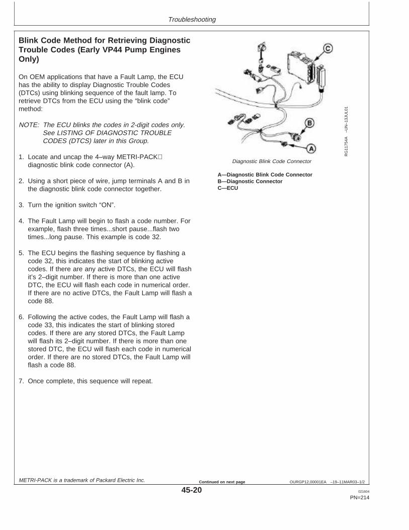
Troubleshooting
OURGP12,00001EA –19–11MAR03–1/2
Blink Code Method for Retrieving DiagnosticTrouble Codes (Early VP44 Pump EnginesOnly)
RG
1175
4A–U
N–1
3JU
L01
Diagnostic Blink Code Connector
A—Diagnostic Blink Code ConnectorB—Diagnostic ConnectorC—ECU
On OEM applications that have a Fault Lamp, the ECUhas the ability to display Diagnostic Trouble Codes(DTCs) using blinking sequence of the fault lamp. Toretrieve DTCs from the ECU using the “blink code”method:
NOTE: The ECU blinks the codes in 2-digit codes only.See LISTING OF DIAGNOSTIC TROUBLECODES (DTCS) later in this Group.
1. Locate and uncap the 4–way METRI-PACKdiagnostic blink code connector (A).
2. Using a short piece of wire, jump terminals A and B inthe diagnostic blink code connector together.
3. Turn the ignition switch “ON”.
4. The Fault Lamp will begin to flash a code number. Forexample, flash three times...short pause...flash twotimes...long pause. This example is code 32.
5. The ECU begins the flashing sequence by flashing acode 32, this indicates the start of blinking activecodes. If there are any active DTCs, the ECU will flashit’s 2–digit number. If there is more than one activeDTC, the ECU will flash each code in numerical order.If there are no active DTCs, the Fault Lamp will flash acode 88.
6. Following the active codes, the Fault Lamp will flash acode 33, this indicates the start of blinking storedcodes. If there are any stored DTCs, the Fault Lampwill flash its 2–digit number. If there is more than onestored DTC, the ECU will flash each code in numericalorder. If there are no stored DTCs, the Fault Lamp willflash a code 88.
7. Once complete, this sequence will repeat.
METRI-PACK is a trademark of Packard Electric Inc.
45-20 021604
PN=214
Continued on next page
https://www.truck-manuals.net/
Troubleshooting
OURGP12,00001EA –19–11MAR03–2/2
8. When complete, turn ignition “OFF”, remove jumperwire, and recap the diagnostic reader connector.
As an example, if an engine had an active DTC 18 andstored DTC 53, the flashing sequence would be: flashthree times...short pause...flash two times...longpause...flash one time...short pause...flash eighttimes...long pause...flash three times...short pause...flashthree times...long pause...flash five times...shortpause...flash three times.
45-21 021604
PN=215
https://www.truck-manuals.net/
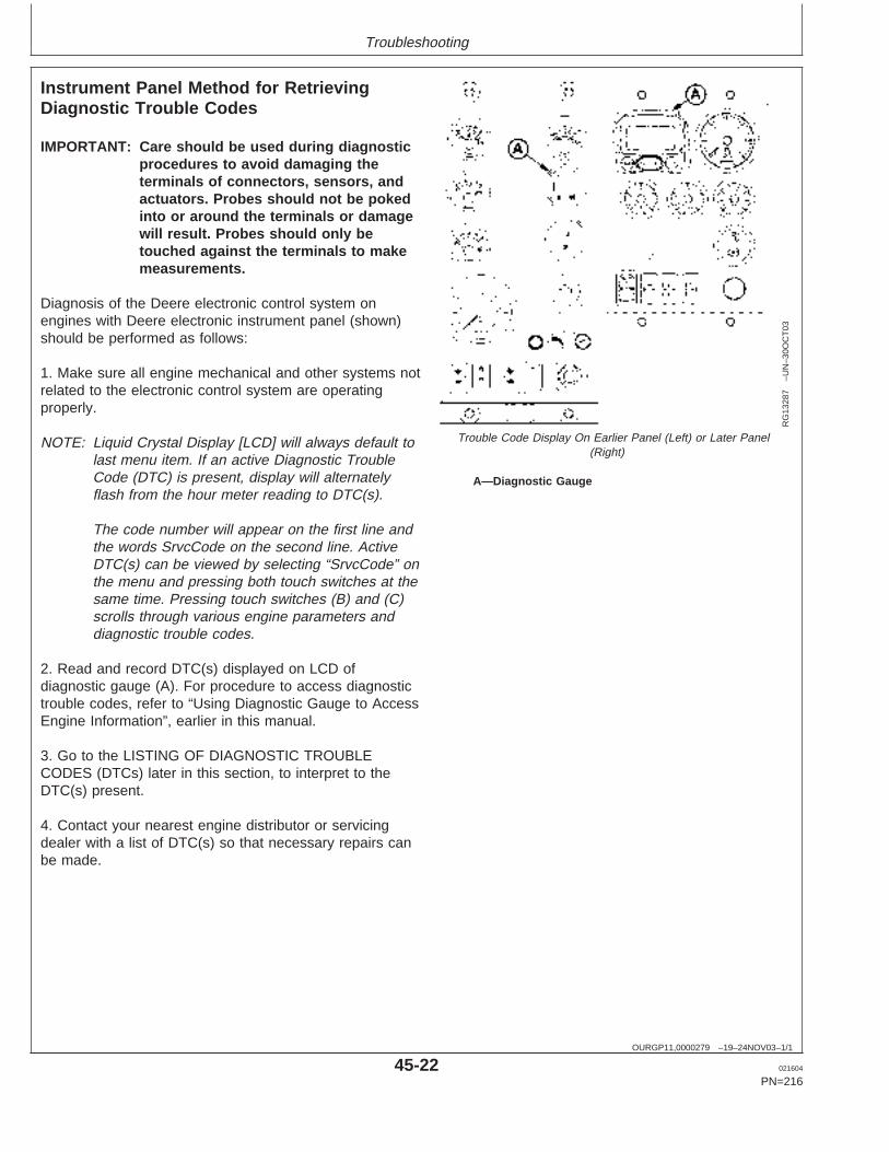
Troubleshooting
OURGP11,0000279 –19–24NOV03–1/1
Instrument Panel Method for RetrievingDiagnostic Trouble Codes
RG
1328
7–U
N–3
0OC
T03
Trouble Code Display On Earlier Panel (Left) or Later Panel(Right)
A—Diagnostic Gauge
IMPORTANT: Care should be used during diagnosticprocedures to avoid damaging theterminals of connectors, sensors, andactuators. Probes should not be pokedinto or around the terminals or damagewill result. Probes should only betouched against the terminals to makemeasurements.
Diagnosis of the Deere electronic control system onengines with Deere electronic instrument panel (shown)should be performed as follows:
1. Make sure all engine mechanical and other systems notrelated to the electronic control system are operatingproperly.
NOTE: Liquid Crystal Display [LCD] will always default tolast menu item. If an active Diagnostic TroubleCode (DTC) is present, display will alternatelyflash from the hour meter reading to DTC(s).
The code number will appear on the first line andthe words SrvcCode on the second line. ActiveDTC(s) can be viewed by selecting “SrvcCode” onthe menu and pressing both touch switches at thesame time. Pressing touch switches (B) and (C)scrolls through various engine parameters anddiagnostic trouble codes.
2. Read and record DTC(s) displayed on LCD ofdiagnostic gauge (A). For procedure to access diagnostictrouble codes, refer to “Using Diagnostic Gauge to AccessEngine Information”, earlier in this manual.
3. Go to the LISTING OF DIAGNOSTIC TROUBLECODES (DTCs) later in this section, to interpret to theDTC(s) present.
4. Contact your nearest engine distributor or servicingdealer with a list of DTC(s) so that necessary repairs canbe made.
45-22 021604
PN=216
https://www.truck-manuals.net/
Troubleshooting
DPSG,OUOD002,1591 –19–25FEB03–1/1
Displaying Of Diagnostic Trouble Codes(DTCs)
There are several different methods for displaying bothstored and active DTCs from the ECU via a fault lamp ora diagnostic gauge on the electronic instrument panel.
2-DIGIT CODES
Some engines display Service Codes or DTCs as 2-digitcodes read from a fault lamp which gives blink codes.
SPN/FMI CODES
Stored and active diagnostic trouble codes are output onthe diagnostic gauge on the Deere electronic instrumentpanel according to the J1939 standard as a two-part codeas shown on the tables on the following pages.
The first part is a six-digit Suspect Parameter Number(SPN) followed by a two-digit Failure Mode Identifier (FMI)code. In order to determine the exact failure, both parts(SPN and FMI) of the code are needed.
The SPN identifies the system or the component that hasthe failure; for example SPN 000110 indicates a failure inthe engine coolant temperature circuit.
The FMI identifies the type of failure that has occurred; forexample FMI 03 indicates value above normal. CombiningSPN 000110 with FMI 03 yields engine coolanttemperature input voltage too high, or the equivalent of2-digit fault code 18.
If diagnosing an application that shows DTCs as SPNsand FMIs, using the following list, determine theequivalent 2-digit code and have your dealer use thediagnostic procedure in the component technical manualfor that 2-digit code.
Always contact your servicing dealer for help in correctingdiagnostic trouble codes which are displayed for yourengine.
45-23 021604
PN=217
https://www.truck-manuals.net/

Troubleshooting
OURGP11,000013F –19–21NOV03–1/2
Listing of Diagnostic Trouble Codes (DTCs)(Engines With Electronic Fuel Systems AndStanadyne DE10 Pump)
NOTE: Not all of these codes are used on all OEMengine applications.
Third column below is for Blink Code retrievalmethod only.
Trouble Codes
DTC’s Listing in Ascending SPN/FMI CodesSPN FMI Blink Codes Definition
000028 03 13 Throttle Voltage High04 14 Throttle Voltage Low
000029 03 15 Throttle Voltage High04 16 Throttle Voltage Low14 — Throttle Voltage Out of Range
000084 31 — Vehicle Speed Mismatch000091 03 11 Throttle Voltage High
04 12 Throttle Voltage Low07 — Throttle Calibration Invalid10 — Throttle Voltage Low13 — Throttle Calibration Invalid14 — Throttle Voltage Out of Range
000097 03 — Water in Fuel Input Voltage High04 — Water in Fuel Input Voltage Low16 — Water in Fuel Detected
000100 01 65 Engine Oil Pressure Extremely Low03 23 Engine Oil Pressure Input Voltage High04 24 Engine Oil Pressure Input Voltage Low18 64 Engine Oil Pressure Moderately Low
000105 03 25 Manifold Air Temperature Input Voltage High04 26 Manifold Air Temperature Input Voltage Low16 66 Manifold Air Temperature Moderately High
000110 00 69 Engine Coolant Temperature High Most Severe03 18 Engine Coolant Temperature Input Voltage High04 19 Engine Coolant Temperature Input Voltage Low15 62 Engine Coolant Temperature High Least Severe16 63 Engine Coolant Temperature High Moderately Severe
000111 00 — Loss of Coolant Temperature Extremely High03 — Loss of Coolant Temperature Input Voltage High04 — Loss of Coolant Temperature Input Voltage Low
000158 17 54 ECU Power Down Error000160 02 — Wheel Speed Input Noise000174 03 37 Fuel Temperature Input Voltage High
04 38 Fuel Temperature Input Voltage Low16 81 Fuel Temperature Moderately High
000189 00 — Engine Speed Derate000190 00 42 Engine Overspeed Extreme
16 42 Engine Overspeed Moderate000620 03 21 Sensor Supply Voltage High
45-24 021604
PN=218
Continued on next page
https://www.truck-manuals.net/
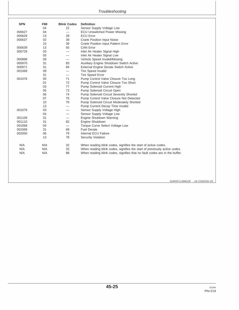
Troubleshooting
OURGP11,000013F –19–21NOV03–2/2
SPN FMI Blink Codes Definition04 22 Sensor Supply Voltage Low
000627 04 — ECU Unswitched Power Missing000629 13 28 ECU Error000637 02 39 Crank Position Input Noise
10 39 Crank Position Input Pattern Error000639 13 55 CAN Error000729 03 — Inlet Air Heater Signal High
05 — Inlet Air Heater Signal Low000898 09 — Vehicle Speed Invalid/Missing000970 31 83 Auxiliary Engine Shutdown Switch Active000971 31 84 External Engine Derate Switch Active001069 09 — Tire Speed Invalid
31 — Tire Speed Error001076 00 71 Pump Control Valve Closure Too Long
01 72 Pump Control Valve Closure Too Short03 77 Pump Solenoid Current High05 73 Pump Solenoid Circuit Open06 74 Pump Solenoid Circuit Severely Shorted07 75 Pump Control Valve Closure Not Detected10 76 Pump Solenoid Circuit Moderately Shorted13 — Pump Current Decay Time Invalid
001079 03 — Sensor Supply Voltage High04 — Sensor Supply Voltage Low
001109 31 — Engine Shutdown Warning001110 31 82 Engine Shutdown001568 04 — Torque Curve Select Voltage Low001569 31 68 Fuel Derate002000 06 79 Internal ECU Failure
13 78 Security Violation
N/A N/A 32 When reading blink codes, signifies the start of active codes.N/A N/A 33 When reading blink codes, signifies the start of previously active codes.N/A N/A 88 When reading blink codes, signifies that no fault codes are in the buffer.
45-25 021604
PN=219
https://www.truck-manuals.net/
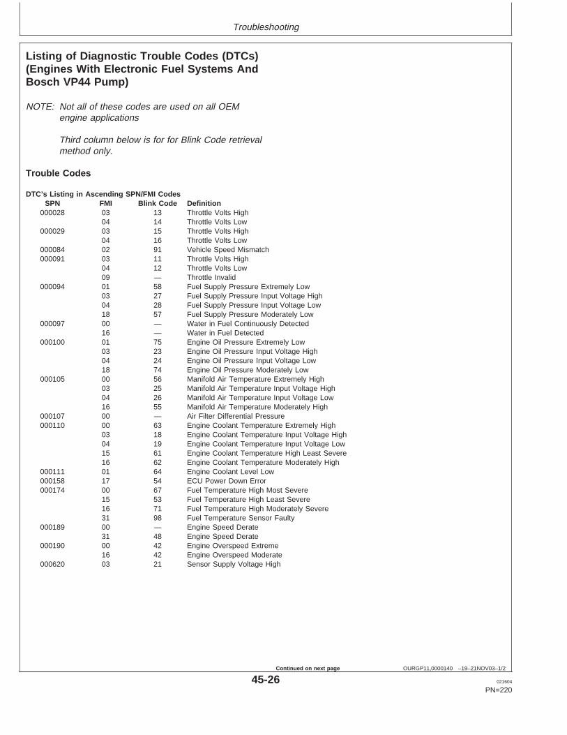
Troubleshooting
OURGP11,0000140 –19–21NOV03–1/2
Listing of Diagnostic Trouble Codes (DTCs)(Engines With Electronic Fuel Systems AndBosch VP44 Pump)
NOTE: Not all of these codes are used on all OEMengine applications
Third column below is for for Blink Code retrievalmethod only.
Trouble Codes
DTC’s Listing in Ascending SPN/FMI CodesSPN FMI Blink Code Definition
000028 03 13 Throttle Volts High04 14 Throttle Volts Low
000029 03 15 Throttle Volts High04 16 Throttle Volts Low
000084 02 91 Vehicle Speed Mismatch000091 03 11 Throttle Volts High
04 12 Throttle Volts Low09 — Throttle Invalid
000094 01 58 Fuel Supply Pressure Extremely Low03 27 Fuel Supply Pressure Input Voltage High04 28 Fuel Supply Pressure Input Voltage Low18 57 Fuel Supply Pressure Moderately Low
000097 00 — Water in Fuel Continuously Detected16 — Water in Fuel Detected
000100 01 75 Engine Oil Pressure Extremely Low03 23 Engine Oil Pressure Input Voltage High04 24 Engine Oil Pressure Input Voltage Low18 74 Engine Oil Pressure Moderately Low
000105 00 56 Manifold Air Temperature Extremely High03 25 Manifold Air Temperature Input Voltage High04 26 Manifold Air Temperature Input Voltage Low16 55 Manifold Air Temperature Moderately High
000107 00 — Air Filter Differential Pressure000110 00 63 Engine Coolant Temperature Extremely High
03 18 Engine Coolant Temperature Input Voltage High04 19 Engine Coolant Temperature Input Voltage Low15 61 Engine Coolant Temperature High Least Severe16 62 Engine Coolant Temperature Moderately High
000111 01 64 Engine Coolant Level Low000158 17 54 ECU Power Down Error000174 00 67 Fuel Temperature High Most Severe
15 53 Fuel Temperature High Least Severe16 71 Fuel Temperature High Moderately Severe31 98 Fuel Temperature Sensor Faulty
000189 00 — Engine Speed Derate31 48 Engine Speed Derate
000190 00 42 Engine Overspeed Extreme16 42 Engine Overspeed Moderate
000620 03 21 Sensor Supply Voltage High
45-26 021604
PN=220
Continued on next page
https://www.truck-manuals.net/
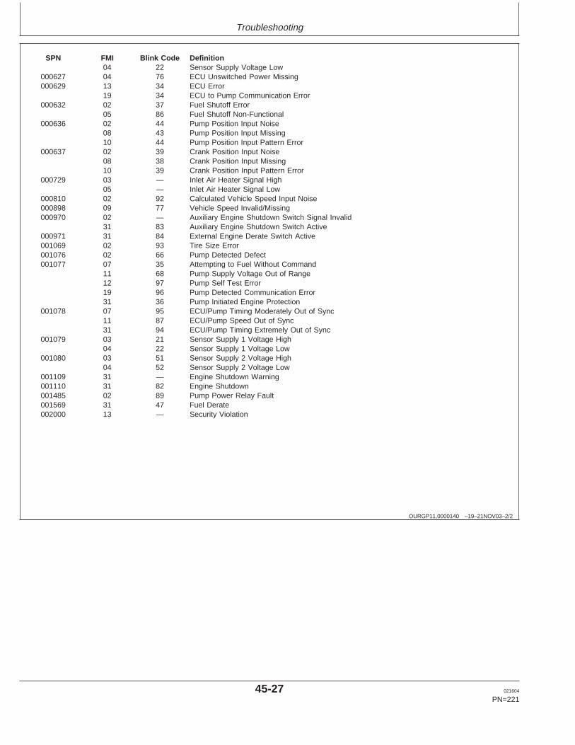
Troubleshooting
OURGP11,0000140 –19–21NOV03–2/2
SPN FMI Blink Code Definition04 22 Sensor Supply Voltage Low
000627 04 76 ECU Unswitched Power Missing000629 13 34 ECU Error
19 34 ECU to Pump Communication Error000632 02 37 Fuel Shutoff Error
05 86 Fuel Shutoff Non-Functional000636 02 44 Pump Position Input Noise
08 43 Pump Position Input Missing10 44 Pump Position Input Pattern Error
000637 02 39 Crank Position Input Noise08 38 Crank Position Input Missing10 39 Crank Position Input Pattern Error
000729 03 — Inlet Air Heater Signal High05 — Inlet Air Heater Signal Low
000810 02 92 Calculated Vehicle Speed Input Noise000898 09 77 Vehicle Speed Invalid/Missing000970 02 — Auxiliary Engine Shutdown Switch Signal Invalid
31 83 Auxiliary Engine Shutdown Switch Active000971 31 84 External Engine Derate Switch Active001069 02 93 Tire Size Error001076 02 66 Pump Detected Defect001077 07 35 Attempting to Fuel Without Command
11 68 Pump Supply Voltage Out of Range12 97 Pump Self Test Error19 96 Pump Detected Communication Error31 36 Pump Initiated Engine Protection
001078 07 95 ECU/Pump Timing Moderately Out of Sync11 87 ECU/Pump Speed Out of Sync31 94 ECU/Pump Timing Extremely Out of Sync
001079 03 21 Sensor Supply 1 Voltage High04 22 Sensor Supply 1 Voltage Low
001080 03 51 Sensor Supply 2 Voltage High04 52 Sensor Supply 2 Voltage Low
001109 31 — Engine Shutdown Warning001110 31 82 Engine Shutdown001485 02 89 Pump Power Relay Fault001569 31 47 Fuel Derate002000 13 — Security Violation
45-27 021604
PN=221
https://www.truck-manuals.net/
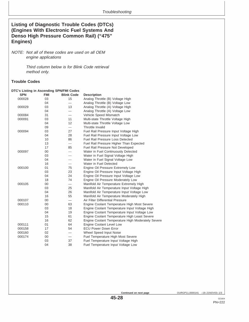
Troubleshooting
OURGP11,0000141 –19–21NOV03–1/3
Listing of Diagnostic Trouble Codes (DTCs)(Engines With Electronic Fuel Systems AndDenso High Pressure Common Rail) (“475”Engines)
NOTE: Not all of these codes are used on all OEMengine applications
Third column below is for Blink Code retrievalmethod only.
Trouble Codes
DTC’s Listing in Ascending SPN/FMI CodesSPN FMI Blink Code Description
000028 03 15 Analog Throttle (B) Voltage High04 — Analog Throttle (B) Voltage Low
000029 03 13 Analog Throttle (A) Voltage High04 — Analog Throttle (A) Voltage Low
000084 31 — Vehicle Speed Mismatch000091 03 11 Multi-state Throttle Voltage High
04 12 Multi-state Throttle Voltage Low09 — Throttle Invalid
000094 03 27 Fuel Rail Pressure Input Voltage High04 28 Fuel Rail Pressure Input Voltage Low10 86 Fuel Rail Pressure Loss Detected13 — Fuel Rail Pressure Higher Than Expected17 85 Fuel Rail Pressure Not Developed
000097 00 — Water in Fuel Continuously Detected03 — Water in Fuel Signal Voltage High04 — Water in Fuel Signal Voltage Low16 — Water in Fuel Detected
000100 01 75 Engine Oil Pressure Extremely Low03 23 Engine Oil Pressure Input Voltage High04 24 Engine Oil Pressure Input Voltage Low18 74 Engine Oil Pressure Moderately Low
000105 00 — Manifold Air Temperature Extremely High03 25 Manifold Air Temperature Input Voltage High04 26 Manifold Air Temperature Input Voltage Low16 55 Manifold Air Temperature Moderately High
000107 00 — Air Filter Differential Pressure000110 00 63 Engine Coolant Temperature High Most Severe
03 18 Engine Coolant Temperature Input Voltage High04 19 Engine Coolant Temperature Input Voltage Low15 61 Engine Coolant Temperature High Least Severe16 62 Engine Coolant Temperature High Moderately Severe
000111 01 64 Engine Coolant Level Low000158 17 54 ECU Power Down Error000160 02 — Wheel Speed Input Noise000174 00 — Fuel Temperature High Most Severe
03 37 Fuel Temperature Input Voltage High04 38 Fuel Temperature Input Voltage Low
45-28 021604
PN=222
Continued on next page
https://www.truck-manuals.net/
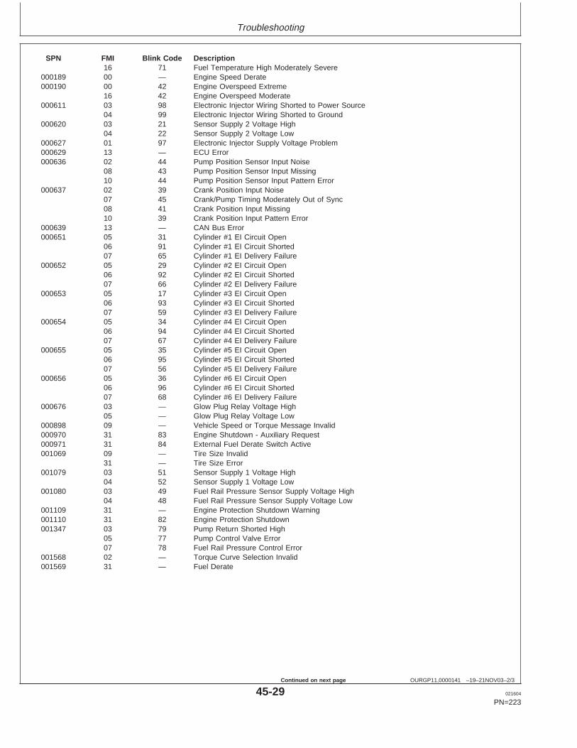
Troubleshooting
OURGP11,0000141 –19–21NOV03–2/3
SPN FMI Blink Code Description16 71 Fuel Temperature High Moderately Severe
000189 00 — Engine Speed Derate000190 00 42 Engine Overspeed Extreme
16 42 Engine Overspeed Moderate000611 03 98 Electronic Injector Wiring Shorted to Power Source
04 99 Electronic Injector Wiring Shorted to Ground000620 03 21 Sensor Supply 2 Voltage High
04 22 Sensor Supply 2 Voltage Low000627 01 97 Electronic Injector Supply Voltage Problem000629 13 — ECU Error000636 02 44 Pump Position Sensor Input Noise
08 43 Pump Position Sensor Input Missing10 44 Pump Position Sensor Input Pattern Error
000637 02 39 Crank Position Input Noise07 45 Crank/Pump Timing Moderately Out of Sync08 41 Crank Position Input Missing10 39 Crank Position Input Pattern Error
000639 13 — CAN Bus Error000651 05 31 Cylinder #1 EI Circuit Open
06 91 Cylinder #1 EI Circuit Shorted07 65 Cylinder #1 EI Delivery Failure
000652 05 29 Cylinder #2 EI Circuit Open06 92 Cylinder #2 EI Circuit Shorted07 66 Cylinder #2 EI Delivery Failure
000653 05 17 Cylinder #3 EI Circuit Open06 93 Cylinder #3 EI Circuit Shorted07 59 Cylinder #3 EI Delivery Failure
000654 05 34 Cylinder #4 EI Circuit Open06 94 Cylinder #4 EI Circuit Shorted07 67 Cylinder #4 EI Delivery Failure
000655 05 35 Cylinder #5 EI Circuit Open06 95 Cylinder #5 EI Circuit Shorted07 56 Cylinder #5 EI Delivery Failure
000656 05 36 Cylinder #6 EI Circuit Open06 96 Cylinder #6 EI Circuit Shorted07 68 Cylinder #6 EI Delivery Failure
000676 03 — Glow Plug Relay Voltage High05 — Glow Plug Relay Voltage Low
000898 09 — Vehicle Speed or Torque Message Invalid000970 31 83 Engine Shutdown - Auxiliary Request000971 31 84 External Fuel Derate Switch Active001069 09 — Tire Size Invalid
31 — Tire Size Error001079 03 51 Sensor Supply 1 Voltage High
04 52 Sensor Supply 1 Voltage Low001080 03 49 Fuel Rail Pressure Sensor Supply Voltage High
04 48 Fuel Rail Pressure Sensor Supply Voltage Low001109 31 — Engine Protection Shutdown Warning001110 31 82 Engine Protection Shutdown001347 03 79 Pump Return Shorted High
05 77 Pump Control Valve Error07 78 Fuel Rail Pressure Control Error
001568 02 — Torque Curve Selection Invalid001569 31 — Fuel Derate
45-29 021604
PN=223
Continued on next page
https://www.truck-manuals.net/
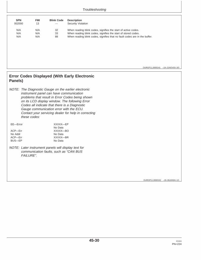
Troubleshooting
OURGP11,0000141 –19–21NOV03–3/3
SPN FMI Blink Code Description002000 13 — Security Violation
N/A N/A 32 When reading blink codes, signifies the start of active codes.N/A N/A 33 When reading blink codes, signifies the start of stored codes.N/A N/A 88 When reading blink codes, signifies that no fault codes are in the buffer.
OURGP11,0000152 –19–06JAN04–1/1
Error Codes Displayed (With Early ElectronicPanels)
NOTE: The Diagnostic Gauge on the earlier electronicinstrument panel can have communicationproblems that result in Error Codes being shownon its LCD display window. The following ErrorCodes all indicate that there is a DiagnosticGauge communication error with the ECU.Contact your servicing dealer for help in correctingthese codes:
EE—Error XXXXX—EPNo Data
ACP—Err XXXXX—BONo Addr No DataACP—Err XXXXX—BRBUS—EP No Data
NOTE: Later instrument panels will display text forcommunication faults, such as “CAN BUSFAILURE”.
45-30 021604
PN=224
https://www.truck-manuals.net/
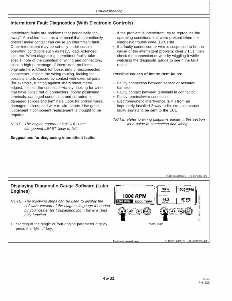
Troubleshooting
OUOD007,0000036 –19–26FEB03–1/1
Intermittent Fault Diagnostics (With Electronic Controls)
Intermittent faults are problems that periodically “goaway”. A problem such as a terminal that intermittentlydoesn’t make contact can cause an intermittent fault.Other intermittent may be set only under certainoperating conditions such as heavy load, extendedidle, etc. When diagnosing intermittent faults, takespecial note of the condition of wiring and connectors,since a high percentage of intermittent problemsoriginate here. Check for loose, dirty or disconnectedconnectors. Inspect the wiring routing, looking forpossible shorts caused by contact with external parts(for example, rubbing against sharp sheet metaledges). Inspect the connector vicinity, looking for wiresthat have pulled out of connectors, poorly positionedterminals, damaged connectors and corroded ordamaged splices and terminals. Look for broken wires,damaged splices, and wire-to-wire shorts. Use goodjudgement if component replacement is thought to berequired.
NOTE: The engine control unit (ECU) is thecomponent LEAST likely to fail.
Suggestions for diagnosing intermittent faults:
• If the problem is intermittent, try to reproduce theoperating conditions that were present when thediagnostic trouble code (DTC) set.
• If a faulty connection or wire is suspected to be thecause of the intermittent problem: clear DTCs, thencheck the connection or wire by wiggling it whilewatching the diagnostic gauge to see if the faultresets.
Possible causes of intermittent faults:
• Faulty connection between sensor or actuatorharness.
• Faulty contact between terminals in connector.• Faulty terminal/wire connection.• Electromagnetic interference (EMI) from an
improperly installed 2-way radio, etc., can causefaulty signals to be sent to the ECU.
NOTE: Refer to wiring diagrams earlier in this sectionas a guide to connection and wiring.
OURGP11,000012B –19–30OCT03–1/4
Displaying Diagnostic Gauge Software (LaterEngines)
RG
1315
9–U
N–2
6SE
P03
Menu Key
NOTE: The following steps can be used to display thesoftware version of the diagnostic gauge if neededby your dealer for troubleshooting. This is a readonly function.
1. Starting at the single or four engine parameter display,press the "Menu" key.
Continued on next page
45-31 021604
PN=225
https://www.truck-manuals.net/
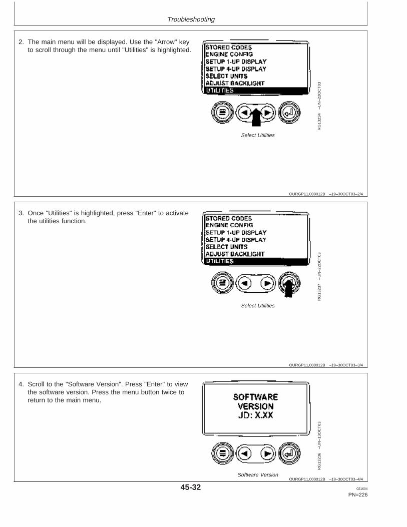
Troubleshooting
OURGP11,000012B –19–30OCT03–2/4
RG
1323
4–U
N–2
2OC
T03
Select Utilities
2. The main menu will be displayed. Use the "Arrow" keyto scroll through the menu until "Utilities" is highlighted.
OURGP11,000012B –19–30OCT03–3/4
RG
1323
7–U
N–2
2OC
T03
Select Utilities
3. Once "Utilities" is highlighted, press "Enter" to activatethe utilities function.
OURGP11,000012B –19–30OCT03–4/4
RG
1323
6–U
N–1
3OC
T03
Software Version
4. Scroll to the "Software Version". Press "Enter" to viewthe software version. Press the menu button twice toreturn to the main menu.
45-32 021604
PN=226
https://www.truck-manuals.net/
Storage
RG,RG34710,5610 –19–23NOV01–1/1
Engine Storage Guidelines
1. John Deere engines can be stored outside for up tothree (3) months with no long term preparation IFCOVERED BY WATERPROOF COVERING.
2. John Deere engines can be stored in a standardoverseas shipping container for up to three (3)months with no long term preparation.
3. John Deere engines can be stored inside,warehoused, for up to six (6) months with no longterm preparation.
4. John Deere engines expected to be stored morethan six (6) months, long term storage preparationMUST BE taken. ( See PREPARING ENGINE FORLONG TERM STORAGE, later in this section.)
50-1 021604
PN=227
https://www.truck-manuals.net/
Storage
RG,RG34710,5612 –19–23NOV01–1/1
Preparing Engine for Long Term Storage
The following storage preparations are good for longterm engine storage up to one year. After that, theengine should be started, warmed up, and retreatedfor an extended storage period.
IMPORTANT: Any time your engine will not beused for over six (6) months, thefollowing recommendations forstoring it and removing it fromstorage will help to minimizecorrosion and deterioration.
1. Change engine oil and replace filter. Used oil willnot give adequate protection. (See CHANGEENGINE OIL AND FILTER in Lubrication andMaintenance/500 Hour Section.)
2. Service air cleaner. (See REPLACING AIRCLEANER FILTER ELEMENTS in Service AsRequired Section.)
3. Draining and flushing of cooling system is notnecessary if engine is to be stored only for severalmonths. However, for extended storage periods of ayear or longer, it is recommended that the coolingsystem be drained, flushed, and refilled. Refill withappropriate coolant. (See RECOMMENDEDENGINE COOLANT in Fuels, Lubricants, and
Coolant Section and ADDING COOLANT in ServiceAs Required Section.)
4. Crank the engine several revolutions with starter(do not allow the engine to start).
5. Remove fan/alternator poly-vee belt, if desired.
6. Remove and clean batteries. Store them in a cool,dry place and keep them fully charged.
7. Disengage the clutch for any driveline.
8. Clean the exterior of the engine with salt-free waterand touchup any scratched or chipped paintedsurfaces with a good quality paint.
9. Coat all exposed (machined) metal surfaces withgrease or corrosion inhibitor if not feasible to paint.
10. Seal all openings on engine with plastic bags andtape.
11. Store the engine in a dry protected place. Ifengine must be stored outside, cover it with awaterproof canvas or other suitable protectivematerial and use a strong waterproof tape.
50-2 021604
PN=228
https://www.truck-manuals.net/
Storage
RG,RG34710,5613 –19–20MAY96–1/1
Removing Engine from Long Term Storage
Refer to the appropriate section for detailed serviceslisted below or have your authorized servicing dealeror engine distributor perform services that you may notbe familiar with.
1. Remove all protective coverings from engine.Unseal all openings in engine and remove coveringfrom electrical systems.
2. Remove the batteries from storage. Install batteries(fully charged) and connect the terminals.
3. Install fan/alternator poly-vee belt if removed.
4. Fill fuel tank.
5. Perform all appropriate prestarting checks. ( SeeDAILY PRESTARTING CHECKS in Lubrication andMaintenance/Daily Section.)
IMPORTANT: DO NOT operate starter more than30 seconds at a time. Wait at least 2minutes for starter to cool beforetrying again.
6. Crank engine for 20 seconds with starter (do notallow the engine to start). Wait 2 minutes and crankengine an additional 20 seconds to assure bearingsurfaces are adequately lubricated.
7. Start engine and run at low idle and no load forseveral minutes. Warm up carefully and check allgauges before placing engine under load.
8. On the first day of operation after storage, checkoverall engine for leaks and check all gauges forcorrect operation.
50-3 021604
PN=229
https://www.truck-manuals.net/
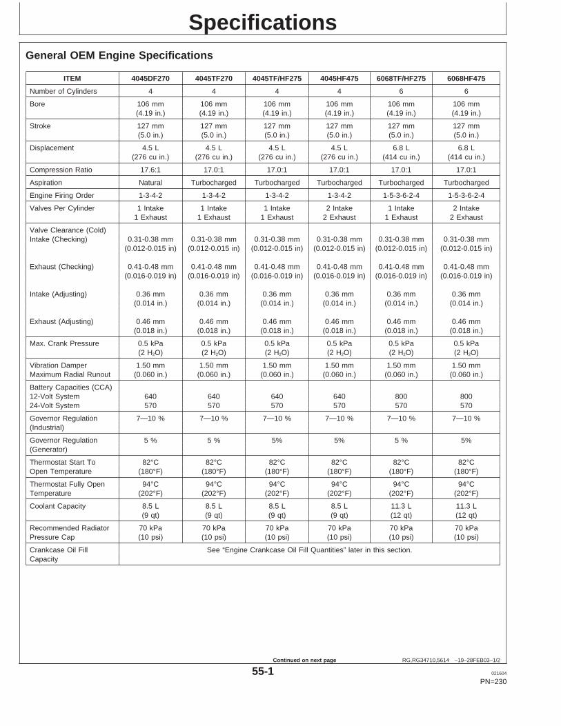
Specifications
RG,RG34710,5614 –19–28FEB03–1/2
General OEM Engine Specifications
ITEM 4045DF270 4045TF270 4045TF/HF275 4045HF475 6068TF/HF275 6068HF475
Number of Cylinders 4 4 4 4 6 6
Bore 106 mm 106 mm 106 mm 106 mm 106 mm 106 mm(4.19 in.) (4.19 in.) (4.19 in.) (4.19 in.) (4.19 in.) (4.19 in.)
Stroke 127 mm 127 mm 127 mm 127 mm 127 mm 127 mm(5.0 in.) (5.0 in.) (5.0 in.) (5.0 in.) (5.0 in.) (5.0 in.)
Displacement 4.5 L 4.5 L 4.5 L 4.5 L 6.8 L 6.8 L(276 cu in.) (276 cu in.) (276 cu in.) (276 cu in.) (414 cu in.) (414 cu in.)
Compression Ratio 17.6:1 17.0:1 17.0:1 17.0:1 17.0:1 17.0:1
Aspiration Natural Turbocharged Turbocharged Turbocharged Turbocharged Turbocharged
Engine Firing Order 1-3-4-2 1-3-4-2 1-3-4-2 1-3-4-2 1-5-3-6-2-4 1-5-3-6-2-4
Valves Per Cylinder 1 Intake 1 Intake 1 Intake 2 Intake 1 Intake 2 Intake1 Exhaust 1 Exhaust 1 Exhaust 2 Exhaust 1 Exhaust 2 Exhaust
Valve Clearance (Cold)Intake (Checking) 0.31-0.38 mm 0.31-0.38 mm 0.31-0.38 mm 0.31-0.38 mm 0.31-0.38 mm 0.31-0.38 mm
(0.012-0.015 in) (0.012-0.015 in) (0.012-0.015 in) (0.012-0.015 in) (0.012-0.015 in) (0.012-0.015 in)
Exhaust (Checking) 0.41-0.48 mm 0.41-0.48 mm 0.41-0.48 mm 0.41-0.48 mm 0.41-0.48 mm 0.41-0.48 mm(0.016-0.019 in) (0.016-0.019 in) (0.016-0.019 in) (0.016-0.019 in) (0.016-0.019 in) (0.016-0.019 in)
Intake (Adjusting) 0.36 mm 0.36 mm 0.36 mm 0.36 mm 0.36 mm 0.36 mm(0.014 in.) (0.014 in.) (0.014 in.) (0.014 in.) (0.014 in.) (0.014 in.)
Exhaust (Adjusting) 0.46 mm 0.46 mm 0.46 mm 0.46 mm 0.46 mm 0.46 mm(0.018 in.) (0.018 in.) (0.018 in.) (0.018 in.) (0.018 in.) (0.018 in.)
Max. Crank Pressure 0.5 kPa 0.5 kPa 0.5 kPa 0.5 kPa 0.5 kPa 0.5 kPa(2 H2O) (2 H2O) (2 H2O) (2 H2O) (2 H2O) (2 H2O)
Vibration Damper 1.50 mm 1.50 mm 1.50 mm 1.50 mm 1.50 mm 1.50 mmMaximum Radial Runout (0.060 in.) (0.060 in.) (0.060 in.) (0.060 in.) (0.060 in.) (0.060 in.)
Battery Capacities (CCA)12-Volt System 640 640 640 640 800 80024-Volt System 570 570 570 570 570 570
Governor Regulation 7—10 % 7—10 % 7—10 % 7—10 % 7—10 % 7—10 %(Industrial)
Governor Regulation 5 % 5 % 5% 5% 5 % 5%(Generator)
Thermostat Start To 82°C 82°C 82°C 82°C 82°C 82°COpen Temperature (180°F) (180°F) (180°F) (180°F) (180°F) (180°F)
Thermostat Fully Open 94°C 94°C 94°C 94°C 94°C 94°CTemperature (202°F) (202°F) (202°F) (202°F) (202°F) (202°F)
Coolant Capacity 8.5 L 8.5 L 8.5 L 8.5 L 11.3 L 11.3 L(9 qt) (9 qt) (9 qt) (9 qt) (12 qt) (12 qt)
Recommended Radiator 70 kPa 70 kPa 70 kPa 70 kPa 70 kPa 70 kPaPressure Cap (10 psi) (10 psi) (10 psi) (10 psi) (10 psi) (10 psi)
Crankcase Oil Fill See “Engine Crankcase Oil Fill Quantities” later in this section.Capacity
55-1 021604
PN=230
Continued on next page
https://www.truck-manuals.net/
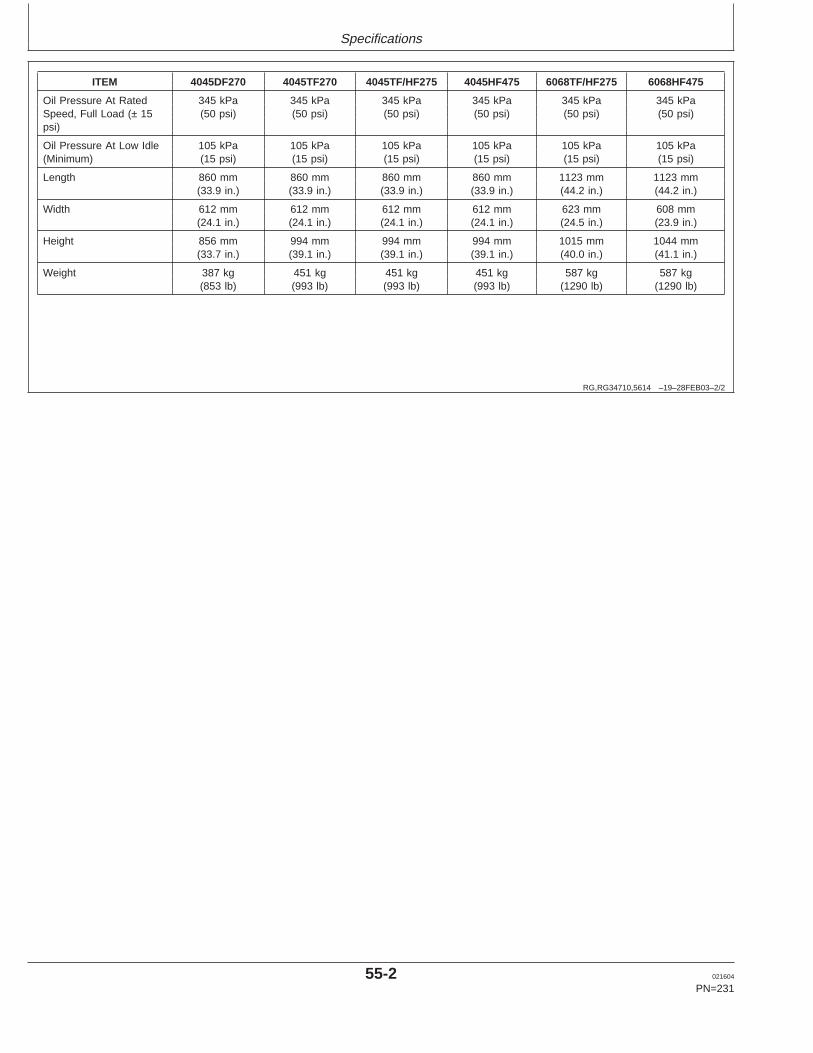
Specifications
RG,RG34710,5614 –19–28FEB03–2/2
ITEM 4045DF270 4045TF270 4045TF/HF275 4045HF475 6068TF/HF275 6068HF475
Oil Pressure At Rated 345 kPa 345 kPa 345 kPa 345 kPa 345 kPa 345 kPaSpeed, Full Load (± 15 (50 psi) (50 psi) (50 psi) (50 psi) (50 psi) (50 psi)psi)
Oil Pressure At Low Idle 105 kPa 105 kPa 105 kPa 105 kPa 105 kPa 105 kPa(Minimum) (15 psi) (15 psi) (15 psi) (15 psi) (15 psi) (15 psi)
Length 860 mm 860 mm 860 mm 860 mm 1123 mm 1123 mm(33.9 in.) (33.9 in.) (33.9 in.) (33.9 in.) (44.2 in.) (44.2 in.)
Width 612 mm 612 mm 612 mm 612 mm 623 mm 608 mm(24.1 in.) (24.1 in.) (24.1 in.) (24.1 in.) (24.5 in.) (23.9 in.)
Height 856 mm 994 mm 994 mm 994 mm 1015 mm 1044 mm(33.7 in.) (39.1 in.) (39.1 in.) (39.1 in.) (40.0 in.) (41.1 in.)
Weight 387 kg 451 kg 451 kg 451 kg 587 kg 587 kg(853 lb) (993 lb) (993 lb) (993 lb) (1290 lb) (1290 lb)
55-2 021604
PN=231
https://www.truck-manuals.net/
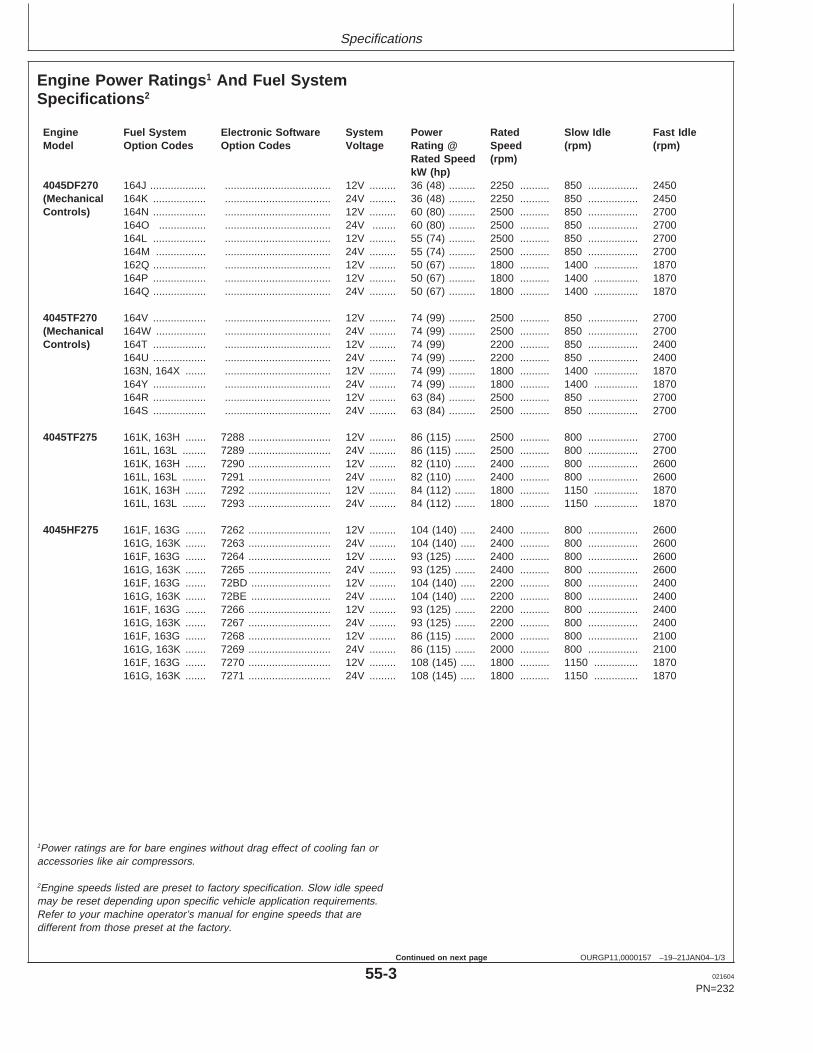
Specifications
OURGP11,0000157 –19–21JAN04–1/3
Engine Power Ratings 1 And Fuel SystemSpecifications 2
Engine Fuel System Electronic Software System Power Rated Slow Idle Fast IdleModel Option Codes Option Codes Voltage Rating @ Speed (rpm) (rpm)
Rated Speed (rpm)kW (hp)
4045DF270 164J ................... .................................... 12V ......... 36 (48) ......... 2250 .......... 850 ................. 2450(Mechanical 164K .................. .................................... 24V ......... 36 (48) ......... 2250 .......... 850 ................. 2450Controls) 164N .................. .................................... 12V ......... 60 (80) ......... 2500 .......... 850 ................. 2700
164O ................ .................................... 24V ........ 60 (80) ......... 2500 .......... 850 ................. 2700164L .................. .................................... 12V ......... 55 (74) ......... 2500 .......... 850 ................. 2700164M ................. .................................... 24V ......... 55 (74) ......... 2500 .......... 850 ................. 2700162Q .................. .................................... 12V ......... 50 (67) ......... 1800 .......... 1400 ............... 1870164P .................. .................................... 12V ......... 50 (67) ......... 1800 .......... 1400 ............... 1870164Q .................. .................................... 24V ......... 50 (67) ......... 1800 .......... 1400 ............... 1870
4045TF270 164V .................. .................................... 12V ......... 74 (99) ......... 2500 .......... 850 ................. 2700(Mechanical 164W ................. .................................... 24V ......... 74 (99) ......... 2500 .......... 850 ................. 2700Controls) 164T .................. .................................... 12V ......... 74 (99) 2200 .......... 850 ................. 2400
164U .................. .................................... 24V ......... 74 (99) ......... 2200 .......... 850 ................. 2400163N, 164X ....... .................................... 12V ......... 74 (99) ......... 1800 .......... 1400 ............... 1870164Y .................. .................................... 24V ......... 74 (99) ......... 1800 .......... 1400 ............... 1870164R .................. .................................... 12V ......... 63 (84) ......... 2500 .......... 850 ................. 2700164S .................. .................................... 24V ......... 63 (84) ......... 2500 .......... 850 ................. 2700
4045TF275 161K, 163H ....... 7288 ............................ 12V ......... 86 (115) ....... 2500 .......... 800 ................. 2700161L, 163L ........ 7289 ............................ 24V ......... 86 (115) ....... 2500 .......... 800 ................. 2700161K, 163H ....... 7290 ............................ 12V ......... 82 (110) ....... 2400 .......... 800 ................. 2600161L, 163L ........ 7291 ............................ 24V ......... 82 (110) ....... 2400 .......... 800 ................. 2600161K, 163H ....... 7292 ............................ 12V ......... 84 (112) ....... 1800 .......... 1150 ............... 1870161L, 163L ........ 7293 ............................ 24V ......... 84 (112) ....... 1800 .......... 1150 ............... 1870
4045HF275 161F, 163G ....... 7262 ............................ 12V ......... 104 (140) ..... 2400 .......... 800 ................. 2600161G, 163K ....... 7263 ............................ 24V ......... 104 (140) ..... 2400 .......... 800 ................. 2600161F, 163G ....... 7264 ............................ 12V ......... 93 (125) ....... 2400 .......... 800 ................. 2600161G, 163K ....... 7265 ............................ 24V ......... 93 (125) ....... 2400 .......... 800 ................. 2600161F, 163G ....... 72BD ........................... 12V ......... 104 (140) ..... 2200 .......... 800 ................. 2400161G, 163K ....... 72BE ........................... 24V ......... 104 (140) ..... 2200 .......... 800 ................. 2400161F, 163G ....... 7266 ............................ 12V ......... 93 (125) ....... 2200 .......... 800 ................. 2400161G, 163K ....... 7267 ............................ 24V ......... 93 (125) ....... 2200 .......... 800 ................. 2400161F, 163G ....... 7268 ............................ 12V ......... 86 (115) ....... 2000 .......... 800 ................. 2100161G, 163K ....... 7269 ............................ 24V ......... 86 (115) ....... 2000 .......... 800 ................. 2100161F, 163G ....... 7270 ............................ 12V ......... 108 (145) ..... 1800 .......... 1150 ............... 1870161G, 163K ....... 7271 ............................ 24V ......... 108 (145) ..... 1800 .......... 1150 ............... 1870
1Power ratings are for bare engines without drag effect of cooling fan oraccessories like air compressors.
2Engine speeds listed are preset to factory specification. Slow idle speedmay be reset depending upon specific vehicle application requirements.Refer to your machine operator’s manual for engine speeds that aredifferent from those preset at the factory.
55-3 021604
PN=232
Continued on next page
https://www.truck-manuals.net/
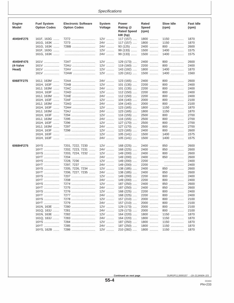
Specifications
OURGP11,0000157 –19–21JAN04–2/3
Engine Fuel System Electronic Software System Power Rated Slow Idle Fast IdleModel Option Codes Option Codes Voltage Rating @ Speed (rpm) (rpm)
Rated Speed (rpm)kW (hp)
4045HF275 161F, 163G ....... 7272 ............................ 12V ......... 117 (157) ..... 1800 .......... 1150 ............... 1870161G, 163K ....... 7273 ............................ 24V ......... 117 (157) ..... 1800 .......... 1150 ............... 1870161G, 163K ....... 72BB ........................... 24V ......... 93 (125) ....... 2400 .......... 800 ................. 2600161F, 163G ....... .................................... 12V ......... 99 (133) ....... 1500 .......... 1400 ............... 1575161G, 163K ....... .................................... 24V ......... 99 (133) ....... 1500 .......... 1400 ............... 1575
4045HF475 161V .................. 72AT ........................... 12V ......... 129 (173) ..... 2400 .......... 800 ................. 2600(4-Valve 161V .................. 72AU ........................... 12V ......... 119 (160) ..... 2200 .......... 800 ................. 2400Head) 161V .................. 72AV ........................... 12V ......... 143 (192) ..... 1800 .......... 1400 ............... 1870
161V .................. 72AW .......................... 12V ......... 120 (161) ..... 1500 .......... 1400 ............... 1560
6068TF275 161J, 163M ....... 72AA ........................... 24V ......... 123 (165) ..... 2400 ......... 800 ................. 2600161H, 163F ....... 72AB ........................... 12V ......... 101 (135) ..... 2200 .......... 800 ................. 2400161J, 163M ....... 72AC ........................... 24V ......... 101 (135) ..... 2200 .......... 800 ................. 2400161H, 163F ....... 72AD ........................... 12V ......... 112 (150) ..... 2200 .......... 800 ................. 2400161J, 163M ....... 72AE ........................... 24V ......... 112 (150) ..... 2200 .......... 800 ................. 2400161H, 163F ....... 72AF ........................... 12V ......... 104 (140) ..... 2000 .......... 800 ................. 2100161J, 163M ....... 72AG .......................... 24V ......... 104 (140) ..... 2000 .......... 800 ................. 2100161H, 163F ....... 72AH ........................... 12V ......... 123 (165) ..... 1800 .......... 1150 ............... 1870161J, 163M ....... 72AJ ........................... 24V ......... 123 (165) ..... 1800 .......... 1150 ............... 1870161H, 163F ....... 7294 ............................ 12V ......... 116 (155) ..... 2500 .......... 800 ................. 2700161J, 163M ....... 7295 ............................ 24V ......... 116 (155) ..... 2500 .......... 800 ................. 2700161H, 163F ....... 7296 ............................ 12V ......... 127 (170) ..... 2500 ......... 800 ................. 2700161J, 163M ....... 7297 ............................ 24V ......... 127 (170) ..... 2500 .......... 800 ................. 2700161H, 163F ....... 7298 ............................ 12V ......... 123 (165) ..... 2400 .......... 800 ................. 2600161H, 163F ....... .................................... 12V ......... 105 (141) ..... 1500 .......... 1400 ............... 1575161H, 163F ....... .................................... 24V ......... 105 (141) ..... 1500 .......... 1400 ............... 1575
6068HF275 16YS .................. 7201, 7222, 7230 ....... 12V ......... 168 (225) ..... 2400 .......... 850 ................. 260016YT .................. 7202, 7223, 7231 ....... 24V ......... 168 (225) ..... 2400 .......... 850 ................. 260016YS .................. 7203, 7224, 7232 ....... 12V ......... 149 (200) ..... 2400 .......... 800 ................. 260016YT .................. 7204 ............................ 24V ......... 149 (200) ..... 2400 .......... 850 ................. 260016YS .................. 7228, 7236 ................. 12V ......... 149 (200) ..... 2200 .......... ....................... 240016YT .................. 7297, 7237 ................. 24V ......... 149 (200) ..... 2200 .......... ....................... 240016YS .................. 7205, 7226, 7234 ....... 12V ......... 138 (185) ..... 2400 .......... 850 ................. 260016YT .................. 7206, 7227, 7235 ....... 24V ......... 138 (185) ..... 2400 .......... 850 ................. 260016YS .................. 7207 ............................ 12V ......... 149 (200) ..... 2200 .......... 800 ................. 240016YT .................. 7208 ............................ 24V ......... 149 (200) ..... 2200 .......... 800 ................. 240016YS .................. 7274 ............................ 12V ......... 187 (250) ..... 2400 .......... 850 ................. 260016YT .................. 7275 ............................ 24V ......... 187 (250) ..... 2400 .......... 850 ................. 260016YS .................. 7276 ............................ 12V ......... 168 (225) ..... 2200 .......... 800 ................. 240016YT .................. 7277 ............................ 24V ......... 168 (225) ..... 2200 .......... 800 ................. 240016YS .................. 7278 ............................ 12V ......... 157 (210) ..... 2000 .......... 800 ................. 210016YT .................. 7279 ............................ 24V ......... 157 (210) ..... 2000 .......... 800 ................. 2100161N, 163E ....... 7280 ............................ 12V ......... 129 (173) ..... 2000 .......... 800 ................. 2100161Q, 163J ........ 7281 ............................ 24V ......... 129 (173) ..... 2000 .......... 800 ................. 2100161N, 163E ....... 7282 ............................ 12V ......... 164 (220) ..... 1800 .......... 1150 ............... 1870161Q, 163J ........ 7283 ............................ 24V ......... 164 (220) ..... 1800 .......... 1150 ............... 187016YS .................. 7284 ............................ 12V ......... 187 (250) ..... 1800 .......... 1150 ............... 187016YT .................. 7285 ............................ 24V ......... 187 (250) ..... 1800 .......... 1150 ............... 187016YS, 162B ....... 7286 ............................ 12V ......... 210 (282) ..... 1800 .......... 1150 ............... 1870
55-4 021604
PN=233
Continued on next page
https://www.truck-manuals.net/
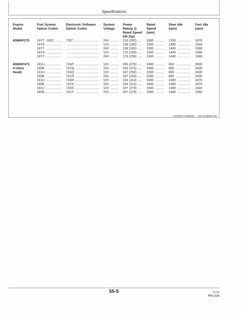
Specifications
OURGP11,0000157 –19–21JAN04–3/3
Engine Fuel System Electronic Software System Power Rated Slow Idle Fast IdleModel Option Codes Option Codes Voltage Rating @ Speed (rpm) (rpm)
Rated Speed (rpm)kW (hp)
6068HF275 16YT, 162C ....... 7287 ............................ 24V ......... 210 (282) ..... 1800 .......... 1150 ............... 187016YS .................. .................................... 12V ......... 138 (185) ..... 1500 .......... 1400 ............... 156016YT .................. .................................... 24V ......... 138 (185) ..... 1500 .......... 1400 ............... 156016YS .................. .................................... 12V ......... 175 (235) ..... 1500 .......... 1400 ............... 156016YT .................. .................................... 24V ......... 175 (235) ..... 1500 .......... 1400 ............... 1560
6068HF475 161U .................. 72AP ........................... 12V ......... 205 (275) ..... 2400 .......... 800 ................. 26004-Valve 165B .................. 72CQ .......................... 24V ......... 205 (275) ..... 2400 .......... 800 ................. 2600Head) 161U .................. 72AQ .......................... 12V ......... 187 (250) ..... 2200 .......... 800 ................. 2400
165B .................. 72CR .......................... 24V ......... 187 (250) ..... 2200 .......... 800 ................. 2400161U .................. 72AR ........................... 12V ......... 234 (314) ..... 1800 .......... 1400 ............... 1870165B .................. 72CS ........................... 24V ......... 234 (314) ..... 1800 .......... 1400 ............... 1870161U .................. 72AS ........................... 12V ......... 207 (278) ..... 1500 .......... 1400 ............... 1560165B .................. 72CT ........................... 24V ......... 207 (278) ..... 1500 .......... 1400 ............... 1560
55-5 021604
PN=234
https://www.truck-manuals.net/
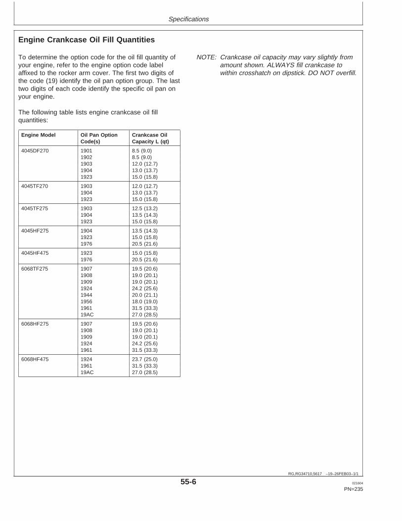
Specifications
RG,RG34710,5617 –19–26FEB03–1/1
Engine Crankcase Oil Fill Quantities
To determine the option code for the oil fill quantity ofyour engine, refer to the engine option code labelaffixed to the rocker arm cover. The first two digits ofthe code (19) identify the oil pan option group. The lasttwo digits of each code identify the specific oil pan onyour engine.
The following table lists engine crankcase oil fillquantities:
Engine Model Oil Pan Option Crankcase OilCode(s) Capacity L (qt)
4045DF270 1901 8.5 (9.0)1902 8.5 (9.0)1903 12.0 (12.7)1904 13.0 (13.7)1923 15.0 (15.8)
4045TF270 1903 12.0 (12.7)1904 13.0 (13.7)1923 15.0 (15.8)
4045TF275 1903 12.5 (13.2)1904 13.5 (14.3)1923 15.0 (15.8)
4045HF275 1904 13.5 (14.3)1923 15.0 (15.8)1976 20.5 (21.6)
4045HF475 1923 15.0 (15.8)1976 20.5 (21.6)
6068TF275 1907 19.5 (20.6)1908 19.0 (20.1)1909 19.0 (20.1)1924 24.2 (25.6)1944 20.0 (21.1)1956 18.0 (19.0)1961 31.5 (33.3)19AC 27.0 (28.5)
6068HF275 1907 19.5 (20.6)1908 19.0 (20.1)1909 19.0 (20.1)1924 24.2 (25.6)1961 31.5 (33.3)
6068HF475 1924 23.7 (25.0)1961 31.5 (33.3)19AC 27.0 (28.5)
NOTE: Crankcase oil capacity may vary slightly fromamount shown. ALWAYS fill crankcase towithin crosshatch on dipstick. DO NOT overfill.
55-6 021604
PN=235
https://www.truck-manuals.net/
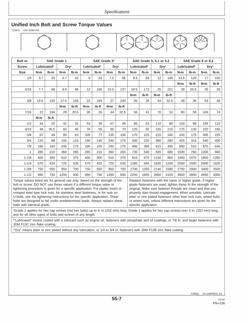
Specifications
TORQ1 –19–24APR03–1/1
Unified Inch Bolt and Screw Torque ValuesTS1671 –UN–01MAY03
Bolt or SAE Grade 1 SAE Grade 2 a SAE Grade 5, 5.1 or 5.2 SAE Grade 8 or 8.2
Screw Lubricated b Dry c Lubricated b Dry c Lubricated b Dry c Lubricated b Dry c
Size N•m lb-in N •m lb-in N •m lb-in N •m lb-in N •m lb-in N •m lb-in N •m lb-in N •m lb-in
1/4 3.7 33 4.7 42 6 53 7.5 66 9.5 84 12 106 13.5 120 17 150
N•m lb-ft N •m lb-ft
5/16 7.7 68 9.8 86 12 106 15.5 137 19.5 172 25 221 28 20.5 35 26
N•m lb-ft N •m lb-ft
3/8 13.5 120 17.5 155 22 194 27 240 35 26 44 32.5 49 36 63 46
N•m lb-ft N •m lb-ft N •m lb-ft
7/16 22 194 28 20.5 35 26 44 32.5 56 41 70 52 80 59 100 74
N•m lb-ft
1/2 34 25 42 31 53 39 67 49 85 63 110 80 120 88 155 115
9/16 48 35.5 60 45 76 56 95 70 125 92 155 115 175 130 220 165
5/8 67 49 85 63 105 77 135 100 170 125 215 160 240 175 305 225
3/4 120 88 150 110 190 140 240 175 300 220 380 280 425 315 540 400
7/8 190 140 240 175 190 140 240 175 490 360 615 455 690 510 870 640
1 285 210 360 265 285 210 360 265 730 540 920 680 1030 760 1300 960
1-1/8 400 300 510 375 400 300 510 375 910 670 1150 850 1450 1075 1850 1350
1-1/4 570 420 725 535 570 420 725 535 1280 945 1630 1200 2050 1500 2600 1920
1-3/8 750 550 950 700 750 550 950 700 1700 1250 2140 1580 2700 2000 3400 2500
1-1/2 990 730 1250 930 990 730 1250 930 2250 1650 2850 2100 3600 2650 4550 3350
Torque values listed are for general use only, based on the strength of the Replace fasteners with the same or higher grade. If higherbolt or screw. DO NOT use these values if a different torque value or grade fasteners are used, tighten these to the strength of thetightening procedure is given for a specific application. For plastic insert or original. Make sure fastener threads are clean and that youcrimped steel type lock nuts, for stainless steel fasteners, or for nuts on properly start thread engagement. When possible, lubricateU-bolts, see the tightening instructions for the specific application. Shear plain or zinc plated fasteners other than lock nuts, wheel boltsbolts are designed to fail under predetermined loads. Always replace shear or wheel nuts, unless different instructions are given for thebolts with identical grade. specific application.aGrade 2 applies for hex cap screws (not hex bolts) up to 6. in (152 mm) long. Grade 1 applies for hex cap screws over 6 in. (152 mm) long,and for all other types of bolts and screws of any length.b“Lubricated” means coated with a lubricant such as engine oil, fasteners with phosphate and oil coatings, or 7/8 in. and larger fasteners withJDM F13C zinc flake coating.c“Dry” means plain or zinc plated without any lubrication, or 1/4 to 3/4 in. fasteners with JDM F13B zinc flake coating.
55-7 021604
PN=236
https://www.truck-manuals.net/
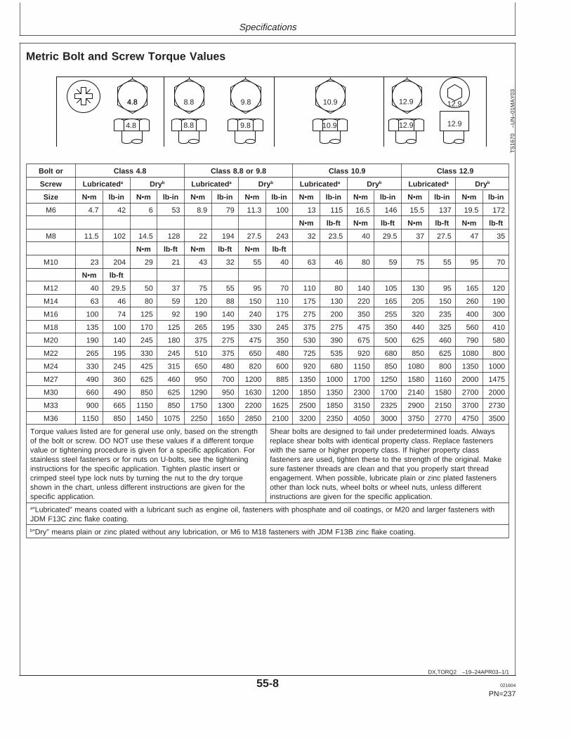
Specifications
DX,TORQ2 –19–24APR03–1/1
Metric Bolt and Screw Torque Values
4.84.8 8.8 9.8 10.9 12.9 12.9
12.912.910.99.88.84.8
TS
1670
–UN
–01M
AY
03
Bolt or Class 4.8 Class 8.8 or 9.8 Class 10.9 Class 12.9
Screw Lubricated a Dry b Lubricated a Dry b Lubricated a Dry b Lubricated a Dry b
Size N•m lb-in N •m lb-in N •m lb-in N •m lb-in N •m lb-in N •m lb-in N •m lb-in N •m lb-in
M6 4.7 42 6 53 8.9 79 11.3 100 13 115 16.5 146 15.5 137 19.5 172
N•m lb-ft N •m lb-ft N •m lb-ft N •m lb-ft
M8 11.5 102 14.5 128 22 194 27.5 243 32 23.5 40 29.5 37 27.5 47 35
N•m lb-ft N •m lb-ft N •m lb-ft
M10 23 204 29 21 43 32 55 40 63 46 80 59 75 55 95 70
N•m lb-ft
M12 40 29.5 50 37 75 55 95 70 110 80 140 105 130 95 165 120
M14 63 46 80 59 120 88 150 110 175 130 220 165 205 150 260 190
M16 100 74 125 92 190 140 240 175 275 200 350 255 320 235 400 300
M18 135 100 170 125 265 195 330 245 375 275 475 350 440 325 560 410
M20 190 140 245 180 375 275 475 350 530 390 675 500 625 460 790 580
M22 265 195 330 245 510 375 650 480 725 535 920 680 850 625 1080 800
M24 330 245 425 315 650 480 820 600 920 680 1150 850 1080 800 1350 1000
M27 490 360 625 460 950 700 1200 885 1350 1000 1700 1250 1580 1160 2000 1475
M30 660 490 850 625 1290 950 1630 1200 1850 1350 2300 1700 2140 1580 2700 2000
M33 900 665 1150 850 1750 1300 2200 1625 2500 1850 3150 2325 2900 2150 3700 2730
M36 1150 850 1450 1075 2250 1650 2850 2100 3200 2350 4050 3000 3750 2770 4750 3500
Torque values listed are for general use only, based on the strength Shear bolts are designed to fail under predetermined loads. Alwaysof the bolt or screw. DO NOT use these values if a different torque replace shear bolts with identical property class. Replace fastenersvalue or tightening procedure is given for a specific application. For with the same or higher property class. If higher property classstainless steel fasteners or for nuts on U-bolts, see the tightening fasteners are used, tighten these to the strength of the original. Makeinstructions for the specific application. Tighten plastic insert or sure fastener threads are clean and that you properly start threadcrimped steel type lock nuts by turning the nut to the dry torque engagement. When possible, lubricate plain or zinc plated fastenersshown in the chart, unless different instructions are given for the other than lock nuts, wheel bolts or wheel nuts, unless differentspecific application. instructions are given for the specific application.a“Lubricated” means coated with a lubricant such as engine oil, fasteners with phosphate and oil coatings, or M20 and larger fasteners withJDM F13C zinc flake coating.b“Dry” means plain or zinc plated without any lubrication, or M6 to M18 fasteners with JDM F13B zinc flake coating.
55-8 021604
PN=237
https://www.truck-manuals.net/
Lubrication and Maintenance Records
RG,RG34710,5620 –19–20MAY96–1/1
Using Lubrication and Maintenance Records
Refer to specific Lubrication and Maintenance Sectionfor detailed service procedures.
1. Keep a record of the number of hours you operateyour engine by regular observation of hour meter.
2. Check your record regularly to learn when yourengine needs service.
3. DO ALL the services within an interval section.Write the number of hours (from your servicerecords) and the date in the spaces provided. For a
complete listing of all items to be performed and theservice intervals required, refer to thequick-reference chart near the front of theLubrication and Maintenance Section.
IMPORTANT: The service recommendationscovered in this manual are for theaccessories that are provided byJohn Deere. Follow manufacturer’sservice recommendations forservicing engine driven equipmentnot supplied by Deere.
RG,RG34710,5621 –19–11JUN02–1/1
Daily (Prestarting) Service
• Check engine oil level.• Check coolant level.• Check fuel filters/water bowls.• Check air cleaner dust unloader valve and air restriction
indicator, if equipped.• Perform visual walkaround inspection.
60-1 021604
PN=238
https://www.truck-manuals.net/
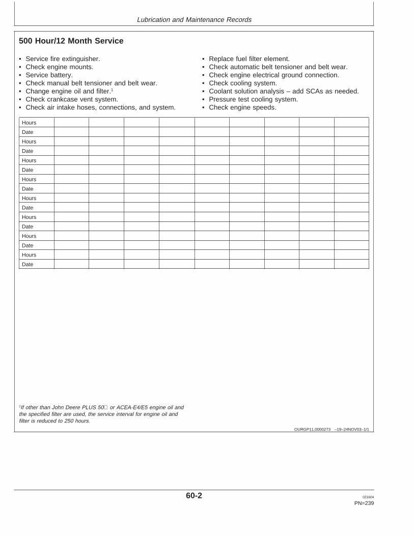
Lubrication and Maintenance Records
OURGP11,0000273 –19–24NOV03–1/1
500 Hour/12 Month Service
• Service fire extinguisher.• Check engine mounts.• Service battery.• Check manual belt tensioner and belt wear.• Change engine oil and filter.1
• Check crankcase vent system.• Check air intake hoses, connections, and system.
• Replace fuel filter element.• Check automatic belt tensioner and belt wear.• Check engine electrical ground connection.• Check cooling system.• Coolant solution analysis – add SCAs as needed.• Pressure test cooling system.• Check engine speeds.
Hours
Date
Hours
Date
Hours
Date
Hours
Date
Hours
Date
Hours
Date
Hours
Date
Hours
Date
1If other than John Deere PLUS 50 or ACEA-E4/E5 engine oil andthe specified filter are used, the service interval for engine oil andfilter is reduced to 250 hours.
60-2 021604
PN=239
https://www.truck-manuals.net/
Lubrication and Maintenance Records
RG,RG34710,5625 –19–05MAR03–1/1
2000 Hour/24 Month Service
• Check crankshaft vibration damper (6-cylinder only).• Flush and refill cooling system.1
• Test thermostats.
• Check and adjust valve clearance.• Test glow plugs (4045HF475, 6068HF475)
Hours
Date
Hours
Date
Hours
Date
Hours
Date
Hours
Date
Hours
Date
Hours
Date
Hours
Date
1If John Deere COOL-GARD is used, the flushing interval may beextended to 3000 hours, or 36 months. If John Deere COOL-GARDis used and the coolant is tested annually AND additives arereplenished as needed by adding a supplemental coolant additive,the flushing interval may be extended to 5000 hours or 60 months,whichever occurs first.
60-3 021604
PN=240
https://www.truck-manuals.net/
Lubrication and Maintenance Records
RG,RG34710,5627 –19–11MAR03–1/1
Service as Required
• Add coolant• Service air cleaner.• Replace poly-vee belts.• Check fuses• Check air compressor (if equipped)• Bleed fuel system
Hours
Date
Hours
Date
Hours
Date
Hours
Date
Hours
Date
Hours
Date
Hours
Date
Hours
Date
60-4 021604
PN=241
https://www.truck-manuals.net/
Emission System Warranty
RG,RG34710,7629 –19–30JUN97–1/1
U.S. EPA Emissions Control Warranty Statement
Emissions control-related parts and components arewarranted by John Deere for five years or 3000 hoursof operation, whichever occurs first. John Deere furtherwarrants that the engine covered by this warranty wasdesigned, built, and equipped so as to conform at thetime of sale with all U.S. emissions standards at thetime of manufacture, and that it is free of defects inmaterials and workmanship which would cause it notto meet these standards within the period of five yearsor 3000 hours of operation, whichever occurs first.
Warranties stated in this manual refer only toemissions-related parts and components of yourengine. The complete engine warranty, lessemissions-related parts and components, is providedseparately as the “John Deere New Off-HighwayEngine Warranty”.
65-1 021604
PN=242
https://www.truck-manuals.net/
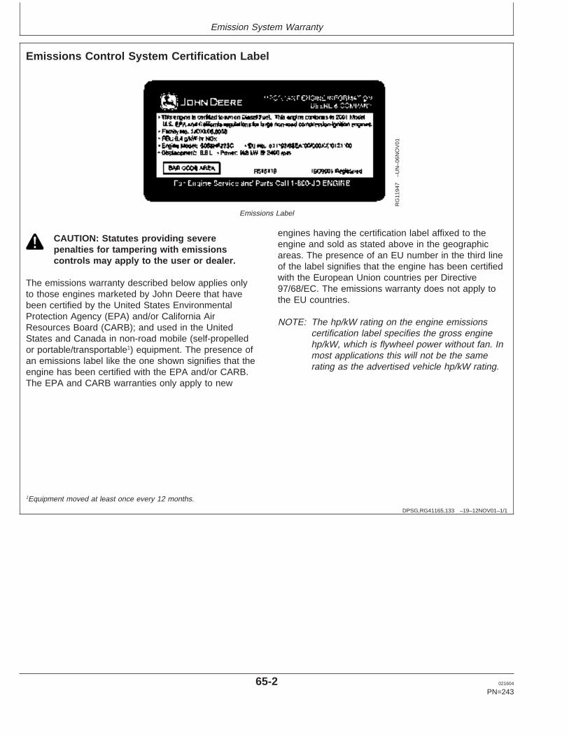
Emission System Warranty
DPSG,RG41165,133 –19–12NOV01–1/1
Emissions Control System Certification Label
RG
1194
7–U
N–0
6NO
V01
Emissions Label
CAUTION: Statutes providing severepenalties for tampering with emissionscontrols may apply to the user or dealer.
The emissions warranty described below applies onlyto those engines marketed by John Deere that havebeen certified by the United States EnvironmentalProtection Agency (EPA) and/or California AirResources Board (CARB); and used in the UnitedStates and Canada in non-road mobile (self-propelledor portable/transportable1) equipment. The presence ofan emissions label like the one shown signifies that theengine has been certified with the EPA and/or CARB.The EPA and CARB warranties only apply to new
engines having the certification label affixed to theengine and sold as stated above in the geographicareas. The presence of an EU number in the third lineof the label signifies that the engine has been certifiedwith the European Union countries per Directive97/68/EC. The emissions warranty does not apply tothe EU countries.
NOTE: The hp/kW rating on the engine emissionscertification label specifies the gross enginehp/kW, which is flywheel power without fan. Inmost applications this will not be the samerating as the advertised vehicle hp/kW rating.
1Equipment moved at least once every 12 months.
65-2 021604
PN=243
https://www.truck-manuals.net/
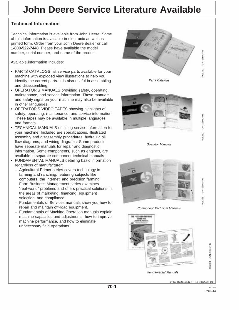
John Deere Service Literature Available
DPSG,RG41165,134 –19–10JUL00–1/1
Technical Information
RG
9262
–UN
–16M
AR
98
Parts Catalogs
RG
9260
–UN
–16M
AR
98
Operator Manuals
RG
9261
–UN
–16M
AR
98
Component Technical ManualsT
S16
63–U
N–1
0OC
T97
Fundamental Manuals
Technical information is available from John Deere. Someof this information is available in electronic as well asprinted form. Order from your John Deere dealer or call1-800-522-7448. Please have available the modelnumber, serial number, and name of the product.
Available information includes:
• PARTS CATALOGS list service parts available for yourmachine with exploded view illustrations to help youidentify the correct parts. It is also useful in assemblingand disassembling.
• OPERATOR’S MANUALS providing safety, operating,maintenance, and service information. These manualsand safety signs on your machine may also be availablein other languages.
• OPERATOR’S VIDEO TAPES showing highlights ofsafety, operating, maintenance, and service information.These tapes may be available in multiple languagesand formats.
• TECHNICAL MANUALS outlining service information foryour machine. Included are specifications, illustratedassembly and disassembly procedures, hydraulic oilflow diagrams, and wiring diagrams. Some productshave separate manuals for repair and diagnosticinformation. Some components, such as engines, areavailable in separate component technical manuals
• FUNDAMENTAL MANUALS detailing basic informationregardless of manufacturer:– Agricultural Primer series covers technology in
farming and ranching, featuring subjects likecomputers, the Internet, and precision farming.
– Farm Business Management series examines“real-world” problems and offers practical solutions inthe areas of marketing, financing, equipmentselection, and compliance.
– Fundamentals of Services manuals show you how torepair and maintain off-road equipment.
– Fundamentals of Machine Operation manuals explainmachine capacities and adjustments, how to improvemachine performance, and how to eliminateunnecessary field operations.
70-1 021604
PN=244
https://www.truck-manuals.net/
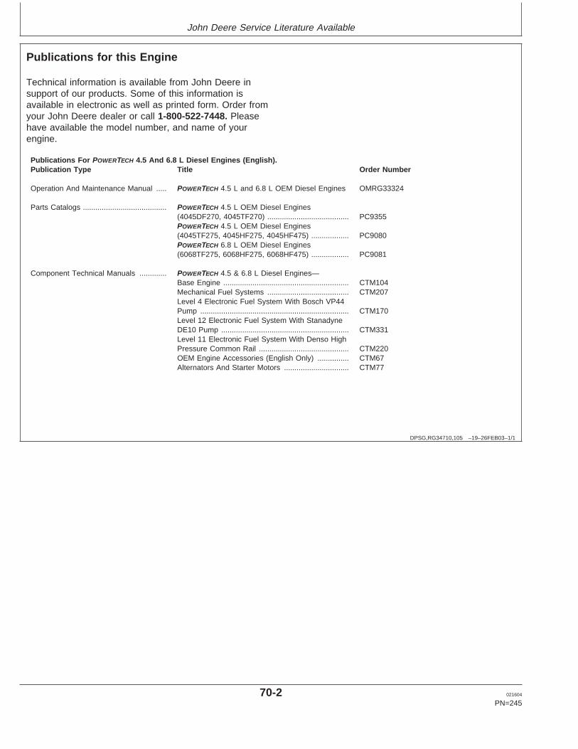
John Deere Service Literature Available
DPSG,RG34710,105 –19–26FEB03–1/1
Publications for this Engine
Technical information is available from John Deere insupport of our products. Some of this information isavailable in electronic as well as printed form. Order fromyour John Deere dealer or call 1-800-522-7448. Pleasehave available the model number, and name of yourengine.
Publications For POWERTECH 4.5 And 6.8 L Diesel Engines (English).Publication Type Title Order Number
Operation And Maintenance Manual ..... POWERTECH 4.5 L and 6.8 L OEM Diesel Engines OMRG33324
Parts Catalogs ........................................ POWERTECH 4.5 L OEM Diesel Engines(4045DF270, 4045TF270) ....................................... PC9355POWERTECH 4.5 L OEM Diesel Engines(4045TF275, 4045HF275, 4045HF475) .................. PC9080POWERTECH 6.8 L OEM Diesel Engines(6068TF275, 6068HF275, 6068HF475) .................. PC9081
Component Technical Manuals ............. POWERTECH 4.5 & 6.8 L Diesel Engines—Base Engine ............................................................ CTM104Mechanical Fuel Systems ....................................... CTM207Level 4 Electronic Fuel System With Bosch VP44Pump ....................................................................... CTM170Level 12 Electronic Fuel System With StanadyneDE10 Pump ............................................................. CTM331Level 11 Electronic Fuel System With Denso HighPressure Common Rail ........................................... CTM220OEM Engine Accessories (English Only) ............... CTM67Alternators And Starter Motors ............................... CTM77
70-2 021604
PN=245
https://www.truck-manuals.net/
John Deere Service Literature Available
70-3 021604
PN=246
https://www.truck-manuals.net/
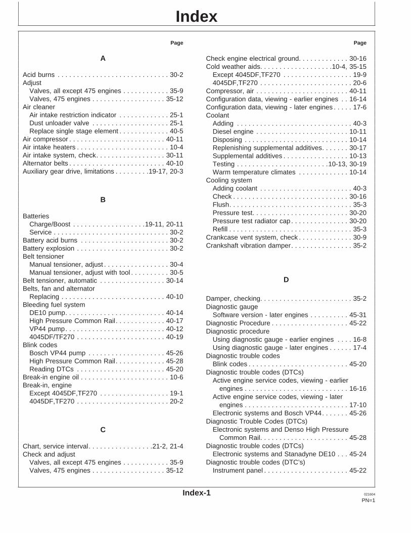
IndexPage Page
A Check engine electrical ground. . . . . . . . . . . . . 30-16Cold weather aids. . . . . . . . . . . . . . . . . . .10-4, 35-15
Except 4045DF,TF270 . . . . . . . . . . . . . . . . . . 19-9Acid burns . . . . . . . . . . . . . . . . . . . . . . . . . . . . . 30-2Adjust 4045DF,TF270 . . . . . . . . . . . . . . . . . . . . . . . . 20-6
Valves, all except 475 engines . . . . . . . . . . . . 35-9 Compressor, air . . . . . . . . . . . . . . . . . . . . . . . . 40-11Valves, 475 engines . . . . . . . . . . . . . . . . . . . 35-12 Configuration data, viewing - earlier engines . . 16-14
Air cleaner Configuration data, viewing - later engines . . . . . 17-6Air intake restriction indicator . . . . . . . . . . . . . 25-1 CoolantDust unloader valve . . . . . . . . . . . . . . . . . . . . 25-1 Adding . . . . . . . . . . . . . . . . . . . . . . . . . . . . . . 40-3Replace single stage element . . . . . . . . . . . . . 40-5 Diesel engine . . . . . . . . . . . . . . . . . . . . . . . . 10-11
Air compressor . . . . . . . . . . . . . . . . . . . . . . . . . 40-11 Disposing . . . . . . . . . . . . . . . . . . . . . . . . . . . 10-14Air intake heaters . . . . . . . . . . . . . . . . . . . . . . . . 10-4 Replenishing supplemental additives. . . . . . . 30-17Air intake system, check. . . . . . . . . . . . . . . . . . 30-11 Supplemental additives . . . . . . . . . . . . . . . . . 10-13Alternator belts . . . . . . . . . . . . . . . . . . . . . . . . . 40-10 Testing . . . . . . . . . . . . . . . . . . . . . . . .10-13, 30-19Auxiliary gear drive, limitations . . . . . . . . .19-17, 20-3 Warm temperature climates . . . . . . . . . . . . . 10-14
Cooling systemAdding coolant . . . . . . . . . . . . . . . . . . . . . . . . 40-3Check . . . . . . . . . . . . . . . . . . . . . . . . . . . . . . 30-16BFlush. . . . . . . . . . . . . . . . . . . . . . . . . . . . . . . . 35-3Pressure test. . . . . . . . . . . . . . . . . . . . . . . . . 30-20BatteriesPressure test radiator cap . . . . . . . . . . . . . . . 30-20Charge/Boost . . . . . . . . . . . . . . . . . . .19-11, 20-11Refill . . . . . . . . . . . . . . . . . . . . . . . . . . . . . . . . 35-3Service . . . . . . . . . . . . . . . . . . . . . . . . . . . . . . 30-2
Crankcase vent system, check . . . . . . . . . . . . . . 30-9Battery acid burns . . . . . . . . . . . . . . . . . . . . . . . 30-2Crankshaft vibration damper. . . . . . . . . . . . . . . . 35-2Battery explosion . . . . . . . . . . . . . . . . . . . . . . . . 30-2
Belt tensionerManual tensioner, adjust . . . . . . . . . . . . . . . . . 30-4Manual tensioner, adjust with tool . . . . . . . . . . 30-5
DBelt tensioner, automatic . . . . . . . . . . . . . . . . . 30-14Belts, fan and alternator
Replacing . . . . . . . . . . . . . . . . . . . . . . . . . . . 40-10 Damper, checking. . . . . . . . . . . . . . . . . . . . . . . . 35-2Bleeding fuel system Diagnostic gauge
DE10 pump. . . . . . . . . . . . . . . . . . . . . . . . . . 40-14 Software version - later engines . . . . . . . . . . 45-31High Pressure Common Rail. . . . . . . . . . . . . 40-17 Diagnostic Procedure . . . . . . . . . . . . . . . . . . . . 45-22VP44 pump. . . . . . . . . . . . . . . . . . . . . . . . . . 40-12 Diagnostic procedure4045DF/TF270 . . . . . . . . . . . . . . . . . . . . . . . 40-19 Using diagnostic gauge - earlier engines . . . . 16-8
Blink codes Using diagnostic gauge - later engines . . . . . . 17-4Bosch VP44 pump . . . . . . . . . . . . . . . . . . . . 45-26 Diagnostic trouble codesHigh Pressure Common Rail. . . . . . . . . . . . . 45-28 Blink codes . . . . . . . . . . . . . . . . . . . . . . . . . . 45-20Reading DTCs . . . . . . . . . . . . . . . . . . . . . . . 45-20 Diagnostic trouble codes (DTCs)
Break-in engine oil . . . . . . . . . . . . . . . . . . . . . . . 10-6 Active engine service codes, viewing - earlierBreak-in, engine engines . . . . . . . . . . . . . . . . . . . . . . . . . . . 16-16
Except 4045DF,TF270 . . . . . . . . . . . . . . . . . . 19-1 Active engine service codes, viewing - later4045DF,TF270 . . . . . . . . . . . . . . . . . . . . . . . . 20-2 engines . . . . . . . . . . . . . . . . . . . . . . . . . . . 17-10
Electronic systems and Bosch VP44. . . . . . . 45-26Diagnostic Trouble Codes (DTCs)
Electronic systems and Denso High PressureCCommon Rail. . . . . . . . . . . . . . . . . . . . . . . 45-28
Diagnostic trouble codes (DTCs)Chart, service interval. . . . . . . . . . . . . . . . .21-2, 21-4Electronic systems and Stanadyne DE10 . . . 45-24Check and adjust
Diagnostic trouble codes (DTC’s)Valves, all except 475 engines . . . . . . . . . . . . 35-9Valves, 475 engines . . . . . . . . . . . . . . . . . . . 35-12 Instrument panel . . . . . . . . . . . . . . . . . . . . . . 45-22
Index-1 021604
PN=1
https://www.truck-manuals.net/
Index
Page Page
Diagnostic trouble codes (DTCs) Engine wiring layoutWith Bosch VP44 pump . . . . . . . . . . . . . . . . . 45-4Stored service codes, viewing - earlierWith Denso High Pressure Common Rail . . . . 45-5engines . . . . . . . . . . . . . . . . . . . . . . . . . . . 16-17With Stanadyne DE10 pump. . . . . . . . . . . . . . 45-3Stored service codes, viewing - later
Error Codes . . . . . . . . . . . . . . . . . . . . . . . . . . . 45-30engines . . . . . . . . . . . . . . . . . . . . . . . . . . . . 17-8Diesel engine oil . . . . . . . . . . . . . . . . . . . . . . . . . 10-7Diesel fuel . . . . . . . . . . . . . . . . . . . . . . . . .10-1, 10-3DTCs (Diagnostic Trouble Codes)
FView active service codes - earlierengines . . . . . . . . . . . . . . . . . . . . . . . . . . . 16-16
Fan belts . . . . . . . . . . . . . . . . . . . . . . . . . . . . . 40-10View active service codes - later engines . . . 17-10Filter, replaceView stored service codes - earlier
Fuel . . . . . . . . . . . . . . . . . . . . . . . . . . . . . . . 30-12engines . . . . . . . . . . . . . . . . . . . . . . . . . . . 16-17Oil . . . . . . . . . . . . . . . . . . . . . . . . . . . . . . . . . . 30-7View stored service codes - later engines . . . . 17-8
Fire extinguisher, service . . . . . . . . . . . . . . . . . . 30-1Fuel
Diesel . . . . . . . . . . . . . . . . . . . . . . . . . . .10-1, 10-3Handling and storing . . . . . . . . . . . . . . . . . . . . 10-2ELubricity . . . . . . . . . . . . . . . . . . . . . . . . . . . . . 10-1
Fuel filterEmissions Checking. . . . . . . . . . . . . . . . . . . . . . . . . . . . . 25-1
EPA Statement . . . . . . . . . . . . . . . . . . . . . . . . 65-1 Draining water. . . . . . . . . . . . . . . . . . . . . . . . . 25-1Engine Replace . . . . . . . . . . . . . . . . . . . . . . . . . . . . 30-12
Adjust speed. . . . . . . . . . . . . . . . . . . . . . . . . 30-21 Fuel injection pump model number. . . . . . . . . . . 01-5Break-in, except 4045DF,TF270 . . . . . . . . . . . 19-1 Fuel systemBreak-in, 4045DF,TF270. . . . . . . . . . . . . . . . . 20-2 Bleeding (DE10 pump) . . . . . . . . . . . . . . . . . 40-14Changing speed . . . . . . . . . . . . . . . . . . . . . . 19-13 Bleeding (High Pressure Common Rail) . . . . 40-17Check electrical ground. . . . . . . . . . . . . . . . . 30-16 Bleeding (VP44 pump) . . . . . . . . . . . . . . . . . 40-12Idling. . . . . . . . . . . . . . . . . . . . . . . . . . .19-12, 20-9 Bleeding (4045DF/TF270) . . . . . . . . . . . . . . . 40-19Operation, except 4045DF,TF270 . . . . . . . . . . 19-7 Fuses, checking . . . . . . . . . . . . . . . . . . . . . . . . 40-11Operation, 4045DF,TF270. . . . . . . . . . . . . . . . 20-1Option codes. . . . . . . . . . . . . . . . . . . . . . . . . . 01-3Serial number . . . . . . . . . . . . . . . . . . . . . . . . . 01-1Starting, except 4045DF,TF270 engine . . . . . . 19-4 GStarting, 4045DF,TF270 engine . . . . . . . . . . . 20-4Stopping, except 4045DF,TF270. . . . . . . . . . 19-16 GaugesStopping, 4045DF,TF270 . . . . . . . . . . . . . . . 20-10 Except 4045DF,TF270 . . . . . . . . . . . . . . . . . . 19-8Troubleshooting . . . . . . . . . . . . . . . . . . . . . . 45-10 4045DF,TF270 . . . . . . . . . . . . . . . . . . . . . . . . 20-8Warming, except 4045DF,TF270. . . . . . . . . . . 19-8 Generator (Standby) Applications . . . . . . . . . . . . 21-4Warming, 4045DF,TF270 . . . . . . . . . . . . . . . . 20-8 Glow plugs
Engine coolant Test, 475 engines . . . . . . . . . . . . . . . . . . . . . 35-15Disposing of . . . . . . . . . . . . . . . . . . . . . . . . . 10-14 Grease
Engine mounts, check . . . . . . . . . . . . . . . . . . . . 30-1 Extreme pressure and multipurpose . . . . . . . 10-10Engine oil
Break-In . . . . . . . . . . . . . . . . . . . . . . . . . . . . . 10-6Change . . . . . . . . . . . . . . . . . . . . . . . . . . . . . . 30-7
IDiesel . . . . . . . . . . . . . . . . . . . . . . . . . . . . . . . 10-7Extended Service Intervals . . . . . . . . . . . . . . . 10-8
Engine speed Idling engine. . . . . . . . . . . . . . . . . . . . . . .19-12, 20-9Changing . . . . . . . . . . . . . . . . . . . . . . . . . . . 19-13 Instrument panels
Engine wiring diagram Adjust backlighting - later engines. . . . . . . . . 17-13Adjust contrast - later engines. . . . . . . . . . . . 17-15W/electronic instrument panel . . . . . . . . . . . . . 45-6
Index-2 021604
PN=2
https://www.truck-manuals.net/
Index
Page Page
Changing units of measure - earlier Fill quantity . . . . . . . . . . . . . . . . . . . . . . . . . . . 55-6Filler locations. . . . . . . . . . . . . . . . . . . . . . . . . 25-1engines . . . . . . . . . . . . . . . . . . . . . . . . . . . 16-12
Changing units of measure - later engines . . 17-17 Oil filter, change . . . . . . . . . . . . . . . . . . . . . . . . . 30-7Operating engineComponent function - earlier engines . . . . . . . 16-1
Component function - later engines. . . . . . . . . 17-1 Break-in, except 4045DF,TF270 . . . . . . . . . . . 19-1Break-in, 4045DF,TF270. . . . . . . . . . . . . . . . . 20-2identification . . . . . . . . . . . . . . . . . . . . . . . . . . 15-1
Main menu navigation - later engines . . . . . . . 17-5 Cold weather. . . . . . . . . . . . . . . . . . . . . . . . . . 10-4Cold weather, except 4045DF,TF270 . . . . . . . 19-9Setup 1-up display - later engines. . . . . . . . . 17-20
Setup 4-up display - later engines. . . . . . . . . 17-26 Cold weather, 4045DF,TF270 . . . . . . . . . . . . . 20-6Normal operation, except 4045DF,TF270 . . . . 19-7Shutdown codes - later engines . . . . . . . . . . 17-12
Touch switches - earlier engines. . . . . . . . . . 16-10 Normal operation, 4045DF,TF270 . . . . . . . . . . 20-1Option codes . . . . . . . . . . . . . . . . . . . . . . . . . . . 01-3Using diagnostic gauge - earlier engines . . . . 16-8
Using diagnostic gauge - later engines . . . . . . 17-4Viewing active service codes - earlier
engines . . . . . . . . . . . . . . . . . . . . . . . . . . . 16-16PViewing active service codes - later
engines . . . . . . . . . . . . . . . . . . . . . . . . . . . 17-10Poly-vee beltsViewing configuration data - earlier
Replace . . . . . . . . . . . . . . . . . . . . . . . . . . . . 40-10engines . . . . . . . . . . . . . . . . . . . . . . . . . . . 16-14Power ratings . . . . . . . . . . . . . . . . . . . . . . . . . . . 55-3Viewing configuration data - later engines. . . . 17-6Precautions for welding on engines equippedViewing stored service codes - earlier
w/ECU . . . . . . . . . . . . . . . . . . . . . . . . . . . . . . 45-2engines . . . . . . . . . . . . . . . . . . . . . . . . . . . 16-17Viewing stored service codes - later
engines . . . . . . . . . . . . . . . . . . . . . . . . . . . . 17-8Intermittent fault diagnostics . . . . . . . . . . . . . . . 45-31 R
Radiator cap testing . . . . . . . . . . . . . . . . . . . . . 30-20L Radiator shutters . . . . . . . . . . . . . . . . . . . . . . . . 10-4
RecordkeepingListing of DTCs. . . . . . . . . . . . . . 45-24, 45-26, 45-28 Engine option codes . . . . . . . . . . . . . . . . . . . . 01-3Lubricant Engine serial number . . . . . . . . . . . . . . . . . . . 01-1
Mixing . . . . . . . . . . . . . . . . . . . . . . . . . . . . . . . 10-8 Injection pump model number . . . . . . . . . . . . . 01-5Storage . . . . . . . . . . . . . . . . . . . . . . . . . . . . . 10-10
Lubrication and MaintenanceService Interval Chart . . . . . . . . . . . . . . .21-2, 21-4
Lubricity of diesel fuel. . . . . . . . . . . . . . . . . . . . . 10-1 S
Serial numberEngine . . . . . . . . . . . . . . . . . . . . . . . . . . . . . . 01-1MFuel injection pump. . . . . . . . . . . . . . . . . . . . . 01-5
Maintenance interval chart ServiceGenerator (Standby) applications . . . . . . . . . . 21-4 Battery . . . . . . . . . . . . . . . . . . . . . . . . . . . . . . 30-2Standard industrial applications. . . . . . . . . . . . 21-2 Fire extinguisher . . . . . . . . . . . . . . . . . . . . . . . 30-1
Manual belt tensioner . . . . . . . . . . . . . . . . . . . . . 30-4 Intervals . . . . . . . . . . . . . . . . . . . . . . . . .21-2, 21-4Manual belt tensioner - using belt tension tool . . 30-5 Service IntervalsMixing lubricants. . . . . . . . . . . . . . . . . . . . . . . . . 10-8 Extended Diesel Engine Oil . . . . . . . . . . . . . . 10-8
Service intervalsGeneral information. . . . . . . . . . . . . . . . . . . . . 21-1
Service literature . . . . . . . . . . . . . . . . . . . . . . . . 70-2OSpecifications
Battery capabilities . . . . . . . . . . . . . . . . . . . . . 30-2OilDipstick . . . . . . . . . . . . . . . . . . . . . . . . . . . . . . 25-1 Belt tensioner . . . . . . . . . . . . . . . . . . . . . . . . 30-14
Index-3 021604
PN=3
https://www.truck-manuals.net/
Index
Page Page
Damper. . . . . . . . . . . . . . . . . . . . . . . . . . . . . . 35-2 475 engines. . . . . . . . . . . . . . . . . . . . . . . . 35-12Vibration damper . . . . . . . . . . . . . . . . . . . . . . . . 35-2Engine crankcase oil fill . . . . . . . . . . . . . . . . . 55-6
Fuel injection pump and power ratings . . . . . . 55-3General OEM . . . . . . . . . . . . . . . . . . . . . . . . . 55-1
Standby power units . . . . . . . . . . . . . . . . .19-17, 20-4 WStarting engine, except 4045DF,TF270
engine. . . . . . . . . . . . . . . . . . . . . . . . . . . . . . . 19-4Warming engine, except 4045DF,TF270 . . . . . . 19-8
Starting engine, 4045DF,TF270 engine . . . . . . . 20-4Warming engine, 4045DF,TF270 . . . . . . . . . . . . 20-8
Stopping engine, except 4045DF,TF270. . . . . . 19-16Warranty
Stopping engine, 4045DF,TF270 . . . . . . . . . . . 20-10Emission System . . . . . . . . . . . . . . . . . . . . . . 65-2
StorageWinterfronts . . . . . . . . . . . . . . . . . . . . . . . . . . . . 10-4
Guidelines. . . . . . . . . . . . . . . . . . . . . . . . . . . . 50-1Wiring diagrams, engine
Long term . . . . . . . . . . . . . . . . . . . . . . . . . . . . 50-2Engines w/electronic instrument panel . . . . . . 45-6
Removing from . . . . . . . . . . . . . . . . . . . . . . . . 50-3Wiring harness
Storing fuel . . . . . . . . . . . . . . . . . . . . . . . . . . . . . 10-2With Bosch VP44 pump . . . . . . . . . . . . . . . . . 45-4
Storing lubricants . . . . . . . . . . . . . . . . . . . . . . . 10-10With Denso High Pressure Common Rail . . . . 45-5
Supplemental coolant additivesWith Stanadyne DE10 pump. . . . . . . . . . . . . . 45-3
Replenishing . . . . . . . . . . . . . . . . . . . . . . . . . 30-17
T
Tensioner, beltAutomatic . . . . . . . . . . . . . . . . . . . . . . . . . . . 30-14Manual . . . . . . . . . . . . . . . . . . . . . . . . . . . . . . 30-4
ThermostatInstall . . . . . . . . . . . . . . . . . . . . . . . . . . . . . . . 35-6Remove . . . . . . . . . . . . . . . . . . . . . . . . . . . . . 35-6Test opening temperature . . . . . . . . . . . . . . . . 35-6
Touch switches - earlier engines . . . . . . . . . . . 16-10Trouble codes
Electronic systems and Bosch VP44. . . . . . . 45-26Electronic systems and Denso High Pressure
Common Rail. . . . . . . . . . . . . . . . . . . . . . . 45-28Electronic systems and Stanadyne DE10 . . . 45-24
TroubleshootingGeneral, engine . . . . . . . . . . . . . . . . . . . . . . 45-10
U
Units of measure, changing - earlier engines . . 16-12Units of measure, changing - later engines . . . 17-17
V
ValvesClearance, check and adjust
All except 475 engines . . . . . . . . . . . . . . . . 35-9
Index-4 021604
PN=4
https://www.truck-manuals.net/