Embed Size (px)
Citation preview

USE AND MAINTENANCE MANUAL
MISTBLOWERS
MOUNTED MISTBLOWERS
serie EXPO - CLIO - KAMBA - VENUS - DEVIL - SIRIO - EOLO - AP
Read this manual carefullybefore use.
USA
04/2010
ISO
Color code

2 unigreen
Summary
1 USING AND KEEPING THE USE AND MAINTENANCE MANUAL .................... 4
1.1 COMPOSITION OF THE MANUAL ....................................................................................... 41.2 GUARANTEE ....................................................................................................................... 41.3 PRODUCT RESPONSIBILITY .............................................................................................. 41.4 WARNING SIGNS IN THE MANUAL AND ON THE MACHINE ............................................. 42 SAFETY REGULATIONS AND RESIDUAL RISKS .............................................. 5
2.1 INTENDED USE ................................................................................................................... 62.2 PROHIBITED USE ............................................................................................................... 62.3 USING CHEMICAL PRODUCTS .......................................................................................... 62.3.1 REGULATIONS FOR THE USE OF CHEMICAL PRODUCTS ............................................... 6
2.4 RECOMMENDATIONS ......................................................................................................... 62.4.1 TAKING PRECAUTIONS AGAINST FIRE HAZARDS ........................................................... 7
2.5 WEATHER CONDITIONS ..................................................................................................... 72.6 MACHINES DESIGNED TO BE USED ONLY WITH CLEAN WATER .................................... 72.7 DRIVING ON THE ROAD ..................................................................................................... 73 CHARACTERISTICS AND SPECIFICATIONS ..................................................... 7
3.1 TABLES OF FITTINGS ALLOWED ....................................................................................... 73.2 NOISE LEVEL OF THE MACHINE ....................................................................................... 83.3 STANDARDS OF REFERENCE: ........................................................................................... 84 USER’S INSTRUCTIONS ....................................................................................... 8
4.1 DESCRIPTION OF THE MACHINE ...................................................................................... 84.1.1 WORK STATIONS ................................................................................................................ 84.1.2 HAND WASHING TANKS ...................................................................................................... 9
4.2 PRELIMINARY CHECKS...................................................................................................... 94.3 TRANSPORTING AND MOVING THE MACHINE ................................................................. 94.3.1 TOWED ATOMISERS ........................................................................................................... 9
4.4 TRACTOR COUPLING ........................................................................................................104.4.1 THREE-POINT COUPLING .................................................................................................104.4.2 HYDRAULIC CONNECTION TO THE DISTRIBUTORS ........................................................10
4.5 CARDAN SHAFT .................................................................................................................114.6 PUMP..................................................................................................................................114.7 SUCTION FILTER ...............................................................................................................114.8 PRESSURE REGULATOR ...................................................................................................124.8.1 COMPONENTS OF THE PRESSURE REGULATOR ...........................................................124.8.2 GENERAL INSTRUCTIONS ................................................................................................12
4.9 DELIVERY FILTERS (ONLY EQUIPPED MODELS) ............................................................134.10 FILLING THE TANK .............................................................................................................144.11 TEST WITH CLEAN WATER ................................................................................................144.12 MIXING ...............................................................................................................................144.12.1 MANUAL PREMIXING .........................................................................................................154.12.2 PREMIXER ON COVER (OPTIONAL): ................................................................................15
4.13 WASHING THE ATOMISER .................................................................................................154.13.1 CIRCUIT WASHER AND TANK WASHER ............................................................................155 BLOWER GROUP ................................................................................................ 16
5.1 AXIAL BLOWER GROUP WITH PULLEY ............................................................................165.2 AXIAL BLOWER GROUP WITH MULTIPLIER .....................................................................165.3 BLOWER GROUP WITH FRONT SUCTION ........................................................................175.3.1 SINGLE-SIDE BLOWER GROUP ........................................................................................17
5.4 AXIAL ROTOR .....................................................................................................................175.5 CLUTCH ..............................................................................................................................185.6 OPTIONAL DEFLECTORS AND ACCESSORIES ...............................................................185.7 CANNON BLOWER GROUP ...............................................................................................185.7.1 MANUALLY INCLINABILE HEAD.........................................................................................185.7.2 HYDRAULIC DRIVEN HEADS .............................................................................................185.7.3 HYDRAULIC DRIVES ..........................................................................................................185.7.4 OIL FEED FROM TRACTOR ...............................................................................................186 SPRAYING ............................................................................................................ 19
6.1 DESCRIPTION OF TYPE OF JETS ....................................................................................196.2 DESCRIPTION OF TYPE OF NOZZLES .............................................................................196.2.1 NORMAL VOLUME CONICAL NOZZLES (OVER 500L/HA) .................................................196.2.2 LOW VOLUME CONICAL NOZZLES (150-500L/HA) ............................................................196.2.3 ANTI-DRIFT NOZZLES .......................................................................................................19

unigreen 3
6.3 CALIBRATING AXIAL FAN ATOMISERS .............................................................................206.4 CALIBRATING CANNON ATOMISERS ................................................................................206.4.1 TREATMENTS ON TALL PLANTS .......................................................................................206.4.2 TREATMENTS ON HERBACEOUS CULTIVATIONS ...........................................................217 HAND LANCES .................................................................................................... 21
8 MAINTENANCE .................................................................................................... 22
8.1 PROGRAMMED MAINTENANCE........................................................................................228.2 ROUTINE MAINTENANCE ..................................................................................................228.2.1 CLEANING THE NOZZLES .................................................................................................228.2.2 LUBRICATION .....................................................................................................................228.2.3 MULTIPLIER LUBRICATION................................................................................................22
8.3 EXTRAORDINARY MAINTENANCE ...................................................................................228.4 REPAIRS .............................................................................................................................238.5 STORAGE IN A WAREHOUSE AND TRANSPORTATION ...................................................238.6 PUTTING BACK INTO SERVICE AFTER WINTER LAYUP .................................................238.7 DEMOLITION AND DISPOSAL ...........................................................................................238.7.1 MATERIALS FOR DEMOLITION .........................................................................................238.7.2 INDICATIONS FOR A SUITABLE TREATMENT OF WASTE................................................238.7.3 ELECTRICAL AND ELECTRONIC APPARATUS WASTE (EEAW) .......................................23
TABLES FOR CALIBRATING ATOMISERS Ø500-600 ..................................... 25
TABLES FOR CALIBRATING ATOMISERS Ø600-650 ..................................... 26
TABLES FOR CALIBRATING ATOMISERS Ø700-750 ..................................... 27
TABLES FOR CALIBRATING ATOMISERS Ø800............................................. 28
TABLES FOR CALIBRATING ATOMISERS Ø900............................................. 29
TABLES FOR CALIBRATING ATOMISERS Ø650 TGZ .................................... 30
TABLES FOR CALIBRATING ATOMISERS Ø800 TGZ .................................... 30
TABLES FOR CALIBRATING CANNONS Ø450 ................................................ 31
TABLES FOR CALIBRATING CANNONS Ø400-455 ......................................... 32
TABLES FOR CALIBRATING CANNONS Ø400-455 ......................................... 33
TAB. 1-3 TABLES OF DELIVERY OF NOZZLES FOR ATOMISERS ................................ 34
TAB. 4-5 TABLES OF DELIVERY OF NOZZLES FOR HAND LANCES .......................... 35
TAB. 7 TABLE OF PROGRAMMED MAINTENANCE .................................................... 36
TAB. 8 PROBLEMS, CAUSES AND SOLUTIONS .......................................................... 36
TAB.14A ALLOWED FITTINGS ........................................................................................... 37
TAB.15A ALLOWED FITTINGS ........................................................................................... 38
TAB.16A ALLOWED FITTINGS ........................................................................................... 39

4 unigreen
Thank you for having chosen UNIGREEN.The product you purchased has been designed and built with the greatest atten-tion to the safety of the operator and the environment, nevertheless there arestill some residual risks due to the nature of the product used.For this reason we recommend reading all of this manual to avoid making mis-takes in the first period of use and to get the most out of the working life of theatomiser in time, doing the programmed maintenance at regular intervals.
1 USING AND KEEPING THE USE AND MAINTENANCE MANUAL
The manual is an integral part of the machine and should be kept in a safeplace where it can be reached easily for consultation.
1.1 COMPOSITION OF THE MANUAL
This manual consists of various parts to make it easier to consult by subjectand to avoid repetitions; the following are part of the manual:a) pump handbookb) pressure regulator handbook (manual or electric)c) spraying computer handbook (if fitted)d) optional accessories handbooks (marker, premix, cardan shaft, etc.)UNIGREEN reserves the right to make changes to the manual without priorwarning and the normal printing cycles may vary slightly.
1.2 GUARANTEE
The enclosed card indicates the conditions of the UNIGREEN guarantee. TheUNIGREEN guarantee covers the repair or replacement of parts considered manu-facturing flaws, according to the unquestionable judgement of UNIGREEN, onlyafter the authorised agent for that zone has verified the fault.Ambit of the guarantee
The guarantee doesn’t cover cases of normal wear, negligent use, poor mainte-nance and/or improper use.The following materials subject to normal wear are not covered by the
guarantee: gaskets and seals, diaphragms, seal rings, tubes and pipes, noz-zles, pressure gauges, oil, tyres, friction material of the clutches.Evident cases of negligence include:
work speed over that indicated in the spraying tables in the handbook (or toohigh for the conditions of the terrain), power-takeoff speed over 540 rpm andanything else indicated in the Use and Maintenance Manual.Maintenance:
The guarantee is void if the maintenance indicated in the tables in this manualisn’t respected, regarding the period and deadline of the interventions, washingthe machine and the circuit at the end of the treatment.Improper use:
The use the UNIGREEN machines are designed for is indicated in this manual,any other use is forbidden and makes the guarantee void.
1.3 PRODUCT RESPONSIBILITY
UNIGREEN spa is not responsible if:a) During the working life of the machine the normal maintenance operationsaren’t performed and documented as indicated in this handbook, in the en-closed handbooks of the pumps-motors-regulators-etc. and in any case as iscustomary for the normal maintenance of mechanical machinery.b) The machine is equipped with non original accessories or components orparts that aren’t acknowledged by UNIGREEN as their own.c) The machine is equipped with original accessories or components that areunsuitable in the measurements, weight or version for the same.Please consult the page of available and recommended fittings.d) Not following the instructions in the manual whether totally or partially.e) Modifications made to the machine that haven’t been authorised byUNIGREEN.
1.4 WARNING SIGNS IN THE MANUAL AND ON THE MACHINE
Below you will find all of the pictograms on the machine (see FIG.1 for their po-sition), in order to illustrate the warnings, the prohibitions and the correctmethod of use.The operations that require particular attention are shown in the images besidethe text.
Composite handbook, consultthe specific files on the variouscomponents

unigreen 5
2 SAFETY REGULATIONS AND RESIDUAL RISKS
In relation to safety, the following terms will be used:Dangerous zones: any zone inside and/or near the machine where the pres-ence of a person exposed constitutes a risk for the safety and health of thesame person.Person exposed: any person who has their body or any part of their body in adangerous zone.
Before starting the machine, the operator must check for any visible faults inthe safety devices and the machine itself.Never start the machine until you have told anyone in the range of action of themachine to move away and they have done so.The protective devices must not be removed or disabled when the machine isrunning.It is obligatory to keep all the plates with danger and safety signs in perfectconditions. If they get damaged or deteriorate, replace them in good time.Replace parts believed to be faulty with others indicated by UNIGREEN.NEVER try makeshift or hazardous solutions.Don’t wear clothes, jewellery, accessories, or anything else that can getcaught in the moving machine members.Pay the greatest attention to all the warning and danger signs on the machine.Don’t use the machine for any other purpose other than that indicated in themanual.The machine has been designed and built with the appropriate devices to guar-antee the safety of the user.In any case there are some residual risks associated with the improper use ofthe machine by the operator; for this purpose danger signs and symbols andprohibitions are applied near some parts of the machine (see previouspictograms).
Key to the symbols
1- Read the Use and Maintenance manual2- Stop the machine and read the manual beforeevery intervention3- Don’t lubricate while running4- Don’t drink5- Don’t dispose of residue liquids in theenvironment6- No smoking7- Danger, risk or injury, don’t get near themachine until the moving machine membershave stopped8- Danger of crushing, don’t get your hands nearthe moving mechanical machine members9- Danger, risk or injury caused by fluids underpressure10- Don’t climb on the machine during work ortransfers11- Don’t climb on the tank12- Don’t enter in the tank13- Wearing earmuffs is obligatory14- Wearing a face mask is obligatory15- Wearing safety footwear is obligatory16- Wearing protective gloves is obligatory17- Wearing protective overalls is obligatory18- Use a working pressure under that indicatedin red on the manometer.19- Don’t get your hands near the moving cardanshaft20- Make sure power-takeoff of the tractor turnsin the right direction and runs at the right speed.21- Don’t remove the protecting device with fanmoving.22- Material shooting off the machine, stand at asafe distance.
2019 2221
21 63 4 5
87 129 10 11
1413 1815 16 17
INDICATIVE POSITIONOF THE WARNING SIGNS ON THE ATOMISERNB: the position may vary on the basis of thecharacteristics of the model.
21+22
19+20
from 1 to 18FIG.1

6 unigreen
2.1 INTENDED USE
The sprayer in this series is built for agricultural use. The materials used areresistant to normal chemical products used in agricultural spraying (orherbicides) at the time of construction.Any other use is not allowed and the manufacturer is not responsible for anydamage caused by aggressive, dense or sticky chemicals.THE USE OF THE MACHINE BY PERSONS UNDER 18 YEARS OF AGE ISSTRICTLY FORBIDDENThe use of liquid fertilizers in suspension is not allowed, while the use of thesame in a solution is possible if requested when the machine is ordered fromUnigreen and in any case changing some of the parts described in thehandbooks of the regulator, such as the manometer (stainless steel), thenozzles (large diameter ceramic) and eliminating the fine mesh filters to preventblockages.
2.2 PROHIBITED USE
Using the machine with the following products is strictly forbidden:= Paints of any kind and type= Solvents or thinners for paints of any kind and type= Combustibles or lubricants of any kind and type= LPG or gas of any kind and type= Flammable liquids of any kind and type= Liquid foodstuffs, whether for animals or humans= Liquids containing granules or consistent solids= Mixtures of various incompatible chemical products= Liquid fertilizer or manure in suspension with lumps and/or that is
particularly dense= Liquids with a temperature of over 104°F / 40°C= Any products that aren’t suitable for the specific use of the machine.
2.3 USING CHEMICAL PRODUCTS
All pesticides or herbicides can be dangerous to humans and the environment ifused erroneously or inadvertently.Therefore we recommend that only suitably trained persons should use theseproducts (license) and in any case only after having carefully read theinstructions on the container.
2.3.1 REGULATIONS FOR THE USE OF CHEMICAL PRODUCTS
Some recommendations for avoiding damage and accidents:= Keep the machine in a suitable, protected place with no access for childrenor strangers= Handle the products with care, wearing rubber acid-proof gloves, goggles-face masks or filtering helmets, overalls made of water-repellent fabrics orTIVEK and boots made of rubber or similar materials.= If chemical products or mixtures of product come into contact with theeyes or are swallowed consult a doctor immediately, taking the label of theproduct with you.= Wash all clothes that come into contact with the chemical, whether dilutedor undiluted, thoroughly before using them again.= Don’t smoke, drink or eat when preparing or spraying the mix or near or inthe fields treated.= DON’T ENTER THE TANK: the residues of a chemical product can causepoisoning and suffocation.= When spraying, respect safe distances from residential areas, watercourses, roads, sports centres and public parks or paths.= Thoroughly wash the containers of plant protection products using therelevant accessories, rinsing several times with clean water. The liquids used forwashing can be used for treatment.= Collect the washed containers and send them to the relevant collectioncentres. Never dispose of them in the environment and don’t use them again forany other purpose. It is good practice to knock a hole in the bottom of the tinsso they can’t be used again.= When you have finished spraying, wash the sprayer thoroughly, diluting theresidues with a quantity of water at least 10 times that of the residues, sprayingthe resulting mix over the treated field.
2.4 RECOMMENDATIONS
a) Follow the instructions in this manual for the use and maintenance of theframe, tank, multiplier, blower groups and cannon.
YES! /
unigreen 7
Refer to the enclosed handbooks for the use and maintenance of the pumpand pressure regulator and any accessories or motors.b) Please contact the agent in your zone, the nearest authorised workshopor UNIGREEN S.p.A. directly for any repairs the user feels they aren’t capableof performing alone. (see point 10.4)c) Due to the complexity of the equipment and the variety of technologiesused (mechanical, hydraulic, oil-pressure and electrotechnical) operators mustnot dismantle or modify the equipment. All of the relevant operations must beperformed by specialised personnel, authorised by UNIGREEN S.p.A.
2.4.1 TAKING PRECAUTIONS AGAINST FIRE HAZARDS
Don’t use naked flames or heat sources near the machines.The atomisers are made with many materials that derive from petroleum:tanks, tubes, pipes and hoses, wheels and plastic parts; furthermore thepresence of oils of various nature and residues of chemical products makethem potentially flammable.
2.5 WEATHER CONDITIONS
We recommend spraying in the early hours of the morning or late in theafternoon, avoiding the hottest time of day.Never do any spraying if it’s raining or rain is forecast.Don’t spray in strong wind or in any case, in winds above 10/16 feet/second(3/5 m/second).If you have to spray in windy conditions, use relatively low pressures to obtainquite large drops that are less sensitive to drifting (being heavier the wind hasless effect). There are also special anti-drift nozzles available fromUNIGREEN S.p.A.; for information, please contact our offices.
2.6 MACHINES DESIGNED TO BE USED ONLY WITH CLEAN WATER
There are versions of the machines designed only to be used with a hose reelfor washing with cold clean water.These machines cannot be used with chemical products as they don’t have someof the devices or accessories that are needed to use these products safely.These machines are identified by the word “washing” on the CE plate.
2.7 DRIVING ON THE ROAD
The towed atomisers are not specifically designed for road use. Nevertheless,many models are also available in the version homologated for road trafficwith the tank empty.You should check with your local reseller on the correct couplings to use anduse tractors that meet the regulations in force.
3 CHARACTERISTICS AND SPECIFICATIONS
This handbook is valid for mounted atomisers with axial fans for phytosanitarytreatment in orchards and vineyards, in any case for arboreal cultivation inrows of varying nature and type.It is also valid for cannon atomisers for the phytosanitary treatment of tallplants and forest trees such as poplars or similar.The axial atomisers produce a mixed spray, breaking the drops with thepressure and the speed of the air produced by the fan.These atomisers produced by UNIGREEN SPA are identified by the CE plate(FIG. 2) bearing one of the marks indicated in the tables of the allowed fittings(see the following paragraph).
3.1 TABLES OF FITTINGS ALLOWED
Tables N° 14A-15A-16A let you identify the version of your machine indicatingthe basic equipment and all the possible fittings available (optional).You can also find the other fittings allowed or other versions to meet yourrequirements in the future.
THE EQUIPMENT DEFINED IN THE TABLES OF THIS HANDBOOK (TAB:14A-15A-16A, pages 37, 38, 39) SHOULD BE CONSIDERED BINDING FORTHE VALIDITY OF THE DECLARATION OF CONFORMITY.Other fittings or setups of basic components and/or optionals should beconsidered unsafe and therefore are not covered by the guarantee and aren’tUNIGREEN’s responsibility.The same goes for fittings realised with components or accessories thataren’t original UNIGREEN parts.UNIGREEN accessories can easily be identified by the label with the yellowbackground “ORIGINAL UNIGREEN ACCESSORY”
TYPE : .......................................................................
code: ........................................ N˚ ...........................
massa a vuoto: ..........................Kg. max press. : ........... bar net mass
massa totale ammessa: .............................. Kg. total mass
via Rinaldi, 105 - Reggio Emilia ITALIA
ANNOYEAR
20 .......
made inItaly
FIG. 2
YES! /

8 unigreen
3.2 NOISE LEVEL OF THE MACHINE
Use earmuffs to protect your ears when using the machine, below you will find the data onthe maximum noise levels during work.
Atomisers with axial fan rotorACOUSTIC POWER LEVEL emitted by the machine with axial fan rotor: 113.5 and 118.5
dBA respectively in 1st and 2nd gearACOUSTIC POWER LEVEL AT THE OPERATOR’S POSITION emitted by the machine withaxial fan rotor: 89.0 and 89.5 dBA respectively in 1st and 2nd gear
Atomisers with centrifugal fan rotor (cannon)ACOUSTIC POWER LEVEL emitted by the machine with axial fan rotor: 111.5 and 117.0
dBA respectively in 1st and 2nd gearACOUSTIC POWER LEVEL AT THE OPERATOR’S POSITION emitted by the machine withaxial fan rotor: 94.0 and 97.0 dBA respectively in 1st and 2nd gear
Readings taken in accordance with the following standards:Machines Directive 2006/42/CE.Legislative Decree D.Lgs. n°292 of the 4th of September 2002 concerning the environmentalacoustic emission of machines and equipment for use outdoors.UNI EN ISO 4254-1; 2006
3.3 STANDARDS OF REFERENCE:
- MACHINES DIRECTIVE 2006/42/CE.- D.Lgs. 81/08 Unique text for safety and hygiene in working places.-UNI EN ISO 12100-1/Apr.2005 : Machinery safety - Fundamental concepts, general designprinciples - Part 1: basic terminology, methodology-UNI EN ISO 12100-2/Apr.2005 : Machinery safety - Fundamental concepts, general designprinciples - Part 2: Technical principles-UNI EN ISO 13857: May 2008 Machinery safety, safe distances to avoid reachinghazardous areas with upper limbs.-UNI EN 349/November 2008: Machinery safety, minimum spaces to prevent crushing ofbody parts-UNI EN 907/Nov.1998: Agricultural and forestry machinery - Sprayers and spreaders ofliquid fertilizers - Safety.-UNI EN ISO 13849-1: February 2007: Machinery safety - Fundamental concepts, generaldesign principles-UNI EN 982/January 2009: Machinery safety. Safety requisites relevant to systems andtheir components for hydraulic and pneumatic transmissions. Hydraulics.-UNI EN ISO 4254-1/June 2006: Agricultural machines - Safety - Part 1: General requisites-ISO 11684/1995: Pictograms - general principles.
4 USER’S INSTRUCTIONS
4.1 DESCRIPTION OF THE MACHINE
The atomisers consist of a structural steel frame and a polyester tank reinforced withfibreglass or high-density polyethylene. The frame is hot-galvanised. The tank is easy toempty and this makes it possible to use the machine even on hillsides.The pumps are generally diaphragm pumps but in some cases they are fitted with pistons.The accessories for completing the fitting, non-drip jets and ceramic nozzles make theUNIGREEN atomiser a highly qualified and efficient piece of equipment.
4.1.1 WORK STATIONS
The use of this machine does not envisage an operator standing constantly near the same,the operator normally sits in the cab of the tractor.During calibration and maintenance operations the operator will be working near the machineat ground level (for all the calibration and maintenance operations refer to the relevantchapters).In case of operations that request the entry to parts of the machines located at 1,5 mt.height ,it is advised to use a ladder at rule; the ladder shall be positioned steady on a flatground not yielding and with the machine at a standstill and braked.In some special models with controls above 1.5 metres there is a platform to make theseoperations easier.This platform must only be used with the machine stopped.

unigreen 9
4.1.2 HAND WASHING TANKS
The atomisers are supplied with an auxiliary hand-washing tank with cleanwater and a hand tap.This tank must always be supplied with water and the inside must be clean soyou can wash any parts of the body that come into contact with the chemicalproduct used.Never drink the liquid inside.4.2 PRELIMINARY CHECKS
When you receive the machine, check that it is complete and no parts aremissing.If there are any damaged parts, inform your local reseller or UNIGREENdirectly in good time.When the machine is delivered, make sure you ask:
a) that the machine is delivered with all of its parts fitted and that the fittingmeets the requisites in table N° 14b-15b-16b (pages 37, 38, 39).This procedure is necessary because for reasons of space duringtransportation the machine is often delivered partially dismantled.
b) that it is tested in your presence in particular checking:= that the suction filter and the inside of the tank are clean and free of workresidues.= that the connections are made correctly following the basic layout (FIG.N° 16, page 15).= that the hose clips and all the unions and connections are tightenedproperly.= that all of the protective covers are fitted solidly to the machine, inparticular the protective cover of the power-takeoff of the pump.= that the multiplier is sufficiently supplied with lubricant oil.= that the zone where the fan turns hasn’t been bent by knocks duringtransportation.
4.3 TRANSPORTING AND MOVING THE MACHINE
Every time you have to lift the machine, before starting the operation, alwaysmake sure the lifting gear and the relevant tools and equipment (cables,hooks, etc..) are suitable for lifting the load and check the stability of thesame.It is forbidden to unhook and move the machine with the tank full.
The dry weight of the machine at the maximum level of fitting and with all theaccessories allowed is stamped on the nameplate; use slings and lifting gearwith a adequate load-bearing capacity (FIG.3).Never lift or move the atomisers by hand if there is liquid in the tank. Themachine will weigh more and the movement of the liquid can change thecentre of gravity causing uncontrolled movements.We recommend using slings as shown in the figure, the lifting points to use onthe machine are indicated with the relevant symbol.Don’t lift the machine with the forks of a forklift truck because the machinecan tip over due to the overhanging weight of the blower group.Don’t pass or stand under the machine when it is being lifted.
4.3.1 TOWED ATOMISERS
PARKINGDon’t stand the atomiser on unstable ground or steep slopes, the machine isdesigned to be parked safely on compact ground with a slope of up to 8.5°
MOVINGTo lift the machine, follow the instructions above.
This symbol identifiesthe clean water tank onthe machine used towash your hands
This symbolidentifies thecoupling pointsof the machine
FIG.3
Only move and lift the machinewith the tank empty

10 unigreen
4.4 TRACTOR COUPLING
The tractor must have 1”3/8 ASAE DIN 9611/A power-takeoff that runs at 550rpm. It must have a 3-point elevator suitable for safely supporting the weight ofthe atomiser.Check this by consulting the table of allowed fittings N° 14A-15A-16A (pages37, 38, 39).
WARNING: make sure there are no persons or things near the atomiser
before starting the machine and while you are using it.
4.4.1 THREE-POINT COUPLING
a) We recommend carefully checking that the tractor is suitable for supportingthe weight of the fully loaded sprayer safely.The total weight of the sprayer with all of its accessories and fittings is indicatedon the nameplate in FIG. 2 and also (in the version with the maximum fittingsallowed) in tables N° 14A-15A-16A (pages 37, 38, 39).For verification use the formula shown here.
Non-observance can result in a very dangerous situation as the tractor will losesteering sensitivity and can tip over when driving uphill or over bumps.b) Check the diameter of the elevator coupling pins. If necessary position thedouble diameter pins correctly; there are also appropriate adapter bushesavailable.c) Adjust the length of the third point tie-rod correctly so the sprayer isperfectly vertical in normal working position.d) Check for the presence of the safety pins that stop the arms of the tractorjumping off the connecting pins.
4.4.2 HYDRAULIC CONNECTION TO THE DISTRIBUTORS
Machines that need a hydraulic connection to drive the movements of thecannon are equipped with 1/2", “Push-Pull”, quick-fit male couplings. You canconnect the pipes by simply pushing them in, making sure you:- do so only with the engine turned off;- lower any tools connected to the elevator of the tractor;- carefully clean the two parts that will be coupled
Warning: the hydraulic cylinders used are the “Double Effect” type.Consult the use and maintenance manual of the tractor.
Tractor couplingFIG. 4
FIG. 5
M x s < 0,2 T x i + Z x (d + i)
i = tractor wheelbased = distance from the front axis and the ballast
s = overhang from the rear axle of theoperating machine
T = mass of the tractor+operator (165 lb / 75 kg)Z = ballast mass
M = sprayer mass
unigreen 11
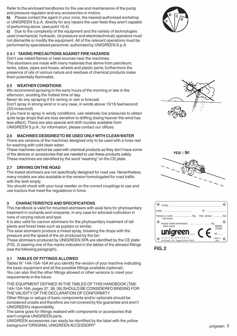
4.5 CARDAN SHAFT
In some models this is supplied on request.The cardan shaft must bear the CE mark.It must always have its own instructions that must be followed scrupulouslyand it should come with a cover bearing the mark, integrated in every part.You should have previously checked the length to avoid:= if it is too long, DANGEROUS THRUST ON THE PUMP SHAFT= if too short, the POSSIBILITY OF DANGEROUS BREAKAGES
THE MINIMUM OVERLAP OFTHE TWO TELESCOPICTUBES MUST NEVER BELESS THAN 1/3 OF THELENGTH OF THE TUBES.
The power that can be transmitted by the cardan shaft must be at least equalto that required to run the atomiser.These power ratings are indicated in tables N° 14A-15A-16A (pages 37-38-39).a) Hook any safety chains to solid anchor pointsb) Check that the button or ringnut “E” (FIG. 6) is correctly engaged andblocked both on the pump side and on the tractor side.c) Don’t exceed an inclination of 30° in any direction for any reasond) With the machine stopped, periodically grease the spiders and the pipes,keeping the connecting zone particularly clean.e) Avoid letting the end of the cardan shaft come into contact with theground with the machine stopped; use the relevant support on some versionsfor this, if your machine has no support, hook the external safety chain to apart of the frame of the machine (ex. control unit support).
NEVER USE THE CARDAN TRANSMISSION IF THE FOLLOWINGPROTECTIVE COVERS ARE MISSING:- TRACTOR POWER-TAKEOFF PROTECTIVE COVER- CARDAN SHAFT PROTECTIVE COVER- FIXED PROTECTIVE COVER ON THE PUMP SHAFT
4.6 PUMP
When using the pump scrupulously observe the instructions in the enclosedhandbook supplied by the manufacturer.The pump can be identified by the ratings plate on the same; the main data onthe pressure and delivery are easy to find on this plate.Normally the pumps mustn’t exceed 550 RPM; a higher speed won’t improveperformance but there is a risk of compromising the life and safety of thepump.There is a safety valve on the pump, calibrated to prevent overpressure. Don’ttamper with this valve for any reason and don’t block or obstruct the pipesconnected to it in any way.
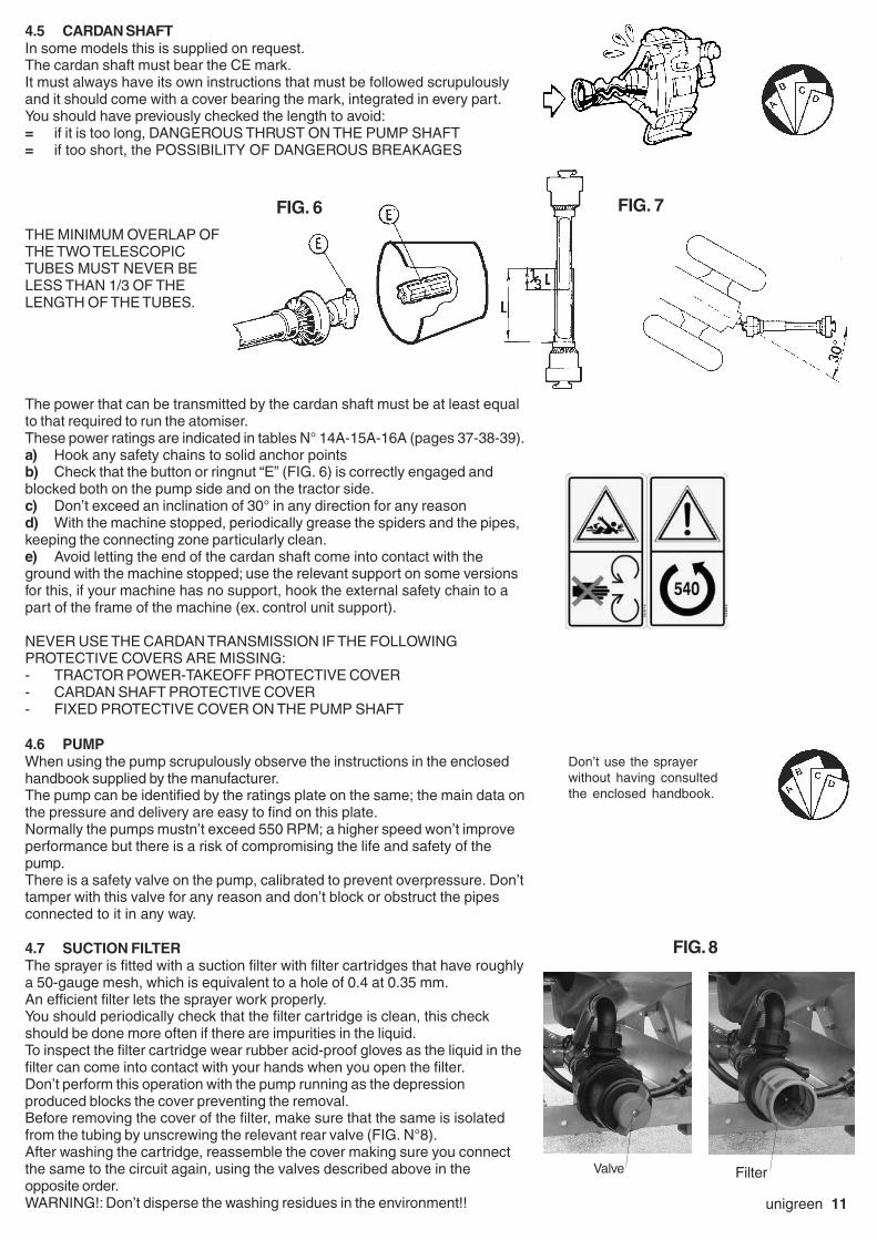
4.7 SUCTION FILTER
The sprayer is fitted with a suction filter with filter cartridges that have roughlya 50-gauge mesh, which is equivalent to a hole of 0.4 at 0.35 mm.An efficient filter lets the sprayer work properly.You should periodically check that the filter cartridge is clean, this checkshould be done more often if there are impurities in the liquid.To inspect the filter cartridge wear rubber acid-proof gloves as the liquid in thefilter can come into contact with your hands when you open the filter.Don’t perform this operation with the pump running as the depressionproduced blocks the cover preventing the removal.Before removing the cover of the filter, make sure that the same is isolatedfrom the tubing by unscrewing the relevant rear valve (FIG. N°8).After washing the cartridge, reassemble the cover making sure you connectthe same to the circuit again, using the valves described above in theopposite order.WARNING!: Don’t disperse the washing residues in the environment!!
FIG. 8
Valve Filter
Don’t use the sprayerwithout having consultedthe enclosed handbook.
FIG. 7FIG. 6

12 unigreen
4.8 PRESSURE REGULATOR
To use the pressure regulator, follow the instructions in the enclosed handbookscrupulously. The pressure regulator controls all of the most important sprayingfunctions, the thorough knowledge of its functions makes work easier and moreprecise.The working pressure and the maximum pressure of the sprayer are determinedby the pressure regulator which also protects the circuit from overpressure inany work conditions. (In serious but very rare cases, if the connecting pipes getblocked the pressure relief valve lets the pressure off)In some setups there may be a pump that can reach a pressure of 725 psi(50 bar) controlled by a regulator designed for 290 psi (20 bar). In this case themaximum pressure that can be reached is 290 psi (20 bar).The regulators can be manual, mounted on the sprayer or at a distance to makethe controls easier to use; or electrical with a control panel in the cabin.There are also regulator versions with mechanical remote controls with a cable.If the tractor has a waterproof cabin the use of electrical controls is obligatory.
4.8.1 COMPONENTS OF THE PRESSURE REGULATOR
Below you will find the indications for the main models fitted on Unigreenproducts.
A main ON-OFF command: “open” lets the fluid flow into the circuit in use;“closed” empties the tank.B maximum pressure valve: adjusted by hand with the relevant knob (drainsthe excess liquid when the set pressure is reached).C jets section tap: opens the corresponding jet boom or drains to thecompensation regulator (G).D auxiliary tap: can be used for various accessories (it is always manual).E volumetric pressure valve (proportional):(when present) it regulates the spraying pressure. The valve automaticallycompensates variations in speed (within the scope of the same gear ratio),keeping the quantity of liquid supplied per surface unit (litres/hectare)unchanged.F self-cleaning filter: filters the delivery liquid.G compensation regulators: suitably regulated, these make it possible tokeep the pressure constant when one or more sections of jets is closed, theydon’t influence treatments with the boom fully open.H manometer: indicates the working pressure.
Connections:R1 supply unionR2 drain unionR3 volumetric drain unionR4 jets section delivery unionR5 auxiliary delivery union
Control box for GCP ELETTRICO electrical regulators
I1 main control valve switchI2 volumetric pressure valve switch (proportional)I3 jets section valves switches
4.8.2 GENERAL INSTRUCTIONS
When using the pressure regulator, scrupulously observe the instructions in theenclosed handbook, below you will find generic indications for the major modelsfitted by Unigreen.All the regulation and adjustment tests must be carried out with clean
water.
Pressure regulators without a volumetric valve (GCP3-way - GRH-RVA)Adjusting the maximum pressure valve= put main control A in the drain position (“OFF”).= loosen the hand wheel of maximum pressure valve B completely(anticlockwise).= start the pump by activating the power-takeoff of the tractor at 540rpm= open main control A (position “ON”), the manometer will be activated= open all of the section valves C (position “ON”)= adjust maximum pressure valve B to the working value (in any case lessthan the safe maximum pressure the system can reach).
Don’t use the sprayerwithout having consultedthe enclosed handbook.
way

unigreen 13
Pressure regulators with a volumetric valve (GCP ELETTRICO)
Adjusting the maximum pressure valve= put main control A in the drain position (“OFF”).= loosen the hand wheel of maximum pressure valve B completely(anticlockwise).= open volumetric valve E completely.= start the pump by activating the power-takeoff of the tractor at 540rpm= open main control A (position “ON”), the manometer will be activated= open the drain tap on filter F slightly (only GCP ELETTRICO).= close volumetric valve E completely. If the pressure rises over themaximum limit of the system, make sure maximum pressure valve B is open(see previous indications)= open all of the section valves C (position “ON”)= adjust maximum pressure valve B to a value over that of the workingpressure (generally 145-203 psi / 10-14 bar) and in any case lower than thesafe maximum pressure that the system can reach.
Adjusting the volumetric pressure.= with the volumetric pressure valve E adjust the pressure to the value thetreatment will be done at (the pressure is indicated on the nozzles tables onthe basis of the tractor speed and litres/hectare to spray)Warning! The working pressure must be adjusted with the volumetric
valve and not with the maximum pressure valve. In the case the
working pressure is too near to the calibrated pressure of the
maximum pressure valve, the proportional valve may not be able to
compensate the speed variations correctly.
Adjusting the compensated returns= close only one tap of section C (position “OFF”).= adjust the corresponding compensator G until you return to the pressureset previously (displayed on the manometer).= open and close the tap of section C and check that the pressure remainsconstant.= repeat the above operations for all the section taps.If the types of nozzles aren’t changed the regulations carried out will guaranteea constant spraying of the liquid also per treatments that are done at differentworking pressures.NB: if the type of nozzle is changed then the calibrating will have to be doneagain.
4.9 DELIVERY FILTERS (ONLY EQUIPPED MODELS)
This is particularly useful when using small nozzles (low volume), they arenormally mounted on the jet booms and have a filter cartridge with a 40-gaugemesh (the equivalent of a 0.4 mm hole).In the RV version, the standard cartridge has a 86-gauge mesh (the equivalentof a 0.25mm hole) and another manometer is mounted after the cartridge tomake fault-finding easier.At the end of each treatment cycle you should clean the cartridge: turn thejets to the closed position, put the command under pressure and open the tapunder the filter to drain the tank for a few minutes.You should clean the cartridge by hand periodically, on the basis of theproduct used. Stop the pump to clean. Wear rubber gloves and the otherpersonal protective equipment when cleaning.
FIG. 9
40 mesh RV 86 mesh
14 unigreen
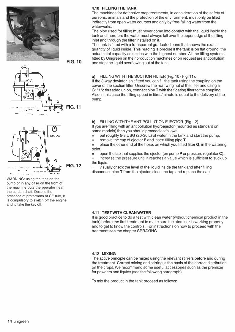
4.10 FILLING THE TANK
The machines for defensive crop treatments, in consideration of the safety ofpersons, animals and the protection of the environment, must only be filledindirectly from open water courses and only by free-falling water from thewaterworks.The pipe used for filling must never come into contact with the liquid inside thetank and therefore the water must always fall over the upper edge of the fillinginlet and through the filter installed on it.The tank is fitted with a transparent graduated band that shows the exactquantity of liquid inside. This reading is precise if the tank is on flat ground; theactual total capacity coincides with the highest number. All the filling systemsfitted by Unigreen on their production machines or on request are antipollutionand stop the liquid overflowing out of the tank.
a) FILLING WITH THE SUCTION FILTER (Fig. 10 - Fig. 11).If the 3-way deviator isn’t fitted you can fill the tank using the coupling on thecover of the suction filter. Unscrew the rear wing nut of the filter and using aG1"1/2 threaded union, connect pipe T with the floating filter to the coupling.Also in this case the filling speed in litres/minute is equal to the delivery of thepump.
b) FILLING WITH THE ANTIPOLLUTION EJECTOR (Fig. 12)If you are filling with an antipollution hydroejector (mounted as standard onsome models) then you should proceed as follows:= put roughly 5-8 USG (20-30 L) of water in the tank and start the pump.= remove the cap of ejector E and insert filling pipe T.= place the other end of the hose, on which you fitted filter G, in the wateringpoint.= open the tap that supplies the ejector (on pump P or pressure regulator C).= increase the pressure until it reaches a value which is sufficient to suck upthe liquid.= visually check the level of the liquid inside the tank and after fillingdisconnect pipe T from the ejector, close the tap and replace the cap.
4.11 TEST WITH CLEAN WATER
It is good practice to do a test with clean water (without chemical product in thetank) before the first treatment to make sure the atomiser is working properlyand to get to know the controls. For instructions on how to proceed with thetreatment see the chapter SPRAYING.
4.12 MIXING
The active principle can be mixed using the relevant stirrers before and duringthe treatment. Correct mixing and stirring is the basis of the correct distributionon the crops. We recommend some useful accessories such as the premixerfor powders and liquids (see the following paragraph).
To mix the product in the tank proceed as follows:
FIG. 12
FIG. 11
WARNING: using the taps on thepump or in any case on the front ofthe machine puts the operator nearthe cardan shaft. Despite thepresence of protections at CE rule, itis compulsory to switch off the engineand to take the key off.
FIG. 10

unigreen 15
FIG. 13 FIG. 14
FIG. 15
a) high-pressure machines from 435 to 870 psi (from 30 to 60 bar) (FIG. N°13): run the stirrer (or ejector) for roughly 10-15 minutes at the maximumpressure available
b) low pressure machines, max 290 psi (20 bar)= with a drilled pipe on the drain, run the pump at roughly 540 RPM with thepressure regulator on drain for at least 10-15 minutes. (FIG. N° 14)= with the stirrer on a delivery, run the pump supplying the stirrer (or ejector)at the maximum pressure available for at least 10-15 minutes. (FIG. N° 13)
Some models with very small tanks aren’t equipped with mixers, you shoulduse the drain of the pressure regulator: run the pump at roughly 540 RPM withthe pressure regulator in the drain position for at least 10-15 minutes. (FIG. N°15)
4.12.1MANUAL PREMIXING
Dilute the active principle by hand before introducing it into the tank, (youmust wear suitable protective clothing such as rubber gloves, a mask orgoggles, overalls, etc.).
4.12.2PREMIXER ON COVER (OPTIONAL):
Open the cover and pour all of the chemical powder into the filter, close thecover and open the supply tap until all of the powder has dissolved.
4.13 WASHING THE ATOMISER
After every treatment, thoroughly clean the equipment, washing it with waterinside and out. Dirty equipment is very dangerous for people and in particularfor children.Discharging the residues of washing in the environment without takingprecautions is forbidden as this pollutes water courses. Distribute the residueson the field or the crops where they won’t cause any damage.
4.13.1CIRCUIT WASHER AND TANK WASHER
Some machine models are fitted with a circuit washer tank (FIG.16). This tankmust be filled with clean water and used to rinse the entire circuit including thesuction, delivery, pump, pressure regulator, jets and nozzles. Thanks to thepractical rotary nozzle it also rinses the inside surfaces of the tank.
NB: To completely clean the tank and the pipes of any residues of the variousactive principles, we recommend adding 4,5 lb (2kg) of soda to the washingliquid for every 26 USG (100 L) of water.
At the end of the treatment, wash the circuit and the tank.
a) Stop the diaphragm pump disengaging the power-takeoff.b) Check you have filled the circuit washer tank (C).c) Make sure the main control of the pressure regulator is OFF and that allthe boom sectors are closed.d) Turn suction deviator A to the circuit washer position (H2O).e) Start the diaphragm pump by engaging the power-takeoff.f) Increase the engine speed until all of the liquid in circuit washer tank Chas been sucked up.g) Turn the diaphragm pump off and turn deviator A to the work position(TANK).h) Turn the main control to ON, so there is pressure in the circuit.i) Start the diaphragm pump again and use the tank washing tap on theregulator (or on pump P) that supplies jet B.j) After a few minutes you can close the tank washing tapk) Distribute the washing residues over a portion of the field where it won’tcause damage.l) After you have finished washing, stop the diaphragm pump.
NB: at the end of the washing cycle, if there is the risk of frost, pour roughly1 lb (500 grams) of normal antifreeze for auto vehicles into the tank.
A
BC
F
P
This symbol identifiesthe clean water tankon the machine usedto wash the circuit
WARNING: using the taps on the pump or in anycase on the front of the machine puts theoperator near the cardan shaft. Despite thepresence of protections at CE rule, it iscompulsory to switch off the engine and to takethe key off.
FIG. 16

16 unigreen
5 BLOWER GROUP
All the atomisers have a high speed fan rotor. You must take great care
and beware of the effects that this can provoke: such as the aspiration and
projection of foreign bodies which, although of a small size, can be very
dangerous especially for the eyes and face.
5.1 AXIAL BLOWER GROUP WITH PULLEY
The atomisers that have a drive transmission between the pump and fan withpulleys are equipped with a neutral gear; the multiplied ratio is 1:4.26, therotation speed of the fan is 2,300 RPM.
You should periodically check the tension of the belts; if they become too slackyou should tension them again.
To do this for the models equipped with a specific system belt tensioning sys-tem, use the screw indicated to the side ( FIG. 17).For all the other models use an adjustable wrench on the nut indicated in thefigure to the side to move the base and tension the belts (FIG. 18)
5.2 AXIAL BLOWER GROUP WITH MULTIPLIER
The transmission of the drive from the pump to the fan is done through amultiplier with one or two neutral gears.Normally the rotation speed of the fan is 1950 RPM in first gear and 2500 RPMin second in the multiplier with 2 gear ratios (multiplied ratios 1:3.6 - 1:4.6) and2,500 RPM in the multiplier with one gear ratio (1:4.6)with the power-takeoffrunning at 540 RPM.You can change from one gear to the next with the lever on the multiplier, madeaccessible through the opening on the side in the rear left part of the machine orat a distance on the right side. The lever has 2 or 3 positions depending on thenumber of gears and the central position is neutral (to use only the pumpwithout the fan).
There are two models of blower groups with rear suction:- Axial blower (FIG19A): used for treatments similar to traditional multiplierblower groups, with delivery of the air in a circular crown.
- Tangential blower: for use in small and medium espalier rows of vines. Thereare pulley drive versions or multiplier versions, adjustable jets can be mountedto spray the vegetation at various heights.
WARNING: the gear change lever must only be used with the power-takeoffdisengaged and the fan stopped. If it is difficult to engage, turn the cardan shaftslightly by hand to find the right position of the lever (make sure the tractor isturned off).
There are two deflectors (one on the right and one on the left) in the bottom partof the delivery outlet of the fan groups which define the direction of the airflow;lower if the deflector is lowered and higher if the deflector is raised. For thesystem to work properly it should be set up as follows: the left deflector(looking at the atomiser from behind) raised and the right one lowered inmachines with a multiplier, vice versa in those with a pulley (as the fan turns inthe opposite direction).
For the maintenance of the multiplier (see point 8.2.3 Multiplier Lubrication).
FIG. 19B
FIG. 17
FIG. 18
Speed changelever
Belt tensioningsystem
Belt tensioningsystem
FIG. 19A

unigreen 17
WORK TEMPERATUREHeat is generated by the friction between the various moving components and onthe basis of the power transmitted. The temperatureof the multiplier or disengaging box depends on the capacity to dissipate heat to thesurrounding environment and therefore the surfaces involved in the heat exchangeand the environmental conditions.The specifications refer to environmental conditions with a temperature between-10° +50°C (14°C -122°F).
The working temperature limit of the box is 90°C (200°F) established to prevent theageing of the seals and guarantee a sufficient viscosity of the oil. The heat makesthe air in the box expand and therefore increases the pressure inside. The correctuse of the oil seals is guaranteed up to an internal pressure of 7 psi (0.5 bar). Boxesdesigned to be used for particularly heavy duty work are equippedwith a breather cap that can be fittedon any cast iron box on request.
5.3 BLOWER GROUP WITH FRONT SUCTION
These models have front suction with delivery of the air obliquely to the rear ofthe machine. This characteristic guarantees greater penetration into the veg-etation (see fig. 20A-20B)
There are two models of blower groups with front suction:- Axial fan: used for treatments similar to traditional multiplier blower groups,with delivery of the air in a circular crown (fig. 20A-B).- Tangential fan: for use in small and medium espalier rows of vines. Thereare pulley drive versions or multiplier versions, adjustable jets can be mountedto spray the vegetation at various heights.The vanes of these blowers have an inclination that can be adjusted by 5°, withpositions from 20° to 40° (as standard this is set at 35°); to adjust the inclina-tion you have to order the appropriate adjustment discs. This operation mustonly be performed by qualified personnel respecting the position of the singlevanes so as not to vary the dynamic balance of the fan; unbalanced blowerscan cause rapid wear of the multiplier and the fan rotor itself making the ma-chine unsafe.
5.3.1 SINGLE-SIDE BLOWER GROUP
The sprayer can be equipped with a single-side blower group like the oneshown in figure 21. The operating principle is similar to that of the blower groupwith front suction, the only difference being that the treatment is only on oneside.
5.4 AXIAL ROTOR
Generally the new models of rotors are fitted with 7 vanes made of aluminiumor nylon + fibreglass and the vanes have a variable inclination from 20° to 40°with step adjustment by 5° (in some cases there are drilled reference discs)FIG. 22.The angular movement of all of the vanes, if done correctly, doesn’t changethe dynamic balance of the blower group.To change the inclination of the vanes (as standard this is set at 35°) proceedas follows:a) Remove the protective grill.b) Unscrew screws A that hold the spinner (central cover), each vane hastwo blocking screws B at the side, one on the right and one on the left.Unscrew the two screws enough to turn the vane the degrees necessary(replace the drilled discs when fitted). To make the adjustment easier, thereare reference notches on blocking element C.c) After you have positioned the vane, perform the same operation on thenext one and screw the screws of the first in enough to block it in place.d) Repeat the operation on all the vanes and after you’ve checked that allhave the same angle, reassemble the spinner and the protective grill.The fan is balanced dynamically; the different numbers of washers under thescrews blocking the vanes are for balancing.You shouldn’t change the position of the washers or add or remove any. Onlytighten down the screws with moderate force as they have an aluminiumthread. FIG. 22
FIG. 20A
FIG. 21
FIG. 20B
drilled reference disc(only fitted models)

18 unigreen
5.5 CLUTCH
Big aluminium and nylon blowers have a centrifugal type clutch that makes itpossible to engage the fan rotor gradually.This prevents jerky starts, due to the inertia of the fan rotor, which can have anegative effect on the transmission.For the centrifugal clutch to work properly the speed of the power-takeoffmustn’t be less than 450 rpm, especially if you are using the first gear of themultiplier.Generally clutches with shoes/plates made of sintered material with a highcoefficient of friction are fitted, on some low power models rubber clutches maybe fitted.
5.6 OPTIONAL DEFLECTORS AND ACCESSORIES
The atomisers are fitted with deflectors underneath for the optimal regulation ofthe airflow towards the zone to be treated. To adjust these, simply pull or pushthe deflector, positioning it in the desired way (FIG.23).
Top deflectors can also be supplied on request to improve the regulation of theairflow towards the lateral zones without dispersing the product upwards. To ad-just these, simply loosen the black lever (shown in figure 24), position the de-flectors and lock the lever again.
5.7 CANNON BLOWER GROUP
The cannon blower group is equipped with a multiplier similar to the normal axialblower groups and all of its operating characteristics are the same.The main difference with respect to the axial blower groups is that thecentrifugal fan rotor is made of galvanised steel, the fan rotors in this type arefixed and can’t be adjusted, for the clutch see the previous paragraph. This fanrotor can usually produce a delivery which is much higher with a very highspeed airflow (Fig. 25).
The cannon fan is mounted on a thrust block that can be adjusted by hand byunscrewing the relevant locking screw. This adjustment must be done with thefan rotor stopped because the high speed of the air make the movement of thefan dangerous.
5.7.1 MANUALLY INCLINABILE HEAD
The cannon blower group can be equipped with a pivoting head (max inclination180°) adjustable by hand.
5.7.2 HYDRAULIC DRIVEN HEADS
On request hydraulic pivoting (inclination 90° roughly) and rotating (max rotation270°) heads are available.
5.7.3 HYDRAULIC DRIVES
The cannon fans can be equipped with hydraulic drives: with the cylinder fitteddirectly (30° inclination roughly) or a motor with a pinion and chain (180°inclination roughly).
5.7.4 OIL FEED FROM TRACTOR
(for hydraulic systems)Connect the delivery and discharge quick-fit coupling to the respectiveconnections, respecting the direction of flow.The distributor inlet pipe is connected to the aluminium flow separator valvenext to the distributor.The flow separator must be adjusted correctly so it sends less than1-1,3 USG/min (4-5 L/1°) to the distributor.To prevent the cylinders moving at a dangerous speed, adjust the relevantchokes near the cylinders. If the registration ringnuts aren’t visible then fixedchokes are fitted. The chokes are fitted on the discharge line of the movementto slow.Any impurities in the oil could block the chokes and as a consequence blockthe cylinder; remove the dirt if necessary. The maximum pressure valves of thedistributors are regulated to a pressure of around 2175 psi (150 bar).
FIG. 23
FIG. 24
FIG. 25
unigreen 19
To prevent the excessive heating of the oil we recommend supplying thedistributor of the sprayer only when the cylinders are being used.We recommend having qualified personnel do any adjustments.Pay attention to the integrity and efficiency of the hydraulic components andin particular to the pipes to prevent the risk of bursting.Do a full check on the pipes and components at least once a year, werecommend replacing hydraulic pipes every 3-4 years.
6 SPRAYING
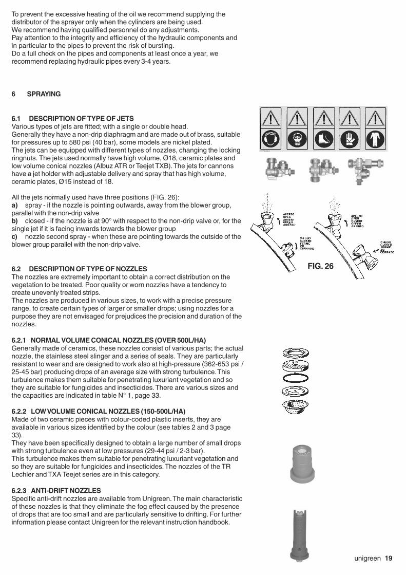
6.1 DESCRIPTION OF TYPE OF JETS
Various types of jets are fitted; with a single or double head.Generally they have a non-drip diaphragm and are made out of brass, suitablefor pressures up to 580 psi (40 bar), some models are nickel plated.The jets can be equipped with different types of nozzles, changing the lockingringnuts. The jets used normally have high volume, Ø18, ceramic plates andlow volume conical nozzles (Albuz ATR or Teejet TXB). The jets for cannonshave a jet holder with adjustable delivery and spray that has high volume,ceramic plates, Ø15 instead of 18.
All the jets normally used have three positions (FIG. 26):a) spray - if the nozzle is pointing outwards, away from the blower group,parallel with the non-drip valveb) closed - if the nozzle is at 90° with respect to the non-drip valve or, for thesingle jet if it is facing inwards towards the blower groupc) nozzle second spray - when these are pointing towards the outside of theblower group parallel with the non-drip valve.
6.2 DESCRIPTION OF TYPE OF NOZZLES
The nozzles are extremely important to obtain a correct distribution on thevegetation to be treated. Poor quality or worn nozzles have a tendency tocreate unevenly treated strips.The nozzles are produced in various sizes, to work with a precise pressurerange, to create certain types of larger or smaller drops; using nozzles for apurpose they are not envisaged for prejudices the precision and duration of thenozzles.
6.2.1 NORMAL VOLUME CONICAL NOZZLES (OVER 500L/HA)
Generally made of ceramics, these nozzles consist of various parts; the actualnozzle, the stainless steel slinger and a series of seals. They are particularlyresistant to wear and are designed to work also at high-pressure (362-653 psi /25-45 bar) producing drops of an average size with strong turbulence. Thisturbulence makes them suitable for penetrating luxuriant vegetation and sothey are suitable for fungicides and insecticides. There are various sizes andthe capacities are indicated in table N° 1, page 33.
6.2.2 LOW VOLUME CONICAL NOZZLES (150-500L/HA)
Made of two ceramic pieces with colour-coded plastic inserts, they areavailable in various sizes identified by the colour (see tables 2 and 3 page33).They have been specifically designed to obtain a large number of small dropswith strong turbulence even at low pressures (29-44 psi / 2-3 bar).This turbulence makes them suitable for penetrating luxuriant vegetation andso they are suitable for fungicides and insecticides. The nozzles of the TRLechler and TXA Teejet series are in this category.
6.2.3 ANTI-DRIFT NOZZLES
Specific anti-drift nozzles are available from Unigreen. The main characteristicof these nozzles is that they eliminate the fog effect caused by the presenceof drops that are too small and are particularly sensitive to drifting. For furtherinformation please contact Unigreen for the relevant instruction handbook.
FIG. 26

20 unigreen
6.3 CALIBRATING AXIAL FAN ATOMISERS
(Tables on pages 25 - 30)The tables on pages 25-30 let you easily calculate the distribution in litres/hectare of the atomisers with the standard fittings, proceeding as indicatedbelow:a) Choose the table relevant to the blower group of the atomiser in question (themain reference is the number of jets)b) Find the distance between the rows of the vegetation and the diameter of thenozzles used (ceramic plates, TR or TXA).c) In the horizontal strip, choose the working speed and the distribution in litres/hectare and on the vertical scale find the pressure to use.d) Adjust the pressure to obtain the treatment required.If the distance between the rows is different from that in the table you caneasily calculate the distribution in proportion: for example with a distancebetween the rows of 26' (8 m), divide the figure for the litres/hectare of thedistance between the 13' (4 m) rows by half, with a distance between the rowsof 8' (2.5 m) double the figure for the distance between the 16' (5 m) rows.The last line of the table indicates the overall delivery of the fan.If the atomiser is fitted with non-standard nozzles, the spraying tables of thesingle nozzles per atomiser are on page 34.To calculate the distribution in litres/hectare, use the following formula:
Vd = 600 x Q
I x V where: Vd = volume to distribute (L/ha)Q = sum of the nozzles delivery (L/min)I = distance between the rows (m)V = tractor speed (Km/h)
EXAMPLE:Distance between the rows: 5 m
Speed: 6 Km. / h
Working air pressure 30 barFan Ø 800 with 14 standard, high volume nozzles (Ø 1.0)
Q total delivery of the nozzles (Tab. 1 page 34) 2.96x14= 41.44 L/min
Vd = 600 x 41.44 = 829 L/ha 5 x 6
N.B. : Depending on the season the vegetation may be more or less luxuriant;bear this in mind before starting the treatment. If the plants don’t have muchfoliage you should diminish the quantity of litres per hectare using lowerpressures or closing one or more jets of the fan.
6.4 CALIBRATING CANNON ATOMISERS
( Tables on pages 31-33 )Atomisers with a cannon blower group are mainly intended for treating foresttrees or other tall plants that it is impossible to drive into with the sprayer (forexample tobacco or similar cultivations). They are also frequently used in culti-vation under mobile greenhouses.When shooting the atomised chemical mix at distances, that can even be over130 feet (40 m), it isn’t possible to verify with the exact distribution on the areatreated. Due to the effect of the wind, the presence of turbulence and the obsta-cle of the same plants being treated, we don’t recommend using cannons withchemical products that need to be distributed with great precision.Don’t use herbicides or similar products.
6.4.1 TREATMENTS ON TALL PLANTS
a) Use the tables of pages 31-33 choosing the one relevant to the type ofcannon to use and the number of jets.b) On the last line choose the delivery in USG/minute that goes with thechosen working pressure.c) Then spray the US Gallons desired on the plant defining the necessarytreatment time.When treating a poplar grove or in similar situation there are photocells for theautomatic management of the opening of the jet in the presence of the plant totreat, available on request.
N.B. to calculate the different ranges it issufficient to multiply the value lt/hectare by thecorresponding width indicated in the table anddivide it by the new width.
Example-In the table:23 USG/acre with row distance m = 13 feet.
23x13 = 20 USG/acre with row distance 15 feet 15

unigreen 21
6.4.2 TREATMENTS ON HERBACEOUS CULTIVATIONS
a) Use the tables of pages 31-33 choosing the one relevant to the type ofcannon to use and the number of jets.b) Find the range and the diameter of the nozzles used (ceramic plate or TRnozzles).c) In the horizontal strip, choose the working speed and the distribution inlitres/hectare and on the vertical scale find the pressure to use.d) Adjust the pressure to obtain the treatment required.Note: the minimum range indicated in the table can vary significantly
according to the adjustment of the single jets (screwed in more or less).
To verify the exact delivery of the fan do tests with clean water.
7 HAND LANCES
When using hand lances bear in mind the following notes:= Don’t direct the jet of liquid towards electric power lines or zones wherethere is electrical current, houses or where people might pass.= Don’t point the jet at people or animals.The jet can cause serious injuries simply due to the mechanical force of theliquid under pressure.= Never block the spraying lever of the lance in an open position because ifthe lance falls it will be uncontrollable.= At the end of work after you have stopped the pump, make sure that anyresidual pressure in the pipes under pressure has been drained to avoidunexpected jets when putting the lance away.There are various types of lances; with a lever, mitra spray gun and pistol grip.For further information please refer to the handbook in the package.The lever lance is controlled by opening lever A which, depending on howmuch it’s pressed, produces a conical spray or direct jet. The standard nozzleis Ø 1.5The mitra spray gun can produce a direct jet or a conical spray and the typeof spray is selected by pushing lever B forwards or backwards. Use lever C toopen the jet. The standard nozzle is Ø 2.5Replacement nozzles are available for all of the lances and the capacities areindicated in the tables TAB.4 and TAB.5 ( page 34).
CB
A

22 unigreen
8 MAINTENANCEAll of the maintenance operations and repairs must be carried out with the ma-chine and cardan shaft stopped and the tank and circuit clean of any residuesof chemical products.The maintenance of the atomiser is essential for maintaining a high level ofsafety. Also consult the single handbooks of the main components of the atom-iser.
8.1 PROGRAMMED MAINTENANCE(TAB. N° 7, page 36)
We recommend using a table of programmed maintenance to follow in time tokeep the atomiser in an efficient working condition.For major and important maintenance jobs we recommend using the normalUNIGREEN assistance service available from your reseller, (if necessary)replacing parts using original spare parts only.
8.2 ROUTINE MAINTENANCE= After every treatment wash the inside of the tank and the entire circuit asindicated in paragraph 4.13= Periodically check that the suction and delivery filters are clean= Check the oil level in the volumetric compensator of the pump= The use of chemical products that are particularly damaging for a nitrilerubber mix can cause the diaphragm to break before time.In these conditions check the state of the components more often. There arediaphragms made of special materials (viton and desmopan) that are availableon request.= When doing treatments with copper hydroxide you should take great careto thoroughly clean the system, washing it after each treatment becausehydroxides attack parts that aren’t painted or protected by hot galvanising.To prevent chemical attacks we recommend spraying transparent paint on theparts that are most exposed to the product and equipping the atomiser withstainless steel pressure gauges.
8.2.1 CLEANING THE NOZZLESCheck the state of wear of the nozzles and replace them when the delivery isover 30-35% of the theoretical level.If you notice even a partial blockage of a nozzle proceed as follows:- drain the pressure and stop the machine- dismantle the screw or bayonet ringnuts holding the nozzles- clean with a small brush or compressed air, don’t use nails, punches orbradawls- reassemble the nozzles and the ringnuts, replacing the filters and seals.
8.2.2 LUBRICATIONThe moving mechanical components must be lubricated to prevent wear andoverheating. This lubrication can be done with grease or oil: oil allowssignificantly higher speeds, in general grease is used to lubricate bearings witha vertical or inclined axis as it stays in the zone for longer.
8.2.3 MULTIPLIER LUBRICATIONThe multiplier and disengaging boxes are normally lubricated in an “oil bath”, inspecial cases NLGI n.0 grease is used. The viscosity is an essentialcharacteristic of a lubricant oil and this is indicated by the SAE (SOCIETY OFAUTO-MOTIVE ENGINEERS) classification of the oils for gearboxes anddifferentials. Special additives improve the capacity of the oil to maintain alubricant film also at high pressures and temperatures. We recommended usingSAE 90 oil for the multiplier and disengaging boxes. The quantity of oil isestablished by the level cap. A greater quantity of oil doesn’t improve theconditions of lubrication and can cause overheating in the box. Changing the oilprotects the parts from the dangers associated with wear and the presence ofmetallic particles that can be present, especially in the first period of use. Werecommend replacing the oil after the first 50 working hours and thensubsequently every 500 hours.The quantity of oil needed is indicated on the sticker near the multiplier (FIG.23)WARNING: the oil used mustn’t be dispersed in the environment and mustbe collected the relevant containers.
8.3 EXTRAORDINARY MAINTENANCEAt the end of a season of intense use, or every two years of normal use, it is agood idea to have a specialised service technician perform a general check onthe machine.
FIG. 29

unigreen 23
8.4 REPAIRSWe recommend having the normal UNIGREEN assistance service available from our resellerperform any repairs or contact a specialised workshop. During all of the repairs, in particularwhen welding, the machine and the circuit must be clean of any residues of chemical product.If the machine has to be lifted (for example to change a wheel) follow the instructions in point4.3 of the present handbook.Also make sure the machine is stopped, connected to the tractor, and use the relevant chocksto block the wheel still on the ground.If you use a jack (manual or hydraulic) make sure you use a jack that is suitable for the frameso it can’t slip and put it in the right position. The jack must be placed under the main frame ofthe machine near the wheel to change. Make sure the ground is compact: if necessary usewooden beams or other sufficiently resistant material to broaden the supporting base of thejack.
8.5 STORAGE IN A WAREHOUSE AND TRANSPORTATIONThe sprayer must be kept in a closed place away from excessive humidity and protected fromfrost. Especially if electrical pressure regulators, electrical motors, a spraying computer orsimilar components are fitted.Before storing the machine, after you have washed it, apply a light coat of oil.If the temperature might drop to below zero, drain any residual liquid or add roughly 0,2 USG(0,5 L) of normal antifreeze for auto vehicles.To transport the machine follow the instructions in point 4.3 of the present handbook.
8.6 PUTTING BACK INTO SERVICE AFTER WINTER LAYUPBefore using the machine again after a long period of inactivity you should perform somegeneral checks, following the instructions in point 4.2 and drain any antifreeze.Never start the shaft of the pump if you think there may by ice inside. To check this,make sure you can turn the shaft by hand without connecting it to the tractor.After you have connected the machine to the tractor (see point 4.4) following the instructionsin the present user’s handbook and in the enclosures of the pump, pressure regulator andaccessories.
8.7 DEMOLITION AND DISPOSALWhen the sprayer will be put out of service you should wash it with great care to remove anyresidues of chemical product, follow the instructions in point 4.13 of the present handbook.ATTENTION: It is necessary to adopt appropriate Individual Protection Devices in manipulatingwaste.The disposal of waste deriving from the demolition of the machine must be carried outrespecting the environment, avoiding soil, air and water pollution.Local legislation in force in the matter must be respected in any case.Remember that waste is understood as any substance or object that enters into the categoriesshown in attachment A in part IV of Legislative Decree 152/2006, that the holder hasdestroyed, has decided or is obliged to destroy.Waste deriving from the demolition of the machine is classifiable as special waste.
8.7.1 MATERIALS FOR DEMOLITIONNon-dangerous special waste is that which can be recovered, according to the February 1998Ministerial Decree:· Iron, aluminium, stainless steel and copper materials· Plastic materials· Electronic cards· Hydraulic oil· Electrical plant
8.7.2 INDICATIONS FOR A SUITABLE TREATMENT OF WASTEThe Correct management of special waste envisages:- stocking in suitable places, avoiding mixing dangerous waste with the non-dangerous.- ensuring that authorised carriers and receivers carry out its transport and disposal/recovery.Transport of one's waste to authorised collection centres is allowed exclusively if you areenrolled in the Environmental Management Register.
8.7.3 ELECTRICAL AND ELECTRONIC APPARATUS WASTE (EEAW)The Italian government has adopted the European Parliament directives in the matter of thedisposal of electrical and electronic waste (EEAW) (2002/95/CE and 2003/108/CE Directives)with Legislative Decree n° 151,July 25 2005).The measures: in particular, the decree established measures and procedures aimed at:a) forestalling the production of EEAW;b) promoting the re-use, recycling and other forms of EEAW recovery, in order to reduce thequantity to send for disposal;c) improving, in terms of the environment, the actions of the subjects who participate in thelife-cycle of these apparatuses (producers, distributors, consumers and operators directlyinvolved in the treatment of EEAW);d) reducing the use of dangerous substances in electrical and electronic apparatus.

24 unigreen
Commonly used spare parts
part description code
single Ø18 non-drip jet for atomiser withdiaphragm (1/4" mount) without nozzles 1224/0194F
double Ø18 non-drip jet for atomiser withdiaphragm (1/4" mount) without nozzles 1224/0195F
double 15 + Ø18 non-drip jet Ø for cannon withdiaphragm (1/4" mount) without nozzles 1224/0199F
ceramic conical nozzle Ø0,8 3400/0394Fhigh volume Ø1,0 3400/0395Ffor Ø18 atomiser jet Ø1,2 3400/0396F
Ø1,5 3400/0397FØ1,8 3400/0398FØ2,0 3400/0399F
diffuser Ø18 mm. closed B1606.0011for atomiser jet Ø1,0 B1606.0012
Ø1,2 B1606.0013Ø1,5 B1606.0014Ø1,8 B1606.0015
filter for Ø18 jet holes Ø 0,8 1002/0110F
Ceramic, conical nozzle kit, Nozzle Ø0,8 Dif. Ø1,0 Filter Ø0,8 3400/0400Ffilter diffuser and seal Nozzle Ø1,0 Dif. Ø1,0 Filter Ø0,8 3400/0401F
for Ø18 mm jet Nozzle Ø1,2 Dif. Ø1,2 Filter Ø1,0 3400/0402FNozzle Ø1,5 Dif. Ø1,5 Filter Ø1,0 3400/0403FNozzle Ø1,8 Dif. Ø1,8 Filter Ø1,0 3400/0404FNozzle Ø2,0 Dif. Ø1,8 Filter Ø1,0 3400/0405F
Clamp kit for fixing G1/4" jets on Ø1/2" booms 1805/0034F
Clamp kit for fixing G1/4" jets on Ø1/2" booms+ M8 F thread 1805/0050F
TXA80-005 Lilac 3400/0611FISO nozzle TXA80-067 Olive 3400/0612F
ceramic conical TXA80-01 Orange 3400/0613Fwith slinger TXA80-015 Green 3400/0614F
+ OR TXA80-02 Yellow 3400/0615FTXA80-03 Blue 3400/0616FTXA80-04 Red 3400/0617FTXA80 -05 Brown /
The decree imposes the limitation and elimination of several substances present in EEAW: lead,mercury, cadmium, chrome, hexavalent chrome, polybrominated biphenyl, polybrominated diphenyland polybrominated diphenyl ethers.The machine has been designed and created in conformity with this directive. Follow the indicationsshown below.The symbol to the side, showing a barred garbage can on wheels, indicates the separate collectionof the electrical and electronic apparatuses of the machine.
The user of the present machine can contact the collection centres instituted by the LocalAuthorities or the UNIGREEN Company directly, or request withdrawal by the dealer, in order tocarry out correct disposal of the waste.
Teeje
t

unigreen 25
TABLES FOR CALIBRATING ATOMISERS Ø500-600
TABLES FOR CALIBRATING ATOMISERS
N.B. to calculate the different ranges it is sufficient to multiply the value USG/acre by the corresponding widthindicated in the table and divide it by the new width (see chapter 6.3, page 20).
unigreen spa Tabella erogazione in USG/Acres Gr.Ventola Ø500-Ø600 8 getti
USA VERSION USG/Acres spreading rate table for Blower Ø500-Ø600 8 NOZZLES
Ceramic Nozzle Tips Ø1,0 mm Ceramic Nozzle Tips Ø1,2 mm Larghezza di lavoro
PRESSURE psi 145 218 290 363 435 580 725 145 218 290 363 435 580 725 working width
2,2 93 106 121 135 146 167 183 125 153 175 195 215 247 2722,5 81 93 106 118 128 146 160 109 134 153 171 188 216 2383,1 65 74 85 94 102 117 128 87 107 123 137 150 173 190 9,843,7 54 62 71 78 85 97 107 73 89 102 114 125 144 1584,3 46 53 60 67 73 83 91 62 77 88 98 107 123 136 9,8 feet
2,2 69 80 91 101 110 125 137 94 115 131 146 161 185 2042,5 61 70 79 88 96 109 120 82 100 115 128 141 162 1783,1 49 56 64 71 77 87 96 65 80 92 102 113 130 143 13,123,7 41 46 53 59 64 73 80 55 67 77 85 94 108 1194,3 35 40 45 50 55 62 69 47 57 66 73 81 93 102 13 feet
2,2 56 64 73 81 88 100 110 75 92 105 117 129 148 1632,5 49 56 64 71 77 87 96 65 80 92 102 113 130 1433,1 39 45 51 57 61 70 77 52 64 74 82 90 104 114 16,43,7 32 37 42 47 51 58 64 44 54 61 68 75 86 954,3 28 32 36 40 44 50 55 37 46 53 59 64 74 81 16,4 feet
USG/min. 3,96 4,54 5,17 5,76 6,26 7,13 7,81 5,33 6,55 7,5 8,34 9,19 10,6 11,6 Tab. 3215/000F
single nozzle 0,5 0,57 0,65 0,72 0,78 0,89 0,98 0,67 0,82 0,94 1,04 1,15 1,32 1,45 USA VERSION
Mile
s/ho
ursp
eed
US
G/a
cre
US
G/a
cre
US
G/a
cre
Mile
s/ho
ursp
eed
Mile
s/ho
ursp
eed
unigreen spa Tabella erogazione in USG/Acres Gr.Ventola Ø500-Ø600 8 getti
USA VERSION USG/Acres spreading rate table for Blower Ø500-Ø600 8 NOZZLES
TR80-01 ARANCIO TR80-015 VERDE Larghezza di lavoro
PRESSURE psi 73 102 145 174 218 261 290 73 102 145 174 218 261 290 working width
2,2 25 30 36 38 43 48 50 4 44 53 58 65 71 752,5 22 26 31 33 38 42 44 3 39 46 51 57 62 663,1 18 21 25 27 30 33 35 3 31 37 41 45 50 53 9,843,7 15 17 21 22 25 28 29 2 26 31 34 38 41 444,3 13 15 18 19 22 24 25 2 22 27 29 32 35 38 9,8 feet
2,2 19 22 27 29 32 36 37 3 33 40 44 49 53 562,5 17 19 23 25 28 31 33 2 29 35 38 43 47 493,1 13 16 19 20 23 25 26 2 23 28 30 34 37 40 13,123,7 11 13 16 17 19 21 22 2 19 23 25 28 31 334,3 9 11 13 14 16 18 19 1 17 20 22 24 27 28 13 feet
2,2 15 18 21 23 26 29 30 2 27 32 35 39 43 452,5 13 16 19 20 23 25 26 2 23 28 30 34 37 403,1 11 12 15 16 18 20 21 2 19 22 24 27 30 32 16,43,7 9 10 13 13 15 17 17 1 16 19 20 23 25 264,3 8 9 11 11 13 14 15 1 13 16 17 19 21 23 16,4 feet
USG/min. 1,08 1,27 1,53 1,64 1,85 2,03 2,14 0,16 1,9 2,27 2,48 2,77 3,04 3,22 Tab. 3215/000F
single nozzle 0,13 0,16 0,19 0,21 0,23 0,25 0,27 0,02 0,24 0,28 0,31 0,35 0,38 0,4 USA VERSION
US
G/a
cre
US
G/a
cre
US
G/a
cre
Mile
s/ho
ursp
eed
Mile
s/ho
ursp
eed
Mile
s/ho
ursp
eed

26 unigreen
TABLES FOR CALIBRATING ATOMISERS Ø600-650
TABLES FOR CALIBRATING ATOMISERS
N.B. to calculate the different ranges it is sufficient to multiply the value USG/acre by the corresponding widthindicated in the table and divide it by the new width (see chapter 6.3, page 20).
unigreen spa Tabella erogazione in USG/Acres Gr.Ventola Ø600-Ø650 10 getti
USA VERSION USG/Acres spreading rate table for Blower Ø600-Ø650 10 NOZZLES
Ceramic Nozzle Tips Ø1,0 mm Ceramic Nozzle Tips Ø1,2 mm Larghezza di lavoro
PRESSURE psi 145 218 290 363 435 580 725 145 218 290 363 435 580 725 working width
2,2 116 133 151 168 183 208 228 156 191 219 244 268 309 3392,5 102 116 132 147 160 182 200 137 167 192 213 235 270 2973,1 81 93 106 118 128 146 160 109 134 153 171 188 216 238 9,843,7 68 77 88 98 107 121 133 91 112 128 142 157 180 1984,3 58 66 76 84 91 104 114 78 96 110 122 134 154 170 9,8 feet
2,2 87 100 113 126 137 156 171 117 143 164 183 201 231 2552,5 76 87 99 110 120 136 150 102 126 144 160 176 203 2233,1 61 70 79 88 96 109 120 82 100 115 128 141 162 178 13,123,7 51 58 66 73 80 91 100 68 84 96 107 117 135 1494,3 44 50 57 63 69 78 86 59 72 82 91 101 116 127 13 feet
2,2 70 80 91 101 110 125 137 94 115 131 146 161 185 2042,5 61 70 79 88 96 109 120 82 100 115 128 141 162 1783,1 49 56 64 71 77 87 96 66 80 92 102 113 130 143 16,43,7 41 46 53 59 64 73 80 55 67 77 85 94 108 1194,3 35 40 45 50 55 62 69 47 57 66 73 81 93 102 16,4 feet
USG/min. 4,96 5,68 6,47 7,18 7,81 8,9 9,77 6,68 8,18 9,37 10,4 11,5 13,2 14,5 Tab. 3215/000F
single nozzle 0,5 0,57 0,65 0,72 0,78 0,89 0,98 0,67 0,82 0,94 1,04 1,15 1,32 1,45 USA VERSION
Mile
s/ho
ursp
eed
US
G/a
cre
US
G/a
cre
US
G/a
cre
Mile
s/ho
ursp
eed
Mile
s/ho
ursp
eed
unigreen spa Tabella erogazione in USG/Acres Gr.Ventola Ø600-Ø650 10 getti
USA VERSION USG/Acres spreading rate table for Blower Ø600-Ø650 10 NOZZLES
TR80-01 ARANCIO TR80-015 VERDE Larghezza di lavoro
PRESSURE psi 73 102 145 174 218 261 290 73 102 145 174 218 261 290 working width
2,2 31 37 44 48 54 59 62 5 56 66 73 81 89 942,5 28 32 39 42 48 52 55 4 49 58 64 71 78 823,1 22 26 31 34 38 41 44 3 39 46 51 57 62 66 9,843,7 18 22 26 28 32 35 36 3 32 39 42 47 52 554,3 16 19 22 24 27 30 31 2 28 33 36 40 44 47 9,8 feet
2,2 24 28 33 36 41 44 47 4 42 50 55 61 67 702,5 21 24 29 32 36 39 41 3 36 43 48 53 58 623,1 17 19 23 25 29 31 33 3 29 35 38 42 47 49 13,123,7 14 16 19 21 24 26 27 2 24 29 32 35 39 414,3 12 14 17 18 20 22 23 2 21 25 27 30 33 35 13 feet
2,2 19 22 27 29 33 36 37 3 33 40 44 49 53 562,5 17 19 23 25 29 31 33 3 29 35 38 42 47 493,1 13 16 19 20 23 25 26 2 23 28 31 34 37 39 16,43,7 11 13 16 17 19 21 22 2 19 23 25 28 31 334,3 9 11 13 14 16 18 19 1 17 20 22 24 27 28 16,4 feet
USG/min. 1,35 1,58 1,9 2,06 2,32 2,53 2,67 0,21 2,38 2,82 3,12 3,46 3,8 4,01 Tab. 3215/000F
single nozzle 0,13 0,16 0,19 0,21 0,23 0,25 0,27 0,02 0,24 0,28 0,31 0,35 0,38 0,4 USA VERSION
Mile
s/ho
ursp
eed
US
G/a
cre
US
G/a
cre
US
G/a
cre
Mile
s/ho
ursp
eed
Mile
s/ho
ursp
eed

unigreen 27
TABLES FOR CALIBRATING ATOMISERS Ø700-750
TABLES FOR CALIBRATING ATOMISERS
N.B. to calculate the different ranges it is sufficient to multiply the value USG/acre by the corresponding widthindicated in the table and divide it by the new width (see chapter 6.3, page 20).
unigreen spa Tabella erogazione in USG/Acres Gr.Ventola Ø700-Ø750 12 getti
USA VERSION USG/Acres spreading rate table for Blower Ø700-Ø750 12 NOZZLES
Ceramic Nozzle Tips Ø1,0 mm Ceramic Nozzle Tips Ø1,2 mm Larghezza di lavoro
PRESSURE psi 145 218 290 363 435 580 725 145 218 290 363 435 580 725 working width
2,2 139 159 181 201 219 249 274 188 230 263 293 322 370 4072,5 122 139 159 176 192 218 240 164 201 230 256 282 324 3563,1 98 111 127 141 153 175 192 131 161 184 205 226 259 285 9,843,7 81 93 106 117 128 145 160 109 134 153 171 188 216 2384,3 70 80 91 101 110 125 137 94 115 131 146 161 185 204 9,8 feet
2,2 105 119 136 151 164 187 206 141 172 197 219 242 278 3062,5 92 104 119 132 144 164 180 123 151 173 192 211 243 2673,1 73 84 95 106 115 131 144 99 121 138 154 169 194 214 13,123,7 61 70 79 88 96 109 120 82 100 115 128 141 162 1784,3 52 60 68 75 82 94 103 70 86 99 110 121 139 153 13 feet
2,2 84 96 109 121 131 150 164 113 138 158 176 193 222 2442,5 73 84 95 106 115 131 144 99 121 138 154 169 194 2143,1 59 67 76 85 92 105 115 79 96 110 123 135 156 171 16,43,7 49 56 64 70 77 87 96 66 80 92 102 113 130 1434,3 42 48 54 60 66 75 82 56 69 79 88 97 111 122 16,4 feet
USG/min. 5,97 6,81 7,76 8,61 9,37 10,7 11,7 8,03 9,82 11,2 12,5 13,8 15,8 17,4 Tab. 3215/000F
single nozzle 0,5 0,57 0,65 0,72 0,78 0,89 0,98 0,67 0,82 0,94 1,04 1,15 1,32 1,45 USA VERSION
Mile
s/ho
ursp
eed
US
G/a
cre
US
G/a
cre
US
G/a
cre
Mile
s/ho
ursp
eed
Mile
s/ho
ursp
eed
unigreen spa Tabella erogazione in USG/Acres Gr.Ventola Ø700-Ø750 12 getti
USA VERSIONUSG/Acres spreading rate table for Blower Ø700-Ø750 12NOZZLES
TR80-01 ARANCIO TR80-015 VERDE Larghezza di lavoro
PRESSURE psi 73 102 145 174 218 261 290 73 102 145 174 218 261 290 working width
2,2 38 44 53 58 65 71 75 6 67 79 88 97 107 1122,5 33 39 46 51 57 62 65 5 58 69 77 85 93 983,1 26 31 37 41 46 50 52 4 47 55 61 68 75 79 9,843,7 22 26 31 34 38 41 44 3 39 46 51 57 62 664,3 19 22 27 29 33 35 37 3 33 40 44 48 53 56 9,8 feet
2,2 28 33 40 44 49 53 56 4 50 59 66 73 80 842,5 25 29 35 38 43 47 49 4 44 52 58 64 70 743,1 20 23 28 30 34 37 39 3 35 41 46 51 56 59 13,123,7 16 19 23 25 29 31 33 2 29 35 38 42 47 494,3 14 17 20 22 25 27 28 2 25 30 33 36 40 42 13 feet
2,2 23 27 32 35 39 43 45 3 40 47 53 58 64 672,5 20 23 28 30 34 37 39 3 35 41 46 51 56 593,1 16 19 22 24 27 30 31 2 28 33 37 41 45 47 16,43,7 13 16 19 20 23 25 26 2 23 28 31 34 37 394,3 11 13 16 17 20 21 22 2 20 24 26 29 32 34 16,4 feet
USG/min. 1,61 1,9 2,27 2,48 2,8 3,04 3,19 0,24 2,85 3,38 3,75 4,14 4,57 4,8 Tab. 3215/000F
single nozzle 0,13 0,16 0,19 0,21 0,23 0,25 0,27 0,02 0,24 0,28 0,31 0,35 0,38 0,4 USA VERSION
Mile
s/ho
ursp
eed
US
G/a
cre
US
G/a
cre
US
G/a
cre
Mile
s/ho
ursp
eed
Mile
s/ho
ursp
eed

28 unigreen
TABLES FOR CALIBRATING ATOMISERS
TABLES FOR CALIBRATING ATOMISERS Ø800
N.B. to calculate the different ranges it is sufficient to multiply the value USG/acre by the corresponding widthindicated in the table and divide it by the new width (see chapter 6.3, page 20).
unigreen spa Tabella erogazione in USG/Acres Gr.Ventola Ø800 14 getti
USA VERSION USG/Acres spreading rate table for Blower Ø800 14 NOZZLES
Ceramic Nozzle Tips Ø1,0 mm Ceramic Nozzle Tips Ø1,2 mm Larghezza di lavoro
PRESSURE psi 145 218 290 363 435 580 725 145 218 290 363 435 580 725 working width
2,2 122 139 159 176 192 218 240 164 201 230 256 282 324 3562,5 107 122 139 154 168 191 210 143 176 201 224 247 284 3123,1 85 98 111 123 134 153 168 115 141 161 179 197 227 249 13,123,7 71 81 93 103 112 127 140 96 117 134 149 164 189 2084,3 61 70 79 88 96 109 120 82 100 115 128 141 162 178 13 feet
2,2 97 111 127 141 153 175 192 131 161 184 205 226 259 2852,5 85 98 111 123 134 153 168 115 141 161 179 197 227 2493,1 68 78 89 99 107 122 134 92 113 129 143 158 181 200 16,43,7 57 65 74 82 89 102 112 76 94 107 119 132 151 1664,3 49 56 64 71 77 87 96 66 80 92 102 113 130 143 16,4 feet
2,2 81 93 106 118 128 146 160 109 134 153 171 188 216 2382,5 71 81 93 103 112 127 140 96 117 134 149 164 189 2083,1 57 65 74 82 89 102 112 76 94 107 119 132 151 166 19,683,7 47 54 62 69 75 85 93 64 78 89 100 110 126 1394,3 41 46 53 59 64 73 80 55 67 77 85 94 108 119 19,7 feet
USG/min. 6,94 7,95 9,06 10,1 10,9 12,5 13,7 9,35 11,5 13,1 14,6 16,1 18,5 20,3 Tab. 3215/000F
single nozzle 0,5 0,57 0,65 0,72 0,78 0,89 0,98 0,67 0,82 0,94 1,04 1,15 1,32 1,45 USA VERSION
Mile
s/ho
ursp
eed
US
G/a
cre
US
G/a
cre
US
G/a
cre
Mile
s/ho
ursp
eed
Mile
s/ho
ursp
eed
unigreen spa Tabella erogazione in USG/Acres Gr.Ventola Ø800 14 getti
USA VERSION USG/Acres spreading rate table for Blower Ø800 14NOZZLES
TR80-01 ARANCIO TR80-015 VERDE Larghezza di lavoro
PRESSURE psi 73 102 145 174 218 261 290 73 102 145 174 218 261 290 working width
2,2 33 39 47 50 57 62 65 5 58 69 76 85 94 992,5 29 34 41 44 50 54 57 4 51 61 67 74 82 863,1 23 27 33 35 40 43 46 4 41 49 53 59 65 69 13,123,7 19 23 27 29 33 36 38 3 34 41 45 49 55 584,3 16 19 23 25 28 31 33 3 29 35 38 42 47 49 13 feet
2,2 26 31 37 40 46 50 52 4 47 56 61 68 75 792,5 23 27 33 35 40 43 46 4 41 49 53 59 65 693,1 18 22 26 28 32 35 37 3 33 39 43 47 52 55 16,43,7 15 18 22 24 27 29 30 2 27 32 36 40 44 464,3 13 16 19 20 23 25 26 2 23 28 31 34 37 39 16,4 feet
2,2 22 26 31 34 38 41 44 3 39 46 51 56 62 662,5 19 23 27 29 33 36 38 3 34 41 45 49 55 583,1 15 18 22 24 27 29 30 2 27 32 36 40 44 46 19,683,7 13 15 18 20 22 24 25 2 23 27 30 33 36 384,3 11 13 16 17 19 21 22 2 19 23 25 28 31 33 19,7 feet
USG/min. 1,87 2,22 2,67 2,88 3,25 3,54 3,72 0,29 3,33 3,96 4,36 4,83 5,33 5,62 Tab. 3215/000F
single nozzle 0,13 0,16 0,19 0,21 0,23 0,25 0,27 0,02 0,24 0,28 0,31 0,35 0,38 0,4 USA VERSION
Mile
s/ho
ursp
eed
US
G/a
cre
US
G/a
cre
US
G/a
cre
Mile
s/ho
ursp
eed
Mile
s/ho
ursp
eed

unigreen 29
TABLES FOR CALIBRATING ATOMISERS
TABLES FOR CALIBRATING ATOMISERS Ø900
N.B. to calculate the different ranges it is sufficient to multiply the value USG/acre by the corresponding widthindicated in the table and divide it by the new width (see chapter 6.3, page 20).
unigreen spa Tabella erogazione in USG/Acres Gr.Ventola Ø900 16 getti
USA VERSION USG/Acres spreading rate table for Blower Ø900 16 NOZZLES
Ceramic Nozzle Tips Ø1,0 mm Ceramic Nozzle Tips Ø1,2 mm Larghezza di lavoro
PRESSURE psi 145 218 290 363 435 580 725 145 218 290 363 435 580 725 working width
2,2 139 159 181 201 219 249 274 187 230 263 293 322 370 4072,5 122 139 159 176 192 218 240 164 201 230 256 282 324 3563,1 98 111 127 141 154 175 192 131 161 184 205 226 259 285 13,123,7 81 93 106 117 128 146 160 109 134 153 171 188 216 2384,3 70 80 91 101 110 125 137 94 115 131 146 161 185 204 13 feet
2,2 111 127 145 161 176 200 219 150 184 210 234 258 296 3262,5 98 111 127 141 154 175 192 131 161 184 205 226 259 2853,1 78 89 102 113 123 140 153 105 129 147 164 180 207 228 16,43,7 65 74 85 94 102 116 128 87 107 123 137 150 173 1904,3 56 64 73 81 88 100 110 75 92 105 117 129 148 163 16,4 feet
2,2 93 106 121 134 146 166 183 125 153 175 195 215 247 2722,5 81 93 106 117 128 146 160 109 134 153 171 188 216 2383,1 65 74 85 94 102 116 128 87 107 123 137 150 173 190 19,683,7 54 62 71 78 85 97 107 73 89 102 114 125 144 1584,3 46 53 60 67 73 83 91 62 77 88 98 107 123 136 19,7 feet
USG/min. 7,95 9,08 10,3 11,5 12,5 14,2 15,6 10,7 13,1 15 16,7 18,4 21,1 23,2 Tab. 3215/000F
single nozzle 0,5 0,57 0,65 0,72 0,78 0,89 0,98 0,67 0,82 0,94 1,04 1,15 1,32 1,45 USA VERSION
Mile
s/ho
ursp
eed
US
G/a
cre
US
G/a
cre
US
G/a
cre
Mile
s/ho
ursp
eed
Mile
s/ho
ursp
eed
unigreen spa Tabella erogazione in USG/Acres Gr.Ventola Ø900 16 getti
USA VERSION usg/Acres spreading rate table for Blower Ø900 16 NOZZLES
TR80-01 ARANCIO TR80-015 VERDE Larghezza di lavoro
PRESSURE psi 73 102 145 174 218 261 290 73 102 145 174 218 261 290 working width
2,2 38 44 53 58 65 71 75 6 67 79 87 97 106 1122,5 33 39 47 51 57 62 66 5 58 69 77 85 93 983,1 27 31 37 41 46 50 52 4 47 55 61 68 75 79 13,123,7 22 26 31 34 38 42 44 3 39 46 51 57 62 664,3 19 22 27 29 33 36 37 3 33 40 44 49 53 56 13 feet
2,2 30 36 43 46 52 57 60 4 53 63 70 78 85 902,5 27 31 37 41 46 50 52 4 47 55 61 68 75 793,1 21 25 30 32 37 40 42 3 37 44 49 54 60 63 16,43,7 18 21 25 27 30 33 35 3 31 37 41 45 50 524,3 15 18 21 23 26 29 30 2 27 32 35 39 43 45 16,4 feet
2,2 25 30 35 39 44 48 50 4 44 53 58 65 71 752,5 22 26 31 34 38 42 44 3 39 46 51 57 62 663,1 18 21 25 27 30 33 35 3 31 37 41 45 50 52 19,683,7 15 17 21 23 25 28 29 2 26 31 34 38 41 444,3 13 15 18 19 22 24 25 2 22 26 29 32 35 37 19,7 feet
USG/min. 2,16 2,53 3,04 3,3 3,72 4,07 4,28 0,32 3,8 4,51 4,99 5,54 6,07 6,42 Tab. 3215/000F
single nozzle 0,13 0,16 0,19 0,21 0,23 0,25 0,27 0,02 0,24 0,28 0,31 0,35 0,38 0,4 USA VERSION
Mile
s/ho
ursp
eed
Mile
s/ho
ursp
eed
Mile
s/ho
ursp
eed
US
G/a
cre
US
G/a
cre
US
G/a
cre

30 unigreen
TABLES FOR CALIBRATING ATOMISERS
TABLES FOR CALIBRATING ATOMISERS Ø650 TGZ
TABLES FOR CALIBRATING ATOMISERS Ø800 TGZ
N.B. to calculate the different ranges it is sufficient to multiply the value USG/acre by the corresponding widthindicated in the table and divide it by the new width (see chapter 6.3, page 20).
unigreen spa Tabella erogazione in USG/Acres Gr.Ventola Ø650 14 getti
USA VERSION USG/Acres spreading rate table for Blower Ø650 14 NOZZLES
TR 80-01 ISO VERDE TR 80-03 ISO BLU Larghezza di lavoro
PRESSURE psi 73 102 145 174 218 261 290 73 102 145 174 218 261 290 working width
2,2 79 93 111 122 136 150 158 158 187 225 247 276 301 3182,5 69 82 97 107 119 131 138 139 164 197 216 241 264 2793,1 55 65 78 86 95 105 110 111 131 158 173 193 211 223 8,23,7 46 54 65 71 79 87 92 92 109 131 144 161 176 1864,3 39 47 56 61 68 75 79 79 94 113 123 138 151 159 8,2 feet
2,2 65 78 93 102 113 125 131 132 156 188 206 230 251 2652,5 57 68 81 89 99 109 115 116 137 164 180 201 220 2323,1 46 54 65 71 79 87 92 92 109 131 144 161 176 186 9,843,7 38 45 54 59 66 73 77 77 91 109 120 134 147 1554,3 33 39 46 51 56 62 66 66 78 94 103 115 126 133 9,8 feet
2,2 49 58 69 76 85 94 99 99 117 141 154 172 188 1992,5 43 51 61 67 74 82 86 87 102 123 135 151 165 1743,1 34 41 49 53 59 65 69 69 82 99 108 121 132 139 13,123,7 29 34 41 45 49 55 58 58 68 82 90 100 110 1164,3 25 29 35 38 42 47 49 50 59 70 77 86 94 100 13 feet
USG/min. 2,8 3,33 3,96 4,36 4,83 5,33 5,62 5,65 6,68 8,03 8,79 9,82 10,7 11,4 Tab. 3215/000F
single nozzle 0,2 0,24 0,28 0,31 0,35 0,38 0,4 0,4 0,48 0,57 0,63 0,7 0,77 0,81 USA VERSION
Mile
s/ho
ur
14 NOZZLES
spee
dM
iles/
hour
spee
dM
iles/
hour
spee
d
US
G/a
cre
US
G/a
cre
US
G/a
cre
unigreen spa Tabella erogazione in USG/Acres Gr.Ventola Ø800 16 getti
USA VERSION USG/Acres spreading rate table for Blower Ø8000 16 NOZZLES
TR 80-01 ISO VERDE TR 80-03 ISO BLU Larghezza di lavoro
PRESSURE psi 73 102 145 174 218 261 290 73 102 145 174 218 261 290 working width
2,2 75 89 106 117 130 142 150 151 179 214 235 263 288 3032,5 66 78 92 102 113 124 131 132 157 187 206 230 252 2653,1 53 62 74 82 91 99 105 106 125 150 165 184 201 212 9,843,7 44 52 62 68 76 83 87 88 104 125 137 153 168 1774,3 38 44 53 58 65 71 75 76 89 107 118 131 144 152 9,8 feet
2,2 56 67 79 87 97 106 112 113 134 161 176 197 216 2272,5 49 58 69 77 85 93 98 99 117 141 154 173 189 1993,1 40 47 55 61 68 75 79 79 94 112 123 138 151 159 13,123,7 33 39 46 51 57 62 66 66 78 94 103 115 126 1334,3 28 33 40 44 49 53 56 57 67 80 88 99 108 114 13 feet
2,2 45 53 63 70 78 85 90 91 107 128 141 158 173 1822,5 40 47 55 61 68 75 79 79 94 112 123 138 151 1593,1 32 37 44 49 54 60 63 64 75 90 99 110 121 127 16,43,7 26 31 37 41 45 50 52 53 63 75 82 92 101 1064,3 23 27 32 35 39 43 45 45 54 64 71 79 86 91 16,4 feet
USG/min. 3,22 3,8 4,51 4,99 5,54 6,07 6,42 6,47 7,66 9,16 10,1 11,2 12,3 13 Tab. 3215/000F
single nozzle 0,2 0,24 0,28 0,31 0,35 0,38 0,4 0,4 0,48 0,57 0,63 0,7 0,77 0,81 USA VERSION
16 NOZZLES
spee
dM
iles/
hour
spee
dM
iles/
hour
spee
d
US
G/a
cre
US
G/a
cre
US
G/a
cre
Mile
s/ho
ur

unigreen 31
TABLES FOR CALIBRATING CANNONS
TABLES FOR CALIBRATING CANNONS Ø450
N.B. to calculate the different ranges it is sufficient to multiply the value USG/acre by the corresponding widthindicated in the table and divide it by the new width (see chapter 6.3, page 20).
Tabella erogazione in USG/Acres Cannone Ø450 2 getti unigreen spaUSG/Acres spreading rate tab le for Cannone Blower Ø450 2 NOZZLES USA VERSION
Ceramic Nozzle Tips Ø1,5 mm Ceramic Nozzle Tips Ø1,8 mm GittataPRESSURE psi 145 218 290 363 435 580 725 145 218 290 363 435 580 725 spray distance
2,2 57 70 81 90 99 115 130 95 116 135 151 164 190 2132,5 50 62 71 79 87 100 114 83 102 118 132 144 166 1873,1 40 49 57 63 69 80 91 67 81 94 106 115 133 149 32,83,7 33 41 47 52 58 67 76 56 68 79 88 96 111 1244,3 29 35 40 45 49 57 65 48 58 67 76 82 95 107 32,8 feet
2,2 38 47 54 60 66 77 87 64 78 90 101 110 126 1422,5 33 41 47 52 58 67 76 56 68 79 88 96 111 1243,1 27 33 38 42 46 54 61 44 54 63 71 77 88 100 49,23,7 22 27 31 35 38 45 51 37 45 52 59 64 74 834,3 19 23 27 30 33 38 43 32 39 45 50 55 63 71 49 feet
2,2 32 39 45 50 55 64 72 53 65 75 84 91 105 1192,5 28 34 39 44 48 56 63 46 57 66 73 80 92 1043,1 22 27 31 35 38 45 51 37 45 52 59 64 74 83 59,043,7 18 23 26 29 32 37 42 31 38 44 49 53 61 694,3 16 20 22 25 27 32 36 26 32 37 42 46 53 59 59 feet
USG/min. 8,13 10 11,5 12,8 14,1 16,4 18,5 13,6 16,6 19,2 21,5 23,4 27 30,4 Tab. 3215/000F
single nozzle 1,02 1,25 1,44 1,60 1,76 2,05 2,32 1,70 2,07 2,40 2,69 2,93 3,38 3,80 USA VERSION
Mile
s/ho
ursp
eed
US
G/a
cre
US
G/a
cre
US
G/a
cre
Mile
s/ho
ursp
eed
Mile
s/ho
ursp
eed
Tabella erogazione in USG/Acres Cannone Ø450 2 getti +2 laterali unigreen spaUSG/Acres spreading rate tab le for Cannone Blower Ø450 2 NOZZLES+2 side nozzles USA VERSION
Ceramic Nozzle Tips Ø1,5 mm Ceramic Nozzle Tips Ø1,8 mm GittataPRESSURE psi 145 218 290 363 435 580 725 145 218 290 363 435 580 725 spray distance
2,2 57 70 81 90 99 115 130 95 116 135 151 164 190 2132,5 50 62 71 79 87 100 114 83 102 118 132 144 166 1873,1 40 49 57 63 69 80 91 67 81 94 106 115 133 149 32,83,7 33 41 47 52 58 67 76 56 68 79 88 96 111 1244,3 29 35 40 45 49 57 65 48 58 67 76 82 95 107 32,8 feet
2,2 38 47 54 60 66 77 87 64 78 90 101 110 126 1422,5 33 41 47 52 58 67 76 56 68 79 88 96 111 1243,1 27 33 38 42 46 54 61 44 54 63 71 77 88 100 49,23,7 22 27 31 35 38 45 51 37 45 52 59 64 74 834,3 19 23 27 30 33 38 43 32 39 45 50 55 63 71 49 feet
2,2 32 39 45 50 55 64 72 53 65 75 84 91 105 1192,5 28 34 39 44 48 56 63 46 57 66 73 80 92 1043,1 22 27 31 35 38 45 51 37 45 52 59 64 74 83 59,043,7 18 23 26 29 32 37 42 31 38 44 49 53 61 694,3 16 20 22 25 27 32 36 26 32 37 42 46 53 59 59 feet
USG/min. 8,13 10 11,5 12,8 14,1 16,4 18,5 13,6 16,6 19,2 21,5 23,4 27 30,4 Tab. 3215/000F
single nozzle 1,02 1,25 1,44 1,60 1,76 2,05 2,32 1,70 2,07 2,40 2,69 2,93 3,38 3,80 USA VERSION
Mile
s/ho
ursp
eed
US
G/a
cre
US
G/a
cre
US
G/a
cre
Mile
s/ho
ursp
eed
Mile
s/ho
ursp
eed
N.B. to obtain better agitaton in the tank, verify that the total lt/min. spray delivery does not exceed 75% of thepump delivery. For example, with an APS 71 select a maxium setting of 13,5 USG.
N.B. to obtain better agitaton in the tank, verify that the total lt/min. spray delivery does not exceed 75% of thepump delivery. For example, with an APS 71 select a maxium setting of 13,5 USG.

32 unigreen
TABLES FOR CALIBRATING CANNONS
TABLES FOR CALIBRATING CANNONS Ø400-455
N.B. to calculate the different ranges it is sufficient to multiply the value USG/acre by the corresponding widthindicated in the table and divide it by the new width (see chapter 6.3, page 20).
N.B. to obtain better agitaton in the tank, verify that the total lt/min. spray delivery does not exceed 75% of thepump delivery. For example, with an APS 121 select a maxium setting of 23 USG.
N.B. to obtain better agitaton in the tank, verify that the total lt/min. spray delivery does not exceed 75% of thepump delivery. For example, with an APS 121 select a maxium setting of 23 USG.
N.B. to obtain better agitaton in the tank, verify that the total lt/min. spray delivery does not exceed 75% of thepump delivery. For example, with an APS 121 select a maxium setting of 23 USG.
N.B. to obtain better agitaton in the tank, verify that the total lt/min. spray delivery does not exceed 75% of thepump delivery. For example, with an APS 121 select a maxium setting of 23 USG.
Tabella erogazione in USG/Acres Cannone Ø455 6 getti+2 laterali unigreen spaUSG/Acres spreading rate tab le for Cannone Blower Ø455 6 NOZZLES + 2 side nozzles USA VERSION
Ceramic Nozzle Tips Ø1,8 mm Ceramic Nozzle Tips Ø2 mm GittataPRESSURE psi 145 218 290 363 435 580 725 145 218 290 363 435 580 725 spray distance
2.2 32 39 45 50 55 63 71 35 42 49 55 60 69 862.5 28 34 39 44 48 55 62 30 37 43 48 52 60 753.1 22 27 31 35 38 44 50 24 30 34 38 42 48 60 98.43.7 19 23 26 29 32 37 41 20 25 29 32 35 40 504.3 16 19 22 25 27 32 36 17 21 24 27 30 35 43 98 feet
2.2 27 33 39 43 47 54 61 30 36 42 47 51 59 742.5 24 29 34 38 41 47 53 26 32 37 41 45 52 653.1 19 23 27 30 33 38 43 21 25 29 33 36 41 52 114.83.7 16 19 22 25 27 32 36 17 21 24 27 30 35 434.3 14 17 19 22 23 27 30 15 18 21 23 26 30 37 115 feet
2.2 24 29 34 38 41 47 53 26 32 37 41 45 52 652.5 21 25 29 33 36 41 47 23 28 32 36 39 45 573.1 17 20 24 26 29 33 37 18 22 26 29 31 36 45 131.23.7 14 17 20 22 24 28 31 15 19 21 24 26 30 384.3 12 15 17 19 21 24 27 13 16 18 21 22 26 32 131 feet
USG/min. 13.6 16.6 19.2 21.5 23.4 27 30.4 14.8 18.2 20.9 23.4 25.6 29.6 36.9 Tab. 3215/000F
single nozzle 1.70 2.07 2.40 2.69 2.93 3.38 3.80 1.85 2.27 2.61 2.93 3.19 3.70 4.61 USA VERSION
Mile
s/ho
ursp
eed
USG
/acr
eU
SG
/acr
eU
SG
/acr
e
Mile
s/ho
ursp
eed
Mile
s/ho
ursp
eed
Tabella erogazione in USG/Acres Cannone Ø400 6 getti+2 laterali unigreen spaUSG/Acres spreading rate tab le for Cannone Blower Ø400 6 NOZZLES + 2 side nozzles USA VERSION
Ceramic Nozzle Tips Ø1,8 mm Ceramic Nozzle Tips Ø2 mm GittataPRESSURE psi 145 218 290 363 435 580 725 145 218 290 363 435 580 725 spray distance
2.2 64 78 90 101 110 126 142 69 85 98 110 119 138 1722.5 56 68 79 88 96 111 124 60 74 86 96 105 121 1513.1 44 54 63 71 77 88 100 48 59 68 77 84 97 121 49.23.7 37 45 52 59 64 74 83 40 50 57 64 70 81 1014.3 32 39 45 50 55 63 71 35 42 49 55 60 69 86 49 feet
2.2 53 65 75 84 91 105 119 58 71 81 91 100 115 1442.5 46 57 66 73 80 92 104 50 62 71 80 87 101 1263.1 37 45 52 59 64 74 83 40 50 57 64 70 81 101 59.043.7 31 38 44 49 53 61 69 34 41 48 53 58 67 844.3 26 32 37 42 46 53 59 29 35 41 46 50 58 72 59 feet
2.2 41 51 59 66 71 82 93 45 55 64 71 78 90 1122.5 36 44 51 57 63 72 81 39 48 56 63 68 79 983.1 29 35 41 46 50 58 65 32 39 45 50 55 63 79 75.443.7 24 29 34 38 42 48 54 26 32 37 42 45 53 664.3 21 25 29 33 36 41 46 23 28 32 36 39 45 56 75 feet
USG/min. 13.6 16.6 19.2 21.5 23.4 27 30.4 14.8 18.2 20.9 23.4 25.6 29.6 36.9 Tab. 3215/000F
single nozzle 1.70 2.07 2.40 2.69 2.93 3.38 3.80 1.85 2.27 2.61 2.93 3.19 3.70 4.61 USA VERSION
Mile
s/ho
ursp
eed
US
G/a
cre
US
G/a
cre
US
G/a
cre
Mile
s/ho
ursp
eed
Mile
s/ho
ursp
eed

unigreen 33
TABLES FOR CALIBRATING CANNONS
TABLES FOR CALIBRATING CANNONS Ø400-455
N.B. to calculate the different ranges it is sufficient to multiply the value USG/acre by the corresponding widthindicated in the table and divide it by the new width (see chapter 6.3, page 20).
Tabella erogazione in USG/Acres Cannone Ø400 6 getti Testa Snodata unigreen spaUSG/Acres spreading rate table for Cannone Blower Ø400 6 NOZZLES Tilting Head USA VERSION
Ceramic Nozzle Tips Ø1,8 mm Ceramic Nozzle Tips Ø2 mm GittataPRESSURE psi 145 218 290 363 435 580 725 145 218 290 363 435 580 725 spray distance
2,2 48 58 67 76 82 95 107 52 64 73 82 90 104 1292,5 42 51 59 66 72 83 93 45 56 64 72 78 91 1133,1 33 41 47 53 58 66 75 36 45 51 58 63 73 90 49,23,7 28 34 39 44 48 55 62 30 37 43 48 52 60 754,3 24 29 34 38 41 47 53 26 32 37 41 45 52 65 49 feet
2,2 40 48 56 63 69 79 89 43 53 61 69 75 86 1082,5 35 42 49 55 60 69 78 38 46 53 60 65 76 943,1 28 34 39 44 48 55 62 30 37 43 48 52 60 75 59,043,7 23 28 33 37 40 46 52 25 31 36 40 44 50 634,3 20 24 28 31 34 40 44 22 27 31 34 37 43 54 59 feet
2,2 31 38 44 49 54 62 70 34 42 48 54 58 68 842,5 27 33 38 43 47 54 61 30 36 42 47 51 59 743,1 22 27 31 34 38 43 49 24 29 33 38 41 47 59 75,443,7 18 22 26 29 31 36 41 20 24 28 31 34 39 494,3 16 19 22 25 27 31 35 17 21 24 27 29 34 42 75 feet
USG/min. 10,2 12,4 14,4 16,2 17,6 20,3 22,8 11,1 13,6 15,7 17,6 19,2 22,2 27,6 Tab. 3215/000F
single nozzle 1,70 2,07 2,40 2,69 2,93 3,38 3,80 1,85 2,27 2,61 2,93 3,19 3,70 4,61 USA VERSION
Mile
s/ho
ursp
eed
US
G/a
cre
US
G/a
cre
US
G/a
cre
Mile
s/ho
ursp
eed
Mile
s/ho
ursp
eed
Tabella erogazione in USG/Acres Cannone Ø455 6 getti Testa Snodata unigreen spaUSG/Acres spreading rate table for Cannone Blower Ø455 6 NOZZLES Tilting Head USA VERSION
Ceramic Nozzle Tips Ø1,8 mm Ceramic Nozzle Tips Ø2 mm GittataPRESSURE psi 145 218 290 363 435 580 725 145 218 290 363 435 580 725 spray distance
2,2 36 44 51 57 62 71 80 39 48 55 62 67 78 972,5 31 38 44 50 54 62 70 34 42 48 54 59 68 853,1 25 31 35 40 43 50 56 27 33 38 43 47 54 68 65,63,7 21 25 29 33 36 41 47 23 28 32 36 39 45 574,3 18 22 25 28 31 36 40 19 24 27 31 34 39 48 65,5 feet
2,2 24 29 34 38 41 47 53 26 32 37 41 45 52 652,5 21 25 29 33 36 41 47 23 28 32 36 39 45 573,1 17 20 24 26 29 33 37 18 22 26 29 31 36 45 98,43,7 14 17 20 22 24 28 31 15 19 21 24 26 30 384,3 12 15 17 19 21 24 27 13 16 18 21 22 26 32 98,5 feet
2,2 20 24 28 31 34 40 44 22 27 31 34 37 43 542,5 17 21 25 28 30 35 39 19 23 27 30 33 38 473,1 14 17 20 22 24 28 31 15 19 21 24 26 30 38 118,083,7 12 14 16 18 20 23 26 13 15 18 20 22 25 314,3 10 12 14 16 17 20 22 11 13 15 17 19 22 27 118 feet
USG/min. 10,2 12,4 14,4 16,2 17,6 20,3 22,8 11,1 13,6 15,7 17,6 19,2 22,2 27,6 Tab. 3215/000F
single nozzle 1,70 2,07 2,40 2,69 2,93 3,38 3,80 1,85 2,27 2,61 2,93 3,19 3,70 4,61 USA VERSION
Mile
s/ho
ursp
eed
US
G/a
cre
US
G/a
cre
US
G/a
cre
Mile
s/ho
ursp
eed
Mile
s/ho
ursp
eed
N.B. to obtain better agitaton in the tank, verify that the total lt/min. spray delivery does not exceed 75% of thepump delivery. For example, with an APS 121 select a maxium setting of 23 USG.
N.B. to obtain better agitaton in the tank, verify that the total lt/min. spray delivery does not exceed 75% of thepump delivery. For example, with an APS 121 select a maxium setting of 23 USG.
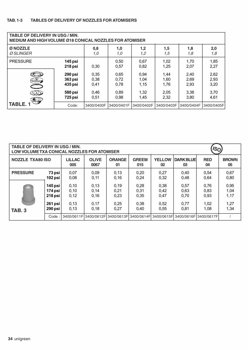
34 unigreen
TABLE OF DELIVERY IN USG / MIN.
LOW VOLUME TXA CONICAL NOZZLES FOR ATOMISER
NOZZLE TXA80 ISO LILLAC OLIVE ORANGE GREEM YELLOW DARK BLUE RED BROWN
005 0067 01 015 02 03 04 05
PRESSURE 73 psi 0,07 0,09 0,13 0,20 0,27 0,40 0,54 0,67102 psi 0,08 0,11 0,16 0,24 0,32 0,48 0,64 0,80
145 psi 0,10 0,13 0,19 0,28 0,38 0,57 0,76 0,95174 psi 0,10 0,14 0,21 0,31 0,42 0,63 0,83 1,04218 psi 0,12 0,16 0,23 0,35 0,47 0,70 0,93 1,17
261 psi 0,13 0,17 0,25 0,38 0,52 0,77 1,02 1,27290 psi 0,13 0,18 0,27 0,40 0,55 0,81 1,08 1,34
Code : 3400/0611F 3400/0612F 3400/0613F 3400/0614F 3400/0615F 3400/0616F 3400/0617F /
TAB. 3
ISO
TABLE OF DELIVERY IN USG / MIN.
MEDIUM AND HIGH VOLUME Ø18 CONICAL NOZZLES FOR ATOMISER
Ø NOZZLE 0,8 1,0 1,2 1,5 1,8 2,0
Ø SLINGER 1,0 1,0 1,2 1,5 1,8 1,8
PRESSURE 145 psi 0,50 0,67 1,02 1,70 1,85218 psi 0,30 0,57 0,82 1,25 2,07 2,27
290 psi 0,35 0,65 0,94 1,44 2,40 2,62363 psi 0,38 0,72 1,04 1,60 2,69 2,93435 psi 0,41 0,78 1,15 1,76 2,93 3,20
580 psi 0,46 0,89 1,32 2,05 3,38 3,70725 psi 0,51 0,98 1,45 2,32 3,80 4,61
Code: 3400/0400F 3400/0401F 3400/0402F 3400/0403F 3400/0404F 3400/0405FTABLE. 1
TAB. 1-3 TABLES OF DELIVERY OF NOZZLES FOR ATOMISERS

unigreen 35
TABLE OF DELIVERY IN USG / MIN. OF THE CONICAL NOZZLES FOR LEVER LANCE
note: standard Ø1,5 nozzle
DIAMETER NOZZLE Ø 1,0 Ø 1,2 Ø 1,5 Ø 1,75 Ø 2,0 Ø 2,2 Ø 2,5
PRESSURE (psi) JET CAPACITY (USG / min)
73 cone 0,31 0,37 0,50 0,59 0,70 0,77 0,92direct jet 0,37 0,45 0,66 1,04 1,24 1,59 2,03
116 cone 0,37 0,48 0,69 0,74 0,90 0,96 1,18direct jet 0,45 0,58 0,90 1,28 1,59 2,01 2,59
145 cone 0,40 0,52 0,77 0,82 1,03 1,08 1,32direct jet 0,50 0,63 0,99 1,43 1,84 2,26 2,91
218 cone 0,50 0,63 0,90 1,00 1,19 1,32 1,61direct jet 0,61 0,79 1,19 1,76 2,19 2,75 3,54
435 cone 0,69 0,90 1,27 1,43 1,66 1,88 2,30direct jet 0,85 1,11 1,69 2,48 3,09 3,88 5,05
725 cone 0,90 1,16 1,64 1,80 2,14 2,43 2,96direct jet 1,08 1,43 2,19 3,12 3,99 5,05 6,50
TABLE. 4
TAB. 4-5 TABLES OF DELIVERY OF NOZZLES FOR HAND LANCES
TABLE OF DELIVERY IN USG / MIN. OF THE CONICAL NOZZLES FOR MITRA SPRAY GUN
note: standard Ø2,5 nozzle
DIAMETER NOZZLE Ø 1,0 Ø 1,2 Ø 1,5 Ø 1,8 Ø 2,0 Ø 2,3 Ø 2,5 Ø 3,0
PRESSURE (psi) JET CAPACITY ( USG/min )
218 cone 0,65 0,95 1,22 1,56 1,82 2,14 2,43 3,04direct jet 0,66 1,00 1,35 1,93 2,32 2,85 3,43 4,86
363 cone 0,79 1,12 1,51 1,90 2,14 2,69 3,01 3,80direct jet 0,82 1,22 1,72 2,46 3,09 3,73 4,33 6,37
508 cone 0,90 1,24 1,74 2,25 2,69 3,41 3,70 4,76direct jet 0,92 1,43 1,96 2,85 3,54 4,44 5,05 7,45
580 cone 0,94 1,37 1,82 2,43 2,88 3,62 3,83 4,97direct jet 0,96 1,56 2,06 3,09 3,78 4,73 5,55 7,95
725 cone 1,06 1,48 2,03 2,77 3,30 3,94 4,33 5,52direct jet 1,08 1,66 2,27 3,36 4,17 5,20 6,08 8,72TABLE. 5

36 unigreen
TAB. 8 PROBLEMS, CAUSES AND SOLUTIONS
PROBLEMS CAUSES SOLUTIONS
The pump won’t charge Air suction Check the suction system
Adjustment valve closed Position the lever correctly(Command group isn’t atzero pressure)
Valves and/or valve seats Replace or clean ( * )suction and delivery wornor dirty
The pump doesn’t reach the set Valve and/or valve seat Replace ( * )pressure adjustment worn
Valves and/or valve seats suction Replace or clean ( * )and delivery worn or dirty
Insufficient rpm Bring speed up to correct rpmalways in the field of 350 ÷ 550 rpm.
The nozzles used are worn or have Replaceholes that are too big
Suction blocked Clean the cartridge of thefilter or remove the blockage
Irregular pressure (with impulses) Valves and/or valve seats Replace or clean ( * )suction and delivery wornor dirty
Air suction Check the suction system
Excessive vibrations at delivery Pressure accumulator discharged Bring the air pressure back up to the rightor incorrect air pressure value (see pump handbook) ( * )
Noisiness and the level of the oil Blocked suction Check the suction systemhas dropped
Water in the oil Breakage of one or more diaphragms Replace ( * ) If the replacement isn’tdone immediately, drain the water outof the pump and introduce clean oilwithout water (also used) or diesel tostop rust attacking the internalparts
No liquid comes out of the nozzles Delivery filter dirty CleanNon-drip filters dirtyNozzles blocked
NOTE: ( * ) Only specialised technician
TAB. 7 TABLE OF PROGRAMMED MAINTENANCE
OPERATION 8 h 50 h 300 h END
OF SEASON
Check the level and state of the oil 0Check the accumulator pressure 0Check the suction (hoses, pipes, unions) 0Check and clean the suction 0and delivery filtersCheck the pump fixing feet 0and screws in generalCheck the diaphragm and the oil X (1) X (2)and change if necessaryCheck the suction/delivery valves X XCheck the pump screws and bolts are tight XCheck and clean the nozzles and the non-drip diaphragm 0Check the wear of the nozzles 0Check the hydraulic oil level 0Check any failures or cracking of the welds, 0especially on herbicide boomsGrease the articulated joints and the wheel hubs 0Check the tyre pressure 0
NOTE: 0 Operation to be carried out by the operatorX Operation to be carried out by a specialised technician or in an authorised workshop(1) First oil change(2) Change at the same time a changing the diaphragm

unigreen 37
TAB.14A ALLOWED FITTINGS
2009 ATOMIZZATORI PORTATITYPE OF PLT
MACHINE Truck-mounted mistblowers
TAB. 14 aEXPO P EXPO A EXPO M KAMBA
FITTING CLIO P -AP P CLIO M - AP M VENUS - AP TOP150 201 301 402 300 400 600 202 302 410 402 402 600 600 800 300 400 600
FUN " " Ø500 NYLON X X X XGROUP " " Ø600 NYLON X X X X X X X X
" " Ø650 NYLON X X " " Ø700 NYLON X X " " Ø750 NYLON X " " Ø800 NYLON X X " " Ø800TV NYLON X X " " Ø800 JET X X X " " Ø450 CANNON
POMPE PUMP APS 41 X X X XCOMET " " APS 51 X X X X X X X
" " APS 71 X X X X X X X X " " APS 96 - IDS960 X X X " " APS 101 " " APS 121 X X X
PUMPS PUMP AR 30ANNOVI " " AR 503 X X X X X X X X XREVERBERI " " AR 813 - 903 X X X X X X X X X
" " AR 1064-1053 X X X X X " " AR 1265-1203 " " BHA 140
PISTON PUMP T 55PUMPS " " T 77PRESSURE GCP 3 WAY / Sirius X X X X X X X X X X XREGULATOR " RVA 2-4-5 WAY X X X X X X X X X X X X X X X X X X
" RM 40 S X X X X X X X X X X X X XGCP Electric X X X X X X X
JETS SINGLE NON-DRIP X X X X X X X X X X X X X X X X X XDOUBLE NON-DRIP X X X X X X X X X X X X X X X X X X
NOZZLES CERAM. CONICAL Ø 18 X X X X X X X X X X X X X X X X X XCERAM. CONICAL ISO X X X X X X X X X X X X X X X X X XALBUZ CERAM. ATR X X X X X X X X X X X X X X X X X XTOP DEF. X X X X X X X X X X X X X X X X X XHAND WASH X X X X X X X X X X X X X X X X X XCIRCUIT WASHER X X X X X X X X X X X X X XROT. IDR. 30°LEAF PROTECTION X X X X X X X X X X X X X X XSINGLE SIDE FOR OLIVES X X X X X X X X
WEIGHT EMPTY MAX FITINGS 120 160 190 190 190 210 270 134 200 270 230 230 260 260 420 232 260 350in Kg X10 FULL MAX FITINGS 284 390 540 630 570 680 970 362 550 750 730 730 990 990 1440 547 683 984P HP POWER NECESSARY 10 22 22 22 35 35 45 16 30 30 30 37 37 53 53 39 40 43

38 unigreen
TAB.15A ALLOWED FITTINGS
2007 ATOMIZZATORI PORTATI ATOMIZZATORI PORTATI con MOLTIPLICATORETYPE OF con PULEGGIA Tractor-mounted mistblowers with GEARBOXMACHINE Truck-mounted mistblowers
with BELT DRIVE
TAB. 15 a DEVIL - P DEVIL - TGZ SIRIO - EOLOFITTING AP-DP AP - TGZ AP - A
Nominal capacity 200 300 300 400 400 200 300 400 300 300 400 400 600FAN Sw ivel Ø600 NYLON TV X X XGROUP " " Ø650 NYLON X X
" " Ø700 NYLON TV X X " " Ø750 NYLON TV X " " Ø650 NY TGZ X X X X X
PUMPS " " APS 51 X X X X X X X X X X X XCOMET " " APS 71 X X X X X X X X X X X X X
" " APS 96 XPUMPS PUMP AR 503 X X X X X X X X X X X XANNOVI " " AR 813 - 903 X X X X X X X X X X X X XREVERBERI " " AR 1064 - 1053 XPRESSURE GCP RVA X X X X X X X X X X X X XREGULATOR ORION Comet X X X X X X X X X X X X X
GCP ELECTRIC X X X X X X X X X X X X X
JETS SINGLE NON-DRIP X X X X X X X X X X X X XDOUBLE NON-DRIPTRIPLE NON-DRIP X X X X X X X X X X X X X
NOZZLES CERAM. CONICAL Ø 18 X X X X X X X X X X X X XCERAM. CONICAL ISO X X X X X X X X X X X X XCERAM. CONICAL ATR X X X X X X X X X X X X XDEF. TOP X X X X X X X X X XTOP DEF. + 2 JETS X X X X X X X XHAND WASH X X X X X X X X X X X X XCIRCUIT WASHER X X X X X X X X X X X X XLEAF PROTECTION X X X X X X X X X X X X X
TOTAL MASS EMPTY MAX FITINGS 170 200 200 210 210 200 230 240 190 190 210 210 270in Kg FULL MAX FITINGS 430 580 580 690 690 460 610 700 560 560 680 680 970P HP POWER NECESSARY 35 35 40 35 40 45 45 45 35 35 35 35 50

unigreen 39
TAB.16A ALLOWED FITTINGS
2007 ATOMIZZATORI PORTATI A CANNONETYPE OF Tractor-mounted mistblowers "Cannon Type"
MACHINE
TAB. 16 aEOLO C - SIRIO C BORA - APCAPC APC
FITTINGNominal capacity (lt.) 300 400 600 600 800 800 1000 1000
FAN CENTRIFUGAL Ø450/27 X XGROUP " " Ø400 /38 X X X
" " Ø455 /75 X X X
PUMPS PUMP APS 51 X XCOMET " " APS 71 X X
" " APS 96 - IDS960 X X X " " APS121 X X X " " APS145 - IDS1401 X X X
PUMPS PUMP AR 503 X XANNOVI " " AR 813 - 903 X XREVERBERI " " AR 1064 - 1053 X X
" " AR 1265 - 1203 X X X X " " BHA 160 X X X
PRESSURE RVA X X X X X X X XREGULATOR ORION Comet X X X X X X
GCP ELECTRIC X X X X X XJETS P 39 X X
SINGLE NON-DRIP X X X X X X X XDOUBLE NON-DRIP X X X X X X X XTYRE MFC X X
NOZZLES CERAM. CONICAL X X X X X X X XCERAM. CONICAL ISO X X X X X X X XCERAM. CONICAL ATR X X X X X X X XCIRCUIT WASHER X X X X X X X XHAND WASH X X X X X X X XHYD. ROTAT 30° X X X X X X X XHYD. ROTAT. 70° X X X X X X X XHYD. ROTAT 180° X X X X X XSWIVEL HEAD X X X X X XHYD. HEAD X X X X X X
TOTAL MASS EMPTY MAX FITINGS 240 250 340 340 420 460 420 460in Kg FULL MAX FITINGS 620 720 810 1050 1380 1430 1580 1630P HP POWER NECESSARY 33 33 50 90 50 90 50 90

Descriptions, indicative illustrations, UNIGREEN S.P.A. reserves the right to make variations or modifications without prior warning.
via Rinaldi, 105 - 42124 Reggio Emilia - ITALY
Tel. +39 0522 369811
Fax. +39 0522 369898
e-mail: [email protected]
internet: www.unigreen-spa.com
member of the group
UN
I 16
1000
05F
- U
SA
Apr
-10