Embed Size (px)
Citation preview
Via M. Curie, 19 - Zona Ind. Ponte Rizzoli - 40064 Ozzano dell’Emilia (BO)
tel. : 051 79 50 80 - fax. : 051 79 93 37 e-mail: [email protected] - http: www.macfuge.com
MA
CF
UG
E2
51O
MM
3S
03-0
0 E
N
Use and Maintenance Manual Translation of the original: MACFUGE 251OMM3S03-00
Type: Centrifuge Separator with manual cleaning
Model: MACFUGE 251 OM M 3 S
Client:
Serial number:
Building year: 2016
2 Use e maintenance manual
MA
CF
UG
E2
51O
MM
3S
03-0
0 E
N
MACFUGE 251 OM M 3 S
3 Use e maintenance manual
MA
CF
UG
E2
51O
MM
3S
03-0
0 E
N
MACFUGE 251 OM M 3 S
FOREWORD
It is mandatory that the user reads and fully understands the present guide in all its parts
before using this machine.
The present guide is an integral part of the centrifugal separator and must be kept for future
reference until its disposal.
We would like to remind you that in order to keep information as clear as possible, we have
taken into consideration only foreseeable situations. Therefore directions do not concern
situations caused by an improper use of the separator and/or its tools.
The tampering of the electrical and electronic instruments without permission by Servizi In-
dustriali relieves Servizi Industriali itself from any liability with consequent cancella-
tion of any form of warranty.

4 Use e maintenance manual
MA
CF
UG
E2
51O
MM
3S
03-0
0 E
N
MACFUGE 251 OM M 3 S
5 Use e maintenance manual
MA
CF
UG
E2
51O
MM
3S
03-0
0 E
N
MACFUGE 251 OM M 3 S
Table of contents
Foreword pag. 3
Table of contents pag. 5
1 General information pag. 9
1.1 Guide’s content pag. 9
1.2 Warranty pag. 10
1.3 Changes to the separator’s features pag. 10
1.4 Notes for the preparation of the manual pag. 11
2 General Technical description pag. 13
2.1 General description pag. 13
2.2 Configurations pag. 15
2.3 Principle of operation pag. 16
2.3.1 Separator pag. 16
2.3.2 Concentrator pag. 17
2.3.3 Clarifier pag. 18
2.4 Solid phase discharge pag. 19
2.4.1 Manual discharge pag. 19
2.4.2 Automaric discharge pag. 20
2.4.3 Nozzle discharge pag. 22
2.4.3 Choosing the type of discharge pag. 24
2.5 Extraction of liquid phases pag. 25
2.5.1 Paring disks outlet pag. 25
2.5.2 Outlet by gravity pag. 26
2.6 Transmission of motion pag. 27
2.6.1 Mechanical gears pag. 27
2.6.2 Mechanicla belt pag. 27
2.7 Control panel pag. 28
2.8 Other components pag. 29
2.8.1 Inlet and outlet product pag. 29
2.8.2 Other devices and supplies pag. 29
2.8.3 Other devices and on request pag. 29
3 Safety pag. 31
3.1 Guidelines and rules applied pag. 31
3.2 General safety rules pag. 32
3.3 Purpose of use and Usage limits pag. 36
3.4 Continuous noise level and vibrations pag. 37
3.5 Identification label pag. 38
6 Use e maintenance manual
MA
CF
UG
E2
51O
MM
3S
03-0
0 E
N
MACFUGE 251 OM M 3 S
4 Handling and storage pag. 39
4.1 Handling pag. 39
4.2 Storageio pag. 42
5 Installation pag. 43
5.1 Machine base fixing pag. 43
5.1.1 Expansion anchor fixing pag. 43
5.1.2 Fixing to a metal frame pag. 46
5.1.3 Machine base assembly pag. 47
5.2 Separator assembly pag. 48
5.2.1 Lubrication pag. 48
6 Connections pag. 49
6.1 Product inlet/outlet pag. 50
6.1.1 Product inlet pag. 51
6.1.2 Light and heavy hase outlet pag. 51
6.1.3 Solid phase outlet pag. 52
6.2 Service water pag. 53
6.2.1 Maneuvre water pag. 54
6.2.2 ydraulic seal water pag. 54
6.2.3 Washing/fluidification water pag. 55
6.3 Drainage pag. 56
6.3.1 Maneuvre water drainage pag. 57
6.3.2 Safety drainage pag. 57
6.4 Electrical connections pag. 58
6.4.1 Installation of electrical panel pag. 58
6.4.2 Electrical connetction pag. 59
7 Usage and functioning pag. 63
7.1 Centrifuge use pag. 64
7.2 Starting pag. 65
7.3 Stop pag. 66
7.4 Centrifuge regulation pag. 67
7.4.1 Regulation of the separation pag. 68
7.4.1 manual discharge of solids pag. 73
8 Tecnical Data Sheet pag. 75
8.1 Centrifuge configuration pag. 75
8.2 Tecnical Data pag. 76
8.3 Electrical absorption pag. 77
8.4 Diagram of adjustment ring pag. 78
7 Use e maintenance manual
MA
CF
UG
E2
51O
MM
3S
03-0
0 E
N
MACFUGE 251 OM M 3 S
9 Troubleshooting pag. 79
10 Maintenance pag. 81
10.1 Lubrification oil change pag. 83
10.2 Outlet - covers group pag. 84
10.2.1 Outlet and cover group disassembly pag. 84
10.2.2 Periodical maintenance and inspections pag. 87
10.3 Bowl group pag. 88
10.3.1 Bowl group disassembly pag. 88
10.3.2 Bowl cleaning pag. 95
10.3.3 Maintenance and periodical inspections pag. 97
10.4 Collar - vertical shaft group pag. 99
10.4.1 Collar group disassembly pag. 99
10.4.2 Maintenance and periodical inspections pag. 101
10.5 Horizontal shaft group pag. 102
10.5.1 Horizontal group disassembly pag. 102
10.5.2 Maintenance and periodical inspections pag. 105
10.6 Maintenance and scheduled inspections pag. 106
11 Demolition pag. 107
12 Parts list pag. 109
12.1 Variation parts list pag. 109
12.2 Machine group pag. 110
Tav.1 horizontal shaft group pag. 112
Tav.2 vertical shaft group pag. 114
Tav.3 collar group pag. 116
Tav.4 covers group pag. 118
Tav.5 bowl group pag. 120
Tav.6 outlets group pag. 122
Tav.7 tools group pag. 124
Tav.8 pocker loss tank group pag. 126
13 Parts’s list pag. 129
13.1 Replacements prescribed pag. 129
13.2 Spare parts’ order form pag. 131
14 Variations pag. 133
15 Riepilogo interventi di manutenzione pag. 135
8 Use e maintenance manual
MA
CF
UG
E2
51O
MM
3S
03-0
0 E
N
MACFUGE 251 OM M 3 S
The following documents are attached to the guide, when applicable:
Declaration of compliance
Attachment A System and components plan (P&ID)
Attachment A1 Dimensions and weight
Attachment A2 Connections
Attachment B Electrical diagram
Attachment C Internal commissioning test
Attachment D Materials’ certificates
Attachment E Electrical motor guide
Attachments Components’ guides and certificates
9 Use e maintenance manual
MA
CF
UG
E2
51O
MM
3S
03-0
0 E
N
MACFUGE 251 OM M 3 S
1 GENERAL INFORMATION
1 GENERAL INFORMATION
1.1 GUIDE’S CONTENT
Acknowledged that it is mandatory that the user reads and fully understands the present
guide in all its parts before using this machine and that the present guide is an integral part
of the centrifugal separator and must be kept for future reference until its disposal, we now
describe the guide’s content and its consultation methodology.
This booklet titled “USE AND CARE GUIDE” provides all the necessary information to
correctly perform all the installation, commissioning and maintenance procedures related to
the centrifugal separator, object of the present manual.
The guide is divided in chapters, and the table of contents, in the initial pages, speeds up
the consultation. The chapters’ order reflects the order of the procedures to be performed;
therefore the information provided starts from separator installment, assembly of the bulk
parts, start-up, usage adjustments, maintenance and replacements.
The following abbreviations are used in the guide:
Pg. = Page,
Fig. = Figure,
Tab. = Table,
Ref. = Reference,
Ch. = Chapter,
Par. = Paragraph
Tab. = Spare parts table.
Att. = Attachment
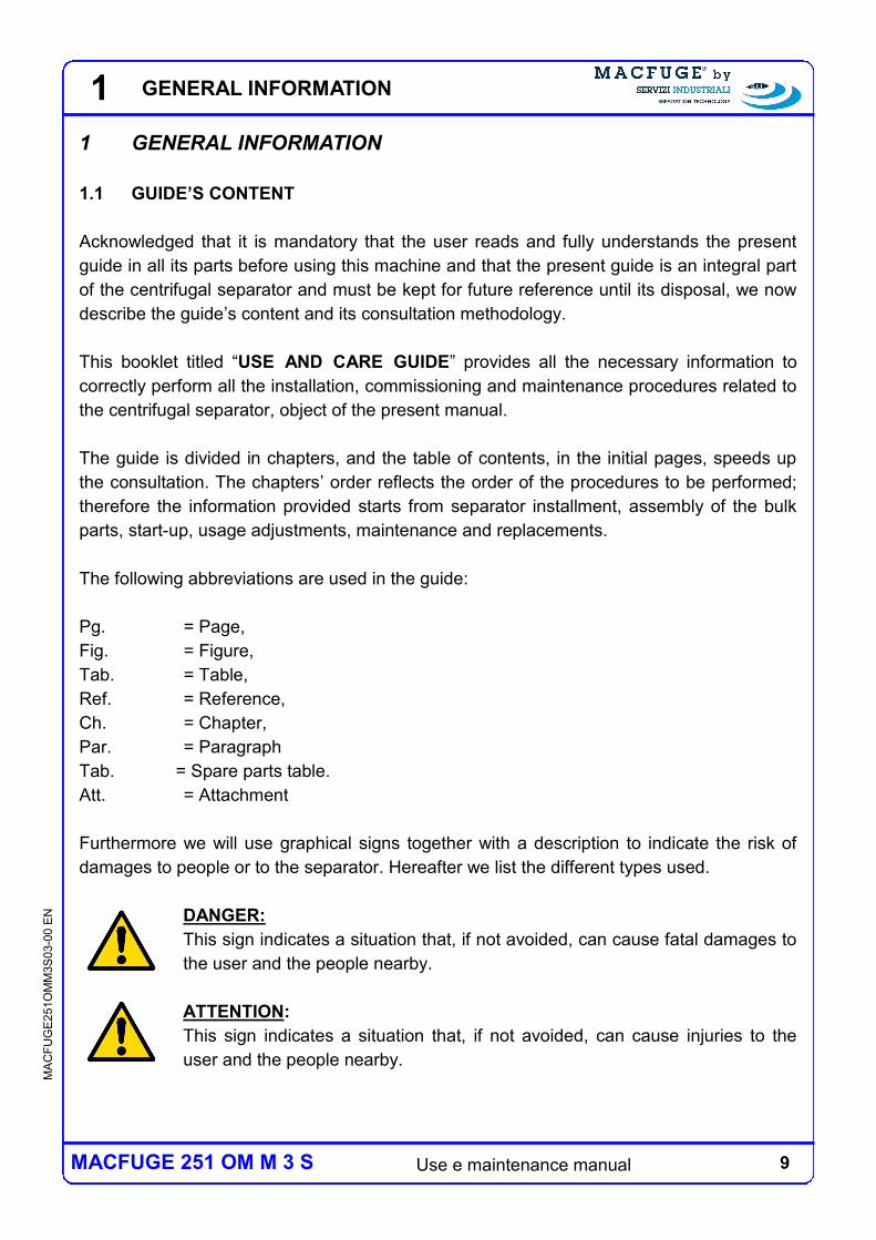
Furthermore we will use graphical signs together with a description to indicate the risk of
damages to people or to the separator. Hereafter we list the different types used.
DANGER:
This sign indicates a situation that, if not avoided, can cause fatal damages to
the user and the people nearby.
ATTENTION:
This sign indicates a situation that, if not avoided, can cause injuries to the
user and the people nearby.
10 Use e maintenance manual
MA
CF
UG
E2
51O
MM
3S
03-0
0 E
N
MACFUGE 251 OM M 3 S
1 GENERAL INFORMATION
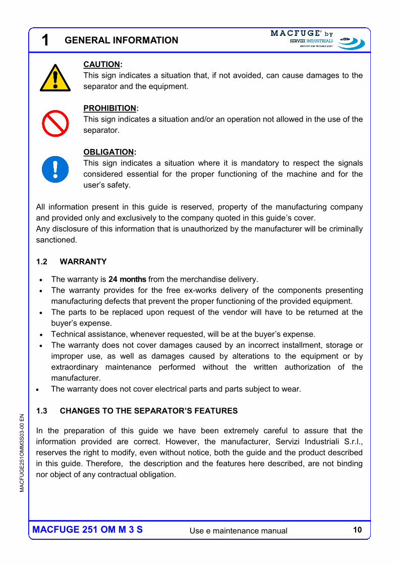
CAUTION:
This sign indicates a situation that, if not avoided, can cause damages to the
separator and the equipment.
PROHIBITION:
This sign indicates a situation and/or an operation not allowed in the use of the
separator.
OBLIGATION:
This sign indicates a situation where it is mandatory to respect the signals
considered essential for the proper functioning of the machine and for the
user’s safety.
All information present in this guide is reserved, property of the manufacturing company
and provided only and exclusively to the company quoted in this guide’s cover.
Any disclosure of this information that is unauthorized by the manufacturer will be criminally
sanctioned.
1.2 WARRANTY
The warranty is 24 months from the merchandise delivery.
The warranty provides for the free ex-works delivery of the components presenting
manufacturing defects that prevent the proper functioning of the provided equipment.
The parts to be replaced upon request of the vendor will have to be returned at the
buyer’s expense.
Technical assistance, whenever requested, will be at the buyer’s expense.
The warranty does not cover damages caused by an incorrect installment, storage or
improper use, as well as damages caused by alterations to the equipment or by
extraordinary maintenance performed without the written authorization of the
manufacturer.
The warranty does not cover electrical parts and parts subject to wear.
1.3 CHANGES TO THE SEPARATOR’S FEATURES
In the preparation of this guide we have been extremely careful to assure that the
information provided are correct. However, the manufacturer, Servizi Industriali S.r.l.,
reserves the right to modify, even without notice, both the guide and the product described
in this guide. Therefore, the description and the features here described, are not binding
nor object of any contractual obligation.
11 Use e maintenance manual
MA
CF
UG
E2
51O
MM
3S
03-0
0 E
N
MACFUGE 251 OM M 3 S
1 GENERAL INFORMATION
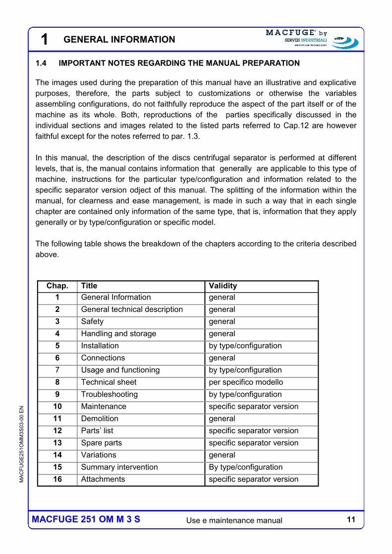
1.4 IMPORTANT NOTES REGARDING THE MANUAL PREPARATION
The images used during the preparation of this manual have an illustrative and explicative
purposes, therefore, the parts subject to customizations or otherwise the variables
assembling configurations, do not faithfully reproduce the aspect of the part itself or of the
machine as its whole. Both, reproductions of the parties specifically discussed in the
individual sections and images related to the listed parts referred to Cap.12 are however
faithful except for the notes referred to par. 1.3.
In this manual, the description of the discs centrifugal separator is performed at different
levels, that is, the manual contains information that generally are applicable to this type of
machine, instructions for the particular type/configuration and information related to the
specific separator version odject of this manual. The splitting of the information within the
manual, for clearness and ease management, is made in such a way that in each single
chapter are contained only information of the same type, that is, information that they apply
generally or by type/configuration or specific model.
The following table shows the breakdown of the chapters according to the criteria described
above.
Chap. Validity Title
1 general General Information
2 general General technical description
3 general Safety
4 general Handling and storage
5 by type/configuration Installation
6 general Connections
7 by type/configuration Usage and functioning
8 per specifico modello Technical sheet
9 by type/configuration Troubleshooting
10 specific separator version Maintenance
11 general Demolition
12 specific separator version Parts’ list
13 specific separator version Spare parts
14 general Variations
15 By type/configuration Summary intervention
16 specific separator version Attachments
12 Use e maintenance manual
MA
CF
UG
E2
51O
MM
3S
03-0
0 E
N
MACFUGE 251 OM M 3 S
1 GENERAL INFORMATION
13 Use e maintenance manual
MA
CF
UG
E2
51O
MM
3S
03-0
0 E
N
MACFUGE 251 OM M 3 S
2 GENERAL TECHNICAL DESCRIPTION
2.1 GENERAL DESCRIPTION
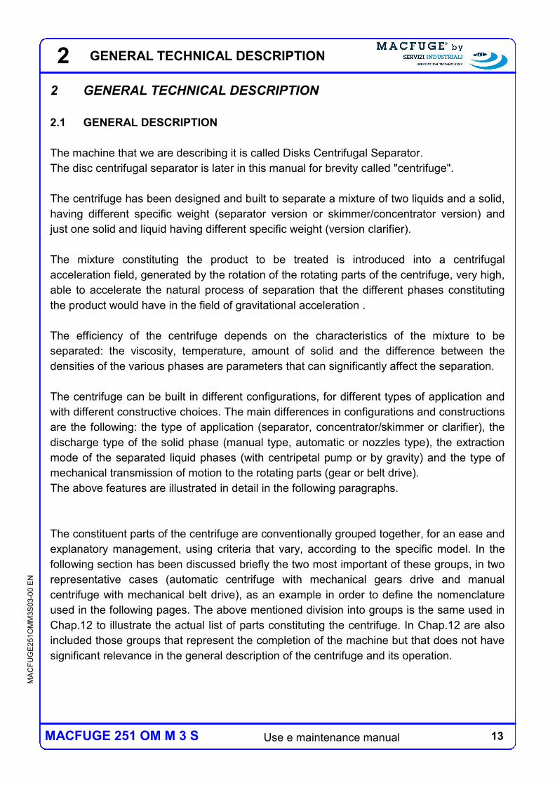
The machine that we are describing it is called Disks Centrifugal Separator.
The disc centrifugal separator is later in this manual for brevity called "centrifuge".
The centrifuge has been designed and built to separate a mixture of two liquids and a solid,
having different specific weight (separator version or skimmer/concentrator version) and
just one solid and liquid having different specific weight (version clarifier).
The mixture constituting the product to be treated is introduced into a centrifugal
acceleration field, generated by the rotation of the rotating parts of the centrifuge, very high,
able to accelerate the natural process of separation that the different phases constituting
the product would have in the field of gravitational acceleration .
The efficiency of the centrifuge depends on the characteristics of the mixture to be
separated: the viscosity, temperature, amount of solid and the difference between the
densities of the various phases are parameters that can significantly affect the separation.
The centrifuge can be built in different configurations, for different types of application and
with different constructive choices. The main differences in configurations and constructions
are the following: the type of application (separator, concentrator/skimmer or clarifier), the
discharge type of the solid phase (manual type, automatic or nozzles type), the extraction
mode of the separated liquid phases (with centripetal pump or by gravity) and the type of
mechanical transmission of motion to the rotating parts (gear or belt drive).
The above features are illustrated in detail in the following paragraphs.
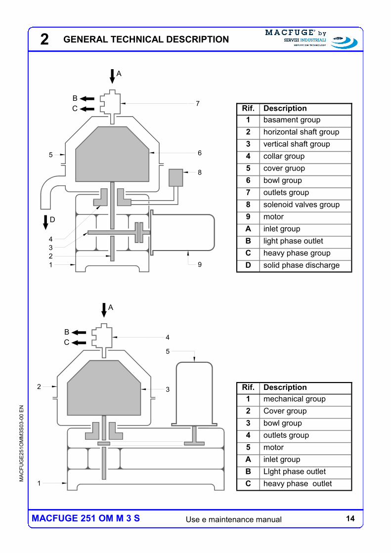
The constituent parts of the centrifuge are conventionally grouped together, for an ease and
explanatory management, using criteria that vary, according to the specific model. In the
following section has been discussed briefly the two most important of these groups, in two
representative cases (automatic centrifuge with mechanical gears drive and manual
centrifuge with mechanical belt drive), as an example in order to define the nomenclature
used in the following pages. The above mentioned division into groups is the same used in
Chap.12 to illustrate the actual list of parts constituting the centrifuge. In Chap.12 are also
included those groups that represent the completion of the machine but that does not have
significant relevance in the general description of the centrifuge and its operation.
2 GENERAL TECHNICAL DESCRIPTION
14 Use e maintenance manual
MA
CF
UG
E2
51O
MM
3S
03-0
0 E
N
MACFUGE 251 OM M 3 S
A
B
C
D
4
3
2
1
8
9
7
5 6
Rif. Description
1 basament group
2 horizontal shaft group
3 vertical shaft group
4 collar group
5 cover gruop
6 bowl group
7 outlets group
8 solenoid valves group
9 motor
A inlet group
B light phase outlet
C heavy phase group
D solid phase discharge
A
B
C
3
4
5
1
2 Rif. Description
1 mechanical group
2 Cover group
3 bowl group
4 outlets group
5 motor
A inlet group
B Llght phase outlet
C heavy phase outlet
2 GENERAL TECHNICAL DESCRIPTION
15 Use e maintenance manual
MA
CF
UG
E2
51O
MM
3S
03-0
0 E
N
MACFUGE 251 OM M 3 S
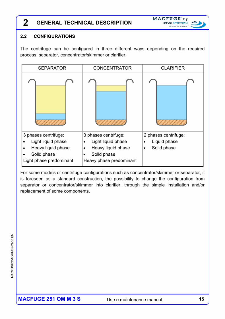
2.2 CONFIGURATIONS
The centrifuge can be configured in three different ways depending on the required
process: separator, concentrator/skimmer or clarifier.
For some models of centrifuge configurations such as concentrator/skimmer or separator, it
is foreseen as a standard construction, the possibility to change the configuration from
separator or concentrator/skimmer into clarifier, through the simple installation and/or
replacement of some components.
SEPARATOR CONCENTRATOR CLARIFIER
3 phases centrifuge:
Light liquid phase
Heavy liquid phase
Solid phase
Light phase predominant
3 phases centrifuge:
Light liquid phase
Heavy liquid phase
Solid phase
Heavy phase predominant
2 phases centrifuge:
Liquid phase
Solid phase
2 GENERAL TECHNICAL DESCRIPTION
16 Use e maintenance manual
MA
CF
UG
E2
51O
MM
3S
03-0
0 E
N
MACFUGE 251 OM M 3 S
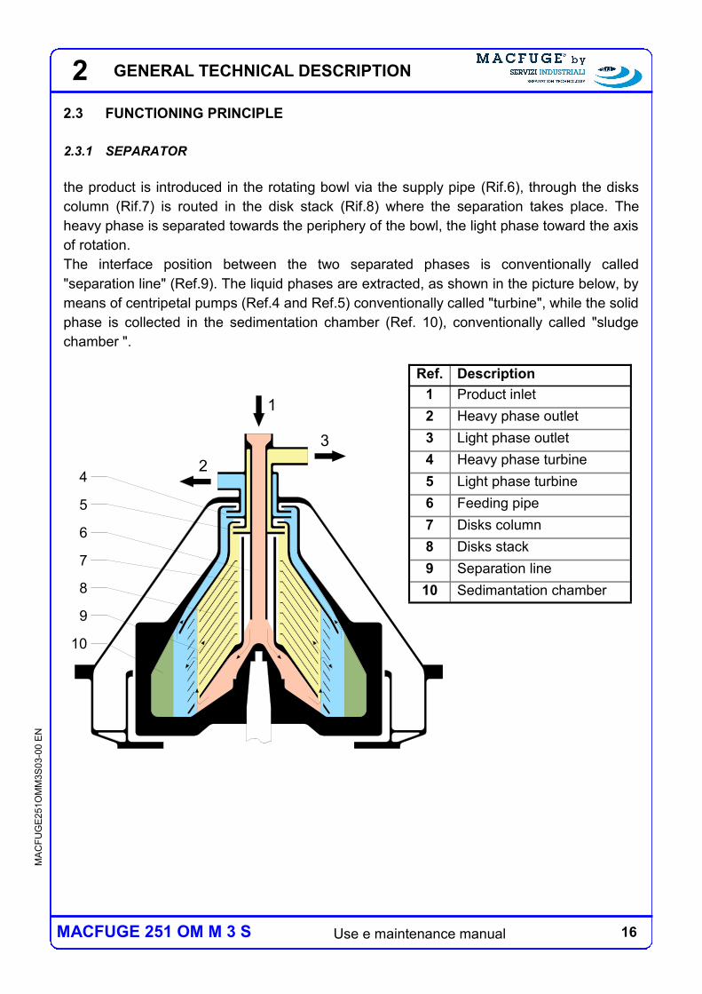
2.3 FUNCTIONING PRINCIPLE
2.3.1 SEPARATOR
the product is introduced in the rotating bowl via the supply pipe (Rif.6), through the disks
column (Rif.7) is routed in the disk stack (Rif.8) where the separation takes place. The
heavy phase is separated towards the periphery of the bowl, the light phase toward the axis
of rotation.
The interface position between the two separated phases is conventionally called
"separation line" (Ref.9). The liquid phases are extracted, as shown in the picture below, by
means of centripetal pumps (Ref.4 and Ref.5) conventionally called "turbine", while the solid
phase is collected in the sedimentation chamber (Ref. 10), conventionally called "sludge
chamber ".
2
2
1
3
4
5
6
7
8
9
10
Ref. Description
1 Product inlet
2 Heavy phase outlet
3 Light phase outlet
4 Heavy phase turbine
5 Light phase turbine
6 Feeding pipe
7 Disks column
8 Disks stack
9 Separation line
10 Sedimantation chamber
GENERAL TECHNICAL DESCRIPTION
17 Use e maintenance manual
MA
CF
UG
E2
51O
MM
3S
03-0
0 E
N
MACFUGE 251 OM M 3 S
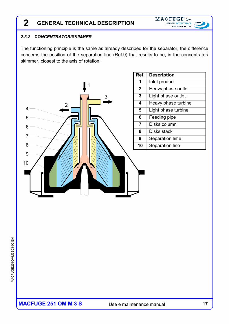
2.3.2 CONCENTRATOR/SKIMMER
The functioning principle is the same as already described for the separator, the difference
concerns the position of the separation line (Ref.9) that results to be, in the concentrator/
skimmer, closest to the axis of rotation.
2
2
1
3
4
5
6
7
8
9
10
Ref. Description
1 Inlet product
2 Heavy phase outlet
3 Light phase outlet
4 Heavy phase turbine
5 Light phase turbine
6 Feeding pipe
7 Disks column
8 Disks stack
9 Separation lime
10 Separation line
GENERAL TECHNICAL DESCRIPTION
18 Use e maintenance manual
MA
CF
UG
E2
51O
MM
3S
03-0
0 E
N
MACFUGE 251 OM M 3 S
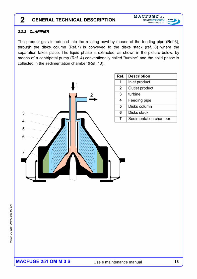
2.3.3 CLARIFIER
The product gets introduced into the rotating bowl by means of the feeding pipe (Ref.6),
through the disks column (Ref.7) is conveyed to the disks stack (ref. 8) where the
separation takes place. The liquid phase is extracted, as shown in the picture below, by
means of a centripetal pump (Ref. 4) conventionally called "turbine" and the solid phase is
collected in the sedimentation chamber (Ref. 10).
2
1
2
3
4
5
6
7
Ref. Description
1 Inlet product
2 Outlet product
3 turbine
4 Feeding pipe
5 Disks column
6 Disks stack
7 Sedimentation chamber
GENERAL TECHNICAL DESCRIPTION
19 Use e maintenance manual
MA
CF
UG
E2
51O
MM
3S
03-0
0 E
N
MACFUGE 251 OM M 3 S
1
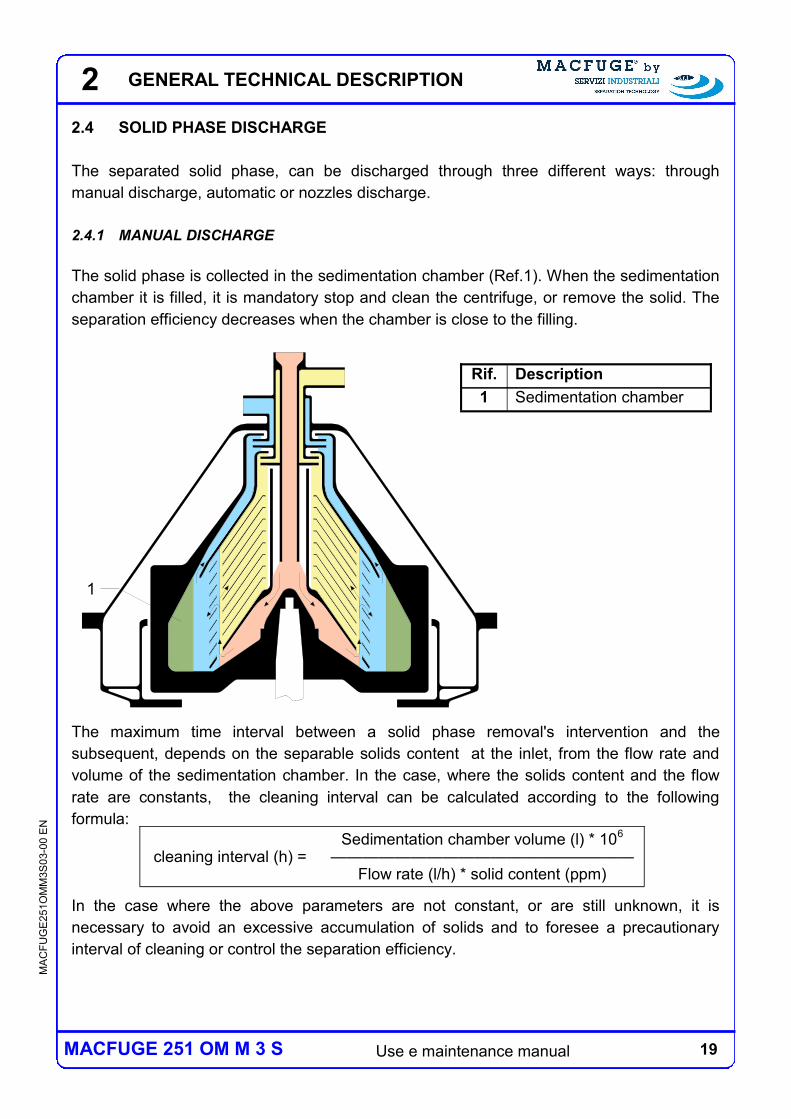
2.4 SOLID PHASE DISCHARGE
The separated solid phase, can be discharged through three different ways: through
manual discharge, automatic or nozzles discharge.
2.4.1 MANUAL DISCHARGE
The solid phase is collected in the sedimentation chamber (Ref.1). When the sedimentation
chamber it is filled, it is mandatory stop and clean the centrifuge, or remove the solid. The
separation efficiency decreases when the chamber is close to the filling.
The maximum time interval between a solid phase removal's intervention and the
subsequent, depends on the separable solids content at the inlet, from the flow rate and
volume of the sedimentation chamber. In the case, where the solids content and the flow
rate are constants, the cleaning interval can be calculated according to the following
formula:
In the case where the above parameters are not constant, or are still unknown, it is
necessary to avoid an excessive accumulation of solids and to foresee a precautionary
interval of cleaning or control the separation efficiency.
2
cleaning interval (h) = Sedimentation chamber volume (l) * 10
6
——————————————————— Flow rate (l/h) * solid content (ppm)
Rif. Description
1 Sedimentation chamber
GENERAL TECHNICAL DESCRIPTION
20 Use e maintenance manual
MA
CF
UG
E2
51O
MM
3S
03-0
0 E
N
MACFUGE 251 OM M 3 S
53 4
2
1
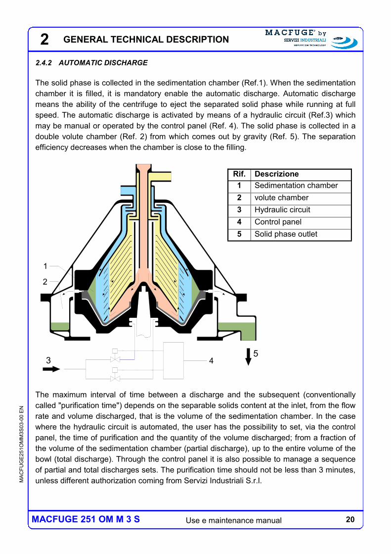
2.4.2 AUTOMATIC DISCHARGE
The solid phase is collected in the sedimentation chamber (Ref.1). When the sedimentation
chamber it is filled, it is mandatory enable the automatic discharge. Automatic discharge
means the ability of the centrifuge to eject the separated solid phase while running at full
speed. The automatic discharge is activated by means of a hydraulic circuit (Ref.3) which
may be manual or operated by the control panel (Ref. 4). The solid phase is collected in a
double volute chamber (Ref. 2) from which comes out by gravity (Ref. 5). The separation
efficiency decreases when the chamber is close to the filling.
The maximum interval of time between a discharge and the subsequent (conventionally
called "purification time") depends on the separable solids content at the inlet, from the flow
rate and volume discharged, that is the volume of the sedimentation chamber. In the case
where the hydraulic circuit is automated, the user has the possibility to set, via the control
panel, the time of purification and the quantity of the volume discharged; from a fraction of
the volume of the sedimentation chamber (partial discharge), up to the entire volume of the
bowl (total discharge). Through the control panel it is also possible to manage a sequence
of partial and total discharges sets. The purification time should not be less than 3 minutes,
unless different authorization coming from Servizi Industriali S.r.l.
2
Rif. Descrizione
1 Sedimentation chamber
2 volute chamber
3 Hydraulic circuit
4 Control panel
5 Solid phase outlet
GENERAL TECHNICAL DESCRIPTION
21 Use e maintenance manual
MA
CF
UG
E2
51O
MM
3S
03-0
0 E
N
MACFUGE 251 OM M 3 S
2
In the case, where the solids content and the flow rate are constants, the cleaning interval
can be calculated according to the following formula:
In the case where the above parameters are not constant, or are still unknown, it is
necessary to avoid an excessive accumulation of solids and to foresee a precautionary
purification time or control the separation efficiency.
In the case where total discharges are executed or it is necessary to restore the hydraulics
seal pocket after discharging(see note), it is necessary to stop the feeding of product to the
centrifuge during the discharge phase. The effective flow rate of the centrifuge after the
above mentioned inactive phase, can be calculated according to the following formula:
Note: The hydraulic seal pocket is the necessary filling of the sedimentation chamber with
the heavy phase before the to feed the centrifuge with the product, you will see in the
following pages.
Purification time (min.) = Volume discharged (l) * 6000
————————————————— Flow rate (l/h) * solid content(%)
effective flow rate (l/h) =
Flow rate (l/h) * depuration time (min.) * 60 ——————————————————————
Depuration time (min.)* 60 + inactive phase (s)
GENERAL TECHNICAL DESCRIPTION
22 Use e maintenance manual
MA
CF
UG
E2
51O
MM
3S
03-0
0 E
N
MACFUGE 251 OM M 3 S
2
4
3
2
1
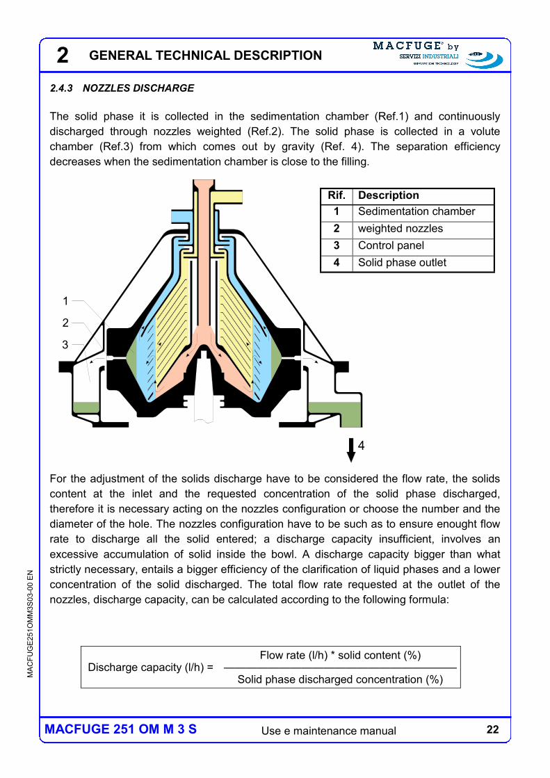
2.4.3 NOZZLES DISCHARGE
The solid phase it is collected in the sedimentation chamber (Ref.1) and continuously
discharged through nozzles weighted (Ref.2). The solid phase is collected in a volute
chamber (Ref.3) from which comes out by gravity (Ref. 4). The separation efficiency
decreases when the sedimentation chamber is close to the filling.
For the adjustment of the solids discharge have to be considered the flow rate, the solids
content at the inlet and the requested concentration of the solid phase discharged,
therefore it is necessary acting on the nozzles configuration or choose the number and the
diameter of the hole. The nozzles configuration have to be such as to ensure enought flow
rate to discharge all the solid entered; a discharge capacity insufficient, involves an
excessive accumulation of solid inside the bowl. A discharge capacity bigger than what
strictly necessary, entails a bigger efficiency of the clarification of liquid phases and a lower
concentration of the solid discharged. The total flow rate requested at the outlet of the
nozzles, discharge capacity, can be calculated according to the following formula:
Discharge capacity (l/h) = Flow rate (l/h) * solid content (%)
————————————————————— Solid phase discharged concentration (%)
Rif. Description
1 Sedimentation chamber
2 weighted nozzles
3 Control panel
4 Solid phase outlet
GENERAL TECHNICAL DESCRIPTION
23 Use e maintenance manual
MA
CF
UG
E2
51O
MM
3S
03-0
0 E
N
MACFUGE 251 OM M 3 S
2
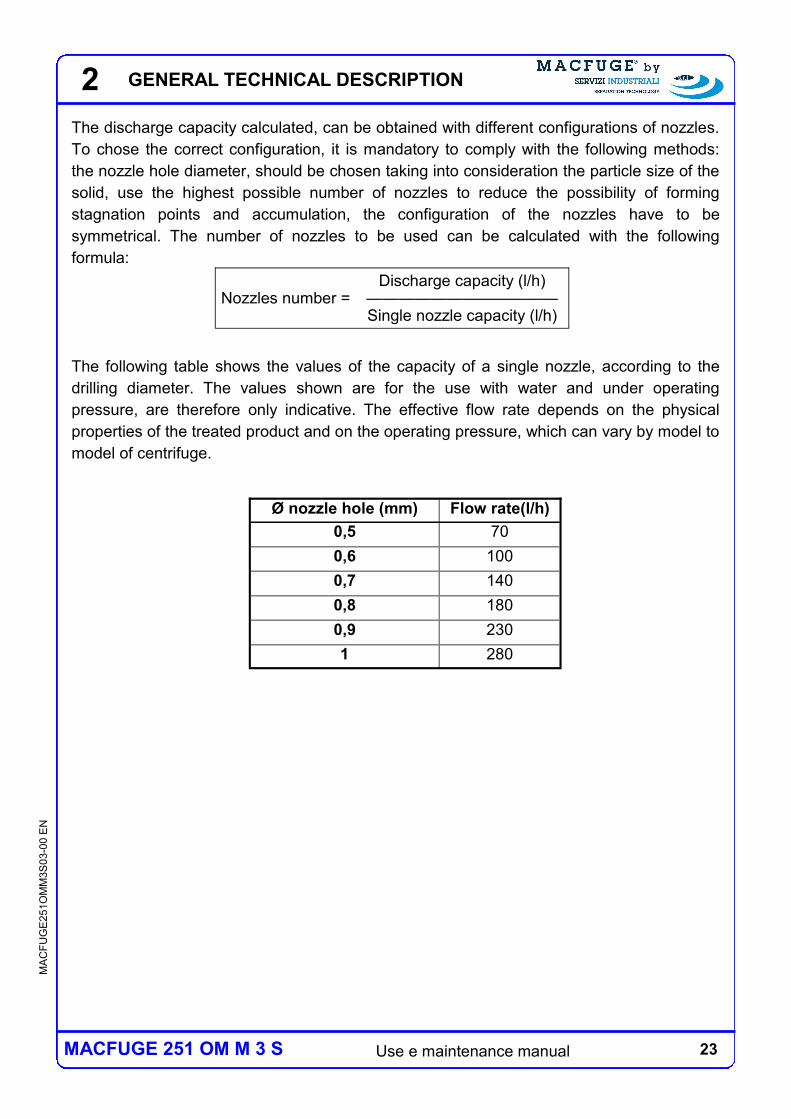
The discharge capacity calculated, can be obtained with different configurations of nozzles.
To chose the correct configuration, it is mandatory to comply with the following methods:
the nozzle hole diameter, should be chosen taking into consideration the particle size of the
solid, use the highest possible number of nozzles to reduce the possibility of forming
stagnation points and accumulation, the configuration of the nozzles have to be
symmetrical. The number of nozzles to be used can be calculated with the following
formula:
The following table shows the values of the capacity of a single nozzle, according to the
drilling diameter. The values shown are for the use with water and under operating
pressure, are therefore only indicative. The effective flow rate depends on the physical
properties of the treated product and on the operating pressure, which can vary by model to
model of centrifuge.
Nozzles number = Discharge capacity (l/h)
———————————— Single nozzle capacity (l/h)
Ø nozzle hole (mm) Flow rate(l/h)
0,5 70
0,6 100
0,7 140
0,8 180
0,9 230
1 280
GENERAL TECHNICAL DESCRIPTION
24 Use e maintenance manual
MA
CF
UG
E2
51O
MM
3S
03-0
0 E
N
MACFUGE 251 OM M 3 S
2
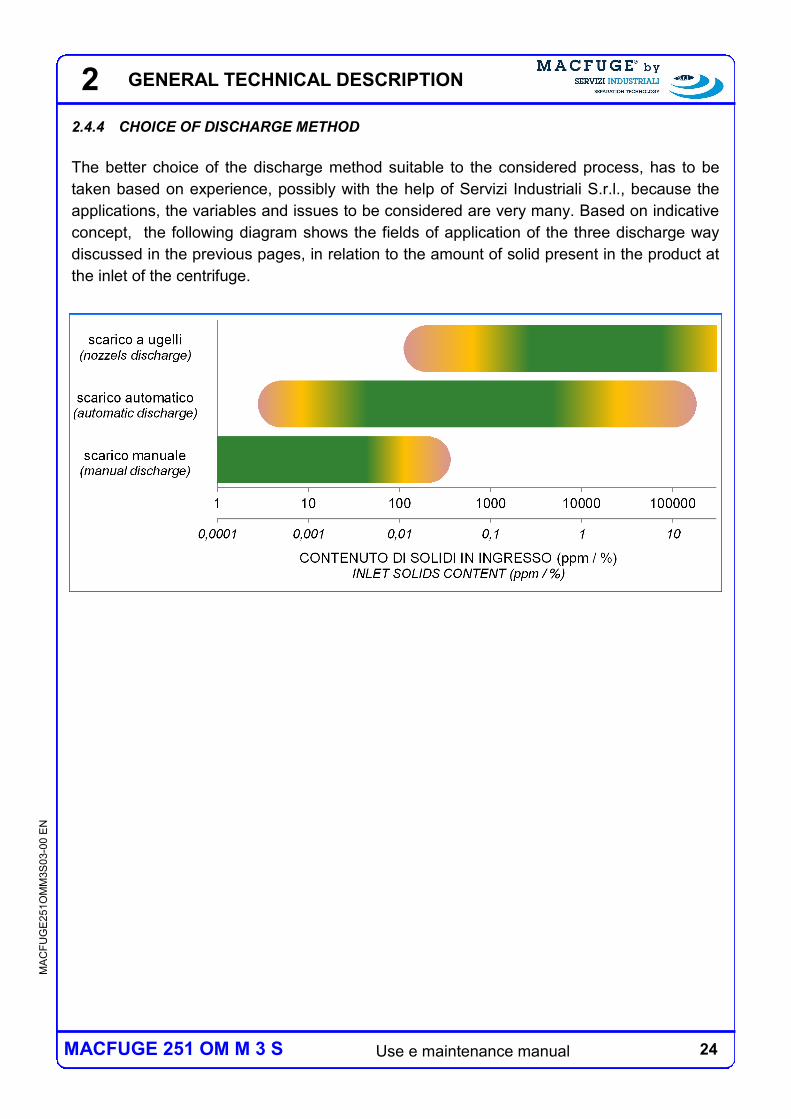
2.4.4 CHOICE OF DISCHARGE METHOD
The better choice of the discharge method suitable to the considered process, has to be
taken based on experience, possibly with the help of Servizi Industriali S.r.l., because the
applications, the variables and issues to be considered are very many. Based on indicative
concept, the following diagram shows the fields of application of the three discharge way
discussed in the previous pages, in relation to the amount of solid present in the product at
the inlet of the centrifuge.
GENERAL TECHNICAL DESCRIPTION
25 Use e maintenance manual
MA
CF
UG
E2
51O
MM
3S
03-0
0 E
N
MACFUGE 251 OM M 3 S
2
1
2
3
2.5 EXTRACTION OF LIQUID PHASES
The separated liquid phases can be extracted in two different ways: with centripetal pump,
conventionally called "turbine", or by gravity. In the remainder of this manual will be used
respectively the conventional expressions "turbine outlet" and "outlet by gravity".
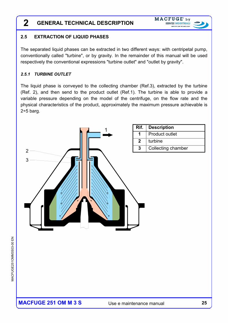
2.5.1 TURBINE OUTLET
The liquid phase is conveyed to the collecting chamber (Ref.3), extracted by the turbine
(Ref. 2), and then send to the product outlet (Ref.1). The turbine is able to provide a
variable pressure depending on the model of the centrifuge, on the flow rate and the
physical characteristics of the product, approximately the maximum pressure achievable is
2÷5 barg.
Rif. Description
1 Product outlet
2 turbine
3 Collecting chamber
GENERAL TECHNICAL DESCRIPTION
26 Use e maintenance manual
MA
CF
UG
E2
51O
MM
3S
03-0
0 E
N
MACFUGE 251 OM M 3 S
2
1
2
3
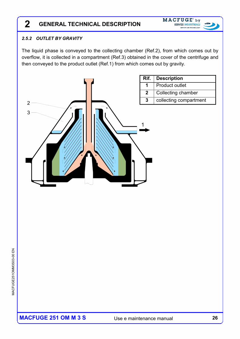
2.5.2 OUTLET BY GRAVITY
The liquid phase is conveyed to the collecting chamber (Ref.2), from which comes out by
overflow, it is collected in a compartment (Ref.3) obtained in the cover of the centrifuge and
then conveyed to the product outlet (Ref.1) from which comes out by gravity.
Rif. Description
1 Product outlet
2 Collecting chamber
3 collecting compartment
GENERAL TECHNICAL DESCRIPTION
27 Use e maintenance manual
MA
CF
UG
E2
51O
MM
3S
03-0
0 E
N
MACFUGE 251 OM M 3 S
2
2.6 MOTION TRANSMISSION
The centrifuge is moved by an electric motor. The transmission of the motion to the rotating
parts can be done in two ways: by means gears drive with orthogonal axes (with torque
wheel / pinion with helical teeth) or by means of pulleys and belt drive.
2.6.1 GEAR DRIVE
The centrifuge is moved by an electric motor driven by a frequency converter. Through an
elastic connection the motion is transmitted to the horizontal shaft, then, to the vertical shaft
through the coupling of wheel / pignon with ratio multiplier. The vertical shaft is elastically
supported in both radial and axial direction. The bearings and gears are lubricated by
splash of oil.
2.6.2 BELT DRIVE
The centrifuge is moved by an electric motor which can be direct starter for centrifuges of
smaller size, or driven by a frequency converter for centrifuges of larger size. For the
gradual start up of the centrifuge, in alternative or in substitution to the frequency converter,
in some models of centrifuge, it is used a mechanical clutch. Through a couple of pulleys,
with a ratio multiplier and a belt drive, the motion is transmitted to the shaft vertical. The
vertical shaft is elastically supported in both radial and axial direction. The bearings can be
lubricated by splash oil or not require additional lubrication.
GENERAL TECHNICAL DESCRIPTION
28 Use e maintenance manual
MA
CF
UG
E2
51O
MM
3S
03-0
0 E
N
MACFUGE 251 OM M 3 S
2
2.7 ELECTRICAL CONTROL PANEL
The centrifuge can be supplied with an electrical control panel.
In the case which the centrifuge is not supplied with electrical control panel it
is necessary that the user get in contact with Servizi Industriali S.r.l. for the
definition of the aforesaid and in any case comply with the specifications
described in this manual.
In the case of the solid bowl centrifuge (manual cleaning type), the electrical control panel
allows to start and stop the centrifuge. The control panel can also be prepared to manage a
number of ancillary devices, available on request: feeding pump, water pocket alarm loss,
frequency converter, etc.
In the case of the automatic centrifuge (self cleaning centrifgue) the electrical control panel
completed with PLC, controls the entire cycle of the centrifuge: start up, operation working
(separation, partial discharges, total discharges), stop. The software of the control panel it
is also prepared to manage a number of ancillary devices available on request: evacuation
pump and level switches for the tank of the solids discharged, water maneuvering pump,
frequency converter, etc.
Cap.7 describes the main functional characteristics of the electrical control panel of both
solid bowl centrifuge and self cleaning centrifuge. The foreseen functions may being
different, especially for what concerns the management of any devices supplied requested.
For the specific definition of the electrical control panel and its functions, you will therefore
refer to the wiring diagram of this manual (All.B).
GENERAL TECHNICAL DESCRIPTION
29 Use e maintenance manual
MA
CF
UG
E2
51O
MM
3S
03-0
0 E
N
MACFUGE 251 OM M 3 S
2
2.8 OTHERS COMPONENTS
2.8.1 INLET AND OUTLET PRODUCT
The inlets and product outlet lines, are supplied with components that may vary according
to the model and configuration of the centrifuge, in accordance with specific customer
requests (eg. for the connections type) or according to necessities arising from the specific
process. In addition to the flexible hoses, that can be provided or not but nevertheless
necessary, the main components that are frequently provided are: sight glass, sampling,
manual valves, pressure control and pressure gauges.
2.8.2 OTHER STANDARD DEVICES AND SUPPLIES
All centrifuge models are provided as standard of common tools and special wrenches
required for the assembly and disassembly of the centrifuge, as well as spare parts for
prompt intervention also needed for the commissioning of the centrifuge. Other devices
which are designed specifically for some models of centrifuge are as follows: feeding pump
of the product with its protective filter, water pocket loss alarm system, soundproofing/
insulation covers , washing / cooling covers, fluidification of the heavy phase and solids
discharge.
2.8.3 OTHER DEVICES AND SUPPLIES ON REQUEST
For all the centrifuge models, subject to technical feasibility verification are available, on
demand, devices referred to the previous paragraph, are also provided on request the
following devices: solid collecting tank and frequency converter.
Note: If the machine is installed on a frame base or other components are added because
relevant from the operation and / or the conduct point of view of the centrifuge, it is wrote up
and attached to this manual a "Plant User's manual".
GENERAL TECHNICAL DESCRIPTION
30 Use e maintenance manual
MA
CF
UG
E2
51O
MM
3S
03-0
0 E
N
MACFUGE 251 OM M 3 S
2 GENERAL TECHNICAL DESCRIPTION
31 Use e maintenance manual
MA
CF
UG
E2
51O
MM
3S
03-0
0 E
N
MACFUGE 251 OM M 3 S
3 SAFETY
The centrifugal separator here described has high speed rotating parts; the kinetic energy
developed is considerable, great forces are generated and the shut-off time is long.
To guarantee the safety of people and things, strictly follow the safety rules described in
this paragraph.
Servizi Industriali S.r.l. declines any responsibility regarding consequences and/or damages
caused by the inobservance of the directions of this guide.
The operator must strictly comply with the following general safety rules:
use the separator only in accordance with the standards given by the
manufacturer;
strictly follow the instructions given by this guide;
operators using the separator or performing everyday maintenance must
be preventively trained by expert personnel, especially with regard to
emergency situations; furthermore operators must have read and must
keep the present manual handy;
respect maintenance deadlines and use only original spare parts.
3.1 GUIDELINES AND RULES APPLIED
The centrifugal separator is designed and built in accordance with the following Directives:
“Machinery Directive” 2006/42/CE ((European Parliament and Council, May 17, 2006,
on the harmonization of laws of Member States concerning machinery);
“Low Voltage Directive” 2006/95/CE (European Council, December 1, 2006, on the
harmonization of laws of Member States concerning electrical equipment designed for
use within voltage limits).
Furthermore the following harmonized norms have been applied:
UNI EN ISO 12100-1/-2 (Basic concepts for the safety of the machines and design
general principles);
UNI EN 60204-1 (Machinery safety. Electrical equipment of the machines).
3 SAFETY
32 Use e maintenance manual
MA
CF
UG
E2
51O
MM
3S
03-0
0 E
N
MACFUGE 251 OM M 3 S
3
3.2 GENERAL SAFETY RULES
Here following the general safety precautions that have to be observed in predictable
situations of use of the centrifuge.
DANGER:
Use the separator only and exclusively for its purpose and in accordance
with the standards given by Servizi Industriali S.r.l.
It is absolutely forbidden to make any changes to the centrifuge without
the prior written consent of Servizi Industriali S.r.l.
Before starting any maintenance intervention, verify that all rotating parts
are completely stopped.
Before starting any maintenance intervention stop and unplug the
electrical supply to avoid the centrifuge’s accidental or wanted start.
The electrical connections must be performed by a licensed electrician
and have to be carried out in accordance with the rules in force and in
accordance with this manual and the accompanying ancillary equipment
manuals.
After connecting the electrical cables, always verify the rotation direction
of the motor. A reverse rotation causes the unscrewing of the rotating
parts; it is extremely important that the rotating direction is correct.
Always verify that the motor power frequency of the separator complies
with the one prescribed in this guide and printed on the label of the
separator itself. A greater speed due to an incorrect higher value causes
damages of great extent.
In the event of excessive or abnormal vibrations, stop the centrifuge.
When the centrifuge is stopped, disassemble it, clean and inspect all
parts. Do not restart the centrifuge until the cause of the vibration has not
been detected and eliminated.
SAFETY
33 Use e maintenance manual
MA
CF
UG
E2
51O
MM
3S
03-0
0 E
N
MACFUGE 251 OM M 3 S
3
Once the separator is functioning, it must be supplied with the proper
product. Do not leave the machine in rotation in vain for more than 30
minutes to avoid the overheating of the rotating parts.
Before starting the separator, correctly assemble all its components,
making sure that all protections and covers are fastened in their places.
It is absolutely forbidden to repair rotating parts through welding. It is
absolutely forbidden to heat the bowl’s parts with direct flames. The
welding or heating of the rotating parts can change the structure of the
materials and compromise their resistance.
The wearing of the thread of the bowl’s big locking nut cannot exceed the
safety limit mentioned in this guide.
In the event that it is highlighted the presence of any erosion and / or
corrosion on one of the structural parts of the drum (bottom , cover,
sliding and big nut), do not use the centrifuge and immediately get in
contact with Servizi Industriali S.r.l.
ATTENTION:
Use lifting devices adequate to perform lifting operations and follow lifting
instructions.
Never work underneath pending loads.
Use a protective headset in noisy environments.
The lubricant oil and several machine surfaces can be very hot and can
cause severe burns; wait until they reach room temperature before
performing any intervention.
The sharp edges of the bowl discs and the threads of the bowl’s locking
nuts can cause wound injuries; use protective gloves when performing
maintenance interventions.
The components, including those that are coming from equal centrifuges,
must not be interchanged.
SAFETY
34 Use e maintenance manual
MA
CF
UG
E2
51O
MM
3S
03-0
0 E
N
MACFUGE 251 OM M 3 S
3
CAUTION:
The respect of the maintenance intervention schedule, along with the
prompt replacement of damaged or worn parts, enables the separator to
always work in the best conditions. We remind you to use only original
spare parts provided by the manufacturer or by an authorized third party.
Observe the timing of the inspection and cleaning prescribed in this
manual.
For maintenance interventions always use the tools and keys provided;
avoid the use of random tools that could damage the separator’s
components.
If not immediately installed after its delivery, the centrifuge must be placed
in a dried environment protected from atmospheric factors to avoid the
occurrence of damages prior to its use.
Do not leave the bowl dirty in case of an extended inactivity period,
Do not start the centrifuge if the b wl is dirty.
Do not start the centrifuge without having previously assembled the bowl
otherwise the bearings could be damaged.
Further relevant instructions concerning safety procedures will be reported in following
chapters, with particular reference to the controls that have to be carried out before the start
up of the centrifuge and during routine maintenance.
Finally it is recalled that the nature of the product, meaning the physical and chemical
characteristics of the different phases, their percentage composition within the product and
other process conditions such as the temperature, the feeding flow rate, operating
pressures, etc., are contractual parameters which the user is obliged to follow, for the
correct operation of the centrifuge, then to obtain the perfomance provided and to ensure
safety.
It is absolutely forbidden to process products having qualities different
from those specified in the contract for which the separator is built.
SAFETY
35 Use e maintenance manual
MA
CF
UG
E2
51O
MM
3S
03-0
0 E
N
MACFUGE 251 OM M 3 S
3
Pay special attention to the following features of the product and processing conditions:
density of the different product phases: maximum allowed density of the product al the
inlet is 1200 kg/m3, maximum allowed density of the solid phase is 2000 kg/m
3;
product corrosive or abrasive features;
supplied product temperature (maximum allowed temperature of the product is 95°C);
features of the solid included in the mixture;
feeding flow rate: Do not supply the machine with flow rates greater than those
contractually agreed without consulting with and obtaining authorization by Servizi
Industriali S.r.l;
percentage of each phase in the product; in particular: do not supply the machine with
product if the solid’s percentage in the product is greater than the one contractually
agreed without consulting with and obtaining authorization by Servizi Industriali S.r.l.
SAFETY
36 Use e maintenance manual
MA
CF
UG
E2
51O
MM
3S
03-0
0 E
N
MACFUGE 251 OM M 3 S
3
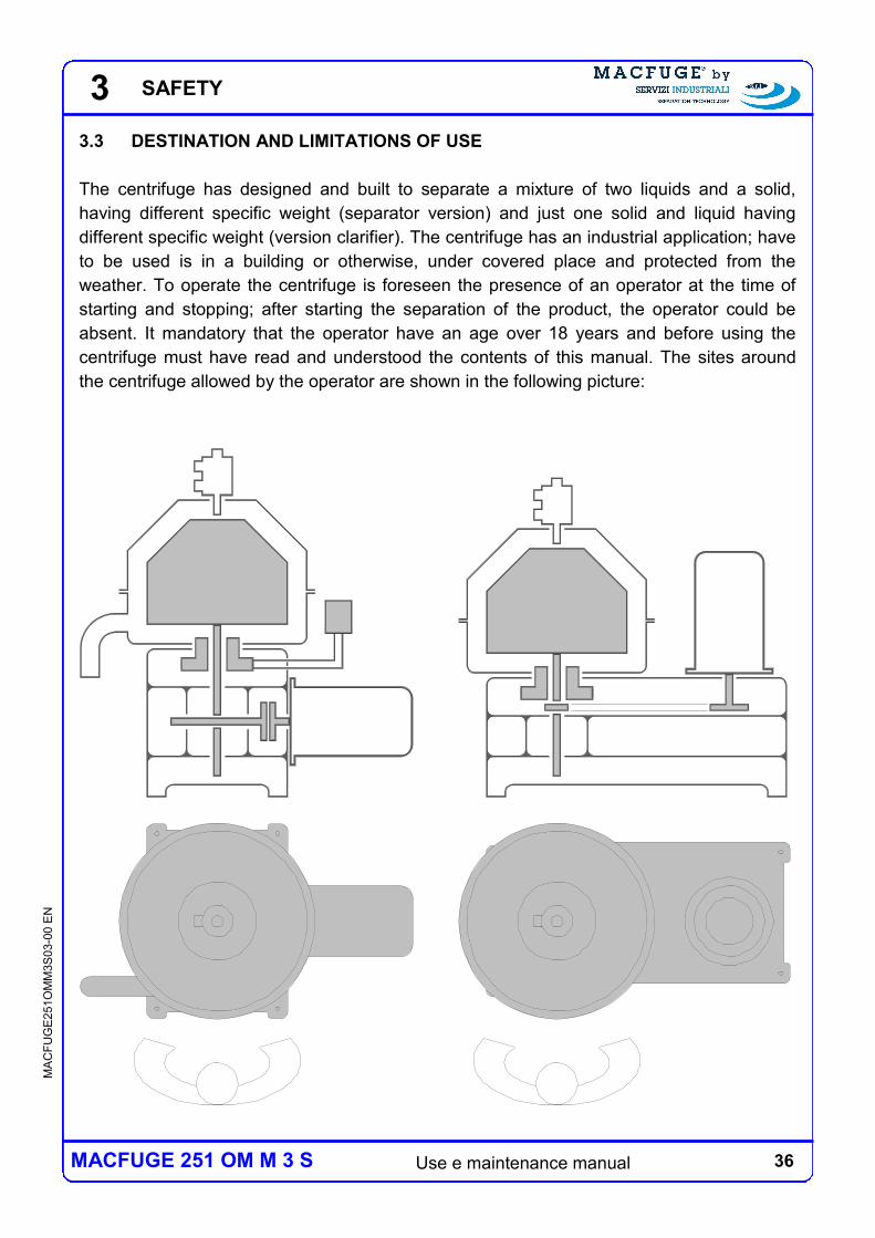
3.3 DESTINATION AND LIMITATIONS OF USE
The centrifuge has designed and built to separate a mixture of two liquids and a solid,
having different specific weight (separator version) and just one solid and liquid having
different specific weight (version clarifier). The centrifuge has an industrial application; have
to be used is in a building or otherwise, under covered place and protected from the
weather. To operate the centrifuge is foreseen the presence of an operator at the time of
starting and stopping; after starting the separation of the product, the operator could be
absent. It mandatory that the operator have an age over 18 years and before using the
centrifuge must have read and understood the contents of this manual. The sites around
the centrifuge allowed by the operator are shown in the following picture:
SAFETY
37 Use e maintenance manual
MA
CF
UG
E2
51O
MM
3S
03-0
0 E
N
MACFUGE 251 OM M 3 S
3
It is absolutely prohibited using the machine for other uses other than the one described, in
order to warrant in every moment the operator safety and the machine performances.
The operating limits are specified in the technical specification of the centrifuge (see
Chapter 8). Further restrictions may be introduced wiht respect of particular products or
applications, therefore we remind you to verify what is indicated in the contract of sale.
Respect the limits of use specified in this manual and those indicated in the
contract of sale, with particular attention to the limits on the rotation speed and
temperature, the density, the pressure discharge of the turbine and the flow
rate of the feeding product.
It 'absolutely forbidden to use the centrifuge in environments with a potentially
explosive atmosphere or the use in hazardous areas according to Directive
94/9/EC.
3.4 SOUND LEVEL AND VIBRATIONS
Just after having reached the standard working conditions, far from the start and stop
phases, the machine’s noise level, measured in an open environment with a phonometer
placed 1 meter away from the machine itself, far from echoic surfaces (measured in
according to the UNI EN ISO 3746 regulation) less than that indicated in the technical
specification of the centrifuge (see Chapter 8). During the start phase, in concomitance with
the structure’s resonance speeds, and during the solid phase discharge, the noise can
reach a higher level for short intervals of few seconds.
The centrifuge is delivered with an operating vibration level, lower than what indicated in the
technical specification of the centrifuge (see Chapter 8) (measure in mm / s rms), measured
at the significant points listed in the testing certificate (All.C of the present manual). A
measurement taken at different points leads to different values of the vibration level that are
however insignificant and therefore should not cause concerns. The vibration reaches
higher values during the start and stop phases in concomitance with the structure’s
resonance speeds, even though for a very limited time. The vibrations detection during
these temporary events is obviously insignificant.
CAUTION:
an erroneous bowl assembly or the accumulation of sediments in the sludge
chamber can cause a significant increase in the vibration level.
SAFETY
38 Use e maintenance manual
MA
CF
UG
E2
51O
MM
3S
03-0
0 E
N
MACFUGE 251 OM M 3 S
3
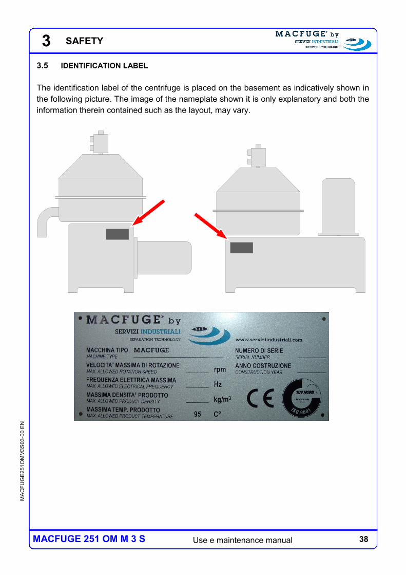
3.5 IDENTIFICATION LABEL
The identification label of the centrifuge is placed on the basement as indicatively shown in
the following picture. The image of the nameplate shown it is only explanatory and both the
information therein contained such as the layout, may vary.
SAFETY
39 Use e maintenance manual
MA
CF
UG
E2
51O
MM
3S
03-0
0 E
N
MACFUGE 251 OM M 3 S
4 HANDLING AND STORAGE
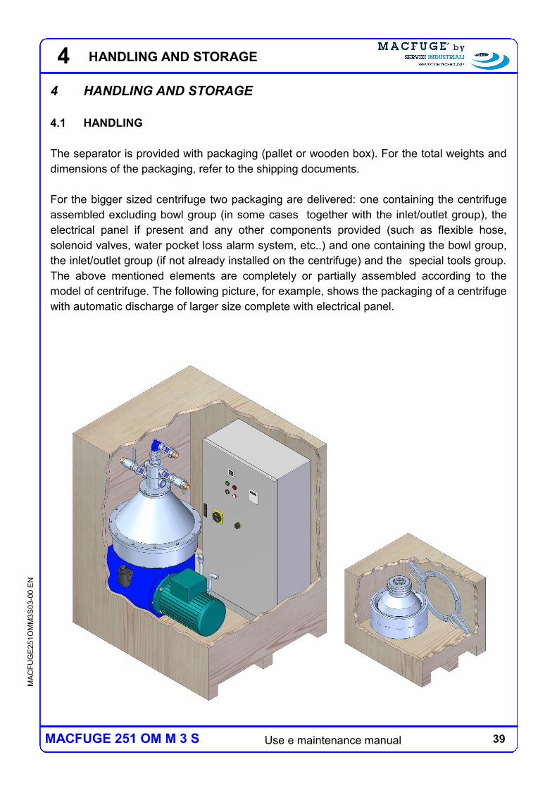
4.1 HANDLING
The separator is provided with packaging (pallet or wooden box). For the total weights and
dimensions of the packaging, refer to the shipping documents.
For the bigger sized centrifuge two packaging are delivered: one containing the centrifuge
assembled excluding bowl group (in some cases together with the inlet/outlet group), the
electrical panel if present and any other components provided (such as flexible hose,
solenoid valves, water pocket loss alarm system, etc..) and one containing the bowl group,
the inlet/outlet group (if not already installed on the centrifuge) and the special tools group.
The above mentioned elements are completely or partially assembled according to the
model of centrifuge. The following picture, for example, shows the packaging of a centrifuge
with automatic discharge of larger size complete with electrical panel.
4 HANDLING AND STORAGE
40 Use e maintenance manual
MA
CF
UG
E2
51O
MM
3S
03-0
0 E
N
MACFUGE 251 OM M 3 S
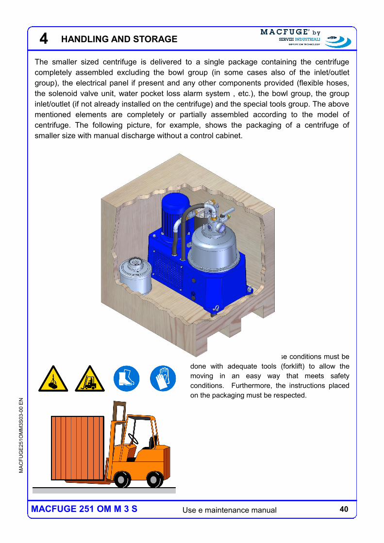
The smaller sized centrifuge is delivered to a single package containing the centrifuge
completely assembled excluding the bowl group (in some cases also of the inlet/outlet
group), the electrical panel if present and any other components provided (flexible hoses,
the solenoid valve unit, water pocket loss alarm system , etc.), the bowl group, the group
inlet/outlet (if not already installed on the centrifuge) and the special tools group. The above
mentioned elements are completely or partially assembled according to the model of
centrifuge. The following picture, for example, shows the packaging of a centrifuge of
smaller size with manual discharge without a control cabinet.
The handling/carriage in these conditions must be
done with adequate tools (forklift) to allow the
moving in an easy way that meets safety
conditions. Furthermore, the instructions placed
on the packaging must be respected.
4 HANDLING AND STORAGE
41 Use e maintenance manual
MA
CF
UG
E2
51O
MM
3S
03-0
0 E
N
MACFUGE 251 OM M 3 S
4
4
1
2
3
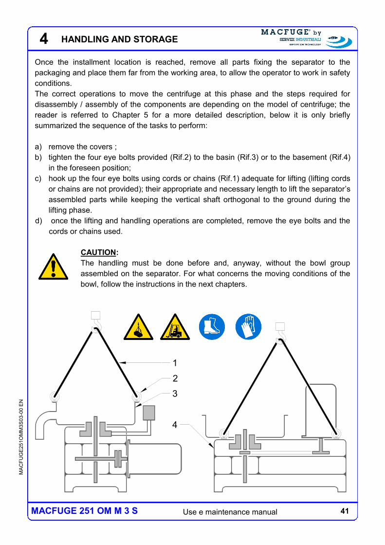
Once the installment location is reached, remove all parts fixing the separator to the
packaging and place them far from the working area, to allow the operator to work in safety
conditions.
The correct operations to move the centrifuge at this phase and the steps required for
disassembly / assembly of the components are depending on the model of centrifuge; the
reader is referred to Chapter 5 for a more detailed description, below it is only briefly
summarized the sequence of the tasks to perform:
a) remove the covers ;
b) tighten the four eye bolts provided (Rif.2) to the basin (Rif.3) or to the basement (Rif.4)
in the foreseen position;
c) hook up the four eye bolts using cords or chains (Rif.1) adequate for lifting (lifting cords
or chains are not provided); their appropriate and necessary length to lift the separator’s
assembled parts while keeping the vertical shaft orthogonal to the ground during the
lifting phase.
d) once the lifting and handling operations are completed, remove the eye bolts and the
cords or chains used.
CAUTION:
The handling must be done before and, anyway, without the bowl group
assembled on the separator. For what concerns the moving conditions of the
bowl, follow the instructions in the next chapters.
HANDLING AND STORAGE
42 Use e maintenance manual
MA
CF
UG
E2
51O
MM
3S
03-0
0 E
N
MACFUGE 251 OM M 3 S
4
4.2 STORAGE
If the machine is not immediately installed after delivery or not used for a long period of
time, it is necessary to comply with the following storage instructions.
The correct operations required for disassembly / assembly of the components are
depending on the model of centrifuge; the reader is referred to Chapter 10 for a more
detailed description, below it is only briefly summarized the sequence of the tasks to
perform:
if the separator has already been used, disassemble the product inlet/outlet groups,
disassemble the covers group and carefully wash all parts;
if the separator has already been used, completely disassemble the bowl group
and carefully wash all parts , Once that all parts are perfectly dry, the bowl can be
reassembled for ease of storage;
remove the lubricating oil from the carter;
disassemble the machine base group and the horizontal shaft group, the collar group
and the vertical shaft group, remove the residual lubricating oil and then grease all parts
that are wet by the lubricating oil during the process – with special care for the vertical
shaft, the horizontal shaft, the bearings, the internal parts of the collar (springs, little
pistons, etc.) and the surfaces touching other parts. a questo punto è ammesso, per
comodità di stoccaggio, rimontare le parti, gruppo coperture compreso; at this point the
parts - covers group included - can be reassembled for ease of storage (All.E);
make sure that the electrical panel is perfectly covered.
The centrifuge so treated and disassembled, must be placed in a dry
environment, protected from atmospheric agents.
Further instructions:
the bowl cannot be left on the vertical shaft when stored
at the first start, or after a long period of inactivity, lubricate the radial ball bearing, the
bearing that is supported by the bearing collar group, with the same oil used for the
transmission.
CAUTION:
not following the centrifuge’s storage instructions can cause damages to the
centrifuge.
HANDLING AND STORAGE
43 Use e maintenance manual
MA
CF
UG
E2
51O
MM
3S
03-0
0 E
N
MACFUGE 251 OM M 3 S
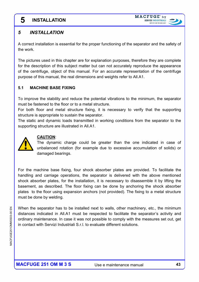
5 INSTALLATION
A correct installation is essential for the proper functioning of the separator and the safety of
the work.
The pictures used in this chapter are for explanation purposes, therefore they are complete
for the description of this subject matter but can not accurately reproduce the appearance
of the centrifuge, object of this manual. For an accurate representation of the centrifuge
purpose of this manual, the real dimensions and weights refer to All.A1.
5.1 MACHINE BASE FIXING
To improve the stability and reduce the potential vibrations to the minimum, the separator
must be fastened to the floor or to a metal structure.
For both floor and metal structure fixing, it is necessary to verify that the supporting
structure is appropriate to sustain the separator.
The static and dynamic loads transmitted in working conditions from the separator to the
supporting structure are illustrated in All.A1.
CAUTION:
The dynamic charge could be greater than the one indicated in case of
unbalanced rotation (for example due to excessive accumulation of solids) or
damaged bearings.
For the machine base fixing, four shock absorber plates are provided. To facilitate the
handling and carriage operations, the separator is delivered with the above mentioned
shock absorber plates, for the installation, it is necessary to disassemble it by lifting the
basement, as described. The floor fixing can be done by anchoring the shock absorber
plates to the floor using expansion anchors (not provided). The fixing to a metal structure
must be done by welding.
When the separator has to be installed next to walls, other machinery, etc., the minimum
distances indicated in All.A1 must be respected to facilitate the separator’s activity and
ordinary maintenance. In case it was not possible to comply with the measures set out, get
in contact with Servizi Industriali S.r.l. to evaluate different solutions.
5 INSTALLATION
44 Use e maintenance manual
MA
CF
UG
E2
51O
MM
3S
03-0
0 E
N
MACFUGE 251 OM M 3 S
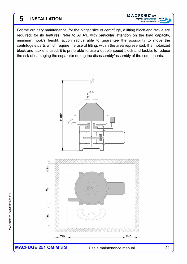
For the ordinary maintenance, for the bigger size of centrifuge, a lifting block and tackle are
required; for its features, refer to All.A1, with particular attention on the load capacity,
minimum hook’s height, action radius able to guarantee the possibility to move the
centrifuge’s parts which require the use of lifting, within the area represented. If a motorized
block and tackle is used, it is preferable to use a double speed block and tackle, to reduce
the risk of damaging the separator during the disassembly/assembly of the components.
min
.W
min
.
min. L min.
H m
in.
5 INSTALLATION
45 Use e maintenance manual
MA
CF
UG
E2
51O
MM
3S
03-0
0 E
N
MACFUGE 251 OM M 3 S
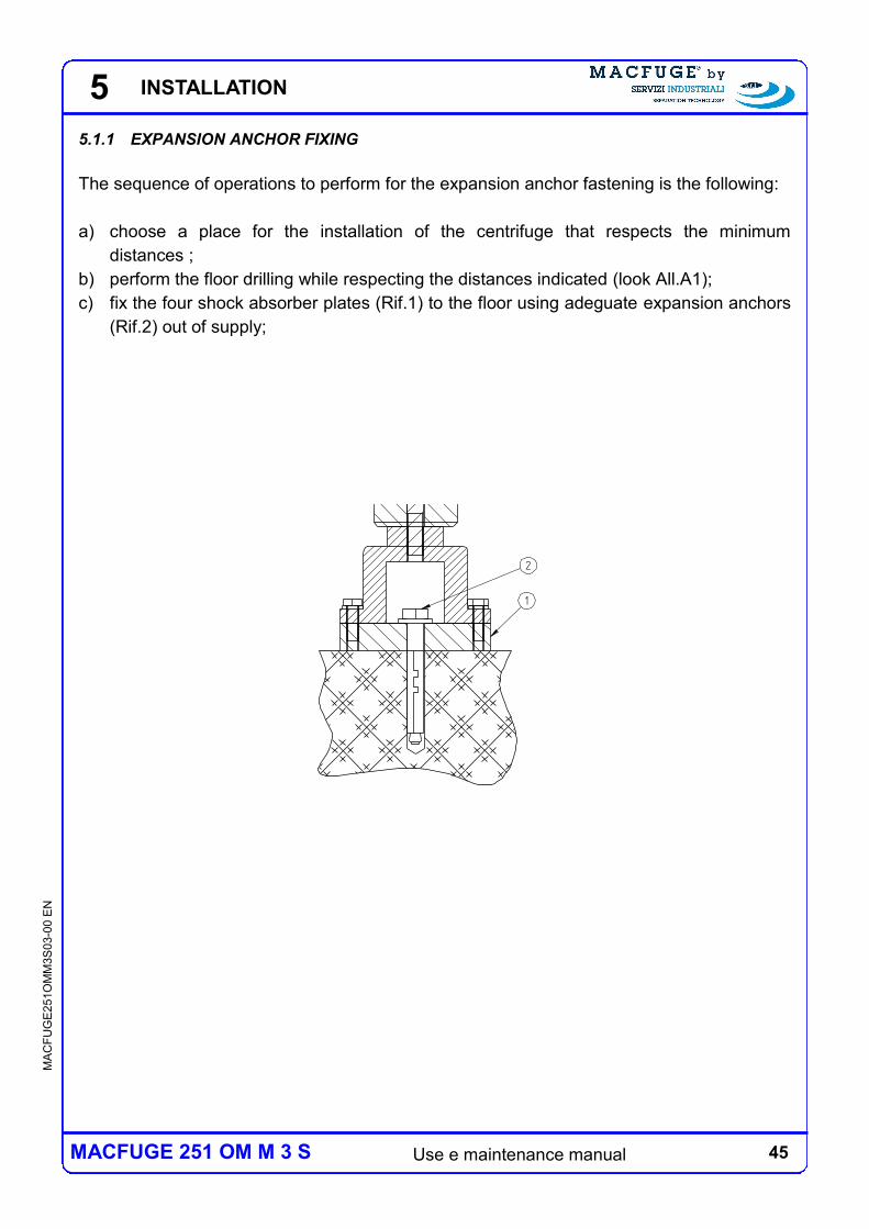
5.1.1 EXPANSION ANCHOR FIXING
The sequence of operations to perform for the expansion anchor fastening is the following:
a) choose a place for the installation of the centrifuge that respects the minimum
distances ;
b) perform the floor drilling while respecting the distances indicated (look All.A1);
c) fix the four shock absorber plates (Rif.1) to the floor using adeguate expansion anchors
(Rif.2) out of supply;
SEZIONE A-A
2
1
5 INSTALLATION
46 Use e maintenance manual
MA
CF
UG
E2
51O
MM
3S
03-0
0 E
N
MACFUGE 251 OM M 3 S
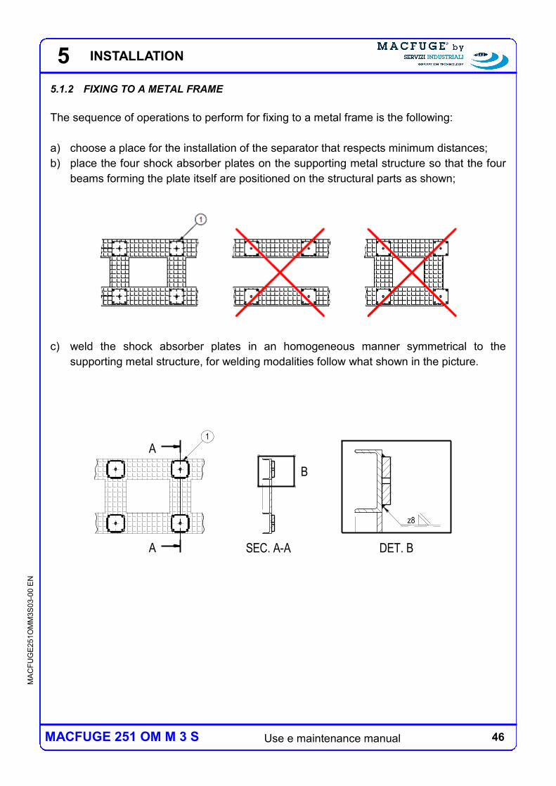
5.1.2 FIXING TO A METAL FRAME
The sequence of operations to perform for fixing to a metal frame is the following:
a) choose a place for the installation of the separator that respects minimum distances;
b) place the four shock absorber plates on the supporting metal structure so that the four
beams forming the plate itself are positioned on the structural parts as shown;
c) weld the shock absorber plates in an homogeneous manner symmetrical to the
supporting metal structure, for welding modalities follow what shown in the picture.
1
A
A SEC. A-A
B
DET. B
z8
5 INSTALLATION
47 Use e maintenance manual
MA
CF
UG
E2
51O
MM
3S
03-0
0 E
N
MACFUGE 251 OM M 3 S
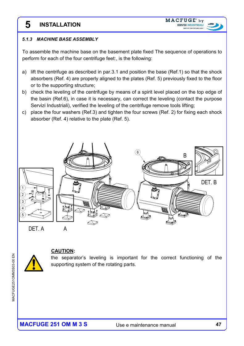
5.1.3 MACHINE BASE ASSEMBLY
To assemble the machine base on the basement plate fixed The sequence of operations to
perform for each of the four centrifuge feet:, is the following:
a) lift the centrifuge as described in par.3.1 and position the base (Ref.1) so that the shock
absorbers (Ref. 4) are properly aligned to the plates (Ref. 5) previously fixed to the floor
or to the supporting structure;
b) check the leveling of the centrifuge by means of a spirit level placed on the top edge of
the basin (Ref.6), in case it is necessary, can correct the leveling (contact the purpose
Servizi Industriali), verified the leveling of the centrifuge remove tools lifting;
c) place the four washers (Ref.3) and tighten the four screws (Ref. 2) for fixing each shock
absorber (Ref. 4) relative to the plate (Ref. 5).
CAUTION:
the separator’s leveling is important for the correct functioning of the
supporting system of the rotating parts.
ADET. A
1
2
3
5
4
6B
DET. B
5 INSTALLATION
48 Use e maintenance manual
MA
CF
UG
E2
51O
MM
3S
03-0
0 E
N
MACFUGE 251 OM M 3 S
5.2 CENTRIFUGE ASSEMBLY
Once fixed on the basement, it is possible proceed to the assembly of the centrifuge. The
operations to follow to assemble the centrifuge are depending on the model, the reader is
referred to Chapter 10 for a detailed description; below it is only briefly summarized the
sequence of operations to be performed: the bowl assembly, installation of covers and
outlets group assembling.
5.2.1 LUBRICATION
The transmission mechanisms (bearing and gear if the centrifuge have this type of moving
gear) are lubricated, if foreseen, by oil splashing. The centrifuge is delivered with the
appropriate oil load, therefore no topping up is required. Before any start it is however
necessary to verify the oil level in the carter, as described in (vedi Cap.10). At the first start,
or after a long period of inactivity, lubricate the radial ball bearing, that is, the ball bearing
supported by the collar group, using the same oil used for the transmission.
5 INSTALLATION
49 Use e maintenance manual
MA
CF
UG
E2
51O
MM
3S
03-0
0 E
N
MACFUGE 251 OM M 3 S
6 CONNECTIONS
6 CONNECTIONS
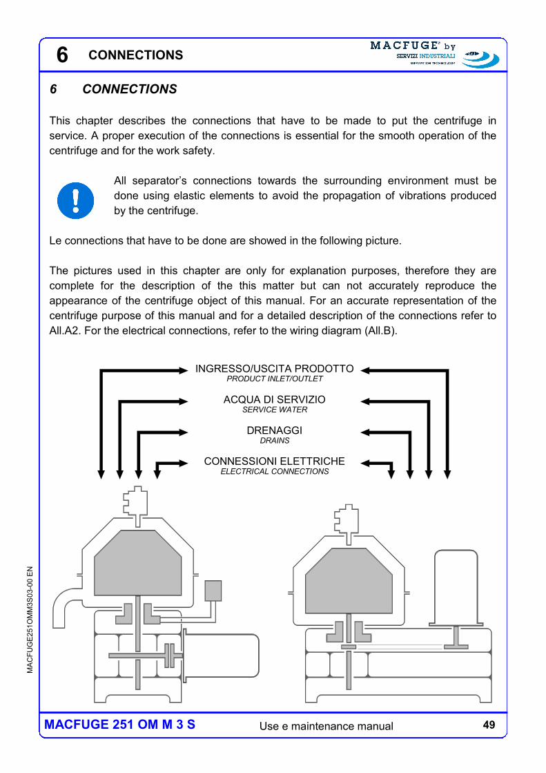
This chapter describes the connections that have to be made to put the centrifuge in
service. A proper execution of the connections is essential for the smooth operation of the
centrifuge and for the work safety.
All separator’s connections towards the surrounding environment must be
done using elastic elements to avoid the propagation of vibrations produced
by the centrifuge.
Le connections that have to be done are showed in the following picture.
The pictures used in this chapter are only for explanation purposes, therefore they are
complete for the description of the this matter but can not accurately reproduce the
appearance of the centrifuge object of this manual. For an accurate representation of the
centrifuge purpose of this manual and for a detailed description of the connections refer to
All.A2. For the electrical connections, refer to the wiring diagram (All.B).
INGRESSO/USCITA PRODOTTOPRODUCT INLET/OUTLET
ACQUA DI SERVIZIOSERVICE WATER
DRENAGGIDRAINS
CONNESSIONI ELETTRICHEELECTRICAL CONNECTIONS
50 Use e maintenance manual
MA
CF
UG
E2
51O
MM
3S
03-0
0 E
N
MACFUGE 251 OM M 3 S
6
A
B
C
D
A
B
C
D
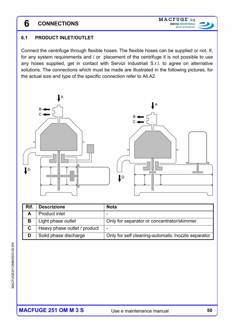
6.1 PRODUCT INLET/OUTLET
Connect the centrifuge through flexible hoses. The flexible hoses can be supplied or not. If,
for any system requirements and / or placement of the centrifuge it is not possible to use
any hoses supplied, get in contact with Servizi Industriali S.r.l. to agree on alternative
solutions. The connections which must be made are illustrated in the following pictures, for
the actual size and type of the specific connection refer to All.A2.
Rif. Nota Descrizione
A - Product inlet
B Only for separator or concentrator/skimmer Light phase outlet
C - Heavy phase outlet / product
D Only for self cleaning-automatic /nozzle separator Solid phase discharge
CONNECTIONS
51 Use e maintenance manual
MA
CF
UG
E2
51O
MM
3S
03-0
0 E
N
MACFUGE 251 OM M 3 S
6.1.1 PRODUCT INLET
The supply of the product to the separator requires a pressure head essentially due to the
charge losses caused by the percolation of the product through the supply pipe. This
pressure head depends on the supply flow rate and on the physical features of the product,
indicative values are reported into the specific technical data sheet of the centrifuge
(refer to Cap.7).
6.1.2 LIGHT AND HEAVY PHASE OUTLETS
Both light and heavy phase, or the only liquid phase when the centrifuge is a clarifier, can
be extracted by turbine or by gravity. The configuration of the centrifuge object of this
manual, is described in the technical specification of the centrifuge (refer to section 7). The
maximum prevalence output from the turbines, depends on both flow rate and physical
characteristics of the product; indicative values are reported into the specific technical data
sheet of the centrifuge (refer to section 7). On the outlet line can be installed a regulating
valve that allows to vary the operating pressure of the turbine and thus the position of the
separation line between the two phases inside the centrifuge, or adjusts the separation
efficiency (refer to Section 6). The outlet current pressure of the turbine is read on the
manometer.
CAUTION:
The pressure required by the turbine must always allow the extraction of all
the product to avoid overflowing and surpassing in any case the limit reported
on the specific technical sheet, a possible overflow and a consequent contact
between the rotating bowl and the liquid extracted could damage to the
centrifuge and create potentially dangerous to people and things.
CAUTION:
in the case of outlet by gravity make the connection so that it is in any case
guaranteed the outflow of the liquid phase, in order to avoid overflow from the
collecting space, a possible overflow and a consequent contact between the
rotating bowl and the liquid extracted could damage to the centrifuge and
create potentially dangerous to people and things.
Note: In some centrifuge models, although it is installed a turbine, the product must be
drained by gravity and it is not allowed take pressure to turbine.
6 CONNECTIONS
52 Use e maintenance manual
MA
CF
UG
E2
51O
MM
3S
03-0
0 E
N
MACFUGE 251 OM M 3 S
6.1.3 SOLID PHASE OUTLET
In the case of manual cleaning (solid bowl) centrifuge the solid phase is accrued inside the
bowl and it is necessary to stop the centrifuge and partially disassemble it to remove it. In
the case of self cleaning centrifuge (automatic discharge ) the solid phase is automatically
expelled from the bowl in a discontinuous way, at time intervals set through the control
panel. In the case of nozzles centrifuge the solid phase is automatically expelled from the
bowl in a continuous way through the nozzles. Both for the centrifuge with automatic
discharge and with nozzles discharge, the solid discharged it is collected in the basin, and
finally conveyed to the exhaust pipe from which, in the case of self cleaning centrifuge it is
ejected through high speed. For the solid phase may be foreseen a sludge tank. In the case
it is not supply by Servizi Industriali S.r.l. must be properly sized and meet the following
requirements:
must be provided with a safety drainage system placed at a lower level than the
machine’s outlet to guarantee that an unexpected discharge accumulation reaches the
rotating parts inside the centrifuge;
if it is a covered tank must have a total volume increased by 100% compared to the
volume of solid discharged expected before emptying of the tank;
if it is a covered tank, it must be open towards the outside through a vent with at least
100 cm2 surface of useful passage, built and positioned to avoid the leaking of material
during the discharge;
the connection between the machine and the collecting chamber must be done using
flexible elements to avoid the diffusion of the vibrations produced by the separator.
CAUTION:
The solid phase outlet must be channeled to always guarantee the emptying
of the basin since an accidental accumulation of discharged material inside
the basin and a consequent contact between the rotating bowl and the
discharged material could cause damages to the separator and create
situation potentially dangerous for people and things
CAUTELA:
The solid phase outlet must always be channeled in a way that guarantees
that the outlet itself it is always free and at atmospheric pressure
6 CONNECTIONS
53 Use e maintenance manual
MA
CF
UG
E2
51O
MM
3S
03-0
0 E
N
MACFUGE 251 OM M 3 S
BA
C
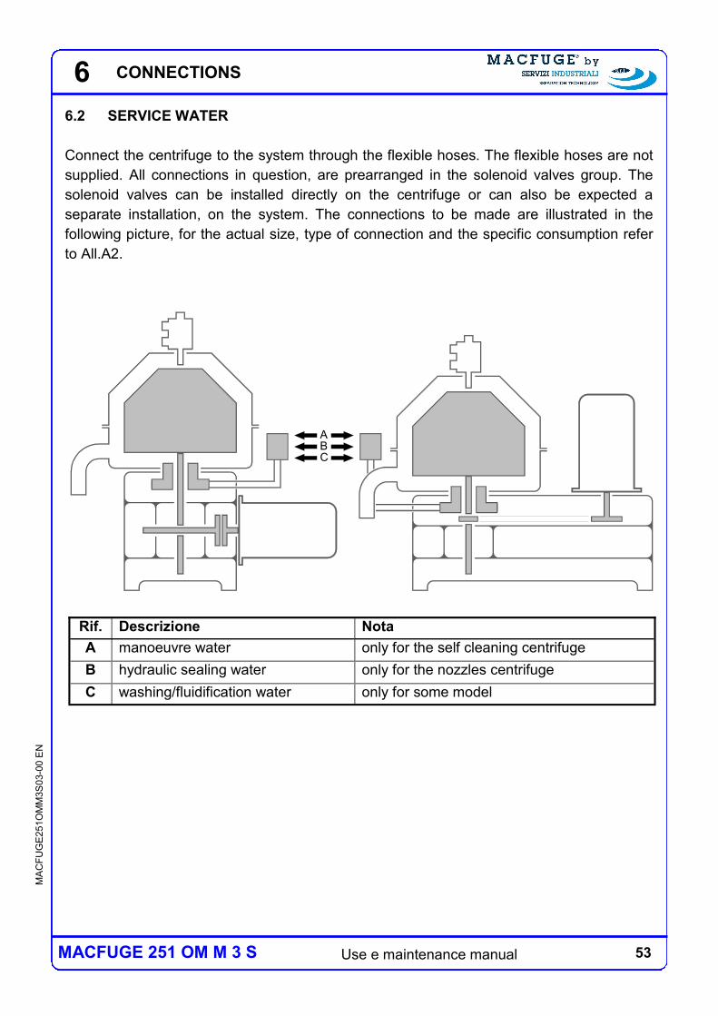
6.2 SERVICE WATER
Connect the centrifuge to the system through the flexible hoses. The flexible hoses are not
supplied. All connections in question, are prearranged in the solenoid valves group. The
solenoid valves can be installed directly on the centrifuge or can also be expected a
separate installation, on the system. The connections to be made are illustrated in the
following picture, for the actual size, type of connection and the specific consumption refer
to All.A2.
Rif. Descrizione Nota
A manoeuvre water only for the self cleaning centrifuge
B hydraulic sealing water only for the nozzles centrifuge
C washing/fluidification water only for some model
6 CONNECTIONS
54 Use e maintenance manual
MA
CF
UG
E2
51O
MM
3S
03-0
0 E
N
MACFUGE 251 OM M 3 S
6.2.1 MANOEUVRE WATER
The water driven to this inlet is used through two distinct solenoid valves (opening and
closing lines), for the operations relative to the discharge of the solid phase.
Must be met the following requirements:
the water must be clean, in particular, it must not contain solid particles in suspension;
must have a hardness of less than 22 ° f in order to reduce at minimum the limescale
deposits that may interfere with the automatic discharge system;
must be provided with a pressure of 2.5 to 5 barg;
must be provided with a temperature of 5÷30 °C;
must be provided through a line that can guaranty a flow rate of at least 3000 l / h;
must not be demineralized.
At the inlet of the line there is a pressure reducer that must be calibrated at 1÷1,5 barg. The
consumption depends on the frequency and the type of discharge (partial or total) made,
approximately the consumption is equal to 1 l per discharge (refer to All.A2).
On the opening and closing lines are prearranged two by-pass, or alternatively the solenoid
valves are equipped with manual actuator, to perform manually maneuvers during the stat
up phase, optimization of the setting or for troubleshooting. The water used for maneuvers
functions is conveyed to the relative
drainage from which exits by gravity.
6.2.2 HYDRAULIC SEALING WATER
The water channeled to this inlet is used to create an hydraulic sealing (conventionally
called “pocket”) inside the bowl or to recreate it after a total discharge. In the case of
manual cleaning centrifuge (solid bowl) the hydraulic seal water introduction must be done
manually once before the product feeding. In the case of self cleaning centrifuge (automatic
discharge) the hydraulic seal water introduction occurs automatically through a dedicated
solenoid valve (installed in the solenoid valves group) after each discharge if necessary.
In the case of self cleaning centrifuge (automatic discharge) must be met the following
requirements:
must be supplied with a pressure equal to 2,5÷5 barg;
must have a temperature that does not depart more than 10°C from that of the
processed product in order to avoid the development of emulsions that can damage the
efficiency of the separation due to thermal shocks at the entry of the bowl;
must be provided through a line that can guaranty a flow rate of at least 3000 l/h.
6 CONNECTIONS
55 Use e maintenance manual
MA
CF
UG
E2
51O
MM
3S
03-0
0 E
N
MACFUGE 251 OM M 3 S
At the inlet of the line there is a pressure reducer that must be calibrated at 1,5÷2,5 barg.
The consumption depends on the frequency and the type of discharge (partial or total) as
well as the capacity of the sludge chamber. The consuption can be null, in the case where
the percentage of heavy phase in the product is such as to make unnecessary to supply
additional water, or can reach the maximum, in the case in which are carried out frequent
discharges, which can be calculated according to the following formula:
On line is prearranged one by-pass, or alternatively the solenoid valve is equipped with
manual actuator, to perform manually the hydraulic seal water introduction during the stat
up phase, optimization of the setting or for troubleshooting. Products where the heavy
phase is not water, pocket should be created with the same heavy phase cleaned
6.2.3 WASHING/FLUIDIFICATION WATER
The water channeled to this inlet is used through two distinct solenoid valves (washing and
fluidification lines), for the following operations:
for the cleaning of the discharge volute of the basin (washing line);
for the cleaning of the external surface of the bowl and the internal surface of the cover,
(washing line)
fluidification of the heavy phase inside the bowl (fluidification line)
for the cleaning of the sight glass (fluidification line).
Must be met the following requirements:
the water must be clean, in particular t must not contain solid particles in suspension;
must be provided with a pressure of 1,5÷5 barg;
must be provided with a temperature slightly lower than that of the product, in order to
perform a cooling effect
None of the functions above described it is strictly necessary, the opportunity of the use
depends on both the nature of the product and the operating conditions. The consumption
can be null, when it is not necessary to perform any of the described operations, or can
reach the approximate maximum of 150 l/h. On the differents lines are prearranged manual
taps in order to exclude the unnecessary lines or partialize the respective flow rate.
The washing line water, flows to the discharge of the solids, the fluidification line water,
flows to the heavy phase outlet.
consumo acqua di sacca (l/h) = 1,5 * volume camera fanghi (l) * frequenza scarichi (1/h)
6 CONNECTIONS
56 Use e maintenance manual
MA
CF
UG
E2
51O
MM
3S
03-0
0 E
N
MACFUGE 251 OM M 3 S
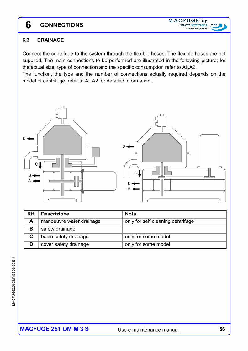
Rif. Descrizione Nota
A manoeuvre water drainage only for self cleaning centrifuge
B safety drainage
C basin safety drainage only for some model
D cover safety drainage only for some model
B
A
C
D
B
A
C
D
6.3 DRAINAGE
Connect the centrifuge to the system through the flexible hoses. The flexible hoses are not
supplied. The main connections to be performed are illustrated in the following picture; for
the actual size, type of connection and the specific consumption refer to All.A2.
The function, the type and the number of connections actually required depends on the
model of centrifuge, refer to All.A2 for detailed information.
6 CONNECTIONS
57 Use e maintenance manual
MA
CF
UG
E2
51O
MM
3S
03-0
0 E
N
MACFUGE 251 OM M 3 S
6
6.3.1 MANOEUVRING WATER DRAINAGE
The water used to perform the automatic diascharge maneuvers drain out by gravity from
the drainage of the maneuvering water. In some models of centrifuge it is planned to install
a siphon on the outlet line (refer to All.A2). In some models of centrifuge the drainage of
maneuvering water and the safety drainage are together.
CAUTION:
The maneuvering water drainage must be channeled to a line in order to
guarantee the emptying of the basin since an accidental accumulation of
water inside the basin and a consequent contact between the rotating bowl
and the water could cause damages to the separator and create situation
potentially dangerous for people and things
6.3.2 SAFETY DRAINAGE
I drenaggi di sicurezza servono a consentire il deflusso di acqua di servizio e del prodotto in
caso di tracimazioni dovute a malfunzionamenti o errate manovre, allo scopo di garantire la
sicurezza ed evitare danni di maggiore entità alla centrifuga anche nelle suddette
evenienze. In particolare servono ad evitare che l’acqua di servizio e il prodotto
eventualmente tracimati vengano contatto con le parti rotanti o possano raggiungere il
carter contente l’olio di lubrificazione. Per i motivi di cui sopra, in condizioni di lavoro
regolari, dai drenaggi di sicurezza non deve uscire ne acqua ne prodotto, eventualmente
solo condensa. I drenaggi di sicurezza relativi al catino e alla copertura sono presenti solo
su alcuni modelli di centrifuga.
CAUTION:
The safety drainage must be channeled to a lines in order to guarantee the
emptying of the basin since an accidental accumulation of water or product
inside the basin and a consequent contact between the rotating bowl and the
water or product could cause damages to the separator and create situation
potentially dangerous for people and things.
CAUTION:
The safety drainage must be channeled to an open lines in order to guarantee
air circulation and emptying of the basin.
Drains should not be put together of merged into common lines without the
consent of Servizi Industriali S.r.l.
CONNECTIONS
58 Use e maintenance manual
MA
CF
UG
E2
51O
MM
3S
03-0
0 E
N
MACFUGE 251 OM M 3 S
6
6.4 ELECTRIC CONNECTIONS
This paragraph describes the tasks that must be performed to install the electrical panel
and how to realize the related electrical connections.
6.4.1 INSTALLATION OF THE ELECTRICAL PANEL
The electric panel features (set up, dimensions and appearance) can vary according to the
functionality required. This paragraph describes the general modalities for a correct
carriage and installation.
For the actual features of the electrical panel, its correct installation and
correct execution of the electrical connections refer to the instructions in the
electric scheme attached to this guide (All.B).
The electrical panel is delivered packed together with the centrifuge, its dimensions are
described in All.B. Once the installation location is reached, remove all parts fixing the
panel to the package. The carriage of the electrical panel must be done using proper
equipment (forklift), to facilitate carriage while respecting safety conditions. In the case of
cabinets to be placed on the ground, to lift the electrical panel using a forklift, it is necessary
to remove the front and the rear part of the cabinet’s baseboard.
Place the panel close to the separator. In order to allow the regular air inflowing and out
flowing, a distance of at least 20 cm must be allowed between the lateral walls of the panel,
where the air intakes for cooling are located, and any other obstacle.
The panel cannot be installed at a distance greater than 100 m from the
centrifuge. In case this is necessary, due to the specific conditions of the plant
and/or to the machine positioning, contact Servizi Industriali S.r.l.
If the specific conditions of the plant and/or to the machine positioning do not
allow the installation of the electrical panel in the immediate proximity of the
centrifuge, a button for emergency stop must be installed close to the
separator. For this matter, contact Servizi IndustrialiS.r.l.
CONNECTIONS
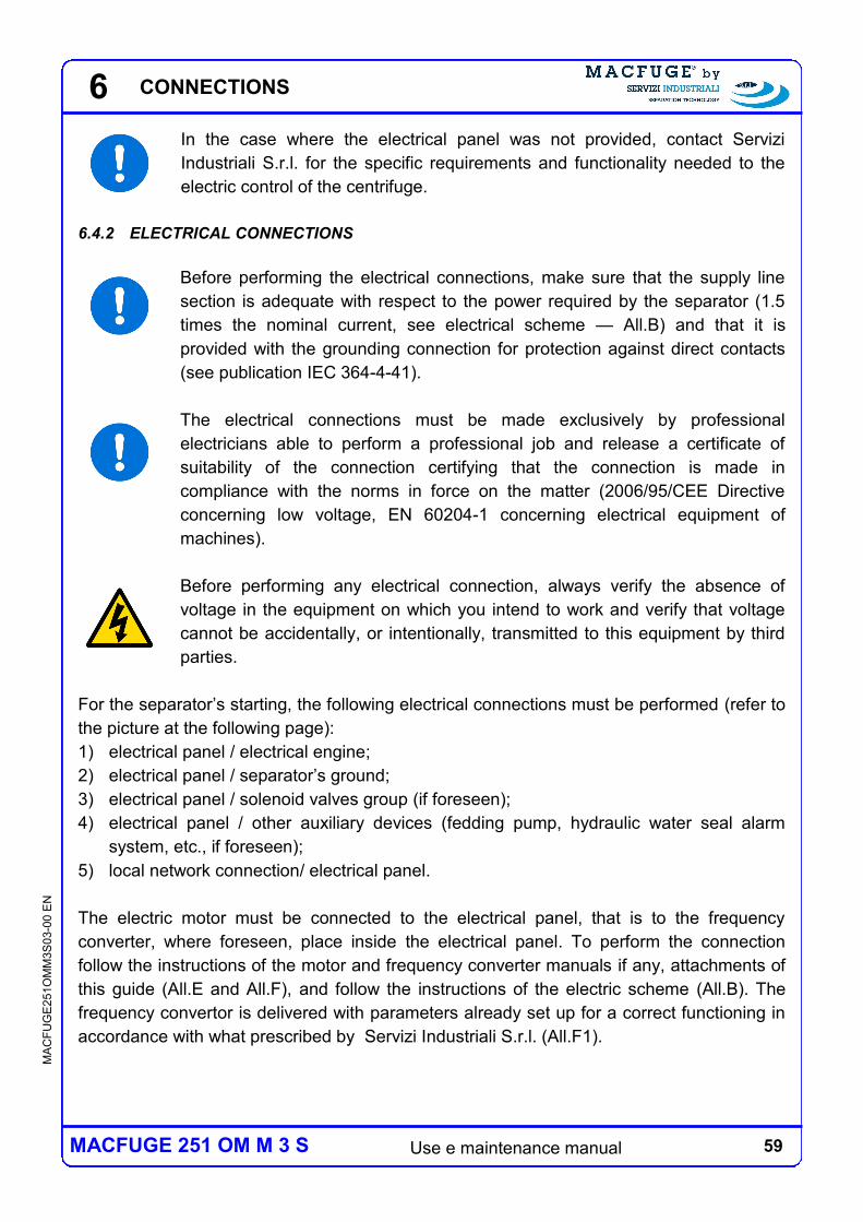
59 Use e maintenance manual
MA
CF
UG
E2
51O
MM
3S
03-0
0 E
N
MACFUGE 251 OM M 3 S
6
In the case where the electrical panel was not provided, contact Servizi
Industriali S.r.l. for the specific requirements and functionality needed to the
electric control of the centrifuge.
6.4.2 ELECTRICAL CONNECTIONS
Before performing the electrical connections, make sure that the supply line
section is adequate with respect to the power required by the separator (1.5
times the nominal current, see electrical scheme — All.B) and that it is
provided with the grounding connection for protection against direct contacts
(see publication IEC 364-4-41).
The electrical connections must be made exclusively by professional
electricians able to perform a professional job and release a certificate of
suitability of the connection certifying that the connection is made in
compliance with the norms in force on the matter (2006/95/CEE Directive
concerning low voltage, EN 60204-1 concerning electrical equipment of
machines).
Before performing any electrical connection, always verify the absence of
voltage in the equipment on which you intend to work and verify that voltage
cannot be accidentally, or intentionally, transmitted to this equipment by third
parties.
For the separator’s starting, the following electrical connections must be performed (refer to
the picture at the following page):
1) electrical panel / electrical engine;
2) electrical panel / separator’s ground;
3) electrical panel / solenoid valves group (if foreseen);
4) electrical panel / other auxiliary devices (fedding pump, hydraulic water seal alarm
system, etc., if foreseen);
5) local network connection/ electrical panel.
The electric motor must be connected to the electrical panel, that is to the frequency
converter, where foreseen, place inside the electrical panel. To perform the connection
follow the instructions of the motor and frequency converter manuals if any, attachments of
this guide (All.E and All.F), and follow the instructions of the electric scheme (All.B). The
frequency convertor is delivered with parameters already set up for a correct functioning in
accordance with what prescribed by Servizi Industriali S.r.l. (All.F1).
CONNECTIONS
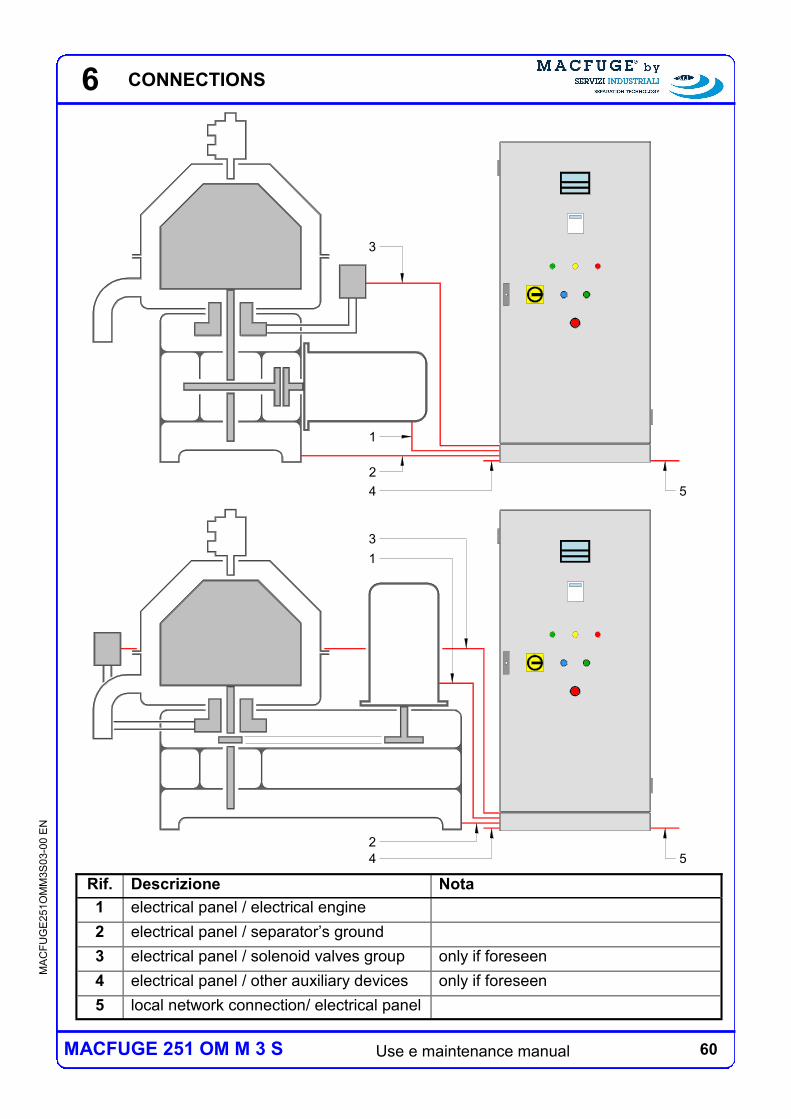
60 Use e maintenance manual
MA
CF
UG
E2
51O
MM
3S
03-0
0 E
N
MACFUGE 251 OM M 3 S
6
Rif. Descrizione Nota
1 electrical panel / electrical engine
2 electrical panel / separator’s ground
3 electrical panel / solenoid valves group only if foreseen
4 electrical panel / other auxiliary devices only if foreseen
5 local network connection/ electrical panel
1
2
4 5
54
2
3
3
1
CONNECTIONS
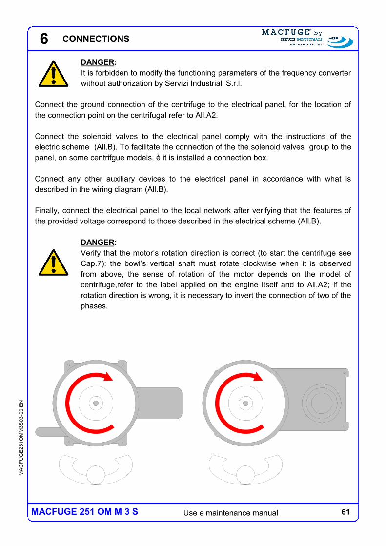
61 Use e maintenance manual
MA
CF
UG
E2
51O
MM
3S
03-0
0 E
N
MACFUGE 251 OM M 3 S
6
DANGER:
It is forbidden to modify the functioning parameters of the frequency converter
without authorization by Servizi Industriali S.r.l.
Connect the ground connection of the centrifuge to the electrical panel, for the location of
the connection point on the centrifugal refer to All.A2.
Connect the solenoid valves to the electrical panel comply with the instructions of the
electric scheme (All.B). To facilitate the connection of the the solenoid valves group to the
panel, on some centrifgue models, è it is installed a connection box.
Connect any other auxiliary devices to the electrical panel in accordance with what is
described in the wiring diagram (All.B).
Finally, connect the electrical panel to the local network after verifying that the features of
the provided voltage correspond to those described in the electrical scheme (All.B).
DANGER:
Verify that the motor’s rotation direction is correct (to start the centrifuge see
Cap.7): the bowl’s vertical shaft must rotate clockwise when it is observed
from above, the sense of rotation of the motor depends on the model of
centrifuge,refer to the label applied on the engine itself and to All.A2; if the
rotation direction is wrong, it is necessary to invert the connection of two of the
phases.
CONNECTIONS
62 Use e maintenance manual
MA
CF
UG
E2
51O
MM
3S
03-0
0 E
N
MACFUGE 251 OM M 3 S
6 CONNECTIONS
63 Use e maintenance manual
MA
CF
UG
E2
51O
MM
3S
03-0
0 E
N
MACFUGE 251 OM M 3 S
7
7 USAGE AND FUNCTIONING
The centrifuge described in this manual is a self cleaning separator with manual discharge,
the heavy and light phases are extracted by means of turbines, the transmission is with
mechanical gears. The centrifuge is supplied complete of all necessary devices for the use
as clarifier configuration; in this case the only purified liquid phase is extracted by means of
the turbine at the light phase outlet. The destination and limits of use of the centrifuge (refer
to Ch.3) are specified in the data sheet of the centrifuge (refer to Chapter 8) and in the
sales contract.
Comply wiht the limits of use specified in this manual and those indicated in
the contract of sale, with particular attention to the limits on the rotation speed,
temperature, the density, the discharge pressure of the turbine and the
product flow rate at the centrifuge's feeding.
USAGE AND FUNCTIONING
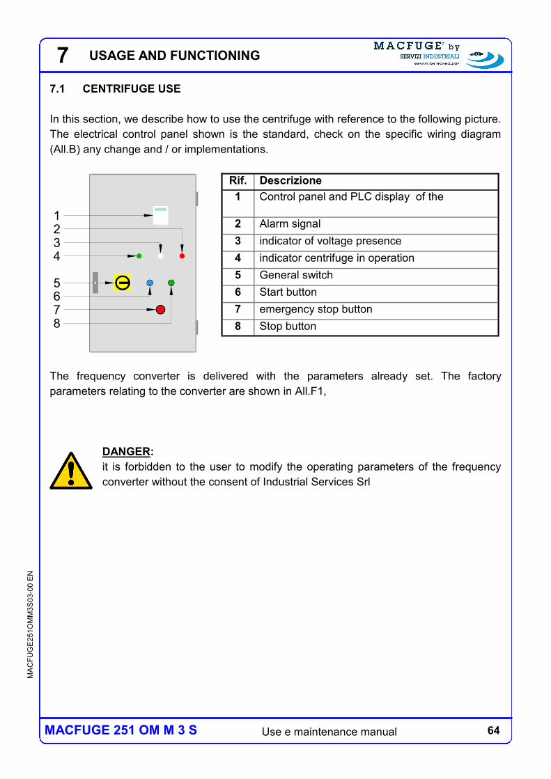
64 Use e maintenance manual
MA
CF
UG
E2
51O
MM
3S
03-0
0 E
N
MACFUGE 251 OM M 3 S
7.1 CENTRIFUGE USE
In this section, we describe how to use the centrifuge with reference to the following picture.
The electrical control panel shown is the standard, check on the specific wiring diagram
(All.B) any change and / or implementations.
The frequency converter is delivered with the parameters already set. The factory
parameters relating to the converter are shown in All.F1,
DANGER:
it is forbidden to the user to modify the operating parameters of the frequency
converter without the consent of Industrial Services Srl
7 USAGE AND FUNCTIONING
Rif. Descrizione
1 Control panel and PLC display of the
2 Alarm signal
3 indicator of voltage presence
4 indicator centrifuge in operation
5 General switch
6 Start button
7 emergency stop button
8 Stop button
1
8
6
32
4
7
5
65 Use e maintenance manual
MA
CF
UG
E2
51O
MM
3S
03-0
0 E
N
MACFUGE 251 OM M 3 S
7.2 STARTING
DANGER:
before starting the centrifuge verify that:
the bowl is mounted correctly, in particular that locking nut is screwed on
correctly (see Chapter 10);
The covers are mounted correctly (see Chapter 10);
The centrifuge is mounted correctly (see Chapter 10);
The electrical connections are made correctly (see Chapter 6);
The bowl is full of water (see Chapter 6);
do not let the centrifuge rotation in vacuum for more than half an hour.
CAUTION:
before starting the centrifuge verify that:
the connecting pipes are fitted correctly;
check that the position of the regulating valves and any shut-off valves is
that destre
Also verify that the necessary utilities (see Section 6) are available.
Once you have checked all of the above you can start the centrifuge:
a) Fill the bowl completely (see Chap.6);
b) supply voltage to the control panel to the main switch: the presence of white light
voltage turns on, the frequency converter is in tension.
c) Press the start button: the motor is powered and controlled by the frequency
converter, the green light on the control panel lights up. The starting time is a parameter
setting of the frequency converter (see All.F1).
d) check the direction of rotation of the motor (see Chap.6): interrupt the starter in
the case where the direction of rotation were to be wrong
e) supervise the centrifuge during the starting phase: interrupt the starter in case of
malfunctions (high vibrations, unusual noise, etc..);
f) feed centrifuge with the product: see note.
g) verify the operating conditions of the centrifuge: in particular the electric
absorption and the discharge pressure of the turbine.
Note: If the centrifuge is supplied complete with feed pump above the pump will start
automatically at the end of goodwill or by switch or button start / stop, see the enclosed
wiring diagram (All.B).
7 USAGE AND FUNCTIONING
66 Use e maintenance manual
MA
CF
UG
E2
51O
MM
3S
03-0
0 E
N
MACFUGE 251 OM M 3 S
7.3 STOP
DANGER:
before starting any maintenance operation ensure that all moving parts have
completely still.
DANGER:
the centrifuge coasts to a stop, the minimum time required is specified in the
data sheet of the centrifuge (see Chapter 8).
Stop the centrifuge, using the following steps:
a) stopping the power supply of the centrifuge:
b) perform at least one sequence of washing in line: for the description see Chap.10
c) Press the stop button: the motor is powered and controlled by the frequency
converter. The stopping time is a parameter setting of the frequency converter (see
All.F1).
d) supervise the centrifuge during the stop phase;
e) visual access to a complete stop engine;
f) remove power from the panel the main switch: switch off the panel only once the
stop phase, the presence of white light voltage is turned off.
The alarms that put spin on the state of STOP depend on the configuration and the installed
add-ins (see All.C2 All.B and wiring diagram).
The alarms that put spin on the state of STOP are at least the following:
alarm from the frequency converter;
high vibration (if applicable).
DANGER:
the alarm high vibrations during the phases of starting and stopping may not
be active, in each case it is compulsory supervise the centrifuge during such
phases as described in section 7.3 and Par.7.2.
7 USAGE AND FUNCTIONING
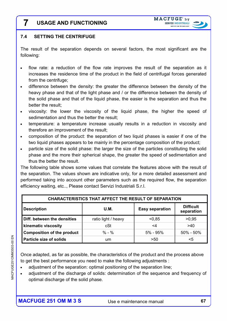
67 Use e maintenance manual
MA
CF
UG
E2
51O
MM
3S
03-0
0 E
N
MACFUGE 251 OM M 3 S
7.4 SETTING THE CENTRIFUGE
The result of the separation depends on several factors, the most significant are the
following:
flow rate: a reduction of the flow rate improves the result of the separation as it
increases the residence time of the product in the field of centrifugal forces generated
from the centrifuge;
difference between the density: the greater the difference between the density of the
heavy phase and that of the light phase and / or the difference between the density of
the solid phase and that of the liquid phase, the easier is the separation and thus the
better the result;
viscosity: the lower the viscosity of the liquid phase, the higher the speed of
sedimentation and thus the better the result;
temperature: a temperature increase usually results in a reduction in viscosity and
therefore an improvement of the result;
composition of the product: the separation of two liquid phases is easier if one of the
two liquid phases appears to be mainly in the percentage composition of the product;
particle size of the solid phase: the larger the size of the particles constituting the solid
phase and the more their spherical shape, the greater the speed of sedimentation and
thus the better the result.
The following table shows some values that correlate the features above with the result of
the separation. The values shown are indicative only, for a more detailed assessment and
performed taking into account other parameters such as the required flow, the separation
efficiency waiting, etc.., Please contact Servizi Industriali S.r.l.
Once adapted, as far as possible, the characteristics of the product and the process above
to get the best performance you need to make the following adjustments :
adjustment of the separation: optimal positioning of the separation line;
adjustment of the discharge of solids: determination of the sequence and frequency of
optimal discharge of the solid phase.
CHARACTERISTICS THAT AFFECT THE RESULT OF SEPARATION
Description U.M. Easy separation Difficult
separation
Diff. between the densities ratio light / heavy <0,85 >0,95
kinematic viscosity cSt <4 >40
Composition of the product % - % 5% - 95% 50% - 50%
Particle size of solids um >50 <5
7 USAGE AND FUNCTIONING
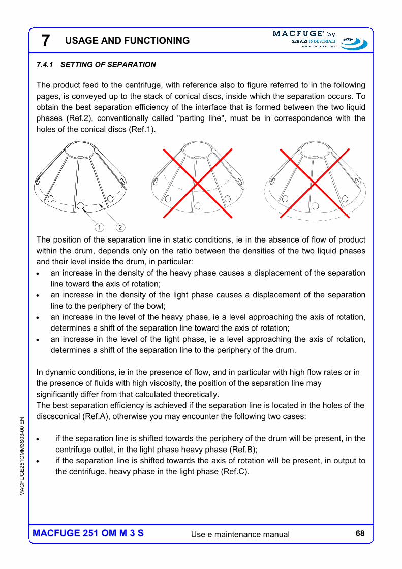
68 Use e maintenance manual
MA
CF
UG
E2
51O
MM
3S
03-0
0 E
N
MACFUGE 251 OM M 3 S
1 2
7.4.1 SETTING OF SEPARATION
The product feed to the centrifuge, with reference also to figure referred to in the following
pages, is conveyed up to the stack of conical discs, inside which the separation occurs. To
obtain the best separation efficiency of the interface that is formed between the two liquid
phases (Ref.2), conventionally called "parting line", must be in correspondence with the
holes of the conical discs (Ref.1).
The position of the separation line in static conditions, ie in the absence of flow of product
within the drum, depends only on the ratio between the densities of the two liquid phases
and their level inside the drum, in particular:
an increase in the density of the heavy phase causes a displacement of the separation
line toward the axis of rotation;
an increase in the density of the light phase causes a displacement of the separation
line to the periphery of the bowl;
an increase in the level of the heavy phase, ie a level approaching the axis of rotation,
determines a shift of the separation line toward the axis of rotation;
an increase in the level of the light phase, ie a level approaching the axis of rotation,
determines a shift of the separation line to the periphery of the drum.
In dynamic conditions, ie in the presence of flow, and in particular with high flow rates or in
the presence of fluids with high viscosity, the position of the separation line may
significantly differ from that calculated theoretically.
The best separation efficiency is achieved if the separation line is located in the holes of the
discsconical (Ref.A), otherwise you may encounter the following two cases:
if the separation line is shifted towards the periphery of the drum will be present, in the
centrifuge outlet, in the light phase heavy phase (Ref.B);
if the separation line is shifted towards the axis of rotation will be present, in output to
the centrifuge, heavy phase in the light phase (Ref.C).
7 USAGE AND FUNCTIONING
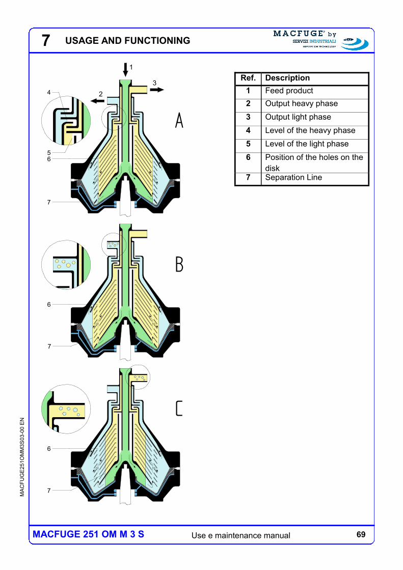
69 Use e maintenance manual
MA
CF
UG
E2
51O
MM
3S
03-0
0 E
N
MACFUGE 251 OM M 3 S
2
1
3
6
7
4
5
B
A
C
6
7
7
6
7 USAGE AND FUNCTIONING
Ref. Description
1 Feed product
2 Output heavy phase
3 Output light phase
4 Level of the heavy phase
5 Level of the light phase
6 Position of the holes on the
disk 7 Separation Line
70 Use e maintenance manual
MA
CF
UG
E2
51O
MM
3S
03-0
0 E
N
MACFUGE 251 OM M 3 S
Usually in a process of separation is considered binding the degree of purification of one of
the two phases, it is therefore convenient to adjust the position of the separation line in
such a way as to have residual traces of the phase useful in that not useful, in order to
ensure the better purification of the useful phase. For the positioning of the adjustment line
is possible to intervene on the following parameters:
diameter of the adjusting ring;
delivery pressure of the turbine.
The choice of the adjustment system most suitable depends on various factors described
below.
7 USAGE AND FUNCTIONING
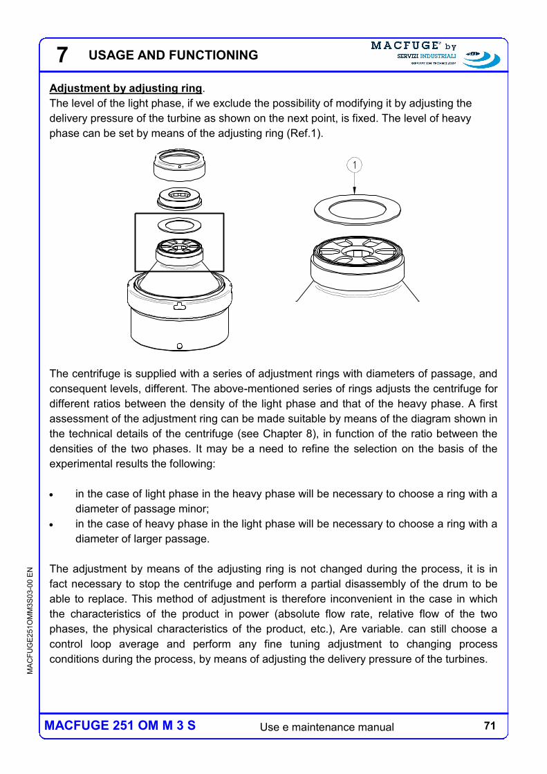
71 Use e maintenance manual
MA
CF
UG
E2
51O
MM
3S
03-0
0 E
N
MACFUGE 251 OM M 3 S
1
Adjustment by adjusting ring.
The level of the light phase, if we exclude the possibility of modifying it by adjusting the
delivery pressure of the turbine as shown on the next point, is fixed. The level of heavy
phase can be set by means of the adjusting ring (Ref.1).
The centrifuge is supplied with a series of adjustment rings with diameters of passage, and
consequent levels, different. The above-mentioned series of rings adjusts the centrifuge for
different ratios between the density of the light phase and that of the heavy phase. A first
assessment of the adjustment ring can be made suitable by means of the diagram shown in
the technical details of the centrifuge (see Chapter 8), in function of the ratio between the
densities of the two phases. It may be a need to refine the selection on the basis of the
experimental results the following:
in the case of light phase in the heavy phase will be necessary to choose a ring with a
diameter of passage minor;
in the case of heavy phase in the light phase will be necessary to choose a ring with a
diameter of larger passage.
The adjustment by means of the adjusting ring is not changed during the process, it is in
fact necessary to stop the centrifuge and perform a partial disassembly of the drum to be
able to replace. This method of adjustment is therefore inconvenient in the case in which
the characteristics of the product in power (absolute flow rate, relative flow of the two
phases, the physical characteristics of the product, etc.), Are variable. can still choose a
control loop average and perform any fine tuning adjustment to changing process
conditions during the process, by means of adjusting the delivery pressure of the turbines.
7 USAGE AND FUNCTIONING
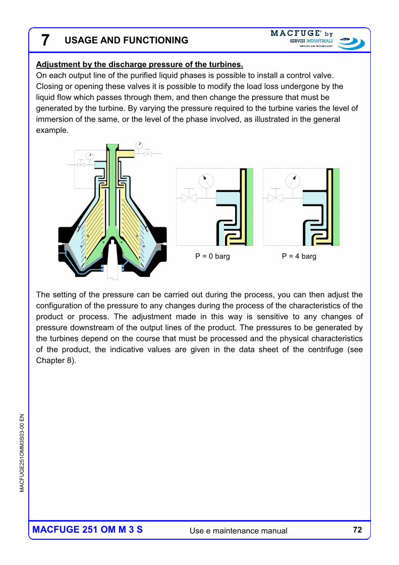
72 Use e maintenance manual
MA
CF
UG
E2
51O
MM
3S
03-0
0 E
N
MACFUGE 251 OM M 3 S
P = 4 bargP = 0 barg
Adjustment by the discharge pressure of the turbines.
On each output line of the purified liquid phases is possible to install a control valve.
Closing or opening these valves it is possible to modify the load loss undergone by the
liquid flow which passes through them, and then change the pressure that must be
generated by the turbine. By varying the pressure required to the turbine varies the level of
immersion of the same, or the level of the phase involved, as illustrated in the general
example.
The setting of the pressure can be carried out during the process, you can then adjust the
configuration of the pressure to any changes during the process of the characteristics of the
product or process. The adjustment made in this way is sensitive to any changes of
pressure downstream of the output lines of the product. The pressures to be generated by
the turbines depend on the course that must be processed and the physical characteristics
of the product, the indicative values are given in the data sheet of the centrifuge (see
Chapter 8).
7 USAGE AND FUNCTIONING
73 Use e maintenance manual
MA
CF
UG
E2
51O
MM
3S
03-0
0 E
N
MACFUGE 251 OM M 3 S
7.4.2 MANUAL DISCHARGE OF SOLIDS
The solid phase collected in the sludge chamber must be periodically removed (see
Par.2.4.1). The time interval between one cleaning and the next must be such as to ensure
that the sludge chamber does not arrive to never complete filling during use. The available
volume is specified in the data sheet of the centrifuge (see Chapter 8).
DANGER:
an excessive accumulation of solid can cause damage to the centrifuge and
create potentially dangerous situations for the things and people.
7 USAGE AND FUNCTIONING
74 Use e maintenance manual
MA
CF
UG
E2
51O
MM
3S
03-0
0 E
N
MACFUGE 251 OM M 3 S
7 USAGE AND FUNCTIONING
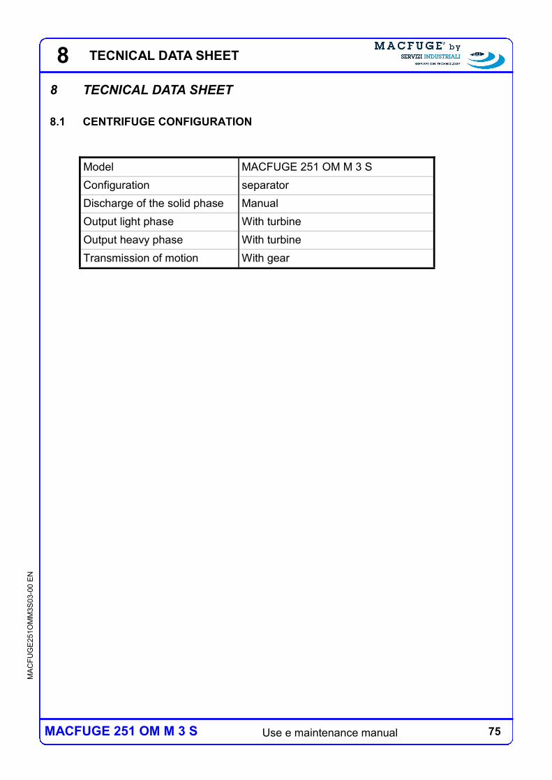
75 Use e maintenance manual
MA
CF
UG
E2
51O
MM
3S
03-0
0 E
N
MACFUGE 251 OM M 3 S
8 TECNICAL DATA SHEET
8 TECNICAL DATA SHEET
8.1 CENTRIFUGE CONFIGURATION
Model MACFUGE 251 OM M 3 S
Configuration separator
Discharge of the solid phase Manual
Output light phase With turbine
Output heavy phase With turbine
Transmission of motion With gear
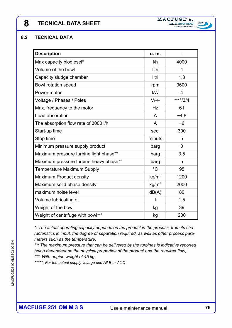
76 Use e maintenance manual
MA
CF
UG
E2
51O
MM
3S
03-0
0 E
N
MACFUGE 251 OM M 3 S
8.2 TECNICAL DATA
Description u. m. -
Max capacity biodiesel* l/h 4000
Volume of the bowl litri 4
Capacity sludge chamber litri 1,3
Bowl rotation speed rpm 9600
Power motor kW 4
Voltage / Phases / Poles V/-/- ****/3/4
Max. frequency to the motor Hz 61
Load absorption A ~4,8
The absorption flow rate of 3000 l/h A ~6
Start-up time sec. 300
Stop time minuts 5
Minimum pressure supply product barg 0
Maximum pressure turbine light phase** barg 3,5
Maximum pressure turbine heavy phase** barg 5
Temperature Maximum Supply °C 95
Maximum Product density kg/m3 1200
Maximum solid phase density kg/m3 2000
maximum noise level dB(A) 80
Volume lubricating oil l 1,5
Weight of the bowl kg 39
Weight of centrifuge with bowl*** kg 200
*: The actual operating capacity depends on the product in the process, from its cha-
racteristics in input, the degree of separation required, as well as other process para-
meters such as the temperature.
**: The maximum pressure that can be delivered by the turbines is indicative reported
being dependent on the physical properties of the product and the required flow;
***: With engine weight of 45 kg.
*****. For the actual supply voltage see All.B or All.C
8 TECNICAL DATA SHEET
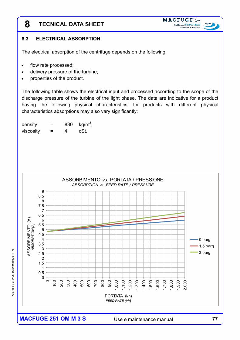
77 Use e maintenance manual
MA
CF
UG
E2
51O
MM
3S
03-0
0 E
N
MACFUGE 251 OM M 3 S
8.3 ELECTRICAL ABSORPTION
The electrical absorption of the centrifuge depends on the following:
flow rate processed;
delivery pressure of the turbine;
properties of the product.
The following table shows the electrical input and processed according to the scope of the
discharge pressure of the turbine of the light phase. The data are indicative for a product
having the following physical characteristics, for products with different physical
characteristics absorptions may also vary significantly:
density = 830 kg/m3;
viscosity = 4 cSt.
0
0,5
1
1,5
2
2,5
3
3,5
4
4,5
5
5,5
6
6,5
7
7,5
8
8,5
9
0
10
0
20
0
30
0
40
0
50
0
60
0
70
0
80
0
90
0
1.0
00
1.1
00
1.2
00
1.3
00
1.4
00
1.5
00
1.6
00
1.7
00
1.8
00
1.9
00
2.0
00
AS
SO
RB
IME
NTO
(A
)A
BS
OR
PT
ION
(A
)
PORTATA (l/h)FEED RATE (l/h)
ASSORBIMENTO vs. PORTATA / PRESSIONEABSORPTION vs. FEED RATE / PRESSURE
0 barg
1,5 barg
3 barg
8 TECNICAL DATA SHEET
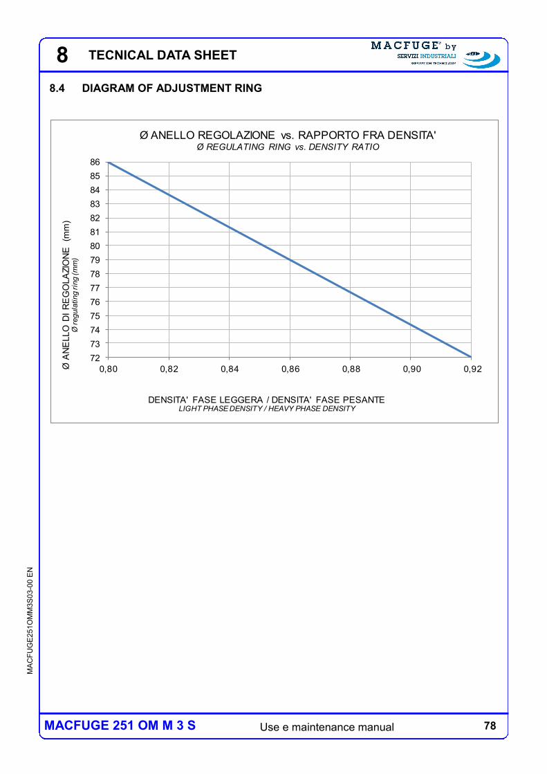
78 Use e maintenance manual
MA
CF
UG
E2
51O
MM
3S
03-0
0 E
N
MACFUGE 251 OM M 3 S
8.4 DIAGRAM OF ADJUSTMENT RING
72
73
74
75
76
77
78
79
80
81
82
83
84
85
86
0,80 0,82 0,84 0,86 0,88 0,90 0,92Ø A
NE
LLO
DI
RE
GO
LA
ZIO
NE
(m
m)
Ø regula
ting rin
g (m
m)
DENSITA' FASE LEGGERA / DENSITA' FASE PESANTELIGHT PHASE DENSITY / HEAVY PHASE DENSITY
Ø ANELLO REGOLAZIONE vs. RAPPORTO FRA DENSITA'Ø REGULATING RING vs. DENSITY RATIO
8 TECNICAL DATA SHEET
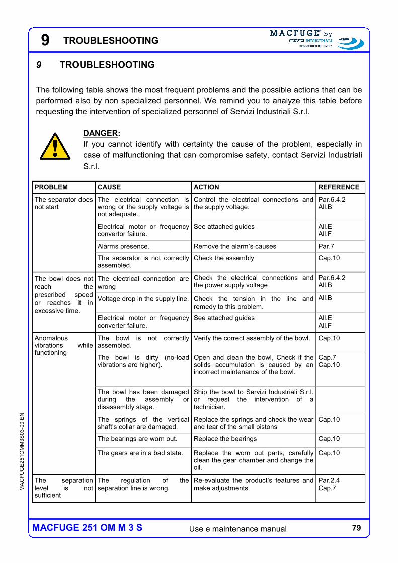
79 Use e maintenance manual
MA
CF
UG
E2
51O
MM
3S
03-0
0 E
N
MACFUGE 251 OM M 3 S
9
9 TROUBLESHOOTING
The following table shows the most frequent problems and the possible actions that can be
performed also by non specialized personnel. We remind you to analyze this table before
requesting the intervention of specialized personnel of Servizi Industriali S.r.l.
DANGER:
If you cannot identify with certainty the cause of the problem, especially in
case of malfunctioning that can compromise safety, contact Servizi Industriali
S.r.l.
PROBLEM CAUSE ACTION REFERENCE
The separator does not start
The electrical connection is wrong or the supply voltage is not adequate.
Control the electrical connections and the supply voltage.
Par.6.4.2 All.B
Electrical motor or frequency convertor failure.
See attached guides All.E All.F
Alarms presence. Remove the alarm’s causes Par.7
The separator is not correctly assembled.
Check the assembly Cap.10
The bowl does not
reach the
prescribed speed
or reaches it in
excessive time.
The electrical connection are
wrong
Check the electrical connections and the power supply voltage
Par.6.4.2 All.B
Voltage drop in the supply line. Check the tension in the line and
remedy to this problem.
All.B
Electrical motor or frequency converter failure.
See attached guides All.E All.F
Anomalous vibrations while functioning
The bowl is not correctly assembled.
Verify the correct assembly of the bowl. Cap.10
The bowl is dirty (no-load vibrations are higher).
Open and clean the bowl, Check if the solids accumulation is caused by an incorrect maintenance of the bowl.
Cap.7 Cap.10
The bowl has been damaged during the assembly or disassembly stage.
Ship the bowl to Servizi Industriali S.r.l. or request the intervention of a technician.
The springs of the vertical shaft’s collar are damaged.
Replace the springs and check the wear and tear of the small pistons
Cap.10
The bearings are worn out. Replace the bearings Cap.10
The gears are in a bad state. Replace the worn out parts, carefully clean the gear chamber and change the oil.
Cap.10
The separation level is not sufficient
The regulation of the separation line is wrong.
Re-evaluate the product’s features and make adjustments
Par.2.4 Cap.7
TROUBLESHOOTING
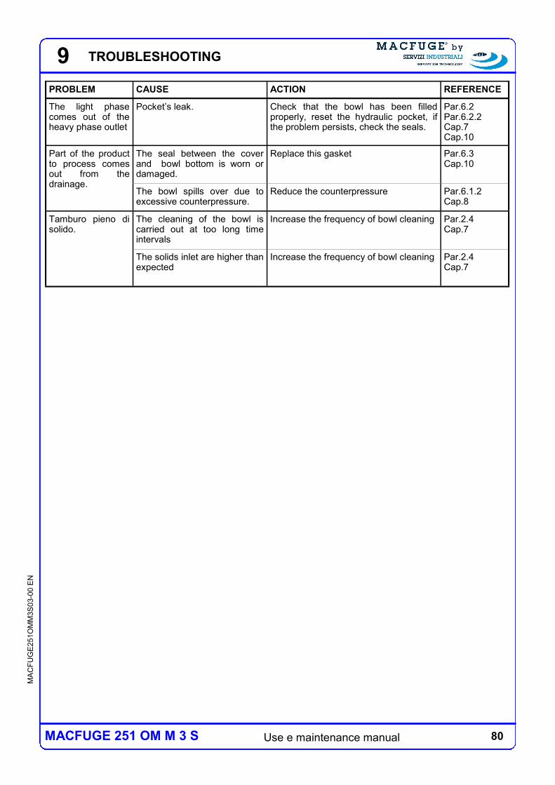
80 Use e maintenance manual
MA
CF
UG
E2
51O
MM
3S
03-0
0 E
N
MACFUGE 251 OM M 3 S
9
PROBLEM CAUSE ACTION REFERENCE
The light phase comes out of the heavy phase outlet
Pocket’s leak. Check that the bowl has been filled properly, reset the hydraulic pocket, if the problem persists, check the seals.
Par.6.2 Par.6.2.2 Cap.7 Cap.10
Part of the product to process comes out from the drainage.
The seal between the cover and bowl bottom is worn or damaged.
Replace this gasket Par.6.3 Cap.10
The bowl spills over due to excessive counterpressure.
Reduce the counterpressure Par.6.1.2 Cap.8
Tamburo pieno di solido.
The cleaning of the bowl is carried out at too long time intervals
Increase the frequency of bowl cleaning Par.2.4 Cap.7
The solids inlet are higher than expected
Increase the frequency of bowl cleaning Par.2.4 Cap.7
TROUBLESHOOTING
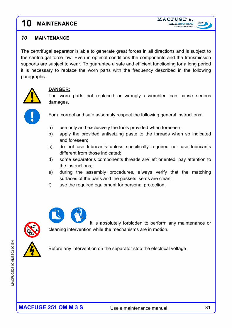
81 Use e maintenance manual
MA
CF
UG
E2
51O
MM
3S
03-0
0 E
N
MACFUGE 251 OM M 3 S
10
10 MAINTENANCE
The centrifugal separator is able to generate great forces in all directions and is subject to
the centrifugal force law. Even in optimal conditions the components and the transmission
supports are subject to wear. To guarantee a safe and efficient functioning for a long period
it is necessary to replace the worn parts with the frequency described in the following
paragraphs.
DANGER:
The worn parts not replaced or wrongly assembled can cause serious
damages.
For a correct and safe assembly respect the following general instructions:
a) use only and exclusively the tools provided when foreseen;
b) apply the provided antiseizing paste to the threads when so indicated
and foreseen;
c) do not use lubricants unless specifically required nor use lubricants
different from those indicated;
d) some separator’s components threads are left oriented; pay attention to
the instructions;
e) during the assembly procedures, always verify that the matching
surfaces of the parts and the gaskets’ seats are clean;
f) use the required equipment for personal protection.
It is absolutely forbidden to perform any maintenance or
cleaning intervention while the mechanisms are in motion.
Before any intervention on the separator stop the electrical voltage
MAINTENANCE
82 Use e maintenance manual
MA
CF
UG
E2
51O
MM
3S
03-0
0 E
N
MACFUGE 251 OM M 3 S
10
Maintenance is divided in two categories, ordinary and extraordinary:
ordinary maintenance: set of activities aimed at maintaining the use and functioning
conditions of the separator formed by the type of intervention described below,
performed by the operator and/or by the personnel responsible for the maintenance at
the established frequency.
extraordinary maintenance: set of activities aimed at maintaining the use and
functioning conditions of the separator formed by several types of intervention
exclusively performed by technicians working for the manufacturer and/or by authorized
assistance service centers, at the established frequency or in case of wear or
breakdown.
DANGER:
to guarantee a safe and efficient functioning of the separator, carefully respect
the deadlines and instructions prescribed for all maintenance interventions
and inspections.
Nel presente capitolo sono descritti gli interventi di manutenzione ordinaria, tali descrizioni
costituiscono il supporto tecnico al personale addetto alla manutenzione.
In the final pages of the manual (chapter 15) it is includes a table, named "Summary of
intervention and maintenance" for describing and recording the tasks performed on the
machine. It is mandatory fill out in detail the above table from who execute a significant
intervention on the machine including routine maintenance planned at least once a year,
being a local personal or Servizi Industriali's staff.
It is mandatory for the person performing a significant intervention on the
machine fill out in detail the table "Summary of intervention and maintenance"
MAINTENANCE
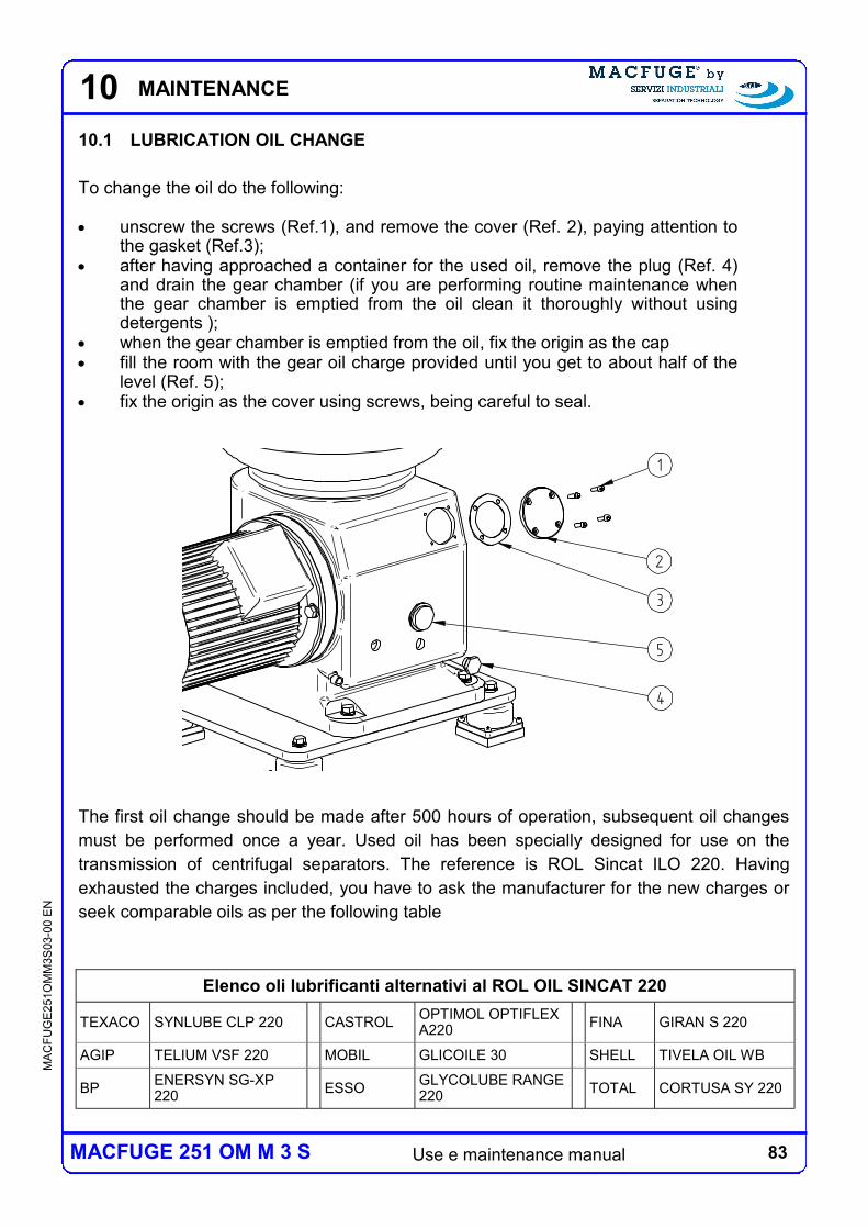
83 Use e maintenance manual
MA
CF
UG
E2
51O
MM
3S
03-0
0 E
N
MACFUGE 251 OM M 3 S
1
2
3
4
5
10.1 LUBRICATION OIL CHANGE
To change the oil do the following: unscrew the screws (Ref.1), and remove the cover (Ref. 2), paying attention to
the gasket (Ref.3); after having approached a container for the used oil, remove the plug (Ref. 4)
and drain the gear chamber (if you are performing routine maintenance when the gear chamber is emptied from the oil clean it thoroughly without using detergents );
when the gear chamber is emptied from the oil, fix the origin as the cap fill the room with the gear oil charge provided until you get to about half of the
level (Ref. 5); fix the origin as the cover using screws, being careful to seal.
The first oil change should be made after 500 hours of operation, subsequent oil changes
must be performed once a year. Used oil has been specially designed for use on the
transmission of centrifugal separators. The reference is ROL Sincat ILO 220. Having
exhausted the charges included, you have to ask the manufacturer for the new charges or
seek comparable oils as per the following table
Elenco oli lubrificanti alternativi al ROL OIL SINCAT 220
TEXACO SYNLUBE CLP 220 CASTROL OPTIMOL OPTIFLEX A220
FINA GIRAN S 220
AGIP TELIUM VSF 220 MOBIL GLICOILE 30 SHELL TIVELA OIL WB
BP ENERSYN SG-XP 220
ESSO GLYCOLUBE RANGE 220
TOTAL CORTUSA SY 220
10 MAINTENANCE
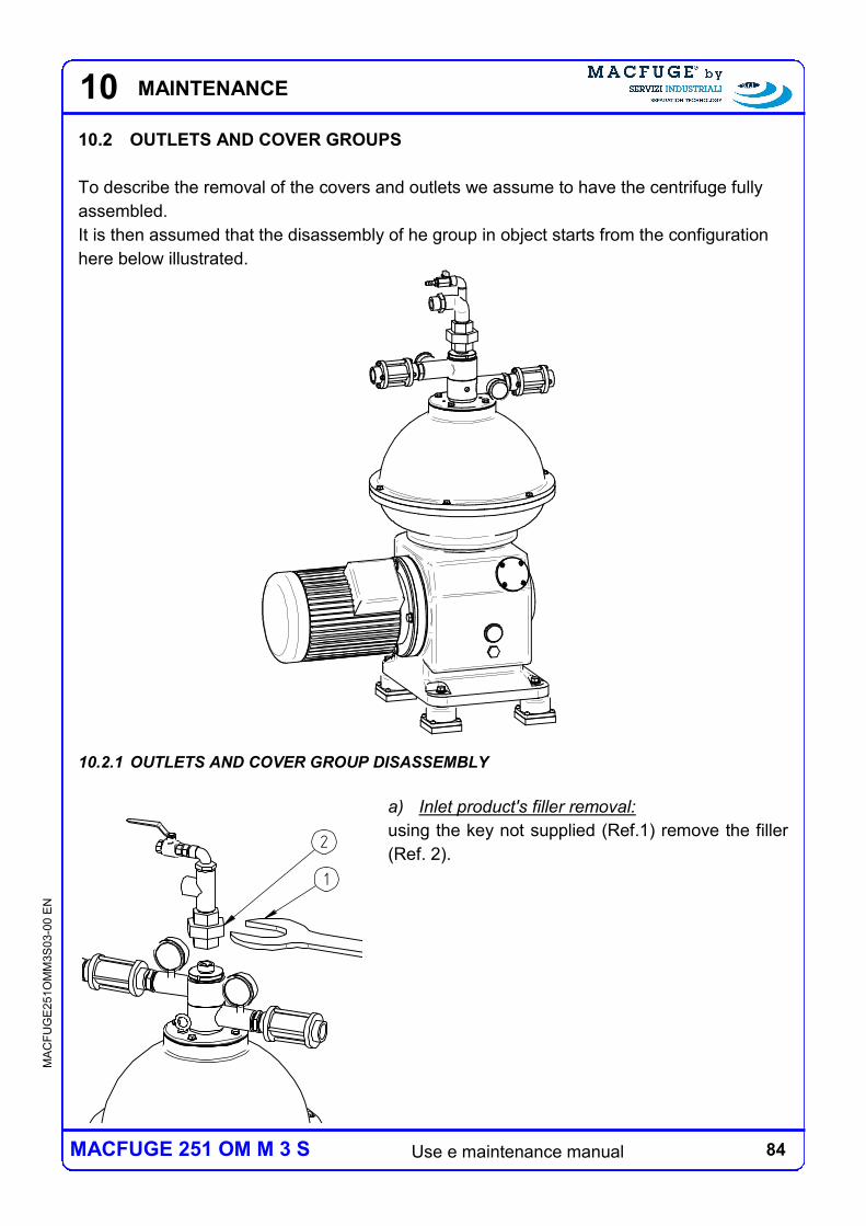
84 Use e maintenance manual
MA
CF
UG
E2
51O
MM
3S
03-0
0 E
N
MACFUGE 251 OM M 3 S
10
10.2 OUTLETS AND COVER GROUPS
To describe the removal of the covers and outlets we assume to have the centrifuge fully
assembled.
It is then assumed that the disassembly of he group in object starts from the configuration
here below illustrated.
10.2.1 OUTLETS AND COVER GROUP DISASSEMBLY
a) Inlet product's filler removal:
using the key not supplied (Ref.1) remove the filler
(Ref. 2).
1
2
MAINTENANCE
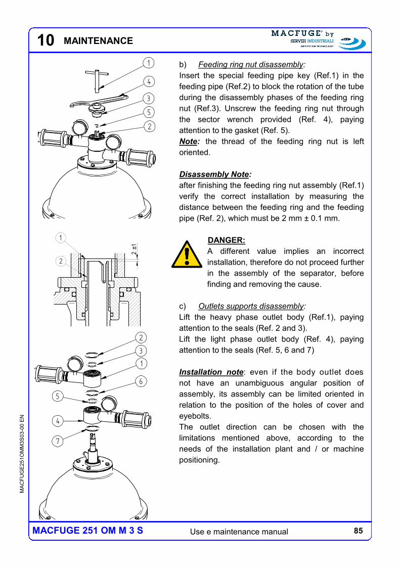
85 Use e maintenance manual
MA
CF
UG
E2
51O
MM
3S
03-0
0 E
N
MACFUGE 251 OM M 3 S
10
b) Feeding ring nut disassembly:
Insert the special feeding pipe key (Ref.1) in the
feeding pipe (Ref.2) to block the rotation of the tube
during the disassembly phases of the feeding ring
nut (Ref.3). Unscrew the feeding ring nut through
the sector wrench provided (Ref. 4), paying
attention to the gasket (Ref. 5).
Note: the thread of the feeding ring nut is left
oriented.
Disassembly Note:
after finishing the feeding ring nut assembly (Ref.1)
verify the correct installation by measuring the
distance between the feeding ring and the feeding
pipe (Ref. 2), which must be 2 mm ± 0.1 mm.
DANGER:
A different value implies an incorrect
installation, therefore do not proceed further
in the assembly of the separator, before
finding and removing the cause.
c) Outlets supports disassembly:
Lift the heavy phase outlet body (Ref.1), paying
attention to the seals (Ref. 2 and 3).
Lift the light phase outlet body (Ref. 4), paying
attention to the seals (Ref. 5, 6 and 7)
Installation note: even if the body outlet does
not have an unambiguous angular position of
assembly, its assembly can be limited oriented in
relation to the position of the holes of cover and
eyebolts.
The outlet direction can be chosen with the
limitations mentioned above, according to the
needs of the installation plant and / or machine
positioning.
1
4
3
5
2
1
3
2
6
4
5
7
MAINTENANCE
2±
1
1
2
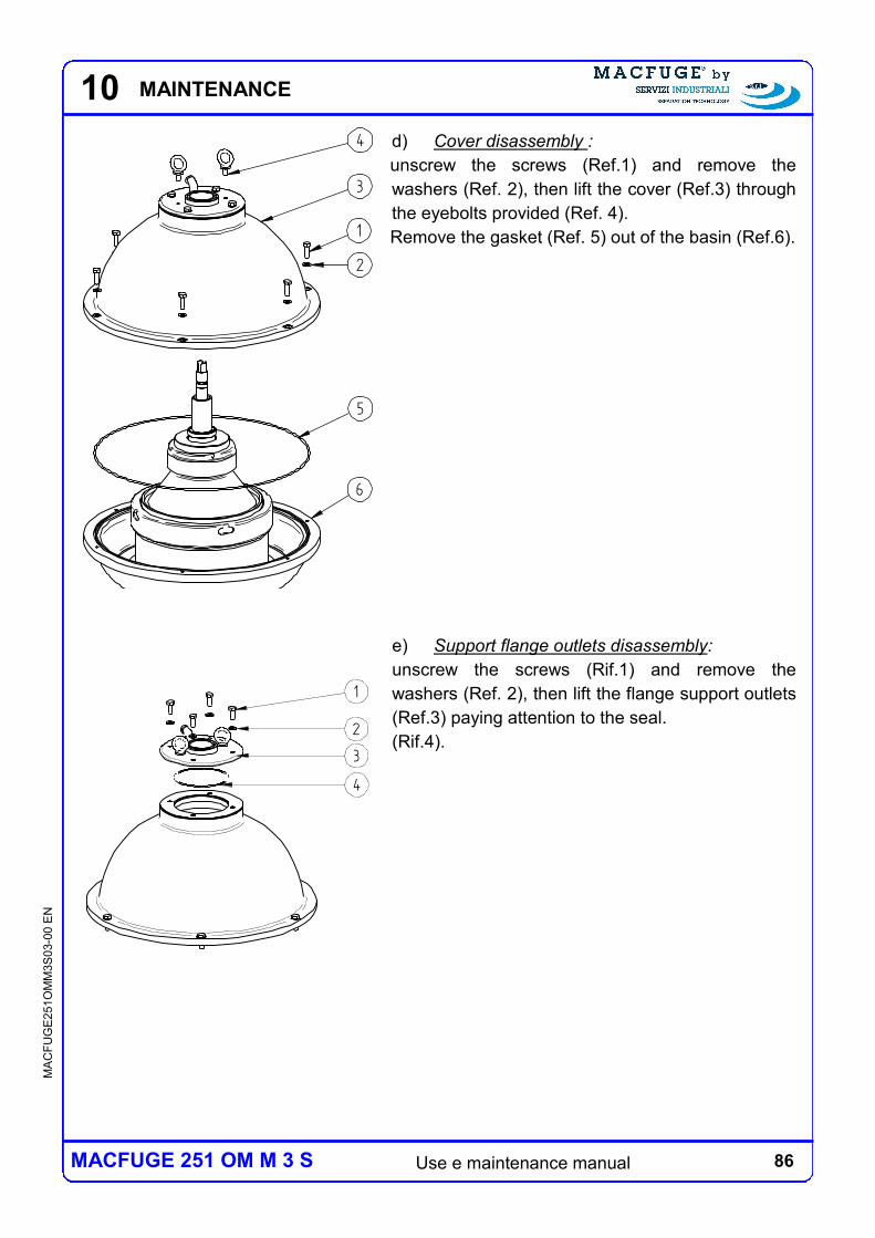
86 Use e maintenance manual
MA
CF
UG
E2
51O
MM
3S
03-0
0 E
N
MACFUGE 251 OM M 3 S
10
d) Cover disassembly :
unscrew the screws (Ref.1) and remove the
washers (Ref. 2), then lift the cover (Ref.3) through
the eyebolts provided (Ref. 4).
Remove the gasket (Ref. 5) out of the basin (Ref.6).
e) Support flange outlets disassembly:
unscrew the screws (Rif.1) and remove the
washers (Ref. 2), then lift the flange support outlets
(Ref.3) paying attention to the seal.
(Rif.4).
4
3
1
2
5
6
1
2
3
4
MAINTENANCE
87 Use e maintenance manual
MA
CF
UG
E2
51O
MM
3S
03-0
0 E
N
MACFUGE 251 OM M 3 S
10
10.2.2 PERIODICAL MAINTENANCE AND INSPECTIONS
Periodical maintenance
The prescribed periodical maintenance required for the cover group and outlets basically
consists in its cleaning and in the replacement of the seal elements that are damaged or no
longer functional. The cleaning must be performed together with the cleaning of the bowl
group and (at least for the parts that get in contact with the product) with the modalities
described below. With regard to the maintenance and periodical inspections related to the
turbine see following paragraphs.
Periodical inspections
While cleaning this group, also check with special attention to the presence of potential
corrosive and/or erosive phenomena.
MAINTENANCE
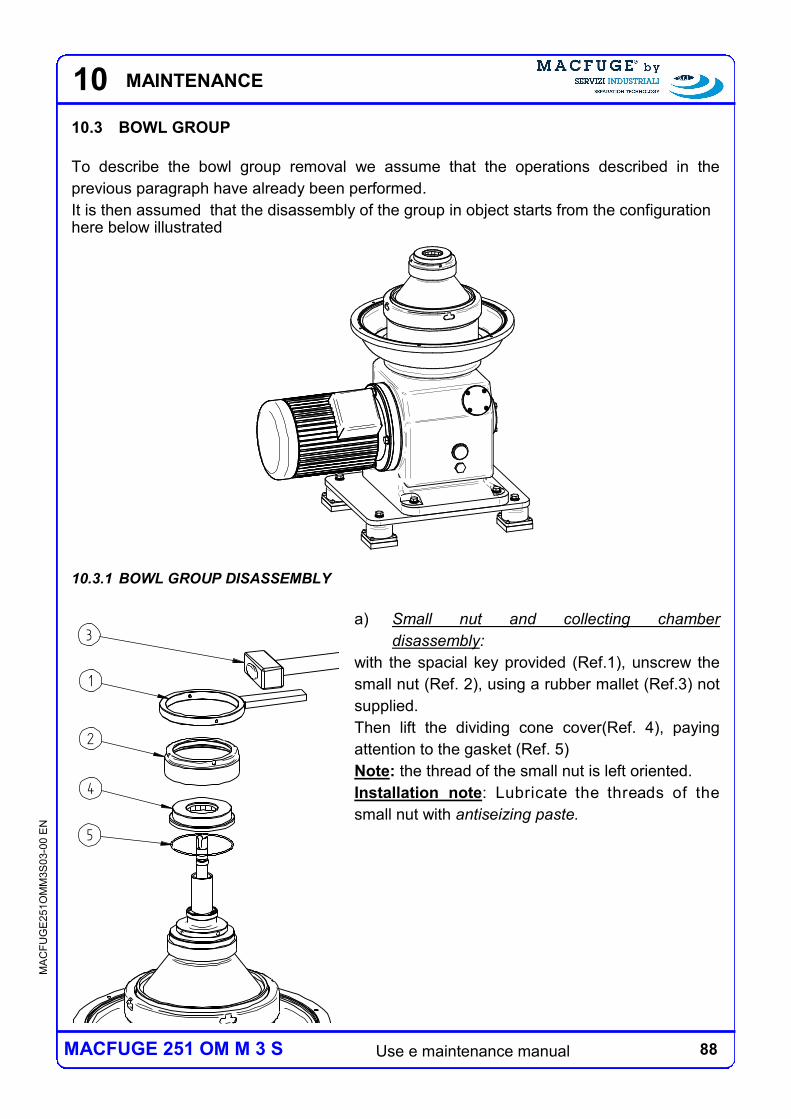
88 Use e maintenance manual
MA
CF
UG
E2
51O
MM
3S
03-0
0 E
N
MACFUGE 251 OM M 3 S
10
10.3 BOWL GROUP
To describe the bowl group removal we assume that the operations described in the
previous paragraph have already been performed.
It is then assumed that the disassembly of the group in object starts from the configuration here below illustrated
10.3.1 BOWL GROUP DISASSEMBLY
a) Small nut and collecting chamber
disassembly:
with the spacial key provided (Ref.1), unscrew the
small nut (Ref. 2), using a rubber mallet (Ref.3) not
supplied.
Then lift the dividing cone cover(Ref. 4), paying
attention to the gasket (Ref. 5)
Note: the thread of the small nut is left oriented.
Installation note: Lubricate the threads of the
small nut with antiseizing paste.
1
2
3
4
5
MAINTENANCE
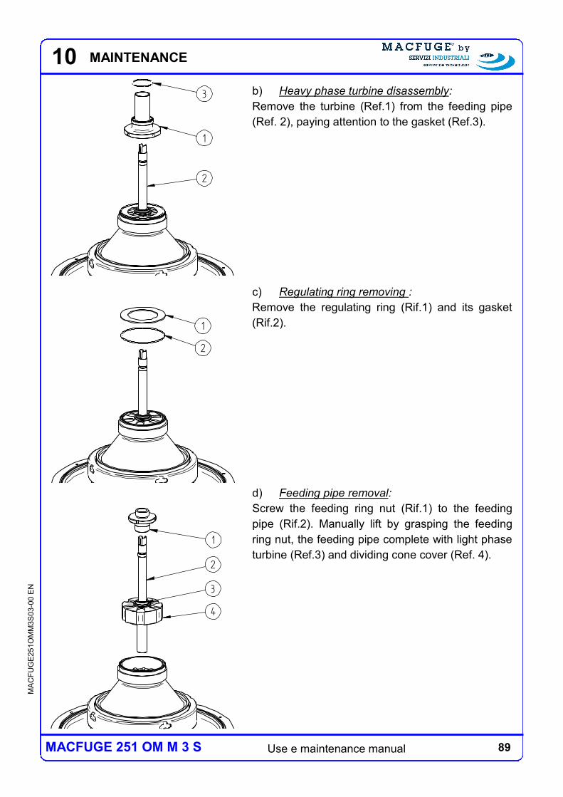
89 Use e maintenance manual
MA
CF
UG
E2
51O
MM
3S
03-0
0 E
N
MACFUGE 251 OM M 3 S
10
b) Heavy phase turbine disassembly:
Remove the turbine (Ref.1) from the feeding pipe
(Ref. 2), paying attention to the gasket (Ref.3).
c) Regulating ring removing :
Remove the regulating ring (Rif.1) and its gasket
(Rif.2).
d) Feeding pipe removal:
Screw the feeding ring nut (Rif.1) to the feeding
pipe (Rif.2). Manually lift by grasping the feeding
ring nut, the feeding pipe complete with light phase
turbine (Ref.3) and dividing cone cover (Ref. 4).
1
3
2
2
1
2
1
3
4
MAINTENANCE
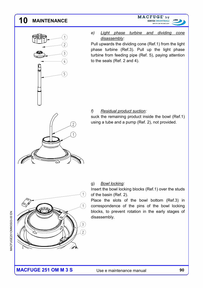
90 Use e maintenance manual
MA
CF
UG
E2
51O
MM
3S
03-0
0 E
N
MACFUGE 251 OM M 3 S
10
e) Light phase turbine and dividing cone
disassembly:
Pull upwards the dividing cone (Ref.1) from the light
phase turbine (Ref.3). Pull up the light phase
turbine from feeding pipe (Ref. 5), paying attention
to the seals (Ref. 2 and 4).
f) Residual product suction:
suck the remaining product inside the bowl (Ref.1)
using a tube and a pump (Ref. 2), not provided.
g) Bowl locking:
Insert the bowl locking blocks (Ref.1) over the studs
of the basin (Ref. 2).
Place the slots of the bowl bottom (Ref.3) in
correspondence of the pins of the bowl locking
blocks, to prevent rotation in the early stages of
disassembly.
1
2
3
4
5
2
1
2
1
1
3
MAINTENANCE
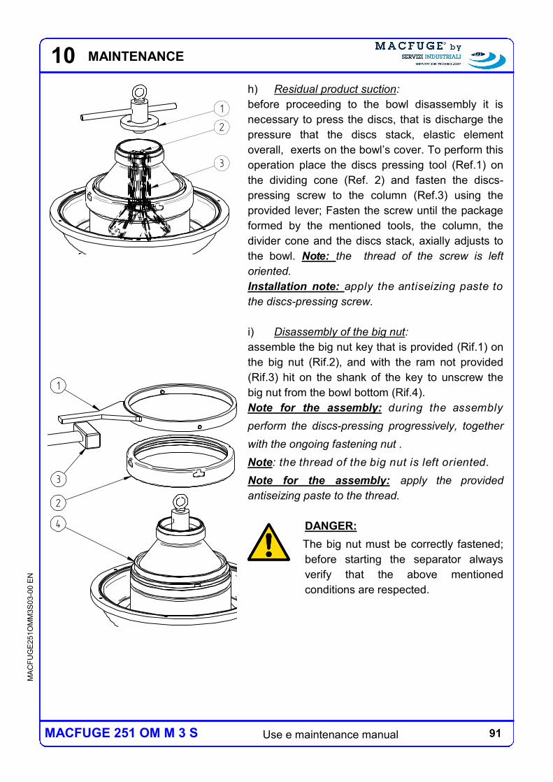
91 Use e maintenance manual
MA
CF
UG
E2
51O
MM
3S
03-0
0 E
N
MACFUGE 251 OM M 3 S
10
h) Residual product suction:
before proceeding to the bowl disassembly it is
necessary to press the discs, that is discharge the
pressure that the discs stack, elastic element
overall, exerts on the bowl’s cover. To perform this
operation place the discs pressing tool (Ref.1) on
the dividing cone (Ref. 2) and fasten the discs-
pressing screw to the column (Ref.3) using the
provided lever; Fasten the screw until the package
formed by the mentioned tools, the column, the
divider cone and the discs stack, axially adjusts to
the bowl. Note: the thread of the screw is left
oriented.
Installation note: apply the antiseizing paste to
the discs-pressing screw.
i) Disassembly of the big nut:
assemble the big nut key that is provided (Rif.1) on
the big nut (Rif.2), and with the ram not provided
(Rif.3) hit on the shank of the key to unscrew the
big nut from the bowl bottom (Rif.4).
Note for the assembly: during the assembly
perform the discs-pressing progressively, together
with the ongoing fastening nut .
Note: the thread of the big nut is left oriented.
Note for the assembly: apply the provided
antiseizing paste to the thread.
DANGER:
The big nut must be correctly fastened;
before starting the separator always
verify that the above mentioned
conditions are respected.
1
2
3
3
1
2
4
MAINTENANCE
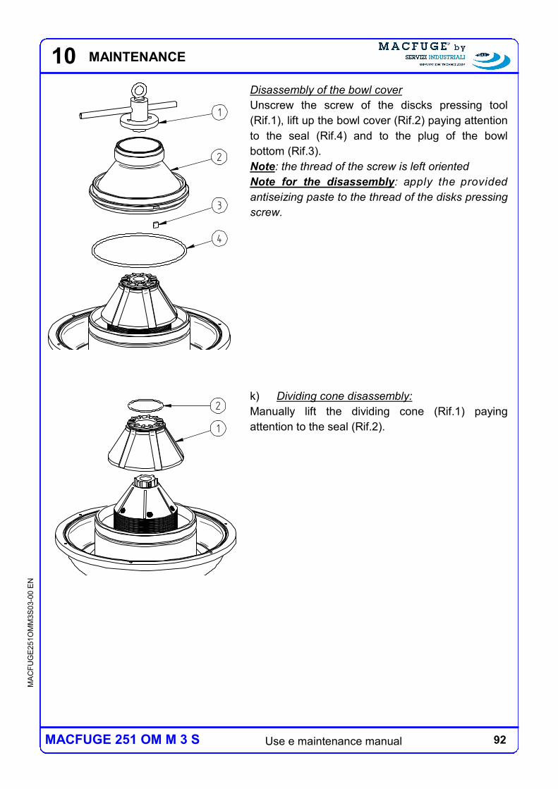
92 Use e maintenance manual
MA
CF
UG
E2
51O
MM
3S
03-0
0 E
N
MACFUGE 251 OM M 3 S
10
Disassembly of the bowl cover
Unscrew the screw of the discks pressing tool
(Rif.1), lift up the bowl cover (Rif.2) paying attention
to the seal (Rif.4) and to the plug of the bowl
bottom (Rif.3).
Note: the thread of the screw is left oriented
Note for the disassembly: apply the provided
antiseizing paste to the thread of the disks pressing
screw.
k) Dividing cone disassembly:
Manually lift the dividing cone (Rif.1) paying
attention to the seal (Rif.2).
1
2
3
4
2
1
MAINTENANCE
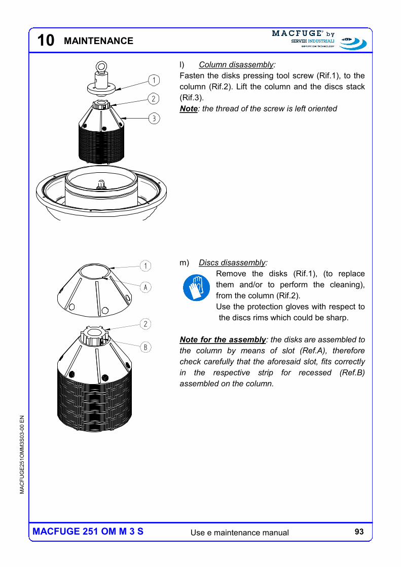
93 Use e maintenance manual
MA
CF
UG
E2
51O
MM
3S
03-0
0 E
N
MACFUGE 251 OM M 3 S
10
l) Column disassembly:
Fasten the disks pressing tool screw (Rif.1), to the
column (Rif.2). Lift the column and the discs stack
(Rif.3).
Note: the thread of the screw is left oriented
m) Discs disassembly:
Remove the disks (Rif.1), (to replace
them and/or to perform the cleaning),
from the column (Rif.2).
Use the protection gloves with respect to
the discs rims which could be sharp.
Note for the assembly: the disks are assembled to
the column by means of slot (Ref.A), therefore
check carefully that the aforesaid slot, fits correctly
in the respective strip for recessed (Ref.B)
assembled on the column.
1
2
3
1
A
B
2
MAINTENANCE
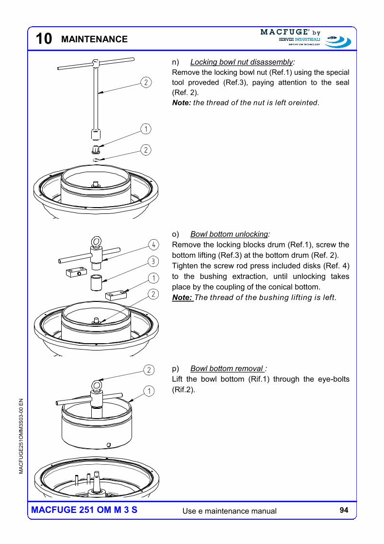
94 Use e maintenance manual
MA
CF
UG
E2
51O
MM
3S
03-0
0 E
N
MACFUGE 251 OM M 3 S
10
n) Locking bowl nut disassembly:
Remove the locking bowl nut (Ref.1) using the special
tool proveded (Ref.3), paying attention to the seal
(Ref. 2).
Note: the thread of the nut is left oreinted.
o) Bowl bottom unlocking:
Remove the locking blocks drum (Ref.1), screw the
bottom lifting (Ref.3) at the bottom drum (Ref. 2).
Tighten the screw rod press included disks (Ref. 4)
to the bushing extraction, until unlocking takes
place by the coupling of the conical bottom.
Note: The thread of the bushing lifting is left.
p) Bowl bottom removal :
Lift the bowl bottom (Rif.1) through the eye-bolts
(Rif.2).
2
1
2
1
2
3
4
2
1
MAINTENANCE
95 Use e maintenance manual
MA
CF
UG
E2
51O
MM
3S
03-0
0 E
N
MACFUGE 251 OM M 3 S
10
10.3.2 BOWL CLEANING
Even though with different frequency and modalities, the bowl cleaning must be performed
both on the line and on the disassembled bowl.
Cleaning on the line
The cleaning on the line can be performed by supplying the separator with water, preferably
hot, eventually with the addition of a mild alkaline detergent .
Cleaning with disassembled bowl
Once the bowl has been disassembled, as described in the following chapters wash the
parts forming the bowl in the following procedure:
immerge the parts in warm water and wash them with an alkaline detergent;
brush the parts, when necessary; never use hard materials brushes for example do
not use a steel wool;
rinse abundantly with clean water;
dry the parts, or let them dry, before reassembling the bowl.
It is absolutely forbidden to use chlorine compounds, in particular hydrochloric
acid, in any phase of the washing cycle due to the corrosive properties of
these substances with respect to inoxidizable steel.
The required frequency of the cleaning with disassembled bowl depends on the features of
the processed product and on the usage modalities of the separator (discharge frequency
during process, cleaning frequency, etc.). Perform a first maintenance, inspection and
cleaning intervention on the disassembled bowl after the first 40 working hours and then,
progressively, modify the amount of working time before the required next cleaning based
on the bowl’s conditions, in particular in function of the amount of solid which has
accumulated in the sedimentation chamber.
It is prescribed to perform a maintenance, inspection and cleaning intervention
on the bowl after the first 8 working hours, then after the first 40 working hours
and then perform at least one intervention every 500 working hours or once a
year.
MAINTENANCE
96 Use e maintenance manual
MA
CF
UG
E2
51O
MM
3S
03-0
0 E
N
MACFUGE 251 OM M 3 S
10
DANGER:
Perform the cleaning stage with a frequency sufficient to ensure that an
excessive accumulation of solids does not accrue in the sedimentation chamber;
an excessive accumulation of solids can generate a falling of the performance,
up to complete occlusion of the bowl, generating situations of damage to the
centrifuge and dangerous situations for the operator
If your experience shows that the required frequency of disassembled bowl’s cleaning is
higher than the one prescribed for the maintenance and inspection intervention, it is
sufficient to disassemble the bowl up to the discs disassembly. Once the cleaning is
completed, before reassembling the bowl verify the seal of all seal elements — compatibly
with the disassembly stage reached, and replace them when necessary. Furthermore,
perform all the inspections scheduled, again compatibly with the disassembly stage
reached.
MAINTENANCE
97 Use e maintenance manual
MA
CF
UG
E2
51O
MM
3S
03-0
0 E
N
MACFUGE 251 OM M 3 S
10
10.3.3 MAINTENANCE AND PERIODICAL INSPECTIONS
DANGER:
respect very carefully the deadlines for the maintenance and inspection
interventions in order to immediately identify the possible presence of
corrosive and/or erosive processes, avoid their progression and the creation of
highly dangerous situations.
Manutenzioni periodiche
The periodical maintenance required for the bowl group basically consists in its cleaning,
and in the replacement of the seal elements that are damaged or no longer functional.
Wash with particular care the turbine channels of product’s passage.
Periodical inspections.
The periodical inspections of the parts forming the bowl are very important for the safety of
people and things and must be performed according to the deadlines previously described.
We here describe the controls that must be performed, with special attention to the
presence of potential corrosive and/or erosive phenomena, in particular check the status of
the turbine at the entry points of the liquid phases and replace the turbine if the wear were
such as compromising its functionality.
inspection of the conditions of the external and internal surfaces of all bowl’s structural
elements (bowl bottom, big nut blocking);
inspection of the conditions of the surfaces on the bowl’s group with special attention
to the presence of potential corrosive and/or erosive phenomena;
inspection of the wear and tear conditions of the matching surfaces on the bowl's
group with special attention to possible erosions;
inspection of the threads for the matching with lifting tools
MAINTENANCE
98 Use e maintenance manual
MA
CF
UG
E2
51O
MM
3S
03-0
0 E
N
MACFUGE 251 OM M 3 S
10
If the presence of any erosive/corrosive phenomena in any of the bowl’s
structural parts (bowl bottom, big nut locking) arises during the inspections
here described, do not use the separator and immediately contact Servizi
Industriali.
It is absolutely forbidden to repair the rotating parts through welding.
MAINTENANCE
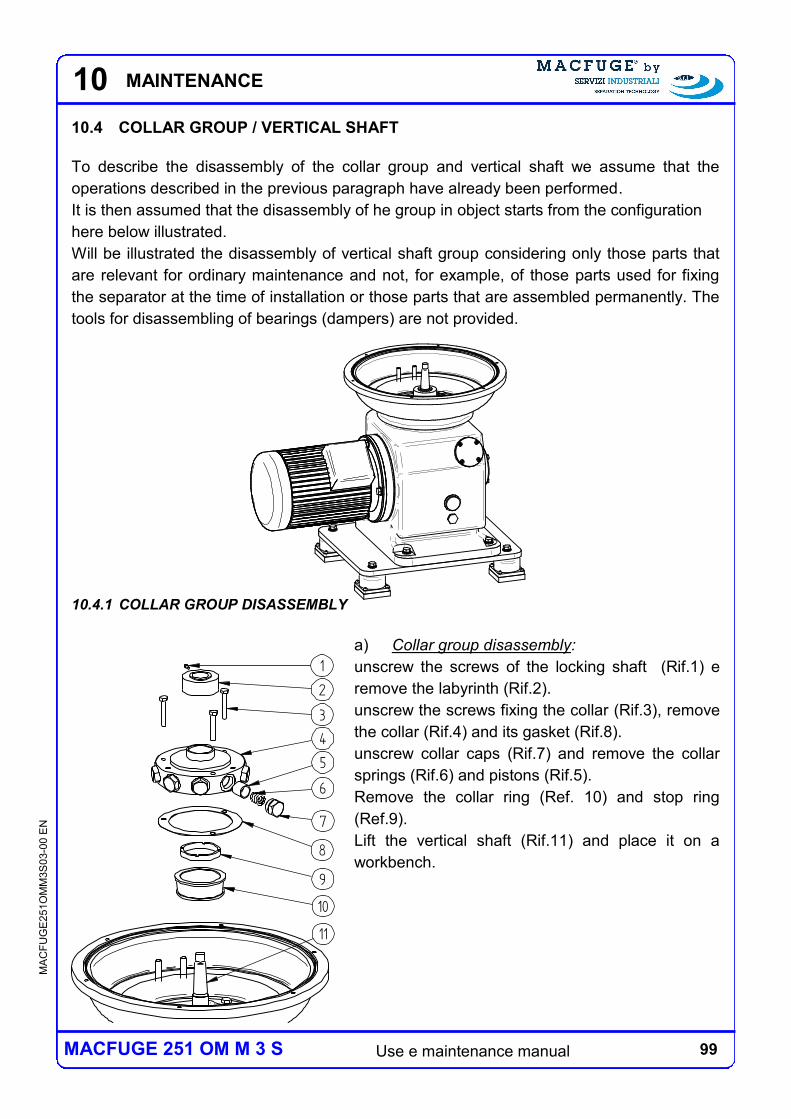
99 Use e maintenance manual
MA
CF
UG
E2
51O
MM
3S
03-0
0 E
N
MACFUGE 251 OM M 3 S
10
10.4 COLLAR GROUP / VERTICAL SHAFT
To describe the disassembly of the collar group and vertical shaft we assume that the
operations described in the previous paragraph have already been performed.
It is then assumed that the disassembly of he group in object starts from the configuration
here below illustrated.
Will be illustrated the disassembly of vertical shaft group considering only those parts that
are relevant for ordinary maintenance and not, for example, of those parts used for fixing
the separator at the time of installation or those parts that are assembled permanently. The
tools for disassembling of bearings (dampers) are not provided.
10.4.1 COLLAR GROUP DISASSEMBLY
a) Collar group disassembly:
unscrew the screws of the locking shaft (Rif.1) e
remove the labyrinth (Rif.2).
unscrew the screws fixing the collar (Rif.3), remove
the collar (Rif.4) and its gasket (Rif.8).
unscrew collar caps (Rif.7) and remove the collar
springs (Rif.6) and pistons (Rif.5).
Remove the collar ring (Ref. 10) and stop ring
(Ref.9).
Lift the vertical shaft (Rif.11) and place it on a
workbench.
1
2
3
4
8
9
10
5
6
7
11
MAINTENANCE
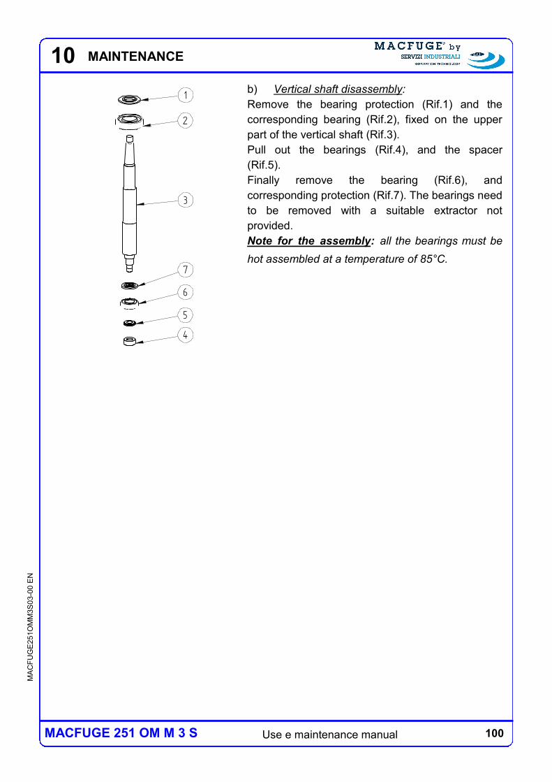
100 Use e maintenance manual
MA
CF
UG
E2
51O
MM
3S
03-0
0 E
N
MACFUGE 251 OM M 3 S
10
b) Vertical shaft disassembly:
Remove the bearing protection (Rif.1) and the
corresponding bearing (Rif.2), fixed on the upper
part of the vertical shaft (Rif.3).
Pull out the bearings (Rif.4), and the spacer
(Rif.5).
Finally remove the bearing (Rif.6), and
corresponding protection (Rif.7). The bearings need
to be removed with a suitable extractor not
provided.
Note for the assembly: all the bearings must be
hot assembled at a temperature of 85°C.
1
2
3
4
5
6
7
MAINTENANCE
101 Use e maintenance manual
MA
CF
UG
E2
51O
MM
3S
03-0
0 E
N
MACFUGE 251 OM M 3 S
10
10.4.2 MAINTENANCE AND PERIODICAL INSPECTIONS
Periodical maintenance
The periodical maintenance prescribed for the vertical shaft group / collar group are here
below described:
The first lubricant oil change have to be done after 500 working hours or at least once
a year;
replace the bearings once a year.
Periodical Inspections
The periodical inspections prescribed for the vertical shaft group / collar group are here
below described:
During the replacement of the parts referred to periodical maintenance, check before
each start-up of the lubricating oil level, make sure that to the oil is not contaminated
with water, check the state of wear of the vertical shaft, the pistons and springs, all of
the sealing elements, and then to replace them if necessary.
MAINTENANCE
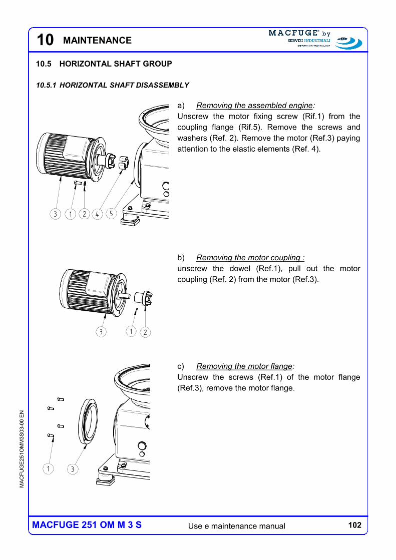
102 Use e maintenance manual
MA
CF
UG
E2
51O
MM
3S
03-0
0 E
N
MACFUGE 251 OM M 3 S
10
10.5 HORIZONTAL SHAFT GROUP
10.5.1 HORIZONTAL SHAFT DISASSEMBLY
a) Removing the assembled engine:
Unscrew the motor fixing screw (Rif.1) from the
coupling flange (Rif.5). Remove the screws and
washers (Ref. 2). Remove the motor (Ref.3) paying
attention to the elastic elements (Ref. 4).
b) Removing the motor coupling :
unscrew the dowel (Ref.1), pull out the motor
coupling (Ref. 2) from the motor (Ref.3).
c) Removing the motor flange:
Unscrew the screws (Ref.1) of the motor flange
(Ref.3), remove the motor flange.
MAINTENANCE
1 23
1 23 4 5
1 3
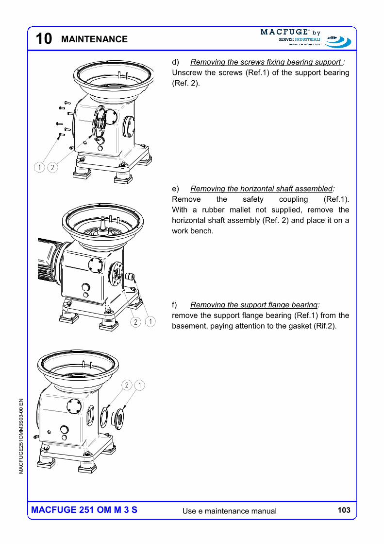
103 Use e maintenance manual
MA
CF
UG
E2
51O
MM
3S
03-0
0 E
N
MACFUGE 251 OM M 3 S
10
d) Removing the screws fixing bearing support :
Unscrew the screws (Ref.1) of the support bearing
(Ref. 2).
e) Removing the horizontal shaft assembled:
Remove the safety coupling (Ref.1).
With a rubber mallet not supplied, remove the
horizontal shaft assembly (Ref. 2) and place it on a
work bench.
f) Removing the support flange bearing:
remove the support flange bearing (Ref.1) from the
basement, paying attention to the gasket (Rif.2).
1 2
2 1
MAINTENANCE
12
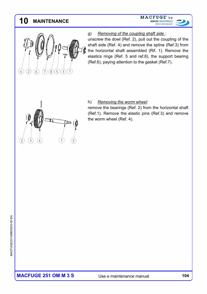
104 Use e maintenance manual
MA
CF
UG
E2
51O
MM
3S
03-0
0 E
N
MACFUGE 251 OM M 3 S
10
g) Removing of the coupling shaft side :
unscrew the dowl (Ref. 2), pull out the coupling of the
shaft side (Ref. 4) and remove the spline (Ref.3) from
the horizontal shaft assembled (Rif. 1). Remove the
elastics rings (Ref. 5 and ref.8), the support bearing
(Ref.6), paying attention to the gasket (Ref.7).
h) Removing the worm wheel:
remove the bearings (Ref. 2) from the horizontal shaft
(Ref.1). Remove the elastic pins (Ref.3) and remove
the worm wheel (Ref. 4).
13587624
2 3 4 1 2
MAINTENANCE
105 Use e maintenance manual
MA
CF
UG
E2
51O
MM
3S
03-0
0 E
N
MACFUGE 251 OM M 3 S
10
10.5.2 MAINTENANCE AND PERIODICAL INSPECTIONS
Periodical maintenance
The periodical maintenance prescribed for the horizontal shaft group are here below
described:
The first lubricant oil change have to be done after 500 working hours or at least once
a year;
replace the bearings once a year.
Periodical Inspections
The periodical inspections prescribed for the horizontal shaft group are here below
described:
During the replacement of the parts referred to periodical maintenance, check before
each start-up of the lubricating oil level, make sure that to the oil is not contaminated
with water, check the state of wear of the vertical shaft, the pistons and springs, all of
the sealing elements, and then to replace them if necessary.
MAINTENANCE
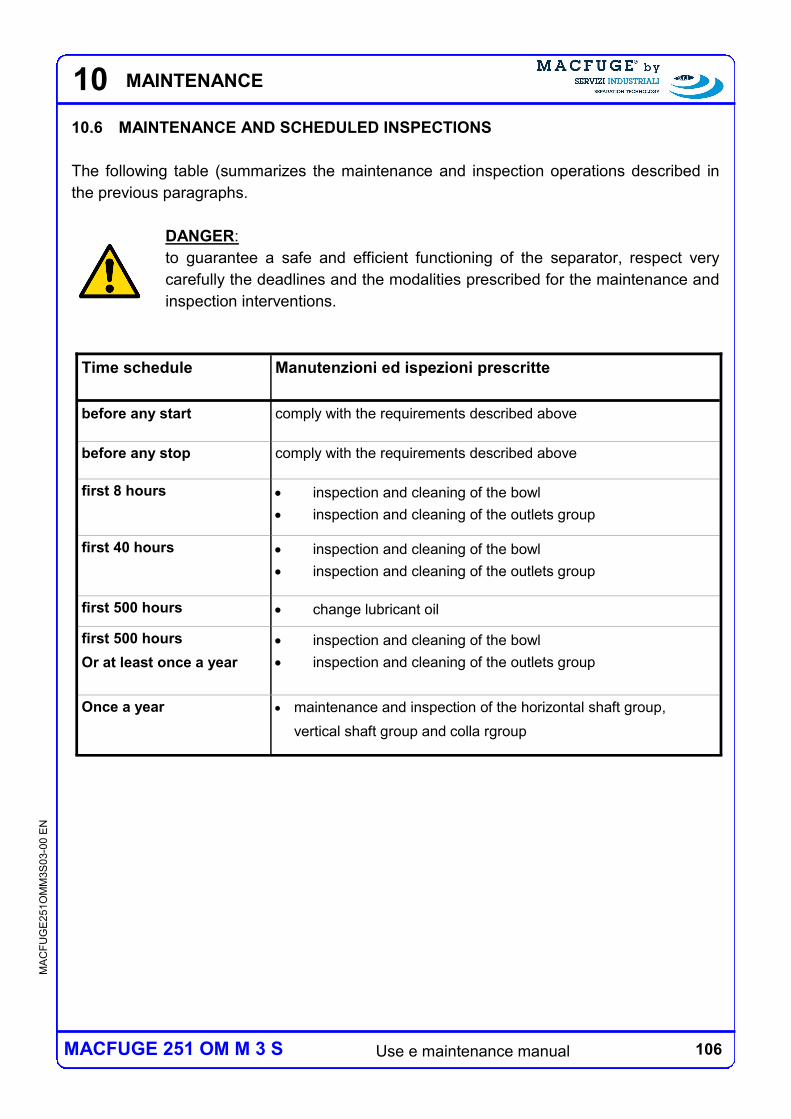
106 Use e maintenance manual
MA
CF
UG
E2
51O
MM
3S
03-0
0 E
N
MACFUGE 251 OM M 3 S
10
10.6 MAINTENANCE AND SCHEDULED INSPECTIONS
The following table (summarizes the maintenance and inspection operations described in
the previous paragraphs.
DANGER:
to guarantee a safe and efficient functioning of the separator, respect very
carefully the deadlines and the modalities prescribed for the maintenance and
inspection interventions.
Time schedule Manutenzioni ed ispezioni prescritte
before any start comply with the requirements described above
before any stop comply with the requirements described above
first 8 hours inspection and cleaning of the bowl
inspection and cleaning of the outlets group
first 40 hours inspection and cleaning of the bowl
inspection and cleaning of the outlets group
first 500 hours change lubricant oil
first 500 hours
Or at least once a year
inspection and cleaning of the bowl
inspection and cleaning of the outlets group
Once a year maintenance and inspection of the horizontal shaft group,
vertical shaft group and colla rgroup
MAINTENANCE
107 Use e maintenance manual
MA
CF
UG
E2
51O
MM
3S
03-0
0 E
N
MACFUGE 251 OM M 3 S
11
11 DEMOLITION
When dismantling the centrifuge it is mandatory to follow the laws of the
country where the dismantling takes place and separate the parts composing
the centrifuge according to the different type of building materials (plastic,
copper, iron, etc.).
Lubricant liquids and other potentially polluting fluids cannot be discharged in
the environment but must be disposed by authorized companies specialized in
the dismantling of the different type of products.
DEMOLITION
Use and care guide

108 Use e maintenance manual
MA
CF
UG
E2
51O
MM
3S
03-0
0 E
N
MACFUGE 251 OM M 3 S
11 DEMOLITION
109 Use e maintenance manual
MA
CF
UG
E2
51O
MM
3S
03-0
0 E
N
MACFUGE 251 OM M 3 S
12 PARTS LIST
12 PARTS LIST
To guarantee perfect operation of the centrifuge in the long time you must maintenance
operations with the times and in the manner described in this manual. If you need
replacement parts please do not hesitate to do it and especially use original spare parts
supplied by the manufacturer.
When ordering spare parts, please always specify:
model of the centrifuge;
serial number;
description of the part to be ordered, relevant reference code and quantity required;
clearly indicate the full legal name of fiscal data;
indicate the destination of the centrifuge;
indicate the means of transport required.
In Par.13.2 shows a module orders spare parts to be used for the request.
12.1 VARIATIONS TO THE PARTS LIST
The list of parts shown in the tables and the tables below refers to the standard
configuration of the centrifuge. Some groups may vary as a result of specific customer
requests (eg for the type of input and output connections), the need for installation tools or
insertion of the centrifuge in a system more complex. The above any changes are set out in
Chapter 14 In the event that a facility is provided, more detailed information is also included
in the manual of use and maintenance of the plant.
110 Use e maintenance manual
MA
CF
UG
E2
51O
MM
3S
03-0
0 E
N
MACFUGE 251 OM M 3 S
12 PARTS LIST
12.2 MACHINES GROUPS
The constituent parts of the centrifugal separator are conventionally grouped together for ease
of management and explanatory, the following groups:
horizontal shaft group (Tav.1);
vertical shaft group (Tav.2);
collar group (Tav.3);
covers group (Tav.4);
bowl group (Tav.5);
outlets group (Tav.6);
tools group (Tav.7).

111 Use e maintenance manual
MA
CF
UG
E2
51O
MM
3S
03-0
0 E
N
MACFUGE 251 OM M 3 S
12 PARTS LIST
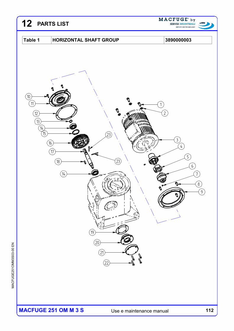
112 Use e maintenance manual
MA
CF
UG
E2
51O
MM
3S
03-0
0 E
N
MACFUGE 251 OM M 3 S
12 PARTS LIST
Table 1 HORIZONTAL SHAFT GROUP 3890000003
15
4
3
18
11
10
17
16
19
12
20
9
5
21
7
6
8
23
23
14
22
13
14
1
2
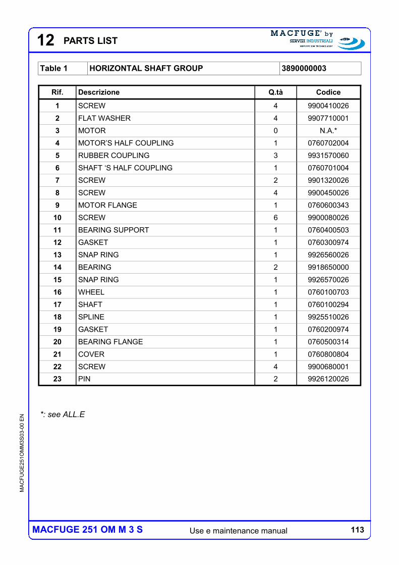
113 Use e maintenance manual
MA
CF
UG
E2
51O
MM
3S
03-0
0 E
N
MACFUGE 251 OM M 3 S
12 PARTS LIST
Table 1 HORIZONTAL SHAFT GROUP 3890000003
*: see ALL.E
Rif. Descrizione Q.tà Codice
1 SCREW 4 9900410026
2 FLAT WASHER 4 9907710001
3 MOTOR 0 N.A.*
4 MOTOR’S HALF COUPLING 1 0760702004
5 RUBBER COUPLING 3 9931570060
6 SHAFT ‘S HALF COUPLING 1 0760701004
7 SCREW 2 9901320026
8 SCREW 4 9900450026
9 MOTOR FLANGE 1 0760600343
10 SCREW 6 9900080026
11 BEARING SUPPORT 1 0760400503
12 GASKET 1 0760300974
13 SNAP RING 1 9926560026
14 BEARING 2 9918650000
15 SNAP RING 1 9926570026
16 WHEEL 1 0760100703
17 SHAFT 1 0760100294
18 SPLINE 1 9925510026
19 GASKET 1 0760200974
20 BEARING FLANGE 1 0760500314
21 COVER 1 0760800804
22 SCREW 4 9900680001
23 PIN 2 9926120026
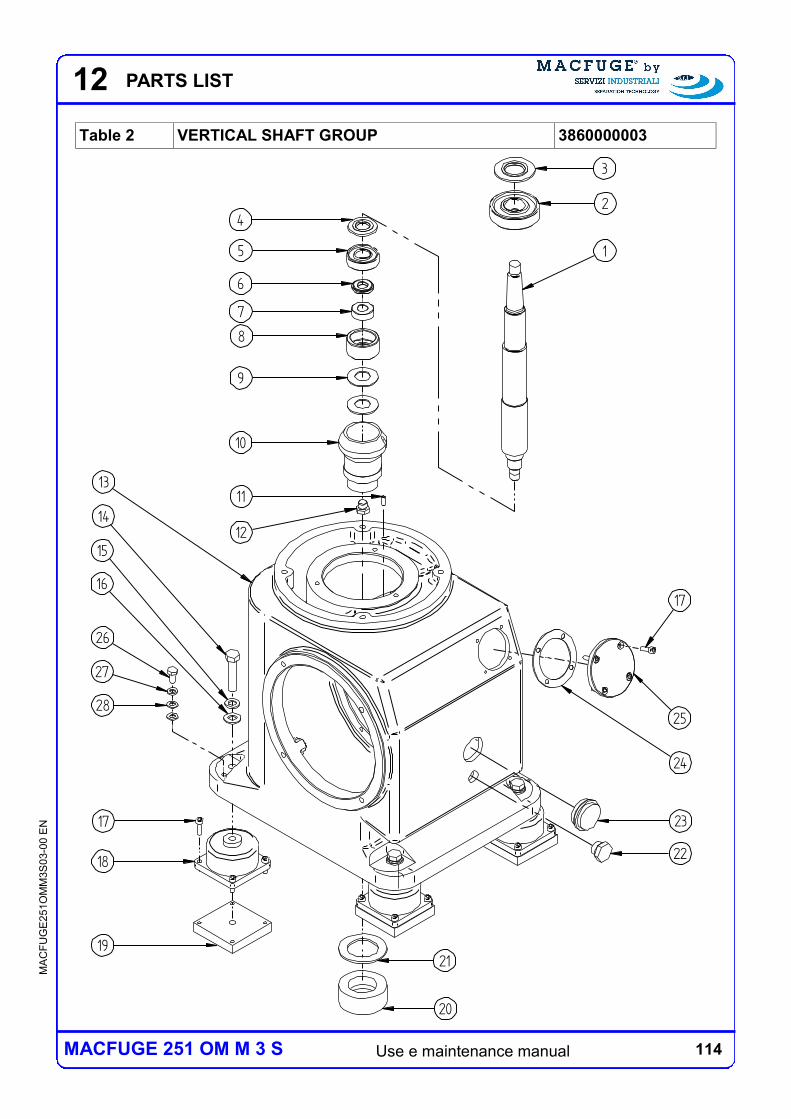
114 Use e maintenance manual
MA
CF
UG
E2
51O
MM
3S
03-0
0 E
N
MACFUGE 251 OM M 3 S
12 PARTS LIST
Table 2 VERTICAL SHAFT GROUP 3860000003
2
5
7
1822
9
2317
14
1
3
4
6
8
10
21
20
11
25
19
24
12
28
27
26
16
15
17
13
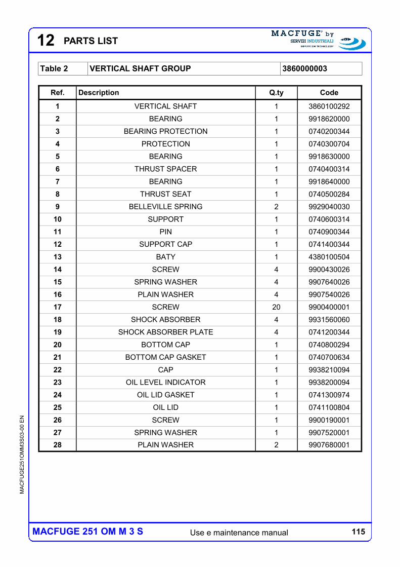
115 Use e maintenance manual
MA
CF
UG
E2
51O
MM
3S
03-0
0 E
N
MACFUGE 251 OM M 3 S
12 PARTS LIST
Table 2 VERTICAL SHAFT GROUP 3860000003
Ref. Description Q.ty Code
1 VERTICAL SHAFT 1 3860100292
2 BEARING 1 9918620000
3 BEARING PROTECTION 1 0740200344
4 PROTECTION 1 0740300704
5 BEARING 1 9918630000
6 THRUST SPACER 1 0740400314
7 BEARING 1 9918640000
8 THRUST SEAT 1 0740500284
9 BELLEVILLE SPRING 2 9929040030
10 SUPPORT 1 0740600314
11 PIN 1 0740900344
12 SUPPORT CAP 1 0741400344
13 BATY 1 4380100504
14 SCREW 4 9900430026
15 SPRING WASHER 4 9907640026
16 PLAIN WASHER 4 9907540026
17 SCREW 20 9900400001
18 SHOCK ABSORBER 4 9931560060
19 SHOCK ABSORBER PLATE 4 0741200344
20 BOTTOM CAP 1 0740800294
21 BOTTOM CAP GASKET 1 0740700634
22 CAP 1 9938210094
23 OIL LEVEL INDICATOR 1 9938200094
24 OIL LID GASKET 1 0741300974
25 OIL LID 1 0741100804
26 SCREW 1 9900190001
27 SPRING WASHER 1 9907520001
28 PLAIN WASHER 2 9907680001
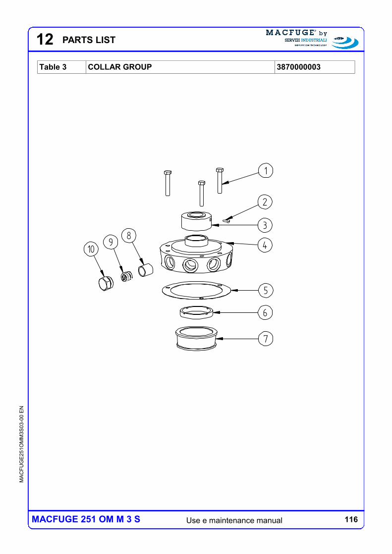
116 Use e maintenance manual
MA
CF
UG
E2
51O
MM
3S
03-0
0 E
N
MACFUGE 251 OM M 3 S
12 PARTS LIST
Table 3 COLLAR GROUP 3870000003
1
3
5
6
7
109
84
2
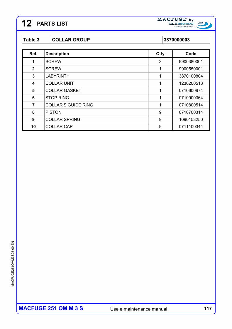
117 Use e maintenance manual
MA
CF
UG
E2
51O
MM
3S
03-0
0 E
N
MACFUGE 251 OM M 3 S
12 PARTS LIST
Table 3 COLLAR GROUP 3870000003
Ref. Description Q.ty Code
1 SCREW 3 9900380001
2 SCREW 1 9900550001
3 LABYRINTH 1 3870100804
4 COLLAR UNIT 1 1230200513
5 COLLAR GASKET 1 0710600974
6 STOP RING 1 0710900364
7 COLLAR’S GUIDE RING 1 0710800514
8 PISTON 9 0710700314
9 COLLAR SPRING 9 1090153250
10 COLLAR CAP 9 0711100344
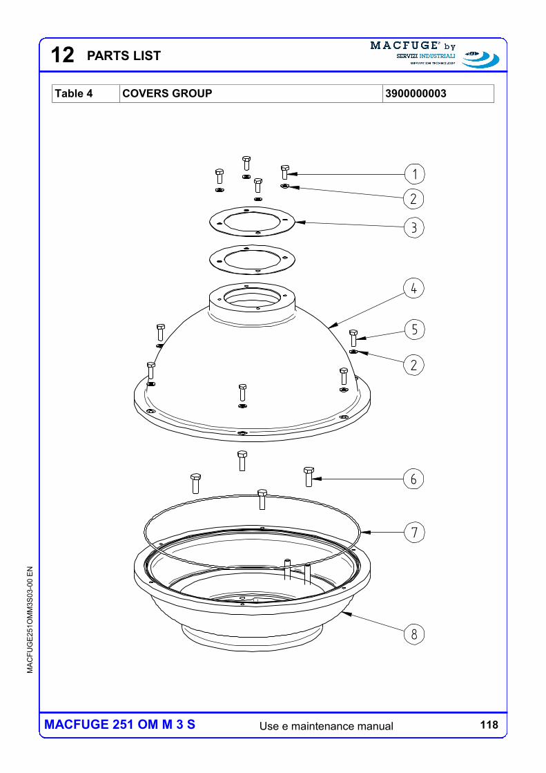
118 Use e maintenance manual
MA
CF
UG
E2
51O
MM
3S
03-0
0 E
N
MACFUGE 251 OM M 3 S
12 PARTS LIST
Table 4 COVERS GROUP 3900000003
1
2
3
5
2
4
6
7
8
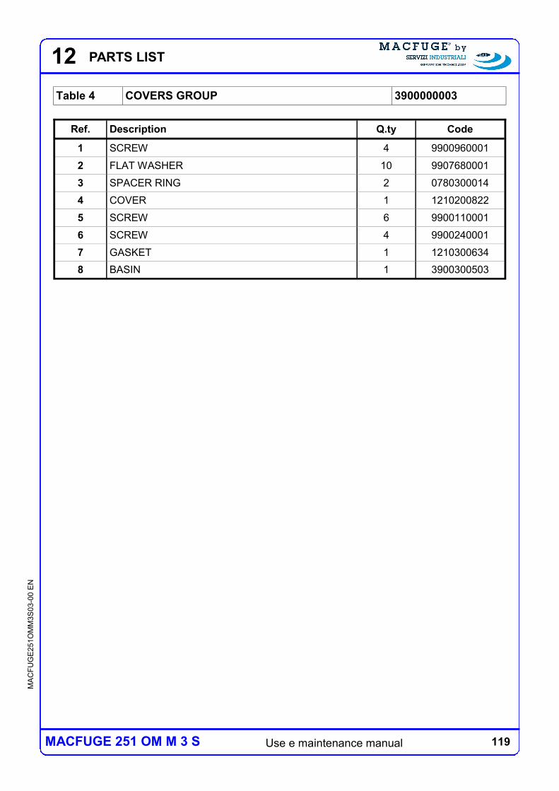
119 Use e maintenance manual
MA
CF
UG
E2
51O
MM
3S
03-0
0 E
N
MACFUGE 251 OM M 3 S
12 PARTS LIST
Table 4 COVERS GROUP 3900000003
Ref. Description Q.ty Code
1 SCREW 4 9900960001
2 FLAT WASHER 10 9907680001
3 SPACER RING 2 0780300014
4 COVER 1 1210200822
5 SCREW 6 9900110001
6 SCREW 4 9900240001
7 GASKET 1 1210300634
8 BASIN 1 3900300503
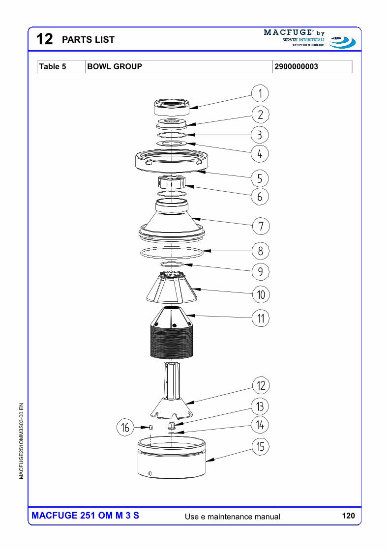
120 Use e maintenance manual
MA
CF
UG
E2
51O
MM
3S
03-0
0 E
N
MACFUGE 251 OM M 3 S
12 PARTS LIST
Table 5 BOWL GROUP 2900000003
16
4
2
6
9
14
3
1
8
7
5
10
11
12
13
15
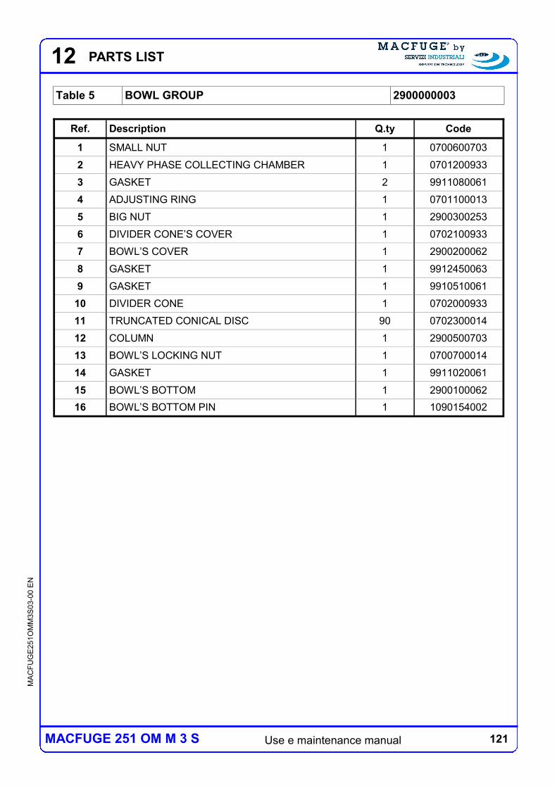
121 Use e maintenance manual
MA
CF
UG
E2
51O
MM
3S
03-0
0 E
N
MACFUGE 251 OM M 3 S
12 PARTS LIST
Table 5 BOWL GROUP 2900000003
Ref. Description Q.ty Code
1 SMALL NUT 1 0700600703
2 HEAVY PHASE COLLECTING CHAMBER 1 0701200933
3 GASKET 2 9911080061
4 ADJUSTING RING 1 0701100013
5 BIG NUT 1 2900300253
6 DIVIDER CONE’S COVER 1 0702100933
7 BOWL’S COVER 1 2900200062
8 GASKET 1 9912450063
9 GASKET 1 9910510061
10 DIVIDER CONE 1 0702000933
11 TRUNCATED CONICAL DISC 90 0702300014
12 COLUMN 1 2900500703
13 BOWL’S LOCKING NUT 1 0700700014
14 GASKET 1 9911020061
15 BOWL’S BOTTOM 1 2900100062
16 BOWL’S BOTTOM PIN 1 1090154002
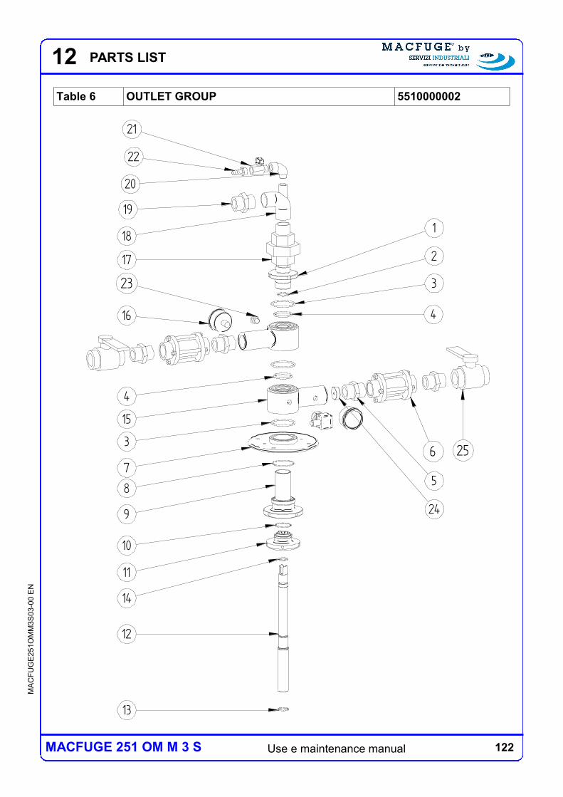
122 Use e maintenance manual
MA
CF
UG
E2
51O
MM
3S
03-0
0 E
N
MACFUGE 251 OM M 3 S
12 PARTS LIST
Table 6 OUTLET GROUP 5510000002
4
15
3
7
8
9
1
2
3
4
10
12
11
13
14
16
17
18
20
21
22
23
19
24
5
6 25
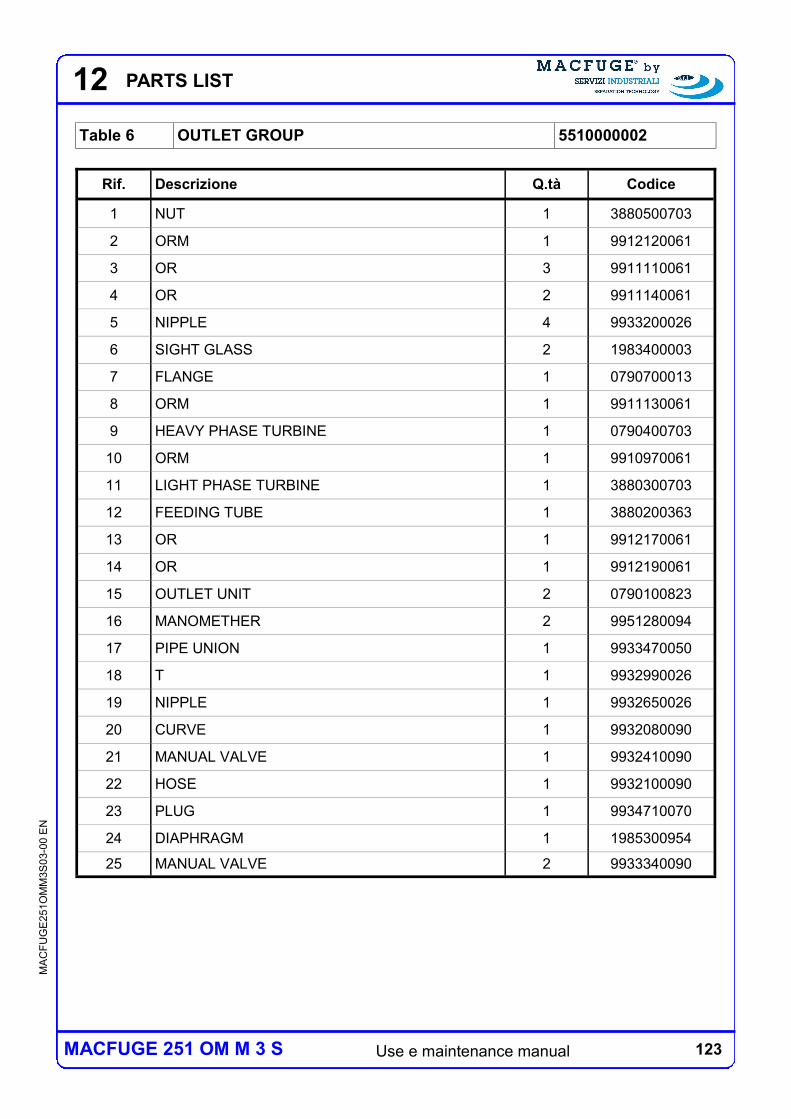
123 Use e maintenance manual
MA
CF
UG
E2
51O
MM
3S
03-0
0 E
N
MACFUGE 251 OM M 3 S
12 PARTS LIST
Table 6 OUTLET GROUP 5510000002
Rif. Descrizione Q.tà Codice
1 NUT 1 3880500703
2 ORM 1 9912120061
3 OR 3 9911110061
4 OR 2 9911140061
5 NIPPLE 4 9933200026
6 SIGHT GLASS 2 1983400003
7 FLANGE 1 0790700013
8 ORM 1 9911130061
9 HEAVY PHASE TURBINE 1 0790400703
10 ORM 1 9910970061
11 LIGHT PHASE TURBINE 1 3880300703
12 FEEDING TUBE 1 3880200363
13 OR 1 9912170061
14 OR 1 9912190061
15 OUTLET UNIT 2 0790100823
16 MANOMETHER 2 9951280094
17 PIPE UNION 1 9933470050
18 T 1 9932990026
19 NIPPLE 1 9932650026
20 CURVE 1 9932080090
21 MANUAL VALVE 1 9932410090
22 HOSE 1 9932100090
23 PLUG 1 9934710070
24 DIAPHRAGM 1 1985300954
25 MANUAL VALVE 2 9933340090
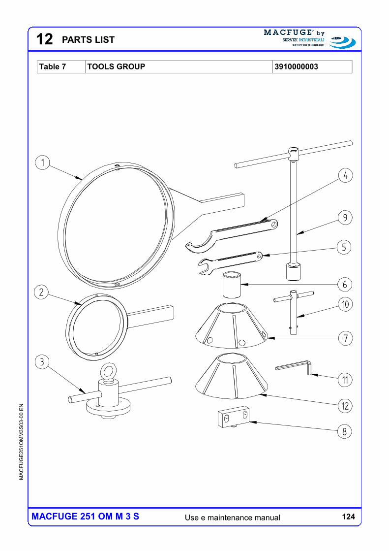
124 Use e maintenance manual
MA
CF
UG
E2
51O
MM
3S
03-0
0 E
N
MACFUGE 251 OM M 3 S
12 PARTS LIST
Table 7 TOOLS GROUP 3910000003
4
6
3
7
9
8
5
1
210
11
12
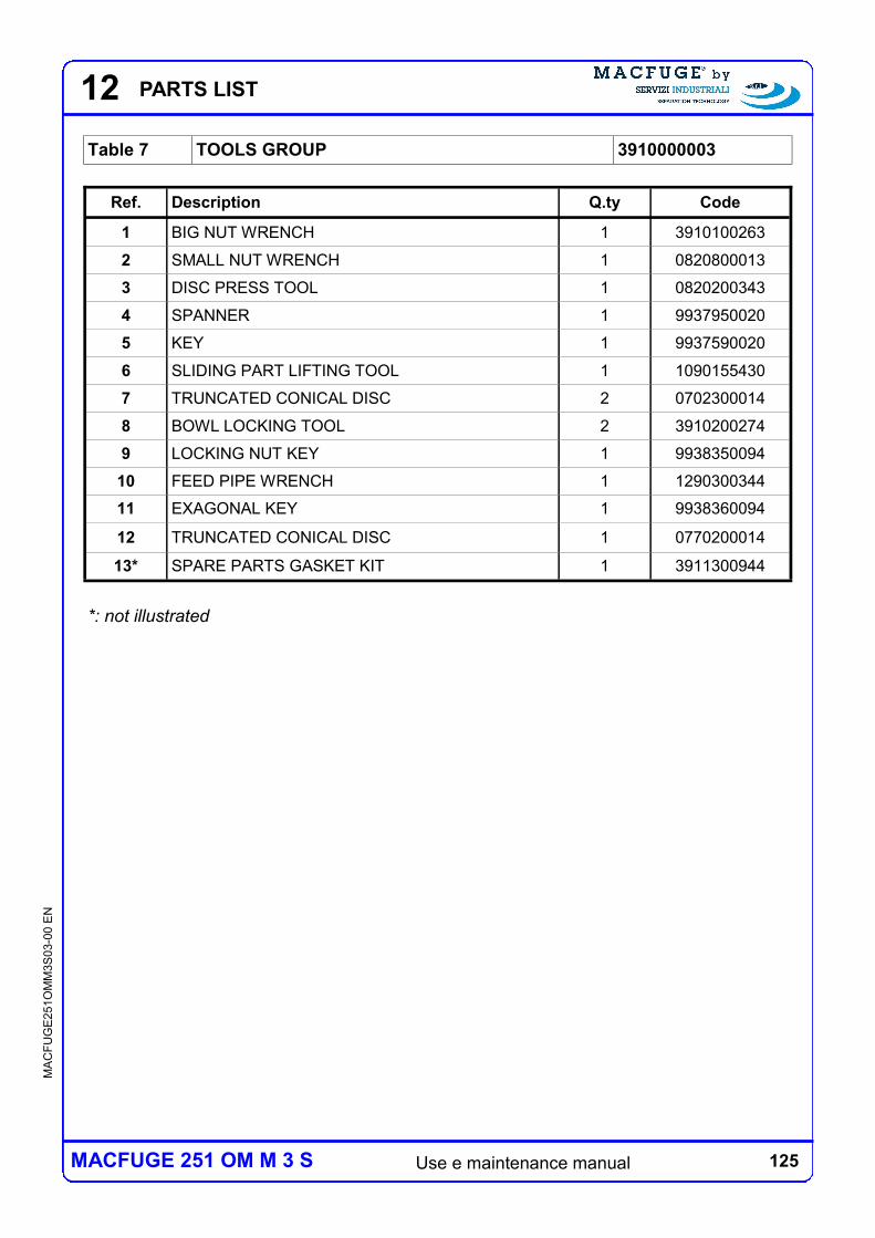
125 Use e maintenance manual
MA
CF
UG
E2
51O
MM
3S
03-0
0 E
N
MACFUGE 251 OM M 3 S
12 PARTS LIST
Ref. Description Q.ty Code
1 BIG NUT WRENCH 1 3910100263
2 SMALL NUT WRENCH 1 0820800013
3 DISC PRESS TOOL 1 0820200343
4 SPANNER 1 9937950020
5 KEY 1 9937590020
6 SLIDING PART LIFTING TOOL 1 1090155430
7 TRUNCATED CONICAL DISC 2 0702300014
8 BOWL LOCKING TOOL 2 3910200274
9 LOCKING NUT KEY 1 9938350094
10 FEED PIPE WRENCH 1 1290300344
11 EXAGONAL KEY 1 9938360094
12 TRUNCATED CONICAL DISC 1 0770200014
13* SPARE PARTS GASKET KIT 1 3911300944
Table 7 TOOLS GROUP 3910000003
*: not illustrated
126 Use e maintenance manual
MA
CF
UG
E2
51O
MM
3S
03-0
0 E
N
MACFUGE 251 OM M 3 S
12 PARTS LIST
127 Use e maintenance manual
MA
CF
UG
E2
51O
MM
3S
03-0
0 E
N
MACFUGE 251 OM M 3 S
13 SPARE PARTS
13 SPARE PARTS
13.1 SPARE PARTS PRESCRIBED
With reference to the terms and timescales already described in Chapter 10, the spare
parts required for the proper conduct of the centrifuge covered by this manual are as
follows:
spare parts gasket kit: parts which may be necessary during maintenance and
inspections required according to the schedule described above and must be kept
available, a number of these spare parts is supplied as a kit, the number of these parts
has code 3911300944;
spare parts 1 year of work meccanical kit: parts which may be necessary during
maintenance and inspections to be carried out at least once a year and must be kept
available, bearing replacement is required in every case regardless of the state in which
they are found at the time of maintenance, the series of these parts has code
3911301944.
128 Use e maintenance manual
MA
CF
UG
E2
51O
MM
3S
03-0
0 E
N
MACFUGE 251 OM M 3 S
13 SPARE PARTS
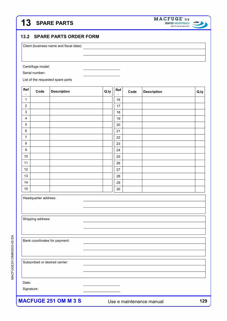
129 Use e maintenance manual
MA
CF
UG
E2
51O
MM
3S
03-0
0 E
N
MACFUGE 251 OM M 3 S
13 SPARE PARTS
13.2 SPARE PARTS ORDER FORM
Code Description Q.ty Ref.
16
17
18
19
20
21
22
23
24
25
26
27
28
29
30
Code Description Q.ty Ref.
1
2
3
4
5
6
7
8
9
10
11
12
13
14
15
Centrifuge model:
Serial number:
List of the requested spare parts
Subscribed or desired carrier:
Bank coordinates for payment:
Shipping address:
Headquarter address:
Client (business name and fiscal data):
Date:
Signature:

130 Use e maintenance manual
MA
CF
UG
E2
51O
MM
3S
03-0
0 E
N
MACFUGE 251 OM M 3 S
13 SPARE PARTS
131 Use e maintenance manual
MA
CF
UG
E2
51O
MM
3S
03-0
0 E
N
MACFUGE 251 OM M 3 S
14 VARIATIONS
14 VARIATIONS
Here following are described the variations eventually made to the centrifuge compared to
the standard configuration.
Note:
A copy of this form is recorded by Servizi Industriali S.r.l.

132 Use e maintenance manual
MA
CF
UG
E2
51O
MM
3S
03-0
0 E
N
MACFUGE 251 OM M 3 S
14 VARIATIONS
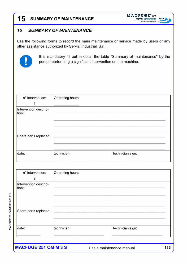
133 Use e maintenance manual
MA
CF
UG
E2
51O
MM
3S
03-0
0 E
N
MACFUGE 251 OM M 3 S
15 SUMMARY OF MAINTENANCE
15 SUMMARY OF MAINTENANCE
Use the following forms to record the main maintenance or service made by users or any
other assistance authorized by Servizi Industriali S.r.l.
It is mandatory fill out in detail the table "Summary of maintenance" by the
person performing a significant intervention on the machine.
n° intervention: Operating hours:
1 _____________
Intervention descrip-tion:
__________________________________________________________
__________________________________________________________
__________________________________________________________
__________________________________________________________
Spare parts replaced: __________________________________________________________
__________________________________________________________
__________________________________________________________
date: technician: technician sign:
____________ __________________________ __________________________
n° intervention: Operating hours:
2 _____________
Intervention descrip-tion:
__________________________________________________________
__________________________________________________________
__________________________________________________________
__________________________________________________________
Spare parts replaced: __________________________________________________________
__________________________________________________________
__________________________________________________________
date: technician: technician sign:
____________ __________________________ __________________________

134 Use e maintenance manual
MA
CF
UG
E2
51O
MM
3S
03-0
0 E
N
MACFUGE 251 OM M 3 S
15
n° intervention: Operating hours:
3 _____________
Intervention descrip-tion:
__________________________________________________________
__________________________________________________________
__________________________________________________________
__________________________________________________________
Spare parts replaced: __________________________________________________________
__________________________________________________________
__________________________________________________________
date: technician: technician sign:
____________ __________________________ __________________________
n° intervention: Operating hours:
4 _____________
Intervention descrip-tion:
__________________________________________________________
__________________________________________________________
__________________________________________________________
__________________________________________________________
Spare parts replaced: __________________________________________________________
__________________________________________________________
__________________________________________________________
date: technician: technician sign:
____________ __________________________ __________________________
n° intervention: Operating hours:
5 _____________
Intervention descrip-tion:
__________________________________________________________
__________________________________________________________
__________________________________________________________
__________________________________________________________
Spare parts replaced: __________________________________________________________
__________________________________________________________
__________________________________________________________
date: technician: technician sign:
____________ __________________________ __________________________
SUMMARY OF MAINTENANCE
135 Use e maintenance manual
MA
CF
UG
E2
51O
MM
3S
03-0
0 E
N
MACFUGE 251 OM M 3 S
15
n° intervention: Operating hours:
6 _____________
Intervention descrip-tion:
__________________________________________________________
__________________________________________________________
__________________________________________________________
__________________________________________________________
Spare parts replaced: __________________________________________________________
__________________________________________________________
__________________________________________________________
date: technician: technician sign:
____________ __________________________ __________________________
n° intervention: Operating hours:
7 _____________
Intervention descrip-tion:
__________________________________________________________
__________________________________________________________
__________________________________________________________
__________________________________________________________
Spare parts replaced: __________________________________________________________
__________________________________________________________
__________________________________________________________
date: technician: technician sign:
____________ __________________________ __________________________
n° intervention: Operating hours:
8 _____________
Intervention descrip-tion:
__________________________________________________________
__________________________________________________________
__________________________________________________________
__________________________________________________________
Spare parts replaced: __________________________________________________________
__________________________________________________________
__________________________________________________________
date: technician: technician sign:
____________ __________________________ __________________________
SUMMARY OF MAINTENANCE
136 Use e maintenance manual
MA
CF
UG
E2
51O
MM
3S
03-0
0 E
N
MACFUGE 251 OM M 3 S
15
n° intervention: Operating hours:
9 _____________
Intervention descrip-tion:
__________________________________________________________
__________________________________________________________
__________________________________________________________
__________________________________________________________
Spare parts replaced: __________________________________________________________
__________________________________________________________
__________________________________________________________
date: technician: technician sign:
____________ __________________________ __________________________
n° intervention: Operating hours:
10 _____________
Intervention descrip-tion:
__________________________________________________________
__________________________________________________________
__________________________________________________________
__________________________________________________________
Spare parts replaced: __________________________________________________________
__________________________________________________________
__________________________________________________________
date: technician: technician sign:
____________ __________________________ __________________________
n° intervention: Operating hours:
11 _____________
Intervention descrip-tion:
__________________________________________________________
__________________________________________________________
__________________________________________________________
__________________________________________________________
Spare parts replaced: __________________________________________________________
__________________________________________________________
__________________________________________________________
date: technician: technician sign:
____________ __________________________ __________________________
SUMMARY OF MAINTENANCE