Embed Size (px)
Citation preview
USE AND MAINTENANCE MANUAL
SIMPLA 50 B-BT SIMPLA 50 E
ED. 06-2011 EN
ORIGINAL
INSTRUCTIONS
Doc. 10026263
The descriptions contained in this document are not binding. The company therefore reserves the right to make any modifications at any time to elements, details, or accessory supply, as considered necessary for reasons of improvement or manufacturing/commercial requirements. The reproduction, even partial, of the text and drawings contained in this document is prohibited by law.
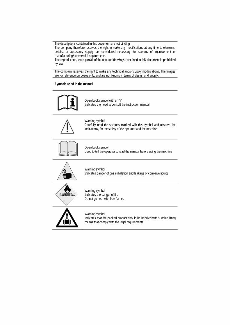
The company reserves the right to make any technical and/or supply modifications. The images are for reference purposes only, and are not binding in terms of design and supply. Symbols used in the manual
Open book symbol with an "i" Indicates the need to consult the instruction manual
Warning symbol Carefully read the sections marked with this symbol and observe the indications, for the safety of the operator and the machine
Open book symbol Used to tell the operator to read the manual before using the machine
Warning symbol Indicates danger of gas exhalation and leakage of corrosive liquids
Warning symbol Indicates the danger of fire Do not go near with free flames
Warning symbol Indicates that the packed product should be handled with suitable lifting means that comply with the legal requirements
3
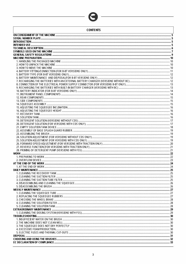
CONTENTS
ON CONSIGNMENT OF THE MACHINE..................................................................................................................................................................................... 5 SERIAL NUMBER PLATE............................................................................................................................................................................................................ 5 INTRODUCTION........................................................................................................................................................................................................................... 5 INTENDED USE............................................................................................................................................................................................................................ 5 TECHNICAL DESCRIPTION ........................................................................................................................................................................................................ 6 SYMBOLS USED ON THE MACHINE ......................................................................................................................................................................................... 7 GENERAL SAFETY REGULATIONS .......................................................................................................................................................................................... 9 MACHINE PREPARATION ........................................................................................................................................................................................................ 10
1. HANDLING THE PACKAGED MACHINE .......................................................................................................................................................................... 10 2. HOW TO UNPACK THE MACHINE................................................................................................................................................................................... 10 3. HOW TO MOVE THE MACHINE ....................................................................................................................................................................................... 10 4. BATTERY FITTING/CONNECTION (FOR B-BT VERSIONS ONLY)................................................................................................................................ 11 5. BATTERY TYPE (FOR B-BT VERSIONS ONLY).............................................................................................................................................................. 12 6. BATTERY MAINTENANCE AND DISPOSAL(FOR B-BT VERSIONS ONLY) ................................................................................................................. 12 7. RECHARGING THE BATTERIES WITH AN EXTERNAL BATTERY CHARGER (VERSIONS WITHOUT BC)............................................................... 12 8. CONNECTION OF THE ELECTRICAL POWER SUPPLY CONNECTOR (FOR VERSIONS B-BT ONLY)..................................................................... 13 9. RECHARGING THE BATTERIES WITH BUILT-IN BATTERY CHARGER (VERSIONS WITH BC) ................................................................................ 13 10. BATTERY INDICATOR (FOR B-BT VERSIONS ONLY) ................................................................................................................................................. 14 11. INSTRUMENT PANEL COMPONENTS .......................................................................................................................................................................... 14 12. REAR COMPONENTS..................................................................................................................................................................................................... 15 13. SIDE COMPONENTS ...................................................................................................................................................................................................... 15 14. SQUEEGEE ASSEMBLY................................................................................................................................................................................................. 15 15. ADJUSTING THE SQUEEGEE INCLINATION................................................................................................................................................................ 16 16. ADJUSTING THE SQUEEGEE HEIGHT ......................................................................................................................................................................... 16 17. RECOVERY TANK........................................................................................................................................................................................................... 16 18. SOLUTION TANK............................................................................................................................................................................................................. 16 19. DETERGENT SOLUTION (VERSIONS WITHOUT CDS) ............................................................................................................................................... 17 20. DETERGENT SOLUTION (FOR VERSIONS WITH CDS ONLY). .................................................................................................................................. 17 21. EMPTY SOLUTION TANK DEVICE................................................................................................................................................................................. 18 22. ASSEMBLY OF BASE SPLASH GUARD RUBBER. ....................................................................................................................................................... 19 23. ASSEMBLING THE BRUSH ............................................................................................................................................................................................ 19 24. SOLUTION ADJUSTMENT (FOR VERSIONS WITHOUT CDS ONLY).......................................................................................................................... 19 25. SOLUTION ADJUSTMENT (FOR VERSIONS WITH CDS ONLY) ................................................................................................................................. 19 26. FORWARD SPEED ADJUSTMENT (FOR VERSIONS WITH TRACTION ONLY) ......................................................................................................... 20 27. REVERSE FUNCTION (FOR VERSIONS WITH TRACTION ONLY) ............................................................................................................................. 21 28. PRIMING OF DETERGENT PUMP (VERSIONS WITH FSS) ......................................................................................................................................... 21
WORK ......................................................................................................................................................................................................................................... 22 1. PREPARING TO WORK .................................................................................................................................................................................................... 22 2. OVERFLOW DEVICE......................................................................................................................................................................................................... 23
AT THE END OF THE WORK .................................................................................................................................................................................................... 24 1. AT THE END OF WORK.................................................................................................................................................................................................... 24
DAILY MAINTENANCE .............................................................................................................................................................................................................. 25 1. CLEANING THE RECOVERY TANK ................................................................................................................................................................................. 25 2. CLEANING THE SUCTION FILTER .................................................................................................................................................................................. 25 3. CLEANING THE SUCTION TUBE FILTER........................................................................................................................................................................ 25 4. DISASSEMBLING AND CLEANING THE SQUEEGEE..................................................................................................................................................... 26 5. DISASSEMBLING THE BRUSH ........................................................................................................................................................................................ 26
WEEKLY MAINTENANCE ......................................................................................................................................................................................................... 27 1. CLEANING THE SQUEEGEE TUBE ................................................................................................................................................................................. 27 2. REPLACING THE SQUEEGEE RUBBERS....................................................................................................................................................................... 27 3. CHECKING THE WHEEL BRAKE ..................................................................................................................................................................................... 28 4. CLEANING THE SOLUTION FILTER ................................................................................................................................................................................ 28 5. CLEANING THE SOLUTION TANK................................................................................................................................................................................... 28
EXTRAORDINARY MAINTENANCE ......................................................................................................................................................................................... 29 1. CLEANING THE DOSING SYSTEM (VERSIONS WITH FSS).......................................................................................................................................... 29
TROUBLESHOOTING................................................................................................................................................................................................................ 30 1. INSUFFICIENT WATER ON THE BRUSH ........................................................................................................................................................................ 30 2. THE MACHINE DOES NOT CLEAN WELL ....................................................................................................................................................................... 30 3. THE SQUEEGEE DOES NOT DRY PERFECTLY ............................................................................................................................................................ 30 4. EXCESSIVE FOAM PRODUCTION................................................................................................................................................................................... 30 5. ELECTRIC FUSES AND THERMAL CUT-OUTS .............................................................................................................................................................. 30
DISPOSAL .................................................................................................................................................................................................................................. 31 CHOOSING AND USING THE BRUSHES................................................................................................................................................................................. 32 EC DECLARATION OF COMPLIANCE..................................................................................................................................................................................... 33

4
EC DECLARATION OF COMPLIANCE..................................................................................................................................................................................... 34
5
On consignment of the machine When the machine is delivered to the customer, an immediate check must be performed to ensure all the material mentioned in the shipping documents has been received, and also to check the machine has not been damaged during transportation. If this is the case, the carrier must ascertain the extent of the damage at once, informing our customer service office. It is only by prompt action of this type that the missing material can be obtained, and compensation for damage successfully claimed.
Introduction Simpla is a floor scrubbing machine which, by means of the mechanical action of the rotating brush and the chemical action of a water/detergent solution, can clean any type of flooring. As it advances, it also collects any removed dirt as well as the detergent solution not absorbed by the floor. The machine must only be used for this purpose. Even the best machines will only work well if used correctly and kept in good working order. We therefore suggest you read this instruction booklet carefully and read it again whenever difficulties arise while using the machine. If necessary, remember that our customer assistance service (organised in collaboration with our dealers) is always available for advice or direct intervention. Intended use The scrubbing machine is designed exclusively for the professional cleaning of surfaces and floors in industrial, commercial and public environments. The machine is only suitable for use in closed (or at least covered) places. The machine is not suitable for use in the rain, or under water jets. It is FORBIDDEN to use the machine in places with a potentially explosive atmosphere, for picking up dangerous dusts or inflammable liquids. In addition, it is not suitable as a means of transport for people or objects.
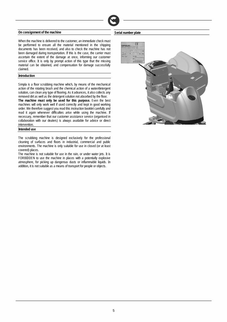
Serial number plate
6
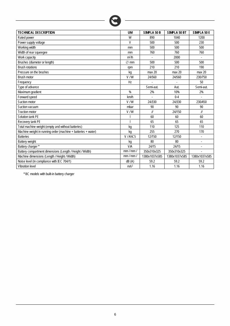
TECHNICAL DESCRIPTION UM SIMPLA 50 B SIMPLA 50 BT SIMPLA 50 E Rated power W 890 1040 1200 Power supply voltage V 500 500 230 Working width mm 500 500 500 Width of rear squeegee mm 760 760 760 Work capacity m2/h - 2000 - Brushes (diameter or length) mm 500 500 500 Brush rotations rpm 210 210 190 Pressure on the brushes kg max 20 max 20 max 20 Brush motor V / W 24/560 24/560 230/750 Frequency Hz - - 50 Type of advance Semi-aut. Aut. Semi-aut. Maximum gradient % 2% 10% 2%
Forward speed km/h - 0-4 - Suction motor V / W 24/330 24/330 230/450 Suction vacuum mbar 90 90 90 Traction motor V / W // 24/150 // Solution tank PE l 60 60 60 Recovery tank PE l 65 65 65 Total machine weight (empty and without batteries) kg 110 125 110 Machine weight in running order (machine + batteries + water) kg 255 270 170 Batteries V / AhC5 12/150 12/150 - Battery weight kg 80 80 - Battery charger * V/A 24/15 24/15 - Battery compartment dimensions (Length / Height / Width) mm / mm /
350x310x325 350x310x325 -
Machine dimensions (Length / Height / Width) mm / mm /
1380x1037x585 1380x1037x585 1380x1037x585 Noise level (in compliance with IEC 704/1) dB (A) 59.2 59.2 59.2 Vibration level m/s2 1.16 1.16 1.16
* BC models with built-in battery charger
7
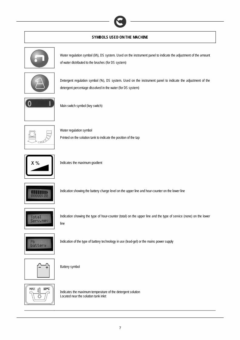
SYMBOLS USED ON THE MACHINE
Water regulation symbol (l/h), DS system. Used on the instrument panel to indicate the adjustment of the amount
of water distributed to the brushes (for DS system)
Detergent regulation symbol (%), DS system. Used on the instrument panel to indicate the adjustment of the
detergent percentage dissolved in the water (for DS system)
Main switch symbol (key switch)
Water regulation symbol
Printed on the solution tank to indicate the position of the tap
Indicates the maximum gradient
Indication showing the battery charge level on the upper line and hour-counter on the lower line
Indication showing the type of hour-counter (total) on the upper line and the type of service (none) on the lower
line
Indication of the type of battery technology in use (lead-gel) or the mains power supply
Battery symbol
Indicates the maximum temperature of the detergent solution Located near the solution tank inlet
8
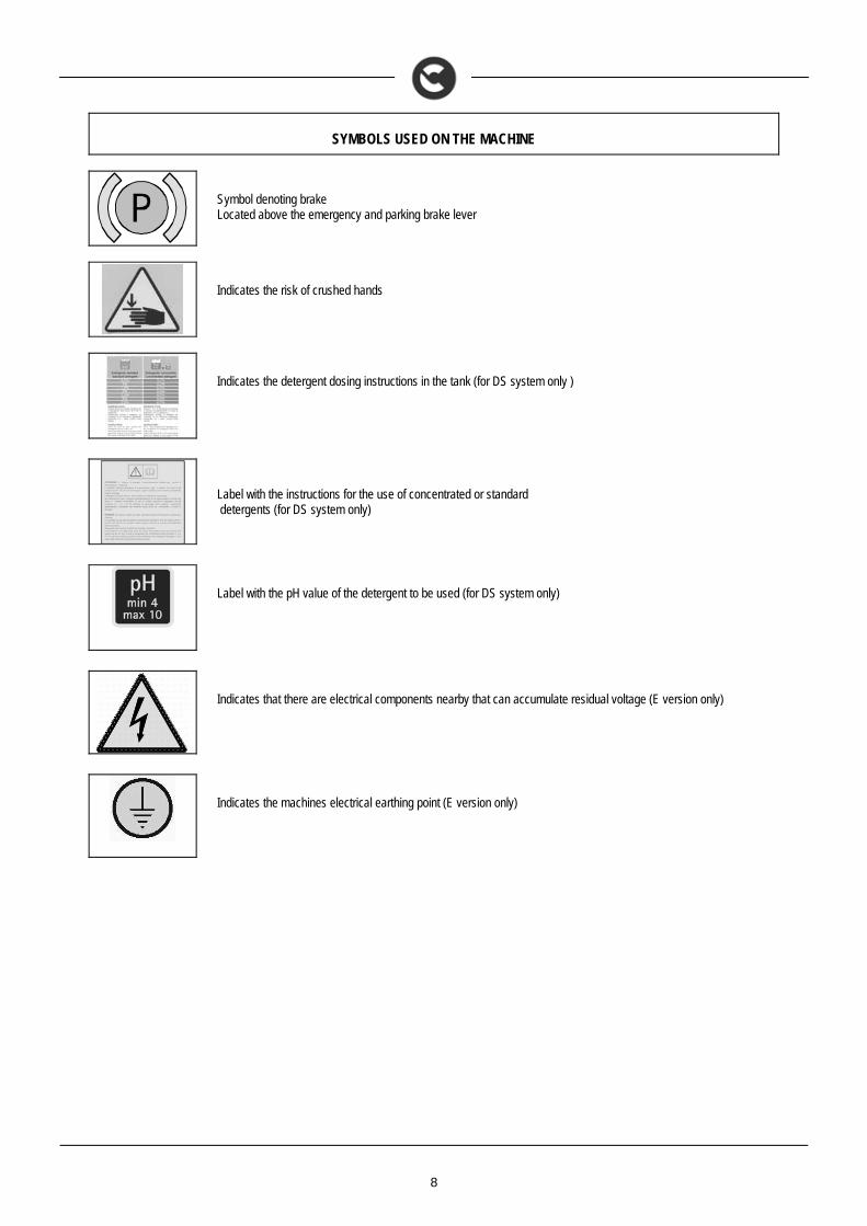
SYMBOLS USED ON THE MACHINE
Symbol denoting brake Located above the emergency and parking brake lever
Indicates the risk of crushed hands
Indicates the detergent dosing instructions in the tank (for DS system only )
Label with the instructions for the use of concentrated or standard detergents (for DS system only)
Label with the pH value of the detergent to be used (for DS system only)
Indicates that there are electrical components nearby that can accumulate residual voltage (E version only)
Indicates the machines electrical earthing point (E version only)
9
GENERAL SAFETY REGULATIONS
The regulations below must be carefully followed in order to avoid harm to the operator and damage to the machine. WARNING:
Read the labels on the machine carefully. Do not cover them for any reason and replace them immediately if they become damaged. The machine must be exclusively used by authorised, trained personnel. The machine is designed for dry use only. Do not use the machine on surfaces with an inclination greater than the one shown on the plate. The machine is not suitable for cleaning rough or uneven floors. Do not use the machine on slopes. Avoid damaging the power supply cable by crushing or bending it, or applying stress. If the power supply cable of the battery charger is damaged, contact an Authorised service centre immediately. Do not let the power cable come into contact with the rotating brush. In the event of danger, quickly intervene on the handle located on the battery connector. For all maintenance interventions, switch off the machine and disconnect the battery connector and/or the power supply cable. Children must be supervised to ensure they do not play with the device. During the working of the machine, pay attention to other people and especially to children. Only use the brushes supplied with the machine, or those specified in the "CHOOSING AND USING THE BRUSHES" paragraph of
the instruction manual. The use of other brushes could compromise safety levels. ATTENTION:
The machine is not suitable for use by children and persons with reduced physical, mental and sensory capabilities, or people who lack experience and knowledge.
The machine must not be used or stored outdoors, in damp conditions or directly exposed to rain. The storage temperature must be between -25C and +55C; do not store outdoors in damp conditions. Conditions of use: room temperature between 0°C and 40°C with relative humidity between 30 and 95% The socket for the machine's power cable (electric version) or for the battery charger power cable (battery version) must be correctly
earthed. Adapt the speed to the adhesion conditions. Do not use the machine as a means of transport. The machine does not cause harmful vibrations. Do not use the machine in an explosive atmosphere. Do not vacuum inflammable liquids. Do not use the device to collect dangerous powders. Do not mix different types of detergent as this may produce harmful gases. The machine is not suitable for cleaning carpets. Do not place any liquid containers on the machine. Avoid working with the brushes when the machine is standing still, so as not to damage the floor. In the event of a fire, use a powder extinguisher. Do not use water. Do not knock against shelving or scaffolding, where there is a danger of falling objects. The operator must always be equipped with
the appropriate safety devices (gloves, shoes, helmet, goggles, etc.). The machine is designed to simultaneously carry out the washing and drying operations. Different operations should only be carried
out in areas where the passage of unauthorised persons is prohibited. Signal the presence of damp floors with suitable signs. If the machine does not work properly, check this is not caused by failure to carry out routine maintenance. Otherwise, ask for
intervention of the authorised technical assistance centre. If you need to replace any components, request the ORIGINAL spare parts from an Authorised dealer and/or Retailer. Restore all electrical connections after any maintenance interventions. Before using the machine, check that all the hatches and covers are positioned as shown in this Use and Maintenance Manual. Do not remove any protection devices which require the use of tools in order to be removed. Do not wash the machine with direct water jets or with pressurised water, nor with corrosive substances. To prevent scaling in the solution tank filter, do not fill the tank with detergent solution many hours before using the machine. Do not use acid or basic solutions that could damage the machine and/or harm people. Have the machine checked by an authorised technical assistance centre every year. When disposing of consumption materials, comply with currently effective laws and regulations. When your machine has reached the end of its long working life, dispose of the materials it contains (especially oils, batteries and
electronic components) in an appropriate manner, taking into account that the machine itself was constructed using 100% recyclable materials.
The batteries must be removed from the machine before its disposal. The batteries must be disposed of in a safe manner, fully observing the laws and regulations in force.
10
MACHINE PREPARATION
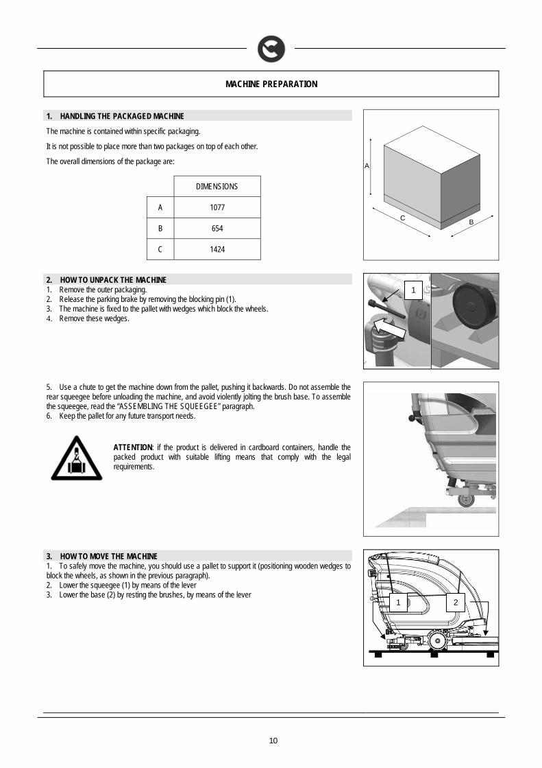
1. HANDLING THE PACKAGED MACHINE
The machine is contained within specific packaging.
It is not possible to place more than two packages on top of each other.
The overall dimensions of the package are:
DIMENSIONS
A 1077
B 654
C 1424
A
CB
2. HOW TO UNPACK THE MACHINE 1. Remove the outer packaging. 2. Release the parking brake by removing the blocking pin (1). 3. The machine is fixed to the pallet with wedges which block the wheels. 4. Remove these wedges.
5. Use a chute to get the machine down from the pallet, pushing it backwards. Do not assemble the rear squeegee before unloading the machine, and avoid violently jolting the brush base. To assemble the squeegee, read the “ASSEMBLING THE SQUEEGEE” paragraph. 6. Keep the pallet for any future transport needs.
ATTENTION: if the product is delivered in cardboard containers, handle the packed product with suitable lifting means that comply with the legal requirements.
3. HOW TO MOVE THE MACHINE 1. To safely move the machine, you should use a pallet to support it (positioning wooden wedges to block the wheels, as shown in the previous paragraph). 2. Lower the squeegee (1) by means of the lever 3. Lower the base (2) by resting the brushes, by means of the lever
1
1 2
11
MACHINE PREPARATION
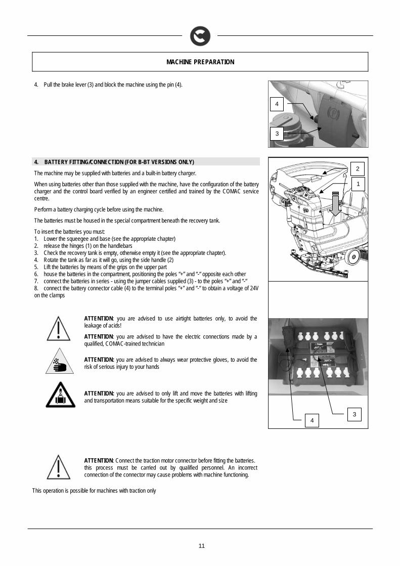
4. Pull the brake lever (3) and block the machine using the pin (4).
4. BATTERY FITTING/CONNECTION (FOR B-BT VERSIONS ONLY)
The machine may be supplied with batteries and a built-in battery charger.
When using batteries other than those supplied with the machine, have the configuration of the battery charger and the control board verified by an engineer certified and trained by the COMAC service centre.
Perform a battery charging cycle before using the machine.
The batteries must be housed in the special compartment beneath the recovery tank.
To insert the batteries you must: 1. Lower the squeegee and base (see the appropriate chapter) 2. release the hinges (1) on the handlebars 3. Check the recovery tank is empty, otherwise empty it (see the appropriate chapter). 4. Rotate the tank as far as it will go, using the side handle (2) 5. Lift the batteries by means of the grips on the upper part 6. house the batteries in the compartment, positioning the poles “+” and “-“ opposite each other 7. connect the batteries in series - using the jumper cables supplied (3) - to the poles “+” and “-“ 8. connect the battery connector cable (4) to the terminal poles “+” and “-“ to obtain a voltage of 24V on the clamps
ATTENTION: you are advised to use airtight batteries only, to avoid the leakage of acids!
ATTENTION: you are advised to have the electric connections made by a qualified, COMAC-trained technician
ATTENTION: you are advised to always wear protective gloves, to avoid the risk of serious injury to your hands
ATTENTION: you are advised to only lift and move the batteries with lifting and transportation means suitable for the specific weight and size
ATTENTION: Connect the traction motor connector before fitting the batteries. this process must be carried out by qualified personnel. An incorrect connection of the connector may cause problems with machine functioning.
This operation is possible for machines with traction only
1
2
3 4
3
4
12
MACHINE PREPARATION
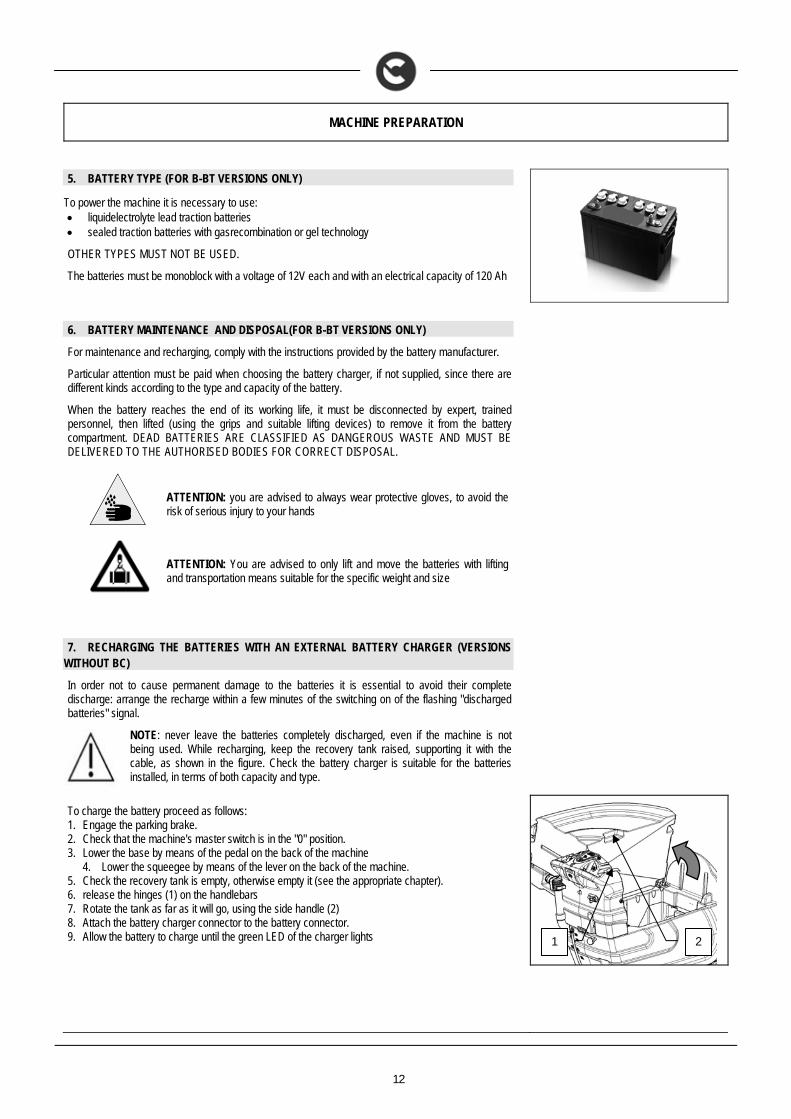
5. BATTERY TYPE (FOR B-BT VERSIONS ONLY)
To power the machine it is necessary to use: liquidelectrolyte lead traction batteries sealed traction batteries with gasrecombination or gel technology
OTHER TYPES MUST NOT BE USED.
The batteries must be monoblock with a voltage of 12V each and with an electrical capacity of 120 Ah
6. BATTERY MAINTENANCE AND DISPOSAL(FOR B-BT VERSIONS ONLY)
For maintenance and recharging, comply with the instructions provided by the battery manufacturer.
Particular attention must be paid when choosing the battery charger, if not supplied, since there are different kinds according to the type and capacity of the battery.
When the battery reaches the end of its working life, it must be disconnected by expert, trained personnel, then lifted (using the grips and suitable lifting devices) to remove it from the battery compartment. DEAD BATTERIES ARE CLASSIFIED AS DANGEROUS WASTE AND MUST BE DELIVERED TO THE AUTHORISED BODIES FOR CORRECT DISPOSAL.
ATTENTION: you are advised to always wear protective gloves, to avoid the risk of serious injury to your hands
ATTENTION: You are advised to only lift and move the batteries with lifting and transportation means suitable for the specific weight and size
7. RECHARGING THE BATTERIES WITH AN EXTERNAL BATTERY CHARGER (VERSIONS
WITHOUT BC)
In order not to cause permanent damage to the batteries it is essential to avoid their complete discharge: arrange the recharge within a few minutes of the switching on of the flashing "discharged batteries" signal.
NOTE: never leave the batteries completely discharged, even if the machine is not being used. While recharging, keep the recovery tank raised, supporting it with the cable, as shown in the figure. Check the battery charger is suitable for the batteries installed, in terms of both capacity and type.
To charge the battery proceed as follows: 1. Engage the parking brake. 2. Check that the machine's master switch is in the "0" position. 3. Lower the base by means of the pedal on the back of the machine
4. Lower the squeegee by means of the lever on the back of the machine. 5. Check the recovery tank is empty, otherwise empty it (see the appropriate chapter). 6. release the hinges (1) on the handlebars 7. Rotate the tank as far as it will go, using the side handle (2) 8. Attach the battery charger connector to the battery connector. 9. Allow the battery to charge until the green LED of the charger lights
2 1
13
MACHINE PREPARATION
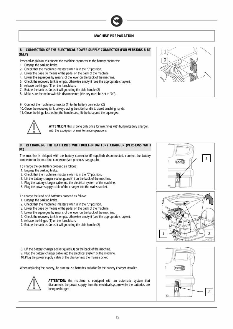
8. CONNECTION OF THE ELECTRICAL POWER SUPPLY CONNECTOR (FOR VERSIONS B-BT
ONLY)
Proceed as follows to connect the machine connector to the battery connector: 1. Engage the parking brake. 2. Check that the machine's master switch is in the "0" position. 3. Lower the base by means of the pedal on the back of the machine 4. Lower the squeegee by means of the lever on the back of the machine. 5. Check the recovery tank is empty, otherwise empty it (see the appropriate chapter). 6. release the hinges (1) on the handlebars 7. Rotate the tank as far as it will go, using the side handle (2) 8. Make sure the main switch is disconnected (the key must be set to "0 ").
2
1
9. Connect the machine connector (1) to the battery connector (2) 10. Close the recovery tank, always using the side handle to avoid crushing hands. 11. Close the hinge located on the handlebars, lift the base and the squeegee.
ATTENTION: this is done only once for machines with built-in battery charger, with the exception of maintenance operations
9. RECHARGING THE BATTERIES WITH BUILT-IN BATTERY CHARGER (VERSIONS WITH BC)
The machine is shipped with the battery connector (if supplied) disconnected, connect the battery connector to the machine connector (see previous paragraph).
To charge the gel battery proceed as follows: 1. Engage the parking brake. 2. Check that the machine's master switch is in the "0" position. 3. Lift the battery charger socket guard (1) on the back of the machine. 4. Plug the battery charger cable into the electrical system of the machine. 5. Plug the power supply cable of the charger into the mains socket.
To charge the lead acid batteries proceed as follows: 1. Engage the parking brake. 2. Check that the machine's master switch is in the "0" position. 3. Lower the base by means of the pedal on the back of the machine 4. Lower the squeegee by means of the lever on the back of the machine. 5. Check the recovery tank is empty, otherwise empty it (see the appropriate chapter). 6. release the hinges (1) on the handlebars 7. Rotate the tank as far as it will go, using the side handle (2)
8. Lift the battery charger socket guard (3) on the back of the machine. 9. Plug the battery charger cable into the electrical system of the machine. 10. Plug the power supply cable of the charger into the mains socket.
When replacing the battery, be sure to use batteries suitable for the battery charger installed.
ATTENTION: the machine is equipped with an automatic system that disconnects the power supply from the electrical system while the batteries are being recharged
1
2 1
3
14
MACHINE PREPARATION
ATTENTION: in order not to cause permanent damage to the batteries it is essential to avoid their complete discharge: arrange the recharge within a few minutes of the switching on of the flashing "discharged batteries" signal
ATTENTION: never leave the batteries completely discharged, even if the machine is not being used
ATTENTION: for the daily recharging of the batteries, you must fully respect the indications provided by the manufacturer or retailer. All installation and maintenance operations must be carried out by expert personnel, trained at the COMAC assistance centre
WARNING Make sure that the battery charger green LED is on before using the machine again
ATTENTION: danger of exhalation of gas and leakage of corrosive liquids
ATTENTION: danger of fire: do not go near with free flames
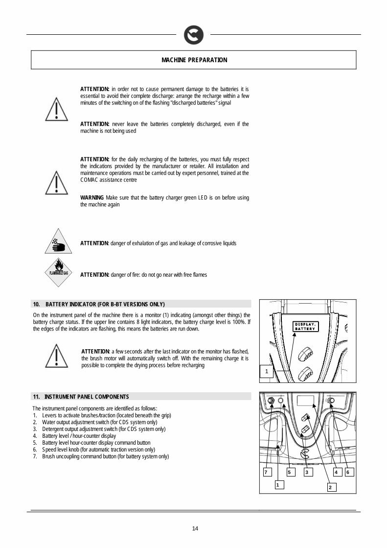
10. BATTERY INDICATOR (FOR B-BT VERSIONS ONLY)
On the instrument panel of the machine there is a monitor (1) indicating (amongst other things) the battery charge status. If the upper line contains 8 light indicators, the battery charge level is 100%. If the edges of the indicators are flashing, this means the batteries are run down.
ATTENTION: a few seconds after the last indicator on the monitor has flashed, the brush motor will automatically switch off. With the remaining charge it is possible to complete the drying process before recharging
11. INSTRUMENT PANEL COMPONENTS
The instrument panel components are identified as follows: 1. Levers to activate brushes/traction (located beneath the grip) 2. Water output adjustment switch (for CDS system only) 3. Detergent output adjustment switch (for CDS system only) 4. Battery level / hour-counter display 5. Battery level hour-counter display command button 6. Speed level knob (for automatic traction version only) 7. Brush uncoupling command button (for battery system only)
1
5
1
3
2
6 4 7
15
MACHINE PREPARATION
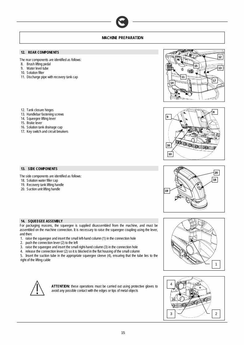
12. REAR COMPONENTS
The rear components are identified as follows: 8. Brush lifting pedal 9. Water level tube 10. Solution filter 11. Discharge pipe with recovery tank cap
12. Tank closure hinges 13. Handlebar fastening screws 14. Squeegee lifting lever 15. Brake lever 16. Solution tank drainage cap 17. Key switch and circuit breakers
13. SIDE COMPONENTS
The side components are identified as follows: 18. Solution water filler cap 19. Recovery tank lifting handle 20. Suction unit lifting handle
14. SQUEEGEE ASSEMBLY
For packaging reasons, the squeegee is supplied disassembled from the machine, and must be assembled on the machine connection. It is necessary to raise the squeegee coupling using the lever, and then: 1. raise the squeegee and insert the small left-hand column (1) in the connection hole 2. push the connection lever (2) to the left 3. raise the squeegee and insert the small right-hand column (3) in the connection hole 4. release the connection lever (2) so it is blocked in the flat housing of the small column 5. Insert the suction tube in the appropriate squeegee sleeve (4), ensuring that the tube lies to the right of the lifting cable
ATTENTION: these operations must be carried out using protective gloves to avoid any possible contact with the edges or tips of metal objects
10
11
12
13
14
15
17
16
8
9
20
19
18
1
2 3
4
16
MACHINE PREPARATION
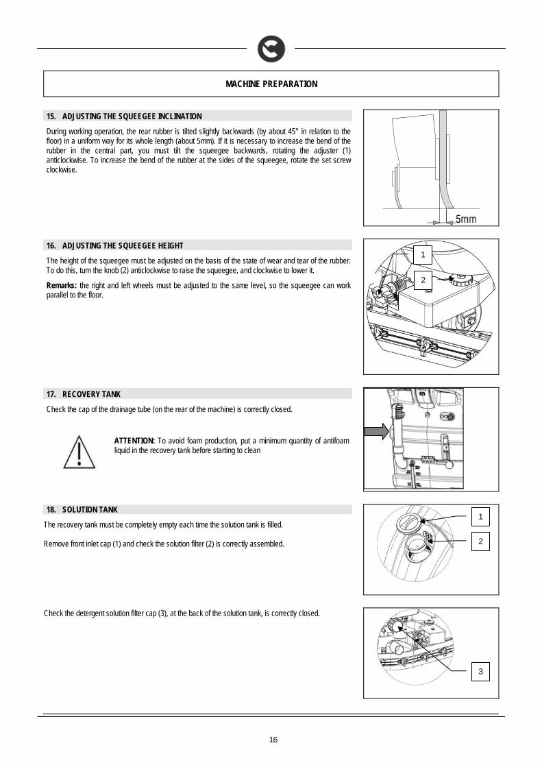
15. ADJUSTING THE SQUEEGEE INCLINATION
During working operation, the rear rubber is tilted slightly backwards (by about 45° in relation to the floor) in a uniform way for its whole length (about 5mm). If it is necessary to increase the bend of the rubber in the central part, you must tilt the squeegee backwards, rotating the adjuster (1) anticlockwise. To increase the bend of the rubber at the sides of the squeegee, rotate the set screw clockwise.
16. ADJUSTING THE SQUEEGEE HEIGHT
The height of the squeegee must be adjusted on the basis of the state of wear and tear of the rubber. To do this, turn the knob (2) anticlockwise to raise the squeegee, and clockwise to lower it.
Remarks: the right and left wheels must be adjusted to the same level, so the squeegee can work parallel to the floor.
17. RECOVERY TANK
Check the cap of the drainage tube (on the rear of the machine) is correctly closed.
ATTENTION: To avoid foam production, put a minimum quantity of antifoam liquid in the recovery tank before starting to clean
18. SOLUTION TANK
The recovery tank must be completely empty each time the solution tank is filled. Remove front inlet cap (1) and check the solution filter (2) is correctly assembled.
Check the detergent solution filter cap (3), at the back of the solution tank, is correctly closed.
2
1
1
2
3
17
MACHINE PREPARATION
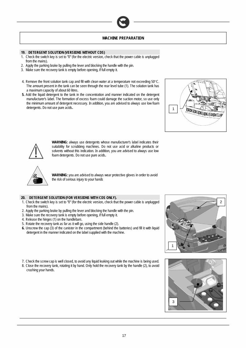
19. DETERGENT SOLUTION (VERSIONS WITHOUT CDS) 1. Check the switch key is set to "0" (for the electric version, check that the power cable is unplugged
from the mains). 2. Apply the parking brake by pulling the lever and blocking the handle with the pin. 3. Make sure the recovery tank is empty before opening, if full empty it.
4. Remove the front solution tank cap and fill with clean water at a temperature not exceeding 50C.
The amount present in the tank can be seen through the rear level tube (1). The solution tank has a maximum capacity of about 60 litres.
5. Add the liquid detergent to the tank in the concentration and manner indicated on the detergent manufacturer's label. The formation of excess foam could damage the suction motor, so use only the minimum amount of detergent necessary. In addition, you are advised to always use low foam detergents. Do not use pure acids.
WARNING: always use detergents whose manufacturer's label indicates their suitability for scrubbing machines. Do not use acid or alkaline products or solvents without this indication. In addition, you are advised to always use low foam detergents. Do not use pure acids.
WARNING: you are advised to always wear protective gloves in order to avoid the risk of serious injury to your hands
20. DETERGENT SOLUTION (FOR VERSIONS WITH CDS ONLY). 1. Check the switch key is set to "0" (for the electric version, check that the power cable is unplugged
from the mains). 2. Apply the parking brake by pulling the lever and blocking the handle with the pin. 3. Make sure the recovery tank is empty before opening, if full empty it. 4. Release the hinges (1) on the handlebars. 5. Rotate the recovery tank as far as it will go, using the side handle (2). 6. Unscrew the cap (3) of the canister in the compartment (behind the batteries) and fill it with liquid
detergent in the manner indicated on the label supplied with the machine.
7. Check the screw cap is well closed, to avoid any liquid leaking out while the machine is being used. 8. Close the recovery tank, rotating it by hand. Only hold the recovery tank by the handle (2), to avoid
crushing your hands.
1
2
1
3
18
MACHINE PREPARATION
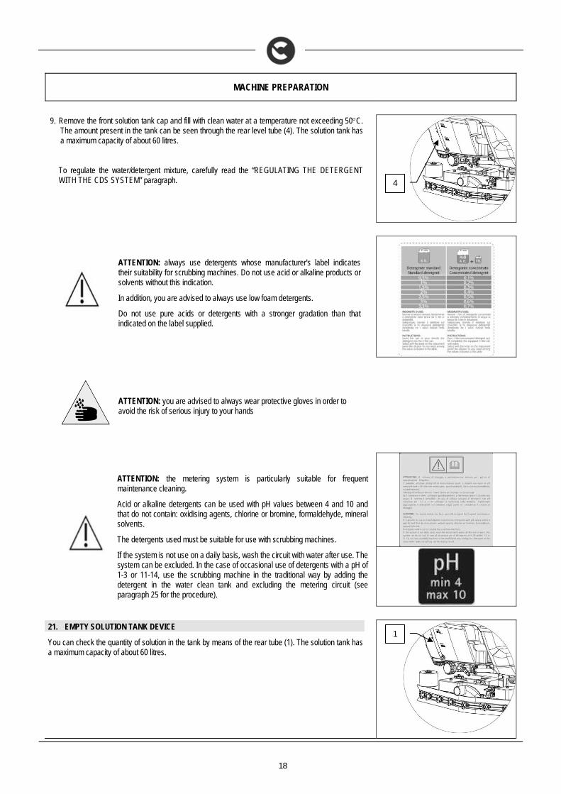
9. Remove the front solution tank cap and fill with clean water at a temperature not exceeding 50C. The amount present in the tank can be seen through the rear level tube (4). The solution tank has a maximum capacity of about 60 litres. To regulate the water/detergent mixture, carefully read the “REGULATING THE DETERGENT WITH THE CDS SYSTEM” paragraph.
ATTENTION: always use detergents whose manufacturer's label indicates their suitability for scrubbing machines. Do not use acid or alkaline products or solvents without this indication.
In addition, you are advised to always use low foam detergents.
Do not use pure acids or detergents with a stronger gradation than that indicated on the label supplied.
ATTENTION: you are advised to always wear protective gloves in order to avoid the risk of serious injury to your hands
ATTENTION: the metering system is particularly suitable for frequent maintenance cleaning.
Acid or alkaline detergents can be used with pH values between 4 and 10 and that do not contain: oxidising agents, chlorine or bromine, formaldehyde, mineral solvents.
The detergents used must be suitable for use with scrubbing machines.
If the system is not use on a daily basis, wash the circuit with water after use. The system can be excluded. In the case of occasional use of detergents with a pH of 1-3 or 11-14, use the scrubbing machine in the traditional way by adding the detergent in the water clean tank and excluding the metering circuit (see paragraph 25 for the procedure).
21. EMPTY SOLUTION TANK DEVICE
You can check the quantity of solution in the tank by means of the rear tube (1). The solution tank has a maximum capacity of about 60 litres.
1
4
19
MACHINE PREPARATION
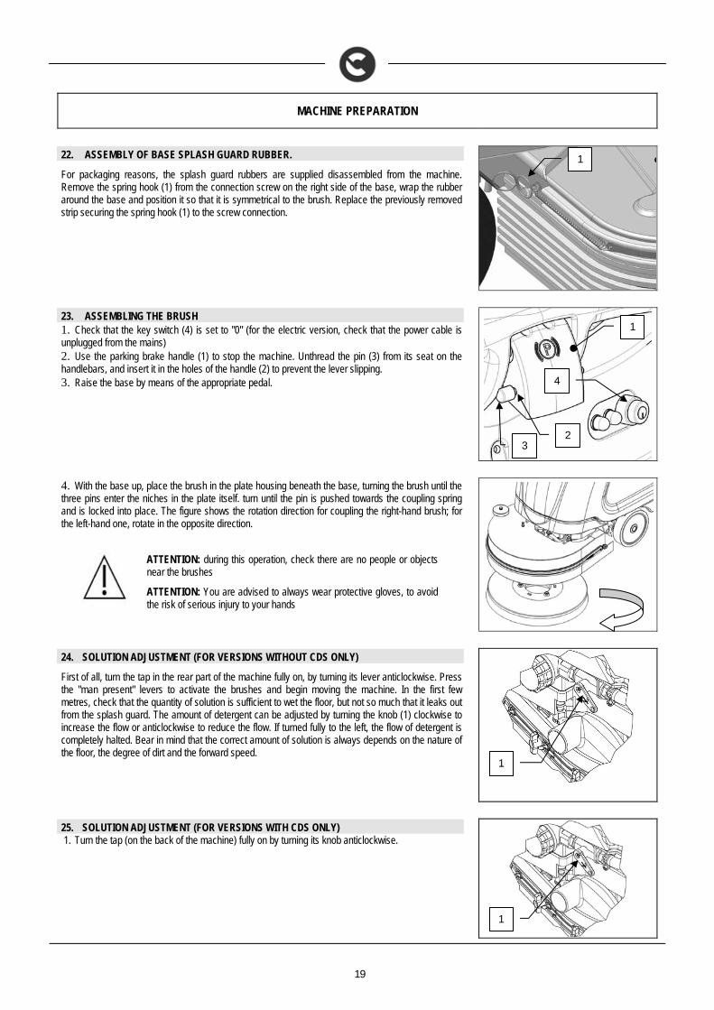
22. ASSEMBLY OF BASE SPLASH GUARD RUBBER.
For packaging reasons, the splash guard rubbers are supplied disassembled from the machine. Remove the spring hook (1) from the connection screw on the right side of the base, wrap the rubber around the base and position it so that it is symmetrical to the brush. Replace the previously removed strip securing the spring hook (1) to the screw connection.
23. ASSEMBLING THE BRUSH 1. Check that the key switch (4) is set to "0" (for the electric version, check that the power cable is unplugged from the mains) 2. Use the parking brake handle (1) to stop the machine. Unthread the pin (3) from its seat on the handlebars, and insert it in the holes of the handle (2) to prevent the lever slipping. 3. Raise the base by means of the appropriate pedal.
4. With the base up, place the brush in the plate housing beneath the base, turning the brush until the three pins enter the niches in the plate itself. turn until the pin is pushed towards the coupling spring and is locked into place. The figure shows the rotation direction for coupling the right-hand brush; for the left-hand one, rotate in the opposite direction.
ATTENTION: during this operation, check there are no people or objects near the brushes
ATTENTION: You are advised to always wear protective gloves, to avoid the risk of serious injury to your hands
24. SOLUTION ADJUSTMENT (FOR VERSIONS WITHOUT CDS ONLY)
First of all, turn the tap in the rear part of the machine fully on, by turning its lever anticlockwise. Press the "man present" levers to activate the brushes and begin moving the machine. In the first few metres, check that the quantity of solution is sufficient to wet the floor, but not so much that it leaks out from the splash guard. The amount of detergent can be adjusted by turning the knob (1) clockwise to increase the flow or anticlockwise to reduce the flow. If turned fully to the left, the flow of detergent is completely halted. Bear in mind that the correct amount of solution is always depends on the nature of the floor, the degree of dirt and the forward speed.
25. SOLUTION ADJUSTMENT (FOR VERSIONS WITH CDS ONLY) 1. Turn the tap (on the back of the machine) fully on by turning its knob anticlockwise.
1
1
2 3
4
1
1
20
MACHINE PREPARATION
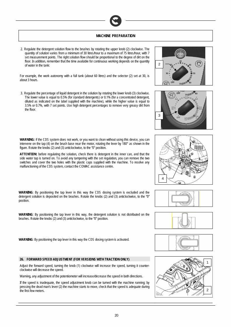
2. Regulate the detergent solution flow to the brushes by rotating the upper knob (2) clockwise. The
quantity of solution varies from a minimum of 30 litres/hour to a maximum of 75 litres/hour, with 7 set measurement points. The right solution flow should be proportional to the degree of dirt on the floor. In addition, remember that the time available for continuous working depends on the quantity of water in the tank:
For example, the work autonomy with a full tank (about 60 litres) and the selector (2) set at 30, is about 3 hours.
3. Regulate the percentage of liquid detergent in the solution by rotating the lower knob (3) clockwise.
The lower value is equal to 0.5% (for standard detergents) or 0.1% (for a concentrated detergent, diluted as indicated on the label supplied with the machine), while the higher value is equal to 3.5% or 0.7%, with 7 set points. Use high detergent percentages to remove very greasy dirt from the floor.
WARNING: if the CDS system does not work, or you want to clean without using this device, you can intervene on the tap (4) on the brush base near the motor, rotating the lever by 180° as shown in the figure. Rotate the knobs (2) and (3) anticlockwise, to the “0” position.
ATTENTION: before regulating the solution, check there is detergent in the inner can, and that the side water tap is turned on. To avoid any tampering with the set regulation, you can remove the two switches and cover the two holes with the plastic caps supplied with the machine. To resolve any malfunctioning of the CDS system, contact the COMAC assistance centre.
WARNING: By positioning the tap lever in this way the CDS dosing system is excluded and the detergent solution is deposited on the brushes. Rotate the knobs (2) and (3) anticlockwise, to the “0” position.
WARNING: By positioning the tap lever in this way, the detergent solution is not distributed on the brushes. Rotate the knobs (2) and (3) anticlockwise, to the “0” position.
WARNING: By positioning the tap lever in this way the CDS dosing system is activated.
26. FORWARD SPEED ADJUSTMENT (FOR VERSIONS WITH TRACTION ONLY)
Adjust the forward speed, turning the knob (1) clockwise will increase the speed, turning it counter-clockwise will decrease the speed.
Warning, any adjustment of the potentiometer will increase/decrease the speed in both directions.
If the speed is inadequate, the speed adjustment knob can be turned with the machine running; by pressing the dead man's lever (2) the machine starts to move, check that the speed is adequate during the first few meters.
3
2
4
2
1
21
MACHINE PREPARATION
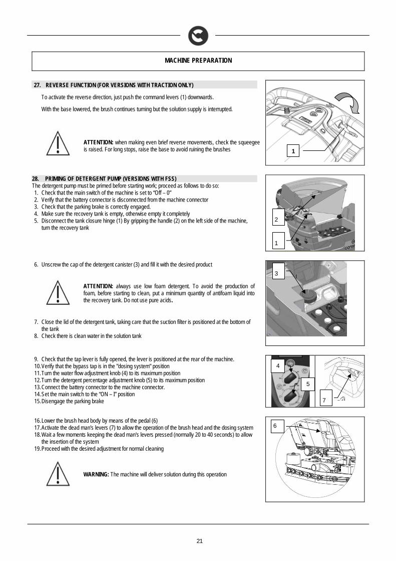
27. REVERSE FUNCTION (FOR VERSIONS WITH TRACTION ONLY)
To activate the reverse direction, just push the command levers (1) downwards.
With the base lowered, the brush continues turning but the solution supply is interrupted.
ATTENTION: when making even brief reverse movements, check the squeegee is raised. For long stops, raise the base to avoid ruining the brushes
28. PRIMING OF DETERGENT PUMP (VERSIONS WITH FSS) The detergent pump must be primed before starting work; proceed as follows to do so: 1. Check that the main switch of the machine is set to “Off – 0” 2. Verify that the battery connector is disconnected from the machine connector 3. Check that the parking brake is correctly engaged. 4. Make sure the recovery tank is empty, otherwise empty it completely 5. Disconnect the tank closure hinge (1) By gripping the handle (2) on the left side of the machine,
turn the recovery tank
6. Unscrew the cap of the detergent canister (3) and fill it with the desired product
ATTENTION: always use low foam detergent. To avoid the production of foam, before starting to clean, put a minimum quantity of antifoam liquid into the recovery tank. Do not use pure acids.
7. Close the lid of the detergent tank, taking care that the suction filter is positioned at the bottom of
the tank 8. Check there is clean water in the solution tank
9. Check that the tap lever is fully opened, the lever is positioned at the rear of the machine. 10. Verify that the bypass tap is in the "dosing system" position 11. Turn the water flow adjustment knob (4) to its maximum position 12. Turn the detergent percentage adjustment knob (5) to its maximum position 13. Connect the battery connector to the machine connector. 14. Set the main switch to the “ON – I” position 15. Disengage the parking brake
16. Lower the brush head body by means of the pedal (6) 17. Activate the dead man's levers (7) to allow the operation of the brush head and the dosing system 18. Wait a few moments keeping the dead man's levers pressed (normally 20 to 40 seconds) to allow
the insertion of the system 19. Proceed with the desired adjustment for normal cleaning
WARNING: The machine will deliver solution during this operation
1
1
2
3
7
4
5
6
22
WORK
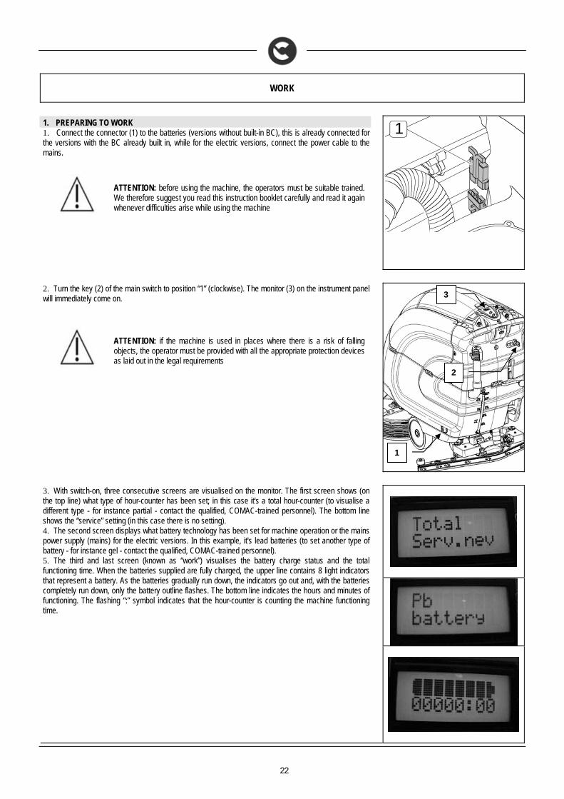
1. PREPARING TO WORK 1. Connect the connector (1) to the batteries (versions without built-in BC), this is already connected for the versions with the BC already built in, while for the electric versions, connect the power cable to the mains.
ATTENTION: before using the machine, the operators must be suitable trained. We therefore suggest you read this instruction booklet carefully and read it again whenever difficulties arise while using the machine
1
2. Turn the key (2) of the main switch to position “1” (clockwise). The monitor (3) on the instrument panel will immediately come on.
ATTENTION: if the machine is used in places where there is a risk of falling objects, the operator must be provided with all the appropriate protection devices as laid out in the legal requirements
3. With switch-on, three consecutive screens are visualised on the monitor. The first screen shows (on the top line) what type of hour-counter has been set; in this case it's a total hour-counter (to visualise a different type - for instance partial - contact the qualified, COMAC-trained personnel). The bottom line shows the “service” setting (in this case there is no setting). 4. The second screen displays what battery technology has been set for machine operation or the mains power supply (mains) for the electric versions. In this example, it's lead batteries (to set another type of battery - for instance gel - contact the qualified, COMAC-trained personnel). 5. The third and last screen (known as “work”) visualises the battery charge status and the total functioning time. When the batteries supplied are fully charged, the upper line contains 8 light indicators that represent a battery. As the batteries gradually run down, the indicators go out and, with the batteries completely run down, only the battery outline flashes. The bottom line indicates the hours and minutes of functioning. The flashing “:” symbol indicates that the hour-counter is counting the machine functioning time.
2
1
3
23
WORK
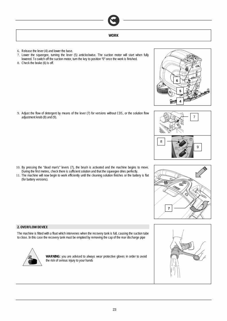
6. Release the lever (4) and lower the base. 7. Lower the squeegee, turning the lever (5) anticlockwise. The suction motor will start when fully
lowered. To switch off the suction motor, turn the key to position “0” once the work is finished. 8. Check the brake (6) is off.
9. Adjust the flow of detergent by means of the lever (7) for versions without CDS, or the solution flow adjustment knob (8) and (9).
10. By pressing the "dead man's" levers (7), the brush is activated and the machine begins to move.
During the first metres, check there is sufficient solution and that the squeegee dries perfectly. 11. The machine will now begin to work efficiently until the cleaning solution finishes or the battery is flat
(for battery versions).
2. OVERFLOW DEVICE
The machine is fitted with a float which intervenes when the recovery tank is full, causing the suction tube to close. In this case the recovery tank must be emptied by removing the cap of the rear discharge pipe
WARNING: you are advised to always wear protective gloves in order to avoid the risk of serious injury to your hands
4
5
6
7
8
9
7
24
AT THE END OF THE WORK
1. AT THE END OF WORK
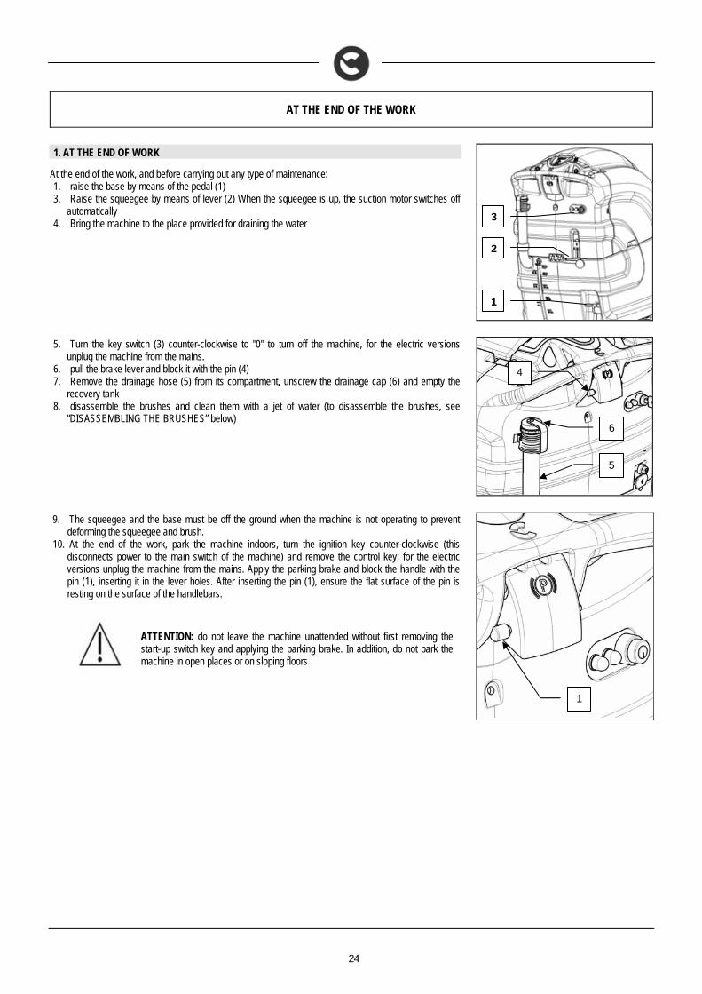
At the end of the work, and before carrying out any type of maintenance: 1. raise the base by means of the pedal (1) 3. Raise the squeegee by means of lever (2) When the squeegee is up, the suction motor switches off
automatically 4. Bring the machine to the place provided for draining the water
5. Turn the key switch (3) counter-clockwise to "0" to turn off the machine, for the electric versions
unplug the machine from the mains. 6. pull the brake lever and block it with the pin (4) 7. Remove the drainage hose (5) from its compartment, unscrew the drainage cap (6) and empty the
recovery tank 8. disassemble the brushes and clean them with a jet of water (to disassemble the brushes, see
“DISASSEMBLING THE BRUSHES” below)
9. The squeegee and the base must be off the ground when the machine is not operating to prevent
deforming the squeegee and brush. 10. At the end of the work, park the machine indoors, turn the ignition key counter-clockwise (this
disconnects power to the main switch of the machine) and remove the control key; for the electric versions unplug the machine from the mains. Apply the parking brake and block the handle with the pin (1), inserting it in the lever holes. After inserting the pin (1), ensure the flat surface of the pin is resting on the surface of the handlebars.
ATTENTION: do not leave the machine unattended without first removing the start-up switch key and applying the parking brake. In addition, do not park the machine in open places or on sloping floors
1
2
3
4
5
6
1
25
DAILY MAINTENANCE
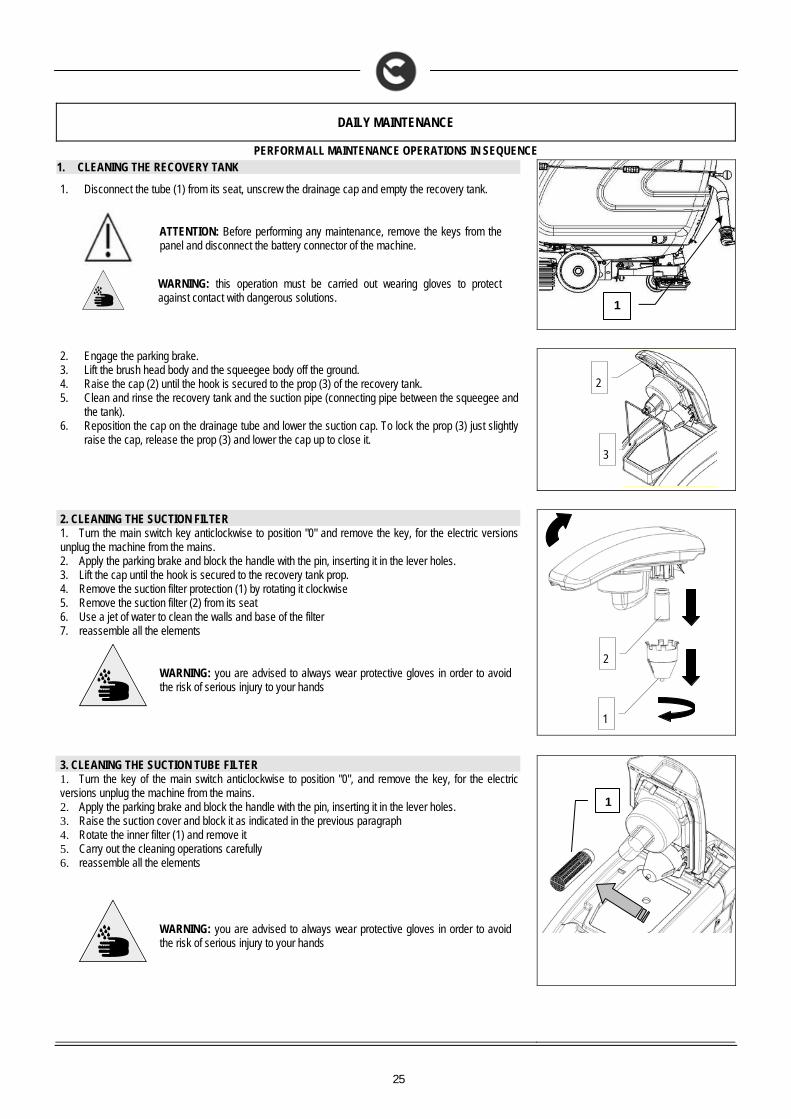
PERFORM ALL MAINTENANCE OPERATIONS IN SEQUENCE 1. CLEANING THE RECOVERY TANK
1. Disconnect the tube (1) from its seat, unscrew the drainage cap and empty the recovery tank.
ATTENTION: Before performing any maintenance, remove the keys from the panel and disconnect the battery connector of the machine.
WARNING: this operation must be carried out wearing gloves to protect against contact with dangerous solutions.
2. Engage the parking brake. 3. Lift the brush head body and the squeegee body off the ground. 4. Raise the cap (2) until the hook is secured to the prop (3) of the recovery tank. 5. Clean and rinse the recovery tank and the suction pipe (connecting pipe between the squeegee and
the tank). 6. Reposition the cap on the drainage tube and lower the suction cap. To lock the prop (3) just slightly
raise the cap, release the prop (3) and lower the cap up to close it.
2. CLEANING THE SUCTION FILTER 1. Turn the main switch key anticlockwise to position "0" and remove the key, for the electric versions unplug the machine from the mains. 2. Apply the parking brake and block the handle with the pin, inserting it in the lever holes. 3. Lift the cap until the hook is secured to the recovery tank prop. 4. Remove the suction filter protection (1) by rotating it clockwise 5. Remove the suction filter (2) from its seat 6. Use a jet of water to clean the walls and base of the filter 7. reassemble all the elements
WARNING: you are advised to always wear protective gloves in order to avoid the risk of serious injury to your hands
3. CLEANING THE SUCTION TUBE FILTER 1. Turn the key of the main switch anticlockwise to position "0", and remove the key, for the electric versions unplug the machine from the mains. 2. Apply the parking brake and block the handle with the pin, inserting it in the lever holes. 3. Raise the suction cover and block it as indicated in the previous paragraph 4. Rotate the inner filter (1) and remove it 5. Carry out the cleaning operations carefully 6. reassemble all the elements
WARNING: you are advised to always wear protective gloves in order to avoid the risk of serious injury to your hands
1
2
3
1
1
2
26
DAILY MAINTENANCE
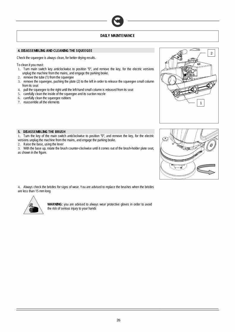
4. DISASSEMBLING AND CLEANING THE SQUEEGEE
Check the squeegee is always clean, for better drying results.
To clean it you must: 1. Turn main switch key anticlockwise to position "0", and remove the key, for the electric versions
unplug the machine from the mains, and engage the parking brake. 2. remove the tube (1) from the squeegee 3. remove the squeegee, pushing the plate (2) to the left in order to release the squeegee small column
from its seat 4. pull the squeegee to the right until the left-hand small column is released from its seat 5. carefully clean the inside of the squeegee and its suction nozzle 6. carefully clean the squeegee rubbers 7. reassemble all the elements
5. DISASSEMBLING THE BRUSH 1. Turn the key of the main switch anticlockwise to position "0", and remove the key, for the electric versions unplug the machine from the mains, and engage the parking brake. 2. Raise the base, using the lever 3. With the base up, rotate the brush counter-clockwise until it comes out of the brush-holder plate seat, as shown in the figure.
4. Always check the bristles for signs of wear. You are advised to replace the brushes when the bristles are less than 15 mm long
WARNING: you are advised to always wear protective gloves in order to avoid the risk of serious injury to your hands
1
2
27
WEEKLY MAINTENANCE
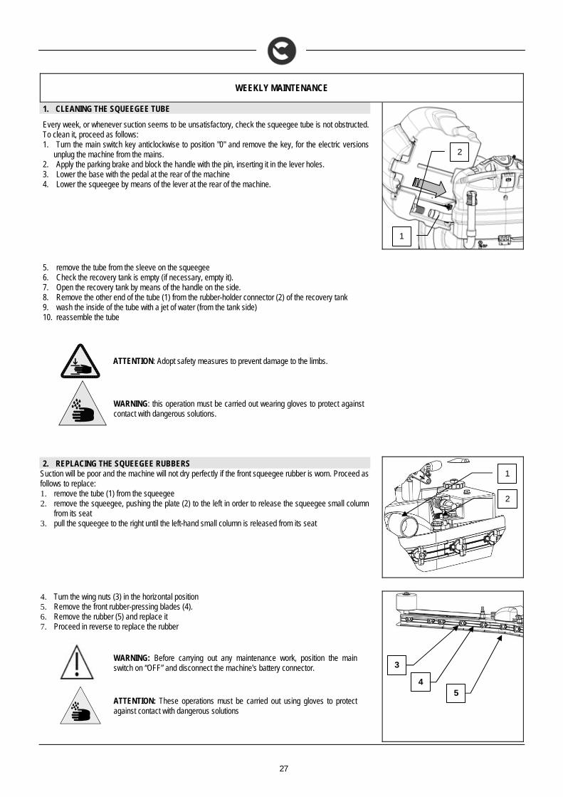
1. CLEANING THE SQUEEGEE TUBE
Every week, or whenever suction seems to be unsatisfactory, check the squeegee tube is not obstructed. To clean it, proceed as follows: 1. Turn the main switch key anticlockwise to position "0" and remove the key, for the electric versions
unplug the machine from the mains. 2. Apply the parking brake and block the handle with the pin, inserting it in the lever holes. 3. Lower the base with the pedal at the rear of the machine 4. Lower the squeegee by means of the lever at the rear of the machine.
5. remove the tube from the sleeve on the squeegee 6. Check the recovery tank is empty (if necessary, empty it). 7. Open the recovery tank by means of the handle on the side. 8. Remove the other end of the tube (1) from the rubber-holder connector (2) of the recovery tank 9. wash the inside of the tube with a jet of water (from the tank side) 10. reassemble the tube
ATTENTION: Adopt safety measures to prevent damage to the limbs.
WARNING: this operation must be carried out wearing gloves to protect against contact with dangerous solutions.
2. REPLACING THE SQUEEGEE RUBBERS
Suction will be poor and the machine will not dry perfectly if the front squeegee rubber is worn. Proceed as follows to replace: 1. remove the tube (1) from the squeegee 2. remove the squeegee, pushing the plate (2) to the left in order to release the squeegee small column
from its seat 3. pull the squeegee to the right until the left-hand small column is released from its seat
4. Turn the wing nuts (3) in the horizontal position 5. Remove the front rubber-pressing blades (4). 6. Remove the rubber (5) and replace it 7. Proceed in reverse to replace the rubber
WARNING: Before carrying out any maintenance work, position the main switch on “OFF” and disconnect the machine's battery connector.
ATTENTION: These operations must be carried out using gloves to protect against contact with dangerous solutions
1
2
2
1
3
4 5
28
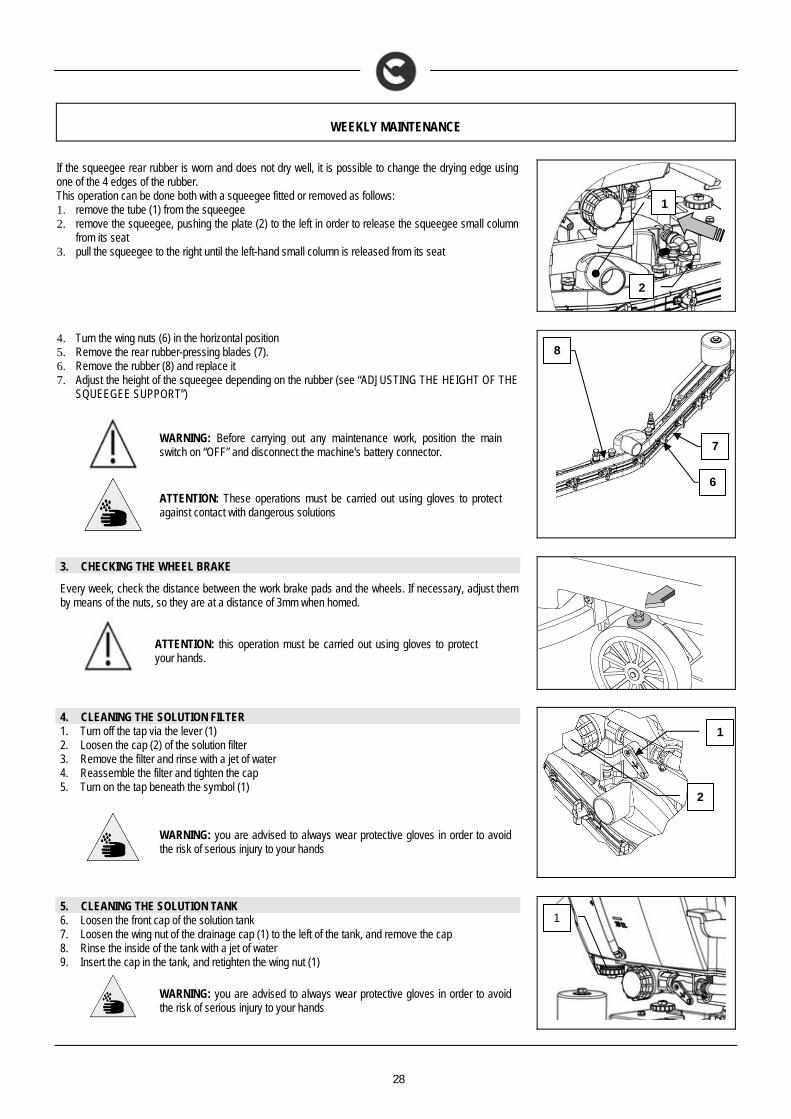
WEEKLY MAINTENANCE
If the squeegee rear rubber is worn and does not dry well, it is possible to change the drying edge using one of the 4 edges of the rubber. This operation can be done both with a squeegee fitted or removed as follows: 1. remove the tube (1) from the squeegee 2. remove the squeegee, pushing the plate (2) to the left in order to release the squeegee small column
from its seat 3. pull the squeegee to the right until the left-hand small column is released from its seat
4. Turn the wing nuts (6) in the horizontal position 5. Remove the rear rubber-pressing blades (7). 6. Remove the rubber (8) and replace it 7. Adjust the height of the squeegee depending on the rubber (see “ADJUSTING THE HEIGHT OF THE
SQUEEGEE SUPPORT”)
WARNING: Before carrying out any maintenance work, position the main switch on “OFF” and disconnect the machine's battery connector.
ATTENTION: These operations must be carried out using gloves to protect against contact with dangerous solutions
3. CHECKING THE WHEEL BRAKE
Every week, check the distance between the work brake pads and the wheels. If necessary, adjust them by means of the nuts, so they are at a distance of 3mm when homed.
ATTENTION: this operation must be carried out using gloves to protect your hands.
4. CLEANING THE SOLUTION FILTER 1. Turn off the tap via the lever (1) 2. Loosen the cap (2) of the solution filter 3. Remove the filter and rinse with a jet of water 4. Reassemble the filter and tighten the cap 5. Turn on the tap beneath the symbol (1)
WARNING: you are advised to always wear protective gloves in order to avoid the risk of serious injury to your hands
5. CLEANING THE SOLUTION TANK 6. Loosen the front cap of the solution tank 7. Loosen the wing nut of the drainage cap (1) to the left of the tank, and remove the cap 8. Rinse the inside of the tank with a jet of water 9. Insert the cap in the tank, and retighten the wing nut (1)
WARNING: you are advised to always wear protective gloves in order to avoid the risk of serious injury to your hands
1
2
2
1
8
7
6
1
29
EXTRAORDINARY MAINTENANCE
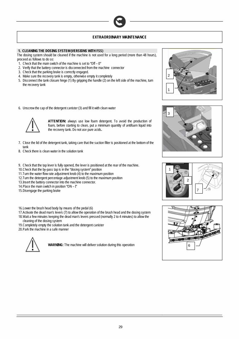
1. CLEANING THE DOSING SYSTEM (VERSIONS WITH FSS) The dosing system should be cleaned if the machine is not used for a long period (more than 48 hours), proceed as follows to do so: 1. Check that the main switch of the machine is set to “Off – 0” 2. Verify that the battery connector is disconnected from the machine connector 3. Check that the parking brake is correctly engaged. 4. Make sure the recovery tank is empty, otherwise empty it completely 5. Disconnect the tank closure hinge (1) By gripping the handle (2) on the left side of the machine, turn
the recovery tank
6. Unscrew the cap of the detergent canister (3) and fill it with clean water
ATTENTION: always use low foam detergent. To avoid the production of foam, before starting to clean, put a minimum quantity of antifoam liquid into the recovery tank. Do not use pure acids.
7. Close the lid of the detergent tank, taking care that the suction filter is positioned at the bottom of the
tank 8. Check there is clean water in the solution tank
9. Check that the tap lever is fully opened, the lever is positioned at the rear of the machine. 10. Check that the by-pass tap is in the “dosing system” position 11. Turn the water flow rate adjustment knob (4) to the maximum position 12. Turn the detergent percentage adjustment knob (5) to the maximum position 13. Insert the battery connector into the machine connector. 14. Place the main switch in position “ON – I” 15. Disengage the parking brake
16. Lower the brush head body by means of the pedal (6) 17. Activate the dead man's levers (7) to allow the operation of the brush head and the dosing system 18. Wait a few minutes keeping the dead man's levers pressed (normally 2 to 4 minutes) to allow the
cleaning of the dosing system 19. Completely empty the solution tank and the detergent canister 20. Park the machine in a safe manner
WARNING: The machine will deliver solution during this operation
1
2
3
7
1
2
6
30
TROUBLESHOOTING
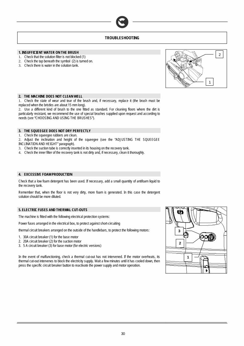
1. INSUFFICIENT WATER ON THE BRUSH 1. Check that the solution filter is not blocked (1) 2. Check the tap beneath the symbol (2) is turned on. 3. Check there is water in the solution tank.
2. THE MACHINE DOES NOT CLEAN WELL 1. Check the state of wear and tear of the brush and, if necessary, replace it (the brush must be replaced when the bristles are about 15 mm long). 2. Use a different kind of brush to the one fitted as standard. For cleaning floors where the dirt is particularly resistant, we recommend the use of special brushes supplied upon request and according to needs (see “CHOOSING AND USING THE BRUSHES”).
3. THE SQUEEGEE DOES NOT DRY PERFECTLY 1. Check the squeegee rubbers are clean. 2. Adjust the inclination and height of the squeegee (see the “ADJUSTING THE SQUEEGEE INCLINATION AND HEIGHT” paragraph). 3. Check the suction tube is correctly inserted in its housing on the recovery tank. 4. Check the inner filter of the recovery tank is not dirty and, if necessary, clean it thoroughly.
4. EXCESSIVE FOAM PRODUCTION
Check that a low foam detergent has been used. If necessary, add a small quantity of antifoam liquid to the recovery tank.
Remember that, when the floor is not very dirty, more foam is generated. In this case the detergent solution should be more diluted.
5. ELECTRIC FUSES AND THERMAL CUT-OUTS
The machine is fitted with the following electrical protection systems:
Power fuses arranged in the electrical box, to protect against short-circuiting
thermal circuit breakers arranged on the outside of the handlebars, to protect the following motors:
1. 30A circuit breaker (1) for the base motor 2. 20A circuit breaker (2) for the suction motor 3. 5 A circuit breaker (3) for base motor (for electric versions)
In the event of malfunctioning, check a thermal cut-out has not intervened. If the motor overheats, its thermal cut-out intervenes to block the electricity supply. Wait a few minutes until it has cooled down, then press the specific circuit breaker button to reactivate the power supply and motor operation.
1
1
2
3
2
31
DISPOSAL
To dispose of the machine, take it to a demolition centre or an authorised collection centre.
Before scrapping the machine it is necessary to remove and separate the following materials and send them to the appropriate collection centres in accordance with the environmental hygiene regulations currently in force: brushes filter electric and electronic parts* batteries plastic parts (tanks and handlebars) metal parts (levers and frame)
(*) In particular, to scrap the electric and electronic parts, contact your area distributor
32
CHOOSING AND USING THE BRUSHES
POLYPROPYLENE BRUSH (PPL)
Used on all types of floors. Good resistance to wear and tear, and hot water (no greater than 60°C). The Polypropylene brush is non-hygroscopic and therefore retains its characteristics even when working in wet conditions.
ABRASIVE BRUSH
The bristles of this type of brush are charged with highly aggressive abrasives. It is used to clean very dirty floors. To avoid floor damage, work only with the pressure strictly necessary.
THICKNESS OF THE BRISTLES
Thicker bristles are more rigid and are therefore used on smooth floors or floors with small joints.
On uneven floors or those with deep joints, it is advisable to use softer bristles which can enter the gaps more easily.
Remember that when the bristles are worn and therefore too short, they will become rigid and are no longer able to penetrate and clean deep down. In this case, like with overlarge bristles, the brush tends to jump.
PAD HOLDER
The pad holder is recommended for cleaning shiny surfaces.
There are two types of pad holder: 1. the traditional pad holder is fitted with a series of anchor points that allow the abrasive floor pad to be held and dragged while working 2. the CENTRE LOCK type pad holder not only has anchor points, but also a snap-type central locking system in plastic that allows the abrasive floor pad to be perfectly centred and held without any risk of it becoming detached. This type of dragging device is recommended above all for machines with more than one brush, where the centring of the abrasive discs is difficult
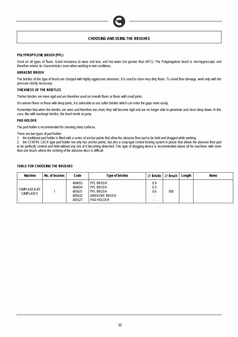
TABLE FOR CHOOSING THE BRUSHES
Machine No. of brushes Code Type of bristles Bristles
Brush Length Notes
SIMPLA50 B-BT SIMPLA50 E
1
404653 404654 405631 405632 405527
PPL BRUSH PPL BRUSH PPL BRUSH ABRASIVE BRUSH PAD HOLDER
0.9 0.3 0.6 - -
500
33
EC DECLARATION OF COMPLIANCE
The undersigned manufacturer:
COMAC S.p.A. Via Maestri del Lavoro, 13
37059 Santa Maria di Zevio (VR) declares under its sole responsibility that the products
SCRUBBING MACHINES mod. SIMPLA50 B – SIMPLA50 BT
comply with the requirements of the following Directives:
2006/42/EC: Machinery Directive 2006/95/EC: Low Voltage Directive 2004/108/EC: Electromagnetic Compatibility Directive
They also comply with the following standards: EN 60335-1: Household and similar electrical appliances - Safety. Part 1: Generic standards EN 60335-2-72: Household and similar electrical appliances. Part 2: Generic standards for automatic machines for floor treatment for commercial and
industrial use EN 60335-2-29: Household and similar electrical appliances. Part 2: Special standards for battery chargers. EN 12100-1: Machine safety - Fundamental concepts, fundamental principles of design - Part 1: Basic terminology and methodology EN 12100-2: Machine safety - Fundamental concepts, fundamental principles of design - Part 2: Technical principles EN 61000-6-2: Electromagnetic compatibility (EMC) - Part 6-2: Generic standards – Immunity for industrial environments. EN 61000-6-3: Electromagnetic compatibility (EMC) - Part 6-3: Generic standards — Standard emission for residential, commercial and light-industrial
environments. EN 61000-3-2: Electromagnetic compatibility (EMC) - Part 3-2: Limits – Limits for harmonic current emissions (Equipment with input current 16 A per
phase). EN 61000-3-3: Electromagnetic compatibility (EMC) - Part 3-3: Limits – Restriction of voltage variations and flicker in low voltage power supply systems
for devices with a rated current 16 A. EN 55014-1: Electromagnetic compatibility - Regulations for household appliances, electrical devices and similar equipment. Part 1: Emission -
Regulation for product family. EN 55014-2: Electromagnetic compatibility - Regulations for household appliances, electrical devices and similar equipment. Part 2: Immunity -
Regulation for product family. EN 62233: Household and similar electrical appliances - Electromagnetic fields Methods for evaluation and measurement The person authorised to compile the technical file: Sig. Giancarlo Ruffo Via Maestri del Lavoro, 13 37059 Santa Maria di Zevio (VR) - ITALY Santa Maria di Zevio (VR), 18/10/2010
COMAC S.p.A. Legal representative
Giancarlo Ruffo
COMAC spa Via Maestri del Lavoro, 13 – 37059 Santa Maria di Zevio – Verona – ITALY
Tel. +39 045 8774222 – Fax +39 045 8750303 - E-mail: [email protected] o [email protected] - www.comac.it
34
EC DECLARATION OF COMPLIANCE
The undersigned company:
COMAC S.p.A. Via Maestri del Lavoro, 13
37059 Santa Maria di Zevio (VR) declares under its sole responsibility that the products
SCRUBBING MACHINES mod. SIMPLA50 E
comply with the requirements of the following Directives:
2006/42/EC: Machinery Directive 2006/95/EC: Low Voltage Directive 2004/108/EC: Electromagnetic Compatibility Directive
They also comply with the following standards: EN 60335-1: Household and similar electrical appliances - Safety. Part 1: Generic norms EN 60335-2-72: Household and similar electrical appliances. Part 2: Specific norms for automatic machines for floor treatment for commercial and
industrial use EN 12100-1: Machine safety - Fundamental concepts, fundamental principles of design - Part 1: Basic terminology and methodology EN 12100-2: Machine safety - Fundamental concepts, fundamental principles of design - Part 2: Technical principles EN 55014-1: Electromagnetic compatibility - Regulations for household appliances, electrical devices and similar equipment. Part 1: Emission -
Regulations for product family. EN 55014-2: Electromagnetic compatibility - Regulations for household appliances, electrical devices and similar equipment. Part 2: Immunity -
Regulations for product family. EN 61000-3-2: Electromagnetic compatibility (EMC) - Part 3-2: Limits – Limits for harmonic current emissions (Equipment with input current 16 A per
phase). EN 61000-3-3: Electromagnetic compatibility (EMC) - Part 3-3: Limits – Restriction of voltage variations and flicker in low voltage power supply systems
for devices with a rated current 16 A. EN 62233: Household and similar electrical appliances - Electromagnetic fields Methods for evaluation and measurement The person authorised to compile the technical file: Sig. Giancarlo Ruffo Via Maestri del Lavoro, 13 37059 Santa Maria di Zevio (VR) - ITALY Santa Maria di Zevio (VR), 18/10/2010
COMAC S.p.A. Legal representative
Giancarlo Ruffo
COMAC spa Via Maestri del Lavoro, 13 – 37059 Santa Maria di Zevio – Verona – ITALY
Tel. +39 045 8774222 – Fax +39 045 8750303 - E-mail: [email protected] o [email protected] - www.comac.it

35
COMAC spa Via Maestri del Lavoro, 13 – 37059 Santa Maria di Zevio – Verona – ITALY
Tel. +39 045 8774222 – Fax +39 045 8750303 - E-mail: [email protected] o [email protected] - www.comac.it

36
COMAC spa Via Maestri del Lavoro, 13 – 37059 Santa Maria di Zevio – Verona – ITALY
Tel. +39 045 8774222 – Fax +39 045 8750303 - E-mail: [email protected] o [email protected] - www.comac.it