Embed Size (px)
Citation preview

Aqua Ionic Plus – MAN00016 Rev. B – 29.03.98 1 / 22
USE AND MAINTENANCE MANUAL
AQUA IONIC PLUS
Aqua Ionic Plus – MAN00016 Rev. B – 29.03.98 2 / 22
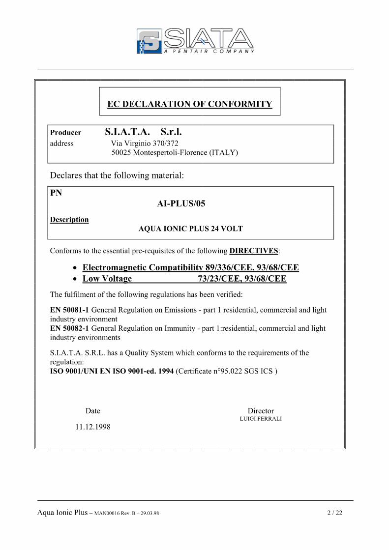
EC DECLARATION OF CONFORMITY
Producer S.I.A.T.A. S.r.l.
address Via Virginio 370/372 50025 Montespertoli-Florence (ITALY)
Declares that the following material:
PN AI-PLUS/05
Description AQUA IONIC PLUS 24 VOLT
Conforms to the essential pre-requisites of the following DIRECTIVES:
• Electromagnetic Compatibility 89/336/CEE, 93/68/CEE • Low Voltage 73/23/CEE, 93/68/CEE
The fulfilment of the following regulations has been verified:
EN 50081-1 General Regulation on Emissions - part 1 residential, commercial and light industry environment
EN 50082-1 General Regulation on Immunity - part 1:residential, commercial and light industry environments
S.I.A.T.A. S.R.L. has a Quality System which conforms to the requirements of the regulation: ISO 9001/UNI EN ISO 9001-ed. 1994 (Certificate n°95.022 SGS ICS )
Date Director LUIGI FERRALI
11.12.1998

Aqua Ionic Plus – MAN00016 Rev. B – 29.03.98 3 / 22
Index
1 - INTRODUCTION........................................................................................................................ 4
2 - TECHNICAL DATA.................................................................................................................... 5
3 – EXPLANATION OF THE LED AND THE KEYS ................................................................... 6
4 – VISUALISATION STAGES OF THE DISPLAY ..................................................................... 6
5 - GENERAL ................................................................................................................................... 7 5.1 – Packaging and storage.......................................................................................................................7
5.2 – Installation..........................................................................................................................................7
5.3 – Electrical connections ........................................................................................................................7
5.4 – Protection devices ..............................................................................................................................7
6 – ISTRUCTIONS FOR USE ......................................................................................................... 8 6.1 – Turning on..........................................................................................................................................8
6.2 – Programming codes 8 6.2.1 – Access to the programming codes ............................................................................................. 8 6.2.2 – List of programming codes and their meanings............................................................................................ 9 6.2.3 – SC01 – Programming of regeneration cycle times ..................................................................................... 10
6.2.3.1 – A particular cycle: 8+8 ........................................................................................................................ 12 6.2.4 – SC02 - Programming of operation times in case of set point ..................................................................... 13 6.2.5 – SC03 - Resetting of the scale of the conductivity probe and of the value of set point. .............................. 16 6.2.6 – SC04 - Resetting. of the volume and of the meter divider.......................................................................... 16 6.2.7 – SC05 - Selection of the of the control modality for the start-up of the regeneration................................. 17 6.2.8 – SC06 - Selection of the SuperAutomatic modality..................................................................................... 18 6.2.9 – SC07 - Setting of the access code............................................................................................................... 18 6.2.10 – SC08 – Use of the recirculation pump...................................................................................................... 18 6.2.11 – SC09 – Resetting of the volume value...................................................................................................... 19
6.3 - Remote start ......................................................................................................................................19
6.4–Putting into service ...........................................................................................................................19
7 – What to do if… .......................................................................................................................... 20 7.1 - ... Aqua Ionic Plus does not come on ?............................................................................................20
7.2 - ... the motors of the distributors do not stop ? ...............................................................................20
7.3 - ...there is no current to the utilisers ? .............................................................................................20
7.4 - ... Aqua Ionic Plus works in an irregular way ? ............................................................................20
7.5 - ... the conductivity reading is incorrect ? .......................................................................................20
Attachment A................................................................................................................................... 21
Attachment B................................................................................................................................... 22

Aqua Ionic Plus – MAN00016 Rev. B – 29.03.98 4 / 22
1 - INTRODUCTION Aqua Ionic Plus is a controller dedicated to the production of water treatment systems working on the principle of ionic resin exchange, which allows the production of demineralisation systems. Aqua Ionic Plus allows for one or two distributors to be controlled, and in the latter case, for the number of regenerations of the cathode which have to be carried out before the regeneration of the anode to be set, up to a maximum of 6. The regeneration cycle is completely programmable: it can be started by a control on the conductivity, on the volume by an external signal or manually; it is possible to cancel the entire cycle or to jump one or more phases. Aqua Ionic Plus can operate the regeneration in SuperAutomatic; if the regeneration is successful, it is stopped before the natural end of the times set, so as not to consume water unnecessarily. If the regeneration is not successful, an alarm is set off and successive chain regenerations are blocked Aqua Ionic Plus can be connected to a computer via RS232 using the cable cod. 881-1, so as to be able to acquire and then analyse the progress of the work parameters. Aqua Ionic Plus is equipped with a buffer battery which allows the work parameters to be memorised should the electricity supply cut out. Aqua Ionic Plus is equipped with an EEPROM memory where the programmed data is memorised, with the capacity to retain data for over 10 years. Aqua Ionic Plus, like all of the range of SIATA controllers, conforms to the EEC Directives and is produced in the SIATA plant of Montespertoli operating with the certified Quality System according to the regulations of:
ISO 9001 / UNI EN ISO 9001.

Aqua Ionic Plus – MAN00016 Rev. B – 29.03.98 5 / 22
2 – TECHNICAL DATA
Supply voltage 24 Vac ± 10% Network frequency 50 Hz ± 3% Power absorbed 20 VA Operating temperature 0° C – 55° C Class of protection IP65 Protection from disturbances ICE 65 Trial class 4 ( 3000 V ) Reading scale 0 – 2500 µS Container dimensions 240 mm x 185 mm x 115 mm Total weight 1.5 Kg

Aqua Ionic Plus – MAN00016 Rev. B – 29.03.98 6 / 22
3 – DESCRIPTION OF THE LEDS AND OF THE KEYS
Tab. 1 – Functioning of the LEDs
LED Meaning SET POINT The value of the conductivity has reached the pre-set set point
ALARM Aqua Ionic Plus is blocked because of an alarm condition EXT ALARM. External alarm. An inhibit signal is present. INT. ALARM Internal alarm. The regeneration has not been successful
AUTO VOLUME Start-up of the regeneration by volume AUTO SET POINT Start-up of the regeneration by conductivity
MANUAL Manual start-up of the regeneration SUPER AUTOM. SuperAutomatico operating modality active
The signs Auto Volume, Auto Set point e Manual, may be combined with the code SC05. See par.. 6.37
Tab. 2 – Functioning of the keys CODE Access to the programming of the work parameters via the protection code.
RESET
Allows exiting from the programming without memorising the last value inputted. If there is a regeneration in progress, this stops it.
Pressed after Program, accesses the selection of the codes.
PROGRAM Gives access to the programming functions
DISPLAY. Changes the mode of visualisation of the display During the programming, resets to zero the value being changed.
ADVANCE In programming increases the value on the display.
REGENER. Starts up the regeneration. During a stop phase, cancels the residual time and moves on to the next phase.
4 – VISUALISATION STATES OF THE DISPLAY The display allows for visualisation of various operative states and/or data, to be selected using the key Display ;
Tab. 3 – Visualisation Display
Display Operative state / Visualised data
Display 0 1 0 0 The value of conductivity read by the probe
Display 0.0.5 0 Value of pre-set set point
Display 0 5.0 0 The volume of water available
- - - - No regeneration in progress Display
1 C 2 5 Regeneration in progress

Aqua Ionic Plus – MAN00016 Rev. B – 29.03.98 7 / 22
5 - GENERAL 5.1 – Packaging and storage The packaging consists of a cardboard box, with a label identifying the product and containing the following information: the name of the producer and the PN producer AI-PLUS1/05; inside the quick reference guide for the programming and installation, can be found. No particular procedures are necessary for the removal from the packaging. The appliance must be stored in environments with the following characteristics:
- 0°C e +55°C; - relative humidity 30 % e 95 %.
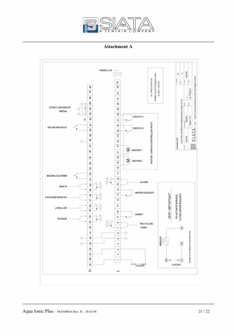
5.2 – Installation The installation of the controller must be carried out by qualified personnel. The appliance consists of a PVC box with a cover in plexi-glass which may be opened manually, giving access to the keypad, and of a cover which may be removed by loosening two screws and which gives access to the external connection terminal board. The box is covered by a certificate with the IP65 grade of protection, Aqua Ionic Plus is therefore protected against infiltration of dust and direct jets of water. This protection is valid when the cover is closed, and the wiring slots are of the correct size for the wires used and are correctly assembled. If these conditions are not fulfilled, the level of protection falls to IP40, which gives no protection against infiltration of dust and water. The back of the box is equipped with mechanical details which allow it to be wall-mounted. 5.3 – Electrical connections The electrical connection of the controller must take place conforming to the conditions stated in the diagram CE0043 shown on attachment A The appliance includes free contact exits with the following indications :
• Service; • Draining; • Regeneration in progress. • Recirculation pump;
Warning!! Before carrying out any installation and/or maintenance operation, check that the controller is disconnected from the electricity supply. The supply to the controller must take place in accordance with all that is indicated in par 2. A connection of the appliance to the general earth line of the main electrical system should be carried out. 5.4 – Protection devices The appliance is protected from current overloads by a 1.6A supply retardant fuse which is assembled on the front panel (T 6.3A). It is also protected against disturbances originating from the electricity supply by an LC filter, and is equipped with an auto reset circuit which resolves conditions in which the controller is blocked.

Aqua Ionic Plus – MAN00016 Rev. B – 29.03.98 8 / 22
6 – INSTRUCTIONS FOR USE 6.1 – Turning on The appliance is turned on via the main switch ON (I) - OFF (0) situated on the front panel. This switch acts on both supply wires The supply voltage must be 24 Vac - 50 Hz. Check the supply voltage using the adhesive labels situated on the cover of the connections. 6.2 – Programming codes Aqua Ionic Plus allows access to the programming functions even if the limit switch entries of the two motors are open. These entries must be closed ( even if only with a bridge if a complete distributor is not available ) as soon as the controller is to be put into service. The programming is carried out using the keypad on the front panel of the appliance. Whichever programming is set with the codes described on the following pages, Aqua Ionic Plus only has the function of controlling the only two parameters which communicate the operative state of the system: the conductivity and the volume. On the basis of these parameters and on the basis of the data setting with the code SC05, see par. 6.2.7, Aqua Ionic Plus will start up the regeneration until the conditions required have been reached. 6.2.1 – Access to the programming codes The following is the sequence of keys to press in order to access the programming functions :
Tab. 4 – Access to the programming codes
Display Meaning
PROGRAM S 0 S 0 First step for access to the programming functions RESET S C 0 0 Access to the programming functions
ADVANCE S C 0 1 With the key Advance select the required code PROGRAM S C 0 1 Confirms the code selected and accesses its programming
If a protection code is set with the function SC07, see par. 6.2.9, the succession shown in tab. 4 varies as follows:
Tab. 5 – Access to the programming codes via the protection codes
Display Meaning
CODE 0.0.0.0. Entry to the function of the inputting of the protection code ADVANCE 0.2.0.1. With the key Advance and the key Code the protection code is inputted
CODE S 0 S 0 First step for access to the programming functions RESET S C 0 0 Access to the programming functions
ADVANCE S C 0 1 With the key Advance select the required code PROGRAM S C 0 1 Confirm the code selected and access its programming
Aqua Ionic Plus – MAN00016 Rev. B – 29.03.98 9 / 22
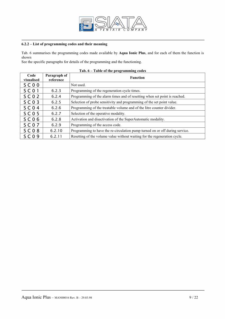
6.2.2 – List of programming codes and their meaning Tab. 6 summarises the programming codes made available by Aqua Ionic Plus, and for each of them the function is shown See the specific paragraphs for details of the programming and the functioning.
Tab. 6 – Table of the programming codes Code
visualised Paragraph of
reference Function
S C 0 0 Not used. S C 0 1 6.2.3 Programming of the regeneration cycle times. S C 0 2 6.2.4 Programming of the alarm times and of resetting when set point is reached. S C 0 3 6.2.5 Selection of probe sensitivity and programming of the set point value. S C 0 4 6.2.6 Programming of the treatable volume and of the litre counter divider. S C 0 5 6.2.7 Selection of the operative modality. S C 0 6 6.2.8 Activation and disactivation of the SuperAutomatic modality. S C 0 7 6.2.9 Programming of the access code. S C 0 8 6.2.10 Programming to have the re-circulation pump turned on or off during service. S C 0 9 6.2.11 Resetting of the volume value without waiting for the regeneration cycle.

Aqua Ionic Plus – MAN00016 Rev. B – 29.03.98 10 / 22
6.2.3 – SC01 – Programming of the regeneration cycle times With this code the programming of the parameters regulating the regeneration cycle may be accessed. Depending on the number of distributors present and on the number of phases the cycle is to be composed of, the sequence of programming of the times will change. The following tables illustrate the various differences. In the following descriptions, the cathode and anode columns are referred to. The cathode column is the one connected to the terminals of column 1, while the anode column is connected to the terminals of column 2 . When only one distributor is in use, this should be connected to the terminals of column 2. See attachment A. To use only one distributor, the voice -- tx must be set on 1 . This appears as soon as the programming code SC01 is entered into. Using a single distributor means that the two ( anionic and cationic ) columns are regenerated in sequence, since the distributor cam works on 360°. Aqua Ionic Plus allows for the number of steps to be carried out during the regeneration cycle, to be selected. Selecting 8 stop, a system composed of the cathode column and the anode column is, produced with each of them regenerated with a cycle of 4. The movement times are of 27”. Selecting 9 stop, a system composed of three columns is produced; a cathode, a weak anode and a strong anode, always regenerated in sequence, in a cycle with movement times of 25”. The voice CA01, regeneration link between cathode and anode, has no effect working with a single distributor, since the two columns are always regenerated in sequence. The programming of the stop times of the various phases sees the sequence of the numbers of the cycle go from phase 1C to phase 8C if 8 stops have been programmed, or to phase 9C if Aqua Ionic Plus is programmed for 9 stops. IMPORTANT !!! When only one distributor is used, this is connected to the terminals of motor 2. ( See attachment A)
Tab. 7 – Regeneration cycle of 8 phases with one distributor
Display Meaning
PROGRAM - - t 1 The controller is connected to a single distributor. PROGRAM S t 0 8 The regeneration is composed of 8 phases. PROGRAM C A 0 1 Programming with no effect when working with a single distributor. PROGRAM 1 C x x Stop time of the first phase of the cycle of regeneration, the first of the cathode. PROGRAM 2 C x x Stop time of the second phase of the cycle of regeneration, the second of the cathode. PROGRAM 3 C x x Stop time of the third phase of the cycle of regeneration, the third of the cathode. PROGRAM 4 C x x Stop time of the fourth phase of the cycle of regeneration, the fourth of the cathode. PROGRAM 5 C x x Stop time of the fifth phase of the cycle of regeneration, the first of the anode. PROGRAM 6 C x x Stop time of the sixth phase of the cycle of regeneration, the second of the anode. PROGRAM 7 C x x Stop time of the seventh phase of the cycle of regeneration, the third of the anode. PROGRAM 8 C x x Stop time of the eighth phase of the regeneration cycle, the fourth of the anode.

Aqua Ionic Plus – MAN00016 Rev. B – 29.03.98 11 / 22
When programming the controller to have a regeneration cycle of 9 phases, it is possible to use the single distributor to control the 3 columns which will be regenerated in sequence.
Tab. 8 – Cycle of regeneration of 9 phases with one distributor
Display Meaning
PROGRAM - - t 1 The controller is connected to a single distributor. PROGRAM S t 0 9 The regeneration is composed of 9 phases. PROGRAM C A 0 1 Programming with no effect when working with a single distributor. PROGRAM 1 C x x Stop time of the first phase of the regeneration cycle, the first of the first column. PROGRAM 2 C x x Stop time of the second phase of the regeneration cycle, the second of the first column. PROGRAM 3 C x x Stop time of the third phase of the regeneration cycle, the third of the first column. PROGRAM 4 C x x Stop time of the fourth phase of the regeneration cycle, the first of the second column. PROGRAM 5 C x x Stop time of the fifth phase of the regeneration cycle, the second of the second column. PROGRAM 6 C x x Stop time of the sixth phase of the regeneration cycle, the third of the second column. PROGRAM 7 C x x Stop time of the seventh phase of the regeneration cycle, the first of the third column. PROGRAM 8 C x x Stop time of the eighth phase of the regeneration cycle, the second of the third column. PROGRAM 9 C x x Stop time of the ninth phase of the regeneration cycle, the third of the third column. To use two distributors, the value 2 must be set in the voice --tx, which appears as soon as the programming code SC01 is entered. The first distributor is connected to the cathode column ( using the terminals of the motor 1), while the second is connected to the anode column ( using the terminals of the motor 2 ). This type of system is used programming the number of stops of the regeneration at 8, 4 for each column, a setting which uses movement times of 50”. Using two distributors, the voice CA01 allows the programming of the number of regenerations to be carried out with the cathode before carrying out a regeneration of the anode. The value may be set from 1 to 6. The programming of the stop times of the regeneration cycle, sees the first 4 phases dedicated to the cathode column numbered from 1C to 4C, then pass to the anode column, the 4 phases of which are numbered from 1A to 4A.
Tab. 9 – Cycle of regeneration of 8 phases con due distributors
Display Meaning
PROGRAM - - t 2 The controller is connected to two distributors. PROGRAM S t 0 8 The regeneration is composed of 8 phases . PROGRAM C A 0 1 Link between the regenerations of the cathode and of the anode. PROGRAM 1 C x x Stop time of the first phase of the regeneration cycle of the cathode. PROGRAM 2 C x x Stop time of the second phase of the regeneration cycle of the cathode. PROGRAM 3 C x x Stop time of the third phase of the regeneration cycle of the cathode. PROGRAM 4 C x x Stop time of the fourth phase of the regeneration cycle of the cathode. PROGRAM 1 A x x Stop time of the first phase of the regeneration cycle of the anode. PROGRAM 2 A x x Stop time of the second phase of the regeneration cycle of the anode. PROGRAM 3 A x x Stop time of the third phase of the regeneration cycle of the anode. PROGRAM 4 A x x Stop time of the fourth phase of the regeneration cycle of the anode.

Aqua Ionic Plus – MAN00016 Rev. B – 29.03.98 12 / 22
Tab. 10 – Regeneration cycle of 9 phases with two distributors
Display Meaning
PROGRAM - - t 2 The controller is connected to two distributors. PROGRAM S t 0 9 The regeneration is composed of 9 phases PROGRAM C A 0 1 Programming with no effect when working with a single distributor. PROGRAM 1 C x x Stop time of the first phase of the regeneration cycle, the first of the cathode. PROGRAM 2 C x x Stop time of the second phase of the regeneration cycle, the second of the cathode. PROGRAM 3 C x x Stop time of the third phase of the regeneration cycle, the third of the cathode. PROGRAM 4 C x x Stop time of the fourth phase of the regeneration cycle, the fourth of the cathode. PROGRAM 1 A x x Stop time of the fifth phase of the regeneration cycle, the first of the anode. PROGRAM 2 A x x Stop time of the sixth phase of the regeneration cycle, the second of the anode. PROGRAM 3 A x x Stop time of the seventh phase of the regeneration cycle, the third of the anode. PROGRAM 4 A x x Stop time of the eighth phase of the regeneration cycle, the fourth of the anode. PROGRAM 5 A x x Stop time of the ninth phase of the regeneration cycle, the fifth of the anode. The link between the regenerations of the cathode and of the anode indicates how many cycles of the cathode must be carried out for each cycle of the anode. Programming the value CA03 means that at the end of the third cycle of the cathode, the cycle of the anode starts. 6.2.3.1 – A particular cycle : 8+8 To produce a system made up of a cathode column, a weak anode column and a strong anode column, a particular version of the controller has been designed, the Aqua Ionic Plus, with a particular management of the regeneration cycle. This version, called 8+8, allows for all the details of the regeneration cycle, the number of steps to be carried out and the motor rotation times, diversified for the two columns, to be programmed. For example, to produce the above system it is possible to programme the controller to have a cycle of the cathode made up of 4 phases of 50 seconds of movement and the anode cycle composed of 8 phases of 27 seconds of movement. The distributors must have 3 pilots for the cathode and 6 pilots for the anode. An electrovalve must also be used for the stopping of the service. To summarise, the following table shows the sequence of programming which produces the example shown.
Display Meaning
PROGRAM C – 0 4 The number of phases for the cathode column. Variable from 4 a 8. PROGRAM A – 0 8 The number of phases for the column anode. Variable from 4 a 8.
PROGRAM C A 0 1 The link of regenerations between the cathode column e the anode column. Variable from 1 a 5.
PROGRAM S C 5 0 The time of rotation of the motor of the cathode column. Variable from 0 a 98 seconds PROGRAM S A 2 7 The time of rotation of the motor of the anode column. Variable from 0 a 98 seconds. PROGRAM 1 C x x Stop time of the first phase of the cathode column. PROGRAM 2 C x x Stop time of the second phase of the cathode column.

Aqua Ionic Plus – MAN00016 Rev. B – 29.03.98 13 / 22
PROGRAM 3 C x x Stop time of the third phase of the cathode column. PROGRAM 4 C x x Stop time of the fourth phase of the cathode column. PROGRAM 5 C 0 0 Stop time of the fifth phase of the cathode column. PROGRAM 6 C 0 0 Stop time of the sixth phase of the cathode column. PROGRAM 7 C 0 0 Stop time of the seventh phase of the cathode column. PROGRAM 8 C 0 0 Stop time of the eighth phase of the cathode column. PROGRAM 1 A x x Stop time of the first phase of the anode column. The first of the weak anode. PROGRAM 2 A x x Stop time of the second phase of the anode column. The second of the weak anode. PROGRAM 3 A x x Stop time of the third phase of the anode column. The third of the weak anode. PROGRAM 4 A x x Stop time of the fourth phase of the anode column. The fourth of the weak anode. PROGRAM 5 A x x Stop time of the fifth phase of the anode column. The first of the strong anode. PROGRAM 6 A x x Stop time of the sixth phase of the anode column. The second of the strong anode. PROGRAM 7 A x x Stop time of the seventh phase of the anode column. The third of the strong anode. PROGRAM 8 A x x Stop time of the eighth phase of the anode column. The fourth of the strong anode. N.B. During the programming of the stop times of the regeneration cycle, the controller also shows on the Display the times of the phases not requested. With reference to the example and to the table shown above, it can be seen that the controller asks for the times of the phases from 5 to 8 of the cathode column even though only 4 phases are required. Any times different from zero programmed in these phases will be ignored by the controller when the regeneration cycle is carried out. 6.2.4 – SC02 - Programming of the operation times in case of set point With this programming code, two operation times are set. The first, 1txx, is the time in minutes which passes from the moment in which the Aqua Ionic Plus shows a value of conductivity over and above the value of set point, and the start-up of regeneration . It can assume values of between 1 and 98 minutes. The second, 0txx, is the time in minutes during which it is checked that the value of conductivity, which during the passing of the time 1txx returned to within the limits of the set point, does not rise again above the limits set. It can assume values of between 0 and 20 minutes. The following points describe the behaviour of Aqua Ionic Plus in the various operative conditions, first in the case in which the level of conductivity rises above the set point for the whole length of time indicated in 1txx, and then the case in which the level of conductivity returns to within the limits of the set point during the length of time indicated in 1txx; 1. Start-up of the regeneration in Auto Set point :
1.1. Not in service. 1.1.1. The recirculation pump is on. At the moment the set point is reached, the discharge valve is
activated and the countdown of the time set in 1txx starts .At the end of this time, regeneration starts.
1.1.2. If the value of conductivity returns to within the limits before the time set on 1txx is up, the discharge valve is closed. If during this time the vale of conductivity rises again above the value of set point, operations start again from point 1.1.1.
1.2. Not in service, there is an inhibit signal.. 1.2.1. The recirculation pump is on. On the panel the LED External Alarm is on. The exit Alarm
is active. The moment the set point is reached, the discharge valve comes on and the countdown of the time set in 1txx starts. At the end of this time, if in the meantime the inhibit

Aqua Ionic Plus – MAN00016 Rev. B – 29.03.98 14 / 22
signal stops, regeneration will start, otherwise, if inhibit has not stopped, the LED Alarm comes on on the panel and all the terminal uses are stopped except for the Alarm signal. As soon as the inhibit signal disappears, regeneration starts
1.2.2. If the value of the conductivity is within the limits before the time set in 1txx runs out, the discharge valve closes. The condition of the External Alarm remains unchanged for as long as the presence of the inhibit signal persists at the entry. If the level of conductivity exceeds the limits again, the operations start again from point 1.2.1.
1.3. In service. 1.3.1. The recirculation pump is off, the service valve is open. As soon as the set point is reached,
the discharge valve is turned on and the service off, and the countdown of the time set in 1txx starts. At the end of this time regeneration starts.
1.3.2. If the value of the conductivity is within the limits before the time set in 1txx runs out, the service valve opens, with the discharge valve kept open. From this moment the countdown of the time 0txx is programmed to 0, instead of having the opening of the service and of the discharge as described above, there is the opening of only the service, that is the starting conditions are returned to.
1.4. In service, there is an inhibit signal 1.4.1. The recirculation pump is off, the service valve is on, the alarm exit is active, the LED
External Alarm on the panel is on. As soon as the set point is reached, the alarm exit remains active, the discharge valve comes on, the service is closed and the countdown of the time set in 1txx starts. At the end of this time, if the inhibit has not been withdrawn, the controller is blocked until the inhibit signal has stopped. As soon as the inhibit signal has stopped, regeneration starts again immediately.
1.4.2. If the value of the conductivity returns to within the limits before the time set in 1txx runs out, the service valve is opened and the discharge valve is closed. If the value of set point is reached again, the operations start again from point 1.4.1.
2. Start up of the regeneration in Auto Volume, Auto Set point + Manual, Auto Volume + Manual, Auto Volume + Auto Set point, Auto Volume + Auto set point + Manual. 2.1. Not in service.
2.1.1. The recirculation pump is on. As soon as the set point is reached, the discharge valve is activated and the countdown of the time set in 1txx starts. At the end of this time, the controller is blocked by the alarm, with the indication Alarm lit up on the panel .and the exit Alarm active. This situation persists even if the level of conductivity returns to within the limits. The operator must intervene manually to activate regeneration.
2.1.2. If the value of the conductivity returns to being within the limits before the time set in 1txx, is up, the discharge valve is closed.
2.2. Not in service, there is an inhibit signal. 2.2.1. The recirculation pump is on. On the panel the LED External Alarm is lit up. The exit
Alarm is active. As soon as the set point is reached, the discharge valve is turned on and the countdown of the time set in 1txx starts. At the end of this time, regardless of the condition of the inhibit signal, the LED Alarm on the panel comes on and all the terminal uses are stopped except for the Alarm signal. The operator must intervene manually to start the regeneration, which, however, will not start if there is still the inhibit signal. As soon as the inhibit signal stops, it is possible to restart the regeneration. If the operator presses the key Reset, the operations just described will be repeated.
2.2.2. If the value of conductivity returns to within the limits before the time set in 1txx runs out, the discharge valve closes. The condition of the External Alarm remains unchanged for as long as the presence of the inhibit signal persists at the entry. .
2.3. In service. 2.3.1. The recirculation pump is off, the service valve is open. As soon as the set point is reached,
the discharge valve comes on and the service closes, and the countdown of the time set in
Aqua Ionic Plus – MAN00016 Rev. B – 29.03.98 15 / 22
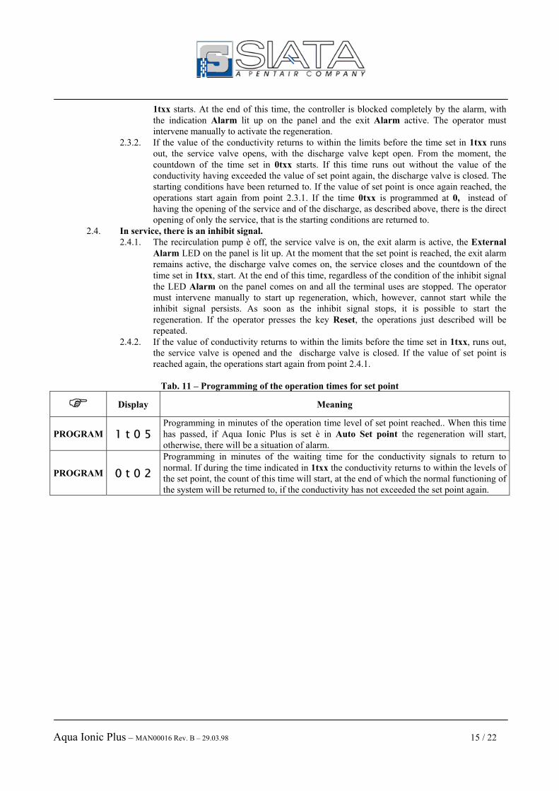
1txx starts. At the end of this time, the controller is blocked completely by the alarm, with the indication Alarm lit up on the panel and the exit Alarm active. The operator must intervene manually to activate the regeneration.
2.3.2. If the value of the conductivity returns to within the limits before the time set in 1txx runs out, the service valve opens, with the discharge valve kept open. From the moment, the countdown of the time set in 0txx starts. If this time runs out without the value of the conductivity having exceeded the value of set point again, the discharge valve is closed. The starting conditions have been returned to. If the value of set point is once again reached, the operations start again from point 2.3.1. If the time 0txx is programmed at 0, instead of having the opening of the service and of the discharge, as described above, there is the direct opening of only the service, that is the starting conditions are returned to.
2.4. In service, there is an inhibit signal. 2.4.1. The recirculation pump è off, the service valve is on, the exit alarm is active, the External
Alarm LED on the panel is lit up. At the moment that the set point is reached, the exit alarm remains active, the discharge valve comes on, the service closes and the countdown of the time set in 1txx, start. At the end of this time, regardless of the condition of the inhibit signal the LED Alarm on the panel comes on and all the terminal uses are stopped. The operator must intervene manually to start up regeneration, which, however, cannot start while the inhibit signal persists. As soon as the inhibit signal stops, it is possible to start the regeneration. If the operator presses the key Reset, the operations just described will be repeated.
2.4.2. If the value of conductivity returns to within the limits before the time set in 1txx, runs out, the service valve is opened and the discharge valve is closed. If the value of set point is reached again, the operations start again from point 2.4.1.
Tab. 11 – Programming of the operation times for set point
Display Meaning
PROGRAM 1 t 0 5 Programming in minutes of the operation time level of set point reached.. When this time has passed, if Aqua Ionic Plus is set è in Auto Set point the regeneration will start, otherwise, there will be a situation of alarm.
PROGRAM 0 t 0 2 Programming in minutes of the waiting time for the conductivity signals to return to normal. If during the time indicated in 1txx the conductivity returns to within the levels of the set point, the count of this time will start, at the end of which the normal functioning of the system will be returned to, if the conductivity has not exceeded the set point again.

Aqua Ionic Plus – MAN00016 Rev. B – 29.03.98 16 / 22
6.2.5 – SC03 - Resetting of the scale of the conductivity probe and of the value of set point. With this code of programming the scale of the conductivity probe can be set out of two types. The first goes 0.1 to 250 µS (--t1) and the second goes from 1 to 2500 µS (--t2). Once this has been set, it is possible to programme the value of the set point. This may be defined as the maximum value of conductivity above which the water produced is considered to be of very poor quality and it is therefore necessary to proceed to the regeneration of the resins. It is recommended that shielded cable is always used for the connection of the probe to the controller. The shielding must be grounded to the controller on terminal 65. This must not be confused with the grounding of the supply tension available to the terminals 5 and 6. If the distance between the probe and the controller is small ( less than 1 metre ), as an alternative to the shielded cable it is possible to use the “twisted” cable, the wires of which form a plait inside the external sheath ( as with a telephone wire). It is also advisable not to wire the probe wire in the immediate vicinity of the power or use lines.
Tab. 12 – Programming of the scale of the probe and the value of set point
Display Meaning
PROGRAM - - t 1 Programming of the scale of the probe of conductivity from 0.1 a 250 µS. ADVANCE - - t 2 Programming of the scale of the probe of conductivity from 1 a 2500 µS. PROGRAM 0.1.0.0 Programming of the value of set point 6.2.6 – SC04 – Resetting of the volume and of the counter divider. With this code of programming it is possible to set the value of the volume of water available and the value of the counter divider. The volume may be programmed with values from 1 to 10000 litres, and the divider can go from 1 to 100 impulses / litre. The programming of these parameters is functional only when the operative modality indicated by the LEDs on the panel includes the mode AutoVolume.
Tab. 13 – Programming of the treatable volume and of the counter divider
Display Meaning
PROGRAM x x x x Programming of the volume of treatable water. PROGRAM A A 1 4 Programming of the value of the litre counter divider (prescaler).

Aqua Ionic Plus – MAN00016 Rev. B – 29.03.98 17 / 22
6.2.7 – SC05 - Selection of the control modality for the start-up of the regeneration . With this code it is possible to select the control modality for the start-up of the regeneration from the following possibilities:
Tab. 14 – Operative modalities per the control of the start-up of the regeneration cycle
Display Meaning
PROGRAM t t 0 1 AutoVolume. The regeneration is activated from the control on the volume, which is decreased by the impulses coming from the litre counter sensor divided by the value programmed into the divider via the code SC04. As soon as the volume available reaches the value 0, the regeneration will be carried out, unless an inhibit signal is present.
ADVANCE t t 0 2 AutoSetPoint. The regeneration is activated by the control on the conductivity, which must exceed the value of Set point, set with the code SC03, for the time 1txx set with the code SC02. When the time indicated has run out, the regeneration will be carried out, unless there is an inhibit signal.
ADVANCE t t 0 3
AutoVolume + Manual. As with the AutoVolume mode, Aqua Ionic Plus carries out the controls on the volume of water available in order to carry out a regeneration. The presence of the option Manual ensures that the regeneration cannot be carried out automatically. As soon as the volume reaches 0, Aqua Ionic Plus enters into alarm mode, activating the relative exit to which a siren may be attached., blocking the system. When the operator hears the alarm, he must start up the regeneration manually. This cannot take place if there is an inhibit signal.
ADVANCE t t 0 4
AutoSetPoint + Manual. As with the AutoSetPoint mode, Aqua Ionic Plus carried out the controls on the value of conductivity of the water produced, in order to carry out a regeneration. The presence of the option Manual ensures that the regeneration cannot be carried out automatically. As soon as the value of conductivity exceeds the value of Set point for the time programmed , Aqua Ionic Plus enters into alarm mode, activating the relative exit to which a siren may be attached, blocking the system. When the operator hears the alarm, he must start up the regeneration manually. This cannot take place if there is an inhibit signal.
ADVANCE t t 0 5
AutoVolume + AutoSetPoint. In this operative modality, Aqua Ionic Plus controls both the volume of water available, and its quality at the same time, and carries out the regeneration when one of the two parameters reaches the conditions set for this, that is the volume available at 0 or the value conductivity above the value of set point for the time set, unless there is an inhibit signal.
ADVANCE t t 0 6
AutoVolume + AutoSetPoint + Manual. As in the above case, Aqua Ionic Plus controls the volume available and the quality of the water at the same time. When one of the two parameters reaches the conditions set for the start up of the regeneration, the alarm is activated and the system is blocked and Aqua Ionic Plus will await the intervention of the operator, who must start up the regeneration manually. This cannot take place if there is an inhibit signal..

Aqua Ionic Plus – MAN00016 Rev. B – 29.03.98 18 / 22
6.2.8 – SC06 - Selection of the SuperAutomatico modality. When Aqua Ionic Plus is programmed in Auto Set Point, the regeneration is started when the conductivity read by the probe exceeds the value of set point. If, for any reason the regeneration cannot be successful, the controller will start a series of chain regenerations caused by the fact that the conductivity will always exceed the value of set point. To avoid this happening, it is possible to enable the SuperAutomatico modality. During the last phase of the cycle, the value of conductivity read by the probe is compared to the value of set point which has been set. If the conductivity is lower than set point for at least one minute, the remaining time of the rinse is returned to zero, in order not to consume water and the cycle will finish. If, on the other hand, the value of the conductivity remains above the value of the set point for the entire duration of the last phase of the cycle, the signal Internal alarm is activated and each successive start-up of the regeneration, including manual start-ups, is blocked. IMPORTANT !! In order to be able to make the best use of the potential of this function, it is necessary to install the head of the probe in the low anode column 6.2.9 – SC07 – Setting of the access code. This allows for Aqua Ionic Plus to be protected against unauthorised access, preventing the programming codes from being accessed. The protection is active when a number different from 0000 is programmed, preventing access to the programming functions, as shown in tab. 4. To disables the protection code, it is sufficient to programme the code 0000 again. IMPORTANT ! If the code is forgotten, it is not possible to access the programming functions. In this event, please refer to the SIATA technical service. 6.2.10 – SC08 – Use of the recirculation pump. This code is used to programme the controller in such a way as to have the recirculation pump available on the terminals 7 and 8, with the repeat on terminals 41 and 42, turned off (00) or turned on (01) during the service. In this code, values from 00 to 03 may be programmed. The meaning of these values is as follows :
00 In case of conductivity lower than the value of set point: When there is no demand for water, the recirculation pump is on and the service electro valve is closed. When demand for water arrives, the pump is turned off and the service electro valve opens. In case of conductivity which exceeds the value of set point: When there is no demand for water, the recirculation pump is on, the service electro valve is off and the discharge is open. When there is demand for water, the recirculation pump and the service electro valve remain closed and the discharge is open.
01 In case of conductivity lower than the value of set point: When there is no demand for water, the recirculation pump is on and the service electro valve is closed. When demand for water arrives, the pump remains turned on and the service electro valve opens. In case of conductivity which exceeds the value of set point: When there is no demand for water, the recirculation pump is on, the service electro valve is off and the discharge is open. When there is demand for water, the situation just described remains unchanged.
02 Do not use. All the uses are always off..

Aqua Ionic Plus – MAN00016 Rev. B – 29.03.98 19 / 22
03 Do not use. All the uses are always off. 6.2.11 – SC09 – Resetting of the volume value. The volume value set with the code SC04 is decreased during the service by the counter which may be connected. This volume value is automatically reset at the end of the regeneration cycle. If the volume value is to be reset without having carried out a regeneration, it is sufficient to digit the code SC09 which carries out this operation. 6.3 – Remote Start Aqua Ionic Plus makes a “remote start ” available, which allows the regeneration to be started by an external automatism or by a button which could be installed at a distance from the system. Whichever device is used, this must be of a normally open, type, and to start the regeneration it must be closed for at least 15 seconds. 6.4 – Putting into service IMPORTANT Aqua Ionic Plus allows several operations to be carried out on the keypad, even if the rune ends are open. It is therefore possible to carry out programming operations at any time. The presence of the run ends ( whether the distributors are connected or whether the terminals are closed with bridges) is obligatory when Aqua Ionic Plus is to be put into service. During the service, the impulses coming from the litre counter sensor decrease the volume available via the divider set with the programming code SC04.

Aqua Ionic Plus – MAN00016 Rev. B – 29.03.98 20 / 22
7 – What to do if… Some basic operations for the resolution of small problems which may arise during the use of Aqua Ionic Plus are described below. If the suggestions shown do not help to resolve the situation, please call the SIATA service assistance. 7.1 - ... Aqua Ionic Plus does not come on ? 1. Check that the plug is correctly inserted in the electricity socket; 2. Check that the socket is correctly supplied; 3. Check that the adapter used does actually supply 24 Vac; 4. Check that the current conductors are corrected inserted into the terminals and that these are closed correctly. 5. Check that the fuse positioned on the panel has not blown. This fuse must be of delayed 1.6A; 7.2 - ... the motors of the distributors do not stop ? 1. Check that the run end wires of the distributors, marked 96-S, are correctly inserted in the terminals and that these
are closed correctly; 7.3 - ... there is no current to the utilisers? 1. Remember that Aqua Ionic Plus does not supply current to the exits, but only to closures that the operator must
wire at his own discretion, check that the wiring is correct, that the conductors are correctly inserted into the terminals and that these are closed correctly;
7.4 - ... Aqua Ionic Plus works in an irregular way? 1. Check that the distributors are at the stroke end, that is that the motors are not in movement; 2. If using Aqua Ionic Plus with a single distributor, check that the limit switch entry not used is closed with a
bridge; 7.5 - ... the reading of the conductivity is incorrect? 1. If not already used, substitute the probe connection cable with a shielded cable. 2. If using a shielded cable, check that the shielding sheath is correctly connected to ground, for example using the
pin 65 of the terminal. 3. If the cable of the probe runs near to power devices (like for example the remote switch or the pumps) try to move
the route of the cable to some distance away from the above components.
Aqua Ionic Plus – MAN00016 Rev. B – 29.03.98 21 / 22
Attachment A

Aqua Ionic Plus – MAN00016 Rev. B – 29.03.98 22 / 22
Attachment B