Embed Size (px)
Citation preview
ALS 423 TXALS 333 CALS 433 CALS 433 TXAIRLESS UNITS
Use and Maintenance Instruction ManualEN
2
CONTENTS
USE OF THE MANUAL .................................................................................................................. 3 WARRANTY ................................................................................................................................... 3
1. SAFETY PRECAUTIONS ............................................................................................................... 42. TRANSPORT AND HANDLING ..................................................................................................... 62.1 TRANSPORT ................................................................................................................................... 62.2 TRANSPORT WITH CARDBOARD PACKING ................................................................................ 62.3 HANDLING ...................................................................................................................................... 62.4 CHECK ON THE PURCHASED PRODUCT .................................................................................... 72.5 TEMPORARY STORAGE ................................................................................................................ 73. PRODUCT IDENTIFICATION ........................................................................................................ 83.1 PRODUCT SPECIFICATIONS ......................................................................................................... 83.2 TECHNICAL SPECIFICATIONS ...................................................................................................... 83.3 PLATE DATA ................................................................................................................................... 93.4 COMPLIANCE TO THE STANDARDS ............................................................................................. 93.5 SAFETY SYSTEMS ....................................................................................................................... 103.6 WORKABLE PRODUCTS .............................................................................................................. 114. OPERATION ................................................................................................................................. 124.1 OPERATION DESCRIPTION ......................................................................................................... 125. INSTALLATION AND STARTING-UP ......................................................................................... 135.1 CONDITIONS FOR INSTALLATION .............................................................................................. 135.2 INSTALLATION ............................................................................................................................. 136. USE .......................................................................................................................................... 156.1 USE .......................................................................................................................................... 156.2 SAFETY RULES DURING USE ..................................................................................................... 156.3 CLOTHES ...................................................................................................................................... 156.4 UPPER GASKETS PREWASH AND ADJUSTMENT ..................................................................... 166.5 STARTING-UP .............................................................................................................................. 166.6 DAILY INTERRUPTIONS ............................................................................................................... 176.7 WRONG AND DANGEROUS USES .............................................................................................. 186.8 PRESSURE RELEASE PROCESS ................................................................................................ 197. MAINTENANCE AND INSPECTION ........................................................................................... 197.1 GENERAL NOTES ......................................................................................................................... 197.2 SAFETY RULES DURING MAINTENANCE ................................................................................... 197.3 RECOMMENDED SCHEDULED OPERATIONS ........................................................................... 197.4 DISASSEMBLY AND RE-ASSEMBLY PROCEDURE ................................................................... 207.5 MOTOR GROUP DISASSEMBLY ................................................................................................. 207.6 MOTOR GROUP MAINTENANCE ................................................................................................. 207.7 MOTOR GROUP RE-ASSEMBLY ................................................................................................. 217.8 PNEUMATIC MOTOR DISASSEMBLY FROM THE PUMP ROD .................................................. 217.9 PUMP ROD DISASSEMBLY ......................................................................................................... 227.10 PUMP ROD MAINTENANCE ........................................................................................................ 227.11 PUMP ROD RE-ASSEMBLY ......................................................................................................... 227.12 MOTOR GROUP RE-ASSEMBLY TO THE PUMP ROD ............................................................... 237.13 TESTS TO BE CARRIED OUT AFTER RE-ASSEMBLY ................................................................ 237.14 PAINT FILTER MAINTENANCE ..................................................................................................... 238. SPARE PART LISTS .................................................................................................................... 248.1 ALS UNITS SPARE PARTS LIST ................................................................................................... 248.2 EXPLODED VIEW .......................................................................................................................... 259. ACCESSORIES ............................................................................................................................ 269.1 ALS UNITS ACCESSORIES .......................................................................................................... 269.2 DELIVERY FILTER TF-8 ................................................................................................................ 279.3 DELIVERY FILTER TF-8N ............................................................................................................. 279.4 AIR REGULATOR UNIT for ALS 333-C .......................................................................................... 279.5 AIR REGULATOR UNIT for ALS 433-C / ALS 433-TX / ALS 423-TX ............................................... 289.6 DIP TUBE WITH FILTER ............................................................................................................... 289.7 SUCTION COVER ......................................................................................................................... 2810. TROUBLESHOOTING .................................................................................................................. 2911. DISMANTLING ............................................................................................................................. 3111.1 EQUIPMENT STORAGE ............................................................................................................... 3111.2 DISMANTLING .............................................................................................................................. 31
3
USE OF THE The use and maintenance manual is the document accompanying the equipment from its manufactu-
MANUAL re till its dismantling. Therefore, it is an integral part of the equipment.
The manual must be read before starting ANY ACTIVITY involving the equipment including its hand-
ling.
WARNING THE ORIGINAL CONFIGURATION OF THE EQUIPMENT MUST NOT BE CHANGED AT ALL.
On receiving the equipment check that:
The supply corresponds to the order specifications.
In case of non-compliance, inform immediately our TECHNICAL SERVICES. WARNING ALL RIGHTS ARE RESERVED. THE REPRODUCTION OF ANY PART OF THIS MANUAL, IN ANY FORM, IS STRICTLY FORBIDDEN WITHOUT PRIOR WRITTEN AUTHORIZATION OF THE MANUFACTURING COMPANY.
WARRANTY All ANEST IWATA products have a one-year guarantee from the invoice date, unless otherwise stated in writing. The warranty covers all manufacturing faults and material defects. Any spare part replace- ment or repair operations are covered only if they are carried out by our technicians at our servicing shops.
The faulty parts must be sent CARRIAGE PAID. Once the components have been repaired, they will be sent CARRIAGE FORWARD to the customer.
The warranty covers no intervention of our technicians during installation or dismantling operations. If for practical purposes one of our technicians is sent on site, a charge will be made for the time plus extra for travelling and expenses.
Our warranty does not cover direct or indirect damage to people or property caused by our equiment. It covers no repair operations carried out by the customer or by a third party, either.
THE WARRANTY DOES NOT COVER:
- Damage or breakdown caused by improper use or assembly.
- Damage or breakdown caused by the use of spare parts that are different from the original or recommended ones.
- Damage or breakdown caused by a bad preservation.
- Components subject to wear (described in the spare part list).
WARRANTY FORFEITURE:
- In case of delayed payment or other contractual defaults.
- Whenever changes or repairs are carried out on our equipment without prior authorization.
- Whenever the serial number is damaged or removed.
- When the damage is caused by improper use or functioning, or if the equipment falls, is bumped or by other causes not due to the normal working conditions.
- Whenever the unit is disassembled, tampered with or repaired without the authorization of ANEST IWATA.
All repair interventions carried out under warranty do not interrupt its duration. All disputes will be settled in the court of justice of Turin.

4
1. SAFETY PRECAUTIONS
• Be sure to read and understand this instruction manual. The operator shall be fully conver sant with the requirements stated within this instruction manual including important warnings, cautions and operations. • Wrong operation (mishandling) can cause serious bodily injury, death, fire or explosion.
SAFETY FACTOR
• Pay special attention to items which are shown by the below marks and symbols.
WEAR PROTECTIVE GEAR During painting, be sure to wear protective gear such as glasses, mask or gloves to avoid serious injury caused by paints or solvents which might enter your eyes or you might inhale.
BE CAREFUL ABOUT VENTILATION
Use it in a well-ventilated area. Painting or cleaning in a narrow area with insufficient ventilation can cause organic solvent intoxication or explosion due to sprayed mist of paint or solvent which catches fire. If you feel any abnormality during operation, consult a medical doctor immediately.
CONTACT IS FORBIDDEN
If paint leaks, never try to stop it by hand. In that case please proceede as follows:
In the case you feel any abnormality, please proceed as follows:
1. Follow the instructions about relaese pressure procedure, provided in section 6.8.
2. Check the leackage causes.
3. Replace or repair the faulty component.
BE CAREFUL ABOUT BODILY INJURY
Paint can enter human body directly through eyes, mouth or skin. It is very dangerous. If you feel any abnormality or receive any injury, consult a medical doctor immediately.
LIMIT OF FLUID TO BE USED
Do not use it for food products. KEEP AWAY FROM ORIGINS OF EXPLOSIONS OR FIRES
Never use near sparks or open fire. Especially the following will cause fire • Open flames such as cigarettes, pipes. • Electric goods such as stoves, lamps or heates.
5
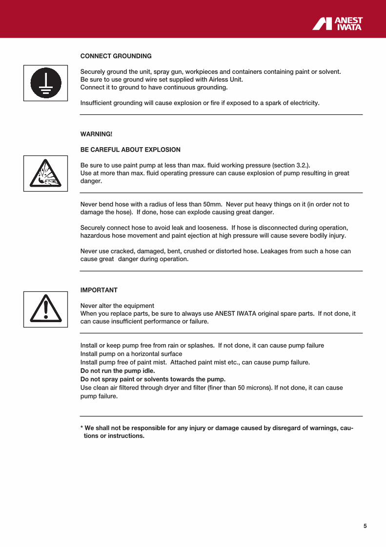
CONNECT GROUNDING
Securely ground the unit, spray gun, workpieces and containers containing paint or solvent. Be sure to use ground wire set supplied with Airless Unit. Connect it to ground to have continuous grounding.
Insufficient grounding will cause explosion or fire if exposed to a spark of electricity.
WARNING!
BE CAREFUL ABOUT EXPLOSION Be sure to use paint pump at less than max. fluid working pressure (section 3.2.). Use at more than max. fluid operating pressure can cause explosion of pump resulting in great danger. Never bend hose with a radius of less than 50mm. Never put heavy things on it (in order not to damage the hose). If done, hose can explode causing great danger. Securely connect hose to avoid leak and looseness. If hose is disconnected during operation, hazardous hose movement and paint ejection at high pressure will cause severe bodily injury. Never use cracked, damaged, bent, crushed or distorted hose. Leakages from such a hose can cause great danger during operation.
IMPORTANT Never alter the equipment When you replace parts, be sure to always use ANEST IWATA original spare parts. If not done, it can cause insufficient performance or failure. Install or keep pump free from rain or splashes. If not done, it can cause pump failure Install pump on a horizontal surface Install pump free of paint mist. Attached paint mist etc., can cause pump failure. Do not run the pump idle. Do not spray paint or solvents towards the pump. Use clean air filtered through dryer and filter (finer than 50 microns). If not done, it can cause pump failure.
* We shall not be responsible for any injury or damage caused by disregard of warnings, cau- tions or instructions.

6
2. TRANSPORT AND HANDLING
2.1 TRANSPORT To transport the equipment only the systems described below can be used. In any case make sure that the transport and lifting device can bear the weight of the equipment with its packaging.
WARNING ALWAYS KEEP THE PACKAGING IN VERTICAL POSITION.
WARNING IT IS ADVISABLE THAT THE STAFF IN CHARGE OF HANDLING THE EQUIPMENT WEAR PROTECTIVE GLOVES AND SAFETY SHOES.
WARNING WHILE LIFTING OR HANDLING THE EQUIPMENT OR ANY OF ITS COMPONENTS CLEAR THE WORKING AREA. LEAVE ALSO A SUFFICIENT SAFETY AREA AROUND THE EQUIPMENT TO AVOID DAMAGING PEOPLE OR OBJECTS WHICH COULD BE THERE.
2.2 TRANSPORT WITH CARDBOARD PACKAGING The equipment is put inside a cardboard packaging and wrapped with some shockproof material.
2.3 HANDLING To handle the cardboard packaging use a trolley.
WARNING FOLLOW THE INSTRUCTIONS ON THE PACKAGING BEFORE HANDLING AND OPENING IT.
HANDLING BY MEANS OF HANDLE HANDLING BY MEANS OF TROLLEY

7
2.4 CHECK ON THE PURCHASED PRODUCT
When you receive and before using the pump, make sure it has not been damaged during tran
sport or storage. Also check that all standard components are inside the packaging.
2.5 TEMPORARY STORAGE
During transport and storage make sure the temperatures between 0 and 40° C are not exceeded. In case of storage, make sure the equipment is not put in places with an excessive humidity.

8
3.2 TECHNICAL SPECIFICATIONS
3. PRODUCT IDENTIFICATIONS
3.1 PRODUCT SPECIFICATIONS
MODELS ALS-333 C ALS-433 C ALS-433 TX ALS-423 TX
Pump unit PP1251 C PP4301 C PP4301 CNE PP4231 NE
Dimensions (mm) 500x500x900 500x500x970
Weight 23 kg 30 kg 30 kg 35 kg
Air nipple G 1/4”
Fluid nipple G 1/4”
Delivery paint filter TF-8 TF-8 TF-8N TF-8N
Dip tube filter 50 mesh 50 mesh 30 mesh 30 mesh
Max. working air pressure 6.8 bar
Compression ratio 25:1 30:1 30:1 23:1
Max. fluid output 2.5 l/min 5.0 l/min 5.0 l/min 8.0 l/min
Delivery/cycle ~ 26 ml/cycle ~ 59 ml/cycle ~ 59 ml/cycle ~ 80 ml/cycle
Max. No. of cycles per minute 90 cyc/min. 90 cyc/min. 90 cyc/min. 100 cyc/min.
Cycle stroke 58 mm 93 mm 93 mm 93 mm
Compressor (required power) > di 0.75 Kw > di 1.5 Kw > di 1.5 Kw > di 1.5 Kw
Working temperature 5~40 °C
Noise level 84.1 dB(A)* 78.1 dB(A)* 78.1 dB(A)* 78.1 dB(A)*
ALS-3
33
C ALS-333 C: STANDARD Version
Pump unit PP1251 C mounted on cart, with air regulator, dip tube with filter, delivery paint filter unit, fluid recirculation hose, overpressure valve.
ALS-4
33
C ALS-433 C: STANDARD Version
Pump unit PP4301 C mounted on cart, with air regulator, dip tube with filter, delivery paint filter unit, fluid recirculation hose, overpressure valve.
ALS-4
33
TX
ALS-433 TX: WATER BASE PAINT Version
Pump unit PP4301 CNE mounted on cart, with air regulator, dip tube with filter, deli-very paint filter unit, fluid recirculation hose, overpressure valve. Paint passages in Stainless Steel.
ALS-4
23
TX
ALS-423 TX: WATER BASE PAINT Version
Pump unit PP4231 NE mounted on cart, with air regulator, dip tube with filter, deliverypaint filter unit, fluid recirculation hose, overpressure valve. Paint passages in Stainless Steel.
9
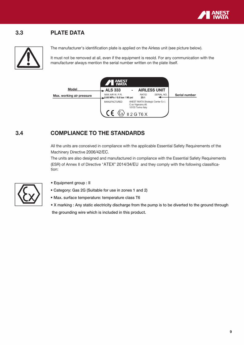
3.3 PLATE DATA
The manufacturer’s identification plate is applied on the Airless unit (see picture below).
It must not be removed at all, even if the equipment is resold. For any communication with the manufacturer always mention the serial number written on the plate itself.
3.4 COMPLIANCE TO THE STANDARDS
All the units are conceived in compliance with the applicable Essential Safety Requirements of the
Machinery Directive 2006/42/EC. The units are also designed and manufactured in compliance with the Essential Safety Requirements
(ESR) of Annex II of Directive "ATEX" 2014/34/EU and they comply with the following classifica- tion:
• Equipment group : II
• Category: Gas 2G (Suitable for use in zones 1 and 2)
• Max. surface temperature: temperature class T6
• X marking : Any static electricity discharge from the pump is to be diverted to the ground through
the grounding wire which is included in this product.
MAX AIR W. P.R. RATIO SERIAL NO. 0.68 MPa / 6.8 bar / 98 psi 25:1
MANUFACTURED
ALS 333 - AIRLESS UNIT
ANEST IWATA Strategic Center S.r.l.C.so Vigevano,4610155 Torino Italy
Serial number
Model
Max. working air pressure

10
3.5 SAFETY SYSTEM
Several safety systems have been conceived during the Airless unit design and manufacture to safeguard the operator, as it prescribed by all applicable safety regulations.
SAFETY INFORMATION In case of units that are to be used in areas with potentially explosive atmospheres, before starting working the operators must disable the unit power supply, by putting it “out of order”. They also must ensure that the unit cannot be restarted unintentionally.
All further necessary environmental safety measures must be adopted (such as the elimination of gas or residual dusts, etc.).
SAFETY VALVE
A 8 bar calibrated safety valve is installed to ensure the pump working pressure does not exceed the limits inside the feeding circuit. If the calibration pressure is exceeded, the valve opens by releasing the excess of air.
WARNING
DO NOT REMOVE THE VALVE PLASTIC PROTECTION. ANY TAMPERING WITH COULD BE DANGEROUS FOR THE OPERATOR AND COMPROMISE THE EQUIPMENT GOOD WORKING.
BALL VALVE
In case of anomalies during working, turn 90° the ball valve lever. In this way the air supply will be interrupted and the residual pressure inside the pump will be released.

11
SAFETY PICTOGRAMS Some pictograms can be found on the pump with the safety warnings to follow by anyone who is going to use it.
WARNING THE MANUFACTURING COMPANY IS NOT TO BE HELD RESPONSIBLE FOR DAMAGE OR ACCIDENTS TO PEOPLE OR THINGS COMING FROM THE NON-COMPLIANCE WITH THE PRESCRIBED RULES.THE RESPONSIBILITY RESTS ENTIRELY WITH THE OPERATOR HIM SELF.
3.6 WORKABLE PRODUCTS
All Airless Units ANEST IWATA are conceived to paint ferrous material in general, wood and plastic. Models ALS 333 C and ALS 433 C are designed for paints with a maximum viscosity of 85 sec/Ford #4 (100 sec/NK-2). We don't recommend the use of these models with water-based paints. Models ALS 423 TX and ALS 433 TX are intended also for high viscosity and water-based paints. To use the equipment with special products ask for the approval of the manufacturer. Moreover, the technical features of the unit must be adapted for processing such products. ANEST IWATA is not liable for any accident due to UNAUTHORISED and non qualified personnel using the pump or personnel using it for purposes that are different from the above-mentioned ones.
WARNING DO NOT USE: - ANY HALOGENATED HYDROCARBON SOLVENTS, SUCH AS TRICHLOROETHANE, METHYLENE CHLORIDE OR SOMETHING LIKE THAT; - ANY TOXIC PRODUCTS SUCH AS PETROL, KEROSENE OR COMBUSTIBLE GASES; - ANY HERBICIDE OR PESTICIDE - ANY RADIOACTIVE FLUID
12
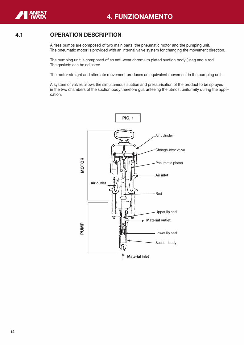
4.1 OPERATION DESCRIPTION
Airless pumps are composed of two main parts: the pneumatic motor and the pumping unit. The pneumatic motor is provided with an internal valve system for changing the movement direction.
The pumping unit is composed of an anti-wear chromium plated suction body (liner) and a rod. The gaskets can be adjusted.
The motor straight and alternate movement produces an equivalent movement in the pumping unit.
A system of valves allows the simultaneous suction and pressurisation of the product to be sprayed, in the two chambers of the suction body,therefore guaranteeing the utmost uniformity during the appli- cation.
4. FUNZIONAMENTO
MO
TOR
P
UM
P
Air cylinder
Change-over valve
Pneumatic piston
Air inlet
Rod
Upper lip seal
Material outlet
Lower lip seal
Suction body
Material inlet
Air outlet
PIC. 1
13
5.1 CONDITION FOR INSTALLATION
• The installer must know the ATEX classification of the installation area, as well as the risks coming
from a potentially explosive atmosphere, by paying attention to the explosion and fire risks so as to
adopt the most suitable protections.
• All maintenance, assembly and disassembly operations must be carried out by a qualified staff
outside the area at risk of explosion.
• Also check that the accessories comply with the essential safety requirements of the ATEX direc-
tives. Handle them with great care to avoid changing their features.
• Once installed, clean the unit.
• Use antistatic hoses for connection of Airless Unit and spray gun. The equipment must be installed by a specialized and authorized staff. In any case, follow the instructions below. Painting must preferably take place inside a suitable spray booth equipped with suction device. Do not use the unit if the suction device is off.
WARNING IF PAINTING IS CARRIED OUT OUTSIDE THE SPRAY BOOTH, ALWAYS OPERATE IN A PLACE WITH A RIGHT VENTILATION TO AVOID CONCENTRATING INFLAMMABLE VAPOURS COMING FROM SOLVENTS OR PAINTS.
5.2 INSTALLATION - Place the equipment on the floor, on a horizontal surface. - Secure it firmly to the ground by means of the trolley fastening bracket (pic.2 on page 14). - Connect the dip tube steadily (pos. A in pic. 2 on page 14) and the recirculation hose (pos. B in pic. 2
on page 14). - Connect the high pressure hose for paint to the delivery paint filter. - Earth the free end of the ground cable directly. - Connect the Airless gun to the other end of the air/paint twin hose. - Connect the air supply hose to the unit.
WARNING
- CHECK THE PROPER TIGHTENING OF ALL FITTINGS, SINCE THEIR SUDDEN OPENING CAN SERIOUSLY INJURE PEOPLE.
WARNING
- CONSULT THE LOCAL CODE FOR DETAILED INSTRUCTIONS RELATIVE TO GROUND CON- NECTIONS IN THE WORK AREA AND TO THE TYPE OF SYSTEM USED.
- THE GROUND CABLE (INCLUDED IN THE SUPPLY) MUST HAVE A MINIMUM SECTION EQUAL TO 1.5 mm2.
- ONE END OF THE CABLE MUST BE EARTHEN WHILE THE OTHER MUST BE CONNECTED TO THE LID OF THE PNEUMATIC MOTOR SILENCER.
5. INSTALLATION AND STARTING

14
INSTALLATION SCHEME
PAINT OUT-LET
RECIRCULATION VALVE (C)
UPPER GASKETS ADJUSTING CUP (D)
MATERIAL RECIR-CULATION HOSE (B)
TROLLEY FASTENING BRACKET
AIR INLET
PAINT INLET
GROUND CABLE
SUCTION HOSE
SAFETY SPRING
PIC. 2

15
6. USE
6.1 USE
This section describes the Airless Unit use in compliance with the safety standards in force. Read this section carefully. LIMITS AND CONDITIONS OF USE Any modification to the constructive shape or to the assembling position is allowed only after asking for ANEST IWATA technical service authorization. If there is no authorization the ATEX approval in no longer valid.
ENVIRONMENTAL CONDITIONS Room temperature: min. + 5°C; max. +40°C
The plate data of the maximum superficial temperatures refer to measures taken in normal environ- mental conditions and to a normal installation. Any minimum variation of these conditions can greatly affect the heat development.
6.2 SAFETY RULES DURING USE
TO USE the Airless Unit COMPLY WITH the safety precautions and rules described below.
The manufacturing company declines all responsibility if the operator does not comply with them. It is not to be held responsible for any carelessness during the pump use, either. - If the system is used improperly, it could be broken by causing serious damage.
- Use the Airless unit for professional purposes only.
- Do not change the system; use only Anest Iwata original spare parts.
- Check the system daily: repair or replace immediately all worn or damaged parts.
- Never exceed the maximum working pressure: 6.8 bar.
- IT IS FORBIDDEN to use the equipment for purposes that are different from the ones it is destined to which are described in the use and maintenance manual. If in doubt, apply to your Anest Iwata reseller. - Use paints and solvents compatible with the system parts they come in touch with.
- Refer to the paint and solvent features mentioned by the manufacturer.
- Wear the protective clothes described in section 6.3.
- Comply with all the local standards on electric safety and fire risks.
6.3 CLOTHES
Wear some protective gloves and goggles, an oxygen mask and some ear protections during working. In any case, follow the references of the current regulations.
16
6.4 PREWASH AND ADJUSTMENT OF UPPER PACKING
1. Make sure the pump has been properly installed; (see point 5.2)
2. Immerse dip tube (pos. 5 on page 26) in the cleaning liquid (clean solvent or water, according to the purchased model).
3. Place the ball valve (pos. 3-5 and 3-8 on page 27 and 28) in the proper position.
4. Open the recirculation valve (pos. C in pic. 2 on page 14) located on the paint filter.
5. Loosen the upper gaskets adjusting cup (pos. D in pic. 2 on page 14).
6. Gradually open the air pressure regulator up to the minimum pressure required for the straight and alternate movement of the pump (about 0.5 bar).
7. Adjust the upper gaskets by gradually tightening the adjusting cup (pos. D in pic. 2 on page 14) until stopping the cleaning liquid outflow, and the pump movement.
NOTE: The failure to observe this point as well as an improper initial adjustment of the gaskets might reduce their duration.
8. Once the gaskets have been adjusted, increase the air supply pressure (up to about 2 bar) and let the cleaning liquid flow in the recirculation hose for a few minutes.
9. Close the recirculation valve (pos. C in pic. 2 on page 14), clean the paint hose and the gun by keeping its trigger pulled.
10. Once you are sure the cleaning has been properly carried out, lift the dip tube from the vessel containing the cleaning liquid and let the residual liquid flow out of the gun first, and then from the recirculation hose.
WARNING THE PUMP MUST BE CLEANED BEFORE USING IT FOR THE FIRST TIME, IF IT IS NOT USED FOR A LONG TIME AND AFTER ANY COLOUR CHANGE.
6.5 STARTING UP
Before beginning working, start the pump by following the instructions below:
1. Dip the dip tube in the tank with the product to be pumped.
2. Open the two-way valve for paint recirculation (pos. C in pic. 2 on page 14).
3. Lift and gradually turn the pressure reducer knob (3-2 on page 27 and 28). Adjust it at a pressure slightly higher than 2.0 bar, to enable the pump to release the air.
4. Close the two-way valve for paint recirculation (pos. C in pic. 2 on page 14) and release the air through the gun, as well.
5. Increase the pressure of the reducer connected to the pump, according to the desired working pressure.

17
PRECAUTIONS a) Use Airless guns only.
b) When the paint level inside the tank decreases, the pump might suck some air. Increase the level of paint.
b) Do not drag the pump by pulling it by the hoses.
d) Do not spray towards the eyes or towards other people.
CAUTIONS: EMERGENCY STOP Whenever the pump must be stopped due to one of the following reasons:
a) The material never stops coming out of the gun
b) Fluid discharge through the connectors or the damaged hose. THEN, close the BALL VALVE (pos. 3-5 and 3-8 on page 27 and 28).
WARNING
a) When assembling or removing the gun nozzle, always bock the trigger by means of the safety catch.
b) Never remove the gun trigger safety catch.
c) Never exceed the maximum working pressure (6.8 bar).
d) Always use a Airless ANEST IWATA gun, which is provided with various safety devices.
e) During functioning, never touch the moving parts. Before carrying out any maintenance operation disconnect the air supply and discharge the residual pressure.
6.6 DAILY INTERRUPTIONS
1. Upon suspending the use of the pump:
- It is not necessary to disconnect the air supply if the interruption is short.
- If the interruption is long, turn the ball valve (pos. 3-5 and 3-8 on page 27 and 28), discharge the air from the circuit and open the recirculation valve (pos. C in pic. 2 on page 14) to release the residual fluid pressure.
2. When the pump is stopped at the end of the working day:
- Clean the fluid passages.
- Remove the dip tube filter, the filter inside the delivery paint filter and the gun filter, and clean them.
18
6.7 WRONG AND DANGEROUS USES
A wrong earthing, an insufficient ventilation, a naked flame or a spark can cause a fire or an explosion and provoke some serious injuries.
WARNING IF SOME SPARKS OR AN ELECTRIC DISCHARGE WERE PERCEIVED, INTERRUPT IMMEDIATELY ALL PAINTING OPERATIONS. DO NOT USE THE SYSTEM UNTIL THE PROBLEM CAUSE IS IDENTIFIED.
Keep away from the working area all kinds of waste, of solvent container, of solvent or petrol soaked rags or clothes.
Before starting the system disconnect all the electrical connections inside the working area.
Before using the system switch off all the naked flames and pilot lights inside the working area.
Do not smoke inside the working area.
During painting operations, or if there are some vapours in the air, do not switch on or off the lights inside the working area.
Do not use any petrol engine inside the working area.
Some organic solvents or discharged toxic vapours can enter the eyes or the skin, be swallowed or inhaled, by provoking serious injuries.
When the air engine is running, keep the face away from the exhaust.
6.8 PRESSURE RELEASE PROCESS WARNING 1. Close the air supply to the pump by turning the pressure reducer adjustment counter-clockwise
down to 0 bar.
2. Activate the safety catch of the Airless gun trigger.
3. Make sure the recirculation hose is not clogged, then gradually open the recirculation ball valve, and leave it open.
4. Hold the gun tightly and lean it against the metal vessel with the paint. Remove the safety catch of the Airless gun trigger, and gently pull the trigger to release the pressure inside the paint hose and inside the gun.
5. Block the Airless gun trigger once more by means of the safety catch.
6. If you believe the pressure has not been fully released by following the instructions provided in point 4, loosen the gun nozzle carrier to gradually release the residual pressure, then loosen it completely. Clean the fluid passage ducts.
19
7.1 GENERALS NOTE • Comply with the inspection and ordinary maintenance intervals so as to ensure suitable working conditions and explosion-proof protection. • Before carrying out any maintenance operation or repair on the internal parts, delay the opening of the unit and wait till it is completely cool to avoid any burning risk due to the presence of hot parts. • After the maintenance intervention, make sure that all the safety measures are completely and correctly restored. • Once the maintenance operations/repairs have come to an end, clean the whole unit. • Use only original spare parts for repairs.
A suitable maintenance is important for a longer duration of the equipment in good working condi- tions and efficiency ensuring functional safety as time goes by. All maintenance operations must be carried out by a qualified staff. The pump design and the mate- rials used to manufacture it limit the maintenance interventions to a simple periodic cleaning.
The staff must be provided with the individual protections that are generally used for similar opera- tions. They also must follow the safety rules described in section 7.2
7.2 SAFETY RULES DURING MAINTENANCE
Le principali attenzioni da adottare in occasione di interventi manutentivi sull’unità sono:
1. Disconnect the pneumatic supply before replacing any component.
2. Do not wear rings, watches, chains, bracelets, etc. during maintenance operations.
3. Always use the individual protections (gloves, safety shoes, etc.).
4. Do not use naked flames, points or pins for cleaning.
5. Do not smoke.
7.3 RECOMMENDED SCHEDULED OPERATIONS
Daily A. Clean the nozzle, the gun paint filter and the delivery filter.maintenance B. Clean all parts in touch with paint. C. Check the good-working order of the safety devices. Every 50 A. Clean the inside of the paint passage ducts, especially if highly pigmented paints o r paints withworking hours many particles tending to deposit are used. B. Clean the dip tube inlet filter.
Every 100 A. Clean the inside of the paint passage ducts, using a product able to remove all traces of depo-working hours sited paint.
Every 300 A. Inspect and tighten the lip seals of the pump motor.working hours
Every 500 A. Grease all motor and air cylinder sliding parts.working hours
Every 1000 A. Disassemble all components and clean them thoroughly.working hours B. Replace all worn out components.
7. MAINTENANCE AND INSPECTION
20
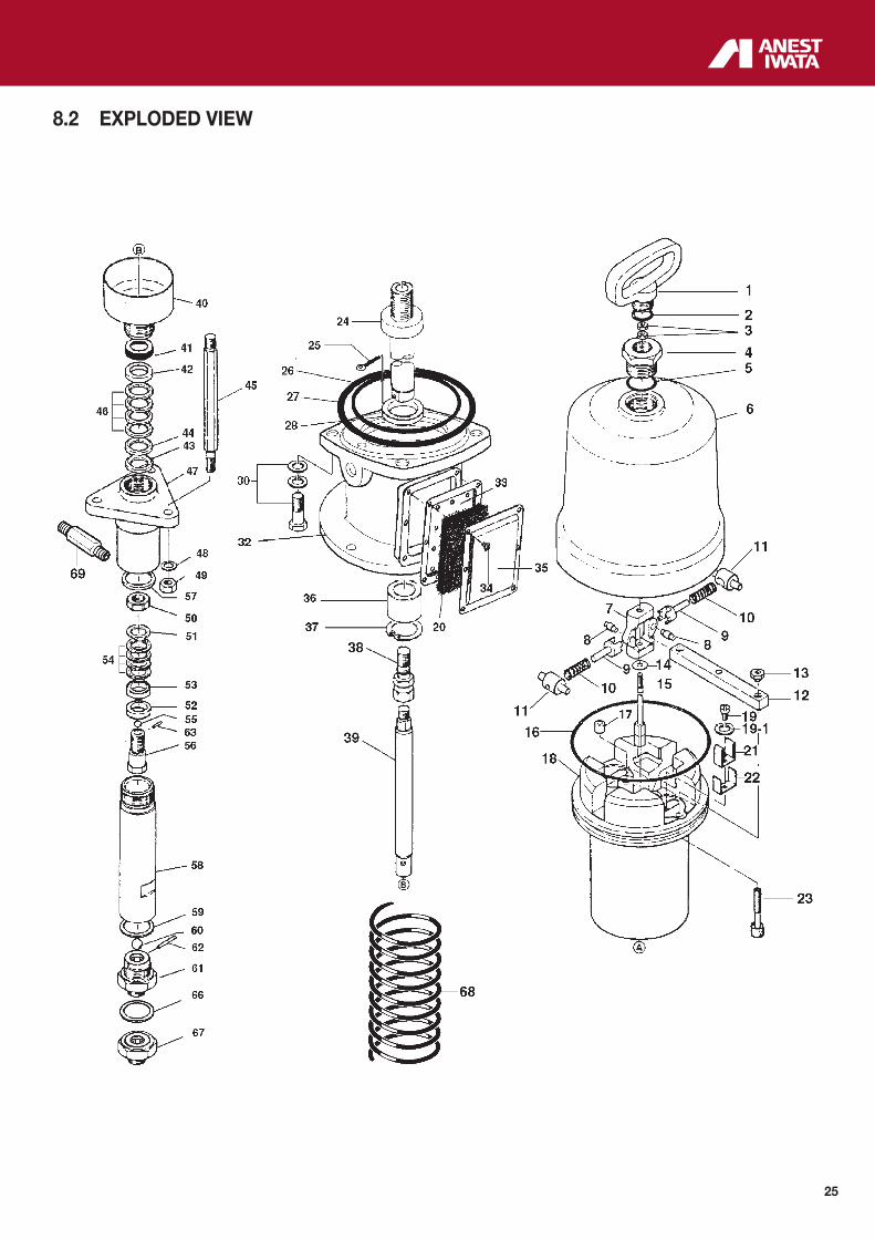
7.4 DISASSEMBLY AND RE-ASSEMBLY PROCEDURE WARNING BEFORE STARTING ANY MAINTENANCE OPERATION REMOVE THE AIR SUPPLY HOSE AND MAKE SURE THE INNER RESIDUAL PRESSURE HAS BEEN RELEASED. NOTE: The numbering of the follows components refers to the exploded view drawings of Airless Unit in chapter 8.0.
7.5 MOTOR DISASSEMBLY
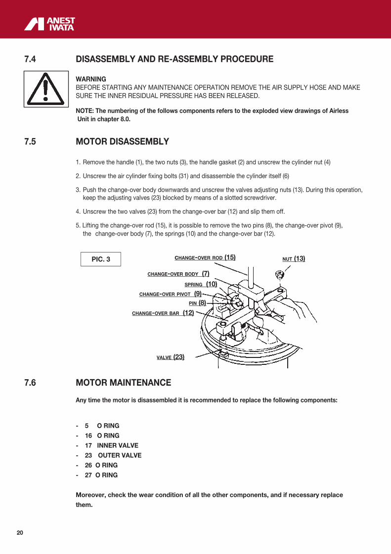
1. Remove the handle (1), the two nuts (3), the handle gasket (2) and unscrew the cylinder nut (4)
2. Unscrew the air cylinder fixing bolts (31) and disassemble the cylinder itself (6)
3. Push the change-over body downwards and unscrew the valves adjusting nuts (13). During this operation, keep the adjusting valves (23) blocked by means of a slotted screwdriver. 4. Unscrew the two valves (23) from the change-over bar (12) and slip them off.
5. Lifting the change-over rod (15), it is possible to remove the two pins (8), the change-over pivot (9), the change-over body (7), the springs (10) and the change-over bar (12).
7.6 MOTOR MAINTENANCE
Any time the motor is disassembled it is recommended to replace the following components:
- 5 O RING
- 16 O RING
- 17 INNER VALVE
- 23 OUTER VALVE
- 26 O RING
- 27 O RING
Moreover, check the wear condition of all the other components, and if necessary replace
them.
change-over rod (15)
change-over body (7)
spring (10)
nut (13)
change-over pivot (9)
change-over bar (12)
valve (23)
pin (8)
PIC. 3

21
7.7 MOTOR RE-ASSEMBLY Follow the above mentioned procedure in reverse order, bearing in mind the following points: 1. While assembling the valves (23), push the change-over body (7) downwards. Then, screw the valves to the change-over bar (12) and adjust the clearance between the sealing surfa-ces of the valves and of the piston (18), that must be equal to 2 mm for both.
2. Once adjusted, fasten the valves to the change-over bar by means of the two nuts (13), using some thread-brake to prevent subsequent unscrewing.
3. After carrying out the operations provided in chapter 7.6 check the clearance (2 mm) once more. 4. Grease all components with lithium based grease, caring not to obstruct the air passages.
5. Re-assemble the cylinder (6) and fasten it with the proper screws (31).
6. Lock the change-over rod (15) by means of the two nuts (3), as shown in the picture.
7.8 PNEUMATIC MOTOR DISASSEMBLY FROM THE PUMP ROD 1. Keep the rod (39) still and unscrew connecting adaptor (38), as shown in picture 6.
2. Loosen and undo the three nuts (49).
PIC. 4
PIC. 5change-over rod and nut at the same level.
motor base (32)
rod (39)
nut (49)
connectig adaptor (38)
PIC. 6
22
7.9 PUMP ROD DISASSEMBLY
1. Secure the suction main body (47), unscrew the suction tube (58) and slip it off.
2. Slip the rod (39) off from suction main body (47).
4. Loosen the adjustment nut (50) and unscrew the valve holder (56).
5. Remove the spacer, the adapters, the gaskets and the upper ball.
6. Unscrew the thinner cup (40) from the suction main body (47) and remove the spacer, the adapters and the gaskets.
7. Unscrew the lower valve (61) from the suction tube (58) and remove the ball.
7.10 PUMP ROD RE-ASSEMBLY
1. Dip all components in the cleaning liquid and thoroughly clean them.
2. Make sure the rod (39) and the suction tube (58) are not damaged. If they show deep scratches in the sli- ding areas, replace them.
3. Make sure the valve holder (56) and the lower valve (61) are not damaged, especially in the area in touch with the ball. If any anomaly is found, replace them.
4. Whenever the pumping unit is completely disassembled, it is advisable to replace the following compo- nents:
- 46 UPPER PACKING SET
- 54 LOWER PACKING SET
- 55 BALL
- 60 BALL
Moreover, check the wear conditions of all the other components and replace them if necessary.
NOTE: For model ALS 423 TX the two sets of gaskets (pos. 46 and 54 pag. 25) can also be com-
posed of 6 or 8 gaskets. As a matter of fact, replacing the spacer (pos. 52 or 43 pag. 25)
with a thinner one it is possible to locate 6 gaskets. While removing the spacer (pos. 52 or
pos. 43 pag. 25) completely, it is possible to mount up to eight gaskets.
7.11 PUMP ROD RE-ASSEMBLY Reverse the above mentioned procedure bearing in mind the following points:
1. Adjust the lower gaskets in order to obtain a “smooth sliding movement of the rod”. NOTE: If the gaskets are too tight their duration shall result extremely reduced. The regular and proper adjustment, together with suitable maintenance, ensures a long lasting duration of the gaskets.
2. Do not use grease to lubricate the sliding parts of the pump rod, since it might compromise the following painting operations.

23
7.12 MOTOR RE-ASSEMBLY TO THE PUMP ROD
1. In order to align the two parts (pneumatic motor and pump rod) in the best position, it is advisable to tighten the three nuts (49) and the suction tube (58) completely, with the pump running. (Air pressure 0.5 bar). This procedure allows a further reduction of the adjustable gaskets wear.
7.13 TESTS TO BE CARRIED OUT AFTER RE-ASSEMBLY 1. The pump must start with a supply pressure equal to at least 1.5 bar.
2. Check for possible air and paint spillage. If necessary, tighten the relevant components.
7.14 PAINT FILTER MAINTENANCE
If the pump is properly used (a thorough cleaning is carried out each time it is used) the paint filter does not require special maintenance opeations, besides those related to the cleaning and replace- ment of the filter itself.
If there is some solidified paint inside the filter or inside the paint passages, disassemble it comple- tely, clean it carefully and re-assemble it.

24
8. SPARE PARTS LIST
PNEUMATIC MOTOR SPARES
ALS-
333
C
ALS-
423
TX
ALS-
433
C
ALS-
433
TX
FLUID PUMP SPARES
ALS-
333
C
ALS-
423
TX
ALS-
433
C
ALS-
433
TX
Ref. Description Ref. Description
1 HANDLE X X X X 40 THINNER CUP X X X X
2 GASKET X X X X 41 BUSHING X X X X
3 ROD NUT X X X X 42 FEMALE UPPER ADAPTER X X X X
4 MOTOR NUT X X X X 43 UPPER SPACER X X X X
5 O RING • X X X X 44 MALE UPPER ADAPTER X X X X
6 AIR CYLINDER X X X X 45 CONNECTION ROD X X X X
7 CHANGE-OVER BODY X X X X 46 UPPER PACKING SET • X X X X
8 PIN X X X X 47 SUCTION MAIN BODY X X X X
9 CHANGE-OVER PIVOT X X X X 48 SPRING WASHER X X X X
10 SPRING X X X X 49 HEXAGON NUT X X X X
11 SPRING SEAT X X X X 50 NUT X X X X
12 CHANGE-OVER BAR X X X X 51 MALE LOWER ADAPTER X X X X
13 VALVES ADJUSTMENT NUT X X X X 52 LOWER SPACER X X X X
14 WASHER X X X X 53 FEMALE LOWER ADAPTER X X X X
15 CHANGE-OVER ROD X X X X 54 LOWER "V"PACKING • X X X X
16 PISTON O RING • X X X X 55 BALL • X X X X
17 INNER VALVE • X X X X 56 VALVE HOLDER * X X X X
18 AIR PISTON X X X X 57 UPPER PACKING X X X X
19 SCREW X X X X 58 SUCTION TUBE * X X X X
19-1 SPRING WASHER X X X X 59 LOWER PACKING X X X X
20 SILENCER FILTER X X X X 60 BALL • X X X X
21 BAR SEAT X X X X 61 VALVE ADAPTOR * X X X X
22 REINFORCEMENT PLATE X X X X 62 PIN X X X X
23 OUTER VALVE • X X X X 63 PIN X X
24 MOTOR ROD X X X X 64 SCREW X
25 SPLIT PIN X X X X 65 SPRING X
26 O RING • X X X X 66 PACKING X X
27 O RING • X X X X 67 NIPPLE X X
28 RETAINER X X X X 68 SAFETY SPRING X X X X
30 BOLT + SPRING WASHERS X X X X 69 FLUID OUTPUT JOINT X X
32 MOTOR BASE X X X X 72 FLUID OUTPUT JOINT X X
33 PLATE X X X X (•) Most wearable parts.
34 SCREW X X X X (*) To check on every maintenance.
35 LID X X X X
36 BUSHING X X X X
37 STOPPER X X X X
38 CONNECTING ADAPTOR X X X X
39 ROD * X X X X
8.1 ALS UNITS SPARE PARTS LIST
25
8.2 EXPLODED VIEW
26
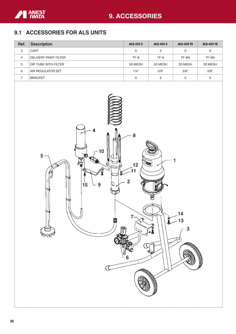
9. ACCESSORIES
Ref. Description ALS-333 C ALS-433 C ALS-433 TX ALS-423 TX
3 CART X X X X
4 DELIVERY PAINT FILTER TF-8 TF-8 TF-8N TF-8N
5 DIP TUBE WITH FILTER 50 MESH 50 MESH 30 MESH 30 MESH
6 AIR REGULATOR SET 1/4" 3/8" 3/8" 3/8"
7 BRACKET X X X X
9.1 ACCESSORIES FOR ALS UNITS
27
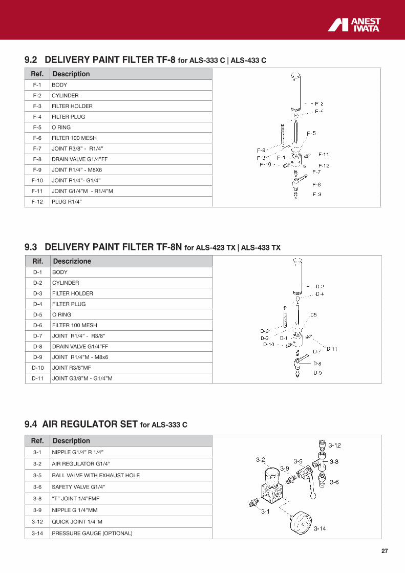
9.4 AIR REGULATOR SET for ALS-333 C
Ref. Description
3-1 NIPPLE G1/4” R 1/4”
3-2 AIR REGULATOR G1/4”
3-5 BALL VALVE WITH EXHAUST HOLE
3-6 SAFETY VALVE G1/4”
3-8 “T” JOINT 1/4”FMF
3-9 NIPPLE G 1/4”MM
3-12 QUICK JOINT 1/4”M
3-14 PRESSURE GAUGE (OPTIONAL)
9.2 DELIVERY PAINT FILTER TF-8 for ALS-333 C | ALS-433 C
Ref. DescriptionF-1 BODY
F-2 CYLINDER
F-3 FILTER HOLDER
F-4 FILTER PLUG
F-5 O RING
F-6 FILTER 100 MESH
F-7 JOINT R3/8” - R1/4”
F-8 DRAIN VALVE G1/4”FF
F-9 JOINT R1/4” - M8X6
F-10 JOINT R1/4”- G1/4”
F-11 JOINT G1/4”M - R1/4”M
F-12 PLUG R1/4”
9.3 DELIVERY PAINT FILTER TF-8N for ALS-423 TX | ALS-433 TX
Rif. DescrizioneD-1 BODY
D-2 CYLINDER
D-3 FILTER HOLDER
D-4 FILTER PLUG
D-5 O RING
D-6 FILTER 100 MESH
D-7 JOINT R1/4” - R3/8”
D-8 DRAIN VALVE G1/4”FF
D-9 JOINT R1/4”M - M8x6
D-10 JOINT R3/8”MF
D-11 JOINT G3/8”M - G1/4”M
28
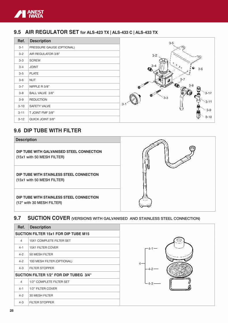
9.6 DIP TUBE WITH FILTER
Description
DIP TUBE WITH GALVANISED STEEL CONNECTION(15x1 with 50 MESH FILTER)
DIP TUBE WITH STAINLESS STEEL CONNECTION(15x1 with 50 MESH FILTER)
DIP TUBE WITH STAINLESS STEEL CONNECTION(12" with 30 MESH FILTER)
9.7 SUCTION COVER (VERSIONS WITH GALVANISED AND STAINLESS STEEL CONNECTION)
Ref. Description
SUCTION FILTER 15x1 FOR DIP TUBE M15
4 15X1 COMPLETE FILTER SET
4-1 15X1 FILTER COVER
4-2 50 MESH FILTER
4-2 100 MESH FILTER (OPTIONAL)
4-3 FILTER STOPPER
SUCTION FILTER 1/2" FOR DIP TUBEG 3/4"
4 1/2” COMPLETE FILTER SET
4-1 1/2” FILTER COVER
4-2 30 MESH FILTER
4-3 FILTER STOPPER
4-1
4-2
4-3
4
9.5 AIR REGULATOR SET for ALS-423 TX | ALS-433 C | ALS-433 TX
Ref. Description
3-1 PRESSURE GAUGE (OPTIONAL)
3-2 AIR REGULATOR 3/8”
3-3 SCREW
3-4 JOINT
3-5 PLATE
3-6 NUT
3-7 NIPPLE R 3/8”
3-8 BALL VALVE 3/8”
3-9 REDUCTION
3-10 SAFETY VALVE
3-11 T JOINT FMF 3/8”
3-12 QUICK JOINT 3/8”
29
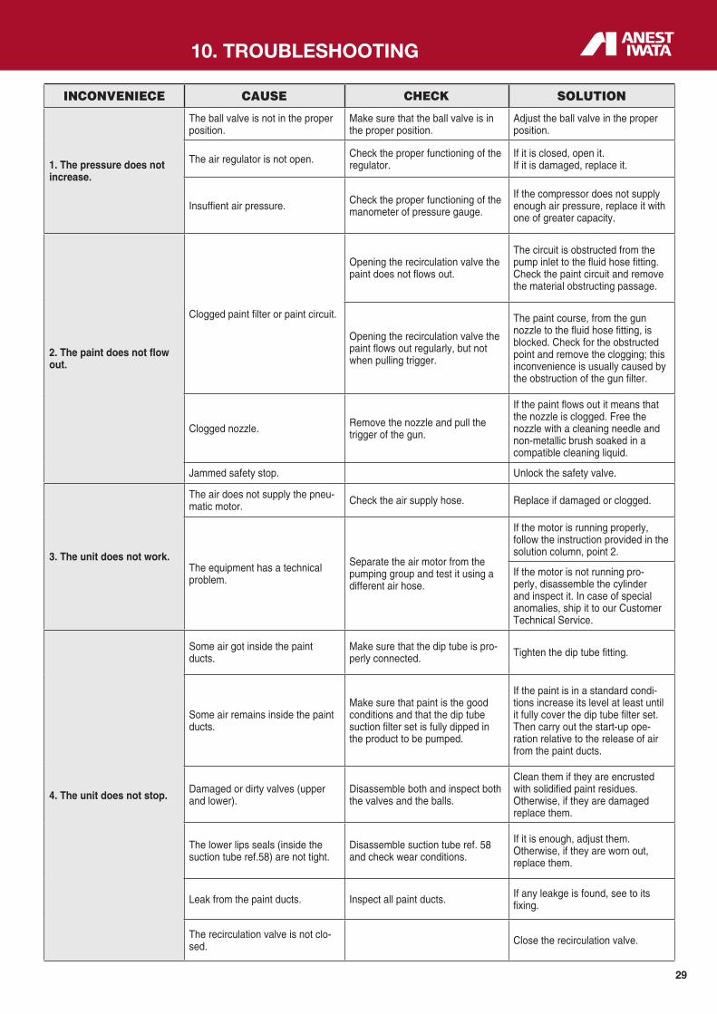
INCONVENIECE CAUSE CHECK SOLUTION
1. The pressure does not increase.
The ball valve is not in the proper position.
Make sure that the ball valve is in the proper position.
Adjust the ball valve in the proper position.
The air regulator is not open. Check the proper functioning of the regulator.
If it is closed, open it. If it is damaged, replace it.
Insuffient air pressure. Check the proper functioning of the manometer of pressure gauge.
If the compressor does not supply enough air pressure, replace it with one of greater capacity.
2. The paint does not flow out.
Clogged paint filter or paint circuit.
Opening the recirculation valve the paint does not flows out.
The circuit is obstructed from the pump inlet to the fluid hose fitting. Check the paint circuit and remove the material obstructing passage.
Opening the recirculation valve the paint flows out regularly, but not when pulling trigger.
The paint course, from the gun nozzle to the fluid hose fitting, is blocked. Check for the obstructed point and remove the clogging; this inconvenience is usually caused by the obstruction of the gun filter.
Clogged nozzle. Remove the nozzle and pull the trigger of the gun.
If the paint flows out it means that the nozzle is clogged. Free the nozzle with a cleaning needle and non-metallic brush soaked in a compatible cleaning liquid.
Jammed safety stop. Unlock the safety valve.
3. The unit does not work.
The air does not supply the pneu-matic motor. Check the air supply hose. Replace if damaged or clogged.
The equipment has a technical problem.
Separate the air motor from the pumping group and test it using a different air hose.
If the motor is running properly, follow the instruction provided in the solution column, point 2.
If the motor is not running pro-perly, disassemble the cylinder and inspect it. In case of special anomalies, ship it to our Customer Technical Service.
4. The unit does not stop.
Some air got inside the paint ducts.
Make sure that the dip tube is pro-perly connected. Tighten the dip tube fitting.
Some air remains inside the paint ducts.
Make sure that paint is the good conditions and that the dip tube suction filter set is fully dipped in the product to be pumped.
If the paint is in a standard condi-tions increase its level at least until it fully cover the dip tube filter set. Then carry out the start-up ope-ration relative to the release of air from the paint ducts.
Damaged or dirty valves (upper and lower).
Disassemble both and inspect both the valves and the balls.
Clean them if they are encrusted with solidified paint residues. Otherwise, if they are damaged replace them.
The lower lips seals (inside the suction tube ref.58) are not tight.
Disassemble suction tube ref. 58 and check wear conditions.
If it is enough, adjust them. Otherwise, if they are worn out, replace them.
Leak from the paint ducts. Inspect all paint ducts. If any leakge is found, see to its fixing.
The recirculation valve is not clo-sed. Close the recirculation valve.
10. TROUBLESHOOTING

30
IMPORTANT: IN CASE OF REPLACEMENT ALWAYS USE GENUINE PARTS ANEST IWATA. Non original parts may compromise the Unit's operation.
INCONVENIECE CAUSE CHECK SOLUTION
5. The spray gun pattern size, keeps changing.
Worn out lips seals. Check the lips seals.If it is enough, adjust them. Otherwise, if they are worn out, replace them.
Damaged or dirty valves or balls. The unit does not stop. Disassemble and clean them. Replace them if they are damaged.
Worn out inner or outer valves (23 and 17) placed inside the air motor.
There is a leakage noise. Replace the valves.
Worn out inner gun nozzle. Replace it.
Dirty paint filters. Clean or replace them.
6. The manometer indicates the presence of pressure even though the air regula-tor is closed.
Damaged air regulator. Replace it.

31
11.1 EQUIPMENT STORAGE
If the Airless unit is to be stored for a certain period, the following operations are recommended: Disconnect the equipment from the energy sources. Remove all residues and deposits from the pump. Cover the equipment with a waterproof tarpaulin.
11.2 DISMANTLING
If for any reason the pump is to be dismantled, some important rules have to be followed to safe guard the environment.
All sheaths, flexible ducts and plastic or non metal components will have to be disposed of separately.
11. DISMANTLING
Code No.: W5IM0024 - EN - July_2016
ANEST IWATA CorporationYokohama - JAPAN
Headquarter:
EU
RO
PE
AN
SA
LE
S O
FFIC
ES:
ANEST IWATA France S.A.Saint Quentin Fallavier, Lyon - [email protected]
ANEST IWATA U.K. Ltd.St.Neots Cambridgeshire - [email protected]
ANEST IWATA Scandinavia AB.Partille, Göteborg - [email protected]
ANEST IWATA Iberica S.L.Badalona, Barcelona - [email protected]
ANEST IWATA Deutschland GmbHLeipzig - [email protected]
ANEST IWATA Polska Sp. Z o.o.Poznañ - [email protected]
ANEST IWATA Italia S.r.l.Torino - [email protected] www.anest-iwata.it
SA
LE
S O
FFIC
ES:
ANEST IWATA USA Inc.West Chester - Ohio - [email protected]
ANEST IWATA do Brasil Comercial Ltd.Sao Paulo - [email protected]
ANEST IWATA Russia LLCMoscow - [email protected]
ANEST IWATA Shanghai CorporationShanghai - [email protected]
ANEST IWATA Taiwan CorporationHu-Kuo - TAIWAN [email protected]
ANEST IWATA Vietnam CO. Ltd.Ho Chi Minh City- [email protected]
ANEST IWATA Motherson Coating Equipment Ltd.Noida - [email protected]/anest-iwata-motherson.html
ANEST IWATA Southeast Asia CO. Ltd.Bangkok - [email protected]
ANEST IWATA Middle East FZEDubai - UNITED ARAB [email protected]
ANEST IWATA Australia Pty Ltd.Sidney - [email protected]
ANEST IWATA South Africa Pty Ltd.Johannesburg - REPUBLIC OF SOUTH AFRICAwww.anest-iwata.co.za
PT. ANEST IWATA IndonesiaJakarta - INDONESIAwww.anest-iwatasoutheastasia.com
ANEST IWATA Coating Solutions CorporationYokohama - JAPANwww.anest-iwataeu.co.jp