Embed Size (px)
Citation preview

USCMS/HCAL/TriDas. October, 2003 HCAL TriDAS 1
Tridas Status
Drew BadenUniversity of Maryland
October 2003

USCMS/HCAL/TriDas. October, 2003 HCAL TriDAS 2
HTR Status
Dual-LC O-to-E
VME
Deserializers
Xilinx XC2V3000
-4
Sti
ffen
er
s
SLBs (6)
TTC mezzanine
• Rev 3 – 30 boards made in March 2003
– Board production changes:• New assembler, in-house X-ray,
DFM review, QC• Gold plated (Rev 1 was white-tin)
for better QC– Changes to HTR:
• Change from FBGA (1.00mm) to BGA (1.27mm)
• Added stiffeners• Moved all SLB/TPG output to
front-panel daughterboards• Modified Rx refclk scheme (the
usual TTC/refclk clocking concerns)
– Full 48 channel capability • Rev 1 in 2002 was “half HTR”

USCMS/HCAL/TriDas. October, 2003 HCAL TriDAS 3
Changes to HTR for Rev4
• Moved 2 LC’s down to giver more clearance for fibers– Upper rear of card
• Spread out routing of differential pairs for 6 SLB and 2 FPGA system clocks
• Removed hot swapping circuits– Worry about noise, decided not to
require HTR to be hot swappable• Front-panel changes
– Rotary switch, LEDs, eliminate REFCLK mux via jumper, etc
• Miscellaneous changes– Fixed what was found to be wrong with
Rev3 board, add test points, terminate all unterminated I/O lines to SLB, VME byte swapping, other minor stuff

USCMS/HCAL/TriDas. October, 2003 HCAL TriDAS 4
TODO - TPG
• HTR production can begin after:– SLB/HTR/Wisconsin check
• Check that we can maintain link• Setup ready…so far so good• Measure BER, etc.
– SLB/HTR connectivity check• Logic analyzer card on SLB site already
shows connectivity• Waiting for firmware for SLB to verify for
sure– Should be this week or next
• TPG Data validation– Will build a 6U VME board with sites for the
Wisconsin Vitesse receiver boards– Will fifo data and read out over VME– Use this to check data validity, try different
TPG tests, etc.– Plan to start on this board by Nov 1– Ready in a few months. Will use this for the
early slice tests to test TPG output.
FPGA
Clock Input

USCMS/HCAL/TriDas. October, 2003 HCAL TriDAS 5
TTC receiver - TTCumd
• General purpose TTC receiver board (TTCumd)
– TTCrx ASIC and associated PMC connectors
• Will be used to receive TTC signal by HTR, DCC, and clock fanout boards• No signal receivers
– Copper/fiber receivers must be on the motherboard
– Signal driven through TTC connectors• Tested successfully
– Maryland, Princeton, BU, FNAL– Testbeam H2
• Production:– Need 1 per HTR (~260) + DCC (20) +
Fanout (10)– Need ~500 TTCrx for HCAL– Will layout test board for rapid testing
en mass

USCMS/HCAL/TriDas. October, 2003 HCAL TriDAS 6
Clocks and Synchronization
• Clocking considerations can be divided into 2 parts:– Deserializers REFCLK: stability critical (80MHz frame rate)
• Stability: must have a very low jitter – 40ps pkpk spec• Frequency: TI TLK2501 spec is 100ppm (8kHz) to lock
– Measured ~350ppm (30kHz) needed to establish link» LHC variation expected to be few kHz
– Once link is established, just needs to be stable (it’s a REFCLK!!!)
• Phase: relationship to LHC clock totally irrelevant
– Phase critical clock for pipeline synchronization• Must be in phase with LHC clock• Jitter spec is less stringent
– For FPGA sequential logic
– For SLB transmission 80ps pkpk
USCMS/HCAL/TriDas. October, 2003 HCAL TriDAS 7
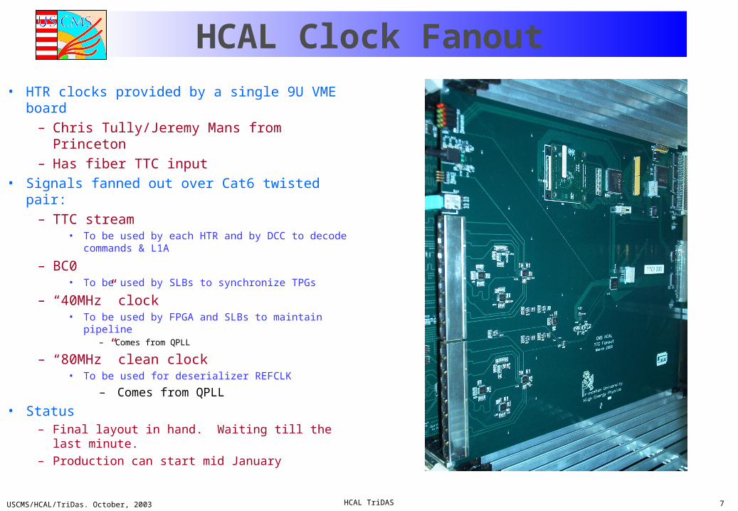
HCAL Clock Fanout
• HTR clocks provided by a single 9U VME board– Chris Tully/Jeremy Mans from Princeton– Has fiber TTC input
• Signals fanned out over Cat6 twisted pair:– TTC stream
• To be used by each HTR and by DCC to decode commands & L1A
– BC0• To be used by SLBs to synchronize TPGs
– “40MHz” clock• To be used by FPGA and SLBs to maintain pipeline
– Comes from QPLL
– “80MHz” clean clock• To be used for deserializer REFCLK
– Comes from QPLL
• Status– Final layout in hand. Waiting till the last minute.
– Production can start mid January

USCMS/HCAL/TriDas. October, 2003 HCAL TriDAS 8
Clock Distribution
HTR
TTC fiber
TTC
CLK80
BC0
CLK40
distributionto 6 SLBs
and to 2 Xilinx
Brdcst<7:0>,BrcstStr, L1A
O/E
BC0
TTCTTC
TTC
FPGA
..
..
TestPoints forRxCLKand RxBC0
..
..
..
..
80.18 MHz
..
..
..
..
TTCrx
to Ref_CLK of SERDES(TLK2501)
CLK40
CLK80
Princeton FanoutBoard
TTCrx
QPLL
HTRHTR
Cat6Eor Cat7Cable

USCMS/HCAL/TriDas. October, 2003 HCAL TriDAS 9
Testbeam 2003
• Lack of a QPLL – we had to improvise:– Front-end used commercial Cypress PLL
• Beats GOL 100ps pkpk jitter spec in the lab• Terry Shaw measured sufficiently small jitter on backplane
– Fanout card • No clean 80MHz REFCLK, so provided 2 alternatives:
– 2xLHC clock from crystal oscillator– High quality clock from HP signal and pulse generators– Jumper selectable on mezzanine cards
• No clean 40MHz system clock– Just used 40MHz output from TTCrx chip anyway– Worked well enough
» The system clock doesn’t need a low jitter spec, and Xilinx has a DLL to clean it up
– Much struggling with the fiber links, synchronization issues, etc.

USCMS/HCAL/TriDas. October, 2003 HCAL TriDAS 10
Testbeam 2003
• What we struggled with and learned about– Fiber links
• FE Tx clock critical. No QPLL so we used backup plan.• Great deal of experience gained here.
– TTC• Had a few minor issues, discover how to best synch L1A with pipeline
– DAQ• Production DCC logic board
– Able to operate SLINK64 smoothly– Logic in place for inline error checking, data integrity, etc
• XDAQ implementation experience
– Calorimeter• Took useful calorimeter data.
– HB, HE, HO, HF

USCMS/HCAL/TriDas. October, 2003 HCAL TriDAS 11
Testbeam Experience• Fiber synchronization
– FE• With crystal oscillator on FE, few troubles
– Still some mysteries…much better results in US tests
• TTC 40MHz clock cleaned up by Cypress “roboclock” chip (Cy7B993)– Many synch errors, varied from fiber-to-fiber, hard to maintain link on all fibers
over ~few hours time period– During synchronized beam running, sent reset between spills to ensure link.
This seemed to work ok. Exploring using rescynch in abort gap…
– Fanout card• Fanout from onboard ~80MHz crystal oscillator for REFCLK• Fanout TTC 40MHz clock for system clock
– HTR• 40MHz system clock scheme worked
– Some firmware changes necessary to synchronize with L1A
• TLK2501 link circuitry always enabled.

USCMS/HCAL/TriDas. October, 2003 HCAL TriDAS 12
Fiber Links (cont)• Tests at Maryland using TI eval board and Stratos transmitter
– Link exceedingly stable (see slides below)• Current plan
– Study FE → HTR link at FNAL• FNAL test stand is setup, link tests underway, more to come this fall
– Investigate noise characteristics of H2 environment• H2 is clearly different than FNAL, Maryland (and BU) experience
– Review of HTR and Fanout card• Will learn what we need to do from the above
• Best guess– All tests in US indicate solid link, but experience in H2 disagree– Probably a linear combination of:
• TTC clock jitter (most likely)• Some kind of new noise component (less likely – FE works with crystal oscillators)
• Bottom line:– We have a system that works in our labs (BER<10-14) but…
• H2 environment? Need more studies during the next 6-12 months• Lack of working QPLL. Looking forward to getting correct QPLL/crytals

USCMS/HCAL/TriDas. October, 2003 HCAL TriDAS 13
Optical Attenuation and BER• “Typical setup”
– VECSEL transmitter, coupled to fiber via LC connector• Not locked, but fixed in place
– Fiber to LC to 8-way MTP male on HTR front panel– Single fiber to LC connector for connection to STRATOS receiver
• Output power:– VECSEL advertised to put out 500W (-3dBm)
• Terry Shaw measured 570W for a particular VECSEL– UMD uses STRATOS LC transmitter
• Advertised output 100-400W (-4 to -10dBM)• Measured to be 90W for a particular STRATOS• About 6dB below what we will use in CMS• Working on FE emulator now using GOL+VECSEL…
• Attenuations measured:– At each LC connector, 10 – 50% (0.5 to 1.5 dB)– At MTP connector, same thing (.75dB advertised)– Fibers are about ¼ dB per 100m
FE
VECSEL
LC
MTP (8-way)
LCLCStratos
HTR
USCMS/HCAL/TriDas. October, 2003 HCAL TriDAS 14
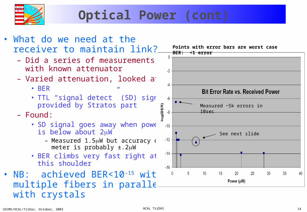
Optical Power (cont)
• What do we need at the receiver to maintain link?– Did a series of measurements with
known attenuator– Varied attenuation, looked at:
• BER• TTL “signal detect” (SD) signal provided
by Stratos part
– Found:• SD signal goes away when power is
below about 2W– Measured 1.5W but accuracy of meter
is probably ±.2W
• BER climbs very fast right at this shoulder
• NB: achieved BER<10-15 with multiple fibers in parallel with crystals
Measured ~5k errors in 10sec
Points with error bars are worst case BER: <1 error
See next slide

USCMS/HCAL/TriDas. October, 2003 HCAL TriDAS 15
Link Loss Observation
• Ran a test at 7.4W (-21dBm), found 44 errors in 18 hours• Simultaneously triggered scope on VCC to transmitter and
crate• Found that the scope had triggered on transmitter voltage
but not crate– Voltage spike - 1-2V oscillation with ~50ns rise time– Crate was isolated through UPS
• These errors were due to a spike on the A/C line from equipment being power cycled, noise in building, etc.
• Moral: noise in the power/grounds will be our nightmare
USCMS/HCAL/TriDas. October, 2003 HCAL TriDAS 16
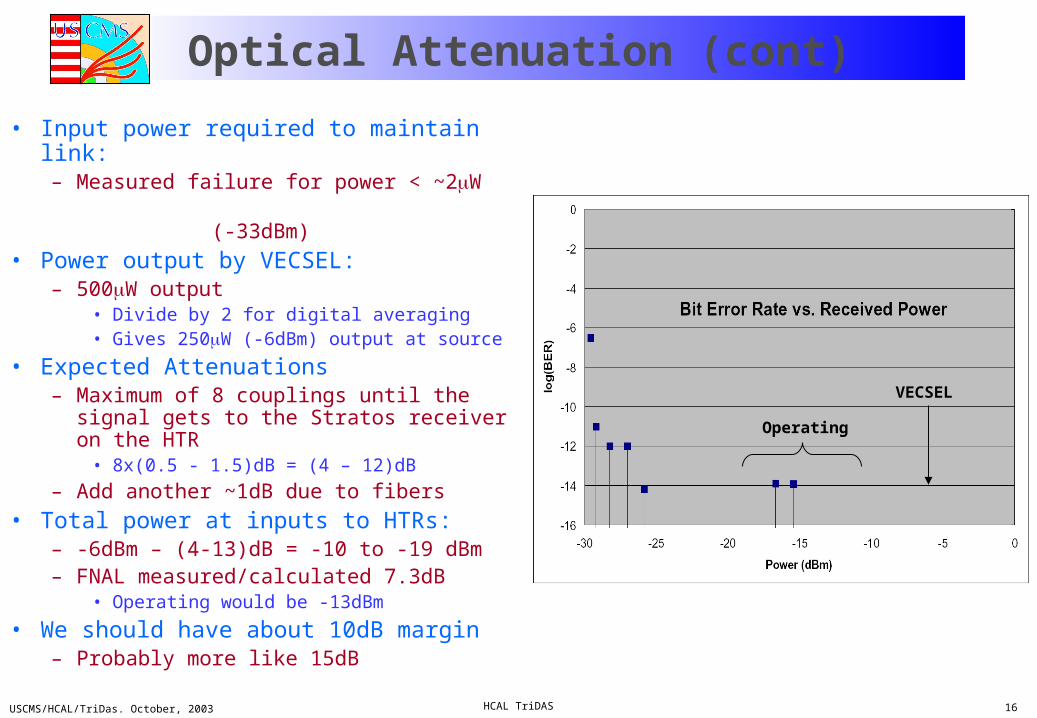
Optical Attenuation (cont)
• Input power required to maintain link:– Measured failure for power < ~2W (-33dBm)
• Power output by VECSEL:– 500W output
• Divide by 2 for digital averaging• Gives 250W (-6dBm) output at source
• Expected Attenuations– Maximum of 8 couplings until the signal
gets to the Stratos receiver on the HTR• 8x(0.5 - 1.5)dB = (4 – 12)dB
– Add another ~1dB due to fibers
• Total power at inputs to HTRs:– -6dBm – (4-13)dB = -10 to -19 dBm– FNAL measured/calculated 7.3dB
• Operating would be -13dBm
• We should have about 10dB margin– Probably more like 15dB
VECSEL
Operating

USCMS/HCAL/TriDas. October, 2003 HCAL TriDAS 17
Longitudinal Separation Attenuation
• MTP connector ends are spring loaded into adapter
• Measured attenuation as a function of the separation– Separation should be ~0 if keys
and adapters are working well– This should not be an issue for us
(famous last words….)

USCMS/HCAL/TriDas. October, 2003 HCAL TriDAS 18
Project Timeline
2003 2004
Firmware TB 03 firmware should be adequateBoards Can use current crop of Rev3
To do: Commission QPLL, global clocking. Level 1 Trigger: SLB, TPG, latency…
“Vertical Slice” (~March)
2005
HB, HE, and ME plus Level 1/TPGFiber synchronization Check in alcove…compare environmentsFirmware TPG firmware has to be ready. Fall 03 task.Boards Must have Rev4. How many TBD.
FE Commissioning (~Feb)
“Magnet” Tests (no HCAL)
CMS Magnet Integration System TestBoards Will have Rev4.
H2 Testbeam
Fiber synchronization Check in H2…compare environmentsBoards Will have Rev4. How many TBD.

USCMS/HCAL/TriDas. October, 2003 HCAL TriDAS 19
HTR Firmware

USCMS/HCAL/TriDas. October, 2003 HCAL TriDAS 20
TPG Path
• Still under development– The following is already coded/simulated but not tested in HTR
• TPG path tasks (not necessarily in order)– Linearize QIE data to 10 bits
• With .5GeV resolution gives 512 GeV max
– Apply BCID filter• Probably will sum over 2 buckets and assign based on high/low patter
around the bucket that has the max energy
– Sum or divide depending on HB, HE, or HF– Extract a muon window for the “feature bit”– Apply logic to eliminate false muons from shower leakage, etc.– Compress and send to SLB

USCMS/HCAL/TriDas. October, 2003 HCAL TriDAS 21
TPG Path Schematic

USCMS/HCAL/TriDas. October, 2003 HCAL TriDAS 22
TODO (cont)
• Firmware– Focus on L1 latency optimization
• Measure full latency, scheme for random TLK latency, how to meet L1 latency budget, etc.
• This will be the main activity from now until we go into production.
– Bells and whistles for error reporting/recover• Meeting next week in Princeton to finalize what we learned in 2003• More to be learned in 2004
• HTR boards– Make Rev4 this fall, go into production early 04
• ASAP given schedule• Depends on results from above

USCMS/HCAL/TriDas. October, 2003 HCAL TriDAS 23
Latency
• Definition: from BX to input to RCT
HCAL O-E QIE CCA HTR SLB RCTBX TOF To RBX Data To RCT
RBXHPD or PMT (HF)
46 clocks = 1,147.7ns
GOL

USCMS/HCAL/TriDas. October, 2003 HCAL TriDAS 24
TOF+Y11/fiber to RBX
10.855
4.332
HCAL O-E QIE CCA HTR SLB RCTBX TOF To RBX Data To RCT
RBXHPD or PMT (HF)
46 clocks = 1,147.7ns
GOL
TOF Tx to RBX (7ns/m) TOTAL
HB =1 layer 1 (1.8m) 6.1ns (4.9m) 34.1ns 40.2ns
HB =15 layer 9 (4.6m) 15.4ns (0.6m) 4.2ns 19.6ns
HE =34 layer 1 (4.0m) 13.3ns (3.3m) 22.9ns 36.2ns
HB =17 layer 14
(5.7m) 19.1ns (0.3m) 2.0ns 21.1ns
HF (10.9m) 36.3ns (2m quartz) 14ns 50.3ns

USCMS/HCAL/TriDas. October, 2003 HCAL TriDAS 25
Inside RBX
• CCA delays will be set using LED system
TOF+Tx O-E Total to CCA Clocks QIE CCA+GOL Total
HB 40.2 (HPD) 0ns 40.2ns 1.6 (1) 4 3+2 10
HE 36.2 (HPD) 0ns 36.2ns 1.5 (1) 4 3+2 10
HF 50.3 (1.5kv PMT + 6m coax)
14ns + 30ns = 44ns
94.3ns 3.8 (3) 4 3+2 12
Assumes CCA can absorb <1 clock tick phase (?)
HCAL O-E QIE CCA HTR SLB RCTBX TOF To RBX Data To RCT
RBXHPD or PMT (HF)
46 clocks = 1,147.7ns
GOL

USCMS/HCAL/TriDas. October, 2003 HCAL TriDAS 26
Digital Data Fiber
• Measured = 2/3 (51m adds 250ns delay)– Gives 4.99 m/clock tick (@40.08MHz LHC RF frequency)
• Default fiber length 90m gives 18.036 clocks– Use 18, make fibers <90m– HE is longest due to routing around ME outer radius
• Change HE fiber routing to go via EE inner radius– We believe we can shave off 15-20m
• 3 clocks – 15 total
• maybe more?
Thru RBX Data Fiber Total
HB 10 15 25
HE 10 15 25
HF 12 15 27
HCAL O-E QIE CCA HTR SLB RCTBX TOF To RBX Data To RCT
RBXHPD or PMT (HF)
46 clocks = 1,147.7ns
GOL

USCMS/HCAL/TriDas. October, 2003 HCAL TriDAS 27
Random Latencies in HTR
• Latency due to – TI deserializer (TLK2501)
• Advertised random latency with respect to reset 76 to 106 bit times
– Remember, TLK2501 has 20-bit frames
– Latency will be 47.5 to 66.9 ns random
• We measured the random latency at UMD
– Latency difference is randomly distributed between 0 and 6ns.
– Factor of ~1/3 of TI spec. Will investigate if this is “typical”
– Asynchronous fifo• Relative phase between recovered
clock and refclk will introduce a random latency of 0 to 1 clock tick
TLK2501
TLK2501
Common 80MHz system clock = 40MHz clock/2 from TTC
USCMS/HCAL/TriDas. October, 2003 HCAL TriDAS 28
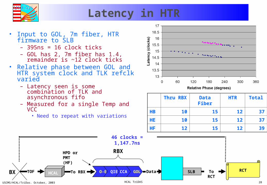
Latency in HTR
• Input to GOL, 7m fiber, HTR firmware to SLB– 395ns = 16 clock ticks– GOL has 2, 7m fiber has 1.4,
remainder is ~12 clock ticks• Relative phase between GOL and
HTR system clock and TLK refclk varied– Latency seen is some combination of
TLK and asynchronous fifo– Measured for a single Temp and VCC
• Need to repeat with variations
Thru RBX Data Fiber HTR Total
HB 10 15 12 37
HE 10 15 12 37
HF 12 15 12 39
HCAL O-E QIE CCA HTR SLB RCTBX TOF To RBX Data To RCT
RBXHPD or PMT (HF)
46 clocks = 1,147.7ns
GOL
USCMS/HCAL/TriDas. October, 2003 HCAL TriDAS 29
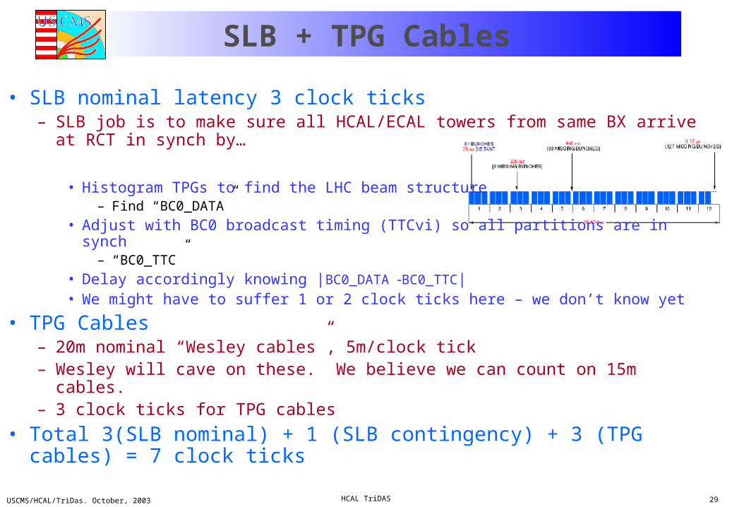
SLB + TPG Cables
• SLB nominal latency 3 clock ticks– SLB job is to make sure all HCAL/ECAL towers from same BX arrive at RCT
in synch by…
• Histogram TPGs to find the LHC beam structure– Find “BC0_DATA”
• Adjust with BC0 broadcast timing (TTCvi) so all partitions are in synch– “BC0_TTC”
• Delay accordingly knowing |BC0_DATA BC0_TTC|• We might have to suffer 1 or 2 clock ticks here – we don’t know yet
• TPG Cables– 20m nominal “Wesley cables”, 5m/clock tick– Wesley will cave on these. We believe we can count on 15m cables.– 3 clock ticks for TPG cables
• Total 3(SLB nominal) + 1 (SLB contingency) + 3 (TPG cables) = 7 clock ticks

USCMS/HCAL/TriDas. October, 2003 HCAL TriDAS 30
Grand Total
• Caveats:– Numbers for TOF+prog delay are correct (please
check!)– 75m max for all fiber cables (saves 3 clocks)– CCA can take up some of the slack for
TOF+propogation delays (<1clock)– CCA can be run with a latency of 3 and still do its job (5
max for the chip)– 3m TPG cables– No summing in HTR firmware– Total delay through SLB < 4 (1 for contingency, need
experience here)• Possible further additions to total latency
– TOF+propogation (+HF delays thru PMT and coax)– Digital fiber cabling could go back to 90?– Need to implement summing in HTR firmware – we
need a MC study to tell us we need this.• Default should be no summing unless MC study tells us
otherwise– Difficulties with SLB
• Possible further scrubbing– Digital fiber cabling (Ianos and Laza are on top of this…)– “Tricks” in HTR firmware– Perhaps save another clock in CCA for HF (discussing
with Terry)– Any other clever ideas?
Thru RBX
Data Fiber
HTR SLB/TPG
Total
HB 10 15 12 7 44
HE 10 15 12 7 44
HF 12 15 12 7 46