Embed Size (px)
Citation preview

MAN-000012 REVISION G
USB and 1394b EXTENDER USB Models 1.1 and 2.0
Firewire Model 800
Product Manual
Thinklogical™ Inc. 100 Washington Street
Milford, Connecticut 06460 U.S.A.
Telephone (203) 647-8700 Fax (203) 783-9949
www.thinklogical.com

MAN-000012 i REVISION G
Copyright Notice
Copyright © 2008 All rights reserved. Printed in the U.S.A.
Thinklogical™, a subsidiary of Logical Solutions, Incorporated 100 Washington Street
Milford, Connecticut 06460 U.S.A. Telephone (203) 647-8700
All trademarks and service marks are property of their respective owners.
Document ID: MAN-000012 Subject: USB and 1394b EXTENDER Revision: Rev F, SEPTEMBER 2008

MAN-000012 ii REVISION G
Table of Contents Products: USB Extenders ........................................................................................................................ 1 1. Introduction ...................................................................................................................................... 2
1.1. Contents ................................................................................................................................... 2 1.1.1. USB Extender ..................................................................................................................... 2
1.2. Product Overview ..................................................................................................................... 2 1.2.1. USB Extender ..................................................................................................................... 2 1.2.2. USB Camera ...................................................................................................................... 2
1.3. Ordering Information ................................................................................................................. 3 1.4. Laser Information ...................................................................................................................... 3
2. System Features .............................................................................................................................. 4 2.1. General System Features ......................................................................................................... 4 2.2. Technical Specifications ........................................................................................................... 4 2.3. Product Overview - USB Extender ............................................................................................ 5
2.3.1. USB 1.1 Transmitter ........................................................................................................... 6 2.3.2. USB 1.1 Receiver ............................................................................................................... 7 2.3.3. USB 2.0 Transmitter ........................................................................................................... 8 2.3.4. USB 2.0 Receiver ............................................................................................................... 9 2.3.5. Cables .............................................................................................................................. 10 2.3.6. Power Supply –PWR-000022-R (Quantity 2) .................................................................... 11 2.3.7. Power Supply – PWR-000047-R (Quantity 2) ................................................................... 11
3. Installation ...................................................................................................................................... 13 3.1. LED Status ............................................................................................................................. 13
3.1.1. Transmitter ....................................................................................................................... 13 3.1.2. Receiver ........................................................................................................................... 14
Product: Firewire 800 Extender .............................................................................................................. 15 1. Introduction .................................................................................................................................... 16
1.1. Contents ................................................................................................................................. 16 1.1.1. Firewire (1394b) ................................................................................................................ 16 1.1.2. Firewire (1394b) Extender ................................................................................................ 16
1.2. Laser Information .................................................................................................................... 16 2. System Features ............................................................................................................................ 17
2.1. General System Features ....................................................................................................... 17 2.2. Technical Specifications ......................................................................................................... 17 2.3. Product Overview – Firewire 800 Extender ............................................................................. 18
2.3.1. Firewire 800 Transmitter ................................................................................................... 19 2.3.2. Firewire 800 Receiver ....................................................................................................... 20 2.3.3. Cables .............................................................................................................................. 21 2.3.4. Power Supply – PWR-000033-R (Quantity 2) ................................................................... 22
3. Installation ...................................................................................................................................... 23 3.1. LED Status ............................................................................................................................. 24
3.1.1. Transmitter ....................................................................................................................... 24 3.1.2. Receiver ........................................................................................................................... 24
Product Identification ............................................................................................................................. 25 1. Markings ........................................................................................................................................ 25
1.1. Product Serial Number ........................................................................................................... 25

MAN-000012 iii REVISION G
1.2. Symbols Found on Product .................................................................................................... 25 Safety Standards ................................................................................................................................... 26 1. Laser Module ................................................................................................................................. 26 2. External Fiber Connector ............................................................................................................... 26 3. USB 1.1 and 2.0 Power Supply ...................................................................................................... 26 4. Firewire 800 Power Supply ............................................................................................................. 26 How to Contact Us ................................................................................................................................. 27 1. Customer Support .......................................................................................................................... 27
1.1. Website .................................................................................................................................. 27 1.2. Email ...................................................................................................................................... 27 1.3. Telephone .............................................................................................................................. 28 1.4. Fax ......................................................................................................................................... 28
2. Product Support ............................................................................................................................. 29 2.1. Warranty ................................................................................................................................. 29 2.2. Our Address ........................................................................................................................... 30
Appendix A - Dimensions ....................................................................................................................... 31 1. USB 1.1 and 2.0 Transmitter .......................................................................................................... 31 2. USB 1.1 and 2.0 Receiver .............................................................................................................. 32 3. Firewire 800 Transmitter ................................................................................................................ 33 4. Firewire 800 Receiver .................................................................................................................... 34


MAN-000012 1 REVISION G
Products: USB Extenders
USB 1.1 Extender
and
USB 2.0 Extender

MAN-000012 2 REVISION G
1. Introduction 1.1. Contents
1.1.1. USB Extender When you receive your Thinklogical™ USB Extender (1.1 or 2.0 Model), you should find the following items:
USB Extender – Transmitter USB Extender – Receiver AC Power Supply (PWR-000022-R) – Quantity 2 USB Cable, 6 Feet (CBL000015-006FR) USB and 1394b Extender Product Manual
NOTE: The USB 2.0 Extender is recommended for video transfer applications; the USB 1.1 Extender is recommended for all other applications.
NOTE: For USB camera applications which limit power, we recommend the Thinklogical™ USB 2.0 EP Series. The EP Series is only available in the USB 2.0 Model.
1.2. Product Overview
1.2.1. USB Extender The USB Extender (1.1 and 2.0 Models) is a fiber optic extender designed to extend USB 1.1 or 2.0 interface signals up to 1000 meters (3280 feet) over a standard duplex multimode fiber. With the USB Extender, all high speed USB 1.1 or 2.0 peripherals can be conveniently located while operating at optimal speed. The USB 2.0 Extender effectively supports not only USB 2.0 peripherals but USB 1.1 low speed and full speed devices as well. The USB Extender transmitter connects to the host computer with a standard USB cable and the receiver provides four ports for connection of peripheral devices. External power is required for both the transmitter and receiver units and two universal power supplies are included. Plug-and-play with no adjustments makes setting up the USB Extender fast and easy. As an added bonus, LEDs provide link performance at a glance. The USB Extender successfully and effectively delivers USB peripherals when and where you need them.
1.2.2. USB Camera For USB camera applications which limit power, we recommend the Thinklogical™ USB 2.0 EP Series. The EP (Enhanced Power) Series is only available in the USB 2.0 Model. This optional feature can handle additional power that USB cameras require.

MAN-000012 3 REVISION G
1.3. Ordering Information All models listed are available from Thinklogical™: USB-000001-SCTX USB 1.1 EXTENDER TRANSMITTER, SC USB-000001-SCRX USB 1.1 EXTENDER RECEIVER, SC USB-000001-STTX USB 1.1 EXTENDER TRANSMITTER, ST USB-000001-STRX USB 1.1 EXTENDER RECEIVER, ST USB-000002-SCTX USB 2.0 EXTENDER TRANSMITTER, SC USB-000002-SCRX USB 2.0 EXTENDER RECEIVER, SC USB-000002-STTX USB 2.0 EXTENDER TRANSMITTER, ST USB-000002-STRX USB 2.0 EXTENDER RECEIVER, ST
USB-EP0002-SCTX USB 2.0 EXTENDER, ENHANCED POWER, TRANSMITTER, SC USB-EP0002-SCRX USB 2.0 EXTENDER, ENHANCED POWER, RECEIVER, SC USB-EP0002-STTX USB 2.0 EXTENDER, ENHANCED POWER, TRANSMITTER, ST USB-EP0002-STRX USB 2.0 EXTENDER, ENHANCED POWER, RECEIVER, ST
1.4. Laser Information
LASER RADIATIONDO NOT VIEW DIRECTLY WITH OPTICAL
INSTRUMENTS
CAUTION: In order to avoid possible exposure to laser energy, it is good practice to attach the fiber optic cables prior to applying power to the USB EXTENDER. If the fiber optic cable should become disconnected, DO NOT attempt to look into the cable or the panel mounted connector.

MAN-000012 4 REVISION G
2. System Features 2.1. General System Features
Extends Hi-Speed USB 1.1 or 2.0 connection up to 1000 meters (3280 feet) Four port Class A device Installation is Plug-and-Play, no adjustments are necessary Supports USB 1.1 low-speed /full-speed and USB 2.0 hi-speed devices Uses standard duplex multi-mode fiber optic cable LEDs provide link performance status Available with your choice of ST or SC fiber connectors
2.2. Technical Specifications Storage Temperature -20 to 85 °C (-4 to 185 °F)
Supply Voltage 5.0 VDC ±5%. Adapter has Universal AC Power Input
Polarity: Positive Tip Part Number: PWR-000022-R
Power Consumption 5 Watts
Laser Output Specifications Meets Laser Class 1M Specifications
Panel Connectors Transmitter: (1) USB Type B connector (1) Dual Fiber connector (SC or ST) (1) 2.5mm power connector
Receiver: (4) USB Type A connectors (1) Dual Fiber connector (SC or ST)
(1) 2.5mm power connector
Optical Cable Duplex Fiber, multi-mode, 50 micron or 62.5 micron. (Fiber Cable is either customer-supplied or can be ordered from Thinklogical.)
Operating Temperature and Humidity
0 to 50 °C (32 to 122 °F); 10 to 95% RH, non-condensing
Enclosure Dimensions 6.61in x 4.00in x 1.09in (167.89mm x 101.60mm x 27.61mm) Tolerance: ± 0.039in (1mm)
Weight 1lb (0.45kg) each
Shipping Weight Transmitter and Receiver: 4lbs (1.81kg)
Copper Cables (1) USB Type A to USB Type B Cable, 6 Feet Part Number: CBL000015-006FR
MAN-000012 5 REVISION G
2.3. Product Overview - USB Extender
CCD Camera

MAN-000012 6 REVISION G
2.3.1. USB 1.1 Transmitter
5VDC
POWER LINKT R
HOST

MAN-000012 7 REVISION G
2.3.2. USB 1.1 Receiver
5VDC
POWER LINKT R
1 2 3 4

MAN-000012 8 REVISION G
2.3.3. USB 2.0 Transmitter
5VDC
POWER LINKT R
HOST

MAN-000012 9 REVISION G
2.3.4. USB 2.0 Receiver
5VDC
POWER LINKT R
1 2 3 4

MAN-000012 10 REVISION G
2.3.5. Cables
2.3.5.1. Fiber Optic Cables Fiber Optic cables for the USB Extender system are not included, but are available for purchase. Please contact Thinklogical™ for a quotation on your required cable length.
When connecting the fiber optic cables, you must be sure to:
Connect the fiber connector labeled „T‟ on the Transmitter to the fiber connector
labeled „R‟ on the Receiver. Connect the fiber connector labeled „R‟ on the Transmitter to the fiber connector
labeled „T‟ on the Receiver.
*Note: Place Transmitter and Receiver units with the fiber panels facing each other. When you connect the fibers, THE FIBER CABLE SHOULD NOT BE CROSSED.
2.3.5.2. USB Type A – Receiver Connect up to four devices(s) into any of the device port(s) labeled 1,2,3,4 on the
Receiver unit. The cable that was provided with your USB device should be able to connect to the USB Type A ports on the Receiver.
2 Fibers
Up to 1000 meters
(USB 2.0)

MAN-000012 11 REVISION G
2.3.5.3. USB Type B – Transmitter
Connect your PC to the location labeled Host on the Transmitter unit using the USB Type A to USB Type B Cable (CBL000015-006FR) that was provided with your USB Extender system.
2.3.6. Power Supply –PWR-000022-R (Quantity 2)
Universal Input: 100 – 240 VAC 50/60Hz Nominal Continuous Short Circuit Protection Over Voltage Protection Conductive EMI Meets CISPR/FCC Class B high efficiency, 75% Typical AC Plug Can Be Changed
AC Power Supply (PN: PWR-000022-R) shown with optional AC plugs
2.3.7. Power Supply – PWR-000047-R (Quantity 2)
NOTE: PWR-000047-R is supplied for the EP (enhanced power).

MAN-000012 12 REVISION G
Separate wall-pack AC/DC adapters (part number PWR-000022-R) are included. A single power jack accepts the 5VDC input.
Universal Input: 100 – 240 VAC 50/60Hz Nominal Continuous Short Circuit Protection Over Voltage Protection Conductive EMI Meets CISPR/FCC Class B high efficiency, 75% Typical AC Plug Can Be Changed

MAN-000012 13 REVISION G
3. Installation
1. Plug fiber into T location labeled on the Transmitter unit. Plug that corresponding end of fiber into R location labeled on the Receiver unit.
2. Plug fiber into R location labeled on the Transmitter unit. Plug that corresponding end of fiber
into T location labeled on the Receiver unit.
3. Connect the power supply to the Transmitter and plug corresponding end into a suitable AC power source.
4. Connect the power supply to the Receiver and plug corresponding end into a suitable AC power
source.
5. Connect your PC to the Host location (USB Type B Connector) labeled on the Transmitter unit.
6. Connect your devices(s) into the device port(s) (USB Type A Connector) labeled 1,2,3,4 on the Receiver unit.
Your USB (1.1 or 2.0) Extender System is now properly connected.
3.1. LED Status
3.1.1. Transmitter
LED Label Status Power LED is ON (solid green) when power supply is properly connected Host LED is ON (solid green) when the PC (USB Type B Connector labeled
Host) is properly connected Link Shows the status of the connection
LED is ON (solid green) when the Power, Host has enumarated, and Fiber are properly connected LED is BLINKING (blinking green) when the Fiber are properly connected and until the Host enumerates
MAN-000012 14 REVISION G
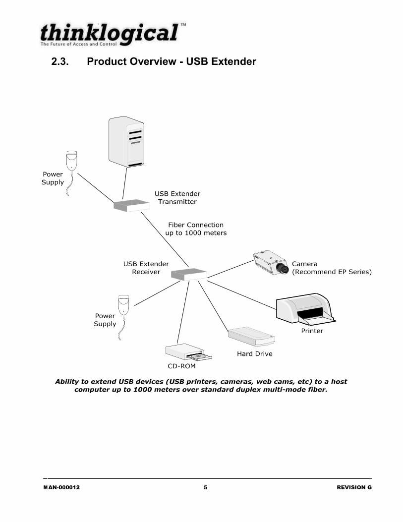
3.1.2. Receiver LED Label Status Power LED is ON (solid green) when power supply is properly connected Device Ports labeled 1, 2, 3, 4
LED is ON (solid green) when the device(s) is (are) properly connected and once the unit enumerates
Link Shows the status of the connection LED is ON (solid green) when the Power, device port(s), and Fiber are properly connected LED is BLINKING (blinking green) when the Fiber are properly connected and until the Host enumerates

MAN-000012 15 REVISION G
Product: Firewire 800 Extender

MAN-000012 16 REVISION G
1. Introduction 1.1. Contents
1.1.1. Firewire (1394b) When you receive your Thinklogical™ 1394b Extender, you should find the following items:
1394b Extender – Transmitter 1394b Extender – Receiver AC Power Supply (PWR-000033-R) – Quantity 2 AC Power Cord (PWR-000008-R) – Quantity 2 1394 Bilingual to 6 Pin 1394, 6 Feet (CBL000100-006FR) – Quantity 2 1394 Beta to Beta 9 Pin, 6 Feet (CBL000101-006FR) – Quantity 2 USB and 1394b Extender Product Manual
1.1.2. Firewire (1394b) Extender All models listed are available from Thinklogical™: FIR-000001-SCTX 1394b EXTENDER TRANSMITTER WITH SC FIR-000001-SCRX 1394b EXTENDER RECEIVER WITH SC FIR-000001-STTX 1394b EXTENDER TRANSMITTER WITH ST FIR-000001-STRX 1394b EXTENDER RECEIVER WITH ST
1.2. Laser Information
LASER RADIATIONDO NOT VIEW DIRECTLY WITH OPTICAL
INSTRUMENTS
CAUTION: In order to avoid possible exposure to laser energy, it is good practice to attach the fiber optic cables prior to applying power to the Firewire EXTENDER. If the fiber optic cable should become disconnected, DO NOT attempt to look into the cable or the panel mounted connector.

MAN-000012 17 REVISION G
2. System Features 2.1. General System Features
Extends Firewire 800 (1394b) connection up to 1000 meters (3280 feet) Compliant with IEEE 1394a (400) & IEEE 1394b (800) Installation is Plug-and-Play, no adjustments are necessary Uses standard duplex multi-mode fiber optic cable LEDs provide link performance status Available with your choice of ST or SC fiber connectors
2.2. Technical Specifications Storage Temperature -20 to 85 °C (-4 to 185 °F)
Supply Voltage 12 VDC ±5%. Adapter has Universal AC Power Input
Polarity: Positive Tip
Power Consumption P/N: PWR-000033-R (12V 5.5A Desktop Power Supply) 6 Watt Minimum; 36 Watt Maximum
Laser Output Specifications Meets Laser Class 1M Specifications
Panel Connectors *Note: 1394b connectors are rated
at 1.5A per connector
Transmitter: (2) 1394b connectors (1) Dual Fiber connector (SC or ST) (1) 2.5mm power connector
Receiver: (2) 1394b connectors (1) Dual Fiber connector (SC or ST)
(1) 2.0mm power connector
Optical Cable Duplex Fiber, multi-mode, 50 micron or 62.5 micron. (Fiber Cable is either customer-supplied or can be ordered from Thinklogical.)
Operating Temperature and Humidity
0 to 50 °C (32 to 122 °F); 10 to 95% RH, non-condensing
Enclosure Dimensions 6.61in x 4.00in x 1.09in (167.89mm x 101.60mm x 27.61mm) Tolerance: ± 0.039in (1mm)
Weight 1lb (0.45kg) each
Shipping Weight Transmitter and Receiver: 4lbs (1.81kg)
Copper Cables (2) 1394 Bilingual to 6 Pin 1394, 6 Feet Part Number: CBL000100-006FR
(2) 1394 Beta to Beta, 6 Feet Part Number: CBL000101-006FR

MAN-000012 18 REVISION G
2.3. Product Overview – Firewire 800 Extender
CCD Camera
CCD Camera

MAN-000012 19 REVISION G
2.3.1. Firewire 800 Transmitter
12V DC
POWER LINKT R
Transmitter
IEEE-1394b Fiber Optic Extension System800Firewire Extender
The Future of Access and Control
Model Firewire 800
CABLE
POWER
CABLE
POWER

MAN-000012 20 REVISION G
2.3.2. Firewire 800 Receiver
12V DC
POWER LINKT R
Receiver
IEEE-1394b Fiber Optic Extension System800Firewire Extender
The Future of Access and Control
Model Firewire 800
CABLE
POWER
CABLE
POWER

MAN-000012 21 REVISION G
2.3.3. Cables
2.3.3.1. Fiber Optic Cables When connecting the fiber optic cables, you must be sure to:
Connect the fiber connector labeled „T‟ on the Transmitter to the fiber connector
labeled „R‟ on the Receiver. Connect the fiber connector labeled „R‟ on the Transmitter to the fiber connector
labeled „T‟ on the Receiver.
*Note: Place Transmitter and Receiver units with the fiber panels facing each other. When you connect the fibers, THE FIBER CABLE SHOULD NOT BE CROSSED.
2.3.3.2. USB Type A – Receiver
2.3.3.3. USB Type B – Transmitter
2 Fibers
Up to 1000 meters

MAN-000012 22 REVISION G
2.3.4. Power Supply – PWR-000033-R (Quantity 2)
Universal Input: 90 – 264 VAC Continuous Short Circuit Protection Meets EN55022 Class “B”, Conducted High Efficiency, 85% Typical

MAN-000012 23 REVISION G
3. Installation
1. Plug fiber into T location labeled on the Transmitter unit. Plug that corresponding end of fiber into R location labeled on the Receiver unit.
2. Plug fiber into R location labeled on the Transmitter unit. Plug that corresponding end of fiber
into T location labeled on the Receiver unit.
3. Connect the power supply to the Receiver and plug corresponding end into a suitable AC power source.
4. Connect your PC to one of the Firewire locations on the Transmitter unit.
a. Connect your local Firewire device (if applicable) to the other Cable Link location (Firewire Connector) labeled on the Transmitter unit.
5. Connect the power supply to the Transmitter and plug corresponding end into a suitable AC
power source (OPTIONAL, depending on your power consumption)
6. Connect your devices(s) into the device port(s) ( Firewire Connectors) on the Receiver unit. Note: Please allow up to one minute for the CPU to recognize the Firewire system. Your Firewire 800 Extender System is now properly connected.

MAN-000012 24 REVISION G
3.1. LED Status
3.1.1. Transmitter
LED Label Status Power LED is ON (solid green) when power supply is properly connected and
sufficient power is provided. LED is OFF when power consumption is too high and the supplied power supply is necessary.
Link Shows the status of the connection. LED is ON (solid green) when fiber are properly connected.
Cable Power LED is ON (solid green) when enough power is supplied. LED is OFF when power consumption is too high and the supplied power supply is necessary.
3.1.2. Receiver LED Label Status Power LED is ON (solid green) when power supply is properly connected and
sufficient power is provided.
Link Shows the status of the connection. LED is ON (solid green) when fiber are properly connected.
Cable Power LED is ON (solid green) when power is properly connected.

MAN-000012 25 REVISION G
Product Identification
1. Markings
1.1. Product Serial Number The USB and FIREWIRE EXTENDER products have a unique serial number, imprinted on a small silver label that is placed on the bottom of the chassis. The serial number includes a date-code. The format for the date-code is two digits for the month; two digits for the day and four digits for the year and two or three digits for a unique unit number. This serial number is also found on the original shipping carton.
1.2. Symbols Found on Product Markings and labels on the product follow industry-standard conventions. Regulatory markings found on the products comply with requirements.

MAN-000012 26 REVISION G
Safety Standards
1. Laser Module Approval standard and any approvals it carries:
Class 1 Laser Safety per FDA/CDRH and EN60825-1 Electrical Safety per EN60950 Certified by TUV and CSA
2. External Fiber Connector
Flammability Rating UL94V0
3. USB 1.1 and 2.0 Power Supply
Thinklogical™ Part Number: PWR-000022-R
UL File Number: E176177
4. Firewire 800 Power Supply
Thinklogical™ Part Number: PWR-000033-R UL File Number: E176177

MAN-000012 27 REVISION G
How to Contact Us
1. Customer Support Thank you to our customers for choosing a Thinklogical™ product for your application. We appreciate your business and are interested in helping you successfully use our product. Thinklogical™ is here to help you. To contact Thinklogical™, use the following telephone numbers and internet-based methods.
1.1. Website Check out our website for current product offerings, support information and general information about all of the Thinklogical™ we offer. Our internet website offers product information on all current systems, including technical specification sheets and installation guides (for viewing online or for download), product diagrams showing physical connections and other information you might need. We are constantly updating our website, so be sure to “refresh” your browser when visiting the Thinklogical™ website to see the most up-to-date information.
Internet: www.thinklogical.com *NOTE: Most online documents are stored as Adobe Acrobat “PDF” files. If you do not have the Adobe Acrobat reader needed to view PDF files, visit www.adobe.com for a download.
1.2. Email Thinklogical™ is staffed Monday through Friday from 8:30am to 5:30pm, Eastern Time Zone. We will try to respond to your email inquiries promptly, use the following email addresses for your different needs: [email protected] – Information on Thinklogical™and our products. [email protected] – Sales Department - orders, questions or issues. [email protected] – Product support, technical issues or questions, product repairs and request for Return Authorization.

MAN-000012 28 REVISION G
1.3. Telephone Telephone Sales: Contact our expert technically oriented sales staff via telephone in Milford, CT at (203) 647-8700 or if in the continental US, you may use our toll-free number (800) 291-3211. We are here Monday through Friday from 9:00am to 5:00pm, Eastern Time Zone. Ask for their direct dial phone number when you call. Telephone Product Support: Contact Product Support via telephone in Milford, CT at (203) 647-8700. The support lines are manned Monday through Friday, 9am to 5pm, Eastern Time Zone. International Sales: Please contact our US sales staff in Milford, CT at (203) 647-8700. We are here Monday through Friday, 8:30am to 5:30pm, Eastern Time Zone (same as New York City). If leaving a voice message, please provide a “best time to call back” so we may reach you at your convenience. Our switchboard attendant will direct your call during regular business hours. We have an automated attendant answering our main telephone switchboard after regular business hours and holidays. You can leave voice messages for individuals at any time. Our Sales Representatives have direct numbers to speed up your next call to us.
1.4. Fax Our company facsimile number is (203) 783-9949. Please indicate the nature of the fax on your cover sheet and provide return contact information.

MAN-000012 29 REVISION G
2. Product Support Thinklogical‟s support personnel are available Monday through Friday from 8:30am to 5:30pm, Eastern Time Zone. If your application might require assistance at some time outside of our normal business hours, please contact us beforehand and we will do our best to make arrangements to help you with your Thinklogical™ products.
2.1. Warranty Thinklogical, LLC (“Thinklogical”) warrants this product against defects in materials and workmanship for a period of one (1) year from the date of delivery (ordinary wear and tear excluded). This limited warranty does not cover defects resulting from (i) use of the product other than as described in the applicable documentation for the product; (ii) modifications to or repairs of the product that are made by any party other than Thinklogical or a party acting on Thinklogical‟s behalf, or (iii) combination of the product with third party products that is not consented to by Thinklogical. Occurrences of events described in (i) – (iii) shall void the foregoing warranty. This warranty gives you specific legal rights, and you may also have other rights which vary from state to state.
Except for the express warranty set forth above, to the fullest extent permitted under applicable law, Thinklogical, LLC and its suppliers disclaim any and all other warranties, express and implied, including without limitation the implied warranties of merchantability, fitness for a particular purpose, title and non-infringement.
If the defective product is returned to the authorized dealer within one (1) year of the delivery date, repair or replacement of the product will be made. Repairs may be made with refurbished parts. If repair or replacement is not possible, Thinklogical may keep the defective product and refund the amount that you paid for the defective product. These are Thinklogical‟s sole obligations, and your exclusive remedies, for a breach of the limited warranty set forth above.
To return a defective product, contact the Thinklogical authorized dealer from whom you purchased the product. Do not return a product directly to Thinklogical without prior authorization from your dealer.
If you have received prior authorization from your dealer and are returning a product directly to Thinklogical:
1. Contact your sales representative, or call Customer Support at (800)291–3211 or + (203)647–8700.
2. Describe the defect with the product and Customer Support will issue a Return Merchandise Authorization Number (RMA#).
3. Pack the product in all of its original packing, if possible, and write the RMA number on the box. 4. Return the product to:
Thinklogical, LLC Attn: RMA# [Insert the RMA# issued to you, by Thinklogical, here.] 100 Washington Street Milford, CT 06460 USA
MAN-000012 30 REVISION G
2.2. Our Address If you have any issue with the product, have product questions or need technical assistance with your USB or FIREWIRE EXTENDER system, please call us at (203) 647-8700 and let us help. If shipping something with an RA # or if you‟d like to write us, we are located at:
Thinklogical™ Inc. 100 Washington Street Milford, CT 06460 USA

MAN-000012 31 REVISION G
Appendix A - Dimensions 1. USB 1.1 and 2.0 Transmitter
Transmitter
USB 2.0 Hi-Speed Extension System
2.0USB EXTENDER
The Future of Access and Control
Model USB-2
HOST
5VDC
POWER LINKT R
3.0"(76.25mm)
6.11" (155.19mm)
5.61" (142.49mm)
6.61" (167.89mm)
1.09" (27.61mm)
.50" (12.70mm)
4.0"(101.60mm)
.25" (6.35mm) (4X)
.25" (6.35mm) Dia. (4X)
Tolerance: ± 0.039" (1mm)

MAN-000012 32 REVISION G
2. USB 1.1 and 2.0 Receiver
Receiver
1 2 3 4
5VDC
POWER LINKT R
4.0"
3.0"
6.11" (155.19mm)
6.61" (167.89mm)
.25" (6.35mm) Dia. (4X).50"
(12.70mm)
1.09" (27.61mm)
5.61" (142.49mm)
Receiver
USB 2.0 Hi-Speed Extension System
2.0USB EXTENDER
The Future of Access and Control
Model USB-2
.25" (6.35mm) (4X)
3.0"(76.25mm)
4.0"(101.60mm)
Tolerance: ± 0.039” (1mm)

MAN-000012 33 REVISION G
3. Firewire 800 Transmitter
12V DC
POWER LINKT R
CABLE
POWER
CABLE
POWER
Transmitter
IEEE-1394b Fiber Optic Extension System800Firewire Extender
The Future of Access and Control
Model Firewire 800
6.61" (167.89mm)
1.09" (27.61mm)
.25" (6.35mm) Dia. (4X)
.25" (6.35mm) (4X).50" (12.70mm)
5.61" (142.49mm)
6.11" (155.19mm)
3.0"(76.25mm)
4.0"(101.60mm)
Tolerance: ± 0.039" (1mm)

MAN-000012 34 REVISION G
4. Firewire 800 Receiver
Receiver
IEEE-1394b Fiber Optic Extension System800Firewire Extender
The Future of Access and Control
Model Firewire 800
12V DC
POWER LINKT R
CABLE
POWER
CABLE
POWER
6.61" (167.89mm)
1.09"(27.61mm)
.25" (6.35mm) Dia. (4X)
.25" (6.35mm) (4X).50" (12.70mm)
5.61" (142.49mm)
6.11" (155.19mm)
4.0"(101.60mm)
3.0"(76.25mm)
Tolerance: ± 0.039" (1mm)

MAN-000012 35 REVISION G
For Your Notes: