Embed Size (px)
Citation preview
Document: 327216-001
USB 3.0* Radio Frequency Interference Impact on 2.4 GHz Wireless Devices White Paper April 2012
2 White Paper
INFORMATION IN THIS DOCUMENT IS PROVIDED IN CONNECTION WITH INTEL PRODUCTS. NO LICENSE, EXPRESS OR IMPLIED, BY ESTOPPEL OR OTHERWISE, TO ANY INTELLECTUAL PROPERTY RIGHTS IS GRANTED BY THIS DOCUMENT. EXCEPT AS PROVIDED IN INTEL'S TERMS AND CONDITIONS OF SALE FOR SUCH PRODUCTS, INTEL ASSUMES NO LIABILITY WHATSOEVER AND INTEL DISCLAIMS ANY EXPRESS OR IMPLIED WARRANTY, RELATING TO SALE AND/OR USE OF INTEL PRODUCTS INCLUDING LIABILITY OR WARRANTIES RELATING TO FITNESS FOR A PARTICULAR PURPOSE, MERCHANTABILITY, OR INFRINGEMENT OF ANY PATENT, COPYRIGHT OR OTHER INTELLECTUAL PROPERTY RIGHT.
A "Mission Critical Application" is any application in which failure of the Intel Product could result, directly or indirectly, in personal injury or death. SHOULD YOU PURCHASE OR USE INTEL'S PRODUCTS FOR ANY SUCH MISSION CRITICAL APPLICATION, YOU SHALL INDEMNIFY AND HOLD INTEL AND ITS SUBSIDIARIES, SUBCONTRACTORS AND AFFILIATES, AND THE DIRECTORS, OFFICERS, AND EMPLOYEES OF EACH, HARMLESS AGAINST ALL CLAIMS COSTS, DAMAGES, AND EXPENSES AND REASONABLE ATTORNEYS' FEES ARISING OUT OF, DIRECTLY OR INDIRECTLY, ANY CLAIM OF PRODUCT LIABILITY, PERSONAL INJURY, OR DEATH ARISING IN ANY WAY OUT OF SUCH MISSION CRITICAL APPLICATION, WHETHER OR NOT INTEL OR ITS SUBCONTRACTOR WAS NEGLIGENT IN THE DESIGN, MANUFACTURE, OR WARNING OF THE INTEL PRODUCT OR ANY OF ITS PARTS.
Intel may make changes to specifications and product descriptions at any time, without notice. Designers must not rely on the absence or characteristics of any features or instructions marked "reserved" or "undefined". Intel reserves these for future definition and shall have no responsibility whatsoever for conflicts or incompatibilities arising from future changes to them. The information here is subject to change without notice. Do not finalize a design with this information.
The products described in this document may contain design defects or errors known as errata which may cause the product to deviate from published specifications. Current characterized errata are available on request.
Contact your local Intel sales office or your distributor to obtain the latest specifications and before placing your product order.
Copies of documents which have an order number and are referenced in this document, or other Intel literature, may be obtained at http://www.intel.com/design/literature.htm.
Intel and the Intel logo are trademarks of Intel Corporation in the U.S. and other countries.
*Other names and brands may be claimed as the property of others.
Copyright © 2012, Intel Corporation. All rights reserved.
White Paper 3
Contents 1 Introduction ...................................................................................................... 6
2 Overview .......................................................................................................... 7 2.1 2.4 GHz Wireless Devices ......................................................................... 7 2.2 USB 3.0* ............................................................................................... 7
3 Impact of USB 3.0* Noise ................................................................................... 9 3.1 Interoperability Issue .............................................................................. 9 3.2 Impact to Wireless Device Performance .................................................... 11
4 Mitigation Methods ............................................................................................ 13 4.1 Shielding the USB 3.0* Peripheral Device ................................................. 13 4.2 Improving Shielding on the Notebook USB 3.0* Connector .......................... 15 4.3 Wireless Antenna Placement .................................................................... 18
5 Performance Improvement ................................................................................ 20
6 Summary ........................................................................................................ 21
7 Acknowledgement ............................................................................................. 22
4 White Paper
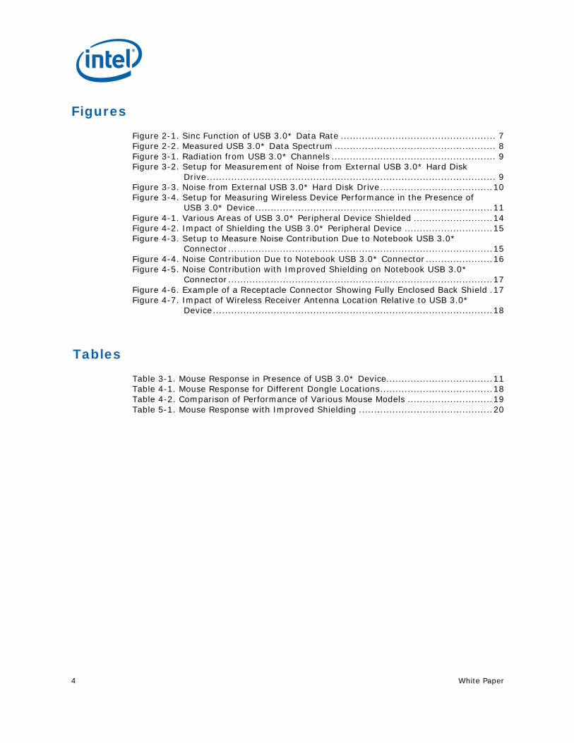
Figures
Figure 2-1. Sinc Function of USB 3.0* Data Rate ................................................... 7 Figure 2-2. Measured USB 3.0* Data Spectrum ..................................................... 8 Figure 3-1. Radiation from USB 3.0* Channels ...................................................... 9 Figure 3-2. Setup for Measurement of Noise from External USB 3.0* Hard Disk
Drive ............................................................................................... 9 Figure 3-3. Noise from External USB 3.0* Hard Disk Drive ..................................... 10 Figure 3-4. Setup for Measuring Wireless Device Performance in the Presence of
USB 3.0* Device .............................................................................. 11 Figure 4-1. Various Areas of USB 3.0* Peripheral Device Shielded .......................... 14 Figure 4-2. Impact of Shielding the USB 3.0* Peripheral Device ............................. 15 Figure 4-3. Setup to Measure Noise Contribution Due to Notebook USB 3.0*
Connector ....................................................................................... 15 Figure 4-4. Noise Contribution Due to Notebook USB 3.0* Connector ...................... 16 Figure 4-5. Noise Contribution with Improved Shielding on Notebook USB 3.0*
Connector ....................................................................................... 17 Figure 4-6. Example of a Receptacle Connector Showing Fully Enclosed Back Shield . 17 Figure 4-7. Impact of Wireless Receiver Antenna Location Relative to USB 3.0*
Device ............................................................................................ 18
Tables
Table 3-1. Mouse Response in Presence of USB 3.0* Device ................................... 11 Table 4-1. Mouse Response for Different Dongle Locations ..................................... 18 Table 4-2. Comparison of Performance of Various Mouse Models ............................ 19 Table 5-1. Mouse Response with Improved Shielding ............................................ 20
White Paper 5
Revision History
Revision Number
Description Revision Date
001 • Initial release. April 2012
§ §
Introduction
6 White Paper
1 Introduction The purpose of this document is to create an awareness of radio frequency interference to wireless devices operating in the 2.4 GHz ISM band as a result of certain USB 3.0* devices and cables. This is a guide to customers of the USB 3.0 RFI mitigation options that are available.
§ §
Overview
White Paper 7
2 Overview
2.1 2.4 GHz Wireless Devices The 2.4 GHz ISM band is a widely used unlicensed radio frequency band for devices such as wireless routers, as well as wireless PC peripherals such as a mouse or keyboard. These devices may use standard protocols such as the IEEE 802.11b/g/n or Bluetooth, or they may use proprietary protocols. The radios may use frequency hopping, frequency agility, or may operate on a fixed frequency.
In order for a wireless radio receiver to detect the received signal correctly, the received signal power must be greater than the sensitivity of the radio. The sensitivity limit of the receiver is influenced by the minimum signal-to-noise ratio (SNR) required for demodulation. The receiver sensitivity, transmitted signal power, receive and transmit antenna gain, and wireless link path loss dictate the achievable wireless range by determining the signal and noise power at the receiver.
As the distance between a transmitter and receiver is increased, the signal power at the receiver input decreases. At the same time, the increased presence of broadband noise in the longer link will decrease the actual signal-to-noise ratio at the receiver. This reduces the wireless range. The reduction of the available SNR at the receiver requires an increase in the minimum signal level to overcome the sensitivity limit of the receiver.
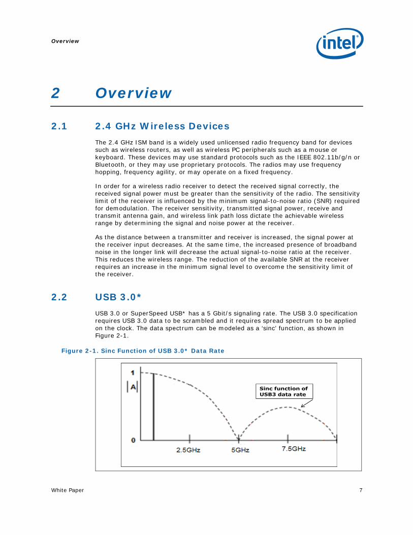
2.2 USB 3.0* USB 3.0 or SuperSpeed USB* has a 5 Gbit/s signaling rate. The USB 3.0 specification requires USB 3.0 data to be scrambled and it requires spread spectrum to be applied on the clock. The data spectrum can be modeled as a ‘sinc’ function, as shown in Figure 2-1.
Figure 2-1. Sinc Function of USB 3.0* Data Rate
Overview
8 White Paper
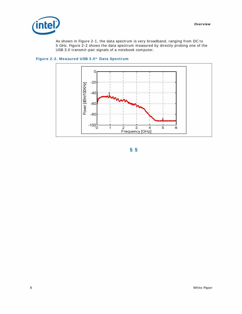
As shown in Figure 2-1, the data spectrum is very broadband, ranging from DC to 5 GHz. Figure 2-2 shows the data spectrum measured by directly probing one of the USB 3.0 transmit-pair signals of a notebook computer.
Figure 2-2. Measured USB 3.0* Data Spectrum
§ §
Impact of USB 3.0* Noise
White Paper 9
3 Impact of USB 3.0* Noise
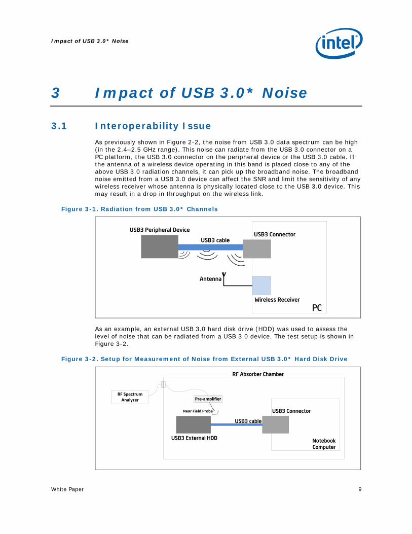
3.1 Interoperability Issue As previously shown in Figure 2-2, the noise from USB 3.0 data spectrum can be high (in the 2.4–2.5 GHz range). This noise can radiate from the USB 3.0 connector on a PC platform, the USB 3.0 connector on the peripheral device or the USB 3.0 cable. If the antenna of a wireless device operating in this band is placed close to any of the above USB 3.0 radiation channels, it can pick up the broadband noise. The broadband noise emitted from a USB 3.0 device can affect the SNR and limit the sensitivity of any wireless receiver whose antenna is physically located close to the USB 3.0 device. This may result in a drop in throughput on the wireless link.
Figure 3-1. Radiation from USB 3.0* Channels
Wireless dongle
PC
USB3 ConnectorUSB3 cable
Wireless Receiver
USB3 Peripheral Device
Antenna
As an example, an external USB 3.0 hard disk drive (HDD) was used to assess the level of noise that can be radiated from a USB 3.0 device. The test setup is shown in Figure 3-2.
Figure 3-2. Setup for Measurement of Noise from External USB 3.0* Hard Disk Drive
Wireless dongle
USB3 Connector
USB3 cable
USB3 External HDD Notebook Computer
RF Absorber Chamber
Pre-amplifierRF Spectrum
Analyzer
Near Field Probe
Impact of USB 3.0* Noise
10 White Paper
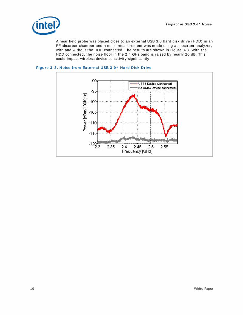
A near field probe was placed close to an external USB 3.0 hard disk drive (HDD) in an RF absorber chamber and a noise measurement was made using a spectrum analyzer, with and without the HDD connected. The results are shown in Figure 3-3. With the HDD connected, the noise floor in the 2.4 GHz band is raised by nearly 20 dB. This could impact wireless device sensitivity significantly.
Figure 3-3. Noise from External USB 3.0* Hard Disk Drive
Impact of USB 3.0* Noise
White Paper 11
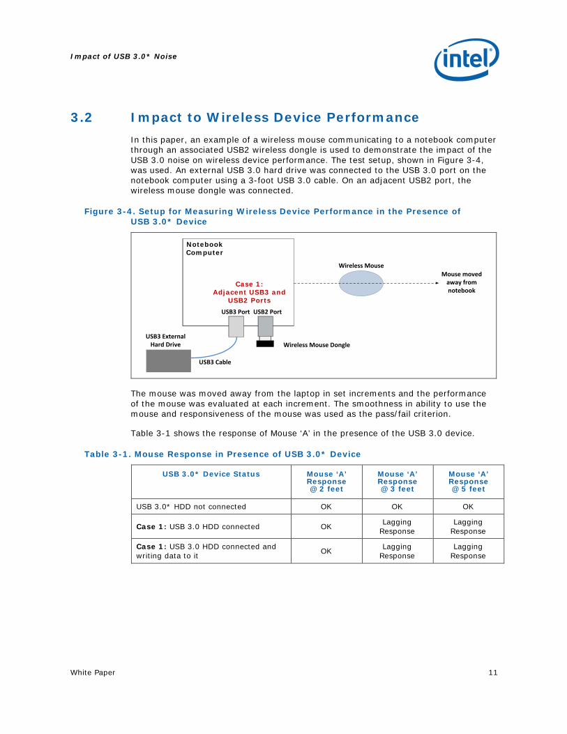
3.2 Impact to Wireless Device Performance In this paper, an example of a wireless mouse communicating to a notebook computer through an associated USB2 wireless dongle is used to demonstrate the impact of the USB 3.0 noise on wireless device performance. The test setup, shown in Figure 3-4, was used. An external USB 3.0 hard drive was connected to the USB 3.0 port on the notebook computer using a 3-foot USB 3.0 cable. On an adjacent USB2 port, the wireless mouse dongle was connected.
Figure 3-4. Setup for Measuring Wireless Device Performance in the Presence of USB 3.0* Device
Notebook Computer
USB3 Port USB2 Port
Wireless Mouse DongleUSB3 External
Hard Drive
USB3 Cable
Wireless Mouse Mouse moved
away from notebook
Case 1: Adjacent USB3 and
USB2 Ports
The mouse was moved away from the laptop in set increments and the performance of the mouse was evaluated at each increment. The smoothness in ability to use the mouse and responsiveness of the mouse was used as the pass/fail criterion.
Table 3-1 shows the response of Mouse ‘A’ in the presence of the USB 3.0 device.
Table 3-1. Mouse Response in Presence of USB 3.0* Device
USB 3.0* Device Status Mouse ‘A’ Response @ 2 feet
Mouse ‘A’ Response @ 3 feet
Mouse ‘A’ Response @ 5 feet
USB 3.0* HDD not connected OK OK OK
Case 1: USB 3.0 HDD connected OK Lagging Response
Lagging Response
Case 1: USB 3.0 HDD connected and writing data to it OK Lagging
Response Lagging
Response
Impact of USB 3.0* Noise
12 White Paper
As shown in Table 3-1, there is degradation in the performance of the wireless mouse when a USB 3.0 device is connected to the notebook computer. At a distance of 3 feet and greater away from the notebook computer, a significant lag was experienced in the response of the mouse. The impact to mouse performance was found to be the same whether the USB 3.0 peripheral device had data being actively written to it or if it was merely connected to the notebook computer and the link to it established.
A similar impact to wireless mouse performance was noted if a USB 3.0 device, such as a flash drive, was used. Since the noise from the USB 3.0 is broadband, it could potentially impact any radio whose antenna is close by. Although the test results are not shown in this paper, similar impact was seen to Bluetooth radio performance.
§ §
Mitigation Methods
White Paper 13
4 Mitigation Methods There are several areas where improvements can be made to minimize the impact of USB 3.0 noise on wireless device performance. Three areas where improvements can be made are:
• Shielding on the USB 3.0 peripheral device
• Shielding improvements on the USB 3.0 receptacle connector on the notebook
• Wireless antenna placement, wireless receiver performance
Each of these areas are studied in further detail in the following sections.
4.1 Shielding the USB 3.0* Peripheral Device As previously described in Section 3.1, noise due to the USB 3.0 data spectrum can radiate from a USB 3.0 peripheral device and its connector. Properly shielding the USB 3.0 peripheral device can help reduce the amount of noise emitted in the 2.4 GHz band. To illustrate this point, different areas of an external HDD were shielded, and for each case, noise emitted into the 2.4 GHz band was measured. The test setup used for this measurement is the same as in Figure 3-2.
Mitigation Methods
14 White Paper
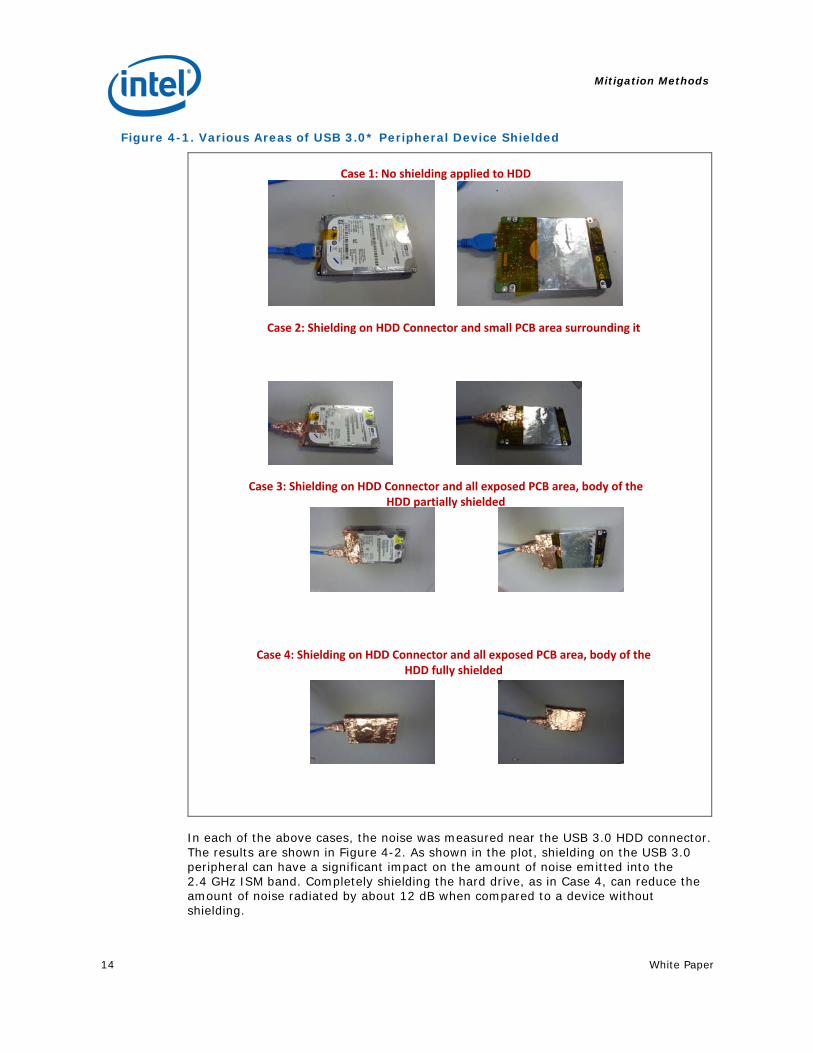
Figure 4-1. Various Areas of USB 3.0* Peripheral Device Shielded
Case 1: No shielding applied to HDD
Case 2: Shielding on HDD Connector and small PCB area surrounding it
Case 3: Shielding on HDD Connector and all exposed PCB area, body of the HDD partially shielded
Case 4: Shielding on HDD Connector and all exposed PCB area, body of the HDD fully shielded
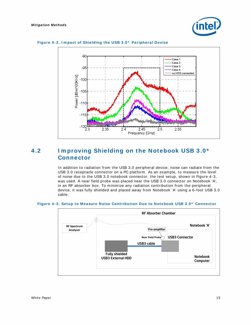
In each of the above cases, the noise was measured near the USB 3.0 HDD connector. The results are shown in Figure 4-2. As shown in the plot, shielding on the USB 3.0 peripheral can have a significant impact on the amount of noise emitted into the 2.4 GHz ISM band. Completely shielding the hard drive, as in Case 4, can reduce the amount of noise radiated by about 12 dB when compared to a device without shielding.
Mitigation Methods
White Paper 15
Figure 4-2. Impact of Shielding the USB 3.0* Peripheral Device
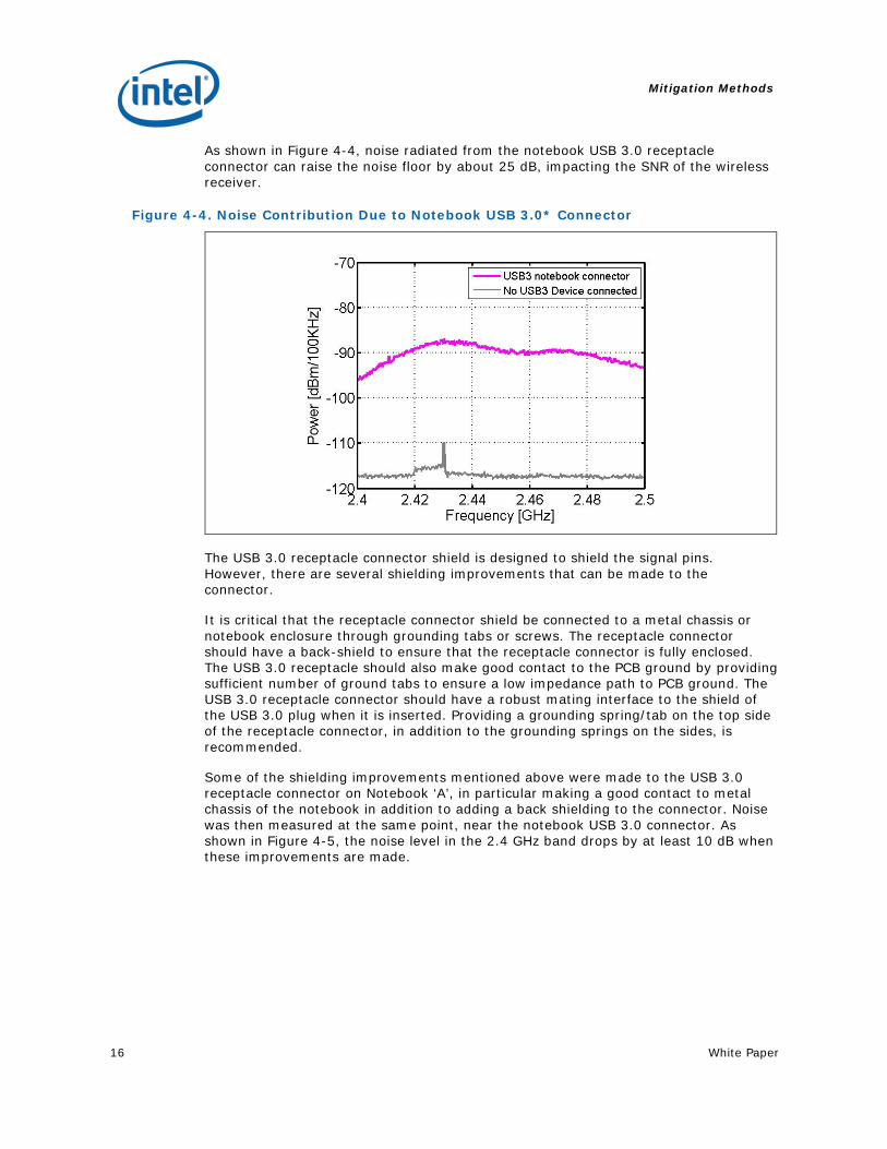
4.2 Improving Shielding on the Notebook USB 3.0* Connector In addition to radiation from the USB 3.0 peripheral device, noise can radiate from the USB 3.0 receptacle connector on a PC platform. As an example, to measure the level of noise due to the USB 3.0 notebook connector, the test setup, shown in Figure 4-3, was used. A near field probe was placed near the USB 3.0 connector on Notebook ‘A’, in an RF absorber box. To minimize any radiation contribution from the peripheral device, it was fully shielded and placed away from Notebook ‘A’ using a 6-foot USB 3.0 cable.
Figure 4-3. Setup to Measure Noise Contribution Due to Notebook USB 3.0* Connector
Wireless dongle
USB3 Connector
USB3 cable
Fully shieldedUSB3 External HDD Notebook
Computer
RF Absorber Chamber
Pre-amplifierRF Spectrum
Analyzer
Near Field Probe
Notebook ‘A’
Mitigation Methods
16 White Paper
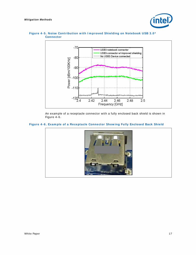
As shown in Figure 4-4, noise radiated from the notebook USB 3.0 receptacle connector can raise the noise floor by about 25 dB, impacting the SNR of the wireless receiver.
Figure 4-4. Noise Contribution Due to Notebook USB 3.0* Connector
The USB 3.0 receptacle connector shield is designed to shield the signal pins. However, there are several shielding improvements that can be made to the connector.
It is critical that the receptacle connector shield be connected to a metal chassis or notebook enclosure through grounding tabs or screws. The receptacle connector should have a back-shield to ensure that the receptacle connector is fully enclosed. The USB 3.0 receptacle should also make good contact to the PCB ground by providing sufficient number of ground tabs to ensure a low impedance path to PCB ground. The USB 3.0 receptacle connector should have a robust mating interface to the shield of the USB 3.0 plug when it is inserted. Providing a grounding spring/tab on the top side of the receptacle connector, in addition to the grounding springs on the sides, is recommended.
Some of the shielding improvements mentioned above were made to the USB 3.0 receptacle connector on Notebook ‘A’, in particular making a good contact to metal chassis of the notebook in addition to adding a back shielding to the connector. Noise was then measured at the same point, near the notebook USB 3.0 connector. As shown in Figure 4-5, the noise level in the 2.4 GHz band drops by at least 10 dB when these improvements are made.
Mitigation Methods
White Paper 17
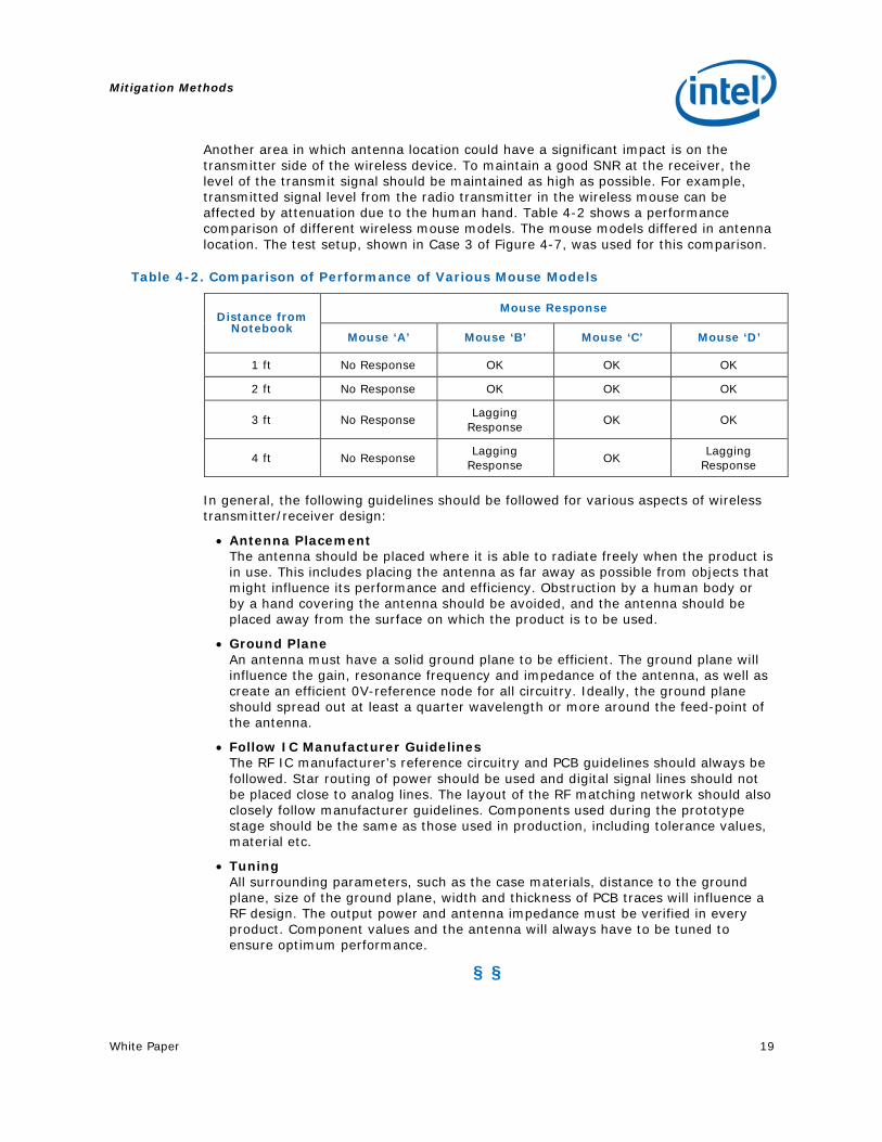
Figure 4-5. Noise Contribution with Improved Shielding on Notebook USB 3.0* Connector
An example of a receptacle connector with a fully enclosed back shield is shown in Figure 4-6.
Figure 4-6. Example of a Receptacle Connector Showing Fully Enclosed Back Shield

Mitigation Methods
18 White Paper
4.3 Wireless Antenna Placement To assess the impact of the location of the wireless receiver antenna with respect to the USB 3.0 port/device, the following changes were made to the test setup in Figure 3-4. For Case 2 in Figure 4-7, the wireless dongle was moved away from the USB 3.0 device and port using a USB2 extension cable, placing the dongle on the opposite side of the notebook computer. In Case 3, the wireless dongle was connected to a USB 2.0 port that was stacked above the USB 3.0 port. In both Cases 2 and 3, a flash drive was used as the peripheral device.
Figure 4-7. Impact of Wireless Receiver Antenna Location Relative to USB 3.0* Device
Notebook Computer
USB3 Port USB2 Port
Wireless Mouse Dongle
USB3 Flash Drive
Case 2: Wireless Dongle moved
away using USB2 extension cable
Notebook Computer
Wireless Mouse Dongle
Case 3: Vertically Stacked
USB3 and USB2 Ports
USB3 Flash Drive
Mouse performance in these two cases is shown in Table 4-1.
Table 4-1. Mouse Response for Different Dongle Locations
USB 3.0* Device Status Mouse ‘A’ Response @ 2 feet
Mouse ‘A’ Response @ 3 feet
Mouse ‘A’ Response @ 5 feet
Case 2: Wireless dongle placed on opposite side of USB 3.0* port OK OK OK
Case 3: Wireless mouse dongle stacked vertically above USB 3.0 port No Response No Response No Response
As shown in Table 4-1 above, the location of the wireless receiver antenna relative to the USB 3.0 device/port has a significant impact on the performance of the wireless device. Placing the wireless antenna away from the USB 3.0 ports and device can reduce the impact of noise, even though it does not eliminate it completely. Based on the receiver characteristics, an optimum location for the antenna should be found.
Mitigation Methods
White Paper 19
Another area in which antenna location could have a significant impact is on the transmitter side of the wireless device. To maintain a good SNR at the receiver, the level of the transmit signal should be maintained as high as possible. For example, transmitted signal level from the radio transmitter in the wireless mouse can be affected by attenuation due to the human hand. Table 4-2 shows a performance comparison of different wireless mouse models. The mouse models differed in antenna location. The test setup, shown in Case 3 of Figure 4-7, was used for this comparison.
Table 4-2. Comparison of Performance of Various Mouse Models
Distance from Notebook
Mouse Response
Mouse ‘A’ Mouse ‘B’ Mouse ‘C’ Mouse ‘D’
1 ft No Response OK OK OK
2 ft No Response OK OK OK
3 ft No Response Lagging Response OK OK
4 ft No Response Lagging Response OK Lagging
Response
In general, the following guidelines should be followed for various aspects of wireless transmitter/receiver design:
• Antenna Placement The antenna should be placed where it is able to radiate freely when the product is in use. This includes placing the antenna as far away as possible from objects that might influence its performance and efficiency. Obstruction by a human body or by a hand covering the antenna should be avoided, and the antenna should be placed away from the surface on which the product is to be used.
• Ground Plane An antenna must have a solid ground plane to be efficient. The ground plane will influence the gain, resonance frequency and impedance of the antenna, as well as create an efficient 0V-reference node for all circuitry. Ideally, the ground plane should spread out at least a quarter wavelength or more around the feed-point of the antenna.
• Follow IC Manufacturer Guidelines The RF IC manufacturer’s reference circuitry and PCB guidelines should always be followed. Star routing of power should be used and digital signal lines should not be placed close to analog lines. The layout of the RF matching network should also closely follow manufacturer guidelines. Components used during the prototype stage should be the same as those used in production, including tolerance values, material etc.
• Tuning All surrounding parameters, such as the case materials, distance to the ground plane, size of the ground plane, width and thickness of PCB traces will influence a RF design. The output power and antenna impedance must be verified in every product. Component values and the antenna will always have to be tuned to ensure optimum performance.
§ §
Performance Improvement
20 White Paper
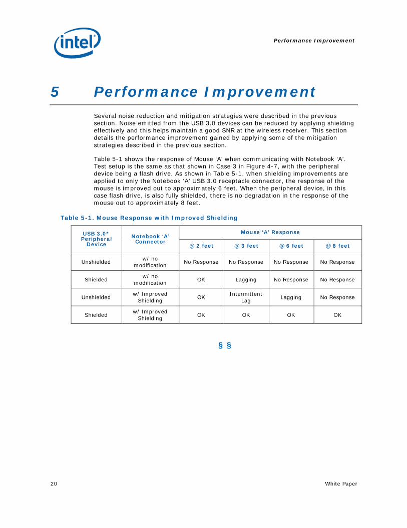
5 Performance Improvement Several noise reduction and mitigation strategies were described in the previous section. Noise emitted from the USB 3.0 devices can be reduced by applying shielding effectively and this helps maintain a good SNR at the wireless receiver. This section details the performance improvement gained by applying some of the mitigation strategies described in the previous section.
Table 5-1 shows the response of Mouse ‘A’ when communicating with Notebook ‘A’. Test setup is the same as that shown in Case 3 in Figure 4-7, with the peripheral device being a flash drive. As shown in Table 5-1, when shielding improvements are applied to only the Notebook ‘A’ USB 3.0 receptacle connector, the response of the mouse is improved out to approximately 6 feet. When the peripheral device, in this case flash drive, is also fully shielded, there is no degradation in the response of the mouse out to approximately 8 feet.
Table 5-1. Mouse Response with Improved Shielding
USB 3.0* Peripheral
Device Notebook ‘A’
Connector
Mouse ‘A’ Response
@ 2 feet @ 3 feet @ 6 feet @ 8 feet
Unshielded w/ no modification No Response No Response No Response No Response
Shielded w/ no modification OK Lagging No Response No Response
Unshielded w/ Improved Shielding OK Intermittent
Lag Lagging No Response
Shielded w/ Improved Shielding OK OK OK OK
§ §
Summary
White Paper 21
6 Summary The noise generated due to the USB 3.0 data spectrum can have an impact on radio receivers whose antenna is placed close to a USB 3.0 device and/or USB 3.0 connector. The noise is a broadband noise that cannot be filtered out, since it falls within the band of operation of the wireless device (2.4–2.5 GHz). The noise degrades the signal-to-noise ratio that the wireless receiver sees and limits its sensitivity. This then reduces the operating wireless range of the device.
Improving the shielding on the USB 3.0 receptacle connector can help reduce the amount of noise radiated due to USB 3.0 signaling. In addition, shielding of the USB 3.0 peripheral device plays an important role in reducing the amount of noise radiated in the 2.4–2.5 GHz range. This is particularly critical for peripheral devices that are placed close to the PC platform, such as a flash drive. Placement of the wireless antenna should also be carefully considered on a platform and be located as far away as possible from a USB 3.0 connector and/or device.
§ §
Acknowledgement
22 White Paper
7 Acknowledgement The authors would like to acknowledge Nordic Semiconductor for their inputs on the design guidelines for a wireless receiver/transmitter.
§ §