Embed Size (px)
Citation preview
USB 16 Relay Board Virtual Com Port Controlled - User Manual
04 Aug 2017
-1-
USB 16 Relay Board Virtual Com Port controlled
User Manual
Date: 04 Aug 2017
USB 16 Relay Board Virtual Com Port Controlled - User Manual
04 Aug 2017
-2-
Content
1. Specification ..................................................................................................... 3
2. Applications examples ..................................................................................... 3
3. Relay module overview .................................................................................... 4
4. USB port ........................................................................................................... 5
5. Relay contacts .................................................................................................. 6
6. Power connector .............................................................................................. 7
7. Drivers Installation ........................................................................................... 8
8. Protocol ............................................................................................................ 9
9. Software .......................................................................................................... 12
10. Appendix 1. Connections ............................................................................. 13
11. Appendix 2. PCB dimensions ...................................................................... 14
USB 16 Relay Board Virtual Com Port Controlled - User Manual
04 Aug 2017
-3-
1. Specification
16 x SPDT relays - 10A / 250VAC, 15A / 120VAC, 10A / 28VDC;
USB connector - type B
Power supply requirements, selectable during purchase: o 12V DC / 600mA o 24V DC / 400mA
Converter chipset: FT232RL
FT232RL optical isolation against communication noises
Communication: serial USB communication (Virtual Com Port)
Led-s: Relay Led, Power ON Led, USB ON Led, Rx Led, Tx Led
Operating temperature range: from -30ºC to +80ºC
PCB parameters : FR4 / 1.5mm / two layers / metalized holes / HAL / white stamp / solder mask / Extra PCB openings for better voltage isolation / Doubled PCB tracks for better voltage isolation
Dimensions: W=82mm x L=203mm x H=24mm
SKU: o DAE-CB/Ro16-12V-USB-PCB for 12VDC PCB version o DAE-CB/Ro16-24V-USB-PCB for 24VDC PCB version o DAE-CB/Ro16-12V-USB-BOX for 12VDC BOX version o DAE-CB/Ro16-24V-USB-BOX for 24VDC BOX version
2. Applications examples
Home automation
Industrial automation
Control electrical devices
USB 16 Relay Board Virtual Com Port Controlled - User Manual
04 Aug 2017
-4-
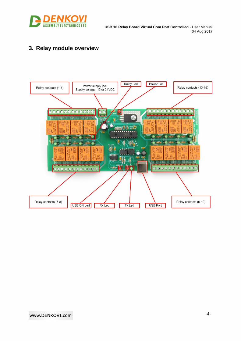
3. Relay module overview
USB 16 Relay Board Virtual Com Port Controlled - User Manual
04 Aug 2017
-5-
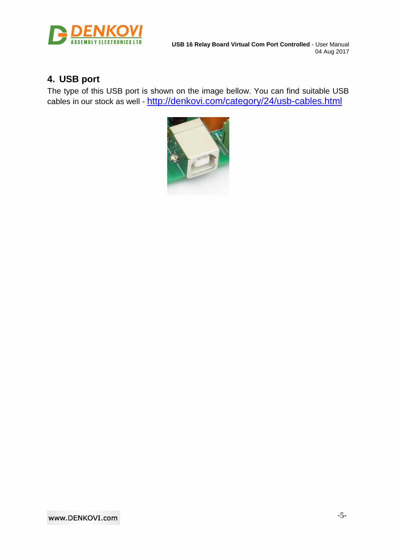
4. USB port
The type of this USB port is shown on the image bellow. You can find suitable USB
cables in our stock as well - http://denkovi.com/category/24/usb-cables.html
USB 16 Relay Board Virtual Com Port Controlled - User Manual
04 Aug 2017
-6-
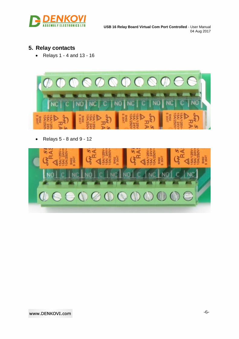
5. Relay contacts
Relays 1 - 4 and 13 - 16
Relays 5 - 8 and 9 - 12
USB 16 Relay Board Virtual Com Port Controlled - User Manual
04 Aug 2017
-7-
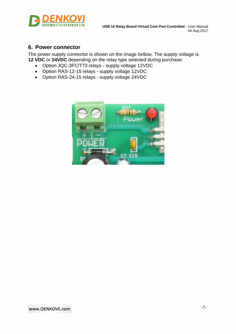
6. Power connector
The power supply connector is shown on the image bellow. The supply voltage is 12 VDC or 24VDC depending on the relay type selected during purchase:
Option JQC-3FC/T73 relays - supply voltage 12VDC
Option RAS-12-15 relays - supply voltage 12VDC
Option RAS-24-15 relays - supply voltage 24VDC
USB 16 Relay Board Virtual Com Port Controlled - User Manual
04 Aug 2017
-8-
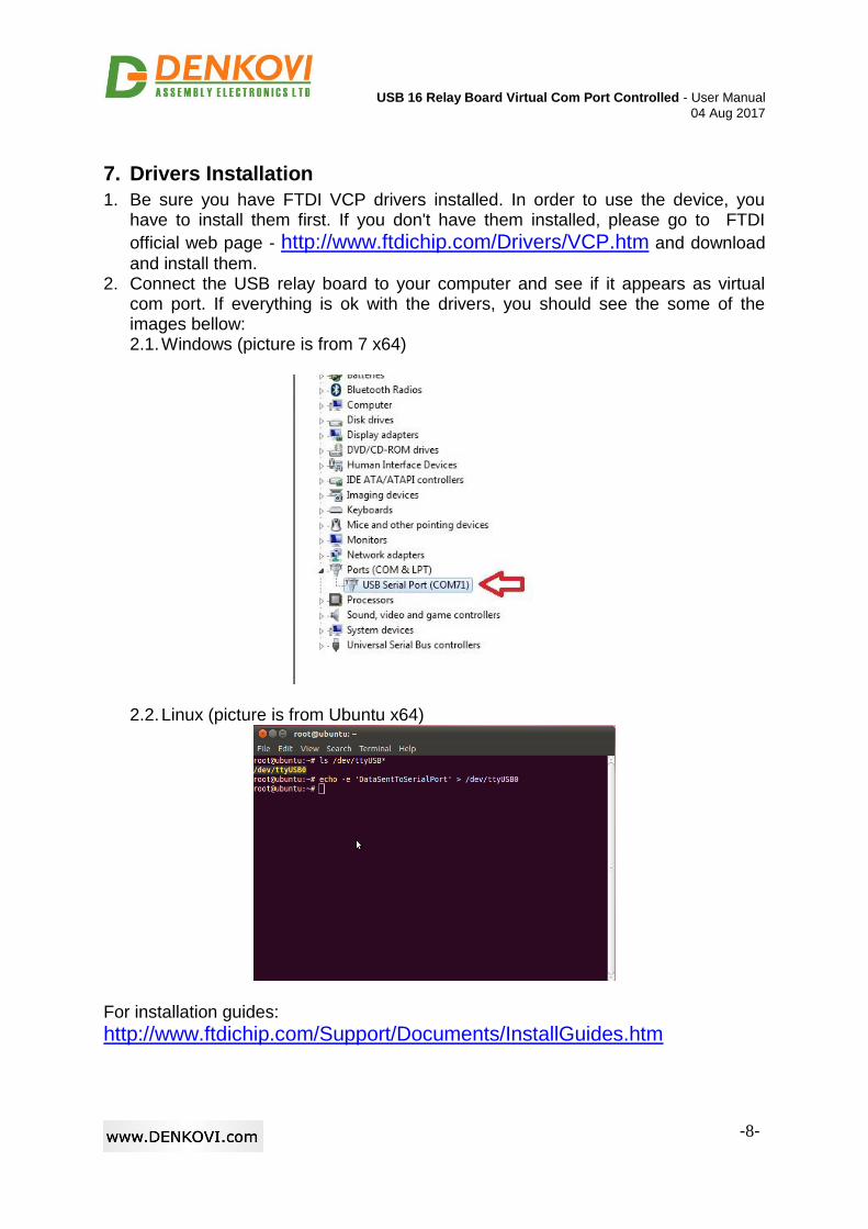
7. Drivers Installation
1. Be sure you have FTDI VCP drivers installed. In order to use the device, you have to install them first. If you don't have them installed, please go to FTDI
official web page - http://www.ftdichip.com/Drivers/VCP.htm and download
and install them. 2. Connect the USB relay board to your computer and see if it appears as virtual
com port. If everything is ok with the drivers, you should see the some of the images bellow: 2.1. Windows (picture is from 7 x64)
2.2. Linux (picture is from Ubuntu x64)
For installation guides:
http://www.ftdichip.com/Support/Documents/InstallGuides.htm
USB 16 Relay Board Virtual Com Port Controlled - User Manual
04 Aug 2017
-9-
8. Protocol
8.1. Serial Port parameters
Baud rate 9600 bps
Stop bit 1
Data bits 8
Parity No
8.2. Command for receiving relay status
Command format
Byte 1 Byte 2 Byte 3 Byte 4 Byte 5
'a' 's' 'k' '/' '/'
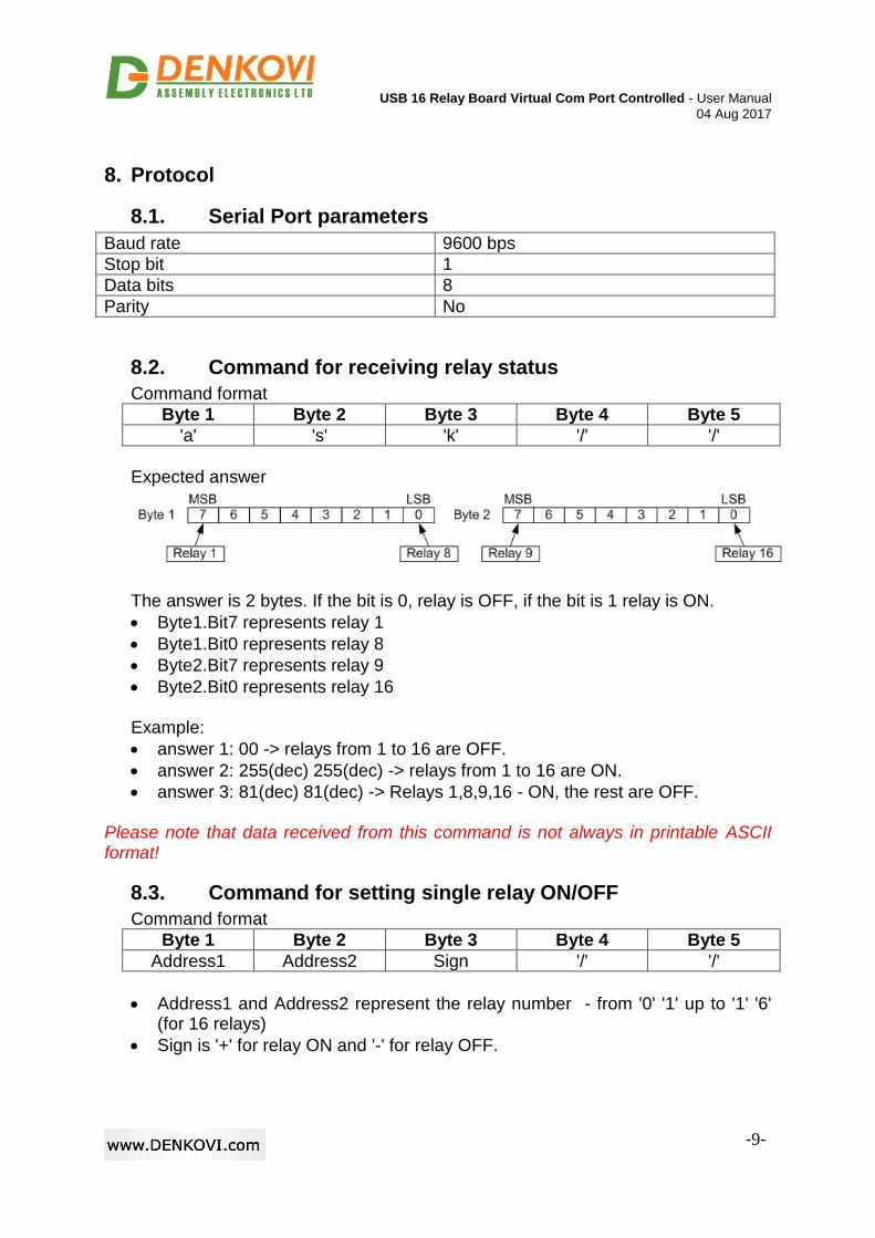
Expected answer
The answer is 2 bytes. If the bit is 0, relay is OFF, if the bit is 1 relay is ON.
Byte1.Bit7 represents relay 1
Byte1.Bit0 represents relay 8
Byte2.Bit7 represents relay 9
Byte2.Bit0 represents relay 16
Example:
answer 1: 00 -> relays from 1 to 16 are OFF.
answer 2: 255(dec) 255(dec) -> relays from 1 to 16 are ON.
answer 3: 81(dec) 81(dec) -> Relays 1,8,9,16 - ON, the rest are OFF.
Please note that data received from this command is not always in printable ASCII format!
8.3. Command for setting single relay ON/OFF
Command format
Byte 1 Byte 2 Byte 3 Byte 4 Byte 5
Address1 Address2 Sign '/' '/'
Address1 and Address2 represent the relay number - from '0' '1' up to '1' '6' (for 16 relays)
Sign is '+' for relay ON and '-' for relay OFF.
USB 16 Relay Board Virtual Com Port Controlled - User Manual
04 Aug 2017
-10-
Command format
Byte 1 Byte 2 Byte 3 Byte 4 Byte 5
Address1 Address2 Sign '/' '/'
Expected answer - if the command is successful, the answer is exactly the same like the command. Example:
"01-//" - Relay 1 is switched OFF
"12+//" - Relay 12 is switched ON
8.4. Command for setting all relays ON
Command format
Byte 1 Byte 2 Byte 3 Byte 4
'o' 'n' '/' '/'
Expected answer - if the command is successful, the answer is exactly the same like the command i.e. "on//". Example:
"on//" - all relays ON
8.5. Command for setting all relays OFF
Command format
Byte 1 Byte 2 Byte 3 Byte 4 Byte 5
'o' 'f' 'f' '/' '/'
Expected answer - if the command is successful, the answer is exactly the same like the command i.e. "off//". Example:
"off//" - all relays OFF
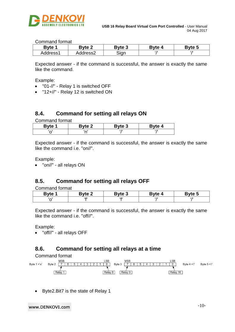
8.6. Command for setting all relays at a time
Command format
Byte2.Bit7 is the state of Relay 1
USB 16 Relay Board Virtual Com Port Controlled - User Manual
04 Aug 2017
-11-
Byte2.Bit0 is the state of Relay 8
Byte3.Bit7 is the state of Relay 9
Byte3.Bit0 is the state of Relay 16
If bit is 0, the relay state is OFF, if bit is 1 the relay state is ON Expected answer - if the command is successful, the answer is exactly the same like the command sent. Example: Send: 'x' 1A 05 '/' '/' 1A(hex)=00011010(bin) 05(hex)=00000101(bin) Relays 1,2,3,6,8,9,10,11,12,13,15 - switched OFF Relays 4,5,7,14,16 - switched ON
Please note that State1 and State2 are not always printable ASCII chars. These bytes are binary representation of the relays.
8.7. Additional information
Note that there must be minimum 5ms interval between every two commands !
USB 16 Relay Board Virtual Com Port Controlled - User Manual
04 Aug 2017
-12-
9. Software
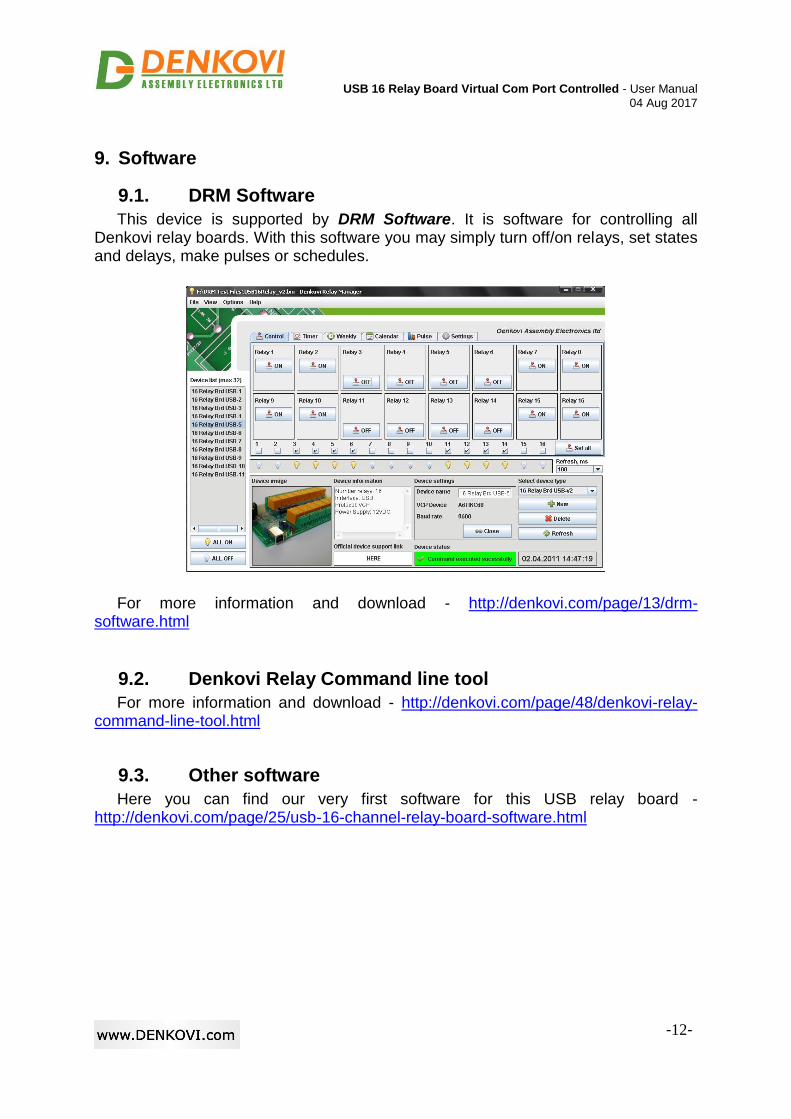
9.1. DRM Software
This device is supported by DRM Software. It is software for controlling all Denkovi relay boards. With this software you may simply turn off/on relays, set states and delays, make pulses or schedules.
For more information and download - http://denkovi.com/page/13/drm-software.html
9.2. Denkovi Relay Command line tool
For more information and download - http://denkovi.com/page/48/denkovi-relay-command-line-tool.html
9.3. Other software
Here you can find our very first software for this USB relay board - http://denkovi.com/page/25/usb-16-channel-relay-board-software.html
USB 16 Relay Board Virtual Com Port Controlled - User Manual
04 Aug 2017
-13-
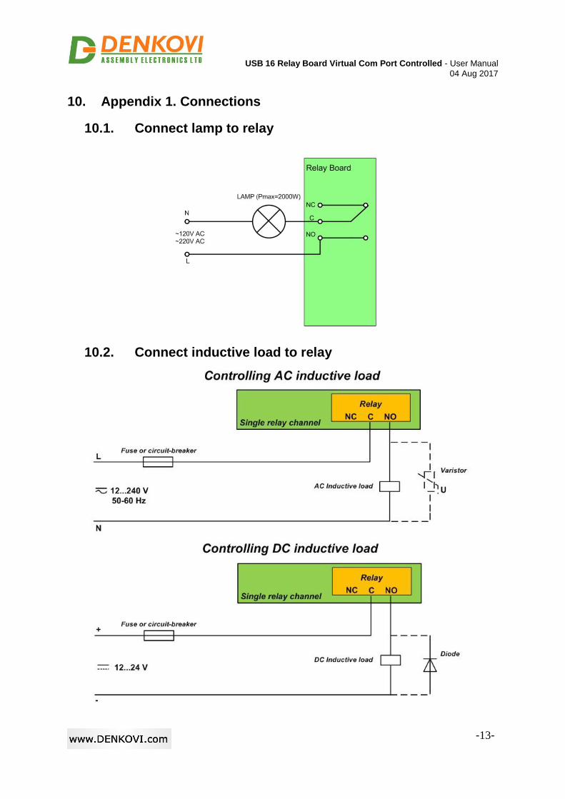
10. Appendix 1. Connections
10.1. Connect lamp to relay
10.2. Connect inductive load to relay
USB 16 Relay Board Virtual Com Port Controlled - User Manual
04 Aug 2017
-14-
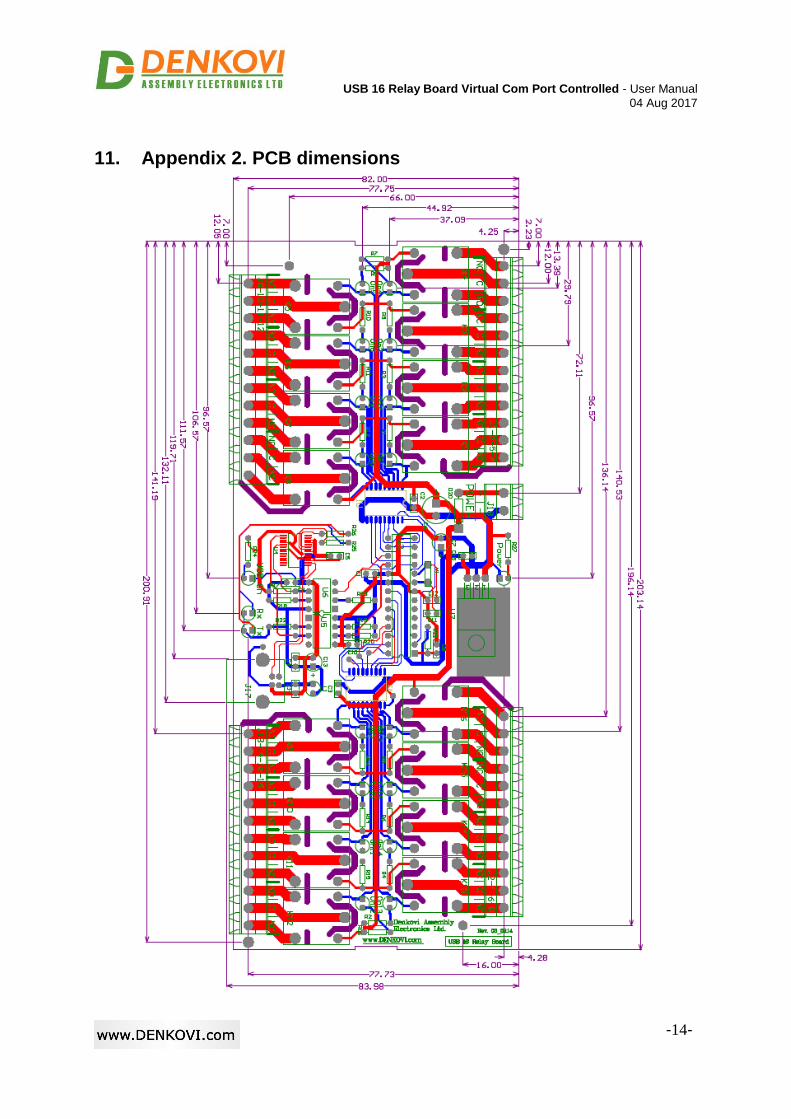
11. Appendix 2. PCB dimensions