Embed Size (px)
Citation preview
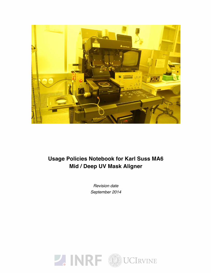
Usage Policies Notebook for Karl Suss MA6 Mid / Deep UV Mask Aligner
Revision date September 2014
2
Emergency Plan for Karl Suss MA6 Aligner Standard Operating Procedures for Emergencies
Contact information
Person Phone number
Lab Manager Jake Hes, 949-824-8239 (day), 562-522-8328 (alternate)
Director G.P. Li: 949-824-4194 (day), 949-824-2047 (alternate)
Staff
Super User
Mo Kebaili: 949-824-8239 (day), 949-494-5892 (alternate)
Carlos Ruiz (818) 527-6349 (Anytime, voicemail or text only)
Hazardous chemicals, gases, and conditions
Hazard name Description of hazard
High temperature Burn or ignition source
Electrical Hazards Electrical shock, ignition source
Lamp Explosion Mercury Vapors
Fingers could be jammed
DO NOT Take any action during Operation
Radiation Hazards High energy of UV light from exposure lamp
N2 (nitrogen) gas Asphyxiant
Alarms or indications of danger
Alarm type Condition and response
Alarm on console Problem with the process state. Halt the process, correct the problem or notify the staff or the lab manager before continuing.
Pungent or foul smell Not applicable
Emergency shutdown plan #1 In the event of an emergency, when there is very little time, press the large red emergency shut-off button at the front of the Tool. This action will shutdown the system, and will stop and turn off the exposure lamp. Leave the facility at once, and contact the lab manager or the staff.
3
Authorized users for Karl Suss MA6 Mask Aligner The following users have been authorized to use this equipment.
Staff user Date staff Initials
4
Usage Policies for Karl Suss MA6 Mask Aligner Standard policies for usage
The Karl Suss Mask Aligner performs high resolution photolithography. It offers unsurpassed flexibility in the handling of irregularly shaped substrates of differing thickness, as well as standard size wafers up to 6’’ in diameter. It uses 5”masks System and it can be operated manually. All contact exposure programs (vacuum, hard, soft contact and proximity) are provided to print structures far into the submicron region.
X- and Y- shift are below 0.1um and are not detectable by optical means. Wafers and substrates up to 6 mm thick may be processed.
The system is equipped with a Hg-Xe vapor lamp. The MA6 has upgraded optics designed to output in the mid-UV (250nm) range. The lamp is controlled by a CIC 100 constant intensity controller capable of delivering user-selectable UV doses which remain stable during the life of the lamp. Optical sensors monitor the UV output dose and provide feedback to the controller. There are 2 selectable channels. Both channels operate the lamp near its “idle power” (475W) to maximize lamp life. Because the lamp operates in constant intensity mode, the actual power will vary over time as the lamp ages. DO NOT change the power/settings on either channel – damage to the Hg-Xe lamp may result.
While the MA6 is designed for 250nm operation, the lamp and optics also provide higher wavelength illumination. Channel 1 regulates exposure dose by measuring the output at 250 nm, while Channel 2 measures at 320nm. The settings for each channel are as follows:
• Channel 1 (Cl1):
Sensor wavelength=365nm
Optical output power= 5mW
Nominal lamp power= 275W
• Channel 2 (Cl2):
Sensor wavelength= 405nm
Optical output power= 10mW
Nominal lamp power= 275W
Contact information The INRF staff or the lab manager can be reached at 824-8239 or 824-9831.
Authorized users Only INRF registered users who have completed the training and passed the certification may use this equipment. Users may only use the portion of the system for which they have been trained.
Training Users must have received direct training from the staff in order to use this equipment. Training is different from other aligners. Users are expected to understand the nature of the system, as well as the proper control. Training varies slightly, depending on the process to be performed for front side and back side alignment. Contact the staff for details and to arrange for a training session.
5
Usage logs Users are required to log all activities in the log sheets provided. All users must log in when they used the aligner (name date and time, type of substrate and size) on completion of their process in the user log sheets. If users notice anything unusual, they should note it in the user log sheets, and add details in the maintenance log sheets. Any maintenance to the tool must be logged in the maintenance log sheets (maintenance staff only).
Safety equipment There is no specific safety equipment for use on this tool, however cleanroom gloves and tweezers should be used when handling and placing substrates on the chuck, care should be taken.
Standard equipment and materials The laboratory provides the following: N2 blow off gun and isopropanol solvent.
User maintenance Users are requested to clean and wipe off the chuck after use. Spray the isopropanol into a lint-free cloth and wipe the chuck clean. Dispose of the cloth in a waste container marked for flammable solid waste.
Waste disposal Dispose of alcohol soaked wipes in a waste container marked for flammable solid waste.
Scheduling Reservation can be done on-line also the system can be used on a first-come, first served usage if no reservation was made.
Other issues Users should remain physically present in the cleanroom facility during the entire use of the aligner.
Users should not modify any standard recipe in the software. New recipes can be created, but once created, they should stay unedited. A modified recipe should be given a new name. This allows us to track down the history of a problem later, if necessary.
At no time should a user adjust a pressure regulator on a gas line. Gas control should be “on” or “off” only, using only the valves appropriately. For most gases, this is usually the valve at the cylinder head.
Non-standard use Users may not modify any hardware on this equipment. For use of non-standard processes, gases or materials, contact the staff or lab manager.
6
The intensities calibrated are i!line (365nm). Channel 2 is set to output 10.0 mW/cm2 for 365 nm. Please check the logbook or website for most recent calibration.
• Make sure you change gloves before using the mask aligner if you have been using
solvents or acids. The chuck holders and mask holders are expensive and can be
damaged by solvent or acid residue.
• There is a mercury lamp in the equipment. If the lamp explodes, immediately leave the
area, notify others in the lab to leave, and call the lab manager. If the lab manager is
not available, call EH & S for possible mercury spill clean!up.
• Occasionally, the video monitor begins flashing and cannot be adjusted to stop. If this
• happens, take out samples, do a “change mask” procedure to remove the mask, and turn the main power to the mask aligner off and back on. This usually fixes the problem.
• Calculate the exposure time by dividing the desired exposure dosage, which should be in mJ/cm2 by the through mask UV intensity measured in mW/cm2
Pre-Operation: 1. You must have clean set of gloves. 2. Log in to the PC and sign in the logbook.
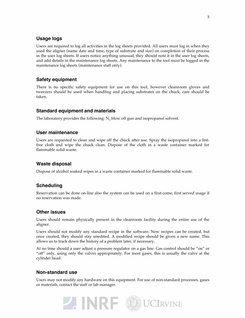
3. Power on Procedure: Shortly turn the POWER SWITCH ELECTRONIC on front panel control clockwise into ON position and release it. An example for the display message is
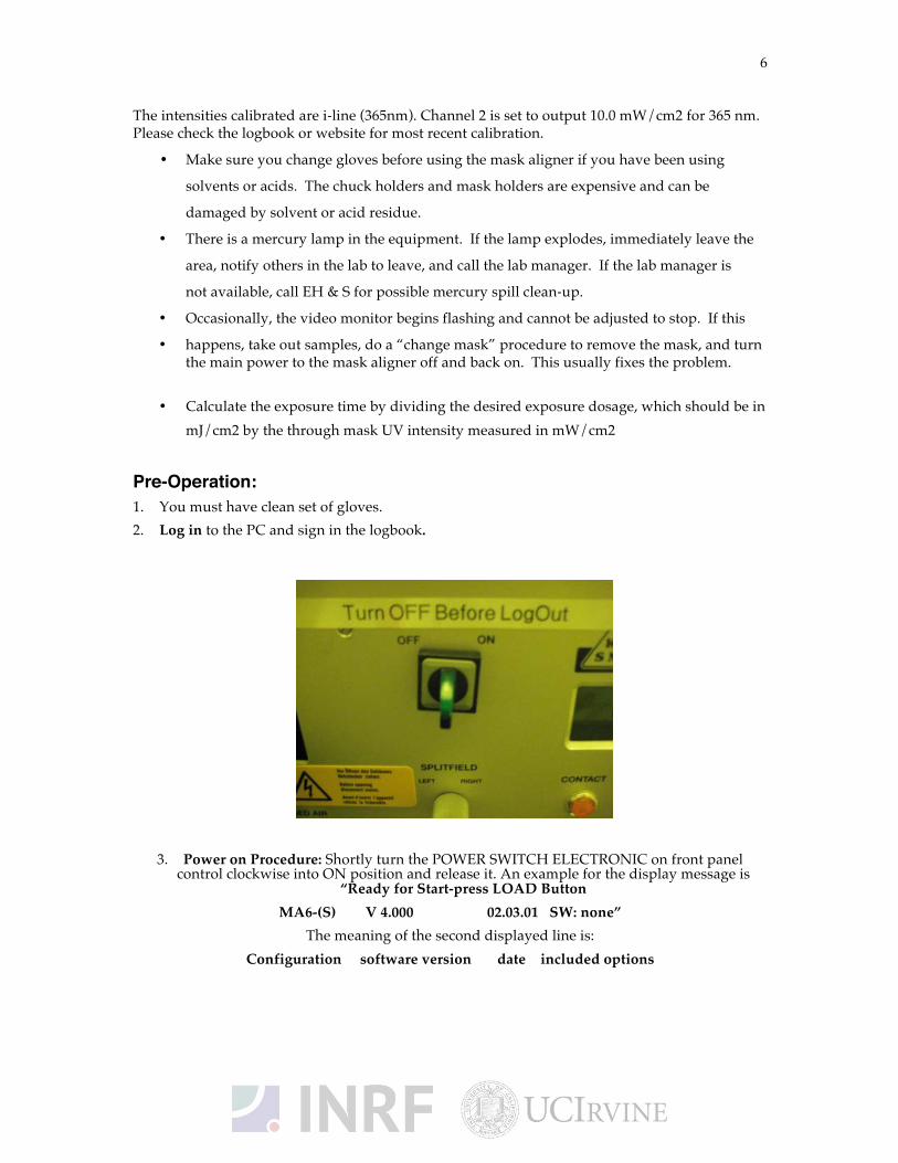
“Ready for Start-press LOAD Button MA6-(S) V 4.000 02.03.01 SW: none”
The meaning of the second displayed line is: Configuration software version date included options
7
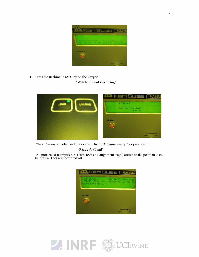
4. Press the flashing LOAD key on the keypad. “Watch out tool is starting!”
The software is loaded and the tool is in its initial state, ready for operation: “Ready for Load” All motorized manipulators (TSA, BSA and alignment stage) are set to the position used
before the Tool was powered off.
8
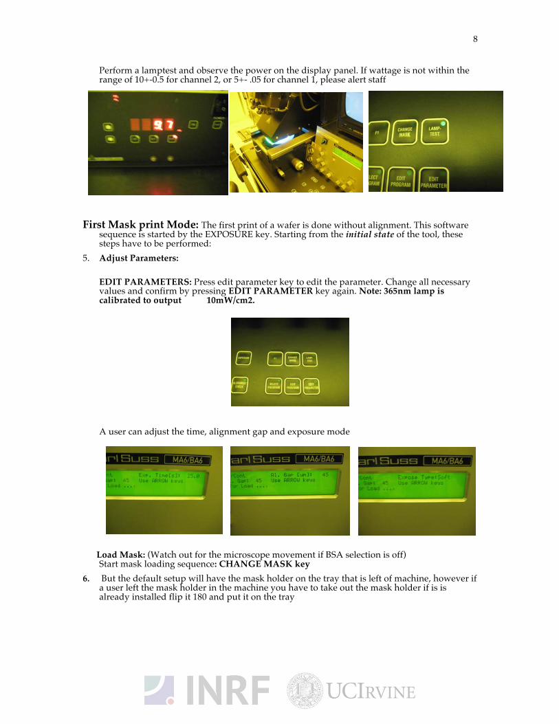
Perform a lamptest and observe the power on the display panel. If wattage is not within the range of 10+-0.5 for channel 2, or 5+- .05 for channel 1, please alert staff
First Mask print Mode: The first print of a wafer is done without alignment. This software
sequence is started by the EXPOSURE key. Starting from the initial state of the tool, these steps have to be performed:
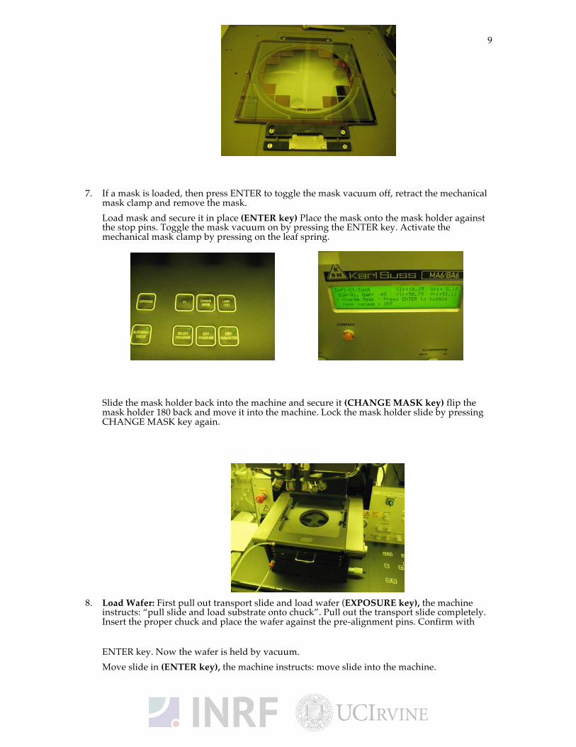
5. Adjust Parameters: EDIT PARAMETERS: Press edit parameter key to edit the parameter. Change all necessary values and confirm by pressing EDIT PARAMETER key again. Note: 365nm lamp is calibrated to output 10mW/cm2.
A user can adjust the time, alignment gap and exposure mode
Load Mask: (Watch out for the microscope movement if BSA selection is off)
Start mask loading sequence: CHANGE MASK key 6. But the default setup will have the mask holder on the tray that is left of machine, however if
a user left the mask holder in the machine you have to take out the mask holder if is is already installed flip it 180 and put it on the tray
9
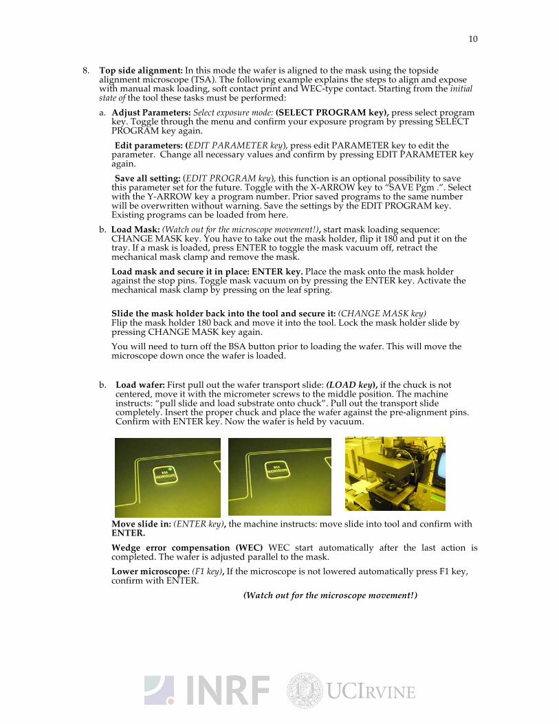
7. If a mask is loaded, then press ENTER to toggle the mask vacuum off, retract the mechanical mask clamp and remove the mask. Load mask and secure it in place (ENTER key) Place the mask onto the mask holder against the stop pins. Toggle the mask vacuum on by pressing the ENTER key. Activate the mechanical mask clamp by pressing on the leaf spring. Slide the mask holder back into the machine and secure it (CHANGE MASK key) flip the mask holder 180 back and move it into the machine. Lock the mask holder slide by pressing CHANGE MASK key again.
8. Load Wafer: First pull out transport slide and load wafer (EXPOSURE key), the machine instructs: “pull slide and load substrate onto chuck”. Pull out the transport slide completely. Insert the proper chuck and place the wafer against the pre-alignment pins. Confirm with ENTER key. Now the wafer is held by vacuum. Move slide in (ENTER key), the machine instructs: move slide into the machine.
10
8. Top side alignment: In this mode the wafer is aligned to the mask using the topside alignment microscope (TSA). The following example explains the steps to align and expose with manual mask loading, soft contact print and WEC-type contact. Starting from the initial state of the tool these tasks must be performed: a. Adjust Parameters: Select exposure mode: (SELECT PROGRAM key), press select program
key. Toggle through the menu and confirm your exposure program by pressing SELECT PROGRAM key again.
Edit parameters: (EDIT PARAMETER key), press edit PARAMETER key to edit the parameter. Change all necessary values and confirm by pressing EDIT PARAMETER key again.
Save all setting: (EDIT PROGRAM key), this function is an optional possibility to save this parameter set for the future. Toggle with the X-ARROW key to “SAVE Pgm .”. Select with the Y-ARROW key a program number. Prior saved programs to the same number will be overwritten without warning. Save the settings by the EDIT PROGRAM key. Existing programs can be loaded from here.
b. Load Mask: (Watch out for the microscope movement!), start mask loading sequence: CHANGE MASK key. You have to take out the mask holder, flip it 180 and put it on the tray. If a mask is loaded, press ENTER to toggle the mask vacuum off, retract the mechanical mask clamp and remove the mask.
Load mask and secure it in place: ENTER key. Place the mask onto the mask holder against the stop pins. Toggle mask vacuum on by pressing the ENTER key. Activate the mechanical mask clamp by pressing on the leaf spring.
Slide the mask holder back into the tool and secure it: (CHANGE MASK key) Flip the mask holder 180 back and move it into the tool. Lock the mask holder slide by pressing CHANGE MASK key again.
You will need to turn off the BSA button prior to loading the wafer. This will move the microscope down once the wafer is loaded.
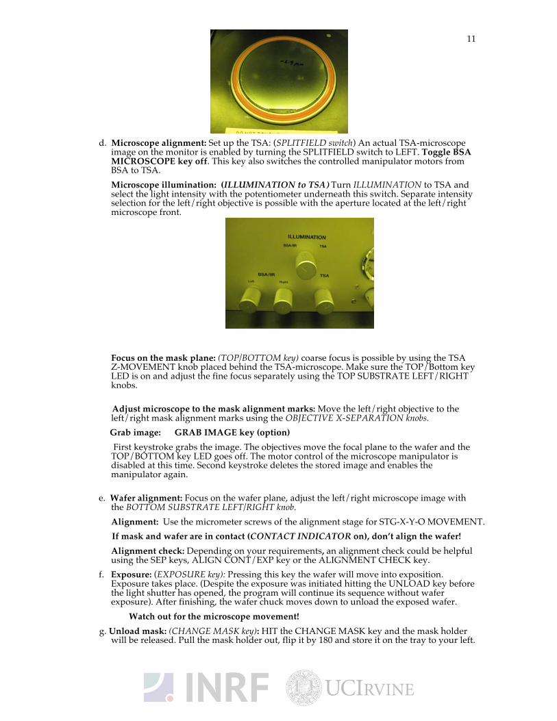
b. Load wafer: First pull out the wafer transport slide: (LOAD key), if the chuck is not
centered, move it with the micrometer screws to the middle position. The machine instructs: “pull slide and load substrate onto chuck”. Pull out the transport slide completely. Insert the proper chuck and place the wafer against the pre-alignment pins. Confirm with ENTER key. Now the wafer is held by vacuum.
Move slide !": (ENTER key), the machine instructs: move slide into tool and confirm with ENTER. Wedge error compensation (WEC) WEC start automatically after the last action is completed. The wafer is adjusted parallel to the mask. Lower microscope: (F1 key), If the microscope is not lowered automatically press F1 key, confirm with ENTER.
(Watch out for the microscope movement!)
11
d. Microscope alignment: Set up the TSA: (SPLITFIELD switch) An actual TSA-microscope
image on the monitor is enabled by turning the SPLITFIELD switch to LEFT. Toggle BSA MICROSCOPE key off. This key also switches the controlled manipulator motors from BSA to TSA.
Microscope illumination: (ILLUMINATION to TSA) Turn ILLUMINATION to TSA and select the light intensity with the potentiometer underneath this switch. Separate intensity selection for the left/right objective is possible with the aperture located at the left/right microscope front.
Focus on the mask plane: (TOP/BOTTOM key) coarse focus is possible by using the TSA
Z-MOVEMENT knob placed behind the TSA-microscope. Make sure the TOP/Bottom key LED is on and adjust the fine focus separately using the TOP SUBSTRATE LEFT/RIGHT knobs.
Adjust microscope to the mask alignment marks: Move the left/right objective to the left/right mask alignment marks using the OBJECTIVE X-SEPARATION knobs.
Grab image: GRAB IMAGE key (option) First keystroke grabs the image. The objectives move the focal plane to the wafer and the TOP/BOTTOM key LED goes off. The motor control of the microscope manipulator is disabled at this time. Second keystroke deletes the stored image and enables the manipulator again.
e. Wafer alignment: Focus on the wafer plane, adjust the left/right microscope image with the BOTTOM SUBSTRATE LEFT/RIGHT knob. Alignment: Use the micrometer screws of the alignment stage for STG-X-Y-O MOVEMENT.
If mask and wafer are in contact (CONTACT INDICATOR on), don’t align the wafer! Alignment check: Depending on your requirements, an alignment check could be helpful
using the SEP keys, ALIGN CONT/EXP key or the ALIGNMENT CHECK key. f. Exposure: (EXPOSURE key): Pressing this key the wafer will move into exposition.
Exposure takes place. (Despite the exposure was initiated hitting the UNLOAD key before the light shutter has opened, the program will continue its sequence without wafer exposure). After finishing, the wafer chuck moves down to unload the exposed wafer.
Watch out for the microscope movement! g. Unload mask: (CHANGE MASK key): HIT the CHANGE MASK key and the mask holder
will be released. Pull the mask holder out, flip it by 180 and store it on the tray to your left.
12
Hit ENTER to switch the mask vacuum off. Retract the mechanical clamping and remove the mask.
h. Turn tool Power Off: Toggle POWER SWITCH to OFF position.
9. Bottom side alignment: The wafer is aligned to the mask using the bottom side alignment microscope (BSA). The following example explains the steps to align and expose with manual mask loading, vacuum contact and WEC-type proximity. Starting the initial state of the machine these steps have to be performed: a. Adjust Parameters: Select exposure mode:(SELECT PROGRAM key), press SELECT
PROGRAM key. Toggle through the menu and confirm your exposure program by pressing SLELECT PROGRAM key again. Edit parameters: EDIT PARAMETER key. This function is an optional possibility to save this parameter set for the future. Toggle with the X-ARROW keys to “SAVE Pgm.”. Select with the Y-ARROW keys a program number. Prior saved programs to the same number will be overwritten without warning. Save the setting by pressing the EDIT PROGRAM key. Existing programs can be loaded from here.
b. Load Mask: (Watch out for the microscope movement!), start mask loading sequence: (CHANGE MASK key), you have to take out the mask holder, flip it 180 and put it on the tray. If a mask is loaded, press ENTER to toggle the mask vacuum off, retract the mechanical mask clamp and remove the mask.
Load mask and secure it in place: (ENTER key), place the mask onto the mask holder against the stop pins. Toggle mask vacuum on by pressing the ENTER key. Activate the mechanical mask clamp by pressing on the leaf spring.
Slide the mask holder back into the tool and secure it: (CHANGE MASK key), flip the mask holder 180 back and move it into the tool. Lock the mask holder slide by pressing CHANGE MASK key again. You will need to turn on the BSA button prior to loading the wafer. This will prevent the topside microscope from coming down after loading the wafer
c. Load wafer chuck for BSA: If the chuck is not centered, move it with the micrometer screws to the middle position. Insert a proper chuck without wafer onto the transport slide. Move the BSA-chuck (placed onto the transport slide) into the machine. Don’t press a key.
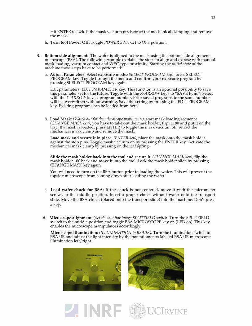
d. Microscope alignment: (Set the monitor image SPLITFIELD switch) Turn the SPLITFIELD
switch to the middle position and toggle BSA MICROSCOPE key on (LED on). This key enables the microscope manipulators accordingly.
Microscope illumination: (ILLUMINATION to BSA/IR). Turn the illumination switch to BSA/IR and adjust the light intensity by the potentiometers labeled BSA/IR microscope illumination left/right.
13
Focus on the top focal plane: (TOP/BOTTOM key) Make sure the TOP/BOTTOM key LED is on and adjust the fine focus separately with the TOPS SUBSTRATE LEFT/RIGHT knobs.
Move objectives to the chuck opening: (left, BOTH, RIGHT keys) Select one of these keys to move the left/right objective with the ARROW keys. If necessary use the fast speed mode (FAST key LED on).
Grab image: (GRAB IMAGE key option) First keystroke grabs the mask image. The objectives move to the wafer focus plane TOP/BOTTOM key LED off. The motor control of the microscope manipulator is disabled. Second keystroke GRAB IMAGE key deletes stored image and enables the manipulator again.
e. Load wafer: Pull out transport slide and load wafer: (LOAD key), we recommend to use a transparent wafer chuck. Move the loaded transport slide in and confirm with ENTER key.
Wedge error compensation: (WEC), WEC starts automatically. The substrate moves to the alignment gap.
f. Substrate alignment: Adjust the microscope illumination using the BSA/IR microscope illumination left/right. Select the Substrate focus plane by deactivating the TOP/BOTTOM key. Focus with BOTTOM SUBSTRATE LEFT/RIGHT focus knob. Search for a reference wafer alignment mark with the BSA microscope. Store this stage position by activating the SET REFERENCE key. Search for a second wafer alignment mark only by the x-movement of the BSA-microscope. Toggle back to the reference alignment mark using the SCAN key. Press GRAB IMAGE key to store the reference alignment mark image. Toggle to the second alignment mark using the SCAN key.
Substrate alignment: Adjust the live substrate alignment mark to the stored one only with the movement of the alignment stage about ! of the misalignment. Switch the manipulator control to BSA deactivating the STG/TSA/BSA button. Press SCAN key to toggle to the reference position. Press GRAB IMAGE key to release the stored image. Deactivate the TOP/BOTTOM key and grab the new image using GRAB IMAGE key. Repeat this substrate alignment until there is not misalignment left.
Substrate to mask alignment: Move the substrate away using the x-y-movement of the alignment stage to see the real mask alignment mark. Focus on the mask plane by activating the TOP/BOTTOM key and using the corresponding TOP SUBSTRATE left/right focus knob. Press GRAB IMAGE key to store the mask alignment mark. Move the substrate back using the x-y-movement of the alignment stage. Focus on the substrate plane by deactivating the TOP/BOTTOM key and using the corresponding TOP SUBSTRATE LEFT/RIGHT focus knob. Align the substrate alignment mark to the mask alignment mark. Check the alignment using the ALIGN CONT/EXP key.
g. Exposure: (EXPOSURE key): By pressing this key the substrate will move into exposure
position, and the exposure takes place. Despite the exposure was initiated, hitting the UNLOAD key before the light shutter has opened will continue its exposure program sequence without substrate exposure. After finishing the wafer chuck moves down to unload the exposed substrate.
h. Unload mask: (CHANGE MASK key): Hit the CHANGE MASK key and the mask holder will be released. Pull the mask holder out, flip it by 180 and store it on the tray to your left. Hit ENTER to switch the mask vacuum off. Retract the mechanical clamping and remove the mask.
i. Make sure system is set back to BSA: Hit the BSA button until a green light illuminates. This will avoid the microscope movement during ever load.
j. Turn Tool off: (Toggle POWER SWITCH ELECTRONIC to position OFF).
12. Return to original state
a. Unload mask: (CHANGE MASK key): Hit the CHANGE MASK key and the mask holder will be released. Pull the mask holder out, flip it by 180 and store it on the tray to your left.
14
Hit ENTER to switch the mask vacuum off. Retract the mechanical clamping and remove the mask.
b. Make sure system is set back to BSA: Hit the BSA button until a green light illuminates. This will avoid the microscope movement during ever load.
c. Turn Tool off: (Toggle POWER SWITCH ELECTRONIC to position OFF).
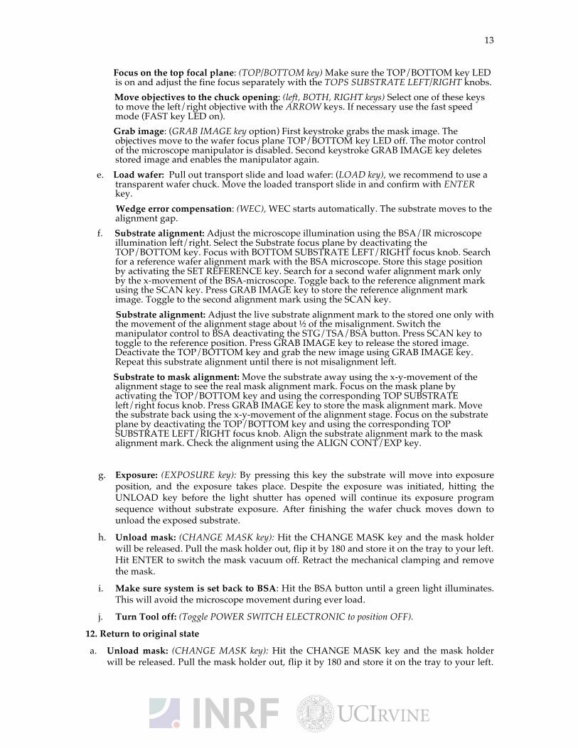
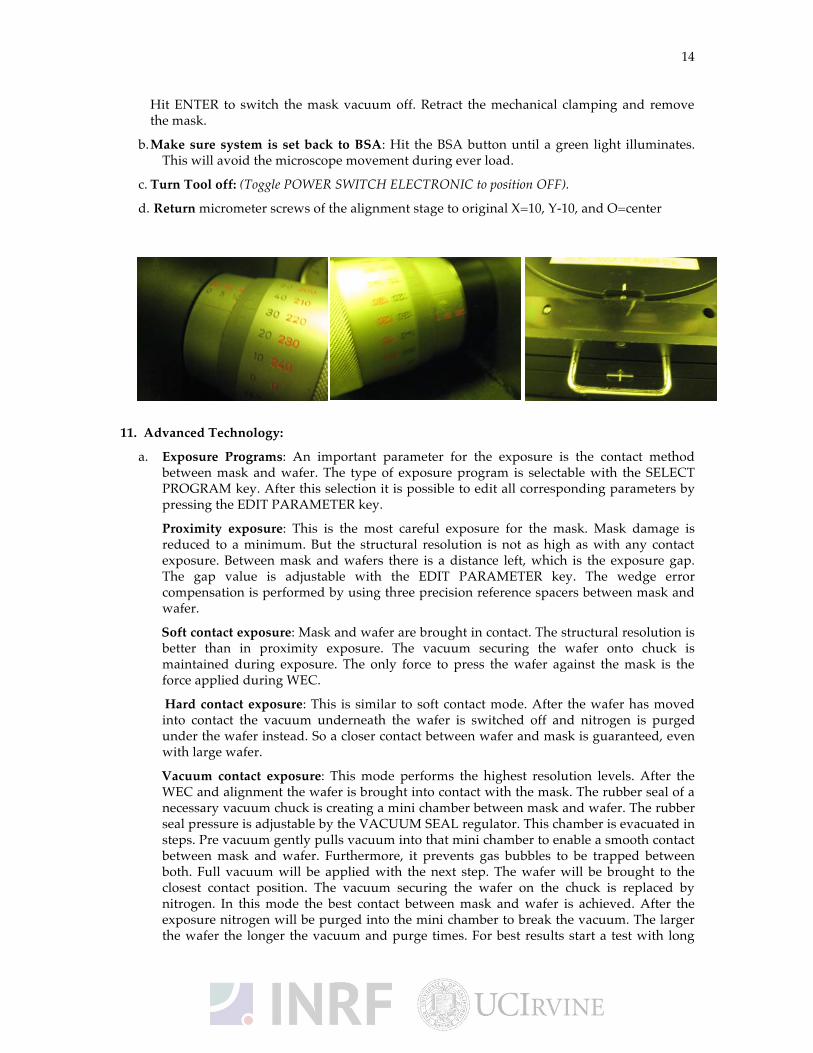
d. Return micrometer screws of the alignment stage to original X=10, Y-10, and O=center
11. Advanced Technology:
a. Exposure Programs: An important parameter for the exposure is the contact method between mask and wafer. The type of exposure program is selectable with the SELECT PROGRAM key. After this selection it is possible to edit all corresponding parameters by pressing the EDIT PARAMETER key.
Proximity exposure: This is the most careful exposure for the mask. Mask damage is reduced to a minimum. But the structural resolution is not as high as with any contact exposure. Between mask and wafers there is a distance left, which is the exposure gap. The gap value is adjustable with the EDIT PARAMETER key. The wedge error compensation is performed by using three precision reference spacers between mask and wafer.
Soft contact exposure: Mask and wafer are brought in contact. The structural resolution is better than in proximity exposure. The vacuum securing the wafer onto chuck is maintained during exposure. The only force to press the wafer against the mask is the force applied during WEC.
Hard contact exposure: This is similar to soft contact mode. After the wafer has moved into contact the vacuum underneath the wafer is switched off and nitrogen is purged under the wafer instead. So a closer contact between wafer and mask is guaranteed, even with large wafer.
Vacuum contact exposure: This mode performs the highest resolution levels. After the WEC and alignment the wafer is brought into contact with the mask. The rubber seal of a necessary vacuum chuck is creating a mini chamber between mask and wafer. The rubber seal pressure is adjustable by the VACUUM SEAL regulator. This chamber is evacuated in steps. Pre vacuum gently pulls vacuum into that mini chamber to enable a smooth contact between mask and wafer. Furthermore, it prevents gas bubbles to be trapped between both. Full vacuum will be applied with the next step. The wafer will be brought to the closest contact position. The vacuum securing the wafer on the chuck is replaced by nitrogen. In this mode the best contact between mask and wafer is achieved. After the exposure nitrogen will be purged into the mini chamber to break the vacuum. The larger the wafer the longer the vacuum and purge times. For best results start a test with long
15
times and reduce them gradually. All the parameters can be set using the using the EDIT PARAMETER key.
Low vacuum contact exposure: (This mode is similar to vacuum contact with one difference) the vacuum level in the wafer chamber can be adjusted by the LOW VACUUM ADJUSTMENT regulator. So the high resolution level of the vacuum contact exposure can be combined with a minimum mechanical stress for wafer and mask. Set an appropriate vacuum with the vacuum chamber regulator and test the result using the ALIGNMRNT CHECK key.
Flood exposure: It is possible to expose the whole wafer without a mask. After this mode is selected, the exposure can be started from the initial state by pressing the EXPOSURE key. The exposure takes place as long as the exposure time was set independent if a mask (and mask holder) is loaded or not.
Multiple exposures: For special applications the numerical value for the overall exposure time can be segmented into equal exposure intervals alternating with time intervals in which the wafer is not exposed. One exposure time and one wait time is named as one exposure cycle.
To perform Multiple Exposures, proceed as follows:
• Select the corresponding exposure program by the SELECT PROGRAM key.
• Press the MULTIPLE EXPOSURES key.
• Press the EDIT PARAMETER key.
• Edit the parameter for the exposure program. Edit the numerical value of the corresponding parameters wait time and cycles.
• Press the flashing EDIT PARAMETER key to finish editing and start alignment followed by the multiple exposure process.
Wedge error compensation: (WEC): During this procedure the topside of the wafer will be set exactly parallel to the bottom side of the mask. This guarantees a perfect gap setting and so a homogeneous quality of the exposed structures over the whole wafer. Set the WEC type using the EDIT PARAMETER key. Two methods are standard:
Contact mode: For the exact parallel setting the wafer will be moved against the mask.
Spacer mode: To treat the mask and the wafer with maximum care the machine moves spacers in between both. Proximity mask holder is necessary. Contact area is reduced to three points near the wafer edge.