Embed Size (px)
Citation preview

Signaling cassette KSR-32
Type: KSR-32-M-XXX-XXX
Usage instruction (version 2.07)
Copyright 2010 - 2016 by PUP Kared. All rights reserved.

Usage instruction - KSR-32
PUP KARED Sp. z o.o. reserves all rights to make any changes in its products, because of continuous development and improvement of products technical characteristic. Such changes cannot be always included in the technical documentation.Brands and product names mentioned in this instruction are trademarks or registered trademarks of their respective owners.
Contact data:
PUP KARED Sp. z o.oul. Kwiatowa 3/180-180 Gdańsk – KowaleTelephone 048-58-322-82-31, 048-58-324-86-45Mobile phone 048-602-152-740Fax 048-58-322-82-33, 048-58-324-86-46E mail: [email protected] http://www.kared.com.pl/
IMPORTANCE OF THE USAGE INSTRUCTION
In case of any doubts regarding interpretation of this usage instruction, please contact directly with the manufacturer.We look forward to hear from our users about any suggestions, opinions and critical remarks. All suggestions and opinions can be submitted by telephone or in written form. This will help us to make this instruction more friendly for our users, including their request and requirements.
The device, to which this instruction is attached contains impossible to remove potential threats for peoples and material properties. Therefore, each person who operates this device or performs any activities connected with operation and maintenance of this device must be properly trained and familiar with potential threats generated by this device. Each user of this device must carefully read, understand and observe all usage instruction, especially guidelines regarding safety.
Copyright 2010 - 2016 by PUP Kared. All rights reserved.This usage instruction can be reproduced and distributed only in its entirety.
PUP KARED Sp. z o.o. IU-KSR-32-M_v.2.07 Page 2/44

Usage instruction - KSR-32
Table of contents:IMPORTANCE OF THE USAGE INSTRUCTION................................................................................2
INFORMATION ABOUT CONFORMITY.............................................................................................4
1. Applicability of the device................................................................................................................5
2. Safety rules.....................................................................................................................................5
3. Technical description.......................................................................................................................73.1. General description.................................................................................................................................. 73.2. Enclosure................................................................................................................................................. 73.3. Operation description............................................................................................................................... 83.4. Operation modes of the device................................................................................................................83.5. Communication........................................................................................................................................ 93.6. Alarm states signalization........................................................................................................................ 93.7. Operating the alarm states....................................................................................................................143.8. Special functions for TEST, KAA and KAO buttons................................................................................143.9. Events registration................................................................................................................................. 153.10. WatchDog function............................................................................................................................... 15
4. Technical data...............................................................................................................................15
5. Information about completeness...................................................................................................16
6. Starting-up....................................................................................................................................176.1. Assembly of the device.......................................................................................................................... 176.2. Connecting power supply and inputs.....................................................................................................176.3. Connecting RS485 network...................................................................................................................196.4. Connecting devices for synchronous operation.....................................................................................226.5. Programming......................................................................................................................................... 226.5.1. Available registers............................................................................................................................... 226.5.2. Description of the registers................................................................................................................. 306.5.3. Programming example........................................................................................................................376.5.4. Setting the time for the internal timer – service mode.........................................................................396.5.5. Setting the time for the internal timer – broadcast..............................................................................396.5.6. Writing and reading of the inputs channel names...............................................................................396.5.7. Forcing service mode activation.........................................................................................................406.5.8. Address request.................................................................................................................................. 41
7. Usage........................................................................................................................................... 41
8. Storage......................................................................................................................................... 43
9. Utilization...................................................................................................................................... 43
10. Warranty and service..................................................................................................................44
11. Ordering method.........................................................................................................................44
PUP KARED Sp. z o.o. IU-KSR-32-M_v.2.07 Page 3/44

Usage instruction - KSR-32
INFORMATION ABOUT CONFORMITY
The device described in this instruction is designed for use in industrial environment. During construction and production of this device were used norms that provide realization of safety rules and measures provided that, all instructions described below regarding installation, start-up and usage of this device will be observed by the user.
This device is Class A device. In residential buildings it can generate radio-electrical interferences. In such cases, the user of this device can be requested to apply proper remedial measures and actions.
This device is in conformity with the following EU directives: • LVD 2006/95/WE - LVD - directive of the European Parliament and of the Council of December
12, 2006, on the harmonization of the laws of Member States relating to electrical equipment designed for use within certain voltage limits - applied on the territory of the Republic of Poland by the Ordinance of the Minister of Economy of August 21, 2007 regarding essential requirements for electric equipment (Journal of Laws, No. 155, item 1089)
• EMC 2004/108/WE - EMC - directive of the European Parliament and of the Council of December 15, 2004, on the harmonization of the laws of Member States relating to electromagnetic compatibility – applied on the territory of the Republic of Poland by the Act of April 13, 2007 about electromagnetic compatibility (Journal of Laws, No. 82, item 556).
Harmonized norm with Directive LVD 2006/95/WE
PN-EN 60255-5:2005 - Power-electric transmitters – Part 5: Coordination of measuring transmitters and protecting devices insulation – Requirements and examinations.
Harmonized norm with Directive EMC 2004/108/WE
PN-EN 50263:2003(U) - Electromagnetic compatibility (EMC). Norm regarding measuring transmitters and protective devices.
PUP KARED Sp. z o.o. IU-KSR-32-M_v.2.07 Page 4/44

Usage instruction - KSR-32
1. Applicability of the device
Signaling cassette KSR-32 is designed to provide visual and sound control of 32 limit states in supervised facilities. It informs operating personnel that the set-points of limit values of a variety of parameters – such as pressure, temperature, flow, time limit, etc. – have been exceeded during the technological process. The state of controlled devices is presented in the form of fields with captions, highlighted with constant or pulsating color light (green, red, yellow). The KSR-32 signaling cassettes have a modular structure and allow to build signaling boards with the number of inputs being a multiple of 32. It is possible to use any number of KS-P button modules.
2. Safety rules
Information provided in this chapter are meant for familiarizing the user with proper installation and operation of the product. It is assumed, that personnel responsible for installation, start-up and usage of this device has proper qualifications and is aware of potential threats connected with handling and operating electric equipment.This device conforms all requirements regarding safety rules and standards. During designing stage of this device, a special attention was paid to user safety.Installation of the deviceThis device should be installed in place that provides proper environmental conditions described in the technical data. The device should be firmly mounted and protected against any mechanical damages and also against accidental access of non-authorized personnel. All cross-section ans connection types of wiring should be conformable with guidelines described in this instruction.Start-up of the deviceDuring start-up of the device, it is important to check informations provided on the rating plate and the following conditions:• continuity of the earthing cables (if required),• conformity of the measuring values (voltage, current),• whether the permissible value of relay outputs is not exceeded,• conformity of voltage values for two-states inputs,•
Insulation test can cause load of dispersed capacities to the dangerous voltage value. After finishing each test, such capacities should be discharged.
After applying supply voltage, the proper settings should made.
Usage of the device
This device should operate in the conditions described in the technical data.All persons who operate this device should be authorized and familiarized with usage instruction.
PUP KARED Sp. z o.o. IU-KSR-32-M_v.2.07 Page 5/44

Usage instruction - KSR-32
Removing the enclosure
Before starting any works that require removal of the enclosure, all measuring and auxiliary voltages should be completely disconnected. Dangerous voltages can be active on the parts the device for the period of about 1 minute from the disconnection time.
All integrated circuits used in this device are very sensitive to electrostatic discharges, and therefore opening of the device without proper anti-electrostatic equipment can cause damage to the device.UsageAfter installation this device does not require any additional service, except periodical inspections required by the applicable regulations. In case of any failures, please contact with the manufacturer. Manufacturer of this device is responsible for any services regarding start-up and any warranty/after warranty services. All warranty conditions are provided on the warranty card.Modifications and changesBecause of safety precautions, all modifications and changes regarding functionality of the device described in this instruction are prohibited. Any modification of the device performed without written consent of the manufacturer will cause loss of right to any contractual and tort liability claims against PUP Kared Spółka z o.o.Replacement of parts and sub-assemblies included in this device and usage of parts originated from third parties can disturb safety of the device users and can cause improper operation of the device.PUP KARED Sp. z o.o. should not be liable for any damages caused by application of improper parts and sub-assemblies.AbnormalitiesThe competent person should be informed about any abnormalities in functioning of the device and other damages and failures. All repairs should be performed only by authorized professionals with proper qualifications.Rating plates, information plates and stickersAll advices provided in the form of descriptions placed on the device and on the information plates and stickers should be absolutely observed. All damaged or illegible plates and stickers should immediately replaced for new ones.Threats impossible to elimination
During normal usage of the device, the user should not touch terminals, because of active voltages with values very dangerous for people.
PUP KARED Sp. z o.o. IU-KSR-32-M_v.2.07 Page 6/44

Usage instruction - KSR-32
3. Technical description
3.1. General description
Signaling cassette KSR-32 is designed to provide visual and sound control of 32 limit states in supervised facilities. Reaction manner for excitation with alarming state is defined by the user. The device is equipped with 2 communication connections RS485 with Modbus-RTU and IEC 60870-5-103 protocols. One connection is used for communication with master systems and provides readings of the actual alarming input state, signaling state and registered events. In digital input writing state it provides alteration of luminous fields state with using commands send from the master system. Second connection provides connection of second, "slave" cassette that reproduces signaling state of the "master" cassette or usage of the binary inputs concentrator instead of embedded inputs. Embedded or external buttons provide reception and cancellation of alarming signalization, and also test of LED diodes illumination correctness. The device can be equipped with a relay with WatchDog function which determines correct operation.The device is supplied with 24 V ± 10% DC voltage. It is possible to equip the device with a power supply adapted to work with a voltage of a different value. Communication ports, input terminals and relay outputs are galvanically insulated.
3.2. Enclosure
Enclosure of signaling cassette KSR-32 is shown on Figure 3.1.
Optional button module is shown on Figure 3.2.
PUP KARED Sp. z o.o. IU-KSR-32-M_v.2.07 Page 7/44
Fig. 3.1. Enclosure dimensions
Fig. 3.2. Button module dimensions

Usage instruction - KSR-32
3.3. Operation description
Signaling cassette provides the following functions:– Cyclical (1 ms period – in standard mode) reading of the input states,– Input signals filtration with time constant set by the user,– Excitation response delay with set time,– Elongation of excitation duration time,– Events writing – appearance of the alarming state, disappearance of the alarming state and
alarm take-over by the operating personnel
The block diagram of the device is showed on Figure 3.2.
3.4. Operation modes of the device
The device can be operated in the mode selected by the user.– Standard mode – the device receives informations about alarm states with embedded binary
inputs (if the device is not equipped with the binary inputs module, this operation mode is not available),
– Concentrator operation mode – the device receives informations from the binary inputs concentrator using RS485 network,
– Signaling duplication mode – the device connected to RS485 network with master cassette duplicates the illumination diode fields of the master cassette,
– Signalization enforcing mode – the device connected using RS485 network with master device that digitally interchanges the input state (no response for signal alterations from binary inputs module).
PUP KARED Sp. z o.o. IU-KSR-32-M_v.2.07 Page 8/44
Fig. 3.2. Block diagram

Usage instruction - KSR-32
3.5. Communication
The signaling cassette can be operated in RS485 network – Modbus RTU protocol - as the „slave” type device. For this reason, the "RS485 to the system" connection is used. The master system using "Read Holding Registers (0x03)” command can download the actual binary inputs state of the device, LED diodes illumination state and recorded events.The second connection - "local" - can be used to connect the device to the binary inputs concentrator cassette (e.g. iKAR IO manufactured by Kared) or to the second cassette used for duplication of alarm signalization.
3.6. Alarm states signalization
The response manner for alarm state is optionally defined by the user for each channel. Alarming signalization cycle consists of 5 or 7 phases depending on whether the given channel is assigned to the alarm group, for which id signaled the alarm that appeared as the first. The user is responsible for defining the following phases depending on the operation mode:
1. Lack of distinguishing of the first alarm:— Normal operation,— Alarm appearance,— Alarm reception,— Alarm disappearance before reception,— Alarm disappearance after reception,
2. Distinguishing of the first alarm:— Normal operation,— Appearance of the first alarm,— Appearance of the consecutive alarms,— Alarm reception,— First alarm disappearance before reception,— Other alarms disappearance before reception,— Alarm disappearance after reception
The user can define for each phase:
1. Illumination manner:— Diode field disabled,— Field is illuminated with continuous light,— Field is pulsating slowly (1 Hz),— Field is pulsating quickly (2 Hz),
1. Light color:— Green,— Red,— Yellow.
1. Additional reactions:— Turning on the ring relay,— Turning on the light relay No. 1 (only after alarm reception),— Turning on the light relay No. 2 (only after alarms cancellation),
1. Alarm triggering manner:— Increasing slope,— Decreasing slope.
All alarm signalization phases are presented in Table 3.1.
PUP KARED Sp. z o.o. IU-KSR-32-M_v.2.07 Page 9/44

Usage instruction - KSR-32
Table 3.1 Phases of alarm signalization cycle
Phase number Phase description
1 Normal operation. Lack of actual alarms. Previous alarms were received and canceled.
2 Appearance of first alarm3 Appearance of consecutive alarms4 Reception of information about alarms by pressing KAO button5 Disappearance of received alarms6 Disappearance of first (distinguished) alarm7 Disappearance of non received consecutive alarms
Diagrams for transition between consecutive states are represented on Figures 3.3 and 3.4.
PUP KARED Sp. z o.o. IU-KSR-32-M_v.2.07 Page 10/44
Fig. 3.3. Diagrams for transition between phases (operation with distinguishing of first alarm)

Usage instruction - KSR-32
To facilitate programming activities for signaling cassettes, the manufacturer prepared proper tool and exampled alarm functions.
2-color basic function
1. In normal state (no excitation with alarm signal) the alarm signal field is illuminated with green color.
2. Change of the binary signal on the input, after filtration by control of the state with time t filtr, causes illumination of the field with signal description with pulsating color, and switching-on the alarm relay of the sound signal. For each track, there is the possibility to set delay time tON of the alarm signal and delay time tOFF for disappearance of the signal. Delay ranges can be set individually from 1 ms up to 60 000 ms.
3. By pressing KAA button (Acoustic Alarm Cancellation) the acoustic alarm can be canceled. The field on the board with actuated alarm channel still pulsates with flashing red light.
4. By pressing KAO button (Optical Alarm Cancellation) the illumination of the field changes from flashing to stable.
PUP KARED Sp. z o.o. IU-KSR-32-M_v.2.07 Page 11/44
Fig. 3.4. Diagrams for transition between phases (operation without distinguishing of first alarm)
Fig. 3.5. 2-color basic function

Usage instruction - KSR-32
5. Disappearance of the alarm reason causes the change of the illuminated field color from red to yellow, and after another pressing if the KAO button to green color.
6. Disappearance of the alarm reason before pressing KAO button causes change of the flashing color of the illuminated field from red to yellow, and after pressing KAO button, to green color.
1-color basic function
1. In normal state (no excitation with alarm signal) the signal field is turned off.2. Change of the binary signal on the input, after filtration by control of the state with time t filtr,
causes illumination of the field with signal description with red quick light (2 Hz), and switching-on the alarm relay of the sound signal. For each track, there is the possibility to set delay time tON of the alarm signal and delay time tOFF for disappearance of the signal. Delay ranges can be set individually from 1 ms up to 60 000 ms.
3. By pressing KAA button (Acoustic Alarm Cancellation) the acoustic alarm can be canceled. The field on the board with actuated alarm channel still pulsates with flashing red light.
4. By pressing KAO button (Optical Alarm Cancellation) the illumination of the field changes from flashing to stable.
5. After another pressing of KAO button the field is disabled providing that the alarm cause was terminated.
6. Disappearance of the alarm cause before pressing KAO button causes change of the flashing light from 2 Hz to 1 Hz. Further cancellation of the alarm signalization is performed as described in points 4 and 5.
Function of distinguishing the first alarm1. The actuating channels are read out every 1 ms. 2. If several actuating channels will appear in intervals greater than 1 ms, before the acoustic
and optical signal will be canceled, the device will illuminate with 2 Hz flashing red light the channel which will appear as the first one, and other channels with 1 Hz red light. Disappearance of the signal that actuates the alarm track causes the change of the illuminating color from red to yellow.
3. Pressing KAO button with released KAA button causes change of the flashing red illumination to stable red illumination, and yellow to green.
4. If during the time shorter than 1 ms several channels will be actuated, such event will be treated as simultaneous and filed for these channels are illuminated (synchronously) with red flashing light, if the excitation is still active or with yellow color, if the excitation has
PUP KARED Sp. z o.o. IU-KSR-32-M_v.2.07 Page 12/44
Fig. 3.6. 1-color basic function

Usage instruction - KSR-32
disappeared.
Special function - control of the pump or engine operation
1. It is possible to bundle several fields with the engine or pump operation. In this case, the main field of the enabled engine is illuminated with green color, when no signaling channels connected with the engine or pump are actuated and this field is not illuminated, when the engine is turned off.
2. If during start-up time (t1) any of the sensors connected with the engine will be actuated, its field will be illuminated with red color).
3. If during set time t1 for engine start-up the excess signal will disappear, then the appropriate fields will be turned off (they will be no illuminated).
4. If after time t1 of the engine start-up there will be exceeded value of the even one parameter, the acoustic and optical alarm signal will be enabled. The filed channel, in which excess state is maintained during the start-up time is illuminated with flashing red light, and engine field with stable red light.
5. Each bundled states can be individually negated, and delay times tONi can be defined for appearance of the alarm signal, and delay times tOFFi for disappearance of the signal.
6. Alarm cancellation method and consequences of this operation are described in section regarding the Basic Function.
7. After engine start-up phase, excess of any admissible value of any controlled parameter by the set tONi causes actuation of acoustic and optical alarm.
8. Turning-off the engine (signal bundled with the main field) causes cessation of the information about new alarm states for the bundled parameters, however all alarms generated during engine operation are still represented, until cancellation by pressing the KAO button.
9. Consecutive turning-on the engine in situation, when any of the bundled parameters is exceeding the admissible level will cause illumination of the main field with red color (start-up time t1 will be omitted), and the field of the given channel will be illuminated with red flashing light, and acoustic alarm will be enabled.
PUP KARED Sp. z o.o. IU-KSR-32-M_v.2.07 Page 13/44
Fig. 3.7. Function of distinguishing the first alarm

Usage instruction - KSR-32
3.7. Operating the alarm states
Personnel responsible for the facility, in which the signaling cassette is mounted can undertake the following activities:– cancellation of the acoustic alarm signal by pressing KAA button on the front panel of the device
or proper external button (if such button is mounted),– reception of alarm status information by pressing KAO push-button on the front panel or relevant
external key (simultaneously the relay's contacts open, should the relay have been released).– cancellation of the information about the alarm state by pressing KAO button (cancellation of the
information about alarm state will be possible only, when the alarm states will disappear).
3.8. Special functions for TEST, KAA and KAO buttons
• Cassette control Pressing and holding the TEST button causes that the signaling cassette goes to the illuminated fields control mode. All fields will be illuminated with one of the colors. Each consecutive pressing of the button will cause illumination of the other color. Releasing of the TEST button or appearance of the alarm signal will cause termination of the control mode.
• Brightness control for fields illumination During cassette control mode (when the TEST button is pressed), pressing of KAA button will cause increase of the brightness of all illuminated fields, and pressing of the KAO – will cause decrease of the brightness all illuminated fields.
PUP KARED Sp. z o.o. IU-KSR-32-M_v.2.07 Page 14/44
Fig. 3.8. Control function for engine or pump operation

Usage instruction - KSR-32
• Reviewing last alar m states Pressing and holding of KAA button will force transition to the reviewing mode of the last events. Pressing of KAO button (with pressed KAA button) will display consecutive actuations, starting from the most actual. Releasing of the KAA button or appearance of the alarm signal will cause termination of the reviewing mode.
3.9. Events registration
The device allows to register in the memory up to 1000 events. The event is meant as:– actuation of the alarm input,– disappearance of the input actuation,– buttons operation.Together with the event the duration time of the event is also recorded with 1 ms discretization. Event writing procedure is organized in the circular buffer. When the device memory is full, the most oldest event is overwritten in case of the new event.
3.10. WatchDog function
Optionaly Relay 2 has NC (Normally Closed) contacts. After starting the device in a correct way, and switching to its normal operation mode, the relay's contacts open up.
4. Technical data
No. Parameter Value
1 Voltage 24 V DC ± 10% *
2 Rating current 1 A
3 Max. dimensions with connection (W × H × D) [mm] 395x111x84
4 Weight [kg] 2,5
5 Ambient temperature 0 ÷ 40°C
6 Insulation resistance Power supply – RS485 2,25 kV / 50 Hz / 1 min.
7 Insulation resistance Power supply – CPU 2,25 kV / 50 Hz / 1 min.
8 Insulation resistance Power supply – Relay outputs 2,25 kV / 50 Hz / 1 min.
9 Insulation resistance Power supply – Outputs 2,25 kV / 50 Hz / 1 min.
10 Insulation resistance RS485 - CPU 2,25 kV / 50 Hz / 1 min.
11 Insulation resistance RS485 – Relay outputs 2,25 kV / 50 Hz / 1 min.
12 Insulation resistance RS485 – Outputs 2,25 kV / 50 Hz / 1 min.
13 Insulation resistance CPU – Relay outputs 2,25 kV / 50 Hz / 1 min.
14 Insulation resistance CPU - Outputs 2,25 kV / 50 Hz / 1 min.
15 Insulation resistance Admissible input – any relay output 2,25 kV / 50 Hz / 1 min.
16 Possible rating voltage for Un inputs
24 V DC48 V DC110 V DC220 V DC
PUP KARED Sp. z o.o. IU-KSR-32-M_v.2.07 Page 15/44

Usage instruction - KSR-32
No. Parameter Value
17 Input resistance
17 kΩ for 24 V DC35 kΩ for 48 V DC82 kΩ for 110 V DC164 kΩ for 220 V DC
18 External button input resistance 17 kΩ
19 Input switching voltage (½ Un) ± 20%
20 Input processes resistance Digital
21 Filtration time Set, 1 ÷ 255 ms
22 Input signal delay Set, 0 ÷ 60 000 ms
23 Input signal prolongation Set, 0 ÷ 60 000 ms
24 Relay inputs ampacity 8 A / 250 V AC8 A / 24 V DC
25 Relay input terminal type Normally opened
26 Transmission medium RS485 4-wire
27 Communication protocol
Modbus RTU, supported commands:- Read Holding Registers (0x03)- Write Multiple Registers (0x10)- additional defined within user functions
28 Transmission rate
9600 b/s19200 b/s38400 b/s57600 b/s **115200 b/s **
29 Number of data bits 8
30 Number of stop bits 12
31 Parity bitNoEvenOdd
32 Device address in Modbus network 1 − 247
33 Registration resolution 1 ms ***
34 Number of registered events 1000* In case, when the device should be powered with the voltage other than 24 V DC, the external power supply with proper ampacity (1A) should be used, adapted to the operation with external power supply (e.g. 230 V AC, 220V DC, etc.). We suggest to use power supply from MDR series manufactured by Mean Well, for example MDR-20-24 of from DR series, for example DR-4524** Only connection to the system*** Only in case, when embedded binary inputs are used
5. Information about completeness
The complete delivery includes the following items:– Signaling cassette– CD with software– Usage instruction
PUP KARED Sp. z o.o. IU-KSR-32-M_v.2.07 Page 16/44

Usage instruction - KSR-32
– Warranty card
6. Starting-up
6.1. Assembly of the device
The device should be unpacked and leave for min. of 1 hour in the environment scheduled for the normal usage, to compensate temperature difference.The device should be mounted in the file prepared according to Figure 6.1.Because of the possible heating, depending on the realized functions, the free space ca. 10 cm around the device should provided).
6.2. Connecting power supply and inputs
All cables should be connected using the screw cable plug connectors. Binary inputs, power supply and external buttons should be connected using the YLY types cables with cross-sections not smaller than 0,5 mm2. Cables cross-sections for relay outputs should be selected depending on the required ampacity. Do not use cross-sections smaller than 0,5 mm2. cables should have tighten terminations. In case, when the device will be powered with voltage other than 24 V DC, use power supply adapter that will fulfill requirements regarding ampacity (1A), adapted to the operation with external power supply (e.g. 230 V AC, 220 V DC, etc.). We suggest to use power supply from MDR series manufactured by Mean Well, for example MDR-20-24 of from DR series, for example DR-4524
PUP KARED Sp. z o.o. IU-KSR-32-M_v.2.07 Page 17/44
Fig. 6.1. Mounting hole
KSR-32 Module 90 112
362380
φ 4.5
Optional Button Module 40

Usage instruction - KSR-32
Table 6.1. Outputs description
Terminal No.
Connector Z1
Connector Z2
Connector Z3
Connector Z4
Connector Z5
Connector Z6
1
RS
485
to th
e sy
stem R+ Power supply DC + IN1 + IN9 + IN17 + IN25 +
2 R- Power supply DC - IN1 - IN9 - IN17 - IN25 -
3 T+ NC IN2 + IN10 + IN18 + IN26 +
4 T- Relay 1 IN2 - IN10 - IN18 - IN26 -
5 GND Relay 1 IN3 + IN11 + IN19 + IN27 +
6 NC Relay 2 IN3 - IN11 - IN19 - IN27 -
7
RS
485
loca
l
R+ Relay 2 IN4 + IN12 + IN20 + IN28 +
8 R- Relay 3 IN4 - IN12 - IN20 - IN28 -
9 T+ Relay 3 IN5 + IN13 + IN21 + IN29 +
10 T- NC IN5 - IN13 - IN21 - IN29 -
11 GND TEST + IN6 + IN14 + IN22 + IN30 +
12 SYN. TEST - IN6 - IN14 - IN22 - IN30 -
13 KAA + IN7 + IN15 + IN23 + IN31 +
14 KAA - IN7 - IN15 - IN23 - IN31 -
15 KAO + IN8 + IN16 + IN24 + IN32 +
16 KAO - IN8 - IN16 - IN24 - IN32 -
The enclosure of the device should be grounded using denominated pin (M4 thread)
PUP KARED Sp. z o.o. IU-KSR-32-M_v.2.07 Page 18/44
Fig. 6.2. Connections view

Usage instruction - KSR-32
Connections diagram is showed on Figure 6.3.
Assign of the binary inputs to the illuminated fields is showed on Figure 6.4.
6.3. Connecting RS485 network
RS485 4-wire network should be connected with 2 twisted pairs, using for example Ethernet UTP-5 cable. Wave impedance of the cable should be 120 Ω. In case of using greater number of devices in one network, it should have the bus topology. The terminators in the form of resistors with value of
PUP KARED Sp. z o.o. IU-KSR-32-M_v.2.07 Page 19/44
Fig. 6.4. Numbering of illuminated fields
Fig. 6.3. Connections diagram
123456789101112
R+
R-
T+
T-GND
RS4
85 s
yste
m
R+
R-
T+
T-GND
RS4
85 lo
cal
SYN.
123456789
10111213141516
IN1+
IN1-
IN2+
123456789
10111213141516
IN2-
IN3+
IN3-
IN4+
IN4-
IN5+
IN5-
IN6+
IN6-
IN7+
IN7-
IN8+
IN8-
IN9+
IN9-
IN10+
IN10-
IN11+
IN11-
IN12+
IN12-
IN13+
IN13-
IN14+
IN14-
IN15+
IN15-
Z1 Z3 Z4
7
POWERSUPPLY
12345678910111213141516
+
-
RELAY 1
Z2
24V DC
24V DC
24V DC
12345678910111213141516
IN16+
IN16-
IN17+ 12345678910111213141516
IN17-
IN18+
IN18-
IN19+
IN19-
IN20+
IN20-
IN21+
IN21-
IN22+
IN22-
IN23+
IN23-
IN24+
IN24-
IN25+
IN25-
Z5 Z6
7
IN26+
IN26-
IN27+
IN27-
IN28+
IN28-
IN29+
IN29-
IN30+
IN30-
IN31+
IN31-
IN32+
IN32-
RELAY 2
RELAY 3

Usage instruction - KSR-32
120 Ω should be connected on both ends of the network. For this, the terminators embedded in the cassette can be used, connecting them using the switch available from outside (near Z1 connection). SW1 switch is used for terminators connection for communication output „to the system”, while SW2 switch – for „local” output. Do note exceed number of 32 devices in one network segment.
Connection and disconnection of the terminators should be performed with disconnected RS485 network.
Method of connection the cassette to the computer is showed on Figure 6.6 and 6.7. Proper operation during connection using RS485 2-wire is not guaranteed by the manufacturer and depends on the available converter.
PUP KARED Sp. z o.o. IU-KSR-32-M_v.2.07 Page 20/44
Fig. 6.5. Method of terminators connection

Usage instruction - KSR-32
Figure 6.8. shows rules regarding greater number of cassettes in RS-485 4-wire network.
PUP KARED Sp. z o.o. IU-KSR-32-M_v.2.07 Page 21/44
Fig. 6.7. Non-recommend method for connection to the computer
Fig. 6.6. Recommended method for connection to the computer

Usage instruction - KSR-32
6.4. Connecting devices for synchronous operation
The synchronous operation allows synchronization alarm states display (flashing light). In such case, the group of devices (up to 10) should be connected using contact 12 (SYN.) of Z1 connection and common mass (GND) available on contact 11 of Z1 connection. The device should be also properly programmed using register %R0110. Remember to select only one synchronizing device (master), and other devices should be set in slave synchronization mode.
6.5. Programming
Programming procedure for signaling cassette is possible only in service mode. To do this, disconnect the power supply, wait a few seconds, and then turn on the power supply, when pressing and holding TEST and KAA buttons. Illumination of all fields with yellow color means that the device operates in the service mode.Programming procedure of the cassette is done the communication connection „RS485 to the system”. The user can program the cassette using any device / system that is able to save proper registers using 0x10 command (Write Multiple Registers) of the Modbus RTU protocol. The manufacturer recommends to use delivered software to facilitate possibility to utilize all functionalities of the signaling cassette.in the service mode, the device always uses slave address 0x01.
6.5.1. Available registers
List of available registers is provided in Table 6.2.Table 6.2. List of available registers
RegisterNo.
Bits Mode
15 14 13 12 11 10 9 8 7 6 5 4 3 2 1 0 Service Normaloperation
%R0001 Filter constant 1 Filter constant 2 R/W R%R0002 Filter constant 3 Filter constant 4 R/W R%R0003 Filter constant 5 Filter constant 6 R/W R
PUP KARED Sp. z o.o. IU-KSR-32-M_v.2.07 Page 22/44
Rys. 6.8. Rules regarding greater number of cassettes in RS-485 4-wire network

Usage instruction - KSR-32
RegisterNo.
Bits Mode
15 14 13 12 11 10 9 8 7 6 5 4 3 2 1 0 Service Normaloperation
%R0004 Filter constant 7 Filter constant 8 R/W R%R0005 Filter constant 9 Filter constant 10 R/W R%R0006 Filter constant 11 Filter constant 12 R/W R%R0007 Filter constant 13 Filter constant 14 R/W R%R0008 Filter constant 15 Filter constant 16 R/W R%R0009 Filter constant 17 Filter constant 18 R/W R%R0010 Filter constant 19 Filter constant 20 R/W R%R0011 Filter constant 21 Filter constant 22 R/W R%R0012 Filter constant 23 Filter constant 24 R/W R%R0013 Filter constant 25 Filter constant 26 R/W R%R0014 Filter constant 27 Filter constant 28 R/W R%R0015 Filter constant 29 Filter constant 30 R/W R%R0016 Reserve R/W R%R0017 Delay of turning-on 1 R/W R%R0018 Delay of turning-on 2 R/W R%R0019 Delay of turning-on 3 R/W R%R0020 Delay of turning-on 4 R/W R%R0021 Delay of turning-on 5 R/W R%R0022 Delay of turning-on 6 R/W R%R0023 Delay of turning-on 7 R/W R%R0024 Delay of turning-on 8 R/W R%R0025 Delay of turning-on 9 R/W R%R0026 Delay of turning-on 10 R/W R%R0027 Delay of turning-on 11 R/W R%R0028 Delay of turning-on 12 R/W R%R0029 Delay of turning-on 13 R/W R%R0030 Delay of turning-on 14 R/W R%R0031 Delay of turning-on 15 R/W R%R0032 Delay of turning-on 16 R/W R%R0033 Delay of turning-on 17 R/W R%R0034 Delay of turning-on 18 R/W R%R0035 Delay of turning-on 19 R/W R%R0036 Delay of turning-on 20 R/W R%R0037 Delay of turning-on 21 R/W R
PUP KARED Sp. z o.o. IU-KSR-32-M_v.2.07 Page 23/44

Usage instruction - KSR-32
RegisterNo.
Bits Mode
15 14 13 12 11 10 9 8 7 6 5 4 3 2 1 0 Service Normaloperation
%R0038 Delay of turning-on 22 R/W R%R0039 Delay of turning-on 23 R/W R%R0040 Delay of turning-on 24 R/W R%R0041 Delay of turning-on 25 R/W R%R0042 Delay of turning-on 26 R/W R%R0043 Delay of turning-on 27 R/W R%R0044 Delay of turning-on 28 R/W R%R0045 Delay of turning-on 29 R/W R%R0046 Delay of turning-on 30 R/W R%R0047 Reserve R/W R%R0048 Reserve R/W R%R0049 Prolongation of signal 1 R/W R%R0050 Prolongation of signal 2 R/W R%R0051 Prolongation of signal 3 R/W R%R0052 Prolongation of signal 4 R/W R%R0053 Prolongation of signal 5 R/W R%R0054 Prolongation of signal 6 R/W R%R0055 Prolongation of signal 7 R/W R%R0056 Prolongation of signal 8 R/W R%R0057 Prolongation of signal 9 R/W R%R0058 Prolongation of signal 10 R/W R%R0059 Prolongation of signal 11 R/W R%R0060 Prolongation of signal 12 R/W R%R0061 Prolongation of signal 13 R/W R%R0062 Prolongation of signal 14 R/W R%R0063 Prolongation of signal 15 R/W R%R0064 Prolongation of signal 16 R/W R%R0065 Prolongation of signal 17 R/W R%R0066 Prolongation of signal 18 R/W R%R0067 Prolongation of signal 19 R/W R%R0068 Prolongation of signal 20 R/W R%R0069 Prolongation of signal 21 R/W R%R0070 Prolongation of signal 22 R/W R%R0071 Prolongation of signal 23 R/W R
PUP KARED Sp. z o.o. IU-KSR-32-M_v.2.07 Page 24/44

Usage instruction - KSR-32
RegisterNo.
Bits Mode
15 14 13 12 11 10 9 8 7 6 5 4 3 2 1 0 Service Normaloperation
%R0072 Prolongation of signal 24 R/W R%R0073 Prolongation of signal 25 R/W R%R0074 Prolongation of signal 26 R/W R%R0075 Prolongation of signal 27 R/W R%R0076 Prolongation of signal 28 R/W R%R0077 Prolongation of signal 29 R/W R%R0078 Prolongation of signal 30 R/W R%R0079 Reserve R/W R%R0080 Reserve R/W R%R0081 Negation of MSW inputs R/W R%R0082 Negation of LSW inputs R/W R%R0083 Distinguishing first MSW R/W R%R0084 Distinguishing first LSW R/W R%R0085 Engine mask 1 MSW R/W R%R0086 Engine mask 1 LSW R/W R%R0087 Engine mask 2 MSW R/W R%R0088 Engine mask 2 LSW R/W R%R0089 Engine mask 3 MSW R/W R%R0090 Engine mask 3 LSW R/W R%R0091 Engine mask 4 MSW R/W R%R0092 Engine mask 4 LSW R/W R%R0093 Engine parameters mask 1 MSW R/W R%R0094 Engine parameters mask 1 LSW R/W R%R0095 Engine parameters mask 2 MSW R/W R%R0096 Engine parameters mask 2 LSW R/W R%R0097 Engine parameters mask 3 MSW R/W R%R0098 Engine parameters mask 3 LSW R/W R%R0099 Engine parameters mask 4 MSW R/W R%R0100 Engine parameters mask 4 LSW R/W R%R0101 Reserve R/W R%R0102 Reserve R/W R%R0103 Delay of start-up 1 R/W R%R0104 Delay of start-up 2 R/W R%R0105 Delay of start-up 3 R/W R
PUP KARED Sp. z o.o. IU-KSR-32-M_v.2.07 Page 25/44

Usage instruction - KSR-32
RegisterNo.
Bits Mode
15 14 13 12 11 10 9 8 7 6 5 4 3 2 1 0 Service Normaloperation
%R0106 Delay of start-up 4 R/W R%R0107 Reserve R/W R%R0108 Settings USART 0 R/W R%R0109 Reserve R/W R%R0110 Settings USART 1a R/W R%R0111 Settings USART 1b R/W R%R0112 Settings USART 1c R/W R%R0113 Settings USART 1d R/W R%R0114 Reserve R/W R%R0115 Reserve R/W R%R0116 Reserve R/W R%R0117 Red 1 MSW R/W R%R0118 Red 1 LSW R/W R%R0119 Red 2 MSW R/W R%R0120 Red 2 LSW R/W R%R0121 Red 3 MSW R/W R%R0122 Red 3 LSW R/W R%R0123 Red 4 MSW R/W R%R0124 Red 4 LSW R/W R%R0125 Red 5 MSW R/W R%R0126 Red 5 LSW R/W R%R0127 Red 6 MSW R/W R%R0128 Red 6 LSW R/W R%R0129 Red 7 MSW R/W R%R0130 Red 7 LSW R/W R%R0131 Green 1 MSW R/W R%R0132 Green 1 LSW R/W R%R0133 Green 2 MSW R/W R%R0134 Green 2 LSW R/W R%R0135 Green 3 MSW R/W R%R0136 Green 3 LSW R/W R%R0137 Green 4 MSW R/W R%R0138 Green 4 LSW R/W R%R0139 Green 5 MSW R/W R
PUP KARED Sp. z o.o. IU-KSR-32-M_v.2.07 Page 26/44

Usage instruction - KSR-32
RegisterNo.
Bits Mode
15 14 13 12 11 10 9 8 7 6 5 4 3 2 1 0 Service Normaloperation
%R0140 Green 5 LSW R/W R%R0141 Green 6 MSW R/W R%R0142 Green 6 LSW R/W R%R0143 Green 7 MSW R/W R%R0144 Green 7 LSW R/W R%R0145 Reserve R/W R%R0146 Reserve R/W R%R0147 Reserve R/W R%R0148 Reserve R/W R%R0149 Reserve R/W R%R0150 Reserve R/W R%R0151 Reserve R/W R%R0152 Reserve R/W R%R0153 Reserve R/W R%R0154 Reserve R/W R%R0155 Reserve R/W R%R0156 Reserve R/W R%R0157 Reserve R/W R%R0158 Reserve R/W R%R0159 Flashing 1 MSW R/W R%R0160 Flashing 1 LSW R/W R%R0161 Flashing 2 MSW R/W R%R0162 Flashing 2 LSW R/W R%R0163 Flashing 3 MSW R/W R%R0164 Flashing 3 LSW R/W R%R0165 Flashing 4 MSW R/W R%R0166 Flashing 4 LSW R/W R%R0167 Flashing 5 MSW R/W R%R0168 Flashing 5 LSW R/W R%R0169 Flashing 6 MSW R/W R%R0170 Flashing 6 LSW R/W R%R0171 Flashing 7 MSW R/W R%R0172 Flashing 7 LSW R/W R%R0173 Lighting 1 MSW R/W R
PUP KARED Sp. z o.o. IU-KSR-32-M_v.2.07 Page 27/44

Usage instruction - KSR-32
RegisterNo.
Bits Mode
15 14 13 12 11 10 9 8 7 6 5 4 3 2 1 0 Service Normaloperation
%R0174 Lighting 1 LSW R/W R%R0175 Lighting 2 MSW R/W R%R0176 Lighting 2 LSW R/W R%R0177 Lighting 3 MSW R/W R%R0178 Lighting 3 LSW R/W R%R0179 Lighting 4 MSW R/W R%R0180 Lighting 4 LSW R/W R%R0181 Lighting 5 MSW R/W R%R0182 Lighting 5 LSW R/W R%R0183 Lighting 6 MSW R/W R%R0184 Lighting 6 LSW R/W R%R0185 Lighting 7 MSW R/W R%R0186 Lighting 7 LSW R/W R%R0187 Quick 1 MSW R/W R%R0188 Quick 1 LSW R/W R%R0189 Quick 2 MSW R/W R%R0190 Quick 2 LSW R/W R%R0191 Quick 3 MSW R/W R%R0192 Quick 3 LSW R/W R%R0193 Quick 4 MSW R/W R%R0194 Quick 4 LSW R/W R%R0195 Quick 5 MSW R/W R%R0196 Quick 5 LSW R/W R%R0197 Quick 6 MSW R/W R%R0198 Quick 6 LSW R/W R%R0199 Quick 7 MSW R/W R%R0200 Quick 7 LSW R/W R%R0201 Ring mask MSW R/W R%R0202 Ring mask LSW R/W R%R0203 Light mask 1 MSW R/W R%R0204 Light mask 1 LSW R/W R%R0205 Light mask 2 MSW R/W R%R0206 Light mask 2 LSW R/W R%R0207 Reserve R/W R
PUP KARED Sp. z o.o. IU-KSR-32-M_v.2.07 Page 28/44

Usage instruction - KSR-32
RegisterNo.
Bits Mode
15 14 13 12 11 10 9 8 7 6 5 4 3 2 1 0 Service Normaloperation
%R0208 Reserve R/W R%R0209 Reserve R/W R%R0210 Reserve R/W R%R0211 Reserve R/W R%R0212 Reserve R/W R%R0213 Reserve R/W R%R0214 Reserve R/W R%R0215 Name 1 Name 2 R/W R%R0216 Name 3 Name 4 R/W R%R0217 Name 5 Name 6 R/W R%R0218 Name 7 Name 8 R/W R%R0219 Name 9 Name 10 R/W R%R0220 Name 11 Name 12 R/W R%R0221 Name 13 Name 14 R/W R%R0222 Name 15 Name 16 R/W R%R0223 Name 17 Name 18 R/W R%R0224 Name 19 Name 20 R/W R%R0225 Name 21 Name 22 R/W R%R0226 Name 23 Name 24 R/W R%R0227 Name 25 Name 26 R/W R%R0228 Name 27 Name 28 R/W R%R0229 Name 29 Name 30 R/W R%R0230 Name 31 Name 32 R/W R%R0231 Actual red MSW R/W* R/W**%R0232 Actual red LSW R/W* R/W**%R0233 Actual green MSW R/W* R/W**%R0234 Actual green LSW R/W* R/W**%R0235 Reserve R/W* R/W**%R0236 Reserve R/W* R/W**%R0237 Actual lighting MSW R/W* R/W**%R0238 Actual lighting LSW R/W* R/W**%R0239 Actual flashing MSW R/W* R/W**%R0240 Actual flashing LSW R/W* R/W**%R0241 Actual rate MSW R/W* R/W**
PUP KARED Sp. z o.o. IU-KSR-32-M_v.2.07 Page 29/44

Usage instruction - KSR-32
RegisterNo.
Bits Mode
15 14 13 12 11 10 9 8 7 6 5 4 3 2 1 0 Service Normaloperation
%R0242 Actual rate LSW R/W* R/W**%R0243 Actual input state MSW R/W* R/W**%R0244 Actual input state LSW R/W* R/W**%R0245 Identification 1 R R%R0246 Identification 2 R R%R0247 Identification 3 R R%R0248 Identification 4 R R%R0249 B R X X X X X X Number of inputs R R%R0250 Program version R R%R0251 Triggering of channels 1-16 – digital control - W%R0252 Triggering of channels 17-32 – digital control - W%R0253 Changing cassette operating mode R/W R
6.5.2. Description of the registers
Among all registers, there are grouped in pairs registers that forming 32-bit variables. First - with lower address - register from a pair determines more significant word (MSW) of 32-bit variable, and second register determines less significant word (LSW). Logical connection of individual bits with corresponding inputs of the device (Fig. 6.3 and 6.4) is showed in Table 6.3.Other registers are forming independent variables. Detailed description of the registers is provided in Table 6.4.
Table 6.4 Description of the registers
PUP KARED Sp. z o.o. IU-KSR-32-M_v.2.07 Page 30/44
Table 6.3 Description of the registers
Register Bits and corresponding inputs Word
%Rxxxx Bits 15 14 13 12 11 10 9 8 7 6 5 4 3 2 1 0 MSWInputs X X X X X X X X X X X X X X X X
%Rxxxx+1 Bits 15 14 13 12 11 10 9 8 7 6 5 4 3 2 1 0 LSWInputs 16 15 14 13 12 11 10 9 8 7 6 5 4 3 2 1

Usage instruction - KSR-32
Registers
Description
%R0001÷
%R0015
Filtration time constants [ms] for corresponding inputs (channels). Individual register is divided on 2 bytes. Each byte includes constant for another channel according to description in the Table 6.2. Allowable range of individual byte value (half of register): 1 ÷ 255
The filtration time should be selected taking into account foreseen disturbances on the signaling lines. A special attention should be paid in case, when instead of constant voltage, pulsating rectified voltage will be applied. In this case, to short filtration time will cause multiple alarm triggering. It is recommended to use filtration time ca. 0.75 of the length of voltage period before rectifying process (for network 50 Hz - ca. 15 ms).
%R0016 Registers reserved for further applications%R0017
÷ %R0046
Alarm triggering delay for corresponding channel in [ms].Allowable range of register value: 1 ÷ 60000
%R0047÷
%R0048Registers reserved for further applications
%R0049÷
%R0078Prolongation of alarm duration time for corresponding channel in [ms].Allowable range of register value: 1 ÷ 60000
%R0079÷
%R0080Registers reserved for further applications
%R0081÷
%R0082
Mask of inputs negation. Pair of registers forms 32-bit mask, in which particular bites are corresponding to binary inputs of the device (Fig. 6.4). Setting the bite (recorded as logical "1") triggers the alarm in case of appearance of low state on the input (no voltage).
%R0083÷
%R0084
Mask of distinguishing the first alarm. 32-bit mask defining which inputs belong to the group, in which appearance of the first alarm signal will be signalized in special way. Setting the bite (recorded as logical "1") will assign the corresponding input to the distinguished signals.
%R0085÷
%R0092
4 masks that allow to establish max. four groups of signals used in "engine or pump control" function (described in .... ). In each of 4 masks can be set max. 1 bite defining, from which input the signal will be treated as the information about start-up of the pump or engine.
Settings of the channel in the engine or pump control mode has priority over the settings in programmable alarm signalization mode.
PUP KARED Sp. z o.o. IU-KSR-32-M_v.2.07 Page 31/44

Usage instruction - KSR-32
Registers
Description
%R0093÷
%R0100
4 masks of signals connected with engine inputs described above. Setting of given bites in the corresponding mask causes connecting of signals with corresponding engine input defined in the given engine mask.
%R0101÷
%R0102Registers reserved for further applications
%R0103÷
%R0106
Start-up delay for 4 engine inputs. It defines max. start-up time during which the alarm states on the inputs connected with corresponding engine inputs will not actuate the alarm, only the temporary optical signalization.Permissible range of register value: 1 ÷ 60000
%R0107 Registers reserved for further applications
%R0108
Register defining operation mode of system RS485 connection
Bite 15 (MSB) 14 13 12 11 10 9 8 7 6 5 4 3 2 1 0
(LSB)Description
Address slaveX X S2 S1 S0 B P1 P0
MSB LSB
Slave address - address of slave device in Modbus network
transmission rate:S2 S1 S01 0 0 – 115200 b/s0 1 1 - 57600 b/s0 1 0 - 38400 b/s0 0 1 - 19200 b/s0 0 0 - 9600 b/s
stop bitesB0 - 1 bite1 - 2 bites
parity:P1 P01 0 - odd0 1 - even0 0 - no
%R0109 Registers reserved for further applications
PUP KARED Sp. z o.o. IU-KSR-32-M_v.2.07 Page 32/44

Usage instruction - KSR-32
Registers
Description
%R0110
Register defining operation mode of local RS485 connection
Bite 15 (MSB) 14 13 12 11 10 9 8 7 6 5 4 3 2 1 0
(LSB)Description
Address slaveS1 S0 S2 S1 S0 B P1 P0
MSB LSB
Slave address - address of slave device in Modbus network
transmission rate [b/s]:S2 S1 S00 1 0 - 384000 0 1 - 192000 0 0 - 9600
Synchronization of flashing light:S1 s21 0 – master0 1 - slave0 0 - no
stop bitesB0 - 1 bite1 - 2 bites
parity:P1 P01 0 - odd0 1 - even0 0 - no
%R0111
Register defining operation mode of local RS485 connection
Bite 15 (MSB) 14 13 12 11 10 9 8 7 6 5 4 3 2 1 0
(LSB)Description
Concentrator addressX X X X X X T1 T0
MSB LSB
Concentrator address – concentrator slave address of binary inputs, from which the signaling cassette can receive information about alarm inputs state.
Operation mode:T1 T0 1 1 – cassette is operating as the duplicator (slave) 1 0 – cassette receives information about alarms from own binary inputs and additionally sends duplication of lighting state to the slave cassette 0 1 – cassette receives information about alarms from data concentrator 0 0 – cassette receives information about alarms from own binary inputs
%R0112Address of first register of the concentrator, from which the cassette will read the input states. The cassette will read 2 consecutive registers beginning from the given one. The concentrator can support 0x03 command of Modbus RTU protocol („Read Holding Registers”)
PUP KARED Sp. z o.o. IU-KSR-32-M_v.2.07 Page 33/44

Usage instruction - KSR-32
Registers
Description
%R0113
Register defining address of the slave cassette, for which will be (optionally) send duplication of the master cassette lighting states.
Bite 15 (MSB) 14 13 12 11 10 9 8 7 6 5 4 3 2 1 0
(LSB)Description
X X X X X X X XCassette address
MSB LSB
%R0114÷
%R0116Registers reserved for further applications
%R0117÷
%R0130
Seven 32-bit masks defining color of field illumination as red (or yellow - in combination with green). Each of seven masks refers to other phase of the signalization cycle. Signalization cycles are provided in Table 3.1. Writing of the given bite in the logical mask "1" causes selection of the red color for the given input in the given cycle phase. Selection of the light color with which the given field will be illuminated on the given phase provided that the corresponding bite in the lighting mask (%R0173 ÷ %R0186) or flashing (%R0159 ÷ %R0172) will be set.
%R0131÷
%R0144
Seven 32-bit masks defining color of field illumination as green (or yellow - in combination with red). Each of seven masks refers to other phase of the signalization cycle. Signalization cycles are provided in Table 3.1. Writing of the given bite in the logical mask "1" causes selection of the red color for the given input in the given cycle phase. Selection of the light color with which the given field will be illuminated on the given phase provided that the corresponding bite in the lighting mask (%R0173 ÷ %R0186) or flashing (%R0159 ÷ %R0172) will be set.
%R0145÷
%R0158Registers reserved for further applications
%R0159÷
%R0172
Seven 32-bit masks defining whether the given field must be flashing. Each of seven masks refers to other phase of the signalization cycle (more information is provided in Table 3.1). Writing of the given bite in the logical mask "1" will cause illumination of the given field with the flashing light. The light color is defined by the masks in registers (%R0117 ÷ %R0144).
%R0173÷
%R0186
Seven 32-bit masks defining whether the given field must be illuminated with the continuous light. Each of seven masks refers to other phase of the signalization cycle (more information is provided in Table 3.1). Writing of the given bite in the logical mask "1" will cause illumination of the given field with the continuous light. The light color is defined by the masks in registers (%R0117 ÷ %R0144). The continuous light masks have priority over the flashing light masks. This means, that in case when the same bite is set in two masks in the same phase, then the given field will be illuminated with the continuous light.
%R0187÷
%R0200
Seven 32-bit masks defining whether the given field must be flashing quickly (2Hz) or slowly (1Hz). Writing of the given bite with the logical "1" will cause flashing with frequency 2Hz providing that the corresponding bite will be set in registers (%R0159 ÷ %R0172).
PUP KARED Sp. z o.o. IU-KSR-32-M_v.2.07 Page 34/44

Usage instruction - KSR-32
Registers
Description
%R0201÷
%R020232-bit mask defining, which alarms (from which inputs) will cause turning-on of the RELAY 1.
%R0203÷
%R020432-bit mask defining, which alarms (from which inputs) will cause turning-on of the RELAY 2.
%R0205÷
%R020632-bit mask defining, which alarms (from which inputs) will cause turning-on of the RELAY 3.
%R0207÷
%R0214Registers reserved for further applications
%R0215÷
%R0230Registers provided for saving description of the device prepared by the user.
%R0231÷
%R0232Actual red color. Logical "1" means selection of the red color.
%R0233÷
%R0234Actual green color. Logical "1" means selection of the green color.
%R0235÷
%R0236Registers reserved for further applications
%R0237÷
%R0238Fields actually set in the continuous light operation.
%R0239÷
%R0240Fields actually set in the flashing light operation.
%R0241÷
%R0242Flashing light frequency
%R0243÷
%R0244Actual input state
%R0245 First register used for identification of the device. Recorded with constant value 0x1234
%R0246 Second register used for identification of the device. Recorded with constant value 0xABCD
%R0247 Third register used for identification of the device. Recorded with constant value 0x9876
PUP KARED Sp. z o.o. IU-KSR-32-M_v.2.07 Page 35/44

Usage instruction - KSR-32
Registers
Description
%R0248 Fourth register used for identification of the device. Recorded with constant value 0xFEDC
%R0249
Register defining ability of the CPU module to support binary inputs and number of the supported inputs.
Bite 15 (MSB) 14 13 12 11 10 9 8 7 6 5 4 3 2 1 0
(LSB)Description
B R U S X X X XNumber of supported inputs
MSB LSB
Binary inputs (B):0 - Program does not support the binary inputs (read-out possible from the external concentrator or operation as the duplicator)1 - Program supports the binary inputs
RTC timer (R):0 - RTC timer operates correctly1 - RTC timer generates the error. The timer should be set.
RTC timer failure(U):0 - RTC timer operates correctly1 - Hardware damage has been detected, please contact your supplier
Service mode (S):0 - The device is working in normal mode1 - The device is working in service mode
%R0250 Processor program version. 100 refers to version 1.00, 123 – version 1.23, etc.
%R0251Input state writing. Writing of the register will cause triggering of the corresponding channels according to the cassette configuration.MSW – fields 1-8 are triggeredLSW – fields 9-16 are triggered
%R0252Input state writing. Writing of the register will cause triggering of the corresponding channels according to the cassette configuration.MSW – fields 17-24 are triggeredLSW – fields 25-32 are triggered
%R0253Changing cassette operating mode:0 : standard mode1 : signalization forcing mode
PUP KARED Sp. z o.o. IU-KSR-32-M_v.2.07 Page 36/44
Usage instruction - KSR-32
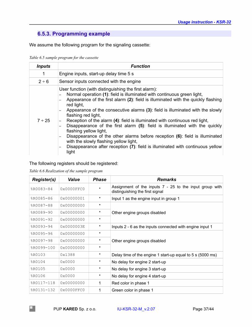
6.5.3. Programming example
We assume the following program for the signaling cassette:
Table 6.5 sample program for the cassette
Inputs Function1 Engine inputs, start-up delay time 5 s
2 ÷ 6 Sensor inputs connected with the engine
7 ÷ 25
User function (with distinguishing the first alarm):– Normal operation (1): field is illuminated with continuous green light,– Appearance of the first alarm (2): field is illuminated with the quickly flashing
red light,– Appearance of the consecutive alarms (3): field is illuminated with the slowly
flashing red light,– Reception of the alarm (4): field is illuminated with continuous red light,– Disappearance of the first alarm (5): field is illuminated with the quickly
flashing yellow light,– Disappearance of the other alarms before reception (6): field is illuminated
with the slowly flashing yellow light,– Disappearance after reception (7): field is illuminated with continuous yellow
light
The following registers should be registered:Table 6.6 Realization of the sample program
Register(s) Value Phase Remarks
%R0083-84 0x0000FFC0 * Assignment of the inputs 7 - 25 to the input group with distinguishing the first signal
%R0085-86 0x00000001 * Input 1 as the engine input in group 1%R0087-88 0x00000000 *
Other engine groups disabled%R0089-90 0x00000000 *%R0091-92 0x00000000 *%R0093-94 0x0000003E * Inputs 2 - 6 as the inputs connected with engine input 1%R0095-96 0x00000000 *
Other engine groups disabled%R0097-98 0x00000000 *%R0099-100 0x00000000 *%R0103 0x1388 * Delay time of the engine 1 start-up equal to 5 s (5000 ms)%R0104 0x0000 * No delay for engine 2 start-up%R0105 0x0000 * No delay for engine 3 start-up%R0106 0x0000 * No delay for engine 4 start-up%R0117-118 0x00000000 1 Red color in phase 1%R0131-132 0x0000FFC0 1 Green color in phase 1
PUP KARED Sp. z o.o. IU-KSR-32-M_v.2.07 Page 37/44

Usage instruction - KSR-32
Register(s) Value Phase Remarks%R0159-160 0x00000000 1 Flashing light in phase 1%R0173-174 0x0000FFC0 1 Continuous light in phase 1%R0187-188 0x00000000 1 Rate of change for the flashing light in phase 1%R0119-120 0x0000FFC0 2 Red color in phase 2%R0133-134 0x00000000 2 Green color in phase 2%R0161-162 0x0000FFC0 2 Flashing light in phase 2%R0175-176 0x00000000 2 Continuous light in phase 2%R0189-190 0x0000FFC0 2 Rate of change for the flashing light in phase 2%R0121-122 0x0000FFC0 3 Red color in phase 3%R0135-136 0x00000000 3 Green color in phase 3%R0163-164 0x0000FFC0 3 Flashing light in phase 3%R0177-178 0x00000000 3 Continuous light in phase 3%R0191-192 0x00000000 3 Rate of change for the flashing light in phase 3%R0123-124 0x0000FFC0 4 Red color in phase 4%R0137-138 0x00000000 4 Green color in phase 4%R0165-166 0x00000000 4 Flashing light in phase 4%R0179-180 0x0000FFC0 4 Continuous light in phase 4%R0193-194 0x00000000 4 Rate of change for the flashing light in phase 4%R0125-126 0x0000FFC0 5 Red color in phase 5%R0139-140 0x0000FFC0 5 Green color in phase 5%R0167-168 0x0000FFC0 5 Flashing light in phase 5%R0181-182 0x00000000 5 Continuous light in phase 5%R0195-196 0x0000FFC0 5 Rate of change for the flashing light in phase 5%R0127-128 0x0000FFC0 6 Red color in phase 6%R0141-142 0x0000FFC0 6 Green color in phase 6%R0169-170 0x0000FFC0 6 Flashing light in phase 6%R0183-184 0x00000000 6 Continuous light in phase 6%R0197-198 0x00000000 6 Rate of change for the flashing light in phase 6%R0129-130 0x0000FFC0 7 Red color in phase 7%R0143-144 0x0000FFC0 7 Green color in phase 7%R0171-172 0x00000000 7 Flashing light in phase 7%R0185-186 0x0000FFC0 7 Continuous light in phase 7%R0199-200 0x00000000 7 Rate of change for the flashing light in phase 7• N/A
PUP KARED Sp. z o.o. IU-KSR-32-M_v.2.07 Page 38/44

Usage instruction - KSR-32
6.5.4. Setting the time for the internal timer – service mode
Settings for RTC timer are possible in the service mode using the specially defined function represented below.
Address Function Year Month Day Time Minute Second CRC-LSB CRC-MSB
0x01 0x6A X X X X X X X XDate and time is represented in BCD format. In case of year, 2 last digits should be set, e.g. for 2008 setting is 08. sample date 2008-10-25 and time 14:15:00 should be entered in the form:
Address Function Year Month Day Time Minute Second CRC-LSB CRC-MSB
0x01 0x6A 0x08 0x10 0x25 0x14 0x15 0x00 X X
RTC timer is supported by the capacitor with very high capacity. To avoid any corrupted data, do not disconnect the power supply from the device for the period longer than 6 weeks. All timer errors are signalized in the register %R0249 (see registers description in Table 6.4.)
6.5.5. Setting the time for the internal timer – broadcast
Starting from software version 2.06, it is possible to broadcast the RTC time. Broadcasts are made at addres 0x00.
Address Function Year Month Day Time Minute MilisecondMSB
MilisecondLSB CRC-LSB CRC-MSB
0x01 0x66 X X X X X X X X XThe two bytes described as "Milliseconds" contain information about the current second. For example, if you want to send information about the time of 2s, 555ms, you should enter the value of 2555 in the mentioned two bytes: 0x09 (MSB) and 0xFB (LSB) respectively.According to the modbus protocol, the device does not respond to broadcast frames.
6.5.6. Writing and reading of the inputs channel names
Writing and reading of the input channels names is possible in the device software in version 2.03 and later. Writing the the name is possible only in the service mode, read-out - in any operation mode.The name can be entered using specially defined command presented below:
Address Function Channel No. Z0 Z1 ... Z62 Z63 CRC-LSB CRC-MSB
0x01 0x69 0÷31 X X ... X X X X
Command frame contains address of the target device (always 0x01 in the service mode), function number 0x69, channel number, 64 characters (Z0, Z1, ... , Z62, Z63) corresponding to the channel description and control sum CRC. The channels are numbered from "0", therefore first channel (first input) corresponds to "0", second channel to "1", etc. Complete fame contains 69 bytes, and it should such length always, even when the description contains less than 64 characters. In such case, the description should be completed with null characters (NULL - 0x00) or for example with blank characters (0x20) to provide the proper length of the frame.The response of the device after sending the proper frame includes 4 bytes as represented below:
Address Function CRC-LSB CRC-MSB
PUP KARED Sp. z o.o. IU-KSR-32-M_v.2.07 Page 39/44

Usage instruction - KSR-32
0x01 0x69 X X
Response of the device in case of registering attempt using the channel outside of the range 0÷31 is represented in the following way:
Address Function with error
Error code CRC-LSB CRC-MSB
0x01 0xE9 0x02 X X
Response of the device, when the command was send in the normal operation mode:
Address Function with error CRC-LSB CRC-MSB
X 0xE9 X X
Read-out of the channel name is possible in both operation modes and is performed by the special command:
Address Function Channel number CRC-LSB CRC-MSB
X 0x68 0÷31 X X
The frame contains device address, function number (0x68), channel number and control sum CRC. The channels are numbered from "0", therefore first channel (first input) corresponds to "0", second channel to "1", etc.
Response of the device for the properly entered query:Address Function Channel
No. Z0 Z1 ... Z62 Z63 CRC-LSB CRC-MSB
X 0x68 0÷31 X X ... X X X X
Response frame includes device address, function number, channel number, which name id read-out, 64 characters (Z0, Z1, ... , Z62, Z63) assigned to the given channel and control sum CRC.Response of the device in case of read-out attempt using the channel outside of the range 0÷31 is represented in the following way:
Address Function with error
Error code CRC-LSB CRC-MSB
X 0xE8 0x02 X X
6.5.7. Forcing service mode activation
Software forcing (via RS transmission) service mode activation is possible in the device software version 2.06 and later. Receiving the frame below by the device working in normal mode results in forcing the service mode.
PUP KARED Sp. z o.o. IU-KSR-32-M_v.2.07 Page 40/44

Usage instruction - KSR-32
Address Function Command CRC-LSB CRC-MSB
X 0x65 0x01 X X
In response to the correct frame, the device returns the same sequence of bytes.
Sending the above frame to the device working in the service mode will couse the restart of the device, load new settings (if sent) and start normal operation mode.
6.5.8. Address request
The Address request is supported in the device software version 2.06 and later. The request is sent as a broadcast:
Address Function CRC-LSB CRC-MSB
0x00 0x67 X X
In response the device returns a frame with its own address:
Address Function CRC-LSB CRC-MSB
X 0x67 X X
The function should be used with care considering that there is no collision detection and avoidance mechanism in the Modbus based on RS485 network. The address request should be used for service purposes.
7. Usage
Usage of Modbus RTU protocol is limited only to 2 functions: - „Read Holding Registers” (0x03) and „Write Multiple Registers” (0x10). There are available additionally defined functions for writing the RTC timer (see description in chapter 6.5.4), functions for writing and reading the channels names (available from firmware version 2.03, described in chapter 6.5.5) and also function used for read-out of the registered events.The query send to the signaling cassette from the master device to receive the registered event is represented below:
Address Function MSB event LSB event CRC-LSB CRC-MSB
X 0x6C X X X X
2 event bytes define, which event must be send. Entering 0 will cause that most actual event will be send, entering 999 will cause that the oldest event, last in the buffer,will be send.The device responding on the query sends the frame in the following form:Byte number Description
0 Slave device address1 Function (0x6C)
PUP KARED Sp. z o.o. IU-KSR-32-M_v.2.07 Page 41/44

Usage instruction - KSR-32
Byte number Description2 Year (last two digits in the binary code)3 Month (in the binary code)4 Day (in the binary code)5 Hour (in the binary code)6 Minute (in the binary code)7 Second (in the binary code)8 Millisecond (in the binary code - oldest byte)9 Millisecond (in the binary code - youngest byte)
10 Mask of alarm appearance (oldest byte)11 Mask of alarm appearance12 Mask of alarm appearance13 Mask of alarm appearance (youngest byte)14 Mask of alarm signal disappearance (oldest byte)15 Mask of alarm signal disappearance16 Mask of alarm signal disappearance17 Mask of alarm signal disappearance (youngest byte)18 Additional informations19 Reserved20 Record CRC (day and time of event) – LSB21 Record CRC (day and time of event) – MSB22 Transmission frame RCR– LSB23 Transmission frame RCR– MSB
Masks of alarm signal appearance or disappearance are connected with the binary inputs according to the Table 7.1.
PUP KARED Sp. z o.o. IU-KSR-32-M_v.2.07 Page 42/44

Usage instruction - KSR-32
Logical "1" registered in the given byte means appearance of the alarm signal (mask of alarm appearance) or disappearance (mask of alarm signal disappearance).
Field for additional informations (byte No. 18 in the frame) is presented in Table 7.2.
This field contains information about pressing KAA or KAO buttons, turning-on (ON) and turning-off (OFF) the device, enabling service mode (SERVICE) and eventual timer errors (RTC).
In case, when the cassette is operating in signalization forcing mode, writing data to register %R0251 will cause triggering of the corresponding channel of the device.
8. Storage
Transport packaging should have same degree of resistance to vibrations and shocks, as defined in PN-EN 60255-21-1:1999 and PN-EN 60255-21-2:2000 norms for class 1 severity.The device delivered by the manufacturer should be carefully unpacked without using excessive force and improper tools. After unpacking, the visual inspection should be performed to check any possible external damages.The device should be stored in dry and clean place, with temperature from −25 °C to +70 °C.Relative humidity should be in the range that will not cause condensation or frosting phenomenon.Before applying power supply, the device should be installed in the operation place ca. one hour earlier, to compensate temperatures and avoid humidity and condensation impacts.During very long storage periods it is recommended to power the device with auxiliary voltage for two days in every year, to regenerate electrolytic condensers.
9. Utilization
If, as a result of damage or decommissioning, disassembly of the device is needed (and eventually
PUP KARED Sp. z o.o. IU-KSR-32-M_v.2.07 Page 43/44
Table 7.1 Events mask
Byte Bits and corresponding inputs
MSBBits 7 6 5 4 3 2 1 0Inputs 32 31 30 29 28 27 26 25Bits 7 6 5 4 3 2 1 0Inputs 24 23 22 21 20 19 18 17Bits 7 6 5 4 3 2 1 0Inputs 16 15 14 13 12 11 10 9
LSBBits 7 6 5 4 3 2 1 0Inputs 8 7 6 5 4 3 2 1
Table 7.2 Additional informations
Bits 7 6 5 4 3 2 1 0Events RTC X SERVICE OFF ON KAA KAO X

Usage instruction - KSR-32
utilized), all power supplies and other active connections should be disconnected.Disassembled device should be treated as the electronic scrap material, that should be handled according to the regulations regarding scrap materials management.10. Warranty and service
KARED warrants the delivered device for the period of 12 months from the date of sale (unless the agreement stipulates otherwise).In case, when the device will be started by the KARED personnel, the warranty period can be prolonged.Manufacturer offers the technical support during start-up of the device and other warranty and after-warranty services, as defined in the corresponding agreement fir such service.In case, when the instructions provided in this document will not be observed, the warranty will be void.
11. Ordering method
The purchase order should contain informations regarding whether the device should be equipped with own binary inputs and information about value of the rating voltage.
Input rating voltage Code denomination24 V DC KSR-32-M-XXX-02448 V DC KSR-32-M-XXX-048110 V DC KSR-32-M-XXX-110220 V DC KSR-32-M-XXX-220No binary inputs KSR-32-M-XXX-000Others To be approved by the manufacturer
Power supply voltage Code denomination24 V DC KSR-32-M-024-XXX110 V DC KSR-32-M-110-XXX220 V DC / 230 V AC KSR-32-M-220-XXX
All orders should submitted directly to the manufacturer to the following address:PUP KARED Sp. z o.o.ul. Kwiatowa 3/1 Kowalepost office: 80-180 GdańskTel. (+48-58) 32 282 31fax (+48-58) 32 282 33e-mail: [email protected]: http://www.kared.com.pl/
PUP KARED Sp. z o.o. IU-KSR-32-M_v.2.07 Page 44/44

![Dimensions: [mm] Recommended Hole Pattern: [mm] Absolute ... · This electronic component has been designed and developed for usage in general electronic equipment only. This product](https://img.pdfslide.us/doc/110x75/5fbaf3fedb0bee3d492aff7e/dimensions-mm-recommended-hole-pattern-mm-absolute-this-electronic-component.jpg)